Embed Size (px)
Citation preview

�SAFETY WARNING
Only qualified personnel should install and service the equipment.The installation, starting up, and servicingof heating, ventilating, and air-conditioning equipment can be hazardous and requires specific knowledge andtraining. Improperly installed, adjusted or altered equipment by an unqualified person could result in death orserious injury. When working on the equipment, observe all precautions in the literature and on the tags,stickers, and labels that are attached to the equipment.
November 2012 BAS-SVU09H-EN
User Guide
Tracer ES™
Version 4.5
2 BAS-SVU09H-EN
Copyright
© 2012Trane All rights reserved
This document and the information in it are the property ofTrane and may not be usedor reproduced in whole or in part, without the written permission ofTrane.Trane reservesthe right to revise this publication at any time and to make changes to its content withoutobligation to notify any person of such revision or change.
Trademarks
Trane and its logo are trademarks ofTrane in the United States and other countries. Alltrademarks referenced in this document are the trademarks of their respective owners.
Warnings, Cautions, and Notices
Warnings, cautions, and notices are provided in appropriate places throughout thisdocument:
�WARNING: Indicates a potentially hazardous situation which, if not avoided,could result in death or serious injury.
�CAUTION: Indicates a potentially hazardous situation which, if not avoided,could result in minor or moderate injury. It could also be used to alert againstunsafe practices.
NOTICE: Indicates a situation that could result in equipment or property-damage-only accidents.

Table of Contents
BAS-SVU09H-EN 3
Getting Started . . . . . . . . . . . . . . . . . . . . . . . . . . . . . . . . . . . . . . . . . . . . . . . . . . . . . . . . . 8
What is Tracer ES System? . . . . . . . . . . . . . . . . . . . . . . . . . . . . . . . . . . . . . . . . . . 8
Log in to Tracer ES . . . . . . . . . . . . . . . . . . . . . . . . . . . . . . . . . . . . . . . . . . . . . . . . . 8
What’s on Every Page . . . . . . . . . . . . . . . . . . . . . . . . . . . . . . . . . . . . . . . . . . . . . . 9
Tracer ES Help and Documentation . . . . . . . . . . . . . . . . . . . . . . . . . . . . . . . . . . 9
Printing Help Information . . . . . . . . . . . . . . . . . . . . . . . . . . . . . . . . . . . . . . . . . . 10
Process Tracker: View, Clear Entries, Cancel Processes . . . . . . . . . . . . . . . . 10
Selecting, Sorting, and Filtering Tables . . . . . . . . . . . . . . . . . . . . . . . . . . . . . . 10
System Status: View . . . . . . . . . . . . . . . . . . . . . . . . . . . . . . . . . . . . . . . . . . . . . . 11
System Tasks: View . . . . . . . . . . . . . . . . . . . . . . . . . . . . . . . . . . . . . . . . . . . . . . . 12
Search Tips . . . . . . . . . . . . . . . . . . . . . . . . . . . . . . . . . . . . . . . . . . . . . . . . . . . . . . 13
Status . . . . . . . . . . . . . . . . . . . . . . . . . . . . . . . . . . . . . . . . . . . . . . . . . . . . . . . . . . . . . . . . 13
Area or Space Setpoints: Edit Globally . . . . . . . . . . . . . . . . . . . . . . . . . . . . . . . 13
Missing Status Data . . . . . . . . . . . . . . . . . . . . . . . . . . . . . . . . . . . . . . . . . . . . . . . 14
Equipment and Subsystems: Add or Remove Data . . . . . . . . . . . . . . . . . . . . 14
Air Handlers: View . . . . . . . . . . . . . . . . . . . . . . . . . . . . . . . . . . . . . . . . . . . . . . . . 15
Areas: View . . . . . . . . . . . . . . . . . . . . . . . . . . . . . . . . . . . . . . . . . . . . . . . . . . . . . . 16
Analog Inputs and Binary Inputs: View . . . . . . . . . . . . . . . . . . . . . . . . . . . . . . . 16
Analog Outputs, Binary Outputs, and Setpoints: View . . . . . . . . . . . . . . . . . 16
Analog Inputs and Binary Inputs: View . . . . . . . . . . . . . . . . . . . . . . . . . . . . . . . 16
Analog Outputs, Binary Outputs, and Setpoints: View . . . . . . . . . . . . . . . . . 16
Heat Pump Loops: View . . . . . . . . . . . . . . . . . . . . . . . . . . . . . . . . . . . . . . . . . . . 17
Chiller Plants: View and Control . . . . . . . . . . . . . . . . . . . . . . . . . . . . . . . . . . . . . 17
Chillers: View . . . . . . . . . . . . . . . . . . . . . . . . . . . . . . . . . . . . . . . . . . . . . . . . . . . . . 18
Spaces: View . . . . . . . . . . . . . . . . . . . . . . . . . . . . . . . . . . . . . . . . . . . . . . . . . . . . . 18
Variable Air Subsystems: View . . . . . . . . . . . . . . . . . . . . . . . . . . . . . . . . . . . . . 18
VariTrac Systems: View . . . . . . . . . . . . . . . . . . . . . . . . . . . . . . . . . . . . . . . . . . . . 18
Programmable Controllers: View and Customize . . . . . . . . . . . . . . . . . . . . . . 19
Buildings . . . . . . . . . . . . . . . . . . . . . . . . . . . . . . . . . . . . . . . . . . . . . . . . . . . . . . . . . . . . . 19
Building Summary: View . . . . . . . . . . . . . . . . . . . . . . . . . . . . . . . . . . . . . . . . . . . 19
Buildings: Add . . . . . . . . . . . . . . . . . . . . . . . . . . . . . . . . . . . . . . . . . . . . . . . . . . . . 20
Buildings: View or Delete Discovery Report . . . . . . . . . . . . . . . . . . . . . . . . . . 21
Building Attributes: View, Edit, Create Custom . . . . . . . . . . . . . . . . . . . . . . . . 22Overview . . . . . . . . . . . . . . . . . . . . . . . . . . . . . . . . . . . . . . . . . . . . . . . . . . . 22View or Edit . . . . . . . . . . . . . . . . . . . . . . . . . . . . . . . . . . . . . . . . . . . . . . . . . 23Create Custom . . . . . . . . . . . . . . . . . . . . . . . . . . . . . . . . . . . . . . . . . . . . . . . 23
Building Navigation Sidebar . . . . . . . . . . . . . . . . . . . . . . . . . . . . . . . . . . . . . . . . 24

4 BAS-SVU09H-EN
Buildings: Run Reports . . . . . . . . . . . . . . . . . . . . . . . . . . . . . . . . . . . . . . . . . . . . 25
Buildings: Synchronize Manually . . . . . . . . . . . . . . . . . . . . . . . . . . . . . . . . . . . . 25
Buildings: Customize Grouping . . . . . . . . . . . . . . . . . . . . . . . . . . . . . . . . . . . . . 26
Panel: Reset, Clear RAM, Delete . . . . . . . . . . . . . . . . . . . . . . . . . . . . . . . . . . . . . 26Reset or Clear RAM . . . . . . . . . . . . . . . . . . . . . . . . . . . . . . . . . . . . . . . . . . . 26Delete . . . . . . . . . . . . . . . . . . . . . . . . . . . . . . . . . . . . . . . . . . . . . . . . . . . . . . 27
BACnet Objects and Properties: View, Edit . . . . . . . . . . . . . . . . . . . . . . . . . . . 27
Panel Communication Alarms: View, Create, Edit, Delete . . . . . . . . . . . . . . . 28
Tracer SC Panels: View Directly . . . . . . . . . . . . . . . . . . . . . . . . . . . . . . . . . . . . . 29
BCU Phone Book: View, Edit . . . . . . . . . . . . . . . . . . . . . . . . . . . . . . . . . . . . . . . . 29
Navigation Tree: Use, Edit, Backup, Restore . . . . . . . . . . . . . . . . . . . . . . . . . . 30
Custom Pages: Assign to Building . . . . . . . . . . . . . . . . . . . . . . . . . . . . . . . . . . . 31
Alarms . . . . . . . . . . . . . . . . . . . . . . . . . . . . . . . . . . . . . . . . . . . . . . . . . . . . . . . . . . . . . . . 32
Alarms: View, Acknowledge, Remove . . . . . . . . . . . . . . . . . . . . . . . . . . . . . . . 32
Alarms: Advanced Search (and Remove) . . . . . . . . . . . . . . . . . . . . . . . . . . . . . 34
Alarm Comments: View or add . . . . . . . . . . . . . . . . . . . . . . . . . . . . . . . . . . . . . 34
Alarms: Ignoring . . . . . . . . . . . . . . . . . . . . . . . . . . . . . . . . . . . . . . . . . . . . . . . . . . 35
Ignored Alarm Rules: View or Delete . . . . . . . . . . . . . . . . . . . . . . . . . . . . . . . . 35
Alarm Priority Levels and Alarm Notification Classes: Edit . . . . . . . . . . . . . . 36
Alarm Priorities: Mapping . . . . . . . . . . . . . . . . . . . . . . . . . . . . . . . . . . . . . . . . . . 38
Alarm E-mail and SMS Text Message Templates: View, Create, Delete, Assign39
Alarm Panel Subscriptions: Managing . . . . . . . . . . . . . . . . . . . . . . . . . . . . . . . 40
E-mail and SMS Text Message Routing: Setup Server . . . . . . . . . . . . . . . . . 41
Alarm E-mail and SMS Text Message Templates: View, Create, Delete, Assign42
E-mail Addresses for Alarm Routing: Add, View, Edit, Delete . . . . . . . . . . . 43
Alarm E-mail Routing Rule: Create, Edit, View, Delete . . . . . . . . . . . . . . . . . . 44
Audible Alarms: Setup . . . . . . . . . . . . . . . . . . . . . . . . . . . . . . . . . . . . . . . . . . . . . 45
Schedules . . . . . . . . . . . . . . . . . . . . . . . . . . . . . . . . . . . . . . . . . . . . . . . . . . . . . . . . . . . . 46
Scheduling Overview . . . . . . . . . . . . . . . . . . . . . . . . . . . . . . . . . . . . . . . . . . . . . . 46
Normal Schedule: Create, View, Edit . . . . . . . . . . . . . . . . . . . . . . . . . . . . . . . . 46
Exception Schedule: Create, View, Edit, Cancel . . . . . . . . . . . . . . . . . . . . . . . 47
Schedule Attributes: Create, View, Rename, Delete, Publish, Assign . . . . . 48
Emergency Schedule: Create, View, Edit, Activate, Deactivate . . . . . . . . . . 50
Exception Template: Create, View, Edit, Delete, Apply . . . . . . . . . . . . . . . . . 51
Schedule Events Color Coding . . . . . . . . . . . . . . . . . . . . . . . . . . . . . . . . . . . . . . 53

BAS-SVU09H-EN 5
Panel Schedules: View . . . . . . . . . . . . . . . . . . . . . . . . . . . . . . . . . . . . . . . . . . . . . 53
Global Schedule Changes . . . . . . . . . . . . . . . . . . . . . . . . . . . . . . . . . . . . . . . . . . 54
Reports . . . . . . . . . . . . . . . . . . . . . . . . . . . . . . . . . . . . . . . . . . . . . . . . . . . . . . . . . . . . . . . 55
Completed Reports: View, E-mail, or Delete . . . . . . . . . . . . . . . . . . . . . . . . . . 55
Reports: Create, Modify, and Import Custom Reports . . . . . . . . . . . . . . . . . . 55
Reports: Scheduling, Exporting, and E-mail Notifications . . . . . . . . . . . . . . . 60
Users . . . . . . . . . . . . . . . . . . . . . . . . . . . . . . . . . . . . . . . . . . . . . . . . . . . . . . . . . . . . . . . . . 61
Password: Changing Your Own . . . . . . . . . . . . . . . . . . . . . . . . . . . . . . . . . . . . . 61
User Preferences: View, Edit . . . . . . . . . . . . . . . . . . . . . . . . . . . . . . . . . . . . . . . . 61
User Profiles: Create, View, Edit, Delete, Activate, Deactivate . . . . . . . . . . . 62
User Roles: Assign . . . . . . . . . . . . . . . . . . . . . . . . . . . . . . . . . . . . . . . . . . . . . . . . 63
User Roles: Create, View, Edit, Delete . . . . . . . . . . . . . . . . . . . . . . . . . . . . . . . . 64
Password and User ID Security Policy: View, Edit . . . . . . . . . . . . . . . . . . . . . 65
User Change Log: View or Delete Entries . . . . . . . . . . . . . . . . . . . . . . . . . . . . . 66
Overrides . . . . . . . . . . . . . . . . . . . . . . . . . . . . . . . . . . . . . . . . . . . . . . . . . . . . . . . . . . . . . 67
Simplified Overrides: Create . . . . . . . . . . . . . . . . . . . . . . . . . . . . . . . . . . . . . . . 67
Advance Overrides: View, Create, Release . . . . . . . . . . . . . . . . . . . . . . . . . . . . 68
VAV II/II/IV: Advanced Overrides . . . . . . . . . . . . . . . . . . . . . . . . . . . . . . . . . . . . 69Calibrate Valve . . . . . . . . . . . . . . . . . . . . . . . . . . . . . . . . . . . . . . . . . . . . . . . 70Drive Open . . . . . . . . . . . . . . . . . . . . . . . . . . . . . . . . . . . . . . . . . . . . . . . . . . 70Drive Closed . . . . . . . . . . . . . . . . . . . . . . . . . . . . . . . . . . . . . . . . . . . . . . . . . 70Drive Min . . . . . . . . . . . . . . . . . . . . . . . . . . . . . . . . . . . . . . . . . . . . . . . . . . . 71Drive Max . . . . . . . . . . . . . . . . . . . . . . . . . . . . . . . . . . . . . . . . . . . . . . . . . . . 71Parallel Fan Control . . . . . . . . . . . . . . . . . . . . . . . . . . . . . . . . . . . . . . . . . . . 71Terminal Heat . . . . . . . . . . . . . . . . . . . . . . . . . . . . . . . . . . . . . . . . . . . . . . . 71Drive Open Hot Water Outputs/Valve . . . . . . . . . . . . . . . . . . . . . . . . . . . . 71Control Offset . . . . . . . . . . . . . . . . . . . . . . . . . . . . . . . . . . . . . . . . . . . . . . . . 72Control Offset Value . . . . . . . . . . . . . . . . . . . . . . . . . . . . . . . . . . . . . . . . . . 72Minimum Flow Setpoint Multiplier . . . . . . . . . . . . . . . . . . . . . . . . . . . . . . 72Multiplier Value . . . . . . . . . . . . . . . . . . . . . . . . . . . . . . . . . . . . . . . . . . . . . . 72
Space Comfort Controller (v14 & earlier): Advanced Overrides . . . . . . . . . . 73Water Valve . . . . . . . . . . . . . . . . . . . . . . . . . . . . . . . . . . . . . . . . . . . . . . . . . 73Air Valve . . . . . . . . . . . . . . . . . . . . . . . . . . . . . . . . . . . . . . . . . . . . . . . . . . . . 73
Space Comfort Controller (v15 & later): Advanced Overrides . . . . . . . . . . . 74Water Valve . . . . . . . . . . . . . . . . . . . . . . . . . . . . . . . . . . . . . . . . . . . . . . . . . 74Air Valve . . . . . . . . . . . . . . . . . . . . . . . . . . . . . . . . . . . . . . . . . . . . . . . . . . . . 74Auto Commissioning Sequence Group . . . . . . . . . . . . . . . . . . . . . . . . . . . 75
Voyager Rooftop Unit: Advanced Overrides . . . . . . . . . . . . . . . . . . . . . . . . . . 75Compressor Control . . . . . . . . . . . . . . . . . . . . . . . . . . . . . . . . . . . . . . . . . . 75Cooling Stages Enabled . . . . . . . . . . . . . . . . . . . . . . . . . . . . . . . . . . . . . . . 76Pressurization Mode . . . . . . . . . . . . . . . . . . . . . . . . . . . . . . . . . . . . . . . . . . 76

6 BAS-SVU09H-EN
Exhaust Mode . . . . . . . . . . . . . . . . . . . . . . . . . . . . . . . . . . . . . . . . . . . . . . . 76Purge Mode . . . . . . . . . . . . . . . . . . . . . . . . . . . . . . . . . . . . . . . . . . . . . . . . . 77Outside Air Dampers . . . . . . . . . . . . . . . . . . . . . . . . . . . . . . . . . . . . . . . . . . 77Heating Control . . . . . . . . . . . . . . . . . . . . . . . . . . . . . . . . . . . . . . . . . . . . . . 77Enable Emergency Heat Mode . . . . . . . . . . . . . . . . . . . . . . . . . . . . . . . . . . 77Disable Auxiliary Heat . . . . . . . . . . . . . . . . . . . . . . . . . . . . . . . . . . . . . . . . . 77Service Test Group . . . . . . . . . . . . . . . . . . . . . . . . . . . . . . . . . . . . . . . . . . . 77
Commercial Self-Contained Unit: Advanced Overrides . . . . . . . . . . . . . . . . . 78Mechanical Cooling Control . . . . . . . . . . . . . . . . . . . . . . . . . . . . . . . . . . . . 78Heating Control . . . . . . . . . . . . . . . . . . . . . . . . . . . . . . . . . . . . . . . . . . . . . . 78Ventilation Control . . . . . . . . . . . . . . . . . . . . . . . . . . . . . . . . . . . . . . . . . . . 78Maximum Ventilation Control . . . . . . . . . . . . . . . . . . . . . . . . . . . . . . . . . . 78
Intellipack Rooftop Unit: Advanced Overrides . . . . . . . . . . . . . . . . . . . . . . . . . 79Heating Control . . . . . . . . . . . . . . . . . . . . . . . . . . . . . . . . . . . . . . . . . . . . . . 79Cooling Control . . . . . . . . . . . . . . . . . . . . . . . . . . . . . . . . . . . . . . . . . . . . . . 79Ventilation Overrides . . . . . . . . . . . . . . . . . . . . . . . . . . . . . . . . . . . . . . . . . 79
Terminal Unit Controller: Advanced Overrides . . . . . . . . . . . . . . . . . . . . . . . . 79Valve 1 - Closed . . . . . . . . . . . . . . . . . . . . . . . . . . . . . . . . . . . . . . . . . . . . . . 80Valve 1 - Open . . . . . . . . . . . . . . . . . . . . . . . . . . . . . . . . . . . . . . . . . . . . . . . 80Valve 1 - Face and Bypass Closed . . . . . . . . . . . . . . . . . . . . . . . . . . . . . . . 81Valve 1 - Face and Bypass Open . . . . . . . . . . . . . . . . . . . . . . . . . . . . . . . . 81Valve 2 - Closed . . . . . . . . . . . . . . . . . . . . . . . . . . . . . . . . . . . . . . . . . . . . . . 82Valve 2 - Open . . . . . . . . . . . . . . . . . . . . . . . . . . . . . . . . . . . . . . . . . . . . . . . 82Valve 2 - Face and Bypass Closed . . . . . . . . . . . . . . . . . . . . . . . . . . . . . . . 82Valve 2 - Face and Bypass Open . . . . . . . . . . . . . . . . . . . . . . . . . . . . . . . . 83Outdoor Air Damper - Closed . . . . . . . . . . . . . . . . . . . . . . . . . . . . . . . . . . . 83Outdoor Air Damper - Open . . . . . . . . . . . . . . . . . . . . . . . . . . . . . . . . . . . . 84Exhaust Fan - Off . . . . . . . . . . . . . . . . . . . . . . . . . . . . . . . . . . . . . . . . . . . . . 84Exhaust Fan - On . . . . . . . . . . . . . . . . . . . . . . . . . . . . . . . . . . . . . . . . . . . . . 84
Overrides: View All . . . . . . . . . . . . . . . . . . . . . . . . . . . . . . . . . . . . . . . . . . . . . . . . 85
Global Overrides: Create . . . . . . . . . . . . . . . . . . . . . . . . . . . . . . . . . . . . . . . . . . . 86
Global Point Control . . . . . . . . . . . . . . . . . . . . . . . . . . . . . . . . . . . . . . . . . . . . . . . . . . . 87
Virtual Point (Trigger): Create, Edit, Delete . . . . . . . . . . . . . . . . . . . . . . . . . . . 87
Global References: Create, Edit, Delete, View Log . . . . . . . . . . . . . . . . . . . . 88
Graphics . . . . . . . . . . . . . . . . . . . . . . . . . . . . . . . . . . . . . . . . . . . . . . . . . . . . . . . . . . . . . . 89
Graphics: List, Discover . . . . . . . . . . . . . . . . . . . . . . . . . . . . . . . . . . . . . . . . . . . . 89
Graphics: Assign to Buildings and Objects . . . . . . . . . . . . . . . . . . . . . . . . . . . 90
Custom Pages: Assign to Building . . . . . . . . . . . . . . . . . . . . . . . . . . . . . . . . . . . 91
Data Logs . . . . . . . . . . . . . . . . . . . . . . . . . . . . . . . . . . . . . . . . . . . . . . . . . . . . . . . . . . . . . 92
Data Logs: Create, Edit, and Delete . . . . . . . . . . . . . . . . . . . . . . . . . . . . . . . . . . 92
Data Log Graphs and Tables: View, Edit . . . . . . . . . . . . . . . . . . . . . . . . . . . . . . 93
Data Logs: Description and Reference Information . . . . . . . . . . . . . . . . . . . . 93

BAS-SVU09H-EN 7
Types of Data Logs . . . . . . . . . . . . . . . . . . . . . . . . . . . . . . . . . . . . . . . . . . . 94Time Zones . . . . . . . . . . . . . . . . . . . . . . . . . . . . . . . . . . . . . . . . . . . . . . . . . 94Snapshot Trends . . . . . . . . . . . . . . . . . . . . . . . . . . . . . . . . . . . . . . . . . . . . . 94Failed Panel Communication . . . . . . . . . . . . . . . . . . . . . . . . . . . . . . . . . . . 94Tracer ES Server Failure . . . . . . . . . . . . . . . . . . . . . . . . . . . . . . . . . . . . . . . 94Data Log Staging . . . . . . . . . . . . . . . . . . . . . . . . . . . . . . . . . . . . . . . . . . . . . 95Collection Notification . . . . . . . . . . . . . . . . . . . . . . . . . . . . . . . . . . . . . . . . . 95
Data Log Attributes: Create, Assign . . . . . . . . . . . . . . . . . . . . . . . . . . . . . . . . . . 95
Licensing . . . . . . . . . . . . . . . . . . . . . . . . . . . . . . . . . . . . . . . . . . . . . . . . . . . . . . . . . . . . . 96
Tracer ES Licensing . . . . . . . . . . . . . . . . . . . . . . . . . . . . . . . . . . . . . . . . . . . . . . . 96
License File: Install . . . . . . . . . . . . . . . . . . . . . . . . . . . . . . . . . . . . . . . . . . . . . . . . 96
Licensing Information: View, Register, or Change . . . . . . . . . . . . . . . . . . . . . 98
License Administration: View or Change Licence Allocation . . . . . . . . . . . . 98
Customizing . . . . . . . . . . . . . . . . . . . . . . . . . . . . . . . . . . . . . . . . . . . . . . . . . . . . . . . . . . . 99
Home Page Custom Links: Define, Remove . . . . . . . . . . . . . . . . . . . . . . . . . . . 99
System Parameters: View, Edit . . . . . . . . . . . . . . . . . . . . . . . . . . . . . . . . . . . . 100
Buildings: Customize Grouping . . . . . . . . . . . . . . . . . . . . . . . . . . . . . . . . . . . . 102
Process Tracker: View, Clear Entries, Cancel Processes . . . . . . . . . . . . . . . 102
Database: Manage Size . . . . . . . . . . . . . . . . . . . . . . . . . . . . . . . . . . . . . . . . . . . 103Overview . . . . . . . . . . . . . . . . . . . . . . . . . . . . . . . . . . . . . . . . . . . . . . . . . . 103Database Size Management . . . . . . . . . . . . . . . . . . . . . . . . . . . . . . . . . . . 103Application Log management . . . . . . . . . . . . . . . . . . . . . . . . . . . . . . . . . 104Viewing and Making changes . . . . . . . . . . . . . . . . . . . . . . . . . . . . . . . . . 104

8 BAS-SVU09H-EN
Getting Started
What isTracer ES System?
TheTracer ES system is aWeb-enabled service and monitoring tool for multiple building facilities.Its adherence to IT standards enablesTracer ES to integrate building systems into a cohesiveenterprise-wide system using open standards. It is easily added to new or existingTracer Summitinstallations on BACnet/IP networks. Once installed and configured, building operators andadministrators can access theTracer ES server from the local network or internet to monitor andcontrol the building system.
Log in toTracer ES
AllTracer ES users must know the IP address (example 168.0.100.1) or the URL (example http://www.traceres.trane.com/live) of theTracer ES server and have a User ID and password, which canbe created by a system administrator.
To log in toTracer ES:1. Launch one of the following internet browsers:
• Apple Safari version 3.0 or later.
• Microsoft Internet Explorer version 7.0 or later.
• Mozilla Firefox version 3.0 or later.2. Enter the address of theTracer ES server into the browser’s address bar.Tracer ES may take
up to a minute to load, depending on available network and computer resources.3. Select an alternate language, if needed, by clicking the button for the desired language. There
are some additional regional settings you can change if you edit your preferences.4. Type your User ID and password as indicated, then click Login.
Note: If it is your first time logging in to the software, you must read and accept theTermsof Service agreement to continue. Read the agreement (you must scroll down to thebottom), then clickYes, I do accept, and Continue to indicate your agreement.
Figure 1. Login

BAS-SVU09H-EN 9
What’s on Every Page
What’s on Every Page
The content area on everyTracer ES page changes from page to page. But all pages* contain thisheader, which includes the following links:
Figure 2. Tracer ES Header
• My Home - go to the location you have designated as your home page.• Change Password - change your user password.• Logout - end yourTracer ES session and return to the login page.• Help (Text link) - launch the complete online help system.• Help (Icon ) - launch the help page written for the page you are on.
• Tracer ES Home - go to the mainTracer ES System home page.• All Alarms - go to the main alarms page to see all the alarms in the system.• Reports - go to the main report page to access completed reports or create a custom report.• Preferences - view or change your user preferences, including general information, data
display values (units of measurement), and regional settings.• Administration - view or change administrative settings for users, buildings, applications, logs,
and system maintenance. (This area requires administrative access permission.)• Find Building(s) - search for buildings by name. Click SearchTips for additional information.• ProcessTracker Icon ( ) - View the ProcessTracker.• Bread Crumbs (Home / ...) - see where you are in the hierarchy of theTracer ES menus and click
a link to go to a place higher in the organization.
Note:The bread crumbs do not always exactly match the "Go to" path in user procedures.For instance if a procedural step is written "Go to Home / building name / Schedules /Exceptions," you click Home, then the building name, then on the building navigationsidebar click Schedules, then Exceptions. However, when you arrive at your destinationpage, the bread crumbs indicate you are at "Home / (your building name) / Manage BuildingSchedules / Manage Exception Schedules." Likewise, there is often more than one way toreach the same destination page.The procedures are written to indicate the briefest routeto the desired destination.
*Note: Pages with custom graphics may appear without the top page header.This is anoption that can be specified by the graphic creator inTracer Graphics Editor.
Tracer ES Help and Documentation
Following is a list of documentation associated withTracer ES. Links in the list will open thedocuments in PDF format:• Installation Guide - to be used by system administrators to installTracer ES.• User's Guide - a printable document based on the operations tasks of the online help to be used
by building operators for daily operation and reference.• Online Help - contains all of the content of the User's Guide, plus page-level help that can be
accessed by clicking Help or on theTracer ES pages.• Release Notes - Also called a "README" file. A description of changes made since the previous
release ofTracer ES, and other information related to this release.

10 BAS-SVU09H-EN
Printing Help Information
Printing Help Information
To print an individual topic or page, use your browser's printing function or click the "Print" link atthe bottom of the page of the page you want to print.
ProcessTracker: View, Clear Entries, Cancel Processes
The ProcessTracker is a way for you to keep track of progress whenTracer ES is sendinginformation to building panels. Whenever you create or make a change that must be written to oneor more panels, the ProcessTracker creates an entry for the new process, and opens the ProcessTracker in a new window.
Note: If the ProcessTracker is already open in a window behind the active window, it willnot automatically move in front of the active window. If you do not see the ProcessTrackerwhen you expect it to open, look behind the active window.
To open the process tracker window and view your completed and in-progress processes:• Click .
Figure 3. ProcessTracker
Note: EachTracer ES user has his or her own process tracker data.You will not see processesthat were initiated by other users who were logged into a different user account.To seeactivities performed by other users, view the SystemTask log.
To remove entries from the process tracker:1. Click to open the ProcessTracker.2. Do one of the following:
• To clear a completed single process, click Clear on the same row as the process.
• To clear all completed processes in the ProcessTracker, click Clear All.
Note: Cleared processes are permanently removed from the ProcessTracker, but theprocess is not stopped.
To cancel processes:1. Click to open the ProcessTracker.2. Click Cancel on the same row as the process.
Selecting, Sorting, and FilteringTables
Tables appear throughoutTracer ES system. Here is some basic information to help you work withthe data in the tables.
Some tables contain selectable items within the cells. When an item is selectable it appears as atext link (usually blue and underlined). To select it, click on the link.

BAS-SVU09H-EN 11
System Status: View
Most tables contain selectable rows. After you select rows, you can use the buttons on the rightside of the table. Some buttons apply to a single item, but many can be performed on more thanone item.• To select or clear a single row, click its check box. A selected check box contains a check mark.• To select or clear all rows in a table, click the check box in the table header.
To sort the data that appears in a table:1. Select which column you want to determine the sort order.2. Click on the text in the column heading. (The text becomes a blue, underlined link when the
mouse pointer hovers over it.)
Figure 4. Table Header
Notice the arrow that appears next to the text.• An arrow pointing up () indicates that the table is sorted so lower numbers and letters closer
to “A” are at the top.• An arrow pointing down () indicates that the table is sorted so higher numbers and letters closer
to “Z” are at the top.
You can use the filter to reduce the number of results that appear in the table below it.
Figure 5. Table Filter
To use the filter:
Note:You can enable or disable the filter in your user preferences. If disabled, you will notsee the filter controls at the top of the table.
1. Select one of the table columns next to For Column. Only columns that appear in the table willappear in the list.
2. If Show Only is a drop-down list, select one of the items in the list; If Show Only is a text box,type in the name of the item you are looking for.
3. ClickApply Filter.Any data entries in the table that do not have the selected value in the selectedcolumn are hidden.
To turn off the filter and show all results, select No filter, view all next to For Column.
System Status: View
BecauseTracer ES is made up of several individual applications that work together, you may findit useful to be able to view the status of the applications as a way to confirm expected operationof the software or to locate a problem in the system.

12 BAS-SVU09H-EN
SystemTasks: View
To view the system status:• Go to Home / Administration / System Maintenance / System Status.
Figure 6. System Status Page
SystemTasks: View
When a user tries to write a change to a building in the system and the change does not completesuccessfully, an entry is made into the SystemTask log.The type of tasks that can appear in thesystem task log are scheduling, communication, trending, and system tasks. It may be useful tolook at the SystemTask log to identify details about why it did not complete, what application wasinvolved, etc.

BAS-SVU09H-EN 13
SearchTips
To view the system tasks:• Go to Home / Administration / System Logs / SystemTasks.
Figure 7. SystemTasks Page
SearchTips
The search engine searches the building names or other attributes for the characters you type inthe Find Buildings box. Here are some tips:• Search terms must be exactly correct, including spaces and punctuation, but without regard to
word capitalization. For example, if you are looking for all buildings with "St. Paul" in anattribute, none of the following search terms would find them: "St Paul" "StPaul" "St. Paul""Saint Paul."
• Incomplete search terms will find results. For example, searching for just "St" would findbuildings with any of the following attribute values: "stpaul" "oak st." "St. Paul."
• The search does not support Boolean or similar operators (AND, OR, NOT) or wildcards (*).• The search will return results containing the search terms for any standard or custom attribute,
even if the attribute does not appear on the search results page. For example, if a buildingcontact person's name is John Doe, searching for "Doe" will return all buildings with John Doelisted for the contact, but you will not see "John Doe" on the search results page.
• The search engine will not show you buildings if your user profile does not have access to them.
Status
Area or Space Setpoints: Edit Globally
WithTracer ES global change capability, you can quickly initiate the same edits to any number ofarea or space setpoints across your entire building network. Changes take effect as quickly as theycan be communicated to the individual building panels.

14 BAS-SVU09H-EN
To edit setpoints globally:1. Go to Home / All Buildings.2. Select the buildings for which you want to change the setpoints.3. Click Global Changes.The Global Changes page appears.4. Click Edit Setpoints.5. Complete the series of pages and click Finish when you reach the end.
Figure 8. Global Edit Setpoints Screen
Missing Status Data
In the event of a communication problem or improper configuration, some status information maybe missing from the status screen. When this occurs, “---” appears where the data would havebeen.
Figure 9. Missing Status Data
Equipment and Subsystems: Add or Remove Data
For each type of equipment or subsystem, you can choose which data points will appear on thestatus page. Data points that are not displayed on the main status page will still be visible whenusers click More Status Values.

BAS-SVU09H-EN 15
Air Handlers: View
To customize which data points are shown for an equipment type:
Note:These changes will apply to all users.1. Go to Home / Administration / Global Applications / Customize System Pages.2. Click Add/Remove Data Shown on Equipment or Subsystem Page(s).3. Select one of the options for Equipment or Subsystem FamilyType to Customize.4. Put a check mark next to each point you want to be shown for the equipment or subsystem type.5. Clear the check mark for equipment or subsystem types you do not want shown.6. Click Finish to save your changes.
Figure 10. Add or Remove Data
Air Handlers: View
Air handlers meter air to spaces at a specific temperature setpoint.They are often configured witheconomizers that allow fresh air ventilation and recirculation.Typically the amount of air is basedon the number of spaces currently occupied.
Note: Some programmable controllers are configured to run as air handlers and will not berecognized as air handlers byTracer ES.After discovery, you can customize a programmablecontroller to be an air handler. See Programmable Controllers: View and Customize.
To view the status of an air handler:1. Go to Home / Building Name / Equipment / Air Handlers. A table appears with an air handler
in each row and basic status data in each column.2. Click on the name of the air handler you want to view. The individual air handler status page
appears.

16 BAS-SVU09H-EN
Areas: View
Areas: View
An area is created and managed by the building controller. It is an association of objects, called"members," typically serving a physical region within the building, such as a room, wing, or floor.Areas are created to provide operators a simplified way to control multiple objects in a coordinatedand potentially more energy efficient way, while at the same time ensuring that area occupantsexperience the same level of comfort throughout the area.
To view the status of an area:1. Go to Home / Building Name / Subsystems /Area. A table appears with an area in each row and
basic status data in each column.2. Click on the name of the area you want to view. The individual area status page appears.
Analog Inputs and Binary Inputs: View
Analog inputs and binary inputs are software objects in the building control panel that typicallyrepresent hard-wired or wireless sensors in the building.They could also represent values that arenot read from a sensor but are manually manipulated at the building control panel. The names ofthe inputs are edited with the appropriate service tool for the building control panel (for example,Tracer Summit orTracker software).
To view the current value of an analog input or binary input:• Go to Home / Building Name / Subsystems / Input/Output / Analog Inputs or Binary Inputs. A
table appears with an input in each row and basic status data in each column.
Analog Outputs, Binary Outputs, and Setpoints: View
Binary outputs are software objects in the building control panel and may or may not directlyrepresent physical outputs on building controllers. The names of the outputs and values are editedwith the appropriate service tool for the building control panel (for example,Tracer Summit orTracerTracker software).
To view the current value of an analog output, binary output or setpoint:• Go to Home / building name / Subsystems / Input/Output / Analog Outputs and Setpoints or
Binary Outputs and Setpoints.A table appears with an output or setpoint in each row and basicstatus data in each column.
Analog Inputs and Binary Inputs: View
Analog inputs and binary inputs are software objects in the building control panel that typicallyrepresent hard-wired or wireless sensors in the building.They could also represent values that arenot read from a sensor but are manually manipulated at the building control panel. The names ofthe inputs are edited with the appropriate service tool for the building control panel (for example,Tracer Summit orTracker software).
To view the current value of an analog input or binary input:• Go to Home / Building Name / Subsystems / Input/Output / Analog Inputs or Binary Inputs. A
table appears with an input in each row and basic status data in each column.
Analog Outputs, Binary Outputs, and Setpoints: View
Binary outputs are software objects in the building control panel and may or may not directlyrepresent physical outputs on building controllers. The names of the outputs and values are editedwith the appropriate service tool for the building control panel (for example,Tracer Summit orTracerTracker software).

BAS-SVU09H-EN 17
Heat Pump Loops: View
To view the current value of an analog output, binary output or setpoint:• Go to Home / building name / Subsystems / Input/Output / Analog Outputs and Setpoints or
Binary Outputs and Setpoints.A table appears with an output or setpoint in each row and basicstatus data in each column.
Heat Pump Loops: View
Heat pump loops are HVAC applications that operate multiple heat pump controllers (which arealso spaces) running pumps that move water through the loop.
Heat pump loops have characteristics of air systems and chiller plants:• Like air systems, they determine the overall operation of the water loop based on the demands
of the space controllers.• Like chiller plants, their primary function is to provide water at the proper temperature to the
HVAC system.
Water-source heat pump systems consist of three controllers:• A water-source-heat-pump controller stages the HVAC unit fan, compressors, and heaters to
control space temperature.• ATracer Loop Controller (TLC) runs the water loop pump, boilers and/or cooling towers to
control the water temperature inside the loop.• TheTracer Summit BCU orTracker panel coordinates theTLC and the HVAC controllers.
To view a heat pump loop:1. Go to Home / Building Name / Subsystems / Heat Pump Loop. The Heat Pump Loops page
appears.2. Click on the name of the heat pump loop you want to view. The Heat Pump Loop page appears,
which is a list of the Spaces/Heat Pump Controllers in the loop.
Chiller Plants: View and Control
Chiller plants are HVAC applications that regulate the operation of multiple chillers to provide aconstant supply of chilled water at a specific temperature (setpoint). Chiller plants start and stopchillers as required by the chilled water demanded by the system and can also regulate theoperation of the pumps that move the chilled water through the building.
InTracer ES, you can use the Chiller Plant page to view, set up data logs, and control chiller plantsin the following ways:• Manually rotate the chillers in the plant (Force Rotate). Normally the chillers rotate according
to a specified interval.• Manually put a chiller into service or take a chiller out of service (ForceAdd and Force Subtract).
Normally the number of chillers in service is configured to change based on chilled waterdemand. You do not choose which chiller gets added or subtracted, because that is stilldetermined by the chiller plant settings.
• Reassign the rotational order of the swing and numbered chillers.• Make a chiller unavailable or available to the chiller plant (it must be a chiller that is already a
member of the plant).• Reset a chiller that has stopped due to a failure condition.
Note: For more information aboutTrane chiller plant operations, consult theTracer Summitprogramming and service documentation and engineering bulletins.
To view and control a chiller plant:1. Go to Home / Building Name / Subsystems / Chiller Plant. The Chiller Plants page appears.2. Click on the name of the chiller plant you want to view. The individual chiller plant status page
appears, which is a list of the chillers in the plant.3. Use the action buttons on the page to make changes to the chiller plant operation.

18 BAS-SVU09H-EN
Chillers: View
Chillers: View
A chiller is a piece of equipment that provides a flow of chilled water usually to air handlers or spacecontrollers to cool or dehumidify room air.There are many types and sizes of chiller, which affectsthe number and type of data points that appear for them inTracer ES.
To view the status of an a chiller:1. Go to Home / Building Name / Equipment / Chiller. A table appears with a chiller in each row
and basic status data in each column.2. Click on the name of the chiller you want to view. The individual chiller status page appears.
Spaces: View
A space is a controller with primary responsibility for the comfort conditions of a single region orroom in a building. A space can be small and simple (an individual damper controller) or large andcomplex (a rooftop unit with multiple compressors).
To view the status of a space:1. Go to Home / Building Name / Spaces.A table appears with a space in each row and basic status
data in each column.2. Click on the name of the space you want to view. The individual space status page appears.
Variable Air Subsystems: View
A variable air subsystem coordinates air handlers and spaces to efficiently provide conditioned airto the HVAC system.
To view the status of a variable air subsystem:1. Go to Home / Building Name / Subsystems / Air Systems. A table appears with an air system
in each row and basic status data in each column.2. Click on the name of the air system you want to view. The individual air system status page
appears.
VariTrac Systems: View
VariTrac Central Control Panles (CCPs) are seen as air systems inTracer ES.• VariTrac I Comfort Managers are typically used with EMTKTrackers, which are not supported
byTracer ES.To be used withTracer ES, these panels must be ugraded to BMTK trackers withVariTrac III CCPs.
• VariTrac II Central Control Panels are supported byTracer Summit BCUs andTracer ES.VariTracII Central Control Panel (CCP) has one type of system configuration: changeover bypass. CCPhas two types of bypass damper control methods: static pressure and velocity.
• VariTrac III Central Control Panels are supported only by BMTKTracker systems, notTracerSummit BCUs. The VariTrac determines this configuration automatically based on the HVACunit type. If the HVAC unit type is a variable air volumeVoyager,VariTrac III automatically setsthe system configuration to delivered VAV. All other HVAC unit types are configured aschangeover bypass. VariTrac III does not support velocity bypass damper control; only staticpressure bypass damper control is supported in the changeover bypass configuration.
To view VariTrac Systems:1. Go to Home / building name / Subsystems / Air Systems. A table appears with an air system
in each row and basic status data in each column.2. Click on the name of the VariTrac system you want to view. The individual air system status
page appears.

BAS-SVU09H-EN 19
Programmable Controllers: View and Customize
Programmable Controllers: View and Customize
Programmable controllers include all general-purpose controllers that have no inherently definedfunction in an HVAC system.These controllers may serve a single purpose, such as the control ofa customized air handler or heat pump loop, but they can be highly customizable and variable.
Note: All non-Trane BACNet controllers andTracer SC controllers appear as genericprogrammable controllers.
To view a building's programmable controllers:1. Go to Home / Building Name.2. In the Building Navigation pane, click Equipment, then Programmable. Any programmable
controllers (not assigned to a different equipment family) in the building will be listed. If thebuilding has no programmable controllers, there will be no Programmable link in the buildingnavigation list.
3. To view details on a particular controller, click its name.The main status page for the controllerappears.
InTracer ES, you can assign a programmable controller as an air handler, chiller or space.Theprogrammable control then appears in the summary lists for the newly assigned controller type(it no longer appears in the Programmable Controllers list) and you can customize the data pointassignments.
To assign a programmable controller to an equipment family:1. Go to the main status page for the controller.2. Click Manage Programmable Controllers.3. Locate the programmable controller in the list.4. Select a new value under Assigned Equipment Family.5. Click Apply New Values.
To customize the data point assignments:1. In the Building Navigation Pane, click Equipment or Spaces, according to the assigned
equipment family you selected earlier.2. Click the name of the programmable controller in the equipment list to which you assigned it.
The main status page for the controller appears.3. Click Customize Programmable Controller. A series of two pages begins.4. Complete both pages and click Finish at the last page.
Buildings
Building Summary: View
A building summary page is a quick view of the health of the building. It includes basic informationabout the building, its most recent alarms, and a list of all the spaces in the building. It also providesaccess to the building navigation sidebar, which permits you to find information within thebuilding.

20 BAS-SVU09H-EN
To view a building summary:• Go to Home / building name.
Note:There are additional pages with links to building summary pages; look for links withthe building name on them.
Figure 11. Building Summary
Buildings: Add
Tracer ES can be used with the following building panel or object types:• Trane BCUs that are controlled byTracer Summit version 16 or higher.• TraneTracker panels, version 12 or higher.• Standard BACnet objects that meet the 2004 or later BACnet specification.• Tracer SC controllers. For this release they are recognized as generic BACnet devices.• Tracer UC controllers. For this release they are recognized as generic BACnet devices.
All Buildings on your network will not appear inTracer ES until you add them to theTracer ESbuilding list.
BAS-SVU09H-EN 21
Buildings: View or Delete Discovery Report
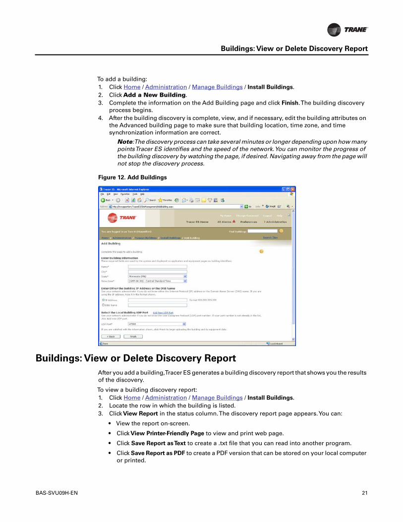
To add a building:1. Click Home / Administration / Manage Buildings / Install Buildings.2. Click Add a New Building.3. Complete the information on the Add Building page and click Finish.The building discovery
process begins.4. After the building discovery is complete, view, and if necessary, edit the building attributes on
the Advanced building page to make sure that building location, time zone, and timesynchronization information are correct.
Note:The discovery process can take several minutes or longer depending upon how manypointsTracer ES identifies and the speed of the network.You can monitor the progress ofthe building discovery by watching the page, if desired. Navigating away from the page willnot stop the discovery process.
Figure 12. Add Buildings
Buildings: View or Delete Discovery Report
After you add a building,Tracer ES generates a building discovery report that shows you the resultsof the discovery.
To view a building discovery report:1. Click Home / Administration / Manage Buildings / Install Buildings.2. Locate the row in which the building is listed.3. Click View Report in the status column.The discovery report page appears.You can:
• View the report on-screen.
• Click View Printer-Friendly Page to view and print web page.
• Click Save Report asText to create a .txt file that you can read into another program.
• Click Save Report as PDF to create a PDF version that can be stored on your local computeror printed.

22 BAS-SVU09H-EN
Building Attributes: View, Edit, Create Custom
To delete the building discovery report and the building discovery entry:1. Click Home / Administration / Manage Buildings / Install Buildings.2. Select the row in which the building is listed.3. Click Delete.
Note: Removing the report or the discovery entry from the list does not delete the buildingfromTracer ES.
Figure 13. Discovery Report
Building Attributes: View, Edit, Create Custom
Overview
Each building has attributes that can help you categorize them or provide placeholders for usefulinformation that might otherwise need to be stored somewhere outside of theTracer ES system.The attribute itself can be thought of as an information category. All buildings will have the sameattributes, but the value assigned to each attribute can vary from building to building.
Tracer ES system uses attributes to:• Locate and communicate with buildings (network attributes)• Define the structure of the home page index• Route alarms by e-mail• Find and list buildings using the Find Buildings search
There are two types of building attributes: standard and custom.

BAS-SVU09H-EN 23
Building Attributes: View, Edit, Create Custom
Standard Attributes are built intoTracer ES System and are automatically assigned to everybuilding:• IP Address or DNS Name - Every recognized object on network has an IP (Internet Protocol)
address, which is a series of numbers, separated by decimals, that tells the network how to findit. An example of a local IP Address is 168.1.1.100. If the building has a DNS Name (the DomainName Server name), it is usually best to use it instead of the IP address. If you are not sure whatto use, contact your network administrator for assistance.
• UDP Port - (User Datagram Protocol) port is the port the system will use to communicate to thebuilding panel.
• Building Information - (Name, City, State, andTime Zone) Required attributes for thebuilding.
• Additional General Attributes - (Address 1, Address 2, Postal Code, Contact Name, Phone
Number, E-mail Address, Graphic Directory, and SiteType). These are not required byTracerES, but you may want to use them.
CustomAttributes are created by administrators or users and added to buildings. It might be usefulto create a custom attribute if the standard attributes do not include information that you wouldlike to gather or use for sorting buildings in the index.
View or Edit
To view or edit building attributes:1. Go to Home / building name / Advanced. Standard attributes are at the top of the list; custom
attributes are at the bottom of the list.2. Click Edit to make changes.3. Make desired changes.4. Click Save.
Create Custom
You can create one of four types of custom attribute:• Two Choices -The value of the attribute can be only one of two choices.Typical examples would
be On or Off,Yes or No, orTrue or False.You must choose the two choices when you createthe attribute (users cannot create their own choices later).
• Fixed Choice List -The same principle asTwo Choices, but you can specify more than two.Examples could be North, South, East,West, or District 1, District 2, District 3.You must chooseall of the available choices when you create the attribute (users cannot create their own valueslater).
• Growing Choice List -The same principle asTwo Choices and Fixed Choice except that a usercan provide an alternate choice of his or her creation. Likewise, subsequent users can selectfrom your original choices or those added later by other users.
• Free Form Value - Users can write in anything they want for this value within number ofcharacters you specify when you create it.

24 BAS-SVU09H-EN
Building Navigation Sidebar
To create a custom attribute:1. Go to Home / Administration / Manage Buildings / Manage Building Custom Attributes.2. Click Add New Building Custom Attribute. A series of steps begins.3. Complete the information on each page until you reach the final page, then click Finish.
Figure 14. Manage building custom attributes
Building Navigation Sidebar
Whenever you are in a building context, that is, when you are looking at something inside of asingle building,* a sidebar menu opens on the left side of the page.You can click on each item inthe sidebar to go to the appropriate page for the building. Some of the links in the sidebar also opensubordinate links.
*Note: Custom graphics that would otherwise be inside of a building context may appearwithout the left navigation.This is an option that can be specified by the graphic creator inTracer Graphics Editor.
Figure 15. Building navigation sidebar

BAS-SVU09H-EN 25
Buildings: Run Reports
Buildings: Run Reports
There are three types of building report:• All Points in Alarm ("Alarm Report") - Lists all of the points in the system that are currently in
an alarm state.• All Points in Override ("Override Report") - Lists all of the points in the system that are currently
being overridden.The list is organized by equipment type and includes the name of the point,the priority level at which it is being overridden, the override value, and the date and time whenit was last overridden.
• Site Commissioning - Lists the names, types, and present values of all of the objects in thebuilding.
To run a report:1. Navigate to Home / building name.2. Click Run Reports.The Run Report popup window appears.3. Select the report type from the list, and then click Run Report.
Buildings: Synchronize Manually
The entireTracer ES database automatically synchronizes with all buildings once per week or otherinterval configured in the System Parameters page.Additionally, you should manually synchronizea building any time you suspect or know that changes were made using a different tool, such asTracer Summit.
To manually synchronize individual buildings:1. Go to Home.2. Click All Buildings.3. Select the buildings you want to synchronize.4. Click Advanced.5. Click Synchronize Now.
Figure 16. Advanced building options

26 BAS-SVU09H-EN
Buildings: Customize Grouping
Buildings: Customize Grouping
You can specify the way buildings are organized on theTracer ES home page in one of three waysaccording to your preference.• No grouping - buildings are listed in alphabetical order.• One grouping level - buildings are grouped by a building attribute of your choice.• Two grouping levels - buildings are grouped by two building attributes of your choice (one
general and one specific).
To customize the building grouping:1. Go to Home / Administration / Global Applications / Customize System Pages / Customize
Building Grouping.The Customize Building Grouping page appears.2. Select the number of index levels.3. Select the general and specific grouping attributes, if required: If you selected one level, select
the general grouping attribute; if you selected two levels, select a general and a specificgrouping attribute.
4. Click Finish.
Figure 17. Customize building grouping
Panel: Reset, Clear RAM, Delete
There are three advanced operations you can perform on building panels: reset the panel, clear thepanel's RAM, and delete the panel.
Reset or Clear RAM
Resetting a panel typically has the same effect as cycling the power for the panel but it could havea different effect depending upon the device manufacturer. Clearing the panel's random accessmemory (RAM) clears out volatile memory.
Note: Reset and clear RAM are enumerations of the ReinitializeDevice BACnet service. ForTrane panels, Reset RAM sets the ReinitializeDevice bit to 0 (Cold Start) and Clear Ram setsthe bit to 1 (Warm Start). Other vendors may have somewhat different interpretations ofthese enumerations.

BAS-SVU09H-EN 27
BACnet Objects and Properties: View, Edit
To reset a panel or clear its RAM:
NOTE:You may need to know the password for the panel.1. Go to Home / building name / Advanced / Panel Reset.2. Select the panel.3. Click Reset. or click Clear RAM.4. Enter the password, if prompted.
Delete
Deleting a panel removes the panel fromTracer ES, but does not remove it from service in thebuilding network.1. Go to Home / building name / Advanced / Panel Reset.2. Select the panel.3. Click Delete.
Figure 18. Panel reset
BACnet Objects and Properties: View, Edit
BACnet objects and properties, as they are defined by the BACnet standard, contain much moreinformation than most users would find useful or practical. Because of the large number of objecttypes and properties that can exist, standard pages inTracer ES use some naming conventions thatare more meaningful to typicalTracer ES users. LikewiseTracer ES does not show objects orproperties that are not useful to typicalTracer ES users. However, some advancedTracer ES usersmay find it useful to be able to see comprehensive and pure BACnet information for advancedtroubleshooting or other unanticipated reasons. The BACnetViewer feature was created for thoseadvanced users.

28 BAS-SVU09H-EN
Panel Communication Alarms: View, Create, Edit, Delete
To view or edit BACnet objects and their properties:1. Go to Home / building name / Advanced / BACnet Viewer.2. Select the type of object you want to view from the list.3. Click Apply. All of the objects of the type you selected appear in the list.4. Click the name of an object to view it.5. If there are editable properties, click Edit to make changes, and then click Save to save them
or Cancel to abandon your changes.
Panel Communication Alarms: View, Create, Edit, Delete
A panel communication alarm is an alarm that you set up in the system to be activated wheneverTracer ES is not able to communicate with the panel. It can also trigger an alarm whencommunication is restored.
To view panel communication alarm:• Go to Home / Administration / Global Applications / Manage Alarm Settings / Manage Panel
Communication Alarms.
To create a panel communication alarm:1. Go to Home / Administration / Global Applications / Manage Alarm Settings / Manage Panel
Communication Alarms.2. Click Create new Communication Alarm. A series of pages begins.3. Complete each page in the series and click Finish at the last page.
To edit a panel communication alarm:1. Go to Home / Administration / Global Applications / Manage Alarm Settings / Manage Panel
Communication Alarms.2. Select an alarm.3. Click Edit. A series of pages begins.4. Complete each page in the series and click Finish at the last page.

BAS-SVU09H-EN 29
Tracer SC Panels: View Directly
To delete panel communication alarms:1. Go to Home / Administration / Global Applications / Manage Alarm Settings / Manage Panel
Communication Alarms.2. Select the alarms.3. Click Delete.
Figure 19. Manage Panel Communication Alarms
Tracer SC Panels: View Directly
If you have anyTracer SC system control panels, you can use the Direct Link to Panel feature inTracer ES to launch theTracer SC software. To be able to access aTracer SC panel in this way, youmust:• be assigned to a user role that has permission to direct link to panel inTracer ES.To enable a
user role to direct link toTracer SC panels, create a new user role or edit an existing role withtheYes selected forTracer SC under Direct Link to Panel.
• have a user name and password for theTracer SC panel you want to view.To acquire a username and password for theTracer SC panel, contact the administrator for the controller.
To directly link to aTracer SC panel:1. Go to Home / building name.2. Locate and click the Direct Link Icon ( ) next to Summary.You can also find and click the icon
on several other pages including priority mapping, schedules, equipment and subsystemswithin the building. A small popup window appears with one or more underlined links, eachrepresenting a differentTracer SC controller.
3. Click the appropriate underlined link.4. Wait for the browser to open theTracer SC interface in a new window.5. Log in toTracer SC. See theTracer SC help for more information.
BCU Phone Book: View, Edit
Each BCU can have up to two modems that it uses for alarm notification. Each modem can beconfigured independently with its own dialing settings and its own list of (alarm recipeints') phonenumbers, known as a "BCU Phone Book."You can useTracer ES to view and edit the dialing settingsfor each modem, and to add, edit, or delete entries in the BCU Phone Book.

30 BAS-SVU09H-EN
NavigationTree: Use, Edit, Backup, Restore
To view the BCU Phone book:1. Go to Home / building name / Advanced / BCU Phone Book.The BCU Phone Book page lists
the names and Device IDs of the modems.2. Click the name of a modem to go to the BCU Phone Book page for the modem.
To edit a BCU Phone book:1. Go to the BCU Phone Book page for the modem.2. Click Edit BCU Phone Number to make changes to the dialing information (the Dialing Prefix
and Calling Card number) that can be used by alarm recipients in the phone book.3. Select an alarm recipient and click Delete to move it or click Edit to make changes. Changes can
include the alarm recipient type, name, phone number, or whether or not the dialing prefix orcalling card number are used for the recipient.
NavigationTree: Use, Edit, Backup, Restore
The building navigation tree is a faster, customizable way for you to navigate through the contentsof a building. The tree appears at the top of the building navigation sidebar.
To use the building navigation tree:1. Go to Home / Building Name.2. Click NavigationTree. The tree appears in a small, attached window. If it has not been edited,
the tree is organized according to the building navigation sidebar.
• Use the + and - signs to show and hide the children in the tree.
• Click on the name of an element in the tree to go to the desired location.
You can use the tree editor to do the following:• Edit the items in the tree, the way they are organized, custom graphics that are assigned them.• Backup the tree to a file. This provides a convenient way for you to restore the tree in the event
of unexpected or unwanted changes.• Restore a tree to an earlier backup file.
To edit the tree:1. Go to Home / Building Name / Advanced /Tree Editor.2. Use the buttons underTree Functions to make changes to items in the tree.3. Click Save when finished.
To backup the existing tree:1. Go to Home / Building Name / Advanced /Tree Editor.2. Click Backup. The tree is saved to a predetermined location on theTracer ES server and named
according to the building name, date, and hour of the backup.

BAS-SVU09H-EN 31
Custom Pages: Assign to Building
To restore the tree from an earlier backup:1. Go to Home / Building Name / Advanced /Tree Editor.2. Click Restore.The Restore NavigationTree window appears.3. Select the backup file from which you want to restore the tree. The backups are named
according to the building name, date, and hour of the backup. If more than one backup wasmade within the same hour, each will have the same name in the list. More recent backup filesappear closer to the top of the list.
4. Click Restore.
Figure 20. NavigationTree Editor
Custom Pages: Assign to Building
If you have custom XML pages that were created forTracer Summit, and they have been convertedfor use withTracer ES and copied to theTracer ES server, the final step is to assign them to thebuilding inTracer ES.

32 BAS-SVU09H-EN
To assign a custom page to a building:1. Go to Home / Building Name.The building summary page appears.2. Click Define Custom Pages for Building.The Define Custom Pages for Building popup window
appears.3. Select a custom page for Change to this Building Customization.4. Click Save.
Figure 21. Define custom pages for building
Alarms
Alarms: View, Acknowledge, Remove
The alarm handling capabilities ofTracer ES system permit users to receive, view, acknowledge,and make comments on building alarms. Administrative users can also manage alarm settingssuch as priority mapping, notification classes, E-mail routing, ignored alarm rules, panelcommunication alarms, and BACnet device alarm subscriptions.
Viewing -Tracer ES system receives alarm messages from building control panels and displaysthem in theTracer ES Alarm log.The system can also notify recipients by E-mail and SMS textmessage, depending upon network configuration.
To view all system alarms:• Click All Alarms (from any page).
To view the alarms for a single building:1. Go to Home / building name.2. Click Alarms on the sidebar.
Note: If new alarms are received while you are viewing the building alarms list, a messageappears stating that there are new alarms and includes a link for refreshing the alarm list.
To view alarms for a specific building panel:1. Go to Home / building name.2. Click Alarms on the sidebar.3. ClickView Panel Alarms.The list includes all of the alarms that originate from the panel or are
routed to the panel from other devices.

BAS-SVU09H-EN 33
Alarms: View, Acknowledge, Remove
Acknowledging - Many alarms are configured in their building panels to require useracknowledgement. If they are not acknowledged, they will continue to be broadcast in the systemand they may also be sent electronically to specific users or administrators. Alarms can beacknowledged locally, or they can be acknowledged usingTracer ES system. In any case, when thealarm is acknowledged, the user’s name and the panel’s local time and date are recorded inTracerES system for other users to see.
To acknowledge alarms:1. Follow the steps above to view the alarms.2. Select one or more alarms.3. Click Acknowledge.
Note: IfTracer ES system is unable to acknowledge an alarm, a failure notificationwill appear.
Removing - Removing an alarm inTracer ES system makes the alarm invisible to allTracer ES users.However, the alarm record still remains in the alarm log database unless it is removed by a SQLserver administrator.
To remove alarms:1. Click All Alarms (from any page).2. Select one or more alarms.3. Click Delete.
Figure 22. All Alarms

34 BAS-SVU09H-EN
Alarms: Advanced Search (and Remove)
Alarms: Advanced Search (and Remove)
Over time,Tracer ES can accumulate a large number of alarms in the alarm log. In some cases,there can be thousands, or even tens of thousands of them.The vast majority of the alarms in atypical alarm log can be removed because they are out of date, unimportant, or no longerapplicable. The Advanced Search function permits you to search for, and remove large numbersof alarms very quickly.
Note:The ability to use the Advanced Search feature can be enabled or disabled accordinguser role assignment. If you do not see the link for Advanced Search and Remove, you areassigned to a role that cannot perform the advanced search and removal.
To use the Advanced Search feature for all alarms (across buildings):
Click All Alarms (from any page) or go to Home / building name /Alarms.
1. Click Advanced Search.The Advanced Search page appears.2. Use the controls on the page to select arms you want to view or remove.3. Click Remove. A popup message appears and must be acknowledged before alarms are
permanently removed.
NOTE: Only the top 100 alarms of those selected can be shown at one time.The sort orderdetermines which alarms are at the top. Clicking Remove will remove all selected alarms,including those that you cannot see, but meet the search criteria.
Alarm Comments: View or add
Tracer ES can store user comments for each alarm that posts to the system.This permits users tokeep a running dialog of the status of an alarm, its causes, or other information that keeps everyoneinformed during a potentially urgent situation. All alarm comments are retained in the database.

BAS-SVU09H-EN 35
Alarms: Ignoring
To view or add alarm comments:1. Go to the page containing the alarm (Home / All Alarms / or Home / Building Name).2. Locate the alarm you are interested in. If comments have been left by you or another user, there
will be a link in the Comment column.3. Click the link.The User Comments page appears. Each comment includes the (user) profile that
was used to create it and the date and time the comment was left.4. To add your own comments, type them into the Comment field and click Save.
Figure 23. User comments
Alarms: Ignoring
You can ignore alarms inTracer ES. Doing so does not alleviate the cause of the alarm but willprevent the alarm from posting repeatedly to the system. By ignoring an alarm, you are effectivelycreating a rule in the system telling it to always ignore a particular alarm from a particular sourceor a particular type of alarm from all sources.
Note: Ignored alarms affect all users in the system. If one user ignores an alarm, no otheruser will receive notification of it.
To ignore an alarm and create an ignored alarm rule:1. Go to Home / All Alarms.2. Locate and select the alarm you want to ignore.3. Click Ignore.The Permanent Alarm Filtering popup window appears.4. Read the popup window and make a choice, then click Save.Your choice will be applied to the
system unless or until the rule is deleted.
Ignored Alarm Rules: View or Delete
You can view a list of all alarm types that are being ignored in the system and delete the rules ifdesired, which permits the alarms to post to the system again.

36 BAS-SVU09H-EN
Alarm Priority Levels and Alarm Notification Classes: Edit
To view or delete an ignored alarm rule:1. Go to Home / Administration / Global Applications / Manage Alarm Settings / Manage Ignored
Alarm Rules. All of the ignored alarm rules are shown in the list.2. Locate and select the rule you want to delete.3. Click Delete. A confirmation window appears.4. Read and respond to the confirmation window.
Figure 24. Manage ignored alarm rules
Alarm Priority Levels and Alarm Notification Classes: Edit
You can provide your own notification class names for classes 5-20. Notification classes 1-4 arenamed by default and cannot be changed.The name you provide should indicate the type andseverity of the alarm it indicates. Descriptive names will be useful for mapping the alarm prioritiesto your control panels.

BAS-SVU09H-EN 37
Alarm Priority Levels and Alarm Notification Classes: Edit
To change the alarm notification classes:1. Go to Home / Administration / Global Applications / Manage Alarm Settings / Manage
Notification Classes.2. Type in a new name for each priority you want to change.3. Click Save.
Figure 25. Manage notification classes

38 BAS-SVU09H-EN
Alarm Priorities: Mapping
Alarm Priorities: Mapping
Notification classes must be defined to enableTracer ES to notify the intended recipients ofbuilding alarms in the most efficient manner possible.Tracer ES supports as many alarmnotification classes as needed for each panel type.• Non-Trane BACnet panels can have up to 256 alarm priority levels.The building priority level
is specified by the Notification Class or Event Enrollment objects that are associated with thealarm event. InTracer ES, by default, alarms from all priority levels map to Service Requiredalarm notification class.
• Trane BCUs use 20 alarm priority levels, numbered 1 through 20. InTracer ES, by default, alarmpriorities 1 through 4 map to (1) No Alarm, (2) Informative/Advisory, (3) Service Required, and(4) Critical.
• TraneTracker panels (version 10 and later) have three BACnet alarm priority levels, numberedEvent Class 2 through 4. InTracer ES, by default, these alarm priorities map to (Event Class 2)Informative/Advisory, (3) Service Required, (4) Critical.
Notes:To receive alarms fromTracker panels, theTracer ES system must be configured inthe building control panel as a recipient of alarms with theTracker service tool.Theworkstation ID of theTracer ES system must match the workstation ID used in theprogramming of theTracker alarm event receiver for theTracer ES system to receiveTrackeralarms. See table below.To receive alarms fromTrackerVersion 12 or higher panels,TracerES will "register foreign" with the building control panel during the building discoveryprocess.
Workstation number
Workstation ID
1 822 833 844 855 866 877 888 899 9010 91

BAS-SVU09H-EN 39
Alarm E-mail and SMSText MessageTemplates: View, Create, Delete, Assign
To map alarm priority levels to notification classes:1. Go to Home / Administration / Global Applications / Manage Alarm Settings / Manage Priority
Mappings.2. Select theTracer ES alarm priority levels for each panel priority level you want to define.3. Click Finish. The new priority levels will be applied immediately to existing and new panels of
the type specified, but alarms received before the change will not be affected.
Figure 26. Manage priority mapping - BCUs
Alarm E-mail and SMSText MessageTemplates: View, Create, Delete,
Assign
You can create templates that define the format and content of alarm message notifications. Eachalarm message recipient can then be assigned two of the templates: one for alarm messagesreceived by e-mail and one for alarm messages received by SMS text message.There are severalreasons why you might want to create message templates:• The level of expertise or responsibility of the message recipient• Limited screen size on some mobile devices may make long messages difficult to use• SMS text messages are limited to 160 characters• The language spoken by the message recipient
There is no practical limit to the number of templates that can be created and saved.
To view or delete alarm E-mail and SMS text message templates:• Go to Home / Administration / Global Applications / Manage Alarm Settings / Manage Alarm
MessageTemplates. All of the alarm message templates are listed.
• To view, click the name of the template. (You can also edit the template if you make changesand click Save.)
• To delete, select the template and click Delete.

40 BAS-SVU09H-EN
Alarm Panel Subscriptions: Managing
To edit an alarm E-mail or SMS text message template:1. Go to Home / Administration / Global Applications / Manage Alarm Settings / Manage Alarm
MessageTemplates.2. Click the name of the template.The Edit Alarm MessageTemplate page appears.3. Complete the fields in the pop-up window and click Save.
To create alarm E-mail and SMS text message templates:1. Go to Home / Administration / Global Applications / Manage Alarm Settings / Manage Alarm
MessageTemplates.2. Click Add New Alarm MessageTemplate.The Create Alarm MessageTemplate page appears.3. Complete the fields in the pop-up window and click Save.
To assign an alarm message template to a user, do one of the following:• Go to Home / Administration / Global Applications / Manage Alarm Settings / Manage Alarm
MessageTemplates, select a template, and then click Assign.• Go to Home / Administration / Manage User Profiles and Roles / Manage User Profiles, select
a current user or create a new user, and then specify the template name in theTemplate for SMSText Alarm Messages orTemplate for E-mail Alarm Messages field.
• Go to Home / Administration / Global Applications / Manage Alarm Settings / Manage E-mail
Addresses.
Alarm Panel Subscriptions: Managing
You can set up subscriptions inTracer ES so that the system receives alarms according to selectednotification classes from specified equipment. A single subscription can contain multiple panelsand a number or range of notification classes.
Note: Many devices do not support all of the alarm notification classes, or they may alreadybe at the maximum number subscriptions for a particular class. There is no way inTracerES to know in advance that a class is unavailable, but you will see an error message if youattempt to subscribe to unavailable classes.The alarm subscriptions table accuratelyreflects which alarm notification classes are successfully subscribed. If you have completedthe steps below, and an alarm notification class is absent from the table, it was unavailablefor subscription.
To set up a subscription:1. Go to Home / Administration / Global Applications / Manage Alarm Settings / Manage Panel
Alarm Subscriptions.
2. Select panel names from the list and click Subscribe.The Subscribe to Panel Alarm pageappears.
3. Specify which notification classes you would like to subscribe to in the Classes field.You canspecify each class individually, separated by commas (1, 3, 9), indicate a range using a hyphen(11-13, which includes 11, 12, and 13), or use a combination (1, 3, 9, 11-13).
4. Click Save.You will be returned to the updated ManageTracer ES Alarm Subscriptions page.

BAS-SVU09H-EN 41
E-mail and SMSText Message Routing: Setup Server
To edit a subscription:1. Go to Home / Administration / Global Applications / Manage Alarm Settings / Manage Panel
Alarm Subscriptions.
2. Select panel names from the list and click Edit.The Subscribe to Panel Alarm page appears.3. In the Classes field, edit the numbers so that they represent the notification classes you want
to subscribe to.4. Click Save. On the ManageTracer ES Alarm Subscriptions page, the notification classes that
were successfully subscribed to will appear in the Subscriptions column for the selectedpanels.
Figure 27. Managing Alarm Subscriptions
To delete subscriptions:1. Go to Home / Administration / Global Applications / Manage Alarm Settings / Manage Panel
Alarm Subscriptions.
2. From the list, select panel names and click UnSubscribe. A confirmation window appears.3. Read and respond to the confirmation window. "None" will appear in the Subscriptions column
for the selected panels on the ManageTracer ES Alarm Subscriptions page.
E-mail and SMSText Message Routing: Setup Server
Tracer ES alarm e-mail and SMS text message delivery requires that an SMTP-compliant mailserver is present and functioning on the IT network.Tracer ES does not send e-mail and SMS textmessages directly; it uses the existing mail server to deliver the messages. For informationregarding the installation and configuration of mail servers, contact your IT department.

42 BAS-SVU09H-EN
Alarm E-mail and SMSText MessageTemplates: View, Create, Delete, Assign
To setup the e-mail and SMS text message routing:1. Go to Home / Administration / System Maintenance / System Parameters.2. Click Edit.3. Make changes to the E-mail Server Parameters to enableTracer ES to use an existing e-mail
account.
Note: If an e-mail recipient replies to theTracer ES alarm e-mail, theTracer ES mail serviceresponds as defined by e-mail server—configured by your IT department.TheTracer ESsystem has no control over the configuration of these mail client parameters. Whether theTracer ES mail profile is used as a send-only function and incoming e-mails are ignored ora user routinely checks theTracer ES profile inbox for status on alarms sent to contractorsor other personnel is determined by your IT department and/or localTrane representative.
Figure 28. System parameters - E-mail server parameters
Alarm E-mail and SMSText MessageTemplates: View, Create, Delete,
Assign
You can create templates that define the format and content of alarm message notifications. Eachalarm message recipient can then be assigned two of the templates: one for alarm messagesreceived by e-mail and one for alarm messages received by SMS text message.There are severalreasons why you might want to create message templates:• The level of expertise or responsibility of the message recipient• Limited screen size on some mobile devices may make long messages difficult to use• SMS text messages are limited to 160 characters• The language spoken by the message recipient
There is no practical limit to the number of templates that can be created and saved.
To view or delete alarm E-mail and SMS text message templates:• Go to Home / Administration / Global Applications / Manage Alarm Settings / Manage Alarm
MessageTemplates. All of the alarm message templates are listed.
• To view, click the name of the template. (You can also edit the template if you make changesand click Save.)
• To delete, select the template and click Delete.

BAS-SVU09H-EN 43
E-mail Addresses for Alarm Routing: Add, View, Edit, Delete
To edit an alarm E-mail or SMS text message template:1. Go to Home / Administration / Global Applications / Manage Alarm Settings / Manage Alarm
MessageTemplates.2. Click the name of the template.The Edit Alarm MessageTemplate page appears.3. Complete the fields in the pop-up window and click Save.
To create alarm E-mail and SMS text message templates:1. Go to Home / Administration / Global Applications / Manage Alarm Settings / Manage Alarm
MessageTemplates.2. Click Add New Alarm MessageTemplate.The Create Alarm MessageTemplate page appears.3. Complete the fields in the pop-up window and click Save.
To assign an alarm message template to a user, do one of the following:• Go to Home / Administration / Global Applications / Manage Alarm Settings / Manage Alarm
MessageTemplates, select a template, and then click Assign.• Go to Home / Administration / Manage User Profiles and Roles / Manage User Profiles, select
a current user or create a new user, and then specify the template name in theTemplate for SMSText Alarm Messages orTemplate for E-mail Alarm Messages field.
• Go to Home / Administration / Global Applications / Manage Alarm Settings / Manage E-mail
Addresses.
E-mail Addresses for Alarm Routing: Add, View, Edit, Delete
Alarms can be routed to the e-mail addresses of existingTracer ES users with user IDs, or they canbe routed to e-mail addresses for non-users who do not have aTracer ES User ID. For instancemaintenance people in the field who can be reached on their handheld device, such as a PDA.
To add non-user e-mail addresses routing alarms:1. Go to Home / Administration / Global Applications / Manage Alarm Settings / Manage E-mail
Addresses.2. Click Add New E-mail Address.The Add E-mail Address pop-up window appears.3. Complete the fields in the popup window and click Save.
• Verify the E-mail Address field contains a valid e-mail.
• The Description field can be any text (It will appear in the Description column withTracer ESusers' names).
• Template should be set to Default if the recipient uses a regular desktop or laptop computeror to PDA if they are using a handheld device with limited text display capabilities.
To view or edit non-user e-mail addresses:1. Go to Home / Administration / Global Applications / Manage Alarm Settings / Manage E-mail
Addresses. All of the e-mail addresses and related information is shown.2. Select an address and click Edit to make changes.The Edit E-mail Address pop-up window
appears.3. Change the fields in the popup window as desired and click Save.

44 BAS-SVU09H-EN
To delete non-user e-mail addresses:
Note: you cannot deleteTracer ES users from this page.You can only delete them from theManage User Profiles screen.
1. Go to Home / Administration / Global Applications / Manage Alarm Settings / Manage E-mail
Addresses.2. Select the addresses you want to delete.3. Click Delete.
Figure 29. Manage E-mail addresses
Alarm E-mail Routing Rule: Create, Edit, View, Delete
An alarm e-mail routing rule lets you route alarms by building and priority level to e-mail recipients(including users with mobile handheld devices, if they are able to receive e-mail messages) of yourchoosing. For instance, you could route high priority alarms to on-call staff so they can respondquickly to problems.The recipients for alarm notifications can includeTracer ES users with an e-mail address already in the system on their user profile pages, or other non-users whose e-mailaddress and other information is added only in the alarm routing section.
Notes:Tracer ES users cannot receive e-mail notifications of alarms in buildings to which they donot have access.If you are working on a rule that applies to a single building, you will not see addresses forusers who do not have access to the building, and users without access to the building canonly be added if they are given access to the building by editing their user profile.
To create an alarm E-mail routing rule:1. Go to Home / Administration / Global Applications / Manage Alarm Settings / Manage E-mail
Routing or Home / All Buildings, then select buildings and click Route Alarms.2. Click Add new E-mail Routing Rule. A series of pages begins.3. Complete each page in the series and click Finish at the last page.

BAS-SVU09H-EN 45
Audible Alarms: Setup
To view or edit an alarm E-mail routing rule:1. Go to Home / Administration / Global Applications / Manage Alarm Settings / Manage E-mail
Routing.2. Click the name of the rule. A series of pages begins.3. Scroll through the pages to view the rule details or make changes and click Finish at the last
page.
To delete alarm E-mail routing rules:1. Go to Home / Administration / Global Applications / Manage Alarm Settings / Manage E-mail
Routing.2. Select the rules.3. Click Delete.
Figure 30. Manage E-mail routing
Audible Alarms: Setup
Tracer ES can store can emit an audible sound on a user's computer if an alarm occurs while theuser is logged in.You can enable or disable the audible alarm feature and specify the sound filethat is used to make the sound on the System Parameters page.
To setup audible alarms:• Go to Home / Administration / System Maintenance / System Parameters and edit the system
parameters.

46 BAS-SVU09H-EN
Scheduling Overview
Schedules
Scheduling Overview
The scheduling application inTracer ES overlays the native scheduling capabilities of the individualbuilding control panels. When you create, edit, or delete schedules inTracer ES, your changes arestored inTracer ES and sent to the building panels as quickly as necessary. You can use theTracerES scheduling application to complete the following building-level tasks:• Create, view, and edit normal schedules.• Create, view, edit, and cancel exception schedules.• Create, view, edit, delete, and assign schedule attributes.• Create, view, edit, delete, and apply exception templates.• Activate or Deactivate the emergency schedule.• View panel schedules.
In addition to the building-level scheduling capabilities, you can useTracer ES global schedulingabilities to make global changes to schedules and to create, view, edit, or delete the emergencyschedule.
Note:Tracer ES does not recognize holidays as a separate schedule type. Use exceptionschedules to create holidays.
It is possible to useTracer ES andTracer Summit (or other tools) to manage the same buildingschedules simultaneously, but doing so is not recommended. Trying to use two or more differenttools to manage the same panel database could create confusion and cause unwanted results. Itis a best practice to insist that your users and administrators only useTracer ES for schedulemanagement.
Normal Schedule: Create, View, Edit
A Normal schedule is also known as a time of day schedule. It is the schedule that is used on aregular basis and under normal circumstances. Normal schedules can be of type HVAC, Lighting,Set Analog, Binary or Multistate. Binary and Multistate schedules are valid only in BACnet-compliant controllers. HVAC schedules are valid only forTracer Summit BCU orTracker schedules.Lighting schedules are valid only forTracer Summit BCU schedules.
To create a normal schedule:1. Go to Home / building name / Schedules / Normal.2. Click Create New Schedule. A series of pages begins.3. Complete the series of pages and click Save.

BAS-SVU09H-EN 47
Exception Schedule: Create, View, Edit, Cancel
To view and edit normal schedule:1. Go to Home / building name / Schedules / Normal.2. Click the name of the schedule.The schedule summary page contains all viewable information
about the schedule.3. To edit the schedule, click Edit Name, Edit Schedules, or Edit Dates and Events.4. Make changes to the page as desired.5. Click Save.Your changes are saved and should be reflected on the summary page.6. Repeat steps 3 to 5 for additional changes.
Figure 31. Manage normal schedule
Exception Schedule: Create, View, Edit, Cancel
An exception schedule is a temporary schedule that is applied to a normal schedule for specifieddays. Exceptions can be used for holidays or other occasions that require an extension, reduction,or other change to typical building operation.The start date is always defined and the end date istypically defined, but not required.
To create an exception schedule:1. Go to Home / building name / Schedules / Exceptions.2. Click Create New Exception Schedule. A series of pages begins.3. Complete each page in the series and click Save at the last page.
To view and edit an exception schedule:1. Go to Home / building name / Schedules / Exceptions.2. Click the name of the schedule.The exception schedule summary page contains all viewable
information about the exception.3. To edit the exception schedule, click Edit Name, Edit Schedules, or Edit Dates and Events.4. Make changes to the page as desired.5. Click Save.Your changes are saved and should be reflected on the summary page.6. Repeat steps 3 to 5 for additional changes.

48 BAS-SVU09H-EN
Schedule Attributes: Create, View, Rename, Delete, Publish, Assign
To cancel exception schedules (and delete them from the system):1. Go to Home / building name / Schedules / Exceptions.2. Select one or more exception schedules.3. Click Cancel.The exceptions schedules are no longer being used and are deleted from the
system.
Figure 32. Manage exception schedules
Schedule Attributes: Create, View, Rename, Delete, Publish, Assign
Schedule attributes are a tool that can make it easier for you to locate or identify schedules withsome property in common. You can create attributes with a name of your choosing. Afterattributes are created they must be published to make them available in the system. After they arepublished, an attribute can be assigned to one or more schedules. When schedules are listed intables, such as in the global scheduling application, one column of the table contains scheduleattributes, permitting you to sort the table on attribute values.
To create a schedule attribute:1. Go to Home / Administration / Global Applications / Manage Schedule Settings / Manage
Schedule Attributes.2. Click Add New Schedule Attribute.TheTracer ES Schedule Attribute pop-up window appears.3. Type a name for the new attribute in the New Attribute Name field.4. Click Save.
To view or rename a schedule attribute:1. Go to Home / Administration / Global Applications / Manage Schedule Settings / Manage
Schedule Attributes. All the schedule attributes, their published status, and the assignmentstatus are shown.
2. To rename an attribute, click its name. TheTracer ES Schedule Attribute pop-up windowappears.
3. Type a name for the new attribute in the New Attribute Name field.4. Click Save.

BAS-SVU09H-EN 49
Schedule Attributes: Create, View, Rename, Delete, Publish, Assign
To publish schedule attributes and make them available for assignment:1. Go to Home / Administration / Global Applications / Manage Schedule Settings / Manage
Schedule Attributes. Attributes that have not already been published contain a No in thePublished column of the table.
2. Select the schedule attributes.3. Click Publish.
Deleting an attribute removes it from the list and automatically removes its assignment from anyschedules.
To delete schedule attributes:1. Go to Home / Administration / Global Applications / Manage Schedule Settings / Manage
Schedule Attributes.2. Select the schedule attributes.3. Click Delete.
To change assignment of one attribute to one or more schedules:1. Go to Home / building name / Schedules /Attributes. A table appears showing all the published
attributes and the normal schedules assigned to them.2. Select the attribute.3. Click Edit.The Assign Schedule Attributes page appears.4. Select the desired schedules from the Available Schedules and Selected Schedules lists and
click the Add or Remove buttons to assign them as desired. Schedules in the SelectedSchedules list will be assigned to the named schedule attribute.
5. Click Save.
To change assignment of one schedule to one or more attributes:1. Go to Home / building name / Schedules. A list of all of the building schedules appears.2. Click the name of the schedule.The schedule summary page appears.3. Click Edit Attributes.The Edit Normal Schedule - Attributes page appears.4. Select the desired schedule attributes from the Available Attributes list and Selected Attributes
lists and click the Add or Remove buttons to assign them as desired. Schedule Attributes in theSelected Attributes list will be assigned to the named schedule.
5. Click Save.
Figure 33. Manage schedule attributes

50 BAS-SVU09H-EN
Emergency Schedule: Create, View, Edit, Activate, Deactivate
Emergency Schedule: Create, View, Edit, Activate, Deactivate
The emergency schedule is a preconfigured exception template that allows building operators to"one-click" apply exceptions to all pertinent schedules in a building in the event of a "snow day" orsimilar "emergency" day. All exception events are applied simultaneously. The emergencyschedule can be applied to one or more building schedules in one or more buildings. Theemergency schedule can be used for any purpose, but it is intended to be a way to easily putspecified schedules into a limited or unoccupied mode in the event of an emergent situation, suchas building closure due to weather. Typically lighting and occupied periods on HVAC scheduleswould be shortened or eliminated in the emergency schedule. Likewise, a set analog or lightingschedule would be set to values appropriate for the desired effect on building operation.
To create the emergency schedule:1. Go to Home / Administration / Global Applications / Manage Schedule Settings / Manage
Emergency Schedules.The Emergency Schedule Summary page appears.2. Click Add Events. A series of pages begins. The pages permit you to create events for each
schedule type.
Note: If the emergency schedule has already been created, there will be an Edit buttoninstead of an Add Events button. See the emergency schedule editing instructions.
3. Complete each page in the series and click Save at the last page.
To view or edit the emergency schedule:1. Go to Home / Administration / Global Applications / Manage Schedule Settings / Manage
Emergency Schedules.The Emergency Schedule Summary page shows the building andschedule names that would be affected by the emergency schedules if they were activated.
2. Click Edit. A series of pages begins. The pages permit you to view, create, or modify eventsfor each schedule event type and include or exclude individual buildings and schedules.
Note: If the emergency schedules have not been created, there will be anAdd Events buttoninstead of an Edit button. See the emergency schedule creating instructions.
3. View or make changes to each desired page.4. Click Save at the last page.

BAS-SVU09H-EN 51
ExceptionTemplate: Create, View, Edit, Delete, Apply
To activate or deactivate the emergency schedule for one or more buildings:1. Go to Home / All Buildings.The building list page appears. Note that there is a column in the
table indicating whether or not any buildings have the emergency schedule activated.2. Select the buildings for which you want to activate the emergency schedule.3. ClickActivate to activate the emergency schedule for the selected buildings or click Deactivate
to deactivate the emergency schedule for the selected buildings. The emergency schedule willstay active or inactive for the selected building until changed by a user.
Note:You can also activate or deactivate the emergency schedule for a single building bygoing to the individual building summary page. However, the Emergency ScheduleActivate and Deactivate buttons will only appear if the building is selected in the EmergencySchedule.
Figure 34. Emergency schedule summary
ExceptionTemplate: Create, View, Edit, Delete, Apply
An exception template is a set of predefined scheduling events that are named and saved forsubsequent or repeated use in future exceptions. These can be useful if you have irregularlyscheduled activities that change the occupancy of an area or space at a predictable time andduration. For instance, if a particular conference occurs several times per year at different locationsbut outside of the normal occupied hours you could create an exception template called"Conference" and apply it as needed each time the conference is scheduled to the area in which theconference will be held.
To create an exception template::1. Go to Home / Administration / Global Applications / Manage Schedule Settings / Manage All
ExceptionTemplates.2. Click Create a New ExceptionTemplate.The Create ExceptionTemplate page appears.3. Create each exception event by defining the event type and start and stop times where
applicable, and clicking Add for each.4. Click Finish after all events are added.

52 BAS-SVU09H-EN
ExceptionTemplate: Create, View, Edit, Delete, Apply
To view and edit an exception template:1. Go to Home / Administration / Global Applications / Manage Schedule Settings / Manage All
ExceptionTemplates.2. Click on the name of the exception template.The ExceptionTemplate Summary page appears
containing all viewable information about the exception template.3. Click Edit to edit template.4. Make changes to the events in the template as desired.5. Click Save.
To delete exception templates:1. Go to Home / Administration / Global Applications / Manage Schedule Settings / Manage All
ExceptionTemplates.2. Select the exception templates.3. Click Delete.The exception templates will no longer appear in the list, but deleting the template
has no effect on any exceptions previously created by applying it.
To apply an exception template:1. Go to Home / Administration / Global Applications / Manage Schedule Settings / Manage All
ExceptionTemplates.2. Select the exception template.3. Click Apply. A series of pages begins.4. Complete each page in the series and click Finish at the last page.
Figure 35. Manage all exception templates

BAS-SVU09H-EN 53
Schedule Events Color Coding
Every schedule must have at least one event, but it can also have numerous events. To assist youin distinguishing one type of event from others each type has its own color scheme:• Orange/Light Orange: Occupied/Unoccupied or Binary On/Off• Light Gray with hash marks: Optimal start/stop• Gray: Night Economize period in HVAC schedule• Yellow/LightYellow: Lighting Start/Stop• Tan: Analog• Green/Light Green: Multistate (different states)• White: Release
Figure 36. Schedule color coding
Panel Schedules: View
Typically, the scheduling application inTracer ES sees and manipulates scheduling information asit exists in theTracer ES database. Once your changes are completed,Tracer ES writes the changesto the building panels in a format they can use to execute the schedule. As a result, what you seeinTracer ES can look different than what appears if you look directly in the building panel.
To help you confirm that the resulting schedules in the building panels are what you expect themto be (or to make sure that your changes were actually written to the building panels), you can useTracer ES to look at the panel schedules as they appear in the panel database.

54 BAS-SVU09H-EN
Global Schedule Changes
To view panel schedules:1. Go to Home / Building Name.2. Click Schedules.3. Click View Panel. A list of schedules appears in a table.4. Click the schedule you want to view. The schedule appears as a list of events.5. Click Previous or Next to see past or future schedules.
Note: Because of limited storage capabilities of building panels, schedule exceptions maynot be shown in the panel schedule. These events will be written down fromTracer ES asneeded.
Note: Exceptions marked "(Non-TES)" were created inTracer Summit.
Figure 37. View panel schedules
Global Schedule Changes
You can use theTracer ES global change functionality to change multiple schedulessimultaneously. The schedule changes can be applied to one schedule type (HVAC, lighting, or setanalog) at a time. To make changes to multiple schedule types, perform a global change asdescribed once for each type.
To make global schedule changes:1. Go to Home / All Buildings.2. Select the buildings containing the schedules you want to change.3. Click Global Changes.The Global Changes page appears.4. Click Change Schedules. A series of pages begins.5. Complete each page in the series and click Finish at the last page.

BAS-SVU09H-EN 55
Completed Reports: View, E-mail, or Delete
Reports
Completed Reports: View, E-mail, or Delete
Completed reports are reports that have been generated based on a custom report definition.Custom reports capture data at a particular point in time - when the report was run eithermanually or systematically by Tracer ES.
To access completed reports:1. Click Reports (from any page).2. Click Completed Reports.
View Completed Reports
To view completed reports:1. Click Reports (from any page).2. Click Completed Reports.3. Click the report name to view the report in PDF format.
E-mail Completed Reports
To e-mail custom reports:1. Click Reports (from any page).2. Click Completed Reports.3. Select one or more reports and click4. Send E-mail.5. Enter a Subject and Body for the e-mail.6. Select theTracer ES Users to receive the e-mail. Select the user name and click Add.7. To send reports via e-mail to non-Tracer ES users, enter the e-mail addresses in the Add
Additional E-mail Recipients box.8. Click Send.
Reports: Create, Modify, and Import Custom Reports
The Tracer ES Report Designer allows you to create meaningful, customized reports withminimal effort. You select the system, building, and equipment data point(s), set timeparameters, and add graphics and text to the report.
To access the Report Designer to create a new report:1. Click Reports (from any page).2. Click Custom Reports.3. Click Create New Report.
To modify an existing report:4. Click Reports (from any page).5. Click Custom Reports.6. Click on the report name.

56 BAS-SVU09H-EN
Reports: Create, Modify, and Import Custom Reports
Report Set Up
Select the Canvas Size for your report and page layout (portrait or landscape).
Adding Content to Reports
The Report Canvas in the middle of your screen is where you arrange report elements.Individual elements can be resized by dragging their borders or moved by clicking and dragging.

BAS-SVU09H-EN 57
Reports: Create, Modify, and Import Custom Reports
The tool palette on the left-hand side of the screen allows you to add elements to your report bydragging them onto your canvas. Elements and their associated properties are described below.Click each element to view further details.• Bar Graph
• Line Graph
Bar Graph PropertiesType Property DescriptionData Chart Title Enter a title for the chart.
Data Source/Y Axis Select data source(s) for the graph's Y axis. Click Apply.
X Axis Scale Select the time scale (hours, days, weeks, months, or years)
Report Period Select a predefined time period or click Custom Date Range to define a time period.
Format Chart Title Select the text Format:• Font• Font Size• Boldface• Italics• Alignment
X and Y Axis Labels Select the text Format:• Font• Font Size• Boldface• Italics• Alignment
Legend Text Select the text Format:• Font• Font Size• Boldface• Italics• Alignment
Series Colors Pick a color for each series.
Line Graph PropertiesType Property DescriptionData Chart Title Enter a title for the chart.
Data Source/Y Axis Select data source(s) for the graph's Y axis. Click Apply.
X Axis Scale Select the time scale (hours, days, weeks, months, or years)
Report Period Select a predefined time period or click Custom Date Range to define a time period.
Format Chart Title Select the text Format:• Font• Font Size• Boldface• Italics• Alignment

58 BAS-SVU09H-EN
Reports: Create, Modify, and Import Custom Reports
• Data Value
• Table Value
X and Y Axis Labels Select the text Format:• Font• Font Size• Boldface• Italics• Alignment
Legend Text Select the text Format:• Font• Font Size• Boldface• Italics• Alignment
Series Colors Pick a color for each series.
Data Value PropertiesType Property DescriptionData Data Source Click Select Data to choose
data source(s). Click Apply. Or click Edit if data source(s) were previously selected. Note that if you select multiple data sources, a value element is created for each source.
Label Automatic inserts a user-friendly name for the data point. Or enter a label in the Custom field.
Report Period Select a predefined time period or click Custom Date Range to define a time period.
Format Label Format Select the Label Format:• Font• Font Size• Boldface• Italics• Alignment
Data Format Select the Data Format:• Font• Font Size• Boldface• Italics• Alignment
Table Value PropertiesType Property Description

BAS-SVU09H-EN 59
• StaticText
• Static Image
• Browse to select an image from a local drive and click Upload.
To add new elements to your report:1. Drag the element from the tool palette to the report canvas.2. On the right side of the screen, enter the Data Value Properties.3. Drag the element to the desired place on your report canvas.To resize the element, grab the
lower-right corner and resize.
Data Data Source Click Select Data to choose data source(s). Click Apply. Or click Edit if data source(s) were previously selected. Note that if you select multiple data sources, a value element is created for each source.
Report Period Select a predefined time period or click Custom Date Range to define a time period.
Format Header Select the Header format:• Font• Font Size• Boldface• Italics• Alignment
Data Select the Data format:• Font• Font Size• Boldface• Italics• Alignment
Static Text PropertiesProperty DescriptionLabel Enter text for the Label.
Format Select the text format:• Font• Font Size• Boldface• Italics• Alignment

60 BAS-SVU09H-EN
Reports: Scheduling, Exporting, and E-mail Notifications
Importing Report Definitions
To import custom report definitions:
1. Click Reports (from any page).2. Click Custom Reports.3. Click Import Custom Report.4. Browse for the local file and click Import.
Reports: Scheduling, Exporting, and E-mail Notifications
Once you have created a custom report, you can schedule that report to run at regular intervals,export the report, and set up e-mail notifications so that interested parties receive reports whenthey are generated.
Scheduling Reports
To schedule a report or edit a report's schedule:1. Click Reports (from any page).2. Click Custom Reports.3. Next to the report name, click the schedule icon.4. Select or change the report schedule's dates, time, and recurrence.5. Click Save.
If you want to run a report immediately (not wait until its next scheduled recurrence):
1. Click Reports (from any page).2. Click Custom Reports.3. Next to the report name, click the Run icon.Your completed report will be available on the
Completed Reports page.
Exporting Reports
To export reports to Adobe PDF or CSV format and save them to your local drive:
1. Click Reports (from any page).2. Click Custom Reports.3. Next to the report name, click the Export icon. Select the appropriate file format and save the
file to your local drive.
Enabling E-mail Notifications
Tracer ES can e-mail completed reports to any recipient that you specify (not onlyTracer ESAdministrators).To set up e-mail notifications for a report:1. Click Reports (from any page).2. Click Custom Reports.3. Next to the report name, click the Set Up E-mail icon.4. Enter a Subject and Body for the e-mail.5. Select theTracer ES Users to receive the e-mail. Select the user name and click Add.6. To send reports via e-mail to non-Tracer ES users, enter the e-mail addresses in the7. Add Additional E-mail Recipients box.

BAS-SVU09H-EN 61
Password: ChangingYour Own
Users
Password: ChangingYour Own
You can change your own login password as desired. Passwords are case sensitive and must be6–32 alphanumeric characters (0–9, A–Z, a–z) with no spaces or special characters.The user ID andpassword cannot be the same, and the new password must be different than the old password.
Note: If you forget your password, a system administrator cannot retrieve it for you;however, an administrator can create a new password for you.
To change your password:1. Log in toTracer ES system.2. Click Change Password (link at the top of the page).3. Complete the Change Password screen.4. Click Change Password (button at the bottom of the page). Upon successfully changing your
password, you will automatically be logged out of the system.You must use your newpassword to log in again.
Figure 38. Change password
User Preferences: View, Edit
Each user can edit the following user preferences as desired:• General Preferences – includes your home page, default data display, default override priority,
override level (advanced, advanced with point service, or simplified), and display filters.• Data Display Units – the units of measurement for each unit type• Regional Settings – including language and date/time formats.
Note: Each user profile has its own preferences. Making changes to the preferences for oneprofile does not affect the preferences for another profile.
Note: User role settings can prevent users from being able to change their own preferences.If the Edit button does not appear on your preferences page, you have been assigned to arole that does not permit you to change your preferences. Contact an administrator forassistance.

62 BAS-SVU09H-EN
User Profiles: Create, View, Edit, Delete, Activate, Deactivate
To edit your user preferences:1. Log in to theTracer ES system as the user whose preferences you want to edit.2. Click Preferences.3. Click Edit.4. Make changes to the values as desired.5. Click Save.
Figure 39. Edit preferences
User Profiles: Create, View, Edit, Delete, Activate, Deactivate
For security reasons, eachTracer ES user should have his or her own user profile.The profilecontains a User ID, private password, access role, building and graphics permissions, and contactor other information.
NOTE:The ability to create or edit user profiles and roles should be reserved for only thehighest-level administrators. Someone with full access to user profile and role editing willeffectively have administrative access to your entire building network.
To create a new user profile:1. Go to Home / Administration / Manage User Profiles and Roles / Manage User Profiles.2. Click Add a New User. A series of steps begins.3. Complete the information on each page until you reach the final page, then click Finish.
To view a user profile:1. Go to Home / Administration / Manage User Profiles and Roles / Manage User Profiles.2. Click the user's name in the User Name column.The user's profile information appears on the
User Profile Details page.
To edit a user profile1. View the user profile. See above.2. Click Edit.The Edit User Profile page appears.3. Make changes as desired.4. Click Next.5. Verify the new information and click Finish.
If you delete a profile, it is permanently removed from the system and cannot be recovered.Youcan deactivate unneeded profiles then reactivate them later.

BAS-SVU09H-EN 63
To delete, activate, or deactivate a user profile:1. Go to Home / Administration / Manage User Profiles and Roles / Manage User Profiles.2. Select the profile.3. Click Delete to permanently remove the profile from the system.4. Click Activate or Deactivate to change the activation status of the profile.
Figure 40. Manage user profiles
User Roles: Assign
Each user profile must be assigned to a role, which defines what type of equipment or activities theuser is permitted to do:• Equipment Permissions - Users assigned to a user role can have varying levels of access with
each broad category (such as Chillers) or even sub-category (Absorbtion Chillers) of equipmentthatTracer ES can interact with can Permission levels are None, View, Override, and Full.
• Application and Administrative Permissions - Users assigned to a user role can havepermission to perform tasks as they're organized by theTracer ES application categories(editing schedules or inserting comments in alarms).
You must assign a profile to a role when you create the profile, but you can also change the roleassignment by editing the profile.

64 BAS-SVU09H-EN
User Roles: Create, View, Edit, Delete
To assign a role to an existing profile:• Edit the profile and select the new role you want to assign it to.
Figure 41. Edit user profile - assign user role
User Roles: Create, View, Edit, Delete
To see a list of all user roles:• Go to Home / Administration / Manage User Profiles and Roles / Manage User Roles.The
Manage User Roles page appears.
To view or edit a role:1. Go to Home / Administration / Manage User Profiles and Roles / Manage User Roles.2. Click the name of the role.The User Role Summary page appears. All of the settings for the role
are shown on the page.3. Click Edit. A series of pages begins.4. Complete each page in the series and click Finish at the last page.
To create a new role:1. Go to Home / Administration / Manage User Profiles and Roles / Manage User Roles.2. Click Add a New Role. A series of pages begins.3. Complete each page in the series and click Finish at the last page.
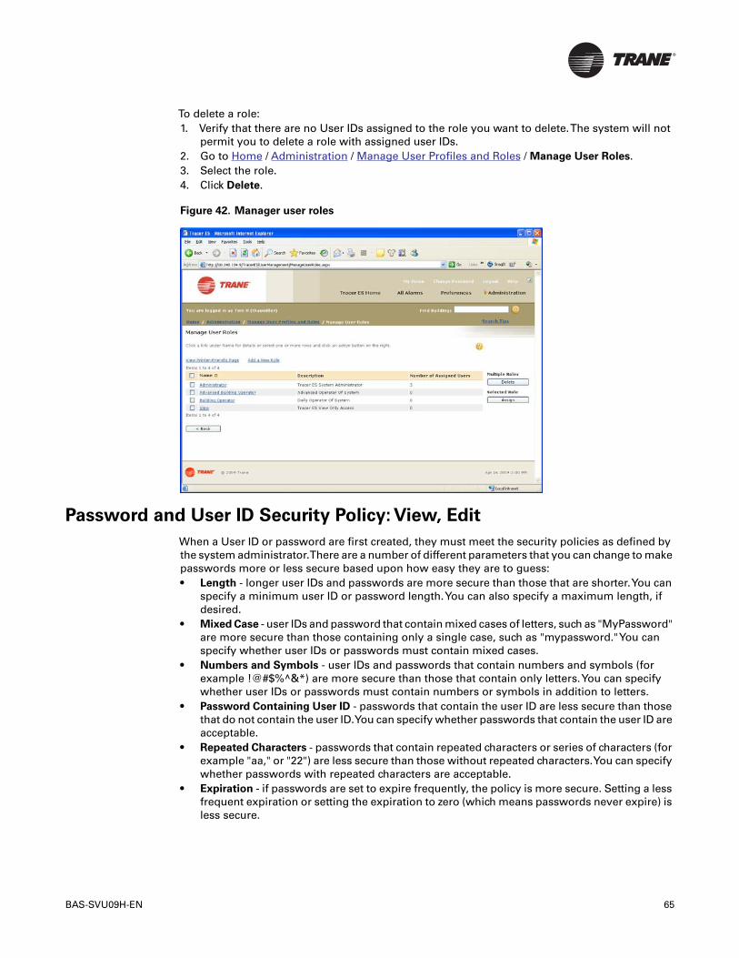
BAS-SVU09H-EN 65
To delete a role:1. Verify that there are no User IDs assigned to the role you want to delete.The system will not
permit you to delete a role with assigned user IDs.2. Go to Home / Administration / Manage User Profiles and Roles / Manage User Roles.3. Select the role.4. Click Delete.
Figure 42. Manager user roles
Password and User ID Security Policy: View, Edit
When a User ID or password are first created, they must meet the security policies as defined bythe system administrator.There are a number of different parameters that you can change to makepasswords more or less secure based upon how easy they are to guess:• Length - longer user IDs and passwords are more secure than those that are shorter.You can
specify a minimum user ID or password length.You can also specify a maximum length, ifdesired.
• Mixed Case - user IDs and password that contain mixed cases of letters, such as "MyPassword"are more secure than those containing only a single case, such as "mypassword."You canspecify whether user IDs or passwords must contain mixed cases.
• Numbers and Symbols - user IDs and passwords that contain numbers and symbols (forexample !@#$%^&*) are more secure than those that contain only letters.You can specifywhether user IDs or passwords must contain numbers or symbols in addition to letters.
• Password Containing User ID - passwords that contain the user ID are less secure than thosethat do not contain the user ID.You can specify whether passwords that contain the user ID areacceptable.
• Repeated Characters - passwords that contain repeated characters or series of characters (forexample "aa," or "22") are less secure than those without repeated characters.You can specifywhether passwords with repeated characters are acceptable.
• Expiration - if passwords are set to expire frequently, the policy is more secure. Setting a lessfrequent expiration or setting the expiration to zero (which means passwords never expire) isless secure.
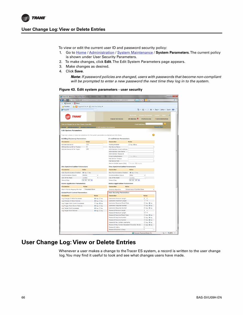
66 BAS-SVU09H-EN
User Change Log: View or Delete Entries
To view or edit the current user ID and password security policy:1. Go to Home / Administration / System Maintenance / System Parameters.The current policy
is shown under User Security Parameters.2. To make changes, click Edit.The Edit System Parameters page appears.3. Make changes as desired.4. Click Save.
Note: If password policies are changed, users with passwords that become non-compliantwill be prompted to enter a new password the next time they log in to the system.
Figure 43. Edit system parameters - user security
User Change Log: View or Delete Entries
Whenever a user makes a change to theTracer ES system, a record is written to the user changelog.You may find it useful to look and see what changes users have made.
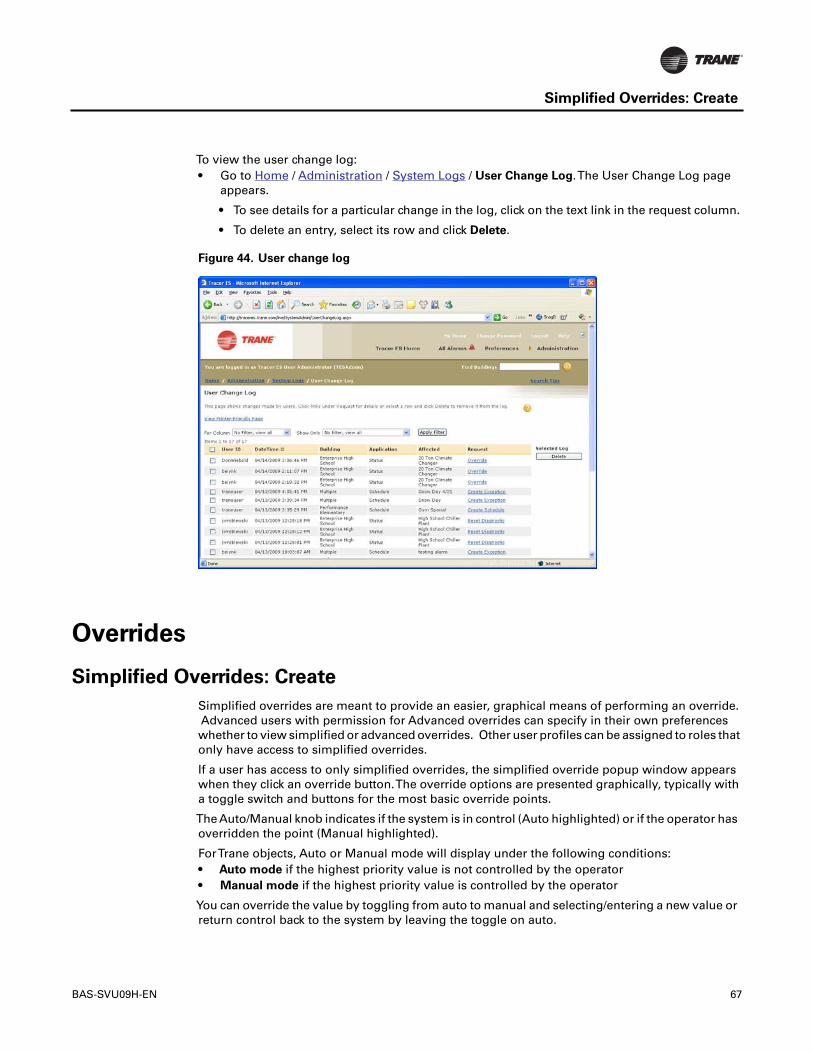
BAS-SVU09H-EN 67
Simplified Overrides: Create
To view the user change log:• Go to Home / Administration / System Logs / User Change Log.The User Change Log page
appears.
• To see details for a particular change in the log, click on the text link in the request column.
• To delete an entry, select its row and click Delete.
Figure 44. User change log
Overrides
Simplified Overrides: Create
Simplified overrides are meant to provide an easier, graphical means of performing an override.Advanced users with permission for Advanced overrides can specify in their own preferenceswhether to view simplified or advanced overrides. Other user profiles can be assigned to roles thatonly have access to simplified overrides.
If a user has access to only simplified overrides, the simplified override popup window appearswhen they click an override button.The override options are presented graphically, typically witha toggle switch and buttons for the most basic override points.
The Auto/Manual knob indicates if the system is in control (Auto highlighted) or if the operator hasoverridden the point (Manual highlighted).
ForTrane objects, Auto or Manual mode will display under the following conditions:• Auto mode if the highest priority value is not controlled by the operator• Manual mode if the highest priority value is controlled by the operator
You can override the value by toggling from auto to manual and selecting/entering a new value orreturn control back to the system by leaving the toggle on auto.

68 BAS-SVU09H-EN
For a non–Trane BACnet device Manual mode will always display, indicating that the point isoverridden (Change to state).
Note:The Auto/Manual control is disabled if the operator's default priority level is lowerthan the highest priority level shown in the Priority Array.
Users with advanced override capability according to their user role permissions can also click theAdvanced button, which opens the advanced override page.
Advance Overrides: View, Create, Release
There are four basic types of advanced override that can be performed if your user profile isassigned to a user role capable of performing advanced overrides:
PresentValue Override - circumvents the present value specified by the control strategy for a unitcontroller or application. The override value stays in effect until the value is released (by a user)and unless a competing request with a higher priority is received for the value.
Additional Override - lets you specify a value for a piece of equipment that has additional pointsthat can be individually overridden, such as valves. The only points available for this type ofoverride are those that appear on the Overrides tab of the Properties window inTracer Summit(namely, VAVType II/II/IV, Space Comfort Controller (v14 & earlier)/(v15 & later), Voyager RooftopUnit, Commercial Self-Contained Unit, Intellipack Rooftop Unit,Terminal Unit Controller).Additional overrides remain in effect until they are changed by another user.
Timed Override - if a BCU has been configured for an areaTimed Override,Tracer ES can be usedto make the timed override active or inactive. Details about the timed override can only be editedusingTracer Summit. Once activated, a timed override remains in effect until its configured timeexpires or a user deactivates it, whichever happens first.
Note: Additional overrides and timed overrides are considered "Advanced Overrides" interms of user role permissions. If your user profile is assigned to a role without access forAdvanced Overrides, the Additional Overrides section and theTimed Override button willnot appear on theTracer ES pages.
• Point Out of Service Override - Inputs and outputs can be put out of service with a specifiedvalue, and put back into service if they are currently out of service. In order to perform a pointservice type of override, your user profile must be assigned to a role with Point Servicepermission enabled.
Note: For detailed information about advanced override fields, see the sections that follow.
To create a present value override:1. Use the building navigation sidebar to go to the status page for the unit controller or application
you want to override.2. Click Override.3. Select Override Present Value.4. Select the priority level at which you want the override applied next to Apply at Priority Level.
You cannot select a higher priority than your user role permits. Look at the priority array to seethe competing controls for the present value.Your override will have no effect as long as thereis a competing request of higher priority.
5. Select the present value you want to apply next to Change ValueTo. Only valid values willappear in the list.
6. Click Apply.
To create an additional override.1. Use the building navigation sidebar to go to the status page for the unit controller or application
you want to override.2. Click Override.3. Locate the point you want to override, below the present value override.4. Select a new value in the Value column5. Click Apply.

BAS-SVU09H-EN 69
VAV II/II/IV: Advanced Overrides
To put an input or output point into or out of service:1. Use the building navigation sidebar to go to the status page for the input or output.2. Locate and select the point.3. Click Override.4. Select In service to put the point into service or select Out of Service to put the point out of
service. If you are putting an input point out of service, specify a value for the point to use whileit is out of service.
5. Click Apply.
To release a standard override:1. Use the building navigation sidebar to go to the status page for the unit controller, application,
or points that you want to override.2. Click Override.3. Click Release Control.4. Click Apply.
Figure 45. Override
To activate or deactivate a timed override for an area:1. Use the building navigation sidebar to go to the area status page of the area you want to
override.2. ClickTimed Override.TheTimed Override popup window appears.3. Select Active to activate the timed override or Inactive to deactivate the timed override.4. Click Apply.
VAV II/II/IV: Advanced Overrides
Note: Some of the descriptive information in this topic refers to elements that only appearon theTracer SUMMIT user interface.
When you go to the advanced overrides page for aVAV II/III or IV type UCM, in addition to PresentValue, the following fields can be overridden:

70 BAS-SVU09H-EN
VAV II/II/IV: Advanced Overrides
Calibrate Valve
Sends an air valve calibration request to the VAV.This request can be done manually or byreferencer.
If calibration is manually initiated, theVAV does not recognize the calibration request until this fieldtransitions from Normal to Recalibrate, then stays for at least one minute in Recalibrate beforegoing back to Normal again. If the switch is delayed in being set back to Normal, or if it is left in therecalibrate state indefinitely, the VAV does not calibrate. Additionally, the flow overrides do notfunction properly.
When a VAV undergoes calibration, it initializes the zero value for the pressure transducer (flowring) measurements, re-establishes the air valve position, and re-establishes the water valveposition if applicable.To re-establish valve position, the VAV over-drives the valve closed for 30seconds beyond the configured stroke time (water valve for stroke time plus 15 seconds).
A VAV automatically recalibrates after power up or after 15 minutes of communication loss.
Because the unit valve closes during a calibration, calibrating all of the units at the same time couldresult in high duct pressure.To prevent this problem, the VAVs calibrate at different times from acommon calibration start time. In any given group ofVAVs, only 25% percent of them are allowedto calibrate at the same time.
Example: Once the calibration flag is set (at time = 0 minutes), the first 25% of a group ofVAVs begins the calibration process. Seven minutes later (at time = 7 minutes) the second25% of the group begins calibration. Seven minutes later (at time = 14 minutes) the third 25%of the group begins calibration. Finally, seven minutes later (at time = 21 minutes) the fourth25% of the group begins calibration. Depending upon the air valve drive time, the entirecalibration process for the group of VAVs could take up to 33 minutes to complete.
The membership of a VAV ll/lll UCM to a calibration group is predetermined.The ICS address ofthe UCM determines which group the UCM falls into.The list below shows the entire range ofVAVUCM ICS addresses divided into four calibration groups.• 1st Group: 68, 72, 76, 80, 84, 88, 92, 96, 100, 104, 108, 112, 116, 120, 124, 128.• 2nd Group: 65, 69, 73, 77, 81, 85, 89, 93, 97, 101, 105, 109, 113, 117, 121, 125.• 3rd Group: 66, 70, 74, 78, 82, 86, 90, 94, 98, 102, 106, 110, 114, 118, 122, 126.• 4th Group: 67, 71, 75, 79, 83, 87, 91, 95, 99, 103, 107, 111, 115, 119, 123, 127.
VAV UCMs can have drive times up to 666 seconds (11.1 minutes). Since UCM resets are staggeredby 7 minutes, up to half of the units could potentially be closed at one time during the calibrationprocess.
After a power failure, the calibration start time is delayed until twenty minutes after power isrestored. If a recalibrate command has been downloaded fromTracer Summit, the calibrationbegins immediately according to the address schedule as described above.
Drive Open
Sends a flow override to the UCM that causes the UCM to drive its damper fully open, turn off allunit heat, and disable its parallel fan.
Flow override selections that are not possible due to the priority scheme are unavailable. Also, ifmultiple flow overrides exist simultaneously, the following priority scheme applies: DRIVE OPEN,DRIVE CLOSED, DRIVE MINIMUM, DRIVE MAXIMUM, AUTO. Both VAS and the VAV editor canprovide flow overrides.The VAV editor flow overrides are higher priority.
Drive Closed
Sends a flow override to the UCM.This causes the UCM to drive its damper fully closed, turn theunit fan off, and turn the unit heat off.

BAS-SVU09H-EN 71
VAV II/II/IV: Advanced Overrides
Flow override selections that are not possible due to the priority scheme are unavailable. Also, ifmultiple flow overrides exist simultaneously, the following priority scheme applies: Drive Open,Drive Closed, Drive Minimum, Drive Maximum, Auto. Both VAS and the VAV editor can provideflow overrides.The VAV editor flow overrides are higher priority.
Example: If an operator has selected Drive Closed override, the Drive Min and Drive Maxoverride fields are not available because they cannot affect the UCM.The Drive Openoverride field is still available for use because it can still affect the UCM.
Drive Min
Sends a flow override to the UCM that causes the UCM to drive its damper to its Active Min FlowSetpoint.The Active Min Flow Setpoint is one of the following:• Min Cooling flow setpoint• Min Heating flow setpoint• Min Local Heating flow setpoint• Series F PD (pressure dependent) Mode Min Damper Pos flow setpoint (which does not appear
in the VAV editor and applies to only VariTrane F boxes.)
Note:The Active Min Flow Setpoint may not match what appears in the VAV editor if theSetpoint Multiplier is enabled and the Multiplier Value is not equal to one.
Flow override selections that are not possible due to the priority scheme are unavailable (grayed).Also, if multiple flow overrides exist simultaneously, the following priority scheme applies: DRIVEOPEN, DRIVE CLOSED, DRIVE MINIMUM, DRIVE MAXIMUM, AUTO. Both VAS and the VAV editorcan provide flow overrides.The VAV editor flow overrides are higher priority.
Example: If an operator has selected the Drive Min override, the Drive Max override fieldis not available because it is the only override that cannot affect the UCM.
Drive Max
Sends a flow override to the UCM.This causes the UCM to drive its damper to the Max flowsetpoint. Electric Heat and Parallel fans are disabled during a max flow override.
Flow override selections that are not possible due to the priority scheme are unavailable (grayed).Also, if multiple flow overrides exist simultaneously, the following priority scheme applies: DriveOpen, Drive Closed, Drive Minimum, Drive Maximum, Auto. Both VAS and the VAV editor canprovide flow overrides.The VAV editor flow overrides are higher priority.
Automatically, the VAS includes a capability to override its VAV members to maximum if the VASis in the heat mode and the following check box is selected: Drive VAVs to Max Flow if VAS isHeating.
Example: If an operator has selected Drive Max override, the Drive Min, Drive Closed, andDrive Open override fields are still available for use because they can still affect the UCM.
Parallel Fan Control
This field is available for units equipped with a parallel fan.
Use this field to disable the operation of the parallel fan. When a unit's parallel fan is locked out,the UCM does not use its fan or its local electric heat (Staged Electric, Electric Fast Pulse, ElectricSlow Pulse).
Terminal Heat
Shows the state of the terminal heat override.When it is set to Reheat Lockout (either manually orby referencer), the UCM is not allowed to use its terminal heat.
Drive Open Hot Water Outputs/Valve
Note:This field is only available when the unit has Staged Hot Water or Proportional HotWater heat types.

72 BAS-SVU09H-EN
Forces the UCM to turn on all of its hot water outputs or drive open its proportional hot water valve.This may be useful for water system balancing.The UCM maintains the full open condition overpower failures. Unit heat must be enabled in order for this condition to be effective.To cancel thefull open condition, click to clear the Drive Open Hot Water Outputs/Valve check box.
Only units with the following heat types are affected:• Staged Hot Water: All three of the heat outputs are energized. If the unit has a fan, Output 3
is not affected.• Proportional Hot Water:The hot water valve connected to Outputs 1 and 2 is driven open.
Control Offset
When Setpoint Not Offset is selected, the control offset is not used and the heating and coolingsetpoints are not affected. Selecting Setpoint Offset means that control offset is used and theheating and cooling setpoints are offset (added to the cooling setpoint and subtracted from theheating setpoint) by the Control Offset Value.
A referenced binary property in the zero state is interpreted as Setpoint Not Offset, and a referencedbinary property in the one state is interpreted as Setpoint Offset.
In UCM software versions 1.0–3.0, the thumbwheel setpoint is not effected if selected as thesetpoint source. In version 3.1 and later versions, the setpoint offset is applied to the thumbwheelsetpoints.
Regardless of the Control Offset field setting, if the present value of the VAV is demand limit, theVAV applies the control offset value to its heating and cooling setpoint.
Control Offset Value
If theVAV has been directed to apply a control offset to its heating and cooling setpoints, the valueappearing in the Control Offset Value is the offset applied.
The Control Offset Value is added to the occupied cooling setpoint and subtracted from theoccupied heating setpoint to determine the occupied mode active setpoints.
Minimum Flow Setpoint Multiplier
Select the control source to enable or disable the Minimum Flow Setpoint Multiplier feature thatadjusts the UCM minimum flow setpoint.
If Auto is selected, either manually or by referencer, a multiplier value of 1.0 is sent to the UCM.
If a referenced value is selected, the property must be Enabled to send the edited or referencedmultiplier value.
Field set to Auto
• In the occupied mode, the UCM’s control algorithm internally sets the multiplier value to 1.0,which in effect does not change the minimum cooling flow setpoint.
• In the unoccupied mode, the UCM releases the minimum flow setpoint to zero.
Field set to Enabled
• During the occupied mode, the UCM uses the value in the MultiplierValue field to adjust activeminimum flow setpoint.
• During the unoccupied mode, the UCM uses the value in the MultiplierValue field to adjust theactive minimum flow setpoint if the multiplier value is greater then 1.0. If the multiplier valueis less than or equal to 1.0, the UCM releases the minimum flow setpoint to zero.
Example:The Min Cooling flow setpoint = 1000 CFM (472 L/s).The Multiplier Value = 0.5.With the Minimum Flow Setpoint Multiplier field Enabled, the active minimum cooling flowsetpoint would be 0.5 x 1000 CFM (472 L/s) = 500 CFM (236 L/s), assuming for this examplethat the active minimum flow setpoint is the Min Cooling flow setpoint.
Multiplier Value
The edited cooling minimum flow/position can be adjusted by applying this multiplier.

BAS-SVU09H-EN 73
Space Comfort Controller (v14 & earlier): Advanced Overrides
In the heating mode, the heating minimum overrides the "adjusted" cooling minimum if it is higher.If the adjusted cooling minimum is higher than the heating minimum and the UCM is in heatingmode, the adjusted cooling minimum applies.
If the multiplier = 1.0, the heating minimum always applies while in the heating mode. If themultiplier = 0, the cooling minimum = 0.
Example:The Min Cooling flow setpoint = 1000 CFM (472 L/s).The Multiplier Value = 0.5.With the Minimum Flow Setpoint Multiplier field Enabled, the active minimum cooling flowsetpoint would be 0.5 x 1000 CFM (472 L/s) = 500 CFM (236 L/s), assuming for this examplethat the active minimum flow setpoint is the Min Cooling flow setpoint.
Space Comfort Controller (v14 & earlier): Advanced Overrides
Note: Some of the descriptive information in this topic refers to elements that only appearon theTracer SUMMIT user interface.
When you go to the advanced overrides page for a Space Comfort Controller, in addition to PresentValue, the following fields can be overridden:
Water Valve
This group is hidden when connected to the LCI-R controller and LCI-I controller.
Drive Open
Select Auto or Open or set a referencer to determine the setting.When set to Open, the unit drivesall of its hydronic valves to 100 percent open. For example, you might set the valves to open whenbalancing the system.
Note:The Drive Open override takes precedence over Drive Closed. When the Drive Openfield is set to Open, the Drive Closed field becomes unavailable.
Drive Closed
Select Auto or Closed or set a referencer to determine the setting. When set to Closed, the unitdrives all of its hydronic valves to 100 percent closed.
Air Valve
This group appears when the unit is read to be a VAV UCM. It also appears when you opt toconfigure the controller as a VAV.
Drive Open
Select Auto or Open or set a referencer to determine the setting. When set to Open, the VAV airvalve is 100 percent open. For example, during a smoke purge, theVAV box needs to be 100 percentopen.
Note:This field is available only if the unit is configured to be a VAV and is online or whenyou change the unit type to VAV while the unit is offline.
Drive Closed
Select Auto or Closed or set a referencer to determine the setting.When set to Closed, theVAV airvalve is 100 percent closed.
Note:This field is available only if the unit is configured to be a VAV and is online or whenyou change the unit type to VAV while the unit is offline.
74 BAS-SVU09H-EN
Drive Min
Select Auto or Minimum or set a referencer to determine the setting. When set to Minimum, theVAV air valve opens to its configured minimum setpoint. For example, during certain outside airconditions, you may want the VAV boxes to stay at their minimum position.
Note:This field is available only if the unit is configured to be a VAV and is online or whenyou change the unit type on the controller to a VAV while the unit is offline.
Drive Max
Select Auto or Maximum or set a referencer to determine the setting. When set to Maximum, theVAV air valve opens to its configured maximum setpoint.
Note:This field is available only if the unit is configured to be a VAV and is online or whenyou change the unit type on the Status tab to a VAV while the unit is offline.
Space Comfort Controller (v15 & later): Advanced Overrides
Note: Some of the descriptive information in this topic refers to elements that only appearon theTracer SUMMIT user interface.
When you go to the advanced overrides page for a Space Comfort Controller, in addition to PresentValue, the following fields can be overridden:
Water Valve
This group is hidden when connected to the LCI-R controller and LCI-I controller.
Drive Open
Drives all of the hydronic valves to 100% open.This option is unavailable if the UCM or BCU isoffline.
Drive Closed
Drives all of the hydronic valves to 100% closed.This option is unavailable if the UCM or BCU isoffline.
Release Override
Returns the device back to normal hydronic valve operation.
Air Valve
This group appears when the unit is read to be a VAV UCM. It also appears when you opt toconfigure the controller as a VAV.
Drive Open
Select Auto or Open or set a referencer to determine the setting. When set to Open, the VAV airvalve is 100 percent open. For example, during a smoke purge, theVAV box needs to be 100 percentopen.
Note:This field is available only if the unit is configured to be a VAV and is online or whenyou change the unit type to VAV while the unit is offline.
Drive Closed
Select Auto or Closed or set a referencer to determine the setting.When set to Closed, theVAV airvalve is 100 percent closed.
Note:This field is available only if the unit is configured to be a VAV and is online or whenyou change the unit type to VAV while the unit is offline.
Drive to Min Cooling Flow Setpoint
The unit drives all valves to the minimum setpoint.This option is unavailable if the UCM or BCUis offline.

BAS-SVU09H-EN 75
Voyager Rooftop Unit: Advanced Overrides
Drive Max Cooling Flow Setpoint
The unit drives all valves to the maximum setpoint.This option is unavailable if the UCM or BCUis offline.
Auto Commissioning Sequence Group
This group only displays when the UCM is read to be aTrane VAV, or you opt to configure thecontroller as a VAV.
Start (Auto Commissioning) Sequence
Use this option to command aTraneVAV box to start its autocommissioning sequence. Full use ofthis function requires the presence of an auxiliary temperature sensor in the discharge air stream(without it the fan and reheat operation cannot be tested).TheTrane VAV box reports a status of"Test" in the Active Mode field on the Status tab while the sequence is executing.
The Autocommissioning Sequence may take up to 20 minutes depending on the local reheatcapability and assuming a 90 second air damper stroke time on the VAV box.
Cancel (Auto Commissioning) Sequence
Use this option to command aTrane VAV box to stop its autocommissioning sequence.TheTraneVAV box reports a status of "Test" in the Active Mode field on the Status tab while the sequence isexecuting.
Note: If the autocommissioning sequence is canceled while the VAV box is calibrating theVAV box first finishes its calibration before returning to normal operation.
Voyager Rooftop Unit: Advanced Overrides
Note: Some of the descriptive information in this topic refers to elements that only appearon theTracer SUMMIT user interface.
When you go to the advanced overrides page for a Voyager Rooftop Unit in addition to PresentValue, the following fields can be overridden:
Compressor Control
In this field you can lock out all compressors on theVoyager. By locking out the compressors, a non-heat pump Voyager will not be able to provide any mechanical cooling. If the compressors arelocked out on a heat pump unit, theVoyager will not be able to provide cooling or heating from thecompressors. Even though theVoyager compressor does not require an external ambient lockout,you could use this field to lockout the compressors when the outdoor air temperature falls belowa certain value.• Disable - Stop mechanical cooling on the Voyager from operating.• Auto (default) - Enable mechanical cooling to be operational when requested by theVoyagers
cooling control algorithms.• Referencer - Reference either a binary system value or a CPL Saved value to decide whether
or not to lock out the compressors. A referenced property in the 0 state will be interpreted asDisable. When the property is 1, the state will be Auto.
Note:This field has no effect on the economizer control; only compressor cooling isaffected.
76 BAS-SVU09H-EN
Voyager Rooftop Unit: Advanced Overrides
Cooling Stages Enabled
This field allows you to limit the number of stages of mechanical cooling that will be allowed tooperate in theVoyager.This field may be used in a demand-limiting control strategy that limits thestages of compressors operating during periods of high electrical demand.• Constant - Enter a value to select the number of cooling stages enabled.To allow all stages
of cooling to operate normally in theVoyager, enter 3. Enter 0 to inhibit all stages of mechanicalcooling.
• Referencer -You can reference an analog system value that determines the number of coolingstages to be enabled (0 - 3).
Note:This field does not affect compressor operation during the heat mode for heat pumpunits.
Pressurization Mode
This applies only to 27 ½ to 50 tonVoyagers. If communications to theVoyager are down, this fieldis still available for editing.
The field allows you to activate the Pressurization Mode on the Voyager unit.The PressurizationMode introduces as much outdoor air as possible to the conditioned space without providing ameans for exhausting air, which can result in a positive static pressure condition in the space.
During the Pressurization Mode, the supply fan is turned on, inlet guide vanes (orVFD) are drivenopen, the exhaust fan is turned off, the outside air damper is driven open, and all heating andcooling is disabled.
If multiple ventilation override modes are activated simultaneously, the pressurization mode hasthe highest priority and the purge mode has the lowest priority.
The ventilation override modes can be used in situations requiring the Voyager rooftop units toassist in coordinated air movement control across several zones or floors.• Auto - Allow the unit to operate normally.• On - Activate the Pressurization Mode on the unit.• Referencer - Reference a binary system value that decides when to activate the pressurization
mode.The referenced property in the 0 state puts the Pressurization mode to Auto, and a 1value is interpreted as On.
Exhaust Mode
This applies only to 27 ½ to 50 tonVoyagers. If communications to theVoyager are down, you canstill edit in this field.
This field allows you to activate the exhaust mode on theVoyager unit.The Exhaust Mode is usedto discharge existing air from the conditioned space without providing a means for replacementair, which can result in a negative static pressure condition in the space.
During the Exhaust Mode, the supply fan is turned off, the inlet guide vanes (or VFD) are closed,the exhaust fan is turned on (if the unit is equipped with an exhaust fan), the outside air damperis closed, and all heating and cooling is disabled.
If multiple ventilation override modes are activated simultaneously, the pressurization mode hasthe highest priority and the purge mode has the lowest priority.
Ventilation override modes can be used in situations requiring the rooftop units to assist incoordinated air movement control across several zones or floors.• Auto (default) - Allow the Voyager to operate normally.• On - Activate the Exhaust Mode on the Voyager unit.• Referencer - Reference a binary system value that decides when to activate the exhaust
mode. If the referenced value is 1, Auto is used. If the value is 0, the Exhaust Mode is On.

BAS-SVU09H-EN 77
Voyager Rooftop Unit: Advanced Overrides
Purge Mode
This field allows you to activate the Purge Mode on theVoyager unit.The Purge Mode is most oftenused to “change” the air in the conditioned space in an effort to improve the indoor air quality.
During the purge mode the supply fan is turned on, the inlet guide vanes (or VFD) if installed,control to the static pressure setpoint, the exhaust fan is controlled normally, the outside airdamper is driven open, and all cooling is disabled.The unit’s heating capacity remains enabledduring the Purge Mode. If multiple ventilation override modes are activated simultaneously, thepressurization mode has the highest priority and the Purge Mode has the lowest priority.
Ventilation override modes can be used in situations requiring the rooftop units to assist incoordinated air movement control across several zones or floors.• Auto (default) - Operat the unit normally.• On - Activate Purge Mode on the unit.• Referencer - Reference a binary system value that decides when to activate the Purge Mode.
When the referenced property is 0 it is interpreted as Auto. For a referenced property in the 1state, the Purge Mode will be On.
Outside Air Dampers
Use this field to override control of the economizer damper and drive the damper to the fully closedposition.This field might be used to drive the economizer closed during times of extremely pooroutdoor air quality to prevent the conditioned space from receiving the bad air.• Auto (default) - Control the damper normally.• Drive Closed - Drive the outside air damper to the fully closed position and keep it in that
position until this field is set to Auto.• Referencer - Reference a binary system value that will decide when to drive the economizer
damper fully closed. A referenced property in the 1 state will be interpreted as Close and aproperty in the 0 state will put the Outside Air Dampers to Auto.
Heating Control
This field allows you to disable all heating capacity on the Voyager.• Auto (default) - Permit the unit to heat when requested by its heating control algorithms.• Disable - Do not permit the unit to heat.• Referencer - Reference a binary system value that decides whether or not to lock out the
heating. A property in the 0 state will be interpreted as Disable, and a 1 state will be interpretedas Auto.
Enable Emergency Heat Mode
In the emergency heat mode, the unit locks out compressors and only uses auxiliary electric heatto maintain the conditioned space at the zone heating setpoint.
This field will only be available if the unit is a heat pump option, and the Heat/Cool Control Sourceis set toTracer.
Disable Auxiliary Heat
Note:This field is available only when the unit is a heat pump.
Prevent the electric heat strips from operating.
ServiceTest Group
If the Voyager rooftop is not communicating with the BCU when the Overrides screen is opened,the ServiceTest field group will be unavailable.

78 BAS-SVU09H-EN
Commercial Self-Contained Unit: Advanced Overrides
Test Mode
You can place theVoyager into the service test mode by choosing a test mode in this box. Use theservice test mode during job startup and commissioning, and as a tool for diagnosing unitproblems.When you select a service test mode, all standard unit operations cease and theVoyageris placed into the selected test mode.
Because the service test mode is not intended for use over extended periods of time, there is a timerthat will disable the service test mode after 15 minutes. Each time you change the test mode, the15-minute timer resets.
TheTest Modes that are available will be specific to the type ofVoyager unit that is connected: heatpump, 3 - 25 ton constant volume, 27.5 – 50 constant volume, or VAV units.
Status
This field displays the test mode status. Status information is automatically refreshed every 10seconds. When the Voyager is not in a service test mode, this message displays: “No test inprogress.”
Start
Initiate a service test.
Stop
Cancel a service test.
Commercial Self-Contained Unit: Advanced Overrides
Note: Some of the descriptive information in this topic refers to elements that only appearon theTracer SUMMIT user interface.
When you go to the advanced overrides page for a Commercial Self-Contained Unit in addition toPresent Value, the following fields can be overridden:
Mechanical Cooling Control
Use this referencer edit control to lock out all mechanical cooling at the unit. When this control isset to Disable, the operations of the unit’s compressors are stopped.When the control is set toAuto,the unit operates normally.
Heating Control
Use this referencer edit control to override the current operating mode of the UCM. When thiscontrol is set to Disable, the unit is prevented from actively heating.When the control is set toAuto,the unit operates normally.
Ventilation Control
Use this referencer edit control to override the ventilation output of the UCM.When this control isset to Auto, the CSC is allowed to decide when to turn its ventilation output on. When the controlis set to Disable, the CSC unit is forced to turn off its ventilation output.
Maximum Ventilation Control
Use this referencer edit control to override the maximum ventilation mode of the CSC unit.Whenthis control is set to Auto, the CSC operates normally. When the control is set to Forced, the CSCis put in Forced Max Vent mode. In this mode, all mechanical heating and cooling is off, and thesupply fan is on. Static pressure control is also active in the Forced Max Vent mode.

BAS-SVU09H-EN 79
Intellipack Rooftop Unit: Advanced Overrides
Intellipack Rooftop Unit: Advanced Overrides
Note: Some of the descriptive information in this topic refers to elements that only appearon theTracer SUMMIT user interface.
When you go to the advanced overrides page for a Intellipack Rooftop Unit in addition to PresentValue, the following fields can be overridden:
Heating Control
Use this referencer edit control to disable all the heating on the IntelliPak.When this control is setto Disable, the unit is prevented from actively heating. When the control is set to Auto, the unitoperates normally.
A system binary property can be referenced to control this field to Disable or Auto. If the referenceris in the Off state, Disable will appear in the field. If the referencer is in the On state,Auto will appearin the field.
Cooling Control
Use this referencer edit control to disable all cooling (DX and ChilledWater) on the IntelliPak.Whenthis control is set to Disable, cooling on the IntelliPak will not be allowed to operate. When thiscontrol is set to Auto mechanical cooling at the IntelliPak will be functional and will cool whenrequested by the IntelliPak’s cooling control algorithms.
A system binary property can be referenced to control this field to Disable or Auto. If the referenceris in the Off state, Disable will appear in the field. If the referencer is in the On state,Auto will appearin the field.
Ventilation Overrides
Use these referencer edit controls to initiate aTracer Summit Ventilation Override.These are fivemodes of ventilation override (A, B, C, D and E) thatTracer Summit can initiate. A referencer editcontrol exists for each one of these modes.The specifics of how the IntelliPak will function for eachoverride is handled at the IntelliPak's human interface panel. If Auto is selected,Tracer Summit isnot requesting a VOM (The VOM modes can still be activated locally at the IntelliPak UCM). If Onis selected,Tracer Summit is requesting a VOM to be activated.
A system binary property can be referenced to control this field to On or Off.The On state generatesthe On value.The Off state generates the Auto value.
Terminal Unit Controller: Advanced Overrides
Note: Some of the descriptive information in this topic refers to elements that only appearon theTracer SUMMIT user interface.
When you go to the advanced overrides page for aTerminal Unit Controller in addition to PresentValue, the following fields can be overridden:

80 BAS-SVU09H-EN
Terminal Unit Controller: Advanced Overrides
Valve 1 - Closed
When theTUC is programmed to useTracer as the Unit Control Source, the Valve 1 – Closed fieldmay be used to override control of Valve 1 to close it.This field is available only forTUCconfigurations that have Valve 1 configured (For example, 2 Pipe Heat or Cool Valve, 2 Pipe CoolValve, 2 Pipe Heat Valve, SCUV, DX Cool, 2 Pipe hydro heat or 4 Pipe Heat and Cool Valve).Toconfigure the valve requires selecting Valve 1 as a Change UnitType parameter during offlineediting. (The Change UnitType button is located on the Status tab.)• Auto (default) -TUC Valve 1 is issued an automatic mode by the building controls system
(Tracer Summit).TheTUC uses its own Valve 1 algorithms to control the exhaust fan’soperation.
• Closed -TUC Valve 1 is issued a Closed mode command by the building control system.• Referencer - Select this to make the function dependent on the current value of another binary
property in the system. When the referenced property is in the Off state, the Valve 1 will beallowed to run in the Auto mode. If the referenced property is in the On state, the Valve 1 willbe commanded to a Closed position.
Note: If both Open and Closed modes are overridden simultaneously, an Open modecommand takes priority over the Closed mode (as decided by theTUC).
Valve 1 - Open
When theTUC is programmed to useTracer as the Unit Control Source, theValve 1 – Opened fieldmay be used to override control of Valve 1, in order to open it.This field is available only forTUCconfigurations that haveValve 1 (example "2 Pipe Heat or CoolValve" or "2 Pipe CoolValve", "2 PipeHeatValve", "SCUV, DX Cool, 2 Pipe hydro heat" or "4 Pipe Heat and CoolValve").This configurationrequires selecting Valve 1, during offline editing.This does not apply for units which have a Faceand Bypass damper.• Auto (default) -TUC Valve 1 is issued an automatic mode by the building control system
(Tracer Summit).TheTUC uses its own Valve 1 algorithms to control the exhaust fan’soperation.
• Open -TUC Valve 1 is issued an Open mode command by the building control system.• Referencer - Select this to make the function dependent on the current value of another binary
property in the system. When the referenced property is in the Off state, the Valve 1 will beallowed to run in the Auto mode. If the referenced property is in the On state, the Valve 1 willbe commanded to an Open position.
Note: If both Open and Closed modes are overridden simultaneously, an Open modecommands takes priority over the Closed mode (as decided by theTUC).

BAS-SVU09H-EN 81
Terminal Unit Controller: Advanced Overrides
Valve 1 - Face and Bypass Closed
When theTUC is programmed to useTracer as the Unit Control Source, the Valve 1 – Closed fieldmay be used to override control of bothValve 1 and the Face and Bypass damper, in order to closethem.This field is available only forTUC configurations that haveValve 1 configured (For example,2 Pipe Heat or Cool Valve, 2 Pipe Cool Valve, 2 Pipe Heat Valve, SCUV, DX Cool, 2 Pipe hydro heator 4 Pipe Heat and Cool Valve).This configuration requires selecting the Face and Bypass damperunit as a Change UnitType parameter, during offline editing.• Auto (default) -TheTUC’sValve 1 is issued an automatic mode by the building control system
(Tracer Summit).TheTUC uses its own algorithms to control Valve 1 and the Face and Bypassdamper operations.
• Closed -TheTUC’s Valve 1 and the Face and Bypass damper are issued a Closed modecommand by the building control system.
• Referencer - Select this to make the function dependent on the current value of another binaryproperty in the system. When the referenced property is in the Off state, the Valve 1 and theFace and Bypass damper will be allowed to run in the Auto mode. If the referenced propertyis in the On state, theValve 1 and the Face and Bypass damper will be commanded to a Closedposition.
Note: If both Open and Closed modes are overridden simultaneously, an Open modecommands takes priority over the Closed mode (as decided by theTUC).
Valve 1 - Face and Bypass Open
When theTUC is programmed to useTracer as the Unit Control Source, theValve 1 – Opened fieldmay be used to override the control of both Valve 1 and the Face and Bypass damper, in order toOpen them.This field is available only forTUC configurations that have a Face and Bypass damper.This configuration requires selecting the Face and Bypass damper unit as a Change UnitTypeparameter, during offline editing.• Auto (default) -TheTUC’sValve 1 is issued an automatic mode by the building control system
(Tracer Summit).TheTUC uses its own algorithms to control the Valve 1 and the Face andBypass damper operations.
• Open -TheTUC’sValve 1 and the Face and Bypass are issued an Open mode command by thebuilding control system.
• Referencer - Select this to make the function dependent on the current value of another binaryproperty in the system. When the referenced property is in the Off state, the Valve 1 and theFace and Bypass damper will be allowed to run in the Auto mode. If the referenced propertyis in the On state, theValve 1 and the Face and Bypass damper will be commanded to an Openposition.
Note: If both Open and Closed modes are overridden simultaneously, an Open modecommands takes priority over the Closed mode (as decided by theTUC).

82 BAS-SVU09H-EN
Terminal Unit Controller: Advanced Overrides
Valve 2 - Closed
When theTUC is programmed to useTracer as the Unit Control Source, the Valve 2 – Closed fieldmay be used to override control of Valve 2, in order to close it.This field is available only forTUCconfigurations that have Valve 2 configured.This configuration requires selecting 4 Pipe heat andCool Valve as a Change UnitType parameter, during offline editing.This does not apply for unitswhich have a Face and Bypass damper.• Auto (default) -TheTUC’s Valve 2 is issued an automatic mode command by the building
control system (Tracer Summit).TheTUC uses its own algorithms to control the Valve 2operation.
• Closed -TheTUC’sValve 2 is issued a Closed mode command by the building control system.• Referencer - Select this to make the function dependent on the current value of another binary
property in the system. When the referenced property is in the Off state, the Valve 1 will beallowed to run in the Auto mode. If the referenced property is in the On state, the Valve 2 willbe commanded to a Closed position.
Note: If both Open and Closed modes are overridden simultaneously, an Open modecommand takes priority over the Closed mode (as decided by theTUC).
Valve 2 - Open
When theTUC is programmed to useTracer as the Unit Control Source, this referencer edit maybe used to override the control of Valve 2, in order to open it.This field is available only forTUCconfigurations that have Valve 2 configured.This does not apply for units that have a Face andBypass damper.This configuration requires selecting 4 Pipe Heat and CoolValve as a Change UnitType parameter, during offline editing.• Auto (default) -TheTUC’sValve 2 is issued an automatic mode by the building control system
(Tracer Summit).TheTUC uses its own algorithms to control the Valve 2 operation.• Open -TheTUC’s Valve 2 is issued an Open mode command by the building control system.• Referencer - Select this to make the function dependent on the current value of another binary
property in the system.When the referenced property is in the Off state,Valve 1 will be allowedto run in theAuto mode. If the referenced property is in the On state,Valve 2 will be commandedto an Open position.
Note: If both Open and Closed modes are overridden simultaneously, an Open modecommand takes priority over the Closed mode (as decided by theTUC).
Valve 2 - Face and Bypass Closed
When theTUC is programmed to useTracer as the Unit Control Source, Valve 2 may be used tooverride the control of both Valve 2 and the Face and Bypass damper, in order to close them.Thisfield is available only forTUC configurations that have both Valve 2 and the Face and Bypassdamper.This configuration requires selecting both 4 Pipe Face and Bypass Damper unit as aChange UnitType parameter during offline editing.• Auto (default) -TheTUC’s Valve 2 and the Face and Bypass damper is issued an automatic
mode by the building control system (Tracer Summit).TheTUC uses its own algorithms tocontrol the Valve 2 and the Face and Bypass damper operations.
• Closed -TheTUC’s Valve 2 and the Face and Bypass damper are issued a Closed modecommand by the building control system.
• Referencer - Select this to make the function dependent on the current value of another binaryproperty in the system. When the referenced property is in the Off state, Valve 2 and the Faceand Bypass damper will be allowed to run in the Auto mode. If the referenced property is inthe On state, the Valve 2 and the Face and Bypass damper will be command to a Closedposition.
Note: If both Open and Closed modes are overridden simultaneously, an Open modecommand takes priority over the Closed mode (as decided by theTUC).

BAS-SVU09H-EN 83
Terminal Unit Controller: Advanced Overrides
Valve 2 - Face and Bypass Open
When theTUC is programmed to useTracer as the Unit Control Source, Valve 2 may be used tooverride the control of both Valve 2 and the Face and Bypass damper, in order to open them.Thisfield is available only forTUC configurations that have aValve 2 and the Face and Bypass damper.This configuration requires selecting 4 Pipe Face and Bypass Damper unit as a Change UnitTypeparameter, during offline editing.• Auto (default) -TheTUC’s Valve 2 and the Face and Bypass damper is issued an automatic
mode by the building control system (Tracer Summit).TheTUC uses its own algorithms tocontrol the Valve 2 and the Face and Bypass damper operations.
• Open -TheTUC’s Valve 2 and the Face and Bypass damper are issued an Open modecommand by the building control system.
• Referencer - Select this to make the function dependent on the current value of another binaryproperty in the system. When the referenced property is in the Off state, the Valve 2 and theFace and Bypass damper will be allowed to run in the Auto mode. If the referenced propertyis in the On state, the Valve 2 and the Face and Bypass damper will be command to an openposition.
Note: If both Open and Closed modes are overridden simultaneously, an Open modecommands takes priority over the Closed mode (as decided by theTUC).
Outdoor Air Damper - Closed
When theTUC is programmed to useTracer as the Unit Control Source and is equipped with anoutdoor air damper, the Outdoor Air Damper - Closed field is used to override the control of theoutdoor air damper, in order to closed it.This configuration requires selecting Outdoor Air Damperas a Change UnitType parameter during offline editing. (The Change UnitType button is locatedon the Status tab.)
• Auto (default) -The building control system (Tracer Summit) controls theTUC to use its ownOutdoor Air Damper algorithms to control the outdoor air damper’s operation.
• Closed -The building control system (Tracer Summit) controls theTUC’s outdoor air damper’soperation.The outdoor air damper is commanded to a closed position.
• Referencer - Select this option to make the function dependent on the current value of anotherbinary property in the system.When the referenced property is in the Off state, the outdoor airdamper will be allowed to run in the Auto mode. If the referenced property is in the On state,the outdoor air damper will be commanded to Closed.
Note: If both Open and Closed modes are overridden simultaneously, an Open modecommands takes priority over the Closed mode (as decided by theTUC).

84 BAS-SVU09H-EN
Terminal Unit Controller: Advanced Overrides
Outdoor Air Damper - Open
When theTUC is programmed to useTracer as the Unit Control Source and is equipped with anoutdoor air damper, the Outdoor Air Damper - Open field is used to override the control of theoutdoor air damper, in order to open it.This configuration requires selecting Outdoor Air Damperas a Change UnitType parameter during offline editing. (The Change UnitType button is locatedon the Status tab.)• Auto (default) -The building control system (Tracer Summit) controls theTUC to use its own
Outdoor Air Damper algorithms to control the outdoor air damper’s operation.• Open -The building control system (Tracer Summit) controls theTUC’s outdoor air damper’s
operation.The outdoor air damper is commanded to an open position.• Referencer - Select this to make the function dependent on the current value of another binary
property in the system.When the referenced property is in the Off state, the outdoor air damperwill be allowed to run in theAuto mode. If the referenced property is in the On state, the outdoorair damper will be commanded to an Open mode.
Note: If both Open and Closed modes are overridden simultaneously, an Open modecommands takes priority over the Closed mode (as decided by theTUC).
Exhaust Fan - Off
This field is available only forTUC configurations that have an exhaust fan configured.Thisconfiguration requires selecting the Exhaust Fan as a Change UnitType parameter during offlineediting. (The Change UnitType button is located on the Status tab.)
When theTUC is programmed to useTracer as the Unit Control, this field is used to override thecontrol of the exhaust fan in order to turned it off.
Auto (default) -The building control system (Tracer Summit) controls theTUC to use its ownexhaust fan algorithms to control the exhaust fan’s operation.
Off -The building control system (Tracer Summit) controls theTUC’s exhaust fan’s operation.Theexhaust fan is commanded Off.
Referencer - Select this option to make the function dependent on the current value of anotherbinary property in the system.When the referenced property is in the Off state, the exhaust fan willbe allowed to run in the Auto mode. If the referenced property is in the On state, the exhaust fanwill be commanded to an Off mode.
Note: If both On and Off modes are overridden simultaneously, an On commands takespriority over the Off mode (as decided by theTUC).
Exhaust Fan - On
This field is available only forTUC configurations that have an exhaust fan configured.Thisconfiguration requires selecting Exhaust Fan as a Change UnitType parameter during offlineediting. (The Change UnitType button is located on the Status tab.)
When theTUC is programmed to useTracer as the Unit Control, this field is used to override thecontrol of the exhaust fan, in order to turn it on.• Auto (default) -The building control system (Tracer Summit) controls theTUC to use its own
exhaust fan algorithms to control the exhaust fan’s operation.• On -The building control system (Tracer Summit) controls theTUC’s exhaust fan’s operation.
The exhaust fan is commanded On.• Referencer - Select this to make the function dependent on the current value of another binary
property in the system. When the referenced property is in the Off state, the exhaust fan willbe allowed to run in the Auto mode. If the referenced property is in the On state, the exhaustfan will be commanded to an On mode.
Note: If both On and Off modes are overridden simultaneously, an On commands takespriority over the Off mode (as decided by theTUC).

BAS-SVU09H-EN 85
Overrides: View All
Overrides: View All
You can create a report that shows all of the overrides affecting some or all buildings in yournetwork.
To view an override report for one building:1. Go to Home / building name.2. From the building summary page, click Override Report.
Figure 46. Building summary

86 BAS-SVU09H-EN
Global Overrides: Create
To view an override report for more than one building:1. Go to Home / All Buildings.2. Select the buildings for which you want the report.3. Click Advanced.4. Click Override Report.The report begins to generate and will appear in the ProcessTracker as
"All Points in Override Request."5. Click View Report, when available, to view the report in PDF format.
Figure 47. Advanced building options - for viewing override report
Global Overrides: Create
If you would like to create the same override across multiple areas, even in multiple buildings, youcan do so using the global override function.

BAS-SVU09H-EN 87
Virtual Point (Trigger): Create, Edit, Delete
To create a global override:1. Go to Home / All Buildings.2. Select the buildings in which you want to create an override.3. Click Global Changes.4. Click Set Override. A series of pages begins.5. Complete each page in the series and click Finish at the last page.
Figure 48. Global changes - to create global override
Global Point Control
Virtual Point (Trigger): Create, Edit, Delete
Note: A virtual trigger (sometimes called virtual point) is a trigger used for a globalreference.
Once a virtual point is created, you can manually manipulate its value to either simulate thebehavior of a real point for testing or troubleshooting or act as a permanent, manually-operatedsoftware switch. When you edit the value of a virtual point, the associated global references areaffected by the new value according to the settings of the global reference.
To create a virtual trigger:1. Go to Home / Administration / Global Applications / Global Point Control / Create Global
Reference.2. Click virtual trigger. A series of pages begins.3. Complete the series of pages and click Finish.
To edit a virtual point:1. Go to Home / Administration / Global Applications / Global Point Control / Manage Virtual
Points.2. Select the virtual point.3. Click Edit.4. Specify the new value and click Save.

88 BAS-SVU09H-EN
Global References: Create, Edit, Delete, View Log
To delete virtual points:
Note: you cannot delete a virtual point that is still being used as a trigger. Edit or delete theglobal reference before you delete the virtual trigger.
1. Go to Home / Administration / Global Applications / Global Point Control / Manage Virtual
Points.2. Select the virtual points.3. Click Delete.
Figure 49. Manage virtual points
Global References: Create, Edit, Delete, View Log
A global reference is a connection that is made between a data point in theTracer ES database andone or more systems that are configured to respond to the value of the data point.The globalreference is made up of one trigger and one or more targets.The trigger can be an output from alocal panel somewhere in the system or a virtual point that exists only in theTracer ES database.The targets can be any configurable inputs anywhere in the system.
You can create new global references, and edit or delete existing global references.You can alsoview the global point control activities in the system in the Global Point Control Log.
To create a new global reference:1. Go to Home / Administration / Global Applications / Global Point Control / Create Global
Reference. A series of pages begins.2. Complete each page in the series and click Finish at the last page.
To edit a global reference:1. Go to Home / Administration / Global Applications / Global Point Control / Manage Global
References.2. Select the reference and click Edit. A series of pages begins.3. Complete each page in the series and click Save at the last page.
To delete global references:1. Go to Home / Administration / Global Applications / Global Point Control / Manage Global
References.2. Select the references and click Delete.

BAS-SVU09H-EN 89
Graphics: List, Discover
To view the global point control log:• Go to Home / Administration / System Logs / Global Point Control Log.
Figure 50. Global point control
Graphics
Graphics: List, Discover
To install graphics intoTracer ES, they are first created inTracer Graphics Editor or converted fromanother format, then copied into correct building directory on theTracer ES server. Graphicscannot be imported through a remote web browser.
After they have been copied onto theTracer ES server, they can be seen and discovered byTracerES.

90 BAS-SVU09H-EN
Graphics: Assign to Buildings and Objects
To list current graphics in the system and discover new graphics:1. Go to Home / Administration / Global Applications / Customize System Pages.2. Click List Custom Graphics.The graphics listed on the page initially are already discovered and
ready for use.3. Click Refresh. Tracer ES will search its local directories to update the list. When complete, the
page will refresh, showing you all of the graphics available to the system.
Figure 51. Custom graphics
Graphics: Assign to Buildings and Objects
Assigning graphics to buildings and objects permits you a more user-friendly view of the object orbuilding. There are two ways to assign graphics:• Using the NavigationTree Editor you can most quickly assign a graphic to a single object, node,
or building.• Using the administrative pages Assign Graphic feature you can most quickly assign a graphic
to multiple objects in multiple buildings.
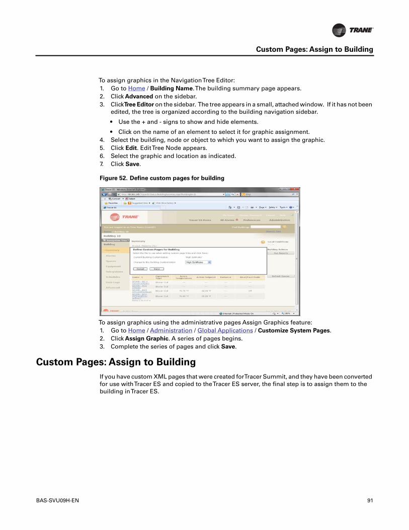
BAS-SVU09H-EN 91
Custom Pages: Assign to Building
To assign graphics in the NavigationTree Editor:1. Go to Home / Building Name.The building summary page appears.2. Click Advanced on the sidebar.3. ClickTree Editor on the sidebar. The tree appears in a small, attached window. If it has not been
edited, the tree is organized according to the building navigation sidebar.
• Use the + and - signs to show and hide elements.
• Click on the name of an element to select it for graphic assignment.4. Select the building, node or object to which you want to assign the graphic.5. Click Edit. EditTree Node appears.6. Select the graphic and location as indicated.7. Click Save.
Figure 52. Define custom pages for building
To assign graphics using the administrative pages Assign Graphics feature:1. Go to Home / Administration / Global Applications / Customize System Pages.2. Click Assign Graphic. A series of pages begins.3. Complete the series of pages and click Save.
Custom Pages: Assign to Building
If you have custom XML pages that were created forTracer Summit, and they have been convertedfor use withTracer ES and copied to theTracer ES server, the final step is to assign them to thebuilding inTracer ES.

92 BAS-SVU09H-EN
Data Logs: Create, Edit, and Delete
To assign a custom page to a building:1. Go to Home / Building Name.The building summary page appears.2. Click Define Custom Pages for Building.The Define Custom Pages for Building popup window
appears.3. Select a custom page for Change to this Building Customization.4. Click Save.
Figure 53. Define custom pages for building
Data Logs
Data Logs: Create, Edit, and Delete
To create standard data logs:1. Go to Home / building name.2. Navigate to the status page containing the data points you want to log.3. Select one or more data points.4. Click Set Up Data Logs. A series of pages begins.5. Complete each page in the series and click Finish at the last page.
To create panel data logs:1. Go to Home / building name.2. Click Data Logs.3. Click Map Panel.4. Select one or more trends.5. Click Next. A series of pages begins.6. Complete each page in the series and click Finish at the last page.
To edit a data log:1. Go to Home / building name.2. Click Data Logs.3. Select a data log.4. Click the name of the data log.The Edit Data Logs Page appears.5. Make changes and click Save.

BAS-SVU09H-EN 93
Data Log Graphs andTables: View, Edit
To delete data logs:
Note: Deleting a data log stops data collection and deletes all logged information.1. Go to Home / building name.2. Click Data Logs.3. Select the data logs.4. Click Delete.
Figure 54. Data logs
Data Log Graphs andTables: View, Edit
To view data log graphs or tables:1. Go to Home / Building Name / Data Logs.2. Select the data logs you want to view (up to 10).3. Click View. A graph appears with default settings.
• Change the value for View Data as toTable to see a tabular view instead of a graph.
• Use the other links on the page to customize the appearance of the graph.
Note: If you navigate away from the Data Log Graph Display after changes have been madeto its appearance, you will lose your changes.
Data Logs: Description and Reference Information
Use data logging inTracer ES to collect historical data from your building control systems.Thisdata can be used for a variety of purposes, from monthly energy usage reporting to equipmenttroubleshooting. After the data is collected, you can view one or more logs as a graph or a tableinTracer ES or you can export the data for use by other applications for storing or presenting thedata.

94 BAS-SVU09H-EN
Data Logs: Description and Reference Information
Types of Data Logs
There are two types of data log: (standard)Tracer ES data logs and Panel data logs:• Tracer ES data logs—This type of data log is initiated by and essentially controlled byTracer
ES.You select a data point of interest and specify details about when the data is sampled, andTracer ES requests and records the data according to your specification.The data is sampledand collected at the same time.
• Panel data logs—A panel data log is a panel trend log being read byTracer ES. Because thetrend log already has a sampling frequency, you only need to specify when the data is collected.And because the data is collected and stored in the panel when it is sampled,Tracer ES doesnot need to collect each sample one at a time.
Time Zones
With standardTracer ES data logs, theTracer ES server applies the time and date information toeach data point. Assuming the user's time zone is set correctly, the time and date stamp on eachdata point will be adjusted to the user's local time.With Panel data logs, the panel applies the timeand date information to each data point. All data points shown inTracer ES will have the panel'slocal time on them, not the user own time zone.
SnapshotTrends
Some panel trend objects are configured to log data only after an event occurs.These are calledsnapshot trends.Tracer ES has no way of knowing when that event has occurred. Similarly, trendsmay be configured to collect data only for part of a day.Tracer ES follows the same algorithm forcollection times for these trend types as with the standard trend objects, despite the fact that theremay not be any new data in the trend.
Failed Panel Communication
IfTracer ES is unable to retrieve data log information from the building control panel, the datarequest will be retried two times. When three attempts have failed,Tracer ES stops attempting toperform the scheduled data collection and a failure message is added to the system log with thefollowing information:• Date and time the failure occurred• Name of the building thatTracer ES was requesting data from• Name of the data log thatTracer ES was collecting data for• Any available communications error details
Tracer ES will attempt to collect data from the building controller at the next scheduled datacollection time. For panel data logs, it will occur 15 minutes after the failed attempt.
Tracer ES Server Failure
IfTracer ES is not operational at the time it is scheduled to collect data from a panel data log, it willcollect the data it missed when it is operational again.

BAS-SVU09H-EN 95
Data Log Attributes: Create, Assign
Data Log Staging
To minimize spikes in network traffic,Tracer ES monitors its scheduled communications tasks towarn you of possible bottlenecks. So, when you add new data logs, they system examines thespecific collection times compared to the number of data points and buildings involved andevaluates the system performance impact. If the requested collection times would degradenetwork or system performance,Tracer ES will inform you of these concerns and suggestalternative collection times to alleviate the stress. If you see the warning, your choices will be:• Proceed as specified and accept network risks.The system attempts to honor the data log
request, but may limit data collections if the system begins to overload.• Change the parameters of the data log.• Allow the system to stage the requests.The data requests are sent out in smaller batches and
the system monitors its performance before releasing each batch.This reduces the spike ofnetwork traffic. In this case the data log may show data and time stamps that start severalminutes later than expected.
Collection Notification
Some building control panels have an option to communicate with the workstation to request thatthe workstation collect the data in its data log.Tracer ES supports this notification for all buildingcontrol panel types. If the user-specified or algorithmic intervals selected for the data log arescheduled to collect the data before a collection notification is received,Tracer ES collects the datalog information at that time rather than waiting for the collection notification. When you create apanel data log,Tracer ES subscribes to this service automatically when applicable.
Data Log Attributes: Create, Assign
Data log attributes are a tool that can make it easier for you to locate or identify data logs with someproperty in common. You can create data log attributes with a name of your choosing. After theyare created, a data log attribute can be assigned to one or more data logs. When data logs are listedin tables one column of the table contains the data log attributes, permitting you to sort the tableon attribute values.
To create a data log attribute:1. Go to Home / Administration / Global Applications / Manage Data Log Attributes.2. Click Add New Data Log Attribute.The CreateTracer ES Data Log Attribute pop-up window
appears.3. Type a name for the new attribute in the New Attribute Name field.4. Click Save.
To assign data log attributes globally to one or more existing data logs:1. Go to Home / Administration / Global Applications / Manage Data Log Attributes.2. Select one or more data log attributes.3. Click Assign.The Assign Attributes to Data Logs page appears.4. Place a check mark next to the data logs you want to assign to the attributes you selected earlier.5. Click Save.

Trane optimizes the performance of homes and buildings around the world. A business of Ingersoll Rand, theleader in creating and sustaining safe, comfortable and energy efficient environments, Trane offers a broadportfolio of advanced controls and HVAC systems, comprehensive building services, and parts. For moreinformation, visit www.Trane.com.
Trane has a policy of continuous product and product data improvement and reserves the right to change design and specifications without notice.
We are committed to using environmentally
conscious print practices that reduce waste.
© 2012Trane All rights reserved
BAS-SVU09H-EN 31 May 2012
Supersedes BAS-SVU09F-EN (25 Oct 2011)
Licensing
Tracer ES Licensing
Tracer ES is licensed based upon the number of building panels it will control.Typically,Tranepanels (specificallyTracer Summit BCUs,Tracer panels andTracker panels) can be identified on thenetwork as single panels. But non-Trane panels andTracer SC controllers appear on the networkas a collection of I/O points, not a single panel.To accommodate the difference in how the panelsappear on the network, licenses are granted using the following formula:• Trane BACnet devices require one license each, butTracer Summit Communications Bridges
andTracer UCs do not require licenses.• Non-Trane devices require between 1/1500 and one license each, depending upon the number
of BACnet I/O points in them.
• Each I/O point counts as 1/1500 of a license.
• A single non-Trane BCU-equivalent panel with more than 1500 I/O points requires only onelicense.
• BACnet object types such as calendar or trend objects do not require a license, but they areonly shown inTracer ES if they reside in a device that is licensed byTracer ES.
License File: Install
TheTracer ES license is contained within a file created byTrane. Once it is acquired, it must beinstalled in the system before it can be used.

BAS-SVU09H-EN 97
License File: Install
To install a license:1. Locate the electronic license file and copy it somewhere on the system where you will be able
to find it.2. Go to Home / Administration / System Maintenance / UploadTracer ES System License File.3. Click Choose File.4. Locate and select the license file.5. Click Open.The file name should appear next to the Choose File button.6. Click Finish.
Figure 55. UploadTracer ES system license file

98 BAS-SVU09H-EN
Licensing Information: View, Register, or Change
Licensing Information: View, Register, or Change
License information is information provided when the software is registered, including customerinformation (name, address, telephone number, and e-mail address) and the license customercode provide byTrane.• To view the current license information, go to Home / Administration / System Maintenance /
ManageTracer ES Licensing / View License Information.• To register for the first time, or to change the current license information, go to Home /
Administration / System Maintenance / ManageTracer ES Licensing / Register Site License.
Figure 56. RegisterTracer ES site license
License Administration: View or Change Licence Allocation
Users with sufficient permission can allocate available licences to the buildings discovered by thesystem. Reasons to allocate or reallocate licenses include the following:• You purchase additional licenses.• You add buildings or equipment to the system.• You want to transfer the license permission from one panel to another.

BAS-SVU09H-EN 99
Home Page Custom Links: Define, Remove
To view or edit the current license allocation:1. Go to Home / Administration / System Maintenance / ManageTracer ES Licensing /View Panel
Licensing.The View Panel Licensing page shows:
• The number of licenses allocated to your system and the number actually being used.
• The name and other details about each discovered panel, how much of your license it coulduse, and whether it is actively using any.
2. Activate or deactivate panels as desired by clicking theYes or No radio buttons in the Activecolumn. As soon as you click one of the radio buttonsTentative Licenses Used appears onthe screen to indicate how your changes affect the total number of available licenses, but yourchanges are not yet saved.
3. To keep your changes, click Save.To revert to the previous allocation without making anychanges, click Back.
Figure 57. View panel licensing
Customizing
Home Page Custom Links: Define, Remove
There are two types of custom links that can appear on the right side of theTracer ES home page.The Recent Visit list shows the last five places you have visited, and the custom links list, whichhas a name of your choice, shows four links to custom destinations for which you can also providea custom name. Creating a list of custom links can be useful if you would like quick access to a pagethat you regularly use.
To define or edit home page custom links:1. Go to Home / Administration / Global Applications / Customize System Pages.2. Click Define Home Page Custom Links. A series of pages begins.3. Complete the series of pages and click Finish on the last page.

100 BAS-SVU09H-EN
System Parameters: View, Edit
To remove home page custom links:1. Go to Home / Administration / Global Applications / Customize System Pages.2. Click Remove Home Page Custom Links. A popup window will require you to confirm the
action.
Figure 58. Customize System Pages
System Parameters: View, Edit
The system parameters are several small groups ofTracer ES program settings that apply to allusers of the system. Categories of parameters include the following:• Building discovery BACnet device IDs• Site synchronization scheduling• Alarm priority mapping path, audible alarm setting, and path to audible alarm sound file.• Global point control log settings• All points in override included priorities• E-mail server settings and credentials• Time synchronization scheduling• Status application variance algorithm• User security parameters (username and password settings)• General display settings (system default language)

BAS-SVU09H-EN 101
System Parameters: View, Edit
To view or edit the system parameters:1. Go to Home / Administration / System Maintenance / System Parameters.The System
Parameters page appears.2. Click Edit.The Edit System Parameters page appears. All parameters can be edited.3. Make change as desired.4. Click Save.
Figure 59. System parameters

102 BAS-SVU09H-EN
Buildings: Customize Grouping
Buildings: Customize Grouping
You can specify the way buildings are organized on theTracer ES home page in one of three waysaccording to your preference.• No grouping - buildings are listed in alphabetical order.• One grouping level - buildings are grouped by a building attribute of your choice.• Two grouping levels - buildings are grouped by two building attributes of your choice (one
general and one specific).
To customize the building grouping:1. Go to Home / Administration / Global Applications / Customize System Pages / Customize
Building Grouping.The Customize Building Grouping page appears.2. Select the number of index levels.3. Select the general and specific grouping attributes, if required: If you selected one level, select
the general grouping attribute; if you selected two levels, select a general and a specificgrouping attribute.
4. Click Finish.
Figure 60. Customize building grouping
ProcessTracker: View, Clear Entries, Cancel Processes
The ProcessTracker is a way for you to keep track of progress whenTracer ES is sendinginformation to building panels. Whenever you create or make a change that must be written to oneor more panels, the ProcessTracker creates an entry for the new process, and opens the ProcessTracker in a new window.
Note: If the ProcessTracker is already open in a window behind the active window, it willnot automatically move in front of the active window. If you do not see the ProcessTrackerwhen you expect it to open, look behind the active window.

BAS-SVU09H-EN 103
Database: Manage Size
To open the process tracker window and view your completed and in-progress processes:• Click .
Figure 61. ProcessTracker
Note: EachTracer ES user has his or her own process tracker data.You will not see processesthat were initiated by other users who were logged into a different user account.To seeactivities performed by other users, view the SystemTask log.
To remove entries from the process tracker:1. Click to open the ProcessTracker.2. Do one of the following:
• To clear a completed single process, click Clear on the same row as the process.
• To clear all completed processes in the ProcessTracker, click Clear All.
Note: Cleared processes are permanently removed from the ProcessTracker, but theprocess is not stopped.
To cancel processes:1. Click to open the ProcessTracker.2. Click Cancel on the same row as the process.
Database: Manage Size
Overview
This feature is designed forTracer ES installations using a SQL Express database but can be appliedto all SQL database types. SQL Express does not provide automatic database maintenance plans.The database is allowed to grow until it reaches a size limit that prevents further data storage. User-defined data log collection, alarm collection, global point control, system, and user change logscontribute to database growth.This feature will remove these data growth components from thedatabase.There are two components to Manage Database Size: Database Size Management andApplication Log Management.
Database Size Management
Database Size management can be applied to all SQL database types. It cannot be disabled forSQL Express databases. With a new installation ofTracer ES, application data is automaticallydeleted based on a schedule. You can change the settings to one of the choices described below.
104 BAS-SVU09H-EN
Database: Manage Size
CAUTION: Selecting one of the options to delete old data at this time will result in data log valuesbeing permanently deleted from theTracer ES database.The default value for SQL Expressdatabases automatically enables Delete old data based on database file size of 3.5 GB (SQLExpress 2005) or 9.5 GB (SQL Express 2008) and will retain 90 days worth of data.
NOTE:The maximum database size cannot exceed 1000 Gigabytes.• Do not delete old data - select this option if you wantTracer ES to continue to gather data
without deleting any. Be aware that disk space usage and system performance can both beaffected if you do not delete any data.
• Delete old data based on a schedule - data beyond a specified age is routinely deletedaccording to a specified schedule.
• Delete old data based on database file size - the system checks the database at specifiedintervals and deletes the oldest data first to reduce the database to a size smaller than themaximum size.
Application Log management
Application Log Management is applied to all SQL database types.You cannot select No or setthe value to unlimited for any application log setting for SQL Express databases. You can limitthe number of each type of log that is retained in the database independent of the age of the dataor the size of the database. For example, you could specify that no more than 100 user changesare retained in the database; to make room for the 101st user change log record, the database wouldautomatically delete the oldest record to make room for the newest. Valid selection for Limit areYes and No. Valid entries for Maximum Log Entry range from 1 – 100,000. Setting limit to Noautomatically changes the Maximum Log Entry value to Unlimited.You cannot set the Limit to Nofor SQL Express databases.
Viewing and Making changes
To view and change the database size management settings:1. Go to Home / Administration / System Maintenance / Manage Database Size.The current
database management settings are shown on the page.2. Click Edit to make changes.
You can also use the Manage Database Size page to execute the currently scheduled settingswithout waiting for the scheduled time to expire:1. Go to Home / Administration / System Maintenance / Manage Database Size.The current
database management settings are shown on the page.2. Click Run Now to execute the settings.

BAS-SVU09H-EN 105
Database: Manage Size