Embed Size (px)
Citation preview

TraceNet™ TC Series Control System
TCM18 Panel Installation, Start-Up, Operating, and Maintenance Guide
Thermon, Inc.
TraceNet™is a registered trademark of Thermon, Inc.
PN 50316-0120
PN 50316-0120
PRODUCT WARRANTY INFORMATION
The seller warrants all equipment manufactured by it to be free from defects in workmanship or material under normal use and service. If any part of the equipment proves to be defective in workmanship or material and if such part is, within 12 months of the date of shipment from sellers factory, and if the same is found by the seller to be defective in workmanship or material, it will be replaced or repaired, free of charge, F.O.B. the seller’s factory. The seller assumes no liability for the use or misuse by the buyer, his employees, or others. A defect within the meaning of this warranty in any part of any piece of equipment shall not, when such part is capable of being renewed, repaired, or replaced, operate to condemn such piece of equipment. This warranty is in lieu of all other warranties (including without limiting the generality of the foregoing warranties of merchantability and fitness for a particular purpose), guarantees, obligations, or liabilities expressed or implied by the seller or its representatives and by statue or rule of the law.
TCM18 Panel Installation, Start-Up, Operating and Maintenance Guide
©2014 Thermon, Inc. All Rights Reserved.
This guide, as well as the firmware described in it, is furnished under license and may only be used or copied in accordance with the terms of such license. The information in this guide is furnished for informational use only, is subject to change without notice, and should not be construed as a commitment by Thermon, Inc. Thermon assumes no responsibility or liability for any errors or inaccuracies that may appear in this guide.
This information is subject to change without notice. It is recommended that a quick check of the current revision status be done at www.Thermon.com prior to proceeding.
This guide is written and designed at Thermon, Inc. 100 Thermon Drive, San Marcos, TX 78667-0609, USA.

Contents
Chapter 1: Introduction . . . . . . . . . . . . . . . . . . . . . . . . . . . . . . . . . . . . . . . . . . . . . . . . . . . . . . . . . . . . . . . . . . . . . . . . . . . . . . . . . . . . . . . . . 1
Chapter 2: Specifications . . . . . . . . . . . . . . . . . . . . . . . . . . . . . . . . . . . . . . . . . . . . . . . . . . . . . . . . . . . . . . . . . . . . . . . . . . . . . . . . . . . . . . . . . 3
Chapter 3: Module Connections . . . . . . . . . . . . . . . . . . . . . . . . . . . . . . . . . . . . . . . . . . . . . . . . . . . . . . . . . . . . . . . . . . . . . . . . . . . . . . . . . . . . . . . . . 7
Chapter 4: Field and Panel Wiring . . . . . . . . . . . . . . . . . . . . . . . . . . . . . . . . . . . . . . . . . . . . . . . . . . . . . . . . . . . . . . . . . . . . . . . . . . . . . . . . . . . . . . . . . 12
Chapter 5: Monitoring Heat Tracing Circuit Status . . . . . . . . . . . . . . . . . . . . . . . . . . . . . . . . . . . . . . . . . . . . . . . . . . . . . . . . . . . . . . . . . . . . . . . . . . . . . . . . . . . . . . . . . 16
Chapter 6: Accessing Heat Tracing Circuit Information . . . . . . . . . . . . . . . . . . . . . . . . . . . . . . . . . . . . . . . . . . . . . . . . . . . . . . . . . . . . . . . . . . . . . . . . . . . . . . . . . . . . . . . . . 22
Chapter 7: Programming the TCM18 . . . . . . . . . . . . . . . . . . . . . . . . . . . . . . . . . . . . . . . . . . . . . . . . . . . . . . . . . . . . . . . . . . . . . . . . . . . . . . . . . . . . . . . . . 27
Chapter 8: Heat Trace Control and Monitoring . . . . . . . . . . . . . . . . . . . . . . . . . . . . . . . . . . . . . . . . . . . . . . . . . . . . . . . . . . . . . . . . . . . . . . . . . . . . . . . . . . . . . . . . . 46
Chapter 9: The TCM18 in Process Sensing Applications . . . . . . . . . . . . . . . . . . . . . . . . . . . . . . . . . . . . . . . . . . . . . . . . . . . . . . . . . . . . . . . . . . . . . . . . . . . . . . . . . . . . . . . . . 48
Chapter 10: The TCM18 in Ambient Sensing Application . . . . . . . . . . . . . . . . . . . . . . . . . . . . . . . . . . . . . . . . . . . . . . . . . . . . . . . . . . . . . . . . . . . . . . . . . . . . . . . . . . . . . . . . . 51
Chapter 11: The TCM18 Data Highway Communication . . . . . . . . . . . . . . . . . . . . . . . . . . . . . . . . . . . . . . . . . . . . . . . . . . . . . . . . . . . . . . . . . . . . . . . . . . . . . . . . . . . . . . . . . 53
Chapter 12: System Start-Up . . . . . . . . . . . . . . . . . . . . . . . . . . . . . . . . . . . . . . . . . . . . . . . . . . . . . . . . . . . . . . . . . . . . . . . . . . . . . . . . . . . . . . . . . 54
Chapter 13: Maintenance . . . . . . . . . . . . . . . . . . . . . . . . . . . . . . . . . . . . . . . . . . . . . . . . . . . . . . . . . . . . . . . . . . . . . . . . . . . . . . . . . . . . . . . . . 55
PN 50316-0120

PN 50316-0120
Chapter 14: Notes . . . . . . . . . . . . . . . . . . . . . . . . . . . . . . . . . . . . . . . . . . . . . . . . . . . . . . . . . . . . . . . . . . . . . . . . . . . . . . . . . . . . . . . . . 60
Chapter 15: More Information . . . . . . . . . . . . . . . . . . . . . . . . . . . . . . . . . . . . . . . . . . . . . . . . . . . . . . . . . . . . . . . . . . . . . . . . . . . . . . . . . . . . . . . . . 62
Appendix A: Trouble Shooting Tips . . . . . . . . . . . . . . . . . . . . . . . . . . . . . . . . . . . . . . . . . . . . . . . . . . . . . . . . . . . . . . . . . . . . . . . . . . . . . . . . . . . . . . . . . 63
Appendix B: Temperature and Current Limits . . . . . . . . . . . . . . . . . . . . . . . . . . . . . . . . . . . . . . . . . . . . . . . . . . . . . . . . . . . . . . . . . . . . . . . . . . . . . . . . . . . . . . . . . 75
Appendix C: Advanced Features of the TCM18 Ambient Control . . . . . . . . . . . . . . . . . . . . . . . . . . . . . . . . . . . . . . . . . . . . . . . . . . . . . . . . . . . . . . . . . . . . . . . . . . . . . . . . . . . . . . . . . 77
Appendix D: Typical TCM18 Control Applications . . . . . . . . . . . . . . . . . . . . . . . . . . . . . . . . . . . . . . . . . . . . . . . . . . . . . . . . . . . . . . . . . . . . . . . . . . . . . . . . . . . . . . . . . 80
Appendix E: Utilities . . . . . . . . . . . . . . . . . . . . . . . . . . . . . . . . . . . . . . . . . . . . . . . . . . . . . . . . . . . . . . . . . . . . . . . . . . . . . . . . . . . . . . . . . 90
Appendix F: Markings for Hazardous Locations (Potentially Explosive Atmospheres)
. . . . . . . . . . . . . . . . . . . . . . . . . . . . . . . . . . . . . . . . . . . . . . . . . . . . . . . . . . . . . . . . . . . . . . . . . . . . . . . . . . . . . . . . . 91

11 PN 50316-0120
Note: All personnel should be properly trained and qualified to safely install, service, operate, and program this TraceNet heat tracing control panel as well as to operate the associated heat tracing system.
1 Introduction
The following serves as a general guide and overview on the installation, startup, operation, and maintenance of a TraceNet TC Series heat tracing control panel utilizing TCM18 control modules. This guide shall be used in conjunction with the project specific control system drawings and any other standard installation instructions/guides provided. In the unlikely event that a conflict or uncertainty arises, contact the Thermon engineering support personnel assigned to this project to clarify.
THE PANEL LOCATION A wide variety of TraceNet TC Series panel configurations are possible. The TraceNet modules are designed to operate in ambients ranging from -40◦F (-40◦C) to 140◦F (60◦C) and higher. The TraceNet panels can be located in site locations having electrical classifications ranging from ordinary to hazardous. Installation Category II, at altitudes up to 2000 m. The actual panel markings provided with the panel will detail the design intended specific location requirements. The module may be used in pollution degree 2 or better.
INITIAL INSPECTION AND HANDLING
Upon receiving the TraceNet TC Series panel, it is important to confirm that the contents of the shipping containers agree with the shipping documents and with the purchase order. Also, it is important to check the shipped container exterior and packing materials for any possible freight damage. Where damage is observed, take photos and notify the carrier as well as your nearest Thermon engineering support center before proceeding further.
After carefully removing the panel from its shipping container, move the panel to its selected location utilizing the pallet base and the securement strapping provided using a lift truck/forklift. Where lifting eyes are provided on the panel, they should be used when handling.

2 PN 50316-0120
Note: For installation requirements specific to purged panels, please see Appendix F. TCM18 Control and Monitoring Module
Where the panel has external heat sinks to dissipate the heat generated by solid state relay switching, it is recommended that a minimum of 6” (150 mm) of space be allowed between sinks and walls or other panels to minimize heat buildup at the heat sinks. Where heat sinks are present on adjacent panels, allow 12” (300 mm) spacing between heat sinks for sufficient natural air movement.
Adequate door clearance for service work entry and conduit panel entries should be anticipated when establishing the exact panel location. When the panel is located outdoors, a concrete base pad of sufficient height to avoid potential standing water should be constructed.
Once the panel has been properly located, refer to the project specific installation details for the recommended floor mounting as well as wall mounting details.
Once bolted in place, the panel is ready for final configuration, wiring, and site required assembly. Note that the TCM18 control and monitoring module is normally shipped in a separate container to minimize any undue impact stress during shipment. It should be removed from its shipping container again being attentive to any shipping damage that may have occurred during its transit. The TCM18 mounting details are likewise provided in the project specific drawing details.

3 PN 50316-0120
2 Specifications
The general TraceNet TC Series panel specifications are as given below.
Interior panel operating ambient range -40◦F to 140◦F (-40◦C to 60◦C) Exterior panel operating ambient range -40◦F to 131◦F (-40◦C to 55◦C) Ambient storage range -40◦F to 158◦F (-40◦C to 70◦C) Relative humidity range 0 to 90% Non Condensing Nominal instrument control voltage 100 to 240 Vac, 50/60 Hz Temperature sensor types 100 Ohm 3 Wire Platinum RTD Control temperature range -200◦F to 1112◦F (-129◦C to 600◦C) Maximum power consumption of TCM18 module
70 Watts
Current ratings in hazardous (classified) locations based on TraceNet TC Series panels for up to 72 circuits are as follows1:
Maximum Panel Exterior Ambient (◦C)
For: 1 - 36 Circuits For: 37 - 72 Circuits Maximum Allowable Average Amps per Relay
(Calculated for each side of enclosure)2
40 22.2 18.0 45 21.0 16.8 50 19.7 15.6 55 18.3 14.3

4 PN 50316-0120
Current ratings in nonhazardous (ordinary) location based on TraceNet TC Series panels for up to 72 circuits are as follows1:
Maximum Panel Exterior Ambient (◦C)
For: 1 - 36 Circuits For: 37 - 72 Circuits Maximum Allowable Average Amps per Relay
(Calculated for each side of enclosure)2
20 27.0 22.7 25 25.8 21.6 30 24.7 20.4 35 23.5 19.2 40 22.2 18.0 45 21.0 16.8 50 19.7 15.6 55 18.3 14.3
Note 1: Contact the manufacturer for the maximum allowable amps per relay for custom enclosure sizes. Note 2: Based on factory panel wiring rated for 105◦C.
The TCM18 has the following operating specifications:
Rated supply voltage 100 to 240 Vac, 50/60 Hz Display 4–7/8” (124 mm) x 1–3/4” (44 mm) LCD STN with LED
backlight Touch pad Membrane switch stainless steel dome tactile keys Control capacity Eighteen heat tracing circuits
Temperature inputs Up to two 3 wire 100 Ohm Platinum RTD’s 32◦F (0◦C) per heat trace circuit
Temperature control range
-200◦F to 1112◦F (-129◦C to 600◦C)
Communication Dual RS485 ports Communication protocol
ModBus ASCII or RTU
Communication rate 9600 to 57600 Baud

5 PN 50316-0120
Auxiliary power output 24 Vdc at 0.5 Amps Panel ambient operating temperature range Storage temperature range Alarm relay outputs
-40◦F (-40◦C) to 131◦F (55◦C)
-40◦F (-40◦C) to 158◦F (70◦C)
Option U 3 sealed dry contact relays rated 0.4A resistive at 24 Vdc Option A 3 sealed dry contact relays rated 0.5A resistive at 100-240
Vac Control relay outputs Up to eighteen DC outputs each having a sink current
capability of 100 mA 12VDC (24 Vdc optional by programming)
Control options On/Off, On/Off with Soft Start, Proportional, and Ambient Proportional Control
LCD heated display 1-3/4” (44 mm) x 4.875” (124 mm)
TCM18 module operating temperature range
-40◦F (-40◦C) to 140◦F (60◦C)
The PM6 has the following operating specifications:
Circuit control capacity up to six heat trace circuits
Single pole relay switching capacity 30 Amperes at 240 Vac*
Dual pole relay switching capacity 15 Amperes at 240 Vac*
Maximum power consumption less than 3 Watts
Relay power connection 40-Pin header ribbon cable
Ground/earth leakage test connection 10-Pin header ribbon cable
Maximum storage temperature 185◦F (85◦C)
Minimum storage temperature -40◦F (-40◦C)
Oper. ambient temp. range -40◦F (-40◦C) to 158◦F (70◦C)

6 PN 50316-0120
Power terminal connections 20 to 6 AWG (0.5 to 10mm2), 630V
Printed circuit board conformally coated
Alarm two 24 Vdc, 350 mA each
* Rating based on heat sinks installed external to panel. Relay ratings have a reduced rating when sinks are used internal to panel. Higher voltage rating relays are also available as an option.
The RM6 has the following operating specifications:
Maximum storage temperature 185◦F (85◦C)
Minimum storage temperature -40◦F (-40◦C)
Oper. ambient temp. range -40◦F (-40◦C) to 158◦F (70◦C)
Terminal connections 28-12 AWG (0.14 to 2.5 mm2)
Earth leakage test connection 10-Pin header ribbon cable
Relay connection 40-Pin header ribbon cable The RTB6 has the following operating specifications:
Maximum storage temperature 185◦F (85◦C)
Minimum storage temperature -40◦F (-40◦C)
Oper. ambient temp. range -40◦F (-40◦C) to 158◦F (70◦C)
Terminal connections 28-12 AWG (0.14 to 2.5 mm2)
Maximum RTD capacity six

7 PN 50316-0120
3 Module Connections Due to its flexible architecture, a variety of TraceNet TC Series panel configurations are available. The specific project drawings should be followed when installing the power supply and field distribution wiring into the TraceNet panel as well as when installing the data highway interface wiring. As an overview and to provide a more general understanding of the inner workings of this panel, the following general connection diagrams are provided.
The TCM18 Connections
The TCM18 is the TraceNet interface to the outside world. It monitors the condition of the heat tracing circuits as well as the heat traced piping temperatures and allows interrogation of heat trace status, alerts the operator to alarm and trip events, and allows the changing of the operating parameters and system configuration.
The TCM18 is designed to be mounted internal to the panel on a panel swing out or on the panel door (if indoors), or behind an instrument access door if outdoors. TCM18 module nominal dimensions are as follows:
Figure 1: TCM18 Control and Monitoring Module

8 PN 50316-0120
The TCM18 wiring and connections are located on the rear of the TCM18 module and are described as below:
Figure 2: Wiring and Connection Details on the TCM18

9 PN 50316-0120
The RTB6 Module Connections The RTB6 module allows the connection of six 3-wire 100 Ohm platinum RTD inputs to the TraceNet control system. The RTB6 circuit board is a passive device which communicates the discrete temperature inputs into a 26-pin bundled ribbon cable which then interconnects to a TCM18 module.
The connections within a TraceNet panel for the RTB6 are shown in the illustration which follows.
Figure 3: RTB6 Wiring and Connections

10 PN 50316-0120
The PM6 Connections The PM6 serves as the heat trace power solid state switching module for a TraceNet TCM18 controller. It includes the heater and ground current measurement transformers, solid state heat trace control relays, and the heat dissipating heat sink. This module includes a ground leakage functional test circuit. In addition, alarm and trip output capability to indicating lights on the panel front door are also provided. The module connections for the PM6 are as detailed in the following illustration.
Figure 4: PM6 Wiring and Connections

11 PN 50316-0120
Note: When receiving a new TraceNet TC Series control panel shipment, it is recommended that all module connections within the panel be re-torqued to the recommended tightness levels as provided in the project panel drawing and in Table 1 Chapter 4. Occasionally, it is possible that handling and shipment can loosen some wiring terminations or components cables. Servicing allowed for removable electrical connectors only when the area is known to be free of explosive atmospheres.
The RM6 Connections The RM6 is a DIN rail mounted six circuit relay interface module for linking to individual solid state or mechanical relays via ribbon cable from the TCM18 controller. The RM6 includes individual terminal strips which allow the interconnection of individually mounted heater and ground current sensing transformers. This module is primarily used where custom current transformers, solid state relays with integral heat sinks, or individual pilot and mechanical relays are to be used. The module connections for the RM6 are as detailed in the following illustration.
Figure 5: RM6 Wiring and Connections

12 PN 50316-0120
4 Field and Panel Wiring
For a successful installation of a TraceNet TC Series heat tracing control and monitoring panel, a number of equally critical parts of the system must be installed properly. Areas requiring close attention are the heat trace and insulation, the RTD temperature sensor installation, the distribution of the field RTD and power wiring, and the installation and routing of wiring inside the TraceNet panel.
Note: The heat tracing system installation shall be in accordance with the electrical area classification requirements as well as shall conform to the latest requirements as detailed in applicable heat tracing standards, the local Electrical Code and plant standard practices. Where conflicts arise, contact the project engineer for resolution.
Heat Trace and Insulation Installation
All heat trace circuits and insulation shall be installed in accordance with project installation details provided. In addition, refer to the Electric Heat Tracing Maintenance and Troubleshooting Guide (Thermon Form No. 20745) for general procedures and installation tips.
RTD Installation and Wiring
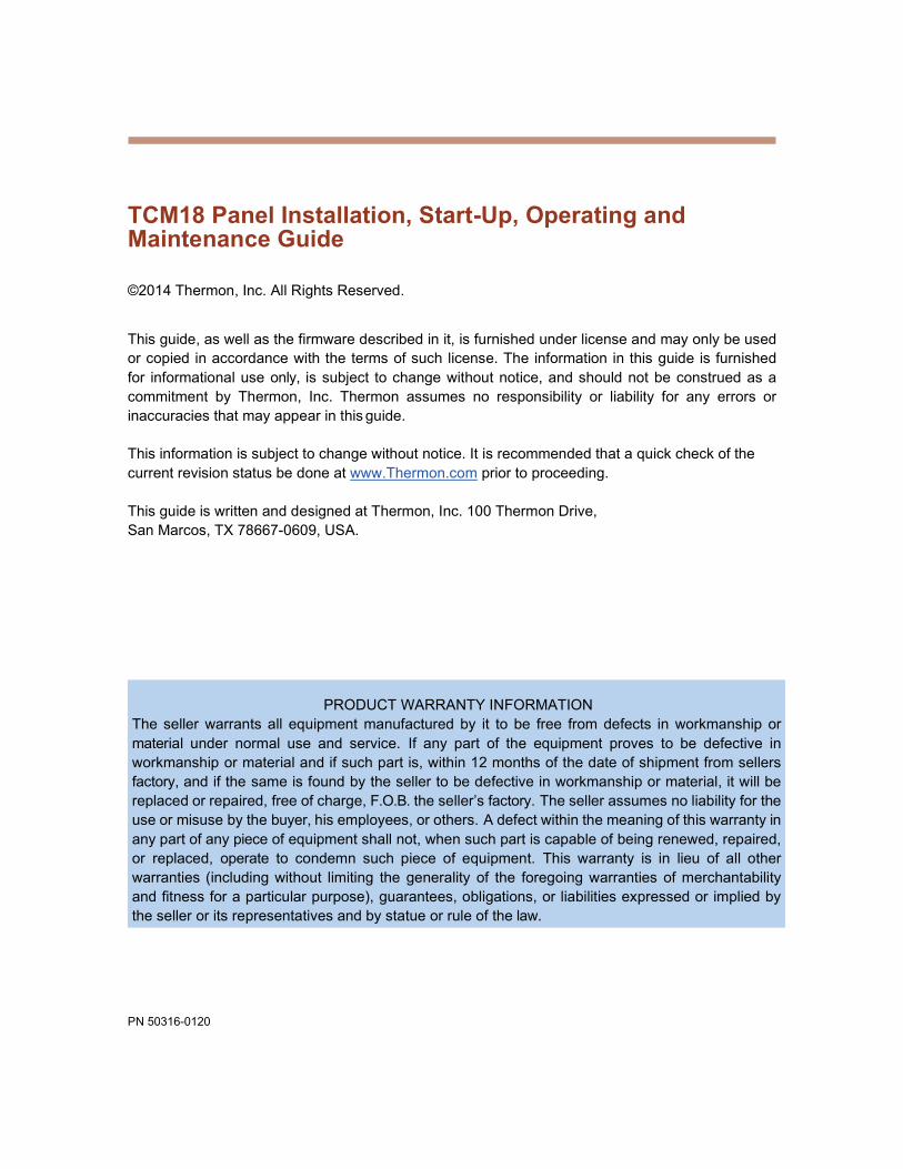
RTD control sensors should generally be installed on the process lines or in ambient (where ambient sensing is applied) in a location that is most representative of the entire heat trace circuit. In general, it is recommended that the sensors not be located at heat sinks such as pipe supports, pumps, and valves as the control system response needs to be based on the majority of the process line. The RTD control sensor location on the process piping should follow the guidelines detailed in Figure 6.
13 PN 50316-0120
Figure 6: RTD Sensor Location
Where limiter RTD sensors are installed on the process piping it should follow the guidelines above. In cases where the limiter is to be installed on the heater itself, it is important to recognize that an offset should be anticipated in the limiter trip value to allow for sensor reading error and overshoot.
As a general rule, field RTD wiring and power wiring should not be routed in the same conduit or proximity in a tray as the temperature signals can become distorted and result in improper readings.
Power Distribution Wiring and Breakers
All field power wiring materials used shall be suitable for the intended service and shall be rated for insulation service temperatures up to and exceeding 221◦F (105◦C) unless otherwise higher values are noted in project specifications. Power supply wiring from the power transformers to the power distribution panel and distribution wiring to the heat trace circuits shall be rated for the heat trace use voltage or higher and sized sufficiently large in wire size to minimize voltage drop. Circuit breakers if not already supplied in the TraceNet panel should be selected based on the heat trace cable type being used, the service voltage, and the circuit current draw characteristics. It is especially important when using self-regulating cable to make sure that the circuit breaker response curve type is coordinated with the startup characteristic of the heat trace cable in a cold start condition. All distribution wiring connections should be tightened using a torque indicating screwdriver to the levels indicated in Table 1.

14 PN 50316-0120
Location of Terminals Torque Values (Typical)* RTB6 5.3 to 7.0 in. lbs. (0.60 to 0.79 N-m) PM6 12.5 to 13.5 in. lbs. (1.41 to 1.53 N-m) Distribution Equipment 13.2 to 15.9 in. lbs. (1.49 to 1.80 N-m)
*Required torque values may vary depending on individual panel designs and size of terminals. Refer to project documentation for additional information.
Table 1: Recommended Torque Values
TraceNet Panel Wiring TraceNet TC Series panels are configured and prewired into an integrated heat trace control and monitoring system. Clean terminal strips are provided to facilitate the field wiring into the panels. Refer to the project specific panel drawings when installing the field wiring within the panel. Field wiring is conventionally shown by dashed lines. All field power wiring materials used shall be suitable for the intended service and shall be rated for insulation service temperatures up to and exceeding 221◦F (105◦C) unless otherwise higher values are noted in project specifications. All TraceNet components terminal block connections should be tightened using a torque indicating screwdriver to the levels indicated in Table 1.
When a panel is rated for IP54 and/or NEMA-4, entries into panels must meet IP54 and/or NEMA-4 ingress protection levels to maintain the environmental rating of the panel.
Serial Communication Wiring
TraceNet TC Series panels may be linked together for communications with a RS485 communication cable at distances up to 4000 feet (300 m.). In addition, a termination module should be used at each end of the RS485 network. The recommended communication cables for use in the RS485 network are as given in Table 2.
15 PN 50316-0120
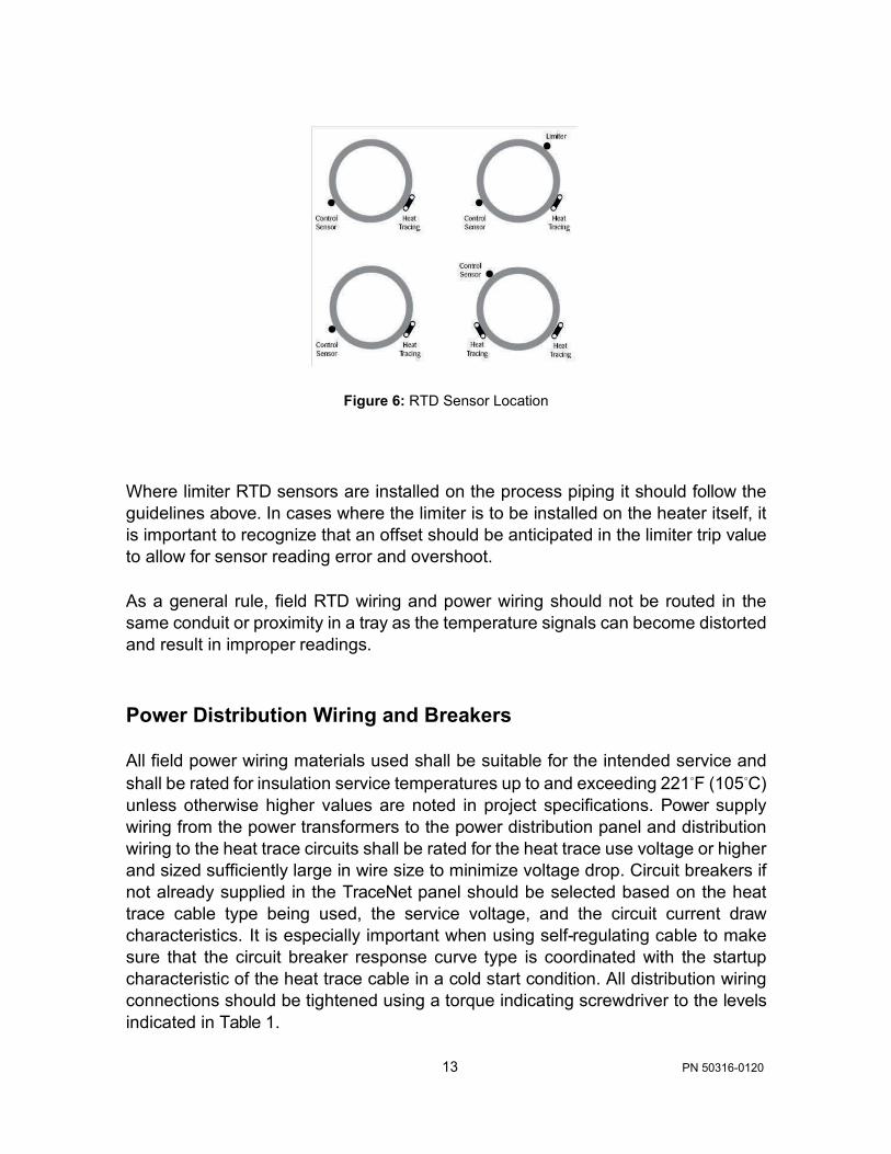
Cables for RS485 Communication The following data highway cables listed in Table 2 are recommended.
CableType Recommended 120 Ohm, -20 to +60 C 22AWG FHDPE insulation PVC outer jacket
Belden 3107A or equal
120 Ohm, -30 to +80 C 24AWG PE insulation PVC outer jacket
Belden 9842 or equal
120 Ohm, -70 to +200 C 24AWG Teflon FFEP insulation Teflon FEP outer jacket
Belden 89842 or equal
Note all these products are designated as 120 ohm impedance for balanced line communication uses.
Table 2: RS485 Cable Types

16 PN 50316-0120
THERMON TCM18 COPYRIGHT 2013
5 Monitoring Heat Tracing Circuit Status
All interfacing to the TCM18 and the heat tracing circuit information is via the dedicated tactile feel membrane touchpad and the companion four line LCD display as shown in Figure 7
Figure 7: TCM18 Control and Monitoring Module Front Panel
On power up, the TCM18 will display the following start-up screen message:
Figure 8: TCM18 Start-Up Screen

17 PN 50316-0120
MAINTAIN TEMP= 60◦C HEATER ON 80% 12.0A
TEMP= 61◦C CKT 7
After this start-up message, the TCM18 will immediately proceed to operation in its SCAN MODE.
The TCM18 will operate in a heat tracing circuit SCAN MODE during normal operation. That is, the LCD display will automatically scroll through each enabled heat tracing circuit number, indicating the actual measured temperature and the control set point for maintain temperature on the first two display screen lines. The third display screen line will indicate the heater status (ON % or OFF) and the heat tracing circuit heater current value. The fourth display screen line will indicate any alarm(s) present on the circuit displayed. Where multiple alarm events occur on a circuit, the TCM18 will display only one alarm message at a time until all have been cleared. A typical SCAN MODE screen when the heat tracing circuit is operating normally is as shown below in Figure 9:
Figure 9: Typical TCM18 information when in SCAN MODE
Note that the fourth message line on the display screen will be empty as long as there are no alarm or trip conditions present on a given circuit. During SCAN MODE, the TCM18 will sequence through all enabled heat tracing circuits beginning with the first circuit and then loop back to the first circuit after displaying the last circuit and repeat the scanning process. A summary of all possible alarm messages follows.
Message Explanation
RTD FAULT ALARM
The RTD reading is out of the range when the resistance value exceeds 313.7 Ohms or is less than 48.46 Ohms. In this case, either the RTD has not been connected or has opened or shorted in service.
18 PN 50316-0120
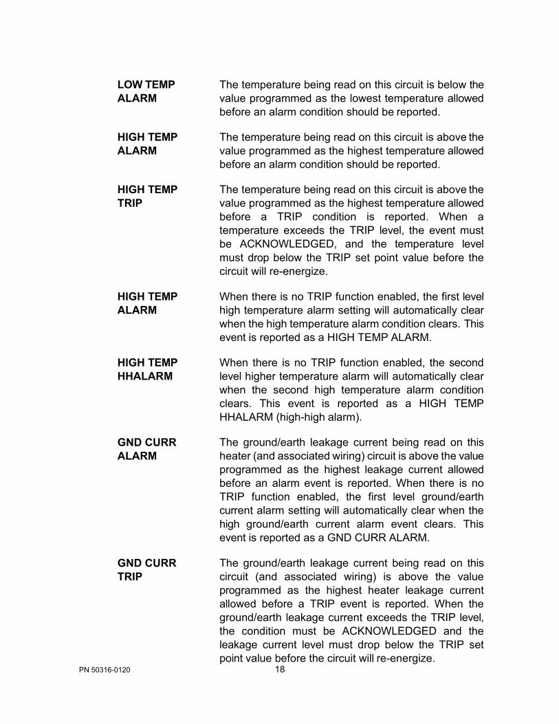
LOW TEMP ALARM
HIGH TEMP ALARM
HIGH TEMP TRIP
HIGH TEMP ALARM
HIGH TEMP HHALARM
GND CURR ALARM
GND CURR TRIP
The temperature being read on this circuit is below the value programmed as the lowest temperature allowed before an alarm condition should be reported.
The temperature being read on this circuit is above the value programmed as the highest temperature allowed before an alarm condition should be reported.
The temperature being read on this circuit is above the value programmed as the highest temperature allowed before a TRIP condition is reported. When a temperature exceeds the TRIP level, the event must be ACKNOWLEDGED, and the temperature level must drop below the TRIP set point value before the circuit will re-energize.
When there is no TRIP function enabled, the first level high temperature alarm setting will automatically clear when the high temperature alarm condition clears. This event is reported as a HIGH TEMP ALARM.
When there is no TRIP function enabled, the second level higher temperature alarm will automatically clear when the second high temperature alarm condition clears. This event is reported as a HIGH TEMP HHALARM (high-high alarm).
The ground/earth leakage current being read on this heater (and associated wiring) circuit is above the value programmed as the highest leakage current allowed before an alarm event is reported. When there is no TRIP function enabled, the first level ground/earth current alarm setting will automatically clear when the high ground/earth current alarm event clears. This event is reported as a GND CURR ALARM.
The ground/earth leakage current being read on this circuit (and associated wiring) is above the value programmed as the highest heater leakage current allowed before a TRIP event is reported. When the ground/earth leakage current exceeds the TRIP level, the condition must be ACKNOWLEDGED and the leakage current level must drop below the TRIP set point value before the circuit will re-energize.

19 PN 50316-0120
GND CURR HHALARM
LOW AMPS ALARM
HIGH AMPS ALARM
HIGH AMPS TRIP
HIGH AMPS HHALARM
CKT FAULT ALARM
GND FAULT ALARM
When there is no TRIP function enabled, the second level higher ground/earth leakage current alarm will automatically clear when the second high ground/earth current alarm event clears. This event is reported as a GND CURR HHALARM (high-high alarm).
The amperage being read on this circuit is below the value programmed as the lowest heater operating current allowed before an alarm condition is reported.
The amperage being read on this circuit is above the value programmed as the highest heater operating current allowed before an alarm condition is reported. When there is no TRIP function enabled, the first level heater operating current alarm setting will automatically clear when the high heater current alarm event clears. This event is reported as a HIGH AMPS ALARM.
The amperage being read on this circuit is above the value programmed as the highest heater operating current allowed before a TRIP condition is reported. When the amperage exceeds the TRIP level, the condition must be ACKNOWLEDGED and the heater operating current level must drop below the TRIP set point value before the circuit will re-energize.
When there is no TRIP function enabled, the second level higher heater current alarm will automatically clear when the second higher heater current alarm event clears. This event is reported as a HIGH AMPS HHALARM (high-high alarm).
A circuit fault condition is reported if during the SELF TEST procedure of energizing each circuit, it is determined that the heater current does not change between the ON and OFF states.
A ground fault condition is reported if during a TRIP- TO-TEST procedure of applying a test leakage current to each circuit, it is determined that the test leakage current is not sensed.

20 PN 50316-0120
INVALID HI TEMP ALRM
INVALID LO TEMP ALRM
This warning message appears when the values that have been programmed into the high temperature alarm and trip settings are in conflict with maintain temperature and control band. Refer to Appendix A for details on the limitations on what high temperature alarm and trip values can be programmed into the TCM18 for a heat tracing circuit.
This warning message appears when the values that have been programmed into the alarm settings for low temperature are in conflict with the maintain temperature. Refer to Appendix A for details on the limitations on what low temperature alarm values can be programmed into the TCM18 for a heat tracing circuit.
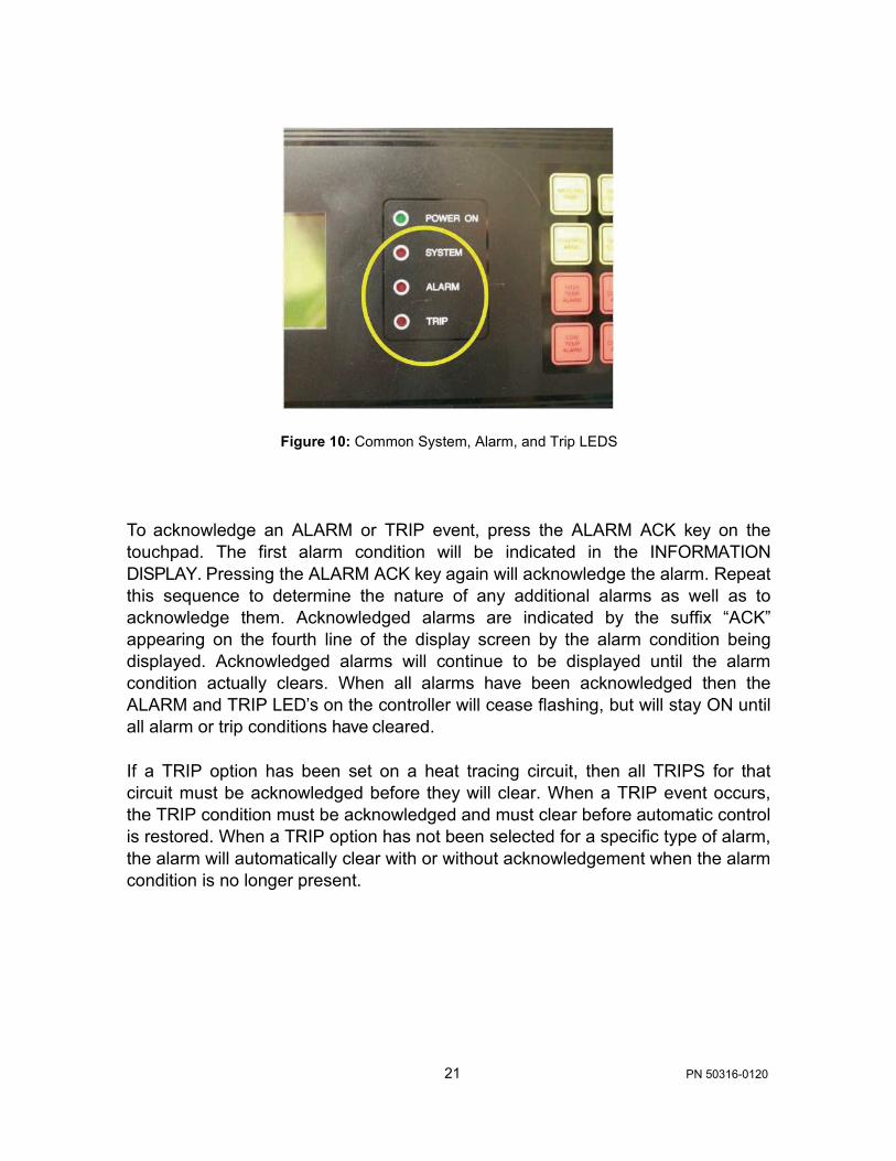
In addition to the individual heat tracing circuit ALARM or TRIP message on the display screen, the “ALARM”, and /or the “TRIP” LED(s) will also begin to flash on the TCM18 front panel as shown in Figure 10. These LED indicators will activate if there are any alarm or trip events recorded on the TCM18 control module. These LEDS will not stop flashing until all conditions have been acknowledged. Once all are acknowledged, the appropriate LED will cease to flash but will remain energized until the condition has actually cleared. These LEDS are also an indication that the three output relays (on the rear of the TCM18 control module) that have been wired to the DCS or other smart monitoring device or to alarm indicating lights or horn are activated.
21 PN 50316-0120
Figure 10: Common System, Alarm, and Trip LEDS To acknowledge an ALARM or TRIP event, press the ALARM ACK key on the touchpad. The first alarm condition will be indicated in the INFORMATION DISPLAY. Pressing the ALARM ACK key again will acknowledge the alarm. Repeat this sequence to determine the nature of any additional alarms as well as to acknowledge them. Acknowledged alarms are indicated by the suffix “ACK” appearing on the fourth line of the display screen by the alarm condition being displayed. Acknowledged alarms will continue to be displayed until the alarm condition actually clears. When all alarms have been acknowledged then the ALARM and TRIP LED’s on the controller will cease flashing, but will stay ON until all alarm or trip conditions have cleared.
If a TRIP option has been set on a heat tracing circuit, then all TRIPS for that circuit must be acknowledged before they will clear. When a TRIP event occurs, the TRIP condition must be acknowledged and must clear before automatic control is restored. When a TRIP option has not been selected for a specific type of alarm, the alarm will automatically clear with or without acknowledgement when the alarm condition is no longer present.

22 PN 50316-0120
6 Accessing Heat Tracing Circuit Information To access information on a specific heat tracing circuit, press the appropriate yellow or red key. Pressing these keys will directly access the information and functions associated with that key. As a typical example, press the MAINTAIN TEMP key as shown in Figure 11.
Figure 11: TCM18 Touch Pad This will result in the display screen response as illustrated below in Figure 12.

23 PN 50316-0120
Figure 12: TCM18 LCD Response
A map of all the information and functions accessible in this manner is summarized in the following list.
Touch Pad Key Information Display for Circuit in View Mode
MAINTAIN TEMP The display screen provides heat tracing circuit number and the temperature control set point.
CONTROL BAND The display screen indicates the heat tracing circuit
number, the temperature control band width, and the programmed control method being employed.
HEATER CURRENT
The display screen indicates the operating heater current and the programmed default power clamp percentage in the event of an RTD fault for the circuit number displayed.
GROUND CURRENT
The display screen indicates the measured ground/earth leakage current for the heat tracing circuit number displayed and the alarm and trip/high- high alarm activation values.
CIRCUIT = 7 MAINTAIN TEMPERATURE MAINT= 49◦C

24 PN 50316-0120
CONFIG 1 The first parameter line on the display screen indicates the TCM18 control instructions (ALL ON, ALL OFF, or BY CKT) for high ground/earth leakage current trip. The second and third lines indicate the control instructions for heater operating current and high temperature trip. An “ALL ON” designation indicates that the heater circuit will trip on a high value and will require the operator to press the ACK key and the condition to clear before the circuit will reset. An “ALL OFF” setting will leave the circuit in an automatic reset mode which allows the alarm to disappear when the condition clears.
Note that the “ALL ON” or “ALL OFF” settings are always global settings for all eighteen circuits on this controller. A “BY CKT” designation means that an individual circuit’s trip functions may be set during the circuit programming process and thus are not global settings.
CONFIG 2 The first parameter line on this display screen indicates
the TCM18 alarm relay configuration options currently selected (options include “ALARM RLY ALL ALARMS” which causes the alarm relay to activate on any alarm or “ALARM RLY TEMP ONLY”) which activates on temperature alarm events only.
The second parameter line on this display screen indicates whether the relays are configured as “ALARM RLY NRM CLOSED” or “ALARM RLY NRM OPEN”. A normally closed relay is of the Form B type and will open on an alarm event. Relays of this convention are quite often used when the alarm/trip contacts are connected to a DCS system or other type of smart monitoring device. An advantage of this alarm relay type is that it also naturally creates an alarm if the controller/system unexpectedly loses power.
A normally open relay is of the Form A type and will close on an alarm event. This relay convention is often used when there is light or some warning device like a horn connected to the alarm relay contacts.

25 PN 50316-0120
The third parameter line on this display screen indicates the amount of time delay (up to 30 minutes) that has been programmed in for a High Temperature Trip event. A value other than “0” for this parameter indicates the operator has chosen to provide a buffer to avoid tripping the heat tracing circuit for a short-term higher temperature exposure /operating event.
Note that these CONFIG settings are always global settings for all eighteen circuits on this controller.
CONFIG 3 The parameter line on this display screen indicates the
programmed time period in hours between automatic heat tracing self test events. The automatic self test turns each heat trace circuit on and then off to deter- mine that there is a current reading difference. The presence of a differential is an indication that the relay is functional and that the circuit breaker has not been tripped. Alternatively, the parameter line may indicate that the self test function is “OFF”.
CONFIG 4 The first parameter line on this display screen indicates
the amount of startup delay in minutes for this TCM18 module. This parameter indicates whether the TCM18 has a built-in delay to “stagger-start” power within a group of TCM18 modules.
The second parameter line on this display screen indicates the length of time allowed for each heat tracing circuit to ramp up to full power during soft start control with power clamping or when in proportional control modes.
Note that these CONFIG settings are always global settings for all eighteen circuits on this controller.
CONFIG 5 The first parameter line on this display screen indicates
the first circuit number to be designated for this TCM18. The TCM18 allows the first circuit number to be programmed from 1 to 82. This is useful where multiple TCM18 controllers are present in a common panel.

26 PN 50316-0120
The second parameter line on this display screen indicates the temperature units to be displayed on the screen. Units to be displayed are either in degrees Fahrenheit or degrees Celsius.
Note that these CONFIG settings are always global settings for all eighteen circuits on this controller.
HEATER ENABLE
Indicates the heat tracing circuit number displayed, the heater circuit status (enabled, forced (on or off), disabled (off), or tripped (off)), and the RTD setup (single RTD pipe sense, dual RTD pipe sense, single RTD ambient sense, dual RTD ambient sense, or single RTD on pipe or heater and single RTD ambient sensed.
DATA HWY 1 Indicates the data highway address for this TCM18
module, the programmed communication protocol, the message type, and the communication Baud rate.
HIGH TEMP ALARM
Indicates the heat tracing circuit number displayed and the high temperature alarm and trip set points. If no trip is set, the first and second level high temperature alarm set points will be displayed.
LOW TEMP ALARM
Indicates the heat tracing circuit number displayed and the low temperature alarm set points.
HIGH CURRENT ALARM
Indicates the heat tracing circuit number displayed and the high heater operating current alarm and trip set points. If no trip is set, the first and second level heater current alarm set points will be displayed.
LOW CURRENT ALARM
Indicates the heat tracing circuit number displayed and the low heater operating current alarm set points.
(1, 2, 3, 4, 5) Multiple presses of the applicable key or pressing ENTER on the last screen entry will result in subsequent display screens appearing.

27 PN 50316-0120
7 Programming the TCM18 The TCM18 has an electronic password security provision. To access the programming mode, enter the 4-digit numerical security code. If no code has been entered, press the PROG key followed by the ALARM ACK key and subsequently followed by the PROG key. Next, successively select a numerical code using the UP and DOWN arrow keys along with the ENTER key. An entry of 0000 will deactivate the security code feature. Note that once a security code has been entered, the user has unlimited access as long as activity is present. A period of inactivity of 30 minutes or more will result in programming access being denied. At this point, re-entry of the security code will be required. If the security code is forgotten at some future date, enter a value of 1954 (during the first 5 minutes after power is applied to the TCM18) as the security code, then a new code may be entered by pressing the ALARM ACK key and subsequently followed by the PROG key.
To program circuit control settings or control parameters, multiple keys in sequence will need to be pressed. For example, to change the settings associated with the MAINTAIN TEMP key, first press the green PROG key.

28 PN 50316-0120
PROGRAM MODE ENABLED SELECT FUNCTION KEY
Figure 13: TCM18 PROG Key The Display now reads as shown below:
Figure 14: Program Mode Enabled Press the MAINTAIN TEMP key.

29 PN 50316-0120
PROGRAM CIRCUIT = 7I MAINTAIN TEMPERATURE MAINT= 49◦C
Figure 15: MAINTAIN TEMP Key
The Display now reads as shown below with the flashing cursor I representing the active data entry field:
Figure 16: Programming Maintain Temperature Pressing the green UP or DOWN Arrow programming keys followed by the green ENTER key allows the selection of the heat tracing circuit to program.
30 PN 50316-0120
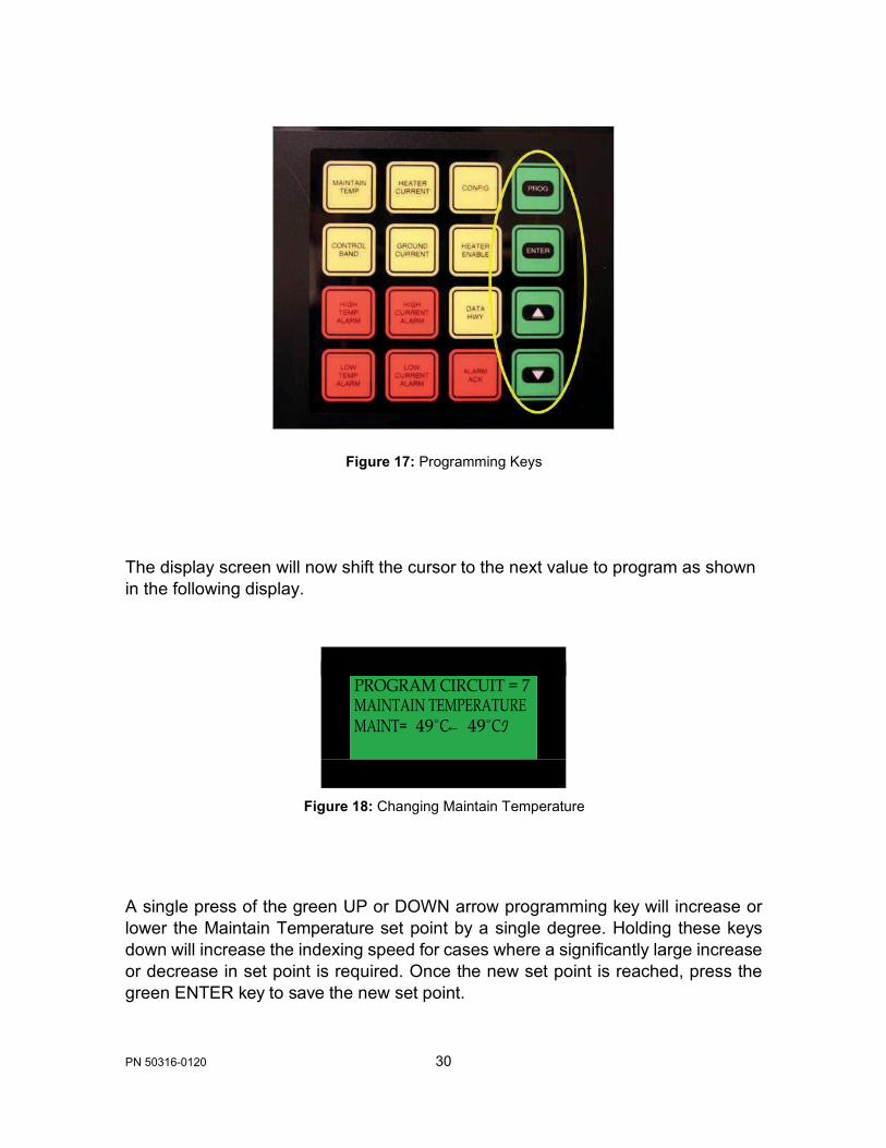
PROGRAM CIRCUIT = 7 MAINTAIN TEMPERATURE MAINT= 49◦C← 49◦CI
Figure 17: Programming Keys The display screen will now shift the cursor to the next value to program as shown in the following display.
Figure 18: Changing Maintain Temperature A single press of the green UP or DOWN arrow programming key will increase or lower the Maintain Temperature set point by a single degree. Holding these keys down will increase the indexing speed for cases where a significantly large increase or decrease in set point is required. Once the new set point is reached, press the green ENTER key to save the new set point.

31 PN 50316-0120
PROGRAM CIRCUIT = 7I MAINTAIN TEMPERATURE MAINT= 52◦C
Figure 19: The ENTER Key The DISPLAY screen now appears as shown in Figure 20.
Figure 20: Selecting a New Circuit Number
At this point, pressing the green UP or DOWN arrow key will select the next heat tracing circuit to program. Alternatively, press the green PROG key to exit and return to SCAN MODE. However, if for some reason this is not done, the screen will automatically return to SCAN mode operation after a short pause.

32 PN 50316-0120
When completed with this or any programming activity, always press the green PROG key to exit and return to SCAN MODE.
Figure 21: The PROG Key A map of all the programmable parameters accessible in this or a similar manner is summarized in the following list.
TIP: In many cases, the programmed value can be the same for a majority of heat tracing circuits. Note that when sequencing through the circuit numbers, there is an ALL option. This allows the programming of the same set point for all circuits on this particular TCM18 module and permits only entering the set point once. When selecting the ALL option, the values last programmed for ALL will initially appear as a starting point for any value changes.

33 PN 50316-0120
Touch Pad Key Sequence
Programmable Circuit Functions
PROG plus MAINTAIN TEMP
This display screen indicates the heat tracing circuit number selected. Using the UP or DOWN arrow, select the desired circuit number or ALL and press ENTER. The flashing cursor now moves to the temperature control set point (maintenance temperature). Press the UP or DOWN keys to change the present setting. Press the ENTER key to accept the new value.
Temperature control setting range limits are -200◦F to 1112◦F (-129◦C to 600◦C). Note that the temperature control setting may not be set lower than the low temperature alarm value nor higher than the high temperature alarm minus the control band value.
Press the PROG key at any point to exit from this sequence. If left in the program mode, the TCM18 will after a short wait automatically return to the SCAN mode.
PROG plus CONTROL BAND
This display screen allows the programming of the temperature control band and control method parameters for each of the eighteen circuits individually or for all circuits (in the case the value is identical). Control band width setting range is 1 to 320 ◦F or 1 to 178 ◦C. Note also that the control band cannot be set at a value greater than the high temperature alarm value minus the maintain temperature. The selectable options for control methods are ON/OFF, SOFT START, or PROPORTIONAL. Noting the location of the flashing cursor, press the UP or DOWN keys to change the present settings. Press the ENTER key to accept the new values.

34 PN 50316-0120
The ON/OFF mode may be used with either mechanical relay or solid state relay heater current switching relays. The SOFT START and PROPORTIONAL control methods are only used with the zero crossing solid state current switching relay configurations as these control modes pulse power during start-up, power clamping, and also when employing a full proportional control algorithm.
Press the PROG key at any point to exit from this sequence. If left in the program mode, the TCM18 will after a short wait automatically return to the scan mode.
PROG plus HEATER CURRENT
This display screen allows the programming of the default power clamp percentage in the event of an RTD fault for each of the eighteen circuits individually or for all circuits (in the case the value is identical). The setting range limits for this parameter is 20 to 100%. Noting the location of the flashing cursor, press the UP or DOWN keys to change the present settings. Press the ENTER key to accept the new values.
Press the PROG key at any point to exit from this sequence. If left in the program mode, the TCM18 will after a short wait automatically return to the SCAN mode.
PROG plus GROUND CURRENT1
This display screen allows the programming of the ground/earth leakage current value at which to trigger an alarm or trip event for each of the eighteen circuits individually or for all circuits (in the case the value is identical). The setting range limits for this parameter is 15 to 225 mA.
Press the PROG key at any point to exit for this sequence. If left in the program mode, the TCM18 will after a short wait automatically return to the SCAN mode.

35 PN 50316-0120
PROG plus CONFIG1
This first display screen allows the programming of the TCM18 control instructions (ALL ON, ALL OFF, or BY CKT) for high ground/earth leakage current (GND CUR TRIP), heater operating current (HTR CUR TRIP) and high temperature trip (HI TEMP TRIP). Noting the flashing cursor location, press the UP or DOWN arrow keys to select a new option and press ENTER to accept. The flashing cursor now moves to the next line where the process may be repeated.
An “ALL ON” designation indicates that all heater circuits will trip on the high trip value and will require the operator to press the ACK key and the condition to clear before the circuit will reset. An “ALL OFF” setting will leave all of the circuits in an automatic reset mode which results in the heater automatically resetting when the condition clears.
When the configuration set up is “BY CKT”, these options will be prompted and can be programmed on a circuit by circuit basis during individual programming of the alarm/trip set point values.
Note that the “ALL ON” or “ALL OFF” settings are global and if selected will overwrite any previous “BY CKT” settings employed.
Press the PROG key at any point to exit for this sequence. If left in the program mode, the TCM18 will after a short wait automatically return to the SCAN mode.

36 PN 50316-0120
PROG plus CONFIG2
Having completed selections on the first display screen, the flashing cursor will move to the second display screen. This second display screen allows the programming of the TCM18 alarm relay configuration options (“ALARM RLY ALL ALARMS” or “ALARM RLY TEMP ONLY”). This allows the user to either activate the alarm relay on any alarm event occurring on this TCM18 or only when a temperature alarm occurs on the TCM18. The resulting alarm relay action allows the operator to provide a visual or sound indication or notify the DCS (depending how the panel is equipped) of an alarm event In addition, the ALARM LED on the front panel always activates during any alarm event. Press the UP or DOWN arrow keys to select a new option and press ENTER to accept. The flashing cursor now moves to the next line where the process may be repeated.
This second display screen also allows the programming of the TCM18 to designate the relay alarm action as “ALARM RLY NRM CLOSED” or “ALARM RLY NRM OPEN”. A normally closed relay is of the Form B type and will open on an alarm event. Relays of this convention are quite often used when contacts are connected to a DCS system or other type of smart monitoring device. An advantage of this alarm relay type is that it also naturally creates an alarm if the controller/system unexpectedly loses power. A normally open relay is of the Form A type and will close on an alarm event. This relay convention is often used when there is light or some warning device like a horn connected to the alarm relay contacts.
Press the UP or DOWN arrow keys to select a new option and press ENTER to accept.

37 PN 50316-0120
The flashing cursor now moves to the next line which allows the operator of the TCM18 to program a certain amount of time delay for a High Temperature Trip event. A value other than 0 for this parameter indicates the operator has chosen to filter out and minimize tripping the heat tracing circuit for a short-term higher temperature exposure operating event. Press the UP or DOWN arrow keys to enter a new value and press ENTER to accept.
Note that all of these values are global and apply to all eighteen circuits on this TCM18 controller.
Press the PROG key at any point to exit for this sequence. If left in the program mode, the TCM18 will after a short wait, automatically return to the SCAN mode.
PROG plus CONFIG3
The flashing cursor now moves to a third display screen. This third display screen allows the operator of the TCM18 to program the time period in hours between automatic heat tracing self test events. A self test will check for functionality of the relays (by turning each heat tracing circuit relay on and then off and making sure that there is a difference in the heater current read). Press the UP or DOWN arrow keys to enter a new value and press ENTER to accept. Pressing the ENTER key when “RUN” is selected immediately invokes a SELF TEST. This setting does not change the programmed the time period. Selecting the “OFF” option deactivates the self test function.
PROG plus CONFIG4
The flashing cursor now moves to the next display screen which allows the operator of the TCM18 to program the amount of start-up delay in minutes for this TCM18 module. This option permits a staggered start-up for a grouping of TCM18 modules. Press the UP or DOWN arrow keys to enter a new value and press ENTER to accept.

38 PN 50316-0120
The flashing cursor now moves to the next line which allows the operator of the TCM18 to program the amount of time in minutes (soft start time) over which the TCM18 will ramp up the power from 20% to 100% power clamp level. This option applies to SOFT START and PROPORTIONAL control modes. Press the UP or DOWN arrow keys to enter a new value and press ENTER to accept.
PROG plus CONFIG5
The flashing cursor now moves to the next display screen which allows the operator to set the beginning circuit number to a value from 1 to 82 on this particular TCM18 control and monitoring module. Press the UP or DOWN arrow keys to enter a new value and press ENTER to accept.
The flashing cursor now moves to the next line which allows the operator of the TCM18 to program the preferred units (◦F or ◦C) in which the temperatures measured by the RTD(s) will be displayed.
Note that all of these values are global and apply to all eighteen circuits on this TCM18 controller.
Press the PROG key at any point to exit for this sequence. If left in the program mode, the TCM18 will after a short wait, automatically return to the SCAN mode.
PROG plus HEATER ENABLE
This display screen allows the programming of the heater operating status for each of the eighteen circuits individually or for all circuits (in the case the value is identical). The heater operating status selectable options are:

39 PN 50316-0120
1. ENABLED (selected for the normal control mode)
2. FORCED ON (typically selected to turn the heater on for diagnostic purposes). This setting will automatically revert back to the “ENABLED” status if a high or low temperature alarm event occurs and the ALARM ACK is pressed. As exceptions, when an auxiliary Forced Off switch is included and activated in the panel with the TCM18, all circuits will remain OFF during a Low Temperature alarm event. When an auxiliary Forced On switch is provided and activated with the TCM18, all circuits will alarm when the high temperature alarm set point is reached and will begin controlling at this value until the condition is corrected or the Forced On switch is turned off.
3. SPARE (selected where spare circuits are included in set-up and operator does not want to see spare circuit information during the SCAN sequencing process).
4. DISABLED (selected to take a circuit out of operation).
Note when Ambient Proportional Control is selected the labels “AMB” become “APC”
Also included in this programming sequence is the setting of the heater and RTD coordination. The selectable options are:
1. 1 PIPE (single pipe sensing RTD controlling one heater circuit)
2. 2 PIPE (dual pipe sensing RTD’s controlling a single heater circuit with control off the lowest reading and alarm/trip off the highest reading)
3. 1 AMB (ambient sensing based on RTD1 on one or more of the heat tracing circuits). Refer to Part 8 for additional detail.
40 PN 50316-0120
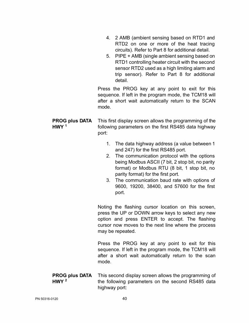
4. 2 AMB (ambient sensing based on RTD1 and RTD2 on one or more of the heat tracing circuits). Refer to Part 8 for additional detail.
5. PIPE + AMB (single ambient sensing based on RTD1 controlling heater circuit with the second sensor RTD2 used as a high limiting alarm and trip sensor). Refer to Part 8 for additional detail.
Press the PROG key at any point to exit for this sequence. If left in the program mode, the TCM18 will after a short wait automatically return to the SCAN mode.
PROG plus DATA HWY 1
This first display screen allows the programming of the following parameters on the first RS485 data highway port:
1. The data highway address (a value between 1 and 247) for the first RS485 port.
2. The communication protocol with the options being Modbus ASCII (7 bit, 2 stop bit, no parity format) or Modbus RTU (8 bit, 1 stop bit, no parity format) for the first port.
3. The communication baud rate with options of 9600, 19200, 38400, and 57600 for the first port.
Noting the flashing cursor location on this screen, press the UP or DOWN arrow keys to select any new option and press ENTER to accept. The flashing cursor now moves to the next line where the process may be repeated.
Press the PROG key at any point to exit for this sequence. If left in the program mode, the TCM18 will after a short wait automatically return to the scan mode.
PROG plus DATA HWY 2
This second display screen allows the programming of the following parameters on the second RS485 data highway port:

41 PN 50316-0120
1. The data highway address (a value between 1 and 247) for the second RS485 port.
2. The communication protocol with the options being Modbus ASCII (7 bit, 2 stop bit, no parity format) or Modbus RTU (8 bit, 1 stop bit, no parity format) for the second port.
3. The communication baud rate with options of 9600, 19200, 38400, and 57600 for the second port.
Noting the flashing cursor location on this screen, press the UP or DOWN arrow keys to select any new option and press ENTER to accept. The flashing cursor now moves to the next line where the process may be repeated.
Press the PROG key at any point to exit for this sequence. If left in the program mode, the TCM18 will after a short wait automatically return to the scan mode.
PROG plus HIGH TEMP ALARM 1
This first display screen indicates the heat tracing circuit number selected. Using the UP or DOWN arrow select the desired circuit number or ALL and press ENTER. The flashing cursor moves to the high temperature alarm “TRIP” value and allows the programming of the trip set points by using the UP or DOWN key. Note that if NO TRIP has been selected under the CONFIG key, this value will be renamed the HHALARM (for high-high alarm) from TRIP. Press ENTER to accept the new value. The flashing cursor now moves to the “ALARM” value and allows the programming of the alarm set point by using the UP or DOWN key. Press ENTER to accept the new value.
Note that if the operator has selected to choose trip preferences by circuit under the CONFIG key, an additional screen display will prompt for the operator to indicate a “Y” to confirm that TRIP functionality is desired on the displayed circuit.

42 PN 50316-0120
Press the PROG key at any point to exit from this sequence. If left in the program mode, the TCM18 will after a short wait automatically return to the SCAN mode.
PROG plus HIGH TEMP ALARM 2
A new display screen appears which indicates the HIGH TEMP SEEN value, which is the highest temperature that has been measured on the designated RTD(s). The flashing cursor moves to the RESET and allows the operate to erase the restored historical value on the designated RTD(s) by selecting the “N” for a no answer or by using the UP or DOWN arrow keys to change to “Y” for a yes answer.
Where the ALL circuits option has been selected in this programming sequence, the display screen will not show the present highest temperature seen values of all heat tracing circuits on this TCM18 but will reset ALL of the Highest Temperature Seen values to the present reading values without further review.
In the unlikely event of an RTD fault where the present reading is out of normal range, the TCM18 will set the new Highest Temperature Seen to an extreme low value such that as soon as the RTD is repaired, the new highest temperature seen will replace the abnormal value.
Press the PROG key at any point to exit from this sequence. If left in the program mode, the TCM18 will after a short wait automatically return to the SCAN mode.
PROG plus HIGH TEMP ALARM 3
If the operator has selected to choose trip preferences by circuit under the CONFIG key, an additional third screen display will prompt for the operator to indicate a “Y” to confirm that TRIP functionality is desired for this parameter on the displayed circuit.

43 PN 50316-0120
PROG plus LOW TEMP ALARM 1
This first display screen indicates the heat tracing circuit number selected. Using the UP or DOWN arrow select the desired circuit number or ALL and press ENTER. The flashing cursor moves to the present low temperature alarm value and allows the programming of the alarm set points by using the UP or DOWN key. Press the ENTER key to accept the new values.
Low temperature alarm setting range limits are generally -200◦F to 1112◦F (-129◦C to 600◦C). However, the low temperature alarm setting also cannot be set higher than the temperature control set point (maintain temperature) value.
Press the PROG key at any point to exit from this sequence. If left in the program mode, the TCM18 will after a short wait automatically return to the SCAN mode.
PROG plus LOW TEMP ALARM 2
A new display screen appears which indicates the LOW TEMP SEEN value which is the lowest temperature that has been measured on the designated RTD(s). The flashing cursor moves to the RESET and allows the operate to erase the restored historical value on the designated RTD(s) by selecting the “N” for a no answer or by using the UP or DOWN arrow keys to change to “Y” for a yes answer.
Where the “ALL” circuits option has been selected in this programming sequence, the display screen will not show the present lowest temperature seen values of all heat tracing circuits on this TCM18 but will reset ALL of the Lowest Temperature Seen values to the present reading values without further review.
In the unlikely event of an RTD fault where the present reading is out of normal range, the TCM18 will set the new Lowest Temperature Seen to an extreme high value such that as soon as the RTD is repaired, the new lowest temperature seen will replace the abnormal value.

44 PN 50316-0120
Press the PROG key at any point to exit from this sequence. If left in the program mode, the TCM18 will after a short wait, automatically return to the SCAN mode.
PROG plus HIGH CURRENT ALARM 1
This display screen first indicates the heat tracing circuit number selected. Using the UP or DOWN arrow, select the desired circuit number or ALL and press ENTER. The flashing cursor moves to the present high current TRIP value and allows the programming of a new TRIP value by using the UP or DOWN key. Press the ENTER key to accept the new value.
The flashing cursor then moves to the ALARM value and allows the programming of a new ALARM value by using the UP or DOWN key. Press the ENTER key to accept the new values.
Note that the high current ALARM value is always lower or equal to the TRIP value and is designed to serve as an initial warning level.
Note that if no TRIP function has set under CONFIG, the TRIP value is renamed as HHALARM (high - high current alarm).
Press the PROG key at any point to exit from this sequence. If left in the program mode, the TCM18 will after a short wait automatically return to the SCAN mode.
PROG plus HIGH CURRENT ALARM 2
If the operator has selected to choose trip preferences by circuit under the CONFIG key, an additional second screen display will prompt for the operator to indicate a “Y” to confirm that TRIP functionality is desired for this parameter on the displayed circuit.

45 PN 50316-0120
PROG plus LOW CURRENT ALARM
This display screen first indicates the heat tracing circuit number selected. Using the UP or DOWN arrow, select the desired circuit number or ALL and press ENTER. The flashing cursor moves to the present low current ALARM value and allows the programming of a new ALARM value by using the UP or DOWN key. Press the ENTER key to accept the new value.
Press the PROG key at any point to exit from this sequence. If left in the program mode, the TCM18 will after a short wait automatically return to the SCAN mode.
(1, 2, 3, 4, 5) Multiple presses of the applicable key or pressing ENTER on the last screen entry will result in subsequent display screens appearing.
46 PN 50316-0120
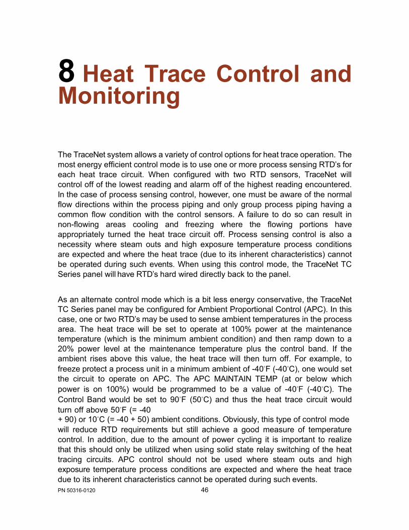
8 Heat Trace Control and Monitoring The TraceNet system allows a variety of control options for heat trace operation. The most energy efficient control mode is to use one or more process sensing RTD’s for each heat trace circuit. When configured with two RTD sensors, TraceNet will control off of the lowest reading and alarm off of the highest reading encountered. In the case of process sensing control, however, one must be aware of the normal flow directions within the process piping and only group process piping having a common flow condition with the control sensors. A failure to do so can result in non-flowing areas cooling and freezing where the flowing portions have appropriately turned the heat trace circuit off. Process sensing control is also a necessity where steam outs and high exposure temperature process conditions are expected and where the heat trace (due to its inherent characteristics) cannot be operated during such events. When using this control mode, the TraceNet TC Series panel will have RTD’s hard wired directly back to the panel.
As an alternate control mode which is a bit less energy conservative, the TraceNet TC Series panel may be configured for Ambient Proportional Control (APC). In this case, one or two RTD’s may be used to sense ambient temperatures in the process area. The heat trace will be set to operate at 100% power at the maintenance temperature (which is the minimum ambient condition) and then ramp down to a 20% power level at the maintenance temperature plus the control band. If the ambient rises above this value, the heat trace will then turn off. For example, to freeze protect a process unit in a minimum ambient of -40◦F (-40◦C), one would set the circuit to operate on APC. The APC MAINTAIN TEMP (at or below which power is on 100%) would be programmed to be a value of -40◦F (-40◦C). The Control Band would be set to 90◦F (50◦C) and thus the heat trace circuit would turn off above 50◦F (= -40 + 90) or 10◦C (= -40 + 50) ambient conditions. Obviously, this type of control mode will reduce RTD requirements but still achieve a good measure of temperature control. In addition, due to the amount of power cycling it is important to realize that this should only be utilized when using solid state relay switching of the heat tracing circuits. APC control should not be used where steam outs and high exposure temperature process conditions are expected and where the heat trace due to its inherent characteristics cannot be operated during such events.

47 PN 50316-0120
As a third control mode option, which is a less energy conservative approach, the TraceNet TC Series panel may be configured for Ambient ON/OFF Control. In this case, one or two RTD’s may be used to sense ambient temperatures in the process area. The heat trace will be set to operate at 100% power whenever the ambient temperature drops below the maintenance temperature which is typically set at 50◦F (10◦C). If the ambient rises above this value, the heat trace will turn off. Obviously, this type of control mode will also reduce RTD requirements. In this case, there will naturally be some temperature overshoot expected in the process as the ambient approaches the turn off point. In this case, mechanical relay switching of the heat tracing circuits may be used. Ambient Sensing ON/OFF control should not be used where steam outs and high exposure temperature process conditions are expected and where the heat trace due to its inherent characteristics cannot be operated during such events.

48 PN 50316-0120
CIRCUIT = 12 HEATER SETUP HEATER = ENABLED RTD SETUP =1 PIPE
9 The TCM18 in Process Sensing Applications The TCM18 control module can be configured for process (pipe, vessel, or equipment surface) sensing with either a single RTD input (RTD 1 ribbon cable connections) for each heat tracing circuit or alternately it can be configured for dual RTD inputs (using both RTD1 and RTD2 ribbon cable connections in a TC Series panel where provision has been made to wire a second RTD for each heat tracing circuit). Further, it is possible to have some of each configuration within a panel as long as the RTD wiring provisions have been done in the panel. To check on the RTD configuration that exists in the TCM18, press the HEATER ENABLE key. The typical display screen (in the case of a single RTD input sensor) will appear as follows.
Figure 22: RTD Setup To change to dual RTD inputs on this circuit (having cleared security by entering the appropriate security code), press the green PROG key followed by the yellow HEATER ENABLE key. The following display screen will appear with the flashing cursor next to the circuit number.

49 PN 50316-0120
CIRCUIT = 12 HEATER SETUP HEATER = ENABLED I RTD SETUP =1 PIPE
Figure 23: Select Circuit Number
At this point, the other options are to move to another CIRCUIT or to the ALL option through the use of the UP and DOWN arrow keys. In this case, select the green ENTER key to select this circuit. The flashing cursor now moves to the HEATER ENABLED line as seen below.
Figure 24: Heater Setup Press the ENTER key in order to save the current setting of HEATER ENABLED. The flashing cursor now moves to the RTD SETUP line. Press the green UP arrow key and press the green ENTER key to set in the option of 2 PIPE.
CIRCUIT = 12I HEATER SETUP HEATER = ENABLED RTD SETUP =1 PIPE

50 PN 50316-0120
PIPE I
TIP: If most of the circuits on a TCM18 have a single RTD input, use the program ALL feature to first configure each circuit as a “1 PIPE” control convention. Next select the circuits where dual RTDs are to be used and program them individually using the 2-PIPE convention.
Figure 25: Select RTD Setup
With the circuit 12 now set up as a 2 RTD convention and with both of the RTDs installed in the appropriate RTB6 modules and the two ribbon cables connected into the back of the TCM18 into the RTD1/RC2 and RTD2/RC2 slots, the new set up is complete. With a dual RTD setup, the control RTD will be the sensor which is read- ing the lowest temperature. It will control the pipe, vessel or equipment within the range of the MAINTAIN TEMP and the MAINTAIN TEMP plus the CONTROL BAND. The second higher reading RTD will be used to turn off the heat tracing circuit in the event of that sensor reading being a value in excess of the HIGH TEMP ALARM value.
CIRCUIT = 12 HEATER SETUP HEATER = ENABLED RTD SETUP =2

51 PN 50316-0120
10 The TCM18 in Ambient Sensing Applications The TCM18 has a specially designed ambient sensing control algorithm to facilitate the ultimate in flexibility as to the number of ambient sensors and their various location placements within a TCM18 control and monitoring module. Details regarding these rules may be found in Appendix B.
While these rules allow for a great deal of flexibility in location of the ambient sensing RTD’s within a TCM18, it is traditional when using ambient sensing RTD’s to place the main and backup ambient sensing RTD’s in the RTD1 and RTD2 locations of the first heat tracing circuit. Any other circuits that are programmed as ambient sensing will then control based on the sensor readings in the first heat tracing circuit on this TCM18. The following list outlines the programming steps required for set up.
Key Press Operation Description
PROG plus HEATER ENABLE
This sequence allows the programmer to select the number of ambient RTD sensors to be used. The flashing cursor first requests the selection of the circuit number to select ambient sensing for. Press the UP or DOWN arrow key to select Circuit 1. Press the ENTER key. The cursor moves to the Heater Status line. Use the UP or DOWN key to ENABLE the heater on this circuit. Press the ENTER key. The cursor then moves to the RTD SETUP line. Use the UP or DOWN key to select either 1 AMB or 2 AMB (1 APC or 2 APC when Ambient Proportional Control is set up) depending on whether it is desired to control with one main RTD sensor or have an additional backup ambient RTD sensor. Press the ENTER key to select ambient sensing on Circuit 1.

52 PN 50316-0120
PROG plus CONTROL BAND
This sequence allows the programmer to select the type of ambient control desired on Circuit 1. The flashing cursor again requests the selection of the circuit number. Press the UP or DOWN arrow key to select Circuit 1. Press the ENTER key. The cursor moves to the CONTROL BAND line. Use the UP or DOWN key to select the Heater On to Heater Off differential (when using an ON-OFF or SOFT START, with power clamping, control mode). When using a proportional control mode, the Heater On to Heater Off differential determines the 100% power to 20% and OFF power differential. Note that the TCM18 allows a wide band control differential of as high as 320◦F or 177◦C to be entered. After selecting the differential, press the ENTER key. The cursor then moves to the Control Type line. Use the UP or DOWN key to select from the options of ON/OFF, SOFT START, or PROPORTIONAL. Having selected the desired option, press the ENTER key. Note that ON-OFF control is a valid option for both panels with solid state relay power switching and mechanical relay power switching. The selection of SOFT START and PROPORTIONAL can only be used with solid state power switching relays.
PROG plus HEATER ENABLE and PROG plus CONTROL BAND
Repeat the first two steps in this list as needed to add additional pipe sensed and ambient sensed RTD assignments to the remainder of the TCM18 circuits.

53 PN 50316-0120
11 The TCM18 Data Highway Communications The TCM18 is provided with two RS485 communications ports. These ports allow for communication through Modbus ASCII or RTU protocols to a PC workstation and/or to the facility distributed control system (DCS). The TCM18 is also provided with an auxiliary 24 Vdc power source which can power optional communication converter modules which will accept the TCM18 data highway information and convert it to an alternate data stream protocol. Through these communication links, most of the operating parameters which are programmable at the module can be accessible at the central PC workstation, DCS system console, or other mobile interface devices.
For communications linking information between the TCM18 and a PC workstation, refer to the TraceView™ Network Explorer Operating Guide.
For communications linking information between the TCM18 and a DCS or other network modules, refer to the TCM18 DCS Communication Guide, 50310.

54 PN 50316-0120
12 System Start-Up
All heat trace circuits should be properly terminated and meggered prior to energizing the heat trace power distribution and control panels. In addition, all pipes should be insulated and weather sealed to achieve the expected heat up and temperature maintenance performance of the system.
Troubleshooting Tips When starting up a newly installed heat trace and control system, it is not uncommon to encounter numerous alarm and trip events. Data entry errors, unanticipated temperature overshoots due to system inertia or too tight control band settings, and incomplete installation details are just a few of the many contributing factors to this result. A table of Troubleshooting Tips is provided in Appendix A to assist during start-up.

55 PN 50316-0120
13 Maintenance
Preventative maintenance consists of inspection, testing, checking connections, and general cleaning of equipment at scheduled intervals. The maintenance recommendations that follow are intended to support and in some cases “add to” those procedures detailed in the facility’s Planned Maintenance System (PMS). In case of conflicts, contact the project engineer for resolution. When carrying out the scheduled maintenance program, the following safety precautions should be observed.
Safety Precautions
The heat tracing can be powered by the project specified nominal voltages ranging from 100 to 600 Vac. It is important that only authorized trained personnel conduct these maintenance and service activities. Before conducting any maintenance or service procedure, exercise required lockout and tag out procedures at the appropriate circuit breakers. Additionally, do additional testing within the control panel to ensure that the specific heat tracing and control circuit of interest is fully de-energized and the equipment is grounded.
If it becomes necessary to service or test live equipment, the following instructions must be followed:
• Use one hand when servicing the equipment. Accidental death or severe injury may occur especially if a current path is created through the body from one hand to the other.
• First, de-energize the equipment. To de-energize any capacitors connected into the circuits, temporarily ground the terminals where work is to be done.
• Connect the multi-meter/instrument to the terminals of interest using a range higher than the expected. Make sure that you are not grounded whenever a need arises to adjust equipment or test circuit operation. Verify that all test equipment used is properly maintained and safe for the intended use.
• Without touching the multi-meter/instrument energize the equipment and read the values indicated on the multi-meter/instrument.
• Remove the test leads after de-energizing the circuit of interest.

56 PN 50316-0120
Maintenance Schedule Recommendation The service schedule is somewhat dependent on the “in service” hours. As a general rule, however, it is recommended that the heat tracing control and monitoring panel be serviced on a twelve-month basis to start. The schedule may be adjusted depending on the operating history of the panel and as the historical maintenance records dictate. The recommended typical list of tools and test equipment follows:
Tools Comment
Multimeter Calibrated and in Safe Working Order Flashlight
Vacuum Cleaner Nonmetallic Nozzle Screw Drivers Standard as Well as Torque Type Wrenches Standard as Well as Torque Type Fuse Extractor
Stiff Bristle Wire Brush
Infrared Camera Helpful in Checking Out Soundness of Connections
57 PN 50316-0120
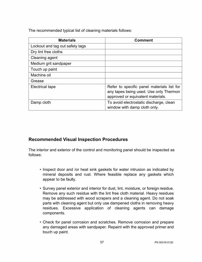
The recommended typical list of cleaning materials follows:
Materials Comment Lockout and tag out safety tags
Dry lint free cloths
Cleaning agent
Medium grit sandpaper
Touch up paint
Machine oil
Grease
Electrical tape Refer to specific panel materials list for any tapes being used. Use only Thermon approved or equivalent materials.
Damp cloth To avoid electrostatic discharge, clean window with damp cloth only.
Recommended Visual Inspection Procedures The interior and exterior of the control and monitoring panel should be inspected as follows:
• Inspect door and /or heat sink gaskets for water intrusion as indicated by mineral deposits and rust. Where feasible replace any gaskets which appear to be faulty.
• Survey panel exterior and interior for dust, lint, moisture, or foreign residue. Remove any such residue with the lint free cloth material. Heavy residues may be addressed with wood scrapers and a cleaning agent. Do not soak parts with cleaning agent but only use dampened cloths in removing heavy residues. Excessive application of cleaning agents can damage components.
• Check for panel corrosion and scratches. Remove corrosion and prepare any damaged areas with sandpaper. Repaint with the approved primer and touch up paint.

58 PN 50316-0120
• Check door hinges, latches, and other moving parts for proper operation. Use machine oil to lubricate the moving parts and restore proper operation where necessary.
• Check for mechanical damage to any windows as well as check the window seals. Repair or replace damaged materials.
In all cases where equipment damage is observed, a root cause analysis should be initiated to determine any future corrective action needed to prevent a recurrence.
Wiring and Connections Survey The wiring and connections survey recommended is as follows:
• If the servicing of removable electrical connectors is to be conducted, then
make certain the area is free of explosive atmospheres.
• If equipment is available, an infrared scan of the interior of the panel cabinet and associated wiring (while in operation) is recommended. Any unusually high temperatures at connections are usually evidence of poor connections. Tighten connections, repair with new terminations, and/or replace any components which have been exposed to long term overheating. All terminal block connections should be tightened using a torque indicating screwdriver to the levels indicated in Table 1 and project installation drawings.
• Check for corrosion at electrical connections and terminations. Where corrosion of electrical terminals is observed, this may be additional evidence of loose connections and excessive heat. A part replacement may be necessary.
• Inspect wiring for abrasion wear, mechanical damage, and thermal overexposure. Repair or replace any damaged or defective wiring.
In all cases where equipment damage is observed, a root cause analysis should be initiated to determine any future corrective action needed to prevent a recurrence.
Control System Operation Check The TCM18 controller screen is an ideal resource in facilitating operation checks of the control system. To begin this program, energize the panel and the appropriate heat trace circuits for a minimum of 24 hours or until all circuits are cycling within their appropriate control band. A typical list of operational maintenance checks are

59 PN 50316-0120
given in the following table.
Tests Description Perform Self Test The Self Test function (accessed by
pressing the CONFIG key) checks circuit breaker and output relay functionality.
Perform SCAN Mode Review Operator should do a visual check for out of range temperatures and low or high heater and ground/earth leakage current in the heat tracing circuit(s). No alarms shall be present on any circuits in the fourth line of the display screen.
Perform Simulated Ground / Earth Leakage Trip Exercise
The TCM18 can simulate a high ground/earth leakage (accessed by pressing the CONFIG key) and manually cause a trip to occur. This allows the operator to verify that the ground/earth leakage function is operable.

60 PN 50316-0120
14 Notes

61 PN 50316-0120
62 PN 50316-0120
15 More Information
More extensive information about TraceNet and Thermon heat trace products may be downloaded at www.Thermon.com. Contact your nearest engineering service center for more detailed information regarding this specific project panel. In addition, Thermon’s product support group may be contacted for information of a more general nature.

63 PN 50316-0120
Appendix A Trouble Shooting Tips Troubleshooting tips are provided here as a beginning point in correcting start-up issues and clearing out alarm and trip events.
High Temperature Reading/Alarm The following summarizes some of the possible causes and solutions for heat tracing high temperature alarms.
Cause Possible Solutions Temperature of product in process line is above alarm set point or the expected reading due to events other than heat tracing - high processing temperatures, steam-outs, etc.
High alarm setting programmed or expected reading did not consider natural temperature overshoot associated with the control scheme.
Let process return to normal condition or adjust alarm set point (if approved by project engineer) to allow for this processing condition.
Move control set point down to allow for overshoot or raise the high temperature alarm set point (if approved by project engineer). It may also be possible to decrease the control band on the control circuit or adjust the type of control from on-off to proportional.

64 PN 50316-0120
Improperly located RTD sensor.
Wrong insulation size, type, or thickness on all of the line being traced.
Wrong insulation size, type, or thickness on part of the line being traced.
Damaged RTD temperature sensor.
Is the RTD sensor installed next to a heated tank or a steam jacketed pump that might cause a higher than expected reading? Is the RTD sensor on the heater itself? Move the RTD sensor to location more representative of the majority of the piping. Is the sensor location representative for properly controlling under all flow scenarios? Review location of the RTD(s) with respect to the known process flow patterns which occur and change as appropriate.
Measure circumference of insulation, divide by π, and compare to insulation diameter charts for proper over sizing. Check insulation type and thickness against design specification. Replace insulation or review system design for alternate operating possibilities.
The insulation system should be as specified in the design for the entire circuit being traced. Having a lower heat loss on one part of the circuit and higher heat loss insulation on the other part of the circuit (perhaps where the RTD sensor is) will result in the better insulated line being too hot. Redo the insulation to assure uniformity and consistency.
Disconnect RTD sensor and measure resistance. Compare to resistance tables for corresponding value of temperature. Compare to pipe or equipment temperature known by another probe or sensor. If different, the RTD sensor may need replacement.

65 PN 50316-0120
Heat tracing over designed in heat output and or/ due to cable availability or natural design selections available. This can result in higher than expected temperatures due to overshoot (especially when used with on-off control mode). This can also occur in an ambient sensing control modes.
Heat tracing circuits are miswired such that the RTD for circuit 1 is controlling circuit 2, etc.
Review design as well as installation instructions. Check heat tracing for presence of proper current. Since replacing the circuit may not be a desirable option here, the first approach should be to adjust the control method which the TraceNet control system has been configured in.
Trace and recheck field and panel wiring. Use circuit "turn -on " and "turn-off" technique or disconnect RTD’s one at a time to see if the proper RTD failure alarm occurs on the right circuit. Let process return to normal condition or adjust alarm set point (if approved by project engineer) to allow for this processing condition.
Low Temperature Reading/Alarm The following summarizes some of the possible causes and solutions for heat tracing low temperature readings/alarms.
Cause Possible Solutions Temperature of product in process line is below the alarm set point or expected reading due to events other than heat tracing-low pumping temperatures, etc.
Low temperature alarm programmed setting or expected reading did not consider natural temperature undershoot associated with control scheme.
Let process operations return to normal conditions and then recheck for alarms. Alternately adjust alarm set point (with project engineers’ approval) to allow for this process condition.
Move control set point up to allow for natural undershoot or lower the low temperature alarm set point (when approved by project engineer).

66 PN 50316-0120
Damaged, open, or wet thermal insulation does not allow the heat provided to hold the desired temperature.
Wrong insulation size, type, or thickness on all of circuit being traced.
Wrong insulation size, type, or thickness on part of circuit being traced.
Improperly located RTD temperature sensor.
Improperly installed RTD temperature sensor or RTD temperature probe.
Repair damage to insulation. Measure circumference of insulation, divide by π, and compare to insulation diameter charts for proper over sizing. Check insulation type and thickness against design specification. Replace insulation or review system design for alternate operating possibilities which involve more heat output.
The insulation system should be as specified in the design for the entire circuit being traced. Having a high heat loss on one part of the circuit and a lower heat loss insulation on the other part of the circuit (perhaps where the sensor is) will result in the not so well insulated line being too cold. Redo the insulation to assure uniformity and consistency.
Is RTD sensor next to pipe support, equipment, or other heat sink? Move RTD sensor to location more representative of the majority of the piping.
Permanent RTD temperature sensors are most accurate when installed along the pipe or equipment with at least a foot of probe and sensor wire running along the pipe before exiting through the insulation.

67 PN 50316-0120
Damaged RTD sensor. Heat tracing undersized, improperly installed or damaged.
Heat tracing circuits are wired such that the RTD for circuit A is controlling circuit B, etc.
Heat tracing does not heat. Breaker has been switched off due to maintenance activities or has possibly malfunctioned.
Permanent RTD sensors which enter the insulation at 90 degrees may be more sensitive to error associated with them depending on insulation installation or how well the sensor is physically attached. Adjust control set point to compensate for any accuracy offset. When using a 90-degree RTD probe for diagnostics, verify this measurement technique on a known pipe in the same general temperature range and insulation configuration.
Disconnect RTD sensor and measure resistance. Compare to resistance tables for corresponding value of temperature. Compare to pipe or equipment temperature known by another probe or sensor. If different, the RTD sensor may need replacement.
Review design/installation. Check heat tracing for presence of proper current and also meg for dielectric resistance. Repair or replace heat tracing.
Trace and recheck field and panel wiring. Use circuit "turn -on " and "turn-off" technique or disconnect RTD’s one at a time to see if the proper RTD failure alarm occurs on the right circuit.
As soon as maintenance activities cease and after conferring with operations manager, switch breaker back ON. Note that some period of time will elapse before the temperature alarm goes away (pipes and equipment take time to heat up).

68 PN 50316-0120
RTD Sensor Alarm The following summarizes some of the possible causes and solutions for a heat tracing RTD sensor reading alarm.
Cause Possible Solutions
RTD connections are wired improperly or have become loose.
RTD has failed open or has extremely high resistance or RTD has failed shorted or has very low resistance.
Confirm wiring and connections are correct.
Perhaps lightning has damaged the sensor? Maybe the piping has had some welding going on nearby? Maybe the RTD has gotten wet? Replace RTD.
Communications Alarm
The following summarizes some of the possible causes and solutions for heat tracing communications alarms.
Cause Possible Solutions
Improperly set controller address, duplicate addresses, or improper configuration of firmware/software.
Loose or open connection in RS485 line.
Too many modules in network.
Too long of an accumulated communication distance.
Too many reflections of signal usually caused by improper terminations in network.
Change controller address or re-configure firmware/software.
Recheck for continuity in all communication lines.
Check network limitations versus actual configuration.
Consider the addition of a repeater.
Add termination resistors as appropriate.

69 PN 50316-0120
Circuit Fault Alarm The following summarizes some of the possible causes and solutions for heat tracing circuit fault alarms.
Cause Possible Solutions Upon initial installation start-up, improper wiring of the relay or low current in heater.
During daily operations; possibly indicates relay contact failure.
Breaker off.
Confirm correct wiring and presence of the heater. Where normal operating amperage is in range of 0 to 250mA, disabling the Self-Test function or adding multiple loops through the current sensing toroid may be required.
If relay has failed, replace.
Turn on breaker after conferring with operations manager.
High Current Readings/Alarms The following summarizes some of the possible causes and solutions for heat tracing high current readings or alarms.
Cause Possible Solutions Self-regulating heater or power limiting Increase high current alarm set point heater current may exceed set value during normal operation or start-up operations.
(if approved by project engineer). For startup operation current alarm nuisances, it may also be desirable to increase the delay time (before a current reading is done after turn on) set in the controller.

70 PN 50316-0120
Self-regulating or power limiting heater may be operating at cooler than design pipe temperatures due to processing conditions and thus heaters may be drawing higher current values.
Self-regulating or power limiting heater may be operating in its cold start regime.
Heater circuit may be longer than anticipated in the design stage.
Wrong heater wattage or heater resistance may be installed.
Heat tracing may be powered on wrong voltage.
Current sensing circuitry may have encountered a problem.
Increase high current alarm set point (if approved by project engineer).
When reading current on one of these type heaters, it is necessary to read the current at steady state. One may have to wait as long as 5 minutes for heater steady state values. After five minutes the current value will continue to drop as the pipe or equipment begins to warm.
Verify installed length (if possible) and if different review design. If length is different but performance-wise the “as built” design is acceptable, initiate “as built” drawing change and change controller high current setting.
Check heater set tags or markings on heater cable against installation drawings. As an additional check, disconnect heater from power and measure DC resistance.
Recheck heater supply voltage.
Use a different current clamp type meter which is known to be accurate and do a comparative reading. Investigate current measurement circuitry further. Note that one should only read heater currents when the heater is 100% on.

71 PN 50316-0120
Field heater wiring is improperly labeled and/or connected such that the heater and the circuit number are not matched.
Short circuit in a series resistance circuit.
Trace out the circuit wiring from the field back into the panel and subsequently to the controller. Wherever possible, turn the circuit “off” and “on” and watch for an appropriate response. If this is the problem, re-do the wiring.
Disconnect heater from power, meg between each of the conductors and ground for proper dielectric rating. If okay, measure resistance of circuit for agreement with design values.
Low Current Readings/Alarms The following summarizes the possible causes and solutions for heat tracing low current readings/alarms.
Cause Possible Solutions Self-regulating or power limiting heater may be operating at higher than design pipe temperatures due to processing conditions and thus heaters may be drawing lower current values.
Loss of a branch of the heat tracing circuit.
Breaker off.
Decrease low current alarm setpoint (if approved by project engineer).
Measure total current and each branch current. Compare to design values. Check all connections.
Turn breaker back on after conferring with operations manager.

72 PN 50316-0120
Heat tracing cable may have been exposed to temperatures in excess of their maximum temperature ratings (excessive steam-out temperatures or upset process temperature events) and could have damaged the heater.
Controller may be in error in reading cur- rent.
Heater circuit may be shorter than anticipated in the design stage.
Wrong heater wattage or heater resistance may be installed.
Heat tracing may be powered on wrong voltage.
Current sensing circuitry may have encountered a problem.
Replace heater. Use a different current clamp type meter which is known to be accurate and do a comparative reading. If the current measuring circuitry is in error, investigate controls further. Note that one should only read heater currents when the heater is 100% on.
Verify installed length (if possible) and if different review design. If length is different but performance-wise the “as built” design is acceptable, initiate “as built” drawing change and change controller low current setting. Check heater set tags or markings on heater cable against installation drawings. As an additional check, disconnect heater from power and measure DC resistance.
Measure pipe temperature and measure steady-state heater current, voltage, and length. Compare to manufacturer’s rated power curve. Replace heat tracing cable if necessary.
Recheck heater supply voltage.
Use a different current clamp type meter which is known to be accurate and do a comparative reading. Investigate current measurement circuitry further. Note that one should only read heater currents when the heater is 100% on.

73 PN 50316-0120
Field heater wiring is improperly labeled and/or connected such that the heater and the circuit number are not matched.
Open circuit in a series resistance circuit.
Trace out the circuit wiring from the field back into the panel and subsequently to the controller. Wherever possible, turn the circuit “off” and “on” and watch for an appropriate response. If this is the problem, re-do the wiring.
Disconnect heater from power, meg between each of the conductors and ground for proper dielectric rating. If okay, measure resistance of circuit for agreement with design values.
High Ground Current Alarm The following summarizes some of the possible causes and solutions for heat tracing high ground current alarm.
Cause Possible Solutions Heat tracing is damaged.
Wiring to heat tracing had high leakage current.
Improper wiring of current sense wires through toroid.
Disconnect heat tracing circuit and determine if alarm clears. If so, repair heat tracing.
Disconnect heat tracing and sequentially disconnect power wiring until the alarm ceases. Check last section removed for damage.
The current sensing toroid must have the outgoing heater current lead and the return current heater lead run through the toroid for a proper ground leakage measurement. Redo wire routing if only one wire has been run through the current sensing toroid.

74 PN 50316-0120
Heat tracing power wires in a multiple circuit system improperly paired.
Heat tracing circuit has higher than expected leakage due to circuit length or higher voltage.
If the return current wire in the toroid is from a different circuit the two heater currents will not cancel and leave only leakage to be measured. Correct wiring.
Replace the EPD breaker with a higher ground current trip device if available. Where a controller (with variable leakage trip functions) is doing the ground leakage detection function, increase ground leakage alarm set point (if approved by project engineer).
If issues remain after exercising all these possible causes and solutions for heat tracing alarms and trips, contact your nearest Thermon engineering center for assistance and/or for arranging for field service.

75 PN 50316-0120
Appendix B Temperature and Current Limits The range of temperature, heater currents, currents and ground/earth leakage are tabulated in the below list.
Parameters Limits
TEMPERATURES All circuit temperature set points for the TCM18 should be programmed with the following limits:
MinTemp <= LTA < MT <
(MT + CB) < HTA <= HTT <= MaxTemp
MinTemp = -200◦F (-128◦C) LTA = Low Temp Alarm MT = Maintain Temp CB = Control Band HTA = High Temp Alarm HTT = High Temp Trip (or HHAlarm) MaxTemp = 1112◦F (600◦C)

76 PN 50316-0120
HEATER CURRENTS
MinCur <= LCA < HCA <= HCT <= MaxCur
MinCur = 0 Amps LCA = Low Current Alarm HCA = High Current Alarm HCT = High Current Trip (or HHAlarm) MaxCur = 100 Amps
HEATER CURRENTS
MinGndCur <= GCA <= GCT <= MaxGndCur
MinGndCur = 20 mA GCA = Ground Current Alarm GCT = Ground Current Trip
(or HHAlarm) MaxGndCur = 225 mA

77 PN 50316-0120
Appendix C Advanced Features of the TCM18 Ambient Control The TCM18 has a specially designed ambient sensing control algorithm to facilitate the ultimate in flexibility as to the number of ambient sensors and their various location placements within a TCM18 control and monitoring module. This design algorithm uses the following set of rules in determining the sensor and associated control actions.

78 PN 50316-0120
Rule Explanation
1. All RTD sensors programmed for ambient sensing shall be located in ambients within the temperature range of -100F to +150F, or -73C to +65C.
2. The RTD sensor for lowest numbered circuit within a specific TCM18
which has circuits programmed for ambient sensing becomes the system control RTD. During normal scan the reading for this RTD will be preceded by the letter ‘a’ to indicate this is system ambient. Where the operator has selected the 2 AMB option, there are two system ambient RTD readings (SysAmb1 and SysAmb 2).
3. If circuit(s) on the TCM18 are programmed for ambient sensing but
there is no RTD reading within the ambient range defined in Rule 1, the corresponding SysAmb will be set to 1145 (an OPEN RTD).
4. Any circuit within a specific TCM18 which has either a single RTD or
a dual RTD combination and which is programmed to be an ambient sensed shall use the readings from its own RTD input(s) as long as the reading is within the defined ambient range specified in Rule 1. Otherwise it will use the system ambient as defined in Rule 2.
5. Any circuit on the TCM18 which is programmed as a “2 APC” circuit
and where only one of its RTD sensor inputs is within the ambient range specified in Rule 1 will use that RTD reading as one sensor input and take the corresponding SysAmb1 or SysAmb2 for the other system input.
As an example, suppose it is desired to have Circuits 2, 7, 9, 12, and 16 on a TCM18 be ambient sensed as shown in the following list with all other circuits being pipe sensed.

79 PN 50316-0120
Circuit Number 2 7 9 12 16
RTD Sensor Mode 1 AMB 1 AMB 2 AMB 1 AMB 2 AMB
RTD#1 Input −10 OPEN −14 OPEN −8
RTD#2 Input XX XX −12 XX OPEN
RTD#1 Reading Used a-10 −10 −14 −10 −8
RTD#2 Reading Used XX XX a-12 XX −12
Note: XX is an ignored RTD Input due to 1 AMB Mode Note that Circuit 2 RTD#1 is reading an ambient -10, so the TCM18 uses this RTD as the main RTD control sensor (SysAmbient1). Since this input is SysAmbient1 an ‘a’ is prepended to the reading displayed. The Circuit 2 RTD#2 is not installed so this sensor location is ignored. Note also that on Circuit 9 both RTD#1 and RTD#2 are programmed as ambient sensed and are reading -14 and -12 respectively, so the backup second RTD (SysAmbient2) will be RTD#2 from Circuit 9. Since this input is SysAmbient2 an ‘a’ is prepended to the reading displayed.
Because Circuit 2 has an RTD reading within the stipulated valid range, it will control off its own RTD#1 sensor. Also Circuit 7 will control off the main RTD sensor (SysAmbient1) since its own RTD#1 input is reading as OPEN (no sensor present). Circuit 9 will control off its own RTD#1 and RTD#2 inputs because both are valid RTD ambient readings. Circuit 12 will control off the main ambient RTD sensor (SysAmbient1) since its own RTD#1 sensor has an OPEN reading (no sensor present). Circuit 16 will control off its own RTD#1 sensor and the backup RTD sensor (SysAmbient2) since its own RTD#2 sensor has an OPEN reading (sensor not present).
In this arrangement, all other circuits were programmed as pipe sensing RTD sensors and thus each of those circuits ignore the ambient sensing RTD readings and use the sensors present for those circuits.

80 PN 50316-0120
Appendix D Typical TCM18 Control Applications Example D1 - Ambient Sensing Freeze Protection - Proportional Control with Solid State Relay Output
When configured with solid state relays, the TCM18 may be used in ambient sensing wide band proportional control. This method of control is ideal in tracing designs where simple ambient sensing RTD’s and freeze protection is required. In this mode of control, the TCM18 will (by cycle omission techniques) proportionally increase the power to the heat tracing as the ambient temperature drops. A typical application for this type of control might be the freeze protection of water lines in a water treatment facility. Assume the following heat tracing operating design:
Heat Tracing Type: Self-Regulating Parallel Heater Cable Minimum Ambient: -20◦F (-29◦C) Minimum Water Maintain Temp: 50◦F (10◦C)
A typical list of the key TCM18settings is as given below:
Control Parameter Setting
RTD Sensor Setup 1 APC (Single RTD Ambient Sensor Input)
Control Method Proportional
100% Power On Temperature -20◦F (-29◦C)
Control Band 70◦F (39◦C)
Having set in these values along with appropriate alarm settings, the following control can typically be achieved.
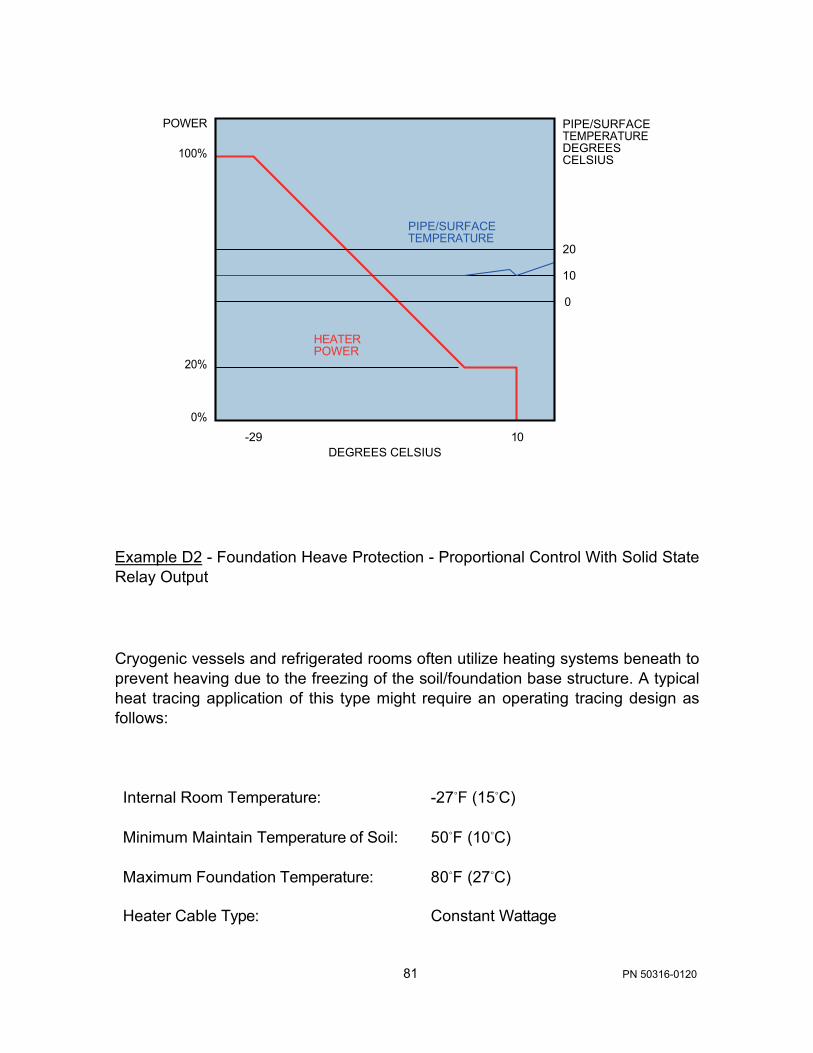
81 PN 50316-0120
POWER
100%
20%
0%
-29 10 DEGREES CELSIUS
PIPE/SURFACE TEMPERATURE DEGREES CELSIUS
20
10
0
Example D2 - Foundation Heave Protection - Proportional Control With Solid State Relay Output
Cryogenic vessels and refrigerated rooms often utilize heating systems beneath to prevent heaving due to the freezing of the soil/foundation base structure. A typical heat tracing application of this type might require an operating tracing design as follows:
Internal Room Temperature: -27◦F (15◦C)
Minimum Maintain Temperature of Soil: 50◦F (10◦C)
Maximum Foundation Temperature: 80◦F (27◦C)
Heater Cable Type: Constant Wattage
HEATER POWER
PIPE/SURFACE TEMPERATURE

82 PN 50316-0120
The TCM18 control module using foundation temperature sensing RTD’s in each heating zone can be typically set at the control settings given below:
Control Parameter Setting
Controller Configuration Single RTD Input
Control Method Proportional
100% Power On Temperature 50◦F (10◦C)
Control Band 30◦F (17◦C)
High Alarm Temperature 90◦F (32◦C)
High Temp Trip On
Low Alarm Temperature 38◦F (3◦C)
In a proportional control mode, the heater should be continually operating using cycle omission techniques in a warming mode (and will thus minimize condensation within the heating system conduits). After attaining 50◦F (10◦C), the TCM18 will linearly reduce power until an equilibrium value between 50◦F(10◦C), and 80◦F(27◦C), is obtained. In the unlikely event that the 80◦F (27◦C), setting is exceeded, the control will de-energize the heater circuit. A high temperature alarm will activate should the RTD sensor detect a temperature above the 90◦F (32◦C) value and the circuit will trip.
Having set in these values as well as the appropriate other limit/control values, the following typical control can be achieved.

83 PN 50316-0120
POWER
100%
20%
0% 10 27
DEGREES CELSIUS
Example D3 - Process Temperature Maintenance - Proportional Control With Solid State Relay Output
The TCM18 features the option of proportional control for those applications where close temperature control is required on process piping which may have varying process temperature conditions. A typical heat traced piping application might be a corn syrup viscosity control application. Due to the sensitivity of the syrup to color degradation the syrup must be maintained below 90◦F (32◦C). Typical heat tracing design requirements are listed as follows:
Syrup Maintain Temperature: 80◦F (27◦C)
Heater Cable Type: Constant Wattage
Maximum Syrup Temperature: 90◦F (32◦C)
TYPICAL SOIL CONTROLLED TEMPERATURE

84 PN 50316-0120
The TCM18 control module utilizing pipe sensing RTD’s could be typically set as shown below:
Controller Configuration Single RTD Input
Control Method Proportional
Maintain Temperature 80◦F (27◦C)
Control Band 9◦F (5◦C)
High Alarm Temperature 90◦F (32◦C)
High Temp Trip On
Low Alarm Temperature 75◦F (24◦C)
Power at Maintain Temp 100%
Having set in these values as well as the appropriate other limit/control values, the following typical control can be achieved.
POWER
100%
20%
0% 27 32
DEGREES CELSIUS
PIPE CONTROL TEMPERATURE
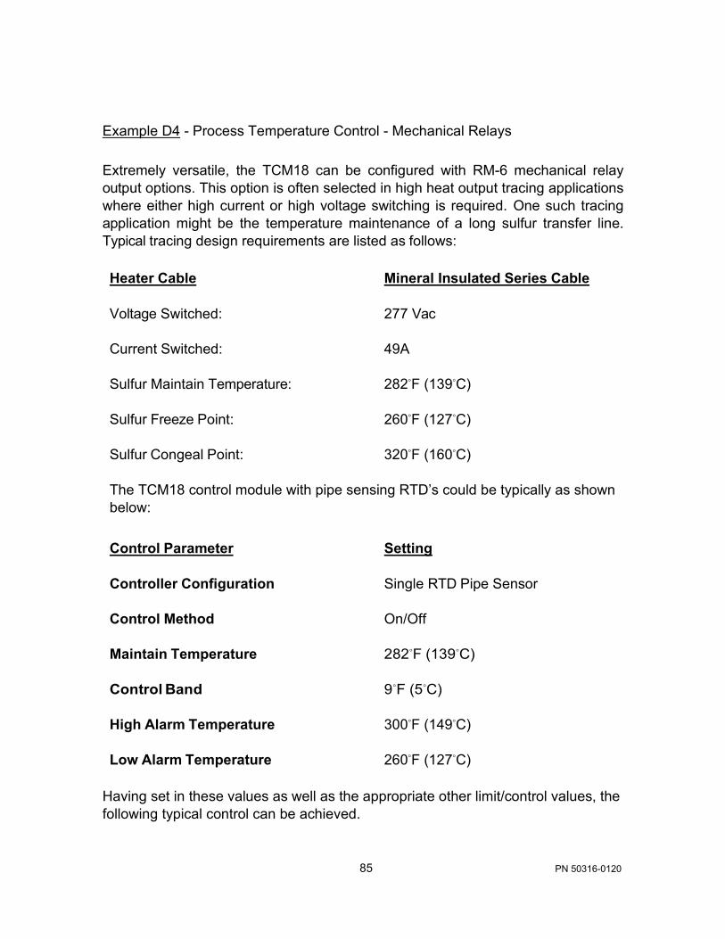
85 PN 50316-0120
Example D4 - Process Temperature Control - Mechanical Relays Extremely versatile, the TCM18 can be configured with RM-6 mechanical relay output options. This option is often selected in high heat output tracing applications where either high current or high voltage switching is required. One such tracing application might be the temperature maintenance of a long sulfur transfer line. Typical tracing design requirements are listed as follows:
Heater Cable Mineral Insulated Series Cable
Voltage Switched: 277 Vac
Current Switched: 49A
Sulfur Maintain Temperature: 282◦F (139◦C)
Sulfur Freeze Point: 260◦F (127◦C)
Sulfur Congeal Point: 320◦F (160◦C)
The TCM18 control module with pipe sensing RTD’s could be typically as shown below:
Control Parameter Setting
Controller Configuration Single RTD Pipe Sensor
Control Method On/Off
Maintain Temperature 282◦F (139◦C)
Control Band 9◦F (5◦C)
High Alarm Temperature 300◦F (149◦C)
Low Alarm Temperature 260◦F (127◦C)
Having set in these values as well as the appropriate other limit/control values, the following typical control can be achieved.

86 PN 50316-0120
PIPE TEMPERATURE DEGREES CELSIUS
144
139
TIME -+ Example D5 - Process Temperature Control - Dual RTD Sensing
It is sometimes considered advantageous to use dual RTD sensors on a critical heat tracing application such as a 50% caustic line. In this way, the power to the heater can be based on the input of two discrete temperature inputs rather than one. In addition, in the event of an RTD fault, the operator can be alarmed, the circuit can be acknowledged, and the RTD can be repaired without turning the heat tracing circuit OFF. For this application, the typical design requirements are as listed below:
Product Maintenance Temperature 80◦F (27◦C)
Product Freeze Point 54◦F (12◦C)
Heater Cable Type Self Regulating Parallel Cable
Maximum Caustic Temperature 100◦F (38◦C)

87 PN 50316-0120
The TCM18 control module utilizing pipe sensing RTD’s could be typically set as indicated below:
Control Parameter Setting
Controller Configuration Dual RTD Inputs
Control Method Proportional
Maintain Temperature 80◦F (27◦C)
Control Band 5◦F (3◦C)
High Alarm Temperature 90◦F (32◦C)
High Temperature Trip On
Low Alarm Temperature 60◦F (15◦C)
Power at Maintain Temp 100%
Considering that we have fifteen heat tracing circuits, the TCM18 would be set up with 30 RTD sensors.
The heat tracing circuit control assignments would be as follows:
Circuit No. Setting
1 thru 15 Enabled (2 Pipe) 16 thru 18 Spare
In this case power relays on circuits 16, 17, and 18 will not be connected to the heat tracing and because the circuits are listed as “Spare” they will not appear during the Scan Mode process.
Example D6 - Process Temperature and Ambient Sensing Control - Single and Dual RTD Sensing
In many applications there are a variety of control applications. Some may be the critical applications such as the 50% caustic in Example 5 and some may be simple water freeze protection. For this combination application, the typical design requirements are as listed below:

88 PN 50316-0120
Water Product Maintenance Temperature: 50◦F (10◦C) Product Freeze Point: 32◦F (0◦C) Heater Cable Type: Self Regulating Parallel Cable Number of Circuits: Ten Ambient Sensing
50% Caustic
Product Maintenance Temperature: 80◦F (27◦C) Product Freeze Point: 54◦F (12◦C) Heater Cable Type: Self Regulating Parallel Cable Maximum Caustic Temperature: 100◦F (38◦C) Number of Circuits: Eight Process Sensing
The TCM18 control module could be typically set as indicated below:
Control Parameter Setting
Controller Configuration 1 AMB/ 1 or 2 RTD Inputs
Control Method On-Off
Water Circuits Maintain Temperature 50◦F (10◦C) Control Band 5◦F (3◦C) High Alarm Temperature 120◦F (49◦C) High Temperature Trip Off Low Alarm Temperature 40◦F (5◦C)
Caustic Circuits Maintain Temperature 80◦F (27◦C) Control Band 5◦F (3◦C) High Alarm Temperature 90◦F (3◦C) High Temperature Trip On Low Alarm Temperature 60◦F (15◦C)

89 PN 50316-0120
The heat tracing circuit control assignments would be as follows:
Circuit No. Setting
1 thru 10 Enabled (Ambient Sensed Dual RTD’s) 11 thru 18 Enabled (Pipe Sensed Dual RTD’s)
In this case, power relays on circuits 1 thru 10 will be controlling ambient sensed circuits based on the RTD input on Circuit 1 and specifically RTD#1 and RTD#2. The remainder of Circuits (2-10) and associated power relays will be controlling based on the RTD inputs from Circuit 1 and will not have RTD’s populated on these circuits. Circuit 11 thru 18 and their associated power relays will be controlling based on the dual RTD inputs fed to each of their respective circuits.
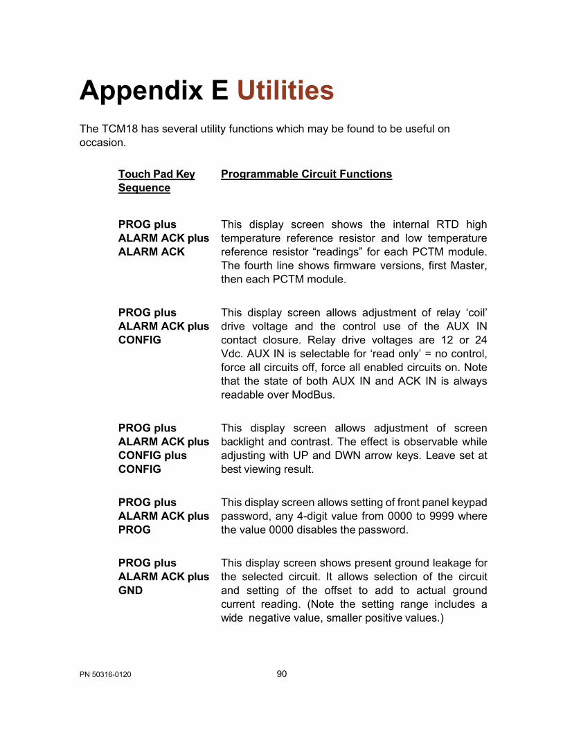
90 PN 50316-0120
Appendix E Utilities The TCM18 has several utility functions which may be found to be useful on occasion.
Touch Pad Key Sequence
Programmable Circuit Functions
PROG plus ALARM ACK plus ALARM ACK
This display screen shows the internal RTD high temperature reference resistor and low temperature reference resistor “readings” for each PCTM module. The fourth line shows firmware versions, first Master, then each PCTM module.
PROG plus ALARM ACK plus CONFIG
This display screen allows adjustment of relay ‘coil’ drive voltage and the control use of the AUX IN contact closure. Relay drive voltages are 12 or 24 Vdc. AUX IN is selectable for ‘read only’ = no control, force all circuits off, force all enabled circuits on. Note that the state of both AUX IN and ACK IN is always readable over ModBus.
PROG plus ALARM ACK plus CONFIG plus CONFIG
This display screen allows adjustment of screen backlight and contrast. The effect is observable while adjusting with UP and DWN arrow keys. Leave set at best viewing result.
PROG plus ALARM ACK plus PROG
This display screen allows setting of front panel keypad password, any 4-digit value from 0000 to 9999 where the value 0000 disables the password.
PROG plus ALARM ACK plus GND
This display screen shows present ground leakage for the selected circuit. It allows selection of the circuit and setting of the offset to add to actual ground current reading. (Note the setting range includes a wide negative value, smaller positive values.)

91 PN 50316-0120
Appendix F Markings for Hazardous Locations (Potentially Explosive Atmospheres) This Appendix applies to TraceNet TC Series panels without purge equipment. The TC Series panels have been certified to be in compliance with IEC 60079-0: 2011, IEC 60079-15: 2010, EN 60079-0: 2012, and EN 60079-15: 2010.
MARKINGS FOR TC SERIES PANELS
The panels may be marked 14.2710470X Ex nA IIC T4 Ge; AEx nA IIC T4 Ge, and/or II 3 G Ex nA IIC T4 Ge, along with Ta= -40°C to +55°C and IP54.

Thermon, Inc. 100 Thermon Drive San Marcos Texas www.thermon.com
Thermon PN 50316-0120