Embed Size (px)
Citation preview
Page 1
TR21202
Model Linear Structures: Aligning AutoCAD Civil 3D and Revit with Dynamo for Viaducts and Tunnels Ghassan Zein Dar Al-Handasah, Design Application Manager
Ian McGregor Autodesk, Snr Implementation Consultant - BIM - Co-Speaker
Description It is complex to model structures such as viaducts and tunnels that are controlled by an alignment and profile. Put that in an environment where the alignment changes often, and the structural engineer, using a tool like Revit software, finds it hard to accommodate that change. AutoCAD Civil 3D software is great for designing the alignment and profile—with complex curve elements and subassemblies for the mass modeling of complex structures—but we need Revit software for the detailed concrete modeling. Solutions to the challenge involving export/import of data between software have helped, but they present their own new challenges. This is where writing Dynamo scripts comes into play, providing integration and coordination between AutoCAD Civil 3D software and Revit software to give an interactive and dynamic modeling environment that can integrate structures like stairs and the MEP (mechanical, electrical, and plumbing)-required equipment. This class uses custom AutoCAD Civil 3D software subassemblies, Dynamo scripts, and Revit families. This session features AutoCAD Civil 3D, Dynamo, and Revit.
Your AU Experts
Ghassan Zein is the Design Application Manager / BIM Manager for Dar Al-Handasah. An
Architect by education, with over 25 years of experience in Architectural Design, Urban Planning, Project Management, Building Information Modeling and Geographic Information Systems, Ghassan has put his multi-faceted experience to the service of developing, adapting and optimizing BIM collaborative processes for Dar Al-Handasah, along with a team of BIM Specialists in all Dar Design Offices, with the aim of achieving better design quality and productivity through improved collaboration.
Ian McGregor is senior implementation consultant within the Building Information Modeling (BIM) service line at Autodesk, Inc. He is focused on assisting customers deliver BIM transformation within the infrastructure industry. He has extensive experience managing requirements for large and complex projects, and delivering across multiple engineering standards and languages. He also provides consultancy on BIM process definition and standardization for transportation, airports, and water industries.
Learning Objectives
Learn how to use AutoCAD Civil 3D to create the preliminary structure
Learn how to use Revit to add the detailed concrete elements
Learn how to use Dynamo scripting to manage and coordinate the model elements
Understand the impact of design change and iterate the design

Page 2
Outline of Handout Contents
Understanding the Linear Structures Modelling Challenge
Background Requirements gathering and prioritization Key technical challenges Key workflow challenges Adopted Approach
Tunnel Process
Workflow Overview
MODEL AUTHORING
Transportation team create road alignment/corridor Structure team create concrete tunnel Architecture team place rooms relative to corridor Structure team cut openings in tunnel MEP teams place MEP equipment and conduits in tunnel COORDINATION
Work in Progress Model Review DOCUMENTATION
Revit C3D for Structure Plan annotation All trade sections in Revit MODEL UPDATE / ITERATIONS Transportation team update road alignment/corridor Structure team update concrete tunnel Architecture team update rooms relative to corridor Structure team update openings in tunnel MEP team update MEP equipment and conduits
Bridge and Retaining Wall
Viaduct / Bridge Retaining Wall Counterfort Concrete artwork
Key Ingredients for Successful Adoption
Linear Reference system for AR/ST/MEP C3D for Structures Dynamo
Appendices
Software used Library of Dynamo utility nodes built for linear structures Glossary
Page 3
Understanding the Linear Structures Modelling Challenge
Background Dar have a long history in BIM for buildings and have executed many projects for hospitals, commercial premises, hotels and sports facilities: architectural, structural and MEP disciplines author their project BIM models and use them models for downstream processes such as Design Review and Coordination, Drawing Production, Visualisation and Cost Estimation.
However, BIM in the infrastructure environment has proven to be more of a challenge, with BIM standards less well defined than for buildings, while Clients are increasingly demanding BIM deliverables, e.g. coordinated models, in addition to drawings. Linear structures are a particular case in point: known workflows were a hybrid of 2D CAD and 3D BIM, which would no longer be acceptable, and the discipline design teams were at breaking point to manage modelling tasks that supported the mandated BIM workflows.
Dar decided to initiate a project with Autodesk to develop processes for the coordinated design of tunnels, viaducts and retaining walls across the design disciplines of Transportation, Structures, Architecture and MEP. This class is showing you some of the results of that project.
Requirements gathering and prioritization The project that was selected for this linear structure proof of concept is a large new airport in the Middle East, in concept design stage and moving into detailed design. Hundreds of kilometers of tunnels are planned in this airport to enable passenger, baggage and service vehicle movement. The adopted platforms are Civil 3D for transportation modelling (runways and taxiways, roads, surface modelling) and Revit for the other disciplines related to linear structures.
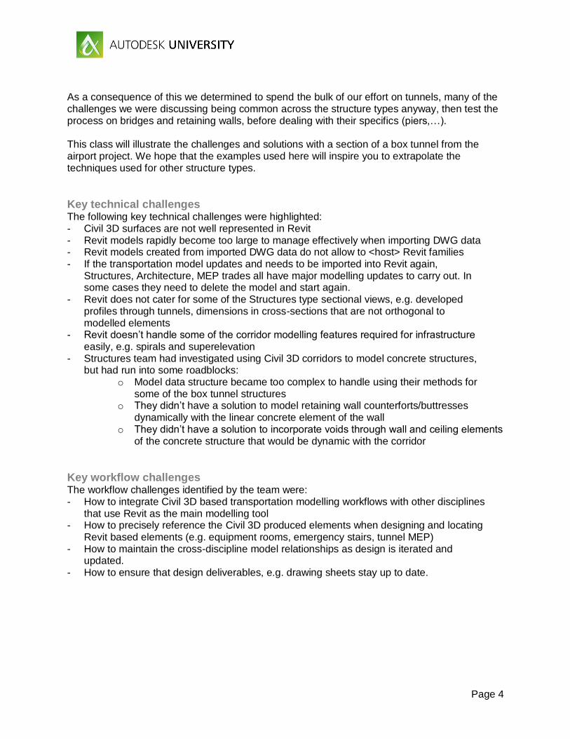
A two day workshop was held between Autodesk experts and Dar BIM team members to gather and prioritize the detailed requirements for our project. Dar’s BIM team consists of experts from all design trades who act as a development, training and support group for project teams in all design offices and are thus familiar with the challenges of current methods. Requirements, challenges and priorities were scrutinized and grouped to give a clearer picture of where focus during the project needed to be.
FIGURE 1 LINEAR STRUCTURES PROJECT REQUIREMENTS
Page 4
As a consequence of this we determined to spend the bulk of our effort on tunnels, many of the challenges we were discussing being common across the structure types anyway, then test the process on bridges and retaining walls, before dealing with their specifics (piers,…). This class will illustrate the challenges and solutions with a section of a box tunnel from the airport project. We hope that the examples used here will inspire you to extrapolate the techniques used for other structure types.
Key technical challenges The following key technical challenges were highlighted: - Civil 3D surfaces are not well represented in Revit - Revit models rapidly become too large to manage effectively when importing DWG data - Revit models created from imported DWG data do not allow to <host> Revit families - If the transportation model updates and needs to be imported into Revit again,
Structures, Architecture, MEP trades all have major modelling updates to carry out. In some cases they need to delete the model and start again.
- Revit does not cater for some of the Structures type sectional views, e.g. developed profiles through tunnels, dimensions in cross-sections that are not orthogonal to modelled elements
- Revit doesn’t handle some of the corridor modelling features required for infrastructure easily, e.g. spirals and superelevation
- Structures team had investigated using Civil 3D corridors to model concrete structures, but had run into some roadblocks:
o Model data structure became too complex to handle using their methods for some of the box tunnel structures
o They didn’t have a solution to model retaining wall counterforts/buttresses dynamically with the linear concrete element of the wall
o They didn’t have a solution to incorporate voids through wall and ceiling elements of the concrete structure that would be dynamic with the corridor
Key workflow challenges The workflow challenges identified by the team were: - How to integrate Civil 3D based transportation modelling workflows with other disciplines
that use Revit as the main modelling tool - How to precisely reference the Civil 3D produced elements when designing and locating
Revit based elements (e.g. equipment rooms, emergency stairs, tunnel MEP) - How to maintain the cross-discipline model relationships as design is iterated and
updated. - How to ensure that design deliverables, e.g. drawing sheets stay up to date.
Page 5
Adopted Approach It became clear that the Structures team were pivotal to creating a solution, as they provide the physical model that will be used as a basis and reference for the MEP trades and for non-linear elements such as rooms: if we found a modelling solution for Structures then that could enable all the other teams. The proposed approach consisted of the following:
- Structures teams should model linear elements in Civil 3D since that is the tool that understands a linear reference system of baseline and chainage.
- Structures should begin to reference Transportation corridor model elements not just the surface
- Structures team should coordinate a corridor code naming standard - Early investigations showed that linking an IFC file to Revit provided a number of
benefits to importing DWG files directly: o IFC retains properties set data exported from Civil 3D, [note: this can be useful
for other downstream BIM uses such as quantification, material schedules and adding phase data]
o IFC gives ability to select, hide and isolate sub-elements (solids regions) from the link, essentially behaving as a native Revit element. Using DWG you can only use the link visibility to switch off and on layers not elements.
o Elements created from IFC can be graphically overridden. o IFC imported geometry allows Revit to create section views on the model. DWG
import does not. o Autodesk tests show Revit file size reduction of up to 50% using IFC over DWG
import
- Structures should provide IFC file of corridor model elements to Revit to continue the modelling process
- Create a custom Dynamo package to introduce a linear reference system of baseline, chainage, offset and elevation (COE) to linear structures projects
- Produce a library of standard Dynamo graphs to allow trades to model: o Place linked Revit files at specific COE along the structure o Place equipment Revit families at specific COE along the structure o Place equipment Revit families at specific COE and at then at chainage intervals
along the structure o Use Dynamo to take Revit geometry to punch holes in Civil 3D corridor solids
The below sections walk through the key steps to engage the cross-discipline team in the modelling workflow.
Page 6
Tunnel Process
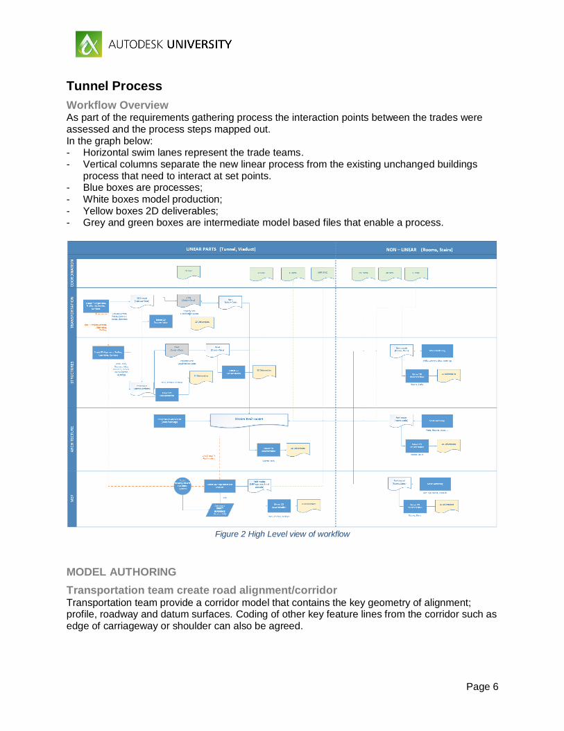
Workflow Overview As part of the requirements gathering process the interaction points between the trades were assessed and the process steps mapped out. In the graph below: - Horizontal swim lanes represent the trade teams. - Vertical columns separate the new linear process from the existing unchanged buildings
process that need to interact at set points. - Blue boxes are processes; - White boxes model production; - Yellow boxes 2D deliverables; - Grey and green boxes are intermediate model based files that enable a process.
Figure 2 High Level view of workflow
MODEL AUTHORING
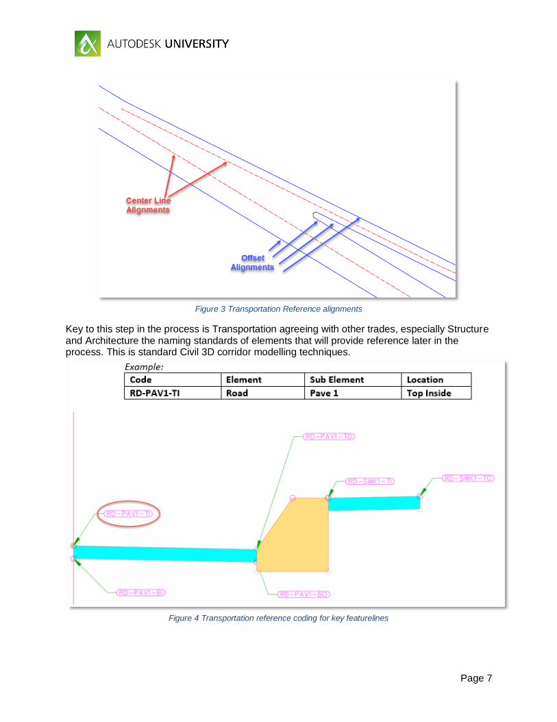
Transportation team create road alignment/corridor Transportation team provide a corridor model that contains the key geometry of alignment; profile, roadway and datum surfaces. Coding of other key feature lines from the corridor such as edge of carriageway or shoulder can also be agreed.
Page 7
Figure 3 Transportation Reference alignments
Key to this step in the process is Transportation agreeing with other trades, especially Structure and Architecture the naming standards of elements that will provide reference later in the process. This is standard Civil 3D corridor modelling techniques.
Figure 4 Transportation reference coding for key featurelines
Page 8
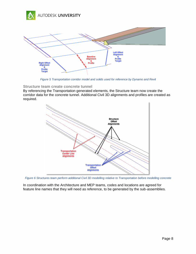
Figure 5 Transportation corridor model and solids used for reference by Dynamo and Revit
Structure team create concrete tunnel By referencing the Transportation generated elements, the Structure team now create the corridor data for the concrete tunnel. Additional Civil 3D alignments and profiles are created as required.
Figure 6 Structures team perform additional Civil 3D modelling relative to Transportation before modelling concrete
In coordination with the Architecture and MEP teams, codes and locations are agreed for feature line names that they will need as reference, to be generated by the sub-assemblies.
Page 9
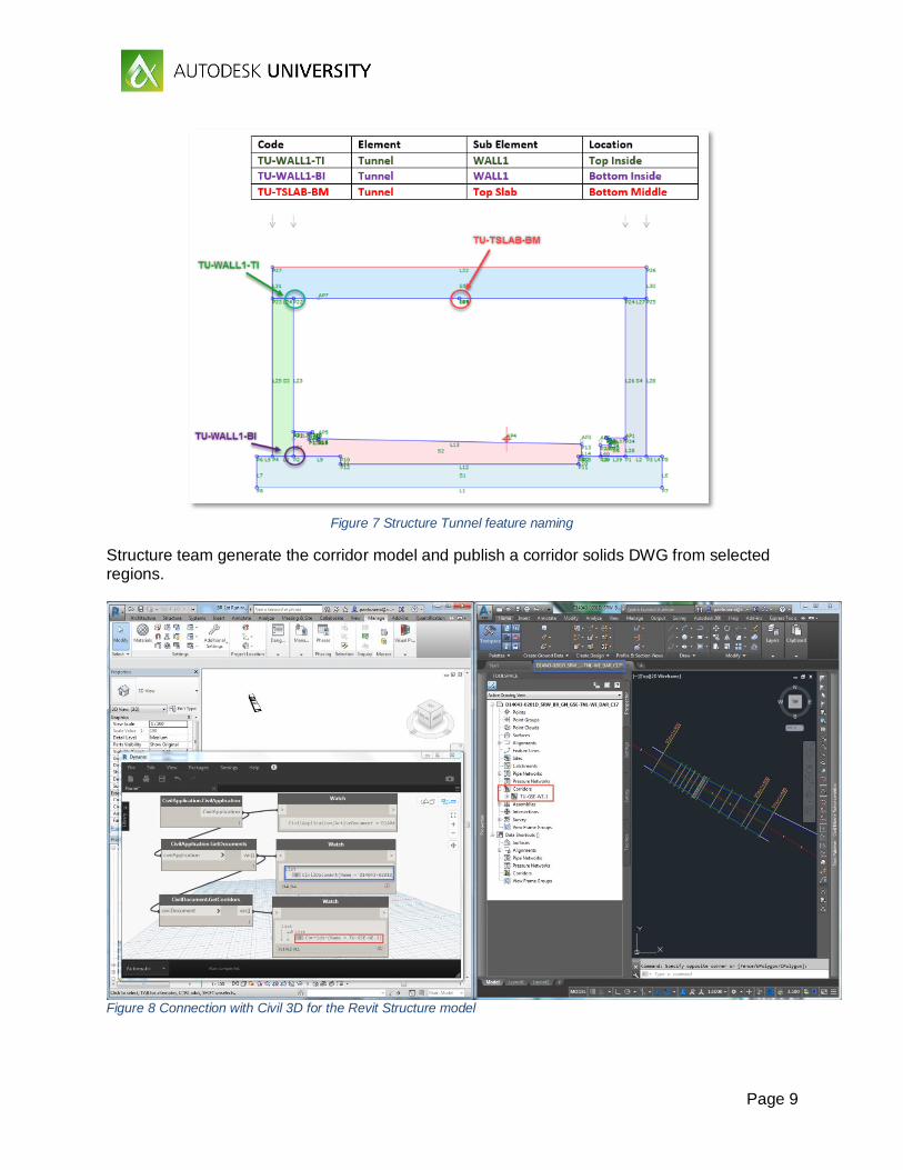
Figure 7 Structure Tunnel feature naming
Structure team generate the corridor model and publish a corridor solids DWG from selected regions.
Figure 8 Connection with Civil 3D for the Revit Structure model
Page 10
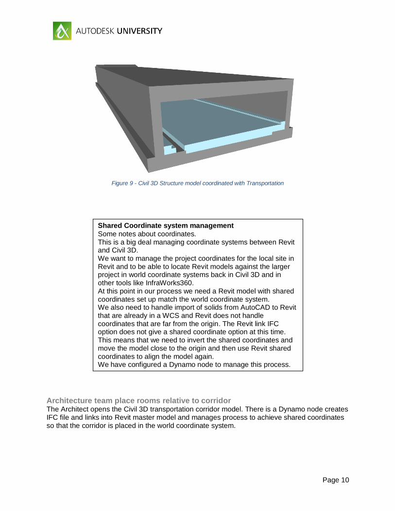
Figure 9 - Civil 3D Structure model coordinated with Transportation
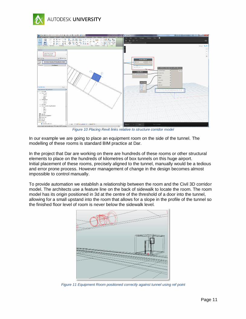
Architecture team place rooms relative to corridor The Architect opens the Civil 3D transportation corridor model. There is a Dynamo node creates IFC file and links into Revit master model and manages process to achieve shared coordinates so that the corridor is placed in the world coordinate system.
Shared Coordinate system management
Some notes about coordinates. This is a big deal managing coordinate systems between Revit and Civil 3D. We want to manage the project coordinates for the local site in Revit and to be able to locate Revit models against the larger project in world coordinate systems back in Civil 3D and in other tools like InfraWorks360. At this point in our process we need a Revit model with shared coordinates set up match the world coordinate system. We also need to handle import of solids from AutoCAD to Revit that are already in a WCS and Revit does not handle coordinates that are far from the origin. The Revit link IFC option does not give a shared coordinate option at this time. This means that we need to invert the shared coordinates and move the model close to the origin and then use Revit shared coordinates to align the model again. We have configured a Dynamo node to manage this process.
Page 11
Figure 10 Placing Revit links relative to structure corridor model
In our example we are going to place an equipment room on the side of the tunnel. The modelling of these rooms is standard BIM practice at Dar. In the project that Dar are working on there are hundreds of these rooms or other structural elements to place on the hundreds of kilometres of box tunnels on this huge airport. Initial placement of these rooms, precisely aligned to the tunnel, manually would be a tedious and error prone process. However management of change in the design becomes almost impossible to control manually. To provide automation we establish a relationship between the room and the Civil 3D corridor model. The architects use a feature line on the back of sidewalk to locate the room. The room model has its origin positioned in 3d at the centre of the threshold of a door into the tunnel, allowing for a small upstand into the room that allows for a slope in the profile of the tunnel so the finished floor level of room is never below the sidewalk level.
Figure 11 Equipment Room positioned correctly against tunnel using ref point
Page 12
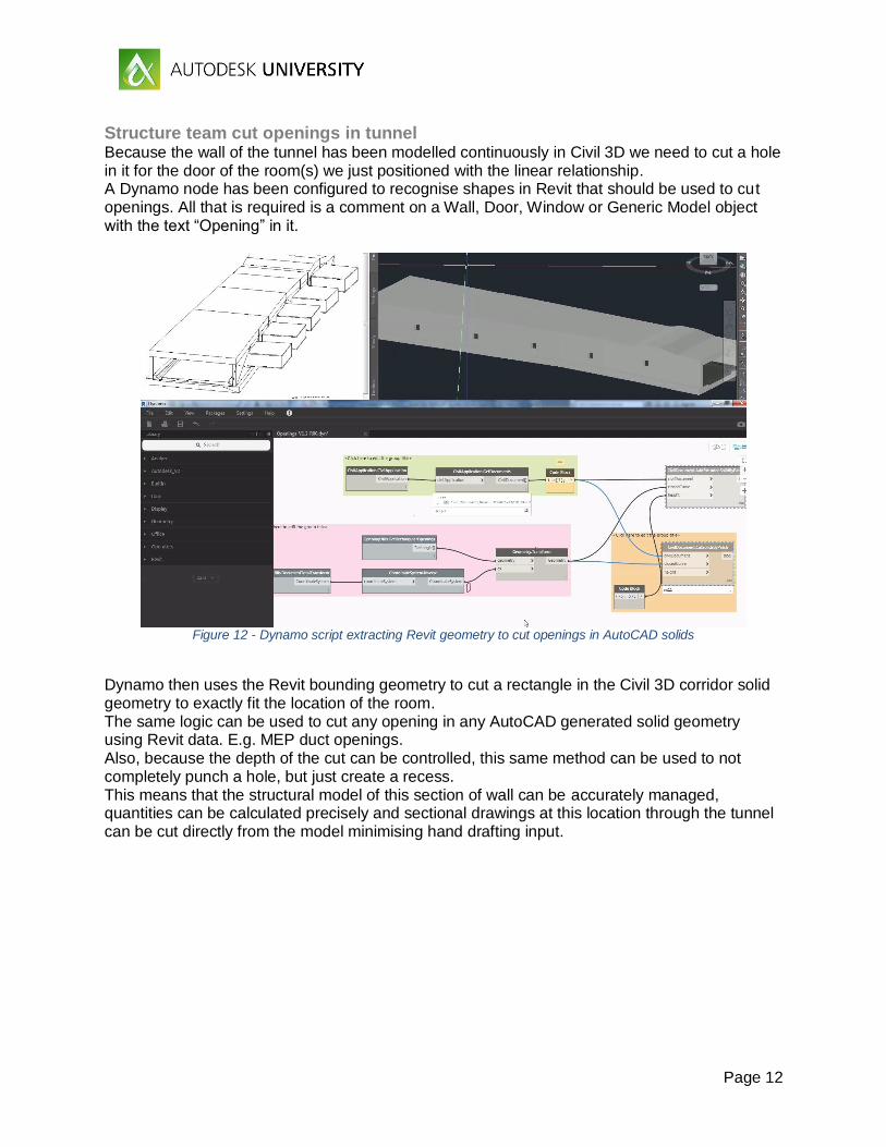
Structure team cut openings in tunnel Because the wall of the tunnel has been modelled continuously in Civil 3D we need to cut a hole in it for the door of the room(s) we just positioned with the linear relationship. A Dynamo node has been configured to recognise shapes in Revit that should be used to cut openings. All that is required is a comment on a Wall, Door, Window or Generic Model object with the text “Opening” in it.
Figure 12 - Dynamo script extracting Revit geometry to cut openings in AutoCAD solids
Dynamo then uses the Revit bounding geometry to cut a rectangle in the Civil 3D corridor solid geometry to exactly fit the location of the room. The same logic can be used to cut any opening in any AutoCAD generated solid geometry using Revit data. E.g. MEP duct openings. Also, because the depth of the cut can be controlled, this same method can be used to not completely punch a hole, but just create a recess. This means that the structural model of this section of wall can be accurately managed, quantities can be calculated precisely and sectional drawings at this location through the tunnel can be cut directly from the model minimising hand drafting input.
Page 13
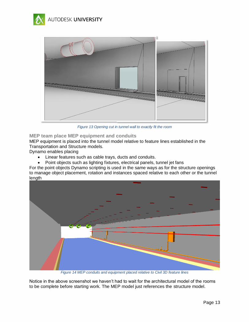
Figure 13 Opening cut in tunnel wall to exactly fit the room
MEP team place MEP equipment and conduits MEP equipment is placed into the tunnel model relative to feature lines established in the Transportation and Structure models. Dynamo enables placing
Linear features such as cable trays, ducts and conduits.
Point objects such as lighting fixtures, electrical panels, tunnel jet fans For the point objects Dynamo scripting is used in the same ways as for the structure openings to manage object placement, rotation and instances spaced relative to each other or the tunnel length
Figure 14 MEP conduits and equipment placed relative to Civil 3D feature lines
Notice in the above screenshot we haven’t had to wait for the architectural model of the rooms to be complete before starting work. The MEP model just references the structure model.
Page 14
COORDINATION Model based coordination is a well-established and familiar process at Dar on BIM projects, especially on the buildings teams. We wanted to establish linear structures projects as being able to participate in the same processes without having to change those.
Work in Progress Work in progress coordination means being able to consider the other disciplines at the time of carrying out your design work and receiving timely updates from those teams when they are aware they are making changes that may affect others. This can be termed clash avoidance rather than clash detection. This new linear structures process allows great visibility into other design teams’ activity because live data is being referenced without the need for a request to another party to publish information. This reduces the risk of using out of date information and increases collaboration.
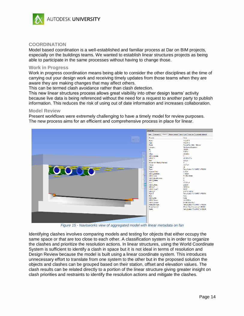
Model Review Present workflows were extremely challenging to have a timely model for review purposes. The new process aims for an efficient and comprehensive process in place for linear.
Figure 15 - Navisworks view of aggregated model with linear metadata on fan
Identifying clashes involves comparing models and testing for objects that either occupy the same space or that are too close to each other. A classification system is in order to organize the clashes and prioritize the resolution actions. In linear structures, using the World Coordinate System is sufficient to identify a clash in space but it is not ideal in terms of resolution and Design Review because the model is built using a linear coordinate system. This introduces unnecessary effort to translate from one system to the other but in the proposed solution the objects and clashes can be grouped based on their station, offset and elevation values. The clash results can be related directly to a portion of the linear structure giving greater insight on clash priorities and restraints to identify the resolution actions and mitigate the clashes.
Page 15
In Navisworks it is possible to create search sets using these values and the classification system to organize a linear structure model. The resolution actions can be reflected in the modifications of the station, offset and elevation parameters of the objects, Dynamo will update the location of the objects according to the new parameter values against the Civil 3D corridor input.
DOCUMENTATION
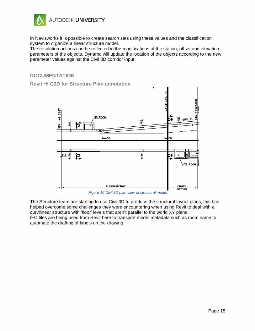
Revit C3D for Structure Plan annotation
Figure 16 Civil 3D plan view of structural model
The Structure team are starting to use Civil 3D to produce the structural layout plans, this has helped overcome some challenges they were encountering when using Revit to deal with a curvilinear structure with ‘floor’ levels that aren’t parallel to the world XY plane. IFC files are being used from Revit here to transport model metadata such as room name to automate the drafting of labels on the drawing.
Page 16
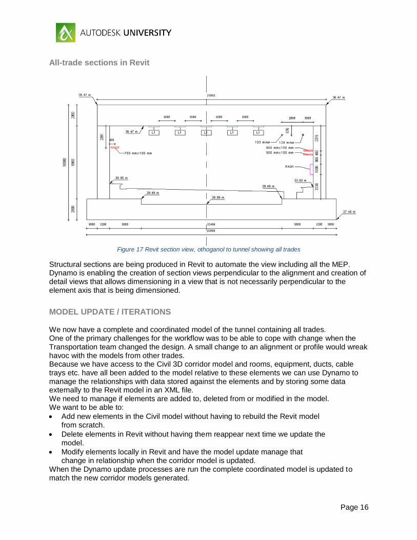
All-trade sections in Revit
Figure 17 Revit section view, othoganol to tunnel showing all trades
Structural sections are being produced in Revit to automate the view including all the MEP. Dynamo is enabling the creation of section views perpendicular to the alignment and creation of detail views that allows dimensioning in a view that is not necessarily perpendicular to the element axis that is being dimensioned.
MODEL UPDATE / ITERATIONS We now have a complete and coordinated model of the tunnel containing all trades. One of the primary challenges for the workflow was to be able to cope with change when the Transportation team changed the design. A small change to an alignment or profile would wreak havoc with the models from other trades. Because we have access to the Civil 3D corridor model and rooms, equipment, ducts, cable trays etc. have all been added to the model relative to these elements we can use Dynamo to manage the relationships with data stored against the elements and by storing some data externally to the Revit model in an XML file. We need to manage if elements are added to, deleted from or modified in the model. We want to be able to:
Add new elements in the Civil model without having to rebuild the Revit model from scratch.
Delete elements in Revit without having them reappear next time we update the model.
Modify elements locally in Revit and have the model update manage that change in relationship when the corridor model is updated.
When the Dynamo update processes are run the complete coordinated model is updated to match the new corridor models generated.
Page 17
Transportation Update road alignment/corridor In our sample project we had the transportation widen the road and modify the profile. All that was then required was to save the DWG and have the data shortcuts updated.
Structure team Update concrete tunnel The Structure team updated based on the new road design, and modified the tunnel roof to take account of the jet fan locations
Architecture Update rooms relative to corridor The architecture team then needed to update the room locations based on the new sidewalk definition from transportation. This is just a case of running two Dynamo scripts
Structure Update Openings in Tunnel The structure team now need to manage the new room locations and where the openings need to be in the tunnel wall. Run two Dynamo scripts.
MEP Update MEP Equipment and Conduits MEP team can now update their equipment, pipes, ducts and conduits. Run a Dynamo script for each.
Page 18
Bridge and Retaining Wall
We hope this class has given you some inspiration to investigate modelling linear structures more deeply. We are extremely enthusiastic about the new opportunities this methodology is opening up for us. Three further examples we tested to apply the same methods in other situations are shown for further inspiration below for you.
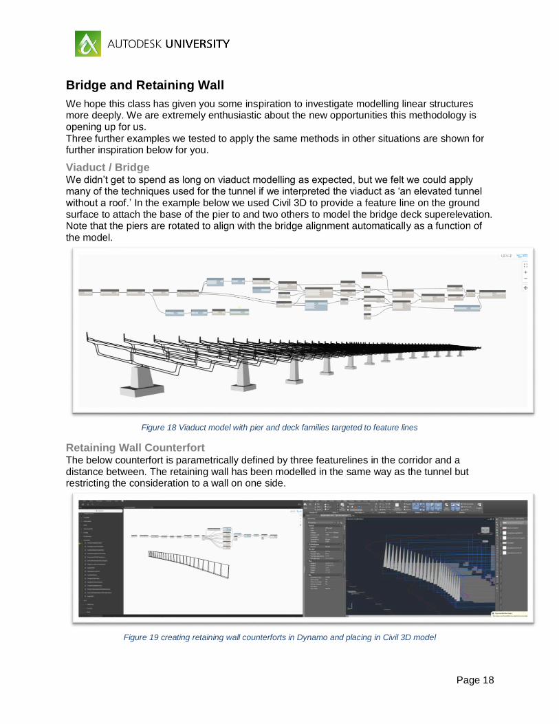
Viaduct / Bridge We didn’t get to spend as long on viaduct modelling as expected, but we felt we could apply many of the techniques used for the tunnel if we interpreted the viaduct as ‘an elevated tunnel without a roof.’ In the example below we used Civil 3D to provide a feature line on the ground surface to attach the base of the pier to and two others to model the bridge deck superelevation. Note that the piers are rotated to align with the bridge alignment automatically as a function of the model.
Figure 18 Viaduct model with pier and deck families targeted to feature lines
Retaining Wall Counterfort The below counterfort is parametrically defined by three featurelines in the corridor and a distance between. The retaining wall has been modelled in the same way as the tunnel but restricting the consideration to a wall on one side.
Figure 19 creating retaining wall counterforts in Dynamo and placing in Civil 3D model
Page 19
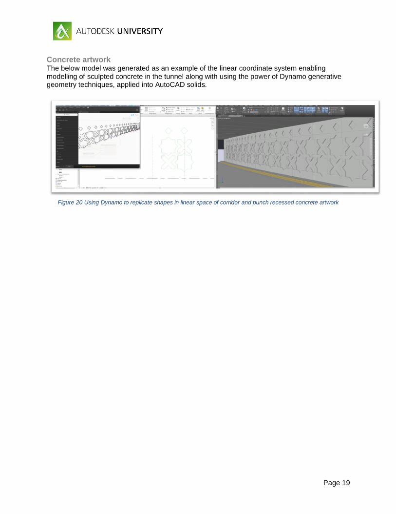
Concrete artwork The below model was generated as an example of the linear coordinate system enabling modelling of sculpted concrete in the tunnel along with using the power of Dynamo generative geometry techniques, applied into AutoCAD solids.
Figure 20 Using Dynamo to replicate shapes in linear space of corridor and punch recessed concrete artwork
Page 20
Key Ingredients for Successful Adoption
The adopted workflow promises substantial time saving, better modeling accuracy and even feasibility of tasks that were otherwise prohibitively complex or costly, through the maximized use of the right tools for the right tasks. The adoption of this approach however involves a learning curve for the various teams in the following key ingredients, which have been so far the realm of some trades but not others:
Linear Reference system for AR/ST/MEP One implication of establishing a linear reference in the structure, architecture and MEP models is that there is a location reference stored in the model that is extremely useful for downstream use. Contractors and owners will know where in the model they are located simply by looking at metadata attached to objects.
C3D for Structures The change in workflow for the Structures team is significant. They will be learning a new software having previously been trying to use Revit alone to develop their concrete structures. Now they will need to learn some Dynamo and Civil 3D as well. Custom training class development is underway to have structural engineers just learn the elements of Civil 3D they need to know.
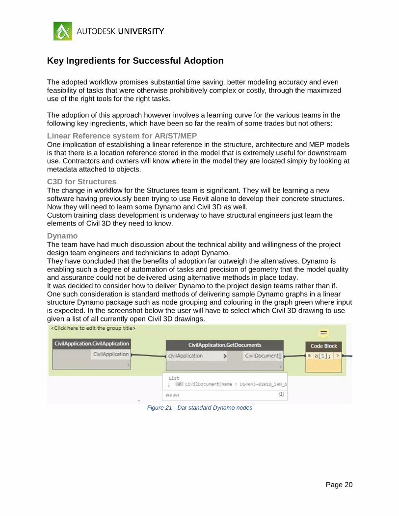
Dynamo The team have had much discussion about the technical ability and willingness of the project design team engineers and technicians to adopt Dynamo. They have concluded that the benefits of adoption far outweigh the alternatives. Dynamo is enabling such a degree of automation of tasks and precision of geometry that the model quality and assurance could not be delivered using alternative methods in place today. It was decided to consider how to deliver Dynamo to the project design teams rather than if. One such consideration is standard methods of delivering sample Dynamo graphs in a linear structure Dynamo package such as node grouping and colouring in the graph green where input is expected. In the screenshot below the user will have to select which Civil 3D drawing to use given a list of all currently open Civil 3D drawings.
Figure 21 - Dar standard Dynamo nodes
Page 21
Appendices
Software used AutoCAD Civil 3D 2017 (requires at least 2016 for IFC out from Civil 3D) Revit 2017.1 Dynamo 1.2 Navisworks 2017
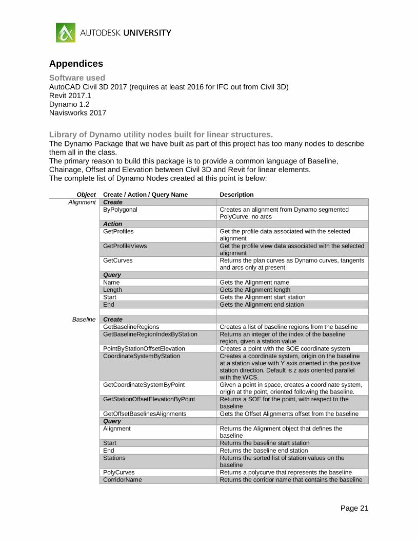
Library of Dynamo utility nodes built for linear structures. The Dynamo Package that we have built as part of this project has too many nodes to describe them all in the class. The primary reason to build this package is to provide a common language of Baseline, Chainage, Offset and Elevation between Civil 3D and Revit for linear elements. The complete list of Dynamo Nodes created at this point is below:
Object Create / Action / Query Name Description
Alignment Create
ByPolygonal Creates an alignment from Dynamo segmented PolyCurve, no arcs
Action
GetProfiles Get the profile data associated with the selected alignment
GetProfileViews Get the profile view data associated with the selected alignment
GetCurves Returns the plan curves as Dynamo curves, tangents and arcs only at present
Query
Name Gets the Alignment name
Length Gets the Alignment length
Start Gets the Alignment start station
End Gets the Alignment end station
Baseline Create
GetBaselineRegions Creates a list of baseline regions from the baseline
GetBaselineRegionIndexByStation Returns an integer of the index of the baseline region, given a station value
PointByStationOffsetElevation Creates a point with the SOE coordinate system
CoordinateSystemByStation Creates a coordinate system, origin on the baseline at a station value with Y axis oriented in the positive station direction. Default is z axis oriented parallel with the WCS.
GetCoordinateSystemByPoint Given a point in space, creates a coordinate system, origin at the point, oriented following the baseline.
GetStationOffsetElevationByPoint Returns a SOE for the point, with respect to the baseline
GetOffsetBaselinesAlignments Gets the Offset Alignments offset from the baseline
Query
Alignment Returns the Alignment object that defines the baseline
Start Returns the baseline start station
End Returns the baseline end station
Stations Returns the sorted list of station values on the baseline
PolyCurves Returns a polycurve that represents the baseline
CorridorName Returns the corridor name that contains the baseline
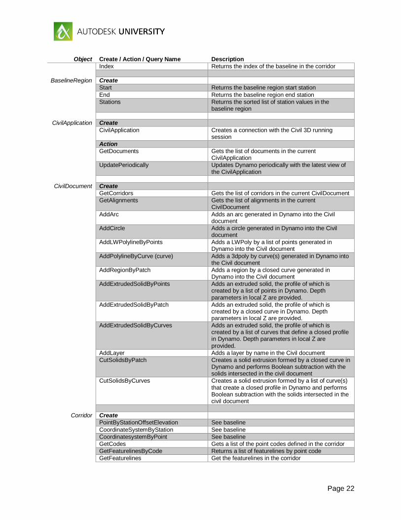
Page 22
Object Create / Action / Query Name Description
Index Returns the index of the baseline in the corridor
BaselineRegion Create
Start Returns the baseline region start station
End Returns the baseline region end station
Stations Returns the sorted list of station values in the baseline region
CivilApplication Create
CivilApplication Creates a connection with the Civil 3D running session
Action
GetDocuments Gets the list of documents in the current CivilApplication
UpdatePeriodically Updates Dynamo periodically with the latest view of the CivilApplication
CivilDocument Create
GetCorridors Gets the list of corridors in the current CivilDocument
GetAlignments Gets the list of alignments in the current CivilDocument
AddArc Adds an arc generated in Dynamo into the Civil document
AddCircle Adds a circle generated in Dynamo into the Civil document
AddLWPolylineByPoints Adds a LWPoly by a list of points generated in Dynamo into the Civil document
AddPolylineByCurve (curve) Adds a 3dpoly by curve(s) generated in Dynamo into the Civil document
AddRegionByPatch Adds a region by a closed curve generated in Dynamo into the Civil document
AddExtrudedSolidByPoints Adds an extruded solid, the profile of which is created by a list of points in Dynamo. Depth parameters in local Z are provided.
AddExtrudedSolidByPatch Adds an extruded solid, the profile of which is created by a closed curve in Dynamo. Depth parameters in local Z are provided.
AddExtrudedSolidByCurves Adds an extruded solid, the profile of which is created by a list of curves that define a closed profile in Dynamo. Depth parameters in local Z are provided.
AddLayer Adds a layer by name in the Civil document
CutSolidsByPatch Creates a solid extrusion formed by a closed curve in Dynamo and performs Boolean subtraction with the solids intersected in the civil document
CutSolidsByCurves Creates a solid extrusion formed by a list of curve(s) that create a closed profile in Dynamo and performs Boolean subtraction with the solids intersected in the civil document
Corridor Create
PointByStationOffsetElevation See baseline
CoordinateSystemByStation See baseline
CoordinatesystemByPoint See baseline
GetCodes Gets a list of the point codes defined in the corridor
GetFeaturelinesByCode Returns a list of featurelines by point code
GetFeaturelines Get the featurelines in the corridor
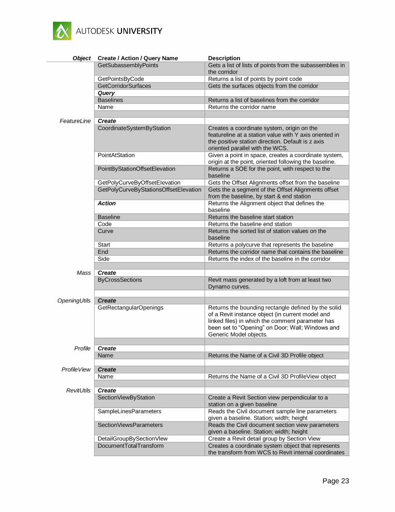
Page 23
Object Create / Action / Query Name Description
GetSubassemblyPoints Gets a list of lists of points from the subassemblies in the corridor
GetPointsByCode Returns a list of points by point code
GetCorridorSurfaces Gets the surfaces objects from the corridor
Query
Baselines Returns a list of baselines from the corridor
Name Returns the corridor name
FeatureLine Create
CoordinateSystemByStation Creates a coordinate system, origin on the featureline at a station value with Y axis oriented in the positive station direction. Default is z axis oriented parallel with the WCS.
PointAtStation Given a point in space, creates a coordinate system, origin at the point, oriented following the baseline.
PointByStationOffsetElevation Returns a SOE for the point, with respect to the baseline
GetPolyCurveByOffsetEIevation Gets the Offset Alignments offset from the baseline
GetPolyCurveByStationsOffsetElevation Gets the a segment of the Offset Alignments offset from the baseline, by start & end station
Action Returns the Alignment object that defines the baseline
Baseline Returns the baseline start station
Code Returns the baseline end station
Curve Returns the sorted list of station values on the baseline
Start Returns a polycurve that represents the baseline
End Returns the corridor name that contains the baseline
Side Returns the index of the baseline in the corridor
Mass Create
ByCrossSections Revit mass generated by a loft from at least two Dynamo curves.
OpeningUtils Create
GetRectangularOpenings Returns the bounding rectangle defined by the solid of a Revit instance object (in current model and linked files) in which the comment parameter has been set to “Opening” on Door; Wall; Windows and Generic Model objects.
Profile Create
Name Returns the Name of a Civil 3D Profile object
ProfileView Create
Name Returns the Name of a Civil 3D ProfileView object
RevitUtils Create
SectionViewByStation Create a Revit Section view perpendicular to a station on a given baseline
SampleLinesParameters Reads the Civil document sample line parameters given a baseline. Station; width; height
SectionViewsParameters Reads the Civil document section view parameters given a baseline. Station; width; height
DetailGroupBySectionVlew Create a Revit detail group by Section View
DocumentTotalTransform Creates a coordinate system object that represents the transform from WCS to Revit internal coordinates
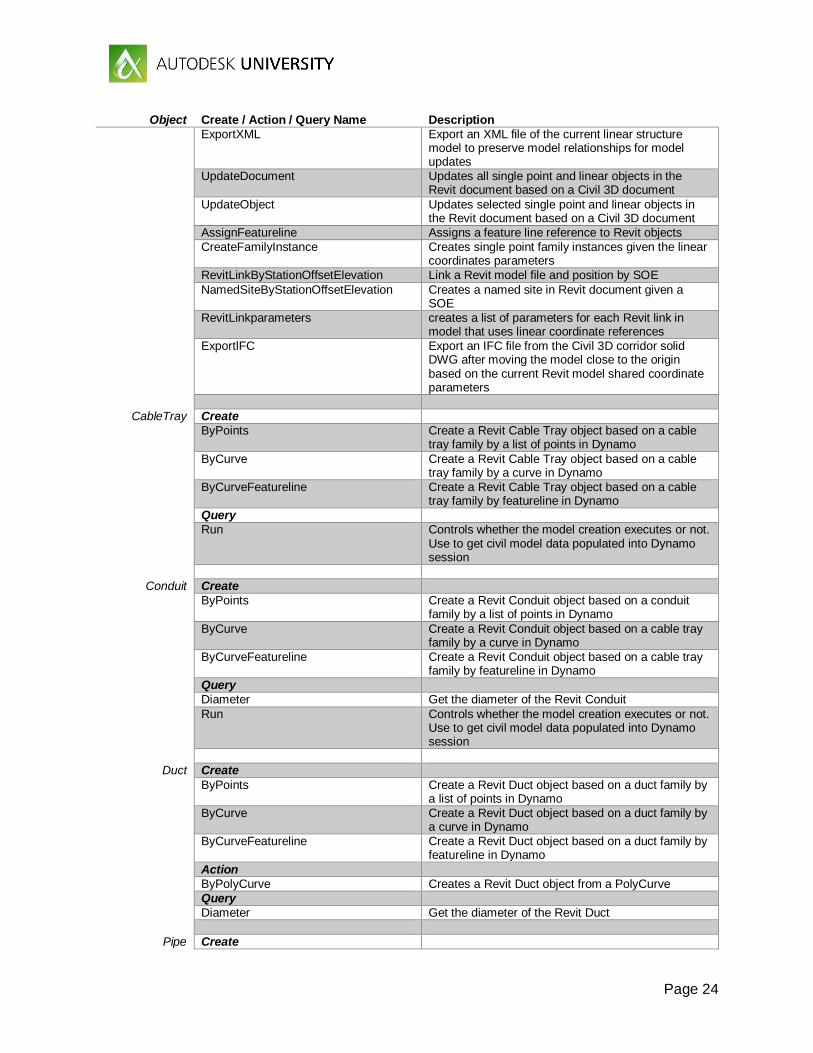
Page 24
Object Create / Action / Query Name Description
ExportXML Export an XML file of the current linear structure model to preserve model relationships for model updates
UpdateDocument Updates all single point and linear objects in the Revit document based on a Civil 3D document
UpdateObject Updates selected single point and linear objects in the Revit document based on a Civil 3D document
AssignFeatureline Assigns a feature line reference to Revit objects
CreateFamilyInstance Creates single point family instances given the linear coordinates parameters
RevitLinkByStationOffsetElevation Link a Revit model file and position by SOE
NamedSiteByStationOffsetElevation Creates a named site in Revit document given a SOE
RevitLinkparameters creates a list of parameters for each Revit link in model that uses linear coordinate references
ExportlFC Export an IFC file from the Civil 3D corridor solid DWG after moving the model close to the origin based on the current Revit model shared coordinate parameters
CableTray Create
ByPoints Create a Revit Cable Tray object based on a cable tray family by a list of points in Dynamo
ByCurve Create a Revit Cable Tray object based on a cable tray family by a curve in Dynamo
ByCurveFeatureline Create a Revit Cable Tray object based on a cable tray family by featureline in Dynamo
Query
Run Controls whether the model creation executes or not. Use to get civil model data populated into Dynamo session
Conduit Create
ByPoints Create a Revit Conduit object based on a conduit family by a list of points in Dynamo
ByCurve Create a Revit Conduit object based on a cable tray family by a curve in Dynamo
ByCurveFeatureline Create a Revit Conduit object based on a cable tray family by featureline in Dynamo
Query
Diameter Get the diameter of the Revit Conduit
Run Controls whether the model creation executes or not. Use to get civil model data populated into Dynamo session
Duct Create
ByPoints Create a Revit Duct object based on a duct family by a list of points in Dynamo
ByCurve Create a Revit Duct object based on a duct family by a curve in Dynamo
ByCurveFeatureline Create a Revit Duct object based on a duct family by featureline in Dynamo
Action
ByPolyCurve Creates a Revit Duct object from a PolyCurve
Query
Diameter Get the diameter of the Revit Duct
Pipe Create
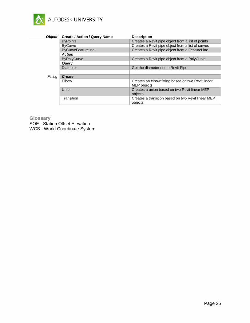
Page 25
Object Create / Action / Query Name Description
ByPoints Creates a Revit pipe object from a list of points
ByCurve Creates a Revit pipe object from a list of curves
ByCurveFeatureline Creates a Revit pipe object from a FeatureLine
Action
ByPolyCurve Creates a Revit pipe object from a PolyCurve
Query
Diameter Get the diameter of the Revit Pipe
Fitting Create
Elbow Creates an elbow fitting based on two Revit linear MEP objects
Union Creates a union based on two Revit linear MEP objects
Transition Creates a transition based on two Revit linear MEP objects
Glossary SOE - Station Offset Elevation WCS - World Coordinate System