Embed Size (px)
Citation preview
Gross Pollutant Traps
as a Stormwater
Management
Practice Literature Review
June 2011
Auckland Council
Technical Report No 2011/006
ISSN 2230-4525 (Print)
ISSN 2230-4533 (Online)
ISBN 978-1-927169-10-0 (Print)
ISBN 978-1-927169-11-7 (PDF)
Technical Report, first edition
Technical Reviewed by: Approved for AC Publication by:
Name: Grace Wong Name: Matthew D Davis
Stormwater Technical Specialist Manager Development and Technical
Services Stormwater
Organisation: Auckland Council Organisation: Auckland Council
Date: 30 June 2011 Date: 30 June 2011
Recommended Citation:
Fitzgerald, B. and Bird, W. (2010). Literature Review: Gross Pollutant Traps as a
Stormwater Management Practice. Auckland Council Technical Report 2011/006.
© 2011 Auckland Council
This publication is provided strictly subject to Auckland Council's copyright and other intellectual property
rights (if any) in the publication. Users of the publication may only access, reproduce and use the publication,
in a secure digital medium or hard copy, for responsible genuine non-commercial purposes relating to
personal, public service or educational purposes, provided that the publication is only ever accurately
reproduced and proper attribution of its source, publication date and authorship is attached to any use or
reproduction. This publication must not be used in any way for any commercial purpose without the prior
written consent of Auckland Council. Auckland Council does not give any warranty whatsoever, including
without limitation, as to the availability, accuracy, completeness, currency or reliability of the information or
data (including third party data) made available via the publication and expressly disclaim (to the maximum
extent permitted in law) all liability for any damage or loss resulting from your use of, or reliance on the
publication or the information and data provided via the publication. The publication and information and data
contained within it are provided on an "as is" basis.

Gross Pollutant Traps
as a Stormwater
Management Practice - Literature Review:
Bridget Fitzgerald
Warren S Bird
Prepared for
Auckland Council

Contents
Executive Summary 1
1 Introduction 3
1.1 Project Scope and Purpose 3
1.2 Acronym List 3
2 Purpose of a Gross Pollutant Trap 5
2.1 Definition of Gross Pollutants 6
3 Types of Gross Pollutant Traps 8
3.1 GPTs as Part of a Treatment Train 8
3.2 General Limitations of GPTs 10
3.3 Structural and Non-Structural Methods 11
3.4 GPT Treatment Mechanisms and Types 11
3.5 Catchpit Grates and Entrance Screens 13
3.6 Side Entry Pit Trap (SEPT) 16
3.7 Baffled Pits (Trapped Street Gullies) 19
3.8 Trash Racks 21
3.9 Litter Control Devices (LCD) 22
3.10 Fixed Trash Traps 24
3.11 Booms and Floating Traps 26
3.12 Circular Screen / Hydrodynamic Deflective Separation (HDS) Devices 28
4 Considerations when selecting a GPT 32
4.1 Pre-requirements 32
4.2 Treatment Performance Objectives 32
4.3 Design Flows 33
4.4 Flood Capacity 33
4.5 Trapped Pollutant Storage 34
4.6 Maintenance Requirements 34
4.7 Site Suitability Assessment 35
4.8 Cost Considerations when selecting a GPT 36
4.8.1 Installation Costs 36
4.8.2 Maintenance Costs 37
4.8.3 Disposal Costs 37
4.8.4 Wet versus Dry Loads 38
4.8.5 Whole-of-Life Costs 38
4.9 Device Selection Matrix 39
5 Operation and Maintenance 40
5.1 Why Regular Maintenance is Critical 40
5.2 Developing a Monitoring and Maintenance Plan 40
5.3 Maintenance Operations 42
5.4 Check Lists 43
6 Summary 45
7 References 47
8 Bibliography 48
9 APPENDIX 1: Device Selection Matrix 1
10 APPENDIX 2: Checklists 1
10.1 Selecting a GPT Checklist 1
10.2 Design Calculation Checklist 2
10.3 Maintenance Inspection Checklist 3
10.4 Life Cycle Costs Checklist 5

Gross Pollutant Traps as a Stormwater Management Practice: Literature Review 1
Executive Summary
Despite ongoing education, awareness and street cleaning programmes, large amounts of
gross pollutants (litter, debris and sediment greater than 5 mm in size) are reaching
stormwater systems and degrading receiving water environments. All forms of
development and land use generate gross pollutants which are a threat to wildlife and
aquatic habitats. These pollutants are also aesthetically unpleasant, may cause odour
problems and may attract vermin.
There are numerous techniques available for removing gross pollutants from the receiving
environment. The most effective strategies involve a combination of non-structural
measures (e.g. education and waste management programmes, and source controls) and
structural treatments (installation of Gross Pollutant Traps).
While not widely implemented in New Zealand to date, Gross Pollutant Traps (GPTs) have
been used internationally to improve water quality. They are generally used as primary
treatment to assist and improve the function of other treatment devices designed to
remove finer fraction contaminants. Sometimes, where gross pollutants themselves are
perceived as unacceptable, GPTs may be installed in isolation.
Provided appropriate GPT selection, design and maintenance regimes are implemented,
there are applications within the wider Auckland area where GPTs would be beneficial.
However, due to a lack of selection criteria, design guidance and practical local examples
there has been limited uptake by developers and local councils.
Currently the Proposed Auckland Regional Council: Air, Land and Water Plan (PARC-
ALW Plan) requires the removal of 75% of total suspended solids from new impervious
surfaces on a long term average basis. ARC’s TP10 best practice document, Stormwater
Management Devices: Design Guidelines Manual details a number of techniques for
achieving the ALW Plan objective. Both documents presume that the removal of sediment
will also inherently remove some of the other contaminants of concern, including
particulate trace metals, particulate nutrients, oil and grease on sediments and bacteria on
sediments.
Stand-alone GPTs are considered most appropriate for use in retro-fit situations as a
primary treatment device to target gross pollutants. GPTs must only be used in
conjunction with appropriate maintenance regimes to ensure that the treatment
performance of the GPT is maintained.
The whole of life cost for each GPT is critical, with maintenance costs often being
overlooked or dramatically underestimated, and the development of a catchment-specific
maintenance programme over time to optimise overall efficiency is highly recommended.

Gross Pollutant Traps as a Stormwater Management Practice: Literature Review 2
Disposal costs are also a key maintenance element that is often not given enough
consideration during the design phase.
This literature review of national and international resources indicates that the following
key aspects should be considered critical with regard to the use of GPTs in the Auckland
region:
Site specific characteristics
Treatment objectives
Device selection
Design features
Maintenance and operational requirements
GPTs available on the market vary greatly in their treatment mechanism, effectiveness,
efficiency, proven life performance, operational monitoring and maintenance requirements
and cost. No devices available on the market are identical; therefore careful consideration
is needed to ensure appropriate devices are considered for site-specific conditions.
Many GPT performance claims are made by manufacturers based on limited test data,
using test methods that may lack scientific rigour. Stormwater designers are
recommended to critically check the claimed performance efficiency results of specific
devices, examine the conditions the results were obtained under, and ensure testing is
independent.
Gross Pollutant Traps as a Stormwater Management Practice: Literature Review 3
1 Introduction 1.1 Project Scope and Purpose
The current design guidelines (TP10) provide limited information with regard to the
definition of gross pollutants and Gross Pollutant Traps (GPTs), therefore the scope of this
project has been to bridge these knowledge gaps and address the following:
Identify the various types of devices currently available, with performance
achievements, benefits and limitations outlined
Carry out a literature review of design factors, methodologies low flow and high
flow bypass systems for various devices
Confirm key device selection considerations and criteria
Outline specific maintenance requirements for the Auckland region
By examining local and international research and design guidelines to establish best
practice, this report aims to develop improved selection criteria for GPTs in the Auckland
region. This report presents aspects of GPT implementation including appropriate selection
and design considerations, construction, maintenance and operation.
This report does not attempt to set an Auckland region wide gross pollutant treatment
objective. Therefore the implementation of GPTs will continue to occur in selected
catchments on a site specific basis. Requirements need to be considered on a catchment
by catchment basis, and this report details key selection, design, construction and
operational monitoring and maintenance aspects to consider once the need for a GPT has
been established.
This report discusses the GPT types available on the market, along with their benefits and
limitations. Whilst this report may name companies and/or products, the Auckland Council
does not endorse any particular product or company. The naming of a product or company
is purely to discuss the current methods available in the market for GPTs. It is
acknowledged that other products may be available (or have become available since the
time of writing).
1.2 Acronym List
For the purposes of this report, the following acronyms apply:
ARC – Auckland Regional Council
CFS – Catchpit Filter System
FDT – Floating Debris Trap
Gross Pollutant Traps as a Stormwater Management Practice: Literature Review 4
GPT – Gross Pollutant Trap
HDS – Hydrodynamic Deflective Separation
LCD - Litter Control Device
PARC-ALWP – Proposed Auckland Regional Council Air, Land and Water Plan
SEPT – Side Entry Pit Trap
TP – Technical Publication
TSS – Total Suspended Solids
WQV – Water Quality Volume

Gross Pollutant Traps as a Stormwater Management Practice: Literature Review 5
2 Purpose of a Gross Pollutant Trap Gross Pollutant Traps (GPTs) are devices used for water quality control that remove solids
typically greater than five millimetres conveyed by stormwater runoff.
The term ‚gross pollutant‛ when used in connection with stormwater drainage systems
can include litter, debris and coarse sediments. Litter is defined as human-derived material
including paper, plastics, metals, glass and cloth. Debris is defined as any organic material
transported by stormwater (such as leaves, twigs and grass clippings). Sediments are
defined as inorganic particulates. While all gross pollutants are not 100% human derived,
human activities are likely responsible for an exponential increase in pollutants over
predevelopment conditions.
The primary purpose of GPTs is to remove gross pollutants (>5 mm) washed into the
stormwater system before the stormwater enters the receiving waters. They generally
collect larger items from the water, such as containers, leaves, bottles and plastic bags.
Smaller pollutants, such as dirt, chemicals, heavy metals and bacteria are not collected
directly by the GPTs; however, some small particles are caught up in the larger items
removed, and thus prevented from reaching the receiving water.
There are two primary characteristics that determine the long term effectiveness and
performance of a gross pollutant trapping system: the gross pollutant trapping efficiency
and the maintenance requirements.
The trapping efficiency of a device is defined as the proportion of the total mass of gross
pollutants transported by stormwater that is retained by the trap. A trap with a low
trapping efficiency means that a high proportion of the gross pollutants transported by the
stormwater are passing through the trap and reaching downstream waters (Allison, et al.,
1998).
The typical application for GPTs is within a residential suburb, commercial or industrial
area, highway or on a catchment-wide scale. A localised residential or commercial system
might involve smaller traps in side inlet catchpit systems that filter runoff from a smaller
sub-catchment area. A catchment-wide system may include racks and booms across
rivers, streams and major stormwater channels, or at the base of the catchment. Racks
typically catch debris far greater in size than 5 mm, while booms generally capture floating
pollutants (and contaminants attached to the floating pollutants).
GPTs can operate in isolation to reduce pollutant effects within immediate downstream
receiving waters, or as part of a more comprehensive treatment train system to prevent
overload of downstream infrastructure or treatment devices.

Gross Pollutant Traps as a Stormwater Management Practice: Literature Review 6
GPTs do not contribute to flood control. If not maintained GPTs can contribute to an
increase in flooding by generating additional backwater effects, therefore careful selection
and design is required.
2.1 Definition of Gross Pollutants
Based on international standards, gross pollutants are generally defined as material that
would be retained by a five millimetre mesh screen. Therefore it can be assumed that only
sediments that are attached to litter and debris would be captured as a gross pollutant.
Figures 1 and 2 below show the general makeup of gross pollutants and litter by mass
within an urban area based on field studies (Allison et al., 1997).
Figure 1: Composition of urban gross pollutants by mass (Allison et al., 1997)
Figure 2: Composition of urban litter by mass (Allison et al., 1997)
Personal Paper
Personal Plastic
Vegetation
Commercial PlasticMetals
Other
Other
Personal Plastic
Cigarette Butts
Commercial Plastic
Paper
Metals

Gross Pollutant Traps as a Stormwater Management Practice: Literature Review 7
Several studies have been completed internationally to assess the makeup of gross
pollutants in the field, including well known studies by Allison et al. (1997, 1998a, 1998b)
for the Coburg catchment. This catchment, 8 km north of central Melbourne, is considered
a typical inner city suburban catchment.
It should be noted that catchment specifics such as rainfall/runoff patterns, infiltration rates
and the connectivity of stormwater systems will alter the extent and type of gross
pollutants able to be captured within any catchment. However, as a broad general
comparison, the likely makeup of gross pollutants within urban Auckland could be
considered comparable to those found in the Coburg catchment analysis. A separate
Auckland analysis for key gross pollutant areas could be carried out as a comparison;
however findings are likely to be catchment-specific.
Some key findings in Allison’s Coburg field study that help define ‚Gross Pollutants‛
include (Allison, et al., 1998):
The nominal annual gross pollutant load estimates (for material greater than 5 mm
in size) was approximately 90 kg ha-1 yr-1 (wet weight).
Typical pollutant density (wet) is approximately 250 kg m-3 and the wet to dry
mass ratio is approximately 3.3 to 1. This gives the expected volume of total
gross pollutant load as approximately 0.4 m3 ha-1 yr-1.
A high proportion of the total gross pollutant load consists of vegetation (i.e.
leaves), although this will fluctuate seasonally.
Urban derived litter, food and drink refuse (from fast food consumers) and
cigarette refuse, constitutes approximately 30% of the total gross pollutant load.
These items entered the drainage network primarily from commercial areas.
Data indicates that approximately 10% of gross pollution remains buoyant for a
significant length of time.
The study by Allison et al. (1997) found that gross pollutant concentrations are
highest during the early stages of runoff; however most of the load is transported
during periods of high discharge.

Gross Pollutant Traps as a Stormwater Management Practice: Literature Review 8
3 Types of Gross Pollutant Traps
3.1 GPTs as Part of a Treatment Train
When two or more treatment devices are linked together in series, this is referred to as a
treatment train. The receiving environment often requires a treatment train approach to
meet water quality objectives. A treatment train may be comprised of a GPT together with
other non-GPT devices, particularly those targeting finer pollutants. GPT devices are
generally the first device within a treatment train.
The treatment train approach is particularly important when a treatment device requires
pre-treatment to remove pollutants that may affect the performance of the treatment
device. For example, wetland systems are often employed to protect receiving
environments from the impact of excessive nutrients and heavy metals. However,
wetlands perform poorly if gross pollutants and coarse sediments are not removed prior. It
is therefore important to select and order treatment devices appropriately to ensure
treatment objectives are achieved.
The ‘treatment train approach’ increases the likelihood of meeting Water Quality
Objectives.
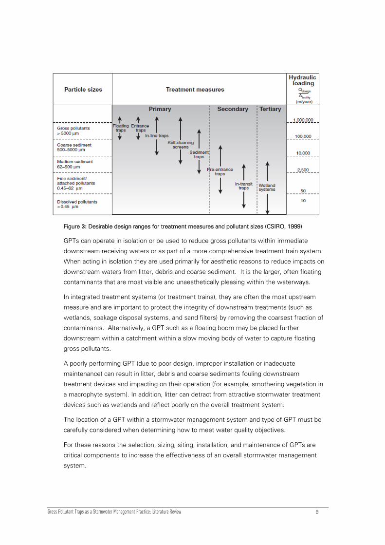
Figure 3 below illustrates the relationship between pollutant type and treatment process,
and a GPT device are generally classified as primary treatment devices, with particle
capture greater than 5000 m (5 mm) in size.
There is a clear relationship between contaminant size and the appropriate process that
can be employed to retain/remove the pollutant. By knowing the target pollutants,
appropriate treatment measures within the treatment train can be selected and properly
ordered. The figure also illustrates the approximate hydraulic loading rate for effective
operation of the various treatment measures. The hydraulic loading rate is a function of
the treatment process (screening, sedimentation, enhanced sedimentation, filtration or
biological uptake) and can be used to approximate the area required to install a device
given the design flow. This is useful to assess the space requirements for the various
treatments (CSIRO, 2006).
Gross Pollutant Traps as a Stormwater Management Practice: Literature Review 9
Figure 3: Desirable design ranges for treatment measures and pollutant sizes (CSIRO, 1999)
GPTs can operate in isolation or be used to reduce gross pollutants within immediate
downstream receiving waters or as part of a more comprehensive treatment train system.
When acting in isolation they are used primarily for aesthetic reasons to reduce impacts on
downstream waters from litter, debris and coarse sediment. It is the larger, often floating
contaminants that are most visible and unaesthetically pleasing within the waterways.
In integrated treatment systems (or treatment trains), they are often the most upstream
measure and are important to protect the integrity of downstream treatments (such as
wetlands, soakage disposal systems, and sand filters) by removing the coarsest fraction of
contaminants. Alternatively, a GPT such as a floating boom may be placed further
downstream within a catchment within a slow moving body of water to capture floating
gross pollutants.
A poorly performing GPT (due to poor design, improper installation or inadequate
maintenance) can result in litter, debris and coarse sediments fouling downstream
treatment devices and impacting on their operation (for example, smothering vegetation in
a macrophyte system). In addition, litter can detract from attractive stormwater treatment
devices such as wetlands and reflect poorly on the overall treatment system.
The location of a GPT within a stormwater management system and type of GPT must be
carefully considered when determining how to meet water quality objectives.
For these reasons the selection, sizing, siting, installation, and maintenance of GPTs are
critical components to increase the effectiveness of an overall stormwater management
system.

Gross Pollutant Traps as a Stormwater Management Practice: Literature Review 10
There are also numerous stormwater treatment devices that incorporate their own GPT as
an initial treatment stage for many of the beneficial reasons outlined within this report.
However this report does not attempt to cover multi-stage devices.
3.2 General Limitations of GPTs
GPTs as a structural primary treatment device offer many environmental and aesthetic
benefits to downstream waterways provided they are correctly designed, installed, and
maintained. However, despite their benefits there remain several limitations which need
to be carefully considered before GPT’s are selected and installed. Specific limitations
applicable to the individual type of GPT are described in more detail later in this section.
Also the Device Selection Matrix included in Appendix 1 outlines some key limitations and
features associated with each device. GPT limitations are also determined by how a GPT
is used within a catchment (i.e. as a stand-alone treatment device or as a primary
treatment within a treatment train process).
General limitations with GPTs include:
Limited (if any) removal of fine sediments less than 5 mm.
Lack of maintenance significantly reduces efficiency and performance.
Difficult and expensive maintenance procedures (primarily cleaning operations)
can lead to a decline in the trap’s maintenance frequency. A poorly maintained
trap will reduce its pollutant trapping efficiency and also may potentially become a
source of pollutants as collected material break-down.
When trash racks reach maximum capacity debris can be remobilised.
Potential to create or increase upstream flooding if the trash rack becomes
blocked by debris and litter.
Can be visually unattractive.
Potential odours if maintenance is not regular.
Potential health risks to workers when handling pollutants.
Can be a barrier to fauna migration.
GPT performance is site specific and affected by rainfall, runoff and wind – eg
higher infiltration rates reduce surface water discharge and hence the potential
for gross pollutant transport. Wind and litter drop by people also affect the extent
of accumulated pollutants.
GPT performance is directly related to the connectivity runoff pathways of the
stormwater systems entering the GPT.

Gross Pollutant Traps as a Stormwater Management Practice: Literature Review 11
There is little information collected confirming the performance of most trapping
systems in the field. Removal efficiencies to date are often based on tests of
scaled models in the laboratory (often with ‚synthetic litter‛) or limited field
testing. In addition, most gross pollutants cannot be sampled by traditional
automatic samplers and have not been included in studies evaluating the impact
of stormwater runoff on receiving waters.
3.3 Structural and Non-Structural Methods
Methods for reducing gross pollutants in urban waterways can be grouped into two
categories (Cooperative Research Centre for Catchment Hydrology, Stormwater Gross
Pollutants 1997):
Structural methods are traps placed in catchpits and gutters, or installed inside
stormwater channels to separate and contain gross pollutants, and
Non-structural methods involve changing the attitudes and actions of the
community (including business, industry and residents) through education, and
waste management programmes.
This chapter describes the structural methods commonly used for reducing gross
pollutants, known as Gross Pollutant Traps (GPTs).
3.4 GPT Treatment Mechanisms and Types
There are a wide variety of GPTs available, with varying treatment mechanisms, size,
operational requirements, cost, and trapping performance. Due to the range of techniques
available, there are no standard treatment parameters that all GPTs meet.
The extent of pollutants retained by a five millimetre mesh screen (typically used for gross
pollutant capture) can vary considerably as the set mesh size clogs and catches smaller
particles. In addition to this, sediments attached to litter and debris may also be captured
as a gross pollutant.
There are a large number of proprietary GPT devices available on the market, and this
report does not cover every variant, but instead addresses GPTs generically and provides
suitable selection criteria so that individual devices can be evaluated. Also, many drainage
inlets (e.g. catchpits and pipe entry screens) have some gross pollutant capture ability but
these are not specifically considered here. In many cases their gross pollutant capture is
aimed at avoidance of downstream system blockage rather than achieving optimal gross
pollutant removal.
GPTs are continuously being developed and modified as suppliers research the operation
of their traps and respond to treatment requirements. There is generally a shortage of field

Gross Pollutant Traps as a Stormwater Management Practice: Literature Review 12
data relating to the actual trapping performance of the various methods, making the
accuracy of treatment comparisons difficult.
For all types of GPTs, a poorly maintained device can hold gross pollutants for some time,
during which some types of GPTs can transform collected contaminants into more bio-
available forms. Small flows through the collected pollutants can then leach transformed
pollutants downstream, where they can be detrimental, in some cases causing more
problems than if a GPT was not installed.
Figure 4 below shows diagrammatically how these various pollutant removal processes are
used to target specific particle sizes.
Figure 4: Typical pollutants and treatment processes (CSIRO, 1999)
The different types of GPTs available generally fall under one of the following four
categories (CSIRO Urban Stormwater 2006):
Drainage entrance treatments: grate entrance systems, side entry catchpit traps
and gully pit traps
Direct screening devices: litter collection baskets, release nets, trash racks, return
flow litter baskets, and channel nets
Floating traps: flexible floating booms, floating debris traps
Non-clogging screens: circular and downwardly inclined screens
Sediment traps: sediment settling basins and ponds, circular settling tanks,
hydrodynamic separators.
Commonly used gross pollutant trap systems which are currently available for Auckland
region applications, range from at-source treatment for the upper reaches of the
Gross Pollutant Traps as a Stormwater Management Practice: Literature Review 13
catchment (e.g. side entry pit traps) to those intended for slow-moving waterways further
down the catchment (e.g. litter booms).
It should be noted that several of the devices detailed in this section have not yet been
installed in the Auckland region but have been used extensively overseas, significantly in
Australia.
Each device described includes an Estimated Treatment Performance Summary as a table
which considers various performances, maintenance and design considerations based on a
negligible, low, moderate, high or very high rating system. Definitions of these ratings are
included in Appendix 1 within the Device Selection Matrix.
The maintenance frequencies outlined below for each device are indicative only and based
on typical international experiences. It is recommended that each device installed within
the Auckland area be monitored and maintained initially in this manner for a period of
approximately one year to allow for site specific characteristics to be assessed. Different
land uses may require different maintenance regimes so initial monitoring and experience
will help determine an appropriate ongoing maintenance frequency which can then be
developed for the catchment to optimise maintenance efficiency. The whole of life value
for each device is critical with maintenance costs often being dramatically underestimated,
so a catchment-specific maintenance programme to optimise overall efficiency is highly
recommended.
Disclaimer
The sections below discuss the GPT types available on the market, along with their
benefits and limitations. Whilst this report may name companies and/or products, the
Auckland Council does not endorse any particular product or company. The naming of a
product or company is purely to discuss the current methods available in the market for
GPTs. It is acknowledged that other products may be available (or have become available
since the time of writing).
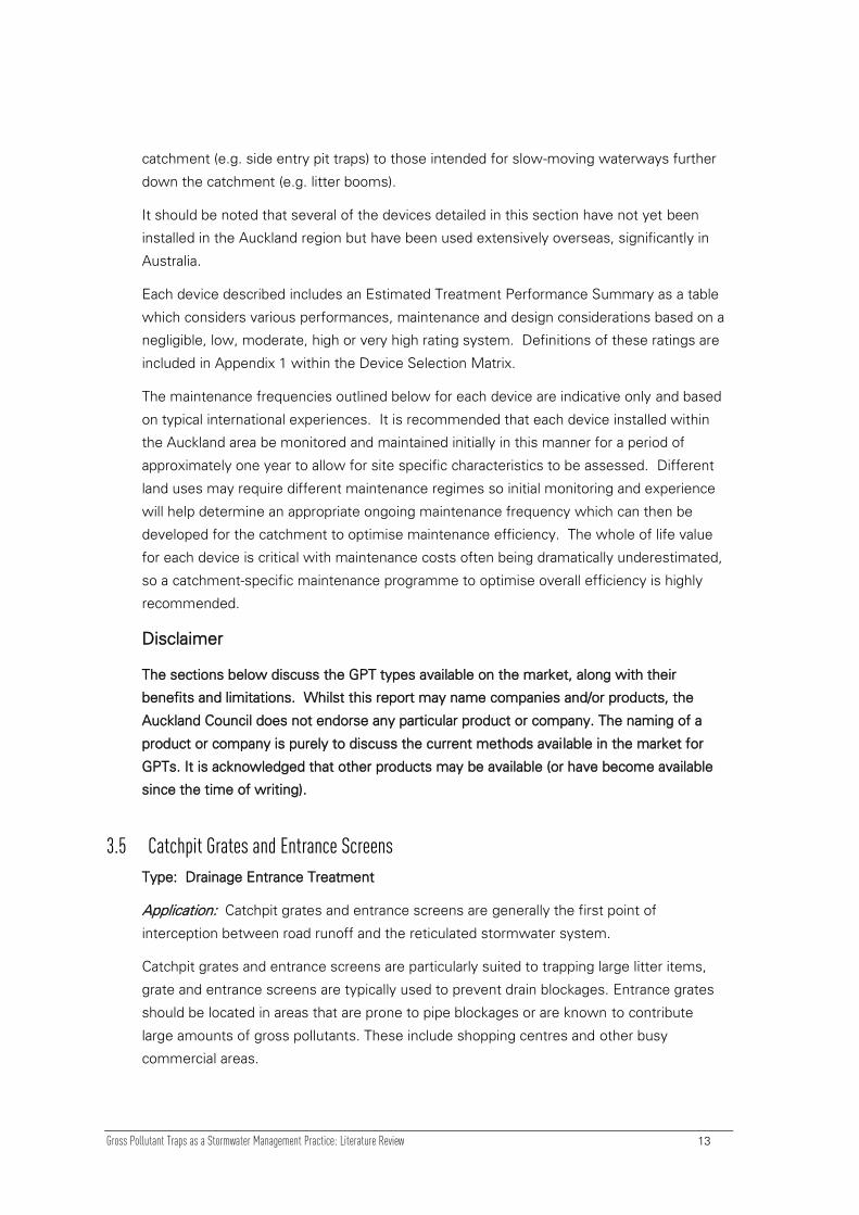
3.5 Catchpit Grates and Entrance Screens
Type: Drainage Entrance Treatment
Application: Catchpit grates and entrance screens are generally the first point of
interception between road runoff and the reticulated stormwater system.
Catchpit grates and entrance screens are particularly suited to trapping large litter items,
grate and entrance screens are typically used to prevent drain blockages. Entrance grates
should be located in areas that are prone to pipe blockages or are known to contribute
large amounts of gross pollutants. These include shopping centres and other busy
commercial areas.
Gross Pollutant Traps as a Stormwater Management Practice: Literature Review 14
Function: Grate and entrance screens consist of sturdy metal screens that cover the inlet
to the drainage network. Water passes between the screen bars, while gross pollutants
are prevented from entering. The grates are usually used on conjunction with a debris
sump.
Trapping Performance: The key function of entrance screens is to prevent pipe blockages
by excluding gross pollutants from the drainage network. Their performance efficiency
depends heavily on effective street cleaning practices—infrequent street cleaning can lead
to dispersion of trapped pollutants by either wind or traffic. In addition to this,
cesspit/catchpit filter bags can be used as a variation of this technique, and they can be
further enhanced by inclusion of a half-siphon outlet. These generally have reasonable
sediment capture but require a high level of maintenance. Moderate sediment washout
occurs due to turbulence during high flows. Litter trapping is reduced when an open
‚back-entry‛ is present.
Estimated treatment performance summary
Gross pollutants L Coarse sediment N Medium sediments N
Fine sediments Attached sediment N Dissolved N
Installation costs L Maintenance costs L/M Head requirements L
N = negligible, L= low, M=moderate, H=high, VH=very high
Reference: CSIRO, 2006
Catchpit grates and entry screens are a commonly accepted practice, and their use should
be encouraged. However as a stand-alone GPT device they perform relatively poorly,
unless their performance is enhanced by filter bags.
Maintenance:
Inspections for blocked screens may be necessary if flooding is a potential problem.
Installation costs of entrance grate and screens are low. If cleaning can be incorporated
into regular street cleaning, no additional maintenance cost need apply.
Advantages
Inexpensive and easy to install
Accepted practice
Prevent drain blockages
Suitable for targeting specific problem areas
Can be enhanced with a filter bag to increase trapping performance
Can be enhanced with a half siphon pipe arrangement to limit carry-over of
floatables and avoid pipe blockages
Gross Pollutant Traps as a Stormwater Management Practice: Literature Review 15
Can be enhanced with a screen (eg Tetra-Trap) to increase performance
Limitations
Only separates out larger gross pollutants
Relies on effective street cleaning for effective pollutant removal
Localised flooding can occur if blocked
Seasonal issues such as leaf accumulation can cause blockage
Potential for litter and solids wash-out
Smaller gross pollutants may be pushed through the grate by stormwater flow or
traffic.
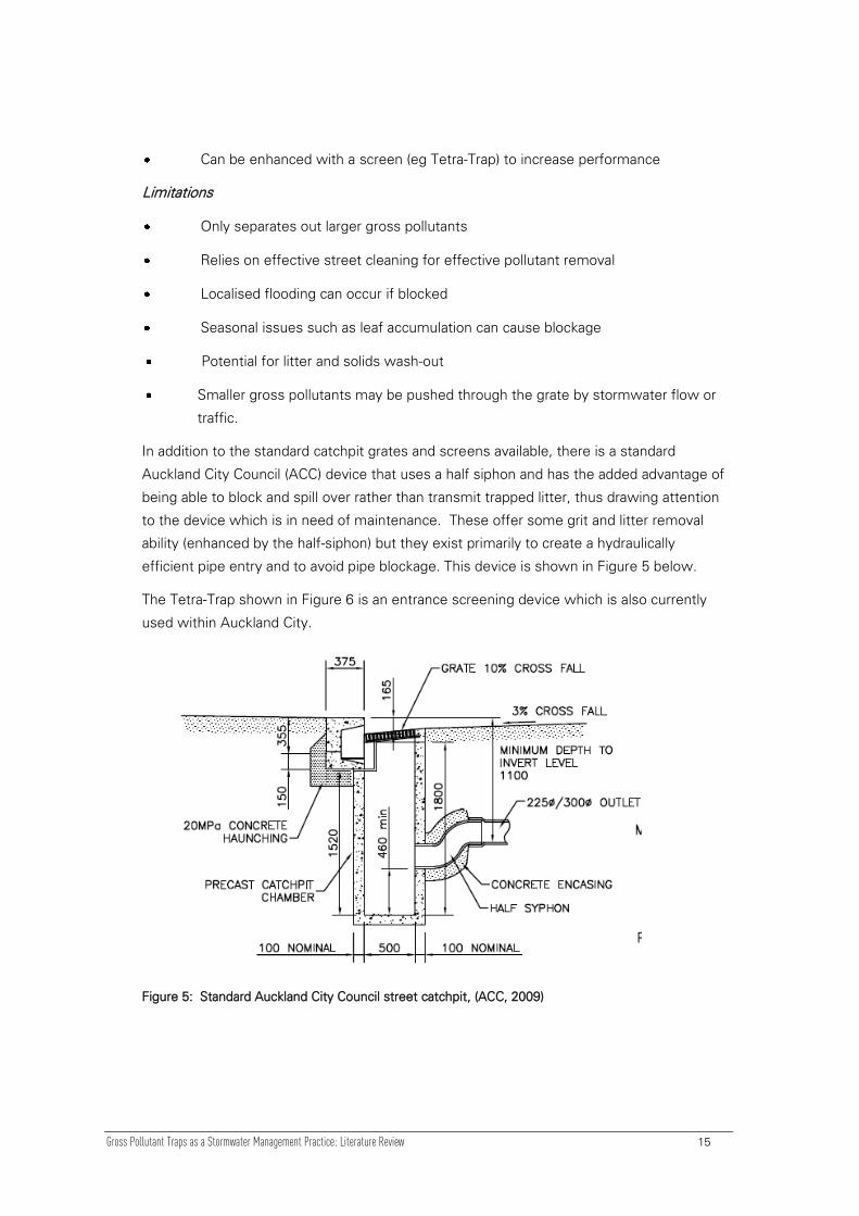
In addition to the standard catchpit grates and screens available, there is a standard
Auckland City Council (ACC) device that uses a half siphon and has the added advantage of
being able to block and spill over rather than transmit trapped litter, thus drawing attention
to the device which is in need of maintenance. These offer some grit and litter removal
ability (enhanced by the half-siphon) but they exist primarily to create a hydraulically
efficient pipe entry and to avoid pipe blockage. This device is shown in Figure 5 below.
The Tetra-Trap shown in Figure 6 is an entrance screening device which is also currently
used within Auckland City.
Figure 5: Standard Auckland City Council street catchpit, (ACC, 2009)

Gross Pollutant Traps as a Stormwater Management Practice: Literature Review 16
Figure 6: Tetra-Trap Stormwater Catchpit Device (Auckland City Transport)
3.6 Side Entry Pit Trap (SEPT)
Type: Drainage Entrance Treatment
Application: Side Entry Pit Traps (SEPTs) are used within a stormwater network where
kerb and channel and gutters exist. SEPTs may also be referred to in New Zealand as a
Catchpit Filter System (CFS) which takes the form of a fine-mesh filter bag that is inserted
inside a standard catchpit. They are often used at target areas such as shopping malls,
schools and car parks. Contributing catchments are generally less than 1 hectare.
Function: Side Entry Pit Traps (SEPTs) are baskets within a pit (much like a catchpit
arrangement) that are placed in the entrance to stormwater pipes from the roadside kerb
and channel. The baskets are fitted below the invert of the kerb and channel, inside
catchpits. Stormwater passes through the baskets to the stormwater pipe and material
larger than the basket mesh size (5-20 mm) is retained. The traps are installed with a
Gross Pollutant Traps as a Stormwater Management Practice: Literature Review 17
space at the rear of the pit to provide a flow path for high flows. When the basket pores
are blocked or during high flows, water is discharged over the rear of the basket.
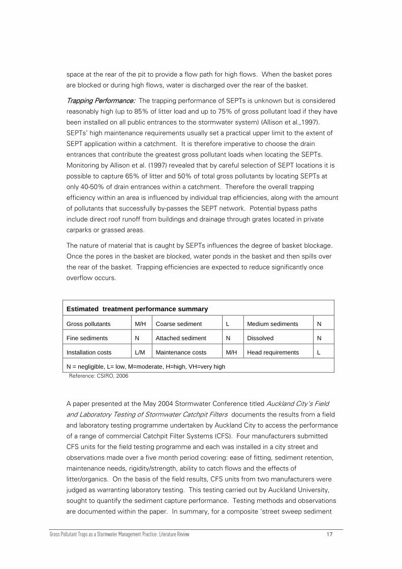
Trapping Performance: The trapping performance of SEPTs is unknown but is considered
reasonably high (up to 85% of litter load and up to 75% of gross pollutant load if they have
been installed on all public entrances to the stormwater system) (Allison et al.,1997).
SEPTs’ high maintenance requirements usually set a practical upper limit to the extent of
SEPT application within a catchment. It is therefore imperative to choose the drain
entrances that contribute the greatest gross pollutant loads when locating the SEPTs.
Monitoring by Allison et al. (1997) revealed that by careful selection of SEPT locations it is
possible to capture 65% of litter and 50% of total gross pollutants by locating SEPTs at
only 40-50% of drain entrances within a catchment. Therefore the overall trapping
efficiency within an area is influenced by individual trap efficiencies, along with the amount
of pollutants that successfully by-passes the SEPT network. Potential bypass paths
include direct roof runoff from buildings and drainage through grates located in private
carparks or grassed areas.
The nature of material that is caught by SEPTs influences the degree of basket blockage.
Once the pores in the basket are blocked, water ponds in the basket and then spills over
the rear of the basket. Trapping efficiencies are expected to reduce significantly once
overflow occurs.
Estimated treatment performance summary
Gross pollutants M/H Coarse sediment L Medium sediments N
Fine sediments N Attached sediment N Dissolved N
Installation costs L/M Maintenance costs M/H Head requirements L
N = negligible, L= low, M=moderate, H=high, VH=very high
Reference: CSIRO, 2006
A paper presented at the May 2004 Stormwater Conference titled Auckland City’s Field
and Laboratory Testing of Stormwater Catchpit Filters documents the results from a field
and laboratory testing programme undertaken by Auckland City to access the performance
of a range of commercial Catchpit Filter Systems (CFS). Four manufacturers submitted
CFS units for the field testing programme and each was installed in a city street and
observations made over a five month period covering: ease of fitting, sediment retention,
maintenance needs, rigidity/strength, ability to catch flows and the effects of
litter/organics. On the basis of the field results, CFS units from two manufacturers were
judged as warranting laboratory testing. This testing carried out by Auckland University,
sought to quantify the sediment capture performance. Testing methods and observations
are documented within the paper. In summary, for a composite ‘street sweep sediment

Gross Pollutant Traps as a Stormwater Management Practice: Literature Review 18
sample’, the CFS units were found to capture between 78% to 97% of the sediments
entering the catchpit (Butler et al., 2004)
Maintenance: Material remains in the basket until maintenance is carried out either
manually or using a large diameter vacuum device. The traps are intended to be cleaned
every four to six weeks. Typically a team of two operators and one truck can clean up to
50 SEPTs a day (CSIRO, 2006).
Advantages
Prevents drain blockages
Suitable for targeting specific problem areas
Can be retrofitted into existing drainage systems
Can be used as a pre treatment for other measures
Low head requirements thus are suitable for many low lying situations
Minimal visual impact as SEPTs are installed underground
Relatively cheap and easy to install compared to some alternative options
Limitations
Distributed SEPTS make maintenance intensive
Requires regular maintenance due to the limited holding capacity
A vacuum device may not unclog pores in the basket. Back flushing would be
needed to do this.
Previously caught material may be re-suspended if overtopping occurs
Only suitable for road entrant/kerb and channel installations
Frequently requires traffic control during maintenance
Provides a beneficial function but are generally not sufficient as a standalone
device
Different designs include steel and plastic baskets, pore size and cleaning technique
(manual or automated). Plastic baskets have the advantage of easier cleaning as material
has a lesser tendency to entangle with mesh but they require vacuum plant rather than
manual labour for cleaning because they are fixed inside the pits (CSIRO, 2006).

Gross Pollutant Traps as a Stormwater Management Practice: Literature Review 19
.
Figure 7: Side Entry Pit Trap – side elevation (CSIRO, 2006)
3.7 Baffled Pits (Trapped Street Gullies)
Type: Drainage Entrance Treatment
Application: Installations to date have been limited and they were originally designed for
providing odour control for combined sewers but have more recently been recognised for
their pollutant retention capabilities. They generally are used in catchments 0.1 – 2
hectares.
Function: Baffled Pits (or Trapped Street Gullies) are modified stormwater pits (with
baffles installed) used to retain sediments and floating material from road runoff. Baffle
plates fitted in the drainage pits are used to facilitate the settlement of heavy sediments
and containment of floating debris in the pit. Designs have been modified after hydraulic
modelling to improve the retention capabilities by minimising velocities.
Maintenance: An appropriate access chamber for inspection and cleaning is needed for
this device. The contents of the pit are removed with a large diameter vacuum device
during maintenance which is recommended every three weeks.
Trapping Performance: Baffled pits are best suited to trapping highly buoyant
contaminants or heavy, fast settling solids. Conventional baffled pits often have limited
sediment retention capacity due to the turbulence associated with inflows. Desorption of
pollutants under anaerobic conditions has also been reported. As a consequence,
conventional baffled pits can discharge pollutants during and following large storm events,
particularly if maintenance is poor. Recent design developments are starting to address
some of these concerns. On average, the estimated efficiency for gross pollutant removal
is considered low to moderate.

Gross Pollutant Traps as a Stormwater Management Practice: Literature Review 20
Estimated treatment performance summary
Gross pollutants L Coarse sediment M Medium sediments L/M
Fine sediments L Attached sediment N Dissolved N
Installation costs L/M Maintenance costs L/M Head requirements L
N = negligible, L= low, M=moderate, H=high, VH=very high
Reference: CSIRO, 2006
Advantages
Can be used as a pre-treatment for other measures
Can be retrofitted into existing drainage systems, particularly on roads with high
traffic volumes
Minimal visual impact as they are installed underground
Can prevent odours exiting the drain
Low head requirements make Baffled Pits good for many low lying situations
Limitations
Some designs have a potential to re-suspend sediments
Potential release of nutrients and heavy metals from sediments
Potential for scouring of collected pollutants during high flows
Requires regular maintenance due to the trap’s limited holding capacity
Poor retention of material that is entrained in the flow
Reduces or eliminates air supply to the drainage network downstream of the pit
Large retention pit capacity is required for effective pollutant removal

Gross Pollutant Traps as a Stormwater Management Practice: Literature Review 21
Figure 8: Section view of a baffled pit (CSIRO, 2006)
3.8 Trash Racks
Type: Direct Screening Device
Application: Trash racks are generally installed in stormwater open channels for
catchments 20 - 500 hectares in size and can be either inline or offline.
Function: Trash Racks intercept floating (such as bottles/cans) and submerged objects
(such as plastic bags). They generally consist of vertical steel bars (typically spaced 40 –
100 mm apart) and are manually cleaned. Trash racks provide a physical barrier that water
must pass through and material larger than the bar spacing is retained. As material builds
up behind the trash rack finer material also accumulates.
Maintenance: It is impractical and unsafe to clean trash racks during storms, therefore it is
imperative for trash racks to be self cleansing for at least the duration of a storm or
sufficiently sized to accommodate the expected load in a typical storm event.
Maintenance of trash racks is generally done manually on an as needed basis. Monthly is
recommended.
Trapping Performance: The estimated efficiency for gross pollutant removal is considered
low to moderate. Limited performance data suggests trapping efficiencies between 5 –
14% for floating items. The main disadvantage of a trash rack is its inability to self
cleanse. Although trash racks are designed to continue operating while partially blocked,
trash rack overtopping is common. There have been numerous attempts to develop a self
cleansing trash rack including widening the bar spacing and angling the screen to the flow,
angling the rack across the channel bed, using horizontal bars along the rack, and vibrating
the trash racks. Designs have also pushed gross pollutants along the racks to a collection
point. All results have shown minor, if any improvements in the field.

Gross Pollutant Traps as a Stormwater Management Practice: Literature Review 22
Estimated treatment performance summary
Gross pollutants L Coarse sediment L/N Medium sediments L/N
Fine sediments N Attached sediment N Dissolved N
Installation costs L Maintenance costs L/M Head requirements L/M
N = negligible, L= low, M=moderate, H=high, VH=very high
Reference: CSIRO, 2006
Advantages
May be used to trap litter upstream of other treatment measures or waterways
Can be retrofitted into existing drainage systems
Collects litter at a single location rather than over a large area
Simple to construct
Limitations
The backwater behind a blocked trash rack can cause upstream flooding, reduce
flow velocities near the rack and allow sediments to settle which further
contributes to blocking.
Previously caught material may be released if overtopping occurs
Difficult to maintain and requires manual maintenance
Appearance of the rack and trapped litter can be obtrusive
Material may be re-suspended due to tidal effects in tidal channels
Moderate to high head requirements limit the use of Trash Racks for some
applications.
3.9 Litter Control Devices (LCD)
Type: Direct Screening Device
Application: Litter Control Devices are generally located in pits within the piped drainage
network where the catchment area ranges from 2 to 150 ha.
Function: LCDs consist of steel frames that support metal baskets which are
approximately 1 m3 in size. The baskets sit below the invert of the inlet pipe and water
drops into the baskets (that have 30 mm diameter pressed holes in the sides) and flows
out through the holes in the baskets. Large material (greater than 30 mm pore size) is

Gross Pollutant Traps as a Stormwater Management Practice: Literature Review 23
retained in the basket and as it builds up, it reduces the pore sizes offered to the incoming
flow allowing smaller material to be caught.
Maintenance: Regular (weekly) cleaning is recommended. Maintenance involves lifting
the LCD directly onto disposal vehicles with modified 5 tonne cranes. Alternatively the
baskets may be emptied with a vacuum plant. To clean one trap it generally takes 20-40
minutes.
Trapping Performance: LCDs have been reported to have varying effectiveness for
trapping gross pollutants, but have been reported on average with moderate to high
efficiencies of 80 – 85%, but as low as 35% for larger storm events. Effectiveness is
highly dependent on cleaning frequency. Problems with floating materials in tidal areas
and high discharges are cited as possible reasons for material passing the traps. Inclined
trash racks have also been used at the downstream end of particular LCDs to collect
material scoured from baskets.
Estimated treatment performance summary
Gross pollutants M/H Coarse sediment L/N Medium sediments N
Fine sediments N Attached sediment N Dissolved N
Installation costs M/H Maintenance costs M/H Head requirements M/H
N = negligible, L= low, M=moderate, H=high, VH=very high
Reference: CSIRO, 2006
Advantages
Can be retrofitted into existing drainage systems
Potentially useful in areas with high litter loads
Easy to maintain
Can be used as pre treatment for other measures
Minimal visual impact as installed underground
Limitations
The traps require approximately 1m drop in the channel bed from the inlet to
outlet to accommodate the basket. This limits their applicability in low lying
areas, and in retrofit situations.
Can cause upstream flooding if blocked
Hydraulic head loss occurs particularly for baskets installed in the base of pits
Presents a possible source of odours and health risk to cleaning crews

Gross Pollutant Traps as a Stormwater Management Practice: Literature Review 24
Previously caught material may be re-suspended if overtopping occurs
Problems with floating materials in tidal areas and high discharges are cited as
possible reasons for material passing the traps
Some tests show that only a small quantity of gross pollutants remain after large
flow events
Figure 9: Litter collection device (CSIRO, 2006)
3.10 Fixed Trash Traps
Type: Direct Screening Device
NOTE: This device is referred as Gross Pollutant Trap in CSIRO, 2006.
Application: Fixed trash traps are generally installed within a stormwater channel or
waterway for catchments 5 – 5,000 hectares in size. Fixed trash traps are of considerable
size and consequently are best suited to developing areas where land can be set aside for
construction which is generally on the edges of urban areas.
Function: Fixed trash traps are in-transit pollution traps intended to remove litter, debris
and coarse sediments. Fixed trash traps have evolved from sedimentation basins, and
generally consist of a large concrete-lined wet basin upstream of a weir and trash rack.
The philosophy behind fixed trash traps is to decrease flow velocities sufficiently so that
coarse sediments settle to the bottom. This is achieved by increasing the width and depth
of the channel in the trap basin. The trash rack on the downstream end of the basin
(usually constructed of vertical steel bars) is intended to collect floating and submerged
debris in the same way as conventional trash racks.
Two types of fixed trash traps have evolved – major and minor traps. Major fixed trash
traps are open and intended to be located in large floodway’s and treat medium to large
flows. Minor fixed trash traps are closed and intended to be placed at features within the
drainage system (heads of floodway’s, junctions of stormwater pipes and major water
bodies) but the principles of operation are the same for both traps. Design criteria for the
Gross Pollutant Traps as a Stormwater Management Practice: Literature Review 25
sizing of the sediment basin in a fixed trash traps have been set according to the potential
impact that sediments pose on downstream water bodies.
Maintenance: Manual litter removal is generally carried out monthly. Additional
maintenance involves dewatering the wet basin and using a backhoe to remove
sediments. This is generally carried out six monthly.
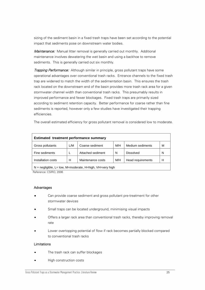
Trapping Performance: Although similar in principle, gross pollutant traps have some
operational advantages over conventional trash racks. Entrance channels to the fixed trash
trap are widened to match the width of the sedimentation basin. This ensures the trash
rack located on the downstream end of the basin provides more trash rack area for a given
stormwater channel width than conventional trash racks. This presumably results in
improved performance and fewer blockages. Fixed trash traps are primarily sized
according to sediment retention capacity. Better performance for coarse rather than fine
sediments is reported, however only a few studies have investigated their trapping
efficiencies.
The overall estimated efficiency for gross pollutant removal is considered low to moderate.
Estimated treatment performance summary
Gross pollutants L/M Coarse sediment M/H Medium sediments M
Fine sediments L Attached sediment N Dissolved N
Installation costs H Maintenance costs M/H Head requirements H
N = negligible, L= low, M=moderate, H=high, VH=very high
Reference: CSIRO, 2006
Advantages
Can provide coarse sediment and gross pollutant pre-treatment for other
stormwater devices
Small traps can be located underground, minimising visual impacts
Offers a larger rack area than conventional trash racks, thereby improving removal
rate
Lower overtopping potential of flow if rack becomes partially blocked compared
to conventional trash racks
Limitations
The trash rack can suffer blockages
High construction costs

Gross Pollutant Traps as a Stormwater Management Practice: Literature Review 26
Difficult and expensive to clean
Hydraulic head loss occurs through the trash rack
Can cause upstream flooding during trash rack blockages
The appearance of the rack and trapped litter can be aesthetically displeasing
Potential breakdown of collected pollutants in wet sump (basin)
Retrofitting can be difficult due to land and topographic requirements
Previously caught material may be re-suspended if overtopping occurs
A moderate to high amount of head is also required which limits their use for
some applications.
Figure 10: Fixed Trash Trap (CSIRO, 2006)
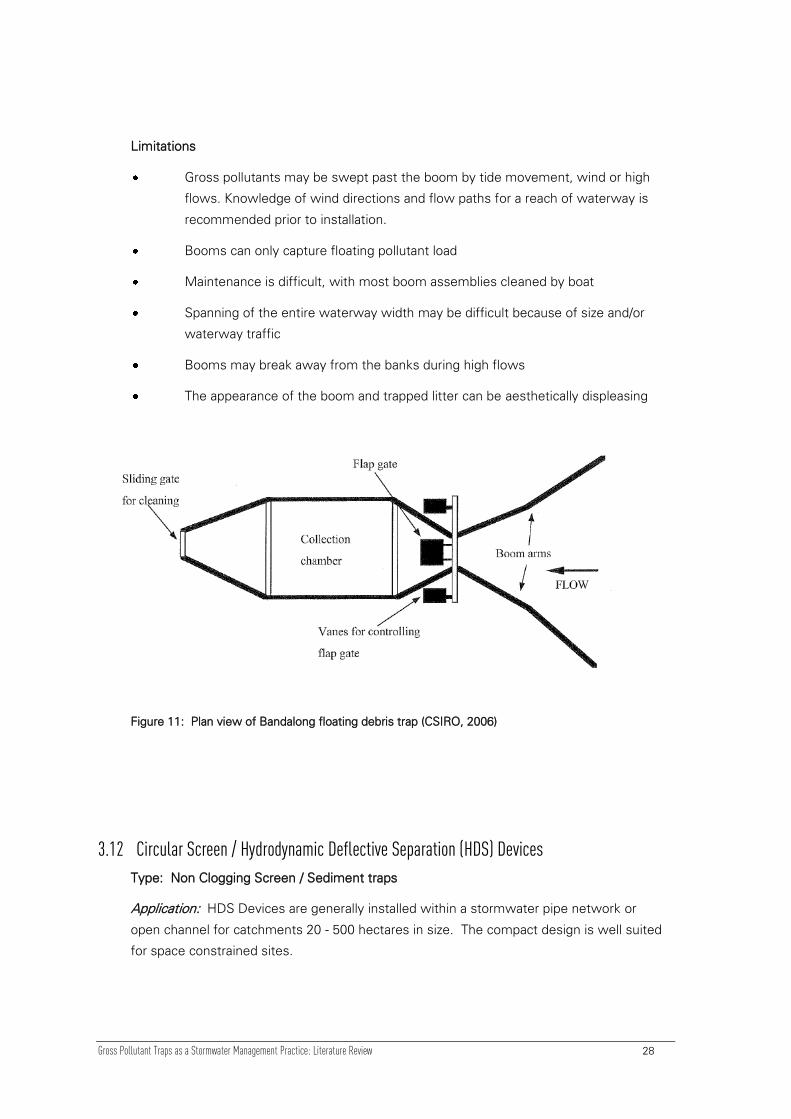
3.11 Booms and Floating Traps
Type: Floating Traps
Application: Litter booms and floating traps are best suited for very slow moving waters
and perform best with floating objects such as plastic bottles and polystyrene. Catchment
areas are generally greater than 250 ha.
Function: Litter booms are constructed by stringing partly submerged floating booms
across waterways. The boom intercepts and collects floating objects. The performance of
any boom is greatly influenced by the flow conditions of the waterway.
More recently Floating Debris Traps (FDTs) have evolved from booms and have enhanced
retention of captured material and an improved cleaning method. The traps use floating
polyethylene boom arms with fitted skirts to deflect floating debris through a flap gate into
a storage compartment. The flap gate is intended to prevent collected floatables escaping

Gross Pollutant Traps as a Stormwater Management Practice: Literature Review 27
with changed wind or tidal conditions. A sliding gate on the downstream end of the trap
provides an improved cleaning method. As the grate is raised during cleaning; material
flows out of the trap and into a collection basket that is located downstream of the trap.
Maintenance: Litter booms generally require manual cleaning, performed by retrieving
collected trash from within the boom with a trench digger or by using boat and pitch forks.
To improve this operation for small booms, they can be pulled to one bank and material
can be accessed manually from land. Booms angled across the flow are intended to
transfer collected material to a collection area that is accessible from land. Cleaning is
usually on demand, but fortnightly – monthly is recommended.
Trapping Performance: During high flows the trapping efficiency of litter booms is greatly
reduced because material is forced over and under the boom, or the boom may break from
the banks. The litter retention properties of booms can be enhanced by angling booms
across to the current away from high velocity areas and by using mesh skirts. However
high flow problems still persist.
The floating boom is only effective in retaining gross pollutants that float. This represents
less than 20% of litter and 10% of vegetation which suggests a limited performance for
floating boom applications. However, despite the inefficiencies with booms (during high
flows and for submerged material) they have been reported to trap large quantities of
gross pollutants, particularly the large highly-visible litter component that the general public
tend to be most aware of.
Although there is little data regarding the trapping efficiency of floating debris traps, it is
likely that they experience similar problems to floating booms (high flow problems and
wind distributing gross pollutants away from the traps).
Estimated treatment performance summary
Gross pollutants L Coarse sediment N Medium sediments N
Fine sediments N Attached sediment N Dissolved N
Installation costs L Maintenance costs M Head requirements L
N = negligible, L= low, M=moderate, H=high, VH=very high
Reference: CSIRO, 2006
Advantages
Enhances aesthetics and recreational potential of downstream waterways
Mobile and may be appropriate for retrofitting into existing areas
Collects litter at a single location rather than numerous sites over a large area
Able to rise and fall with changes in flow or tide
Gross Pollutant Traps as a Stormwater Management Practice: Literature Review 28
Limitations
Gross pollutants may be swept past the boom by tide movement, wind or high
flows. Knowledge of wind directions and flow paths for a reach of waterway is
recommended prior to installation.
Booms can only capture floating pollutant load
Maintenance is difficult, with most boom assemblies cleaned by boat
Spanning of the entire waterway width may be difficult because of size and/or
waterway traffic
Booms may break away from the banks during high flows
The appearance of the boom and trapped litter can be aesthetically displeasing
Figure 11: Plan view of Bandalong floating debris trap (CSIRO, 2006)
3.12 Circular Screen / Hydrodynamic Deflective Separation (HDS) Devices
Type: Non Clogging Screen / Sediment traps
Application: HDS Devices are generally installed within a stormwater pipe network or
open channel for catchments 20 - 500 hectares in size. The compact design is well suited
for space constrained sites.

Gross Pollutant Traps as a Stormwater Management Practice: Literature Review 29
Function: The HDS mechanism of solid separation is by diverting the incoming flow and
associated pollutants away from the main flow stream of the pipe or waterway into a
pollutant separation and containment chamber. Solids within the separation chamber are
kept in continuous motion and are prevented from ‘blocking’ the screen. This is achieved
by a hydraulic design that ensures the tangential force exerted on an object by the circular
flow action is significantly higher than the friction caused by the centrifugal force
associated with the rotating flow in the circular chamber. Floating objects are kept in
continuous motion on the water surface while the heavier pollutants settle into a
containment sump.
The main flow in the chamber behaves in the manner of solid body rotation (forced vortex)
and consequently any object in the flow with a density greater than water will be forced
outwards and be pressed against the outer boundary of the chamber (the perforated
screen). Also objects near the screen will be influenced by the drag forces associated with
the flow component through the perforated mesh, however these are considered
negligible compared to the centrifugal forces.
A diversion structure upstream of the HDS unit acts as a bypass weir and is constructed so
that during periods of above design conditions, excess stormwater can bypass the HDS
unit. The selection of the height of the weir determines the frequency of stormwater
bypass. The height of the weir is dependent on a number of factors including the
topography of the site, depth of cover of the existing pipe and the discharge capacity of
the stormwater system. The diversion weir is typically designed to divert at least 95% of
annual discharge through the separation chamber.
Maintenance: Material that collect in the separation chamber can be removed in two
ways. The sump can be fitted with a large basket that collects sinking material and can be
lifted with a crane onto a removal truck. Alternatively the contents of the sump can be
removed with a powerful vacuum pump. A two to three monthly cleaning frequency is
recommended.
Trapping Performance: High trapping efficiencies have been recorded. During twelve
months of monitoring, practically all gross pollutants transported by the stormwater
system were trapped by the HDS unit (Allison et al. 1996). Longer term trapping rates will
be determined by the height of the bypass weir. Typical installations accommodate at
least a one in six month storm prior to overflow. This would ensure at least 95% of annual
discharge is treated, with a similar proportion of gross pollutants captured. Some
monitoring suggests a significant quantity of sediment is retained. 90% of the sediment
recovered from the collection sump was smaller than the screen mesh size. In addition,
70% retention of suspended sediment by the device was reported during the early flows
of a runoff event (Walker et al. 1999).

Gross Pollutant Traps as a Stormwater Management Practice: Literature Review 30
Figure 12: Continuous deflective separation trapping system (CSIRO, 2006)
Estimated treatment performance summary
Gross pollutants V/H Coarse sediment H Medium sediments M
Fine sediments L/M Attached sediment L Dissolved N
Installation costs H Maintenance costs M Head requirements L
N = negligible, L= low, M=moderate, H=high, VH=very high
Reference: CSIRO, 2006
It should be noted that there are several similar proprietary versions of the HDS unit
available with various features.
Advantages
Very high removal rate for gross pollutants
Low head requirements
Can be retrofitted into existing drainage systems
Minimal visual impact as typically installed underground
Traps coarse sediment, with limited fine sediment retention
Units with submerged screens also retain oils
Minimal maintenance requirements
Limitations
HDS units require a greater capital investment but are considered to provide
easier maintenance than other trapping systems.

Gross Pollutant Traps as a Stormwater Management Practice: Literature Review 31
Potentially large structure requires substantial area and depth
Potential breakdown of collected pollutants in wet sump
Potential re-suspension of sediments if design flows are exceeded

Gross Pollutant Traps as a Stormwater Management Practice: Literature Review 32
4 Considerations when selecting a GPT 4.1 Pre-requirements
Prior to the selection of an appropriate Gross Pollutant Device, the following key questions
need to be considered:
1 Is full PARC-ALW (Proposed Auckland Regional Council Air, Land and Water Plan)
compliance required and appropriate for the site?
2 Is the installation of a GPT justified at the site?
For many newly developed sites or infrastructure full ALW compliance would be required
and appropriate. Therefore the installation of a GPT in this situation would be considered a
useful primary treatment device. A GPT would be installed in conjunction with other
necessary treatment measures required to meet full ALW compliance.
For many retrofit sites, full ALW compliance may not be required. Where this is the case,
a GPT may still be justified.
It is critical to carefully consider the appropriateness of a GPT installation as a useful
installation within the treatment train of the wider catchment. In many situations GPTs
may not align well with a catchment’s specific characteristics, pollutant types, existing
treatment devices and likely maintenance regimes.
Once the need for a GPT has been established, the key considerations outlined below can
be used to help ensure the correct GPT is selected.
4.2 Treatment Performance Objectives
It is important to determine appropriate catchment-specific treatment performance
objectives for a GPT, whilst considering existing treatment devices within the wider
catchment area. It is essential that these objectives are established as part of the
conceptual design process and discussed with the client prior to commencing.
Treatment devices are generally assessed according to their trapping efficiency for each
pollutant category, so designers need to ensure each device considered is specific to the
pollutant profile of the catchment. Some GPT devices will claim to target smaller sediment
and pollutants, however designers are recommended to confirm the proven performance
of each device considered. Gross pollutant capture generally includes trash, litter and
vegetation larger than 5 mm.
Gross Pollutant Traps as a Stormwater Management Practice: Literature Review 33
4.3 Design Flows
Catchment specifics such as size, rainfall/runoff patterns, infiltration rates and the
connectivity of stormwater systems will alter the extent and type of gross pollutants able
to be captured within any catchment. These factors will also affect the design flow
selection for a particular catchment. The design flow is maximum flow rate at which a
treatment device is designed to operate effectively.
A whole of life assessment must be carried out to evaluate the merits of increasing the
volume of runoff treated by the device (design flow), whilst considering environmental and
aesthetic benefits to receiving waters and additional capital and operational costs.
Determining the design flow is generally a trade-off between cost and space requirements
of the device and the volume of water that could potentially bypass the treatment device
and avoid treatment.
4.4 Flood Capacity
A high flow bypass is generally designed into treatment devices for protection from large
flood flows that could damage the device or scour and transport previously collected
pollutants downstream. Again, a close look at the proven performance of high flow
bypasses in the various devices considered is recommended.
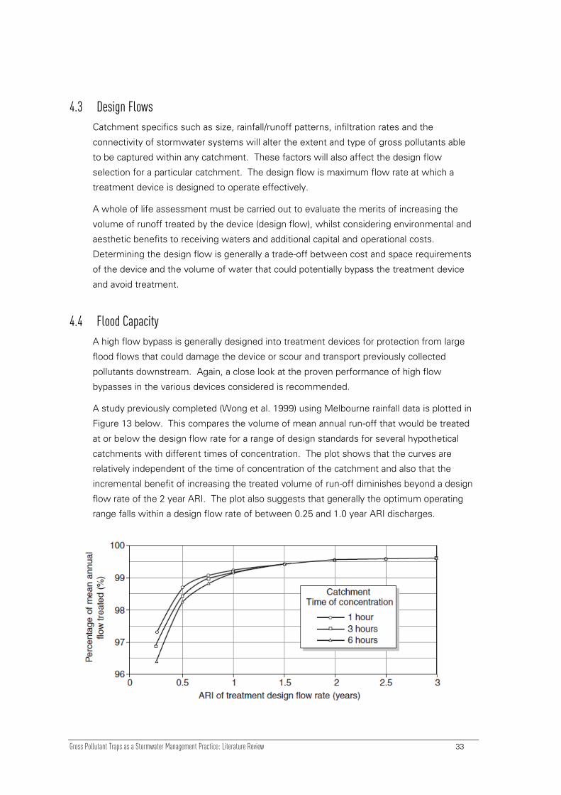
A study previously completed (Wong et al. 1999) using Melbourne rainfall data is plotted in
Figure 13 below. This compares the volume of mean annual run-off that would be treated
at or below the design flow rate for a range of design standards for several hypothetical
catchments with different times of concentration. The plot shows that the curves are
relatively independent of the time of concentration of the catchment and also that the
incremental benefit of increasing the treated volume of run-off diminishes beyond a design
flow rate of the 2 year ARI. The plot also suggests that generally the optimum operating
range falls within a design flow rate of between 0.25 and 1.0 year ARI discharges.
Gross Pollutant Traps as a Stormwater Management Practice: Literature Review 34
Figure 13: Treatment design flows plotted against the percentage of mean annual flow treated for
the Melbourne region (Wong 1999)
4.5 Trapped Pollutant Storage
Trapped pollutants are held in a wet sump, in baskets, nets or behind screens that are free
draining. The GPT needs to be designed so that it prevents re-suspension of captured
contaminants during flows in excess of the design ARI. The most efficient GPTs are
configured so that pollutants accumulate in a location that is not affected by high flows.
The continuous wet conditions in a pollutant containment sump and possibly limited turn
over, mixing or aeration can lead to organic material decomposition, with depleted oxygen
levels creating severe reducing conditions. Under these conditions, collected pollutants
can be transformed from a relatively innocuous state to highly bio-available forms that are
then released to downstream waters with any through-flow.
Therefore, when installing as a stand-alone GPT (i.e. without downstream treatment
measures) the impact on downstream waterways from the release of potential pollutants
from wet sumps should be considered. If necessary, GPT type or configuration needs to
be reviewed.
4.6 Maintenance Requirements
The main environmental issues with GPTs are associated with:
Long-term storage of pollutants that may be remobilised or cause odour;
Limitations on the disposal of the trapped material.
A poorly maintained treatment device may not only perform badly, it may become a flood
hazard or a source of pollution itself. Maintenance is the most commonly overlooked
aspect of GPT selection, yet it is one of the most important for gross pollutant reduction.
GPT operation and maintenance requirements vary widely and the following issues with
regard to maintainability and operability should be considered when selecting design
objectives and targets:
Access to the treatment site (i.e. by vehicle);
Ease and frequency of maintenance;
Availability of spare parts and service;
Disposal of waste.
The ease of maintenance relates to the systems and equipment required to clean a GPT.
Cleaning systems range from:
Manual handling of collected pollutants;
Gross Pollutant Traps as a Stormwater Management Practice: Literature Review 35
Vacuuming collected pollutants;
Using a crane to retrieve collected pollutants from a basket or net; or
Using large excavators to remove pollutants.
The design of any removable sump or basket collection system must ensure that floatable
contaminants do not overspill the basket during lifting or clean out operations.
It is important that an assessment of the catchment pollutant load be undertaken in winter
months to determine the likely pollutant ‘wash off’ and collection load. This load can be
used to determine the holding capacity (or pollutant storage volume) required of the GPT
for the catchment. This knowledge can also be applied in combination with winter climatic
conditions to determine the frequency of clean out procedures required to ensure the trap
is working efficiently.
4.7 Site Suitability Assessment
The choice of GPT location has a big influence on cost, treatment effectiveness,
maintainability and overall device sustainability.
All potential sites for a GPT installation within the catchment need to be identified, whilst
considering the specific characteristics and constraints of each location.
GPT location is affected by many factors. Initially the adoption of an ‘outlet’ or ‘distributed’
approach needs to be determined. The traditional outlet approach involves constructing a
single large treatment device at the catchment’s outlet.
This single site approach offers obvious maintenance advantages; it has the disadvantage
of needing to treat larger volumes of water at a location often a considerable distance from
the pollutant’s source.
An alternative is the distributed approach where a number of smaller and potentially
different GPT treatments are installed throughout the catchment. This offers many
advantages including:
Improved protection: water quality protection may be distributed along a greater
length of waterway
Localised treatment: particular treatments may be specifically targeted at highly
polluted sites
Improved removal efficiencies: distributed treatments are typically located in areas
of lower flow. Lower flow velocities and volumes and high pollutant
concentrations in stormwater at these sites lead to higher operating efficiencies
Staged implementation: individual sites may be brought into operation at different
stages

Gross Pollutant Traps as a Stormwater Management Practice: Literature Review 36
The characteristics of a particular site can limit the choice of treatment measures suited to
the area. Two broad site constraint categories exist - physical and social.
Physical site constraints can make construction difficult or impossible and maintenance
expensive, for example:
Topography: eg steep slopes
Soils and geology: eg erosivity, porosity, depth to bedrock or instability
Groundwater: eg geochemistry and water table depth
Space: limited open space, proximity to underground services, traffic
Nature of drainage system: open channel or piped.
Social constraints include issues of health and safety, aesthetics, and impacts on
recreational facilities, for example:
Odour problems
Visual impacts
Noise
Physical injury: eg due to unauthorised access to structures
Contamination: eg infection, poisoning or injury caused by trapped pollutants
Vermin: eg mosquitoes, rats
Many safety issues can be addressed at the treatment design stage, for example
developing specific health and safety procedures for construction and maintenance staff,
installation of warning signs, and fencing the site (CSIRO, 2006).
4.8 Cost Considerations when selecting a GPT
The costs of GPTs vary significantly based on the required size and application. This is
very much dependant on the total catchment area from which the GPT is receiving
stormwater, and the extent of gross pollutants within that catchment.
Factors which should be considered when determining installation, maintenance and
disposal costs are detailed below.
4.8.1 Installation Costs
Installation costs include the cost of supply and installation of a GPT. Variables related to
ground conditions (such as rock or groundwater conditions) or access issues may vary
construction costs significantly. Some GPT sites are inherently more simple and cost
effective than others.

Gross Pollutant Traps as a Stormwater Management Practice: Literature Review 37
To estimate the installation costs there are a number of localised issues that will need to
be considered, including:
Design flow rate and available hydraulic head;
Size and configuration of the trap (with regard to site constraints);
Safety and other construction issues.
If any of the above factors cannot be adequately satisfied by a particular trap it should be
deemed as potentially inappropriate for that location.
4.8.2 Maintenance Costs
Monitoring and maintenance costs can be more difficult to estimate than the installation
costs; however these are often the most critical variable. This is due to variances of the
techniques used, the amount of material removed and the unknown nature of the
pollutants exported from a catchment. In many cases maintenance costs are the most
significant cost of a treatment measure. It is therefore imperative to carefully consider the
maintenance requirements and estimated whole of life costs when selecting a GPT.
Allowance for any associated transport costs needs to be included, along with the time
and resources needed for data capture and storage.
One important step is to check previous installations by contacting current owners of GPTs
and asking about their annual costs. Also, product suppliers can usually supply contact and
cost information. Many vendors can also be contracted to maintain their devices which
can ensure that the maintenance costs (excluding inflation) can be determined prior to
device installation.
4.8.3 Disposal Costs
Disposal costs will vary depending on whether the collected material is retained in a wet or
dry state (i.e. either under water or left so it can drain). Handling of wet material is more
expensive and will require sealed handling vehicles.
Generally, all GPT sediment waste is considered contaminated, and gross litter requires
disposal to landfill.
Addressing the following questions will assist in determining disposal costs:
Is the material in a wet or dry state and what cost implications are there?
Are there particular hazardous materials that may be collected and will they require
special disposal requirements (e.g. contaminated waste)? If so, what cost
implications are there?
What is the expected load of material and what are the likely disposal costs?

Gross Pollutant Traps as a Stormwater Management Practice: Literature Review 38
In the event that there is no other data, the values in Table 1 below could be considered.
Table 1: Approximate Litter and Gross Pollutant Loading Rates used for Melbourne (IE Aust, 2006)
Land use Type Litter
Volume Litter Mass
Gross Pollutants
Volume Gross Pollutants
Mass
(L ha-1
yr-1
(kg ha-1
yr-1
) (L ha-1
yr-1
) (kg ha-1
yr-1
)
Commercial 210 56 530 135
Residential 50 13 280 71
Light Industrial 100 25 150 39
4.8.4 Wet versus Dry Loads
From a disposal cost sense, GPTs are grouped into two main categories according to whether a
dry or wet load is stored. This means that collected items are either stored above (dry) or below
(wet) standing water levels.
Traps that store trapped material in a dry state are generally cheaper to operate as the
collected material can be delivered to local landfill facilities without any issue.
Wet load traps are more complicated and thus more expensive to operate. They require
suction equipment for cleaning and the liquid portion is classified as toxic liquids. Disposal
is to a hazardous waste facility under often strict guidelines.
4.8.5 Whole-of-Life Costs
Whole-of-life costs are a combination of the installation and operational costs and provide
an indication of the true long-term cost of the infrastructure. It is particularly important to
consider whole-of-life costs for GPTs because maintenance costs can be significant
compared with the capital cost of installation. Consideration of asset removal and
decommissioning costs also need to be allowed for when assessing whole-of-life costs.
To determine life cycle costs, an estimated life span of the device needs to be assumed
(e.g. 20 or 25 years), or if the trap is to control pollutants during the development phase
only, it may be three to 10 years. Defining costs in terms of their Net Present Value (NPV)
is a convenient way of describing whole-of-life costs.

Gross Pollutant Traps as a Stormwater Management Practice: Literature Review 39
4.9 Device Selection Matrix
‚Device Selection Matrix‛ (Appendix 1) summarises common Primary Treatment Devices
and their attributes identified in Section 3 to assist designers with appropriate device
selection.
This Device Selection Matrix includes the selection parameters discussed in Section 4. The
following parameters are included to the matrix:
efficiency (very high – negligible)
head requirements (high-low)
construction costs (high-low)
maintenance costs (high-low)
particle size (gross pollutants, coarse, medium or fine sediments, and attached
pollutants)
The Device Selection Matrix can be used to help select appropriate GPT treatments based
on pollutant retention efficiencies, design construction and operational considerations and
costs.
Device Selection Matrix helps the designer to quickly reject the GPT techniques that have
little impact on target contaminants and specific catchment characteristics.
Having established a short list, the treatment measures should be reviewed in detail to
determine the best options. All aspects should be considered and compared including
maintainability and operability, pollutant retention, head requirements, cost and secondary
benefits. Certain treatment measures provide incidental benefits beyond the primary goal
of removing the target pollutants. Some treatment measures demonstrate the potential to
remove pollutants other than the primary targets. Some treatment types may provide
added benefits such as aiding flood control, ecological enhancement or provision of an
educational resource. Designers should, however, be careful to check proven
performance and the conditions a device was tested under when considering performance
claims over and above the primary targets.
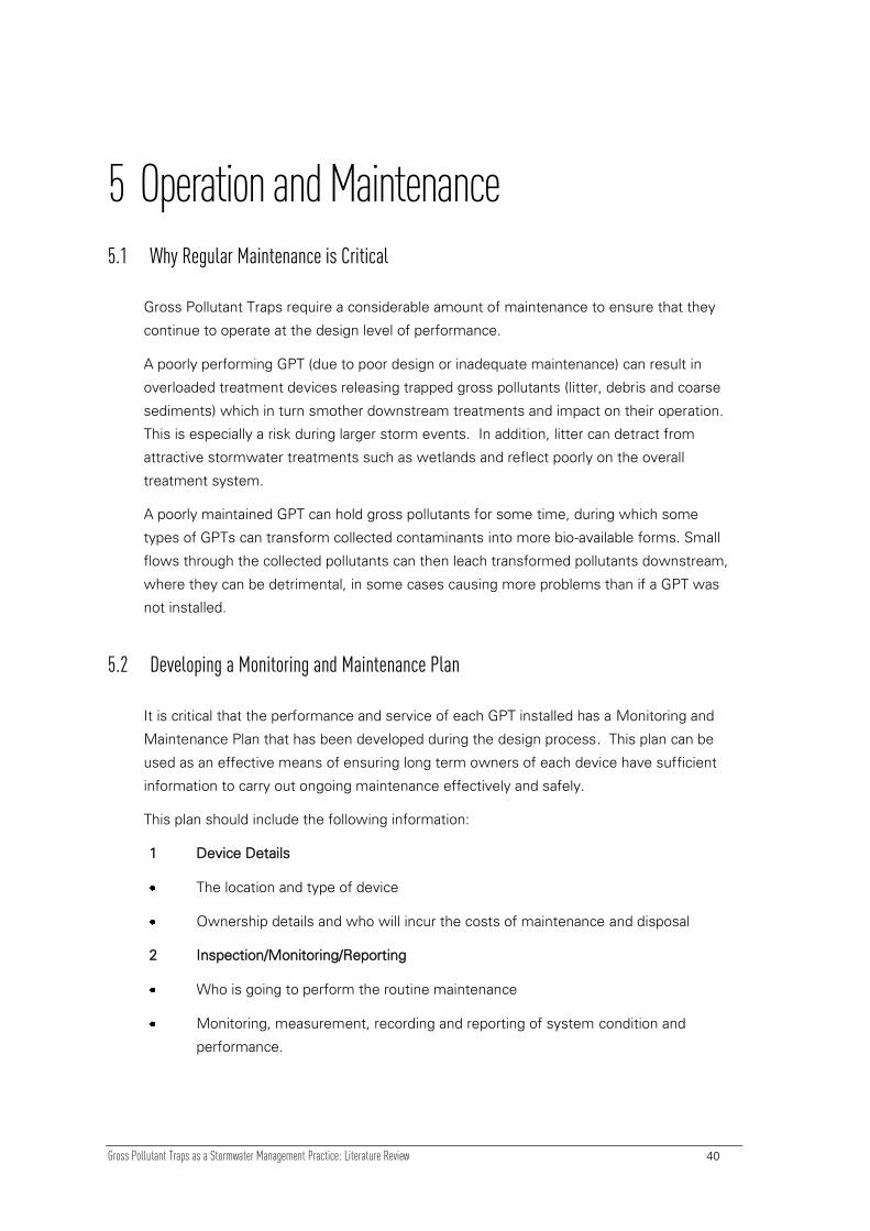
Gross Pollutant Traps as a Stormwater Management Practice: Literature Review 40
5 Operation and Maintenance 5.1 Why Regular Maintenance is Critical
Gross Pollutant Traps require a considerable amount of maintenance to ensure that they
continue to operate at the design level of performance.
A poorly performing GPT (due to poor design or inadequate maintenance) can result in
overloaded treatment devices releasing trapped gross pollutants (litter, debris and coarse
sediments) which in turn smother downstream treatments and impact on their operation.
This is especially a risk during larger storm events. In addition, litter can detract from
attractive stormwater treatments such as wetlands and reflect poorly on the overall
treatment system.
A poorly maintained GPT can hold gross pollutants for some time, during which some
types of GPTs can transform collected contaminants into more bio-available forms. Small
flows through the collected pollutants can then leach transformed pollutants downstream,
where they can be detrimental, in some cases causing more problems than if a GPT was
not installed.
5.2 Developing a Monitoring and Maintenance Plan
It is critical that the performance and service of each GPT installed has a Monitoring and
Maintenance Plan that has been developed during the design process. This plan can be
used as an effective means of ensuring long term owners of each device have sufficient
information to carry out ongoing maintenance effectively and safely.
This plan should include the following information:
1 Device Details
The location and type of device
Ownership details and who will incur the costs of maintenance and disposal
2 Inspection/Monitoring/Reporting
Who is going to perform the routine maintenance
Monitoring, measurement, recording and reporting of system condition and
performance.

Gross Pollutant Traps as a Stormwater Management Practice: Literature Review 41
3 Maintenance Requirements
What parts of the device are to be cleaned and how
Maintenance systems and equipment required
Type of maintenance and likely frequency
What, if any, machinery is required to maintain the device
What consumables/spare parts are required
Expected maintenance and inspection frequency
Expected maintenance costs or other resource requirements
Method of disposal and anticipated costs for the likely pollutant to be encountered
Access issues such as locked gates, entry through private property etc including
contact telephone numbers
Any environmental safeguards required during cleaning (eg hay bales required to
filter stormwater drained from device)
Occupational Health and Safety issues (eg is confined spaces accreditation
required to clean the device?)
Alternatives to proposed cleaning method (ie device may be cleaned by lifting out
baskets by crane or by vacuum truck)
Any other information that is important to the routine maintenance of the device
4 Contingency Plans
Details on any general and site specific contingency and emergency procedures
Details on maintenance procedures during high flow events if device is impacting
detrimentally on adjoining areas
5 Appendices
As-built plans
Manufacturers information
Resource consents
Standard forms and checklists

Gross Pollutant Traps as a Stormwater Management Practice: Literature Review 42
Maintenance personnel and asset managers should use the maintenance plan to ensure
the GPT continues to function as designed. Ongoing assessment of the condition of each
device during periods of monitoring or maintenance will allow appropriate depreciation of
the asset to be determined. An example operation and maintenance inspection form is
included in Appendix 2 of this report. These forms should be developed on a site-specific
basis as the nature and configuration of GPTs varies significantly.
5.3 Maintenance Operations
Frequency of Cleaning
The minimum level of maintenance and cleanout required to ensure the GPT system
operates as designed to maximise pollutant capture without causing adverse
environmental or hydraulic impacts, should be specified. The maintenance of GPT systems
must be able to demonstrate that captured contaminants can be stored so as not to cause
significant adverse environmental impact or nuisance (e.g. odours and putrefaction, or
flooding). The maintenance program should allow for the costs of collection, transport and
delivery of captured gross pollutants to an appropriate waste disposal facility.
The maintenance frequencies outlined for each type of device in Section 4 of this report
are indicative only based on typical international experiences. It is recommended that each
device installed within the Auckland area be monitored and maintained initially in this
manner for a period of approximately one year to allow for site specific characteristics to
be assessed. An appropriate ongoing monitoring and maintenance frequency can then be
developed for the catchment to optimise maintenance efficiency.
Timing of Cleaning
It is considered acceptable practice to disregard the need to include a flow isolation option
in the design and installation of these GPTs. All GPTs are generally cleaned during periods
of dry weather.
Method of Cleaning
Cleaning systems range from:
Manual handling of collected pollutants;
Vacuuming collected pollutants;
Using a crane to retrieve collected pollutants from a basket or net; or
Using large excavators to remove pollutants.
The maintenance/cleanout procedure to be adopted for the GPT device should utilise plant
and equipment readily available or currently in use by the maintenance contractor if
possible.

Gross Pollutant Traps as a Stormwater Management Practice: Literature Review 43
The design of any removable sump or basket collection system must ensure that floatable
contaminates do not overspill the basket during lifting or clean out operations.
Disposal of Gross Pollutants
The cost of disposal is a key maintenance consideration which is often overlooked or
underestimated. Method of disposal will depend on the pollutants and level of
contamination encountered. Silts and sediment may be considered contaminated whereas
floatable litter may be appropriately disposed of at a landfill. Disposal requirements and
costs should be confirmed and included within the Maintenance and Monitoring Plan.
All maintenance activities should be developed to ensure they require no manual handling
of collected pollutants because of safety concerns with hazardous material.
Monitoring of Gross Pollutants Collected
Where monitoring of the GPT cleanout is required, allowance should be provided in the
maintenance programme to undertake the necessary on-site or laboratory processing to
separate the contaminants into the following pollutant categories (CSIRO Urban
Stormwater 2006):
Gross pollutants: trash, litter and vegetation larger than 5 mm
Coarse sediment: contaminant particles between 5 and 0.5 mm
Medium sediment: contaminant particles between 0.5 and 0.062 mm
Fine sediment: contaminant particles smaller than 0.062 mm
Attached pollutants: those that are attached to fine sediments – specifically
nutrients, heavy metals, toxicants and hydrocarbons
Dissolved pollutants: typically nutrients, metals and salts
5.4 Check Lists
Aspects to be covered in the Construction and Maintenance Plan are described in Section
5.2 and 5.3. Appendix 2 includes checklists that can be used for selecting a GPT, design
calculation, maintenance inspection and cost association.
During the design stage the design objectives and key targets need to be achieved and
assessed and were included to the check list.
During the construction and maintenance inspections on site to ensure key aspects are
assessed and included to the check list.
Appropriate installation is critical and is often overlooked. Installations should be checked
to ensure correct construction drawings have been followed with an independent third
party inspection carried out.

Gross Pollutant Traps as a Stormwater Management Practice: Literature Review 44
Photo 1: Maintenance of a litter and sediment trap by vacuum (Department of Water 2006)
Photo 2: Maintenance using a truck mounted crane to lift sediment baskets (www.nettech.com.au)

Gross Pollutant Traps as a Stormwater Management Practice: Literature Review 45
6 Summary Gross Pollutant Traps (GPTs) are devices used for water quality control with the primary
purpose of removing gross pollutants greater than 5 mm. Some GPT’s are designed for
‚Gross Pollutants‛ such as containers, leaves, bottles and plastic bags. However, gross
pollutant also includes large particles such as gravel and particles greater than 5 mm and
GPTs may be designed to remove these eg catchpit. Smaller pollutants, such as dirt,
chemicals, heavy metals and bacteria are not collected directly by the GPTs; however,
some small particles are caught up in the larger items removed, and thus prevented from
reaching the waterway.
The receiving environment often dictates a treatment train approach comprising a GPT
together with other non-GPT components, particularly those targeting finer pollutants.
GPT devices are generally the first device within a treatment train.
There is a wide variety of GPTs available, with widely varying treatment mechanism, size,
operational needs, cost and trapping performance. With such a range of techniques
available, there are no consistent treatment parameters that all GPTs follow.
GPTs generally operate by screening, stilling or slowing the flow of water, flow separation,
sedimentation, flotation, or filtration or a combination of these treatment mechanisms.
This literature review has investigated available GPT techniques and identified a series of
design considerations including treatment performance objectives, design flows, flood
capacity, trapped pollutant storage, maintenance requirements, and whole of life costs.
Where practicable these considerations have been summarised in a Device Selection
Matrix (appended) which compares the benefits and limitations of each type of GPT
currently available.
Maintenance is the most commonly overlooked aspect of GPT selection, yet it is one of
the most important for gross pollutant reduction. A poorly maintained treatment measure
may not only perform badly, it may become a flood hazard or a source of pollution itself. A
GPT should not be installed unless there is a corresponding commitment to long term
monitoring and maintenance.
There are a large number of proprietary GPT devices available on the market, and this
report has not covered every variant, but has addressed GPTs generically, thus providing a
useful basis for the assessment of individual devices.
GPTs are continuously being developed and modified as suppliers research the operation
of their traps and respond to treatment requirements. There is generally a shortage of field
data relating to the actual trapping performance of the various methods, making the
accuracy of treatment comparisons difficult. Stormwater designers are recommended to

Gross Pollutant Traps as a Stormwater Management Practice: Literature Review 46
critically check the claimed performance efficiency results of specific devices, examine the
conditions the results were obtained under, and ensure testing is independent.

Gross Pollutant Traps as a Stormwater Management Practice: Literature Review 47
7 References ACC, 2009, On-Site Stormwater Management Manual and the Soakage Design Manual
Allison, R.; Chiew, F. H. S.; McMahon, T.; 1997; Stormwater Gross Pollutants
Allison, R.; Chiew, F. H. S.; McMahon, T.; 1998; A Decision Support System for
Determining Effective Trapping Efficiencies for Gross Pollutants
Allison, R. A., Walker, T.A., Chiew, F.H.S., O’Neil, I.C, McMahon T.A.; 1998, From Roads
to Rivers: Gross Pollutant Removal From Urban Motorways, Catchment Hydrology..
Butler, K., Ockleston, G., Foster, F., 2004; Auckland City’s Field and Laboratory Testing of
Stormwater Catchpit Filters,Stormwater Conference proceedings, NZWWA.
CSIRO, 1999; Urban Stormwater: Best Practice Environmental Management Guidelines
CSIRO, 2006; Urban Stormwater: Best Practice Environmental Management Guidelines
Department of Water, 2006. Government of Western Australia,
www.water.wa.gov.au/PublicationStore/first/84993.pdf, reviewed on Feb 2010
O'Brien EJ (Australian Water Technologies); Water quality changes associated with the
installation of the Bondi gross pollutant traps
Wong, T., Wootton, R. M., Argue, J. D., Pezzaniti, D., 1999, Bringing Order to the
Pollution Control Industry – Issues in Assessing the Performance of Gross Pollutant
Traps, International Congress on Local Government Engineering and Public Works:
Incorporating the 10th National Local Government Engineering Conference, Sydney,
Australia.
www.nettech.com.au, reviewed on Feb 2011
Gross Pollutant Traps as a Stormwater Management Practice: Literature Review 48
8 Bibliography ACT Planning Authority & Pollution Control Authority, Dept. of Environment, Land &
Planning [and] Stormwater Section ACT City Services, Dept. of Urban Services; Gross
pollutant trap guidelines
American Association of Drilling Engineers Technical Conference; 2003, Advanced
Laminar Flow Oil / Water Separation Technology
Andrew, R.M.; Vesely, E.-T.; 2005; Evaluating stormwater management devices: the role
of life cycle assessment, New Zealand Water & Wastes Association, 4th South
Pacific Conference on Stormwater and Aquatic Resource Protection.
Auckland City Council, 2009; On-Site Stormwater Management Manual and the Soakage
Design Manual.
Auckland Regional Council, 2003; Technical Publication #10 - Stormwater Management
Devices: Design Guidelines
AWT Hydraulics Laboratory, Wyatt Park gross pollutant trap: hydraulic model study
Butler, K., Ockleston, G., Foster, F., 2004; Auckland City’s Field and Laboratory Testing of
Stormwater Catchpit Filters, Stormwater Conference proceedings, NZWWA.
Clearwater Information Exchange http://www.clearwater.asn.au. Reviewed on Nov 2010.
Construction Industry Research and Information Association, London, UK;
CIRIA, 2004; Sustainable Drainage Systems. Hydraulic, Structural and Water Quality
Advice (C609B)
Construction Industry Research and Information Association, London, UK, (2001);
CIRIA. Sustainable Urban Drainage Systems - Best Practice Manual (C523)
CIRIA, 2007, The SUDS Manual (C697), Construction Industry Research and Information
Association, London, UK.
Fletcher, T. D., Duncan, H., Lloyd, S., Poelsma, P.; 2004; Stormwater Flow and Quality
and the Effectiveness of Non-proprietary Stormwater Treatment Measures
Freeman, G; Booms bars bales and gross pollutant traps: their performance and
improvement, New South Wales Public Works Department
WSUD, 2009; Water Sensitive Urban Design Technical Manual Chapter 8, Government of
South Australia
Beecham, S. C. and Sablatnig, Stephen J., 1994, Hydraulic Modelling of Trash Tracks,
International Conference on Hydraulics in Civil Engineering: Hydraulics Working with
the Environment.

Gross Pollutant Traps as a Stormwater Management Practice: Literature Review 49
International Stormwater Best Management Practice (BMP) database
www.bmpdatabase.org/. Viewed on November 2010.
Ira,S.J.T.; Vesely,E.-T.; Krausse,M.;); 2007; Life cycle costing of stormwater treatment
devices - a unit costing approach for New Zealand, NZWWA Journal
Lawson, C.H.; Phillips, B.C., and Boulton, C.W.,2003; Gross pollutant traps and wetlands
at Forest Lake: design and construction issues
Lewis, G. and Farwell, D., 1992; Stormwater management: floating booms, trash racks
and gross pollution traps: report on practices in Melbourne, Canberra and Sydney,
South Australia Engineering and Water Supply Department
McWhinnie, A.T. Model-based investigations into alternative gross pollutant trap designs,
University of Canterbury, NZ;
Madhani, J. T., Kelson, N. A. and Brown, R. J., 2009, An experimental and theoretical
investigation of flow in a gross pollutant trap, Water Science & Technology Vol 59.
Marais*, M., Armitage**, N. and Pithey, S., 2001, A study of the litter loadings in urban
drainage systems - methodology and objectives, Water Science & Technology Vol 44
Mays, Larry W., 2001, Stormwater collection systems design handbook
Ministry of Science, Technology and the Environment
http://redac.eng.usm.my/html/projects/GPT/index.htm; (2005); Development of
Engineered Sediment Trap For Conventional Drainage System
National Stormwater Industry Association http://www.stormwater.asn.au/
NSW Environmental Protection Agency –
http://www.epa.nsw.gov.au/stormwater/usp/contract.htm
O'Brien EJ (Australian Water Technologies); Water quality changes associated with the
installation of the Bondi gross pollutant traps
Phillips, BC; Lawrence, AI; Szlapinski, PM; (1989); Recent developments in gross pollutant
traps
Phillips, BC , National Conference on Environmental Engineering (1992 : Gold Coast, Qld.);
Revised Guidelines for Gross Pollutant Traps
Phillips, D. I., Water Science and Technology Vol 39; (1999); A new litter trap for urban
drainage systems
Stormwater Gross Pollutants: Industry report NSW (1997);Testing gross pollutant traps -
CDS device testing, Side entry pit trap testing, Selecting trapping strategies
Stormwater Industry Association – Victorian Chapter http://www.siavictoria.info

Gross Pollutant Traps as a Stormwater Management Practice: Literature Review 50
Taylor, A. C., Fletcher, T. D. (2004); Estimating Life Cycle Costs of Structural Measures
that Improve Urban Stormwater Quality
Taylor, M.; Pandey, S.; Stumbles, C.; Auckland : New Zealand Water & Wastes
Association, 4th South Pacific Conference on Stormwater and Aquatic Resource
Protection, (2005); Do quality data exist to assess the performance of stormwater
treatment devices?
United States Department of Transportation – Federal Highway Administration,
http://www.fhwa.dot.gov/environment/ultraurb/; Washington, DC, (2009);
Stormwater Best Management Practices in an Ultra-Urban Setting
Urban Water Info:
www.urbanwater.info/engineering/BuiltEnvironment/GrossPollutantTraps.cfm
USA Environmental Protection Agency – www.epa.gov/
Vesely, E-T.; Krausse, M.; Taylor, A.; Shaver, E; (2009); Costing low impact stormwater
devices: the New Zealand experience
Walker, T.A, Allison, R.A., Wong, T.H.F., Wootton, R.M.; (1999); Removal of suspended
solids and associated pollutants by a CDS gross pollutant trap
Washington State Department of Ecology; (2009); Standard Operating Procedure for
Collection of Stormwater Sediments Using In-Line Sediment Traps
Water Sensitive Urban Design http://www.wsud.org/
Wong, T; Wootton, R; Argue, J; Pezzaniti, D, 2000, Bringing order to the pollution control
industry: issues in assessing the performance of gross pollutant traps, Australian Civil
Engineering Transactions Volume 42.

Gross Pollutant Traps as a Stormwater Management Practice: Literature Review 1
9 APPENDIX 1: Device Selection Matrix

DEVICE SELECTION MATRIX FOR PRIMARY TREATMENTS
Gross
Pollutants
Coarse
Sediments
Medium
Sediments
Fine
Sediment
Attached
Pollutants
Ability to Incorporate High
Flow Bypass
Can Pollutants become
Resuspended?
Efficiency Efficiency Efficiency Efficiency Efficiency (Y/N) Online/Offline Imersed/Drained (Y/N)
3.5 Grate and entrance screens Drainage Entrance Treatment L N N N N 0.1-1 N L Visible L L/M Offline Drained Y weekly
3.6 Side entry pit traps Drainage Entrance Treatment M/H L N N N 0.1-1 N L Underground L/M M/H Offline Drained Y monthly
3.7 Baffled pits Drainage Entrance Treatment L M L/M L N 0.1-2 N L Underground L/M L/M Offline Imersed Y monthly
3.8 Trash racks Direct Screening Device L N/L N/L N N 20-500 N L/M Visible M L/M Online Imersed Y monthly
3.9 Litter control devices Direct Screening Device M/H L/M N N N 2-150 Y M/H Underground M/H M/H Online Imersed Y weekly/monthly
3.10 Gross pollutant traps Direct Screening Device L/M M/H M L N 5-5000 N H Visible H M/H Online Imersed Y monthly/quarterly
3.11 Boom diversion systems Direct Screening Device M L/M N/L N N 10-40 Y L Underground M M/H Offline Imersed Y monthly
3.11 Flexible floating booms Floating Trap N/L N N N N >100 N L Visible L M Online Imersed Y weekly/monthly
3.11 Floating debris traps Floating Trap L N N N N >100 N L Visible L M Online Imersed Y weekly/monthly
3.12 Hydrodynamic seperation Sediment Trap / non clogging screenL/M M/H M M L/M 5-100 Y L Underground H L/M Offline Imersed Y monthly
Release nets Direct Screening Device M/H N/L N N N 1-50 Y L Visible L L/M Online Drained N weekly/monthly
Return flow litter baskets Direct Screening Device M/H M L N N 20-100 Y L Underground M/H L/M Online Imersed N monthly
Hydraulically operated trash racks Direct Screening Device H/VH L/M N N N >10 Y L Visible L/M M/H Online Imersed N weekly
Circular screens Non-Clogging Screen VH H M L/M L 5-150 Y L Underground H M Online Imersed N quarterly
Downwardly inclined screens Non-Clogging Screen H/VH N N N N 5-500 Y H Visible M/H L/M Offline Drained N monthly/quarterly
Sediment settling basins Sediment Trap N/L M/H M L N/L 10-500 N L Visible L/M L/M Online Imersed Y half-yearly
Circular settling tanks Sediment Trap L/M H M/H M L/M 1-20 Y L Underground H M Offline Imersed N monthly
POLLUTANT CATEGORY:
Gross Pollutants: trash, litter and vegetation larger than 5 millimetres
Coarse Sediment: contaminant particles between 5 and 0.5 millimetres
Medium Sediment: contaminant particles between 0.5 and 0.062 millimetres
Fine Sediments: contaminant particles smaller than 0.062 millimetres
REMOVAL EFFICIENCY:
N= negligible, L= low, M= moderate, H= High, VH= very high
Pollutant retention efficiency grading is as follows:
Very High (VH): 80 to 100 per cent of total pollutant load retained
High (H): 60 to 80 per cent of total pollutant load retained
Moderate (M): 40 to 60 per cent of total pollutant load retained
Low (L): 10 to 40 per cent of total pollutant load retained
Negligible (N): less than 10 per cent of total pollutant load retained
HEAD REQUIREMENTS:
High: more than 1 metre
Moderate: between 0.5 and 1 metre
Low: less than 0.5 metre
CONSTRUCTION COSTS (based on overseas findings):
These indicative rankings for capital cost are based on the treatment's total installed cost per hectare of catchment.
These costs should be used as a broad approximation as costs will vary according to catchment characteristics and rainfall.
High (H): greater than $1500 per hectare of catchment
Moderate (M): between $500 and $1500 per hectare of catchment
Low (L): less than $500 per hectare of catchment.
MAINTENANCE COSTS (based on overseas findings):
Maintenance costs are based on the cost per hectare per annum of the particular treatment type.
Broad estimates are categorised as:
High (H): greater than $250 per hectare of catchment per annum;
Moderate (M): between $100 and $250 per hectare of catchment per annum
Low (L): less than $100 per hectare of catchment per annum
RESUSPENSION OF POLLUTANTS:
MAINTENANCE FREQUENCY (based on overseas findings):
Attached Pollutants: those that are attached to fine
sediments—specifically, nutrients, heavy metals, toxicants and
Maintenance costs generally include inspections, routine maintenance and cleaning operations.
Disposal costs for the pollutants is excluded.
It should be noted that although some GPTs are more prone to the resuspension of pollutants as shown in the table, in
general when design flows are exceeded most GPTs will be capable of resuspending caught pollutants.
The frequency shown in the table above is indicative only based on overseas experiences. As
deailed within the report text, a site specific maintenance frequency should be developed over
time based on catchment specifics and actual loads encountered.
Operation and Maintenance
Maintenance
CostsCleaning Frequency
Installation
Costs
Catchment
Area Range
(ha)
Pollutant Storage
Construction
Visible or
Underground
Mechanism
Removal Efficiency
Type of GPTHead
Requirements
Note: the primary function of GPTs is to retain gross pollutants larger than 5mm in size. Smaller
pollutants captured should be considered an additional benefit.
Ongoing product advancements mean the information contained within this table will need updating as new technologies are
developed.
Design Considerations
Information has been sought from CSIRO Urban Stormwater: Best Practice Environmental Management Guidelines, 2006 to develop this table.
Co
resp
on
din
g
Se
cti
on
in
Re
po
rt
The information contained within this table is based on the likely performance of each type of GPT assuming appropriate siting,
device and bypass installation, and maintenance are carried out. It is also assumed that devices are designed appropriately
based on site secific flows and maximum design flows are not exceeded. If any of these criteria are not met/exceeded, then
performance of all devices are subject to critical failure.
Some of the main GPT devices listed above are cross referenced back to a coresponding section within our report 'Literature
Review: Gross Pollutant Traps as a Stormwater Management Practice (February 2011)'. It should be noted that several of the
devices detailed in this matrix have not yet been installed in the Auckland region but have been used extensively overseas,
significantly in Australia.

Gross Pollutant Traps as a Stormwater Management Practice: Literature Review 1
10 APPENDIX 2: Checklists 10.1 Selecting a GPT Checklist
General Y N
Space available for the device (i.e. required footprint, access routes, services)
Location suit the catchment treatment objectives (e.g. position in a treatment
train)
Holding chamber suitable (wet or dry retention)
Sufficient safety precautions (i.e. preventing entry, access for cleaning)
Visual impact (and odour potential) satisfactory
Treatment flow sufficient to meet treatment objectives
Flooding impact satisfactorily addressed
Sufficient consultation taken place with operational staff and the local community
Expected pollutant removal rate sufficient to meet treatment objectives
Installation Y N
Price includes installation
Sufficient contingencies for ground conditions (e.g. rock, shallow water table, soft
soils etc)
Allowance for relocation of services
Sufficient access or traffic management systems proposed as part of construction
Maintenance Y N
Method of cleaning applicable to local conditions (e.g. OH&S issues, isolation of
the unit from inflows etc)
Maintenance (cleaning) techniques suitable for the organisation responsible (i.e.
required equipment, space requirements, access, pollutant draining facilities
Size of the holding chamber sufficient (for a maximum of 12 cleans per year)
Disposal costs been accounted for

Gross Pollutant Traps as a Stormwater Management Practice: Literature Review 2
10.2 Design Calculation Checklist Asset ID:G
Asset ID:
GPT Location:
Hydraulics: Design operational flow (m3/s):
Above design flow (m3/s):
Area: Catchment area (ha):
Treatment Y N
1. Treatment performance verified
GPT
Component Y N
2. Appropriate hydraulic calculations used
3. GPT capacity sufficient for maintenance period
4. Maintenance access provided
5. Public access to system prevented
6. Drainage facilities/dewatering provide for cleanout
7. Overall flow conveyance sufficient for design flood event
8. No head loss in drainage system
9. No surcharge upstream
10. Bypass sufficient for conveyance of design event
11. Tidal influence assessment undertaken (if appropriate)
Comments

Gross Pollutant Traps as a Stormwater Management Practice: Literature Review 3
10.3 Maintenance Inspection Checklist
Asset ID: Date of Visit:
Location:
Description:
Site Visit By:
Purpose of Site Visit: Routine Inspection:
Routine Clean Out of Trash Rack and
Baskets:
Annual Inspection:
Inspection
1. Percentage of GPT covered by debris (%)
2. GPT clean out required if above >50% (Y/N)
3. Any visible damage to GPT (if yes, complete section on condition)
(Y/N)
Cleanout of GPT
4. Volume of debris removed (m3)
5. Visible damage to GPT (if yes, complete section on condition) (Y/N)
Component Condition
Checked? Condition OK?
Remarks
Y N Y N
6. Concrete walls
7. Trash rack
8. Baskets
9. Access ladders
10. GPT inlet

Gross Pollutant Traps as a Stormwater Management Practice: Literature Review 4
11. GPT outlet
12. Lids
Comments on Inspection
Actions Required
1
2
3
4
5
Inspector's Signature:
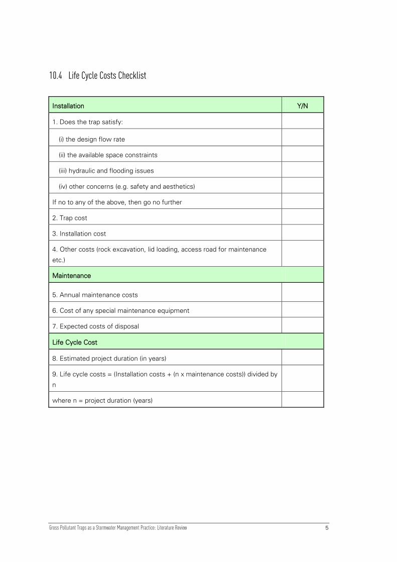
Gross Pollutant Traps as a Stormwater Management Practice: Literature Review 5
10.4 Life Cycle Costs Checklist
Installation Y/N
1. Does the trap satisfy:
(i) the design flow rate
(ii) the available space constraints
(iii) hydraulic and flooding issues
(iv) other concerns (e.g. safety and aesthetics)
If no to any of the above, then go no further
2. Trap cost
3. Installation cost
4. Other costs (rock excavation, lid loading, access road for maintenance
etc.)
Maintenance
5. Annual maintenance costs
6. Cost of any special maintenance equipment
7. Expected costs of disposal
Life Cycle Cost
8. Estimated project duration (in years)
9. Life cycle costs = (Installation costs + (n x maintenance costs)) divided by
n
where n = project duration (years)