Embed Size (px)
Citation preview
Migration of a Mobile Core Application to aSimplified Infrastructure
In-Service Performance Analysis
Priyanki Vashi
Master’s Thesis at School of Innovation Design and Technology
Mälardalen UniversityVästerås, Sweden
Migration of a Mobile Core Application to a Simplified Infrastructure, In-ServicePerformance AnalysisPRIYANKI VASHIMaster ThesisTechnical mentors at Ericsson: Leif Y. Johansson, Nikhil TikekarIndustrial mentors at Ericsson: Niklas Waldemar
Academic mentors at MDH: Thomas Nolte and Damir IsovicAcademic study advisor at MDH: Damir IsovicRegistration number:
©2012 PRIYANKI VASHIMaster’s Thesis at Ericsson (within Evolved Infrastructure PST group) in cooper-ation with the School of Innovation Design and TechnologyMälardalen UniversityBox 883, 721 23 Västerå[email protected], Sweden
i
Abstract
Ericsson has always strived for the technology leadership in its offeringby designing products based on the latest technology. Going ahead with asimilar thought it started exploring an idea of running a mobile core applicationusing a Simplified Infrastructure (SI) to eventually enable the Cloud basedsolutions. But in order to run these type of applications in the Cloud, thein-service performance provided by such a SI should be the same as the nativeinfrastructure in order to maintain the mobile core application’s QoS. "Highavailability" of the infrastructure is one of the measure of the ISP and from theISP point of view, such a migration would be considered feasible only if the SIis able to maintain the same level of availability as provided by the nativeinfrastructure solution without bringing in any major architecture changeswithin the SI. Hence this master thesis project investigates the feasibility ofachieving the same availability as before if the mobile core application is to bemigrated from the native infrastructure to the SI. Such a feasibility explorationwas the very first attempt with respect to the SI within Ericsson, which wasexecuted through this master thesis project. In order to achieve the goal ofthis thesis project a detailed system study was carried out, which focusedon the native infrastructure architecture, how it was maintaining the "highavailability" and how it differed from the SI.
In the end, it was possible to confirm that the level of availability ofinfrastructure services as provided through the SI will be higher than the nativeinfrastructure after the migration if the proposed suggestions of this masterthesis project are implemented successfully. These implementations also donot change the architecture of the SI in any major way. The end results of thisthesis project were also highly appreciated by Ericsson and are now part of thedevelopment plan for next mobile core infrastructure solution at Ericsson.
ii
Acknowledgements
The memories associated with this master thesis work will always havea special place in my heart and to have such an amazing feeling about myinvolvement in the work, I would like to start with thanking my Ericssonmentors and technical supervisors Leif Johansson, Nikhil Tikekar and NiklasWaldemar. Without their belief and trust in my capabilities it would not havebeen possible to reach an expected outcome. In addition, I would also liketo thank the designers, system managers and previous master thesis students(Isaac and Manuel) at Ericsson, who provided me a valuable information,which was not so evident in an available documentation in order to reachan expected outcome of this thesis project. Some of the learnings, which Ireally want to highlight here is, first why to bring a simplification and thensecondly how to bring the simplification in a more systematic way for a complexproducts such as the one studied as a part of this thesis project. Well inthis case, the simplification is mainly driven to enable the compatibility withthe latest technology involving the Multicores, Virtualization and hence CloudComputing and then leverage the benefits of the Cloud technology. Not onlytechnically it was rewarding for me to work in this area but also motivatingand an inspiring experience to interact with such a simple minded and humblebut yet very talented people of Ericsson.
I would also like to equally thank professor Thomas Nolte for all his supportand clear guidelines on my queries during this thesis work. I would honestlyadmit that I felt very happy and honoured when Thomas had agreed to be mythesis supervisor just based on an initial phone talk without even meeting me inperson. Interacting with him was a great experience. I am also very grateful toprofessor Damir Isovic for encouraging me throughout my master’s education asmy study advisor. Both of them have always answered my questions preciselyand provided me with a very valuable feedback and suggestions.
Last but not the least, I would also like to convey my deepest regards andsincere thanks to my family and more specifically to my mother, KantabenVashi and best friend, Ravikumar Darepalli, who is also my life partner. Theirwords were constant source of encouragement throughout my Life and sharingthe Master’s Education experience with them is none different than that !
Contents
Contents III
List of Figures V
List of Tables VI
List of Acronyms and Abbreviations VII
1 Introduction 11.1. Overview . . . . . . . . . . . . . . . . . . . . . . . . . . . . . . . . . 11.2. Related Work . . . . . . . . . . . . . . . . . . . . . . . . . . . . . . . 51.3. Problem Description . . . . . . . . . . . . . . . . . . . . . . . . . . . 91.4. Goals . . . . . . . . . . . . . . . . . . . . . . . . . . . . . . . . . . . 101.5. Methodology . . . . . . . . . . . . . . . . . . . . . . . . . . . . . . . 111.6. Scope . . . . . . . . . . . . . . . . . . . . . . . . . . . . . . . . . . . 141.7. Limitations . . . . . . . . . . . . . . . . . . . . . . . . . . . . . . . . 151.8. Target Audience . . . . . . . . . . . . . . . . . . . . . . . . . . . . . 151.9. Thesis Outline . . . . . . . . . . . . . . . . . . . . . . . . . . . . . . 16
2 General Background 172.1. Ericsson MSC Server Blade Cluster (MSC-S BC) . . . . . . . . . . . 17
2.1.1. Overview . . . . . . . . . . . . . . . . . . . . . . . . . . . . . 172.1.2. MSC-S BC Hardware Architecture . . . . . . . . . . . . . . . 192.1.3. MSC-S BC Software Architecture . . . . . . . . . . . . . . . . 222.1.4. MSC-S BC blade states for MSC-S BC . . . . . . . . . . . . . 252.1.5. MSC-S BC Hardware Management . . . . . . . . . . . . . . . 262.1.6. Link and Plane Handling for MSC-S BC . . . . . . . . . . . 282.1.7. MSC-S BC Functional View . . . . . . . . . . . . . . . . . . . 30
2.2. In-Service Performance (ISP) . . . . . . . . . . . . . . . . . . . . . . 322.2.1. ISP Overview . . . . . . . . . . . . . . . . . . . . . . . . . . . 322.2.2. Availability Measurements . . . . . . . . . . . . . . . . . . . . 33
2.3. SI Prototype Summary . . . . . . . . . . . . . . . . . . . . . . . . . . 342.3.1. Overview . . . . . . . . . . . . . . . . . . . . . . . . . . . . . 342.3.2. Verification Environment in Prototype . . . . . . . . . . . . . 37
iii
iv CONTENTS
3 Evaluation 413.1. Approach for Theoretical Study . . . . . . . . . . . . . . . . . . . . . 41
3.1.1. Analysis from ISP Perspective . . . . . . . . . . . . . . . . . 413.1.2. Current System Design Perspective . . . . . . . . . . . . . . . 43
3.2. Theoretical Study Findings . . . . . . . . . . . . . . . . . . . . . . . 453.2.1. Interfaces Identified . . . . . . . . . . . . . . . . . . . . . . . 463.2.2. List of Functions using NON-IP Interfaces . . . . . . . . . . . 46
3.3. Analysis of Unavailability of Identified Functions . . . . . . . . . . . 463.3.1. Function-1: Automatic Boot . . . . . . . . . . . . . . . . . . 463.3.2. Function-2: Supervision of Suspected Faulty Blade . . . . . . 483.3.3. Function-3: Link Fault Detection and Recovery . . . . . . . . 503.3.4. Function-4: Plane Fault Detection and Recovery . . . . . . . 513.3.5. Remaining functions: Function-5 to Function-10 . . . . . . . 533.3.6. Summary on Proposals for Different Functions . . . . . . . . 53
3.4. Verification of Proposals using Prototype . . . . . . . . . . . . . . . 543.4.1. Verification Strategy . . . . . . . . . . . . . . . . . . . . . . . 543.4.2. Test Case Description . . . . . . . . . . . . . . . . . . . . . . 553.4.3. Test Execution . . . . . . . . . . . . . . . . . . . . . . . . . . 56
4 Conclusions and Future Work 634.1. Conclusions . . . . . . . . . . . . . . . . . . . . . . . . . . . . . . . . 63
4.1.1. System Study . . . . . . . . . . . . . . . . . . . . . . . . . . . 634.1.2. Laboratory Tests . . . . . . . . . . . . . . . . . . . . . . . . . 64
4.2. Future Work . . . . . . . . . . . . . . . . . . . . . . . . . . . . . . . 64
Bibliography 67
A Mobile Network Architectures 71A.1. Mobile Network Architecture . . . . . . . . . . . . . . . . . . . . . . 71
A.1.1. Global System for Mobile Communication (GSM) . . . . . . 71A.1.2. Universal Mobile Telecommunications System (UMTS) . . . . 74
List of Figures
1.1. UMTS network topology. . . . . . . . . . . . . . . . . . . . . . . . . . . 21.2. Different phases of developement of Simplified Infrastructure idea. . . . 41.3. Ericsson MSC-S Blade Cluster view at blade level. . . . . . . . . . . . . 61.4. Ericsson MSC-S hybrid cluster topology (1st variant of SI prototype). . 71.5. Ericsson MSC-S external cluster topology (2nd variant of SI prototype). 81.6. Ericsson MSC-S split cluster topology (3rd variant of SI prototype). . . 91.7. Step-1 and Step-2 of used methodology. . . . . . . . . . . . . . . . . . . 131.8. Step 3,4 and 5 of used methodology. . . . . . . . . . . . . . . . . . . . . 14
2.1. MSC-S Blade Cluster rack view. . . . . . . . . . . . . . . . . . . . . . . 182.2. MSC-S Blade Cluster view at blade level. . . . . . . . . . . . . . . . . . 192.3. MSC-S Blade Cluster hardware architecture. . . . . . . . . . . . . . . . 202.4. MSC-S BC layered architecture. . . . . . . . . . . . . . . . . . . . . . . 232.5. BSOM signal flow diagram between MSC-S blades and SIS blade. . . . . 272.6. IS Links supervisions. . . . . . . . . . . . . . . . . . . . . . . . . . . . . 282.7. ISP Measurements. . . . . . . . . . . . . . . . . . . . . . . . . . . . . . . 332.8. Generic view of the Simplified Infrastructure (SI). . . . . . . . . . . . . 352.9. Ericsson MSC-S external cluster topology. . . . . . . . . . . . . . . . . . 362.10. The Stockholm Laboratory B network topology. . . . . . . . . . . . . . 39
3.1. BSOM signal flow diagram between MSC blades and a SIS blade. . . . . 443.2. Connectivity between CP Blades and Infrastructure Blades. . . . . . . . 453.3. Analysis of unavailability of automatic boot function. . . . . . . . . . . 473.4. Analysis of an unavailability of the MSC-S BC blade supervision function. 493.5. Analysis of an unavailability of link management function. . . . . . . . . 513.6. Analysis of unavailability of plane handling function. . . . . . . . . . . . 523.7. Analysis of unavailability for rest of the functions. . . . . . . . . . . . . 533.8. Summary of the proposed alternatives. . . . . . . . . . . . . . . . . . . . 54
A.1. GSM network topology. . . . . . . . . . . . . . . . . . . . . . . . . . . . 72A.2. UMTS network topology. . . . . . . . . . . . . . . . . . . . . . . . . . . 75
v
List of Tables
1.1. Global Mobile Data Traffic Growth . . . . . . . . . . . . . . . . . . . . . 3
2.1. Bridge machine’s features. . . . . . . . . . . . . . . . . . . . . . . . . . . 372.2. Cloud machine’s features. . . . . . . . . . . . . . . . . . . . . . . . . . . 382.3. Stockholm Laboratory B machines’ features. . . . . . . . . . . . . . . . 38
3.1. Compilation of tests results where one of the prototype MSC-S BC bladewas added to an existing MSC-S BC cluster. . . . . . . . . . . . . . . . 57
3.2. Compilation of tests results where one of the prototype MSC-S BC bladewas removed from an existing MSC-S BC cluster. . . . . . . . . . . . . . 58
vi

List of Acronyms and Abbreviations
3GPP Third Generation Partnership Project
API Application Programming Interface
APG Adjunct Processor Group
AUC Authentication Center
BSC Base Station Controller
BSS Base Station System
BTS Base Transceiver Station
BW Bandwidth
CAPEX Capital Expenditure
CPU Central Processing Unit
CS Circuit-Switched
CSCF Call Session Control Function
EIR Equipment Identity Register
eNB Evolved Node B
EPC Evolve Packet Core
ETSI European Telecommunications Standard Institute
GB Gigabyte
Gbps Gigabits per second
GHz Gigahertz
GPRS General Packet Radio Service
GSM Global System for Mobile communications
vii

viii LIST OF ACRONYMS AND ABBREVIATIONS
GUI Graphical User Interface
HLR Home Location Register
HSS Home Subscriber Server
IaaS Infrastructure as a Service
IEEE Institute of Electrical and Electronic Engineers
IMS IP Multimedia Subsystem
IMSI International Mobile Subscriber Identity
I/O Input/Output
IP Internet Protocol
ISO International Standard Organization
ISP In-service Performance
IT Information Technology
KVM Kernel-based Virtual Machine
LAN Local Area Network
LTE Long Term Evolution
MAC Media Access Control
MB Megabyte
Mbps Megabits per second
MGW Media Gateway
MIPS Million Instructions Per Second
ms milisecond
MSC Mobile services Switching Center
MSC-S Mobile Switching Center Server
MSC-S BC MSC-S Blade Cluster
MSISDN Mobile Station Integrated Services Digital Network
NGN Next Generation Network
NIST National Institute of Standards and Technology
ix
NMC Network Management Center
NMS Network Management Subsystem
NSS Network Switching Subsystem
OMC Operation and Maintenance Center
OPEX Operational Expenditure
OS Operating System
OSI Open Systems Interconnection
OSS Operation Support System
PaaS Platform as a Service
PC Personal Computer
PS Packet-Switched
PSTN Public Switched Telephone Network
QoE Quality of Experience
QoS Quality of Service
RAM Random Access Memory
RAN Radio Access Network
RNC Radio Network Controller
SI Simplified Infrastructure
SIM Subscriber Identity Module
SIS Site Infrastructure Support
SMS Short Message Service
SPX Signaling Proxy
SSH Secure Shell
UDP User Datagram Protocol
UPS Uninterruptible Power Supply
UMTS Universal Mobile Telecommunications System
UTRAN UMTS Radio Access Network

x LIST OF ACRONYMS AND ABBREVIATIONS
VLAN Virtual Local Area Network
VLR Visitor Location Register
VM Virtual Machine
VPN Virtual Private Network
Chapter 1
Introduction
The aim of this chapter is to introduce the wider group of readers with the workcarried out in this master thesis project. As a first step, an overview of the subjectand it’s related work is described so that the readers can connect and follow therest of the parts easily and logically. After that the problems, which had triggeredthis kind of work/study is described followed by a statement of the goals. Next, themethodology that is used to solve the identified problems is decsribed. Thereafterscope, limitations and the target audience of the project are clearly stated. Finally,an outline of the thesis is presented to highlight the structure of the thesis.
1.1. Overview
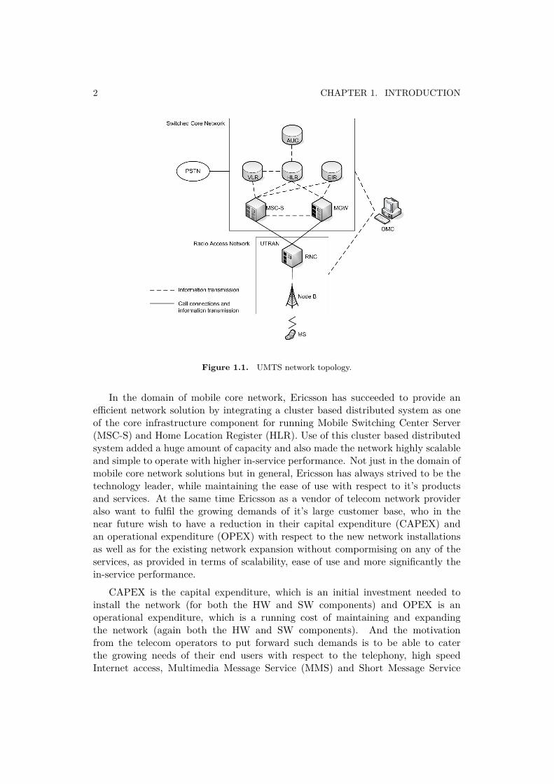
Today Global System for Mobile Communications (GSM) and Universal MobileTelecommunications System (UMTS)) are two of the most widely used mobile corenetwork architectures. GSM represents a second generation (2G) digital mobilenetwork architecture [1] and UMTS is a third generation (3G) mobile cellulartechnology standard [2]. On high level both the architecture topology is composedof three subsystems. The mobile core application (MSC-S application) and it’sinfrastructure (Ericsson MSC-S Blade Cluster), which is focus of this master thesisproject are part of one of the subsystem common to both the types of architectures.This subsystem is Network Switching Subsystem (NSS) and it is indicated asSwitched Core Network subsystem in UMTS network topology using Figure 1.1.
The NSS is composed of units like Mobile Switching Center Server (MSC-S),Home Location Register (HLR), Visitor Location Register (VLR) etc. so thatdifferent functions of this subsystem could be realized by different functional entitiesin the network [3]. Typically, a MSC-S node is responsible for the setup, supervision,and release of calls as well as for handling SMSs and managing terminals’ mobility.It also collects call billing data in order to send it to the Billing Gateway, whichprocesses this data to generate bills for the subscribers.
1
2 CHAPTER 1. INTRODUCTION
Figure 1.1. UMTS network topology.
In the domain of mobile core network, Ericsson has succeeded to provide anefficient network solution by integrating a cluster based distributed system as oneof the core infrastructure component for running Mobile Switching Center Server(MSC-S) and Home Location Register (HLR). Use of this cluster based distributedsystem added a huge amount of capacity and also made the network highly scalableand simple to operate with higher in-service performance. Not just in the domain ofmobile core network solutions but in general, Ericsson has always strived to be thetechnology leader, while maintaining the ease of use with respect to it’s productsand services. At the same time Ericsson as a vendor of telecom network provideralso want to fulfil the growing demands of it’s large customer base, who in thenear future wish to have a reduction in their capital expenditure (CAPEX) andan operational expenditure (OPEX) with respect to the new network installationsas well as for the existing network expansion without compormising on any of theservices, as provided in terms of scalability, ease of use and more significantly thein-service performance.
CAPEX is the capital expenditure, which is an initial investment needed toinstall the network (for both the HW and SW components) and OPEX is anoperational expenditure, which is a running cost of maintaining and expandingthe network (again both the HW and SW components). And the motivationfrom the telecom operators to put forward such demands is to be able to caterthe growing needs of their end users with respect to the telephony, high speedInternet access, Multimedia Message Service (MMS) and Short Message Service
1.1. OVERVIEW 3
(SMS) with as optimal cost as possible. Since the end users also expect thesame Quality of Experience (QoE) as they obtain while using wired devices [4] forsome of these services, this in turn puts high demand on the network performancewhile deliverying these services thorugh the mobile networks. Additionally in thegiven case expansion of the mobile network is directly proportional to the growingdemands of such services and it is very dynamic. Hence the CAPEX and the OPEXrequired to build and sustain such a deployment is becoming a major concern forthe telecom operators [5].
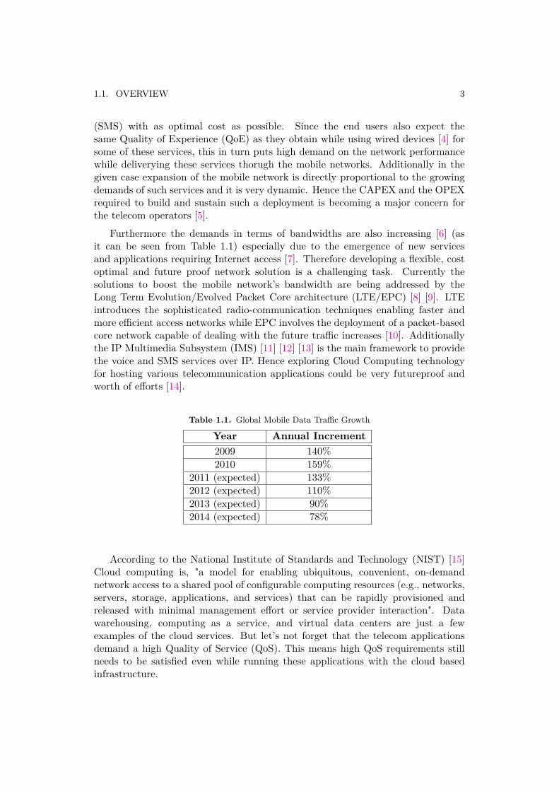
Furthermore the demands in terms of bandwidths are also increasing [6] (asit can be seen from Table 1.1) especially due to the emergence of new servicesand applications requiring Internet access [7]. Therefore developing a flexible, costoptimal and future proof network solution is a challenging task. Currently thesolutions to boost the mobile network’s bandwidth are being addressed by theLong Term Evolution/Evolved Packet Core architecture (LTE/EPC) [8] [9]. LTEintroduces the sophisticated radio-communication techniques enabling faster andmore efficient access networks while EPC involves the deployment of a packet-basedcore network capable of dealing with the future traffic increases [10]. Additionallythe IP Multimedia Subsystem (IMS) [11] [12] [13] is the main framework to providethe voice and SMS services over IP. Hence exploring Cloud Computing technologyfor hosting various telecommunication applications could be very futureproof andworth of efforts [14].
Table 1.1. Global Mobile Data Traffic Growth
Year Annual Increment2009 140%2010 159%
2011 (expected) 133%2012 (expected) 110%2013 (expected) 90%2014 (expected) 78%
According to the National Institute of Standards and Technology (NIST) [15]Cloud computing is, "a model for enabling ubiquitous, convenient, on-demandnetwork access to a shared pool of configurable computing resources (e.g., networks,servers, storage, applications, and services) that can be rapidly provisioned andreleased with minimal management effort or service provider interaction". Datawarehousing, computing as a service, and virtual data centers are just a fewexamples of the cloud services. But let’s not forget that the telecom applicationsdemand a high Quality of Service (QoS). This means high QoS requirements stillneeds to be satisfied even while running these applications with the cloud basedinfrastructure.
4 CHAPTER 1. INTRODUCTION
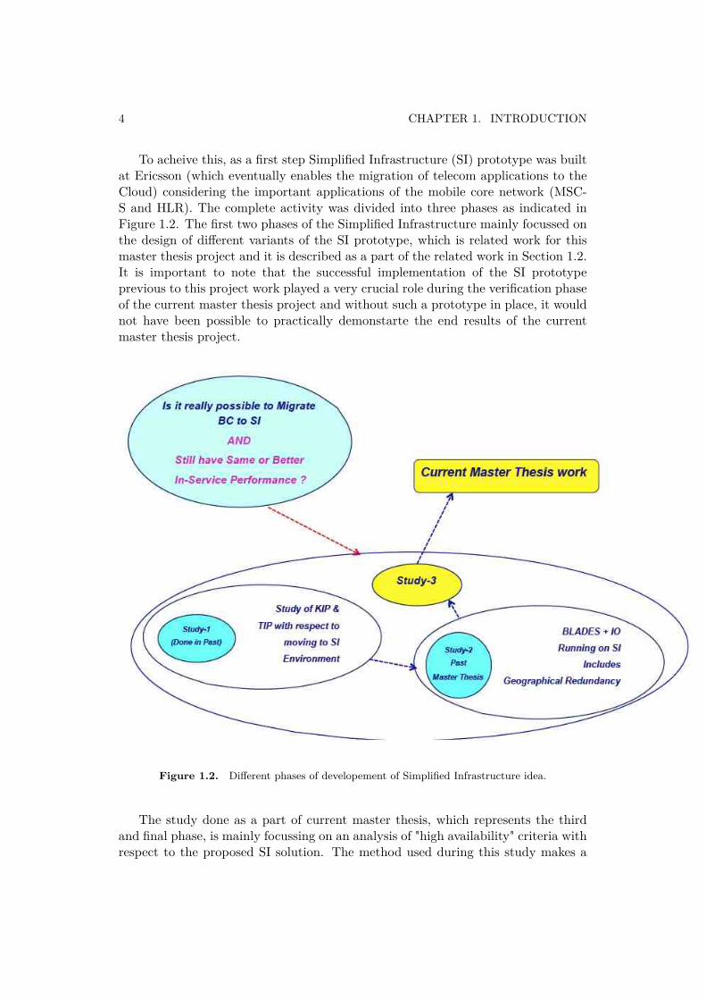
To acheive this, as a first step Simplified Infrastructure (SI) prototype was builtat Ericsson (which eventually enables the migration of telecom applications to theCloud) considering the important applications of the mobile core network (MSC-S and HLR). The complete activity was divided into three phases as indicated inFigure 1.2. The first two phases of the Simplified Infrastructure mainly focussed onthe design of different variants of the SI prototype, which is related work for thismaster thesis project and it is described as a part of the related work in Section 1.2.It is important to note that the successful implementation of the SI prototypeprevious to this project work played a very crucial role during the verification phaseof the current master thesis project and without such a prototype in place, it wouldnot have been possible to practically demonstarte the end results of the currentmaster thesis project.
Figure 1.2. Different phases of developement of Simplified Infrastructure idea.
The study done as a part of current master thesis, which represents the thirdand final phase, is mainly focussing on an analysis of "high availability" criteria withrespect to the proposed SI solution. The method used during this study makes a
1.2. RELATED WORK 5
very good logic and absolute clarity on what actions need to be taken in order toachieve the same or better level of availability if a mobile core application to bemigrated from an Ericsson native infrastructure (MSC-S BC) to SI, and eventuallyto the Cloud.
Using the end results obtained from the current master thesis project, it ispossible to say that there is a huge potential for hosting this type of mobile coreapplications using SI with the improved level of availability. This proof of conceptwould eventually help to secure the higher level of availability while migrating tothe Cloud as well. Of course, all the drawbacks that use of public Internet mayintroduce when providing these services must be kept in mind (Oredope and Liottaalso regarded this as an important concern in [16]).
1.2. Related Work
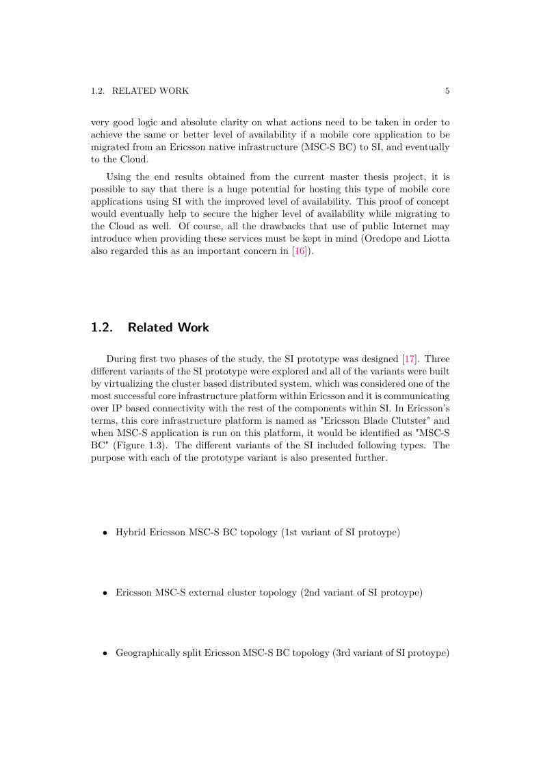
During first two phases of the study, the SI prototype was designed [17]. Threedifferent variants of the SI prototype were explored and all of the variants were builtby virtualizing the cluster based distributed system, which was considered one of themost successful core infrastructure platform within Ericsson and it is communicatingover IP based connectivity with the rest of the components within SI. In Ericsson’sterms, this core infrastructure platform is named as "Ericsson Blade Clutster" andwhen MSC-S application is run on this platform, it would be identified as "MSC-SBC" (Figure 1.3). The different variants of the SI included following types. Thepurpose with each of the prototype variant is also presented further.
• Hybrid Ericsson MSC-S BC topology (1st variant of SI protoype)
• Ericsson MSC-S external cluster topology (2nd variant of SI protoype)
• Geographically split Ericsson MSC-S BC topology (3rd variant of SI protoype)
6 CHAPTER 1. INTRODUCTION
Figure 1.3. Ericsson MSC-S Blade Cluster view at blade level.
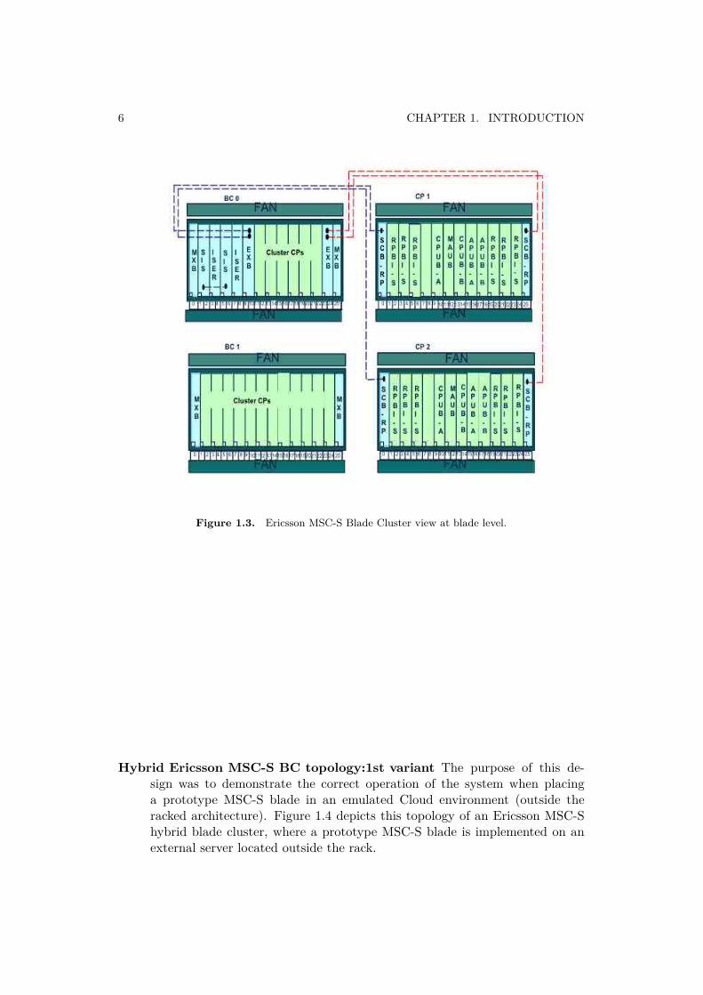
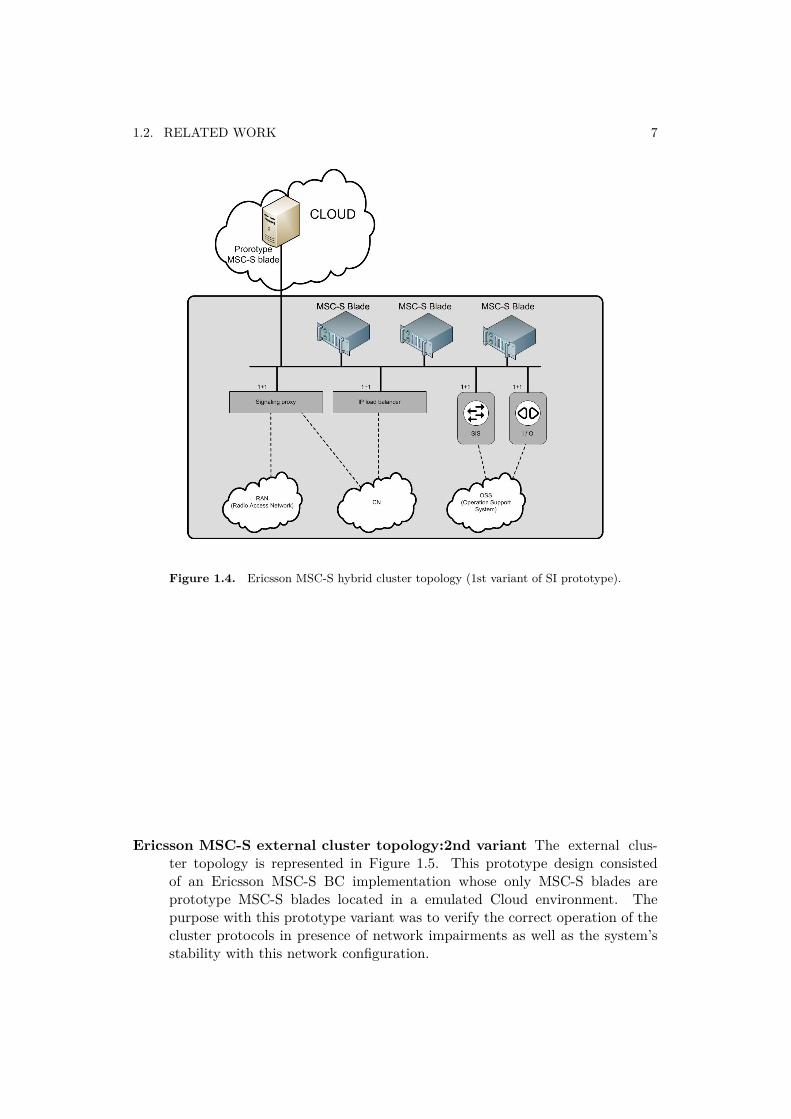
Hybrid Ericsson MSC-S BC topology:1st variant The purpose of this de-sign was to demonstrate the correct operation of the system when placinga prototype MSC-S blade in an emulated Cloud environment (outside theracked architecture). Figure 1.4 depicts this topology of an Ericsson MSC-Shybrid blade cluster, where a prototype MSC-S blade is implemented on anexternal server located outside the rack.
1.2. RELATED WORK 7
Figure 1.4. Ericsson MSC-S hybrid cluster topology (1st variant of SI prototype).
Ericsson MSC-S external cluster topology:2nd variant The external clus-ter topology is represented in Figure 1.5. This prototype design consistedof an Ericsson MSC-S BC implementation whose only MSC-S blades areprototype MSC-S blades located in a emulated Cloud environment. Thepurpose with this prototype variant was to verify the correct operation of thecluster protocols in presence of network impairments as well as the system’sstability with this network configuration.
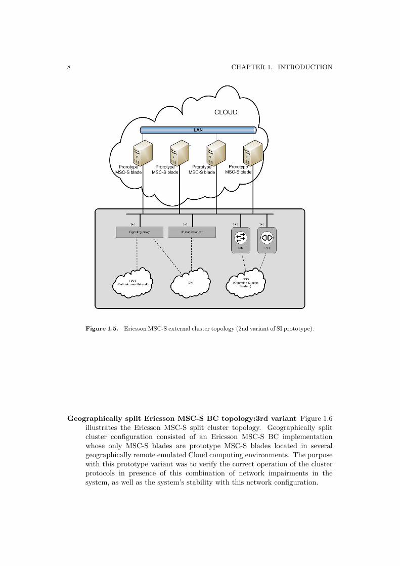
8 CHAPTER 1. INTRODUCTION
Figure 1.5. Ericsson MSC-S external cluster topology (2nd variant of SI prototype).
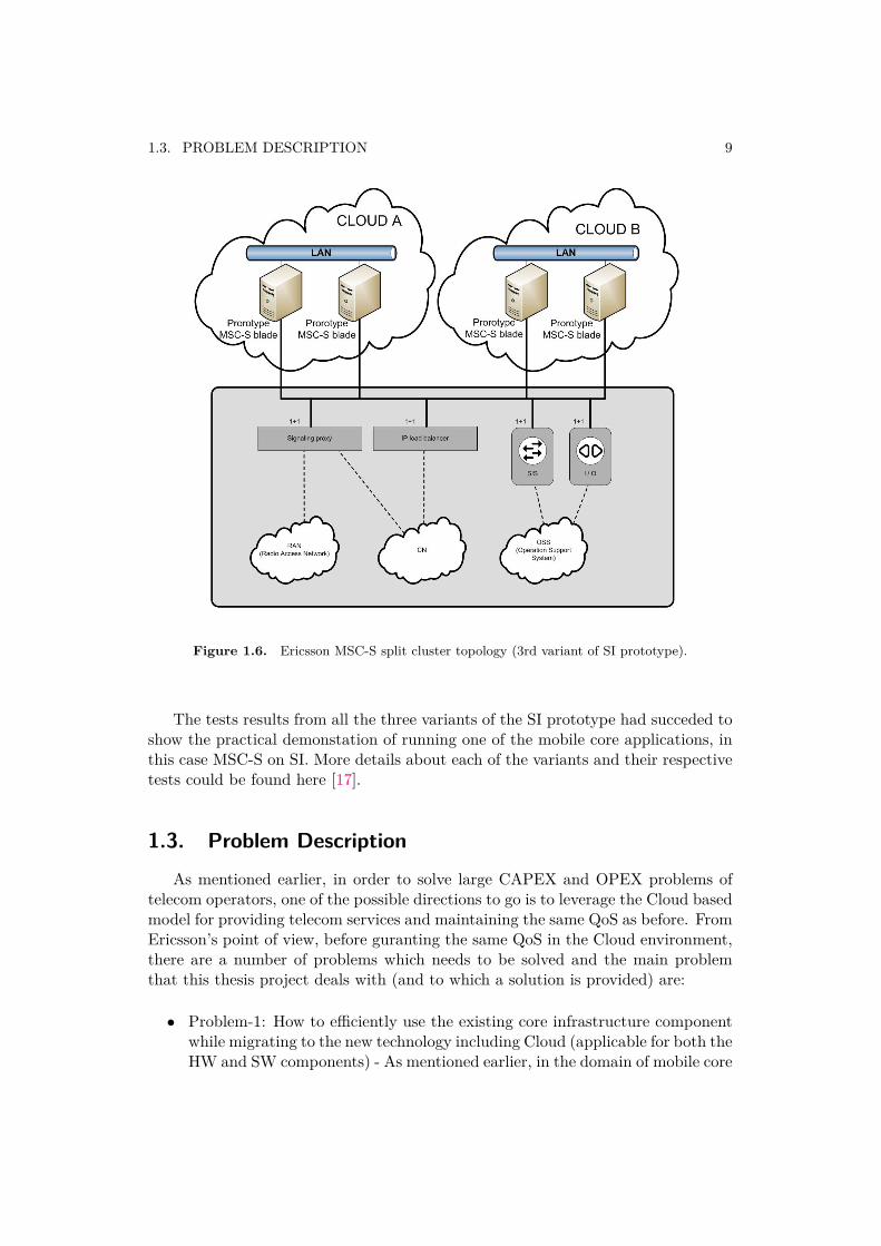
Geographically split Ericsson MSC-S BC topology:3rd variant Figure 1.6illustrates the Ericsson MSC-S split cluster topology. Geographically splitcluster configuration consisted of an Ericsson MSC-S BC implementationwhose only MSC-S blades are prototype MSC-S blades located in severalgeographically remote emulated Cloud computing environments. The purposewith this prototype variant was to verify the correct operation of the clusterprotocols in presence of this combination of network impairments in thesystem, as well as the system’s stability with this network configuration.
1.3. PROBLEM DESCRIPTION 9
Figure 1.6. Ericsson MSC-S split cluster topology (3rd variant of SI prototype).
The tests results from all the three variants of the SI prototype had succeded toshow the practical demonstation of running one of the mobile core applications, inthis case MSC-S on SI. More details about each of the variants and their respectivetests could be found here [17].
1.3. Problem DescriptionAs mentioned earlier, in order to solve large CAPEX and OPEX problems of
telecom operators, one of the possible directions to go is to leverage the Cloud basedmodel for providing telecom services and maintaining the same QoS as before. FromEricsson’s point of view, before guranting the same QoS in the Cloud environment,there are a number of problems which needs to be solved and the main problemthat this thesis project deals with (and to which a solution is provided) are:
• Problem-1: How to efficiently use the existing core infrastructure componentwhile migrating to the new technology including Cloud (applicable for both theHW and SW components) - As mentioned earlier, in the domain of mobile core
10 CHAPTER 1. INTRODUCTION
networks, Ericsson has succeeded to provide a scalable, easy to operate andhigher capacity network solution by introducing a cluster based distributedsystem, which forms one of the core infrastructure components in the corenetwork solution. This also means that over the period Ericsson had spenthuge amount of time and R&D efforts to develop such a solution and as a nextstep it is natural to explore an efficient use of this particular infrastructurecomponent, while migrating to the new technology like the Cloud. This willadd a value to the operational efficiency and hence reduce the time to market(TTM) while migrating to any new technology. If TTM is reduced then thiswould also mean better business efficiency.
• Problem-2: How to identify the limiting factors in the current cluster baseddistributed system, which might prevent it to migrate to SI while maintainingthe same level of availability before and after the migration - To make anefficient use of the cluster based distributed system, it was necessary tounderstand limitations, which might impact it’s availability after migrating toSI since in principle, SI would only support pure IP based connectivity. Henceinterfaces and functions using NON-IP interfaces (even though contributingto maintain the availability in the native solution) in the native infrastructureenvironment can not be supported. Also another such limitation to solvewas to decouple the HW and SW components as much as possible withoutbringing in major architectural changes. Next to solve was the ambiguity onthe usage of IP based and NON-IP based interfaces and associated functionsconnected to the in-service performance due to the lack of sufficient internalsystem documentation.
• Problem-3: How to gurantee the same level of availability (part of in-serviceperformance) while migrating the mobile core applications to the proposedSI from the native infrastructure - The solution of SI is proposed to addressthe problems stated above, however, when this project was proposed in April-2012, SI had not yet been analyzed and verified against the "high availability"criteria connected to its’ in-service performanance that these applicationsrequire in terms of QoS. Therefore a detailed study and thorough testingusing a prototype became mandatory to conclude the previously proposed SIsolution.
1.4. GoalsThe main goal of this master thesis project was to study the feasibility of
migration of one of the mobile core application from the native infrastructureto the Simplified Infrastructure to enable the Cloud based solutions. Such amigration would be considered feasible only if the Simplified Infrastructure is able tomaintain the same level of the availability as provided by the native infrastructure
1.5. METHODOLOGY 11
solution without bringining in any major architecture changes within the SimplifiedInfrastructure.
Before explaining detailed goals of this thesis project, it is necessary to elaborateon the meaning of important terms. In the given context,
• In-service performance defines the measure of availability, which is measuredusing the in-service performance statistics collected internally within Ericsson.
• Cloud based solutions here represents geographically separated resources -In the current project it represents a group of virtual blades running as adistributed cluster with only IP based connectivity. This configuration isequivalent to a distributed cluster formed by physical blades running withinthe native infrastructure. In this case there exist two variants, one is calledIntegrated Site (IS) and the other is Ericsson Blade System (EBS).
The main goal is divided into three subgoals as presented below.
Goal-1: Study the architecture of the native infrastructure, understand how it wasmaintaining the high availability and how it differs in maintaining the highavailability compare to the Simplified Infrastructure.
Goal-2: Based on the identified differences between two infrastructure solutionsanalyze if there is a way to propose a solution so that the same level ofavailability can be achieved before and after the migration without bringingin major architecture changes within the Simplified Infrastructure.
Goal-3: If there is a suitable solution, conduct various tests using the existingSimplified Infrastructure prototype to practically demonstarte the proposedsolution works as expected and hence help to provide a concrete conclusionon the feasibility of this migration.
1.5. MethodologyIn order to fulfill the goals of this thesis project, a qualitative approach was
utilized. Secondary research was used as a qualitative method, which also includesunderstanding of the work done as a part of the previous studies. Moreover, thisresearch provided material for the background chapter and allowed to obtain a fullstate-of-the-art overview of the subject. This literature review also provided a solidfoundation upon which various ideas for different proposals are built.
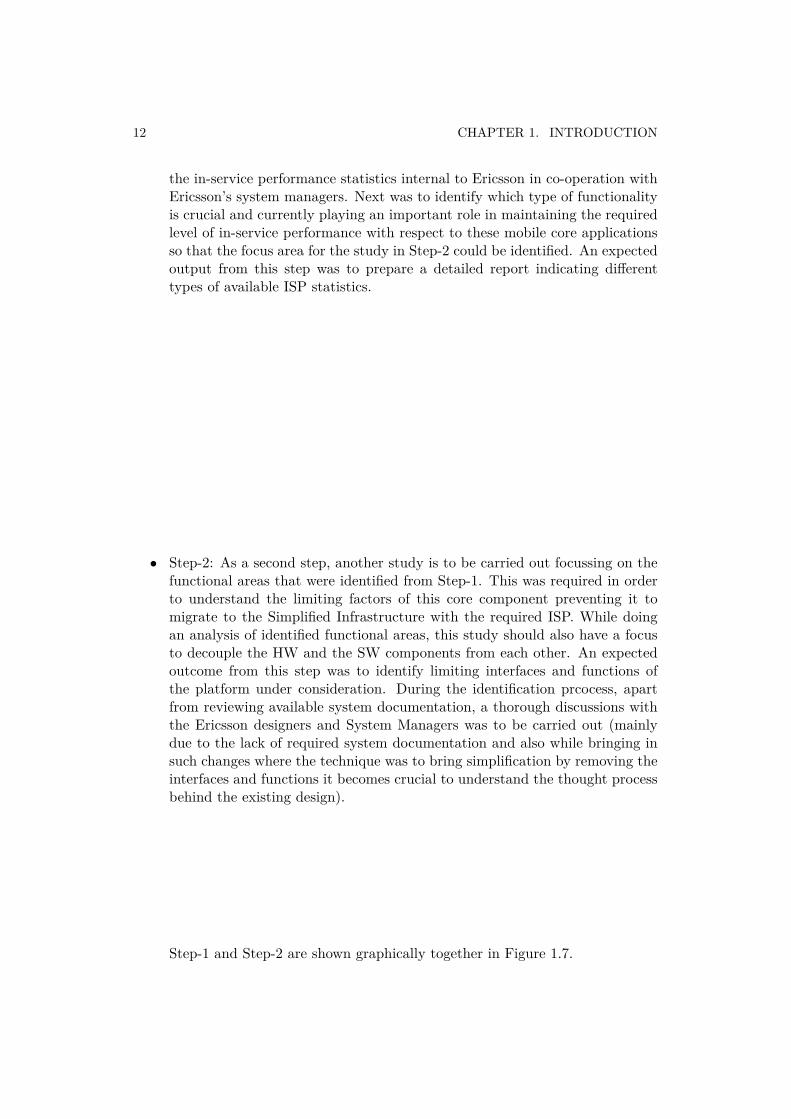
• Step-1: As a first step, a study to be done in order to understand what definesthe in-service performance and what kind of data is available as a part of
12 CHAPTER 1. INTRODUCTION
the in-service performance statistics internal to Ericsson in co-operation withEricsson’s system managers. Next was to identify which type of functionalityis crucial and currently playing an important role in maintaining the requiredlevel of in-service performance with respect to these mobile core applicationsso that the focus area for the study in Step-2 could be identified. An expectedoutput from this step was to prepare a detailed report indicating differenttypes of available ISP statistics.
• Step-2: As a second step, another study is to be carried out focussing on thefunctional areas that were identified from Step-1. This was required in orderto understand the limiting factors of this core component preventing it tomigrate to the Simplified Infrastructure with the required ISP. While doingan analysis of identified functional areas, this study should also have a focusto decouple the HW and the SW components from each other. An expectedoutcome from this step was to identify limiting interfaces and functions ofthe platform under consideration. During the identification prcocess, apartfrom reviewing available system documentation, a thorough discussions withthe Ericsson designers and System Managers was to be carried out (mainlydue to the lack of required system documentation and also while bringing insuch changes where the technique was to bring simplification by removing theinterfaces and functions it becomes crucial to understand the thought processbehind the existing design).
Step-1 and Step-2 are shown graphically together in Figure 1.7.
1.5. METHODOLOGY 13
Figure 1.7. Step-1 and Step-2 of used methodology.
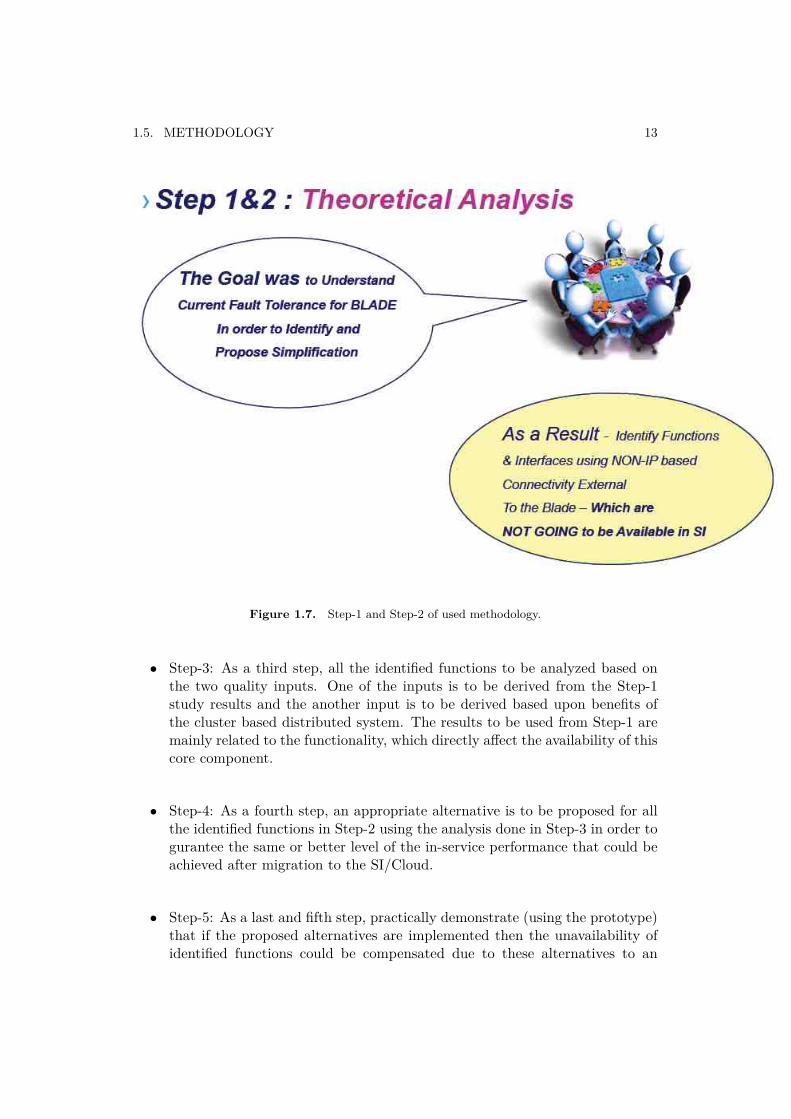
• Step-3: As a third step, all the identified functions to be analyzed based onthe two quality inputs. One of the inputs is to be derived from the Step-1study results and the another input is to be derived based upon benefits ofthe cluster based distributed system. The results to be used from Step-1 aremainly related to the functionality, which directly affect the availability of thiscore component.
• Step-4: As a fourth step, an appropriate alternative is to be proposed for allthe identified functions in Step-2 using the analysis done in Step-3 in order togurantee the same or better level of the in-service performance that could beachieved after migration to the SI/Cloud.
• Step-5: As a last and fifth step, practically demonstrate (using the prototype)that if the proposed alternatives are implemented then the unavailability ofidentified functions could be compensated due to these alternatives to an
14 CHAPTER 1. INTRODUCTION
extent, which is acceptable to conclude that the platform under considerationwill have the same level of in-service performance with this proposed SimplifiedInfrastructure.
Steps 3,4 and 5 are shown graphically in Figure 1.8.
Figure 1.8. Step 3,4 and 5 of used methodology.
1.6. Scope
• Within Ericsson, there exist different variants of the processor and infrastruc-ture blades. A certain combination of the processor and the infrastructureblades together form one of the core infrastructure components within a corenetwork solution. As part of this thesis project, one such variant (IS basedBlade Cluster) was studied, and the mobile core application considered wasMSC-S.
1.7. LIMITATIONS 15
• A similar study would be required to carry out for the other variants ofprocessor and infrastructure blades such as EBS (Ericsson Blade System),but the method used in this master’s thesis could be equally efficient for thatas well.
• The practical experiment was carried out using a Ericsson proprietary MSCapplication prototype with limited functionality. In the future further studiesshould be conducted to verify the correct behaviour of a completely functionalEricsson MSC-S BC application as well as the other (related) applicationsto see if the results of this study can be generalized to the other (similar)applications.
• Study of certain software component, (even though they are part of the chosenvariant) was out of the scope of this master’s thesis. One such softwarecomponent is the IP Stack designed by Telebit (TIP stack).
• Troubleshooting of the prototyping problems was also decided to be keptoutside the scope of this thesis work.
1.7. LimitationsOne of the main limitation in this thesis work was the use of a simulated
environment during the verification phase.
During the last step, which was focusing on verification of the proposedalternatives, the GSM and UMTS type of mobile calls were generated usinga simulated environment. However, since the main goal of this thesis was todemonstrate that the proposed idea works (as a proof of concept), a simulatedenvironment was enough to carry out this initial verification.
1.8. Target AudienceThe primary audience of this work is the Ericsson’s internal design and systems
group within Evolved infrastructure. The idea here was to show that the proposedmethodology and derived results as one approach in order to simplify such a complexplatform without impacting it’s in-service performance. Through such an approachit would be possible to have an open discussion on the proposed alternatives.
Another important target audience is Ericsson’s customers, who wish to leveragethe benefits of the cloud technology with respect to their current mobile core networksolution.
In addition to these readers, a specific group of researchers is interested inacquiring the knowledge with respect to a telecom network performance in the
16 CHAPTER 1. INTRODUCTION
Cloud, such as the one studied in this thesis project can also take the advantage ofthe described metodology.
1.9. Thesis OutlineThe thesis is structured in a linear manner, where the earlier chapters provide
a general overview of the subjects necessary to understand the remaining chaptersof the thesis. It is strongly recommended that the reader should thoroughly studythe introdcution and the background chapters in order to provide an appropiatecontext for the subsequent experimental work.
Chapter 1 provides an introduction to the thesis. Chapter 2 provides relatedbackground information. Chapter 3 describes an evaluation part of this thesis work,which talks about the theoretical study findings and various conclusions of thefindings. It also discusses details about the prototype, the verification strategy andthe test cases used for verifying the findings of this theoretical study. Chapter4 presents final conclusions and suggested future work. Appendix A explains abrief architecture of different types of mobile core networks (GSM and UMTSintroduction). Appendix B (confidential) is a manual to configure a prototypetesting environment used during this thesis work.
Chapter 2
General Background
The purpose of this chapter is to give a brief overview of the technologiesand concepts involved in this thesis project so that the readers can easilyunderstand/visualize how the work has been carried out. In addition theinformation provided here focuses only on the important areas of the subject, whichare directly related to this project without going into unnecessary details.
Since the purpose of this thesis project was to analyze whether one of thecrucial infrastructure components of a mobile core network could be migratedto a Simplified Infrastructure without any impact on it’s in-service performance,therefore at the begining of the chapter important concepts of the MSC-S BCarchitecture are described. The architecture includes both the HW and SWcomponents description (Section 2.1). Next the important concepts, definitionsand terminologies with respect to the in-service performance of the platform(Section 2.2) are described. In the end a theoretical description of the Ericsson’sMSC-S BC prototype and test environment (Section 2.3) is presented.
2.1. Ericsson MSC Server Blade Cluster (MSC-S BC)
2.1.1. Overview
The Ericsson Mobile Switching Center Server (MSC-S) [18] forms one ofthe important components within the Ericsson’s Mobile Softswitch solution [19].Important functions of this server includes, set up and releases of end-to-end calls,handling mobility and hand-over of the calls between dfferent mobiles, the callcharging etc. However recently it has been replaced by a more sophistacated state-of-the-art solution, called the MSC-S Blade Cluster (MSC-S BC). MSC-S BC isdesigned on the principle of a cluster based distributed system.
All the components of the Ericsson MSC-S BC are implemented as a rackedarchitecture. As a part of this racked type of architecture, MSC-S BC can have
17
18 CHAPTER 2. GENERAL BACKGROUND
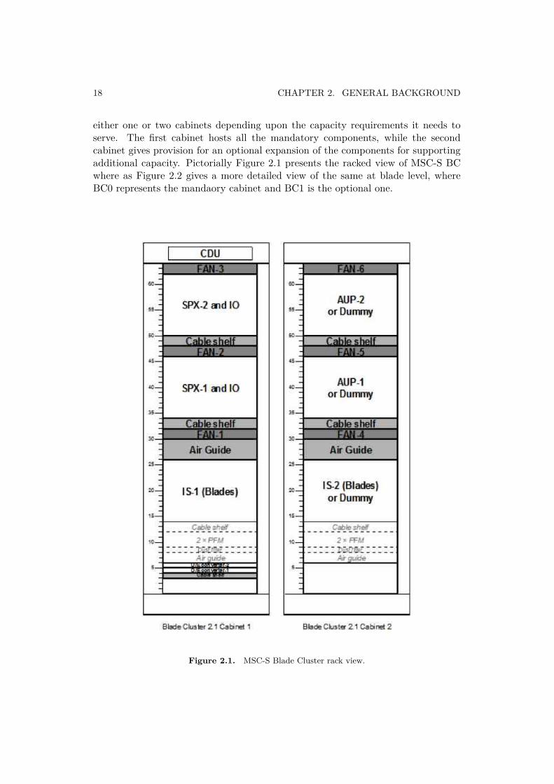
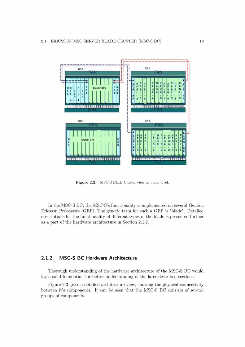
either one or two cabinets depending upon the capacity requirements it needs toserve. The first cabinet hosts all the mandatory components, while the secondcabinet gives provision for an optional expansion of the components for supportingadditional capacity. Pictorially Figure 2.1 presents the racked view of MSC-S BCwhere as Figure 2.2 gives a more detailed view of the same at blade level, whereBC0 represents the mandaory cabinet and BC1 is the optional one.
Figure 2.1. MSC-S Blade Cluster rack view.
2.1. ERICSSON MSC SERVER BLADE CLUSTER (MSC-S BC) 19
Figure 2.2. MSC-S Blade Cluster view at blade level.
In the MSC-S BC, the MSC-S’s functionality is implemented on several GenericEricsson Processors (GEP). The generic term for such a GEP is "blade". Detaileddescriptions for the functionality of different types of the blade is presented furtheras a part of the hardware architecture in Section 2.1.2.
2.1.2. MSC-S BC Hardware Architecture
Thorough understanding of the hardware architecture of the MSC-S BC wouldlay a solid foundation for better understanding of the later described sections.
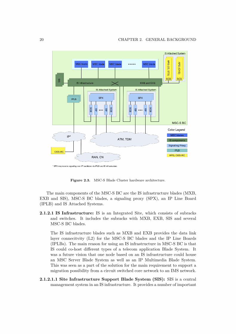
Figure 2.3 gives a detailed architecture view, showing the physical connectivitybetween it’s components. It can be seen that the MSC-S BC consists of severalgroups of components.
20 CHAPTER 2. GENERAL BACKGROUND
Figure 2.3. MSC-S Blade Cluster hardware architecture.
The main components of the MSC-S BC are the IS infrastructure blades (MXB,EXB and SIS), MSC-S BC blades, a signaling proxy (SPX), an IP Line Board(IPLB) and IS Attached Systems.
2.1.2.1 IS Infrastructure: IS is an Integrated Site, which consists of subracksand switches. It includes the subracks with MXB, EXB, SIS and severalMSC-S BC blades.
The IS infrastructure blades such as MXB and EXB provides the data linklayer connecitvity (L2) for the MSC-S BC blades and the IP Line Boards(IPLBs). The main reason for using an IS infrastructure in MSC-S BC is thatIS could co-host different types of a telecom application Blade System. Itwas a future vision that one node based on an IS infrastructure could housean MSC Server Blade System as well as an IP Multimedia Blade System.This was seen as a part of the solution for the main requirement to support amigration possibility from a circuit switched core network to an IMS network.
2.1.2.1.1 Site Infrastructure Support Blade System (SIS): SIS is a centralmanagement system in an IS infrastructure. It provides a number of important
2.1. ERICSSON MSC SERVER BLADE CLUSTER (MSC-S BC) 21
functions such as Integrated Site Management (ISM), fault management,software management and hardware management for all the componentsresiding within an IS subrack. Two SIS blades are present to provide 1+1redundancy.
2.1.2.1.2 Main Switch Blade System (MXB): As mentioned earlier, MXB isa L2 switch, for providing the switching function inside a subrack, for exampleinternal connectivity between all the MSC-S BC blades.
2.1.2.1.3 External LAN Attachment Blade System (EXB): The EXB is alsothe L2 switch within the IS subrack to provide connectivity with thecomponents residing outside the IS subrack. These components are togetherknown as the IS Attached System (explained further).
2.1.2.1.4 MSC-S BC blades: The MSC blades reside within the IS L2 infras-tructure. This element forms a cluster, which is a group of central processors(CPs) located in an IS subrack. This means that the cluster system is not aself contained system but part of a networked solution and can be seen as acluster of independent multicore processors working together.
MSC-S BC blades host the MSC server application. Since multiple MSC-S BCblades exist, the load is distributed over all the available blades. As mentionedearlier, they are based on a single sided multicore processor architecture,which in turn uses the Generic Ericsson Processor Board (GEP) as a hardwareplatform. As the blades are single sided it relies on a logical M+N redundencyprinciple to handle the fault situation during live traffic as well as for certainmaintenance activities. In M+N redundency, M represnts the actual numberof blades required to handle the total traffic and N represents the additionalnumber of blades provisioned to enable redundancy in case of one or moreblade faults/failures occur. The most usual case is to have M+1 numberof blades (with N=1), which are configured for handling the total trafficrequirements.
From a functional point of view, all MSC-S BC blades are equal. It meansthat they run the same MSC application software, but for certain functionMSC-S BC blades can get certain logical roles. These roles are automaticallyassigned in a dynamic way and all the MSC-S BC blades can take such alogical role. In the given context, dynamic means that if a blade that has acertain logical role becomes unavailable (e.g. due to the HW or SW fault)or if this certain logical role has to be moved to another blade due to loadrebalancing, the logical role is automatically assigned to another MSC-S BCblade.
2.1.2.1.5 IP Line board (IPLB): The IPLBs distribute all the IP packets to theMSC-S BC components. In standard configuration the MSC-S BC consists oftwo IPLBs for redundancy. Optionally the MSC-S BC can have an additional
22 CHAPTER 2. GENERAL BACKGROUND
IPLB pair for operation and maintenance. The IPLBs reside within the IS L2infrastructure.
2.1.2.2 IS Attached System: Not all the components in the MSC-S BC fulfill therequirements to reside in the L2 infrastructure provided by an IS framework.These requirements are that certain L2 connectivity facilities, like the LinkLayer Aggregation with Ericsson proprietary extension must be supported.Components in the MSC-S BC which do not support these requirements arethe SPXs and the I/O system. They are connected to the IS infrastructure asan IS Attached System.
L2 connectivity of the components in an IS Attached System is providedby the Switch Core Board (SCB) as shown in Figure 2.2. For redundancypurposes two SCBs are present per subrack. To achieve connectivity betweenthe components of an IS infrastructure and an IS Attached System, the EXBsin the IS infrastructure are connected with the SCBs of an IS Attached System.
2.1.2.2.1 Signalling Proxy (SPX): SPX is the part of an IS Attached Systemand this element is responsible for distributing external SS7 signaling trafficover the MSC-S BC so that it can be processed. The traffic distribution tothe MSC-S BC blades is done on an algorithmic basis (e.g. using a RoundRobin scheduling algorithm).
The SPX is based on a double sided processor, which in turn uses twoGEP boards as a hardware platform. The double sided processor offers 1+1redundancy. The MSC-S BC consists of two SPXs, which can be used eitherin a load-sharing manner or in a redundant manner. How the SPXs are useddepends on the network configuration.
2.1.2.2.2 I/O system: As the name suggests, the I/O system provides theinput/output functionality for the MSC-S BC blades and the SPXs. TheMSC-S BC contains two I/O systems. One is meant for basic input/outputand performance management while the second is used for charging andaccounting data collection from all the MSC-S BC blades and SPXs. EachI/O is also based on a GEP hardware, running a Microsoft Windows ClusterServer as an operating system. This provides a 1+1 redundancy for eachI/O device. The I/O system also communicates with the Operation SupportSystem (OSS) of a network.
2.1.3. MSC-S BC Software Architecture
The software structure of the MSC-S BC system is designed with the aim ofupholding the functional modularity in order to simplify the installation, operationand maintenance of the system apart from achieving the required functionalrequirements.
2.1. ERICSSON MSC SERVER BLADE CLUSTER (MSC-S BC) 23
Figure 2.4. MSC-S BC layered architecture.
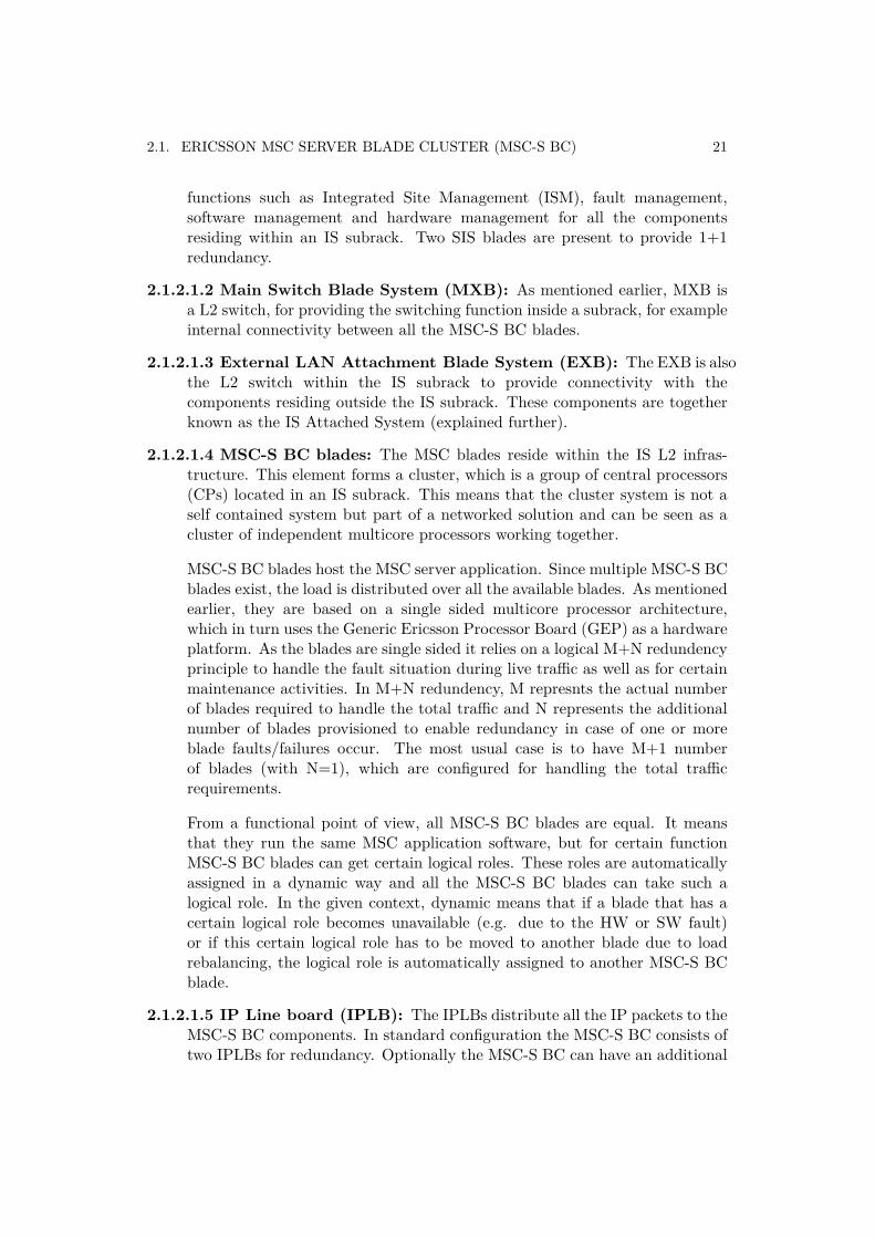
In every MSC-S BC blade the following software layers exists.
1 An operating system, Ericsson Linux (ENUX), based on LINUX.
2 The Hardware Adaptation Layer (HAL) and the Operating System Interface(OSI) layers to offer a generic interface to the commercial hardware and theoperating system. The HAL forms a set of drivers while the OSI providesaccess to the functions that the operating system offers.
3 An APZ Virtual Machine (APZ-VM) that handles the traffic, which is IP-based(over UDP, TCP or SCTP) from the SPX, IO and MSC-S BC blades.
24 CHAPTER 2. GENERAL BACKGROUND
4 An online ASA compiler (ASAC) that operates in two compilation modes, basicand optimized. The compiler that compiles the code is called a JIT compiler(Just In time). The compilation mode is selected on block level. Basic modeis used for most blocks and it provides additional information for fault finding.
5 The APZ OS (central processor operating system) provides the service functionsfor an application software and the functions for administration, operationand maintenance of the software and hardware.
6 Applications SW layer.
7-10 I/O system Software layers.
By combining the above described software layers different subsystems areformed. The important ones with respect to this thesis are:
CP Hardware Subsystem (CPHW) This subsystem contains the CP hardwareplatform. Software layer 1 and 2 in Figure 2.4 together form the CentralProcessor Hardware Subsystem. The main responsibility of the CPHWsubsystem is,
• To provide the central processor board (CPUB), with the ENUX OS• To provide an execution platform for the PLEX Engine subsystem (PEs)
services such as ASAC and APZ-VM• To provide the support functions for other subsystems such as the PLEX
Engine subsystem (PEs) and the Maintenance subsystem (MAS) tocreate a central processor that fulfills the telecom domain requirements
• To provide the physical interfaces (NIC) towards the other MSC-S BCcluster blades, SPX or IS components via the IS infrastructure
• To provide different protocol stacks (like the Telebit IP stack (TIP) andthe OS Kernel IP stack (KIP))
• To provide an execution platform for the Extra Processing Units (XPU)applications
Maintenance Subsystem (MAS) This subsystem has a responsibility to pro-vide the functions for an automatic HW and SW fault handling for individualMSC-S BC blades during live traffic as well as for the important maintenancefunctions through a manual intervation by an exchange technician. Faultmanagement is provided through a Blade Fault Tolerance architecture (BFT).More details on the types of blade level fault tolerance are covered as a partof Chapter 3 (Evaluation).
Cluster Quorum Subsystem (CQS) This subsystem has the responsibility formaking a group of individual MSC-S BC blades to operate as a cluster.
2.1. ERICSSON MSC SERVER BLADE CLUSTER (MSC-S BC) 25
It also provides cluster level HW and SW fault management functions.Fault management is provided through a Cluster Fault Tolerant architecture(CFT). The various functions provided through the Cluster Fault Tolerantarchitecture includes, multiple blade and link fault management, AutomaticQuorum Recovery (AQR) and partition handling.
2.1.4. MSC-S BC blade states for MSC-S BCEach MSC-S BC blade has a certain status within the MSC-S BC. The status of
a MSC-S BC blade is described by a Cluster Central Processor State (mostly justcalled CP state or state). In addition to the CP state, an optional CP state and anapplication substates also exist. These optional states describe the current situationof a blade in more detail than the CP state does. As a part of this section only CPstates are discussed since it is believed that it would be sufficent with respect to thescope of this thesis work.
The possible CP states are:
ACTIVE: The blade is part of the quorum and is used for normal traffic execution.Blades in state ACTIVE are part of the Operative Group (OG) and are keptconsistent from the configuration point of view.
PASSIVE: The blade is a part of a quorum but it is not used for the trafficexecution. The blade is either not activated yet or has been put to PASSIVEdue to inconsistency reasons.
INTERMEDIATE: A previously ACTIVE blade that is temporarily out of thequorum either due to the blade recovery or because this was ordered bya command. The blade is expected to return to an ACTIVE state eitherautomatically or by a command, respectively.
RECOVERY: A previously ACTIVE blade that is temporarily out of the quorumdue to an extended recovery activities, or a previously PASSIVE blade that istemporarily out of the quorum due to the blade recovery activities, or a bladethat has missed to rejoin the quorum during an Automatic Quorum Recovery(AQR), is in the state RECOVERY. Typically, the RECOVERY state is atransient state and it is expected that the blade will automatically return toits previous state without manual intervention.
NON-OP: The blade is non-operational either due to the permanent failure orbecause this was ordered by a command.
UNDEFINED: This is not a real state. The blade is not a member of the clusterand it is unknown to the other blades.
26 CHAPTER 2. GENERAL BACKGROUND
2.1.5. MSC-S BC Hardware Management
As mentioned above, the IS infrastructure offers certain HW managementfunctions to the MSC-S BC blades through a SIS blade. The MSC Blade System(MSC-BS) uses the private hardware management. It means that an IS will notissue a MSC-BS specific alarms, and not power off or reset the MSC blades in faultsituations. This is up to the MSC blades and is handled by various functions withinthe fault management functionality of the blades as a part of the BFT and CFTarchitecture (i.e. MSC-S BC blades are able to power on and off other MSC-S BCblades).
An automatic fault management and the manual fault management includingcertain maintenance functions on the MSC-S BC blades require communicationwith IS HW management functions located on the SIS. The function of a MSC-S BC blade, which takes care of this, is called as the Blade System Operationand Maintenance Master (BSOM). Each MSC-S BC blade has a local BSOM. TheBSOM is implemeted as a software component within PEs and it communicateswith both the CPHW and MAS as a part of fault handling (both automatic andmanual types of fault handling).
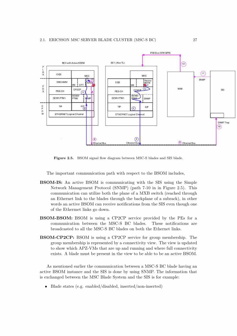
Only one MSC-S BC blade in the MSC Blade System can actually communicatewith the SIS. The MSC-S BC blade, which can communicate with the SIS isidentified as an active BSOM. The role of an active BSOM can be taken by anyMSC-S BC blade and is assigned dynamically by the Cluster Handler (CH) function.Messages sent from a MSC-S BC blade to the SIS are first sent from the local BSOMto an active BSOM as indicated by the path going through the points 1-2-3-4-5-6in Figure 2.5 and then forwarded to the SIS through the path going through thepoints 7-8-9-10. Similarly messages sent from the SIS to a particular MSC-S BCblade are first sent to an active BSOM and then forwarded to the local BSOM onthe concerned MSC-S BC blade(s).
2.1. ERICSSON MSC SERVER BLADE CLUSTER (MSC-S BC) 27
Figure 2.5. BSOM signal flow diagram between MSC-S blades and SIS blade.
The important communication path with respect to the BSOM includes,
BSOM-IS: An active BSOM is communicating with the SIS using the SimpleNetwork Management Protocol (SNMP) (path 7-10 in in Figure 2.5). Thiscommunication can utilize both the plane of a MXB switch (reached throughan Ethernet link to the blades through the backplane of a subrack), in otherwords an active BSOM can receive notifications from the SIS even though oneof the Ethermet links go down.
BSOM-BSOM: BSOM is using a CP2CP service provided by the PEs for acommunication between the MSC-S BC blades. These notifications arebroadcasted to all the MSC-S BC blades on both the Ethernet links.
BSOM-CP2CP: BSOM is using a CP2CP service for group membership. Thegroup membership is represented by a connectivity view. The view is updatedto show which APZ-VMs that are up and running and where full connectivityexists. A blade must be present in the view to be able to be an active BSOM.
As mentioned earlier the communication between a MSC-S BC blade having anactive BSOM instance and the SIS is done by using SNMP. The information thatis exchanged between the MSC Blade System and the SIS is for example:
• Blade states (e.g. enabled/disabled, inserted/non-inserted)
28 CHAPTER 2. GENERAL BACKGROUND
• Sensor information (e.g. temperature)
• Lock/unlock request
• Link failure
• LED status
2.1.6. Link and Plane Handling for MSC-S BC2.1.6.1 Introduction
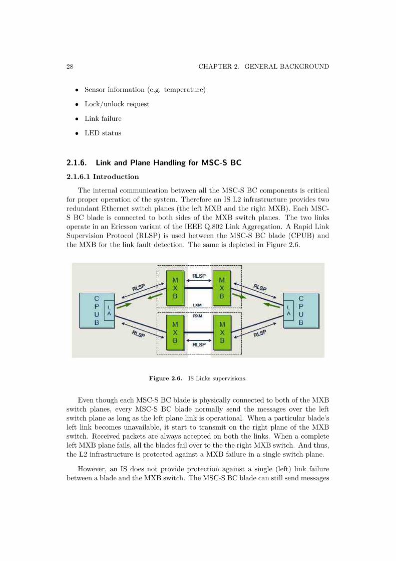
The internal communication between all the MSC-S BC components is criticalfor proper operation of the system. Therefore an IS L2 infrastructure provides tworedundant Ethernet switch planes (the left MXB and the right MXB). Each MSC-S BC blade is connected to both sides of the MXB switch planes. The two linksoperate in an Ericsson variant of the IEEE Q.802 Link Aggregation. A Rapid LinkSupervision Protocol (RLSP) is used between the MSC-S BC blade (CPUB) andthe MXB for the link fault detection. The same is depicted in Figure 2.6.
Figure 2.6. IS Links supervisions.
Even though each MSC-S BC blade is physically connected to both of the MXBswitch planes, every MSC-S BC blade normally send the messages over the leftswitch plane as long as the left plane link is operational. When a particular blade’sleft link becomes unavailable, it start to transmit on the right plane of the MXBswitch. Received packets are always accepted on both the links. When a completeleft MXB plane fails, all the blades fail over to the the right MXB switch. And thus,the L2 infrastructure is protected against a MXB failure in a single switch plane.
However, an IS does not provide protection against a single (left) link failurebetween a blade and the MXB switch. The MSC-S BC blade can still send messages
2.1. ERICSSON MSC SERVER BLADE CLUSTER (MSC-S BC) 29
over the right plane but it will no longer receive packets from the other MSC-S BCblades as they continue to send on the left switch plane of the MXB switch. Hencea MSC-S BC blade with a link failure must be taken out of operation immediately.
Link failures are detected and handled by the IS LANFM application runningon the MXB and the SIS. If several link failures are detected on the same MXBplane (usually left) within a short time, it would result in an entire switch planebeing locked. This in turn will result in a failover to the redundant switch plane(usually right plane of the MXB switch). Otherwise SIS informs an active BSOMinstance on the MSC-S BC blade, which broadcasts the link failure indication toall the blades in a Cluster. Both notifications are sent through both of the switchplanes to ensure that the information reaches the faulty blade as well.
2.1.6.2 Types of Link Faults
2.1.6.2.1 Single Link Fault: In case of a single link fault, the MSC-S BC bladelooses communication with other MSC-S BC blades of a cluster since the leftlink towards a MXB is down. The blade, with a single link fault will sendmessages to the rest of the blades in the cluster through the right link of theMXB switch. Although the other blades will receive the messages from thissuspected faulty blade, their replies will not reach the faulty blade. There aretwo types of single link faults as described below.
a) Temporary Fault: If a link is down for a period between 0 and 250seconds, it is catagorized as a temporary fault. The link downtimevalue of 250 seconds was found out to be a limit that differentiateda temporary single link fault from a permanent single link fault in theMSC-S BC. When a temporary single blade link fault occurs, the affectedblade automatically restarts and switches to the "recovery" state. Then,as soon as the connectivity is recovered, the faulty MSC-S BC bladereturns to a cluster in an "active" state and continue to handle the trafficas it did before the fault occurred.
b) Permanent Fault: As mentioned above, if the link is down for morethan 250 seconds then it is considered as a permanent type of linkfault. When a permanent single blade link fault occurs, the affected bladeautomatically restarts and switches to the "recovery" state. Then, whenthe connectivity is recovered, the faulty MSC-S BC blade is automaticallyreinserted in the cluster using the cloning process.
Multiple Link Fault: In case of a multiple link fault (usually left side), then allthose MSC-S BC blades for which the link is broken, they loose communication
30 CHAPTER 2. GENERAL BACKGROUND
towards the other MSC-S BC blades within a cluster. All those MSC-S BCblades with a link fault will send messages to the other blades within thecluster using the non broken link, which is the right side links. Although theother blades will receive traffic from the suspected faulty blades, their replieswill not reach these faulty blades.
Multiple link faults could also be of type temporary or permanent one asdescribed above for the single link fault.
2.1.6.3 Plane Fault
If multiple link failures are detected on the same plane of a MXB switch (usuallyleft) within a short period of time, it results in the entire switch plane being locked.This may cause failover to the redundant switch plane if available (usually the rightplane of the MXB switch). Only when the left MXB plane is completely down thecluster blades communicate via the right MXB plane. This situation is describedas a "plane fault".
2.1.7. MSC-S BC Functional View
2.1.7.1 Introduction
The MSC-S BC based on the hardware architecture described above hasfollowing functional requirements.
Load Sharing: Since several MSC-S BC blades exist, the load must be distributedequally over all the available MSC-S BC blades.
Scalable: Scalability must be achieved. It means that one or multiple MSC-S BCblades can be added or removed without any in-service performance impactand without any additional operation and maintenance configuration.
Redundant: Redundancy must be achieved. It means that one MSC-S BC bladecan fail or temporarily can be taken out of the service without any in-serviceperformance impact. Although several physical MSC-S BC blades exist,logically all the MSC-S BC blades must be visible as a one single node inthe network as well as during the operation and maintenance activity.
To achieve the above requirements, the MSC-S BC consists of several functions,which run on these blades in co-operation with the rest of the components.More details about scalability and redundancy concepts are explained in furthersubsections.
2.1. ERICSSON MSC SERVER BLADE CLUSTER (MSC-S BC) 31
2.1.7.2 Scalability in MSC-S BC
To satisfy one of the important functional requirements, the MSC-S BC hasbeen developed with scalability in mind. In order to increase the MSC-S BC systemcapacity one simply add or remove MSC-S BC blades to/from a cluster. This ispossible as the shared cluster components have been designed to support a widerange of cluster capacities, from a very small to very large.
The specific MSC-S BC blade that is added or removed is not visible to theneighboring network nodes, such as the HLR or the BSC. Because of this, theblades can be added or removed without interrupting the cooperation between theseother network nodes. Moreover, the MSC-S BC has the ability to handle/adapt itsinternal distribution to a new blade configuration without human intervention. Thismeans that a few manual steps are needed to add or remove a blade to or from arunning system. The blades automatically organize themselves into a new internaldistribution scheme because of a new cluster configuration and they replicate all thenecessary data to the newly added blade. All these configuration and redundancyactivities run in the background, so they have no effect on the normal clustercapacity or availability. After several minutes of preparation and testing, the bladeis available for activating the support of mobile traffic and it becomes a part of thecluster.
2.1.7.3 Redundancy Scheme in MSC-S BC
In a MSC-S BC different SW and HW redundancy schemes are used for differentparts of the system to address their specific in-service performance requirements.Classical 1+1 redundancy schemes apply for the infrastructure components likeIS L2 switches, I/O system, SPX and IPLBs, which require high availability butnot scalability. For the MSC-S BC blades a more sophisticated M+N redundancyscheme was developed that supports the special scalability and the in-serviceperformance requirements of the MSC-S BC.
The MSC-S BC blades are of the type single sided multicore CPs, which do nothave any inherent redundancy in contrast to a double-sided CP, which have twoprocessor boards in a warm stand-by configuration. The cost of having a dedicatedpassive stand-by processor board for every MSC-S BC blade was considered toohigh for the MSC-S BC node and especially as such 1+1 redundancy would nothave provided any in-service performance improvement compared to a number ofstand-alone blades.
Therefore, physical 1+1 redundancy for each MSC-S BC blade is replaced by alogical M+N redundancy scheme. With this scheme, a cluster of MSC-S BC bladesis fully redundant against the transient or permanent failure of a single MSC-S BCblade. The remaining blades are able to fully compensate the failure without any:
32 CHAPTER 2. GENERAL BACKGROUND
• Loss of service accessibility for subscribers, network or operator
• Loss of functionality
• Loss of capacity (as dimensioned for M Blades)
M+N redundancy on MSC-S BC blades does not mean that there is a sparegroup of stand-by MSC-S BC blades. In normal operation, all the blades evenlyshare all the roles and processing tasks. Furthermore, there is no hot stand-byblade in this scheme. At a failure of the particular MSC-S BC blade, the tasks (e.g.mobile calls) it was currently handling are lost and cannot be continued seamlesslyby the other blades.
It is important to understand that even the simultaneous failure of multipleMSC-S BC blades does not render the MSC-S BC or any of its functions unavailable.It only implies a capacity loss increasing with the number of failed blades.Temporarily, a multi-blade failure can also mean a loss of service accessibility forthose calls (subscribers) that had both their primary and buddy records on the failedblades. Only when the number of available active blades falls below a minimum oftwo, the MSC-S BC fails as a node and is recovered through the cluster recoveryprocedure.
2.2. In-Service Performance (ISP)
2.2.1. ISP Overview
ISP, which is defined as the in-service performance, gives an idea about how theperformance of nodes is while in service. The performance is measured by measuringavailability and serveability of a node (MSC-S BC).
2.2. IN-SERVICE PERFORMANCE (ISP) 33
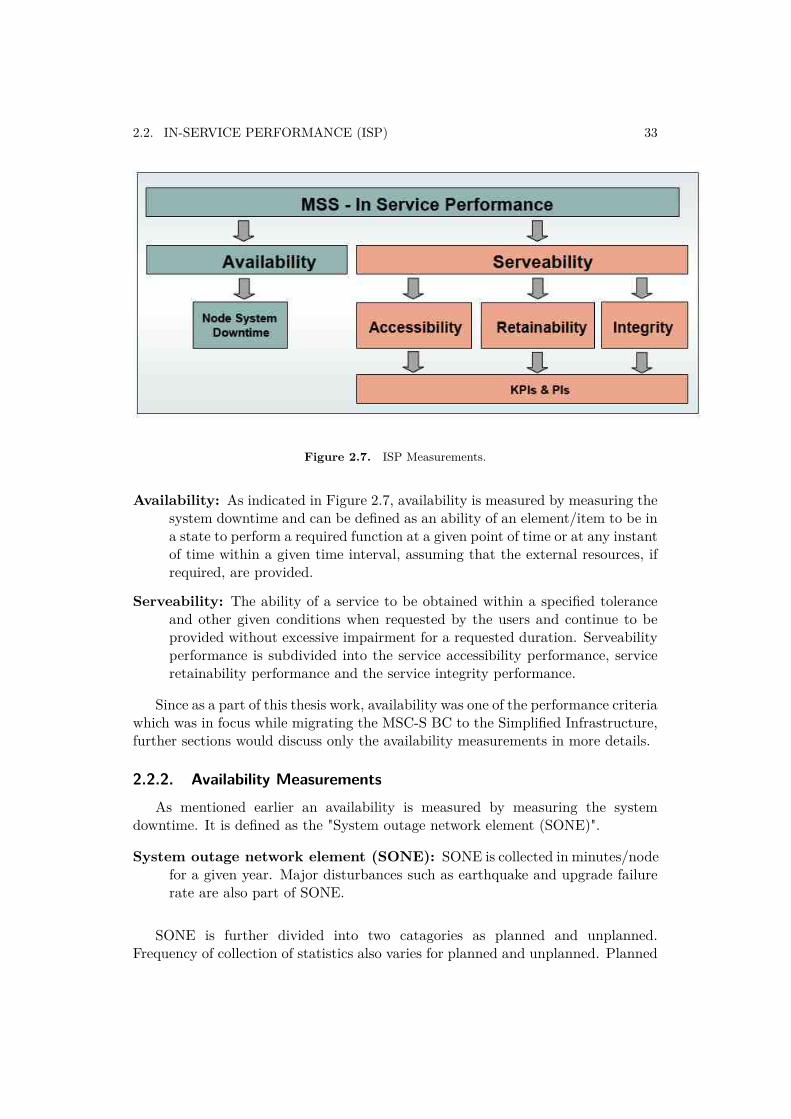
Figure 2.7. ISP Measurements.
Availability: As indicated in Figure 2.7, availability is measured by measuring thesystem downtime and can be defined as an ability of an element/item to be ina state to perform a required function at a given point of time or at any instantof time within a given time interval, assuming that the external resources, ifrequired, are provided.
Serveability: The ability of a service to be obtained within a specified toleranceand other given conditions when requested by the users and continue to beprovided without excessive impairment for a requested duration. Serveabilityperformance is subdivided into the service accessibility performance, serviceretainability performance and the service integrity performance.
Since as a part of this thesis work, availability was one of the performance criteriawhich was in focus while migrating the MSC-S BC to the Simplified Infrastructure,further sections would discuss only the availability measurements in more details.
2.2.2. Availability MeasurementsAs mentioned earlier an availability is measured by measuring the system
downtime. It is defined as the "System outage network element (SONE)".
System outage network element (SONE): SONE is collected in minutes/nodefor a given year. Major disturbances such as earthquake and upgrade failurerate are also part of SONE.
SONE is further divided into two catagories as planned and unplanned.Frequency of collection of statistics also varies for planned and unplanned. Planned
34 CHAPTER 2. GENERAL BACKGROUND
SONE is collected only once in a year where as unplanned SONE is collected everymonth.
Planned SONE: Under a planned only SONE one category exist and the collectedstatistics under this catagory is named as PLM, which stands for planned-manual and it includes downtime causes for the software upgrade, softwareupdate and the hardware upgrade or update.
Unplanned SONE: Unplanned is further divided into following four catagories.In the current thesis scope, only an automatic type of unplanned SONE wasconsidered during analysis and evaluation of the results.
Automatic (AUT): This type caters for the downtime causes due tosoftware faults and/or configuration faults which makes the bladecompletely down. Also the system recovers from the fault on it’s owneither by restart or reload. Network or link faults are not counted heresince they make only part of the blade to go down and not the completeblade fails.
Manual (UPM): This type caters for downtime causes where an automaticrecovery has failed and an operator intervention is needed. It alsoconsiders the cases where the automatic recovery is not triggered.Examples include hanging of devices, hanging of software etc.
CEF-Eric: This means complete exchange failure due to an Ericsson equip-ment.
CEF-Cust: This means complete exchange failure due to the customer’s ownequipment.
2.3. SI Prototype Summary
2.3.1. Overview
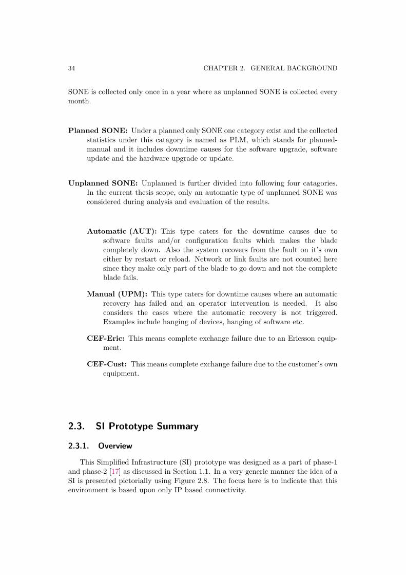
This Simplified Infrastructure (SI) prototype was designed as a part of phase-1and phase-2 [17] as discussed in Section 1.1. In a very generic manner the idea of aSI is presented pictorially using Figure 2.8. The focus here is to indicate that thisenvironment is based upon only IP based connectivity.
2.3. SI PROTOTYPE SUMMARY 35
Figure 2.8. Generic view of the Simplified Infrastructure (SI).
If applied to the MSC-S BC, the same idea will look like as presented with thehelp of Figure 2.9.
36 CHAPTER 2. GENERAL BACKGROUND
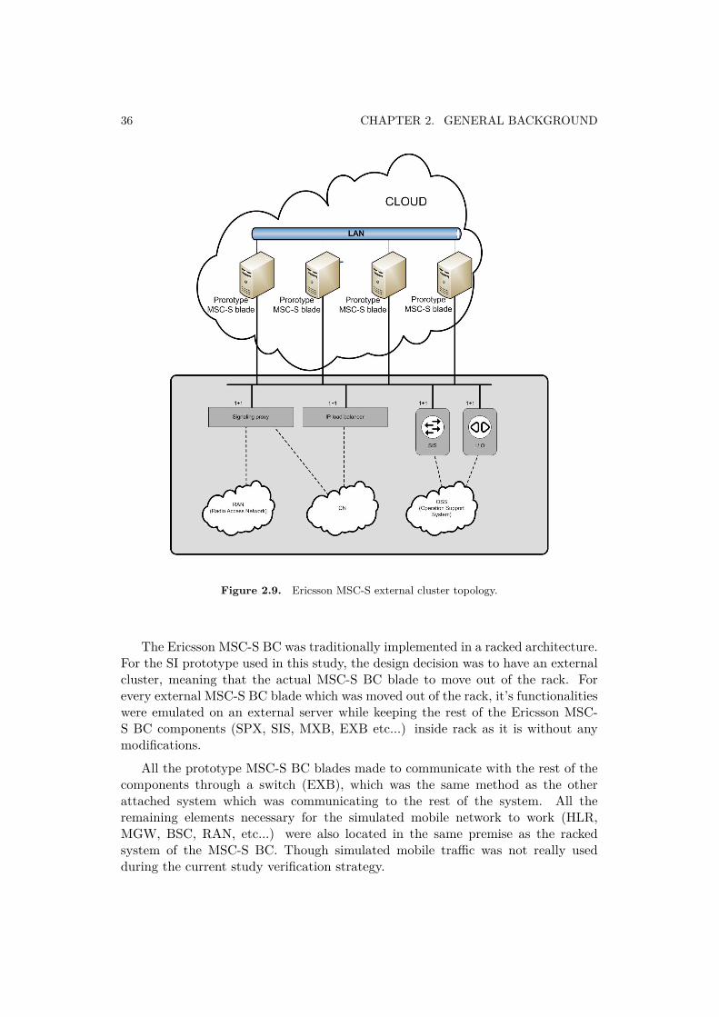
Figure 2.9. Ericsson MSC-S external cluster topology.
The Ericsson MSC-S BC was traditionally implemented in a racked architecture.For the SI prototype used in this study, the design decision was to have an externalcluster, meaning that the actual MSC-S BC blade to move out of the rack. Forevery external MSC-S BC blade which was moved out of the rack, it’s functionalitieswere emulated on an external server while keeping the rest of the Ericsson MSC-S BC components (SPX, SIS, MXB, EXB etc...) inside rack as it is without anymodifications.
All the prototype MSC-S BC blades made to communicate with the rest of thecomponents through a switch (EXB), which was the same method as the otherattached system which was communicating to the rest of the system. All theremaining elements necessary for the simulated mobile network to work (HLR,MGW, BSC, RAN, etc...) were also located in the same premise as the rackedsystem of the MSC-S BC. Though simulated mobile traffic was not really usedduring the current study verification strategy.
2.3. SI PROTOTYPE SUMMARY 37
Also, in order to simulate the network characteristic of a real cloud environmentwithin this topology, various tests were conducted introducing network penalties,such as packet loss and delay. Exact test details, configurations, and results of thesetests could be found in Chapter-3 of the previous work [17].
Additionally the different modules in this prototype were designed by followinga bottom-up approach in terms of complexity so that issues that might arise couldbe tackled in a systematic manner.
2.3.2. Verification Environment in Prototype
The verification environment consisted of various elements. These elements werescattered over three different Ericsson labs, two located in Stockholm and anotherin Montreal but as a part of the current thesis work only the Stockholm lab testenvironment was utilized. Hence only these labs test environment is covered inthis section. All the three labs were connected to each other through the Ericssoninternal network.
Stockholm Laboratory A: The Stockholm Laboratory A was one of the labo-ratories used during the tests. This laboratory contained the actual rackedEricsson MSC-S BC implementation with all of its components along with theseveral machines that run traffic generators to emulate the mobile traffic.
Also, in order to realize the topology of an external cluster as described above,additional machines were necessary. As per their functions the names givenwere: Bridge and Cloud machines.
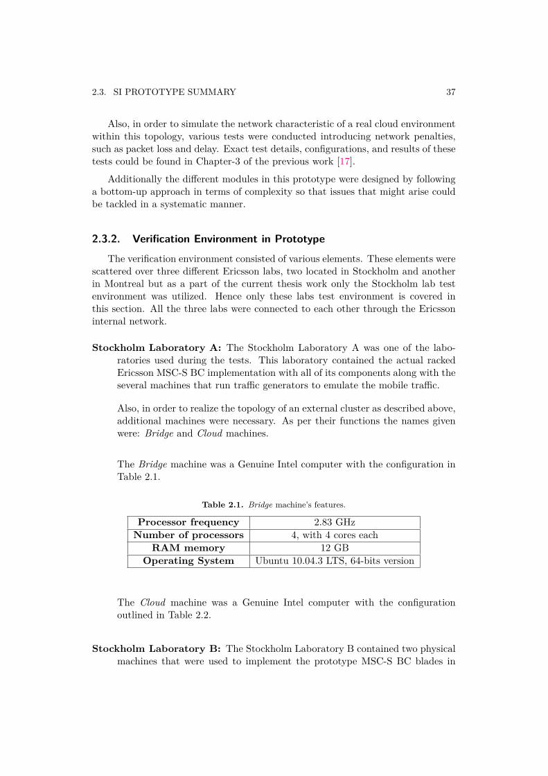
The Bridge machine was a Genuine Intel computer with the configuration inTable 2.1.
Table 2.1. Bridge machine’s features.
Processor frequency 2.83 GHzNumber of processors 4, with 4 cores each
RAM memory 12 GBOperating System Ubuntu 10.04.3 LTS, 64-bits version
The Cloud machine was a Genuine Intel computer with the configurationoutlined in Table 2.2.
Stockholm Laboratory B: The Stockholm Laboratory B contained two physicalmachines that were used to implement the prototype MSC-S BC blades in
38 CHAPTER 2. GENERAL BACKGROUND
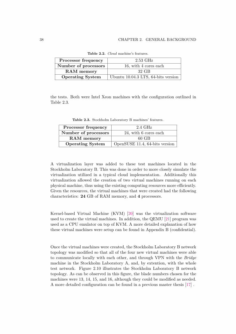
Table 2.2. Cloud machine’s features.
Processor frequency 2.53 GHzNumber of processors 16, with 4 cores each
RAM memory 32 GBOperating System Ubuntu 10.04.3 LTS, 64-bits version
the tests. Both were Intel Xeon machines with the configuration outlined inTable 2.3.
Table 2.3. Stockholm Laboratory B machines’ features.
Processor frequency 2.4 GHzNumber of processors 24, with 6 cores each
RAM memory 60 GBOperating System OpenSUSE 11.4, 64-bits version
A virtualization layer was added to these test machines located in theStockholm Laboratory B. This was done in order to more closely simulate thevirtualization utilized in a typical cloud implementation. Additionally thisvirtualization allowed the creation of two virtual machines running on eachphysical machine, thus using the existing computing resources more efficiently.Given the resources, the virtual machines that were created had the followingcharacteristics: 24 GB of RAM memory, and 4 processors.
Kernel-based Virtual Machine (KVM) [20] was the virtualization softwareused to create the virtual machines. In addition, the QEMU [21] program wasused as a CPU emulator on top of KVM. A more detailed explanation of howthese virtual machines were setup can be found in Appendix B (confidential).
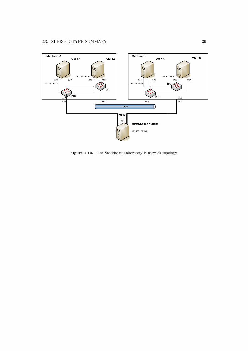
Once the virtual machines were created, the Stockholm Laboratory B networktopology was modified so that all of the four new virtual machines were ableto communicate locally with each other, and through VPN with the Bridgemachine in the Stockholm Laboratory A, and, by extention, with the wholetest network. Figure 2.10 illustrates the Stockholm Laboratory B networktopology. As can be observed in this figure, the blade numbers chosen for themachines were 13, 14, 15, and 16, although they could be modified as needed.A more detailed configuration can be found in a previous master thesis [17] .
2.3. SI PROTOTYPE SUMMARY 39
Figure 2.10. The Stockholm Laboratory B network topology.

Chapter 3
Evaluation
This chapter describes the evaluation part of this thesis project. In the beginninga discussion about how a theoretical study was carried out is presented (Section 3.1).It is followed by the various findings of this theoretical study (Section 3.2). Next,an individual finding analysis along with a suitable proposal for each finding ispresented (Section 3.4). Further to that a test strategy and the designed testcases are discussed for verifying important proposals of the study. Then the testexecution, the test results and the challenges encountered during test execution areclearly stated (Section 3.4.3). In the end an evaluation summary is presented.
3.1. Approach for Theoretical Study
Since the higher goal of this thesis project was to find out about therequirements, which enable the migration of one of the Ericsson’s platform to aSimplified Infrastructure without causing any impact on it’s in-service performance,the main focus area of the theoretical study was derived by understanding thefunctions directly or indirectly contributing to the platform’s in-service performance.With this idea in mind important concepts of the in-service performance as wellas an overall architecture of the platform (MSC-S BC in this case) was studiedvery thoroughly (considering both the HW and SW functions). Exact detailsare presented further, where Section 3.1.1 talks about the functional areas of theplatform, which comes into picture with respect to in-service performance, andSection 3.1.2 sheds some light on the current design of the platform and what itmeans for such a platform to migrate to a Simplified Infrastructure with no impacton it’s in-service performance.
3.1.1. Analysis from ISP Perspective
From the detailed study of the in-service performance concepts, it can be saidthat there exist a very good ISP statistics internal to Ericsson. Hence detailed
41
42 CHAPTER 3. EVALUATION
analysis of those statistics proven to be very helpful in deriving different functionalareas connected to the in-service performance of the the platform. As a part such ananalysis, it can also be said that there were mainly two different types of downtime,which could affect availability and hence the in-service performance of the platform.As discussed earlier in Chapter 2 of Section 2.2.2, they were mainly the plannedand the unplanned downtime.
• Planned Downtime: It is mainly influenced by the way update and upgradeprocedures of the platform are designed and carried out in the field.
• Unplanned Downtime: The ability of the platform to recover from anunexpected fault(s) in real time would highly influence the unplanneddowntime and hence the total availability of the node itself. The ability of theplatform to recover from faults (either through automatic or manual type ofrecovery) is goverend by the design of Fault Tolerant Architecture (FTA) ofthe platform (both the cluster level as well as the blade level FTA).
3.1.1.1 Fault Tolerant Architecture
From the detailed analysis, it can be said that the fault detection, the faultrecovery and the logging together consistutes the Fault Tolerant Architecture of theplatform. Hence these were the three catagories of functions which were particularlyof interest during an analysis.
Phase-1 and 2 of the Simplified Infrastructure study [17] mainly focussed onstudying the performance of the cluster level fault tolerance while migrating to aSimplified Infrastructure, and it indicated promising results. The next step wasto do an analysis for the blade level fault tolerance, and during the current study(Phase-3) it became the prime focus area.
To have a systematic analysis, the blade level fault tolerance was further dividedinto the following two categories. They were identified as Internal and External.
• Internal (local to the blade) : Internal mainly covered the recovery mechanismsand the connected functions local to the blade and it was further divided intothree groups as follows. They were mainly,
a) Initial Startb) Large Restartc) Cloning
• External (outside support/functions for recoverying the suspected faultyblade) : External, mainly covered recovery functions executed with the helpof external interfaces/functions.
3.1. APPROACH FOR THEORETICAL STUDY 43
3.1.2. Current System Design Perspective
The detailed study of the platform indicated that many important systemfunctions including different groups of fault tolerant functions such as the faultdetection, the fault recovery and the logging were closely coupled to it’s existingHW. It was also observed that such a close couplings had also increased the numberof interfaces, both IP based an NON-IP based, which became mandatory to utilizein order to complete the connectivity for expected operation of it’s fault tolerantarchitecture. Additonally these interfaces had also created more than one wayto access some of the most crucial functions as well as the data storages, whoseconsistancy played a crucial role for every decision taken by the fault tolerantarchitecture of the platform (for both the blade level as well as the cluster levelfault handling).
Since the Simplified Infrastructure could provide only IP based connectivitybetween all of it’s components, this became a principle differentiator while doingan analysis of the various fault tolerant functions of the blade. This also became agoverning factor for further analysis of the results.
Hence while carrying out this study, only those interfaces and the fault toelrantfunctions were considered, which were making use of the NON-IP based connection.They were analyzed with respect to their unavailability within the SimplifiedInfrastructure and it was firmly believed that this methodology would help inanalyzing an impact on the platform’s in-service performance for such a migration.
Figure 3.1 and Figure 3.2 demonstrate such a close coupling between varioussystem functions of two MSC-S BC blades (BC0 and BC1 in this case) and it’sinfrastructure blades (MXB and SIS in this case).
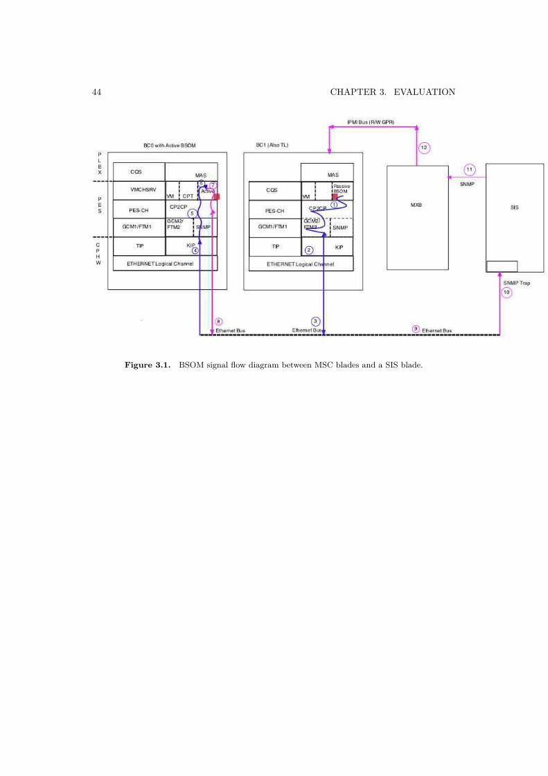
44 CHAPTER 3. EVALUATION
Figure 3.1. BSOM signal flow diagram between MSC blades and a SIS blade.
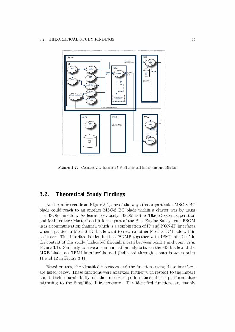
3.2. THEORETICAL STUDY FINDINGS 45
Figure 3.2. Connectivity between CP Blades and Infrastructure Blades.
3.2. Theoretical Study Findings
As it can be seen from Figure 3.1, one of the ways that a particular MSC-S BCblade could reach to an another MSC-S BC blade within a cluster was by usingthe BSOM function. As learnt previously, BSOM is the "Blade System Operationand Maintenance Master" and it forms part of the Plex Engine Subsystem. BSOMuses a communication channel, which is a combination of IP and NON-IP interfaceswhen a particular MSC-S BC blade want to reach another MSC-S BC blade withina cluster. This interface is identified as "SNMP together with IPMI interface" inthe context of this study (indicated through a path between point 1 and point 12 inFigure 3.1). Similarly to have a communication only between the SIS blade and theMXB blade, an "IPMI interface" is used (indicated through a path between point11 and 12 in Figure 3.1).
Based on this, the identified interfaces and the functions using these interfacesare listed below. These functions were analyzed further with respect to the impactabout their unavailability on the in-service performance of the platform aftermigrating to the Simplified Infrastructure. The identified functions are mainly
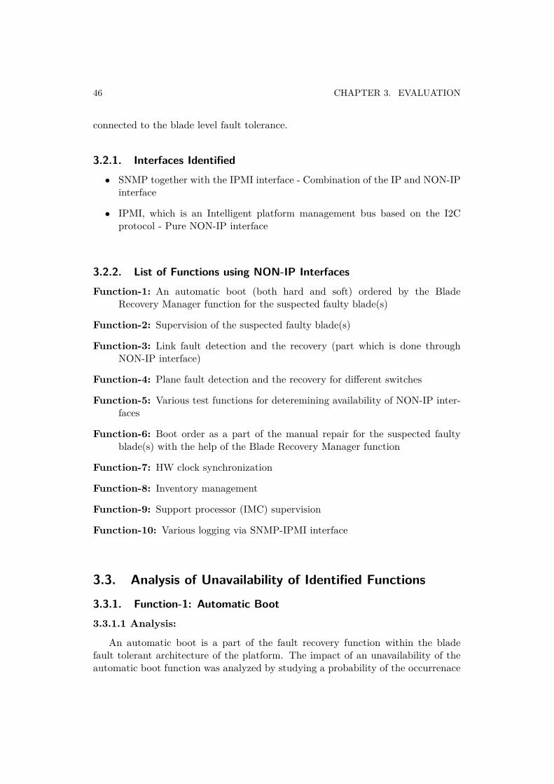
46 CHAPTER 3. EVALUATION
connected to the blade level fault tolerance.
3.2.1. Interfaces Identified• SNMP together with the IPMI interface - Combination of the IP and NON-IP
interface
• IPMI, which is an Intelligent platform management bus based on the I2Cprotocol - Pure NON-IP interface
3.2.2. List of Functions using NON-IP InterfacesFunction-1: An automatic boot (both hard and soft) ordered by the Blade
Recovery Manager function for the suspected faulty blade(s)
Function-2: Supervision of the suspected faulty blade(s)
Function-3: Link fault detection and the recovery (part which is done throughNON-IP interface)
Function-4: Plane fault detection and the recovery for different switches
Function-5: Various test functions for deteremining availability of NON-IP inter-faces
Function-6: Boot order as a part of the manual repair for the suspected faultyblade(s) with the help of the Blade Recovery Manager function
Function-7: HW clock synchronization
Function-8: Inventory management
Function-9: Support processor (IMC) supervision
Function-10: Various logging via SNMP-IPMI interface
3.3. Analysis of Unavailability of Identified Functions
3.3.1. Function-1: Automatic Boot3.3.1.1 Analysis:
An automatic boot is a part of the fault recovery function within the bladefault tolerant architecture of the platform. The impact of an unavailability of theautomatic boot function was analyzed by studying a probability of the occurrenace
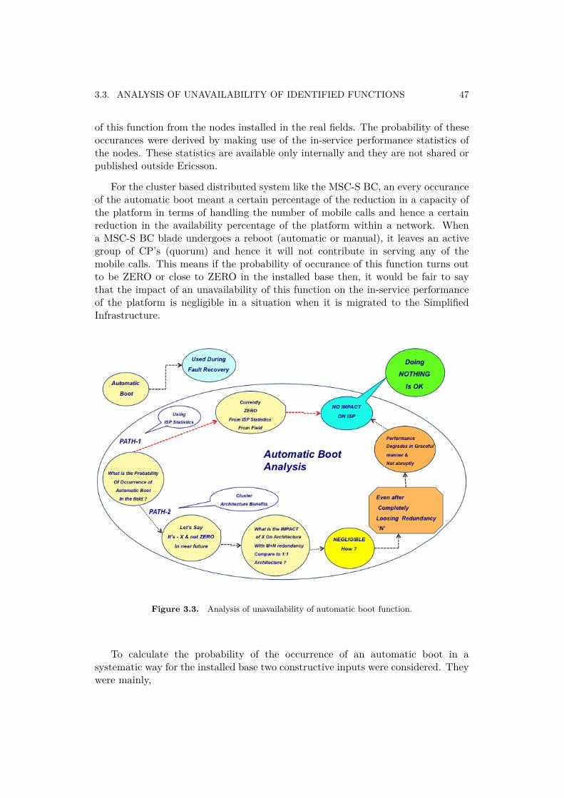
3.3. ANALYSIS OF UNAVAILABILITY OF IDENTIFIED FUNCTIONS 47
of this function from the nodes installed in the real fields. The probability of theseoccurances were derived by making use of the in-service performance statistics ofthe nodes. These statistics are available only internally and they are not shared orpublished outside Ericsson.
For the cluster based distributed system like the MSC-S BC, an every occuranceof the automatic boot meant a certain percentage of the reduction in a capacity ofthe platform in terms of handling the number of mobile calls and hence a certainreduction in the availability percentage of the platform within a network. Whena MSC-S BC blade undergoes a reboot (automatic or manual), it leaves an activegroup of CP’s (quorum) and hence it will not contribute in serving any of themobile calls. This means if the probability of occurance of this function turns outto be ZERO or close to ZERO in the installed base then, it would be fair to saythat the impact of an unavailability of this function on the in-service performanceof the platform is negligible in a situation when it is migrated to the SimplifiedInfrastructure.
Figure 3.3. Analysis of unavailability of automatic boot function.
To calculate the probability of the occurrence of an automatic boot in asystematic way for the installed base two constructive inputs were considered. Theywere mainly,

48 CHAPTER 3. EVALUATION
ISP Statistics collected as a part of Events from the Installed Base: By count-ing number of occurance of an automatic boot with the help of available in-service performance statistics collected regularly from the currently installedbase.
Benefits of a Clustered Architecture: By studying the benefits of the clusterarchitecture having an M+N redundency principle, where the impact ofloosing a single blade on the availability of the platform due to an automaticboot is ZERO and loosing more than one number of blades was considerednegligible, since the platform’s capacity to handle the total number of mobilecalls reduces in a very graceful manner.
The graphical representation of the same is shown using Figure 3.3.
3.3.1.2 Discussions:
As it can be seen from Figure 3.3, the outcome for the two inputs considered foran analysis of the unavailability of an automatic boot function gave the followingresults.
ISP Statistics collected as a part of Events from the Installed Base: Thenumber of times the automatic boot executed in the currently installed baseturned out to be ZERO
Benefits of Cluster Architecture: Due to the M+N redundency principle, theimpact of loosing one or more MSC-S BC blades due to an automatic bootcould be considered negligible.
3.3.1.3 Proposal:
Due to such outcome on the considered inputs it can be concluded that the im-pact of unavailability of an automatic boot function due to the platform’s migrationto the Simplified Infrastructure on it’s in-service performance is negligible. Henceone of the alternatives could be not to take any action for unavailability and tocontinue to have the system without the automatic boot function after migration.
3.3.2. Function-2: Supervision of Suspected Faulty Blade
3.3.2.1 Analysis:
This function is a part of the fault recovery as well as the logging group withinthe blade level fault tolerant architecture. The impact of this function was analyzedby understanding the contribution made by this function during the blade recovery.As it can be seen from Figure 3.4, the function necessarily served two functions.They were mainly,
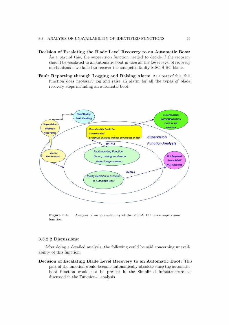
3.3. ANALYSIS OF UNAVAILABILITY OF IDENTIFIED FUNCTIONS 49
Decision of Escalating the Blade Level Recovery to an Automatic Boot:As a part of this, the supervision function needed to decide if the recoveryshould be escalated to an automatic boot in case all the lower level of recoverymechanisms have failed to recover the susepcted faulty MSC-S BC blade.
Fault Reporting through Logging and Raising Alarm As a part of this, thisfunction does necessary log and raise an alarm for all the types of bladerecovery steps including an automatic boot.
Figure 3.4. Analysis of an unavailability of the MSC-S BC blade supervisionfunction.
3.3.2.2 Discussions:
After doing a detailed analysis, the following could be said concerning unavail-ability of this function.
Decision of Escalating Blade Level Recovery to an Automatic Boot: Thispart of the function would become automatically obsolete since the automaticboot function would not be present in the Simplified Infrastructure asdiscussed in the Function-1 analysis.
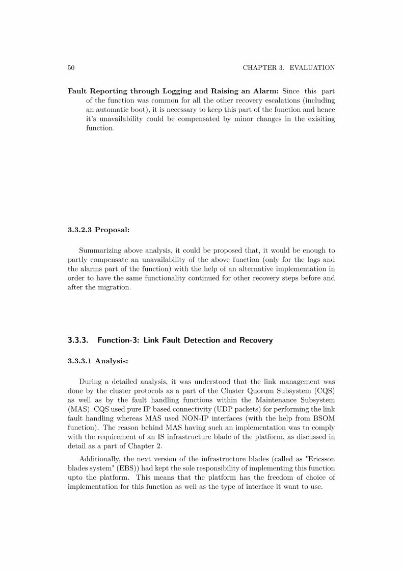
50 CHAPTER 3. EVALUATION
Fault Reporting through Logging and Raising an Alarm: Since this partof the function was common for all the other recovery escalations (includingan automatic boot), it is necessary to keep this part of the function and henceit’s unavailability could be compensated by minor changes in the exisitingfunction.
3.3.2.3 Proposal:
Summarizing above analysis, it could be proposed that, it would be enough topartly compensate an unavailability of the above function (only for the logs andthe alarms part of the function) with the help of an alternative implementation inorder to have the same functionality continued for other recovery steps before andafter the migration.
3.3.3. Function-3: Link Fault Detection and Recovery
3.3.3.1 Analysis:
During a detailed analysis, it was understood that the link management wasdone by the cluster protocols as a part of the Cluster Quorum Subsystem (CQS)as well as by the fault handling functions within the Maintenance Subsystem(MAS). CQS used pure IP based connectivity (UDP packets) for performing the linkfault handling whereas MAS used NON-IP interfaces (with the help from BSOMfunction). The reason behind MAS having such an implementation was to complywith the requirement of an IS infrastructure blade of the platform, as discussed indetail as a part of Chapter 2.
Additionally, the next version of the infrastructure blades (called as "Ericssonblades system" (EBS)) had kept the sole responsibility of implementing this functionupto the platform. This means that the platform has the freedom of choice ofimplementation for this function as well as the type of interface it want to use.
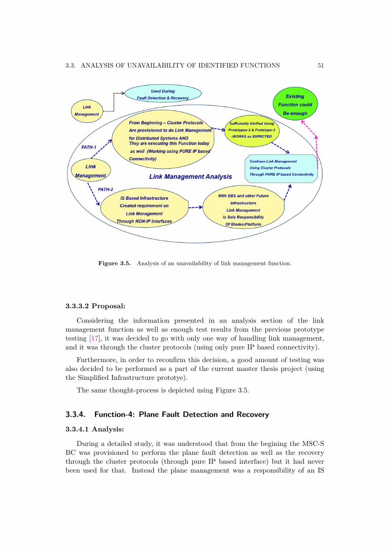
3.3. ANALYSIS OF UNAVAILABILITY OF IDENTIFIED FUNCTIONS 51
Figure 3.5. Analysis of an unavailability of link management function.
3.3.3.2 Proposal:
Considering the information presented in an analysis section of the linkmanagement function as well as enough test results from the previous prototypetesting [17], it was decided to go with only one way of handling link management,and it was through the cluster protocols (using only pure IP based connectivity).
Furthermore, in order to reconfirm this decision, a good amount of testing wasalso decided to be performed as a part of the current master thesis project (usingthe Simplified Infrastructure prototye).
The same thought-process is depicted using Figure 3.5.
3.3.4. Function-4: Plane Fault Detection and Recovery
3.3.4.1 Analysis:
During a detailed study, it was understood that from the begining the MSC-SBC was provisioned to perform the plane fault detection as well as the recoverythrough the cluster protocols (through pure IP based interface) but it had neverbeen used for that. Instead the plane management was a responsibility of an IS
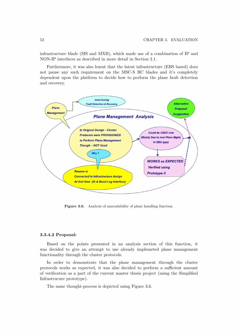
52 CHAPTER 3. EVALUATION
infrastructure blade (SIS and MXB), which made use of a combination of IP andNON-IP interfaces as described in more detail in Section 2.1.
Furthermore, it was also learnt that the latest infrastructure (EBS based) doesnot pause any such requirement on the MSC-S BC blades and it’s completelydependent upon the platform to decide how to perform the plane fault detectionand recovery.
Figure 3.6. Analysis of unavailability of plane handling function.
3.3.4.2 Proposal:
Based on the points presented in an analysis section of this function, itwas decided to give an attempt to use already implemeted plane managementfunctionality through the cluster protocols.
In order to demonstrate that the plane management through the clusterprotocols works as expected, it was also decided to perform a sufficient amountof verification as a part of the current master thesis project (using the SimplifiedInfrastrucure prototype).
The same thought-process is depicted using Figure 3.6.
3.3. ANALYSIS OF UNAVAILABILITY OF IDENTIFIED FUNCTIONS 53
3.3.5. Remaining functions: Function-5 to Function-10
3.3.5.1 Analysis:
During this study the functions identified under function number 5 to 10 (listedunder Section 3.2.2) were not directly part of the Fault Tolerant Architecture of theblade and hence were not studied as a part of this study. All these functions arealso indicated using Figure 3.7.
Figure 3.7. Analysis of unavailability for rest of the functions.
3.3.5.2 Proposal:
Even though these functions did not directly form the part of the Fault ToleranceArchitecture (neither at the cluster level or at the blade level), they were stillidentified and considered as crucial ones with respect to the complete platform andhence they would require a further study in order to provide an analysis similar tothe one provided for Function-1 to Function-5.
3.3.6. Summary on Proposals for Different Functions
The summary of the different proposals is presented in Figure 3.8.
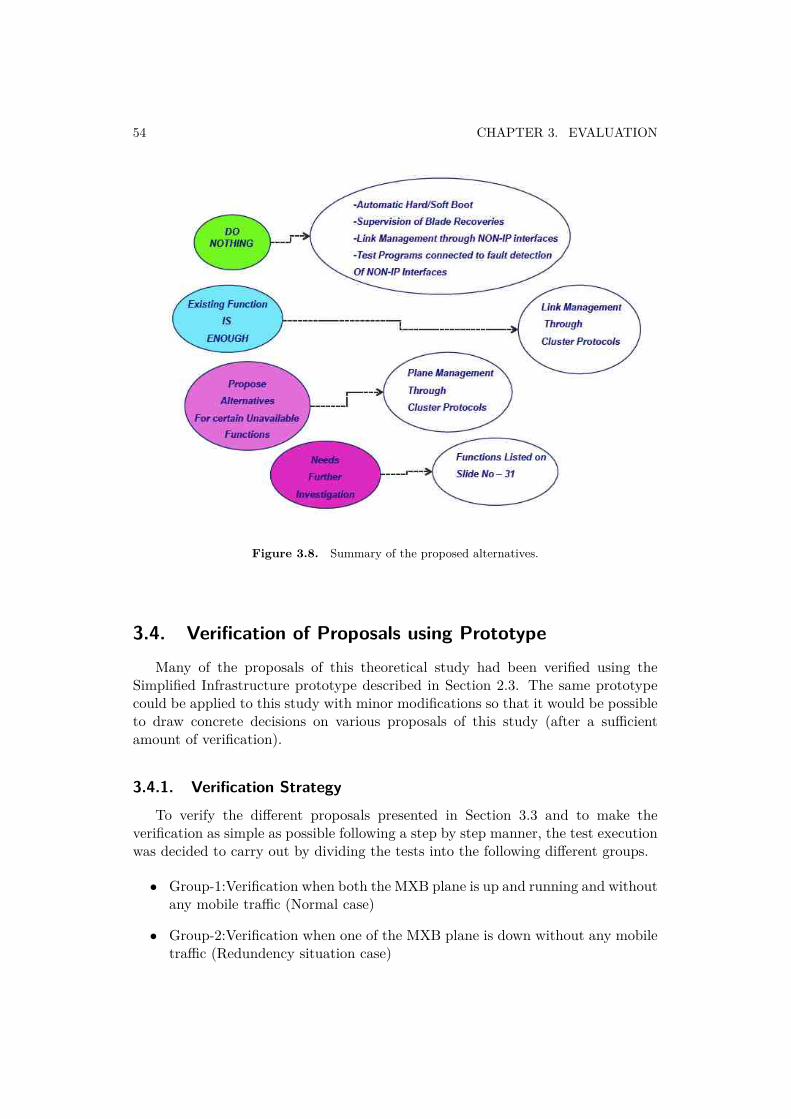
54 CHAPTER 3. EVALUATION
Figure 3.8. Summary of the proposed alternatives.
3.4. Verification of Proposals using PrototypeMany of the proposals of this theoretical study had been verified using the
Simplified Infrastructure prototype described in Section 2.3. The same prototypecould be applied to this study with minor modifications so that it would be possibleto draw concrete decisions on various proposals of this study (after a sufficientamount of verification).
3.4.1. Verification Strategy
To verify the different proposals presented in Section 3.3 and to make theverification as simple as possible following a step by step manner, the test executionwas decided to carry out by dividing the tests into the following different groups.
• Group-1:Verification when both the MXB plane is up and running and withoutany mobile traffic (Normal case)
• Group-2:Verification when one of the MXB plane is down without any mobiletraffic (Redundency situation case)
3.4. VERIFICATION OF PROPOSALS USING PROTOTYPE 55
• Group-3:Verification using the test cases of Group-1 and Group-2, initiallywith a very low mobile traffic (GSM and UMTS type) and later with the highmobile traffic
Also as a part of the verification strategy, whenever the problems wereencountered during the execution of tests and if an initial troubleshooting pointedtowards the prototyping problems, the required changes were done with the helpof the technical supervisors of this thesis project at Ericsson. In general theprototyping problems were kept out of the scope from the main findings of thisstudy and hence they are not discussed in this thesis report.
3.4.2. Test Case Description
For each of the group listed in Section 3.4.1, a specific set of test cases weredesigned. They were divided into two main catagories depending upon theirpurpose. They were mainly,
• Cluster Scalability Tests
• Fault Recovery Tests
3.4.2.1 Cluster Scalability Tests
As a part of this test group, the scalability of the MSC-S BC was verified. Thescalability allowed an addition and the removal of an individual MSC-S BC blade toand from an existing cluster with almost no cost on the performance of the system.
Since this formed the very basic functionality of the MSC-S BC, this group oftests were verified in a previous master thesis (in a very exhausitive way) and hadalso been verified as a part of the current thesis in order to make sure that sucha basic functionality works as expected when the MSC-S BC gets migrated to theSimplified Infrastructure. The group of test cases designed as a part of this catagorywere,
Test Case-1: Forming an MSC-S BC Cluster from Scratch
Test Case-2: MSC-S BC Blade Addition - Adding one or more MSC-S BC bladesto an active quorum
Test Case-3: MSC-S BC Blade Removal - Removing one or more MSC-S BCblades from an active quorum

56 CHAPTER 3. EVALUATION
3.4.2.2 Fault Recovery Tests
In the MSC-S BC, the cluster protocols included various recovery schemes thatwill help the cluster to recover from different fault situations as previously mentionedin Section 2.1.3. The cluster fault tolerance included functions such as,
• Cluster Formation
• Cluster Reformation/Modification - Due to an addition and removal of theblades
• Cluster Fault Tolerance - This include functions such as multiple link and/orblade faults, AQR and partition handling
• SW-HW upgrade
In order to verify all the suggestions proposed in the theoretical study(Section 3.3.1, Section 3.3.2, Section 3.3.3, Section 3.3.4) the following set of testcases were designed. It was also understood that the recovery scheme was differentdepending on whether the fault is temporary (short-time fault) or permanent one(long-time fault). Therefore the designed test cases covered the following differenttypes of tests for each type of link fault.
Test Case-4: Single Link Fault - For both temporary and permanent types offaults
Test Case-5: Multiple Link Fault - For both temporary and permanent types offaults
Test Case-6: Single Plane Fault - One of the plane of the MXB goes faulty
3.4.3. Test ExecutionAs a part of this section, the test execution procedure is presented for both
catagories of the test cases, which cover the cluster scalability tests and the faultrecovery tests.
3.4.3.1 Cluster Scalability Tests - Execution
1) Formation of a Cluster from Scratch
The cluster is formed by adding the MSC-S BC blade one after the other usinga procedure described in section:MSC-S blade addition. This loop is repeated untillall the required blades are added to the cluster.
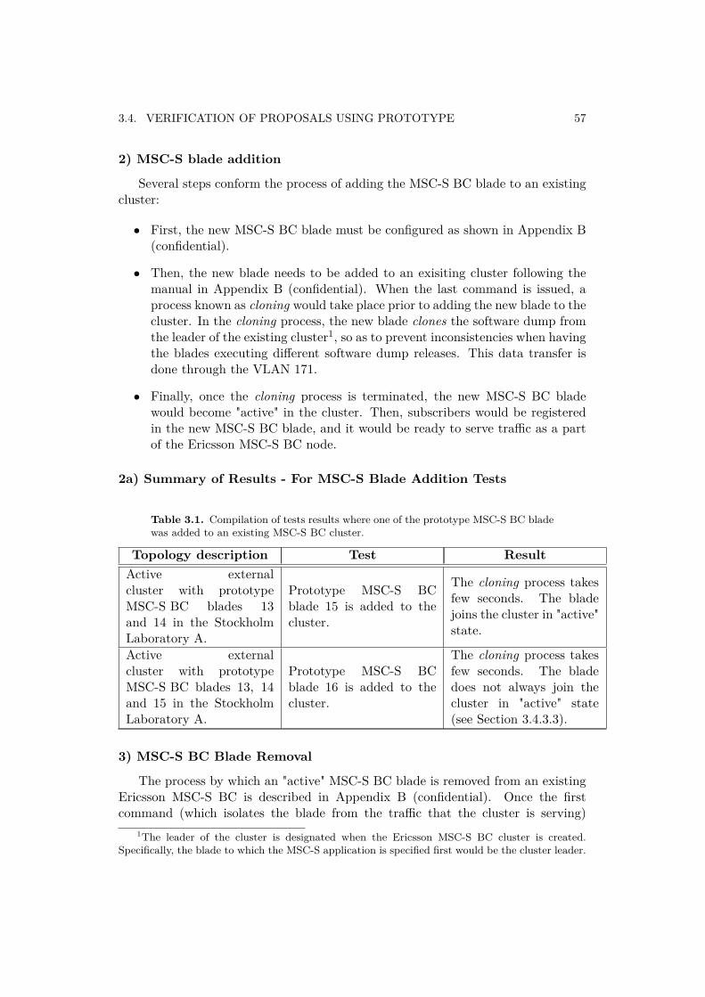
3.4. VERIFICATION OF PROPOSALS USING PROTOTYPE 57
2) MSC-S blade addition
Several steps conform the process of adding the MSC-S BC blade to an existingcluster:
• First, the new MSC-S BC blade must be configured as shown in Appendix B(confidential).
• Then, the new blade needs to be added to an exisiting cluster following themanual in Appendix B (confidential). When the last command is issued, aprocess known as cloning would take place prior to adding the new blade to thecluster. In the cloning process, the new blade clones the software dump fromthe leader of the existing cluster1, so as to prevent inconsistencies when havingthe blades executing different software dump releases. This data transfer isdone through the VLAN 171.
• Finally, once the cloning process is terminated, the new MSC-S BC bladewould become "active" in the cluster. Then, subscribers would be registeredin the new MSC-S BC blade, and it would be ready to serve traffic as a partof the Ericsson MSC-S BC node.
2a) Summary of Results - For MSC-S Blade Addition Tests
Table 3.1. Compilation of tests results where one of the prototype MSC-S BC bladewas added to an existing MSC-S BC cluster.
Topology description Test ResultActive externalcluster with prototypeMSC-S BC blades 13and 14 in the StockholmLaboratory A.
Prototype MSC-S BCblade 15 is added to thecluster.
The cloning process takesfew seconds. The bladejoins the cluster in "active"state.
Active externalcluster with prototypeMSC-S BC blades 13, 14and 15 in the StockholmLaboratory A.
Prototype MSC-S BCblade 16 is added to thecluster.
The cloning process takesfew seconds. The bladedoes not always join thecluster in "active" state(see Section 3.4.3.3).
3) MSC-S BC Blade Removal
The process by which an "active" MSC-S BC blade is removed from an existingEricsson MSC-S BC is described in Appendix B (confidential). Once the firstcommand (which isolates the blade from the traffic that the cluster is serving)
1The leader of the cluster is designated when the Ericsson MSC-S BC cluster is created.Specifically, the blade to which the MSC-S application is specified first would be the cluster leader.
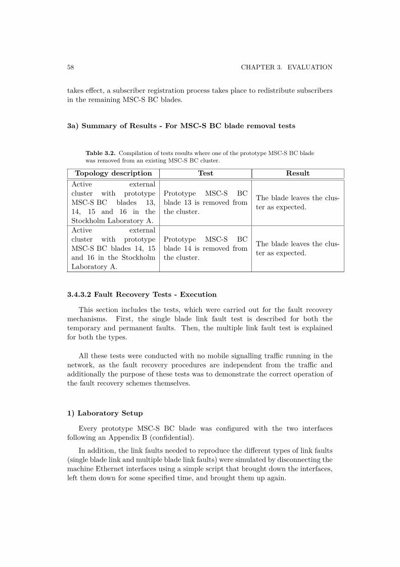
58 CHAPTER 3. EVALUATION
takes effect, a subscriber registration process takes place to redistribute subscribersin the remaining MSC-S BC blades.
3a) Summary of Results - For MSC-S BC blade removal tests
Table 3.2. Compilation of tests results where one of the prototype MSC-S BC bladewas removed from an existing MSC-S BC cluster.
Topology description Test ResultActive externalcluster with prototypeMSC-S BC blades 13,14, 15 and 16 in theStockholm Laboratory A.
Prototype MSC-S BCblade 13 is removed fromthe cluster.
The blade leaves the clus-ter as expected.
Active externalcluster with prototypeMSC-S BC blades 14, 15and 16 in the StockholmLaboratory A.
Prototype MSC-S BCblade 14 is removed fromthe cluster.
The blade leaves the clus-ter as expected.
3.4.3.2 Fault Recovery Tests - Execution
This section includes the tests, which were carried out for the fault recoverymechanisms. First, the single blade link fault test is described for both thetemporary and permanent faults. Then, the multiple link fault test is explainedfor both the types.
All these tests were conducted with no mobile signalling traffic running in thenetwork, as the fault recovery procedures are independent from the traffic andadditionally the purpose of these tests was to demonstrate the correct operation ofthe fault recovery schemes themselves.
1) Laboratory Setup
Every prototype MSC-S BC blade was configured with the two interfacesfollowing an Appendix B (confidential).
In addition, the link faults needed to reproduce the different types of link faults(single blade link and multiple blade link faults) were simulated by disconnecting themachine Ethernet interfaces using a simple script that brought down the interfaces,left them down for some specified time, and brought them up again.
3.4. VERIFICATION OF PROPOSALS USING PROTOTYPE 59
2) Single Link Fault Test
The main purpose of these test was to demonstrate the correct operation of asingle blade link fault recovery schemes in the Simplified Infrastructure. The singleblade link fault situation was tested in the two different cluster configuration casesfor both the temporary and permanent faults.
2a) Temporary Fault
• First, the temporary single blade link fault recovery schemes was tested (builtusing the Stockholm Laboratory A and B). The blades that formed the clusterwere the prototype MSC-S BC blades 13, 14, 15 and 16 in the StockholmLaboratory B with the rest of the MSC-S BC components located within theStockholm Laboratory A.
• A single blade link fault of 0 to 250 seconds was reproduced in one of theblades. The link downtime value of 250 seconds was found out to be thelimit that differentiated a temporary single blade link fault from a permanentfault in the system.
• The single blade link fault was introduced in the MSC-S BC blade number 13(one of the prototype MSC-S BC blade). For every link downtime value,the MSC-S BC blade 13 restarted and once the restart was finished andthe connectivity was recovered, it rejoined the cluster in an "active" state.Therefore, the performance of the fault recovery scheme that takes over inthis situation is correct. However, due to the prototyping aspects, there weresometimes, that the prototype MSC-S BC blade came back to the cluster ina "passive" state instead of an "active" state. This issue is the same that isclarified in the Section 3.4.3.3.
2b) Permanent Fault
The blades that formed the cluster were the prototype MSC-S BC blades 13,14, 15 and 16. While a single link fault with the link downtimes higher than 250seconds (up to 300 seconds) was reproduced in one of the blades.
• The single blade link fault was introduced in the prototype MSC-S BC bladenumber 15 (located in the Stockholm Laboratory B). Independently of thelink downtime value, the prototype MSC-S BC blade 15 restarted as expectedand, once the restart was finished and 250 seconds passed, it switched to the"recovery" state. Finally, when the link fault was removed and the connectivityrecovered between the rest of the cluster and the faulty blade, the prototypeMSC-S BC blades 15 automatically started a cloning process to rejoin thecluster, finally coming back in an "active" state. Therefore the performanceof the fault recovery scheme that takes over in this situation is correct.
60 CHAPTER 3. EVALUATION
• The same procedure was repeated for the MSC-S BC blades 13, 14 and 16as well. They each recovered in the same manner as described above for theMSC-S BC blade 15.
3) Multiple Link Fault Test
These tests were meant to prove the correct operation for the multiple linksfault recovery schemes. The multiple links fault situation was tested for both thetemporary and permanent faults.
• The blades that formed the cluster were the prototype MSC-S BC blades 13,14, 15 and 16 in the Stockholm Laboratory B, with the rest of the MSC-S BCcomponents located within the Stockholm Laboratory A.
• A link fault of 0 to 250 seconds was reproduced in two of the blades. Thelink downtime value of 250 seconds was found out to be the limit thatdifferentiated a temporary single blade link fault from a permanent singleblade link fault in the system.
• The blade chosen to inject fault were the MSC-S BC blade number 13 and 15(two of the prototype MSC-S BC blades). For every link downtime value, boththe MSC-S BC blades (13 and 15) restarted and once the restart was finishedand the connectivity was recovered, they rejoined the cluster in an "active"state. Therefore, the performance of the fault recovery scheme that takes overin this situation is correct. However, due to the prototyping aspects, therewere sometimes that one or both the prototype MSC-S BC blade came backto the cluster in the "passive" state. This issue is the same that is clarified inSection 3.4.3.
3.4.3.3 Challenges during Test Execution
There were mainly two challenges, which arose during the test execution. Theywere mainly related to the prototyping issues and are described below in details(were outside the scope of the current thesis project. See the scope in Section 1.6).
Software Dump Consistency Check Failure: A prototyping issue was detectedwhen testing the scalability functionality of the Ericsson MSC-S BC (seeSection 3.4.3). When the cloning process, which takes place while adding aprototype MSC-S BC blade to an active cluster was delayed more than the 3minutes. This unexpected behavior was due to the fact that this SimplifiedInfrastructure prototype was not developed with the long cloning times inmind.

3.4. VERIFICATION OF PROPOSALS USING PROTOTYPE 61
MSC-S BC Blade Passive: The MSC-S application supervision function did nothave a consistent behavior when handling the prototype MSC-S BC blades.The main responsibility of this supervision function was to make a decisionabout a newly added MSC-S BC blade to the cluster about it’s activationand hence contribute to the serving traffic. But whenever a new prototypeMSC-S BC blade was added to an active cluster after a successful cloningprocess, its state was either "passive" or an "active" with no defined patternto be observed. This inconsistency also appeared when a cluster was createdwith the prototype MSC-S BC blades, where one or more of the prototypeMSC-S BC blades forming the cluster sometimes remained in the "passive"state after an activation process.

Chapter 4
Conclusions and Future Work
This chapter presents the conclusions and the future work of this master thesisproject.
4.1. ConclusionsIn this master thesis project the migration of a mobile core application to a
Simplified Infrastructure is proposed. The methodology used to achieve this wasa combination of a system study and a practical verification of the results fromthis system study using the Simplified Infrastructure prototype. Putting all theresults together, it can be firmly said that there is a potential for migrating thismobile core application to the Simplified Infrastructure. The detailed analysis alsoindicate that such a simplified infrastructure solution helps in enhancing the in-service performance provided by this type of infrastructure in comparision to usingthe native type of infrastructure. The other benefits of this solution would be to havea considerable reduction in design and maintenance costs of the core infrastructurecomponent with respect to it’s future use (mainly due to the reduction in it’scomplexity by following the proposals of the system study). Since the proposedinfrastructure provides only IP based connectivity among it’s internal components,it would also enable migrating such a mobile core application and similar ones tothe Cloud based infrastructure in coming future.
4.1.1. System StudyDuring the system study phase (included both the ISP statistics analysis and
an identification and analysis of various fault tolerant functions using NON-IPinterfaces) apart from the self study, a number of discussions were carried out withthe Ericsson designers and the system managers. It was a very positive experience.The final outcome of these studies resulted in an identification of a total of TENfunctions along with FIVE different proposals for the identified functions. Theproposed action on each of the functions would enable a smooth migration of a
63
64 CHAPTER 4. CONCLUSIONS AND FUTURE WORK
considered mobile core application from the native infrastructure solution to thesimplified infrastructure solution and to the Cloud as well with an improved in-service performance. Out of the total FIVE proposals, the first FOUR proposalswere also also verified using the SI prototype and the last proposal requires furtherstudy on the idetified functions. The detail about various conclusions related to theverification phase is presented in futher section.
4.1.2. Laboratory TestsAs a part of the verification phase in this project, the Simplified Infrastructure
prototype was thouroughly studied. This prototype was designed with the help ofa number of prototype Ericsson MSC-S BC blades using the standard servers andvirtualization techniques. The prototype MSC-S BC blades made to work outsidea racked architecture while keeping the rest of the MSC-S BC system componentsinside the racked architecture.
As a part of verifying the Ericsson MSC-S BC scalability, various executed testswere also successful from a networking point of view. Only a prototyping issueoutside the scope of this thesis project arise throughout the tests. This issue isdirectly associated with the software implementation of the MSC-S applicationand prevented a fully functional operation of the cluster scalability feature forthese specific blades.These tests are compiled in Chapter 3. However, solving theprototyping challenges were out of the scope of this thesis project.
To verify the first FOUR proposals of the system study, a number of tests weresuccessfully executed as a part of the fault handling mechanism. The results werepositive for most of the tests but the limitations with the prototype environmentprevented a fully functional operation of the fault recovery mechanisms triggeredfor the temporary faults (for both the single blade link and the multiple blade linkfaults).
4.2. Future WorkBased on the challenges faced during the current master thesis project, a number
of suggestions on future work are presented to extend the work carried out in thismaster thesis project.
As it has been mentioned several times through out this report, the mainpurpose of this project has been to investigate if one of the mobile core applicationcould be migrated to the Simplified Infrastructure and hence to the Cloud withouthaving any impact on the in-service performance of one of it’s core infrastructurecomponents. In this process some issues, which are directly connected to the MSC-Sapplication software affected some of the basic functionality such as scalability of

4.2. FUTURE WORK 65
these prototype blades in the simplified infrastructure solution. Hence it would bevery helpful if the prototype MSC-S BC platform as well as the application softwarecan be debugged further in order to remove those inconsistencies.
Also, most of the verification carried out as a part of the current master thesisdid not had any mobile traffic running. Hence as a next step, the test cases proposedin the current master thesis should be re-executed with the mobile traffic up andrunning (both GSM and UMTS type of mobile calls). The suggestion would be tostart with a lower number of mobile calls and then to continue test execution bygradually increasing the number of mobile calls.

Bibliography
[1] ETSI World Class Standards, 2011. Available from: http://www.etsi.org/WebSite/homepage.aspx. [Accessed 20 January 2013].
[2] 3GPP A Global Initiative, 2011. Available from: http://www.3gpp.org/.[Accessed 20 January 2013].
[3] Nokia Networks Oy. GSM Architecture, January 2002. Avail-able from: http://www.roggeweck.net/uploads/media/Student_-_GSM_Architecture.pdf. [Accessed 25 January 2013].
[4] Kurt Tutschku. Keynote: Mobile Service Evolution und Research Trends inFuture Internet. In Computer Software and Applications Conference Workshops(COMPSACW), 2011 IEEE 35th Annual, pages 46 –47, July 2011.
[5] C.M. Machuca. Expenditures Study for Network Operators. In TransparentOptical Networks, 2006 International Conference on, volume 1, pages 18 –22,June 2006.
[6] Cisco and/or its affilliates. Cisco Visual Networking Index: Global MobileData Traffic Forecast Update, 2010-2015, February 2011. Availablefrom: http://www.cisco.com/en/US/solutions/collateral/ns341/ns525/ns537/ns705/ns827/white_paper_c11-520862.pdf.[Accessed 25 September 2012].
[7] J.D. Chimeh. Mobile services: Trends and evolution. In AdvancedCommunication Technology, 2009. ICACT 2009. 11th International Conferenceon, volume 02, pages 946 –948, February 2009.
[8] Marius Corici, Dragos Vingarzan, Thomas Magedanz, and Thomas Magedanz.3GPP Evolved Packet Core - the Mass Wireless Broadband all-IP architecture.Telecommunications: The Infrastructure for the 21st Century (WTC), 2010,pages 1 –6, September 2010.
[9] Ericsson AB. Voice and Video calling over LTE, February 2012.Available from: http://www.ericsson.com/res/docs/whitepapers/WP-Voice-Video-Calling-LTE.pdf. [Accessed 27 January 2013].
67
68 BIBLIOGRAPHY
[10] Srini, Rao. Mobile Broadband Evolution - LTE and EPC, April 2010.Available from: http://ieee-boston.org/presentations_society/lte_epc_ieee_comsoc_rao_april_8_2010.pdf. [Accessed 20 January2013].
[11] Ericsson AB. Introduction to IMS, March 2007. Available from:http://www.facweb.iitkgp.ernet.in/~pallab/mob_com/Ericsson_Intro_to_IMS.pdf. [Accessed 25 January 2013].
[12] Korinthios Georgios. Mobile Services Network Technology Evolution andthe role of IMS. Available from: http://www.ict-fireworks.eu/fileadmin/events/FIREweek/2nd-WS-Converged-Networks/03-Georgios_Korinthios.pdf. [Accessed 27 January 2013].
[13] G. Camarillo and M.A. García-Martín. The 3G IP Multimedia Subsystem(IMS): Merging the Internet and the Cellular Worlds. John Wiley & Sons,2007.
[14] Yashpalsinh Jadeja and Kirit Modi. Cloud Computing - Concepts, Architectureand Challenges. In International Conference on Computing, Electronics andElectrical Technologies [ICCEET], 2012 IEEE, pages 877 –880, 2012.
[15] Peter Mell and Timothy Grance. The NIST Definition of CloudComputing, September 2011. Available from: http://csrc.nist.gov/publications/nistpubs/800-145/SP800-145.pdf. [Accessed 5October 2012].
[16] Adetola Oredope and Antonio Liotta. Plugging 3G Mobile Networks into theInternet: A Prototype-Based Evaluation. In Computing, 2006. CIC ’06. 15thInternational Conference on, pages 406 –411, November 2006.
[17] Isaac Albarran and Manuel Parras. Telecommunication Services’ Migrationto the Cloud: Network Performance analysis, TRITA-ICT-EX-2012:54.April 2012. Available from: http://web.it.kth.se/~maguire/DEGREE-PROJECT-REPORTS/120429-Isaac_Albarran_and_Manuel_Parras-with-cover.pdf. [Accessed 2 February 2013].
[18] Petri Maekiniemi and Jan Scheurich. Ericsson MSC Server Blade Cluster,March 2008. Available from: http://www.ericsson.com/res/thecompany/docs/publications/ericsson_review/2008/Blade.pdf. [Accessed 10 Feb 2013].
[19] Ericsson AB. Softswitch in fixed networks, 2005. Available from: http://kambing.ui.ac.id/onnopurbo/library/library-ref-eng/ref-eng-2/physical/wireless/trend-gsm/softswitch.pdf.[Accessed 25 January 2013].

BIBLIOGRAPHY 69
[20] Main Page - KVM, 2012. Available from: http://www.linux-kvm.org/page/Main_Page. [Accessed 28 January 2013].
[21] Fabrice Bellard. QEMU, December 2011. Available from: http://wiki.qemu.org/Main_Page. [Accessed 3 January 2013].

Appendix A
Mobile Network Architectures
This appendix aims to provide a brief information on different architectures ofthe mobile core network.
A.1. Mobile Network ArchitectureTwo of the most widely used mobile core architectures include the Global System
for Mobile Communications (GSM) and the Universal Mobile TelecommunicationsSystem (UMTS)). They are presented with focus specifically on core functionalityof the MSC-S.
The MSC-S’s main task is to implement call services’s signalling functionality.Hence the architecture description covers only those elements, who intervene in thecall service provisioning.
A.1.1. Global System for Mobile Communication (GSM)GSM represents a second generation (2G) digital mobile network architecture
standard developed by the European Telecommunications Standard Institute(ETSI) [1]. GSM was created to replace the first generation analog mobile networks.The main function of GSM was to provide a circuit switched network, which isoptimized to serve mobile telephony traffic. GSM is designed as a cellular network,which means that the service area is divided into number of cells. A mobile terminalconnects to the network through a cell’s Base Transceiver Station (BTS) and, if itis successfully authenticated and authorized, then this particular cell is responsiblefor providing network connectivity to this mobile terminal.
The GSM standard topology is divided into three main systems: the BaseStation Subsystem (BSS), the Network Switching Subsystem (NSS), and theNetwork Management Subsystem (NMS). These systems are in turn composed ofsmaller units so that different functions could be realized by different functional
71
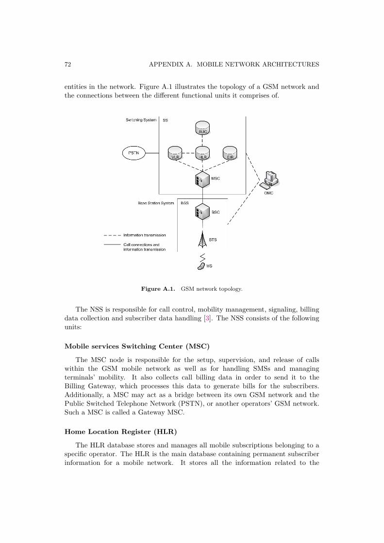
72 APPENDIX A. MOBILE NETWORK ARCHITECTURES
entities in the network. Figure A.1 illustrates the topology of a GSM network andthe connections between the different functional units it comprises of.
Figure A.1. GSM network topology.
The NSS is responsible for call control, mobility management, signaling, billingdata collection and subscriber data handling [3]. The NSS consists of the followingunits:
Mobile services Switching Center (MSC)
The MSC node is responsible for the setup, supervision, and release of callswithin the GSM mobile network as well as for handling SMSs and managingterminals’ mobility. It also collects call billing data in order to send it to theBilling Gateway, which processes this data to generate bills for the subscribers.Additionally, a MSC may act as a bridge between its own GSM network and thePublic Switched Telephone Network (PSTN), or another operators’ GSM network.Such a MSC is called a Gateway MSC.
Home Location Register (HLR)
The HLR database stores and manages all mobile subscriptions belonging to aspecific operator. The HLR is the main database containing permanent subscriberinformation for a mobile network. It stores all the information related to the
A.1. MOBILE NETWORK ARCHITECTURE 73
subscriber: the International Mobile Subscriber Identity (IMSI), the Mobile StationIntegrated Services Digital Network (MSISDN), which is the subscriber’s phonenumber, information about the subscriber’s supplementary services, authenticationdata, and location information.
Visitor Location Register (VLR)
The Visitor Location Register (VLR) is another database in a mobile commu-nication network associated with a specific MSC. It contains information about allmobile terminals currently located in this MSC’s service area. The VLR maintainsthe temporary subscriber information needed by the MSC to provide service (e.g.route a call to the correct base station) to visiting subscribers. The information inthe VLR changes dynamically, as the subscribers move from cell to cell and networkto network. In order to obtain service a mobile terminal registers with the networkand this information enables the MSC to determine if it can be authenticated andif it is authorized for each specific service - and it also enables calls to and from thismobile terminal to be effectively handled and routed. The VLR can be seen as adistributed subset of the HLR as, when a mobile station roams into a new MSC’sservice area, the VLR connected to this MSC requests data about the mobile stationfrom the HLR and stores the response in the local VLR. If the mobile station makesor receives another call without changing its service area, then the VLR will usethe subscriber’s information that it already has for authentication and call set-up.The database entry of the subscriber may be deleted once the subscriber leaves theMSC service area (note that the deletion may or may not occur quickly dependingupon the probability that the subscriber may return to this service area).
Authentication Center (AUC)
The Authentication Center (AUC) is a database that is connected to the HLR.This database provides the HLR with the subscriber’s authentication and encryptionparameters that are used to verify the subscriber’s identity and to ensure theconfidentiality of each call. The AUC protects network operators from fraud andis used to authenticate each Subscriber Identity Module card (SIM card) whena terminal with this SIM card attempts to connect to the network (typicallywhen the phone is powered on in the network operator’s service area). Once theauthentication is successful, an encryption key is generated, and this key is used inall communications between the mobile terminal and the network.
Equipment Identity Register (EIR)
The Equipment Identity Register (EIR) is an optional database that containsmobile equipment identity information which helps to block calls from stolen,unauthorized, or defective mobile stations. Operators can maintain three differentlists of International Mobile Equipment Identities (IMEI) in their EIR: a white listcontaining valid mobile terminals, a grey list where dubious mobile equipment is
74 APPENDIX A. MOBILE NETWORK ARCHITECTURES
included, and a black list containing the mobile devices to which the service is tobe denied.
The Base Station Subsystem (BSS) is responsible for all radio-related features.Typically, a MSC controls several BSSs, covering a large geographical area that isdivided into many cells [3]. This subsystem is composed of: Base Station Controller(BSC) and Base Transceiver Station (BTS).
Base Station Controller (BSC)
The Base Station Controller (BSC) provides all the radio-related functions andphysical links between the MSC and the Base Transceiver Station (BTS). It alsoimplements functions such as handover, cell configuration data, channel assignment,and control of radio frequency and power levels in each connected BTS.
Base Transceiver Station (BTS)
The Base Transceiver Station (BTS) handles the radio interface to the mobilestation. It facilitates the communication between the mobile devices and thenetwork. The BTS is the radio equipment (transceivers and antennas) needed toserve each cell in the network. Normally, a group of BTSs are controlled by a BSC.
Finally, the Network Management Subsystem (NMS) is the entity via which thenetwork operator monitors and controls the whole system. The Operation SupportSystem (OSS) can be divided into a two-level management function formed by aNetwork Management Center (NMC) responsible for the centralized control of thesystem, and subordinate Operation and Maintenance Centers (OMCs) focused onregional maintenance issues. The functions of the NMS can be divided into threegroups [3]:
Fault management to ensure the correct operation of the network and a rapidrecovery when failures occur.
Configuration management to maintain updated information about operationand configuration of the network elements.
Performance management The NMS collects data from the network elements sothat the actual performance of the network can be compared to the expectedperformance.
A.1.2. Universal Mobile Telecommunications System (UMTS)UMTS is a third generation (3G) mobile cellular technology standard developed
by the Third Generation Partnership Project (3GPP) [2]. This standard defines a
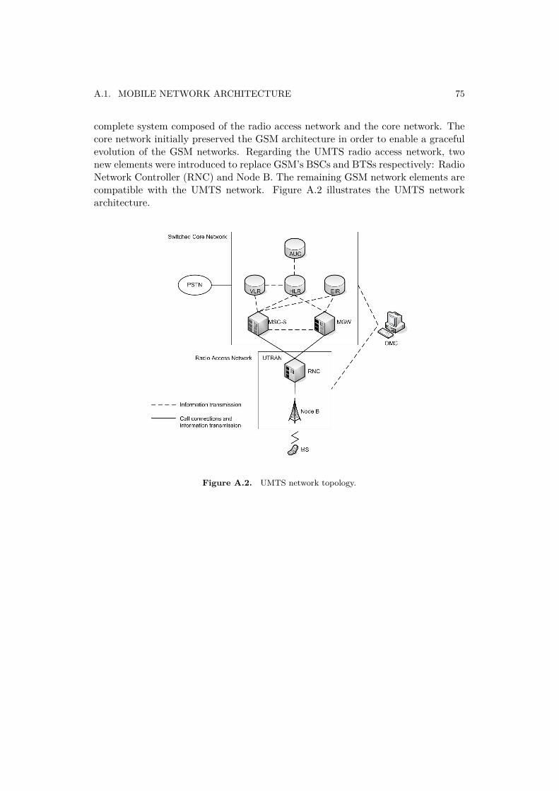
A.1. MOBILE NETWORK ARCHITECTURE 75
complete system composed of the radio access network and the core network. Thecore network initially preserved the GSM architecture in order to enable a gracefulevolution of the GSM networks. Regarding the UMTS radio access network, twonew elements were introduced to replace GSM’s BSCs and BTSs respectively: RadioNetwork Controller (RNC) and Node B. The remaining GSM network elements arecompatible with the UMTS network. Figure A.2 illustrates the UMTS networkarchitecture.
Figure A.2. UMTS network topology.


