Embed Size (px)
Citation preview
COMPANY
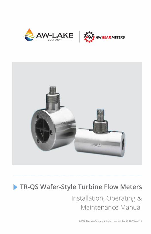
Installation, Operating & Maintenance Manual
TR-QS Wafer-Style Turbine Flow Meters
©2016 AW-Lake Company. All rights reserved. Doc ID:TRQSMAN16
2
Table of Contents
ContentsTable of Contents .......................................................................................... 2Introduction ................................................................................................. 3Operating Principle ....................................................................................... 3Technical Specifications ................................................................................ 4Materials of Construction ............................................................................. 4Measuring Accuracy ........................................................................................... 4Repeatability ...................................................................................................... 4Flow Measuring Range ....................................................................................... 4Maximum Operating Pressure ............................................................................ 4Maximum Operating Temperature ..................................................................... 4End Connections ................................................................................................. 4Installation ................................................................................................... 5Installation Kits ............................................................................................ 6Each kit includes studs, nuts, gaskets and spacer rings. ..................................... 6Operational Startup ...................................................................................... 7Trouble ............................................................................................................... 8Possible Cause .................................................................................................... 8Remedy .............................................................................................................. 8Trouble ............................................................................................................... 9Possible Cause .................................................................................................... 9Remedy .............................................................................................................. 9Troubleshooting Guide ................................................................................. 8Troubleshooting Guide ................................................................................. 9

3
IntroductionThe Explosion-Proof Wafer-Style turbine flow meter was developed for liquid applications where accuracy and dependability are of concern to the operator. The stainless steel body incorporates a helical turbine with tungsten carbide shaft and bearings. It provides an efficient, long service life and a cost-effective solution for your measurement requirements.
Simple in design and construction, this meter uses modified upstream and downstream flow straighteners for a high degree of flow accuracy. Its between-the-flange design eliminates the need for mating flanges, requiring less space in the flow line, lowering costs and providing easy, one-man installation.
The meter produces a sine wave signal proportional to its volumetric flow rate. With optional electronics, this turbine meter provides local flow rate and volume totalization and will interface with most instruments, PLCs and computers.
Operating PrincipleFluid entering the meter passes through the inlet flow straightener which reduces its turbulent flow pattern and improves the fluid’s velocity profile. Fluid then passes through the turbine, causing it to rotate at a speed proportional to the fluidvelocity. As each turbine blade passes through the magnetic field, the blade generates an AC voltage pulse in the pickup coil at the base of the magnetic pickup (see Figure 1). These pulses produce an output frequency proportional to the volumetric flow through the meter. The output frequency represents flow rate and/or totalization of fluid passing through the turbine flow meter.
Figure 1. Schematic illustration of electric signal generated by rotor movement
4
Materials of ConstructionBody & Rotor Support 316 Stainless Steel
Bearings Tungsten Carbide
Rotor Stainless Steel
Rotor Shaft Tungsten Carbide
Maximum Operating PressureRefer to ASME/ANSI B16.5-1996
Maximum Operating TemperatureFluid temperature of -150° to 300°F
End ConnectionsWafer-style ASME/ANSI B16.5-1996• Threaded, Flange, Graloc & Victaulic
Measuring Accuracy± 1.0% of reading or better
Repeatability± 0.1%
Flow Measuring Range.05 to 5,000 GPM (gal/min) (per flange rating of install kit)
Technical Specifications
*Actual pressure rating depends on installtion connection.
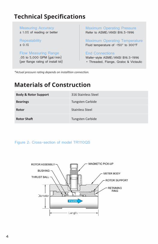
Figure 2: Cross-section of model TR1110QS
5
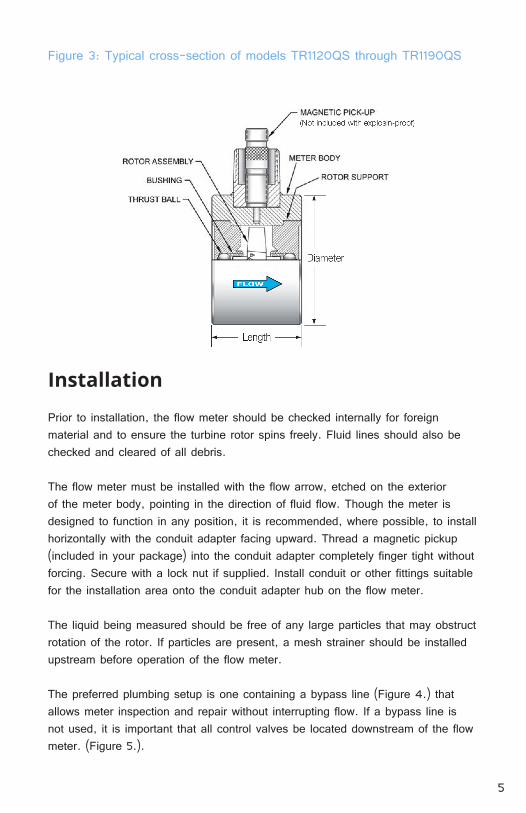
Figure 3: Typical cross-section of models TR1120QS through TR1190QS
Installation
Prior to installation, the flow meter should be checked internally for foreign material and to ensure the turbine rotor spins freely. Fluid lines should also be checked and cleared of all debris.
The flow meter must be installed with the flow arrow, etched on the exterior of the meter body, pointing in the direction of fluid flow. Though the meter is designed to function in any position, it is recommended, where possible, to install horizontally with the conduit adapter facing upward. Thread a magnetic pickup (included in your package) into the conduit adapter completely finger tight without forcing. Secure with a lock nut if supplied. Install conduit or other fittings suitable for the installation area onto the conduit adapter hub on the flow meter.
The liquid being measured should be free of any large particles that may obstruct rotation of the rotor. If particles are present, a mesh strainer should be installed upstream before operation of the flow meter.
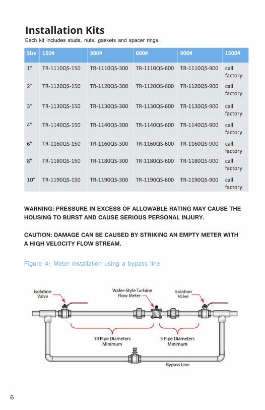
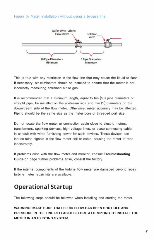
The preferred plumbing setup is one containing a bypass line (Figure 4.) that allows meter inspection and repair without interrupting flow. If a bypass line is not used, it is important that all control valves be located downstream of the flow meter. (Figure 5.).
6
Installation Kits
Size 150# 300# 600# 900# 1500#
1” TR-1110QS-150 TR-1110QS-300 TR-1110QS-600 TR-1110QS-900 call factory
2” TR-1120QS-150 TR-1120QS-300 TR-1120QS-600 TR-1120QS-900 call factory
3” TR-1130QS-150 TR-1130QS-300 TR-1130QS-600 TR-1130QS-900 call factory
4” TR-1140QS-150 TR-1140QS-300 TR-1140QS-600 TR-1140QS-900 call factory
6” TR-1160QS-150 TR-1160QS-300 TR-1160QS-600 TR-1160QS-900 call factory
8” TR-1180QS-150 TR-1180QS-300 TR-1180QS-600 TR-1180QS-900 call factory
10” TR-1190QS-150 TR-1190QS-300 TR-1190QS-600 TR-1190QS-900 call factory
Each kit includes studs, nuts, gaskets and spacer rings.
WARNING: PRESSURE IN EXCESS OF ALLOWABLE RATING MAY CAUSE THE HOUSING TO BURST AND CAUSE SERIOUS PERSONAL INJURY.
CAUTION: DAMAGE CAN BE CAUSED BY STRIKING AN EMPTY METER WITH A HIGH VELOCITY FLOW STREAM.
Figure 4: Meter installation using a bypass line
7
Each kit includes studs, nuts, gaskets and spacer rings.
Figure 5: Meter installation without using a bypass line
This is true with any restriction in the flow line that may cause the liquid to flash. If necessary, air eliminators should be installed to ensure that the meter is not incorrectly measuring entrained air or gas.
It is recommended that a minimum length, equal to ten (10) pipe diameters of straight pipe, be installed on the upstream side and five (5) diameters on the downstream side of the flow meter. Otherwise, meter accuracy may be affected. Piping should be the same size as the meter bore or threaded port size.
Do not locate the flow meter or connection cable close to electric motors, transformers, sparking devices, high voltage lines, or place connecting cable in conduit with wires furnishing power for such devices. These devices can induce false signals in the flow meter coil or cable, causing the meter to read inaccurately.
If problems arise with the flow meter and monitor, consult Troubleshooting Guide on page further problems arise, consult the factory.
If the internal components of the turbine flow meter are damaged beyond repair, turbine meter repair kits are available.
Operational Startup
The following steps should be followed when installing and starting the meter.
WARNING: MAKE SURE THAT FLUID FLOW HAS BEEN SHUT OFF AND PRESSURE IN THE LINE RELEASED BEFORE ATTEMPTING TO INSTALL THE METER IN AN EXISTING SYSTEM.
8
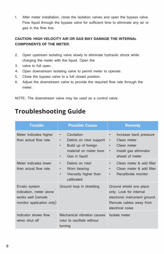
1. After meter installation, close the isolation valves and open the bypass valve. Flow liquid through the bypass valve for sufficient time to eliminate any air or gas in the flow line.
CAUTION: HIGH VELOCITY AIR OR GAS MAY DAMAGE THE INTERNAL COMPONENTS OF THE METER.
2. Open upstream isolating valve slowly to eliminate hydraulic shock while charging the meter with the liquid. Open the
3. valve to full open.4. Open downstream isolating valve to permit meter to operate.5. Close the bypass valve to a full closed position.6. Adjust the downstream valve to provide the required flow rate through the
meter.
NOTE: The downstream valve may be used as a control valve.
Troubleshooting Guide
Trouble Possible Cause Remedy
Meter indicates higher than actual flow rate
• Cavitation• Debris on rotor support• Build up of foreign
material on meter bore• Gas in liquid
• Increase back pressure• Clean meter• Clean meter• Install gas eliminator
ahead of meter
Meter indicates lower than actual flow rate
• Debris on rotor• Worn bearing• Viscosity higher than
calibrated
• Clean meter & add filter• Clean meter & add filter• Recalibrate monitor
Erratic system indication, meter alone works well (remote monitor application only)
Ground loop in shielding Ground shield one place only. Look for internal electronic instrument ground. Reroute cables away from electrical noise
Indicator shows flow when shut off
Mechanical vibration causes rotor to oscillate without turning
Isolate meter
9
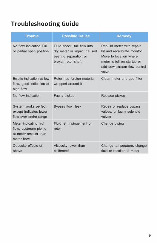
Trouble Possible Cause Remedy
No flow indication Full or partial open position
Fluid shock, full flow into dry meter or impact caused bearing separation or broken rotor shaft
Rebuild meter with repair kit and recalibrate monitor. Move to location where meter is full on startup or add downstream flow control valve
Erratic indication at low flow, good indication at high flow
Rotor has foreign material wrapped around it
Clean meter and add filter
No flow indication Faulty pickup Replace pickup
System works perfect, except indicates lower flow over entire range
Bypass flow, leak Repair or replace bypass valves, or faulty solenoidvalves
Meter indicating high flow, upstream piping at meter smaller than meter bore
Fluid jet impingement on rotor
Change piping
Opposite effects of above
Viscosity lower than calibrated
Change temperature, change fluid or recalibrate meter
Troubleshooting Guide

10

11

262.884.9800 | www.aw-lake.com2440 W. Corporate Preserve Dr. #600 Oak Creek, WI 53154
COMPANY
©2016 AW-Lake Company. All rights reserved. Doc ID:TRQSMAN16