Embed Size (px)
Citation preview
ETSI TR 103 288 V1.1.1 (2016-02)
Electromagnetic compatibility and Radio spectrum Matters (ERM);
Report of the CENELEC/ETSI Joint Working Group in response to the EC letter
ENTRP/F5/DP/MM/entr.f5.(2013)43164 to the ESOs
�
TECHNICAL REPORT
ETSI
ETSI TR 103 288 V1.1.1 (2016-02) 2
Reference DTR/ERM-JWGCLC-0001
Keywords EMC, radio
CEN CENELEC ETSI
Avenue Marnix 17 Avenue Marnix 17 650 Route des Lucioles B-1000 Brussels - BELGIUM B-1000 Brussels - BELGIUM F-06921 Sophia Antipolis Cedex - FRANCE Tel: + 32 2 550 08 11 Tel.: +32 2 519 68 71 Tel.: +33 4 92 94 42 00 Fax: + 32 2 550 08 19 Fax: +32 2 519 69 19 Fax: +33 4 93 65 47 16 Siret N° 348 623 562 00017 - NAF 742 C Association à but non lucratif enregistrée à la Sous-Préfecture de Grasse (06) N° 7803/88
Important notice
The present document can be downloaded from: http://www.etsi.org/standards-search
The present document may be made available in electronic versions and/or in print. The content of any electronic and/or print versions of the present document shall not be modified without the prior written authorization of ETSI. In case of any
existing or perceived difference in contents between such versions and/or in print, the only prevailing document is the print of the Portable Document Format (PDF) version kept on a specific network drive within ETSI Secretariat.
Users of the present document should be aware that the document may be subject to revision or change of status. Information on the current status of this and other ETSI documents is available at
http://portal.etsi.org/tb/status/status.asp
If you find errors in the present document, please send your comment to one of the following services: https://portal.etsi.org/People/CommiteeSupportStaff.aspx
Copyright Notification
No part may be reproduced or utilized in any form or by any means, electronic or mechanical, including photocopying and microfilm except as authorized by written permission of ETSI.
The content of the PDF version shall not be modified without the written authorization of ETSI. The copyright and the foregoing restriction extend to reproduction in all media.
© European Telecommunications Standards Institute 2016.
© Comité Européen de Normalisation Electrotechnique 2016. All rights reserved.
DECTTM, PLUGTESTSTM, UMTSTM and the ETSI logo are Trade Marks of ETSI registered for the benefit of its Members.
3GPPTM and LTE™ are Trade Marks of ETSI registered for the benefit of its Members and of the 3GPP Organizational Partners.
GSM® and the GSM logo are Trade Marks registered and owned by the GSM Association.
ETSI
ETSI TR 103 288 V1.1.1 (2016-02) 3
Contents Intellectual Property Rights ................................................................................................................................ 6
Foreword ............................................................................................................................................................. 6
Modal verbs terminology .................................................................................................................................... 7
Executive summary ............................................................................................................................................ 7
Introduction ........................................................................................................................................................ 7
1 Scope ........................................................................................................................................................ 9
2 References ................................................................................................................................................ 9
2.1 Normative references ......................................................................................................................................... 9
2.2 Informative references ........................................................................................................................................ 9
3 Definitions, symbols and abbreviations ................................................................................................. 13
3.1 Definitions ........................................................................................................................................................ 13
3.2 Symbols ............................................................................................................................................................ 13
3.3 Abbreviations ................................................................................................................................................... 13
4 Descriptions of the new systems operating in the 800 MHz band and expected in the 700 MHz band ........................................................................................................................................................ 15
4.1 LTE Idle Mode ................................................................................................................................................. 15
4.2 Spectrum emission mask .................................................................................................................................. 15
5 Descriptions of the interference mechanisms for the existing services operating in the 800 MHz band and those expected in the 700 MHz band ...................................................................................... 15
5.1 Digital Terrestrial Television Broadcasting ..................................................................................................... 15
5.1.1 Radio issues ................................................................................................................................................ 15
5.1.2 EMC issues ................................................................................................................................................. 16
5.1.2.1 RF cabling ............................................................................................................................................. 16
5.1.2.2 Components for private and communal aerial systems antennas .......................................................... 16
5.1.2.3 Aerial amplifiers and splitter amplifiers ................................................................................................ 16
5.2 Impact from the Mobile Broadband Service (LTE) on the SRD in the frequency band 863 MHz - 876 MHz (Short Range Devices) ..................................................................................................................... 17
5.2.1 Definition of a Short range Device (SRD) .................................................................................................. 17
5.2.2 Spectrum use within 800 MHz ................................................................................................................... 17
5.2.3 LTE and SRDs Co-existence analysis ........................................................................................................ 18
5.2.3.1 ECC Report 207 .................................................................................................................................... 18
5.2.3.2 Additional simulation analysis from ETSI ERM/MSG TFES .............................................................. 18
5.2.4 Experience of the LTE800 network deployment in France ........................................................................ 18
5.2.5 RFID ........................................................................................................................................................... 19
5.2.6 Improvements for SRDs ............................................................................................................................. 19
5.2.7 Improvements for LTE UE ......................................................................................................................... 19
5.3 Private/Professional Mobile Radio (PMR) ....................................................................................................... 20
5.3.1 Wireless broadband relevant to PMR systems ............................................................................................ 20
5.3.2 Potential future use of the 700 MHz for PPDR........................................................................................... 20
5.3.3 PMSE .......................................................................................................................................................... 21
5.3.3.1 PMSE Definition ................................................................................................................................... 21
5.3.3.2 Spectrum Use ........................................................................................................................................ 21
5.3.4 Assistive Listening Devices (ALDs)........................................................................................................... 21
6 Relevant harmonised standards .............................................................................................................. 21
6.1 List of standards ............................................................................................................................................... 21
6.2 Further information on the update of standards ................................................................................................ 22
6.2.1 Update of ETSI EN 301 908-13.................................................................................................................. 22
6.2.2 Definition of Spectrum Emission Mask requirements in ETSI TS 136 101 and ETSI EN 301 908-13 ..... 22
6.2.3 RFID standard ETSI EN 302 208 ............................................................................................................... 23
6.2.4 Update of PMSE standards ......................................................................................................................... 23
6.2.5 Update of PMR standards ........................................................................................................................... 23
6.3 Need for a new harmonised radio standard ...................................................................................................... 24

ETSI
ETSI TR 103 288 V1.1.1 (2016-02) 4
7 Remaining issues .................................................................................................................................... 24
7.1 Classification system for ready-made cable/connectors ................................................................................... 24
7.2 Performance characteristics of TV connectors ................................................................................................. 24
7.3 Further RFID analysis ...................................................................................................................................... 24
7.4 Further work on twisted pair wired systems ..................................................................................................... 24
8 Conclusion .............................................................................................................................................. 24
Annex A: Letter from the Commission ................................................................................................ 26
Annex B: LTE signal ............................................................................................................................. 29
B.1 LTE signal structure ............................................................................................................................... 29
B.2 BS idle signals ........................................................................................................................................ 30
B.3 E-TM2 and E-TM2/"LTE_BS-idle_V2" comparison ............................................................................ 31
Annex C: LTE band 20 devices and SRD coexistence ........................................................................ 35
C.1 LTE Out of Band Emissions Specifications ........................................................................................... 35
C.2 SRD Rx performance specifications ...................................................................................................... 36
Annex D: Experience of LTE800 networks deployment in France ................................................... 38
Annex E: Technical details and proposals: LTE & TV co-existence ................................................ 39
Annex F: Impact from the Mobile Broadband Service (LTE) on the SRD in the frequency band 863 MHz - 876 MHz (Short Range Devices) - TRP modelling and simulation results ..................................................................................................................................... 42
F.1 LTE and SRDs Co-existence analysis in ECC Report 207 .................................................................... 42
F.2 Review of Simulation analysis in ECC Report 207 ............................................................................... 43
F.2.1 Assumptions on the SRD wanted signal distribution (dRSS) ........................................................................... 43
F.2.2 Number of LTE (interfering) UEs in 10 MHz .................................................................................................. 43
F.2.3 Activity Factor of the LTE (interfering) UEs ................................................................................................... 44
F.3 Additional Simulation Analysis for the Co-existence of LTE and SRDs within the 800 MHz band .... 45
F.3.1 Simulation Assumptions & Methodology ........................................................................................................ 45
F.3.2 Simulation Results ............................................................................................................................................ 46
F.3.2.1 Results for SRD Rx Cat.2 Metering ........................................................................................................... 46
F.3.2.2 Results for SRD Cat. 2 Audio ..................................................................................................................... 47
F.4 Conclusions & Summary on the impact from LTE on SRD from the additional simulation ................. 48
F.4.1 Summary of Observations on Simulation Assumptions and Methodology ...................................................... 48
F.5 Simulation modelling of LTE UE's TX power distribution in 832 - 862 MHz adjacent to SRDs (863 - 870 MHz) ..................................................................................................................................... 48
F.5.1 TRP Measurement ............................................................................................................................................ 48
F.5.2 TRP Distribution Analysis ............................................................................................................................... 49
F.5.3 Proposed TRP Distribution .............................................................................................................................. 49
F.5.4 Conclusions & Summary on the simulation modelling of LTE UE's TX power distribution in 832 - 862 MHz adjacent to SRDs (863 - 870 MHz) ......................................................................................... 50
F.6 Results based on TRP modelling and an improvement of the LTE UE spectrum emission mask by 3 dB ........................................................................................................................................................ 51
F.7 Proposal .................................................................................................................................................. 53
Annex G: Effect of interference to RFID by OOB emissions from LTE UE .................................... 54
G.1 Environment for 863 - 870 MHz Short Range Devices ......................................................................... 54
G.2 Investigation into the effects of LTE UE on RFID ................................................................................ 54
Annex H: Wireless broadband relevant to PMR systems ................................................................... 57
ETSI
ETSI TR 103 288 V1.1.1 (2016-02) 5
H.1 Description of LTE Signals .................................................................................................................... 57
H.2 PMR Immunity Measurements .............................................................................................................. 64
H.2.1 Definition of immunity test signals .................................................................................................................. 64
H.2.2 Categorization of Radio Frequency immunity of current equipment ............................................................... 64
H.2.2.1 Test Method ................................................................................................................................................ 64
H.2.2.2 Results of the measurements ....................................................................................................................... 64
H.2.2.3 Implications of the measurements .............................................................................................................. 66
Annex I: Detailed information on PMSE and ALDs ......................................................................... 67
Annex J: Change History ..................................................................................................................... 69
History .............................................................................................................................................................. 70
ETSI
ETSI TR 103 288 V1.1.1 (2016-02) 6
Intellectual Property Rights IPRs essential or potentially essential to the present document may have been declared to ETSI. The information pertaining to these essential IPRs, if any, is publicly available for ETSI members and non-members, and can be found in ETSI SR 000 314: "Intellectual Property Rights (IPRs); Essential, or potentially Essential, IPRs notified to ETSI in respect of ETSI standards", which is available from the ETSI Secretariat. Latest updates are available on the ETSI Web server (https://ipr.etsi.org).
Pursuant to the ETSI IPR Policy, no investigation, including IPR searches, has been carried out by ETSI. No guarantee can be given as to the existence of other IPRs not referenced in ETSI SR 000 314 (or the updates on the ETSI Web server) which are, or may be, or may become, essential to the present document.
Foreword This Technical Report (TR) has been produced by ETSI Technical Committee Electromagnetic compatibility and Radio spectrum Matters (ERM).
The present document has been produced by the CENELEC- ETSI Joint Working Group (JWG) in response to the letter from the European Commission dated the 13th February 2013 (see annex A). The letter requested CENELEC and ETSI to undertake the following standardisation activities:
a) Revise or develop harmonised standards conferring presumption of conformity with the EMC Directive and/or R&TTE Directive [i.26], and/or European standards covering the following aspects:
1) Improved immunity of all broadcast receivers operating in the whole frequency bands 174 - 230 MHz and 470 - 862 MHz including in particular digital terrestrial TV and satellite TV receivers. This implies a new revision of CENELEC EN 55020 [i.2] including reconsideration of the scope of the so-called "exclusion band" in the context of new uses of spectrum, and should cover in particular immunity against signals with discontinuous transmission such as the «idle mode»5 of LTE equipment operating in the 800 MHz band (see below under b)). A European modification of the future CENELEC EN 55035 [i.36]
improving immunity at enclosure and antenna ports is also to be considered.
Selectivity of TV receivers has been covered by existing test suites already developed in Europe (e.g. DTG D-Book 7, Nordig, E-book), and these could be used as the basis for improved antenna port immunity requirements in both CENELEC EN 55020 [i.2] and the future CENELEC EN 55035 [i.36].
2) Improved immunity and related specifications of other equipment relevant in the reception of digital terrestrial TV services, i.e. amplifiers, passive equipment and filters, especially the immunity of equipment operating below 790 MHz to LTE signals in the 800 MHz band.
3) To investigate improved robustness of SRD and suitable mitigation techniques in order to enhance the sharing environment between LTE and short-range devices operating in the 800 MHz and adjacent bands.
b) Revise or develop harmonised standards conferring presumption of conformity with the R&TTE Directive [i.26] and/or European standards covering the following aspects:
- Improved characterization, revision of requirements and appropriate reduction of out of band emissions of LTE equipment. In particular, a comprehensive definition of the idle mode emissions mentioned in item a) above 1 is required.
These standardisation activities should take place, where appropriate, under available standardisation mandates issued in support of the EMC Directive [i.43] and R&TTE Directive [i.26]. In all cases, close co-operation with ECC is to be considered as essential.
Such standardisation efforts are critical for a timely and comprehensive exploitation of the potential of wireless broadband in the 800 MHz band for citizens, business and public services. Taking into account that novel standards proposed to manufacturers generally need at least 18 months before they can reach the market it is urgent that the relevant standards are updated as soon as possible.
ETSI
ETSI TR 103 288 V1.1.1 (2016-02) 7
Modal verbs terminology In the present document "shall", "shall not", "should", "should not", "may", "need not", "will", "will not", "can" and "cannot" are to be interpreted as described in clause 3.2 of the ETSI Drafting Rules (Verbal forms for the expression of provisions).
"must" and "must not" are NOT allowed in ETSI deliverables except when used in direct citation.
Executive summary The present document is developed jointly by CENELEC and ETSI in response to the EC letter ENTRP/F5/DP/MM/entr.f5.(2013)43164 to the ESOs. The text of the letter is given in annex A of the present document.
The interference situation between the mobile service and the existing services in the 800 MHz band was considered and is addressed in the present document.
NOTE: More detailed information on the interference assessment is provided in several annexes of the present document.
Initial assumptions were made for the future situation in the 700 MHz band, even though the new services in this band are not standardised yet.
Some issues for further investigation and also a need for a new standard for terrestrial TV mast head amplifiers were identified.
The resulting activities, which were also asked by the EC letter, are:
• ETSI EN 301 908-13 [i.14] will be updated with a SEM reduction of 3 dB.
• ETSI EN 300 220 [i.35] will be updated deleting the Cat 3 for the 863 - 870 MHz band. Cat. 2 will therefore become the minimum performance and investigation on the possible introduction of a new Category 1,5 are ongoing.
• New Harmonised Standards will be created for satellite and terrestrial broadcasting TV receivers.
• Cable networks were addressed under the work of JWG DD [i.1].
Introduction The present document has been produced jointly between CENELEC and ETSI addressing the objectives as given in the scope.
The present document presents in clause 4 a description of the new systems operating in the 800 MHz band and those expected in the 700 MHz band.
Clause 5 is a description of interference mechanisms for the different services operating in the 800 MHz band and those expected in the 700 MHz covering in its subclauses the mobile, digital terrestrial television broadcasting, as well as the impact on short range devices in the band 863 - 876 MHz band and the private/professional mobile radio (PMR).
Clause 6 presents the relevant harmonised standards recognized needing to be updated and recommendations for development of any new standardisation work.
Clause 7 presents information on a list of issues identified that are not covered by the present document but are recommended to be addressed.
Clause 8 presents a conclusion with the key points arising from the present document with an Executive Summary included at the beginning of the present document produced as a summary also for the European Commission.
Detailed supporting information for each of the main clauses above are provided in corresponding annexes to the present document.
ETSI
ETSI TR 103 288 V1.1.1 (2016-02) 8
Background information on the JWG DD, that also worked on the 800 MHz band:
The updating of the relevant standards for cable network systems had already been fulfilled by the work of CENELEC TC 210 and TC 209 as was identified by the JWG on Digital Dividend (DD) [i.1].
With regards to Cable Systems JWG DD identified that LTE800 (790 - 862 MHz) disturbed consumer services where LTE800 is operated in coexisting and adjacent channels. ETSI or CENELEC has not itself verified level of disturbance to consumer services caused by LTE800 however this has been demonstrated by third party laboratory testing and some field testing. Furthermore the details are documented from the reports produced during the JWG DD. Recommendations arising from the output of JWG DD resulted in changes to the relevant standards with the assessment completed and the harmonised standards CENELEC EN 55020 [i.2] and CENELEC EN 50083-2 [i.3] adapted to the new requirements. There is no requirement for any further standardisation work. Any changes in existing radio environment from new mobile use cases would need further investigation.
The experiences from the studies given below in the present document on the 800 MHz band may support the potential implications to the 700 MHz, for example:
• The EC decision [i.4] on 800 MHz had an impact on cable networks, however this is manageable for existing equipment for examples as in Austria and Netherlands where the Authorities encouraged the mobile LTE operators to manage the disturbance to cable consumer services in cooperation with the Cable Operators. Furthermore in Austria the criteria used is the relevant CENELEC Standards for Cable.
• In the first draft JWG report [i.1], the Mobile Operator stated that the very high transmit power described in the CEPT report 30 [i.5] is not usable in many networks. Due to planning reasons and coexistence with the adjacent signals from the other mobile operators the output transmission power has to be reduced which are operational requirements.
• The recommendations [i.6] for updating CENELEC standards resulted in new values within CENELEC EN 55020 Amendment 11 [i.2] and the new version of the CENELEC EN 50083-2 [i.3]. In the work of this standardisation projects all relevant stakeholders were involved and accepted the new requirements.
• Due to the fact that the band plan for 700 MHz is not agreed yet and the services in this band are not known or standardised yet it is hard to assess the impact on cable networks. Without a clear assessment on the different technologies no predictions can be made at this point of time.
• The changes done to CENELEC EN 55020 [i.2] and the CENELEC EN 50083-2 [i.3] may also be sufficient to have the cable services coexisting with new services in the 700 MHz band if the technical decisions for mobile services in 700 MHz band are such that they aim to maintain the same level of performance as today for mobile in 800 MHz band. This consideration is based on the improved propagation characteristics in frequencies below 790 MHz band such that a reduction in the BS and UE transmit power levels is feasible.
ETSI
ETSI TR 103 288 V1.1.1 (2016-02) 9
1 Scope The present document:
• investigates and documents anticipated and/or planned changes in frequency use in the band 470 MHz - 862 MHz including the relevant characteristics of the expected radio technologies to be deployed in these and neighbouring bands, in particular the 863 - 870 MHz band used by Short-Range Devices (SRD);
• develops a description of the emerging electromagnetic environment in the above bands and evaluate how these changes will affect the co-existence services, systems and equipment;
• makes recommendations to the CENELEC and ETSI committees to revise affected Harmonised Standards and other European Standards as necessary to improve to co-existence of relevant services and equipment.
The present document is developed jointly by CENELEC and ETSI in response to the EC letter ENTRP/F5/DP/MM/entr.f5.(2013)43164 to the ESOs. The text of the letter is given in annex A of the present document.
The letter of the European Commission mentions the band 174 - 230 MHz with regard to the broadcast receivers. This does not imply any intention to modify the 174 - 230 MHz band. The band does not fall under the scope of the present document.
2 References
2.1 Normative references References are either specific (identified by date of publication and/or edition number or version number) or non-specific. For specific references, only the cited version applies. For non-specific references, the latest version of the referenced document (including any amendments) applies.
Referenced documents which are not found to be publicly available in the expected location might be found at http://docbox.etsi.org/Reference.
NOTE: While any hyperlinks included in this clause were valid at the time of publication, ETSI cannot guarantee their long term validity.
The following referenced documents are necessary for the application of the present document.
Not applicable.
2.2 Informative references References are either specific (identified by date of publication and/or edition number or version number) or non-specific. For specific references, only the cited version applies. For non-specific references, the latest version of the referenced document (including any amendments) applies.
NOTE: While any hyperlinks included in this clause were valid at the time of publication, ETSI cannot guarantee their long term validity.
The following referenced documents are not necessary for the application of the present document but they assist the user with regard to a particular subject area.
[i.1] Report on CENELEC/ETSI Joint Working Group on the Digital Dividend.
NOTE: Available at http://ec.europa.eu/DocsRoom/documents/10530/attachments/1/translations/en/renditions/native.
[i.2] CENELEC EN 55020:2007/A.1:2011: "Sound and television broadcast receivers and associated equipment - Immunity characteristics - Limits and methods of measurement".
[i.3] CENELEC EN 50083-2: "Cable networks for television signals, sound signals and interactive services - Part 2: Electromagnetic compatibility for equipment".
ETSI
ETSI TR 103 288 V1.1.1 (2016-02) 10
[i.4] Commission Decision 2010/267/EU of 6 May 2010 on harmonised technical conditions of use in the 790-862 MHz frequency band for terrestrial systems capable of providing electronic communications services in the European Union.
[i.5] CEPT Report 30: "The identification of common and minimal (least restrictive) technical conditions for 790 - 862 MHz for the digital dividend in the European Union".
[i.6] CENELEC/ETSI Joint Working Group Digital Dividend, TC210/Sec0657/INF: "List of standards to be considered by their respective committees for revision to take into account changes in spectrum use resulting from the UHF Digital Dividend".
NOTE: Available at http://ec.europa.eu/DocsRoom/documents/10530/attachments/2/translations/en/renditions/native.
[i.7] DTG D-Book.
NOTE: Available at http://www.dtg.org.uk/publications/dbook.html.
[i.8] NorDig.
NOTE: Available at http://www.nordig.org/.
[i.9] CENELEC EN 62216: "Digital terrestrial television receivers for the DVB-T system".
[i.10] CEPT Report 53: "to develop harmonised technical conditions for the 694-790 MHz ('700 MHz') frequency band in the EU for the provision of wireless broadband and other uses in support of EU spectrum policy objectives".
[i.11] Commission implementing Decision 2013/752/EU of 11 December 2013 amending Decision 2006/771/EC on harmonisation of the radio spectrum for use by short-range devices and repealing Decision 2005/928/EC.
[i.12] ECC Recommendation 70-03: "Relating to the Use of Short Range Devices (SRD)".
[i.13] ECC Report 207: "Adjacent band co-existence of SRDs in the band 863-870 MHz with LTE usage below 862 MHz".
[i.14] ETSI EN 301 908-13 (V7.1.1) (12-2015): "IMT cellular networks; Harmonised Standard covering the essential requirements of article 3.2 of the Radio Equipment Directive 2014/53/EU; Part 13: Evolved Universal Terrestrial Radio Access (E-UTRA) User Equipment (UE)".
[i.15] ITU-R Report IMT. Beyond 2020 Traffic.
[i.16] ETSI EN 300 086-1: "Electromagnetic compatibility and Radio spectrum Matters (ERM); Land Mobile Service; Radio equipment with an internal or external RF connector intended primarily for analogue speech; Part 1: Technical characteristics and methods of measurement".
[i.17] ETSI EN 300 086-2: "Electromagnetic compatibility and Radio spectrum Matters (ERM); Land Mobile Service; Radio equipment with an internal or external RF connector intended primarily for analogue speech; Part 2: Harmonized EN covering the essential requirements of article 3.2 of the R&TTE Directive".
[i.18] ETSI EN 300 296-1: "Electromagnetic compatibility and Radio spectrum Matters (ERM); Land Mobile Service; Radio equipment using integral antennas intended primarily for analogue speech; Part 1: Technical characteristics and methods of measurement".
[i.19] ETSI EN 300 296-2: "Electromagnetic compatibility and Radio spectrum Matters (ERM); Land Mobile Service; Radio equipment using integral antennas intended primarily for analogue speech; Part 2: Harmonized EN covering the essential requirements of article 3.2 of the R&TTE Directive".
[i.20] ETSI EN 300 113: "Land Mobile Service; Radio equipment intended for the transmission of data (and/or speech) using constant or non-constant envelope modulation and having an antenna connector; Harmonised Standard covering the essential requirements of article 3.2 of the Directive 2014/53/EU".
ETSI
ETSI TR 103 288 V1.1.1 (2016-02) 11
[i.21] ETSI EN 302 561: "Electromagnetic compatibility and Radio spectrum Matters (ERM); Land Mobile Service; Radio equipment using constant or non-constant envelope modulation operating in a channel bandwidth of 25 kHz, 50 kHz, 100 kHz or 150 kHz; Harmonized EN covering the essential requirements of article 3.2 of the R&TTE Directive".
[i.22] ETSI EN 300 341: "Land Mobile Service; Radio equipment using an integral antenna transmitting signals to initiate a specific response in the receiver; Harmonised Standard covering the essential requirements of article 3.2 of the Directive 2014/53/EU".
[i.23] ETSI EN 300 390: "Land Mobile Service; Radio equipment intended for the transmission of data (and speech) and using an integral antenna; Harmonised Standard covering the essential requirements of article 3.2 of the Directive 2014/53/EU Harmonised Standard covering the essential requirements of article 3.2 of the Directive 2014/53/EU".
[i.24] ETSI EN 301 166: "ElectroMagnetic Compatibility and Radio spectrum Matters (ERM); Land mobile service; Technical characteristics and test conditions for radio equipment for analogue and/or digital communication (speech and/or data) and operating on narrowband channels and having an antenna connector".
[i.25] Directive 2014/53/EU of the European Parliament and of the Council of 16 April 2014 on the harmonisation of the laws of the Member States relating to the making available on the market of radio equipment and repealing Directive 1999/5/EC (Radio Equipment Directive, "RED").
[i.26] Directive 1999/5/EC of the European Parliament and of the Council of 9 March 1999 on radio equipment and telecommunications terminal equipment and the mutual recognition of their conformity ("R&TTE Directive").
[i.27] ECC Report 199: "User requirements and spectrum needs for future European broadband PPDR systems (Wide Area Networks)".
[i.28] ETSI TS 136 101: "LTE; Evolved Universal Terrestrial Radio Access (E-UTRA); User Equipment (UE) radio transmission and reception (3GPP TS 36.101)".
[i.29] ETSI TS 136 521: "LTE; Evolved Universal Terrestrial Radio Access (E-UTRA); User Equipment (UE) conformance specification; Radio transmission and reception".
[i.30] ETSI EN 302 208: "Radio Frequency Identification Equipment operating in the band 865 MHz to 868 MHz with power levels up to 2 W and in the band 915 MHz to 921 MHz with power levels up to 4 W; Harmonized Standard covering the essential requirements of article 3.2 of the Directive 2014/53/EU".
[i.31] ECC Report 138: "DVB-T performance in the presence of UMTS".
[i.32] ECC Report 148: "DVB-T performance in the presence of LTE".
[i.33] Recommendation ITU-T G.9700: "Fast access to subscriber terminals (G.fast) - Power spectral density specification".
[i.34] Recommendation ITU-T G.9701: "Fast access to subscriber terminals (G.fast) - Physical layer specification".
[i.35] ETSI EN 300 220-1: "Short Range Devices (SRD) operating in the frequency range 25 MHz to 1 000 MHz; Part 1: Technical characteristics and test methods".
[i.36] CENELEC EN 55035: "Electromagnetic Compatibility of Multimedia equipment - Immunity Requirements".
[i.37] ETSI TR 102 546: "Electromagnetic compatibility and Radio spectrum Matters (ERM); Technical characteristics for Professional Wireless Microphone Systems (PWMS); System Reference Document".
[i.38] ETSI EN 300 422: "ElectroMagnetic Compatibility and Radio Spectrum Matters (ERM); Technical characteristics and test methods for wireless microphones in the 25 MHz to 3 GHz frequency range".
ETSI
ETSI TR 103 288 V1.1.1 (2016-02) 12
[i.39] ETSI EN 300 454: "ElectroMagnetic Compatibility and Radio Spectrum Matters (ERM); Wide band audio links".
[i.40] ETSI EN 300 357: "Integrated Services Digital Network (ISDN); Completion of Calls to Busy Subscriber (CCBS) supplementary service; Service description".
[i.41] ETSI TS 136 141: "LTE; Evolved Universal Terrestrial Radio Access (E-UTRA); Base Station (BS) conformance testing (3GPP TS 36.141)".
[i.42] ETSI TR 136 942: "LTE; Evolved Universal Terrestrial Radio Access (E-UTRA); Radio Frequency (RF) system scenarios (3GPP TR 36.942)".
[i.43] Directive 2004/108/EC of the European Parliament and of the Council of 15 December 2004 on the approximation of the laws of the Member States relating to electromagnetic compatibility and repealing Directive 89/336/EEC Text with EEA relevance (EMC Directive).
[i.44] ECC Report 204: "Spectrum use and future requirements for PMSE".
[i.45] CEPT Report 32: "Report from CEPT to the European Commission in response to the Mandate on "Technical considerations regarding harmonisation options for the digital dividend in the European Union - Recommendation on the best approach to ensure the continuation of existing Program Making and Special Events (PMSE) services operating in the UHF (470-862 MHz), including the assessment of the advantage of an EU-level approach".
[i.46] ECC Report 174: "Compatibility between the mobile service in the band 2500-2690 MHz and the radio determination service in the band 2700-2900 MHz".
[i.47] ETSI EN 301 357-1: "Electromagnetic compatibility and Radio spectrum Matters (ERM); Cordless audio devices in the range 25 MHz to 2 000 MHz; Part 1: Technical characteristics and test methods".
[i.48] ETSI TS 134 114: "Digital cellular telecommunications system (Phase 2+); Universal Mobile Telecommunications System (UMTS); LTE; User Equipment (UE) / Mobile Station (MS) Over The Air (OTA) antenna performance; Conformance testing (3GPP TS 34.114)".
[i.49] LTE 800 radio sites.
NOTE: Available at https://www.google.fr/url?sa=t&rct=j&q=&esrc=s&source=web&cd=1&cad=rja&uact=8&ved=0ahUKEwjjt_qjwO3KAhUDCBoKHfVVAoQQFggiMAA&url=http%3A%2F%2Fwww.anfr.fr%2Ffileadmin%2Fmediatheque%2Fdocuments%2Fsites%2FGuide_COMSIS_LTE_800_MHz__V2_1.pdf&usg=AFQjCNFoUvL7Y3h4nI5jnWVMjHEwoA19ZA&sig2=ladqAMTYHK6hukaY_MkX3w&bvm=bv.113943665,d.bGs.
[i.50] LTE 800 licences France.
NOTE: Available at http://www.arcep.fr/index.php?id=8571&tx_gsactualite_pi1%5buid%5d=1470&cHash=0a37c71df491974af4e0b66e1e389e92.
[i.51] ETSI EN 302 296: "Electromagnetic compatibility and Radio spectrum Matters (ERM); Transmitting equipment for the digital television broadcast service, Terrestrial (DVB-T); Part 2: Harmonized EN covering the essential requirements of article 3.2 of the R&TTE Directive".
[i.52] ETSI EN 303 340: "Digital Terrestrial TV Broadcast Receivers; Harmonised Standard covering the essential requirements of article 3.2 of the Directive 2014/53/EU".
[i.53] ETSI EN 303 345: "Radio Broadcast Receivers; Harmonised Standard covering the essential requirements of article 3.2 of the Directive 2014/53/EU".
[i.54] ETSI EN 303 354: "Amplifiers for broadcast reception in domestic premises; Harmonised Standard covering the essential requirements of article 3.2 of the Directive 2014/53/EU".
ETSI
ETSI TR 103 288 V1.1.1 (2016-02) 13
[i.55] Mobile-DTT(14)20: Meeting minutes of PTD-CG Mobile-DTT#4, 20 March 2014, Maisons-Alfort.
NOTE: Available at http://www.cept.org/ecc/groups/ecc/cpg/cpg-pt-d/client/meeting-documents?flid=2979.
[i.56] CPG-PTD(14)044_rev1: "Measurements for assessing the impact of OOBE as well as short pulse interferences from IMT user equipment to DTTB reception", CPG PTD#5, 13-17 January 2014, Rome.
NOTE: Available at http://www.cept.org/ecc/groups/ecc/cpg/cpg-pt-d/client/meeting-documents/file-history?fid=15116.
[i.57] EBU technical study: "How can mobile and broadcasting networks use adjacent bands?", ISSN: 1609-1469, 2011.
NOTE: Available at https://tech.ebu.ch/docs/techreview/trev_2011-Q1_digital-dividend_sami.pdf.
[i.58] Ofcom study: "80dB DTT ACS - is it possible, and at what cost?", November 2013.
NOTE: Available at http://stakeholders.ofcom.org.uk/binaries/spectrum/UHF700MHz/DTT_RX_study_stakeholder_presentation_20131125_released_20131122.pdf.
3 Definitions, symbols and abbreviations
3.1 Definitions For the purposes of the present document, the following terms and definitions apply:
LTE800: LTE system operating in the band from 790 MHz to 862 MHz
LTE700: LTE system operating in the band from 694 MHz to 790 MHz
3.2 Symbols For the purposes of the present document, the following symbols apply:
fc centre frequency
3.3 Abbreviations For the purposes of the present document, the following abbreviations apply:
3GPP Third Generation Partnership Project ACLR Adjacent Channel Leakage Ratio ACS Adjacent Channel Selectivity ALD Assistive Listening Device APC Adaptive Power Control BCH Bose-Chaudhuri-Hocquenghem (Code) BER Bit Error Rate BS Base Station CENELEC European Committee for Electrotechnical Standardisation CEPT European Conference of Post and Telecommunications CISPR Comité International Spécial des Perturbations Radioélectriques CP Cyclic Prefix CW Channel Width dB decibel dBm dB relative to 1 mW in 50 ohms DD Digital Dividend DD_UE Digital Dividend User Equipment DRSS Desired Received Signal Strength DTG Digital Tv Group
ETSI
ETSI TR 103 288 V1.1.1 (2016-02) 14
DTT Digital terrestrial Television DUT Device Under Test DVB-T Digital Video Broadcasting-Terrestrial EBU European Broadcasting Union EC European Commission ECC Electronic Communications Committee EMC Electromagnetic compatibility EN European Norm ERM Electromagnetic compatibility and Radio Matters E-TM E-UTRA Test Model ETSI European Telecommunication Standards Institute EVM Error Vector Magnitude FEC Forward Error Correction FS Free Space GHz GigaHertz HH Head Hand IEM In-Ear Monitoring ILK Interferer LinK ILR Interferer Link Receiver ILT Interferer Link Transmitter IMT International Mobile Telecommunications ITU-R International Telecommunications Union Radiocommunications sector JWG Joint Working Group LTE Long Term Evolution MCL Minimum Coupling Loss MHz MegaHertz NAS Non Access Stratum OOB Out of band OOBE Out Of Band Emissions OTA Over-The-Air PAPR Peak to Average Power Ratio PBCH Physical Broadcast CHannel PDSCH Physical Downlink Shared CHannel PMR Private/Professional Mobile Radio PMSE Program Making/Special Events PPDR Public Protection Disaster Relief PRB Physical Resource Block PSCH Primary Synchronisation CHannel PUCCH Physical Uplink Control CHannel QPSK Quadrature Phase Shift Keying RB Resource Block RBW Resolution BandWidth RE Resource Element RF Radio Frequency RFID Radio Frequency Identification rms root mean square RS Reference Signal SAW Surface Acoustic Wave SCH Synchronisation CHannel SDR Software-Defined Radio SEM Spectrum emission mask SINAD Signal to Noise And Distortion SRD Short Range Device SSCH Secondary Synchronisation CHannel TB Technical Body TC Technical Committee TFES Task Force for ERM and MSG for Harmonised Standards for IMT-2000 TPC Transmit Power Control TR Technical Report TRP Total Radiated Power TV TeleVision UE User Equipment
ETSI
ETSI TR 103 288 V1.1.1 (2016-02) 15
UHF Ultra-High Frequency UL Up Link UTRA Universal Terrestrial Radio Access VHF Very High Frequency VLR Victim Link Receiver WI Work Item
4 Descriptions of the new systems operating in the 800 MHz band and expected in the 700 MHz band
4.1 LTE Idle Mode The letter from the Commission (see annex A) was asking the definition for the idle mode emissions i.e. "Idle mode": traffic load levels tested: 0 % of LTE traffic.
ETSI ERM/MSG TFES proposed to use well defined existing test signal E-TM2, which would be close the requested "Idle mode" signal, for testing the immunity against LTE base station. However, in the tests carried out on TV receivers had indicated that the off-air recording of an 800 MHz LTE Base Station (BS) "LTE_BS-idle_V2" used in the D-book [i.7] provided a more severe test for TV receivers than E-TM2. Therefore ETSI ERM TG17 will start their work on harmonised standards for TV receivers using the LTE_BS-idle_V2 off-air recording as a test signal. JWG acknowledges this as an expedient short-term solution. In the longer term the JWG recommended that further investigations should be carried out to understand better the disturbance mechanism and to develop an appropriate test signal that could be specified and built in to laboratory test equipment. Co-operation on this has started between TV manufacturers and the LTE community within the ETSI MSG/TFES DD_UE group. More information on the LTE signal generally and E-TM2 and "LTE_BS-idle_V2" can be found in the clause B.3.
JWG acknowledges that UE has a different time-domain characteristic to a BS and recommends that ETSI ERM TG17 should also work with ETSI MSG/TFES DD_UE group to develop a test signal to enable the evaluation the immunity of Broadcasting receivers to UE operating in the 700 MHz band.
There are different understandings of different interests groups of the term "Idle Mode".
Further work is needed to develop a suitable test signal for immunity testing against BS and UE i.e. to define respective "time-varying signal with low load" signals. "Time-varying signal with low load" is expected to have the greatest disturbance potential. The definition should be done in ERM TG17 with the collaboration of TFES.
4.2 Spectrum emission mask For more information on SEM improvement see clause 5.2.7 of the present document.
5 Descriptions of the interference mechanisms for the existing services operating in the 800 MHz band and those expected in the 700 MHz band
5.1 Digital Terrestrial Television Broadcasting
5.1.1 Radio issues
LTE can cause interference due to overload and/or selectivity issues in some DTT reception situations (note this includes DVB-T/T2). Many of these cases identified antenna amplifiers as the weak link, showing the need for an appropriate harmonised radio standard for TV mast head amplifiers (see also clause 8 of the present document), but it is also necessary for the receiver to have adequate antenna port immunity performance in these areas - suitable parameters are contained in the UK's Digital Television Group (DTG) D-Book [i.7], NorDig [i.8] or CENELEC EN 62216 [i.9] specifications.
DTT receivers available on the market show different performances with respect to the overloading threshold and ACS performance characteristics criteria which impact directly their ability to cope with alternative technologies in adjacent
ETSI
ETSI TR 103 288 V1.1.1 (2016-02) 16
band. Also, some receivers show reduced performance in case of sources producing bursts of discontinuous interference, such as LTE transmissions.
To date, it has not been possible to finalize the new test signal requirements for the television receiver due to a lack of information about the special transmission modes of the LTE system. This is currently being studied in ETSI, and may result in a different signal to that currently used by the television industry. However for EMC tests LTE operation can be adequately simulated by an 80 % amplitude-modulated test, with the exception of the Idle Mode operation.
The experiences from the studies on 800 MHz band may support the potential implications to the 700 MHz.
CEPT Report 53 [i.10] for the EC mandate defines the technical conditions of using the 700 MHz band for the provision of electronic communication (mobile) services. Whilst the findings of the present document are supported, there is also a need to consider the use of realistic timescales to introduce such changes.
It should be noted that the channelling arrangements are different between the 800 and the 700 MHz bands. In particular the duplex is reversed in the 800 MHz band (uplink at the top and downlink at the bottom of the band) and is conventional in the 700 MHz band (uplink in the bottom and downlink at the top of the Band, and an additional 9 MHz gap band between broadcast and mobile). Particular attention to the protection of indoor reception is needed.
Technical sharing studies related to the implementation of LTE in the 800 MHz band, as reported in CEPT Report 30 [i.5] and those related to the implementation of LTE in the 700 MHz band have shown that improvement of the DTT receiver performance (ACS) and the LTE out-of-band emission levels (ACLR) are both required in order to cope with the LTE equipment interference into DTT in the adjacent band. The best situation would correspond to ACS » ACLR. However, low ACS performance of some existing DTT receivers should not be used as an argument to relax the required ACLR performance of interfering systems in adjacent bands/channels.
Annex B proposes a target improved level of the DTT receiver ACS taking into account the outcome of studies on Mobile versus DTT co-existence carried out in CEPT for the 700 MHz band.
Solutions for improvement should not have an unreasonable impact on the cost of the DTT receiver and should be progressive, taking into account the need for a suitable transition time before implementing the LTE in the 700 MHz band.
A compromise proposal is to aim to reach a 75 dB ACS for the average DTT receiver, with all receivers performing at least with 70 dB ACS, with regard to LTE interference separated with 9 MHz guard band from the DTT Channel within five years.
Proposals for PPDR frequencies in the 700 MHz band are currently being studied by CEPT, and may impact DTT.
5.1.2 EMC issues
5.1.2.1 RF cabling
Coaxial cables are outside the scope of the EMC Directive, however they form a key part of the receiver installation and as such can adversely impact the receiver immunity to interference. Consequently there is a need to find a method of ensuring that appropriate quality cables are used and installed correctly. E.g. the Netherlands have a voluntary national cable quality marking scheme (Kabel Keur).
5.1.2.2 Components for private and communal aerial systems antennas
A similar situation exists with antennas, splitters, wall plates and connectors. Inexpensive low quality components are readily available on the market amongst the good products, but the consumer cannot easily differentiate between them.
5.1.2.3 Aerial amplifiers and splitter amplifiers
Aerial amplifiers and splitter amplifiers are covered by CENELEC EN 50083-2 [i.3] used primarily for professionally installed television systems. Some sections of the industry may not be fully aware of CENELEC EN 50083-2 [i.3] particularly for its use in domestic premises. To improve its recognition by industry it might be helpful to improve the title of CENELEC EN 50083-2 [i.3] to better reflect the scope of the standard.
There are amplifiers on the market of different qualities whereby the poor performing amplifiers EMC performance might raise issues of interference where LTE services have been rolled out. ETSI is currently looking at the issue of TV mast head amplifiers ETSI TC ERM.
ETSI
ETSI TR 103 288 V1.1.1 (2016-02) 17
5.2 Impact from the Mobile Broadband Service (LTE) on the SRD in the frequency band 863 MHz - 876 MHz (Short Range Devices)
5.2.1 Definition of a Short range Device (SRD)
The Commission Implementing Decision on SRDs [i.11] defines the category of short-range devices as "a group of short- range devices that use spectrum with similar technical spectrum access mechanisms or based on common usage scenarios". It refines this further as "a wide variety of short-range devices, including applications such as alarms, local communications equipment, door openers, medical implants, RFID and for intelligent transport systems."
SRDs operate on a licence free, general authorization or light licensing regime and the band they are operating in is designated on a secondary basis, which means that SRDs cannot claim protection from harmful interference from stations of a primary service in the same band.
SRD devices rely on the appropriate set of harmonised technical and operational conditions of all users of the band, which allow the shared use of the spectrum on this non- exclusive basis. Furthermore a relatively predictable wireless environment over time is of importance for SRDs since they often operate with low duty cycles. Significant changes, such as the addition of a new radio service in an adjacent band, in a short timeframe can compromise the balanced sharing environment.
SRDs are a part of daily life and include various applications, such as medical and assistive listing devices plus a wide range of social uses including fire and other alarms. A comprehensive list of SRD applications can be found in ECC Recommendation 70-03 [i.12].
For the 800 MHz band SRD Receiver Category 1 is a high performance receiver comparable to an Rx for PMR (Private/Professional Mobile Radio), and implemented in a mains-powered base station for a social alarm system. The Rx Cat.1 power consumption, size and cost make it impractical to implement in SRD applications other than social alarms, especially those that are battery operated.
Cat.2 SRD receivers are the most common use. Cat.3 SRDs have low performance receivers.
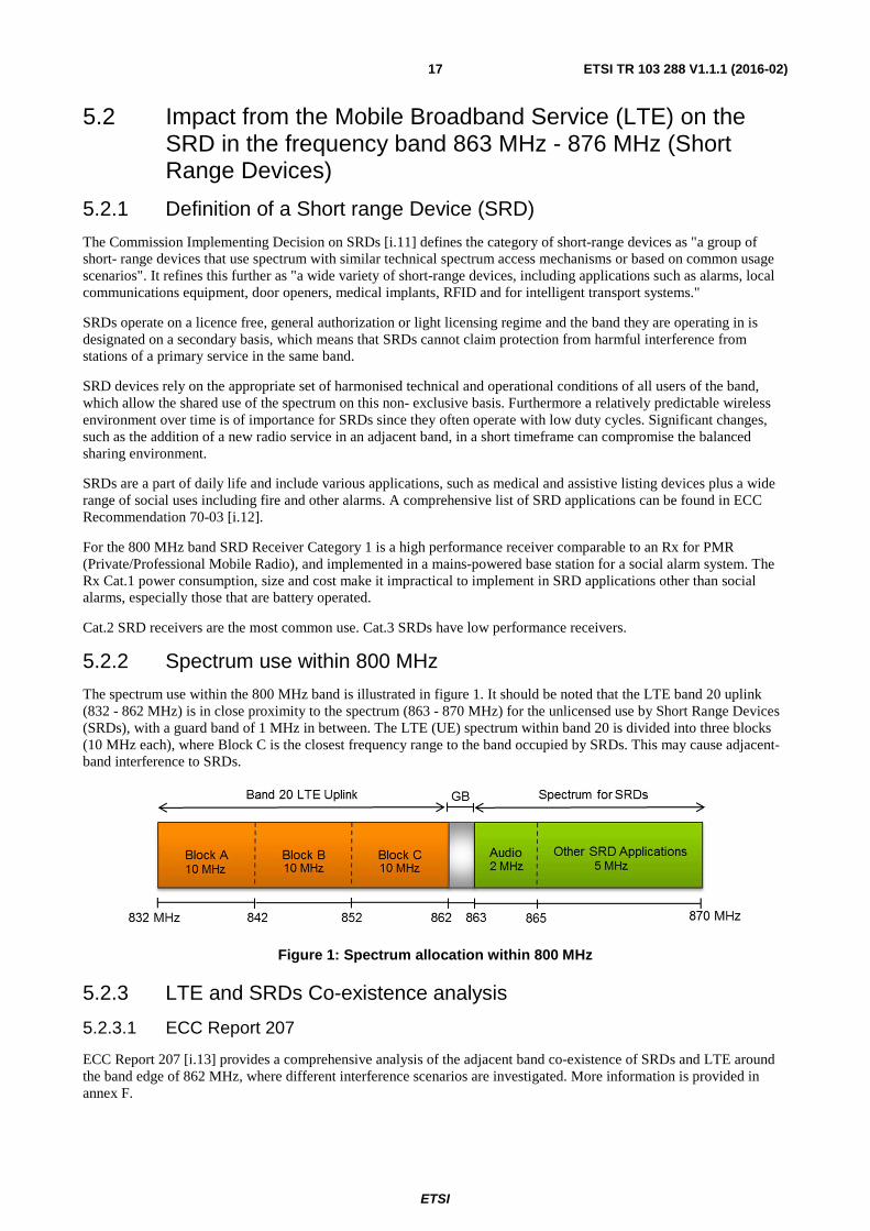
5.2.2 Spectrum use within 800 MHz
The spectrum use within the 800 MHz band is illustrated in figure 1. It should be noted that the LTE band 20 uplink (832 - 862 MHz) is in close proximity to the spectrum (863 - 870 MHz) for the unlicensed use by Short Range Devices (SRDs), with a guard band of 1 MHz in between. The LTE (UE) spectrum within band 20 is divided into three blocks (10 MHz each), where Block C is the closest frequency range to the band occupied by SRDs. This may cause adjacent-band interference to SRDs.
Figure 1: Spectrum allocation within 800 MHz
5.2.3 LTE and SRDs Co-existence analysis
5.2.3.1 ECC Report 207
ECC Report 207 [i.13] provides a comprehensive analysis of the adjacent band co-existence of SRDs and LTE around the band edge of 862 MHz, where different interference scenarios are investigated. More information is provided in annex F.
ETSI
ETSI TR 103 288 V1.1.1 (2016-02) 18
The three different categories (Cat.1 through Cat.3) of SRDs were considered for the investigation, reflecting different performance classes of the SRD receivers.
The major effects identified in ECC Report 207 [i.13] are:
1) Receiver blocking: The SRD receiver is unable to operate in the presence of a strong signal on a nearby frequency.
2) Out of band energy from the LTE User Equipment (UE): Since this appears within the bandwidth of the SRD receiver it cannot be filtered. It can prevent the operation of SRDs, especially in cases of low wanted signals.
The performance impact on the Cat.3 SRD receivers is mainly due to the poor SRD receiver blocking performance and cannot be improved by reducing the LTE OOB emissions. Additionally, for the Cat.1 SRDs, the dominant performance impact may result from the LTE OOB emissions, depending on the particular LTE UE emission mask. In case of the Cat.2 SRDs, the impact on performance is a result of both the OOB emissions level of LTE and the SRD receiver blocking performance.
According to ECC Report 207 [i.13], in-band noise may result in reduction of operational range (see annex F).
5.2.3.2 Additional simulation analysis from ETSI ERM/MSG TFES
ECC Report 207 [i.13] identifies a risk of harmful interference due to the blocking characteristics of SRDs and the OOB emission of LTE UEs.
In order to reduce the risk of interference an improvement of the SEM of LTE UEs by 3 dB is proposed (see annex F). Further studies have been performed and it has been shown that LTE UEs which fulfil the parameters used in the studies will provide a better protection to SRDs with the proposed improvement.
Additionally interference from LTE UEs towards SRDs is reduced even further due to the following effects reducing LTE emissions:
• The LTE UE is not transmitting at full power as this is only needed far away from the base station and/or at high data rates. Out of band emissions are significantly reduced with lower output power.
• The LTE UE only transmits a few resource blocks, not full allocation, since there are many other LTE UEs in the same cell using the other RBs. In most cases the number of RBs transmitted is below 5. This reduces OOB emissions significantly because the intermodulation products do not fall outside the band anymore.
• The LTE UE transmits in many cases the RBs not at the channel edge towards the SRD band but also at other locations inside the LTE bandwidth. This reduces out of band emissions significantly because the intermodulation products do not fall outside the band anymore.
• Only one operator has the channel close to the SRD band, so a device of another operator will not cause interference except in the case of ALDs.
• There are several other bands that are used by LTE UEs. Band 20 is mainly used to get coverage in the countryside, so in urban areas other bands that do not create interference are usually used (band 3 and 7 for example).
• Most of the time a LTE UE is not transmitting at all.
5.2.4 Experience of the LTE800 network deployment in France
LTE800 networks have been widely deployed in Europe since 2011. Few interference cases on SRDs have been reported. Two French mobile operators have provided the information that during the LTE800 deployment in France only one SDR interference case which was caused by the SRD device receiver blocking was reported. No interference case was reported due to LTE800 terminal out of band emissions. This situation of no interference case caused by UE out of band emission can be explained by multiple factors:
1) LTE800 UEs perform much better than the minimum requirement in the standards;
2) the probability of a LTE800 user using the whole channel bandwidth is quite small, when a terminal is using less number of resource blocks, its out of band emission is lower than the OOB levels defined in the Harmonised standard ETSI EN 301 908-13 [i.14];
ETSI
ETSI TR 103 288 V1.1.1 (2016-02) 19
3) the LTE uplink/downlink traffic ratio is about 1:10, as reported by some mobile operators described in ITU-R Report IMT, Beyond 2020 Traffic [i.15], this traffic asymmetry factor indicates that the LTE UE uplink activity factor is about 10 % to 15 %.
For more details please see annex D.
5.2.5 RFID
RFIDs tags are typically used in great numbers at a specific location e.g. on production lines to track items, for inventory management, asset tracking and to prevent theft of goods in shops.
RFID systems consist of 2 parts, the interrogator and the tag.
The interrogators receive the responses from the tags within the frequency range (fc ± 100) kHz to (fc ± 400) kHz,
where fc is the centre frequency of the selected high power channel. Within these frequencies the receivers in the
interrogators have sensitivities down to -85 dBm. They will therefore be susceptible to OOB emissions from LTE UEs. A report on a practical investigation into the effect of interference to RFID by OOB emissions from LTE UEs is available at annex G.
5.2.6 Improvements for SRDs
This clause will further analyse what could be done on the side of SRDs in order to contribute to better coexistence prospects.
The possibilities for the SRD industry to alleviate the interference situation are limited to improving the SRD technical performance of receivers in future produced mass-market equipment: the blocking performance and the selectivity (receiver mask). The SRD industry generally has no influence on the scenarios in which the equipment is and will be used. Furthermore, the use of advanced spectrum sharing mechanisms, such as Listen Before Transmit and Dynamic Frequency Selection, which are often used to improve co-existence between similar systems operating in unlicensed bands, may not offer much value in improving adjacent band coexistence with LTE due to the nature of wideband LTE unwanted emissions that cover the entire SRD band.
The ECC Report 207 [i.13] findings indicate among others that Cat.3 SRD receivers cannot coexist with nearby LTE UEs due to SRD receiver blocking effects and that the receiver performance degradation due to receiver selectivity (blocking) cannot be improved by reducing the interfering OOB emissions. Thus the removal of SRD receiver Cat.3 in the band 863 - 870 MHz from the market would reduce the risk of interference caused by blocking, but this alone is not sufficient.
Additionally ETSI TC ERM/TG28 is currently reviewing the structure of the receiver categories. Many manufacturers are already using receivers with better performance than defined in Cat.2. It therefore appears that Cat.2 may be the new base level in the 863 - 870 MHz band. A new category, which will define devices with parameters better than Cat.2, but below those of Cat.1 may also be introduced since the Cat.1 receiver is a high performance receiver which is impractical to implement in regular SRD applications, especially those that are battery operated.
In case of Cat.2 SRDs the impact on performance is the result of both the OOB emissions of LTE UEs and the SRD receiver blocking performance. In-band impact to SRDs (operational range reduction) from LTE UE OOB emissions can be improved by reducing those emissions in the SRD band.
5.2.7 Improvements for LTE UE
In order to reduce the risk of interference an improvement of the SEM of LTE UE by 3 dB is proposed (see annex F).
ETSI ERM/TFES will revise ETSI EN 301 908-13 [i.14] in order incorporate the proposed 3 dB improvement of the SEM in the SRD band (863 MHz - 870 MHz). For more information see clause 5.2.3.2.
5.3 Private/Professional Mobile Radio (PMR)
5.3.1 Wireless broadband relevant to PMR systems
At present there are no wireless mobile broadband systems that operate in spectrum immediately adjacent to PMR systems. Nevertheless, because the EC letter (see annex A) contains reference to the relevant bands and results are available, the analysis presented in annex H is informative in the potential case of a future expansion of frequency bands assigned to mobile broadband in the VHF/UHF range.
ETSI
ETSI TR 103 288 V1.1.1 (2016-02) 20
Clause H.1 shows details of some LTE test signals which have been used while evaluating potential interference to PMR systems. Immunity measurements are documented in clause H.2. The immunity of PMR equipment to LTE interference was found to be quite good, as would be expected from "professional" equipment.
In order to ensure good immunity to any future interference from LTE systems it is recommend that PMR co-existence standards [i.16] to [i.24] include receiver immunity requirements and those requirements should include intermodulation performance. The revision of the applicable standards is already planned in order to meet the requirements of the Radio Equipment Directive [i.25]. It is expected that the revision will include the re-implementation of receiver requirements that were partially removed when R&TTE [i.26] came into force.
Assuming the receiver specification issue is addressed, as expected, the most likely source with PMR-LTE co-existence problems is the emissions from LTE equipment in their OOB region. Such emissions should be studied further when considering acceptable co-existence but this cannot reasonably be done until frequency allocations, spectral masks, power levels, etc. are known for the relevant systems/spectrum.
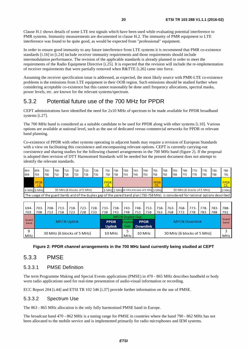
5.3.2 Potential future use of the 700 MHz for PPDR
CEPT administrations have identified the need for 2x10 MHz of spectrum to be made available for PPDR broadband systems [i.27].
The 700 MHz band is considered as a suitable candidate to be used for PPDR along with other systems [i.10]. Various options are available at national level, such as the use of dedicated versus commercial networks for PPDR or relevant band planning.
Co-existence of PPDR with other systems operating in adjacent bands may require a revision of European Standards with a view on facilitating this coexistence and encompassing relevant options. CEPT is currently carrying-out coexistence and sharing studies for the following channel arrangements in the 700 MHz band (figure 2). If the proposal is adopted then revision of DTT Harmonised Standards will be needed but the present document does not attempt to identify the relevant standards.
Figure 2: PPDR channel arrangements in the 700 MHz band currently being studied at CEPT
5.3.3 PMSE
5.3.3.1 PMSE Definition
The term Programme Making and Special Events applications (PMSE) in 470 - 865 MHz describes handheld or body worn radio applications used for real-time presentation of audio-visual information or recording.
ECC Report 204 [i.44] and ETSI TR 102 546 [i.37] provide further information on the use of PMSE.
5.3.3.2 Spectrum Use
The 863 - 865 MHz allocation is the only fully harmonised PMSE band in Europe.
The broadcast band 470 - 862 MHz is a tuning range for PMSE in countries where the band 790 - 862 MHz has not been allocated to the mobile service and is implemented primarily for radio microphones and IEM systems.
ETSI
ETSI TR 103 288 V1.1.1 (2016-02) 21
The allocation of the 790 - 862 MHz band to the mobile service has reduced this tuning range by 72 MHz and has brought PMSE equipment into close frequency and in many cases physical proximity with LTE base stations and especially UEs.
The coexistence of PMSE applications has been studied in CEPT Report 30 [i.5] and CEPT Report 32 [i.45].
5.3.4 Assistive Listening Devices (ALDs)
Assistive Listening Device (ALD) are systems utilizing electromagnetic, radio or light waves, or a combination of these, to transmit the acoustic signal from the sound source (a loudspeaker or a person talking) directly to the hearing impaired person.
Where ALDs are in use within the 863 - 865 MHz band, they will suffer blocking and out of band energy interference in the proximity of an LTE 800 UE. Unlike other SRDs these devices are worn in or adjacent to the ear canal.
Due to size and power limitations (single 1,5 V cell) no filtering is possible.
Industry is currently investigating if any improvements can be achieved.
6 Relevant harmonised standards
6.1 List of standards This clause refers to the relevant Harmonised Standards that need to be revised or developed in regards to the changes in the spectrum allocation in the 800 MHz and potentially 700 MHz bands.
Table 1: List of Harmonised Standards that need to be revised
Standard Title Actions pending End of work expected
Mobile
ETSI EN 301 908-13 [i.14]
IMT cellular networks; Harmonised EN covering the essential requirements of article 3.2 of the R&TTE Directive [i.26]; Part 13: Evolved Universal Terrestrial Radio Access (E-UTRA) User Equipment (UE).
Introduction of a 3 dB reduction on the SEM. Further information can be found in clause 5.2.
April 2015
Broadcasting
CENELEC EN 55020:2007 [i.2]
together with A11:2011
Sound and television broadcast receivers and associated equipment - Immunity characteristics - Limits and methods of measurement CISPR 20:2006.
CENELEC EN 55020 [i.2] will need to be replaced or revised depending on the progress of both CENELEC EN 55035 [i.36] and ETSI EN 302 296 [i.51], ETSI EN 303 340 [i.52], ETSI EN 303 345 [i.53].
FprEN 55035 Electromagnetic compatibility of multimedia equipment - Immunity requirements.
Draft CISPR 35 is currently in the voting process and the European equivalent, with its European Common Modifications, modify or replace CENELEC EN 55020 [i.2], and the European equivalent, with its European Common Modifications, when the draft is finally approved.
January 2016
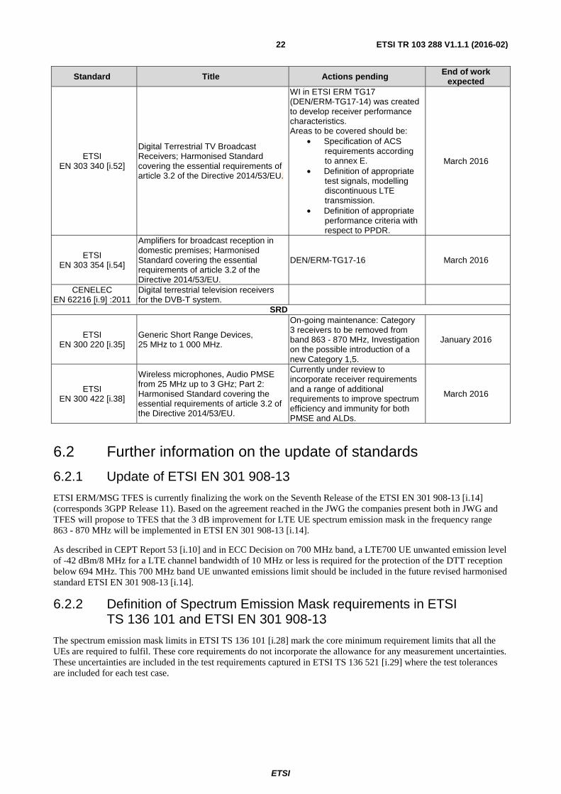
ETSI
ETSI TR 103 288 V1.1.1 (2016-02) 22
Standard Title Actions pending End of work expected
ETSI EN 303 340 [i.52]
Digital Terrestrial TV Broadcast Receivers; Harmonised Standard covering the essential requirements of article 3.2 of the Directive 2014/53/EU.
WI in ETSI ERM TG17 (DEN/ERM-TG17-14) was created to develop receiver performance characteristics. Areas to be covered should be:
• Specification of ACS requirements according to annex E.
• Definition of appropriate test signals, modelling discontinuous LTE transmission.
• Definition of appropriate performance criteria with respect to PPDR.
March 2016
ETSI EN 303 354 [i.54]
Amplifiers for broadcast reception in domestic premises; Harmonised Standard covering the essential requirements of article 3.2 of the Directive 2014/53/EU.
DEN/ERM-TG17-16 March 2016
CENELEC EN 62216 [i.9] :2011
Digital terrestrial television receivers for the DVB-T system.
SRD
ETSI EN 300 220 [i.35]
Generic Short Range Devices, 25 MHz to 1 000 MHz.
On-going maintenance: Category 3 receivers to be removed from band 863 - 870 MHz, Investigation on the possible introduction of a new Category 1,5.
January 2016
ETSI EN 300 422 [i.38]
Wireless microphones, Audio PMSE from 25 MHz up to 3 GHz; Part 2: Harmonised Standard covering the essential requirements of article 3.2 of the Directive 2014/53/EU.
Currently under review to incorporate receiver requirements and a range of additional requirements to improve spectrum efficiency and immunity for both PMSE and ALDs.
March 2016
6.2 Further information on the update of standards
6.2.1 Update of ETSI EN 301 908-13
ETSI ERM/MSG TFES is currently finalizing the work on the Seventh Release of the ETSI EN 301 908-13 [i.14] (corresponds 3GPP Release 11). Based on the agreement reached in the JWG the companies present both in JWG and TFES will propose to TFES that the 3 dB improvement for LTE UE spectrum emission mask in the frequency range 863 - 870 MHz will be implemented in ETSI EN 301 908-13 [i.14].
As described in CEPT Report 53 [i.10] and in ECC Decision on 700 MHz band, a LTE700 UE unwanted emission level of -42 dBm/8 MHz for a LTE channel bandwidth of 10 MHz or less is required for the protection of the DTT reception below 694 MHz. This 700 MHz band UE unwanted emissions limit should be included in the future revised harmonised standard ETSI EN 301 908-13 [i.14].
6.2.2 Definition of Spectrum Emission Mask requirements in ETSI TS 136 101 and ETSI EN 301 908-13
The spectrum emission mask limits in ETSI TS 136 101 [i.28] mark the core minimum requirement limits that all the UEs are required to fulfil. These core requirements do not incorporate the allowance for any measurement uncertainties. These uncertainties are included in the test requirements captured in ETSI TS 136 521 [i.29] where the test tolerances are included for each test case.
ETSI
ETSI TR 103 288 V1.1.1 (2016-02) 23
Following is an extract from ETSI TS 136 101 [i.28] which explains these aspects in the specification:
"4.1 Relationship between minimum requirements and test requirements
The Minimum Requirements given in this specification make no allowance for measurement uncertainty. The test specification TS 36.521-1 Annex F defines Test Tolerances. These Test Tolerances are individually calculated for each test. The Test Tolerances are used to relax the Minimum Requirements in this specification to create Test Requirements.
The measurement results returned by the Test System are compared - without any modification - against the Test Requirements as defined by the shared risk principle. The Shared Risk principle is defined in Recommendation ITU-R M.1545 [3]."
The test specification ETSI TS 136 521 [i.29] specifies both the conformance requirements which are the core requirements in table 6.6.2.1.3-1 of ETSI TS 136 521 [i.29], and also the test requirements which include the test tolerance in table 6.6.2.1.5-1. When these requirements are incorporated in the Harmonised Standard ETSI EN 301 908-13 [i.14], clause 4.3.2, only one set of requirements is mentioned. These requirements include the test tolerances as defined in clause 5.2 of ETSI EN 301 908-13 [i.14].
6.2.3 RFID standard ETSI EN 302 208
ETSI EN 302 208 [i.30] is the Harmonised Standard at UHF for RFID.
It was recently revised to incorporate the new band 915 - 921 MHz, which the ECC has recently designated for the operation of RFID, together with the band 865 - 868 MHz.
Originally ETSI EN 302 208 [i.30] was written to facilitate the co-existence of RFID systems and SRDs and with television operating below 862 MHz. With the introduction of LTE in the adjacent band and the resulting higher field strength levels, it became clear that the previous limits for the receiver parameters were no longer sufficient.
Subsequently it was decided to introduce significantly tighter limits for co-channel rejection, adjacent channel selectivity and blocking or desensitization. This resulted in the following values:
• Co-channel rejection: up to or equal to -35 dBm e.r.p.
• Adjacent channel selectivity: up to or equal to -26 dBm e.r.p.
• Blocking level of the equipment: equal to or greater than the following limits:
- For (fc ± 2 MHz) -23 dBm e.r.p.
- For (fc ± 5 MHz) -14 dBm e.r.p.
- For (fc ± 10 MHz) -8 dBm e.r.p.
These limits are included in the new version of ETSI EN 302 208 [i.30], which was approved by National Vote in February 2015.
6.2.4 Update of PMSE standards
ETSI EN 300 422 [i.38] and ETSI EN 300 454 [i.39] are the prime standards for radio microphones, In-Ear Monitors and assistive listening devices. Wideband audio links can be considered as higher power radio microphones. ETSI EN 300 357 [i.40] covers cordless audio, non-professional radio microphones and In-Ear Monitors.
None of the above mentioned PMSE standards have any receiver characteristics specified. Determining parameters for the wide range of professional and non-professional PMSE and cordless audio is challenging. In the case of ALD the small physical size and single 1,5 Volt cell power source adds an extra difficulty.
Currently ETSI EN 300 422 [i.38] is under review to incorporate receiver requirements and a range of additional requirements to improve spectrum efficiency and immunity for both PMSE and ALDs.
6.2.5 Update of PMR standards
In general it should be noted, that all Harmonised Standards need to be revised to meet the requirements of the RED [i.25]. During that process it is recommended that receiver parameters are fully re-instated, where applicable.
ETSI
ETSI TR 103 288 V1.1.1 (2016-02) 24
6.3 Need for a new harmonised radio standard Real-life experience of the roll-out of LTE800 networks in Europe shows that the interference from the LTE800 downlink to DTT reception is mainly caused by:
• DTT receiver selectivity and/or overloading.
• TV mast head amplifier overloading.
TV mast head amplifier overloading is the major source of interference from the LTE800 downlink to DTT reception below 790 MHz.
As described in CEPT Report 53 [i.10], the interference from the LTE700 downlink to DTT reception is quite similar to the case of interference from LTE800, only the frequency point for DTT receiver and/or TV mast head amplifier rejection is changed.
As described in ECC Report 138 [i.31] and ECC Report 148 [i.32], without a harmonised radio standard for TV receivers, there are important variances of TV receiver performance.
In order to mitigate the potential interference from LTE800 and LTE700 downlink to DTT reception and to improve the co-existence situation for more efficient spectrum use, under the RED, ETSI TC ERM TG17 has started to develop a harmonised radio standard for DTT receiver. In addition, the development of a harmonised radio standard for mast head amplifier is under discussion.
7 Remaining issues
7.1 Classification system for ready-made cable/connectors There remains a need for the European Commission to support the development of a voluntary classification system for ready-made retail cable/connectors.
7.2 Performance characteristics of TV connectors The appropriate CENELEC and ETSI Technical Committees are recommended to assess the performance characteristics for broadcast TV receiver connectors in order to identify the most appropriate connector type for future use.
7.3 Further RFID analysis The present document does not cover the specific RFID case of a tag occupying a total bandwidth of 600 kHz. It means that this case requires further investigation.
7.4 Further work on twisted pair wired systems Wired Systems i.e. twisted pair g.fast ([i.33] and [i.34]) operates up to 212 MHz and 800 MHz respectively. Consequently there may be the potential for interference due to the type of cables used in these higher frequencies.
8 Conclusion The interference situation between the mobile service and the existing services in the 800 MHz band was considered and is addressed in the present document.
NOTE: More detailed information on the interference assessment is provided in annexes B to I.
Initial assumptions were made for the future situation in the 700 MHz band, even though the new services in this band are not standardised yet.
Some issues for further investigation and also a need for a new standard for terrestrial TV mast head amplifiers were identified.
ETSI
ETSI TR 103 288 V1.1.1 (2016-02) 25
The resulting activities, which were also asked for by the EC letter (see annex A), are:
• ETSI EN 301 908-13 [i.14] will be updated with a SEM reduction of 3 dB.
• ETSI EN 300 220 [i.35] will be updated deleting the Cat.3 for the 863 - 870 MHz band. Cat.2 will therefore become the minimum performance and investigation on the possible introduction of a new category 1,5 are ongoing.
• New harmonised standards will be created for satellite and terrestrial broadcasting TV receivers.
• Cable networks were addressed under the work of JWG DD1 [i.1].
ETSI
ETSI TR 103 288 V1.1.1 (2016-02) 26
Annex A: Letter from the Commission
ETSI
ETSI TR 103 288 V1.1.1 (2016-02) 27
ETSI
ETSI TR 103 288 V1.1.1 (2016-02) 28
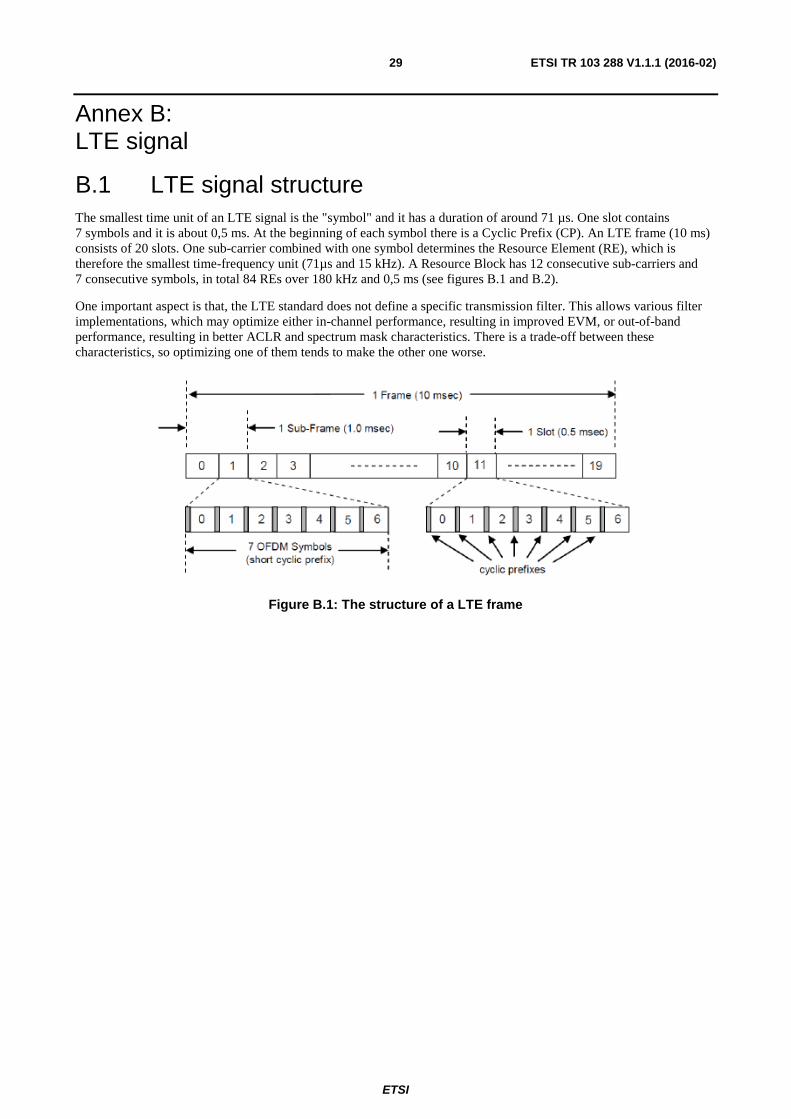
ETSI
ETSI TR 103 288 V1.1.1 (2016-02) 29
Annex B: LTE signal
B.1 LTE signal structure The smallest time unit of an LTE signal is the "symbol" and it has a duration of around 71 µs. One slot contains 7 symbols and it is about 0,5 ms. At the beginning of each symbol there is a Cyclic Prefix (CP). An LTE frame (10 ms) consists of 20 slots. One sub-carrier combined with one symbol determines the Resource Element (RE), which is therefore the smallest time-frequency unit (71µs and 15 kHz). A Resource Block has 12 consecutive sub-carriers and 7 consecutive symbols, in total 84 REs over 180 kHz and 0,5 ms (see figures B.1 and B.2).
One important aspect is that, the LTE standard does not define a specific transmission filter. This allows various filter implementations, which may optimize either in-channel performance, resulting in improved EVM, or out-of-band performance, resulting in better ACLR and spectrum mask characteristics. There is a trade-off between these characteristics, so optimizing one of them tends to make the other one worse.
Figure B.1: The structure of a LTE frame
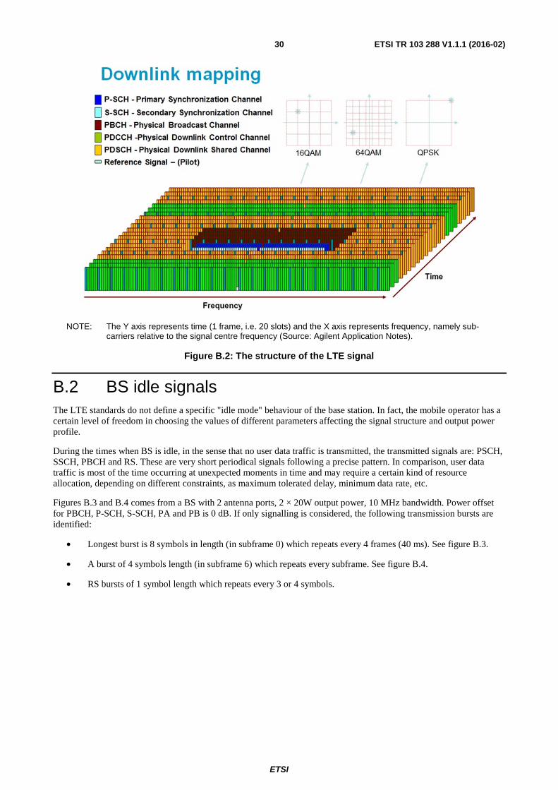
ETSI
ETSI TR 103 288 V1.1.1 (2016-02) 30
NOTE: The Y axis represents time (1 frame, i.e. 20 slots) and the X axis represents frequency, namely sub-carriers relative to the signal centre frequency (Source: Agilent Application Notes).
Figure B.2: The structure of the LTE signal
B.2 BS idle signals The LTE standards do not define a specific "idle mode" behaviour of the base station. In fact, the mobile operator has a certain level of freedom in choosing the values of different parameters affecting the signal structure and output power profile.
During the times when BS is idle, in the sense that no user data traffic is transmitted, the transmitted signals are: PSCH, SSCH, PBCH and RS. These are very short periodical signals following a precise pattern. In comparison, user data traffic is most of the time occurring at unexpected moments in time and may require a certain kind of resource allocation, depending on different constraints, as maximum tolerated delay, minimum data rate, etc.
Figures B.3 and B.4 comes from a BS with 2 antenna ports, 2 × 20W output power, 10 MHz bandwidth. Power offset for PBCH, P-SCH, S-SCH, PA and PB is 0 dB. If only signalling is considered, the following transmission bursts are identified:
• Longest burst is 8 symbols in length (in subframe 0) which repeats every 4 frames (40 ms). See figure B.3.
• A burst of 4 symbols length (in subframe 6) which repeats every subframe. See figure B.4.
• RS bursts of 1 symbol length which repeats every 3 or 4 symbols.

ETSI
ETSI TR 103 288 V1.1.1 (2016-02) 31
NOTE: BCH is repeated only every 4th frame. Synch signals are repeated every subframe. Rest of the subframes contain only RS signals (Source: Orange).
Figure B.3: Zoom over subframes 0 and 1
NOTE: This pattern is repeated every 40 ms. For a case when power is 2 × 40W the levels in this figure also doubles (Source: Orange).
Figure B.4: Power profile of the idle BS signal over 4 frames
From the visualizations above it is understood that the LTE signal during the idle and low load periods is mainly dominated by signalling, following a periodical pattern, when there is little or no traffic load. As the load increases the gaps between the signalling are filled and the power profile is more uniform. The mobile operator has also the option of introducing data broadcasting during times when there is no user traffic.
B.3 E-TM2 and E-TM2/"LTE_BS-idle_V2" comparison LTE standards define a number of test models which are utilized for testing of the base stations. E-UTRA test models (E-TM) are defined in clause 6 of ETSI TS 136 141 [i.41] for use in base station transmitter testing. The required physical channel parameters for each E-TM are quite detailed. Various control and data channels configurations are specified, along with their relative power levels. As a result of these differences, the E-TMs have somewhat different spectrum and power characteristics.
E-TM2 is a particular test model and has a high PAPR compared to all other E-TMs. While in the other E-TMs, all of the PRBs are allocated, in E-TM2 only one PDSCH PRB is allocated per slot and there is no power in the other PRBs (except for the RS). This would correspond to a case when only one user is connected to the base station. For this reason E-TM2 is the closest to the low loaded situation in real deployment. If the user data is eliminated from E-TM2 then a complete idle period is simulated. The representation of E-TM2 signal in power vs. time axis may look like in figure B.5, while the user data eliminated signal can be seen in figure B.6.
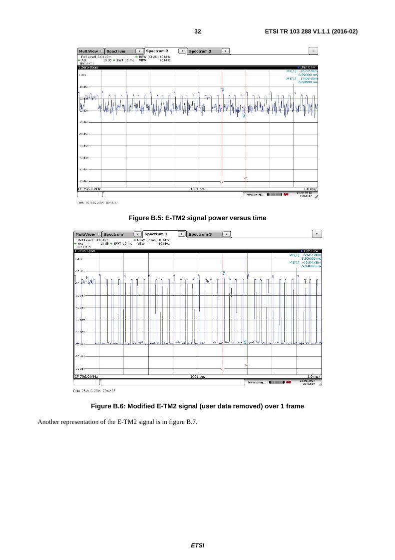
ETSI
ETSI TR 103 288 V1.1.1 (2016-02) 32
Figure B.5: E-TM2 signal power versus time
Figure B.6: Modified E-TM2 signal (user data removed) over 1 frame
Another representation of the E-TM2 signal is in figure B.7.
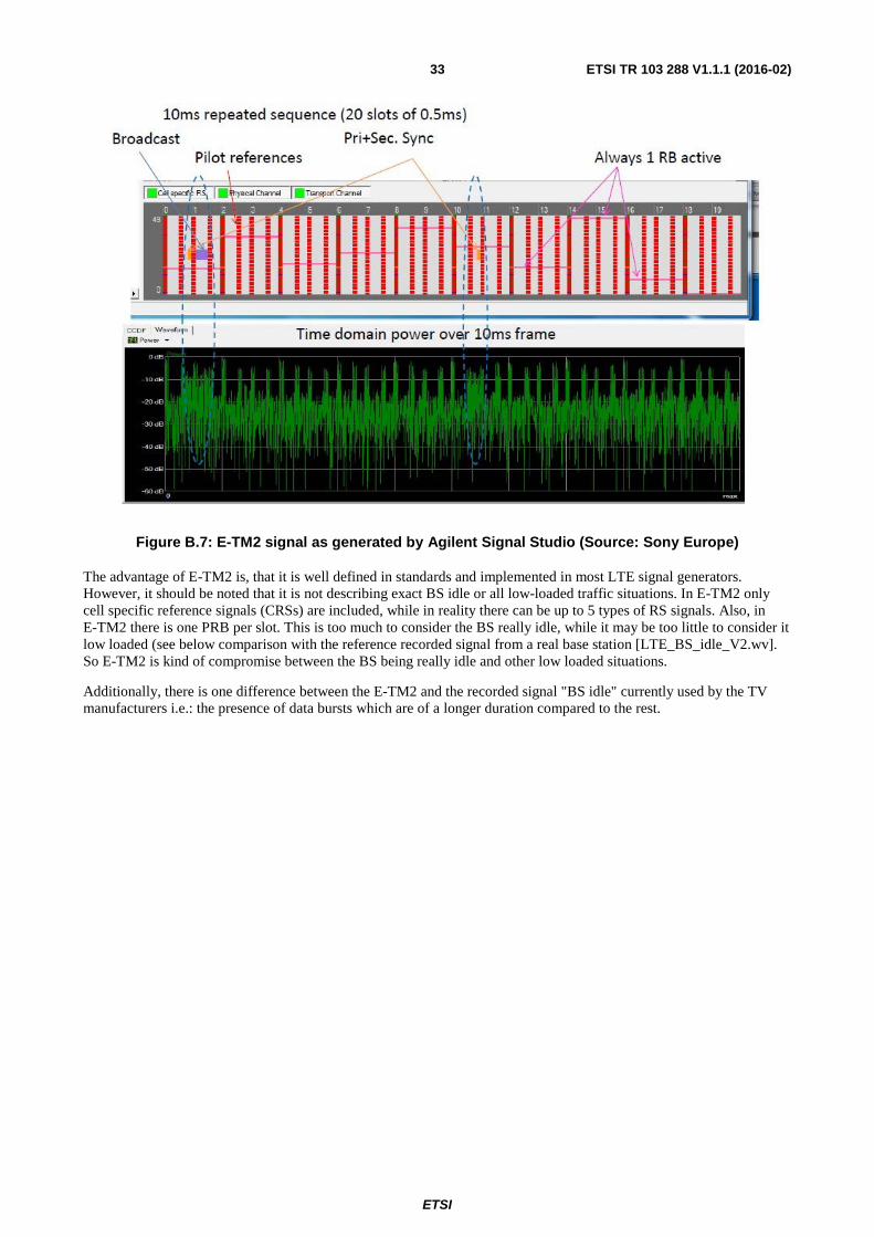
ETSI
ETSI TR 103 288 V1.1.1 (2016-02) 33
Figure B.7: E-TM2 signal as generated by Agilent Signal Studio (Source: Sony Europe)
The advantage of E-TM2 is, that it is well defined in standards and implemented in most LTE signal generators. However, it should be noted that it is not describing exact BS idle or all low-loaded traffic situations. In E-TM2 only cell specific reference signals (CRSs) are included, while in reality there can be up to 5 types of RS signals. Also, in E-TM2 there is one PRB per slot. This is too much to consider the BS really idle, while it may be too little to consider it low loaded (see below comparison with the reference recorded signal from a real base station [LTE_BS_idle_V2.wv]. So E-TM2 is kind of compromise between the BS being really idle and other low loaded situations.
Additionally, there is one difference between the E-TM2 and the recorded signal "BS idle" currently used by the TV manufacturers i.e.: the presence of data bursts which are of a longer duration compared to the rest.
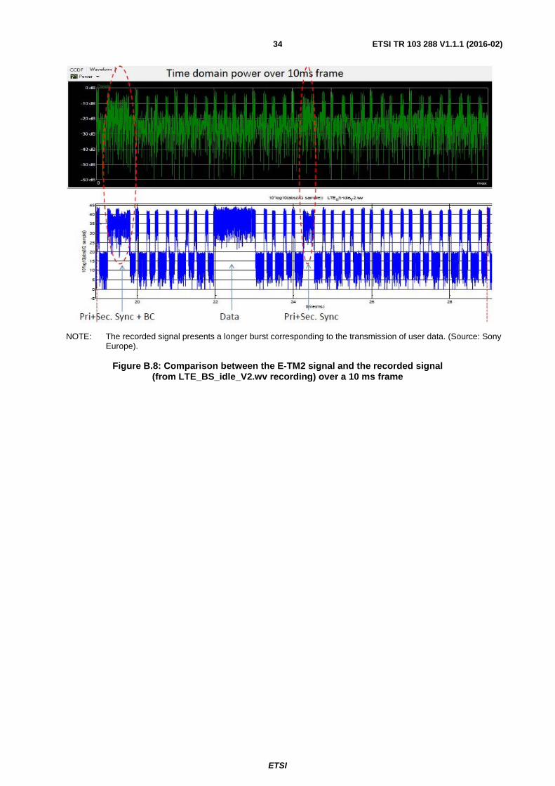
ETSI
ETSI TR 103 288 V1.1.1 (2016-02) 34
NOTE: The recorded signal presents a longer burst corresponding to the transmission of user data. (Source: Sony Europe).
Figure B.8: Comparison between the E-TM2 signal and the recorded signal
(from LTE_BS_idle_V2.wv recording) over a 10 ms frame
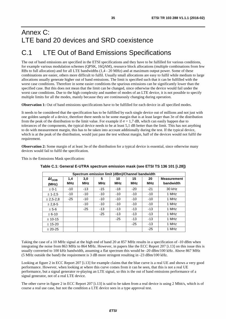
ETSI
ETSI TR 103 288 V1.1.1 (2016-02) 35
Annex C: LTE band 20 devices and SRD coexistence
C.1 LTE Out of Band Emissions Specifications The out of band emissions are specified in the ETSI specifications and they have to be fulfilled for various conditions, for example various modulation schemes (QPSK, 16QAM), resource block allocations (multiple combinations from few RBs to full allocation) and for all LTE bandwidths (1,4 - 20 MHz) and at maximum output power. Some of these combinations are easier, others more difficult to fulfil. Usually small allocations are easy to fulfil while medium to large allocations usually generate higher out of band emissions. The limit is specified such that it can be fulfilled with the worst case conditions. Therefore in some easier conditions the spurious emissions can be significantly lower than the specified case. But this does not mean that the limit can be changed, since otherwise the device would fail under the worst case conditions. Due to the high complexity and number of modes of an LTE device, it is not possible to specify multiple limits for all the modes, mainly because they are continuously changing during operation.
Observation 1: Out of band emissions specifications have to be fulfilled for each device in all specified modes.
It needs to be considered that the specification has to be fulfilled by each single device out of millions and not just with one golden sample of a device, therefore there needs to be some margin that is at least larger than 3σ of the distribution from the peak of the distribution to the limit value. For example if σ = 1,7 dB, which can easily happen due to tolerances of the components, the typical device needs to be at least 5,1 dB better than the limit. This has not anything to do with measurement margin, this has to be taken into account additionally during the test. If the typical device, which is at the peak of the distribution, would just pass the test without margin, half of the devices would not fulfil the requirement.
Observation 2: Some margin of at least 3σ of the distribution for a typical device is essential, since otherwise many devices would fail to fulfil the specification.
This is the Emissions Mask specification:
Table C.1: General E-UTRA spectrum emission mask (see ETSI TS 136 101 [i.28])
Spectrum emission limit (dBm)/Channel bandwidth ∆fOOB
(MHz)
1,4 MHz
3,0 MHz
5 MHz
10 MHz
15 MHz
20 MHz
Measurement bandwidth
± 0-1 -10 -13 -15 -18 -20 -21 30 kHz
± 1-2,5 -10 -10 -10 -10 -10 -10 1 MHz
± 2,5-2,8 -25 -10 -10 -10 -10 -10 1 MHz
± 2,8-5 -10 -10 -10 -10 -10 1 MHz
± 5-6 -25 -13 -13 -13 -13 1 MHz
± 6-10 -25 -13 -13 -13 1 MHz
± 10-15 -25 -13 -13 1 MHz
± 15-20 -25 -13 1 MHz
± 20-25 -25 1 MHz
Taking the case of a 10 MHz signal at the high end of band 20 at 857 MHz results in a specification of -10 dBm when integrating the noise from 863 MHz to 864 MHz. However, in papers like the ECC Report 207 [i.13] on this issue this is usually converted to 100 kHz bandwidth, assuming a flat spectrum this would be -20 dBm/100 kHz. Above 867 MHz (5 MHz outside the band) the requirement is 3 dB more stringent resulting in -23 dBm/100 kHz.
Looking at figure 2 in ECC Report 207 [i.13] for example claims that the blue curve is a real UE and shows a very good performance. However, when looking at where this curve comes from it can be seen, that this is not a real UE performance, but a signal generator re-playing an LTE signal, so this is the out of band emissions performance of a signal generator, not of a real LTE device.
The other curve in figure 2 in ECC Report 207 [i.13] is said to be taken from a real device is using 2 Mbit/s, which is of course a real use case, but not the condition a LTE device sees in a type approval test.
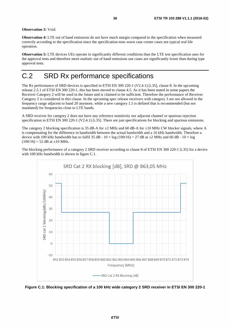
ETSI
ETSI TR 103 288 V1.1.1 (2016-02) 36
Observation 3: Void.
Observation 4: LTE out of band emissions do not have much margin compared to the specification when measured correctly according to the specification since the specification tests worst case corner cases not typical real life operation.
Observation 5: LTE devices UEs operate in significantly different conditions than the LTE test specification uses for the approval tests and therefore more realistic out of band emissions use cases are significantly lower than during type approval tests.
C.2 SRD Rx performance specifications The Rx performance of SRD devices is specified in ETSI EN 300 220-1 (V2.4.1) [i.35], clause 8. In the upcoming release 2.5.1 of ETSI EN 300 220-1, this has been moved to clause 4.5. As it has been stated in some papers the Receiver Category 2 will be used in the future and is claimed to be sufficient. Therefore the performance of Receiver Category 2 is considered in this clause. In the upcoming spec release receivers with category 3 are not allowed in the frequency range adjacent to band 20 anymore, while a new category 1.5 is defined that is recommended (but not mandated) for frequencies close to LTE bands.
A SRD receiver for category 2 does not have any reference sensitivity nor adjacent channel or spurious rejection specification in ETSI EN 300 220-1 (V2.4.1) [i.35]. There are just specifications for blocking and spurious emissions.
The category 2 blocking specification is 35 dB-A for ±2 MHz and 60 dB-A for ±10 MHz CW blocker signals, where A is compensating for the difference in bandwidth between the actual bandwidth and a 16 kHz bandwidth. Therefore a device with 100 kHz bandwidth has to fulfil 35 dB - 10 × log (100/16) = 27 dB at ±2 MHz and 60 dB - 10 × log (100/16) = 52 dB at ±10 MHz.
The blocking performance of a category 2 SRD receiver according to clause 8 of ETSI EN 300 220-1 [i.35] for a device with 100 kHz bandwidth is shown in figure C.1.
Figure C.1: Blocking specification of a 100 kHz wide category 2 SRD receiver in ETSI EN 300 220-1
ETSI
ETSI TR 103 288 V1.1.1 (2016-02) 37
The specification of an SRD device RX at the channel closest to LTE band 20 at 863,05 MHz shows 27 dB of rejection inside most of the highest 10 MHz channel in LTE band 20. Additionally it needs to be considered that the specification just asks for a CW interferer (unmodulated). In case of a direct conversion receiver this makes it much easier to fulfil the blocking requirement, because second order intermodulation effects that can happen due to the significant amplitude modulation of the interferer do not disturb the reception at all. With a modulated blocker having a significant amplitude modulation like a LTE carrier, most likely the blocking performance of a direct conversion SRD receiver would therefore be worse.
As there is only 1 MHz frequency difference between the LTE band 20 UL and the SRD band, also a SAW filter covering the whole SRD band with a pass band of 863 - 870 MHz does not help to improve blocking against an LTE signal below 862 MHz, since SAW filters in this frequency range need a larger transition band from pass band to stop band in the order of 6 - 10 MHz. This can be confirmed by checking SAW filter specs, where it can clearly be seen that at the upper edge of the LTE band 20 UL where the PUCCH is located the SRD receiver SAW has almost no rejection. Only if the SAW filter does not cover the whole SRD band but only a small portion at the upper end, a significant rejection of the LTE signals can be achieved by the SAW filter.
The LTE UE TX has the same issue, also there the built in duplexer does not really help to reduce LTE UE TX noise in the SRD band.
ETSI
ETSI TR 103 288 V1.1.1 (2016-02) 38
Annex D: Experience of LTE800 networks deployment in France Three LTE800 mobile licences have been given by the national regulator at the end of 2011, the detail information related to the 800 MHz band licences can be found at LTE 800 licences France [i.50].
LTE800 network deployment has not been very fast due to the fact that cases of DTT interference (TV power amplifier overloading) were declared, for each declared DTT interference case, an external filter is installed before the DTT power amplifier, all of the declared interference cases are solved by installing an external band pass filter on TV antenna mast, but it delayed the speed of LTE800 network deployment.
Until end of October 2014, there were 6 725 LTE800 radio sites in service, more than 10 000 LTE800 radio sites agreed, detail information of LTE800 radio sites can be found at LTE 800 radio sites [i.49].
Although many cases of DTT interference were identified, almost all due to TV power amplifier overloading, during LTE800 network deployment, only one interference case with SRD above 863 MHz was identified, it was caused by SRD receiver blocking imperfection, since the interference was caused by LTE800 BS in-band transmission; the problem was solved by the owner of the SRD system by external filter and site engineering solutions. No SRD interference case was identified as being caused by UE out of band emissions.
Even in ECC Report 207 [i.13], it was concluded that LTE800 UE out of band emission based on the minimum requirement of UE spectrum mask may not be sufficient for protecting SDRs operation above 863 MHz, the field experience of LTE800 network deployment in France shows that there was no SRD interference case identified. SRDs' frequency bands is unlicensed and placed under a no interference/no protection regulatory regime vis à vis any other authorized services in the band or in other bands.
By considering that there is no interference in the field due to LTE800 UE Out of band emissions, 800 MHz band is a coverage frequency band, LTE800 link budget is limited on uplink, any reduction of UE out of band emission does not create any burden on UE Tx power, nor on UE handset cost. It is mandatory for operators to keep link budget unchanged as business plans from operators.
It is highly recommended to perform all necessary adjacent band compatibility studies before a frequency band, e.g. 700 MHz, is licensed. Any similar post-license adjacent band compatibility study situation, such as between LTE2600 and Radar (ECC Report 174 [i.46]), between LTE800 and SRDs (ECC Report 207 [i.13]) should be avoided.
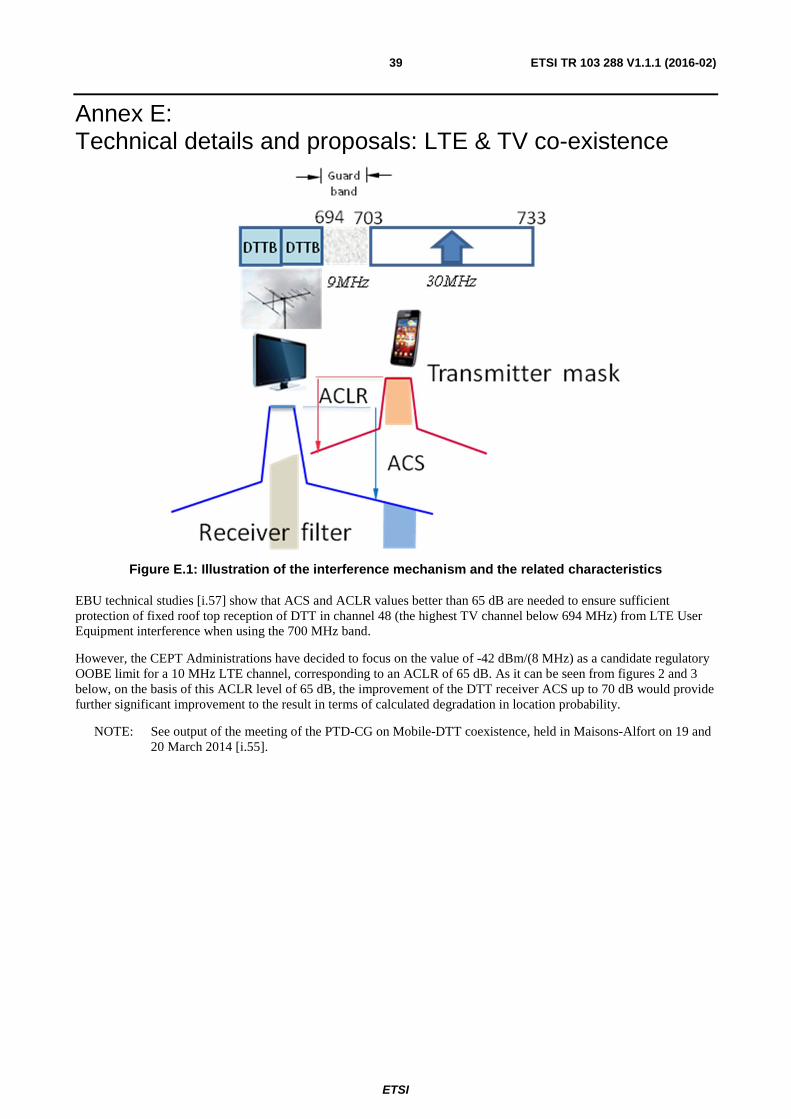
ETSI
ETSI TR 103 288 V1.1.1 (2016-02) 39
Annex E: Technical details and proposals: LTE & TV co-existence
Figure E.1: Illustration of the interference mechanism and the related characteristics
EBU technical studies [i.57] show that ACS and ACLR values better than 65 dB are needed to ensure sufficient protection of fixed roof top reception of DTT in channel 48 (the highest TV channel below 694 MHz) from LTE User Equipment interference when using the 700 MHz band.
However, the CEPT Administrations have decided to focus on the value of -42 dBm/(8 MHz) as a candidate regulatory OOBE limit for a 10 MHz LTE channel, corresponding to an ACLR of 65 dB. As it can be seen from figures 2 and 3 below, on the basis of this ACLR level of 65 dB, the improvement of the DTT receiver ACS up to 70 dB would provide further significant improvement to the result in terms of calculated degradation in location probability.
NOTE: See output of the meeting of the PTD-CG on Mobile-DTT coexistence, held in Maisons-Alfort on 19 and 20 March 2014 [i.55].
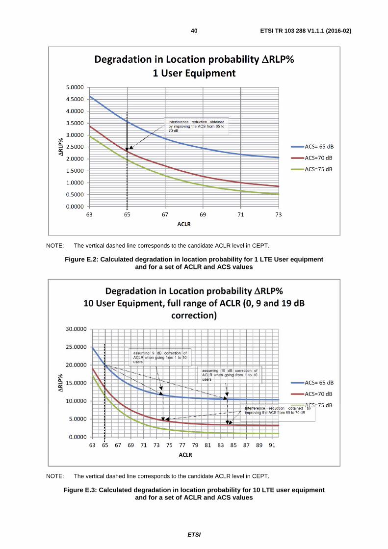
ETSI
ETSI TR 103 288 V1.1.1 (2016-02) 40
NOTE: The vertical dashed line corresponds to the candidate ACLR level in CEPT.
Figure E.2: Calculated degradation in location probability for 1 LTE User equipment and for a set of ACLR and ACS values
NOTE: The vertical dashed line corresponds to the candidate ACLR level in CEPT.
Figure E.3: Calculated degradation in location probability for 10 LTE user equipment and for a set of ACLR and ACS values
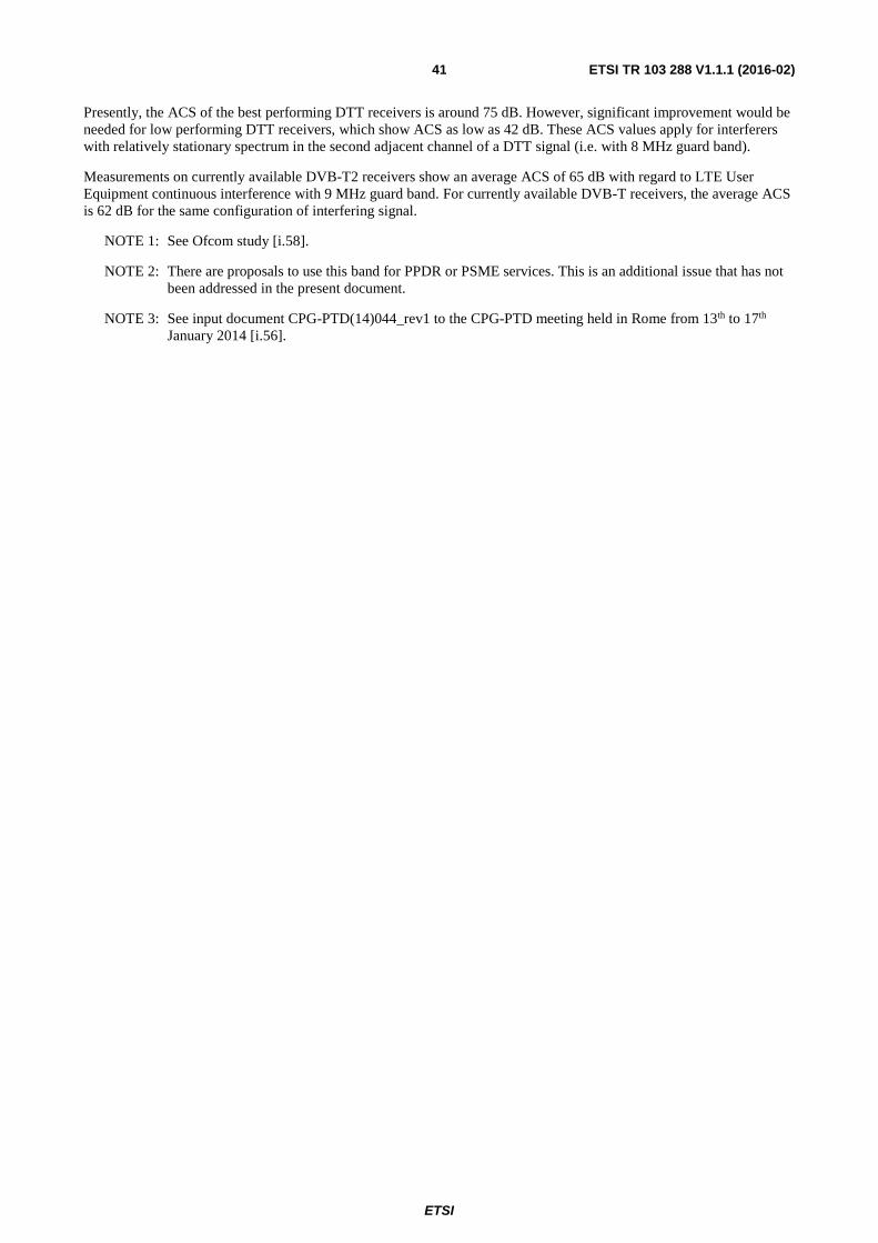
ETSI
ETSI TR 103 288 V1.1.1 (2016-02) 41
Presently, the ACS of the best performing DTT receivers is around 75 dB. However, significant improvement would be needed for low performing DTT receivers, which show ACS as low as 42 dB. These ACS values apply for interferers with relatively stationary spectrum in the second adjacent channel of a DTT signal (i.e. with 8 MHz guard band).
Measurements on currently available DVB-T2 receivers show an average ACS of 65 dB with regard to LTE User Equipment continuous interference with 9 MHz guard band. For currently available DVB-T receivers, the average ACS is 62 dB for the same configuration of interfering signal.
NOTE 1: See Ofcom study [i.58].
NOTE 2: There are proposals to use this band for PPDR or PSME services. This is an additional issue that has not been addressed in the present document.
NOTE 3: See input document CPG-PTD(14)044_rev1 to the CPG-PTD meeting held in Rome from 13th to 17th January 2014 [i.56].
ETSI
ETSI TR 103 288 V1.1.1 (2016-02) 42
Annex F: Impact from the Mobile Broadband Service (LTE) on the SRD in the frequency band 863 MHz - 876 MHz (Short Range Devices) - TRP modelling and simulation results
F.1 LTE and SRDs Co-existence analysis in ECC Report 207
ECC Report 207 [i.13] provides a comprehensive analysis of the adjacent band co-existence of SRDs and LTE within the 800 MHz band, where different interference scenarios are investigated. In particular, the ECC Report 207 captures an analytical and simulation analysis for the scenarios where LTE UEs are operating in close proximity of the SRD receiver and may potentially cause interference to SRDs. The scenarios investigated include:
1) "Same room" scenario: where a single LTE UE is allocated the entire 10 MHz of block C (852 - 862 MHz) and is transmitting within 10 m range of a SRD which is receiving at the same time.
2) "Macro" scenario: where one SRD receiver and LTE UE(s) are randomly located in a 3-cell LTE network, with no specific assumptions on the relative position between SRD and LTE UE. The interference risk under this scenario was not considered critical and was not addressed in the further discussions.
Three different categories (Cat.1 through Cat.3) of SRDs were considered for the investigation, reflecting different performance classes of the SRD receivers. Table F.1 is an excerpt from the ECC Report 207 [i.13] that illustrates a summary of the results, capturing the impact of LTE OOBE that cause interference to the SRDs and the performance impact due to the blocking (Rx sensitivity) characteristics of the SRD receivers.
Table F.1: Summary of Results for the same room scenario [Excerpt from ECC Report 207 [i.13]]
LTE UE mask Cat.3 SRD Receiver Cat.2 SRD Receiver Cat.1 SRD receiver
(note 1) According ETSI TS 136 101 [i.28] with 1,4/3/5/10 MHz bandwidth (note 2)
The probability of interference was found to be in the range 10 % and 42 %.
The probability of interference was found to be in the range 5 % to 31 %.
The probability of interference was found to be in the range 2 % to 29 %.
According to a measured mask from a real LTE UE implementation with 10 MHz bandwidth [i.13]
The probability of interference was found to be in the range 16 % and 41 %.
The probability of interference was found to be in the range 5 % to 17 %.
The probability of interference was found to be in the range 2 % to 7 %.
Comments The main issue is blocking.
The prevailing component can be blocking or in-band interference, depending on the considered LTE UE emission mask.
The dominant effect is in-band interference from OoB emissions, depending on the considered LTE UE emission mask.
NOTE 1: The SRD Receiver Category 1 is a high performance receiver comparable to an Rx for PMR (Professional Mobile Radio) and implemented by social alarm power supplied base station. The Rx Cat.1 power consumption, size and cost (all elements very critical for SRDs) make it impractical for regular SRD applications, especially considering that the utmost of them are battery operated.
NOTE 2: It has to be noted that in the present document the LTE UE Tx mask was used in accordance to ETSI TS 136 101 [i.28] which shows 1,5 dB lower power values as the harmonised standard ETSI EN 301 908-13 [i.14]. However, the impact on the result is only marginal.
NOTE: For the additional explanation of the note 2 of the table F.1 please see the clause 5.2.2.
An interference probability of below 5 % can therefore generally be reached at the expense of a reduction in SRD operating distance.
• Cat.2 receiver at 863,1 MHz (LTE 10 MHz mask) = reduction from 40 m to 21 m (-48 %);
ETSI
ETSI TR 103 288 V1.1.1 (2016-02) 43
• Cat.2 receiver at 869 MHz (LTE 10 MHz mask) = reduction from 40 m to 24 m (-40 %);
• Cat.2 receiver at 863,1 MHz (with a measured mask from a real LTE UE implementation) = reduction from 40 m to 28 m (-30 %);
• Cat.2 receiver at 863,1 MHz (LTE 1,4 MHz mask) reduction from 40 m to 30 m (-25 %);
• Cat.2 receiver at 865 MHz (LTE 1,4 MHz and a measured mask from a real LTE UE implementation) reduction from 40 m to 38 m (-5 %).]
Reference to ECC Report 207 [i.13] for the measurements done for real LTE UEs.
As observed in table F.1, the probability of LTE OOBE interference to the SRD receivers can vary significantly depending on the simulation methodology, deployment scenario, assumptions about the LTE UE emission mask, and the blocking performance of the SRD receivers. In the following discussion, the simulation methodology and assumptions made in ECC Report 207 [i.13] are reviewed and additional results are provided to capture realistic co-existence scenarios for LTE and SRD deployments within the 800 MHz band.
F.2 Review of Simulation analysis in ECC Report 207
F.2.1 Assumptions on the SRD wanted signal distribution (dRSS) It is noted that ECC Report 207 [i.13] considers two different approaches to model the wanted signal of the victim link (i.e. the signal between the SRD TX and the SRD RX).
1) dRSS Approach 1: In this approach, the SRD wanted signal is a user defined value with a mean dRSS 20 dB (Gaussian distributed with standard deviation of 10 dB) above sensitivity.
Observations: In this approach the distance between the SRD TX and SRD RX that results from the simulator deployment is not considered, rather a fixed user defined value is overridden. This fixed value is based on the sensitivity level of the SRD receiver and represents the case where the SRD TX is always at a fixed distance from the SRD RX, despite the actual physical distance that results from the simulation. This approach does not follow the Monte-Carlo simulation methodology where the UEs/SRDs are placed randomly within a certain area and the signal strength from the UEs/SRDs is based on the distance between them. Following the dRSS approach 1 means that, while the LTE (interferer) UEs are dropped randomly within 10 meters of the SRD receiver, the SRD TX is far away from the SRD receiver. This does not lead to a weak SRD received (or wanted) signal and a strong LTE interfering signal.
2) dRSS Approach 2: In this approach, the SRD wanted signal is generated from the simulator deployment and considers the statistical random deployment of the SRDs.
Observations: In this approach, the distance between the SRDs is based on the statistical random deployment. This means that, in some cases, the SRD TX may be close to the SRD RX and in some cases the SRD TX may be far away from the SRD RX (based on the typical operating distance). Similarly, the LTE (interferer) UEs are also randomly dropped within 10 meters of the SRD receiver. This approach is in line with the Monte-Carlo simulation methodology where no restrictions are applied on the generation of the wanted signal and the random deployment caters for both the typical operating range and the maximum operating range of the SRDs.
F.2.2 Number of LTE (interfering) UEs in 10 MHz The number of LTE (interfering) UEs assumed in the simulations has a significant impact on the performance of the SRD victim receivers. The number of UEs within the given spectrum (10 MHz) determines the bandwidth allocation per UE. Furthermore, lower bandwidth allocations per UE result in lower OOB emissions as per the Spectrum Emission Mask (SEM) and the Adjacent Channel Leakage Ratio (ACLR) requirements. ECC Report 207 [i.13] considers several different scenarios when it comes to the number of LTE UEs that cause interference to the SRD victim receiver. These scenarios are captured in table F.2, where the number of LTE UEs assumed within the simulations range from 1 UE to 5 UEs per 10 MHz. This is one of the main reasons for the large variation observed in the simulation results summarized in table F.1.
ETSI
ETSI TR 103 288 V1.1.1 (2016-02) 44
Table F.2: Assumed number of UEs in different scenarios in ECC Report 207
Parameters Assumptions for different scenarios LTE UEs per 10 MHz 1 2 3 5 UE TX bandwidth 10 MHz 5 MHz 3 MHz 1,4 MHz
It is further noted that the upper limit (or worst case) in the probability of interference experienced by the SRD receivers (as captured in ECC Report 207 [i.13]) is marked by the theoretical scenario where all the frequency and time resources available within the cell area are allocated to one single UE (i.e. 50 RBs to one UE for an indefinite period). This scenario considers a 10 MHz emission mask for LTE UE and leads to higher OOBE leakage power which generates pessimistic results.
As per the simulation methodology agreed in 3GPP (in ETSI TR 136 942 [i.42]), it is concluded that such co-existence simulations are generally performed with 3 active UEs within the simulated bandwidth of 10 MHz (i.e. ~3 MHz/UE in this case) to appropriately model the interference and its statistical impact in the simulation results.
It is further concluded within ECC Report 207 [i.13]:
"The LTE UE devices compliant with mask from ETSI TS 136 101 with 1.4 MHz bandwidth may not produce harmful interference. However, LTE is a complex technology and it is expected that the resource block allocation and thus the used bandwidth will be dynamically changing over short periods of time. The consequence is that all masks/bandwidths are expected to be used at any location but with different occurrence probabilities in time (e.g. higher probability of small resource block allocations vs. lower probability of high resource block allocations). In a real network typically 3-5 UEs are scheduled in each transmission time interval sharing the 10 MHz channel bandwidth. Therefore, the result for the bandwidths of 1.4 MHz and 3 MHz represents the likely impact of LTE UE on SRDs. The precise interference effect of this dynamic LTE behaviour will also depend on the characteristics of the SRDs: e.g. audio links may experience constantly recurring interference effects while SRDs using digital modulations may be better able to resist (e.g. FEC, acknowledgement)."
Hence, in order to consider a more realistic worst case scenario, the number of LTE (interfering) UEs within the 10 MHz spectrum should be 3 to 5 UEs, that are dropped randomly within the 10 meter distance from the SRD receiver.
F.2.3 Activity Factor of the LTE (interfering) UEs The activity factor of the LTE (interfering) UEs in the simulation determines how often the UEs is actively transmitting on their scheduled RBs and cause interference to the SRD receivers. The activity factor of 100 % means that the UEs is transmitting indefinitely throughout the simulation period. However, under a more realistic simulation scenario, the activity factor of the LTE UEs needs to be taken in to account, which will result in lower interference to the SRD victim receiver. This is also noted as part of the conclusions of ECC Report 207 [i.13] as follows:
"In addition it should be noted that the numerical results of studies provided in this report are based on assumption that the LTE UE is permanently transmitting (100 % activity factor). Therefore, the probability of receiving interference will statistically be reduced by a factor approximating the actual activity of the LTE UE transmissions. Here it should be considered that data uploading is not necessarily connected to an end user action at the same location (e.g. watching videos from a home NAS via an LTE link)."
Furthermore, as shown in figure 1, the Band 20 UL is divided into three blocks (Block A, B and C). The simulation analysis in ECC Report 207 only considers the use of block C or part of the block C. Considering the likelihood that the UE can be scheduled in block A or block B should further lead to lower OOB emissions interference from LTE UEs. The conclusions of ECC Report 207 [i.13] note that:
"In this study, only the probability of interference when the LTE UE is using block C or part of block C was considered. Therefore it was not taken into account that the UE can be using other bands or other blocks in the 800 MHz band. The likelihood of using block C is therefore not factored in the above results .This likelihood depends on several factors that can vary over time: for example, the network planning and loading, the number of mobile operators in the country, and on the overall availability of spectrum for mobile communications."
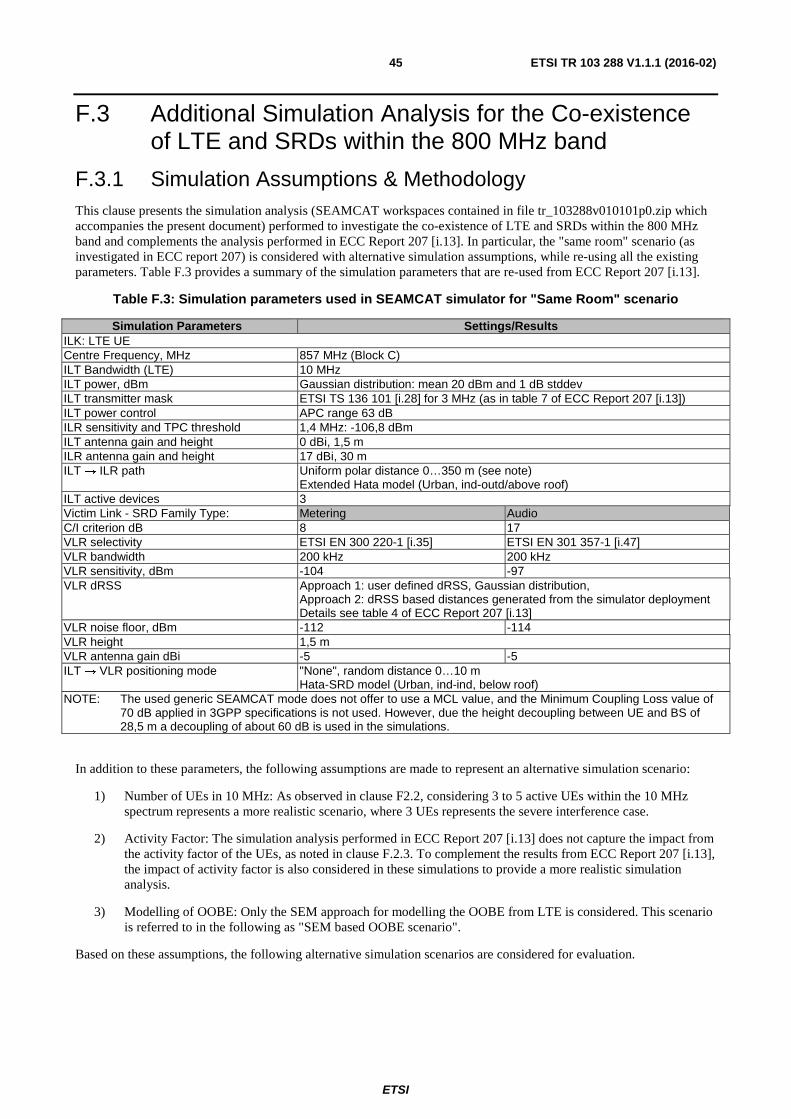
ETSI
ETSI TR 103 288 V1.1.1 (2016-02) 45
F.3 Additional Simulation Analysis for the Co-existence of LTE and SRDs within the 800 MHz band
F.3.1 Simulation Assumptions & Methodology This clause presents the simulation analysis (SEAMCAT workspaces contained in file tr_103288v010101p0.zip which accompanies the present document) performed to investigate the co-existence of LTE and SRDs within the 800 MHz band and complements the analysis performed in ECC Report 207 [i.13]. In particular, the "same room" scenario (as investigated in ECC report 207) is considered with alternative simulation assumptions, while re-using all the existing parameters. Table F.3 provides a summary of the simulation parameters that are re-used from ECC Report 207 [i.13].
Table F.3: Simulation parameters used in SEAMCAT simulator for "Same Room" scenario
Simulation Parameters Settings/Results ILK: LTE UE Centre Frequency, MHz 857 MHz (Block C) ILT Bandwidth (LTE) 10 MHz ILT power, dBm Gaussian distribution: mean 20 dBm and 1 dB stddev ILT transmitter mask ETSI TS 136 101 [i.28] for 3 MHz (as in table 7 of ECC Report 207 [i.13]) ILT power control APC range 63 dB ILR sensitivity and TPC threshold 1,4 MHz: -106,8 dBm ILT antenna gain and height 0 dBi, 1,5 m ILR antenna gain and height 17 dBi, 30 m ILT → ILR path Uniform polar distance 0…350 m (see note)
Extended Hata model (Urban, ind-outd/above roof) ILT active devices 3 Victim Link - SRD Family Type: Metering Audio C/I criterion dB 8 17 VLR selectivity ETSI EN 300 220-1 [i.35] ETSI EN 301 357-1 [i.47] VLR bandwidth 200 kHz 200 kHz VLR sensitivity, dBm -104 -97 VLR dRSS Approach 1: user defined dRSS, Gaussian distribution,
Approach 2: dRSS based distances generated from the simulator deployment Details see table 4 of ECC Report 207 [i.13]
VLR noise floor, dBm -112 -114 VLR height 1,5 m VLR antenna gain dBi -5 -5 ILT → VLR positioning mode "None", random distance 0…10 m
Hata-SRD model (Urban, ind-ind, below roof) NOTE: The used generic SEAMCAT mode does not offer to use a MCL value, and the Minimum Coupling Loss value of
70 dB applied in 3GPP specifications is not used. However, due the height decoupling between UE and BS of 28,5 m a decoupling of about 60 dB is used in the simulations.
In addition to these parameters, the following assumptions are made to represent an alternative simulation scenario:
1) Number of UEs in 10 MHz: As observed in clause F2.2, considering 3 to 5 active UEs within the 10 MHz spectrum represents a more realistic scenario, where 3 UEs represents the severe interference case.
2) Activity Factor: The simulation analysis performed in ECC Report 207 [i.13] does not capture the impact from the activity factor of the UEs, as noted in clause F.2.3. To complement the results from ECC Report 207 [i.13], the impact of activity factor is also considered in these simulations to provide a more realistic simulation analysis.
3) Modelling of OOBE: Only the SEM approach for modelling the OOBE from LTE is considered. This scenario is referred to in the following as "SEM based OOBE scenario".
Based on these assumptions, the following alternative simulation scenarios are considered for evaluation.
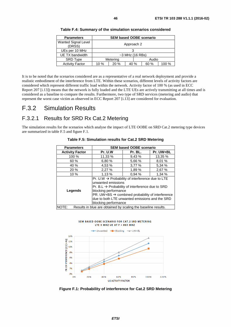
ETSI
ETSI TR 103 288 V1.1.1 (2016-02) 46
Table F.4: Summary of the simulation scenarios considered
Parameters SEM based OOBE scenario Wanted Signal Level
(DRSS) Approach 2
UEs per 10 MHz 3 UE TX bandwidth ~3 MHz (16 RBs)
SRD Type Metering Audio Activity Factor 10 % 20 % 40 % 60 % 100 %
It is to be noted that the scenarios considered are as a representative of a real network deployment and provide a realistic embodiment of the interference from LTE. Within these scenarios, different levels of activity factors are considered which represent different traffic load within the network. Activity factor of 100 % (as used in ECC Report 207 [i.13]) means that the network is fully loaded and the LTE UEs are actively transmitting at all times and is considered as a baseline to compare the results. Furthermore, two type of SRD services (metering and audio) that represent the worst case victim as observed in ECC Report 207 [i.13] are considered for evaluation.
F.3.2 Simulation Results
F.3.2.1 Results for SRD Rx Cat.2 Metering
The simulation results for the scenarios which analyse the impact of LTE OOBE on SRD Cat.2 metering type devices are summarized in table F.5 and figure F.1.
Table F.5: Simulation results for Cat.2 SRD Metering
Parameters SEM based OOBE scenario Activity Factor Pr. U.W Pr. BL. Pr. UW+BL
100 % 11,33 % 9,43 % 13,35 % 60 % 6,80 % 5,66 % 8,01 % 40 % 4,53 % 3,77 % 5,34 % 20 % 2,27 % 1,89 % 2,67 % 10 % 1,13 % 0,94 % 1,34 %
Legends
Pr. U.W � Probability of interference due to LTE unwanted emissions Pr. B.L � Probability of interference due to SRD blocking performance PR. UW+BS � combined probability of interference due to both LTE unwanted emissions and the SRD blocking performance
NOTE: Results in blue are obtained by scaling the baseline results.
Figure F.1: Probability of interference for Cat.2 SRD Metering
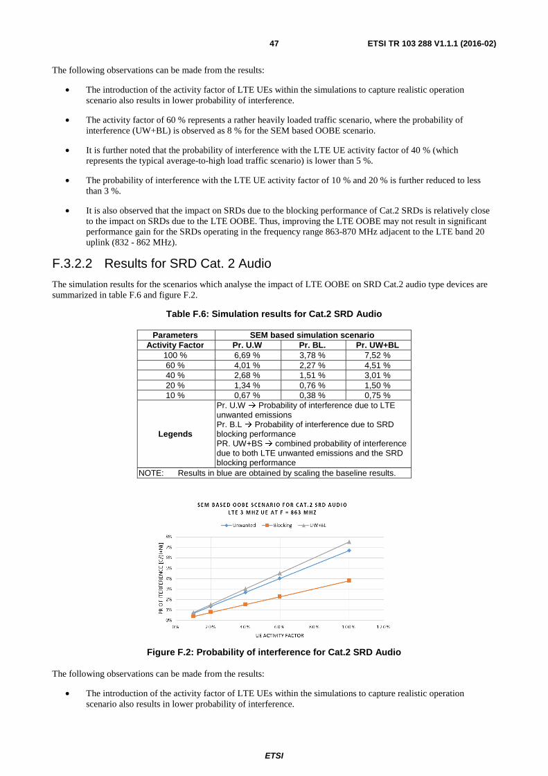
ETSI
ETSI TR 103 288 V1.1.1 (2016-02) 47
The following observations can be made from the results:
• The introduction of the activity factor of LTE UEs within the simulations to capture realistic operation scenario also results in lower probability of interference.
• The activity factor of 60 % represents a rather heavily loaded traffic scenario, where the probability of interference (UW+BL) is observed as 8 % for the SEM based OOBE scenario.
• It is further noted that the probability of interference with the LTE UE activity factor of 40 % (which represents the typical average-to-high load traffic scenario) is lower than 5 %.
• The probability of interference with the LTE UE activity factor of 10 % and 20 % is further reduced to less than 3 %.
• It is also observed that the impact on SRDs due to the blocking performance of Cat.2 SRDs is relatively close to the impact on SRDs due to the LTE OOBE. Thus, improving the LTE OOBE may not result in significant performance gain for the SRDs operating in the frequency range 863-870 MHz adjacent to the LTE band 20 uplink (832 - 862 MHz).
F.3.2.2 Results for SRD Cat. 2 Audio
The simulation results for the scenarios which analyse the impact of LTE OOBE on SRD Cat.2 audio type devices are summarized in table F.6 and figure F.2.
Table F.6: Simulation results for Cat.2 SRD Audio
Parameters SEM based simulation scenario Activity Factor Pr. U.W Pr. BL. Pr. UW+BL
100 % 6,69 % 3,78 % 7,52 % 60 % 4,01 % 2,27 % 4,51 % 40 % 2,68 % 1,51 % 3,01 % 20 % 1,34 % 0,76 % 1,50 % 10 % 0,67 % 0,38 % 0,75 %
Legends
Pr. U.W � Probability of interference due to LTE unwanted emissions Pr. B.L � Probability of interference due to SRD blocking performance PR. UW+BS � combined probability of interference due to both LTE unwanted emissions and the SRD blocking performance
NOTE: Results in blue are obtained by scaling the baseline results.
Figure F.2: Probability of interference for Cat.2 SRD Audio
The following observations can be made from the results:
• The introduction of the activity factor of LTE UEs within the simulations to capture realistic operation scenario also results in lower probability of interference.
ETSI
ETSI TR 103 288 V1.1.1 (2016-02) 48
• In general, the performance impact on the Cat.2 SRD audio devices is much lower than that on the Cat.2 SRD metering devices.
• The activity factor of 60 % represents a rather heavily loaded traffic scenario, where the probability of interference (UW+BL) is observed as 4,51 % for the SEM based OOBE scenario.
F.4 Conclusions & Summary on the impact from LTE on SRD from the additional simulation
F.4.1 Summary of Observations on Simulation Assumptions and Methodology
The analysis in clause F.4 of the present document reviewed the simulation assumptions, methodology and the results presented in ECC Report 207 [i.13] regarding the co-existence of LTE with SRDs within the 800 MHz band. It was noted that the simulation assumptions in ECC Report 207 lead to pessimistic results. Furthermore, additional simulation scenarios were considered to complement the observations made in ECC Report 207 [i.13] and provide a more realistic embodiment of the LTE and SRDs co-existence within the 800 MHz band.
The following major observations were made on the simulation assumptions and methodology.
F.5 Simulation modelling of LTE UE's TX power distribution in 832 - 862 MHz adjacent to SRDs (863 - 870 MHz)
F.5.1 TRP Measurement In TRP measurement, UE is transmitting at maximum power level (+23 dBm) in anechoic chamber. Radiated power is measured from all directions and integrated to find out total radiated power. In addition to free space test condition, there is head and hand use case for simulating speaking position. Browsing test case for smart phones is also under discussion, but measurement results are not yet widely available.
Figure F.3: TRP test set up in an anechoic chamber
The results in table F.7 are measured from 11 commercially available LTE UEs using free space and head & hand conditions according to 3GPP OTA standards (ETSI TS 134 114 [i.48]). Average head and hand loss is 9,1 dB.
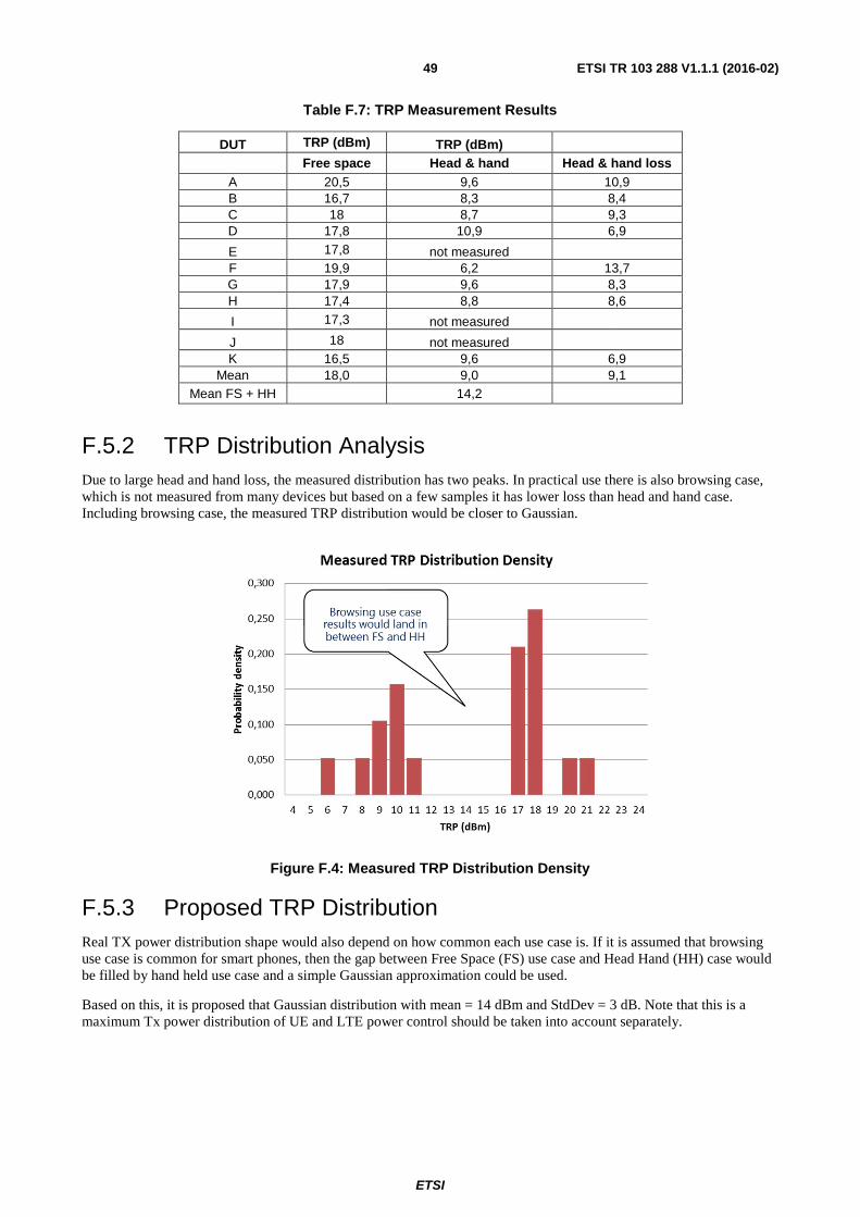
ETSI
ETSI TR 103 288 V1.1.1 (2016-02) 49
Table F.7: TRP Measurement Results
DUT TRP (dBm) TRP (dBm)
Free space Head & hand Head & hand loss A 20,5 9,6 10,9 B 16,7 8,3 8,4 C 18 8,7 9,3 D 17,8 10,9 6,9
E 17,8 not measured
F 19,9 6,2 13,7 G 17,9 9,6 8,3 H 17,4 8,8 8,6
I 17,3 not measured
J 18 not measured
K 16,5 9,6 6,9 Mean 18,0 9,0 9,1
Mean FS + HH
14,2
F.5.2 TRP Distribution Analysis Due to large head and hand loss, the measured distribution has two peaks. In practical use there is also browsing case, which is not measured from many devices but based on a few samples it has lower loss than head and hand case. Including browsing case, the measured TRP distribution would be closer to Gaussian.
Figure F.4: Measured TRP Distribution Density
F.5.3 Proposed TRP Distribution Real TX power distribution shape would also depend on how common each use case is. If it is assumed that browsing use case is common for smart phones, then the gap between Free Space (FS) use case and Head Hand (HH) case would be filled by hand held use case and a simple Gaussian approximation could be used.
Based on this, it is proposed that Gaussian distribution with mean = 14 dBm and StdDev = 3 dB. Note that this is a maximum Tx power distribution of UE and LTE power control should be taken into account separately.
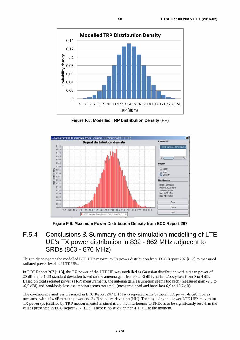
ETSI
ETSI TR 103 288 V1.1.1 (2016-02) 50
Figure F.5: Modelled TRP Distribution Density (HH)
Figure F.6: Maximum Power Distribution Density from ECC Report 207
F.5.4 Conclusions & Summary on the simulation modelling of LTE UE's TX power distribution in 832 - 862 MHz adjacent to SRDs (863 - 870 MHz)
This study compares the modelled LTE UE's maximum Tx power distribution from ECC Report 207 [i.13] to measured radiated power levels of LTE UEs.
In ECC Report 207 [i.13], the TX power of the LTE UE was modelled as Gaussian distribution with a mean power of 20 dBm and 1 dB standard deviation based on the antenna gain from 0 to -3 dBi and hand/body loss from 0 to 4 dB. Based on total radiated power (TRP) measurements, the antenna gain assumption seems too high (measured gain -2,5 to -6,5 dBi) and hand/body loss assumption seems too small (measured head and hand loss 6,9 to 13,7 dB).
The co-existence analysis presented in ECC Report 207 [i.13] was repeated with Gaussian TX power distribution as measured with +14 dBm mean power and 3 dB standard deviation (HH). Then by using this lower LTE UE's maximum TX power (as justified by TRP measurements) in simulation, the interference to SRDs is to be significantly less than the values presented in ECC Report 207 [i.13]. There is no study on non-HH UE at the moment.

ETSI
ETSI TR 103 288 V1.1.1 (2016-02) 51
F.6 Results based on TRP modelling and an improvement of the LTE UE spectrum emission mask by 3 dB
The present clause shows the additional simulation results for new scenarios with two additional simulation assumptions as described below:
• TRP modelling as suggested in clause X.6, i.e. the LTE UE's transmit power is modelled by a Gaussian distribution with +14 dBm mean power and 3 dB standard deviation;
• A 3 dB tighter spectrum emission mask for LTE UE, i.e. 3 dB improvement of spectrum emission mask compared to that defined in ETSI TS 136 101 [i.28].
Results are based on measurements using free space and head & hand conditions according to 3GPP OTA standards (ETSI TS 134 114 [i.48]).
Table F.8 provides a summary of simulation scenarios considered for evaluation.
Table F.8: Summary of the simulation scenarios considered
The simulation results for the scenarios analysed are presented in tables F.9 and F.10.
Table F.9: Results for SRD Cat. 2 Audio
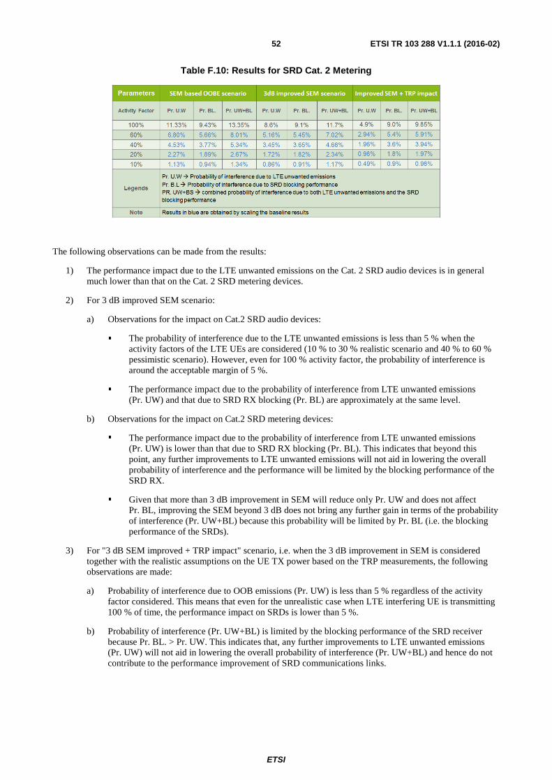
ETSI
ETSI TR 103 288 V1.1.1 (2016-02) 52
Table F.10: Results for SRD Cat. 2 Metering
The following observations can be made from the results:
1) The performance impact due to the LTE unwanted emissions on the Cat. 2 SRD audio devices is in general much lower than that on the Cat. 2 SRD metering devices.
2) For 3 dB improved SEM scenario:
a) Observations for the impact on Cat.2 SRD audio devices:
� The probability of interference due to the LTE unwanted emissions is less than 5 % when the activity factors of the LTE UEs are considered (10 % to 30 % realistic scenario and 40 % to 60 % pessimistic scenario). However, even for 100 % activity factor, the probability of interference is around the acceptable margin of 5 %.
� The performance impact due to the probability of interference from LTE unwanted emissions (Pr. UW) and that due to SRD RX blocking (Pr. BL) are approximately at the same level.
b) Observations for the impact on Cat.2 SRD metering devices:
� The performance impact due to the probability of interference from LTE unwanted emissions (Pr. UW) is lower than that due to SRD RX blocking (Pr. BL). This indicates that beyond this point, any further improvements to LTE unwanted emissions will not aid in lowering the overall probability of interference and the performance will be limited by the blocking performance of the SRD RX.
� Given that more than 3 dB improvement in SEM will reduce only Pr. UW and does not affect Pr. BL, improving the SEM beyond 3 dB does not bring any further gain in terms of the probability of interference (Pr. UW+BL) because this probability will be limited by Pr. BL (i.e. the blocking performance of the SRDs).
3) For "3 dB SEM improved + TRP impact" scenario, i.e. when the 3 dB improvement in SEM is considered together with the realistic assumptions on the UE TX power based on the TRP measurements, the following observations are made:
a) Probability of interference due to OOB emissions (Pr. UW) is less than 5 % regardless of the activity factor considered. This means that even for the unrealistic case when LTE interfering UE is transmitting 100 % of time, the performance impact on SRDs is lower than 5 %.
b) Probability of interference (Pr. UW+BL) is limited by the blocking performance of the SRD receiver because Pr. BL. > Pr. UW. This indicates that, any further improvements to LTE unwanted emissions (Pr. UW) will not aid in lowering the overall probability of interference (Pr. UW+BL) and hence do not contribute to the performance improvement of SRD communications links.
ETSI
ETSI TR 103 288 V1.1.1 (2016-02) 53
F.7 Proposal The results presented in clause F.4 show that if a more realistic assumptions are taken into account for the operation of LTE networks in the 800 MHz band, the SRD devices will not face significant interference from the LTE UE OOB emissions. These assumptions lead to a probability of interference of less than 5 % to the SRDs and to the fact that the impact on SRDs receivers due to the LTE OOB emissions is close to the impact on SRDs receivers due to their blocking performance (see the results in tables F.5 and F.6 for "SEM based OOBE scenario").
Results presented in annex F demonstrate that LTE will provide sufficient protection to the SRDs with an improvement of SEM by 3 dB. Additionally, considering this SEM improvement together with the impacts of TRP indicates that the probability of interference from LTE unwanted emissions is very low. As pointed out in clause F.7, an improvement of the SEM beyond 3 dB does not bring any further gain in terms of the probability of interference (Pr. UW+BL) and therefore, any further improvement in SRD link performance will depend on the SRDs receiver blocking. As a result, a 3 dB improvement of LTE UE spectrum emission mask is proposed in the frequency range 863 - 870 MHz as an additional measure for providing better protection to SRDs as requested by the European Commission.
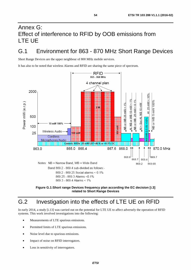
ETSI
ETSI TR 103 288 V1.1.1 (2016-02) 54
Annex G: Effect of interference to RFID by OOB emissions from LTE UE
G.1 Environment for 863 - 870 MHz Short Range Devices Short Range Devices are the upper neighbour of 800 MHz mobile services.
It has also to be noted that wireless Alarms and RFID are sharing the same piece of spectrum.
Figure G.1:Short range Devices frequency plan according the EC decision [i.3] related to Short Range Devices
G.2 Investigation into the effects of LTE UE on RFID In early 2014, a study [i.13] was carried out on the potential for LTE UE to affect adversely the operation of RFID systems. This work involved investigations into the following:
• Measurements of LTE spurious emissions.
• Permitted limits of LTE spurious emissions.
• Noise level due to spurious emissions.
• Impact of noise on RFID interrogators.
• Loss in sensitivity of interrogators.
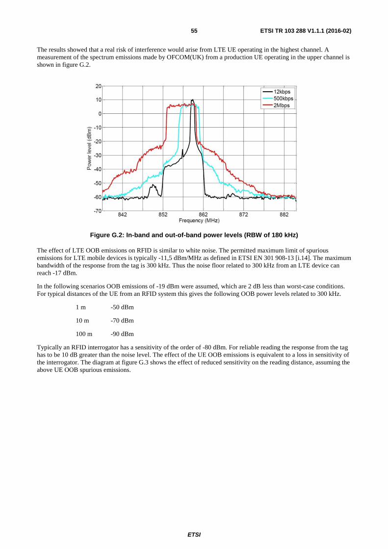
ETSI
ETSI TR 103 288 V1.1.1 (2016-02) 55
The results showed that a real risk of interference would arise from LTE UE operating in the highest channel. A measurement of the spectrum emissions made by OFCOM(UK) from a production UE operating in the upper channel is shown in figure G.2.
Figure G.2: In-band and out-of-band power levels (RBW of 180 kHz)
The effect of LTE OOB emissions on RFID is similar to white noise. The permitted maximum limit of spurious emissions for LTE mobile devices is typically -11,5 dBm/MHz as defined in ETSI EN 301 908-13 [i.14]. The maximum bandwidth of the response from the tag is 300 kHz. Thus the noise floor related to 300 kHz from an LTE device can reach -17 dBm.
In the following scenarios OOB emissions of -19 dBm were assumed, which are 2 dB less than worst-case conditions. For typical distances of the UE from an RFID system this gives the following OOB power levels related to 300 kHz.
1 m -50 dBm
10 m -70 dBm
100 m -90 dBm
Typically an RFID interrogator has a sensitivity of the order of -80 dBm. For reliable reading the response from the tag has to be 10 dB greater than the noise level. The effect of the UE OOB emissions is equivalent to a loss in sensitivity of the interrogator. The diagram at figure G.3 shows the effect of reduced sensitivity on the reading distance, assuming the above UE OOB spurious emissions.
ETSI
ETSI TR 103 288 V1.1.1 (2016-02) 56
Figure G.3: Loss in sensitivity loss of interrogator due to LTE OOB emissions
Figure G.4 is illustrative of the improvement that could be achieved in the reading performance of RFID systems if the LTE OOB spurious emissions could be reduced.
Figure G.4: Improvement possible with a reduction in LTE OOB emissions
These results were validated by practical measurements made on interrogators supplied by 2 different RFID manufactures. Their results confirmed that OOB emissions by LTE UE above a certain level could be detrimental to the satisfactory operation of RFID.
ETSI
ETSI TR 103 288 V1.1.1 (2016-02) 57
Annex H: Wireless broadband relevant to PMR systems
H.1 Description of LTE Signals At present there are no wireless broadband systems that operate in or adjacent to, spectrum adjacent to PMR systems however in the future it is foreseen that broadband systems may operate in adjacent spectrum to PMR systems e.g. the VHF band (174 -230 MHz). It may also be that broad systems operate down to the boundary PMR spectrum at 470 MHz.
PMR already supports data systems with channels up to 150 kHz [i.6]. Broadband data systems of greater than 150 kHz are not presently envisaged in PMR spectrum.
The most likely source of broadband interference is the LTE system [i.13]. The following test signals are specified within the LTE standard:
• E-TM1.1: QPSK, no power variation within 20 MHz bandwidth, uses all RB.
• E-TM1.2: QPSK, not all RB used, power variation in 20 MHz bandwidth: 40 %: + 3 dB, 60 % - 4,73 dB; test signal used for ACLR and operating band unwanted emissions.
• E-TM2: 64QAM (1 %), 99 % off; maximum dynamic range; replicates "Idle Mode".
• E-TM3.1: 64QAM, All RB used, no power variation at 20 MHz bandwidth.
• E-TM3.2: 16QAM (60 %), QPSK (40 %), used for testing transmitted signal quality, EVM, frequency error.
Following plots (figure H.1 to figure H.6) show spectra of each signal with separate traces for average power (rms detector), clear write (sample detector) and peak hold (positive peak detector). The LTE is generated in each case by a SMBV-100a signal generator.
Figure H.1: E-TM1.1 signal, -33 dBm mean power
ETSI
ETSI TR 103 288 V1.1.1 (2016-02) 58
Figure H.2: E-TM1.2 signal, -33 dBm mean power
Figure H.3: E-TM2 signal ("idle mode"), -33 dBm mean power, Slow sweep
ETSI
ETSI TR 103 288 V1.1.1 (2016-02) 59
Figure H.4: E-TM2 signal ("idle mode"), fast sweep
Figure H.5: E-TM3.1 signal, -33 dBm mean power
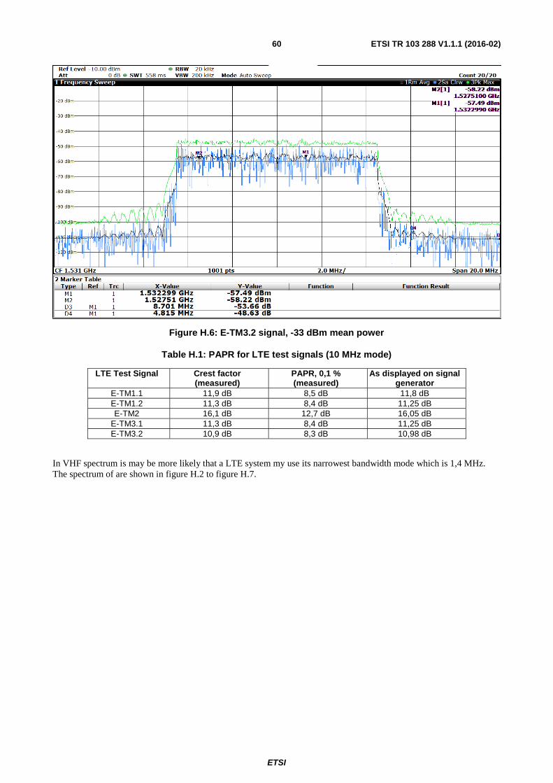
ETSI
ETSI TR 103 288 V1.1.1 (2016-02) 60
Figure H.6: E-TM3.2 signal, -33 dBm mean power
Table H.1: PAPR for LTE test signals (10 MHz mode)
LTE Test Signal Crest factor (measured)
PAPR, 0,1 % (measured)
As displayed on signal generator
E-TM1.1 11,9 dB 8,5 dB 11,8 dB E-TM1.2 11,3 dB 8,4 dB 11,25 dB E-TM2 16,1 dB 12,7 dB 16,05 dB
E-TM3.1 11,3 dB 8,4 dB 11,25 dB E-TM3.2 10,9 dB 8,3 dB 10,98 dB
In VHF spectrum is may be more likely that a LTE system my use its narrowest bandwidth mode which is 1,4 MHz. The spectrum of are shown in figure H.2 to figure H.7.
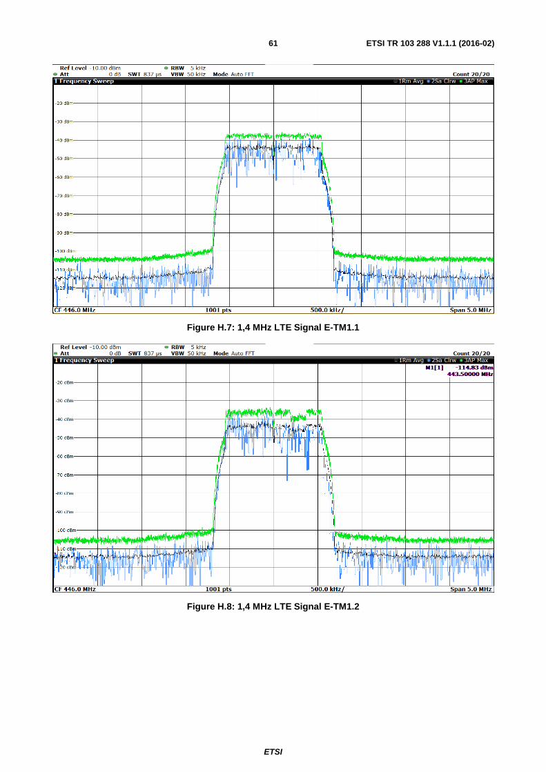
ETSI
ETSI TR 103 288 V1.1.1 (2016-02) 61
Figure H.7: 1,4 MHz LTE Signal E-TM1.1
Figure H.8: 1,4 MHz LTE Signal E-TM1.2
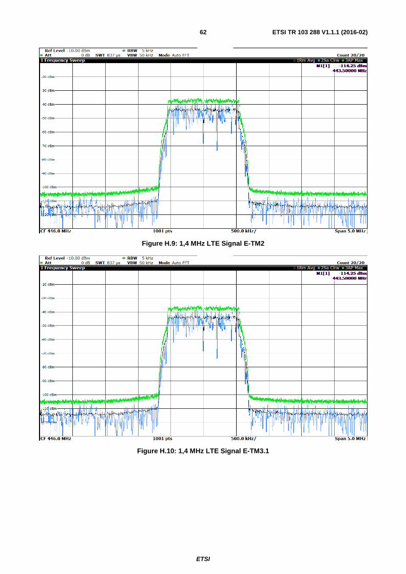
ETSI
ETSI TR 103 288 V1.1.1 (2016-02) 62
Figure H.9: 1,4 MHz LTE Signal E-TM2
Figure H.10: 1,4 MHz LTE Signal E-TM3.1
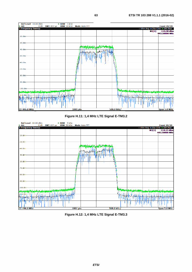
ETSI
ETSI TR 103 288 V1.1.1 (2016-02) 63
Figure H.11: 1,4 MHz LTE Signal E-TM3.2
Figure H.12: 1,4 MHz LTE Signal E-TM3.3
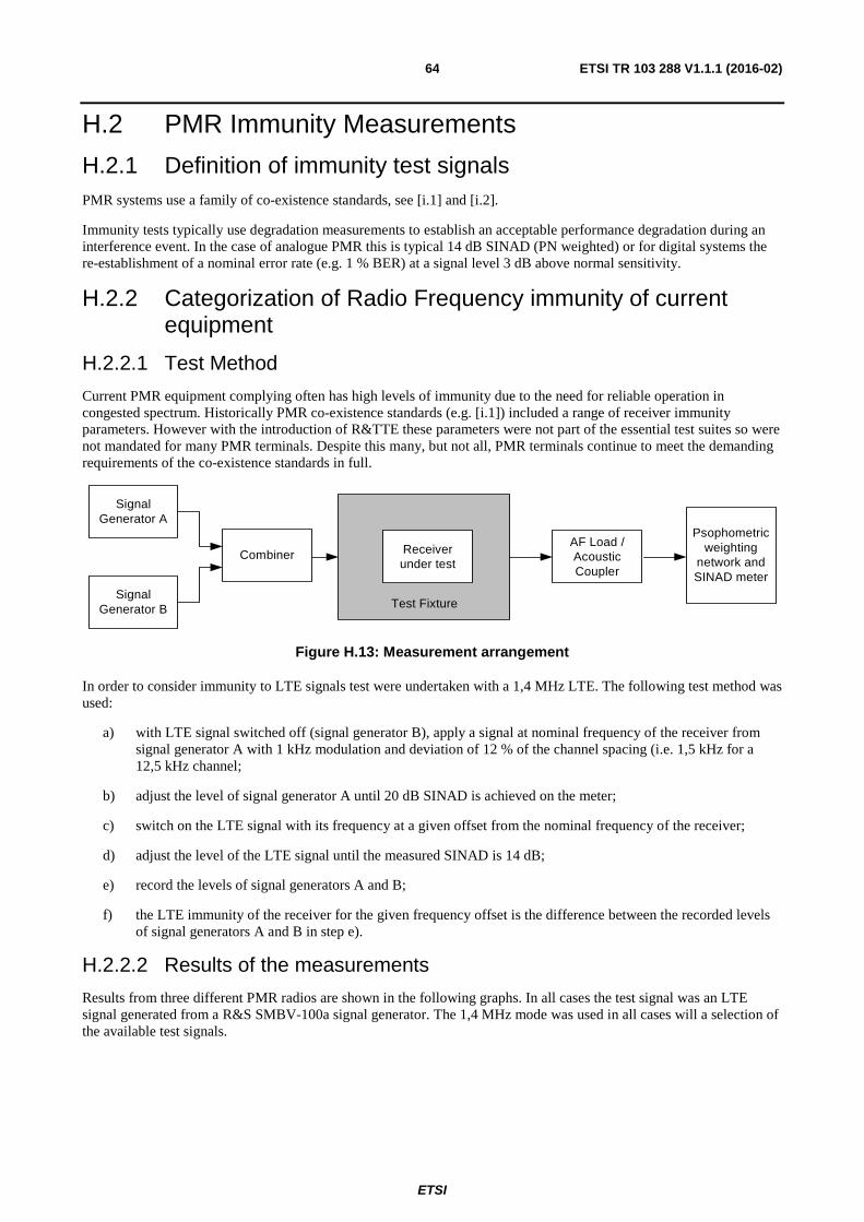
ETSI
ETSI TR 103 288 V1.1.1 (2016-02) 64
H.2 PMR Immunity Measurements
H.2.1 Definition of immunity test signals PMR systems use a family of co-existence standards, see [i.1] and [i.2].
Immunity tests typically use degradation measurements to establish an acceptable performance degradation during an interference event. In the case of analogue PMR this is typical 14 dB SINAD (PN weighted) or for digital systems the re-establishment of a nominal error rate (e.g. 1 % BER) at a signal level 3 dB above normal sensitivity.
H.2.2 Categorization of Radio Frequency immunity of current equipment
H.2.2.1 Test Method
Current PMR equipment complying often has high levels of immunity due to the need for reliable operation in congested spectrum. Historically PMR co-existence standards (e.g. [i.1]) included a range of receiver immunity parameters. However with the introduction of R&TTE these parameters were not part of the essential test suites so were not mandated for many PMR terminals. Despite this many, but not all, PMR terminals continue to meet the demanding requirements of the co-existence standards in full.
AF Load / Acoustic Coupler
Receiver under test
Psophometric weighting
network and SINAD meter
Test Fixture
Combiner
Signal Generator A
Signal Generator B
Figure H.13: Measurement arrangement
In order to consider immunity to LTE signals test were undertaken with a 1,4 MHz LTE. The following test method was used:
a) with LTE signal switched off (signal generator B), apply a signal at nominal frequency of the receiver from signal generator A with 1 kHz modulation and deviation of 12 % of the channel spacing (i.e. 1,5 kHz for a 12,5 kHz channel;
b) adjust the level of signal generator A until 20 dB SINAD is achieved on the meter;
c) switch on the LTE signal with its frequency at a given offset from the nominal frequency of the receiver;
d) adjust the level of the LTE signal until the measured SINAD is 14 dB;
e) record the levels of signal generators A and B;
f) the LTE immunity of the receiver for the given frequency offset is the difference between the recorded levels of signal generators A and B in step e).
H.2.2.2 Results of the measurements
Results from three different PMR radios are shown in the following graphs. In all cases the test signal was an LTE signal generated from a R&S SMBV-100a signal generator. The 1,4 MHz mode was used in all cases will a selection of the available test signals.
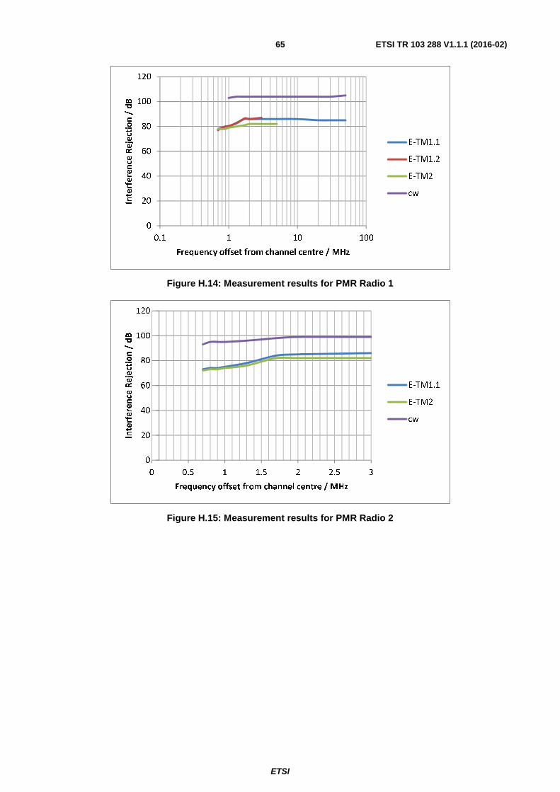
ETSI
ETSI TR 103 288 V1.1.1 (2016-02) 65
Figure H.14: Measurement results for PMR Radio 1
Figure H.15: Measurement results for PMR Radio 2
0
20
40
60
80
100
120
0.1 1 10 100
Interference Rejection / dB
Frequency offset from channel centre / MHz
E-TM1.1
E-TM1.2
E-TM2
cw
0
20
40
60
80
100
120
0 0.5 1 1.5 2 2.5 3
Interference Rejection / dB
Frequency offset from channel centre / MHz
E-TM1.1
E-TM2
cw
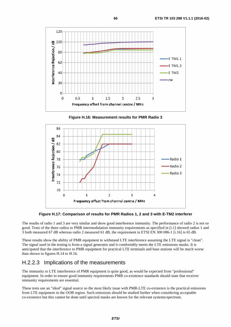
ETSI
ETSI TR 103 288 V1.1.1 (2016-02) 66
Figure H.16: Measurement results for PMR Radio 3
Figure H.17: Comparison of results for PMR Radios 1, 2 and 3 with E-TM2 interferer
The results of radio 1 and 3 are very similar and show good interference immunity. The performance of radio 2 is not so good. Tests of the three radios to PMR intermodulation immunity requirements as specified in [i.1] showed radios 1 and 3 both measured 67 dB whereas radio 2 measured 61 dB, the requirement in ETSI EN 300 086-1 [i.16] is 65 dB.
These results show the ability of PMR equipment to withstand LTE interference assuming the LTE signal is "clean". The signal used in the testing is from a signal generator and it comfortably meets the LTE emissions masks. It is anticipated that the interference to PMR equipment for practical LTE terminals and base stations will be much worse than shown in figures H.14 to H.16.
H.2.2.3 Implications of the measurements
The immunity to LTE interference of PMR equipment is quite good, as would be expected from "professional" equipment. In order to ensure good immunity requirements PMR co-existence standards should state that receiver immunity requirements are essential.
These tests use an "ideal" signal source so the most likely issue with PMR-LTE co-existence is the practical emissions from LTE equipment in the OOB region. Such emissions should be studied further when considering acceptable co-existence but this cannot be done until spectral masks are known for the relevant systems/spectrum.
0
20
40
60
80
100
120
0 0.5 1 1.5 2 2.5 3
Interference Rejection / dB
Frequency offset from channel centre / MHz
E-TM1.1
E-TM1.2
E-TM2
cw
70
72
74
76
78
80
82
84
86
0 1 2 3 4
Interference Rejection / dB
Frequency offset from channel centre / MHz
Radio 1
Radio 2
Radio 3
ETSI
ETSI TR 103 288 V1.1.1 (2016-02) 67
Annex I: Detailed information on PMSE and ALDs Programme Making includes the making of a programme for broadcast, the making of a film, presentation, advertisement or audio or video recordings, and the staging or performance of an entertainment, sporting or other public event.
A Special Events is an occurrence of limited duration, typically between one day and a few weeks, which take place on specifically defined locations. Examples include large cultural, sport, entertainment, religious and other festivals, conferences and trade fairs. In the entertainment industry, theatrical productions may run for considerably longer.
Radio microphones (see figure I.1) are either handheld or body worn microphones with integrated or body worn transmitter. They transmit the audio from the user to a remote receiver and then into audio amplification or the broadcast receiver.
Figure I.1: Radio Microphones
In-Ear Monitors (IEM), see figure I.2, are body-worn miniature receivers with earpieces for personal monitoring of single or dual (stereo) channel sound track. These are similar in appearance to the body worn radio microphone shown above. They were developed to prevent damage to the user's hearing from very loud speakers (referred to as fold back speakers) which were used previously to covey the total mix of music to the singer in order that they could sing in tune.
They are used for both the music function and also for conveying instructions to the user.
A transmitter located at the back of a stage takes the combined audio from all the other singers and instruments and transmits to the IEM.
Figure I.2: In-Ear Monitors
ALDs are medical devices which are fitted to children as young as six weeks, which enables the child to receive the same input and simulation as a child with normal hearing. ALDs are used within schools and educational establishments.
ALDs in their various forms will be used by up to 55 % [i.13] of adults at some point. Figure I.3 provides an overview of a common use case.
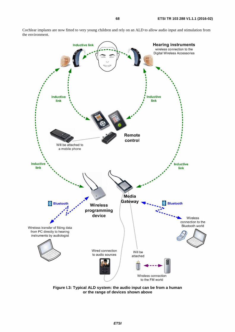
ETSI
ETSI TR 103 288 V1.1.1 (2016-02) 68
Cochlear implants are now fitted to very young children and rely on an ALD to allow audio input and stimulation from the environment.
Figure I.3: Typical ALD system: the audio input can be from a human or the range of devices shown above
ETSI
ETSI TR 103 288 V1.1.1 (2016-02) 69
Annex J: Change History
Date Version Information about changes
October 2011 1.1.1 First publication of the TS after approval by TC SPAN at SPAN#19 (30 September - 2 October 2011; Prague).
February 2012 1.2.1
Implemented Change Requests: SPAN(12)20_019 Error message information clarifications SPAN(12)20_033 Revised error message information SPAN(12)20_046 update of figure 3 clause 9.2 These CRs were approved by TC SPAN#20 (3 - 5 February 2012; Sophia) Version 1.2.1 prepared by the Rapporteur.
July 2013 1.3.1
Implemented Changes: Correction needed because the previously approved version did not contain the last version of the ASN.1 and XML attachments. Version 1.3.1 prepared by the Rapporteur.
ETSI
ETSI TR 103 288 V1.1.1 (2016-02) 70
History
Document history
V1.1.1 February 2016 Publication


![EN 303 316 - V1.1.1 - Broadband Direct Air-to-Ground … · 2017. 10. 6. · Report 209 [i.1] (for the 1 900 MHz to 1 920 MHz band) and ECC Report 210 [i.2] (for the 5 855 MHz to](https://img.pdfslide.us/doc/110x75/603f5b2b87f6a63a62176250/en-303-316-v111-broadband-direct-air-to-ground-2017-10-6-report-209-i1.jpg)