Embed Size (px)
Citation preview

ETSI TR 103 122 V1.1.1 (2012-11)
Speech and multimedia Transmission Quality (STQ); QoS of connections from current technologies to LTE
for delay sensitive applications
Technical Report
ETSI
ETSI TR 103 122 V1.1.1 (2012-11) 2
Reference DTR/STQ-193
Keywords interoperability, LTE, QoS
ETSI
650 Route des Lucioles F-06921 Sophia Antipolis Cedex - FRANCE
Tel.: +33 4 92 94 42 00 Fax: +33 4 93 65 47 16
Siret N° 348 623 562 00017 - NAF 742 C
Association à but non lucratif enregistrée à la Sous-Préfecture de Grasse (06) N° 7803/88
Important notice
Individual copies of the present document can be downloaded from: http://www.etsi.org
The present document may be made available in more than one electronic version or in print. In any case of existing or perceived difference in contents between such versions, the reference version is the Portable Document Format (PDF).
In case of dispute, the reference shall be the printing on ETSI printers of the PDF version kept on a specific network drive within ETSI Secretariat.
Users of the present document should be aware that the document may be subject to revision or change of status. Information on the current status of this and other ETSI documents is available at
http://portal.etsi.org/tb/status/status.asp
If you find errors in the present document, please send your comment to one of the following services: http://portal.etsi.org/chaircor/ETSI_support.asp
Copyright Notification
No part may be reproduced except as authorized by written permission. The copyright and the foregoing restriction extend to reproduction in all media.
© European Telecommunications Standards Institute 2012.
All rights reserved.
DECTTM, PLUGTESTSTM, UMTSTM and the ETSI logo are Trade Marks of ETSI registered for the benefit of its Members. 3GPPTM and LTE™ are Trade Marks of ETSI registered for the benefit of its Members and
of the 3GPP Organizational Partners. GSM® and the GSM logo are Trade Marks registered and owned by the GSM Association.
ETSI
ETSI TR 103 122 V1.1.1 (2012-11) 3
Contents
Intellectual Property Rights ................................................................................................................................ 5
Foreword ............................................................................................................................................................. 5
Introduction ........................................................................................................................................................ 5
1 Scope ........................................................................................................................................................ 6
2 References ................................................................................................................................................ 6
2.1 Normative references ......................................................................................................................................... 6
2.2 Informative references ........................................................................................................................................ 6
3 Abbreviations ........................................................................................................................................... 9
4 Addressing LTE related QoS problems for delay sensitive applications ............................................... 12
4.1 Determination of e2e QoS scenarios ................................................................................................................ 12
4.2 General considerations ..................................................................................................................................... 14
4.2.1 Jitter Buffer Problems ................................................................................................................................. 14
4.2.2 Handover .................................................................................................................................................... 15
4.2.3 Codec Issues ............................................................................................................................................... 15
4.2.4 V.152 and T.38 transmissions ..................................................................................................................... 16
4.2.5 DTMF ......................................................................................................................................................... 16
4.2.6 Resource Allocation .................................................................................................................................... 17
4.2.7 Delay Budgets ............................................................................................................................................. 18
4.2.8 Discontinuous Reception (DRX) ................................................................................................................ 18
4.2.9 Characteristics of LTE media quality ......................................................................................................... 19
4.3 Relations to other radio-link technologies (mainly UMTS) ............................................................................. 19
4.3.1 Load of the network .................................................................................................................................... 19
4.3.2 Delay ........................................................................................................................................................... 20
4.3.3 Drawback of IPv6 usage ............................................................................................................................. 20
4.4 QoS problems encountered by operators .......................................................................................................... 20
5 Overview of shortcomings, identified .................................................................................................... 22
5.1 Shortcomings of Standards, Overview ............................................................................................................. 22
5.2 Shortcomings of Implementations, Overview .................................................................................................. 23
5.3 Comparison of shortcomings of standards and implementations with other radio-link technologies (mainly UMTS) ................................................................................................................................................ 25
6 Detailed Review of Standards dealing with IMS Multimedia Telephony and IMS Profiles and Resource and Admission Control Architectures .................................................................................... 25
6.1 Review of Standards dealing IMS Multimedia Telephony and IMS Profiles for Voice, SMS and Conversational Video Service .......................................................................................................................... 25
6.1.1 Detailed Review of 3GPP Standard dealing with IMS Multimedia Telephony .......................................... 26
6.1.2 Detailed Review of GSMA Permanent Reference Document describing IMS profiles for voice and SMS ............................................................................................................................................................ 27
6.1.3 Detailed Review of GSMA Permanent Reference Document describing IMS profile for Conversational Video Service..................................................................................................................... 28
6.1.4 Detailed Review of TS 126 131 dealing with Terminal Acoustics Characteristics for Telephony ............. 28
6.2 Review of Standards dealing with Resource and Admission Control Architectures ........................................ 28
6.2.1 Functional comparison of Resource and Admission Architectures defined by ETSI TC TISPAN and 3GPP ........................................................................................................................................................... 29
6.2.2 Comparison of Interfaces and Procedures of Resource and Admission Architectures defined by ETSI TC TISPAN and 3GPP ............................................................................................................................... 31
6.2.2.1 Comparison of Interfaces of Resource and Admission Architectures defined by ETSI TC TISPAN and 3GPP ................................................................................................................................ 31
6.2.2.2 Comparison of Initial Admission and Reservation Procedures of Resource and Admission Architectures defined by ETSI TC TISPAN and 3GPP ........................................................................ 32
6.2.2.3 Comparison of Modification Procedures of Resource and Admission Architectures defined by ETSI TC TISPAN and 3GPP ................................................................................................................ 32

ETSI
ETSI TR 103 122 V1.1.1 (2012-11) 4
6.2.2.4 Comparison of Termination Procedures of Resource and Admission Architectures defined by ETSI TC TISPAN and 3GPP ................................................................................................................ 32
7 Detailed Description of Shortcomings of Implementations ................................................................... 32
7.1 Interim Solutions .............................................................................................................................................. 32
7.2 Migration of Voice Service to LTE .................................................................................................................. 33
7.3 VoLTE Interop Testing .................................................................................................................................... 34
7.3.1 Description of Scenarios: ............................................................................................................................ 34
7.3.2 Selected Results and Issues ......................................................................................................................... 35
7.3.3 Conclusions................................................................................................................................................. 36
8 Possible Solutions .................................................................................................................................. 37
8.1 Actions for Standards ....................................................................................................................................... 37
8.1.1 Codec aspects .............................................................................................................................................. 37
8.1.2 Jitter-buffer Management Mechanisms ...................................................................................................... 38
8.1.3 Quality of Experience metrics .................................................................................................................... 38
8.1.4 Framework for Gq'/Rx harmonization ........................................................................................................ 41
8.2 Actions for Implementations ............................................................................................................................ 41
8.2.1 Migration of voice service to LTE .............................................................................................................. 42
8.2.2 VoLTE Interop testing ................................................................................................................................ 42
8.3 Comparison of the proposed solutions with solutions used for other radio-link technologies (mainly UMTS) ............................................................................................................................................................. 42
9 Concluding remarks ............................................................................................................................... 43
History .............................................................................................................................................................. 44

ETSI
ETSI TR 103 122 V1.1.1 (2012-11) 5
Intellectual Property Rights IPRs essential or potentially essential to the present document may have been declared to ETSI. The information pertaining to these essential IPRs, if any, is publicly available for ETSI members and non-members, and can be found in ETSI SR 000 314: "Intellectual Property Rights (IPRs); Essential, or potentially Essential, IPRs notified to ETSI in respect of ETSI standards", which is available from the ETSI Secretariat. Latest updates are available on the ETSI Web server (http://ipr.etsi.org).
Pursuant to the ETSI IPR Policy, no investigation, including IPR searches, has been carried out by ETSI. No guarantee can be given as to the existence of other IPRs not referenced in ETSI SR 000 314 (or the updates on the ETSI Web server) which are, or may be, or may become, essential to the present document.
Foreword This Technical Report (TR) has been produced by ETSI Technical Committee Speech and multimedia Transmission Quality (STQ).
Introduction One clear focus of the development of LTE is wireless broadband access, i.e. data access, streaming applications etc. However, in order to allow integration with existing technologies, all other major applications, which are currently running on existing technologies should be possible also in an LTE environment.
QoS aspects for connections between existing technologies and LTE, especially delay sensitive applications, such as voice and video telephony need additional consideration.
Voice over LTE requires the implementation of IMS, but since the deployment of IMS on the one hand and LTE on the other hand is driven by completely different motivation factors, several interim solutions have been invented, which all have serious drawbacks.
Since LTE is considered a "mobile technology" in the first place, priority has been given to LTE to support AMR "mobile codecs" only. IMS profiles for other codecs have not been defined yet.
While this is a major obstacle when attempting to interconnect existing technologies with LTE, there are further obstacles in the architectural domain which prevent successful interoperability in such cases.
The standard's community has not paid great attention to these issues yet.

ETSI
ETSI TR 103 122 V1.1.1 (2012-11) 6
1 Scope The present document addresses QoS problems when interconnecting between existing technologies and LTE. The focus is on delay sensitive applications and the determination of possible shortcomings of the existing standards and possible shortcomings of known implementations at the time this report was produced. Furthermore, possible solutions and future work are discussed.
The present document concentrates on delay sensitive applications, such as Voice over LTE (VoLTE) and Video Telephony over LTE (VToLTE) and the QoS associated with their interconnection with existing technologies.
Interim solutions which are only meant to overcome the current lack of availability of IMS in many existing networks, are in most cases not standardized, but the available material is taken into account.
2 References References are either specific (identified by date of publication and/or edition number or version number) or non-specific. For specific references, only the cited version applies. For non-specific references, the latest version of the referenced document (including any amendments) applies.
Referenced documents which are not found to be publicly available in the expected location might be found at http://docbox.etsi.org/Reference.
NOTE: While any hyperlinks included in this clause were valid at the time of publication ETSI cannot guarantee their long term validity.
2.1 Normative references The following referenced documents are necessary for the application of the present document.
Not applicable.
2.2 Informative references The following referenced documents are not necessary for the application of the present document but they assist the user with regard to a particular subject area.
[i.1] 3GPP TR 23.822: "Framework for Gq'/Rx harmonization" (withdrawn, ETSI has not approved any equivalent document).
NOTE: Available at http://www.3gpp.org/ftp/Specs/html-info/23822.htm [online], last accessed 18 September 2012.
[i.2] Balbas, J.-J.P.; Rommer, S.; Stenfelt, J.: "Policy and charging control in the evolved packet system" Communications Magazine, IEEE , vol.47, no.2, pp.68-74, February 2009, doi: 10.1109/MCOM.2009.4785382.
NOTE: Available at http://ieeexplore.ieee.org/stamp/stamp.jsp?tp=&arnumber=4785382&isnumber=4785366
[i.3] Bauer, B., & Patrick, A.S. (2004). "A Human Factors Extension to the Seven-Layer OSI Reference Model".
NOTE: Available at http://www.andrewpatrick.ca/OSI/10layer.html, [online] last accessed 19 September 2010.
[i.4] ETSI ES 201 235-1 (V1.1.1): "Specification of Dual Tone Multi-Frequency (DTMF) Transmitters and Receivers; Part 1: General".
[i.5] ETSI ES 201 235-2 (V1.2.1): "Access and Terminals (AT);Specification of Dual-Tone Multi-Frequency (DTMF) Transmitters and Receivers; Part 2: Transmitters".
ETSI
ETSI TR 103 122 V1.1.1 (2012-11) 7
[i.6] ETSI ES 201 235-3 (V1.3.1): "Access and Terminals (AT);Specification of Dual-Tone Multi-Frequency (DTMF) Transmitters and Receivers; Part 3: Receivers".
[i.7] ETSI ES 201 235-4 (V1.3.1): "Access and Terminals (AT);Specification of Dual-Tone Multi-Frequency (DTMF) Transmitters and Receivers; Part 4: Transmitters and Receivers for use in Terminal Equipment for end-to-end signalling".
[i.8] ETSI ES 282 003 (V3.5.1): "Telecommunications and Internet converged Services and Protocols for Advanced Networking (TISPAN); Resource and Admission Control Sub-System (RACS): Functional Architecture".
[i.9] ETSI TR 121 905 (V10.3.0): "Digital cellular telecommunications system (Phase 2+); Universal Mobile Telecommunications System (UMTS); LTE; Vocabulary for 3GPP Specifications (3GPP TR 21.905 version 10.3.0 Release 10)".
[i.10] ETSI TS 103 737 (V1.1.2): "Speech and multimedia Transmission Quality (STQ);Transmission requirements for narrowband wireless terminals (handset and headset) from a QoS perspective as perceived by the user".
[i.11] ETSI TS 103 738 (V1.1.2): "Speech and multimedia Transmission Quality (STQ);Transmission requirements for narrowband wireless terminals (handsfree) from a QoS perspective as perceived by the user".
[i.12] ETSI TS 103 739 (V1.1.2): "Speech and multimedia Transmission Quality (STQ);Transmission requirements for wideband wireless terminals (handset and headset) from a QoS perspective as perceived by the user".
[i.13] ETSI TS 103 740 (V1.1.2): "Speech and multimedia Transmission Quality (STQ);Transmission requirements for wideband wireless terminals (handsfree) from a QoS perspective as perceived by the user".
[i.14] ETSI TS 123 203 (V10.7.0): "Digital cellular telecommunications system (Phase 2+); Universal Mobile Telecommunications System (UMTS); LTE; Policy and charging control architecture (3GPP TS 23.203 Release 10)".
[i.15] ETSI TS 123 206 (V7.5.0): "Digital cellular telecommunications system (Phase 2+); Universal Mobile Telecommunications System (UMTS); Voice Call Continuity (VCC) between Circuit Switched (CS) and IP Multimedia Subsystem (IMS); Stage 2 (3GPP TS 23.206 Release 7)".
[i.16] ETSI TS 123 216: "Digital cellular telecommunications system (Phase 2+); Universal Mobile Telecommunications System (UMTS); LTE; Single Radio Voice Call Continuity (SRVCC); Stage 2 (3GPP TS 23.216 version 10.4.0 Release 10)".
[i.17] ETSI TS 123 272 (V10.8.0): "Digital cellular telecommunications system (Phase 2+); Universal Mobile Telecommunications System (UMTS); LTE; Circuit Switched (CS) fallback in Evolved Packet System (EPS); Stage 2 (3GPP TS 23.272 Release 10)".
[i.18] ETSI TS 126 073 (V10.0.0): "Digital cellular telecommunications system (Phase 2+); Universal Mobile Telecommunications System (UMTS); LTE; ANSI C code for the Adaptive Multi Rate (AMR) speech codec (3GPP TS 26.073 Release 10)".
[i.19] ETSI TS 126 091 (V10.0.0): "Digital cellular telecommunications system (Phase 2+); Universal Mobile Telecommunications System (UMTS); LTE; Mandatory Speech Codec speech processing functions; Adaptive Multi-Rate (AMR) speech codec; Error concealment of lost frames (3GPP TS 26.091 Release 10)".
[i.20] ETSI TS 126 114 (V10.4.0): "Universal Mobile Telecommunications System (UMTS); LTE; IP Multimedia Subsystem (IMS); Multimedia telephony; Media handling and interaction (3GPP TS 26.114 Release 10)".
[i.21] ETSI TS 126 131 (V 10.4.0): "Universal Mobile Telecommunications System (UMTS); LTE; Terminal acoustic characteristics for telephony; Requirements (3GPP TS 26.131 Release 10)".

ETSI
ETSI TR 103 122 V1.1.1 (2012-11) 8
[i.22] ETSI TS 126 191 (V10.0.0): "Digital cellular telecommunications system (Phase 2+); Universal Mobile Telecommunications System (UMTS); LTE; Speech codec speech processing functions; Adaptive Multi-Rate - Wideband (AMR-WB) speech codec; Error concealment of erroneous or lost frames (3GPP TS 26.191 Release 10)".
[i.23] ETSI TS 143 050 (V10.0.0): "Digital cellular telecommunications system (Phase 2+); Transmission planning aspects of the speech service in the GSM Public Land Mobile Network (PLMN) system (3GPP TS 43.050 Release 10)".
[i.24] GSMA PRD: IR.65: "IMS Roaming & Interworking Guidelines", Version 10.0, 31 July 2012.
[i.25] GSMA PRD: IR.67: "DNS/ENUM Guidelines for Service Providers and GRX/IPX Providers", Version 7.0, 30 May 2012.
[i.26] GSMA PRD: IR.88: "LTE Roaming Guidelines", Version 7.0, 31 January 2012.
[i.27] GSMA PRD: IR.90: "RCS Interworking Guidelines", Version 3.0, 30 July 2012.
[i.28] GSMA PRD: IR.92: "IMS Profile for Voice and SMS", Version 6.0, 28 May 2012.
[i.29] GSMA PRD: IR.94: "IMS Profile for Conversational Video", Version 2.0, 30 May 2012.
[i.30] GSMA PRD: "Rich Communication Suite 5.1, Advanced Communications, Services and Client Specification", Version 1.0, 13 August 2012.
[i.31] Holub, Jan: "User-Centric Service Model in Wireless Networks; The Transition from Technical Excellence to Customer Experience Excellence in Wireless Networks", WTS 2012, April 18-20, 2012.
NOTE: Available at http://www.csupomona.edu/~wtsi/wts/Previous%20Conferences/WTS2012/program.htm [online], last accessed 19 September 2012.
[i.32] IETF RFC 4733 (December 2006): "RTP Payload for DTMF Digits, Telephony Tones, and Telephony Signals".
[i.33] ISO 10646 - 2012: "Information technology -- Universal Coded Character Set (UCS)".
[i.34] Nahrstedt, K., and Smith, J. A service kernel for multimedia endpoints. In R. Steinmetz, (Ed.): "Multimedia: Advanced Teleservices and High-Speed Communication Architectures"; Lecture Notes in Computer Science LNCS-868, pp. 8-22, Springer Verlag, 1994.
[i.35] ITU-T Recommendation G.711 (11/1988): "Pulse code modulation (PCM) of voice frequencies".
[i.36] ITU-T Recommendation G.722 (09/2012): "7 kHz audio-coding within 64 kbit/s".
[i.37] ITU-T Recommendation G.722.2 (07/2003): "Wideband coding of speech at around 16 kbit/s using Adaptive Multi-Rate Wideband (AMR-WB)".
[i.38] ITU-T Recommendation G.1010 (11/2001): "End-user multimedia QoS categories".
[i.39] ITU-T Recommendation H.245 v16 (05/2011): "Control protocol for multimedia communication".
[i.40] ITU-T Recommendation H.263 (01/2005): "Video coding for low bit rate communication".
[i.41] ITU-T Recommendation H.264 (01/2012): "Advanced video coding for generic audiovisual services".
[i.42] ITU-T Recommendation H.324 (04/2009): "Terminal for low bit-rate multimedia communication".
[i.43] ITU-T Recommendation Q.23(11/1988): "Technical features of push-button telephone sets".
[i.44] ITU-T Recommendation T.38 (09/2010): "Procedures for real-time Group 3 facsimile communication over IP networks".
[i.45] ITU-T Recommendation T.140 (02/1998): "Protocol for multimedia application text conversation".
ETSI
ETSI TR 103 122 V1.1.1 (2012-11) 9
[i.46] ITU-T Recommendation V.17 (02/1991): "A 2-wire modem for facsimile applications with rates up to 14 400 bit/s".
[i.47] ITU-T Recommendation V.34 (02/1998): "A modem operating at data signalling rates of up to 33 600 bit/s for use on the general switched telephone network and on leased point-to-point 2-wire telephone-type circuits".
[i.48] ITU-T Recommendation V.42 (03/2002): "Error-correcting procedures for DCEs using asynchronous-to-synchronous conversion".
[i.49] ITU-T Recommendation V.152 (09/2010): "Procedures for supporting voice-band data over IP networks".
[i.50] Zona Research (05/2001): "The need for speed II"; Zona Market Bulletin.
NOTE: Available at http://glitterhost.com/morepages/Zona_Need_For_Speed.pdf [online] last accessed 19 September 2012.
[i.51] ITU-T Recommendation G.114 (01/2003): "One-way transmission time".
3 Abbreviations For the purposes of the present document, the following abbreviations apply:
10bt 10Base-T 1XRTT 1x (single-carrier) Radio Transmission Technology 2G 2nd Generation (mobile networks) 3G 3rd Generation (mobile networks) 3GPP 3rd Generation Partnership Project 4G 4th Generation (mobile networks) AA Auth-Application AAA Authentication, Authorization and Accounting Server AAR AA-Request ADSL Asymmetric Digital Subscriber Line AEP Advanced Encryption Standard AF Application Function AM Acknowledge Mode AMBR Aggregate Maximum Bit Rate AMR Adaptive Multi-Rate AMR-WB AMR Wide-Band APN Access Point Name A-RACF Access-RACF ARP Address Resolution Protocol ARP Allocation and Retention Priority AS Application Server AVC Advanced Video Coding AVP Attribute Value Pair BBERF Bearer Binding and Event Reporting Function BGF Border Gateway Function Bpp Bits Per Pixel BSS Base Station Subsystem BTF Bulk Transfer Function CCA Clear Channel Assessment CCR Channel Control Register CDMA Code Division Multiple Access CDRX Connected Discontinuous Reception CITW Cognitive Interleaving Teamwork CLI Command-Line Interface C-RACF Core-RACF CS Circuit Switched CSFB Circuit Switched Fall-Back

ETSI
ETSI TR 103 122 V1.1.1 (2012-11) 10
DHCP Dynamic Host Configuration Protocol DL DownLink DNS Domain Name System DRA Diameter Routing Agent DRX Discontinuous Reception DSCP Differentiated Services Code Point DSLAM Digital Subscriber Line Access Multiplexer DTMF Dual Tone Multi Frequency E2E End-to-End e2e end-to-end EDGE Enhanced Data rates for GSM Evolution eNodeB Evolved Node B EPC Evolved Packet Core EPS Evolved Packet System ETSI Enhanced Technology Speech Interaction E-UTRAN evolved UMTS Terrestrial Radio Access Network EVS Enhanced Voice Services FTP File Transfer Protocol GAN Generic Access Network GBR Guaranteed Bit Rate GERAN GSM EDGE Radio Access Network GPRS General Packet Radio Service GSMA GSM Association GUI Graphical User Interface HARQ Hybrid Automatic repeat ReQuest HCI Human Computer Interaction HSS Home Subscriber Server HTTP HyperText Transfer Protocol ICMP Internet Control Message Protocol IMS IP Multimedia Subsystem IMS UA IMS User Agent INT IMS Network Testing IOT Internet of Things IP Internet Protocol IP-CAN IP Connectivity Access Network IPSec Internet Protocol Security IPX Internetwork Packet Exchange ISDN Integrated Services Digital Network ISO-PP ISO Presentation Protocol ITU-T International Telecommunication Union, Telecommunication Standardization Sector JBM Jitter-Buffer Management KPI Key Performance Indicator L2 Layer 2 LTE Long-Term Evolution Lz Lempel-Ziv (dictionary-based lossless data compression) MAC Media Access Control MBR Maximum Bit Rate MIPS Mega Instructions Per Second MME Mobility Management Entity MMTel MultiMedia Telephony MPLS MultiProtocol Label Switching MS Mobile Station MSC Mobile Switching Center MSF Multiservice Switching Forum MTSI Multimedia Telephony Service for IMS MTU Maximum Transmission Unit NAPT Network Address Port Translation NASS Network Attachment SubSystem NAT Network Address Translation NB Narrow Band NFS Network File System NGN Next Generation Networks
ETSI
ETSI TR 103 122 V1.1.1 (2012-11) 11
OCS Online Charging System OFCS Optical Fiber Communication System OSI Open Systems Interconnection OSS Operational Support System OTT Over The Top PAP Password Authentication Protocol PCC Policy and Charging Control PCEF Policy and Charging Enforcement Function PCRF Policy and Charging Rules Function P-CSCF Proxy-Call Session Control Function PDG Packet Data Gateway PDN Public Data Network PDP Packet Data Protocol P-GW PDN-Gateway PLMN Public Land Mobile Network PLR Packet Loss Rate POP Post Office Protocol Ppi Pixels per inch Ppm Pages per minute PPP Point-to-Point Protocol PRD (GSMA) Permanent Reference Document PS PostScript PSTN Public Switched Telephone Network QCI QoS Class Identifier QoE Quality of Experience QoS Quality of Service QoT Quality of Transmission RAA Re-Auth Answer RACH Random Access CHannel RACS Resource and Admission Control Subsystem RCEF Resource Control Enforcement Function RF Radio Frequency RLC Radio Link Control RoHC Robust Header Compression RPC Remote Procedure Call RRC Radio Resource Control RTP Real-time Transport Protocol SAA Systems Application Architecture SAR Server-Assignment-Request S-CSCF Serving-Call Server Control Function SCTP Stream Control Transport Protocol SDF Service Data Flow S-GW Serving Gateway SIP Session Initiation Protocol SMS Short Message Service SPDF Service-based Policy Decision Function SPR Subscription Profile Repository SRTP Secure RTP SRVCC Single Radio Voice Call Continuity STQ Speech and multimedia Transmission Quality TCP Transmission Control Protocol TDM Time Division Multiplex TFO Tandem Free Operation TFT Traffic Flow Template TISPAN Telecoms & Internet converged Services & Protocols for Advanced Networks TrFO Transcoder Free Operation UAA User-Authorization-Answer UAR User-Authorization-Request UCS Universal Character Set UDP User Datagram Protocol UDPTL UDP Transport Layer UE User Equipment
ETSI
ETSI TR 103 122 V1.1.1 (2012-11) 12
UL UpLink UMTS Universal Mobile Telecommunications System UTF-8 UCS Transformation Format—8-bit VANC VoLGA Access Network Controller VBD Voice Band Data VoLGA Voice over LTE Generic Access VoLTE Voice over LTE VPN Virtual Private Network VToLTE Video Telephony over LTE WCDMA Wideband Code Division Multiple Access WiMAX Worldwide Interoperability for Microwave Access WLAN Wireless Local Area Network xDSL Digital Subscriber Line technologies x-RACF Access-Resource and Admission Control Function
4 Addressing LTE related QoS problems for delay sensitive applications
Delay sensitive applications over LTE (VoLTE, VToLTE) are basically services offered in an NGN environment.
In order to make use of the QoS enabling parts of the NGN architecture, IMS should be implemented.
The bandwidth requirements of VoLTE and VToLTE are quite low compared to the total capacity of the full LTE access; however, if they are not known to the IMS, there is no means of QoS control.
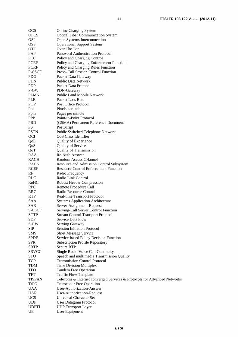
4.1 Determination of e2e QoS scenarios There are basically two different scenarios for end-to-end QoS with hybrid LTE connections plus the scenario of homogeneous LTE and its end-to-end QoS.
1) The LTE terminal is connected to a terminal which is outside of the NGN, e.g. to an ISDN terminal (see figure 1): in such cases the IMS based QoS control will end at the NGN-to-ISDN gateway; the QoS aspect of the remaining part of the connection is not considered. However, in such sense this is not much different for LTE compared to any other NGN access technologies.
NGN with e2e IMS
2 User
1 ISDN-Phone
1 Comm-link
1 Smart phone
1 ISDN to IP GW
1LTE access
point
1NGN with e2e
IMS
Symbol Count Description
Voice Call ISDN to LTE
X to LTE Scenario #1
Figure 1: e2e QoS scenario #1
ETSI
ETSI TR 103 122 V1.1.1 (2012-11) 13
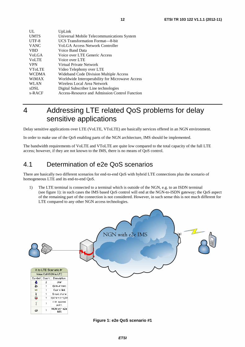
2) The LTE terminal is connecting to another terminal in the NGN with IMS implemented end-to-end (see figure 2): in such cases the QoS control architecture developed by TISPAN (RACS) will ensure proper QoS associated with these services in fixed part of network and QoS control architecture developed by 3GPP (PCC) will ensure proper QoS associated with these services in mobile part of network. Unfortunately, according to the findings presented in clause 6, those two different QoS control architectures are not able to efficiently exchange the required information. This problem has to be solved with highest priority to ensure proper QoS control over entire connection.
Figure 2: e2e QoS scenario #2
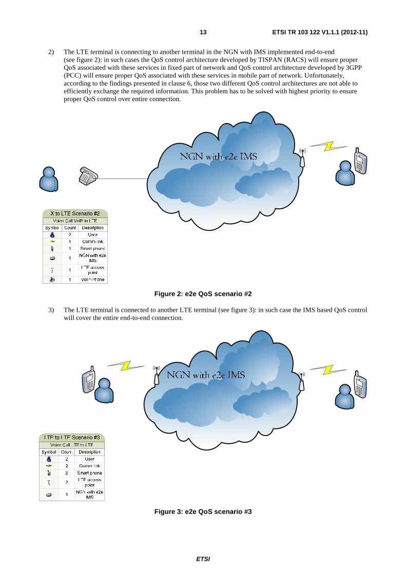
3) The LTE terminal is connected to another LTE terminal (see figure 3): in such case the IMS based QoS control will cover the entire end-to-end connection.
Figure 3: e2e QoS scenario #3

ETSI
ETSI TR 103 122 V1.1.1 (2012-11) 14
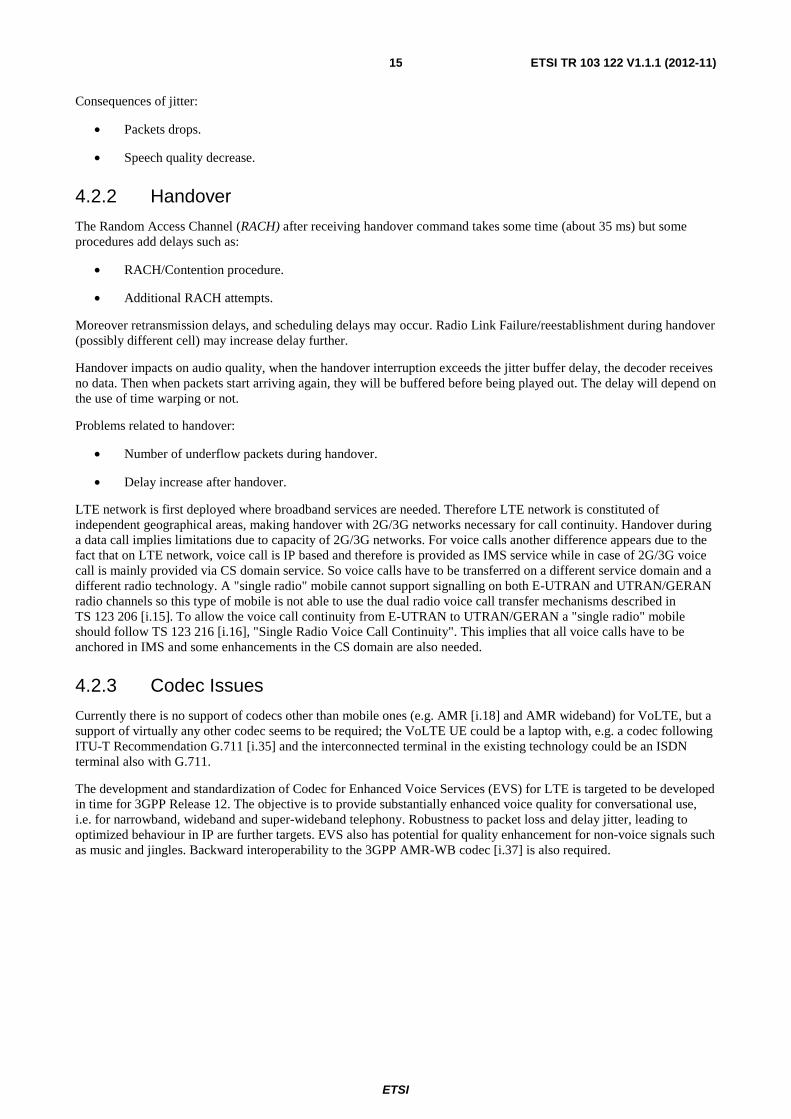
Figure 4 shows all the equipment that may be involved in a Voice call or Videotelephony over LTE. For each equipment the QoE and QoS parameters are listed.
Figure 4: Illustration of e2e LTE voice connection options
4.2 General considerations Based on the above mentioned scenarios the following general considerations are formulated.
4.2.1 Jitter Buffer Problems
Jitter buffer is needed to minimize delay variation introduced by the packet network. Functional requirements for jitter-buffer management and Minimum performance requirements for jitter-buffer management are given in TS 126 114 [i.20] but no algorithm is standardized. The implementation is manufacturer dependent. Jitter buffer can be adaptive or fixed.
Increased jitter will increase the adaptive jitter buffer level increasing end-to-end delay; large jitter may introduce buffer under/overflows, translating delays into erasures. Some procedures such as time warping may be used to reduce under/overflow. This procedure has an influence on the quality of decoded speech and is also language dependent.
Causes of jitter:
• UL/DL scheduling delays.
• Radio retransmissions.
• Core network and device processing jitter.
• Handover.
OTT
UE
Access network =
LTE
E-NodeB
Core network= EPC
MME
S-GW P-GW
PCRF
IMS- IP Backbone
Access network=
LTE
E -NodeB
UE
OTT
QoE parameters: -
Technical parameters (resolution, frame rate, codecs, bit rate…)
- Mobile device (phone size, type of screen…)
- Type of contents, conditions of implementation, viewing environment
- Type of users
QoS parameters
TFT filters are responsible for the distribution of SDFs (service data flow) between bearers
in
UL.
QoS parameters :
Radio bearer
- Ensures the allocation of radio resources (scheduler).
- Provide admission control and management of radio bearers
- Guarantees GBR bearer en DL.
- Imp oses the MBR and the UE-AMBR by scheduling in UL.
- Ensures marking of packets in UL based on QCI bearer at the IP transport (ex DSCP).
HSS
QOS parameters :
S1 and S5/8 Bearer
At the S-GW -
Ensures marking of packets in UL based on QCI bearer at the I P transport (ex DSCP)..
At the P-GW : -
TFT filters are responsible for the distribution of SDFs (service data flow) between bearers
in
DL. -
Limitation of downstream rate based on the accumuled MBRs of the SDF with the same QCI GBR.
- Limitation of t he bandwitch(rate) following the service.
- Imposes the APN-AMBR in DL and UL
QoS parameters
-Diffserv -Dedicated VPN
QoS parameters -
Allows the application of Qos parameters by the transport layer.
- Asks to the P-GW to establish, modifiy and release «
dedicated bearer
» o n the basis of
QOS desired by the user
ETSI
ETSI TR 103 122 V1.1.1 (2012-11) 15
Consequences of jitter:
• Packets drops.
• Speech quality decrease.
4.2.2 Handover
The Random Access Channel (RACH) after receiving handover command takes some time (about 35 ms) but some procedures add delays such as:
• RACH/Contention procedure.
• Additional RACH attempts.
Moreover retransmission delays, and scheduling delays may occur. Radio Link Failure/reestablishment during handover (possibly different cell) may increase delay further.
Handover impacts on audio quality, when the handover interruption exceeds the jitter buffer delay, the decoder receives no data. Then when packets start arriving again, they will be buffered before being played out. The delay will depend on the use of time warping or not.
Problems related to handover:
• Number of underflow packets during handover.
• Delay increase after handover.
LTE network is first deployed where broadband services are needed. Therefore LTE network is constituted of independent geographical areas, making handover with 2G/3G networks necessary for call continuity. Handover during a data call implies limitations due to capacity of 2G/3G networks. For voice calls another difference appears due to the fact that on LTE network, voice call is IP based and therefore is provided as IMS service while in case of 2G/3G voice call is mainly provided via CS domain service. So voice calls have to be transferred on a different service domain and a different radio technology. A "single radio" mobile cannot support signalling on both E-UTRAN and UTRAN/GERAN radio channels so this type of mobile is not able to use the dual radio voice call transfer mechanisms described in TS 123 206 [i.15]. To allow the voice call continuity from E-UTRAN to UTRAN/GERAN a "single radio" mobile should follow TS 123 216 [i.16], "Single Radio Voice Call Continuity". This implies that all voice calls have to be anchored in IMS and some enhancements in the CS domain are also needed.
4.2.3 Codec Issues
Currently there is no support of codecs other than mobile ones (e.g. AMR [i.18] and AMR wideband) for VoLTE, but a support of virtually any other codec seems to be required; the VoLTE UE could be a laptop with, e.g. a codec following ITU-T Recommendation G.711 [i.35] and the interconnected terminal in the existing technology could be an ISDN terminal also with G.711.
The development and standardization of Codec for Enhanced Voice Services (EVS) for LTE is targeted to be developed in time for 3GPP Release 12. The objective is to provide substantially enhanced voice quality for conversational use, i.e. for narrowband, wideband and super-wideband telephony. Robustness to packet loss and delay jitter, leading to optimized behaviour in IP are further targets. EVS also has potential for quality enhancement for non-voice signals such as music and jingles. Backward interoperability to the 3GPP AMR-WB codec [i.37] is also required.

ETSI
ETSI TR 103 122 V1.1.1 (2012-11) 16
4.2.4 V.152 and T.38 transmissions
The fast-paced migration to IP-based communications has generated a need for transmitting voice-band data (VBD), such as fax and data modem signals, over the IP network. This can be accomplished through the use of gateways to interface between the PSTN and IP networks. Two general methods for transmitting fax communication over the IP network are fax pass-through and fax relay. Fax pass though transmits the fax signals as audio compressed with a suitable codec, such as G.711 [i.35]. Fax relay demodulates the incoming fax data at the gateway and transmits the pertinent information over the IP network to the remote gateway so that it may be modulated and sent to the remote fax machine. Methods for performing fax pass though and relay have been standardized in ITU-T Recommendations V.152 [i.49] and T.38 [i.44], respectively. While both V.152 and T.38 allow existing PSTN fax machines to transmit images over the IP network, each one has its advantages and drawbacks.
The most significant advantage of V.152 is its simplicity. This allows V.152 to be implemented quicker and with less potential for interoperability issues than T.38. A V.152 implementation also consumes less MIPS and memory than a T.38 implementation. V.34 fax is supported natively by V.152 as well, because the fax signals are simply sent as audio to the remote end. Since V.152 only uses RTP for transport, it is easier to add support for additional RTP-based features, such as Secure RTP (SRTP).
The most significant advantage of T.38 is its lower bandwidth consumption. Since the fax signals are transmitted after demodulation, the full bandwidth of an audio call is not necessary. It is also simpler to implement redundancy for the transmitted data when using UDPTL with T.38 as compared to RTP. Currently, T.38 is more commonly used for facsimile transmission than V.152.
Comparison of Facsimile Transmission over T.38 and V.152, Website: http://www.vocal.com/voip-voip-software/comparison-of-facsimile-transmission-over-t-38-and-v-152/, [online], latest access 18 June 2012).
Some known issues are:
• T.38 is not sensible on delay, but during the TDM / IP Transit Scenario with more TDM / IP segments T.38 does not work. The cause are timers of the T.38 implementations. For this reason T.38 cannot be used in the TDM / IP transforming period.
• The end-to-end functionality of terminals is only ensured if the same protocol implementation options are used. ITU has standardized 6 versions of T.38. Today only the first version is implemented in the terminals. The transmission rate is 14,4 Kbit/s Fax conforming to ITU-T Recommendation V.17 [i.46].
• If Holding-band characteristics are not implemented (as in many gateways to date), it can lead to situations, where the echo canceller is switched off, even if it should be switched on again. This can be the case in the following situation: V.17 [i.46] Fax or T.38 calls Fax conforming to ITU-T Recommendation V.34 [i.47] -> Answer tone will be for V.34 (-> EC off), connection will be V.17 (EC should be on). In this case the Fax transmission is not possible.
4.2.5 DTMF
The Dual Tone Multi-Frequency (DTMF) signalling system originally described by ITU-T Recommendation Q.23 [i.43] is further specified in EG 201 235, parts 1 to 4 [i.4], [i.5], [i.6] and [i.7].
Whereas, in traditional telephone networks such tones have been carried in-band in the voice channel, in packet based networks they should be transferred as RTP payload as defined in RFC 4733 [i.32]; separate RTP payload is desirable since low-rate voice codecs cannot be guaranteed to reproduce these tone signals accurately enough for automatic recognition-low bit-rate codecs render DTMF tones unintelligible.

ETSI
ETSI TR 103 122 V1.1.1 (2012-11) 17
4.2.6 Resource Allocation
Two resource and admission control solutions defined by 3GPP or ETSI are currently mainly deployed in the telecommunication networks. Those resource and admission control architectures/solutions vary considerably in architecture, supported networks and node types. ETSI TC TISPAN (Telecoms & Internet converged Services & Protocols for Advanced Network) has defined the Resource and Admission Control Subsystem (RACS) to solve the QoS problem of NGN bearer network, mainly from the perspective of fixed access. Being a part of the NGN, the RACS associates resource requirements of the service layer, e.g. IP Multimedia Subsystem (IMS), with resource allocation of the bearer layer, and performs such functions as policy control, resource reservation, admission control and Network Address Translation (NAT). By means of series of QoS policies, the RACS enables the Application Function (AF) to control the transport layer, thus allowing user terminals to get services with guaranteed QoS. On the other hand, the 3rd Generation Partnership Project (3GPP), mainly providing standards for mobile communications has defined the Policy and Charging Control (PCC) architecture to enforce resource and admission control. Lying between the service control layer and the access/bearer layer, the PCC is developed to follow the characteristics of mobile access networks to achieve certain QoS control.
In principle, the resource allocation issue is closely related to different quality classes.
Table 1: PCC quality classes
QCI RESOURCE TYPE
PRIORITY PACKET DELAY
BUDGET
PACKET ERROR LOSS RATE
EXAMPLE SERVICE
1 GBR 2 100 ms 10-2 Conversational voice 2 GBR 4 150 ms 10-3 Conversational voice (live streaming) 3 GBR 3 50 ms 10-3 Real-time gaming 4 GBR 5 300 ms 10-6 Non-conversational video (buffered
streaming) 5 Non- GBR 1 100 ms 10-6 IMS signalling 6 Non- GBR 6 300 ms 10-6 Video (buffered streaming), TCP-based 7 Non- GBR 7 100 ms 10-3 Voice, video (live streaming),
interactive gaming 8 Non- GBR 8 300 ms 10-6 Video (buffered streaming), TCP-based
(e.g. www, e-mail, chat, ftp, p2p file sharing, progressive video, etc.)
9 Non- GBR 9 300 ms 10-6
In a typical case, multiple applications may be running in a UE at any time, each one having different quality of service requirements. For example, a UE can be engaged in a VoIP call while at the same time browsing a web page or downloading an FTP file. VoIP has more stringent requirements for QoS in terms of delay and delay jitter than web browsing and FTP, while the latter requires a much lower packet loss rate. In order to support multiple QoS requirements, different bearers are set up within the Evolved Packet System, each being associated with a QoS. Broadly, bearers can be classified into two categories based on the nature of the QoS they provide:
• Minimum guaranteed bit rate (GBR) bearers that can be used for applications such as VoIP. These have an associated GBR value for which dedicated transmission resources are permanently allocated (for example, by an admission control function in the eNodeB) at bearer establishment or modification. Bit rates higher than the GBR may be allowed for a GBR bearer if resources are available. In such cases, a maximum bit rate (MBR) parameter, which can also be associated with a GBR bearer, sets an upper limit on the bit rate that can be expected from a GBR bearer.
• Non-GBR bearers that do not guarantee any particular bit rate. These can be used for applications such as web browsing or FTP transfer. For these bearers, no bandwidth resources are allocated permanently to the bearer.
In the access network, it is the responsibility of the eNodeB to ensure the necessary QoS for a bearer over the radio interface. Each bearer has an associated QCI, and an Allocation and Retention Priority (ARP).
Each QCI is characterized by priority, packet delay budget and acceptable packet loss rate. The QCI label for a bearer determines how it is handled in the eNodeB. Only a dozen such QCIs have been standardized so that vendors can all have the same understanding of the underlying service characteristics and thus provide corresponding treatment, including queue management, conditioning and policing strategy.
ETSI
ETSI TR 103 122 V1.1.1 (2012-11) 18
This ensures that an LTE operator can expect uniform traffic-handling behaviour throughout the network regardless of the manufacturers of the eNodeB equipment. The set of standardized QCIs and their characteristics (from which the PCRF in an EPS can select) is provided in table 1. The QCI table specifies values for the priority handling, acceptable delay budget and packet loss rate for each QCI label. The priority and packet delay budget (and to some extent the acceptable packet loss rate) from the QCI label determine the RLC mode configuration and how the scheduler in the MAC handles packets sent over the bearer (for example, in terms of scheduling policy, queue management policy and rate-shaping policy). For example, a packet with higher priority can be expected to be scheduled before a packet with lower priority. For bearers with a low acceptable loss rate, an acknowledged mode (AM) can be used within the RLC protocol layer to ensure that packets are delivered successfully across the radio interface.
4.2.7 Delay Budgets
The transmission delay is an important speech quality characteristic, guidance is given in ITU-T Recommendation G.114 [i.51]. The delay requirement for the UE is specified in TS 143 050 [i.23].
For LTE the following variable factors influence the delay budget:
• In downlink this is mainly the size and the algorithm of the de-jitter buffer.
• In uplink the delay depends on the CDRX scheduling (20 ms or 40 ms).
CDRX configuration enables tradeoff between E2E delay and power consumption:
• E2E delay-optimized configuration - 20 ms CDRX and no packet bundling.
• Power/capacity-optimized configuration - 40 ms CDRX along with 2-packet bundling in UL/DL.
4.2.8 Discontinuous Reception (DRX)
Discontinuous Reception (DRX) is nothing new for UMTS based networks, and is a power reduction feature. The aim is simple - during idle periods, the cellular network tells the handset that it doesn't need to expect any traffic, and thus the handset can shut down the RF frontend and other power draining bits. The UE can then wake up the parts required to receive and listen to a paging channel when the discontinuous cycle ends.
2G and 3G terminal use discontinuous reception (DRX) in idle mode, whereas in LTE there is similar DRX however both in idle and connected mode. By idle mode, it is understood that the UE is not utilizing radio resources. Whereas in connected mode, UE utilizes radio resources and battery consumption is very high due to 'over the air' communication between mobile terminal and the network. In LTE when there is no data to receive or transmit, UE would switch off its transceiver for a very short interval. It will start similar "wake up and sleep" cycle to check whether there is some data that it has to either receive or send. This DRX feature in connected mode (CDRX) is likely to save a lot of battery usage for consumers.
The "connected" part comes from the fact that DRX now can work while the user equipment is in an RRC_Connected state, in addition to RRC_Idle. The result is that the UE can now shut down parts required to listen with much finer frequency, for example during the idle periods when a webpage is loading, as opposed to the longer idle periods when the phone is locked and in a pocket.
The following definitions, taken from: TR 121 905 [i.9] will help to understand the previous text:
- Connected Mode: Connected mode is the state of User Equipment switched on and an RRC connection established.
- Radio Resource Control: A sublayer of radio interface Layer 3 existing in the control plane only which provides information transfer service to the non-access stratum. RRC is responsible for controlling the configuration of radio interface Layers 1 and 2.
ETSI
ETSI TR 103 122 V1.1.1 (2012-11) 19
4.2.9 Characteristics of LTE media quality
User perception of the overall merits of a VoLTE call is determined by the time spent setting it up, and the quality of the speech (and eventual video) aspects of the session. Speech quality varies according to a number of factors relating to the terminal and the network. For terminals, speech quality depends on the performance of the microphone and speaker, as well as the functionality to handle echo, background noise, compensation of speech level, and especially the speech codec and jitter-buffer management (JBM). Video quality is also determined by a combination of factors, even more of which are terminal-related than with speech. The quality of JBM, the camera and display, the appropriate video codec, the settings of frame-rate and image fidelity for the format used, as well as the adaption of speech versus video delay (lip-synch alignment) all affect user-perceived video quality. In the absence of media gateway functions, the network impacts speech and video quality in terms of transport and mobility. The network mainly affects quality through available bandwidth, packet loss (which causes speech/video frame error), and delay as well as interruption time at handover. Except for the speech- and video-path delay factor, the impact of all other speech and video quality factors is the same, regardless of whether the call is handled over a circuit-switched (3G/2G) or a packet switched (LTE) network.
For calls over CS, the delay is fixed on both an E2E and on a node level for their entire duration. For calls over PS, a large amount of jitter is introduced in the LTE radio network - as a result of speech- and video-quality and network-capacity/coverage optimization. Despite the introduction of jitter, the target is still to provide a fixed E2E delay for PS-call users. The two factors directly related to the LTE radio network that impact the quality of speech and video are packet delay and packet loss rate. These factors are, in turn, highly dependent on the capability of the LTE radio network to perform link adaptation and packet scheduling under various load and interference conditions, while maintaining efficient use of the radio-interface resources. (Link adaptation refers to the ability to change transmission mode based on the radio condition of the terminal and packet scheduling refers to the prioritization of packets between different terminals and IP flows). The use of L2 HARQ retransmission in LTE can create significant additional jitter in packet delivery; some packets may be delivered on first transmission, while others may use up to the maximum configured number of retransmissions to be delivered successfully. The dynamic nature of the packet scheduler may also introduce significant jitter, at times transmitting packets as soon as they arrive and at other times, very close to the maximum delay budget (taking into account the HARQ retransmissions). In some cases, the handling techniques lead to the late arrival of packets, which - from a quality perspective - results in a lost (faulty) speech or video frame. The JBM in the terminal needs to be designed so that the user perceives delay variations caused in the radio network as negligible.
4.3 Relations to other radio-link technologies (mainly UMTS) With a view to the migration from existing radio access technologies it is important that at least in reality LTE and other radio channels cannot be used at the same time by the same terminal.
In 2G/3G the bandwidth requirement for the media channel across the radio link is well established and available for all QoS related instances. Whereas in 2G/3G the selection of possible codecs, e.g. for voice communication is clearly limited, LTE terminal designers can choose among (in principle) all available codec types; this choice is limited only by the fact that if the codec type cannot be addressed in an SIP environment, IMS will not be able to handle such cases.
Without a well-defined bandwidth for each of such codecs, they cannot be used efficiently in the LTE access; thus it seems that a number of "profiles" should be defined determining the proper bandwidth and other codec specific parameters.
In addition, some problems currently occurring in UMTS world will probably appear in LTE world soon. Those problems are listed below.
4.3.1 Load of the network
In order to keep the delay as low as possible, one frame per packet of AMR [i.18] (or AMR WB) would be used.
Robust Header Compression was not mandatory in the terminal so that this algorithm cannot be used. This leads to an overhead; three bytes are needed for the payload and table of content and 40 bytes for IPv4 header. For example, transmission of AMR 12,2 kb/s requires 74 bytes per packet, so that a 32 kb/s PS conversational bearer is needed.

ETSI
ETSI TR 103 122 V1.1.1 (2012-11) 20
4.3.2 Delay
The theoretical delay is composed of delay in the terminal, delays in the network.
In the terminal, on encoder side, some delays have to be taken into account due to the framing, the look-ahead, the processing and the packetization: 45 ms. Then the transmission is affected by delay due to interleaving/de-interleaving leading to Uplink delay between UE and Iu of 84,4 ms and to Downlink delay between Iu and Ue: 71,8 ms. Some more delay is generated by core network delay but only a few ms. Routing through IP, the delay is depending on the number of routers and on traffic load.
Delay on decoder side should take into account jitter buffer, de-packetization and processing.
One way delay in a mobile Voice over IP over UMTS communication is at least: 240 ms.
4.3.3 Drawback of IPv6 usage
With the adoption of IPv6, 20 bytes are added to the header. Moreover, the header IPv6 does not contain the header checksum so that checksum of UDP has to be used to protect the IPv6 header. The drawback is that the whole packet will be dropped even if errors are on bits of the less sensitive class. Then UDPLite helped preventing this problem.
4.4 QoS problems encountered by operators Personal discussions with network operators and stakeholders have been realized in order to create a list of their QoS problems. All contacted operators and stakeholders have trialled LTE technology. Most of the trials have been focused on a performance of data services and have been made as lab implementation. Only one of the contacted stakeholders has focused on voice service in its trial. Some problems with CS Fallback (was not working properly) and problem with routing between radio part (LTE network) and IMS have been reported. Those problems have been fixed by vendor (wrong implementation).
In addition there are the following foreseen problems:
• Call setup delay Call setup delay should be measured for Voice over LTE; at least in two cases, voice call alone when the UE is not yet in communication and also voice call when the terminal is already in other data connection. Different types of user equipment should be used for the trial.
• Frame loss rate Packet drops from jitter buffer under/overflow had to be added to the one coming from the transmission over the air. This increases the total loss rate and modifies the loss model. Error correction unit is implementer dependent, the quality of resulting decoded speech may decrease.
According to the answers received by the contacted network operators and stakeholders, we can conclude that operators have not already started to deploy Voice over LTE in their networks. On the other hand, according to well-respected market observers/visionaries, operators are planning to deploy VoLTE in 2013.
Review of visionary articles from stakeholders and market observers:
1) On 15 May 2012, Thomas Nilsson, CTO, Polystar, commented on the Official LTE World Series Blog:
"The subscribers that will migrate to LTE are most likely the ones that today use good performing and well-functioning data services in 3G. Moving to LTE, those subscribers' expectations will increase even more. Apart from super-fast browsing, they will expect services that take advantage of the lower latency, such as voice and video."
and
"Today, voice is provided through CS fallback or VoLTE, with CSFB the choice when a legacy 3GPP network is available. I see 2013 as the year where VoLTE, delivered under an IMS umbrella, will move beyond the early adopters and grow a larger commercial footprint. Even though voice will represent only a small portion of all data transmitted in an LTE network, it will remain a key service with high-performance expectations. To meet these expectations, it will be essential to keep track of the delivered voice quality."

ETSI
ETSI TR 103 122 V1.1.1 (2012-11) 21
Meet customer expectations with your LTE offering, Website: http://lteconference.wordpress.com/2012/05/15/meet-customer-expectations-with-your-lte-offering/, [online], latest access 19 June 2012.
2) On 28 November 2011 Michelle Donegan, European Editor, Light Reading Mobile, commented:
"To date, only CDMA operators like Verizon Wireless and MetroPCS Inc. (NYSE: PCS) have supported voice calls on LTE smart phones by having more than one radio active in the device -- one for the packet-based LTE data service and another for circuit-switched CDMA voice service.
Now, GSM operators like AT&T Inc. (NYSE: T), Rogers Communications Inc. (Toronto: RCI) and soon TeliaSonera AB (Nasdaq: TLSN) can also support voice on their LTE smart phones. The LTE devices will have multiple radios to support LTE, UMTS and even GSM, but with CS fallback only one radio can be active at any time. So, the device is forced off the LTE network and onto the 2G or 3G network for voice calls."
and
"According to Heavy Reading's Brown, a majority of operators are launching CS fallback because it's a "time-to-market issue" before voice over LTE (VoLTE) will be commercially available, which Brown says will be in the first quarter of 2013."
Operators Raise Voice Services on LTE, Website: http://www.lightreading.com/document.asp?doc_id=215057, [online], latest access 19 June 2012.
3) On 24 May 2012 Michelle Donegan, European Editor, Light Reading Mobile, reported:
"Here at the LTE conference in Barcelona, Danish operator TDC A/S (Copenhagen: TDC)'s director of mobile systems Ove Andreasen summed up the significance of getting VoLTE right...
The worry is that the more all-IP LTE networks are rolled out and the longer mobile operators take to launch VoLTE, the window of opportunity widens all the more for over-the-top voice and messaging players.
According to Andreasen, VoLTE won't take off earlier than the second half of next year (2013) in Europe, at least."
and
"According to Bengt Nordstrom, founder of consultancy Northstream, the situation with VoLTE is worse than what he was hoping.
"The understanding I have had is that we knew we could launch LTE in 2009 with routers and dongles; then with handsets using [circuit-switched fallback] and then VoLTE," he said. "But the industry has not sorted out how [VoLTE] should be implemented. It's not like it will be fully working in 2013 -- it's more like 2014.""
4G Voice Still Just a Whisper, Website: http://www.lightreading.com/document.asp?doc_id=221315, [online], (latest access 19 June 2012).
4) On 2 February 2012, Brooke Crothers, CNET Blog Network author, summarizes:
"...completed a major hurdle that will enable Voice-over-LTE (VoLTE).
The technology, called Single Radio Voice Call Continuity, or SRVCC, enables continuity of service by seamlessly switching to a WCDMA network when a consumer on a VoLTE call leaves the LTE network's coverage area,..."
and
"Ultimately the goal is to have one less modem chip to worry about and therefore slimmer, less power-hungry LTE phones. And how is this achieved? An acronym-packed backgrounder is provided by Qualcomm.
"SRVCC is the next logical step in...4G LTE voice...following the commercial launch of circuit-switched fallback technology (CSFB) on smart phones in 2011. Circuit-switched fallback technology (CSFB) allows a single radio in the handset to dynamically switch from an LTE data connection to a 3G connection when the user needs to make or receive a call. Similarly, SRVCC support enables a single radio in the handset to execute a seamless handover of a voice call from an LTE network to a 3G network."
ETSI
ETSI TR 103 122 V1.1.1 (2012-11) 22
And SRVCC and CSFB allow both LTE and 3G network connections to be supported on a single chip. The upshot: no need for separate LTE and 3G radios and modems...
"This new development eliminates the need for a second modem chip, thereby reducing the cost and even size of future 4G/LTE handsets."..."
Qualcomm's Snapdragon on track for Voice over LTE, Website: http://news.cnet.com/8301-13924_3-57370121-64/qualcomms-snapdragon-on-track-for-voice-over-lte/?part=rss&subj=latest-news&tag=title, [online], latest access 19 June 2012.
To sum up the current situation, according to the market observers/visionaries, network operators are planning to deploy VoLTE in upcoming years. The potential subscribers of LTE expect better performing data services than in 3G and services that take advantage of the lower latency, such as voice and video. In other words, quality of service will play a very crucial role in an adaptation process of LTE.
5 Overview of shortcomings, identified As can be seen below, a few very important shortcomings of standards have been identified. In principle, most of them should be solved with highest priority to ensure reliable interworking between LTE and other network technologies from delay sensitive services perspective and to satisfy the high quality expectations of potential users of VoLTE in heterogeneous environment, as reported by market observers/visionaries. On the other hand, three different perspectives of shortcoming of implementations have been investigated, namely shortcoming of interim solutions, problems related to migration of voice service to LTE and shortcoming of VoLTE Interoperability test event. Most of the identified problems or shortcoming should be carefully considered in trials which will happen before real adoption of VoLTE in the networks.
5.1 Shortcomings of Standards, Overview In total, there are four main standards focusing on IMS Multimedia Telephony, IMS Profiles for voice service, SMS and conversational video service. Main parts of those standards focusing on QoS are reviewed in clause 6.1. As can be seen in clause 6.1.1, the MTSI client defined in TS 126 114 [i.20] should support AMR [i.18] codec for voice service and codecs conforming with ITU-T Recommendation H.263 [i.40] and H.264 [i.41] for video service. One would expect that more codecs will be supported by MTSI client following basic ideology of IMS. The basic ideology of IMS is to be codec-independent. It seems to be advisable to extend the support of MTSI client towards other codecs supported by SIP (signalling protocol fully supported by IMS). In addition, the jitter-buffer management mechanisms of video service described in the same document seem to be very weak. To ensure a proper service quality, similar functional requirements and minimum performance requirements for jitter-buffer management including some delay and error profiles similarly as for voice should be also specified for video service. Finally, the quality of experience metrics defined in clause 16 of TS 126 114 [i.20] and listed below in clause 6.1.1 can be more or less only considered as QoS parameters. The list provided in TS 126 114 [i.20] should be extended in order to cover all important QoE parameters in this context. In addition, the recommended range of those parameters should be mentioned in the document. When this is done, the quality measurements described in the same clause of TS 126 114 [i.20] can provide QoE server with more valuable quality information which will enable us to improve the quality of the monitored service markedly by deploying adaptation mechanisms described also in the same document or in a scientific literature.
Two resource and admission control solutions defined by 3GPP or ETSI are currently mainly deployed in the telecommunication networks. Those resource and admission control architectures/solutions vary considerably in architecture, supported networks and node types. Having recognized that the promotion of three diverging IMS standards for mobile, fixed and cable networks, respectively, entails the severe danger of an overall IMS failure, 3GPP has agreed in 2007 together with other involved standardization organizations, notably ETSI TISPAN for fixed networks and PacketCable for cable networks, to harmonize their corresponding standardization activities. This activity has been officially called "Framework for Gq'/Rx harmonization". Starting with 3GPP Release 8, the 3GPP therefore has developed and promoted a Common IMS architecture which conforms to the requirements of all three standardization bodies, whereas in 3GPP Release 7, main QoS-related interfaces (reference points), particularly Rx/Gx for 3GPP and Gq'/Re for the Resource and Admission Control Subsystem (RACS), have not been harmonized.

ETSI
ETSI TR 103 122 V1.1.1 (2012-11) 23
Unfortunately, the harmonization activity mentioned above [i.1] has been abandoned and all published specifications have been withdrawn. The detailed comparison of the most deployed Resource and Admission Control Architectures from functional, interfaces and procedures perspectives is presented in clause 6.2. As can be seen in clause 6.2, there are big functional differences as well as differences with regard to the interfaces and procedures involved in both architectures. Despite these facts, experts believe that those architectures can be harmonized and merged. It seems that this belief was a driving idea for creating Framework for Gq'/Rx harmonization" aiming at analyzing and comparing 3GPP PCC and TISPAN RACS architectures. As a result, some of the mentioned differences have been worked out within this framework, like globally unique address, Network Address and Port Translation control and soft-state model but unfortunately those solutions have been lost due to withdrawal of all specifications created by this framework. However, the differences between the two architectures and the relevant interfaces, especially the Gq' interface between RACS and upper-layer control (such as P-CSCF) and the Rx interface between PCC and upper-layer control will have great impact on equipment manufacture, and also influence network deployment. On the other hand, several TISPAN RACS's can currently interact with each other, although related communication interface and specifications are to be further improved. However, no interface is available for communication between the TISPAN RACS and the 3GPP PCC. Consequently, they cannot coordinate with each other. When a subscriber is handed over between heterogeneous networks, continuous QoS control has to be implemented among the heterogeneous networks to satisfy the subscribers' service experience. That is to say, the TISPAN RACS and the 3GPP PCC have to interact and negotiate with each other in order to finish the operations required for continuous QoS guarantee, for instance, resource reservation.
To achieve coordination between the TISPAN RACS and 3GPP PCC, it is necessary to study and standardize the interactive interface between them. This activity has been previously covered by "Framework for Gq'/Rx harmonization".
5.2 Shortcomings of Implementations, Overview Except from pure VoLTE that requires significant investment in network infrastructure (e.g. network wide IMS) and thus is considered as ubiquitous for next years, the following interim solutions have been identified. Their principal shortcomings are summarized below:
• Circuit-switched fallback (CSFB): Uses 2G/3G for voice and requires interruption of the LTE connection; this is already affected by the signalling of an incoming call.
• Voice over LTE Generic Access (VoLGA): Tunnels the voice call from the 2G/3G to the LTE terminal via an LTE data channel; requires additional equipment in the network; lack of QoS.
• Fast Track VoLTE: Proprietary solution providing voice service via the LTE technology; adds SIP stack to existing mobile network equipment.
• Over-the-Top solutions (OTT): VoIP applications operating via an LTE data channel, running on the LTE terminal; lack of QoS.
NOTE: There are discussions to provide OTT with improved QoS based on the use of deep packet inspection.
To facilitate the necessary migration of voice service to LTE, extensive work needs to be carried out so that the mobile-broadband capabilities of LTE networks reach the same coverage and reliability levels, as is possible for circuit-switched voice in 2G and 3G networks. When compared to its predecessors, LTE differs in many ways. Most significantly, the nature of dynamic scheduling coupled with variable retransmissions, interspersed with inter-cell handover, can introduce significant jitter. Voice now represents a smaller fraction of total device usage. It does, however, remain an essential capability, and user expectations for voice are very high. If voice services do not deliver the necessary level of quality and reliability, users will revert back to existing circuit-switched options or, in some cases, simply rely on over-the-top solutions. To meet VoLTE performance targets, JBM for the UE needs to meet specifications, and the delay contribution from other (post-decoder) UE internal processing outside the normal functionality should be negligible. Efforts to validate VoLTE from an E2E perspective have the key objective of retaining users. In Germany in early 2011, the first solution for wireless voice over IP using an LTE network was commercially deployed, validating many of the QoS and scheduler enablers that are required for VoLTE.
The first Voice over LTE (VoLTE) Interoperability 2011 event took place from September 12th-30th, 2011. The event was organised by the Multi-Service Forum (MSF) and backed by the GSMA.
Whitepaper MSF VoLTE Interoprabilty Event 2011, Website: http://www.msforum.org/interoperability/MSF_VoLTE%20_2011_WhitePaper.pdf, [online], latest accessed 20 June 2012.
ETSI
ETSI TR 103 122 V1.1.1 (2012-11) 24
The VoLTE Interoperability Event 2011 test environment was based on:
1) Proving multivendor interoperability of Evolved Packet Core network nodes.
2) QoS control as an essential underpinning for services using PCC architecture and binding to the application layer in IMS.
3) Proving multivendor interoperability between IMS network nodes.
4) Proving VoLTE, including MMTel services via EPC and IMS, including interaction with the PCC architecture.
5) Roaming between EPC capable networks, including proving VoLTE and MMTel services for the roaming UE.
6) Proving VoLTE, including MMTel services, via the interconnect between IMS networks.
7) Intra-LTE Handover.
8) Robustness testing of EPC network nodes.
MSF reports in the white paper mentioned above that:
"The event proved that VoLTE is a viable solution for providing voice services over LTE access technology, and can be deployed with roaming and interconnect functionality to provide equivalent service as CS-based voice services today."
Such statements raise the issue of what exactly has been tested and what kind of understanding of the terms "Quality of Service" and "service" have been prevalent. A more detailed view into the scenarios of this interoperability event, e.g. scenario 1a, as depicted in figure 8 (see clause 7.3.3) unveils that QoS of the media channel is not tested at all.
The following VoLTE test event had been announced by the MSF for October 2012, see:
MSF Press Release "RCS VoLTE Interoperability Event 2012", Website: http://www.msforum.org/pressroom/pr/RCS%20VoLTE%20PR%20Announcement%20_4_24_2012.pdf, [online], latest accessed 20 June 2012.
It is indicated in this press release that the specifications for the tests are provided in collaboration with ETSI INT.
Summary of the upcoming event:
http://www.msforum.org/interoperability/RCSVoLTE.shtml, [online], latest accessed 14 September 2012.
The event will focus on RCS & VoLTE in the following scenarios:
Home/Single Network: In this scenario a single instance of the RCS VoLTE architecture will be created using components from different vendors. Testing will include attachment and detachment from the network, Tracking Area Update, IP-CAN session establishment, SIP registration (to IMS), SIP session establishment, interaction with IMS Multimedia Telephony, IMS Conversational Video Services and RCS services. This scenario focuses on testing interoperability of the functionality as profiled by GSMA PRDs IR.92 [i.28], IR.94 [i.29], IR.90 [i.27], IR.67 [i.25] and the RCS Services and Client Specification [i.30].
Roaming & Interconnect: In this scenario, the local breakout model with visited P-CSCF and home operator applications is tested. The test set will be the same as for the home/single network case, plus some roaming specific tests to demonstrate the transfer of Policy Rules between home/visited networks, the usage of Diameter Routing Agents, and Session Border Controllers. This scenario focuses on testing interoperability of the functionality as profiled by GSMA PRDs IR.65 [i.24], IR 88 [i.26], IR.92 [i.28], IR.94 [i.29], IR.90 [i.27], IR.67 [i.25] and the RCS Services and Client Specification [i.30]. In addition, an IPX provides the interconnect network between the 2 PLMNs.
The event will also test:
Non-LTE Access: In this scenario, the ‘legacy' 3GPP access types of UMTS (UTRAN) and GSM/EDGE (GERAN) are used to interface to the EPC. The test set will include attachment, IMS registration and IMS session establishment and teardown.

ETSI
ETSI TR 103 122 V1.1.1 (2012-11) 25
Handover: This scenario builds on the previous one and tests the number of handover scenarios. This will include intra-LTE handover (between eNodeBs, MME/S-GW relocation) and handover between LTE and legacy 3GPP (UMTS, GSM/EDGE) access.
Inter-RAT Priority Call Handover: In this scenario the handover of priority voice calls between LTE and other RATs is tested. The scenario tests that voice calls originating as Multimedia Priority Service (MPS) VoLTE calls have relevant priority markings mapped properly when those calls are handed over to another Radio Access Technology (RAT) and the CS-domain and vice versa.
NOTE: Media quality itself is excluded.
5.3 Comparison of shortcomings of standards and implementations with other radio-link technologies (mainly UMTS)
Narrow band telephony, wideband telephony and video telephony were first defined for UMTS in CS domain. Voice calls are then mainly provided on CS domain. When a mobile is already in IP connection when voice call is needed, it is provided as for VoLTE following the MTSI specification.
UMTS Narrow band telephony was the logical continuation of 2G narrow band telephony. However, a limitation had to be made on the mode switching of AMR codec [i.18]. In 2G, it was possible to switch for one AMR mode to another every frame, in 3G this was only every 2 frames.
Introduction of wideband telephony in UMTS was made possible only when using "TFO" or "TrFO", allowing the transfer within the core network without transcoding to G.711 [i.35]. The wideband voice codec, AMR-WB [i.37] is composed of 9 modes. TFO and TrFO work on subset of AMR-WB modes but there are many possibilities to decide on the subsets. Different operators may decide on different subsets making difficult wideband telephony through different operators. By chance it seems that only one mode of AMR-WB [i.37] is used.
Video telephony was introduced in UMTS but some delays issues appeared in call setup time. During call setup, multiple messages conforming to ITU-T Recommendation H.245 [i.39] have to be exchanged in order to establish video telephony transmission, each of them requiring an acknowledgement before the next message being emitted. Then call setup delay was up to 10 s. It was decided to modify the process and send the H.245 [i.39] messages without waiting for the acknowledgments after each message but only for a global acknowledgment. This decision reduced the call setup time to reasonable values.
6 Detailed Review of Standards dealing with IMS Multimedia Telephony and IMS Profiles and Resource and Admission Control Architectures
This clause will deal with a detailed review of two different groups of standards, namely a group of standards focusing on IMS Multimedia Telephony and IMS Profiles for Voice, SMS and Conversational Video Service and a group of standards dealing with Resource and Admission Control Architectures.
6.1 Review of Standards dealing IMS Multimedia Telephony and IMS Profiles for Voice, SMS and Conversational Video Service
In total, there are four main standards focusing on IMS Multimedia Telephony, IMS Profiles for voice service, SMS and conversational video service. Main parts of those standards focusing on QoS will be reviewed in following clauses, respectively.
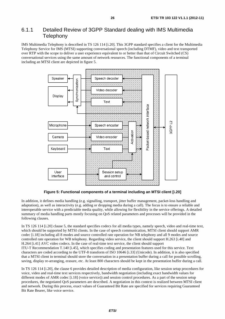
ETSI
ETSI TR 103 122 V1.1.1 (2012-11) 26
6.1.1 Detailed Review of 3GPP Standard dealing with IMS Multimedia Telephony
IMS Multimedia Telephony is described in TS 126 114 [i.20]. This 3GPP standard specifies a client for the Multimedia Telephony Service for IMS (MTSI) supporting conversational speech (including DTMF), video and text transported over RTP with the scope to deliver a user experience equivalent to or better than that of Circuit Switched (CS) conversational services using the same amount of network resources. The functional components of a terminal including an MTSI client are depicted in figure 5.
Figure 5: Functional components of a terminal including an MTSI client [i.20]
In addition, it defines media handling (e.g. signalling, transport, jitter buffer management, packet-loss handling and adaptation), as well as interactivity (e.g. adding or dropping media during a call). The focus is to ensure a reliable and interoperable service with a predictable media quality, while allowing for flexibility in the service offerings. A detailed summary of media handling parts mostly focusing on QoS related parameters and processes will be provided in the following clauses.
In TS 126 114 [i.20] clause 5, the standard specifies codecs for all media types, namely speech, video and real-time text, which should be supported by MTSI clients. In the case of speech communication, MTSI client should support AMR codec [i.18] including all 8 modes and source controlled rate operation for NB telephony and all 9 modes and source controlled rate operation for WB telephony. Regarding video service, the client should support H.263 [i.40] and H.264 [i.41] AVC video codecs. In the case of real-time text service, the client should support ITU-T Recommendation T.140 [i.45], which specifies coding and presentation features used for this service. Text characters are coded according to the UTF-8 transform of ISO 10646 [i.33] (Unicode). In addition, it is also specified that a MTSI client in terminal should store the conversation in a presentation buffer during a call for possible scrolling, saving, display re-arranging, erasure, etc. At least 800 characters should be kept in the presentation buffer during a call.
In TS 126 114 [i.20], the clause 6 provides detailed description of media configuration, like session setup procedures for voice, video and real-time text services respectively, bandwidth negotiation (including exact bandwidth values for different modes of AMR codec [i.18] (voice service)) and session control procedures. As a part of the session setup procedures, the negotiated QoS parameters are described. A negotiation in this context is realized between MTSI client and network. During this process, exact values of Guaranteed Bit Rate are specified for services requiring Guaranteed Bit Rate Bearer, like voice service.

ETSI
ETSI TR 103 122 V1.1.1 (2012-11) 27
In TS 126 114 [i.20], the clause 8 specifies mechanisms to handle delay jitter in MTSI clients in terminals. In particular, the clause provides general functional requirements for jitter-buffer management (voice service) and minimum performance requirements for jitter-buffer management including six different delay and error profiles designed to check the tested JBM for compliance with the minimum performance requirements. The profiles span a large range of operating conditions in which the JBM should provide sufficient performance for the MTSI service. All profiles are 7 500 IP packets long. In addition, the speech files for evaluation of a JBM against the minimum performance requirements are attached to [i.20]. Regarding video service and jitter-buffer implementation, TS 126 114 [i.20] only provides very weak description of jitter-buffer management and leave this point to implementer. In the case of real-time text service, the strict jitter-buffer management is not needed due to minor impact of delay on a performance of real-time text service reported in [i.20].
In TS 126 114 [i.20] clause 9, some methods to handle conditions with packet losses are specified, mainly focusing on redundancy issues (defining redundancy levels for voice and real-time text services and describing transmission of redundant frames).
In TS 126 114 [i.20] clause 10, adaptive mechanisms are defined to optimize the session quality given the current transport characteristics. The mechanisms provided in MTSI are bit-rate, packet-rate and error resilience adaptation. These mechanisms can be used in different ways; however, they should only be used when the result of the adaptation is assumed to increase the session quality even if e.g. the source bit-rate is reduced. Adaptive mechanisms that act upon measured or signalled changes in the transport channel characteristics may be used in a conservative manner. Examples of measured changes in transport characteristics are variations in Packet Loss Rate (PLR) and delay jitter. A conservative use of adaptation is characterized by a fast response to degrading conditions, and a slower, careful upwards adaptation intended to return the session media settings to the original default state of the session. The long-term goal of any adaptive mechanism is assumed to be a restoration of the session quality to the originally negotiated quality. The short-term goal is to maximize the session quality given the current transport characteristics, even if it means that the adapted state of the session will give a lower session quality compared to the session default state if transported on an undisturbed channel.
Finally, in TS 126 114 [i.20] clause 16 provides information about the MTSI Quality of Experience (QoE) metrics feature, which is optional for an MTSI client in a terminal and should not disturb the MTSI service. The following metrics are defined in this clause:
• Corruption duration metric.
• Successive loss of RTP packets.
• Frame rate.
• Jitter duration.
• Sync loss duration.
• Round-trip time.
• Average codec bitrate.
• Codec information.
The parameters mentioned above are measured by MTSI client and can be sent to the QoE server during the session and at the end of the session using the HTTP transport protocol.
6.1.2 Detailed Review of GSMA Permanent Reference Document describing IMS profiles for voice and SMS
IMS profiles for voice and SMS are described/defined in GSMA IR.92 [i.28], which defines the profiles by listing a number of Evolved Universal Terrestrial Radio Access Network (E-UTRAN), Evolved Packet Core, IMS core and UE features which are considered essential to launch interoperable IMS based voice. The defined voice profile is compliant with 3GPP specifications. The scope is the interface between UE and network. GSMA PRD: IR.92 [i.28] is extensively based on TS 126 114 [i.20] and defines minimum mandatory set of features defined in 3GPP specifications that wireless device (UE) and network are required to implement in order to guarantee an interoperable, high quality IMS-based telephony service over LTE radio access. In addition to the features defined in 3GPP standard mentioned above [i.28] specifies LTE Radio Capabilities (radio bearers, DRX modes of operation, radio-link control configurations and GBR monitoring function) and Bearer Management.

ETSI
ETSI TR 103 122 V1.1.1 (2012-11) 28
It is worth noting that the main body of this PRD is applicable for a scenario where IMS telephony is deployed over LTE in a standalone fashion without relying on any legacy infrastructure, packet or circuit switched. Annex A defines the profile for an alternative approach where IMS telephony is deployed with a certain degree of reliance on an existing 3GPP circuit switched network infrastructure.
6.1.3 Detailed Review of GSMA Permanent Reference Document describing IMS profile for Conversational Video Service
Similarly as in previous case, this GSMA document [i.29] provides IMS profile for conversational video service; it is extensively based on TS 126 114 [i.20] and GSMA IR.92 [i.28] and again defines minimum mandatory set of features defined in 3GPP specifications that a wireless device and a network are required to implement to guarantee an interoperable, high quality IMS-based conversational video service over Long Term Evolution (LTE) radio access. As for voice service (GSMA IR.92 [i.28]), bearer for conversational video service and LTE Radio capabilities are specified in GSMA PRD: IR.94 [i.29]. The dedicated bearer for conversational video stream may be a GBR or a non-GBR bearer.
6.1.4 Detailed Review of TS 126 131 dealing with Terminal Acoustics Characteristics for Telephony
TS 126 114 [i.20] in clause 11 refers to TS 126 131 [i.21] with regard to terminals used for MTSI. The TS 126 131 [i.21] specifies minimum performance requirements for the acoustic characteristics of 3G terminals when used to provide narrowband or wideband telephony. It should be noted that TS 126 131 [i.21] does not apply to LTE at the moment. The following parameters with corresponding range are defined for narrowband and wideband telephony:
• Overall loss and loudness rating.
• Idle channel noise (handset and headset UE).
• Sensitivity/frequency characteristics.
• Sidetone characteristics (handset and headset UE).
• Stability loss.
• Acoustic echo control.
• Distortion.
• Ambient noise rejection.
NOTE: In contrast to TS 103 737 to TS 103 740 [i.10], [i.11], [i.12] and [i.13], which specify terminal equipment requirements which enable manufacturers and service providers to provide good quality end-to-end speech performance as perceived by the user, TS 126 131 [i.21] specifies only minimum requirements.
6.2 Review of Standards dealing with Resource and Admission Control Architectures
The Next Generation Network (NGN) can provide diversified multimedia services, which require efficient end-to-end Quality of Service (QoS) support. Moreover, the subscribers demand very high level of QoS of the provided services, due to that, the end-to-end QoS becomes a core problem of NGN.
ETSI TC TISPAN (Telecoms and Internet converged Services and Protocols for Advanced Network) has defined the Resource and Admission Control Subsystem (RACS) [i.8] to solve the QoS problem of NGN bearer network, mainly from the perspective of fixed access. Being a part of the NGN, the RACS associates resource requirements of the service layer, e.g. IP Multimedia Subsystem (IMS), with resource allocation of the bearer layer, and performs such functions as policy control, resource reservation, admission control and Network Address Translation (NAT). By means of series of QoS policies, the RACS enables the Application Function (AF) to control the transport layer, thus allowing user terminals to get services with guaranteed QoS.
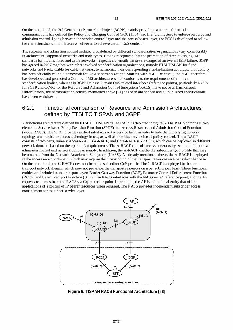
ETSI
ETSI TR 103 122 V1.1.1 (2012-11) 29
On the other hand, the 3rd Generation Partnership Project (3GPP), mainly providing standards for mobile communications has defined the Policy and Charging Control (PCC) [i.14] and [i.2] architecture to enforce resource and admission control. Lying between the service control layer and the access/bearer layer, the PCC is developed to follow the characteristics of mobile access networks to achieve certain QoS control.
The resource and admission control architectures defined by different standardization organizations vary considerably in architecture, supported networks and node types. Having recognized that the promotion of three diverging IMS standards for mobile, fixed and cable networks, respectively, entails the severe danger of an overall IMS failure, 3GPP has agreed in 2007 together with other involved standardization organizations, notably ETSI TISPAN for fixed networks and PacketCable for cable networks, to harmonize their corresponding standardization activities. This activity has been officially called "Framework for Gq'/Rx harmonization". Starting with 3GPP Release 8, the 3GPP therefore has developed and promoted a Common IMS architecture which conforms to the requirements of all three standardization bodies, whereas in 3GPP Release 7, main QoS-related interfaces (reference points), particularly Rx/Gx for 3GPP and Gq'/Re for the Resource and Admission Control Subsystem (RACS), have not been harmonized. Unfortunately, the harmonization activity mentioned above [i.1] has been abandoned and all published specifications have been withdrawn.
6.2.1 Functional comparison of Resource and Admission Architectures defined by ETSI TC TISPAN and 3GPP
A functional architecture defined by ETSI TC TISPAN called RACS is depicted in figure 6. The RACS comprises two elements: Service-based Policy Decision Function (SPDF) and Access-Resource and Admission Control Function (x-ouaiRACF). The SPDF provides unified interfaces to the service layer in order to hide the underlying network topology and particular access technology in use, as well as provides service-based policy control. The x-RACF consists of two parts, namely Access-RACF (A-RACF) and Core-RACF (C-RACF), which can be deployed in different network domains based on the operator's requirements. The A-RACF controls access networks by two main functions: admission control and network policy assembly. In addition, the A-RACF checks the subscriber QoS profile that may be obtained from the Network Attachment Subsystem (NASS). As already mentioned above, the A-RACF is deployed in the access network domain, which may require the provisioning of the transport resources on a per subscriber basis. On the other hand, the C-RACF does not check the subscriber QoS profile. The C-RACF is deployed in the core transport network domain, which may not provision the transport resources on a per subscriber basis. Three functional entities are included in the transport layer: Border Gateway Function (BGF), Resource Control Enforcement Function (RCEF) and Basic Transport Function (BTF). The RACS interfaces with the NASS via e4 reference point, and the AF requests resources from the RACS via Gq' reference point. In principle, the AF is a functional entity that offers applications of a control of IP bearer resources when required. The NASS provides independent subscriber access management for the upper service layer.
Rr
x-RACF
AF
SPDF
BGFRCEF
NASS
Re Ia
Gq’
Rd’, Ri’
Rqe4
Transport Processing Functions
RACS
BTF
Rf(Note 1)
(Note 2) (Note 2)
Rr
x-RACF
AF
SPDF
BGFRCEF
NASS
Re Ia
Gq’
Rd’, Ri’
Rqe4
Transport Processing Functions
RACS
BTF
Rf(Note 1)
(Note 2) (Note 2)
Figure 6: TISPAN RACS Functional Architecture [i.8]

ETSI
ETSI TR 103 122 V1.1.1 (2012-11) 30
Figure 7 shows overall logical architecture of 3GPP PCC (non-roaming) when SPR is used. In this architecture, the Policy and Charging Rules Function (PCRF) encompasses policy control decision and flow based charging control functionalities, providing network control regarding the service data flow detection, gating, QoS and flow based charging (except credit management) towards the Policy and Charging Enforcement Function (PCEF). The PCEF includes service data flow detection, policy enforcement and flow based charging functionalities. Located at the Gateway, the PCEF provides service data flow detection, user plane traffic handling, triggering control plane session management, QoS handling, and service data flow measurement as well as interaction with charging systems. The Subscription Profile Repository (SPR) stores information needed for subscription-based policies.
Gy
Gz
Subscription Profile Repository
(SPR)
Rx
AFSp
Gx
Offline Charging System (OFCS)Gateway
PCEF
Policy and Charging Rules Function (PCRF)
Gxx
BBERF
Online ChargingSystem (OCS)
Figure 7: Overall 3GPP PCC logical architecture (non-roaming) when SPR is used [i.14]
The main function of both TISPAN RACS and 3GPP PCC is to control the QoS of the network, but their architectures principally differ in the following aspects:
1) Control over Access Network: The TISPAN RACS controls the RCEF of access network via the A-RACF. For example, considering Asymmetric Digital Subscriber Line (ADSL) network, the RACS needs to control the access network node called in this case Digital Subscriber Line Access Multiplexer (DSLAM). Contrariwise, 3GPP PCC does not handle access networks, but focuses on IP Connectivity Access Network (IP-CAN), which can be set up in various access networks.
2) Gateway Node: In the PCC, the PCEF is responsible for handling QoS and policies; while 3GPP PCC is only responsible for resource authorization, and resource reservation is realized by the IP-CAN. Specifically speaking, the PCRF first computes the resource requirement of a service and authorizes the service to use resources. Then it sends related information to the PCEF. Upon receiving such information, the gateway node where the PCEF resides works with other nodes to set up an IP-CAN. Different kinds of access technologies have different IP-CAN signalling. On the other hand, both functions mentioned above are in TISPAN RACS handled by A-RACF and such gateway node in not available in RACS architecture, according to the [i.8].
ETSI
ETSI TR 103 122 V1.1.1 (2012-11) 31
3) Support of Access Technology: The typical feature of heterogeneous networks is the diversity of its underlying network access technologies. Among these technologies, the RACS R1 only supports fixed access, for instance, xDSL. In RACS R2, the access types have been extended, allowing the RACS to be applicable to any type of access. Anyhow, this new feature has to be extensively tested. In contrast to the previous case, 3GPP PCC is independent of access technology, so it is applicable to any access technology that complies with 3GPP IP-CAN definition, including General Packet Radio Service (GPRS), Wireless Local Area Network (WLAN) and Worldwide Interoperability for Microwave Access (WiMAX), Long Term Evolution (LTE).
4) Mobility Support: To guarantee the QoS in the case when the subscribers move, the resource and admission control system is required to support the mobility. Currently, the TISPAN RACS does not support the mobility. On the other hand, the PCC supports the mobility quite well.
5) Requirements for Terminals: 3GPP PCC requires its terminals to support QoS signalling. The signalling can be explicit. For instance, in the case of GPRS, the terminal should support Packet Data Protocol (PDP) context and the Universal Mobile Telecommunications System (UMTS) QoS parameter should be carried in the PDP context activation message. The signalling can be also implicit. For example, in WLAN, the bearer is an IPSec tunnel from the terminal to the Packet Data Gateway (PDG), so the terminal is just required to support IPSec. The TISPAN RACS does not have any strict requirements for terminal QoS signalling capability.
6) Support of Charging: This is an important function in resource control systems. The TISPAN RACS only supports offline charging. Moreover, the architecture and flow of the charging system are still under further study, and related signalling specifications have not been released. By contraries, the PCC supports several charging modes: online charging, offline charging and flow-based charging.
7) Network Address Translation (NAT)/Network Address Port Translation (NAPT): The TISPAN RACS has included NAT/NAPT into its scope. As a result, it supports these functions. The main mechanism of NAT/NAPT is covered by the BGF, which completes NAT/NAPT traversal under the control of the SPDF. NAT/NAPT is not covered by the scope of 3GPP PCC, so it has to be processed by other systems. For IMS, the NAT/NAPT traversal is handled by its access network gateway and the Proxy-Call Session Control Function (P-CSCF).
6.2.2 Comparison of Interfaces and Procedures of Resource and Admission Architectures defined by ETSI TC TISPAN and 3GPP
6.2.2.1 Comparison of Interfaces of Resource and Admission Architectures defined by ETSI TC TISPAN and 3GPP
In TISPAN RACS architecture, the main reference points are Gq', Rq, Re and Ia (see figure 6). Gq' is used for exchanging service-based policy information between the SPDF and the AF. Rq resides between the SPDF and the x-RACF and enables the SPDF to send QoS parameters to the x-RACF. Re is between the x-RACF and the RCEF, through which the A-RACF issues the policies of transport layer. Located between the SPDF and the BGF, Ia allows the BGF, under the control of the SPDF, to perform NAT and gating. On the other hand, the reference points involved in 3GPP PCC architecture mainly include Rx, Sp, Gy and Gz (see figure 7). Rx enables transport of application level session information from the AF to the PCRF. Such information is regarded by the PCRF as a part of inputs for PCC decision. Sp allows the PCRF to request subscription information from the SPR based on such parameters as subscriber ID. Gy resides between the Online Charging System (OCS) and the PCEF, allowing online credit control for service data flow-based charging. Gz lies between PCEF and OFCS and is used for transporting information required for offline charging.
As both Gq' and Rx are reference points connecting to the AF, their harmonization is of great significance. As mentioned at the beginning of clause 6.2, 3GPP and TISPAN have started research on Gq'/Rx harmonization. Unfortunately, this activity has been abandoned and all specifications have been withdrawn.

ETSI
ETSI TR 103 122 V1.1.1 (2012-11) 32
6.2.2.2 Comparison of Initial Admission and Reservation Procedures of Resource and Admission Architectures defined by ETSI TC TISPAN and 3GPP
Rx reference point (3GPP PCC) supports AF session setup procedure. When a new AF session is being established and media information for this AF session is available at the AF, the AF should open a session with the PCRF. It means that initial request message is sent via Rx reference point. Gq' reference point (TISPAN RACS) supports initial reservation procedure of a session. The comparison of the initial admission/reservation procedure is mainly made from the perspective of operations of related entities, i.e. SPDF (TISPAN RACS) and PCRF (3GPP PCC). Both the SPDF and the PCRF perform the following operations: execute policy decision according to the operator policy; open/close the gate of the BGF; and install policy/PCC rules on the BGF/PCEF upon receiving initial admission/reservation request from the AF.
Their different operations include following cases. The SPDF does not define transmission resources corresponding to IP session and subscriber IP address, and does not associate the request with subscription profile, which are both processed by the A-RACF. On the other hand, the PCRF determines IP-CAN session and bearer, and associates the request with subscription profile.
Moreover, both the subscriber's IP address and the globally unique address are sent over Gq' in TISPAN RACS architecture. The AF does not display service information related to negotiation phase on Gq'reference point, but indicates the valid period of reservation and supports hard-state/soft-state reservation. While in the case of 3GPP PCC, the AF displays service information related to negotiation phase on Rx reference point, but does not indicate the valid period of reservation and does not support hard-state/soft-state reservation.
6.2.2.3 Comparison of Modification Procedures of Resource and Admission Architectures defined by ETSI TC TISPAN and 3GPP
During the modification procedure over Rx reference point (3GPP PCC), the AF can modify following information of existing session: service information, indicator of service information negotiation and PCC rules. In the modification procedure over Gq' (TISPAN RACS), the following information of existing session can be modified by the AF: service information, gating control, transport policy rule and duration of reservation. Moreover, Gq' reference point supports a refresh of an existing session. However, Rx does not support this function.
6.2.2.4 Comparison of Termination Procedures of Resource and Admission Architectures defined by ETSI TC TISPAN and 3GPP
In 3GPP PCC architecture, when the AF receives an internal or external session release request, it sends a session termination message to the PCRF. The PCRF then identifies related AF session or IP-CAN session and bearer, instructs the PCEF to remove any PCC rule related to the IP streams of the AF session, and replies to the AF.
On the other hand, in the TISPAN RACS architecture, once session release is triggered, the AF sends a session termination request to the SPDF. If the related session has been set up, the SPDF should instruct the A-RACF to perform related operations and ask the BGF to close the gate. Upon receipt of acknowledgements from the A-RACF and the BGF, the SPDF replies to the AF.
7 Detailed Description of Shortcomings of Implementations
In total, three different perspectives of shortcoming of implementations have been investigated, namely shortcoming of interim solutions, problems related to migration of voice service to LTE and shortcoming of VoLTE Interoperability test event. The results of the investigation are presented in clauses below.
7.1 Interim Solutions Except of pure VoLTE that requires significant investment in network infrastructure (e.g. network wide IMS) and thus is considered as ubiquitous for upcoming years, the following interim solutions have been identified. Their principal shortcomings, benefits and principles are summarized in table 2 below.
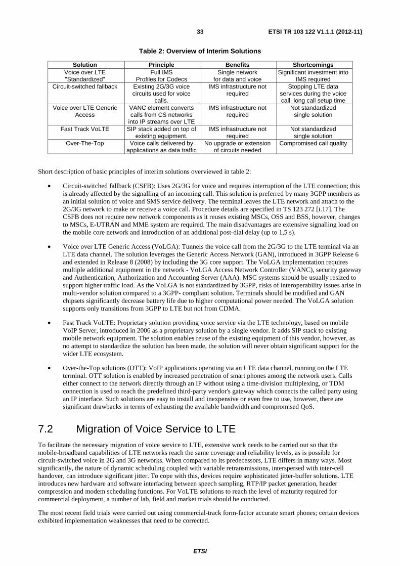
ETSI
ETSI TR 103 122 V1.1.1 (2012-11) 33
Table 2: Overview of Interim Solutions
Solution Principle Benefits Shortcomings Voice over LTE "Standardized"
Full IMS Profiles for Codecs
Single network for data and voice
Significant investment into IMS required
Circuit-switched fallback Existing 2G/3G voice circuits used for voice
calls.
IMS infrastructure not required
Stopping LTE data services during the voice call, long call setup time
Voice over LTE Generic Access
VANC element converts calls from CS networks
into IP streams over LTE
IMS infrastructure not required
Not standardized single solution
Fast Track VoLTE SIP stack added on top of existing equipment.
IMS infrastructure not required
Not standardized single solution
Over-The-Top Voice calls delivered by applications as data traffic
No upgrade or extension of circuits needed
Compromised call quality
Short description of basic principles of interim solutions overviewed in table 2:
• Circuit-switched fallback (CSFB): Uses 2G/3G for voice and requires interruption of the LTE connection; this is already affected by the signalling of an incoming call. This solution is preferred by many 3GPP members as an initial solution of voice and SMS service delivery. The terminal leaves the LTE network and attach to the 2G/3G network to make or receive a voice call. Procedure details are specified in TS 123 272 [i.17]. The CSFB does not require new network components as it reuses existing MSCs, OSS and BSS, however, changes to MSCs, E-UTRAN and MME system are required. The main disadvantages are extensive signalling load on the mobile core network and introduction of an additional post-dial delay (up to 1,5 s).
• Voice over LTE Generic Access (VoLGA): Tunnels the voice call from the 2G/3G to the LTE terminal via an LTE data channel. The solution leverages the Generic Access Network (GAN), introduced in 3GPP Release 6 and extended in Release 8 (2008) by including the 3G core support. The VoLGA implementation requires multiple additional equipment in the network - VoLGA Access Network Controller (VANC), security gateway and Authentication, Authorization and Accounting Server (AAA). MSC systems should be usually resized to support higher traffic load. As the VoLGA is not standardized by 3GPP, risks of interoperability issues arise in multi-vendor solution compared to a 3GPP- compliant solution. Terminals should be modified and GAN chipsets significantly decrease battery life due to higher computational power needed. The VoLGA solution supports only transitions from 3GPP to LTE but not from CDMA.
• Fast Track VoLTE: Proprietary solution providing voice service via the LTE technology, based on mobile VoIP Server, introduced in 2006 as a proprietary solution by a single vendor. It adds SIP stack to existing mobile network equipment. The solution enables reuse of the existing equipment of this vendor, however, as no attempt to standardize the solution has been made, the solution will never obtain significant support for the wider LTE ecosystem.
• Over-the-Top solutions (OTT): VoIP applications operating via an LTE data channel, running on the LTE terminal. OTT solution is enabled by increased penetration of smart phones among the network users. Calls either connect to the network directly through an IP without using a time-division multiplexing, or TDM connection is used to reach the predefined third-party vendor's gateway which connects the called party using an IP interface. Such solutions are easy to install and inexpensive or even free to use, however, there are significant drawbacks in terms of exhausting the available bandwidth and compromised QoS.
7.2 Migration of Voice Service to LTE To facilitate the necessary migration of voice service to LTE, extensive work needs to be carried out so that the mobile-broadband capabilities of LTE networks reach the same coverage and reliability levels, as is possible for circuit-switched voice in 2G and 3G networks. When compared to its predecessors, LTE differs in many ways. Most significantly, the nature of dynamic scheduling coupled with variable retransmissions, interspersed with inter-cell handover, can introduce significant jitter. To cope with this, devices require sophisticated jitter-buffer solutions. LTE introduces new hardware and software interfacing between speech sampling, RTP/IP packet generation, header compression and modem scheduling functions. For VoLTE solutions to reach the level of maturity required for commercial deployment, a number of lab, field and market trials should be conducted.
The most recent field trials were carried out using commercial-track form-factor accurate smart phones; certain devices exhibited implementation weaknesses that need to be corrected.

ETSI
ETSI TR 103 122 V1.1.1 (2012-11) 34
Basically all packet loss and jitter come from the LTE air interface. For call setup time, the target for VoLTE-to-VoLTE calls is to have shorter setup times than WCDMA to-WCDMA calls. The target setup time for VoLTE calls is to be below three seconds - the setup time for a WCDMA call is typically more than this. If the terminating UE is in an ongoing data session, the setup time for the VoLTE call will be significantly lower as no paging is needed.
In early launches of VoLTE, either in the form of market trials or commercial availability, the need to ensure a good user experience is paramount. Given the trend toward data-rich applications, voice now represents a smaller fraction of total device usage. It does, however, remain an essential capability, and user expectations for voice are very high. If voice services do not deliver the necessary level of quality and reliability, users will revert back to existing circuit-switched options or, in some cases, simply rely on over-the-top solutions. Clearly, the performance of the UE will play an even greater role for services provided over packet-switched networks than over circuit-switched. To meet VoLTE performance targets, JBM for the UE needs to meet specifications, and the delay contribution from other (post-decoder) UE internal processing outside the normal functionality should be negligible.
Efforts to validate VoLTE from an E2E perspective, have the key objective of retaining users. In Germany in early 2011, the first solution for wireless voice over IP using an LTE network was commercially deployed, validating many of the QoS and scheduler enablers that are required for VoLTE. The industry is progressing rapidly in terms of KPIs, measurement practices and, ultimately, the performance of early solutions.
In parallel, it is likely that LTE schedulers will become more sophisticated in terms of managing mixed voice and data traffic, while ensuring good battery performance.
7.3 VoLTE Interop Testing The first Voice over LTE (VoLTE) Interoperability 2011 event took place from September 12th-30th, 2011. The event was organised by the Multi-Service Forum (MSF) and backed by the GSMA.
Whitepaper MSF VoLTE Interoperability Event 2011, Website: http://www.msforum.org/interoperability/MSF_VoLTE%20_2011_WhitePaper.pdf, [online], latest accessed 20 June 2012
The VoLTE Interoperability Event 2011 test environment was based on:
1) Proving multivendor interoperability of Evolved Packet Core network nodes.
2) QoS control as an essential underpinning for services using PCC architecture and binding to the application layer in IMS.
3) Proving multivendor interoperability between IMS network nodes.
4) Proving VoLTE, including MMTel services via EPC and IMS, including interaction with the PCC architecture.
5) Roaming between EPC capable networks, including proving VoLTE and MMTel services for the roaming UE.
6) Proving VoLTE, including MMTel services, via the interconnect between IMS networks.
7) Intra-LTE Handover.
8) Robustness testing of EPC network nodes.
7.3.1 Description of Scenarios:
Basic Interoperability:
Attachment/Detachment of an LTE capable UE to the Evolved Packet Core via an eNodeB and creation/deletion of a default bearer with related Quality of Service applied utilising PCC architecture, IMS Registration, IMS Session establishment and teardown utilising a dedicated bearer with related Quality of Service applied utilising PCC architecture and MMTel Service Configuration and usage.
Roaming & Interconnect:
Roaming with Local Breakout in visited network (Visited P-CSCF) incorporating Attachment/Detachment of an LTE capable UE, IMS Registration, IMS Session establishment and teardown and MMTel Service Configuration and usage.

ETSI
ETSI TR 103 122 V1.1.1 (2012-11) 35
Interconnect between two UEs in their respective home PLMNs incorporating IMS Session establishment and teardown and MMTel Service usage.
Handover:
S1 and X2 based Handover between eNodeB's.
Robustness:
Core network traffic between S-GW, P-GW and IMS Core Network nodes.
7.3.2 Selected Results and Issues
Although basic interoperability was achieved, it was noted that implementations based on different versions of the Rel-8 Rx and Gx interfaces are not backwards compatible. Some implementations were discovered not to be fully compliant to 3GPP specifications, with missing mandatory functionality on various interfaces.
Several issues were encountered during the test execution of Basic Interoperability - VoLTE:
PCC Issues
On Gx and Rx interfaces, it was discovered that some implementations do not implement the Supported Features AVP. On both Rx and Gx interfaces, a Mandatory Supported Feature is introduced per 3GPP Release (e.g. Rel8). However it was discovered that Release 8 compliant implementations were not implementing this functionality. This resulted in an error code being returned to the originator of the message, with resultant Gx and Rx commands being rejected. The sender may optionally fall-back to an earlier 3GPP Release of the interface, however this would have resulted in Release 7 behaviour.
Backwards incompatibility between different versions of the same 3GPP Release was discovered on the Rx interface. Between version 8.4.0 and 8.6.0 of the Rx interface, backwards incompatible changes were introduced when the Specific-Action AVP was modified to introduce new events. As the Rx interface Supported Features introduces mandatory features per 3GPP Release, it lacks the granularity that is required to enable backwards compatibility between implementations based on the two different versions.
Mandatory AVP's were missing on the Gx and Rx interfaces in some implementations. The Bearer-Control-Mode and QoS-Information were missing on some implementations of the CCA of the Gx interface.
Precedence, Allocation-Retention-Priority and Rating-Group were missing on some implementations of the RAA of the Gx interface. The Auth-Application-ID was missing on some implementations of the AAR on the Rx interface.
Triggering of relevant Gx and Rx messages (CCR/AAR) were not performed by some implementations of P-GW and P-CSCF respectively. These resulted in lack of appropriate QoS being applied on the EPC bearer, and no session binding being performed in the PCRF between the IMS and EPC bearer.
IMS Issues
On the Cx interface, it was discovered that an HSS implementation did not implement the Supported Features AVP. For Release 8 compliant implementations, a mandatory Supported Feature (Alias Indication) is standardized. Non-support of this mandatory Supported Feature results in an error code being returned to the S-CSCF, with the SAR/SAA command being rejected - IMS Registration fails. The sender may optionally fallback to an earlier 3GPP Release of the interface, however this would have resulted in Release 7 behaviour.
The Sh interface was not supported on all implementations of HSS and MMTel Application Server. Whilst the Sh interface is optional, as user service information may be stored locally on the MMTel AS, it was discovered that some implementations of MMTel AS require the Sh interface to store user service information in the HSS. Without the support of the Sh interface, there is an interoperability issue between MMTel AS and HSS for some vendor combinations.
The Ut interface was not supported on all MMTel AS's in order to provide supplementary service configuration. Note that this is mandatory within GSMA PRD IR.92.
The Cx interface UAR/UAA command was found to fail in one configuration due to an incorrect implementation in the I-CSCF related to the setting of the Proxy-Bit in the command header. The Proxy-Bit is mandated to be set in both the request and answer messages, but was not being set by the I-CSCF.

ETSI
ETSI TR 103 122 V1.1.1 (2012-11) 36
3rd Party Registration requests were not being sent by all implementations of S-CSCF to the MMTel AS. The 3 rd party Registration is required to register the user on the MMTel AS and its availability for supplementary services.
The tests showed that there are ambiguities in the specifications for user authentication across the Ut interface. Specifically, it is not specified whether the username should be input as "user@domain" or simply as "user". Similarly, it is not specified whether username and password should be case sensitive, or case insensitive.
EPC Issues
Fragmentation issues were seen when the MTU size exceeded that specified by 3GPP for e.g. 1 500 octets in the transport network, providing a link MTU value of 1 358 octets to the MS as part of the IP configuration information from the network. During the IOT event, it was necessary to also reduce the size of the SIP INVITEs (e.g. by reducing the number of codecs being offered).
Transport Issues
SCTP was not initially supported by all DRA's, TCP was the transport protocol supported. 3GPP Diameter interfaces are based on SCTP for the transport protocol. This was resolved during the 3 week test period with SCTP being implemented.
The SCTP solution of one of the HSS's did not support dynamic local port allocation.
Difficulty was experienced when re-configuring the network components for testing the different multi-vendor configurations. The issue is mainly related to the test network configuration and the desire to test various different multivendor configurations; it is not seen as a major issue for network deployments.
7.3.3 Conclusions
However, MSF reports in the white paper mentioned above that:
"The event proved that VoLTE is a viable solution for providing voice services over LTE access technology, and can be deployed with roaming and interconnect functionality to provide equivalent service as CS-based voice services today."
Such statements raise the issue of what exactly has been tested, whether the cognitive interleaving teamwork (CITW) approach has been followed and what kind of understanding of the terms "Quality of Service" and "service" have been prevalent. A more detailed view into the scenarios of this interoperability event, e.g. scenario 1a, as depicted in figure 8 unveils that QoS of the media channel is not tested at all.
VoLTE Interoperability Event Testing Scenarios, Website: http://www.msforum.org/interoperability/MSF-VoLTE-SCN-001-FINAL.pdf, [online], latest accessed 20 June 2012.
Figure 8: Example of test scenario from VoLTE interop test
The following VoLTE test event had been announced by the MSF for October 2012, see:
MSF Press Release "RCS VoLTE Interoperability Event 2012, Website: http://www.msforum.org/pressroom/pr/RCS%20VoLTE%20PR%20Announcement%20_4_24_2012.pdf, [online], latest accessed 20 June 2012.
2.1.3 Test Cases 2.1.3.1 Scenario 1a The following tests will be executed in order to verify interoperabil ity of the indicated interfaces between different vendors. This scenario focuses on the verification of the functionality profiled within GSMA PRD IR.92.
• LTE UE Attach (IP-CAN Session Establishment) • Tracking Area Update • LTE UE Detach (IP-CAN Session Tear Down) • IMS UA Registration (via LTE UE) • IMS Voice Session Establishment (LTE UE to LTE UE) • IMS Voice Session Termination • MMTel Supplementary Service Interaction and Configuration

ETSI
ETSI TR 103 122 V1.1.1 (2012-11) 37
It is indicated that the specifications for the tests are provided in collaboration with ETSI INT.The event will focus on RCS and VoLTE in the following scenarios:
• Home/Single Network: In this scenario a single instance of the RCS VoLTE architecture will be created using components from different vendors. Testing will include attachment and detachment from the network, Tracking Area Update, IP-CAN session establishment, SIP registration (to IMS), SIP session establishment, interaction with IMS Multimedia Telephony, IMS Conversational Video Services and RCS services. This scenario focuses on testing interoperability of the functionality as profiled by GSMA PRDs IR.92 [i.28], IR.94 [i.29], IR.90 [i.27], IR.67 [i.25] and the RCS Services and Client Specification [i.30].
• Roaming & Interconnect: In this scenario, the local breakout model with visited P-CSCF and home operator applications is tested. The test set will be the same as for the home/single network case, plus some roaming specific tests to demonstrate the transfer of Policy Rules between home/visited networks, the usage of Diameter Routing Agents, and Session Border Controllers. This scenario focuses on testing interoperability of the functionality as profiled by GSMA PRDs IR.65 [i.24], IR 88 [i.26], IR.92 [i.28], IR.94 [i.29], IR.90 [i.27], IR.67 [i.25] and the RCS Services and Client Specification [i.30]. In addition, an IPX provides the interconnect network between the 2 PLMNs.
The event will also test:
• Non-LTE Access: In this scenario, the 'legacy' 3GPP access types of UMTS (UTRAN) and GSM/EDGE (GERAN) are used to interface to the EPC. The test set will include attachment, IMS registration and IMS session establishment and teardown.
• Handover: This scenario builds on the previous one and tests the number of handover scenarios. This will include intra-LTE handover (between eNodeBs, MME/S-GW relocation) and handover between LTE and legacy 3GPP (UMTS, GSM/EDGE) access.
• Inter-RAT Priority Call Handover: In this scenario the handover of priority voice calls between LTE and other RATs is tested. The scenario tests that voice calls originating as Multimedia Priority Service (MPS) VoLTE calls have relevant priority markings mapped properly when those calls are handed over to another Radio Access Technology (RAT) and the CS-domain and vice versa.
NOTE: Media quality itself is excluded.
8 Possible Solutions Possible solutions address different aspects as outlined in the following clauses.
8.1 Actions for Standards The actions are divided into the following parts.
8.1.1 Codec aspects
LTE network is built to offer higher capacity and reduced delay. With the migration to IP, LTE network is directly linked to IP network. Moreover, user equipment is no more only a mobile terminal but often a more sophisticated device. In order to limit the need of tandeming, the codec choices should not be limited to only codecs dedicated to mobile networks. MTSI client defined in [i.20] should have the possibility to access every codec supported by SIP. As soon as codec type has SIP-code point, MTSI client should support it.
Action point: appropriate standard TS 126 114 [i.20] should be extended accordingly.
In order to allow the use of such codecs. In addition, radio and packet core should be modified for example: different radio bearer and profile should be properly defined as well.
On the air interface, there should be an entity which is able to convey any SIP-supported codec.

ETSI
ETSI TR 103 122 V1.1.1 (2012-11) 38
In the case, when MTSI client remains limited to AMR [i.18] and AMR-WB [i.37] codecs, connections with other IP terminals would require change of codec at the border of the network, which means depacketisation, decoding, transcoding and repacketisation. All those actions are leading to lower quality and increase delay.
Another solution may be to force all networks to use codec dedicated to old mobile world, but in that case also, the quality may be lower. Moreover AMR and AMR-WB should not be seen as a single voice codec, in fact for both of them, it is a group of 8 or 9 different modes that were developed to be adapted to the 2G radio network (e.g. in order to cope with the fading). In 3G radio link, technology was changed making this ability useless. Within LTE network, another technology is used for radio link, AMR and AMR - WB may not be the best adapted codecs even if they are still needed for backward compatibility for existent 2G/3G networks. In that case, to avoid the risk of tandeming, it seems to be sufficient that the best mode is used.
In a case, when AMR and AMR-WB are still deployed, care should be taken whether the function "Error concealment of lost frames" defined in TS 126 091 [i.19] or TS 126 191 [i.22] are well adapted to the new use case, namely VoLTE involving new radio link and IP. Moreover relation between jitter buffer management and the function "Error concealment of lost frames" should be analysed as well.
To summarise the previous discussion, in principle, there are three possible solutions:
• tandeming;
• end-to-end connection based on AMR codec;
• using other codecs supported by IMS for end-to-end connections.
For example for AMR [i.18], there are eight different bit rates. For end-to-end, it seems to be sufficient that the best mode is deployed. If this is not achievable at air level, there might be a risk of tandeming. Tandeming generates extra delay.
When proposing some tandeming combinations introducing convenient amount of impairment, it is likely that IP connections with fixed networks will involve AMR [i.18] at 12,2 kb/s and G.711 or in wideband connections it will be AMR-WB [i.37] at 12,65 kb/s and G.722 at 64 kb/s. G.711 and G.722 [i.36] did not introduce significant delay on a top of the one due to packetisation.
8.1.2 Jitter-buffer Management Mechanisms
Jitter-buffer management mechanisms are currently not or at least not sufficiently standardized. Further study in this area is of critical importance.
8.1.3 Quality of Experience metrics
It is of basic importance that also in the context of LTE the extension from QoS to QoE parameters finds proper consideration in the near future. This applies to the entire chain of development, standardization, deployment and interop or field testing of delay sensitive applications.
As summarized in [i.31] network operators realized the technical excellence [based on QoS parameters, ed.] is not enough and even worse might be unnecessarily expensive. User-centric approach [based on additional QoE parameters, ed.] enables to target different parts of customer portfolio with different service quality levels, keeping both capex and opex conveniently optimal but even discovering faults that are not easily visible just using purely technical approach.
Since there are still no clear standards in place, which can support network operators in selecting those parameters in the QoE extension which they can successfully focus on, it is proposed to follow the approach of a Human Factors Extension to the Seven-Layer OSI Reference Model proposed by Bauer and Patrick [i.3] (see table 3). Basically, the three additional HCI (Human Computer Interface) layers capture the additional quality parameters introduced by the concept of QoE over QoS, whereas the classical 7 OSI layers are synonymous to classical QoS parameters.
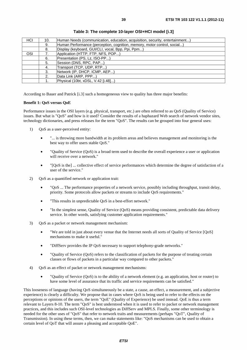
ETSI
ETSI TR 103 122 V1.1.1 (2012-11) 39
Table 3: The complete 10-layer OSI+HCI model [i.3]
HCI 10. Human Needs (communication, education, acquisition, security, entertainment...) 9. Human Performance (perception, cognition, memory, motor control, social...) 8. Display (keyboard, GUI/CLI, vocal, Bpp, Ppi, Ppm...)
OSI 7. Application (HTTP, FTP, NFS, POP...) 6. Presentation (PS, Lz, ISO-PP...) 5. Session (DNS, RPC, PAP...) 4. Transport (TCP, UDP, RTP...) 3. Network (IP, DHCP, ICMP, AEP...) 2. Data Link (ARP, PPP...) 1. Physical (10bt, xDSL, V.42 [i.48]...)
According to Bauer and Patrick [i.3] such a homogeneous view to quality has three major benefits:
Benefit 1: QoS versus QoE
Performance issues in the OSI layers (e.g. physical, transport, etc.) are often referred to as QoS (Quality of Service) issues. But what is "QoS" and how is it used? Consider the results of a haphazard Web search of network vendor sites, technology dictionaries, and press releases for the term "QoS". The results can be grouped into four general uses:
1) QoS as a user-perceived entity:
• "... is throwing more bandwidth at its problem areas and believes management and monitoring is the best way to offer users stable QoS."
• "Quality of Service (QoS) is a broad term used to describe the overall experience a user or application will receive over a network."
• "[QoS is the] ... collective effect of service performances which determine the degree of satisfaction of a user of the service."
2) QoS as a quantified network or application trait:
• "QoS ... The performance properties of a network service, possibly including throughput, transit delay, priority. Some protocols allow packets or streams to include QoS requirements."
• "This results in unpredictable QoS in a best-effort network."
• "In the simplest sense, Quality of Service (QoS) means providing consistent, predictable data delivery service. In other words, satisfying customer application requirements."
3) QoS as a packet or network management mechanism:
• "We are told in just about every venue that the Internet needs all sorts of Quality of Service [QoS] mechanisms to make it useful."
• "DiffServ provides the IP QoS necessary to support telephony-grade networks."
• "Quality of Service (QoS) refers to the classification of packets for the purpose of treating certain classes or flows of packets in a particular way compared to other packets."
4) QoS as an effect of packet or network management mechanisms:
• "Quality of Service (QoS) is to the ability of a network element (e.g. an application, host or router) to have some level of assurance that its traffic and service requirements can be satisfied."
This looseness of language (having QoS simultaneously be a state, a cause, an effect, a measurement, and a subjective experience) is clearly a difficulty. We propose that in cases where QoS is being used to refer to the effects on the perceptions or opinions of the users, the term "QoE" (Quality of Experience) be used instead. QoE is thus a term relevant to Layers 8-10. The term "QoS" is best understood when it is used to refer to packet or network management practices, and this includes such OSI-level technologies as DiffServ and MPLS. Finally, some other terminology is needed for the other uses of "QoS" that refer to network traits and measurements (perhaps "QoT", Quality of Transmission). In using these terms, then, we can make statements like: "QoS mechanisms can be used to obtain a certain level of QoT that will assure a pleasing and acceptable QoE".
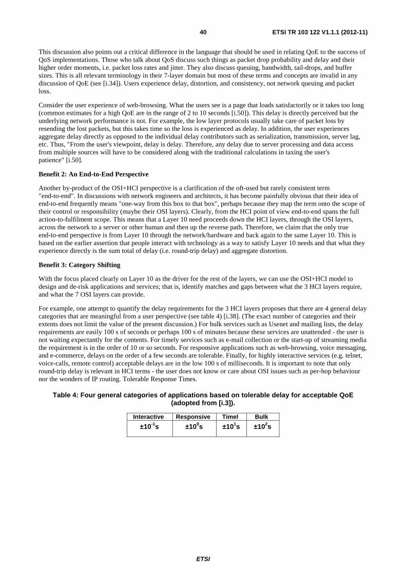
ETSI
ETSI TR 103 122 V1.1.1 (2012-11) 40
This discussion also points out a critical difference in the language that should be used in relating QoE to the success of QoS implementations. Those who talk about QoS discuss such things as packet drop probability and delay and their higher order moments, i.e. packet loss rates and jitter. They also discuss queuing, bandwidth, tail-drops, and buffer sizes. This is all relevant terminology in their 7-layer domain but most of these terms and concepts are invalid in any discussion of QoE (see [i.34]). Users experience delay, distortion, and consistency, not network queuing and packet loss.
Consider the user experience of web-browsing. What the users see is a page that loads satisfactorily or it takes too long (common estimates for a high QoE are in the range of 2 to 10 seconds [i.50]). This delay is directly perceived but the underlying network performance is not. For example, the low layer protocols usually take care of packet loss by resending the lost packets, but this takes time so the loss is experienced as delay. In addition, the user experiences aggregate delay directly as opposed to the individual delay contributors such as serialization, transmission, server lag, etc. Thus, "From the user's viewpoint, delay is delay. Therefore, any delay due to server processing and data access from multiple sources will have to be considered along with the traditional calculations in taxing the user's patience" [i.50].
Benefit 2: An End-to-End Perspective
Another by-product of the OSI+HCI perspective is a clarification of the oft-used but rarely consistent term "end-to-end". In discussions with network engineers and architects, it has become painfully obvious that their idea of end-to-end frequently means "one-way from this box to that box", perhaps because they map the term onto the scope of their control or responsibility (maybe their OSI layers). Clearly, from the HCI point of view end-to-end spans the full action-to-fulfilment scope. This means that a Layer 10 need proceeds down the HCI layers, through the OSI layers, across the network to a server or other human and then up the reverse path. Therefore, we claim that the only true end-to-end perspective is from Layer 10 through the network/hardware and back again to the same Layer 10. This is based on the earlier assertion that people interact with technology as a way to satisfy Layer 10 needs and that what they experience directly is the sum total of delay (i.e. round-trip delay) and aggregate distortion.
Benefit 3: Category Shifting
With the focus placed clearly on Layer 10 as the driver for the rest of the layers, we can use the OSI+HCI model to design and de-risk applications and services; that is, identify matches and gaps between what the 3 HCI layers require, and what the 7 OSI layers can provide.
For example, one attempt to quantify the delay requirements for the 3 HCI layers proposes that there are 4 general delay categories that are meaningful from a user perspective (see table 4) [i.38]. (The exact number of categories and their extents does not limit the value of the present discussion.) For bulk services such as Usenet and mailing lists, the delay requirements are easily 100 s of seconds or perhaps 100 s of minutes because these services are unattended - the user is not waiting expectantly for the contents. For timely services such as e-mail collection or the start-up of streaming media the requirement is in the order of 10 or so seconds. For responsive applications such as web-browsing, voice messaging, and e-commerce, delays on the order of a few seconds are tolerable. Finally, for highly interactive services (e.g. telnet, voice-calls, remote control) acceptable delays are in the low 100 s of milliseconds. It is important to note that only round-trip delay is relevant in HCI terms - the user does not know or care about OSI issues such as per-hop behaviour nor the wonders of IP routing. Tolerable Response Times.
Table 4: Four general categories of applications based on tolerable delay for acceptable QoE (adopted from [i.3]).
Interactive Responsive Timel Bulk
±10-1s ±100s ±101s ±102s

ETSI
ETSI TR 103 122 V1.1.1 (2012-11) 41
These delay categories are point estimators for acceptable QoE and prescribe what the OSI layers should provide in each case. If the lower layers cannot meet the upper layer requirements (because they are too slow, too bandwidth constrained, etc.), then alternate ways to address Layer 10 needs may be found by shifting the service to a less-demanding category (i.e. a rightward shift in table 3). Consider, for example, early 2,5G and 3G wireless cellular data networks (GPRS, 1XRTT). It is known that these networks will perform at or below the levels of dialup V.90 modems especially when mobile. Such networks will exhibit relatively low and variable bandwidth (10 Kbit/s to 60 Kbit/s), long round-trip delay (100 s of ms), and periods of disconnectivity due to cell reselection, radio fading, or obstruction. Therefore, common desktop office applications that are designed for networks with high bandwidth (10 s or 100 s of Mb/s), low round-trip delay (10 s of ms or less), and constant connectivity will not provide a high QoE in a wireless environment. Users will experience long delays in downloading e-mail and web pages, failed connections, very slow uploads, and perhaps interfaces that appear to freeze while waiting for data.
From the 10-Layer model perspective, one could say that such network performance (experienced as interface performance) is likely not to satisfy Layer 10, 9 and 8 requirements. However, a Layer 10 focus would cause one to ask "what need was the user trying to address" and how can this be achieved given what we know about performance of the OSI layers in this wireless case. If the Layer 10 needs was human-human communication, then the goal is to find solutions at Layers 9 and below to satisfy this need given the nature of the network. We might disqualify voice communication (interactive) due to excessive delay or packet loss and instead consider alternate methods to achieve the human-human communication. For example, a voice message rather than a voice call might suffice. As the Layer 8 and below resources become more constrained (terminal capabilities, network resources, etc.) one might consider chat, e-mail, or SMS (Short Messaging Service). In going from voice to messaging to SMS, we shifted the category and may have still satisfied the Layer 10 need (i.e. respected the semantics of the users' intent).
Thus, knowing the need and translating it into an application that can satisfy the need given human perception and network resource limitations can improve the likelihood of a higher QoE. Users may be willing to sacrifice some aspects of resolution (that is, they may tolerate distortion, low-resolution screens, low frame-rate, etc.) to gain economy or speed. In fact, relatively large quality reductions (in the colour, size, and spatial frequency domains) are well tolerated. When network characteristics will not provide a suitable transport to make a given application perform at high QoE, then the goal is to rework the application into something that will fit in the constraints of the OSI Layers, but address the Layer 10 requirements.
To summarize the previous discussion, it seems that the new OSI+HCI model (see table 3) provides a consistent language to help bridge different disciplines and serves as an aid in deciding in which discipline a concern falls. It also makes clear that a complete end-to-end perspective involves realizing that user experience is affected by aggregate network and application performance. Finally, the new OSI+HCI reference model provides a strategy for ensuring that the applications can operate satisfactorily within network limitations and still address the Layer 10 needs.HCI.
Such aspects need to be considered in the specification work of ETSI TC INT.
8.1.4 Framework for Gq'/Rx harmonization
As already described in clause 6.2, two resource and admission control solutions defined by 3GPP or ETSI are currently mainly deployed in the telecommunication networks. There are big functional differences as well as differences with regard to the interfaces and procedures involved in both architectures. In 2007, the activity called "Framework for Gq'/Rx harmonization" was created by 3GPP involving two additional standardization bodies, namely ETSI TISPAN and PacketCable. The main aim of this activity was to harmonize QoS-related interfaces (reference points), particularly Rx/Gx for 3GPP PCC and Gq'/Re for the Resource and Admission Control Subsystem (RACS). Unfortunately, this activity has been abandoned in 2009 and all published specifications have been withdrawn. It seems to be crucial to reopen this activity to define interactive interface supporting sufficient exchange of information between TISPAN RACS and 3 GPP PCC and harmonize the communication between two different resource and admission control solutions mainly deployed in current telecommunication networks to satisfy the subscribers' service experience. That is to say, the TISPAN RACS and the 3GPP PCC have to interact and negotiate with each other in order to finish the operations required for continuous QoS guarantee, for instance, resource reservation.
8.2 Actions for Implementations The actions are divided into the following parts.

ETSI
ETSI TR 103 122 V1.1.1 (2012-11) 42
8.2.1 Migration of voice service to LTE
Delay values achieved in trials and real implementations have to be carefully observed. As unexpected sources of additional delay can occur during the real operation, it is highly advisable to measure end-to end delay rather than summing partial delays introduced by different terminal and network elements. The measured delay have to be always evaluated according to the voice-related services that are considered or implemented in the network (voice only compared to video stream with browsing or data transfer, etc.) under conditions corresponding to the real operation. A special care has to be exercised to test all or at least most of possible scenarios when the voice service runs in parallel with other tasks causing additional load of available processing power or transmission conditions and bandwidth, especially combinations that cannot be influenced by the end-user (e.g. background automatic system and software update requests and downloads, etc.) In addition, a sufficient algorithms/techniques should be deployed in the networks in order to ensure continuous data sessions for incoming and outgoing voice/video calls. Finally, a Quality of Service perceived by the end-user should be carefully measured in trials and monitored in real implementations to ensure the best quality provided to the users.
8.2.2 VoLTE Interop testing
TC INT has begun to consider inclusion of QoS testing aspects into the specifications for forthcoming VoLTE interoperability events. It is important that appropriate QoS expertise is made available for such actions.
While this is a good starting point, the challenge of QoS in heterogeneous scenarios interconnecting current technologies with LTE may require additional effort in the future.
In figure 9 a typical LTE testing sequence has been exemplary extended by some possible QoS tests. While the black bullet items are the original test points of an LTE interoperability event today, the bullet items highlighted in red could constitute the extension by QoS test. In the example of figure 9 it would be measurements of delay, listening quality (MOS-LQOx) and of doubletalk capabilities. Details for such tests can be found in TS 103 737 to TS 103 740 [i.10], [i.11], [i.12] and [i.13].
• LTE UE Attach (IP-CAN Session Establishment) • Tracking Area Update • LTE UE Detach (IP-CAN Session Tear Down) • IMS UA Registration (via LTE UE) • IMS Voice Session Establishment (LTE UE to LTE UE) • One-way delay, measurement in both directions • MOS-LQOx, measurement in both directions • Voice channel behavior under double talk and background noise conditions • IMS Voice Session Termination • MMTel Supplementary Service Interaction and Configuration
Figure 9: Example of improved test scenario for VoLTE interop test
In order to evaluate the QoS as perceived by the user, such a test scenario should be developed in detail, considering in particular a suitable balance for all stakeholders between expected quality of QoS testing results and the required additional effort for such QoS testing.
Another option that should be further investigated beside the extension of interoperability test events with QoS testing, is the organization of a pure Speech and Video Quality Test Event for LTE.
8.3 Comparison of the proposed solutions with solutions used for other radio-link technologies (mainly UMTS)
Since in UMTS network Voice calls are mainly over circuit switched network, it is difficult to compare the proposed solutions with the ones that have been used to enhance the services in UMTS. Nevertheless, the solution adopted by UMTS to reduce the call setup time in 3G video telephony based on ITU-T Recommendation H.324 [i.42] might also be of some use when a similar problem occurs in LTE.
In UMTS network, Voice over IP was decided in case of a need of voice call during a data session. Unfortunately, network capacity did not allow sufficient quality to permit development of this service. Moreover, RoHC was not mandatory in 3G terminals, making the use of header compression impossible. Without header compression, the load of voice over IP service on the air interface is 3 or 4 times higher than the one generated by classical CS voice call.
ETSI
ETSI TR 103 122 V1.1.1 (2012-11) 43
On the other hand, the solutions proposed to enhance TS 126 114 [i.20] seem to be also helpful for voice over IP in UMTS. For example, by easing end-to-end connection using codec defined in SIP or also by permitting calls between fixed network and mobile network using the harmonisation of core networks.
9 Concluding remarks Deployment of delay-sensitive services (conversational voice, video telephony and messaging) over LTE is behind schedule.
As soon as multiple vendors make their LTE network and terminal equipment available, heterogeneous scenarios interconnecting existing technologies with LTE may require additional effort in terms of QoS/QoE testing.
ETSI TC STQ is invited to start a new work item on this topic; it is advisable to collaborate with TC INT on this topic and plan for related plug tests or pure LTE Speech Quality Test Events.

ETSI
ETSI TR 103 122 V1.1.1 (2012-11) 44
History
Document history
V1.1.1 November 2012 Publication