Embed Size (px)
Citation preview
ETSI TR 102 651 V1.1.1 (2009-06)
Technical Report
Broadband Radio Access Networks (BRAN);5 GHz high performance RLAN;Guide to the implementation of
Dynamic Frequency Selection (DFS)
ETSI
ETSI TR 102 651 V1.1.1 (2009-06) 2
Reference DTR/BRAN-00200015
Keywords access, broadband, radio, testing
ETSI
650 Route des Lucioles F-06921 Sophia Antipolis Cedex - FRANCE
Tel.: +33 4 92 94 42 00 Fax: +33 4 93 65 47 16
Siret N° 348 623 562 00017 - NAF 742 C
Association à but non lucratif enregistrée à la Sous-Préfecture de Grasse (06) N° 7803/88
Important notice
Individual copies of the present document can be downloaded from: http://www.etsi.org
The present document may be made available in more than one electronic version or in print. In any case of existing or perceived difference in contents between such versions, the reference version is the Portable Document Format (PDF).
In case of dispute, the reference shall be the printing on ETSI printers of the PDF version kept on a specific network drive within ETSI Secretariat.
Users of the present document should be aware that the document may be subject to revision or change of status. Information on the current status of this and other ETSI documents is available at
http://portal.etsi.org/tb/status/status.asp
If you find errors in the present document, please send your comment to one of the following services: http://portal.etsi.org/chaircor/ETSI_support.asp
Copyright Notification
No part may be reproduced except as authorized by written permission. The copyright and the foregoing restriction extend to reproduction in all media.
© European Telecommunications Standards Institute 2009.
All rights reserved.
DECTTM, PLUGTESTSTM, UMTSTM, TIPHONTM, the TIPHON logo and the ETSI logo are Trade Marks of ETSI registered for the benefit of its Members.
3GPPTM is a Trade Mark of ETSI registered for the benefit of its Members and of the 3GPP Organizational Partners. LTE™ is a Trade Mark of ETSI currently being registered
for the benefit of its Members and of the 3GPP Organizational Partners. GSM® and the GSM logo are Trade Marks registered and owned by the GSM Association.
ETSI
ETSI TR 102 651 V1.1.1 (2009-06) 3
Contents
Intellectual Property Rights ................................................................................................................................ 5
Foreword ............................................................................................................................................................. 5
1 Scope ........................................................................................................................................................ 6
2 References ................................................................................................................................................ 6
2.1 Normative references ......................................................................................................................................... 6
2.2 Informative references ........................................................................................................................................ 6
3 Definitions, symbols and abbreviations ................................................................................................... 8
3.1 Definitions .......................................................................................................................................................... 8
3.2 Symbols .............................................................................................................................................................. 8
3.3 Abbreviations ..................................................................................................................................................... 8
4 Purpose of the present document .............................................................................................................. 9
5 The importance of Spectrum Sharing ....................................................................................................... 9
6 A short history of "DFS" .......................................................................................................................... 9
6.1 Europe Spawns the Idea ..................................................................................................................................... 9
6.2 ITU-R Recommendation M.1652 ..................................................................................................................... 10
6.3 WRC-03 - ITU-R Resolution 229 .................................................................................................................... 10
6.4 DFS developments outside Europe: the example of the US ............................................................................. 10
7 Regulatory Requirements ....................................................................................................................... 11
7.1 Europe .............................................................................................................................................................. 11
7.1.1 Regulation ................................................................................................................................................... 11
7.1.1.1 ECC Decision ........................................................................................................................................ 11
7.1.1.2 EC Decision .......................................................................................................................................... 11
7.1.2 R&TTE Directive (Radio & Terminal Telecommunications Equipment Directive) .................................. 11
7.1.3 Harmonized Standard EN 301 893 ............................................................................................................. 12
7.2 US ..................................................................................................................................................................... 12
7.2.1 Regulation ................................................................................................................................................... 12
7.2.2 FCC Part 15.407 ......................................................................................................................................... 12
7.3 Other countries ................................................................................................................................................. 13
8 Types of Radars ...................................................................................................................................... 13
8.1 Maritime radars ................................................................................................................................................ 13
8.2 Meteorological radars ....................................................................................................................................... 13
8.3 Military radars .................................................................................................................................................. 13
9 RLAN Interference into Radar systems ................................................................................................. 14
9.1 Introduction ...................................................................................................................................................... 14
10 Radar Detection and Response - DFS Requirements ............................................................................. 15
10.1 Introduction ...................................................................................................................................................... 15
10.2 Radar Recognition Requirements ..................................................................................................................... 16
10.3 Radar detection considerations ......................................................................................................................... 17
10.3.1 Radar pulse properties and Detection Thresholds ....................................................................................... 17
10.3.2 Scan patterns ............................................................................................................................................... 18
10.3.3 Pulse patterns .............................................................................................................................................. 18
10.3.4 Radar Pulse Repetition Frequency (PRF) ................................................................................................... 18
10.3.4.1 Interleaved/Staggered PRF - Single Pulse based. .................................................................................. 19
10.3.4.2 Interleaved/Staggered PRF - Packet based. ........................................................................................... 19
10.3.5 Fixed Frequency versus Frequency Hopping .............................................................................................. 19
10.3.6 Radar RF bandwidth ................................................................................................................................... 20
11 DFS Efficiency ....................................................................................................................................... 21
11.1 Receiver performance ....................................................................................................................................... 21
11.2 Channel bandwidth considerations ................................................................................................................... 21
11.3 Traffic patterns ................................................................................................................................................. 21

ETSI
ETSI TR 102 651 V1.1.1 (2009-06) 4
11.4 Channel Occupancy .......................................................................................................................................... 21
12 DFS implementation in different RLAN configurations ........................................................................ 22
12.1 Access Point (master) with Clients (slaves) ..................................................................................................... 22
12.2 Point to Point Links .......................................................................................................................................... 22
12.3 Point to Multipoint Links and mesh networks .................................................................................................. 22
History .............................................................................................................................................................. 23

ETSI
ETSI TR 102 651 V1.1.1 (2009-06) 5
Intellectual Property Rights IPRs essential or potentially essential to the present document may have been declared to ETSI. The information pertaining to these essential IPRs, if any, is publicly available for ETSI members and non-members, and can be found in ETSI SR 000 314: "Intellectual Property Rights (IPRs); Essential, or potentially Essential, IPRs notified to ETSI in respect of ETSI standards", which is available from the ETSI Secretariat. Latest updates are available on the ETSI Web server (http://webapp.etsi.org/IPR/home.asp).
Pursuant to the ETSI IPR Policy, no investigation, including IPR searches, has been carried out by ETSI. No guarantee can be given as to the existence of other IPRs not referenced in ETSI SR 000 314 (or the updates on the ETSI Web server) which are, or may be, or may become, essential to the present document.
Foreword This Technical Report (TR) has been produced by ETSI Technical Committee Broadband Radio Access Networks (BRAN).
The basis for this work was a document submitted by the Wi-Fi Alliance Regulatory Task Group as an Associate Member of ETSI. The initial goal of this coordination was to advance global 5 GHz spectrum access through harmonization of RLAN regulations.
ETSI
ETSI TR 102 651 V1.1.1 (2009-06) 6
1 Scope Due to the scarcity of radio frequency spectrum, many radio systems have to share spectrum with other radio systems - in one form or another; 5 GHz Wireless Access Systems including Radio Local Area Networks (WAS/RLANs), also known as Wireless LANs, radio LANs, or RLANs, are no exception. Wireless LANs are allowed to operate in the 5 GHz bands which are also used by many radar systems.
The present document is intended to help the designers of Wireless LANs that operate in the 5 GHz frequencies understand the requirements for radar detection and avoidance. The performance requirements of such a mechanism, also known as DFS or Dynamic Frequency Selection, is further described in EN 301 893.
NOTE: It is advised to download the latest version of EN 301 893.
The present document deals only with the regulatory requirements and the philosophy under which they were issued. It does not provide design rules or example implementations. By avoiding such "blueprint" material, innovation among Wireless LAN designers is maintained and encouraged.
2 References References are either specific (identified by date of publication and/or edition number or version number) or non-specific.
• For a specific reference, subsequent revisions do not apply.
• Non-specific reference may be made only to a complete document or a part thereof and only in the following cases:
- if it is accepted that it will be possible to use all future changes of the referenced document for the purposes of the referring document;
- for informative references.
Referenced documents which are not found to be publicly available in the expected location might be found at http://docbox.etsi.org/Reference.
NOTE: While any hyperlinks included in this clause were valid at the time of publication ETSI cannot guarantee their long term validity.
2.1 Normative references The following referenced documents are indispensable for the application of the present document. For dated references, only the edition cited applies. For non-specific references, the latest edition of the referenced document (including any amendments) applies.
Not applicable.
2.2 Informative references The following referenced documents are not essential to the use of the present document but they assist the user with regard to a particular subject area. For non-specific references, the latest version of the referenced document (including any amendments) applies.
[i.1] Directive 1999/5/EC of the European Parliament and of the Council of 9 March 1999 on radio equipment and telecommunications terminal equipment and the mutual recognition of their conformity (R&TTE Directive).
ETSI
ETSI TR 102 651 V1.1.1 (2009-06) 7
[i.2] ETSI EN 301 893 (V1.2.3): "Broadband Radio Access Networks (BRAN); 5 GHz high performance RLAN; Harmonized EN covering essential requirements of article 3.2 of the R&TTE Directive".
[i.3] ETSI EN 301 893 (V1.3.1): "Broadband Radio Access Networks (BRAN); 5 GHz high performance RLAN; Harmonized EN covering essential requirements of article 3.2 of the R&TTE Directive".
[i.4] ETSI EN 301 893 (V1.4.1): "Broadband Radio Access Networks (BRAN); 5 GHz high performance RLAN; Harmonized EN covering essential requirements of article 3.2 of the R&TTE Directive".
[i.5] ETSI EN 301 893 (V1.5.1): "Broadband Radio Access Networks (BRAN); 5 GHz high performance RLAN; Harmonized EN covering essential requirements of article 3.2 of the R&TTE Directive".
[i.6] ETSI TR 102 439 (V1.1.1): "Broadband Radio Access Networks (BRAN); Test Report Template for testing to EN 301 893 (V1.3.1) (R&TTE)".
[i.7] ETSI TS 101 475 (V1.3.1): "Broadband Radio Access Networks (BRAN); HIPERLAN Type 2; Physical (PHY) layer".
[i.8] ITU-R Recommendation M.1652: "Dynamic frequency selection (DFS) in wireless access systems including radio local area networks for the purpose of protecting the radiodetermination service in the 5 GHz band".
[i.9] ITU-R Recommendation M.1638: "Characteristics of and protection criteria for sharing studies for radiolocation, aeronautical radionavigation and meteorological radars operating in the frequency bands between 5 250 and 5 850 MHz".
[i.10] ERC Decision (99)23 of 29 November 1999 on the harmonised frequency bands to be designated for the introduction of High Performance Radio Local Area Networks (HIPERLANs).
[i.11] ECC Decision(04)08 of 9 July 2004 on the harmonised use of the 5 GHz frequency bands for the implementation of Wireless Access Systems including Radio Local Area Networks (WAS/RLANs).
[i.12] ITU-R Resolution 229: "Use of the bands 5 150-5 250 MHz, 5 250-5 350 MHz and 5 470-5 725 MHz by the mobile service for the implementation of wireless access systems including radio local area networks".
[i.13] Memorandum Opinion and Order FCC 06-96: "Revision of Parts 2 and 15 of the Commission's Rules to Permit Unlicensed National Information Infrastructure (U-NII) devices in the 5 GHz band".
[i.14] Report and Order FCC 03-287: "In the matter of Revision of Parts 2 and 15 of the Commission's Rules to Permit Unlicensed National Information Infrastructure (U-NII) devices in the 5 GHz band".
[i.15] Commission Decision 2005/513/EC of 11 July 2005 on the harmonised use of radio spectrum in the 5 GHz frequency band for the implementation of wireless access systems including radio local area networks (WAS/RLANs).
[i.16] Commission Decision 2007/90/EC of 12 February 2007 amending Decision 2005/513/EC on the harmonised use of radio spectrum in the 5 GHz frequency band for the implementation of Wireless Access Systems including Radio Local Area Networks (WAS/RLANs).
[i.17] ITU-R Report M.2115: "Testing procedures for implementation of dynamic frequency selection".
[i.18] NPRM FCC 03-110: "In the Matter of Revision of Parts 2 and 15 of the Commission's Rules to Permit Unlicensed National Information Infrastructure (U NII) devices in the 5 GHz band".
[i.19] FCC Part 15.407: "Chapter I - Federal Communications Commission; Part 15 - Radio Frequency Devices - General technical requirements".
ETSI
ETSI TR 102 651 V1.1.1 (2009-06) 8
[i.20] IEEE 802.11: "IEEE Standard for Information Technology - Telecommunications and information exchange between systems - Local and Metropolitan networks - Specific requirements - Part 11: Wireless LAN Medium Access Control (MAC) and Physical Layer (PHY) specifications".
[i.21] IEEE 802.11a-1999 [ISO/IEC 8802-11:1999/Amd 1:2000(E)] (Supplement to IEEE Std 802.11, 1999 Edition): "Part 11: Wireless LAN Medium Access Control (MAC) and Physical Layer (PHY) specifications: High-speed Physical Layer in the 5 GHz Band".
3 Definitions, symbols and abbreviations
3.1 Definitions For the purpose of the present document, the terms and definitions given in EN 301 893 and the following apply:
HIPERLAN 2: High Performance Radio Local Area Network type 2 as described in e.g. TS 101 475 [i.7]
3.2 Symbols For the purposes of the present document, the following symbols apply:
dBi antenna gain in decibels relative to an isotropic antenna dBm dB relative to 1 milliwatt GHz GigaHertz Hz Hertz kHz kiloHertz MHz MegaHertz
3.3 Abbreviations For the purposes of the present document, the abbreviations given in EN 301 893 and the following apply:
DFS Dynamic Frequency Selection EIRP Equivalent Isotropically Radiated Power FCC Federal Communications Commission FH Frequency Hopping HIPERLAN High Performance Radio Local Area Network ITU International Telecommunications Union LAN Local Area Network MIMO Multiple-Input and Multiple-Output NTIA National Telecommunications and Information Administration pps pulses per second PRF Pulse Repetition Frequency R&TTE Radio and Telecommunications Terminal Equipment RADAR RAdio Detection And Ranging RF Radio Frequency RLAN Radio Local Area Network TCAM Telecommunication Conformity Assessment and Market surveillance committee TPC Transmitter Power Control WAS Wireless Access System
ETSI
ETSI TR 102 651 V1.1.1 (2009-06) 9
4 Purpose of the present document DFS is a sharing mechanism that will allow wireless LANs to share the 5 GHz frequency spectrum with various radar systems. DFS assures that the wireless LANs do not cause interference to the radar systems. EN 301 893, which is based on ITU-R Recommendation M.1652 [i.8] on DFS characteristics and parameters, provides detection threshold criteria and test patterns for DFS implementation. A DFS design that is able to meet all the test criteria may not necessarily detect all of the various radars in the real world.
The interaction between radar systems and wireless LANs is complex and the variation in radar characteristics is considerable. In order for DFS to be effective, it should be designed with a good understanding of these complexities and variations. The present document aims to facilitate that understanding and to help, indirectly assure that DFS designs meet their main purpose: effective detection and avoidance of co-channel operation with radar systems.
5 The importance of Spectrum Sharing Spectrum sharing is rapidly becoming the solution to the increasing demands for bandwidth of many different applications. In the case of wireless LANs, the initial air interfaces used licence exempt spectrum (often called unlicensed spectrum) in the 915 MHz (US only) and 2,4 GHz bands, in which various kinds of low power radio and non-radio devices are allowed to operate, including industrial, scientific and medical systems.
As wireless LANs developed into a major communications technology, the market demand for more spectrum became apparent. Regulators world-wide stepped up to that challenge and after a long period of preparation, agreed to allow wireless LANs to operate in the 5 GHz band.
This is only one example of how demand for spectrum was met by allowing two different systems, RLANs and radar systems, to share a given frequency range.
Essential to the success of sharing spectrum now and in the future is that the deployed systems meet the necessary technical requirements for sharing. These requirements include the detection of other primary spectrum users and avoiding interference to them. Establishing the sharing criteria may be a technically complex and involved process, but it is of the utmost importance that technical experts developing such techniques are aware of the wider issues of sharing and communicate well with spectrum managers and incumbents.
Failure of the sharing regime in a given band has potentially severe ramifications. Depending on the regulatory regime, national administrations may take appropriate measures to withdraw non-compliant equipment from the market or from service, prohibit its placing on the market or putting into service or restrict its free movement.
With the above in mind, it will be clear that, to secure access to shared spectrum for future technologies and applications, the DFS based sharing regime developed for the 5 GHz band has to succeed. Its success depends primarily on the effectiveness of the DFS implementations in products that are brought to market. The present document is intended to help designers of DFS based equipment, to achieve that objective.
6 A short history of "DFS"
6.1 Europe Spawns the Idea In 1999, the CEPT published ERC Decision (99)23 [i.10] on the harmonized frequency bands to be designated for the introduction of High Performance Radio Local Area Networks (HIPERLANs). In total 455 MHz of spectrum was allocated in Europe to these Hiperlans under more or less similar conditions (power levels, DFS, TPC), and this was later adopted as the basis for a global allocation at WRC-03. Devices operating in the band 5 150 MHz to 5 350 MHz were restricted to indoor use only and were limited to 200 mW EIRP. Outdoor operation was limited to 5 470 MHz to 5 725 MHz but they could use power levels up to 1 W EIRP. DFS and TPC were required when operating in 5 250 MHz to 5 350 MHz or 5 470 MHz to 5 725 MHz.

ETSI
ETSI TR 102 651 V1.1.1 (2009-06) 10
In the mean time ETSI had started the development of a Harmonized Standard that included the first DFS conformance specification ever developed. Initially, a standard was drafted specifically for HIPERLAN 2. That approach was changed in light of the success of the IEEE 802.11 [i.20] technologies and finally, in June 2003, ETSI sent the first version of the technology neutral harmonized standard, EN 301 893 [i.2], into national voting just prior to the start of the WRC-03.
6.2 ITU-R Recommendation M.1652 ITU-R Recommendation M.1652 [i.8] states that DFS is recommended in the 5 250 MHz to 5 350 MHz and 5 470 MHz to 5 725 MHz bands in order to eliminate potential RLAN interference to the radar systems. This mechanism is assumed to detect radar and to ensure that wireless LANs do not operate on those channels on which radars are operating.
This recommendation specifies the DFS detection and performance requirements but does not specify how DFS is to be implemented. However, it does define test procedures for validating DFS detection and performance.
6.3 WRC-03 - ITU-R Resolution 229 In 2003, after a preparation of many years, the International Telecommunications Union (ITU), at its World Radio Conference 2003 (WRC-03), agreed on a new frequency allocation on a co-primary basis to the mobile service for the implementation of wireless access systems including radio local area networks (WAS/RLANs) systems noting however that in the bands 5 250 MHz to 5 350 MHz and 5 470 MHz to 5 725 MHz, stations in the mobile service shall not claim protection from radiodetermination services. This was subject to technical and regulatory provisions included in the radio regulations, given in Resolution 229 [i.12] (WRC-03) that makes the Annex 1 of ITU-R Recommendation M.1652 [i.8] mandatory. This includes specific provisions to protect the incumbent systems; including military and weather radars.
6.4 DFS developments outside Europe: the example of the US In 2000, as the RLAN industry in the US was preparing to enter the 5 GHz spectrum market with products designed to the IEEE 802.11a [i.21] standard, manufacturers with worldwide distribution were concerned that Europe would restrict this band to HIPERLAN (High Performance Radio LAN) products as specified in ERC Decision (99)23 [i.10]. HIPERLAN was a specific RLAN technology developed by ETSI. The ERC Decision (99)23 [i.10] mandated two mechanisms to protect radars and other primary users of this band: DFS (Dynamic Frequency Selection) and TPC (Transmit Power Control). As a result, a project, P802.11 TGh, was started to add these mechanisms in the IEEE 802.11 [i.20] standard, with the assumption that if these additional regulatory requirements were met, global adoption of IEEE 802.11a-1999 [i.21] would be possible.
At that time the 5 GHz band for RLANs in the US was restricted to the 5 150 MHz to 5 250 MHz, 5 250 MHz to 5 350 MHz and 5 725 MHz to 5 825 MHz bands, but planning was already in the works for the 2003 meeting of the World Radiocommunication Conference, to add the 5 470 MHz to 5 725 MHz band. This made DFS even more important for the US market. Over the course of the next three years, the FCC, with the help of the wireless LAN industry and the NTIA, developed the DFS rules for the US.
The spectrum used within US Federal agencies is administered by an Executive Branch organization known as the NTIA (National Telecommunications and Information Administration). Spectrum allocated for use by US commercial and private citizens is administered by the FCC (Federal Communications Commission).
When considering opening the 5 GHz band for use by wireless LANs, the NTIA expressed a strong desire that products entering the new band would adequately protect US military radars. This requirement was the basis of the US position at the WRC-03 which developed the first DFS requirements document - ITU-R Recommendation M.1652 [i.8].
During the period 2003 to 2006, the FCC with the help of the wireless LAN industry and the NTIA, developed the DFS rules for the US.
Since ETSI BRAN developed the first 5 GHz Harmonized Standard (EN 301 893 (V1.2.3) [i.2]) in 2003, the DFS test specification included in this standard became the basis for the development of the FCC DFS test specification and other test specifications in other countries.
ETSI
ETSI TR 102 651 V1.1.1 (2009-06) 11
In the US, the FCC, NTIA and the wireless LAN industry collaborated to develop an extended set of DFS equipment test specifications that would ensure compliant equipment would provide protection of radar systems not previously addressed by the ITU-R Recommendation M.1652 [i.8]. The new requirements and the related radio certification process were released in July of 2006 (FCC-06-96 [i.13]) and are available on http://fjallfoss.fcc.gov/edocs_public/attachmatch/FCC-06-96A1.doc.
It can be noted that similar extensions on the radar detection requirements were incorporated by ETSI BRAN into EN 301 893(V1.3.1) [i.3]. EN 301 893 is the European Harmonized Standard for 5 GHz high performance RLANs.
7 Regulatory Requirements In addition to the world wide regulatory requirements agreed by the ITU-R (see clause 6), various national and regional regulatory regimes were developed and are further described in this clause.
7.1 Europe
7.1.1 Regulation
7.1.1.1 ECC Decision
As given already in clause 6.1, after the WRC-03, the CEPT (48 member countries) had revised the existing ERC Decision (99)23 [i.10] resulting in the "ECC Decision (04)08 [i.11] on the harmonized use of the 5 GHz frequency bands for the implementation of Wireless Access Systems including Radio Local Area Networks".
ECC decisions are implemented on a voluntary basis and as such only have a legal status in those countries where administrations have adopted them into their national regulations.
7.1.1.2 EC Decision
By mid of 2005, the European Commission published Commission Decision 2005/513/EC [i.15] requiring all EU member states (27 member states) to open the 5 GHz bands for the implementation of Wireless Access Systems including Radio Local Area Networks by 31 October 2005. The technical requirements contained in this Commission Decision are identical to those contained in ECC Dec(04)08 [i.11].
The Decision 2005/513/EC [i.15] was amended by EC Decision 2007/90/EC [i.16] of 12 February 2007.
It should be noted that the Decision 2005/513/EC [i.15] clearly specifies that the military and meteorological radars operating in the 5 250 MHz to 5 850 MHz band requires protection against harmful interference from WAS/RLAN.
7.1.2 R&TTE Directive (Radio & Terminal Telecommunications Equipment Directive)
The placing on the market and putting into service of radio equipment within the EU is regulated by the Directive 1999/5/EC [i.1] (R&TTE Directive). The Directive replaces the previous national Type Approval regimes by a Market Surveillance regime. The European Commission mandates European Standards Organizations (ESOs) to develop so-called Harmonized Standards. With the respect to the spectrum aspects of radio equipment, the relevant Harmonized Standards are developed by ETSI.
According to the R&TTE Directive, compliance with a Harmonized Standard allows the manufacturer to enjoy a presumption of conformity with the essential requirements of Directive 1999/5/EC [i.1] and as such they are allowed to place their products on the Community market.
NOTE: More information on the Directive 1999/5/EC [i.1] (R&TTE Directive) is available from the web pages from the European Commission on http://ec.europa.eu/enterprise/rtte/index_en.htm.
ETSI
ETSI TR 102 651 V1.1.1 (2009-06) 12
7.1.3 Harmonized Standard EN 301 893
Compliance with a Harmonized Standard allows the manufacturer to place his product on the community market, however it might not be sufficient to allow the use of the equipment. The regulation, Commission Decision 2005/513/EC [i.15], specifies that radars are to be protected, but only being capable of detecting the radar test signals included in EN 301 893 does not necessarily mean the device can detect any deployed radar. The final responsibility for providing the maximum level of protection to the radars rests with the manufacturer of the RLAN equipment who should develop the product in such a way that detection of radar signals is not restricted to just those signals specified in EN 301 893.
The first version of EN 301 893 (V1.2.3) [i.2], was published by ETSI in August 2003. That standard detailed 3 specific radar test signals and referred to ITU-R Recommendation M.1652 [i.8] that covers a wider range of radar signals.
EU administrations found equipment on the market that could detect the 3 specific radar test signals defined in the first version of this standard but not others. These were examples of equipment that were compliant with EN 301 893 (V1.2.3) [i.2] but not with the intent of the regulation which requires protection of radars. EN 301 893 (V1.3.1) [i.3] was produced in conjunction with the administrations of several EU member states including military experts and was published in August 2005 to address this issue. EN 301 893 (V1.3.1) [i.3] includes a wide range of radar test signals with pulse widths between 1 µs and 30 µs and PRF rates between 200 Hz and 4 000 Hz.
Subsequently EN 301 893 (V1.4.1) [i.4] has been published, to address an urgent need from industry to have a harmonized standard that also covers MIMO or other high throughput technologies and/or channel bonding.
At the end of 2006, regulators had reported the first interference cases (RLAN interference into weather radars) due to the fact that the DFS mechanism was disabled by the user or the operator of the network. EN 301 893 (V1.4.1) [i.4] now specifically includes the requirement that DFS controls (hardware or software) related to radar detection shall not be accessible to the user. It was clarified that it should not be possible for a user to disable DFS or to alter any of the DFS settings.
The above interference cases also led to testing performed by member states to verify the efficiency of DFS as implemented by different manufacturers. The results showed that some equipment, although being compliant with EN 301 893 (V1.3.1) [i.3], may not provide protection to some types of radars. During the same period new cases were reported where RLANs had caused interference into meteorological radars. A detailed investigation showed that radars using Staggered PRF and/or Pulse Widths below 1 µs are not necessarily protected by equipment compliant with EN 301 893 (V1.3.1) [i.3] or EN 301 893 (V1.4.1) [i.4] as the radar test signals included in those standards do not include these characteristics.
This issue was brought to the attention of the European Commission (TCAM) which after a detailed investigation instructed ETSI to further revise EN 301 893 (V1.4.1) [i.4] to detect radars employing staggered PRF and/or pulse widths below 1 µs. In addition a solution for the protection of meteorological radars employing complex scanning schemes (sometimes including receive only noise calibration scans) is also required for the band 5 600 MHz to 5 650 MHz. This resulted in the completion of EN 301 893 (V1.5.1) [i.5] by mid 2008.
7.2 US
7.2.1 Regulation
The FCC issued a Notice of Proposed Rulemaking (NPRM FCC 03-110) [i.18] in May of 2003 requiring DFS and TPC to operate a wireless LAN in the 5 470 MHz to 5 725 MHz band in the US, and added them also as a requirement in the 5 250 MHz to 5 350 MHz band. A Report and Order (FCC 03-287) [i.14] requiring DFS testing followed in November 2003, however the test parameters remained unspecified until June 2006. The Memorandum and Order FCC 06-96 [i.13] formally opened the 5 470 MHz to 5 725 MHz band in the US.
7.2.2 FCC Part 15.407
The US DFS rules reside in 47 CFR Part 15, subpart E (15.407) [i.19] - Unlicensed National Information Infrastructure Devices (http://www.fcc.gov/searchtools.html#rules). These are closely aligned with the ETSI rules, with some variations in the radar test patterns (see FCC-06-96 [i.13]).
ETSI
ETSI TR 102 651 V1.1.1 (2009-06) 13
7.3 Other countries Other countries have adopted regulations and conformance standards or specifications derived from those applicable in Europe or in the US.
8 Types of Radars The ITU-R Recommendation M.1638 [i.9] contains a list of typical characteristics of radars operating in the 5 GHz range.
8.1 Maritime radars These radars are found mostly on ships and along waterways where they are used to track and guide ships.
Typically, these radars operate at short to medium range and peak power levels in the range of 10 kW to 50 kW. Pulse patterns are typically straightforward with a PRF that lies between 800 pps and 4 000 pps and rotation speeds of up to 10 rotations per minute.
Maritime radars typically operate within the 9 GHz band.
8.2 Meteorological radars Meteorological radars operate in the 2 700 MHz to 2 900 MHz band (S-Band), the 5 470 MHz to 5 725 MHz band (C-Band) and the 9 300 MHz to 9 500 MHz band (X-Band). Each of these bands present a different set of advantages/drawbacks in relation with radar coverage, rain attenuation and data accuracy. The 5 470 MHz to 5 725 MHz band offers the best compromise for these parameters, further noting that, according to Radio Regulations Footnote 5.452, meteorological radars are mainly operating and more likely being deployed in the 5 600 MHz to 5 650 MHz band.
In Europe, among about 180 meteorological radars, 20 radars are operating in the 2 700 MHz to 2 900 MHz band (mainly southern Europe to overcome severe rain attenuation), whereas about 140 radars are deployed in the 5 600 MHz to 5 650 MHz band and 20 radars in the remaining parts of the 5 470 MHz to 5 725 MHz band.
Current meteorological radars make use of pulse widths between 0,5 µs and 2,5 µs. The typical PRF used ranges from 250 Hz to 1 200 Hz.
Meteorological radars use different pulse patterns, e.g. a fixed (constant) PRF, or a Single Pulse based Staggered PRF or Packet based Staggered/Interleaved PRF (see clause 10.3 for more details).
Meteorological radars typically operate according to a variety of scanning strategies. A given strategy may consist of multiple helical scan patterns each of which can use a different combination of pulse width, PRF (fixed or staggered), antenna rotation speed and antenna elevation. The total cycle time for a given strategy can vary from 5 min to 15 min. Depending on the type of radar, a scanning scheme may also include receive-only periods, often included in between 2 helical scan patterns. These are used for the noise calibration of the radar receiver with an antenna elevation angle typically between 15 degrees and 60 degrees.
Finally, the typical conducted peak power levels range from 100 kW to 250 kW (single or double polarization) and the antenna gain can be up to 45 dBi. The typical 3 dB antenna beam width is 0,9 degree or 1 degree while the rotation speed can vary from 1 to 6 rotations per minute.
8.3 Military radars In general fixed frequency military radars use emission schemes similar to weather radars and that also includes the use of staggered PRFs.
Military radars include rotating search radars that perform volumetric scanning much like civilian navigation radars as well as sector scanning radars and tracking radars.
ETSI
ETSI TR 102 651 V1.1.1 (2009-06) 14
In addition to fixed frequency operation, military radars also use frequency hopping techniques designed to avoid detection and interference. Therefore some combinations of Pulse Width, PRF, hopping rate, scanning rate and antenna beam width make these military radars difficult to detect.
It should also be noted that most of the military radars are transportable as they are mounted on trucks, ships, etc.
Due to national security considerations, some of the details of military radars are classified and therefore; specifics cannot be given here.
9 RLAN Interference into Radar systems
9.1 Introduction Radar is an acronym for RAdio Detection And Ranging. Radar stations may be fixed or mobile. Mobile radars in the 5 GHz bands are often military.
A radar system transmits a powerful set of narrow pulses into the environment. When these pulses strike an object, their energy is scattered and a small amount of that energy is bounced back towards the transmitting station. The radar's receiver then analyses the reflected signal received (e.g. power, time difference, frequency shift, etc.) to calculate distance and other information about the target.
Wireless LANs operating in the 5 GHz bands in the vicinity of radar systems can cause interference into the radar receivers if interference mitigation techniques such as DFS are not utilized which could lead to permanent co-channel operation with the radar. Because the RLAN energy is unrelated in time, frequency and phase to the radar, the RLAN signals look like noise sources.
Because of the very high gain of the typical radar antenna, only very little Wireless LAN energy is needed to cause interference to radar systems. Therefore wireless LANs within range (without DFS) will cause interference not only when they are within the main lobe of the radar antenna, but they may also cause interference when the wireless LAN is geographically close to the radar and seen by the sidelobes of the radar antenna.
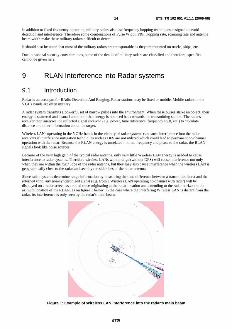
Since radar systems determine range information by measuring the time difference between a transmitted burst and the returned echo, any non-synchronized signal (e.g. from a Wireless LAN operating co-channel with radar) will be displayed on a radar screen as a radial trace originating at the radar location and extending to the radar horizon in the azimuth location of the RLAN, as on figure 1 below. In the case where the interfering Wireless LAN is distant from the radar, its interference is only seen by the radar's main beam.
Figure 1: Example of Wireless LAN interference into the radar's main beam
ETSI
ETSI TR 102 651 V1.1.1 (2009-06) 15
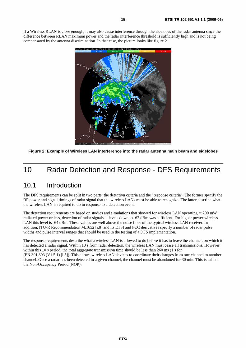
If a Wireless RLAN is close enough, it may also cause interference through the sidelobes of the radar antenna since the difference between RLAN maximum power and the radar interference threshold is sufficiently high and is not being compensated by the antenna discrimination. In that case, the picture looks like figure 2.
Figure 2: Example of Wireless LAN interference into the radar antenna main beam and sidelobes
10 Radar Detection and Response - DFS Requirements
10.1 Introduction The DFS requirements can be split in two parts: the detection criteria and the "response criteria". The former specify the RF power and signal timings of radar signal that the wireless LANs must be able to recognize. The latter describe what the wireless LAN is required to do in response to a detection event.
The detection requirements are based on studies and simulations that showed for wireless LAN operating at 200 mW radiated power or less, detection of radar signals at levels down to -62 dBm was sufficient. For higher power wireless LAN this level is -64 dBm. These values are well above the noise floor of the typical wireless LAN receiver. In addition, ITU-R Recommendation M.1652 [i.8] and its ETSI and FCC derivatives specify a number of radar pulse widths and pulse interval ranges that should be used in the testing of a DFS implementation.
The response requirements describe what a wireless LAN is allowed to do before it has to leave the channel, on which it has detected a radar signal. Within 10 s from radar detection, the wireless LAN must cease all transmissions. However within this 10 s period, the total aggregate transmission time should be less than 260 ms (1 s for (EN 301 893 (V1.5.1) [i.5]). This allows wireless LAN devices to coordinate their changes from one channel to another channel. Once a radar has been detected in a given channel, the channel must be abandoned for 30 min. This is called the Non-Occupancy Period (NOP).

ETSI
ETSI TR 102 651 V1.1.1 (2009-06) 16
Figure 3: Example state diagram of DFS behaviour
When choosing a new channel to operate on, a wireless LAN device must make sure that the channel is not occupied by a radar. This is done through a Channel Availability Check (CAC). When operating on a channel the wireless LAN must continue to monitor that channel for radar pulses so that it will detect (mobile) radars that come within its horizon or radars that are switched on while they are within the horizon of the wireless LAN.
Figure 3 is a simplified overview of a typical implementation of DFS.
For details of the DFS detection requirements, the reader is referred to ITU-R Recommendation M.1652 [i.8] and to ITU-R Report M.2115 [i.17] which does contain regional requirements developed for DFS.
It should be noted that, as mentioned in ITU-R Recommendation M.1652 [i.8], the ability of DFS to prevent interference rests on the large difference between the peak power output of a radar system and the low power output of the RLAN devices. If an RLAN detects a radar signal, it can cause interference to the radar. Vice versa: if the RLAN does not see a given radar, it will not cause interference into that radar.
10.2 Radar Recognition Requirements As noted above, radar signals are typically very strong signals. The power amplifiers of a radar produce pulses in the range of a few tens of Watts to a few hundreds of kiloWatts. These pulses are fed into a high gain antenna system that focuses the pulse energy into a narrow beam. Typical antenna gains are in the order of 40 dBi. The result is a radiated pulse power in the order of megaWatts. In spite of a strong transmit pulse, the return pulses are very weak. Hence, other energy generated in the same frequency band can be received by the radar at signal levels that can cause the radar unable to perform its intended function. As the same high gain antenna is used for transmitting and receiving, radar systems are very sensitive to interfering signals.
The frequencies occupied by the radar signal may be just a very narrow band, as in the case of certain weather radars, or they may occupy a wide range as in swept pulse (chirped) radars. In the latter the returned signal is un-swept to reduce the noise content and to improve the range precision. Yet other radars change their operating frequency according to some pattern in order to avoid detection and to improve noise performance. These radars are typically operated by the military.
ETSI
ETSI TR 102 651 V1.1.1 (2009-06) 17
Radar pulses travel in a straight line which means that buildings and other objects as well as the curvature of the earth produce radar "shadows" in which the radar signal is very weak. A radar beam creates a complex pattern of illuminated surfaces, much like a search light produces a pattern of light and dark areas. The dark areas correspond to no illumination by the radar. Reflections of buildings and other structures may also cause partial lighting of shadows so the same radar device may appear visible from different directions.
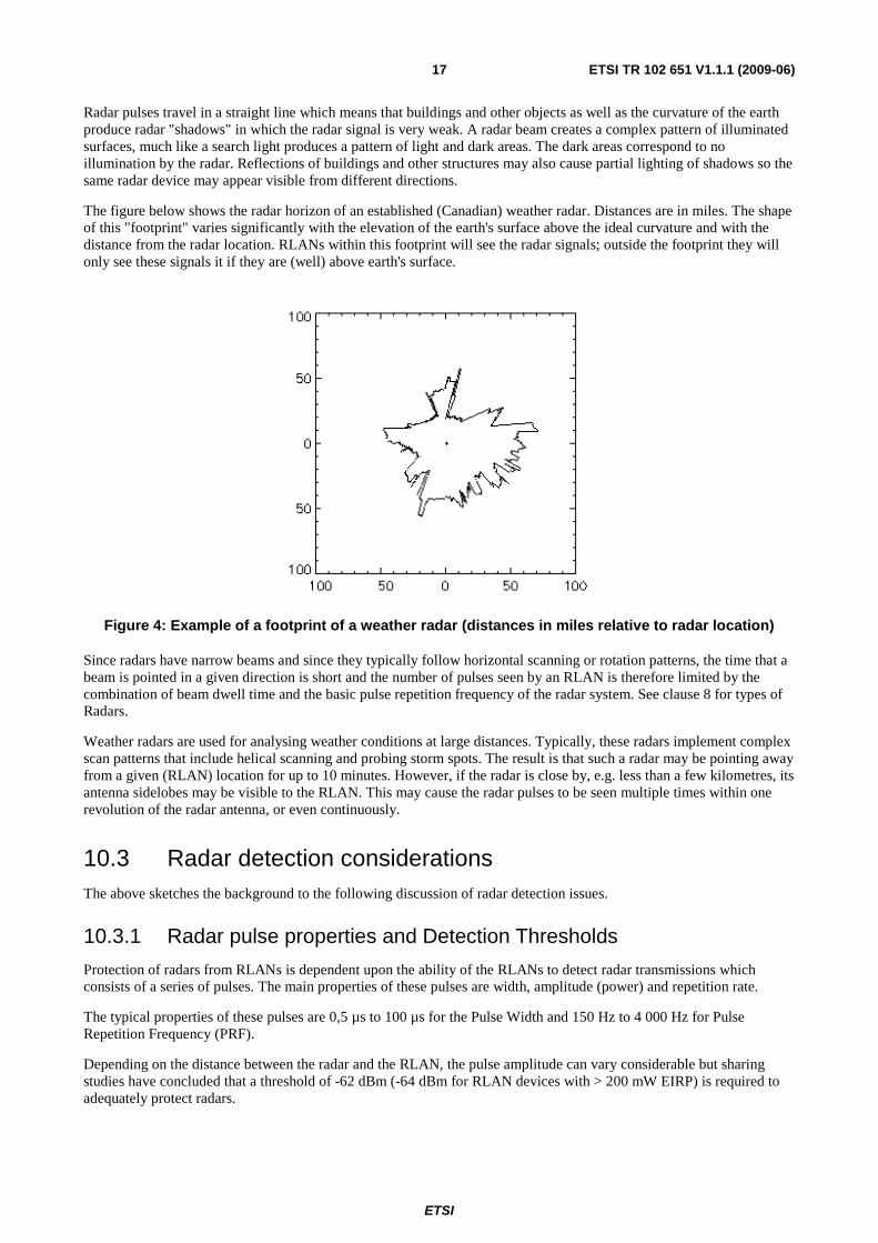
The figure below shows the radar horizon of an established (Canadian) weather radar. Distances are in miles. The shape of this "footprint" varies significantly with the elevation of the earth's surface above the ideal curvature and with the distance from the radar location. RLANs within this footprint will see the radar signals; outside the footprint they will only see these signals it if they are (well) above earth's surface.
Figure 4: Example of a footprint of a weather radar (distances in miles relative to radar location)
Since radars have narrow beams and since they typically follow horizontal scanning or rotation patterns, the time that a beam is pointed in a given direction is short and the number of pulses seen by an RLAN is therefore limited by the combination of beam dwell time and the basic pulse repetition frequency of the radar system. See clause 8 for types of Radars.
Weather radars are used for analysing weather conditions at large distances. Typically, these radars implement complex scan patterns that include helical scanning and probing storm spots. The result is that such a radar may be pointing away from a given (RLAN) location for up to 10 minutes. However, if the radar is close by, e.g. less than a few kilometres, its antenna sidelobes may be visible to the RLAN. This may cause the radar pulses to be seen multiple times within one revolution of the radar antenna, or even continuously.
10.3 Radar detection considerations The above sketches the background to the following discussion of radar detection issues.
10.3.1 Radar pulse properties and Detection Thresholds
Protection of radars from RLANs is dependent upon the ability of the RLANs to detect radar transmissions which consists of a series of pulses. The main properties of these pulses are width, amplitude (power) and repetition rate.
The typical properties of these pulses are 0,5 µs to 100 µs for the Pulse Width and 150 Hz to 4 000 Hz for Pulse Repetition Frequency (PRF).
Depending on the distance between the radar and the RLAN, the pulse amplitude can vary considerable but sharing studies have concluded that a threshold of -62 dBm (-64 dBm for RLAN devices with > 200 mW EIRP) is required to adequately protect radars.
ETSI
ETSI TR 102 651 V1.1.1 (2009-06) 18
The DFS detection threshold is defined with reference to a 0 dBi gain RLAN (receive) antenna. If the receive antenna gain is G dBi, the radar detection threshold should be set to -62 + G dBm or -64 + G dBm, depending on the EIRP of the device.
Regional variations exist for both characteristics of radars to be protected and the applicable DFS threshold level, therefore local regulations need to be checked.
10.3.2 Scan patterns
Radar systems employ scan patterns that vary depending on their application. Weather radars and some navigation radars may scan through 360 degrees whereas an air defence system may look only at a sector (90 degrees to 120 degrees). Tracking radars typically lock-on to their targets and therefore the direction of their antennas changes slower compared to a rotating radar. Weather radars typically employ a scanning scheme (often called a scanning strategy) consisting of multiple helical scan patterns with a total cycle time of as much as 15 min.
These differences in scan patterns lead to different bursts and burst interval periods seen by a RLAN at a certain position within the radar's footprint.
10.3.3 Pulse patterns
The typical "search" radar rotates regularly and as its beam sweeps over an object, that object is illuminated by a train of radar pulses. The Pulse Repetition Frequency (PRF) varies with the operating range of the radar: from 200 Hz for long range radars to 4 000 Hz for short range radars.
It is possible that more than one radar may be visible to an RLAN on the same RLAN channel. In this case the RLAN may see a variable pattern of pulses, some stronger than others, but as both radars will not be synchronized, there will be no time correlation between the pulse trains.
In addition, a single pulse from a given radar may be received more than once by the RLAN due to the effect of echo and/or reflections.
The detection probability for a given radar increases with the number of pulses seen by the RLAN during each rotation of the radar. So the radars which are easier to detect are those using either a wider antenna beam width, a higher PRF or a lower antenna rotation speed as all these factors will result in more pulses seen by the RLAN during each rotation.
10.3.4 Radar Pulse Repetition Frequency (PRF)
Radars make use of different emission schemes, presenting either constant PRF or staggered/interleaved PRF to increase their range and/or resolution.
A given PRF will result in:
• a maximum unambiguous distance (detection mode) above which there could be confusion between reflections from far away targets corresponding to Pulse N and reflections from nearby targets corresponding to pulse N+1;
• a maximum Nyquist Velocity (Doppler mode) above which there would be confusion on the burst to burst signal phase shift.
It should be noted that the lower the PRF, the higher the unambiguous distance but the lower the Nyquist velocity. As an example, for a PRF of 300 Hz, the unambiguous distance is about 500 km but the maximum velocity that can be detected is only 4 m/s. This means that for radars using Detection and Doppler Modes, the design of the emission schemes is a compromise between maximum distance and maximum velocity.
In order to improve the distance/velocity dilemma, most Doppler radars make use of Interleaved or Staggered PRF. An appropriate algorithm and carefully chosen PRF schemes remove any ambiguity. A high PRF value by nature results in a high velocity and low distance, but by using Staggered/Interleaved PRFs, the maximum distance is increased. Similarly, a low PRF value by nature results in a high distance but with a low velocity, but by using Staggered/Interleaved PRFs, the maximum velocity is increased.
As an example, using 3 interleaved PRF around 300 Hz would maintain an unambiguous distance around 500 km but would allow to increase the maximum velocity to 60 m/s.
ETSI
ETSI TR 102 651 V1.1.1 (2009-06) 19
There is no general nor typical PRF scheme. It is possible to change the PRF after each transmitted pulse and typically 2 or 3 different PRFs are used. It is also possible to change the PRF on a packet basis (some tens of pulses) and here only 2 different PRFs are used. The choice of a certain PRF scheme depends on the operational specifications and the technical constraints of the radar.
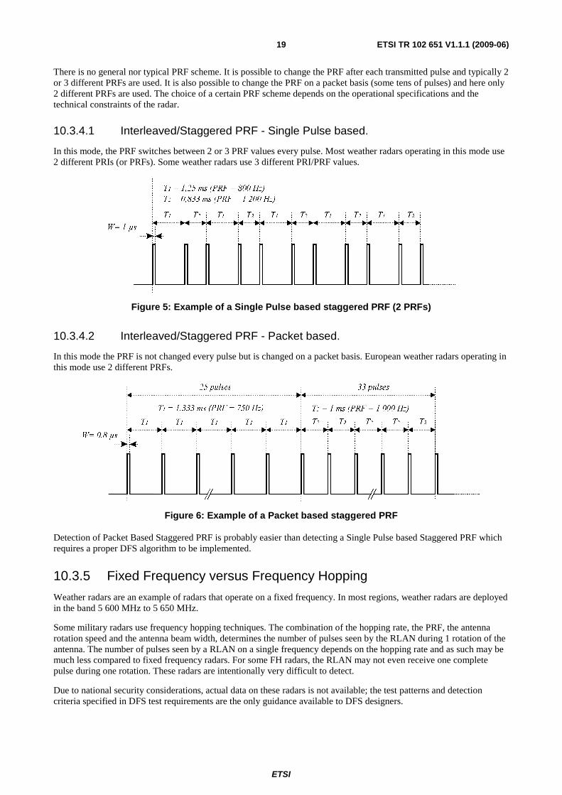
10.3.4.1 Interleaved/Staggered PRF - Single Pulse based.
In this mode, the PRF switches between 2 or 3 PRF values every pulse. Most weather radars operating in this mode use 2 different PRIs (or PRFs). Some weather radars use 3 different PRI/PRF values.
Figure 5: Example of a Single Pulse based staggered PRF (2 PRFs)
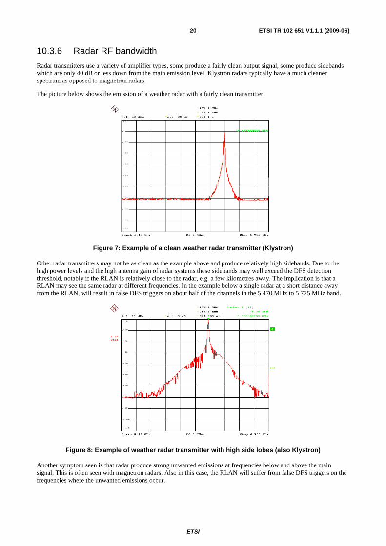
10.3.4.2 Interleaved/Staggered PRF - Packet based.
In this mode the PRF is not changed every pulse but is changed on a packet basis. European weather radars operating in this mode use 2 different PRFs.
Figure 6: Example of a Packet based staggered PRF
Detection of Packet Based Staggered PRF is probably easier than detecting a Single Pulse based Staggered PRF which requires a proper DFS algorithm to be implemented.
10.3.5 Fixed Frequency versus Frequency Hopping
Weather radars are an example of radars that operate on a fixed frequency. In most regions, weather radars are deployed in the band 5 600 MHz to 5 650 MHz.
Some military radars use frequency hopping techniques. The combination of the hopping rate, the PRF, the antenna rotation speed and the antenna beam width, determines the number of pulses seen by the RLAN during 1 rotation of the antenna. The number of pulses seen by a RLAN on a single frequency depends on the hopping rate and as such may be much less compared to fixed frequency radars. For some FH radars, the RLAN may not even receive one complete pulse during one rotation. These radars are intentionally very difficult to detect.
Due to national security considerations, actual data on these radars is not available; the test patterns and detection criteria specified in DFS test requirements are the only guidance available to DFS designers.
ETSI
ETSI TR 102 651 V1.1.1 (2009-06) 20
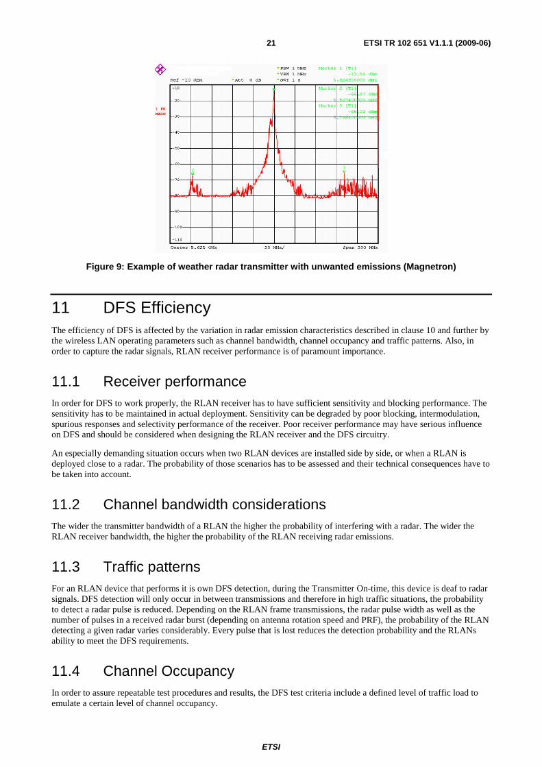
10.3.6 Radar RF bandwidth
Radar transmitters use a variety of amplifier types, some produce a fairly clean output signal, some produce sidebands which are only 40 dB or less down from the main emission level. Klystron radars typically have a much cleaner spectrum as opposed to magnetron radars.
The picture below shows the emission of a weather radar with a fairly clean transmitter.
Figure 7: Example of a clean weather radar transmitter (Klystron)
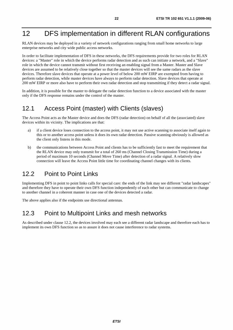
Other radar transmitters may not be as clean as the example above and produce relatively high sidebands. Due to the high power levels and the high antenna gain of radar systems these sidebands may well exceed the DFS detection threshold, notably if the RLAN is relatively close to the radar, e.g. a few kilometres away. The implication is that a RLAN may see the same radar at different frequencies. In the example below a single radar at a short distance away from the RLAN, will result in false DFS triggers on about half of the channels in the 5 470 MHz to 5 725 MHz band.
Figure 8: Example of weather radar transmitter with high side lobes (also Klystron)
Another symptom seen is that radar produce strong unwanted emissions at frequencies below and above the main signal. This is often seen with magnetron radars. Also in this case, the RLAN will suffer from false DFS triggers on the frequencies where the unwanted emissions occur.
ETSI
ETSI TR 102 651 V1.1.1 (2009-06) 21
Figure 9: Example of weather radar transmitter with unwanted emissions (Magnetron)
11 DFS Efficiency The efficiency of DFS is affected by the variation in radar emission characteristics described in clause 10 and further by the wireless LAN operating parameters such as channel bandwidth, channel occupancy and traffic patterns. Also, in order to capture the radar signals, RLAN receiver performance is of paramount importance.
11.1 Receiver performance In order for DFS to work properly, the RLAN receiver has to have sufficient sensitivity and blocking performance. The sensitivity has to be maintained in actual deployment. Sensitivity can be degraded by poor blocking, intermodulation, spurious responses and selectivity performance of the receiver. Poor receiver performance may have serious influence on DFS and should be considered when designing the RLAN receiver and the DFS circuitry.
An especially demanding situation occurs when two RLAN devices are installed side by side, or when a RLAN is deployed close to a radar. The probability of those scenarios has to be assessed and their technical consequences have to be taken into account.
11.2 Channel bandwidth considerations The wider the transmitter bandwidth of a RLAN the higher the probability of interfering with a radar. The wider the RLAN receiver bandwidth, the higher the probability of the RLAN receiving radar emissions.
11.3 Traffic patterns For an RLAN device that performs it is own DFS detection, during the Transmitter On-time, this device is deaf to radar signals. DFS detection will only occur in between transmissions and therefore in high traffic situations, the probability to detect a radar pulse is reduced. Depending on the RLAN frame transmissions, the radar pulse width as well as the number of pulses in a received radar burst (depending on antenna rotation speed and PRF), the probability of the RLAN detecting a given radar varies considerably. Every pulse that is lost reduces the detection probability and the RLANs ability to meet the DFS requirements.
11.4 Channel Occupancy In order to assure repeatable test procedures and results, the DFS test criteria include a defined level of traffic load to emulate a certain level of channel occupancy.
ETSI
ETSI TR 102 651 V1.1.1 (2009-06) 22
12 DFS implementation in different RLAN configurations RLAN devices may be deployed in a variety of network configurations ranging from small home networks to large enterprise networks and city wide public access networks.
In order to facilitate implementation of DFS in these networks, the DFS requirements provide for two roles for RLAN devices: a "Master" role in which the device performs radar detection and as such can initiate a network, and a "Slave" role in which the device cannot transmit without first receiving an enabling signal from a Master. Master and Slave devices are assumed to be relatively close together so that the master devices will see the same radars as the slave devices. Therefore slave devices that operate at a power level of below 200 mW EIRP are exempted from having to perform radar detection, while master devices have always to perform radar detection. Slave devices that operate at 200 mW EIRP or more also have to perform their own radar detection and stop transmitting if they detect a radar signal.
In addition, it is possible for the master to delegate the radar detection function to a device associated with the master only if the DFS response remains under the control of the master.
12.1 Access Point (master) with Clients (slaves) The Access Point acts as the Master device and does the DFS (radar detection) on behalf of all the (associated) slave devices within its vicinity. The implications are that:
a) if a client device loses connection to the access point, it may not use active scanning to associate itself again to this or to another access point unless it does its own radar detection. Passive scanning obviously is allowed as the client only listens in this mode.
b) the communications between Access Point and clients has to be sufficiently fast to meet the requirement that the RLAN device may only transmit for a total of 260 ms (Channel Closing Transmission Time) during a period of maximum 10 seconds (Channel Move Time) after detection of a radar signal. A relatively slow connection will leave the Access Point little time for coordinating channel changes with its clients.
12.2 Point to Point Links Implementing DFS in point to point links calls for special care: the ends of the link may see different "radar landscapes" and therefore they have to operate their own DFS function independently of each other but can communicate to change to another channel in a coherent manner in case one of the devices detected a radar.
The above applies also if the endpoints use directional antennas.
12.3 Point to Multipoint Links and mesh networks As described under clause 12.2, the devices involved may each see a different radar landscape and therefore each has to implement its own DFS function so as to assure it does not cause interference to radar systems.

ETSI
ETSI TR 102 651 V1.1.1 (2009-06) 23
History
Document history
V1.1.1 June 2009 Publication