Embed Size (px)
Citation preview
TECHNICAL REPORT
© The Broadband Forum. All rights reserved.
TR-061 Interfaces and System Configurations for ADSL:
Customer Premises Issue: 1.0
Issue Date: November 2003
Interfaces and System Configurations for ADSL: Customer Premises TR-061
September 2003 © The Broadband Forum. All rights reserved. 2
Notice The Broadband Forum is a non-profit corporation organized to create guidelines for broadband network system development and deployment. This Broadband Forum Technical Report has been approved by members of the Forum. This Broadband Forum Technical Report is not binding on the Broadband Forum, any of its members, or any developer or service provider. This Broadband Forum Technical Report is subject to change, but only with approval of members of the Forum. This Technical Report is copyrighted by the Broadband Forum, and all rights are reserved. Portions of this Technical Report may be copyrighted by Broadband Forum members. This Broadband Forum Technical Report is provided AS IS, WITH ALL FAULTS. ANY PERSON HOLDING A COPYRIGHT IN THIS BROADBAND FORUM TECHNICAL REPORT, OR ANY PORTION THEREOF, DISCLAIMS TO THE FULLEST EXTENT PERMITTED BY LAW ANY REPRESENTATION OR WARRANTY, EXPRESS OR IMPLIED, INCLUDING, BUT NOT LIMITED TO, ANY WARRANTY: (A) OF ACCURACY, COMPLETENESS, MERCHANTABILITY, FITNESS FOR A PARTICULAR
PURPOSE, NON-INFRINGEMENT, OR TITLE; (B) THAT THE CONTENTS OF THIS BROADBAND FORUM TECHNICAL REPORT ARE SUITABLE
FOR ANY PURPOSE, EVEN IF THAT PURPOSE IS KNOWN TO THE COPYRIGHT HOLDER; (C) THAT THE IMPLEMENTATION OF THE CONTENTS OF THE DOCUMENTATION WILL NOT
INFRINGE ANY THIRD PARTY PATENTS, COPYRIGHTS, TRADEMARKS OR OTHER RIGHTS. By using this Broadband Forum Technical Report, users acknowledge that implementation may require licenses to patents. The Broadband Forum encourages but does not require its members to identify such patents. For a list of declarations made by Broadband Forum member companies, please see http://www.broadband-forum.org. No assurance is given that licenses to patents necessary to implement this Technical Report will be available for license at all or on reasonable and non-discriminatory terms. ANY PERSON HOLDING A COPYRIGHT IN THIS BROADBAND FORUM TECHNICAL REPORT, OR ANY PORTION THEREOF, DISCLAIMS TO THE FULLEST EXTENT PERMITTED BY LAW (A) ANY LIABILITY (INCLUDING DIRECT, INDIRECT, SPECIAL, OR CONSEQUENTIAL DAMAGES UNDER ANY LEGAL THEORY) ARISING FROM OR RELATED TO THE USE OF OR RELIANCE UPON THIS TECHNICAL REPORT; AND (B) ANY OBLIGATION TO UPDATE OR CORRECT THIS TECHNICAL REPORT. Broadband Forum Technical Reports may be copied, downloaded, stored on a server or otherwise re-distributed in their entirety only, and may not be modified without the advance written permission of the Broadband Forum. The text of this notice must be included in all copies.

Interfaces and System Configurations for ADSL: Customer Premises TR-061
September 2003 © The Broadband Forum. All rights reserved. 3
Technical comments or questions about this Technical Report should be directed to:
Glen Cotant Excelsus Technologies Editors
Dave Allan Nortel Networks [email protected] Architecture &
Transport™ Working Group Chairs
Dave Thorne BT [email protected]
Interfaces and System Configurations for ADSL: Customer Premises TR-061
September 2003 © The Broadband Forum. All rights reserved. 4
TABLE OF CONTENTS
1 INTRODUCTION...................................................................................................................................................6
1.1 STATEMENT OF PROJECT....................................................................................................................................6 1.2 LIST OF ACRONYMS ...........................................................................................................................................6 1.3 THE BROADBAND FORUM REFERENCE MODEL................................................................................................6 1.4 CUSTOMER PREMISES SPECIFIC REFERENCE MODEL .......................................................................................7 1.5 RELEVANT WORK IN OTHER STANDARDS GROUPS OR FORUMS ......................................................................7
1.5.1 T1E1.4 .......................................................................................................................................................7 1.5.2 TR41 ..........................................................................................................................................................7 1.5.3 ATM Forum...............................................................................................................................................8 1.5.4 Various Home Networking Organizations ...............................................................................................8
2 TARGET APPLICATIONS AND SYSTEM IMPLICATIONS .......................................................................8
2.1 APPLICATIONS ...................................................................................................................................................8 2.2 SYSTEM IMPLICATIONS......................................................................................................................................8
3 ATU-R / SPLITTER INSTALLATION...............................................................................................................9
3.1 GENERAL CONSIDERATIONS..............................................................................................................................9 3.2 POTS SPLITTER .................................................................................................................................................9
3.2.1 Splitter Definition......................................................................................................................................9 3.2.2 POTS Splitter Characteristics ..................................................................................................................9
3.3 ATU-R / SPLITTER CONFIGURATIONS.............................................................................................................10 3.3.1 ATU-R adjacent to T.E. with Separate POTS Splitter ...........................................................................11 3.3.2 ATU-R adjacent to T.E. and Split POTS Splitter ...................................................................................13 3.3.3 ATU-R adjacent to T.E. and Distributed POTS Splitter ........................................................................15 3.3.4 ATU-R with integral POTS splitter adjacent to NID .............................................................................18 3.3.5 ATU-R with integral POTS splitter adjacent to T.E. .............................................................................20
3.4 ATU-R DEPLOYED WITHOUT POTS SERVICE..................................................................................................21
4 U-R, POTS-R, U-R2 INTERFACES...................................................................................................................22
4.1 WIRING CONSIDERATIONS...............................................................................................................................22 4.2 U-R OR U-R2...................................................................................................................................................22 4.3 POTS-R ...........................................................................................................................................................22
5 T-SM INTERFACE ..............................................................................................................................................23
5.1 SIGNAL SPECIFICATIONS..................................................................................................................................23 5.2 ISO INTERFACES AND CONNECTORS...............................................................................................................24 5.3 BASIC RJ45 INTERFACE...................................................................................................................................24
6 T-PDN INTERFACES - EXISTING PREMISES DISTRIBUTION NETWORKS.....................................26
6.1 BIT SYNCHRONOUS INTERFACES.....................................................................................................................26 6.2 ETHERNET 10BASET INTERFACE.....................................................................................................................26 6.3 HOMEPNA (ITU G.989)..................................................................................................................................26 6.4 CEBUS .............................................................................................................................................................26 6.5 IEEE 1394 (FIREWIRE) ....................................................................................................................................26 6.6 UNIVERSAL SERIAL BUS..................................................................................................................................27 6.7 ATM25 INTERFACE .........................................................................................................................................28 6.8 TR41 RESIDENTIAL GATEWAY........................................................................................................................28
7 ANNEX A THE BROADBAND FORUM SYSTEM REFERENCE MODEL ............................................29
8 ANNEX B PREMISE DISTRIBUTION NETWORK SHARING POTS/ADSL CABLING .....................31
8.1 SPLITTER CONFIGURATION..............................................................................................................................31 8.2 SPLITTERLESS CONFIGURATION ......................................................................................................................32
Interfaces and System Configurations for ADSL: Customer Premises TR-061
September 2003 © The Broadband Forum. All rights reserved. 5
List of Figures FIGURE 1 CUSTOMER PREMISES SPECIFIC REFERENCE MODEL .......................................................................................7 FIGURE 2. CONCEPTUAL ADSL ATU-R/SPLITTER INSTALLATION...................................................................................9 FIGURE 3. ATU-R ADJACENT TO T.E. AND SEPARATE POTS SPLITTER {LPF & HPF} .................................................11 FIGURE 4. ATU-R ADJACENT TO T.E. AND SEPARATE POTS SPLITTER {LPF & HPF} .................................................12 FIGURE 5. ATU-R (W/HPF) ADJACENT TO T.E. AND SPLIT POTS SPLITTER (LPF-ONLY).............................................13 FIGURE 6. ATU-R (W/HPF) ADJACENT TO T.E. AND SPLIT POTS SPLITTER (LPF-ONLY).............................................14 FIGURE 7. ATU-R (W/HPF) ADJACENT TO T.E. AND DISTRIBUTED (SPLIT) POTS SPLITTER (LPF-ONLY)...................15 FIGURE 8. ATU-R (W/HPF) ADJACENT TO T.E. AND DISTRIBUTED (SPLIT) POTS SPLITTER (LPF-ONLY)...................16 FIGURE 9. ATU-R (W/HPF) ADJACENT TO T.E. AND DISTRIBUTED (SPLIT) POTS SPLITTER (LPF-ONLY) AND
ISOLATION FUNCTION ..............................................................................................................................................17 FIGURE 10. ATU-R WITH INTEGRAL POTS SPLITTER (LPF & HPF) ADJACENT TO NID ...............................................18 FIGURE 11. ATU-R WITH INTEGRAL POTS SPLITTER (LPF & HPF) ADJACENT TO NID ...............................................19 FIGURE 12. ATU-R WITH INTEGRAL POTS SPLITTER (LPF & HPF) ADJACENT TO T.E.................................................20 FIGURE 13. ATU-R WITH INTEGRAL POTS SPLITTER (LPF & HPF) ADJACENT TO T.E.................................................21 FIGURE 14. RJ45 PLUG FOR THE T-SM INTERFACE..........................................................................................................25 FIGURE 15. A 1394 -BASED PREMISES DISTRIBUTION NETWORK ...................................................................................27 FIGURE 16 ATU-R USB SLAVE DEVICE CONNECTED TO A PC USB HOST .....................................................................28 FIGURE 17. AN INTEGRATED ATU-R USB HOST CONNECTING SEVERAL USB SLAVE DEVICES ....................................28 FIGURE 18. THE BROADBAND FORUM SYSTEM REFERENCE MODEL.............................................................................29 FIGURE 19. POTS/ADSL/HOMEPNA SPECTRUM ...........................................................................................................31 FIGURE 20. USE OF HOMEPNA WITH A NID SPLITTER ...................................................................................................31 FIGURE 21. EXAMPLE ISOLATOR .....................................................................................................................................32 FIGURE 22. USE OF HOMEPNA WITHOUT A NID SPLITTER ............................................................................................32
Interfaces and System Configurations for ADSL: Customer Premises TR-061
September 2003 © The Broadband Forum. All rights reserved. 6
1 Introduction
1.1 Statement of project This project intends to define electrical interfaces, connectorization, and wiring topology for ADSL customer premises installations. Where possible, technical information will be obtained by reference to existing specifications, and by liaison to technical standards groups. The work on this project is limited to addressing the interfaces necessary to support existing single user connections methods as well as multi-user connection methods utilizing Premises Distribution Networks (passive and active) for Bit Synchronous data, ATM data, and Packet data. Future work may be undertaken that addresses the use of emerging Premises Distribution Networks and the interfaces required to support them.
1.2 List of Acronyms AC Alternating Current ADSL Asymmetric Digital Subscriber Line AMI Alternate Mark Inversion ANSI American National Standards Institute ATM Asynchronous Transfer Mode ATU-C ADSL Transmission Unit at the Central Office End ATU-R ADSL Transmission Unit at the CPE End CD Compact Disk CPE Customer Premises Equipment CEBus Consumer Electronics Bus CSMA/CD Carrier Sense Multiple Access Collision Detect DVCR Digital Videocassette Recorder ETSI European Telecommunications Standards Institute HPF High Pass Filter HDB3 High Density Bipolar Three IEEE Institute of Electrical and Electronics Engineers I/O Input Output ISA Industry Standard Architecture (A PC bus standard) ISDN Integrated Services Digital Network ITU International Telecommunications Union ITU G.703 Physical/Electrical Characteristics of Hierarchical Digital Interfaces ITU G.704 Synchronous Frame Structures Used at Primary and Secondary Hierarchy Levels LPF Low Pass Filter MDSL Moderate speed Digital Subscriber Line NID Network Interface Device P1394 An IEEE Serial Bus Standard PC Personal Computer PCI Peripheral Component Interconnect PCMCIA Personal Computer Memory Card International Association POTS Plain Old Telephony Service PSTN Public Switched Telephone Network RJ45 10BASE-T Connector Standard for Connecting UTP Cabling TIA422 A Medium Range (typically up to 300m or more) Serial Data Transmission Standard SONET Syncronous Optical Network T1 A Telecommunications Standard Committee T1.403 Carrier to Customer Installation DS1 Metallic Interface T1.413-1995 ANSI Standard for ADSL modems T1E1.4 An ANSI committee for Interfaces, Network Power & Protection Digital Subscriber Loop Access TBD To be determined T.E. Terminal Equipment TPA P1394 signal link TPB P1394 signal link TR41 User Premises Telecom Requirements Committee TV Television UTP Unshielded Twisted Pair WT Working Text WT-003 Bit Syncronous Mode Working Text
1.3 The Broadband Forum Reference Model The Broadband Forum System Reference Model is described in Annex A.
Interfaces and System Configurations for ADSL: Customer Premises TR-061
September 2003 © The Broadband Forum. All rights reserved. 7
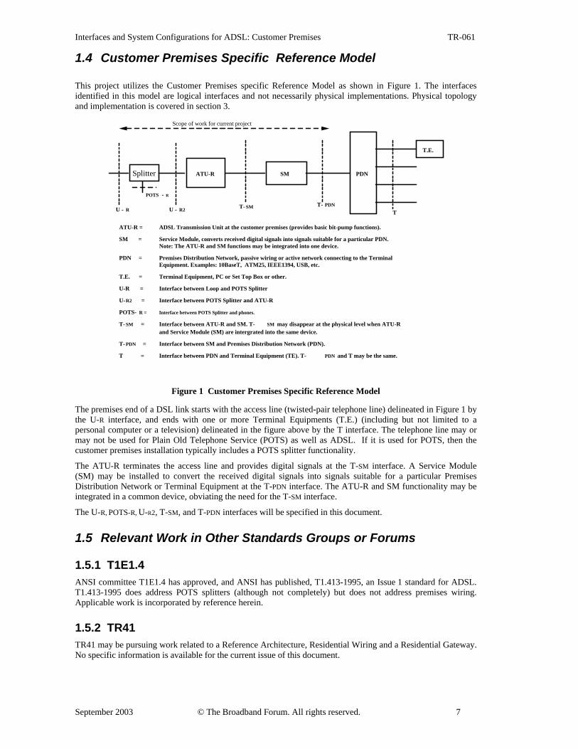
1.4 Customer Premises Specific Reference Model This project utilizes the Customer Premises specific Reference Model as shown in Figure 1. The interfaces identified in this model are logical interfaces and not necessarily physical implementations. Physical topology and implementation is covered in section 3.
ATU-R SM PDN
T.E.
ATU-R = ADSL Transmission Unit at the customer premises (provides basic bit-pump functions).
SM = Service Module, converts received digital signals into signals suitable for a particular PDN.Note: The ATU-R and SM functions may be integrated into one device.
PDN = Premises Distribution Network, passive wiring or active network connecting to the TerminalEquipment. Examples: 10BaseT, ATM25, IEEE1394, USB, etc.
T.E. = Terminal Equipment, PC or Set Top Box or other.
U-R = Interface between Loop and POTS Splitter
U-R2 = Interface between POTS Splitter and ATU-R
POTS- R = Interface between POTS Splitter and phones.
T- SM = Interface between ATU-R and SM. T- SM may disappear at the physical level when ATU-Rand Service Module (SM) are intergrated into the same device.
T- PDN = Interface between SM and Premises Distribution Network (PDN).
T = Interface between PDN and Terminal Equipment (TE). T- PDN and T may be the same.
T- SM T- PDNU - R2 T
Splitter
U - R
Scope of work for current project
POTS - R
Figure 1 Customer Premises Specific Reference Model
The premises end of a DSL link starts with the access line (twisted-pair telephone line) delineated in Figure 1 by the U-R interface, and ends with one or more Terminal Equipments (T.E.) (including but not limited to a personal computer or a television) delineated in the figure above by the T interface. The telephone line may or may not be used for Plain Old Telephone Service (POTS) as well as ADSL. If it is used for POTS, then the customer premises installation typically includes a POTS splitter functionality.
The ATU-R terminates the access line and provides digital signals at the T-SM interface. A Service Module (SM) may be installed to convert the received digital signals into signals suitable for a particular Premises Distribution Network or Terminal Equipment at the T-PDN interface. The ATU-R and SM functionality may be integrated in a common device, obviating the need for the T-SM interface.
The U-R, POTS-R, U-R2, T-SM, and T-PDN interfaces will be specified in this document.
1.5 Relevant Work in Other Standards Groups or Forums
1.5.1 T1E1.4 ANSI committee T1E1.4 has approved, and ANSI has published, T1.413-1995, an Issue 1 standard for ADSL. T1.413-1995 does address POTS splitters (although not completely) but does not address premises wiring. Applicable work is incorporated by reference herein.
1.5.2 TR41 TR41 may be pursuing work related to a Reference Architecture, Residential Wiring and a Residential Gateway. No specific information is available for the current issue of this document.
Interfaces and System Configurations for ADSL: Customer Premises TR-061
September 2003 © The Broadband Forum. All rights reserved. 8
1.5.3 ATM Forum The ATM Forum Residential Broadband (RBB) Group is working on a specification which includes a definition of an ATM based customer premises distribution network.
1.5.4 Various Home Networking Organizations The high speed ADSL connection is often shared between multiple T.E. within the Customer Premises. This distribution of the service is accomplished with a PDN (Premises Distribution Network). The SM can occur within the ATU-R or within the T.E. T.E. distribution is a growing technology and there are several organizations that have developed standards for products to network T.E. within the Customer Premise. Some of the organizations include:
• Home Phoneline Networking Alliance • HomePlug • WiFi / IEEE 802.11
2 Target Applications and System Implications
2.1 Applications The primary applications supported by ADSL are data communications, derived voice and video on demand. These applications require the transport of packet data, ATM data or bit synchronous data. The T-SM interface will depend on the application being supported.
In some cases, POTS service may not be offered in conjunction with ADSL, in which case the POTS splitter and POTS-R interface may not be needed.
2.2 System Implications Serving these applications will likely involve connecting more than one Terminal Equipment (T.E.) within a premises, with the second, third, or more terminal connected at some time after the installation of the ADSL modem itself. Furthermore, the installation and use of the ADSL modem should be as simple as possible, with the most reuse of existing wiring as possible, and with the least amount of trouble in migrating from one T.E. to another as possible.
Interfaces and System Configurations for ADSL: Customer Premises TR-061
September 2003 © The Broadband Forum. All rights reserved. 9
3 ATU-R / Splitter Installation
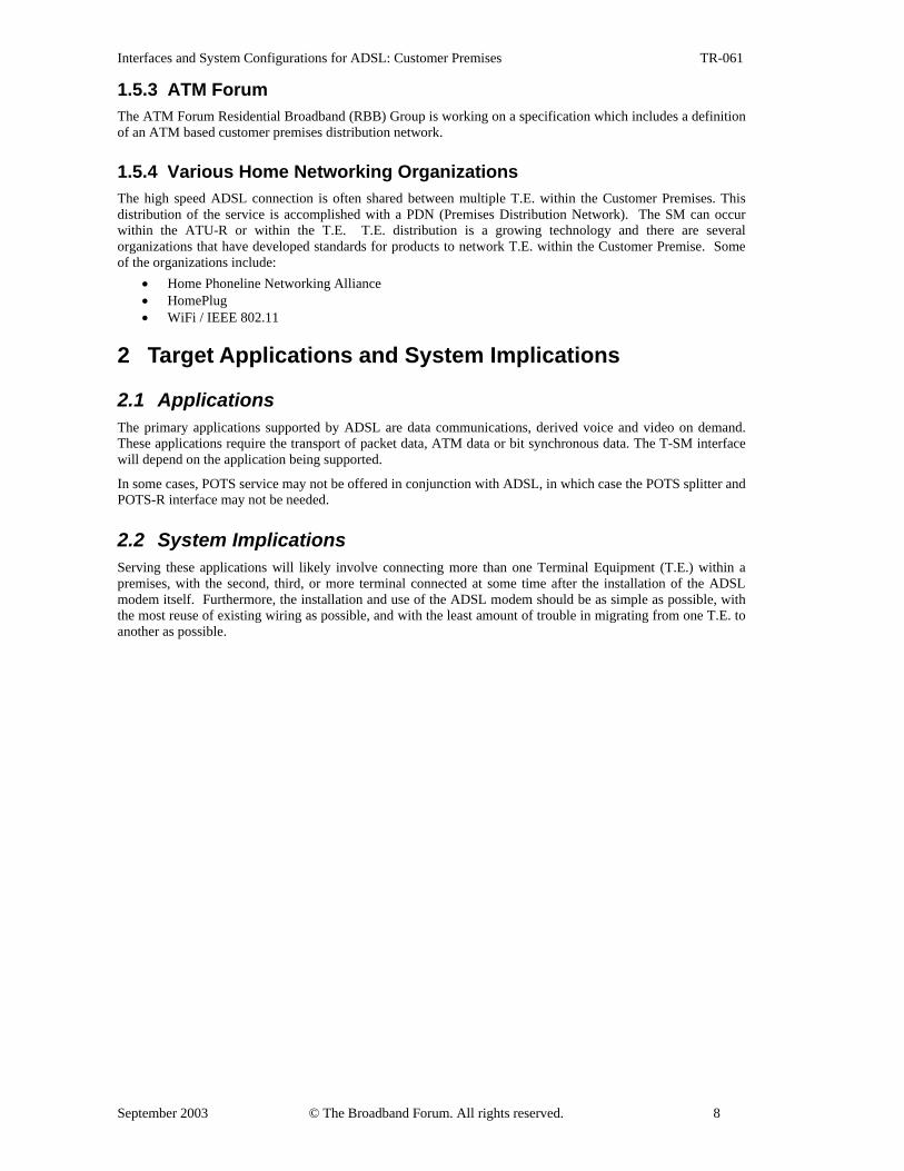
3.1 General Considerations Conceptually, the installation of an ADSL modem requires breaking an existing telephone line with active POTS service and attached telephones, inserting a POTS splitter, and then reattaching the premises side POTS wiring back to the POTS splitter (see Figure 2 which depicts both logical and physical attributes). Section 3.3 describes various POTS splitter topologies. Each subsection discusses scenarios that use and do not use the in-premise telephone wiring for the PDN in addition to carrying POTS.
In North America, a Network Interface Device (NID, usually comprising surge protectors) establishes the physical demarcation between network and customer premises. The ability to install the POTS Splitter prior to the ATU-R has particular appeal when the ATU-R is owned and installed by the user and not the network provider. This document only considers examples of installing the POTS splitter on the CPE side of the NID. Country specific installations of POTS splitters may need to address additional safety regulations.
NIDto Telco
Edge ofPremises
POTSSplitter
to Telco
Edge ofPremises
ATU-R
NID
Figure 2. Conceptual ADSL ATU-R/Splitter Installation
3.2 POTS Splitter
3.2.1 Splitter Definition The POTS splitter, for the purposes of this project, is considered to be the device or distributed devices that splits the POTS signals from the ADSL signals thus preventing the ADSL signals from reaching the telephone devices.
The POTS Splitter may be: • active or passive, comprise the LPF section and the HPF section or comprise the LPF section only • adjacent to the NID or housed within the NID • adjacent to each telephone device, adjacent to the ATU-R or integrated within the ATU-R The Low Pass Filter (LPF) section contains circuitry that passes POTS frequencies (approximately 0 to 4 kHz 1) to and from the telephone equipment and blocks the ADSL signal. The POTS Splitter (LPF only variation) may allow for the complete spectrum, including the ADSL signals (above approx. 20 kHz) to pass to the ATU-R.
In the case that a High Pass Filter (HPF) section is needed to prevent low frequency, high level POTS signals from entering the ATU-R front end components, the circuitry may be included in and be considered part of the ATU-R or the circuitry may be included as part of POTS Splitter (along with the LPF).
The ATU-R manufacturer should not assume that the HPF has been implemented external to his equipment. It is recommended that all manufactures of ATU-R equipment plan on explicitly implementing the appropriate HPF.
3.2.2 POTS Splitter Characteristics POTS Splitter characteristics will not be specified in this text. Instead the POTS Splitter is used as an existing system component and is shown along with the other system components such as ATU-R and wiring to comprise the configurations detailed in sections to follow. 1 Out of band signaling tones may need to be passed in some applications (this is outside the scope of this document).
Interfaces and System Configurations for ADSL: Customer Premises TR-061
September 2003 © The Broadband Forum. All rights reserved. 10
The standards listed below specify the loop conditions under which the splitter and ADSL must be able to operate without causing significant degradation to the POTS signal. POTS splitters are also specified in the following standards: - ANSI T1.413-1998 Annex E - ITU G.992.1 Annex E - ITU G.992.3 Annex E - ANSI T1.421 In-Line Filters - ETSI TR 101 728 V?
3.3 ATU-R / Splitter Configurations Various ATU-R/Splitter/Wiring configurations are discussed in the following sections.
• §3.3.1 - ATU-R adjacent to T.E. with Separate POTS Splitter • §3.3.2 - ATU-R adjacent to T.E. and Split POTS Splitter • §3.3.3 - ATU-R adjacent to T.E. and Distributed POTS Splitter • §3.3.4 - ATU-R with integral POTS splitter adjacent to NID • §3.3.5 - ATU-R with integral POTS splitter adjacent to T.E.
A brief introduction for each configuration is presented along with a figure depicting both logical and physical attributes (topology & implementation). This is followed by a list of advantages and disadvantages for each configuration. These advantages and disadvantages can be utilized in order to choose the configuration that best suits the needs of any particular deployment.
A suggested list of criteria is provided below that when used in conjunction with specific priorities or importance values (as determined by the provider) would allow a selection of the best configuration to be made for any particular ADSL system deployment.
Criteria: Type of Splitter - Active or Passive Equipment Ownership - Customer or Network owned Splitter, ATU-R Network demarcation point Failure effects of Splitter, ATU-R Installation Complexity Testing and Maintenance - Splitter, ATU-R Use of the in-premise wiring for the PDN
Interfaces and System Configurations for ADSL: Customer Premises TR-061
September 2003 © The Broadband Forum. All rights reserved. 11
3.3.1 ATU-R adjacent to T.E. with Separate POTS Splitter
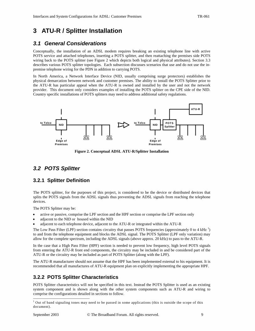
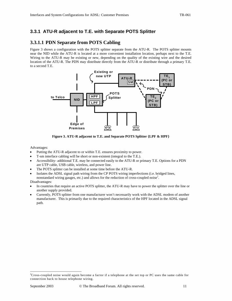
3.3.1.1 PDN Separate from POTS Cabling Figure 3 shows a configuration with the POTS splitter separate from the ATU-R. The POTS splitter mounts near the NID while the ATU-R is located at a more convenient installation location, perhaps next to the T.E. Wiring to the ATU-R may be existing or new, depending on the quality of the existing wire and the desired location of the ATU-R. The PDN may distribute directly from the ATU-R or distribute through a primary T.E. to a second T.E.
to Telco
Edge ofPremises
ATU-R
NID
POTSSplitter
LPF
HPF
Existing ornew UTP TE1
(PC orSTB)
PDN
TE2(PC orSTB)
SM
Figure 3. ATU-R adjacent to T.E. and Separate POTS Splitter {LPF & HPF}
Advantages: • Putting the ATU-R adjacent to or within T.E. ensures proximity to power. • T-sm interface cabling will be short or non-existent (integral to the T.E.). • Accessibility- additional T.E. may be connected easily to the ATU-R or primary T.E. Options for a PDN
are UTP cable, USB cable, wireless, and power line. • The POTS splitter can be installed at some time before the ATU-R. • Isolates the ADSL signal path wiring from the CP POTS wiring imperfections (i.e. bridged lines,
nonstandard wiring gauges, etc.) and allows for the reduction of cross-coupled noise2. Disadvantages: • In countries that require an active POTS splitter, the ATU-R may have to power the splitter over the line or
another supply provided. • Currently, POTS splitter from one manufacturer won’t necessarily work with the ADSL modem of another
manufacturer. This is primarily due to the required characteristics of the HPF located in the ADSL signal path.
2Cross-coupled noise would again become a factor if a telephone at the set top or PC uses the same cable for connection back to house telephone wiring.
Interfaces and System Configurations for ADSL: Customer Premises TR-061
September 2003 © The Broadband Forum. All rights reserved. 12
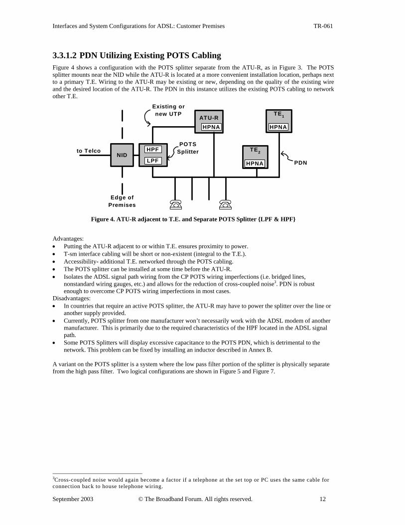
3.3.1.2 PDN Utilizing Existing POTS Cabling Figure 4 shows a configuration with the POTS splitter separate from the ATU-R, as in Figure 3. The POTS splitter mounts near the NID while the ATU-R is located at a more convenient installation location, perhaps next to a primary T.E. Wiring to the ATU-R may be existing or new, depending on the quality of the existing wire and the desired location of the ATU-R. The PDN in this instance utilizes the existing POTS cabling to network other T.E.
to Telco
Edge ofPremises
ATU-R
NID
POTSSplitter
LPF
HPF
Existing ornew UTP TE1
TE2
HPNA
HPNA
HPNA
PDN
Figure 4. ATU-R adjacent to T.E. and Separate POTS Splitter {LPF & HPF}
Advantages: • Putting the ATU-R adjacent to or within T.E. ensures proximity to power. • T-sm interface cabling will be short or non-existent (integral to the T.E.). • Accessibility- additional T.E. networked through the POTS cabling. • The POTS splitter can be installed at some time before the ATU-R. • Isolates the ADSL signal path wiring from the CP POTS wiring imperfections (i.e. bridged lines,
nonstandard wiring gauges, etc.) and allows for the reduction of cross-coupled noise3. PDN is robust enough to overcome CP POTS wiring imperfections in most cases.
Disadvantages: • In countries that require an active POTS splitter, the ATU-R may have to power the splitter over the line or
another supply provided. • Currently, POTS splitter from one manufacturer won’t necessarily work with the ADSL modem of another
manufacturer. This is primarily due to the required characteristics of the HPF located in the ADSL signal path.
• Some POTS Splitters will display excessive capacitance to the POTS PDN, which is detrimental to the network. This problem can be fixed by installing an inductor described in Annex B.
A variant on the POTS splitter is a system where the low pass filter portion of the splitter is physically separate from the high pass filter. Two logical configurations are shown in Figure 5 and Figure 7.
3Cross-coupled noise would again become a factor if a telephone at the set top or PC uses the same cable for connection back to house telephone wiring.
Interfaces and System Configurations for ADSL: Customer Premises TR-061
September 2003 © The Broadband Forum. All rights reserved. 13
3.3.2 ATU-R adjacent to T.E. and Split POTS Splitter
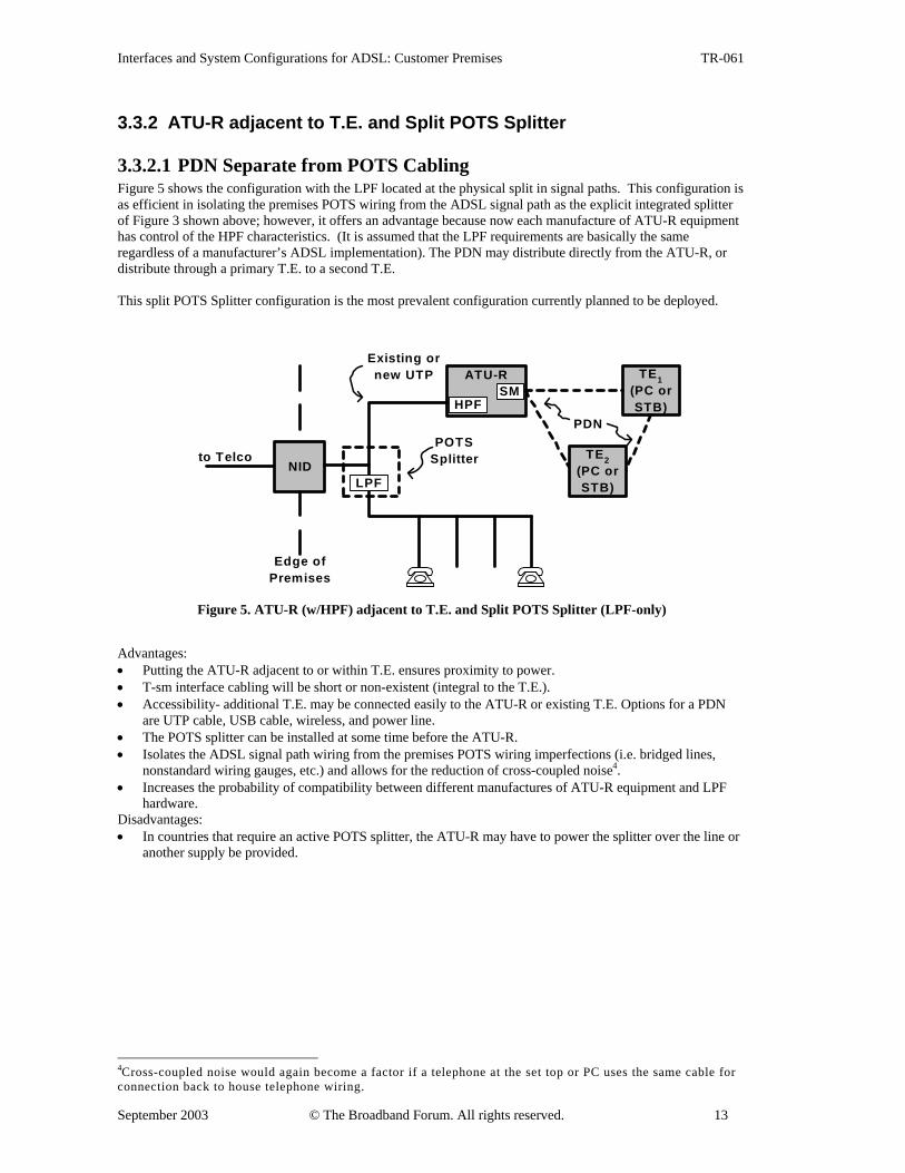
3.3.2.1 PDN Separate from POTS Cabling Figure 5 shows the configuration with the LPF located at the physical split in signal paths. This configuration is as efficient in isolating the premises POTS wiring from the ADSL signal path as the explicit integrated splitter of Figure 3 shown above; however, it offers an advantage because now each manufacture of ATU-R equipment has control of the HPF characteristics. (It is assumed that the LPF requirements are basically the same regardless of a manufacturer’s ADSL implementation). The PDN may distribute directly from the ATU-R, or distribute through a primary T.E. to a second T.E. This split POTS Splitter configuration is the most prevalent configuration currently planned to be deployed.
to Telco
Edge ofPremises
ATU-R
NIDLPF
HPF
Existing ornew UTP TE1
(PC orSTB)
PDN
TE2(PC orSTB)
SM
POTSSplitter
Figure 5. ATU-R (w/HPF) adjacent to T.E. and Split POTS Splitter (LPF-only)
Advantages: • Putting the ATU-R adjacent to or within T.E. ensures proximity to power. • T-sm interface cabling will be short or non-existent (integral to the T.E.). • Accessibility- additional T.E. may be connected easily to the ATU-R or existing T.E. Options for a PDN
are UTP cable, USB cable, wireless, and power line. • The POTS splitter can be installed at some time before the ATU-R. • Isolates the ADSL signal path wiring from the premises POTS wiring imperfections (i.e. bridged lines,
nonstandard wiring gauges, etc.) and allows for the reduction of cross-coupled noise4. • Increases the probability of compatibility between different manufactures of ATU-R equipment and LPF
hardware. Disadvantages: • In countries that require an active POTS splitter, the ATU-R may have to power the splitter over the line or
another supply be provided.
4Cross-coupled noise would again become a factor if a telephone at the set top or PC uses the same cable for connection back to house telephone wiring.
Interfaces and System Configurations for ADSL: Customer Premises TR-061
September 2003 © The Broadband Forum. All rights reserved. 14
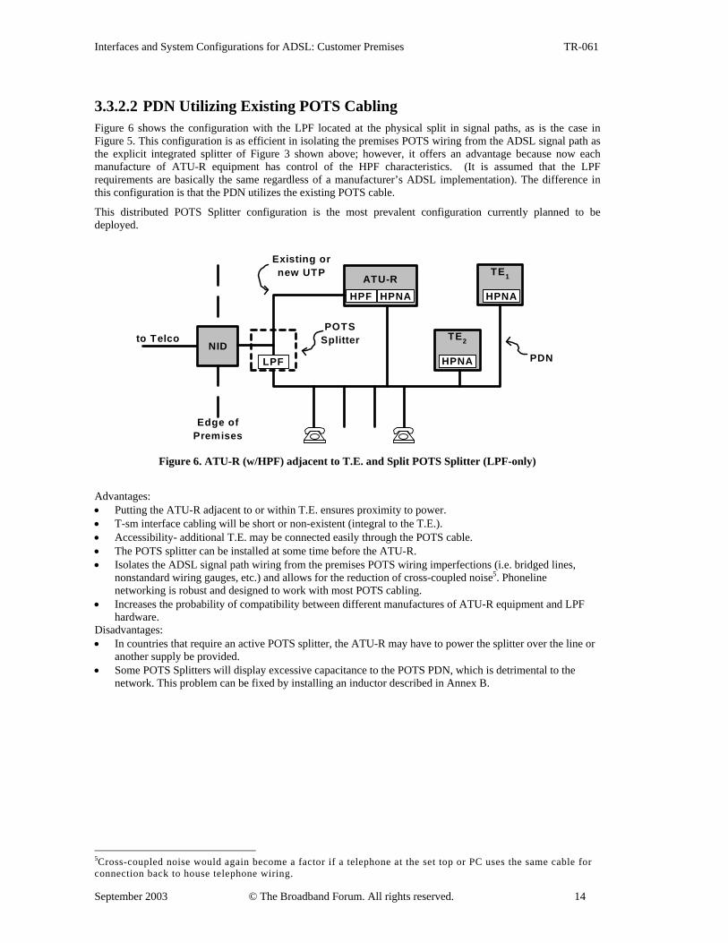
3.3.2.2 PDN Utilizing Existing POTS Cabling Figure 6 shows the configuration with the LPF located at the physical split in signal paths, as is the case in Figure 5. This configuration is as efficient in isolating the premises POTS wiring from the ADSL signal path as the explicit integrated splitter of Figure 3 shown above; however, it offers an advantage because now each manufacture of ATU-R equipment has control of the HPF characteristics. (It is assumed that the LPF requirements are basically the same regardless of a manufacturer’s ADSL implementation). The difference in this configuration is that the PDN utilizes the existing POTS cable.
This distributed POTS Splitter configuration is the most prevalent configuration currently planned to be deployed.
to Telco
Edge ofPremises
ATU-R
NIDLPF
HPF
Existing ornew UTP TE1
TE2
HPNA
HPNA
HPNA
PDN
POTSSplitter
Figure 6. ATU-R (w/HPF) adjacent to T.E. and Split POTS Splitter (LPF-only)
Advantages: • Putting the ATU-R adjacent to or within T.E. ensures proximity to power. • T-sm interface cabling will be short or non-existent (integral to the T.E.). • Accessibility- additional T.E. may be connected easily through the POTS cable. • The POTS splitter can be installed at some time before the ATU-R. • Isolates the ADSL signal path wiring from the premises POTS wiring imperfections (i.e. bridged lines,
nonstandard wiring gauges, etc.) and allows for the reduction of cross-coupled noise5. Phoneline networking is robust and designed to work with most POTS cabling.
• Increases the probability of compatibility between different manufactures of ATU-R equipment and LPF hardware.
Disadvantages: • In countries that require an active POTS splitter, the ATU-R may have to power the splitter over the line or
another supply be provided. • Some POTS Splitters will display excessive capacitance to the POTS PDN, which is detrimental to the
network. This problem can be fixed by installing an inductor described in Annex B.
5Cross-coupled noise would again become a factor if a telephone at the set top or PC uses the same cable for connection back to house telephone wiring.
Interfaces and System Configurations for ADSL: Customer Premises TR-061
September 2003 © The Broadband Forum. All rights reserved. 15
3.3.3 ATU-R adjacent to T.E. and Distributed POTS Splitter
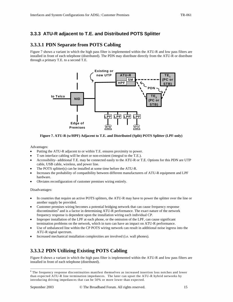
3.3.3.1 PDN Separate from POTS Cabling Figure 7 shows a variant in which the high pass filter is implemented within the ATU-R and low pass filters are installed in front of each telephone (distributed). The PDN may distribute directly from the ATU-R or distribute through a primary T.E. to a second T.E.
to Telco
Edge ofPremises
ATU-R
NID
TE1(PC orSTB)
PDN
TE2(PC orSTB)
HPF
Existing ornew UTP
LPFLPFLPFLPF
SM
Figure 7. ATU-R (w/HPF) Adjacent to T.E. and Distributed (Split) POTS Splitter (LPF-only)
Advantages: • Putting the ATU-R adjacent to or within T.E. ensures proximity to power. • T-sm interface cabling will be short or non-existent (integral to the T.E.). • Accessibility- additional T.E. may be connected easily to the ATU-R or T.E. Options for this PDN are UTP
cable, USB cable, wireless, and power line. • The POTS splitter(s) can be installed at some time before the ATU-R. • Increases the probability of compatibility between different manufacturers of ATU-R equipment and LPF
hardware. • Obviates reconfiguration of customer premises wiring entirely. Disadvantages: • In countries that require an active POTS splitters, the ATU-R may have to power the splitter over the line or
another supply be provided. • Customer premises wiring becomes a potential bridging network that can cause frequency response
discontinuities6 and is a factor in determining ATU-R performance. The exact nature of the network frequency response is dependent upon the installation wiring each individual CP.
• Improper installation of the LPF at each phone, or the omission of the LPF, can cause significant termination problems on the network, which in turn can have an impact on ATU-R performance.
• Use of unbalanced line within the CP POTS wiring network can result in additional noise ingress into the ATU-R signal spectrum.
• Increased mechanical installation complexities are involved (i.e. wall phones).
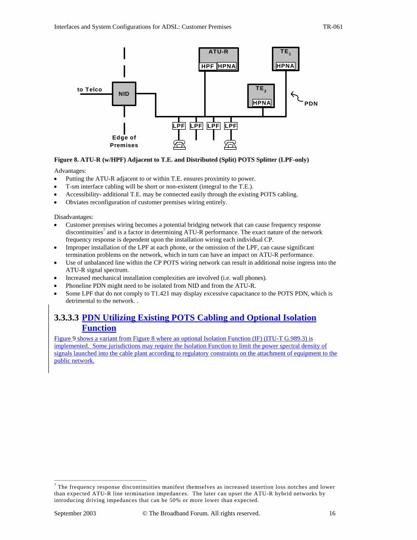
3.3.3.2 PDN Utilizing Existing POTS Cabling Figure 8 shows a variant in which the high pass filter is implemented within the ATU-R and low pass filters are installed in front of each telephone (distributed).
6 The frequency response discontinuities manifest themselves as increased insertion loss notches and lower than expected ATU-R line termination impedances. The later can upset the ATU-R hybrid networks by introducing driving impedances that can be 50% or more lower than expected.
Interfaces and System Configurations for ADSL: Customer Premises TR-061
September 2003 © The Broadband Forum. All rights reserved. 16
to Telco
Edge ofPremises
ATU-R
NID
HPF
LPFLPFLPFLPF
TE1
TE2
HPNA
HPNAHPNA
PDN
Figure 8. ATU-R (w/HPF) Adjacent to T.E. and Distributed (Split) POTS Splitter (LPF-only) Advantages: • Putting the ATU-R adjacent to or within T.E. ensures proximity to power. • T-sm interface cabling will be short or non-existent (integral to the T.E.). • Accessibility- additional T.E. may be connected easily through the existing POTS cabling. • Obviates reconfiguration of customer premises wiring entirely. Disadvantages: • Customer premises wiring becomes a potential bridging network that can cause frequency response
discontinuities7 and is a factor in determining ATU-R performance. The exact nature of the network frequency response is dependent upon the installation wiring each individual CP.
• Improper installation of the LPF at each phone, or the omission of the LPF, can cause significant termination problems on the network, which in turn can have an impact on ATU-R performance.
• Use of unbalanced line within the CP POTS wiring network can result in additional noise ingress into the ATU-R signal spectrum.
• Increased mechanical installation complexities are involved (i.e. wall phones). • Phoneline PDN might need to be isolated from NID and from the ATU-R. • Some LPF that do not comply to T1.421 may display excessive capacitance to the POTS PDN, which is
detrimental to the network. .
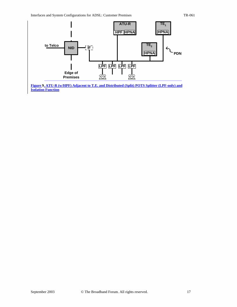
3.3.3.3 PDN Utilizing Existing POTS Cabling and Optional Isolation Function
Figure 9 shows a variant from Figure 8 where an optional Isolation Function (IF) (ITU-T G.989.3) is implemented. Some jurisdictions may require the Isolation Function to limit the power spectral density of signals launched into the cable plant according to regulatory constraints on the attachment of equipment to the public network.
7 The frequency response discontinuities manifest themselves as increased insertion loss notches and lower than expected ATU-R line termination impedances. The later can upset the ATU-R hybrid networks by introducing driving impedances that can be 50% or more lower than expected.
Interfaces and System Configurations for ADSL: Customer Premises TR-061
September 2003 © The Broadband Forum. All rights reserved. 17
to Telco
Edge ofPremises
ATU-R
NID
HPF
LPFLPFLPFLPF
TE1
TE2
HPNA
HPNAHPNA
PDNIF
Figure 9. ATU-R (w/HPF) Adjacent to T.E. and Distributed (Split) POTS Splitter (LPF-only) and Isolation Function
Interfaces and System Configurations for ADSL: Customer Premises TR-061
September 2003 © The Broadband Forum. All rights reserved. 18
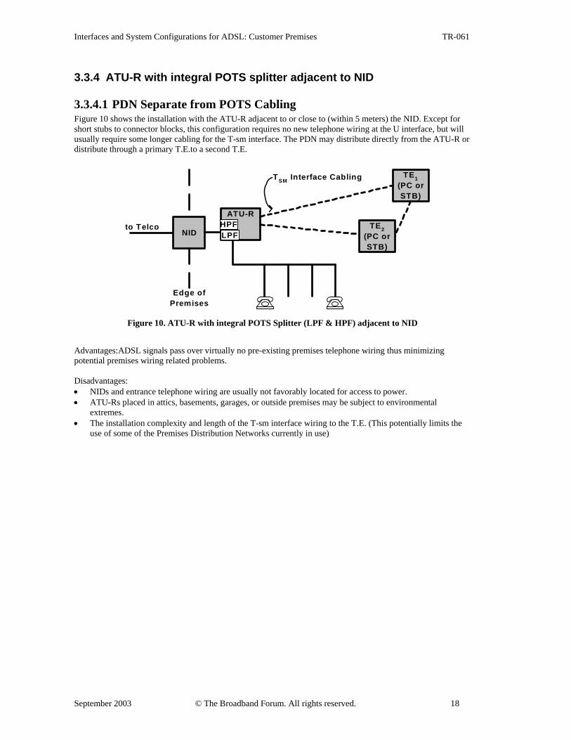
3.3.4 ATU-R with integral POTS splitter adjacent to NID
3.3.4.1 PDN Separate from POTS Cabling Figure 10 shows the installation with the ATU-R adjacent to or close to (within 5 meters) the NID. Except for short stubs to connector blocks, this configuration requires no new telephone wiring at the U interface, but will usually require some longer cabling for the T-sm interface. The PDN may distribute directly from the ATU-R or distribute through a primary T.E.to a second T.E.
to Telco
Edge ofPremises
ATU-R
NID
TE1(PC orSTB)
TE2(PC orSTB)
TSM Interface Cabling
HPFLPF
Figure 10. ATU-R with integral POTS Splitter (LPF & HPF) adjacent to NID
Advantages:ADSL signals pass over virtually no pre-existing premises telephone wiring thus minimizing potential premises wiring related problems. Disadvantages: • NIDs and entrance telephone wiring are usually not favorably located for access to power. • ATU-Rs placed in attics, basements, garages, or outside premises may be subject to environmental
extremes. • The installation complexity and length of the T-sm interface wiring to the T.E. (This potentially limits the
use of some of the Premises Distribution Networks currently in use)
Interfaces and System Configurations for ADSL: Customer Premises TR-061
September 2003 © The Broadband Forum. All rights reserved. 19
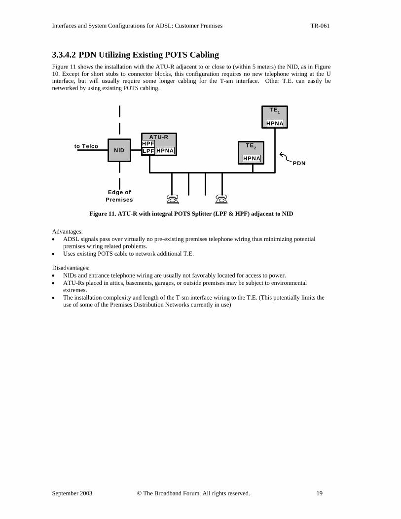
3.3.4.2 PDN Utilizing Existing POTS Cabling Figure 11 shows the installation with the ATU-R adjacent to or close to (within 5 meters) the NID, as in Figure 10. Except for short stubs to connector blocks, this configuration requires no new telephone wiring at the U interface, but will usually require some longer cabling for the T-sm interface. Other T.E. can easily be networked by using existing POTS cabling.
to Telco
Edge ofPremises
ATU-R
NID
TE1
TE2HPFLPF
PDN
HPNAHPNA
HPNA
Figure 11. ATU-R with integral POTS Splitter (LPF & HPF) adjacent to NID
Advantages: • ADSL signals pass over virtually no pre-existing premises telephone wiring thus minimizing potential
premises wiring related problems. • Uses existing POTS cable to network additional T.E. Disadvantages: • NIDs and entrance telephone wiring are usually not favorably located for access to power. • ATU-Rs placed in attics, basements, garages, or outside premises may be subject to environmental
extremes. • The installation complexity and length of the T-sm interface wiring to the T.E. (This potentially limits the
use of some of the Premises Distribution Networks currently in use)
Interfaces and System Configurations for ADSL: Customer Premises TR-061
September 2003 © The Broadband Forum. All rights reserved. 20
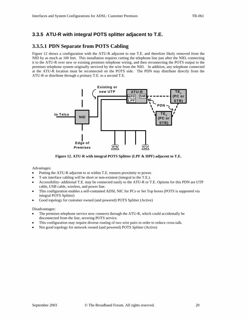
3.3.5 ATU-R with integral POTS splitter adjacent to T.E.
3.3.5.1 PDN Separate from POTS Cabling Figure 12 shows a configuration with the ATU-R adjacent to one T.E. and therefore likely removed from the NID by as much as 100 feet. This installation requires cutting the telephone line just after the NID, connecting it to the ATU-R over new or existing premises telephone wiring, and then reconnecting the POTS output to the premises telephone system originally serviced by the wire from the NID. In addition, any telephone connected at the ATU-R location must be reconnected on the POTS side. The PDN may distribute directly from the ATU-R or distribute through a primary T.E. to a second T.E.
to Telco
Edge ofPremises
ATU-R
NID
Existing ornew UTP TE1
(PC orSTB)
PDN
TE2(PC orSTB)
HPFLPF
SM
Figure 12. ATU-R with integral POTS Splitter (LPF & HPF) adjacent to T.E.
Advantages: • Putting the ATU-R adjacent to or within T.E. ensures proximity to power. • T-sm interface cabling will be short or non-existent (integral to the T.E.). • Accessibility- additional T.E. may be connected easily to the ATU-R or T.E. Options for this PDN are UTP
cable, USB cable, wireless, and power line. • This configuration enables a self-contained ADSL NIC for PCs or Set Top boxes (POTS is supported via
integral POTS Splitter) • Good topology for customer owned (and powered) POTS Splitter (Active) Disadvantages: • The premises telephone service now connects through the ATU-R, which could accidentally be
disconnected from the line, severing POTS service. • This configuration may require diverse routing of two wire pairs in order to reduce cross-talk. • Not good topology for network owned (and powered) POTS Splitter (Active)
Interfaces and System Configurations for ADSL: Customer Premises TR-061
September 2003 © The Broadband Forum. All rights reserved. 21
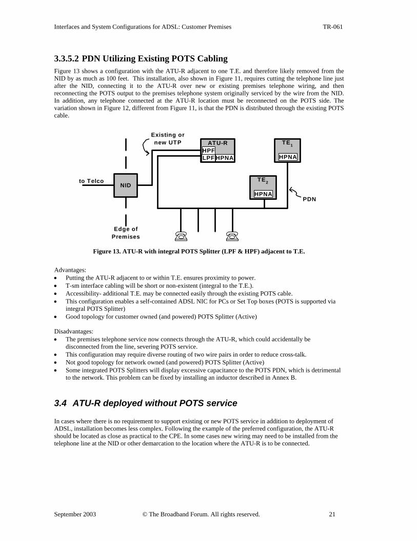
3.3.5.2 PDN Utilizing Existing POTS Cabling Figure 13 shows a configuration with the ATU-R adjacent to one T.E. and therefore likely removed from the NID by as much as 100 feet. This installation, also shown in Figure 11, requires cutting the telephone line just after the NID, connecting it to the ATU-R over new or existing premises telephone wiring, and then reconnecting the POTS output to the premises telephone system originally serviced by the wire from the NID. In addition, any telephone connected at the ATU-R location must be reconnected on the POTS side. The variation shown in Figure 12, different from Figure 11, is that the PDN is distributed through the existing POTS cable.
to Telco
Edge ofPremises
NID
TE1
TE2
ATU-RExisting ornew UTP
HPFLPF HPNAHPNA
PDNHPNA
Figure 13. ATU-R with integral POTS Splitter (LPF & HPF) adjacent to T.E.
Advantages: • Putting the ATU-R adjacent to or within T.E. ensures proximity to power. • T-sm interface cabling will be short or non-existent (integral to the T.E.). • Accessibility- additional T.E. may be connected easily through the existing POTS cable. • This configuration enables a self-contained ADSL NIC for PCs or Set Top boxes (POTS is supported via
integral POTS Splitter) • Good topology for customer owned (and powered) POTS Splitter (Active) Disadvantages: • The premises telephone service now connects through the ATU-R, which could accidentally be
disconnected from the line, severing POTS service. • This configuration may require diverse routing of two wire pairs in order to reduce cross-talk. • Not good topology for network owned (and powered) POTS Splitter (Active) • Some integrated POTS Splitters will display excessive capacitance to the POTS PDN, which is detrimental
to the network. This problem can be fixed by installing an inductor described in Annex B.
3.4 ATU-R deployed without POTS service In cases where there is no requirement to support existing or new POTS service in addition to deployment of ADSL, installation becomes less complex. Following the example of the preferred configuration, the ATU-R should be located as close as practical to the CPE. In some cases new wiring may need to be installed from the telephone line at the NID or other demarcation to the location where the ATU-R is to be connected.
Interfaces and System Configurations for ADSL: Customer Premises TR-061
September 2003 © The Broadband Forum. All rights reserved. 22
4 U-R, POTS-R, U-R2 Interfaces
4.1 Wiring Considerations The majority of ADSL installations use the existing phoneline, utilizing a self-install kit and in-line filters as distributed splitters. This common type of installation is shown in Figure 8. It is a favorable type of installation, due to eliminating the technician visit and costs involved. Other types of installations require the need for additional wiring and signal routing, as shown in the remaining figures of section 3. If new wiring is installed, it should be UTP Category 5 as specified in EIA/TIA 570. A wall plate shall be installed to terminate the new wiring for DSL. • Utilizing unused pairs of wire in existing phoneline to route an ADSL signal that has already been split from the POTS is not recommended and could result in poor or no service. The running of ADSL signals and POTS signals together through a single two-pair cable (ADSL on one pair and POTS on the other), cross-couples POTS noises generated by ringing, trip ringing, pulse dialing, and hook switch signaling into the low level ADSL receive signals. Studies have shown that just a few feet of adjacent wiring causes cross-coupling of sufficient magnitude to cause errors in received data. This problem could be reduced by the high pass filtering in the ATU-R. This liability is also mitigated by error control protocols and by interleaving (the noise appears as impulses), but must be recognized as having potential effects on quality of service. However, there is also concern that there may be detrimental effects (unacceptable noise in the telephone user’s ear) from cross-coupling of ADSL signals into the post splitter POTS lines. This potential for crosstalk may affect voice band usage that extends near 4000 Hz such as with V.pcm or other high speed voice band modems.
4.2 U-R or U-R2 The U-R is the interface between the loop and the splitter. Typical implementations are screw terminals or RJ11 jack/plug in the NID box as required by specific configuration, wired to center pair (pins 3 and 4). In the case of distributed splitters, the U-R connection is between the loop and the ATU, and the ATU should have the high pass filtering installed.
The U-R2 is the interface between the splitter and the ATU. With a splitter installed in the NID, there may be screw terminals or an RJ11 or RJ45 jack to connect a dedicated CAT-5 UTP ADSL data cable (pins 2 and 5) which will be run to a convenient wall outlet (RJ14 or RJ11) or directly to the ATU-R. The ATU-R incorporates a U-R or U–R2 interface for the ADSL connection. The ATU-R has an option for integrating the POTS splitter using one of the following methods: • Split POTS Splitter as described in Section 3.3.2 (HPF internal to ATU-R).
The U-R2 connector at the wall jack shall be RJ14 (sometimes known as RJ11, 4-wire) with ADSL wired to pins 2 and 5. POTS (optional) will be wired to pins 3 and 4. This wiring precludes the use of a POTS second line on a wire pair connected to pins 2 and 5 for this particular wall jack. In cases where wiring other than UTP Category 5 is being used, the ADSL signal path from the POTS Splitter to the U-R2 connector at the wall jack must be isolated in a separate sheath. This may require a new cable run.
• Internal POTS Splitter as described in Sections 3.3.4 and 3.3.5. The U-R2 connector at the wall jack shall be as specified in the physical characteristics section of ANSI T1.413.
4.3 POTS-R The interface between the loop and the phone is labeled POTS-R. Typical implementations are screw terminals or RJ11 jack/plug in the NID as required by specific configuration wired to center pair (pins 3 and 4), connecting existing phoneline to wall jacks to which the phone’s cable are connected. In-line filters may be inserted between the wall jack and the phone cable, as close to the wall jack as possible. With a splitter installed in the NID, an in-line filter is not required and the screw terminals or RJ11 jack/plug will connect existing phoneline to a wall jack, to which the phone’s cable is connected.
Interfaces and System Configurations for ADSL: Customer Premises TR-061
September 2003 © The Broadband Forum. All rights reserved. 23
5 T-SM Interface If the ATU-R is merely implementing the basic functions of a bit pump, an external T-sm interface will be necessary to interconnect the ATU-R to a separate Service Module. This interface will have to carry those data, timing and control signals necessary to permit operation of a variety of services which may be carried on the ADSL link. The minimum signal set will be one downstream data circuit plus its clock and one upstream data circuit plus its clock. A number of optional signals may be supported for particular applications: 1. Secondary data channels. These may be simplex or duplex channels and will always have an associated
clock. Some duplex channels may have a common clock. 2. Auxiliary data timing signals. Some channels may require an out-of-band frame or byte start signal which is
extracted from the ADSL framing structure. 3. Network Timing Reference. Some service modules may require the 8kHz timing reference when this is
carried by the ADSL link. 4. Control and Status circuits. The ATU-R and SM may each be required to control the other and/or to receive
status indications. These may be global signals or be channel associated. A basic interface providing the minimum signal set on an RJ45 connector is specified here where this is sufficient. It is recommended that interfaces which provide additional signals use one of the existing ISO data communications interfaces. The data rate of ADSL equipment requires that only those interfaces using balanced circuits should be used. Suitable interfaces are: ISO.4903 (X.21), ISO.2110-Amd1 (TIA.530) or ISO.2593 (V.35). The use of such interfaces will allow existing data communications equipment to connect to an ATU-R without modification. Guidance is given below as to the mapping of the T-sm signals onto these interfaces.
5.1 Signal Specifications Each simplex data channel consists of one data circuit (DD or DU) and one clock circuit (CD or CU). The clocks are normally generated by the ATU-R, but in some instances the upstream clock (CU) may be generated by the SM. These clocks should have a nominal 50% duty cycle at the maximum data rate. Extended OFF periods may be inserted when burst clocking is being used. The downstream data is generated by the ATU-R and the upstream data by the SM. The data is NRZ encoded with the OFF and ON states representing logic 1 and 0 respectively. Data changes state at OFF to ON clock transitions, with the receiver strobing the data at ON to OFF clock transitions. In addition to the clock and data signals, each channel or group of channels may have other signals associated with them. ATU-R and SM equipment not generating these signals shall leave these circuits unconnected, and equipment receiving these signals shall provide pullups/pulldowns so as to force an ON state in the event an undriven input. The channel-associated signals may include: 1. Data Qualifier (QD or QU). A signal driven by the data source to indicate valid data on its transmitter. This
signal may be used in place of, or in addition to, burst clocking. 2. Channel Control (CC). A signal generated by the SM to enable channel(s). 3. Channel Indication (CI). A signal generated by the ATU-R to indicate that channel(s) are in a data-
forwarding state. 4. Byte Sync (BS). A signal generated by the ATU-R to provide a data alignment signal for byte-structured
channels such as G.711 PCM. This signal shall transition from OFF to ON on the byte boundary and may transition from ON to OFF at any other bit boundary.
5. Frame Sync (FS). A signal generated by the ATU-R to provide data alignment for frame-structured channels which do not have an embedded frame delimiter. This signal shall transition from OFF to ON at the frame boundary and may transition from ON to OFF at any other bit boundary.
6. Network Timing Reference (NR). This is a signal with a frequency of 8 kHz which may be carried by some ADSL links.
Global control and indication signals may be used which relate to the entire ADSL link: 1. Equipment Status (SD or SU): A signal generated by either equipment to indicate that it is operational and
to qualify all other signals. 2. Link Control (LC): A signal generated by the SM to enable the ADSL link. 3. Link Indication (LI): A signal generated by the ATU-R to indicate that the ADSL link is operational.
Interfaces and System Configurations for ADSL: Customer Premises TR-061
September 2003 © The Broadband Forum. All rights reserved. 24
Notes: 1. In both the above lists, item 1 is an alternative to 2 plus 3. This equates to the alternative definitions of
circuit 108 in ITU-T V.24 as either Data Terminal Ready or Connect Data Set to Line. 2. Where only one pair of channels is supported, Channel Control/Indication and Link Control/Indication are
essentially the same signals. 3. No signals relating to flow control or SM-sourced clocks are specified. It cannot be assumed that an ATU-R
is capable of either flow control or speed buffering and therefore all data flow must be slaved to the ATU-R clocks. Where SM equipment needs such facilities, they should be provided internally by the SM.
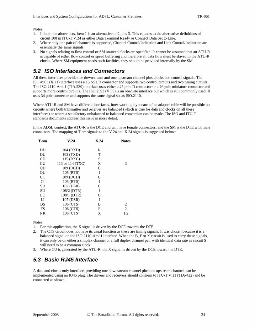
5.2 ISO Interfaces and Connectors All these interfaces provide one downstream and one upstream channel plus clocks and control signals. The ISO.4903 (X.21) interface uses a 15 pole D connector and supports two control circuits and two timing circuits. The ISO.2110-Amd1 (TIA.530) interface uses either a 25 pole D connector or a 26 pole miniature connector and supports more control circuits. The ISO.2593 (V.35) is an obsolete interface but which is still commonly used. It uses 34 pole connector and supports the same signal set as ISO.2110. Where ATU-R and SM have different interfaces, inter-working by means of an adapter cable will be possible on circuits where both transmitter and receiver are balanced (which is true for data and clocks on all these interfaces) or where a satisfactory unbalanced to balanced conversion can be made. The ISO and ITU-T standards documents address this issue in more detail. In the ADSL context, the ATU-R is the DCE and will have female connectors, and the SM is the DTE with male connectors. The mapping of T-sm signals to the V.24 and X.24 signals is suggested below:
T-sm V.24 X.24 Notes
DD 104 (RXD) R DU 103 (TXD) T CD 115 (RXC) S CU 113 or 114 (TXC) X 3 QD 109 (DCD) C QU 105 (RTS) I CC 109 (DCD) C CI 105 (RTS) I SD 107 (DSR) C SU 108/2 (DTR) I LC 108/1 (DTR) C LI 107 (DSR) I BS 106 (CTS) B 2 FS 106 (CTS) F 2 NR 106 (CTS) X 1,2
Notes: 1. For this application, the X signal is driven by the DCE towards the DTE. 2. The CTS circuit does not have its usual function as these are timing signals. It was chosen because it is a
balanced signal on the ISO.2110-Amd1 interface. When the B, F or X circuit is used to carry these signals, it can only be on either a simplex channel or a full duplex channel pair with identical data rate as circuit S will need to be a common clock.
3. Where CU is generated by the ATU-R, the X signal is driven by the DCE toward the DTE.
5.3 Basic RJ45 Interface
A data and clocks only interface, providing one downstream channel plus one upstream channel, can be implemented using an RJ45 plug. The drivers and receivers should conform to ITU-T V.11 (TIA-422) and be connected as shown:

Interfaces and System Configurations for ADSL: Customer Premises TR-061
September 2003 © The Broadband Forum. All rights reserved. 25
CDaCDbDUaCUaCUbDUbDDaDDb
Pin #1Pin #2Pin #3Pin #4Pin #5Pin #6Pin #7Pin #8
Figure 14. RJ45 Plug for the T-SM Interface
It may be necessary to use screened RJ45 jacks, plugs and cables to meet radiated emissions requirements.
Interfaces and System Configurations for ADSL: Customer Premises TR-061
September 2003 © The Broadband Forum. All rights reserved. 26
6 T-PDN Interfaces - existing Premises Distribution Networks
With the addition of a Service Module, the T-SM interface may be converted to a more commonly available interface. When the ATU-R and SM functions are integrated into one device, the T-SM interface will disappear at the physical level and the applicable interface then becomes the T-PDN.
The Premises Distribution Networks described in this section are some of the commonly available PDNs in use for Bit Synchronous (serial interface data communications) Mode, Packet Mode and ATM Mode of operation.
6.1 Bit Synchronous Interfaces Terminal Equipment such as routers or Set Top boxes may support some of the more common serial interface data communications connections (DTE interfaces) at the T-PDN interface. The Terminal Equipment expects the device attached at the T-PDN interface to act as a Data Communications Equipment (DCE).
The following specifications are incorporated in this document by reference and will not be further detailed herein: • TIA-530 or v.35 (ISO 2593) for high speed serial DTE interface. • T1 - 1.544 Mbps ANSI T1.403 • E1 - 2.048 Mbps ITU G.703/G.704
6.2 Ethernet 10BaseT interface The following specifications are incorporated in this document by reference and will not be further detailed herein: • 10BaseT on a RJ-45 connector
• Ethernet Version 2.0: A CSMA/CD Local Area Network Specification • ANSI/IEEE 802.3, CSMA/CD Access Method and Physical Layer Specifications
6.3 HomePNA (ITU G.989) The use of existing home phonelines for networking multiple computers or digital devices has been specified by HomePNA (Home Phoneline Networking Alliance); and their proposal has been adopted by the ITU in Recommendations G.989.1 and G.989.2. Annex B is provided for further information concerning this technology which shares the same cabling as POTS and splitterless ADSL.
6.4 CEBus A high speed digital home network serving the needs of ADSL signal distribution and digital information distribution from other local or network resources can be implemented on a high quality unshielded twisted pair wiring system. This type of infrastructure has been proposed by the CEBus (Consumer Electronics Bus) committee which recommends the installation of Category 5 unshielded twisted pair in a star topology for both voice and data transmission purposes.
Note: Category 5 unshielded twisted pair is also the transmission media for 100BaseTX Ethernet and several other systems. Such an infrastructure would be suitable for the ATM based system being proposed by the ATM Forum.
6.5 IEEE 1394 (Firewire) IEEE 1394 (1995) is an IEEE serial bus standard originally designed for the inter-connection of computer peripheral devices. The 1394 standard defines a serial interface that can be used to replace traditional PC parallel, serial, or SCSI bus. The 1394 standard is designed to handle both isochronous and asynchonous data
Interfaces and System Configurations for ADSL: Customer Premises TR-061
September 2003 © The Broadband Forum. All rights reserved. 27
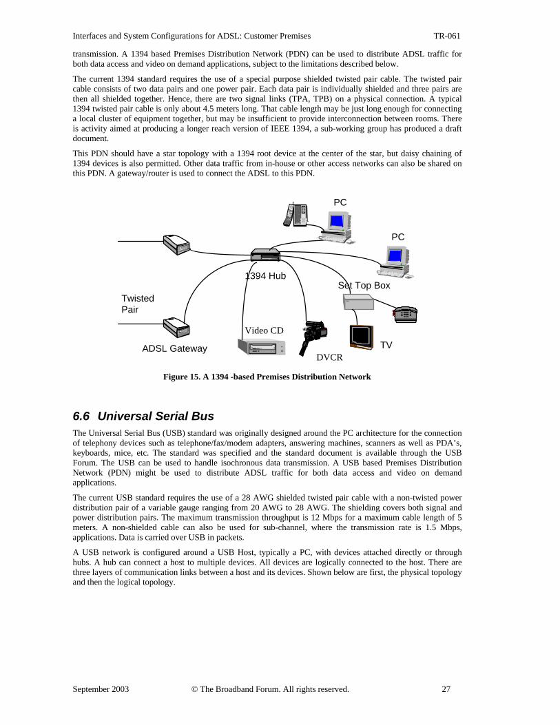
transmission. A 1394 based Premises Distribution Network (PDN) can be used to distribute ADSL traffic for both data access and video on demand applications, subject to the limitations described below.
The current 1394 standard requires the use of a special purpose shielded twisted pair cable. The twisted pair cable consists of two data pairs and one power pair. Each data pair is individually shielded and three pairs are then all shielded together. Hence, there are two signal links (TPA, TPB) on a physical connection. A typical 1394 twisted pair cable is only about 4.5 meters long. That cable length may be just long enough for connecting a local cluster of equipment together, but may be insufficient to provide interconnection between rooms. There is activity aimed at producing a longer reach version of IEEE 1394, a sub-working group has produced a draft document.
This PDN should have a star topology with a 1394 root device at the center of the star, but daisy chaining of 1394 devices is also permitted. Other data traffic from in-house or other access networks can also be shared on this PDN. A gateway/router is used to connect the ADSL to this PDN.
TwistedPair
1394 Hub
ADSL Gateway
PC
PC
Video CD
DVCRTV
Set Top Box
Figure 15. A 1394 -based Premises Distribution Network
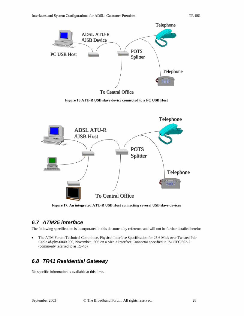
6.6 Universal Serial Bus The Universal Serial Bus (USB) standard was originally designed around the PC architecture for the connection of telephony devices such as telephone/fax/modem adapters, answering machines, scanners as well as PDA’s, keyboards, mice, etc. The standard was specified and the standard document is available through the USB Forum. The USB can be used to handle isochronous data transmission. A USB based Premises Distribution Network (PDN) might be used to distribute ADSL traffic for both data access and video on demand applications.
The current USB standard requires the use of a 28 AWG shielded twisted pair cable with a non-twisted power distribution pair of a variable gauge ranging from 20 AWG to 28 AWG. The shielding covers both signal and power distribution pairs. The maximum transmission throughput is 12 Mbps for a maximum cable length of 5 meters. A non-shielded cable can also be used for sub-channel, where the transmission rate is 1.5 Mbps, applications. Data is carried over USB in packets.
A USB network is configured around a USB Host, typically a PC, with devices attached directly or through hubs. A hub can connect a host to multiple devices. All devices are logically connected to the host. There are three layers of communication links between a host and its devices. Shown below are first, the physical topology and then the logical topology.
Interfaces and System Configurations for ADSL: Customer Premises TR-061
September 2003 © The Broadband Forum. All rights reserved. 28
POTSPOTSSplitterSplitter
ADSL ATU-RADSL ATU-R/USB Device/USB Device
To Central OfficeTo Central Office
TelephoneTelephone
TelephoneTelephone
PC USB HostPC USB Host
Figure 16 ATU-R USB slave device connected to a PC USB Host
POTSPOTSSplitterSplitter
ADSL ATU-RADSL ATU-R/USB Host/USB Host
To Central OfficeTo Central Office
TelephoneTelephone
TelephoneTelephone
Figure 17. An integrated ATU-R USB Host connecting several USB slave devices
6.7 ATM25 interface The following specification is incorporated in this document by reference and will not be further detailed herein: • The ATM Forum Technical Committee, Physical Interface Specification for 25.6 Mb/s over Twisted Pair
Cable af-phy-0040.000, November 1995 on a Media Interface Connector specified in ISO/IEC 603-7 (commonly referred to as RJ-45)
6.8 TR41 Residential Gateway No specific information is available at this time.
Interfaces and System Configurations for ADSL: Customer Premises TR-061
September 2003 © The Broadband Forum. All rights reserved. 29
7 Annex A The Broadband Forum System Reference Model
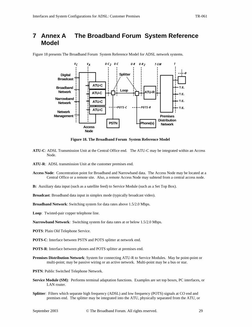
Figure 18 presents The Broadband Forum System Reference Model for ADSL network systems.
NetworkManagement
T
ATU-R
AccessNode
ATU-C
ATU-C
ATU-C
ATU-C
BroadbandNetwork
NarrowbandNetwork
DigitalBroadcast
PSTN
PremisesDistribution
Network
T-SMU-C
POTS-C POTS-R
Loop
Splitter
Phone(s)
U-C2 U-R2VAVC U-R
T.E.
T.E.
T.E.
T.E.
B
Figure 18. The Broadband Forum System Reference Model
ATU-C: ADSL Transmission Unit at the Central Office end. The ATU-C may be integrated within an Access
Node. ATU-R: ADSL transmission Unit at the customer premises end. Access Node: Concentration point for Broadband and Narrowband data. The Access Node may be located at a
Central Office or a remote site. Also, a remote Access Node may subtend from a central access node. B: Auxiliary data input (such as a satellite feed) to Service Module (such as a Set Top Box). Broadcast: Broadband data input in simplex mode (typically broadcast video). Broadband Network: Switching system for data rates above 1.5/2.0 Mbps. Loop: Twisted-pair copper telephone line. Narrowband Network: Switching system for data rates at or below 1.5/2.0 Mbps. POTS: Plain Old Telephone Service. POTS-C: Interface between PSTN and POTS splitter at network end. POTS-R: Interface between phones and POTS splitter at premises end. Premises Distribution Network: System for connecting ATU-R to Service Modules. May be point-point or
multi-point; may be passive wiring or an active network. Multi-point may be a bus or star. PSTN: Public Switched Telephone Network. Service Module (SM): Performs terminal adaptation functions. Examples are set top boxes, PC interfaces, or
LAN router. Splitter: Filters which separate high frequency (ADSL) and low frequency (POTS) signals at CO end and
premises end. The splitter may be integrated into the ATU, physically separated from the ATU, or
Interfaces and System Configurations for ADSL: Customer Premises TR-061
September 2003 © The Broadband Forum. All rights reserved. 30
divided between high pass and low pass, with the low pass function physically separated from the ATU. The provision of POTS splitters and POTS-related functions is optional.
T-SM: Interface between ATU-R and Premises Distribution Network. May be same as T when network is
point-point passive wiring. An ATU-R may have more than one type of T-SM interface implemented (e.g., a T1/E1 connection and an Ethernet connection).
T: Interface between Premises Distribution Network and Service Modules. May be same as T-SM when
network is point-point passive wiring. Note that T interface may disappear at the physical level when ATU-R is integrated within an Service Module.
U-C: Interface between Loop and ATU-C (analog). Defining both ends of the Loop interface separately arises
because of the asymmetry of the signals on the line. U-C2: Interface between POTS splitter and ATU-C. Note that at present ANSI T1.413 does not define such an interface and separating the POTS splitter from the ATU-C presents some technical difficulties in standardizing this interface. U-R: Interface between Loop and ATU-R (analog). U-R2: Interface between POTS splitter and ATU-R. Note that at present ANSI T1.413 does not define such an
interface and separating the POTS splitter from the ATU-R presents some technical difficulties in standardizing the interface.
VA: Logical interface between ATU-C and Access Node. As this interface will often be within circuits on a
common board, The Broadband Forum does not consider physical VA interfaces. The V interface may contain STM, ATM, or both transfer modes. In the primitive case of point-point connection between a switch port and an ATU-C (that is, a case without concentration or multiplexing), then the VA and VC interfaces become identical (alternatively, the VA interface disappears).
VC: Interface between Access Node and network. May have multiple physical connections (as shown) although
may also carry all signals across a single physical connection. A digital carrier facility (e.g., a SONET or SDH extension) may be interposed at the VC interface when the access node and ATU-Cs are located at a remote site. Interface to the PSTN may be a universal tip-ring interface or a multiplexed telephony interface such as specified in Bellcore TR-08 or TR-303. The broadband segment of the VC interface may be STM switching, ATM switching, or private line type connections.
Interfaces and System Configurations for ADSL: Customer Premises TR-061
September 2003 © The Broadband Forum. All rights reserved. 31
8 Annex B Premise Distribution Network Sharing POTS/ADSL Cabling
The information in this Annex addresses the issues that arise from utilizing an existing in-premise phoneline for PDN signals, POTS service and ADSL traffic. Figure 19 shows the frequency spectrum of the three signals, which enables them to simultaneously coexist on the in-premise.
In this Annex, two cases are considered: Splitter and Splitterless Configurations. The splitter is a frequency selective device used to aid in the isolation of POTS impairments from interfering with ADSL, as well as ADSL impairments interfering with POTS.
POTSISDN ADSL
ADSL+HomePNA
G.989
Figure 19. POTS/ADSL/HomePNA Spectrum
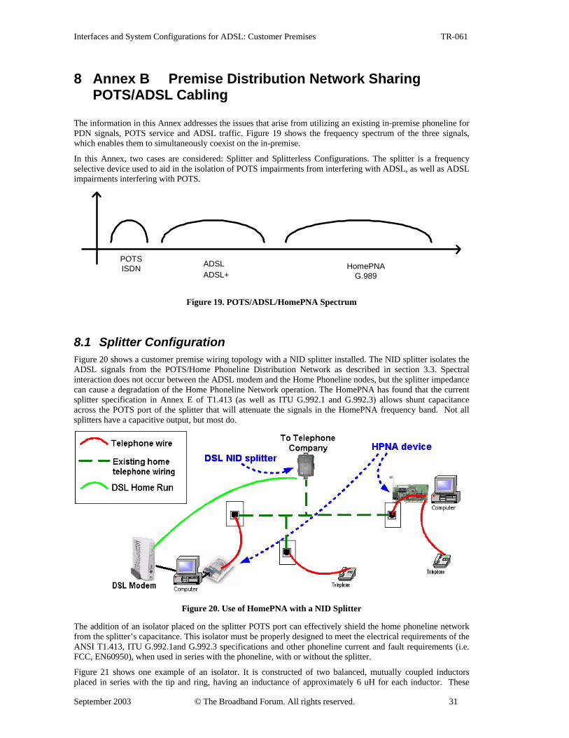
8.1 Splitter Configuration Figure 20 shows a customer premise wiring topology with a NID splitter installed. The NID splitter isolates the ADSL signals from the POTS/Home Phoneline Distribution Network as described in section 3.3. Spectral interaction does not occur between the ADSL modem and the Home Phoneline nodes, but the splitter impedance can cause a degradation of the Home Phoneline Network operation. The HomePNA has found that the current splitter specification in Annex E of T1.413 (as well as ITU G.992.1 and G.992.3) allows shunt capacitance across the POTS port of the splitter that will attenuate the signals in the HomePNA frequency band. Not all splitters have a capacitive output, but most do.
Figure 20. Use of HomePNA with a NID Splitter
The addition of an isolator placed on the splitter POTS port can effectively shield the home phoneline network from the splitter’s capacitance. This isolator must be properly designed to meet the electrical requirements of the ANSI T1.413, ITU G.992.1and G.992.3 specifications and other phoneline current and fault requirements (i.e. FCC, EN60950), when used in series with the phoneline, with or without the splitter.
Figure 21 shows one example of an isolator. It is constructed of two balanced, mutually coupled inductors placed in series with the tip and ring, having an inductance of approximately 6 uH for each inductor. These
Interfaces and System Configurations for ADSL: Customer Premises TR-061
September 2003 © The Broadband Forum. All rights reserved. 32
inductors must be designed to hold their inductance in the presence of phoneline DC currents, while having very low DC resistance. Applicable POTS electrical requirements are found in the annex of ANSI T1.413/ITU G.992.1/G.992.3 specifications. The inductors used in this example typically have less than one ohm of DC resistance, while presenting over 300 ohms of AC impedance to phoneline network signals in the spectrum of 4 to 10 MHz. The value of 300 ohms is an example of AC impedance large enough not to load down the network.
OriginalPOTS portterminatingcapacitor
Addedmutuallycoupledseries
inductors
HomePNAnetwork
Figure 21. Example Isolator
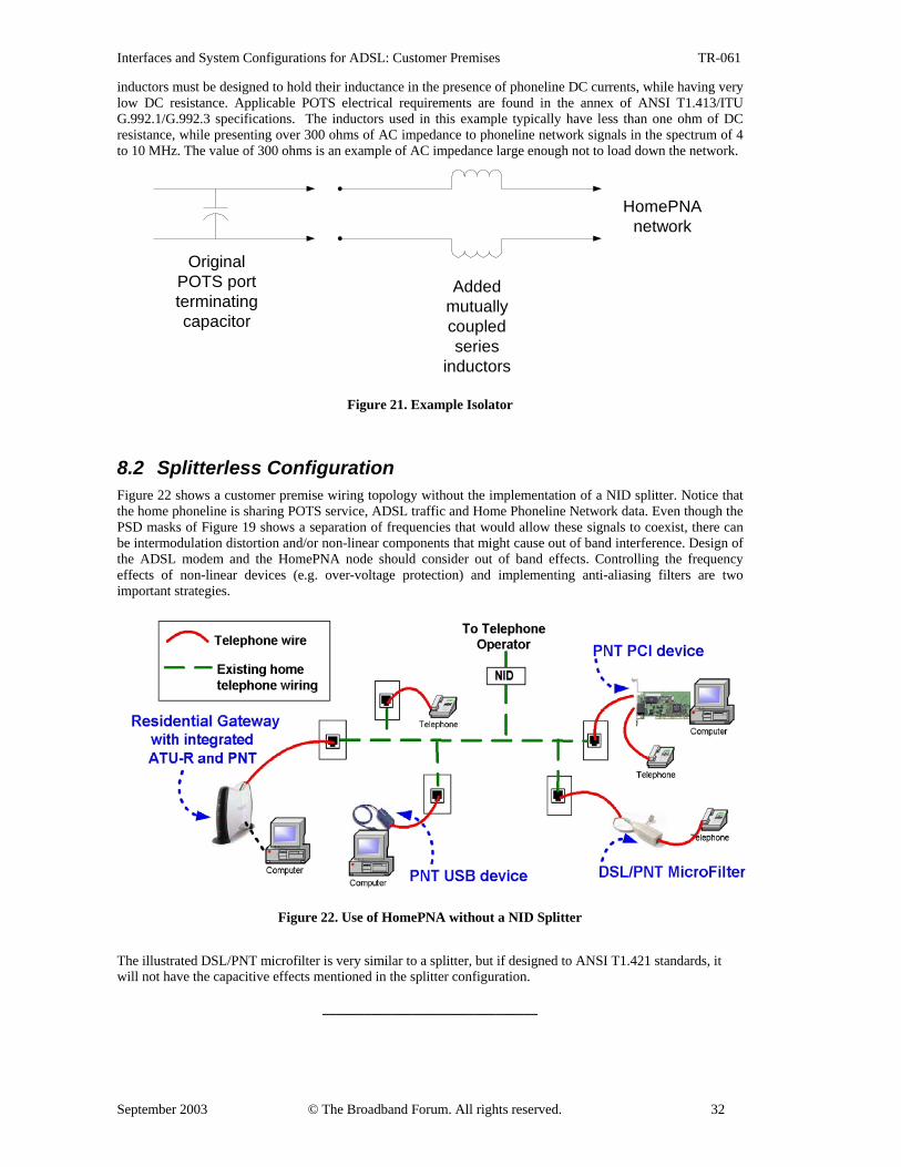
8.2 Splitterless Configuration Figure 22 shows a customer premise wiring topology without the implementation of a NID splitter. Notice that the home phoneline is sharing POTS service, ADSL traffic and Home Phoneline Network data. Even though the PSD masks of Figure 19 shows a separation of frequencies that would allow these signals to coexist, there can be intermodulation distortion and/or non-linear components that might cause out of band interference. Design of the ADSL modem and the HomePNA node should consider out of band effects. Controlling the frequency effects of non-linear devices (e.g. over-voltage protection) and implementing anti-aliasing filters are two important strategies.
Figure 22. Use of HomePNA without a NID Splitter
The illustrated DSL/PNT microfilter is very similar to a splitter, but if designed to ANSI T1.421 standards, it will not have the capacitive effects mentioned in the splitter configuration.
_______________________________