Embed Size (px)
Citation preview

VIN
BOOT
SW
ILIM
FB
COMP
PGD
EN/SS
TPS56121
BPVDDGND
VIN
VOUT
VIN
SD
VOUT
UDG-11047
Product
Folder
Sample &Buy
Technical
Documents
Tools &
Software
Support &Community
An IMPORTANT NOTICE at the end of this data sheet addresses availability, warranty, changes, use in safety-critical applications,intellectual property matters and other important disclaimers. PRODUCTION DATA.
TPS56121SLUSAH4D –MARCH 2011–REVISED FEBRUARY 2016
TPS56121 4.5-V to 14-V Input High-Current Synchronous Buck SWIFT™ Converter
1
1 Features1• 4.5-V to 14-V Input Voltage Range• Incorporates Power Block Technology• Up to 15-A Output Current• Fixed-Frequency Options of 300 kHz, 500 kHz,
and 1 MHz• High-Side and Low-Side MOSFET RDS(on) Sensing• Programmable Soft-Start• 600-mV Reference Voltage With 1% Accuracy• Voltage Mode Control with Feed-Forward• Supports Prebiased Output• Thermal Shutdown• 22-Pin 5-mm x 6-mm PQFN PowerPAD™
Package• For SWIFT™ Power Products Documentation,
see http://www.ti.com/swift
2 Applications• Point-of-Load (POL) Power Modules• High-Density DC-DC Converters for Telecom and
Networking Applications
3 DescriptionThe TPS56121 device is a high-efficiency and high-current synchronous buck converter designed tooperate from a supply of 4.5 V to 14 V. The devicecan produce an output voltage as low as 0.6 V atloads up to 15 A. Integrated NexFET™ PowerMOSFETs provide a small footprint and ease of use.
The device implements a voltage-mode control withvoltage feed-forward compensation that respondsinstantly to input voltage change.
The TPS56121 is available in a thermally enhanced22-pin PQFN (DQP) PowerPAD package.
The device offers design flexibility with a variety ofuser programmable functions, including soft-start,overcurrent protection (OCP) levels, and loopcompensation. OCP levels are programmed by asingle external resistor connected from the ILIM pin tothe circuit ground. During the initial power-onsequence, the device enters a calibration cycle,measures the voltage at the ILIM pin, and sets aninternal OCP voltage level. During operation, theprogrammed OCP voltage level is compared to thevoltage drop across the low-side FET when it is on todetermine whether there is an overcurrent conditionand then enters a shutdown/restart cycle until thefault is removed.
Device Information(1)
PART NUMBER PACKAGE BODY SIZE (NOM)TPS56121 LSON-CLIP (22) 6.00 mm × 5.00 mm
(1) For all available packages, see the orderable addendum atthe end of the datasheet.
Simplified Application

2
TPS56121SLUSAH4D –MARCH 2011–REVISED FEBRUARY 2016 www.ti.com
Product Folder Links: TPS56121
Submit Documentation Feedback Copyright © 2011–2016, Texas Instruments Incorporated
Table of Contents1 Features .................................................................. 12 Applications ........................................................... 13 Description ............................................................. 14 Revision History..................................................... 25 Pin Configuration and Functions ......................... 36 Specifications......................................................... 4
6.1 Absolute Maximum Ratings ...................................... 46.2 ESD Ratings.............................................................. 46.3 Recommended Operating Conditions....................... 46.4 Thermal Information .................................................. 56.5 Electrical Characteristics........................................... 56.6 Typical Characteristics .............................................. 7
7 Detailed Description ............................................ 107.1 Overview ................................................................. 107.2 Functional Block Diagram ....................................... 10
7.3 Feature Description................................................. 107.4 Device Functional Modes........................................ 14
8 Application and Implementation ........................ 158.1 Application Information............................................ 158.2 Typical Application .................................................. 15
9 Power Supply Recommendations ...................... 2110 Layout................................................................... 21
10.1 Layout Guidelines ................................................. 2110.2 Layout Example .................................................... 21
11 Device and Documentation Support ................. 2311.1 Device Support...................................................... 2311.2 Trademarks ........................................................... 2311.3 Electrostatic Discharge Caution............................ 2311.4 Glossary ................................................................ 23
12 Mechanical, Packaging, and OrderableInformation ........................................................... 23
4 Revision HistoryNOTE: Page numbers for previous revisions may differ from page numbers in the current version.
Changes from Revision C (january 2015) to Revision D Page
• Changed the datasheet Title From: " TPS56121 4.5-V to 14-V Input High-Current Synchronous Buck Converter" To:"TPS56121 4.5-V to 14-V Input High-Current Synchronous Buck SWIFT™ Converter" ....................................................... 1
• Added Features: "For SWIFT™ Power Products Documentation,..." .................................................................................... 1
Changes from Revision B (March 2013) to Revision C Page
• Added Pin Configuration and Functions section, ESD Ratings table, Feature Description section, Device FunctionalModes, Application and Implementation section, Power Supply Recommendations section, Layout section, Deviceand Documentation Support section, and Mechanical, Packaging, and Orderable Information section .............................. 1
Changes from Revision A (May 2012) to Revision B Page
• Changed BOOT resistor value from (5 Ω to 10 Ω) to (5 Ω to 15 Ω). ..................................................................................... 3• Added Since the TPS56121 is designed for 15-A full-Load current and not intentionally designed for an OCP level
below 10 A, use an ROCSET value above 1 kΩ to get an accurate OCP tripping point. ........................................................ 12• Changed BOOT resistor value from (5 Ω to 10 Ω) to (5 Ω to 15 Ω). ................................................................................... 13
Changes from Original (March 2011) to Revision A Page
• Changed characterization conditions ..................................................................................................................................... 9• Changed corrected typographical error in Equation 2.......................................................................................................... 12• Added Switching Node (SW) section.................................................................................................................................... 13• Added clarity to Thermal Shutdown section ......................................................................................................................... 13• Deleted old Design example................................................................................................................................................. 15• Added new Design example................................................................................................................................................. 15• Added Layout Recomendations section ............................................................................................................................... 21• Added EVM Layout section .................................................................................................................................................. 21

COMP
FB
GND
1
2
3
4
5
6
7
8
9
10
11 12
13
14
15
16
17GND
(Thermal Pad)
18
19
20
21
22
BOOT
EN/SS
VDD
GND
SW
SW
SW
SW
SW
SW
PGD
BP
ILIM
VIN
VIN
VIN
VIN
VIN
VIN
3
TPS56121www.ti.com SLUSAH4D –MARCH 2011–REVISED FEBRUARY 2016
Product Folder Links: TPS56121
Submit Documentation FeedbackCopyright © 2011–2016, Texas Instruments Incorporated
5 Pin Configuration and Functions
DQP PACKAGEPQFN-22
(TOP VIEW)
Note: The thermal pad is also an electrical ground connection.
Pin FunctionsPIN
I/O DESCRIPTIONNAME NO.
BOOT 4 OGate drive voltage for the high-side FET. A 100-nF capacitor (typical) must be connected between this pinand the SW pin. To reduce a voltage spike at SW, a BOOT resistor with a value between 5 Ω to 15 Ω maybe placed in series with the BOOT capacitor to slow down turn-on of the high-side FET.
BP 19 O Output bypass for the internal regulator. Connect a low-ESR bypass ceramic capacitor of 1 µF or greaterfrom this pin to GND.
COMP 1 OOutput of the error amplifier and connection node for loop feedback components. Optionally, a 40.2 kΩresistor from this pin to GND sets switching frequency to 300KHz instead of the default value of 500 kHz;while a 13.3-kΩ resistor from this pin to GND sets switching frequency to 1 MHz.
EN/SS 21 I
Logic-level input starts or stops the controller via an external user command. Allowing this pin to float turnsthe controller on. Pulling this pin low disables the controller. This is also the soft-start programming pin. Acapacitor connected from this pin to GND programs the soft-start time. The capacitor is charged with aninternal current source of 10 µA. The resulting voltage ramp of this pin is also used as a second non-inverting input to the error amplifier after a 0.8 V (typical) level shift downwards. Output regulation iscontrolled by the internal level shifted voltage ramp until that voltage reaches the internal reference voltageof 600 mV. The voltage ramp of this pin reaches 1.4 V (typical).
FB 2 I Inverting input to the error amplifier. In normal operation, the voltage on this pin is equal to the internalreference voltage.
GND3 —
Ground reference for the device5
GND ThermalPad —
Ground reference for the device. This is also the thermal pad used to conduct heat from the device. Thisconnection serves two purposes. The first is to provide an electrical ground connection for the device. Thesecond is to provide a low thermal impedance path from the device die to the PCB. This pad should be tiedexternally to a ground plane.
ILIM 18 I A resistor connected from this pin to GND sets the overcurrent threshold for the device (the low-side FET).PGD 22 O Open drain power good output.

4
TPS56121SLUSAH4D –MARCH 2011–REVISED FEBRUARY 2016 www.ti.com
Product Folder Links: TPS56121
Submit Documentation Feedback Copyright © 2011–2016, Texas Instruments Incorporated
Pin Functions (continued)PIN
I/O DESCRIPTIONNAME NO.
SW
6
I Switching node of the power conversion stage. Sense line for the adaptive anti-cross conduction circuitry.Acts as the common connection for the flying high-side FET driver.
7891011
VDD 20 I Power input to the controller. A low-ESR bypass ceramic capacitor of 1 µF should be connected from thispin close to GND.
VIN
12
I Power input to the high-side FET.
1314151617
(1) Stresses beyond those listed under Absolute Maximum Ratings may cause permanent damage to the device. These are stress ratingsonly and functional operation of the device at these or any other condition beyond those included under Recommended OperatingConditions is not implied. Exposure to absolute-maximum-rated conditions for extended periods of time may affect device reliability.
6 Specifications
6.1 Absolute Maximum Ratingsover operating free-air temperature range (unless otherwise noted) (1)
MIN MAX UNIT
Voltage
VDD, VIN –0.3 16.5 VSW –3 25SW (< 100 ns pulse width, 10 µJ) -5BOOT –0.3 30BOOT-SW (differential from BOOT to SW) –0.3 7COMP, PGOOD, FB, BP, EN/SS, ILIM –0.3 7
TemperatureJunction, TJ –40 150 °CStorage, Tstg –55 150
(1) JEDEC document JEP155 states that 500-V HBM allows safe manufacturing with a standard ESD control process.(2) JEDEC document JEP157 states that 250-V CDM allows safe manufacturing with a standard ESD control process.
6.2 ESD RatingsVALUE UNIT
V(ESD) Electrostatic dischargeHuman-body model (HBM), per ANSI/ESDA/JEDEC JS-001 (1) ±2000
VCharged-device model (CDM), per JEDEC specification JESD22-C101 (2) ±1500
6.3 Recommended Operating Conditionsover operating free-air temperature range (unless otherwise noted)
MIN NOM MAX UNITVDD VIN Input voltage 4.5 14 VTJ Operating junction temperature –40 125 °C

5
TPS56121www.ti.com SLUSAH4D –MARCH 2011–REVISED FEBRUARY 2016
Product Folder Links: TPS56121
Submit Documentation FeedbackCopyright © 2011–2016, Texas Instruments Incorporated
(1) For more information about traditional and new thermal metrics, see the IC Package Thermal Metrics application report, SPRA953.
6.4 Thermal Information
THERMAL METRIC (1)TPS56121
UNITDQP22 PINS
RθJA Junction-to-ambient thermal resistance 34.6
°C/WRθJC(top) Junction-to-case (top) thermal resistance 22.9ψJT Junction-to-top characterization parameter 0.6ψJB Junction-to-board characterization parameter 5.0RθJC(bot) Junction-to-case (bottom) thermal resistance 0.3
(1) Ensured by design. Not production tested
6.5 Electrical Characteristics–40°C ≤ TJ ≤ 125°C, VVDD = 12 V, all parameters at zero power dissipation (unless otherwise noted)
PARAMETER TEST CONDITIONS MIN TYP MAX UNITVOLTAGE REFERENCE
VFB FB input voltageTJ = 25°C, 4.5 V ≤ VVDD ≤ 14 V 597 600 603
mV–40°C ≤ TJ ≤ 125°C,4.5 V ≤ VVDD ≤ 14 V 594 600 606
INPUT SUPPLYVVDD Input supply voltage range 4.5 14 VIVDDSD Shutdown supply current VEN/SS = 0.2 V 80 120 µAIVDDQ Quiescent, non-switching Let EN/SS float, VFB = 1 V 2.5 5.0 mAVUVLO UVLO ON Voltage 4.0 4.3 VVUVLO(HYS) UVLO hysteresis 500 700 mVENABLE/SOFT-STARTVIH High-level input voltage, EN/SS 0.55 0.70 1.00 VVIL Low-level input voltage, EN/SS 0.27 0.30 0.33 VISS Soft-start source current 8 10 12 µA
VSSSoft-start voltage level – Start oframp 0.4 0.8 1.3 V
BP REGULATORVBP Output voltage IBP = 10 mA 6.2 6.5 6.8 V
VDORegulator dropout voltage, VVDD –VBP
IBP = 25 mA, VVDD = 4.5 V 70 125 mV
OSCILLATOR
fSW Switching FrequencyRCOMP = 40.2 kΩ, 4.5 V ≤ VVDD ≤ 14 V 270 300 330 kHzRCOMP = open, 4.5 V ≤ VVDD ≤ 14 V 450 500 550 kHzRCOMP = 13.3 kΩ, 4.5 V ≤ VVDD ≤ 14 V 0.8 0.95 1.1 MHz
VRAMP(1) Ramp amplitude VVDD/6.6 VVDD/6 VVDD/5.4 V
PWM
DMAX(1) Maximum duty cycle
fsw = 300 kHz, VFB = 0 V,4.5 V ≤ VVDD ≤ 14 V 93%
fsw = 500 kHz, VFB = 0 V,4.5 V ≤ VVDD ≤ 14 V 90%
fsw = 1 MHz, VFB = 0 V,4.5 V ≤ VVDD ≤ 14 V 85%
tON(min)(1) Minimum controllable pulse width 100 ns
ERROR AMPLIFIERGBWP (1) Gain bandwidth product 10 24 MHzAOL (1) Open loop gain 60 dB

6
TPS56121SLUSAH4D –MARCH 2011–REVISED FEBRUARY 2016 www.ti.com
Product Folder Links: TPS56121
Submit Documentation Feedback Copyright © 2011–2016, Texas Instruments Incorporated
Electrical Characteristics (continued)–40°C ≤ TJ ≤ 125°C, VVDD = 12 V, all parameters at zero power dissipation (unless otherwise noted)
PARAMETER TEST CONDITIONS MIN TYP MAX UNIT
IIBInput bias current (current out of FBpin) VFB = 0.6 V 75 nA
IEAOP Output source current VFB = 0 V 1.5 mAIEAOM Output sink current VFB = 1 V 1.5 mAPOWER GOOD
VOVFeedback upper voltage limit forPGOOD 655 675 700
mVVUVFeedback lower voltage limit forPGOOD 500 525 550
VPGD-HYST PGOOD hysteresis voltage at FB 30 45RPGD PGOOD pull down resistance VFB = 0 V, IFB = 5 mA 30 70 Ω
IPGDLK PGOOD leakage current 550 mV < VFB < 655 mV,VPGOOD = 5 V 10 20 µA
OUTPUT STAGERHI High-side device resistance TJ = 25°C, (VBOOT – VSW) = 5.5 V 4.5 6.5
mΩRLO Low side device resistance TJ = 25°C 1.9 2.7OVERCURRENT PROTECTION (OCP)
tPSSC(min)(1) Minimum pulse time during short
circuit 250ns
tBLNKH(1) Switch leading-edge blanking pulse
time (high-side detection) 150
IOCH OC threshold for high-side FET TJ = 25°C, (VBOOT – VSW) = 5.5 V 27 34 39 AIILIM ILIM current source TJ = 25°C 10.0 µA
VOCLPRO(1) Programmable OC range for low side
FET TJ = 25°C 12 100 mV
tOFF OC retry cycles on EN/SS pin 4 CycleBOOT DIODEVDFWD Bootstrap diode forward voltage IBOOT = 5 mA 0.8 VTHERMAL SHUTDOWNTJSD
(1) Junction shutdown temperature 145 ºCTJSDH
(1) Hysteresis 20 ºC

600
625
650
675
700
725
−40 −25 −10 5 20 35 50 65 80 95 110 125Junction Temperature (°C)
EN
Pin
Hig
h−Le
vel T
hres
hold
Vol
tage
(m
V)
290.0
290.5
291.0
291.5
292.0
292.5
−40 −25 −10 5 20 35 50 65 80 95 110 125Junction Temperature (°C)
EN
Pin
Low
−Le
vel T
hres
hold
Vol
tage
(m
V)
488
490
492
494
496
498
500
502
504
−40 −25 −10 5 20 35 50 65 80 95 110 125Junction Temperature (°C)
Sw
itchi
ng F
requ
ency
(kH
z)
VVDD = 4.5 VVVDD = 12 V
fSW = 500 kHz
850
875
900
925
950
975
−40 −25 −10 5 20 35 50 65 80 95 110 125Junction Temperature (°C)
Sw
itchi
ng F
requ
ency
(kH
z)
VVDD = 4.5 VVVDD = 12 V
fSW = 1 MHz
594
595
596
597
598
599
600
601
602
−40 −25 −10 5 20 35 50 65 80 95 110 125Junction Temperature (°C)
FB
Pin
Ref
eren
ce V
olta
ge (
mV
)
300
301
302
303
304
305
306
−40 −25 −10 5 20 35 50 65 80 95 110 125Junction Temperature (°C)
Sw
itchi
ng F
requ
ency
(kH
z)
VVDD = 4.5 VVVDD = 12 V
fSW = 300 kHz
7
TPS56121www.ti.com SLUSAH4D –MARCH 2011–REVISED FEBRUARY 2016
Product Folder Links: TPS56121
Submit Documentation FeedbackCopyright © 2011–2016, Texas Instruments Incorporated
6.6 Typical Characteristics
Figure 1. Reference Voltage vs. Junction Temperature Figure 2. Switching Frequency vs. Junction Temperature(300 kHz)
Figure 3. Switching Frequency vs. Junction Temperature(500 kHz)
Figure 4. Switching Frequency vs. Junction Temperature (1MHz)
Figure 5. EN Pin High-Level Threshold Voltage vs. JunctionTemperature
Figure 6. EN Pin Low-Level Threshold Voltage vs. JunctionTemperature

3.5
4.0
4.5
5.0
5.5
6.0
−40 −25 −10 5 20 35 50 65 80 95 110 125Junction Temperature (°C)
Hig
h−S
ide
On−
Res
ista
nce
(mΩ
)
VVDD = 4.5 VVVDD = 12 V
1.7
1.8
1.9
2.0
2.1
2.2
2.3
2.4
2.5
−40 −25 −10 5 20 35 50 65 80 95 110 125Junction Temperature (°C)
Low
−S
ide
On−
Res
ista
nce
(mΩ
)
VVDD = 4.5 VVVDD = 12 V
9.6
9.7
9.8
9.9
10.0
10.1
10.2
10.3
10.4
10.5
−40 −25 −10 5 20 35 50 65 80 95 110 125Junction Temperature (°C)
Sof
t−S
tart
Sou
rce
Cur
rent
(µA
)
725
750
775
800
825
850
875
900
925
950
975
−40 −25 −10 5 20 35 50 65 80 95 110 125Junction Temperature (°C)
Sof
t−S
tart
Vol
tage
Lev
el (
mV
)
70
72
74
76
78
80
82
−40 −25 −10 5 20 35 50 65 80 95 110 125Junction Temperature (°C)
Shu
tdow
n C
urre
nt (
µA)
VVDD = 12 V2.38
2.39
2.40
2.41
2.42
2.43
2.44
−40 −25 −10 5 20 35 50 65 80 95 110 125Junction Temperature (°C)
Qui
esce
nt C
urre
nt (
mA
)
VVDD = 12 V
8
TPS56121SLUSAH4D –MARCH 2011–REVISED FEBRUARY 2016 www.ti.com
Product Folder Links: TPS56121
Submit Documentation Feedback Copyright © 2011–2016, Texas Instruments Incorporated
Typical Characteristics (continued)
Figure 7. Shutdown Current vs. Junction Temperature Figure 8. Quiescent Current vs. Junction Temperature
Figure 9. Soft-Start Source vs. Junction Temperature Figure 10. Soft-Start Voltage Level vs. JunctionTemperature
Figure 11. High-Side On Resistance vs. JunctionTemperature
Figure 12. Low-Side On Resistance vs. JunctionTemperature
0
2
4
6
8
10
12
14
16
0 10 20 30 40 50 60 70 80 90 100 110Ambient Temperature (°C)
Out
put C
urre
nt (
A)
VOUT = 0.8 VVOUT = 1.0 VVOUT = 1.2 VVOUT = 1.8 VVOUT = 2.5 VVOUT = 3.3 V VVIN = 12 V
G001
0
2
4
6
8
10
12
14
16
0 10 20 30 40 50 60 70 80 90 100 110Ambient Temperature (°C)
Out
put C
urre
nt (
A)
VOUT = 0.8 VVOUT = 1.0 VVOUT = 1.2 VVOUT = 1.8 VVOUT = 2.5 VVOUT = 3.3 V VVIN = 5 V
G001
50
60
70
80
90
100
0 1 2 3 4 5 6 7 8 9 10 11 12 13 14 15Load Current (A)
Effi
cien
cy (
%)
VOUT = 0.8 VVOUT = 1.0 VVOUT = 1.2 VVOUT = 1.8 VVOUT = 2.5 VVOUT = 3.3 V
fSW = 500 kHzVVIN = 12 VTA = 25°C
G001
50
55
60
65
70
75
80
85
90
95
100
0 1 2 3 4 5 6 7 8 9 10 11 12 13 14 15Load Current (A)
Effi
cien
cy (
%)
VOUT = 0.8 VVOUT = 1.0 VVOUT = 1.2 VVOUT = 1.8 VVOUT = 2.5 VVOUT = 3.3 V
fSW = 500 kHzVVIN = 5 VTA = 25°C
G001
26
28
30
32
34
36
38
40
−40 −25 −10 5 20 35 50 65 80 95 110 125Junction Temperature (°C)
Hig
h−S
ide
Ove
rcur
rent
Thr
esho
ld (
A)
VVDD = 4.5 VVVDD = 12 V
450
500
550
600
650
700
750
−40 −25 −10 5 20 35 50 65 80 95 110 125Junction Temperature (°C)
Pow
er−
Goo
d T
hres
hold
Vol
tage
(m
V)
VOVVUV
9
TPS56121www.ti.com SLUSAH4D –MARCH 2011–REVISED FEBRUARY 2016
Product Folder Links: TPS56121
Submit Documentation FeedbackCopyright © 2011–2016, Texas Instruments Incorporated
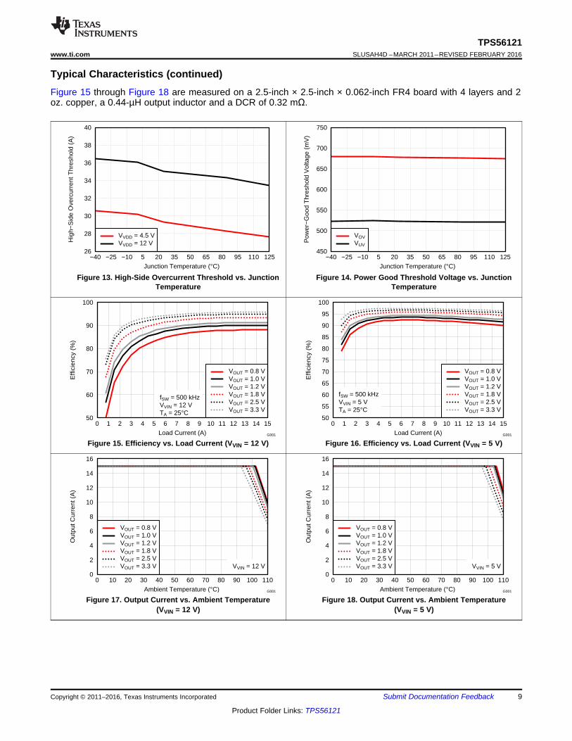
Typical Characteristics (continued)Figure 15 through Figure 18 are measured on a 2.5-inch × 2.5-inch × 0.062-inch FR4 board with 4 layers and 2oz. copper, a 0.44-µH output inductor and a DCR of 0.32 mΩ.
Figure 13. High-Side Overcurrent Threshold vs. JunctionTemperature
Figure 14. Power Good Threshold Voltage vs. JunctionTemperature
Figure 15. Efficiency vs. Load Current (VVIN = 12 V) Figure 16. Efficiency vs. Load Current (VVIN = 5 V)
Figure 17. Output Current vs. Ambient Temperature(VVIN = 12 V)
Figure 18. Output Current vs. Ambient Temperature(VVIN = 5 V)

BOOT
SW
ILIM
EN/SS
COMP
FB
GND
VDD
BP
PGOOD
PAD
VIN
+
+
FB
0.6 VREF + 12.5%
0.6 VREF –12.5%
+
Fault
Controller
SS
Soft StartBP
Anti-Cross
Conduction
and
Pre-Bias
Circuit
PWM
Logic
BP
Clock
6-V
Regulator References 0.6 VREF
SD
BP
Oscillator
+
Calibration
Circuit
+
UDG-11050
0.6 VREF
SS
10 mA
750 kW
Fault Controller
Thermal
Shutdown OC
Threshold
Setting
10 mA
OC
SS
SD
PWM
Clock
OC
TPS56121
10
TPS56121SLUSAH4D –MARCH 2011–REVISED FEBRUARY 2016 www.ti.com
Product Folder Links: TPS56121
Submit Documentation Feedback Copyright © 2011–2016, Texas Instruments Incorporated
7 Detailed Description
7.1 OverviewThe TPS56121 is a 15-A high performance synchronous buck converter with two integrated N-channel NexFETpower MOSFETs. The device implements a voltage-mode control with voltage feed-forward compensation thatresponds instantly to input voltage change. Pre-bias capability eliminates concerns about damaging sensitiveloads.
7.2 Functional Block Diagram
7.3 Feature Description
7.3.1 Voltage ReferenceThe 600-mV bandgap cell is internally connected to the non-inverting input of the error amplifier. The referencevoltage is trimmed with the error amplifier in a unity gain configuration to remove amplifier offset from the finalregulation voltage. The 1% tolerance on the reference voltage allows the user to design a very accurate powersupply.

0
0.4
0.8
1.2
1.6
Input
Voltage
(V)
Time (ms)
2.0
Calibration
Time(1.9 ms)
0.7 V
1.3 V
VSS_INT
VEN/SS
11
TPS56121www.ti.com SLUSAH4D –MARCH 2011–REVISED FEBRUARY 2016
Product Folder Links: TPS56121
Submit Documentation FeedbackCopyright © 2011–2016, Texas Instruments Incorporated
Feature Description (continued)
Figure 19. Startup Sequence and Timing
7.3.2 Enable Functionality, Startup Sequence and TimingAfter input power is applied, an internal 40-μA current source begins to charge the soft-start capacitor connectedfrom EN/SS to GND. When the voltage across that capacitor increases to 0.7 V, it enables the internal BPregulator followed by a calibration. Total calibration time is approximately 1.9 ms. See Figure 19. During thecalibration, the device performs the following two functions.
7.3.2.1 COMP Pin Impedance SensingThe device samples the impedance at the COMP pin and determines the appropriate operating switchingfrequency. If there is no resistor connected from the COMP pin to GND, the switching frequency is set to thedefault value of 500 kHz. If a resistor of 40.2 kΩ ± 10% is connected from the COMP pin to GND, the switchingfrequency is set to 300 kHz. Alternatively, if a resistor of 13.3 K ± 10% is connected from the COMP pin to GND,the switching frequency is set to 1 MHz.
After a 1.1-ms time period, the COMP pin is then brought low for 0.8 ms. This ensures that the feedback loop ispreconditioned at startup and no sudden output rise occurs at the output of the converter when it is allowed tostart switching.
7.3.2.2 Overcurrent Protection (OCP) SettingThe device sources 10 μA (typical) to the resistor connected from the ILIM pin to GND. The voltage developedacross that resistor multiplied by a factor of 2 is then sampled and latched off internally as the OCP trip level forthe low-side FET until one cycles the input or toggles the EN/SS.
The voltage at EN/SS is internally clamped to 1.3 V before and/or during calibration to minimize the dischargingtime once calibration is complete. The discharging current is from an internal current source of 140 μA and itpulls the voltage down to 0.4 V. It then initiates the soft-start by charging up the capacitor using an internalcurrent source of 10 μA. The resulting voltage ramp on this pin is used as a second non-inverting input to theerror amplifier after an 800 mV (typical) downward level-shift; therefore, the actual soft-start does not take placeuntil the voltage at this pin reaches 800 mV.
If the EN/SS pin is left floating, the controller starts automatically. EN/SS must be pulled down to less than 270mV to ensure that the chip is in shutdown mode.
7.3.3 Soft-Start TimeThe soft-start time of the TPS56121 is user programmable by selecting a single capacitor. The EN/SS pinsources 10 μA to charge this capacitor. The actual output ramp-up time is the amount of time that it takes for the10 μA to charge the capacitor through a 600 mV range. There is some initial lag due to calibration and an offset(800 mV) from the actual EN/SS pin voltage to the voltage applied to the error amplifier.

( )P P
OCSET OUT max
IR I 95 62.5
2
-æ öæ ö= - ´ +ç ÷ç ÷
è øè ø
æ ö= ´ç ÷
è ø
SSSS SS
FB
IC t
V
12
TPS56121SLUSAH4D –MARCH 2011–REVISED FEBRUARY 2016 www.ti.com
Product Folder Links: TPS56121
Submit Documentation Feedback Copyright © 2011–2016, Texas Instruments Incorporated
Feature Description (continued)The soft-start is accomplished in a closed-loop, meaning that the error amplifier controls the output voltage at alltimes during the soft-start period and the feedback loop is never open as occurs in duty cycle limit soft-startschemes. The error amplifier has two non-inverting inputs, one connected to the 600-mV reference voltage, andthe other connected to the offset EN/SS pin voltage. The lower of these two voltages is what the error amplifiercontrols the FB pin to. As the voltage on the EN/SS pin ramps up past approximately 1.4 V (800 mV offsetvoltage plus the 600 mV reference voltage), the 600-mV reference voltage becomes the dominant input and theconverter has reached its final regulation voltage.
The capacitance required for a given soft-start ramp time for the output voltage is calculated in Equation 1.
where• CSS is the required capacitance on the EN/SS pin (nF)• ISS is the soft-start source current (10 μA)• VFB is the feedback reference voltage (0.6 V)• tSS is the desired soft-start ramp time (ms) (1)
7.3.4 OscillatorThe oscillator frequency is internally fixed at 500 KHz if there is no resistor connected from COMP pin to GND.Optionally, a 40.2-kΩ resistor from the COMP pin to GND sets the frequency to 300 KHz. Alternatively, a 13.3-kΩresistor from COMP pin GND sets the frequency to 1 MHz.
7.3.5 Overcurrent Protection (OCP)Programmable OCP level at ILIM is from 6 mV to 50 mV. With a scale factor of 2, the actual OC trip point acrossthe low-side FET is in the range of 12 mV to 100 mV.
If the voltage drop across ROCSET reaches 300 mV during calibration (No ROCSET resistor included), it disablesOC protection. Once disabled, there is no low-side or high-side current sensing.
OCP level for the high-side FET is fixed at 34 A (typical). The high-side OCP provides pulse-by-pulse currentlimiting.
OCP sensing for the low-side FET is a true inductor valley current detection, using sample and hold. Equation 2can be used to calculate ROCSET. Since the TPS56121 is designed for 15-A full-Load current and not intentionallydesigned for an OCP level below 10 A, use an ROCSET value above 1 kΩ to get an accurate OCP tripping point.
where• IP-P is the peak-to-peak inductor current (A)• IOUT(max) is the trip point for OCP (A)• ROCSET is the resistor used for setting the OCP level (Ω) (2)
An overcurrent (OC) condition is detected by sensing voltage drop across the low-side FET and across the high-side FET. If the voltage drop across either FET exceeds OC threshold, a count increments one count. If no OCcondition is detected on either FET, the fault counter decrements by one counter. If three OC pulses aresummed, a fault condition is declared which cycles the soft-start function in a hiccup mode. Hiccup mode isdefined as four dummy soft-start timeouts followed by a real one if overcurrent condition is encountered duringnormal operation; or five dummy soft-start timeouts followed by a real one if overcurrent condition occurs fromthe beginning during start. This cycle continues indefinitely until the fault condition is removed.

13
TPS56121www.ti.com SLUSAH4D –MARCH 2011–REVISED FEBRUARY 2016
Product Folder Links: TPS56121
Submit Documentation FeedbackCopyright © 2011–2016, Texas Instruments Incorporated
Feature Description (continued)7.3.6 Switching Node (SW)The SW pin connects to the switching node of the power conversion stage. It acts as the return path for the high-side gate driver. When configured as a synchronous buck stage, the voltage swing on SW normally traversesfrom below ground to well above the input voltage. Parasitic inductance in the high-side FET and the outputcapacitance (COSS) of both power FETs form a resonant circuit that can produce high frequency ( > 100 MHz)ringing on this node. The voltage peak of this ringing, if not controlled, can be significantly higher than the inputvoltage. Ensure that the peak ringing amplitude does not exceed the absolute maximum rating limit for the pin.
In many cases, a series resistor and capacitor snubber network connected from the switching node to PGND canbe helpful in damping the ringing and decreasing the peak amplitude. Provide provisions for snubber networkcomponents in the layout of the printed circuit board. If testing reveals that the ringing amplitude at the SW pinexceeds the limit, then include snubber components.
Placing a BOOT resistor with a value between 5 Ω and 15 Ω in series with the BOOT capacitor slows down theturn-on of the high-side FET and can help to reduce the peak ringing at the switching node as well.
7.3.7 Input Undervoltage Lockout (UVLO)The TPS56121 has fixed input UVLO. In order for the device to turn on, the following conditions must be met:• the EN/SS pin voltage must be greater than VIH• the input voltage must exceed UVLO on voltage VUVLO
The UVLO has a minimum of 500 mV hysteresis built-in.
7.3.8 Pre-Bias StartupThe TPS56121 contains a unique circuit to prevent current from being pulled from the output during startup in thecondition the output is pre-biased. There are no PWM pulses until the internal soft-start voltage rises above theerror amplifier input (FB pin), if the output is pre-biased. Once the soft-start voltage exceeds the error amplifierinput, the controller slowly initiates synchronous rectification by starting the synchronous rectifier with a narrowon time. It then increments the on-time on a cycle-by-cycle basis until it coincides with the time dictated by (1-D),where D is the duty cycle of the converter.
This approach prevents the sinking of current from a pre-biased output, and ensures the output voltage startupand ramp to regulation is smooth and controlled.
7.3.9 Power GoodThe TPS56121 provides an indication that output is good for the converter. This is an open drain signal and pullslow when any condition exists that would indicate that the output of the supply might be out of regulation. Theseconditions include:• VFB is more than ±12.5% from nominal• soft-start is active• a short circuit condition has been detected
NOTEWhen there is no power to the device, PGOOD is not able to pull close to GND if anauxiliary supply is used for the power good indication. In this case, a built in resistorconnected from drain to gate on the PGOOD pull down device makes the PGOOD pinlook approximately like a diode to GND.
7.3.10 Thermal ShutdownIf the junction temperature of the device reaches the thermal shutdown limit of 145°C, both the high-side FETand low-side FET maintain off status. When the junction cools to the required level (125°C typical), the PWMinitiates soft start as during a normal power-up cycle.

14
TPS56121SLUSAH4D –MARCH 2011–REVISED FEBRUARY 2016 www.ti.com
Product Folder Links: TPS56121
Submit Documentation Feedback Copyright © 2011–2016, Texas Instruments Incorporated
7.4 Device Functional ModesThe TPS56121 devices operate in continuous conduction mode (CCM) at a fixed frequency, regardless of theoutput current. For the first 128 switching cycles, the low-side MOSFET on-time is slowly increased to preventexcessive current sinking in the event the device is started with a prebiased output. Following the first 128switching cycles, the low-side MOSFET and the high-side MOSFET on-times are fully complementary.

+
15
TPS56121www.ti.com SLUSAH4D –MARCH 2011–REVISED FEBRUARY 2016
Product Folder Links: TPS56121
Submit Documentation FeedbackCopyright © 2011–2016, Texas Instruments Incorporated
8 Application and Implementation
NOTEInformation in the following applications sections is not part of the TI componentspecification, and TI does not warrant its accuracy or completeness. TI’s customers areresponsible for determining suitability of components for their purposes. Customers shouldvalidate and test their design implementation to confirm system functionality.
8.1 Application InformationThe TPS56121 is a highly-integrated synchronous step-down DC-DC converter. It is used to convert a higher DCinput voltage (4.5 V to 14 V recommended) to a lower DC output voltage (as low as 0.6 V), with a maximumoutput current of 15 A, for a variety of applications.
8.2 Typical ApplicationThis design example describes a 15-A, 12-V to 1.0-V design using the TPS56121 high-current integrated buckconverter. The system specifications are listed in Table 1. Use the following design procedure to select keycomponent values for this device.
Figure 20. Design Example Schematic
8.2.1 Design Requirements
Table 1. TPS56121 Design Example ParametersPARAMETER TEST CONDITIONS MIN TYP MAX UNIT
VIN Input voltage 8 12 14 VVIN(ripple) Input ripple IOUT = 15 A 0.15 VVOUT Output voltage 0 A ≤ IOUT ≤ 15 A 0.98 1.00 1.02 V
Line regulation 8 V ≤ VIN ≤ 14 V 0.1%Load regulation 0 A ≤ IOUT ≤ 15 A 0.5%
VRIPPLE Output ripple IOUT= 15 A 20 mVVOVER Output overshoot ITRAN = 5 A 50 mVVUNDER Output undershoot ITRAN = 5 A 50 mVIOUT Output current 8 V ≤ VIN ≤ 14 V 0 15 AtSS Soft-start time VIN = 12 V 2.0 msIOUT(max) Short- circuit current trip point 20 Aη Efficiency VIN = 12 V, IOUT = 15 A 90%fSW Switching frequency 500 kHz

16
TPS56121SLUSAH4D –MARCH 2011–REVISED FEBRUARY 2016 www.ti.com
Product Folder Links: TPS56121
Submit Documentation Feedback Copyright © 2011–2016, Texas Instruments Incorporated
8.2.2 Detailed Design Procedure
Table 2. List of Materials for TPS56121 Design ExampleREFERENCEDESiGNATOR QTY VALUE DESCRIPTION SIZE PART NUMBER MANUFACTURER
C1, C2, C3, C4 4 22 µF Capacitor, Ceramic, 25 V, X5R, 20% 1210 Std StdC5, C11 2 1.0 µF Capacitor, Ceramic, 25V, X7R, 20% 0805 Std Std
C6 0 100 µF Capacitor, Aluminum, 16 VDC, ±20% Code D8 EEEFP1C101AP PanasonicC7, C8, C9,C10, C19 5 100 µF Capacitor, Ceramic, 6.3V, X5R, 20% 1210 Std Std
C12 1 4.7 µF Capacitor, Ceramic, 10 V, X5R, 20% 0805 Std StdC13 1 33 nF Capacitor, Ceramic, 16 V, X7R, 20% 0603 Std StdC14 1 100 nF Capacitor, Ceramic, 50 V, X7R, 20% 0603 Std StdC15 1 2200 pF Capacitor, Ceramic, 50 V, X7R, 10% 0603 Std StdC16 1 100 pF Capacitor, Ceramic, 50 V, C0G, 5% 0603 Std StdC17 1 680 pF Capacitor, Ceramic, 50 V, C0G, 5% 0603 Std StdC18 1 1000 pF Capacitor, Ceramic, 50 V, X7R, 20% 0603 Std Std
C20, C21 0 100 µF Capacitor, Ceramic, 6.3 V, X5R, 20% 1210 Std Std
J1, J2 2 Terminal Block, 4-pin, 15 A, 5.1 mm 0.80 x 0.35inch ED120/4DS OST
J3 1 Header, Male 2-pin, 100mil spacing 0.100 inch x2 PEC02SAAN Sullins
L1 1 440 nH Inductor, 440 nH, 30A, 0.32 mΩ 0.530 x0.510 inch PA0513.441NLT Pulse
R1 1 1.78 kΩ Resistor, Chip, 1/16W, 1% 0603 Std StdR2 1 5.10 Ω Resistor, Chip, 1/16W, 1% 0603 Std StdR3 1 7.87 kΩ Resistor, Chip, 1/16W, 1% 0603 Std StdR4 1 20.5 kΩ Resistor, Chip, 1/16W, 1% 0603 Std StdR5 1 49.9 Ω Resistor, Chip, 1/16W, 1% 0603 Std StdR6 1 1.00 kΩ Resistor, Chip, 1/16W, 1% 0603 Std StdR7 1 30.1 kΩ Resistor, Chip, 1/16W, 1% 0603 Std StdR8 1 0 Ω Resistor, Chip, 1/16 W, 1% 0603 Std StdR9 1 1.00 Ω Resistor, Chip, 1/8 W, 1% 0805 Std StdR10 1 100 kΩ Resistor, Chip, 1/16W, 1% 0603 Std Std
TP1, TP3, TP11 3 Test Point, Red, Thru Hole 0.125 x0.125 inch 5010 Keystone
TP2, TP4, TP8,TP9, TP12 5 Test Point, Black, Thru Hole 0.125 x
0.125 inch 5011 Keystone
TP5, TP6 2 Test Point, Yellow, Thru Hole 0.125 x0.125 inch 5014 Keystone
TP7, TP10 2 Test Point, White, Thru Hole 0.125 x0.125 inch 5012 Keystone
U1 1 4.5-V to 14-V input, 15-A, synchronousbuck converter
QFN-226 × 5 mm TPS56121DQP TI
8.2.2.1 Switching Frequency SelectionTo achieve a balance between small size and high efficiency for this design, use switching frequency of 500 kHz.
8.2.2.2 Inductor Selection (L1)Synchronous buck power inductors are typically sized for between approximately 20% and 40% peak-to-peakripple current (IP-P).
Using this target ripple current, the required inductor size can be calculated as shown in Equation 3.

( ) ( ) ( ) ( )1 1RIPPLEL _PEAK max OUT max 2 2
I I I 20 A 4.2A 22.1A= + ´ = + ´ =
( ) ( ) ( )1 1OUT RIPPLE CHARGEL peak 2 2
I I I I 15 A 4.2A 0.25 A 17.4 A= + ´ + = + ´ + =
OUT OUTCHARGE
SS
V C 1.0 V 500 FI 0.25 A
t 2ms
´ ´ m= = =
P PRIPPLE
RIPPLE RIPPLE(COUT) OUT SWCOUT(max)
P P P P
I 4.2AV 20mV
V V 8 C f 8 500 F 500kHzESR 4.3m
I I 4.2A
-
- -
æ ö æ ö- -ç ÷ ç ÷- ´ ´ ´ m ´è ø è ø= = = = W
( )
( )
2TRAN
OUT(min)IN OUT UNDER
I LC
V V V
´=
- ´
( )
( )
2 2TRAN
OUT(min)OUT OVER
I L 5 440nHC 220 F
V V 1.0 50mV
´ ´= = = m
´ ´
( ) ( ) ( )( ) ( ) ( )( )2 2 2 21 1
OUT P PL rms 12 12I I I 15 4.2 15.05 A-= + ´ = + ´ =
IN(max) OUT OUT
OUT IN(max) SW
V V V 1 14 V 1.0 V 1.0 V 1L 413nH
0.3 I V f 0.3 15 A 14 V 500kHz
- -
» ´ ´ = ´ ´ =
´ ´
17
TPS56121www.ti.com SLUSAH4D –MARCH 2011–REVISED FEBRUARY 2016
Product Folder Links: TPS56121
Submit Documentation FeedbackCopyright © 2011–2016, Texas Instruments Incorporated
(3)
Selecting a standard 440-nH inductor value, IP-P = 4.2 A.
The RMS current through the inductor is approximated in Equation 4.
(4)
8.2.2.3 Output Capacitor SelectionThe output transient response typically drives the selection of the output capacitor. For applications where VIN(min)> 2 × VOUT, use overshoot to calculate the minimum output capacitance, as shown in Equation 5.
(5)
For applications where VIN(min) < 2 × VOUT, use overshoot to calculate the minimum output capacitance. Theequation is shown in Equation 6
(6)
In order to meet the low ESR and high capacitance requirements, this design uses five 100-µF, 1210 ceramiccapacitors. With a minimum capacitance, maximum ripple voltage determines the maximum allowable ESR. TheESR is approximated in Equation 7.
(7)
8.2.2.4 Inductor Peak Current RatingWith output capacitance, it is possible to calculate the charge current during start-up and determine the minimumsaturation current rating for the inductor. Equation 8 approximates the start-up charging current (ICHARGE).
(8)
Equation 9 approximates the peak current in the inductor, IL(peak).
(9)
With the short circuit current trip point IOUT(max) set at 20 A, the maximum allowable peak current IL_PEAK(max) isshown in Equation 10.
(10)
The selection of output capacitor meets the maximum allowable peak current requirement.
Table 3. Inductor Requirements SummaryPARAMETER VALUE UNIT
L Inductance 440 nHIL(rms) RMS current (thermal rating) 15.1 AIL_PEAK(max) Peak current (saturation rating) 22.1 A

SSSS SS
FB
I 10 AC t 2.0ms 33nF
V 0.6 V
m= ´ = ´ =
( ) ( )OUT MAX MAX rmsRMS cin
1 1I I D 1 D 15 A 1 5.0 A
8 8
æ ö= ´ ´ - = ´ ´ - =ç ÷
è ø
( )IN_RIPPLE(ESR)
CIN maxP P
OUT
V 50mVESR 2.9m
I 4.2A15 AI
22-
= = = Wæ ö æ ö++ ç ÷ç ÷ è øè ø
( )
( )
( )
( )
OUT OUT IN(min) OUTIN(min) 2 2
IN_RIPPLE(CAP) IN(min) SW
I V V V 15 1.0 V 8 V 1.0 VC 32.8 F
100mV 8 V 500kHzV V f
´ ´ - ´ ´ -= = = m
´ ´´ ´
18
TPS56121SLUSAH4D –MARCH 2011–REVISED FEBRUARY 2016 www.ti.com
Product Folder Links: TPS56121
Submit Documentation Feedback Copyright © 2011–2016, Texas Instruments Incorporated
Thie design uses a PA0513.441NLT, 440-nH, 0.32-mΩ, 30-A inductor.
8.2.2.5 Input Capacitor SelectionThe input voltage ripple is divided between capacitance and ESR. For this design VIN_RIPPLE(CAP) = 100 mV andVIN_RIPPLE(ESR) = 50 mV. Use Equation 11 to estimate the minimum capacitance. Use Equation 12 to estimate themaximum ESR.
(11)
(12)
Equation 13 estimates the RMS current in the input capacitors.
(13)
Four 1210, 22-µF, 25-V, X5R, ceramic capacitors with approximately 2.5-mΩ ESR and a 2.5-A RMS currentrating are selected. Higher voltage capacitors are selected to minimize capacitance loss at the DC bias voltage toensure the capacitors will have sufficient capacitance at the working voltage while a 1.0-µF capacitor in smallercase size is used to reduce high frequency noise from the MOSFET switching.
8.2.2.6 Bootstrap Capacitor (C14)The bootstrap capacitor maintains power to the high-side driver during the high-side switch ON time. Per therequirements of the integrated MOSFET, the value of CBOOT is 100 nF with a minimum 10-V rating.
8.2.2.7 Bootstrap Resistor (R2)The bootstrap resistor slows the rising edge of the SW voltage to reduce ringing and improve EMI. Per thedatasheet recommendation a 5.1-Ω resistor is selected.
8.2.2.8 RC Snubber (R9 and C18)To effectively limit the switch node ringing, select a 1.0-Ω resistor and a 1000-pF capacitor
8.2.2.9 VDD Bypass Capacitor (C11)Per the data sheet recommended pin terminations, bypass VDD to GND with a 1.0-µF capacitor.
8.2.2.10 BP5 Bypass Capacitor (C12)Per the data sheet recommended pin functions, bypass BP5 to GND with a capacitor with a value of at least 1.0-µF. For additional filtering and noise immunity, select a 4.7-µF capacitor.
8.2.2.11 Soft-Start Capacitor (C13)The soft-start capacitor provides a constant ramp voltage to the error amplifier to provide controlled, smoothstart-up. The soft-start capacitor is sized using Equation 14.
(14)
8.2.2.12 Current Limit (R1)The TPS56221 uses the negative drop across the internal low-side FET at the end of the OFF-time to measurethe valley of the inductor current. Allowing for a minimum 20-A, or 30% over maximum load, the programmingresistor is selected using Equation 15.

( ) ( )FB
OUT FB
V R4 0.600 V 20.5kR7 30.8k
V V 1.0 V 0.600 V
´ ´ W= = = W
- -
P POCSET OUT(max)
I 4.2 AR 95 I 62.5 95 20 A 62.5 1.76 k
2 2
-æ ö æ öæ ö æ ö= ´ - + W = ´ - + W = Wç ÷ ç ÷ç ÷ ç ÷
è øè ø è øè ø
19
TPS56121www.ti.com SLUSAH4D –MARCH 2011–REVISED FEBRUARY 2016
Product Folder Links: TPS56121
Submit Documentation FeedbackCopyright © 2011–2016, Texas Instruments Incorporated
(15)
Select a standard 1.78-kΩ resistor from the E-48 series.
8.2.2.13 Feedback Divider (R4, R7)The TPS56121 converter uses a full operational amplifier with an internally fixed 0.600-V reference. R4 isselected between 10 kΩ and 50 kΩ for a balance of feedback current and noise immunity. With R4 set to 20.5kΩ, program the output voltage with a resistor divider as calculated in Equation 16.
(16)
Select a standard 30.1-kΩ resistor from the E-48 series.
8.2.2.14 Compensation (C15, C16, C17, R3, R6)Using the TPS40k Loop Stability Tool for 50 kHz of bandwidth and 60 degrees of phase margin with an R4 valueof 20.5 kΩ, the design yields the following values.• C17 = C_1 = 680 pF• C15 = C_2 = 2200 pF• C16 = C_3 = 100 pF• R6 = R_2 = 1.00 kΩ• R3 = R_3 = 7.87 kΩ

50
55
60
65
70
75
80
85
90
95
0 3 6 9 12 15Load Current (A)
Effi
cien
cy (
%)
VIN = 8 VVIN = 12 VVIN = 14 VfSW = 500 kHz
G001
1000 10000 100000 400000−60
−50
−40
−30
−20
−10
0
10
20
30
40
−200
−160
−120
−80
−40
0
40
80
120
160
200
Frequency (kHz)
Gai
n (d
B)
Pha
se (
°)
GainPhase
G001
20
TPS56121SLUSAH4D –MARCH 2011–REVISED FEBRUARY 2016 www.ti.com
Product Folder Links: TPS56121
Submit Documentation Feedback Copyright © 2011–2016, Texas Instruments Incorporated
8.2.3 Application CurvesOutput voltage 12 V to 1.0 V at 0-A to 15-A input current.
Figure 21. Efficiency vs Load Current Figure 22. Loop Response, 47-kHz Bandwidth,48° Phase Margin
Figure 23. Output Ripple 20 mV/div, 1.0 µs/div, 20 MHz Bandwidth, AC Coupled

TI
EXAS
NSTRUMENTS
21
TPS56121www.ti.com SLUSAH4D –MARCH 2011–REVISED FEBRUARY 2016
Product Folder Links: TPS56121
Submit Documentation FeedbackCopyright © 2011–2016, Texas Instruments Incorporated
9 Power Supply RecommendationsThe TPS56121 devices are designed to operate from an input voltage supply between 4.5 V and 14 V. Thissupply must be well regulated. These devices are not designed for split-rail operation. The VIN and VDDterminals must be the same potential for accurate high-side short circuit protection. Proper bypassing of inputsupplies and internal regulators is also critical for noise performance, as is PCB layout and grounding scheme.See the recommendations in Layout Guidelines.
10 Layout
10.1 Layout Guidelines• Place input capacitors next to the VIN pin and on the same side as the device. Use wide and short traces or
copper planes for the connection from the VIN pin to the input capacitor and from the input capacitor to thepower pad of the device.
• Place the BP decoupling capacitor close to the BP pin and on the same side as the device in order to avoidthe use of vias. Use wide and short traces for the connection from the BP pin to the capacitor and from thecapacitor to the power pad. If vias are not evitable, use at least three vias to reduce the parasitic inductance.
• Include a Kelvin VDD connection, or separate from VIN connection (bypass input capacitors); add aplaceholder for a filter resistor between the VDD pin and the input bus. Place the VDD decoupling capacitornear the VDD pin and on the same side as the device to avoid the use of vias. Use wide and short traces forthe connection from the VDD pin to the capacitor and from the capacitor to the power pad of the device. Ifvias are not avoidable, use at least three vias to reduce the parasitic inductance.
• Maintain the FB trace away from BOOT and SW traces.• Minimize the area of switch node.• Use a single ground.Do not use separate signal and power ground.• Use 3 × 7 thermal vias as suggested in Land Pattern Data in Mechanical, Packaging, and Orderable
Information.
10.2 Layout ExampleThe TPS56121EVM-601 layout is shown in Figure 24 through Figure 29 for reference.
Figure 24. TPS56121EVM-601 Top AssemblyDrawing (Top view)
Figure 25. TPS56121EVM-601 Bottom AssemblyDrawing (Bottom view)

22
TPS56121SLUSAH4D –MARCH 2011–REVISED FEBRUARY 2016 www.ti.com
Product Folder Links: TPS56121
Submit Documentation Feedback Copyright © 2011–2016, Texas Instruments Incorporated
Layout Example (continued)
Figure 26. TPS56121EVM-601 Top Copper (TopView)
Figure 27. TPS56121EVM-601 Internal 1 (Top View)
Figure 28. TPS56121EVM-601 Internal 2 (Top View) Figure 29. TPS56121EVM-601 Bottom Copper (TopView)

23
TPS56121www.ti.com SLUSAH4D –MARCH 2011–REVISED FEBRUARY 2016
Product Folder Links: TPS56121
Submit Documentation FeedbackCopyright © 2011–2016, Texas Instruments Incorporated
11 Device and Documentation Support
11.1 Device Support
11.1.1 Third-Party Products DisclaimerTI'S PUBLICATION OF INFORMATION REGARDING THIRD-PARTY PRODUCTS OR SERVICES DOES NOTCONSTITUTE AN ENDORSEMENT REGARDING THE SUITABILITY OF SUCH PRODUCTS OR SERVICESOR A WARRANTY, REPRESENTATION OR ENDORSEMENT OF SUCH PRODUCTS OR SERVICES, EITHERALONE OR IN COMBINATION WITH ANY TI PRODUCT OR SERVICE.
11.2 TrademarksPowerPAD, SWIFT, NexFET are trademarks of Texas Instruments.All other trademarks are the property of their respective owners.
11.3 Electrostatic Discharge CautionThese devices have limited built-in ESD protection. The leads should be shorted together or the device placed in conductive foamduring storage or handling to prevent electrostatic damage to the MOS gates.
11.4 GlossarySLYZ022 — TI Glossary.
This glossary lists and explains terms, acronyms, and definitions.
12 Mechanical, Packaging, and Orderable InformationThe following pages include mechanical, packaging, and orderable information. This information is the mostcurrent data available for the designated devices. This data is subject to change without notice and revision ofthis document. For browser-based versions of this data sheet, refer to the left-hand navigation.

PACKAGE OPTION ADDENDUM
www.ti.com 24-Aug-2018
Addendum-Page 1
PACKAGING INFORMATION
Orderable Device Status(1)
Package Type PackageDrawing
Pins PackageQty
Eco Plan(2)
Lead/Ball Finish(6)
MSL Peak Temp(3)
Op Temp (°C) Device Marking(4/5)
Samples
TPS56121DQPR ACTIVE LSON-CLIP DQP 22 2500 Pb-Free (RoHSExempt)
CU NIPDAU | CU SN Level-2-260C-1 YEAR -40 to 125 TPS56121
TPS56121DQPT ACTIVE LSON-CLIP DQP 22 250 Pb-Free (RoHSExempt)
CU NIPDAU | CU SN Level-2-260C-1 YEAR -40 to 125 TPS56121
(1) The marketing status values are defined as follows:ACTIVE: Product device recommended for new designs.LIFEBUY: TI has announced that the device will be discontinued, and a lifetime-buy period is in effect.NRND: Not recommended for new designs. Device is in production to support existing customers, but TI does not recommend using this part in a new design.PREVIEW: Device has been announced but is not in production. Samples may or may not be available.OBSOLETE: TI has discontinued the production of the device.
(2) RoHS: TI defines "RoHS" to mean semiconductor products that are compliant with the current EU RoHS requirements for all 10 RoHS substances, including the requirement that RoHS substancedo not exceed 0.1% by weight in homogeneous materials. Where designed to be soldered at high temperatures, "RoHS" products are suitable for use in specified lead-free processes. TI mayreference these types of products as "Pb-Free".RoHS Exempt: TI defines "RoHS Exempt" to mean products that contain lead but are compliant with EU RoHS pursuant to a specific EU RoHS exemption.Green: TI defines "Green" to mean the content of Chlorine (Cl) and Bromine (Br) based flame retardants meet JS709B low halogen requirements of <=1000ppm threshold. Antimony trioxide basedflame retardants must also meet the <=1000ppm threshold requirement.
(3) MSL, Peak Temp. - The Moisture Sensitivity Level rating according to the JEDEC industry standard classifications, and peak solder temperature.
(4) There may be additional marking, which relates to the logo, the lot trace code information, or the environmental category on the device.
(5) Multiple Device Markings will be inside parentheses. Only one Device Marking contained in parentheses and separated by a "~" will appear on a device. If a line is indented then it is a continuationof the previous line and the two combined represent the entire Device Marking for that device.
(6) Lead/Ball Finish - Orderable Devices may have multiple material finish options. Finish options are separated by a vertical ruled line. Lead/Ball Finish values may wrap to two lines if the finishvalue exceeds the maximum column width.
Important Information and Disclaimer:The information provided on this page represents TI's knowledge and belief as of the date that it is provided. TI bases its knowledge and belief on informationprovided by third parties, and makes no representation or warranty as to the accuracy of such information. Efforts are underway to better integrate information from third parties. TI has taken andcontinues to take reasonable steps to provide representative and accurate information but may not have conducted destructive testing or chemical analysis on incoming materials and chemicals.TI and TI suppliers consider certain information to be proprietary, and thus CAS numbers and other limited information may not be available for release.
In no event shall TI's liability arising out of such information exceed the total purchase price of the TI part(s) at issue in this document sold by TI to Customer on an annual basis.

PACKAGE OPTION ADDENDUM
www.ti.com 24-Aug-2018
Addendum-Page 2

TAPE AND REEL INFORMATION
*All dimensions are nominal
Device PackageType
PackageDrawing
Pins SPQ ReelDiameter
(mm)
ReelWidth
W1 (mm)
A0(mm)
B0(mm)
K0(mm)
P1(mm)
W(mm)
Pin1Quadrant
TPS56121DQPR LSON-CLIP
DQP 22 2500 330.0 15.4 5.3 6.3 1.8 8.0 12.0 Q1
TPS56121DQPT LSON-CLIP
DQP 22 250 330.0 15.4 5.3 6.3 1.8 8.0 12.0 Q1
PACKAGE MATERIALS INFORMATION
www.ti.com 13-Dec-2017
Pack Materials-Page 1

*All dimensions are nominal
Device Package Type Package Drawing Pins SPQ Length (mm) Width (mm) Height (mm)
TPS56121DQPR LSON-CLIP DQP 22 2500 336.6 336.6 41.3
TPS56121DQPT LSON-CLIP DQP 22 250 336.6 336.6 41.3
PACKAGE MATERIALS INFORMATION
www.ti.com 13-Dec-2017
Pack Materials-Page 2

IMPORTANT NOTICE
Texas Instruments Incorporated (TI) reserves the right to make corrections, enhancements, improvements and other changes to itssemiconductor products and services per JESD46, latest issue, and to discontinue any product or service per JESD48, latest issue. Buyersshould obtain the latest relevant information before placing orders and should verify that such information is current and complete.TI’s published terms of sale for semiconductor products (http://www.ti.com/sc/docs/stdterms.htm) apply to the sale of packaged integratedcircuit products that TI has qualified and released to market. Additional terms may apply to the use or sale of other types of TI products andservices.Reproduction of significant portions of TI information in TI data sheets is permissible only if reproduction is without alteration and isaccompanied by all associated warranties, conditions, limitations, and notices. TI is not responsible or liable for such reproduceddocumentation. Information of third parties may be subject to additional restrictions. Resale of TI products or services with statementsdifferent from or beyond the parameters stated by TI for that product or service voids all express and any implied warranties for theassociated TI product or service and is an unfair and deceptive business practice. TI is not responsible or liable for any such statements.Buyers and others who are developing systems that incorporate TI products (collectively, “Designers”) understand and agree that Designersremain responsible for using their independent analysis, evaluation and judgment in designing their applications and that Designers havefull and exclusive responsibility to assure the safety of Designers' applications and compliance of their applications (and of all TI productsused in or for Designers’ applications) with all applicable regulations, laws and other applicable requirements. Designer represents that, withrespect to their applications, Designer has all the necessary expertise to create and implement safeguards that (1) anticipate dangerousconsequences of failures, (2) monitor failures and their consequences, and (3) lessen the likelihood of failures that might cause harm andtake appropriate actions. Designer agrees that prior to using or distributing any applications that include TI products, Designer willthoroughly test such applications and the functionality of such TI products as used in such applications.TI’s provision of technical, application or other design advice, quality characterization, reliability data or other services or information,including, but not limited to, reference designs and materials relating to evaluation modules, (collectively, “TI Resources”) are intended toassist designers who are developing applications that incorporate TI products; by downloading, accessing or using TI Resources in anyway, Designer (individually or, if Designer is acting on behalf of a company, Designer’s company) agrees to use any particular TI Resourcesolely for this purpose and subject to the terms of this Notice.TI’s provision of TI Resources does not expand or otherwise alter TI’s applicable published warranties or warranty disclaimers for TIproducts, and no additional obligations or liabilities arise from TI providing such TI Resources. TI reserves the right to make corrections,enhancements, improvements and other changes to its TI Resources. TI has not conducted any testing other than that specificallydescribed in the published documentation for a particular TI Resource.Designer is authorized to use, copy and modify any individual TI Resource only in connection with the development of applications thatinclude the TI product(s) identified in such TI Resource. NO OTHER LICENSE, EXPRESS OR IMPLIED, BY ESTOPPEL OR OTHERWISETO ANY OTHER TI INTELLECTUAL PROPERTY RIGHT, AND NO LICENSE TO ANY TECHNOLOGY OR INTELLECTUAL PROPERTYRIGHT OF TI OR ANY THIRD PARTY IS GRANTED HEREIN, including but not limited to any patent right, copyright, mask work right, orother intellectual property right relating to any combination, machine, or process in which TI products or services are used. Informationregarding or referencing third-party products or services does not constitute a license to use such products or services, or a warranty orendorsement thereof. Use of TI Resources may require a license from a third party under the patents or other intellectual property of thethird party, or a license from TI under the patents or other intellectual property of TI.TI RESOURCES ARE PROVIDED “AS IS” AND WITH ALL FAULTS. TI DISCLAIMS ALL OTHER WARRANTIES ORREPRESENTATIONS, EXPRESS OR IMPLIED, REGARDING RESOURCES OR USE THEREOF, INCLUDING BUT NOT LIMITED TOACCURACY OR COMPLETENESS, TITLE, ANY EPIDEMIC FAILURE WARRANTY AND ANY IMPLIED WARRANTIES OFMERCHANTABILITY, FITNESS FOR A PARTICULAR PURPOSE, AND NON-INFRINGEMENT OF ANY THIRD PARTY INTELLECTUALPROPERTY RIGHTS. TI SHALL NOT BE LIABLE FOR AND SHALL NOT DEFEND OR INDEMNIFY DESIGNER AGAINST ANY CLAIM,INCLUDING BUT NOT LIMITED TO ANY INFRINGEMENT CLAIM THAT RELATES TO OR IS BASED ON ANY COMBINATION OFPRODUCTS EVEN IF DESCRIBED IN TI RESOURCES OR OTHERWISE. IN NO EVENT SHALL TI BE LIABLE FOR ANY ACTUAL,DIRECT, SPECIAL, COLLATERAL, INDIRECT, PUNITIVE, INCIDENTAL, CONSEQUENTIAL OR EXEMPLARY DAMAGES INCONNECTION WITH OR ARISING OUT OF TI RESOURCES OR USE THEREOF, AND REGARDLESS OF WHETHER TI HAS BEENADVISED OF THE POSSIBILITY OF SUCH DAMAGES.Unless TI has explicitly designated an individual product as meeting the requirements of a particular industry standard (e.g., ISO/TS 16949and ISO 26262), TI is not responsible for any failure to meet such industry standard requirements.Where TI specifically promotes products as facilitating functional safety or as compliant with industry functional safety standards, suchproducts are intended to help enable customers to design and create their own applications that meet applicable functional safety standardsand requirements. Using products in an application does not by itself establish any safety features in the application. Designers mustensure compliance with safety-related requirements and standards applicable to their applications. Designer may not use any TI products inlife-critical medical equipment unless authorized officers of the parties have executed a special contract specifically governing such use.Life-critical medical equipment is medical equipment where failure of such equipment would cause serious bodily injury or death (e.g., lifesupport, pacemakers, defibrillators, heart pumps, neurostimulators, and implantables). Such equipment includes, without limitation, allmedical devices identified by the U.S. Food and Drug Administration as Class III devices and equivalent classifications outside the U.S.TI may expressly designate certain products as completing a particular qualification (e.g., Q100, Military Grade, or Enhanced Product).Designers agree that it has the necessary expertise to select the product with the appropriate qualification designation for their applicationsand that proper product selection is at Designers’ own risk. Designers are solely responsible for compliance with all legal and regulatoryrequirements in connection with such selection.Designer will fully indemnify TI and its representatives against any damages, costs, losses, and/or liabilities arising out of Designer’s non-compliance with the terms and provisions of this Notice.
Mailing Address: Texas Instruments, Post Office Box 655303, Dallas, Texas 75265Copyright © 2018, Texas Instruments Incorporated


![2N7002BKV 60 V, 340 mA dual N-channel Trench MOSFET · 60 V, 340 mA dual N-channel Trench MOSFET 6. Thermal characteristics Table 6. Thermal characteristics [1] Device mounted on](https://img.pdfslide.us/doc/110x75/5b07051f7f8b9a5c308dc1d0/2n7002bkv-60-v-340-ma-dual-n-channel-trench-mosfet-v-340-ma-dual-n-channel-trench.jpg)