Embed Size (px)
DESCRIPTION
Leica Total Station
Citation preview

10
00
Z0
1
TCA 1800
TPS - System 1000Programs
Version 2.2English
USER
'S M
ANUA
L

2 TPS-System 1000 Programs-2.3.1en © Leica
Congratulations on your purchase of your programsfor a TPS - System 1000 !
In order to use the software correctly and reliably, youmust follow the instructions given in the user manual orin the on-line help system. You must also adhere to thedirections given in the user manual for the product withwhich you are using the software.The rights and responsibilities accruing in respect toLeica as a result of acquisition of the software are setout in the Leica Software License Agreement.To secure your rights with regard to the softwareacquired, it is essential that you follow the directionsgiven on the Leica Software - Support RegistrationCard.

© Leica TPS-System 1000 Programs-2.3.1en 3
Enter your programs' version number in your manualand always refer to this information when you need tocontact your agency or authorized service workshop.
Version number:
TPS - System 1000Programs
Product identification

4 TPS-System 1000 Programs-2.3.1en © Leica
The symbols used in this User's Manual have thefollowing meanings:
DANGER :Indicates an imminently hazardous situation which, ifnot avoided, will result in death or serious injury.
WARNING :Indicates a potentially hazardous situation or anunintended use which, if not avoided, could result indeath or serious injury.
CAUTION :Indicates a potentially hazardous situation or anunintended use which, if not avoided, may result inminor or moderate injury and / or appreciable material,financial and environmental damage.
Important paragraphs which must be adhered to inpractice as they enable the product to be used in atechnically correct and efficient manner.
Symbols used in this Manual

© Leica TPS-System 1000 Programs-2.3.1en 5
Contents 6
Introduction 11
General notes 23
Orientation and Height Transfer 27
Resection 39
Tie Distance 49
Stakeout 59
Free Station 79
Reference Line 93
Remote Height 105
Hidden Point 111
Area (Computation of Area) 117
Sets of Angles 129
Traverse 147
Local Resection 165
Road Line 171
COGO 205
Road Plus 249
File Editor 303
Monitoring 333
Index 341
CO
IN
GN
OH
RE
TD
SO
FS
RL
RH
HP
AR
SA
TR
LR
RO
CG
RP
FE
MO
IX
View of chapters

6 TPS-System 1000 Programs-2.3.1en © Leica
Contents
COIntroduction 11
General 11Installation in the PC 12
Hardware and software required 12Rules for naming files 15
Loading files into the TPS1000 instruments 17Loading system texts 19Loading application programs 20Licence code 21Solving problems 21
General notes 23Units in this manual 23Preparation 23
Settings 23Data exchange 24
Using the program 24Instrument field setup 24Calling up the program 25Designation of keys 26Target eccentricity 26
Orientation and Height Transfer 27Introduction 27Target Point 28
Point List 29Measure Mode 30Calculation 31
More Information 32Plot 34Configuration 35
Configuration Editor 35Dual-face Measurement 37Log file 37
Resection 39Introduction 39Station Data 40Target Point 41Measure Mode 42Calculation 43Configuration 45
Configuration Editor 45Dual-face Measurement 47Log File 47

© Leica TPS-System 1000 Programs-2.3.1en 7
CO
Tie Distance 49Introduction 49Measure Mode 51Results 53Configuration 55
Configuration Editor 55Dual-face Measurement 56Log File 57
Stakeout 59Introduction 59Search Point 59Coarse Positioning 60
Line Offset 60Orthogonal 62Azimuth and Distance 64
Stakeout 66Polar Stakeout 66Orthogonal Stakeout 68Stakeout with auxiliary points 70Stakeout from Coordinate Differences 72
Select Stakeout Method 74Plot 75Configuration 76
Log File 77
Free Station 79Introduction 79Station Data 80Target Point 80
Point List 81Measure Mode 82Calculation 83
More Information 85Plot 87Configuration 88
Configuration Editor 88Dual-face Measurement 90Log File 90
Reference Line 93Introduction 93Baseline Points 95
Determine Base Points 95Measure a Base Point 96
Define Reference Line 98Results Reference Line 99Configuration 101
Configuration Editor 101Log File 103

8 TPS-System 1000 Programs-2.3.1en © Leica
CO
Remote Height 105Introduction 105Measure Base Point 106Measure Remote Point 108Configuration 110
Hidden Point 111Introduction 111Configuration 112Measure Rod 114Results 115
Area (Computation of Area) 117Introduction 117Measure Mode 118
Straight line 118Arcs 120Calculation 123
Plot 124Configuration 125
Configuration Editor 125Dual-face Measurement 126Log File 127
Sets of Angles 129Introduction 129Sets Menu 130
Sets menu - view 130Measure Mode 131
Calculate Mode 135Examples and used formulae 140Configuration 143
Configuration Editor 143Log File 145
Traverse 147Introduction 147Traverse Menu 148
Traverse menu 148New traverse 149Occupy station 153Traverse Point / Sideshot Point 155Close traverse 156
Plot 159Configuration 160
Configuration Editor 160Dual-face Measurement 161Multiple Measurement 161Log File 163

© Leica TPS-System 1000 Programs-2.3.1en 9
CO
Local Resection 165Introduction 165Station Data 166Target Points 167Calculation 168Configuration 169
Configuration Editor 169Dual-face Measurement 170
Road line 171Introduction 171
Program concept 174Alignment 175
Selection of files 175Checking files 176
Program flow 178Chainage and centre-line offset 178Cross sections 180Stakeout 183X-section Check 184
Configuration 188Configuration Editor 188Log File 190
Data format 192Hz-alignment 192
The Road - Data Entry program 204
COGO 205Introduction 205Configuration 207Function selection (COGO Menu) 208Inverse (polar calculation) 209Traverse 212
Defining direction by magnetic bearing 214Defining direction by Azimuth 216Defining horizontal distance 218
Intersections 221Bearing-Bearing Intersection 222Bearing-Distance Intersection 227Distance-Distance Intersection 233
Offsets 237Distance-Offset 238Orthogonal point calculation 241
Three Point Arc 246
Road Plus 249Introduction 249
Alignment Definition 249Data Files 249Creating Data Files 252Program Overview 252

10 TPS-System 1000 Programs-2.3.1en © Leica
CO
Getting Started 253Configuration 254Select Alignment Files 256
Vertical Alignment File 257Horizontal Alignment File 257Cross Section/template File 257Cross Section Assignment File 259Station Equation File 262File Checking 263
Stakeout Using Horizontal Offset 264Preparing for the example 264Select Template point and offset 270Stakeout and Record point 273
Horizontal Offset Stake Out Summary 280Start ROADPLUS & Set Configuration Options 280Select Alignment Files 281Set offset value and select point to stakeout 282Stakeout the point 283Select new chainage 284
Slope Staking 285Reference Point 289
Data Formats 291Horizontal Alignment 291Vertical Alignment 294Cross Sections 296Cross Section Assignments 298Station Equations 300Log File 301
File Editor 303Introduction 303
Creation of files 303Editing files 304
Open file 305Coordinates 306Horizontal Alignment 311Vertical Alignment 317Template 321Station Equation 325Cross-section Assignment 329
Monitoring 333Main menu 335Selecting points 336Measurement menu 337Selecting the points to be measured 338Timer selection 339Point measurement 340End monitoring 340
Index 341

© Leica TPS-System 1000 Programs-2.3.1en 11
IN
The electronic theodolites and total stations in the TPSSystem 1000 are equipped with programs forprocessing field data and control-point coordinates. Thesystems are therefore highly functional and classicalsurvey tasks are simplified appreciably.
When delivered, the instruments are already equippedfor the following standard applications:
- Orientation and height transfer- Resection- Tie distance- Stakeout- Free-station survey (Licence code required)
In addition, the following applications are delivered ondiskette:
- Reference line / building alignment- Remote height- Hidden points- Computation of area- Sets of angles- Traverse- Local resection- Roadline- File Editor- Road Plus- COGO- Monitoring
This list is extended continuously. Find actualinformation in file README.TXT on diskette.
The additional application programs can be loaded intothe instrument, but can only be run as a demonstrationversion in which certain functions are disabled. Fullfunctionality can be obtained with a licence code,available from your Leica agency, where you can alsoobtain information about the newest programs availablein the ongoing applications-software development
Introduction
General

12 TPS-System 1000 Programs-2.3.1en © Leica
IN
project.All installation programs and applications are suppliedon normal 3 1/2" diskettes.
For optimal use of the programs and instruments readthis manual carefully.
The hardware and software used to transfer theindividual program packages must meet the followingrequirements:• IBM-compatible PC, 386 or higher• 4 MB RAM• 3.5" floppy-disk drive• RS 232 interface, including interface cable for Leica
survey instruments (stock no. 563625)• MS DOS 5.0 or higher• MS Windows 3.1
Four diskettes are supplied with each instrument:• disk 1 = SYSTEM FIRMWARE• disk 2 = Programs and Languages• disk 3 = TPS-WORKBENCH• disk 4 = RCS 1000
More information can be found in the fileREADME.TXT on each diskette.
Recommended installation procedure:
1. TPS-WORKBENCH (disk 3)2. SYSTEM FIRMWARE (disk 1)3. Programs and languages (disk 2)4. RCS 1000 (disk 4)
Hardware and softwarerequired
Installation in the PC

© Leica TPS-System 1000 Programs-2.3.1en 13
IN
On the diskette bearing the label
TPS 1000/2000/5000TPS-WORKBENCH
is the PC software needed to install applications orforeign-language texts on the TPS1000 instruments.
Exit F3
Pause
Continue
Exit
Directory...ü
ü
ü
ü
ü
Install to:C:\LEICA.WB
Installation Options:TPS Software Upload 378 KBRCS 1000 Controller Upload 57 KBTPS Code Development 157 KBSoftware Radio Configuration 123 KBTPS PC to MC / MC to PC 277 KB
Installation Drive: C:Space Required: 1697 KBSpace Available: ...... KB
Installation TPS
Workbench TPS Tools 2.21Installation
The "WORKBENCH " program is installed in the PCby running the program "SETUP.EXE" underWINDOWS on the diskette. For further details, refer tothe handbook or to the HELP file of WINDOWS.
TPS-user just have to install the "TPS SoftwaeUpload".

14 TPS-System 1000 Programs-2.3.1en © Leica
IN
The diskette bearing the label
TPS 1000SYSTEM FIRMWARE
contains the necessary system software for the TPS1000 instrument:• theodolite system software• ATR system software• EDM system software
The diskette bearing the label
TPS 2000/5000SYSTEM FIRMWARE
contains the necessary system software for theTPS2000/5000 instrument:• theodolite system software• ATR system software• EDM system software
The diskette bearing the label
TPS 1000/2000/5000Programs and Languages
contains:• all applications (both the standard ones and the
additional ones),• the appropriate text files for the languages available.
The text for the languages available are also includedfor the TPS1000 system software.
The diskette bearing the label
TPS 1000/2000/5000RCS 1000
contains the remote control software:• for RCS 1000 based on CR233/333• for RCS 1000 based on GPC1

© Leica TPS-System 1000 Programs-2.3.1en 15
IN
The files are named in accordance with the followingrules:
Application programs: ?????VVV.PRG
????? Maximum of 5 characters for name ofapplication
VVV 3 characters for version (release) numberPRG Identification tag for loadable application
Text files: ?????VVV.LSS
????? identical name of relevant applicationVVV identical version (release) number of relevant
applicationL Identification tag for text file of application
SS Identification tag for languageSS => EN English
GE GermanFR FrenchSP Spanish
System texts:SYS?_VVV._SS
SYS?_ Seven text files (SYS1_ ... SYS7_)VVV Version (release) number of system texts
Identification tag for text file of systemSS Identification tag for language
SS => GE GermanFR FrenchSP Spanish
Rules for naming files

16 TPS-System 1000 Programs-2.3.1en © Leica
IN
After the installation is complete, you will find thefollowing files in the subdirectory in your PC:
Standard applications
Application File name Text file Remarks
All prtxtVVV.LENprtxtVVV.LGEprtxtVVV.LFRprtxtVVV.LSP
Texts commonto all
applications
Orientation andheight transfer
ORI__VVV.PRG ORI__VVV.LENORI__VVV.LGEORI__VVV.LFRORI__VVV.LSP
EnglishGermanFrenchSpanish
Tie distance TIE__VVV.PRG TIE_VVV.LENetc.
Resection RESECVVV.PRG RESECVVV.LENetc.
Stakeout STAKEVVV.PRG STAKEVVV.LENetc.
Additional applications
Application File name Text file Stock no.
Free-station survey FREE_VVV.PRG FREE_VVV.LEN etc. 663156
Reference line /building alignment
REFL_VVV.PRG REFL_VVV.LEN etc. 663198
Hidden points HDNPTVVV.PR HDNPTVVV.LEN etc. 663213
Remote height REMHTVVV.PR REMHTVVV.LEN etc. 663200
Traverse TRAV_VVV.PRG TRAV_VVV.LEN etc. 663197
Computation of areaAREA_VVV.PRG AREA_VVV.LEN etc. 663196
Sets of angles SETS_VVV.PRG SETS_VVV.LEN etc. 663199
Local Resection LRES_VVV.PRG LRES_VVV.LEN etc. 663267
Road Line ROADLVVV.PR ROADLVVV.LEN etc. 663216
File Editor FILEDVVV.PRG FILEDVVV.LEN etc. 663217
Road Plus RPLUSVVV.PRG RPLUSVVV.LEN etc. 663218
COGO COGO_VVV.PRG COGO_VVV.LEN etc. 664401
Monitoring MONIT222.PRG MONIT222.LEN etc. 664411

© Leica TPS-System 1000 Programs-2.3.1en 17
IN
Loading files into theTPS1000 instruments
Applications, and system- and application texts, areloaded into the TPS1000 by means of the "TPSSOFTWARE UPLOAD" program.
Use the interface cable 563 625 to connect theTPS1000 to the serial interface COM1 or COM2 on thePC.
Start the "TPS SOFTWARE UPLOAD" program with adouble-click from the WINDOWS program manager.
Select the command "Sensor/Settings" and inspect theinterface selected and the baud rate. The baud rateshould be set to the maximum. The baud rate for theTPS1000 instrument is set automatically.
TPS 1000 Settings
Baudrate4800
9600
19200
OK
Cancel
Help
COM-Port:
COM1

18 TPS-System 1000 Programs-2.3.1en © Leica
IN
Switch the instrument off! Select the command "ViewApplications + System" to inspect the connection to theinstrument. The instrument switches itself on again andestablishes the connection. The display of theapplications available on the instrument shows that theconnection was successful. If it was not successful, readsection "Solving problems".
View Applications & System
Close Help
General Environment Applications
Name Art.No. Licence CodeVersion Language
FreeSt_Ori_Res 663156 <none>V 2.20 ENGLISH
—TieDistance 663152 <none>V 2.20 ENGLISH
—Stakeout 663155 <none>V 2.20 ENGLISH
—

© Leica TPS-System 1000 Programs-2.3.1en 19
IN
Loading system texts
Afterwards, enter the language on the instrument (seesection "Configuration" of "System" - user manual).
The English system texts are part of the system softwareand can be neither loaded nor erased.
Transfer
Transfer
Cancel
Settings ...
Help
Directories:
i:\software\tps1000\V_2_20
i:\softwaretps1000V_2_20
Drives:
i:
Component Type
System Software
System Language
Application Program
EDM/ATR Firmware
Language:
ENGLISH-T
Components:
System Language (ENGLISH-T Version 2.20)
ü
- Select the command "Transfer files" in the "Utilities"menu ,
- Mark "System Language",- select relevant drive under "Directories",- select desired language under "Language" and- mark relevant file under "Components".
Then press the Transfer key to start the transfer.
The progress of the transfer is shown in a bar diagram.

20 TPS-System 1000 Programs-2.3.1en © Leica
IN
Loading applicationprograms
- Select the command "Transfer files" in the "Utilities"menu ,
- Mark "Application Program",- select relevant drive under "Directories",- select desired language under "Language" and- mark desired program(s) under "Components".
Then press the Transfer key to start the transfer.
The progress of the transfer is shown in a bar diagram.
Transfer
Transfer
Cancel
Settings ...
Help
ü
Directories:
i:\software\tps1000\V_2_20
i:\softwaretps1000V_2_20
Drives:
i:
Component Type
System Software
System Language
Application Program
EDM/ATR Firmware
Language:
ENGLISH-T
Components:
TPS-Application Area (V2.20)TPS-Application COGO (V2.20)TPS-Application FreeSt_Ori_Res (V2.20)TPS-Application HiddenPoint (V2.20)TPS-Application LocalRes (V2.20)TPS-Application RefLine (V2.20)
It is absolutely necessary that the program files(*.prg) are be in the same directory as the languagefiles (*.LSS) and the Prtxt220.LSS file.

© Leica TPS-System 1000 Programs-2.3.1en 21
IN
Licence code When an additional application is first started up, alicence code is requested, so that the application will befully functional. Without this licence code, you can runthe applications as a demonstration version, but you willnot be able to calculate and store the results.
The licence code is available from your Leica agency,who will inform you about licence fees for additionalapplications. Details of the licence agreement are givenin the registration card, which is a part of the "System"manual.To expedite formalities, please fill in a copy of the format the end of this section and fax it to your local Leicaagency.
Solving problems 1. Instrument does not switch on when "Utilities/ViewApplications + System..." option is selected.Inspect the cable connections and that the serialinterface COM1 or COM2 has been set correctly.
2. Instrument does not switch to "ON-LINE-MODE(GeoCOM)" mode when "Utilities/ViewApplications + System..." option is selected.Make sure that the instrument is switched off beforethe "Utilities/View Applications + System..." optionis activated.
3. Instrument does not switch to "ON-LINE-MODE(GeoCOM)" mode when "Utilities/ViewApplications + System..." option is selected;"MEASURE & RECORD" menu or another autostartapplication is displayed instead.

22 TPS-System 1000 Programs-2.3.1en © Leica
IN
Carry out the following operations on the instrument:
until main menu is displayed.
[CONF] Configuration
[Autostart] Autoexec-application
[LIST] and select "MAIN MENU"
Switch off the instrument and start the data transferprocess from the beginning.
or

© Leica TPS-System 1000 Programs-2.3.1en 23
IN
Put crosses against the applications you require and send the form to your nearestLeica agency, which will process your order.
Leica Geosystems AGGeodesy
CH-9435 Heerbrugg(Switzerland)
Software Management Dept.Phone +41 71 727 36 81
Fax +41 71 727 47 05
Address of customer (please use Company stamp or write legibly)
(Company stamp, signature)
To be filledin byagency andforwardedto LeicaGeosystemsAG,Heerbrugg.
We confirm taking outa licence for theapplications listedabove, and weguarantee to pay thelicence fees to LeicaGeosystems AG.
Name
Company
Street
Zip code / City
Country
Telephone
Telefax
Remarks (Company stamp, signature)
Licence code for TPS 1000 applicationsSerial number TPS1000 Instrument type
Name of application No. of application Licence code Remarks
Free station survey 663156
Computation of area 663196
Traverse 663197
Reference line/buildingalig.
663198
Sets of angles 663199
Remote height 663200
Hidden points 663213
Local resection 663267
Road Line 663216
File Editor 663217
Road Plus 663218
COGO 664401
Monitoring 664411

© Leica TPS-System 1000 Programs-2.3.1en 23
EL
GN
General notes
Settings To avoid temporarily-stored information being lostwhen the TPS1000 automatically switches off after longperiods of disuse, you should set the "sleep mode"instead of the automatic switchoff. For moreinformation, please refer to section "Fixed keys"("Power off, Sleep") of "System" - user manual.
Each application takes over the settings (units,recording format, display format etc.) allocated to theappropriate user.
Specifications within this manual always apply to thefollowing units:
Units of length:- in m (meters)- in addition, within brackets in ft (feet)
Units of angle:- in ° ' "- in addition, within brackets in gon
Units of temperature:- in °C- in addition, within brackets in °F
Units in this manual
Preparation All program sequences are based on a unified structure.The clearly-designed display with the function keysmakes learning easy. Each program has a configurationdialog. In this dialog, the user can match program-specific parameters to changes in requirements andsequences. The various possibilities are described in theinstructions for the individual programs.

24 TPS-System 1000 Programs-2.3.1en © Leica
EL
GNData exchange If the settings in an application are altered, these
changed values will be taken over in the otherapplications also and in „Measure and record“. Thesettings affected are the station coordinates and thecircle orientation, along with parameters such as thereflector constant, reflector height, and data for distancereduction. This data can be altered in every application.
The measurement data is stored in the file selected.
If required, these user settings must be defined inadvance. For more information, please refer to section"User configuration" of "System" - user manual.
Using the program
Instrument field setup
The setup is called up in the main menu.
To start with, the user profile and the file for storingmeasurement data can be selected in the start-updisplay.
F1 F2 F3 F4 F5 F6
14:03
QSET STN LIST
SETUP\ START-UP DISPLAY
HELP
Select user template & filesUser templ. : Polar(Standard)Rec. device : Memory CardMeas. file : 1 √ FILE01.GSIData file : 2 √ FILE02.GSI

© Leica TPS-System 1000 Programs-2.3.1en 25
EL
GN
Calling up the program The applications are called up in the main menu.
Select the application required and
confirm
or
alternatively type in the number which appears after theprogram name in the display.
...
MAIN MENU: PROGRAMS 14:03
EXTRA CAL CONF DATA SETUP MEAS
F1 F2 F3 F4 F5 F6
Orientation & Ht. Transfer 00Resection 01Stakeout 02Tie Distance 03Free Station 04
HELP
The dialog enables station coordinates to be set orimported and also permits a direction to a tie point to beset.
SETUP\ STATION DATA 14:03
REC Hz0 IMPOR αNUM
F1 F2 F3 F4 F5 F6
HELP
MCStation no. : STATION 12
Inst.Height : 1.634 mStat.Easting: 1010.567 mStat.Northg : -34213.077 mStat.Elev. : 345.655 mHz : 390°35'58"
The station number, the coordinates, the direction of theline of sight, and the instrument height, are all displayed
26 TPS-System 1000 Programs-2.3.1en © Leica
EL
GN
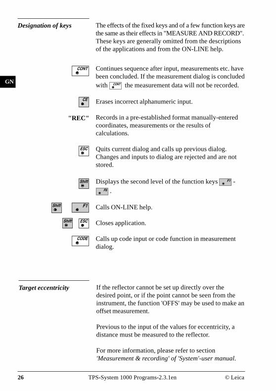
The effects of the fixed keys and of a few function keys arethe same as their effects in "MEASURE AND RECORD".These keys are generally omitted from the descriptionsof the applications and from the ON-LINE help.
Designation of keys
Continues sequence after input, measurements etc. havebeen concluded. If the measurement dialog is concludedwith the measurement data will not be recorded.
Erases incorrect alphanumeric input.
If the reflector cannot be set up directly over thedesired point, or if the point cannot be seen from theinstrument, the function 'OFFS' may be used to make anoffset measurement.
Previous to the input of the values for eccentricity, adistance must be measured to the reflector.
For more information, please refer to section'Measurement & recording' of 'System'-user manual.
Records in a pre-established format manually-enteredcoordinates, measurements or the results ofcalculations.
Quits current dialog and calls up previous dialog.Changes and inputs to dialog are rejected and are notstored.
Displays the second level of the function keys -
.
Calls ON-LINE help.
Closes application.
Calls up code input or code function in measurementdialog.
"REC"
Target eccentricity

© Leica TPS-System 1000 Programs-2.3.1en 27
OH
This manual describes the "Orientation and HeightTransfer" program of the TPS SYSTEM 1000theodolite series.
The instrument must be set up on a known point. Theprogram "ORIENTATION" calculates an angularcorrection for the instruments horizontal circle, so that0.0000 of the horizontal circle corresponds with gridnorth (Orientation correction), using reference pointswith known Easting and Northing.
For simultaneous determination of the station elevation,height of instrument and height of reflector mustalready have been input and the elevation of the targetpoints must be known.
The program handles a maximum of 10 points.
Orientation and Height Transfer
Introduction
E
0°00'00"
H N
PR
OG
_Z
01
E0
N0H0
E
N
H
Hz
∆H

28 TPS-System 1000 Programs-2.3.1en © Leica
OH
Target Point Enter the target point number and height of the reflector.
ORINT\ TARGET POINT 14:03
CALC LIST <-- -->
F1 F2 F3 F4 F5 F6
HELP CONF
MCPoint no. : 12
Refl.Height : 1.300 m
Run the calculation. Note, the key will be assignedafter the first measurement.
Entry of target points into a list as well as selectingpoints for further use.
Displays the previous point from the list of pointsentered. Note that this key will not be available untilthere is at least one point in the list.
Displays the next point in the list of points entered.Note that this key will not be available until there is atleast one point in the list.
Retrieve the coordinates of the target point from theselected file. For further information, please refer todialog "IMPORT" described in the "System" - usermanual.
Start the "CONFIGURATION"

© Leica TPS-System 1000 Programs-2.3.1en 29
OH
Point List Enter a maximum of 10 points. The same point can beretrieved several times.
ORINT\ POINT LIST 14:03
Point 7 : 7Point 8 : 8Point 9 : 9Point10 : 0
MCPoint 1 : 1
Point 2 : 2Point 3 : 3Point 4 : 4Point 5 : 5Point 6 : 6
F1 F2 F3 F4 F5 F6
HELP
Return to the dialog "Target Point".

30 TPS-System 1000 Programs-2.3.1en © Leica
OH
Measure Mode This dialog is similar to the TPS 1000’s basic "MeasureMode" dialog. Once a measurement is taken, theprogram will return to the dialog "Target Point" toacquire the next point for measuring.If the orientation correction can be calculatedsuccessfully from any of the first measurements, the∆Hz and ∆V values are displayed for further enteredtarget point. Motorized theodolites will automaticallydrive the telescope to the target point.
Simultaneously measure and record data on the activerecording device. Return to the dialog "Target Point".
Measure a distance.
Record the measurement on the active recording device.Return to the dialog "Target Point".
Enter target data. For further information, please referto chapter "Measure & Record" described in the"System" - user manual.
Change the theodolite face.
Call up the CODE function, as described in chapter"Measure & Record" described in the "System" - usermanual.
Exit the program.
Accept the measurement and return to the dialog"Target Point".
ORINT\ MEASURE MODE (GSI) 14:03
ALL DIST REC TARGT
F1 F2 F3 F4 F5 F6
Point no. : 1Hz : 216°55'50"V : 71°16'20"Refl.Height : 1.300 mSlope Dist. : 385.231 m∆Hz : -----
HELP I<>II
MC

© Leica TPS-System 1000 Programs-2.3.1en 31
OH
Calculation Calculates the orientation, the elevation and therespective standard deviations.
ORINT\ RESULTS <ROBUST> 14:03
S.ORI S.HT STORE PLOT MORE
Orientation : 2°12'34"σElevation : 0.010 mσOrient : 0°00'03"
MCStation no. : 10
No. of Pts. : 5Inst.Height : 1.635 mEasting : 2134.234 mNorthing : 4723.365 mElevation : 521.643 m
F1 F2 F3 F4 F5 F6
HELP LSQRS
Station no : Point number assigned to the station
No. of Pts : Number of points measured
Inst.Height : Instrument Height
Easting : Easting of the station entered.
Northing : Northing of the station entered.
Elevation : Calculated elevation of the station
Orientation : Oriented direction
σσσσσ Elevation : Standard deviation of the Elevation
σσσσσ Orient : Standard deviation of the Orientation
Set orientation on the instrument. Note that once thiskey has been pressed it will not be possible toexecute more measurements.
Set station elevation on the instrument. Note that oncethis key has been pressed it will not be possible toexecute more measurements.

32 TPS-System 1000 Programs-2.3.1en © Leica
OH
Record the following results into the active file:
WI 11 Station Point NumberWI 25 Orientation correctionWI 84 Station EastingWI 85 Station NorthingWI 86 Station ElevationWI 87 Last reflector height usedWI 88 Instrument Height
Sketch of the station and the reference points used.
Show the results of individual measurements on thescreen (see dialog "More Information").
Measure more points. The program will recall the"TARGET POINT" dialog.
Select between the "Robust" method and the "Variati-on" method.
More Information Display the residuals of individual measurements. Youcan also disable points from the calculation oforientation or height as well as delete erroneousmeasured points.
ORINT\ MORE INFORMATION 14:03
RECLC <-- --> MEAS DEL NO
2/10Use for HT. : YES Status: ONPoint no. : Point01Error flag : NONE∆ Hz : 0°00'03"∆ Distance : 0.050 m
MC
∆ Height : 0.020 mRefl.Height : 1.555 mEasting : 991.427 mNorthing : 1995.162 mElevation : 402.466 m
F1 F2 F3 F4 F5 F6
HELP
© Leica TPS-System 1000 Programs-2.3.1en 33
OH
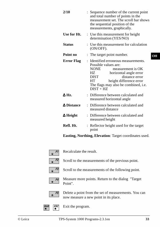
2/10 : Sequence number of the current pointand total number of points in themeasurement set. The scroll bar showsthe sequential position of themeasurements, graphically.
Use for Ht. : Use this measurement for heightdetermination (YES/NO)
Status : Use this measurement for calculation(ON/OFF).
Point no : The target point number.
Error Flag : Identified erroneous measurements.Possible values are:NONE measurement is OKHZ horizontal angle errorDIST distance errorHT height difference errorThe flags may also be combined, i.e.DIST + HZ
∆∆∆∆∆ Hz. : Difference between calculated andmeasured horizontal angle
∆∆∆∆∆ Distance : Difference between calculated andmeasured distance
∆∆∆∆∆ Height : Difference between calculated andmeasured height
Refl. Ht. : Reflector height used for the targetpoint
Easting, Northing, Elevation: Target coordinates used.
Recalculate the result.
Scroll to the measurements of the previous point.
Scroll to the measurements of the following point.
Measure more points. Return to the dialog "TargetPoint".
Delete a point from the set of measurements. You cannow measure a new point in its place.
Exit the program.

34 TPS-System 1000 Programs-2.3.1en © Leica
OH
Plot Generates a plot showing the measurementconfiguration.The station point is in the center and the top of thesketch shows the direction of grid north. The sketch istrue in angular but not true in distances.Points are numbered sequentially in the order in witchthey were measured.Points not used in the calculation are marked with adotted line.
ORINT\ PLOT 14:03
RECLC MEAS
F1 F2 F3 F4 F5 F6
HELP
MC1
54
3
2
Recalculate the result and return to the dialog"CALCULATION RESULTS".
Measure more points. The program will recall the"TARGET POINT" dialog.
Toggle any point ON or OFF by pressing the numerickey corresponding to the sequence number of the point.Note, that
represents point 10
Exit the program.
...

© Leica TPS-System 1000 Programs-2.3.1en 35
OH
Configuration
Configuration Editor
Start the "Configuration Editor" from the "TARGET-POINT" dialog.
ORINT\ CONFIGURATION 14:03
Log FlName : ORIENT.LOG
MCHz Ori Acc : 0°00'32"
Ht Acc TP : 0.0250 mPosn Acc TP : 0.0250 mTwo faces : NOUser Displ : NOLog File : OFFINFO DFLT EDIT
F1 F2 F3 F4 F5 F6
HELP
The "Configuration Editor "sets parameters for furtherprogram operations:
Hz Ori Acc : Limit for the standard deviation of theorientation. The orientation isregarded as "error free", if thecomputed standard deviation of theorientation is within twice the enteredvalue.
Ht Acc TP : Height accuracy of the target points.The entered value, is used as an "apriori" accuracy in the calculation.The height is regarded as "error free",if the computed standard deviation iswithin twice the entered value.

36 TPS-System 1000 Programs-2.3.1en © Leica
OH
Posn Acc TP : Position accuracy of the target points.The entered value, is used as an "apriori" accuracy in the calculation.The position is regarded as "errorfree", if the computed standarddeviation is within twice the enteredvalue.
Two Faces : YES for dual-face measurement,NO for single-face.
User Disp : YES; the measured value indication isused from application "Measure andrecord".NO; the default indication is used for"Orientation and Height Transfer".
Log File : ON, records measurements in a Log-File.The format is described on page37.
Log FlName : Enter the Log File Name.
Displays date and version.
Set the values to default. Default values are shown indialog on page 35.
Exit the program.
Store the current configuration and proceed to thedialog "TARGET POINT".

© Leica TPS-System 1000 Programs-2.3.1en 37
OH
Dual-face Measurement
Log file
In the dual-face mode, the program will prompt formeasurements in both faces. When both measurementsare taken, the program will check the differencebetween the two. If the difference in angle is within 27'(0.5 gon) and the difference of two measured distancesis within 0.5 m (1.64 ft), the observations will beaveraged. These tolerances are used to avoid errors intarget identification. If exceeded an error message willbe displayed.
If "Log File" is set to "ON" the measurements and theresults are stored in the ASCII-file specified within the"Configuration Editor". This file is created in thedirectory LOG on the memory card. Subsequently, youcan read the memory card on your PC and obtain a hardcopy of the Log-file.
Data will always be appended to the specified Log-file.
The Log-file contains the following information:
Header The header line will contain theprogram used, information about theinstrument, the name of the data file aswell as date and time.

38 TPS-System 1000 Programs-2.3.1en © Leica
OH
Leica VIP Orientation + Ht. Transfer V 2.10Instrument : TCM1100, Serial 412160, (not named)User templ. : User 1Meas. file : FILE12.GSIProgram Start : 09/04/1996 at 12:57
Station no. : 2000 E= -0.0006m N= -0.0002m ELV= 398.3961m hi= 1.6000m
Using Robust Solution
Station Elev. : 398.3929mOri.Corr. : 40'36"S.Dev. Elev. : 0.0035mS.Dev. Orient. : 0°00'04"
3 point(s) measured :
## Point no. ∆ Hz ∆ Height ∆ Distance Error Flag1 500 -0°00'55" 0.0026m 0.0020m NONE2 501 -0°00'48" 0.0044m 0.0016m NONE3 502 0°00'52" -0.0070m -0.0000m NONE
Typical log file entry in the "Orientation and Height Transfer" program
Record For each measurement, a record will bestored containing :• Station coordinates• station height,• orientation correction• standard deviations for
height andorientation correction
The residuals for:• horizontal angles,• heights and• measured distancesare also listed.

© Leica TPS-System 1000 Programs-2.3.1en 39
IV
EL
AH
OH
RE
Resection
Introduction This manual describes the "Resection" program of theTPS SYSTEM 1000 theodolite series.
The program can be used to deduce the three-dimensio-nal coordinates for the instrument station and theorientation of the horizontal circle from measurementsto 2 target points with know Easting and Northing. Tocompute the position coordinates, at least the distancesand the directions for both points are necessary.
For simultaneous determination of the station elevation,height of instrument and height of reflector mustalready have been input and the elevation of the targetpoints must be known.
The program allows measurement in single or dual-facemode.
H N
PR
OG
_Z
02
E
H0
0°00'00"
N0
E0
Hz1 Pt1
Pt2
Hz2
D2
D1

IV
EL
AH
OH
RE
40 TPS-System 1000 Programs-2.3.1en © Leica
Station Data Enter station point number and height of the instrument.
RESEC\ STATION DATA 14:03
αNUM
F1 F2 F3 F4 F5 F6
HELP CONF
Station no. : 1Inst.Height : 1.555 m
Proceed to the dialog "Target PoinT"
Start the "Configuration"
MC

© Leica TPS-System 1000 Programs-2.3.1en 41
IV
EL
AH
OH
RE
Target Point Enter the target point number and height of thereflector.
RESEC\ TARGET POINT 14:03
IMPOR αNUM
F1 F2 F3 F4 F5 F6
HELP
Point no. : 30Refl.Height : 1.300 m
MC
Retrieve the coordinates of the point entered from theactive file. For further information, please refer todialog "Import" described in the "System" - usermanual.

IV
EL
AH
OH
RE
42 TPS-System 1000 Programs-2.3.1en © Leica
Measure Mode This dialog is similar to the TPS System1000’s basic"Measure Mode" dialog. Once a measurement is taken,the program will return to the dialog "Target Point" toacquire the next point for measuring.
F1 F2 F3 F4 F5 F6
HELP I<>II
RESEC\ MEASURE MOD (GSI) 14:03Point no. : 1Hz : 286°55'50"V : 91°16'20"Refl.Height : 0.000 mSlope Dist. : ----- m
ALL DIST REC TARGT αNUM
I
MC
Simultaneously measure and record data on the activerecording device. Return to the dialog "TARGETPOINT".
Measure a distance.
Record the measurement on the active recording device.Return to the dialog "TARGET POINT".
Enter target data as described in chapter "Measure &Record" of the "System" - user manual.
Assigned with "aNUM" at point number input; assignedwith "EDIT " at numerical input.
Change the theodolite face.
Call up the CODE function, as described in chapter"Measure & Record" of the "System" - user manual.
Exit the program.
Accept the measurement and return to the dialog"TARGET POINT".

© Leica TPS-System 1000 Programs-2.3.1en 43
IV
EL
AH
OH
RE
Calculation In this dialog the calculated station coordinates areshown with the orientation.
RESEC\CALCULATION RESULTS14:03
SET STORE
Orientation : 2°12'34"σEasting : 0.003 mσNorthing : 0.005 mσElevation : 0.005 mσOrient : 0°00'03"
MCStation no. : 1
No. of Pts. : 2Inst.Height : 1.635 mEasting : 2134.234 mNorthing : 4231.365 mElevation : 580.643 m
F1 F2 F3 F4 F5 F6
HELP
Station no : Station point number
No. of Pts : Number of points measured
Inst.Height : Instrument Height
Easting : Calculated Easting (Y) for the station.
Northing : Calculated Northing (X) for the station.
Elevation : Calculated elevation for the station
Orientation : Oriented direction
σσσσσ Easting : Standard deviation of Easting
σσσσσ Northing : Standard deviation of Northing
σσσσσ Elevation : Standard deviation of the Elevation
σσσσσ Orient : Standard deviation of the Orientation

IV
EL
AH
OH
RE
44 TPS-System 1000 Programs-2.3.1en © Leica
Set orientation and station coordinates on theinstrument. Note that this key will end the program.
Record the following results on the active recordingdevice:
WI 11 Station Point NumberWI 25 Orientation correctionWI 84 Station EastingWI 85 Station NorthingWI 86 Station ElevationWI 87 Last rflector height usedWI 88 Instrument Height
Exit the program.

© Leica TPS-System 1000 Programs-2.3.1en 45
IV
EL
AH
OH
RE
Configuration
Configuration Editor
RESEC\ CONFIGURATION 14:03
INFO DFLT EDIT
Log FlName : RESECT.LOG
MC
F1 F2 F3 F4 F5 F6
HELP
Hz Ori Acc : 0°00'32"Ht Acc TP : 0.025 mPosn Acc TP : 0.025 mTwo Faces : NOUser Displ : NOLog File : OFF
The "Configuration Editor" sets parameters for furtherprogram operations:
Hz Ori Acc : Limit for the standard deviation of theorientation. The orientation isregarded as "error free", if thecomputed standard deviation of theorientation is within twice the enteredvalue.
Ht Acc TP : Height accuracy of the target points.The entered value, is used as an "apriori" accuracy in the calculation.The height is regarded as "error free",if the computed standard deviation iswithin twice the entered value.
Start the "Configuration Editor" from the "STATIONDATA " dialog.

IV
EL
AH
OH
RE
46 TPS-System 1000 Programs-2.3.1en © Leica
Posn Acc TP : Position accuracy of the target points.The entered value, is used as an "apriori" accuracy in the calculation.The position is regarded as "errorfree", if the computed standarddeviation is within twice the enteredvalue.
Two Faces : YES for dual-face measurement,NO for single-face.
Ben.Anzeige : YES; the measured value indication isused from application "Measure andrecord".NO; the default indication is used forthe "Resection".
Log File : Set to ON, the program will recordmeasurement data in a log file asdescribed on page 47.
Log FlName : Enter the Log File Name.
Displays date and version.
Set the value to the default as described in dialog onpage 45.
Exit the program.
Store the current configuration and proceed to thedialog "STATION DATA".

© Leica TPS-System 1000 Programs-2.3.1en 47
IV
EL
AH
OH
RE
Dual-face Measurement In the dual-face mode, the program will prompt formeasurements in both faces. When both measurementsare taken, the program will check the differencebetween the two. If the difference in angle is within 27'(0.5 gon) and the difference of two measured distancesis within 0.5 m (1.64 ft), the observations will beaveraged.These tolerances are used to avoid errors in targetidentification.If exceeded an error message will be displayed.
Log File If "Log File" is set to "ON" the measurements and theresults are stored in the ASCII-file specified within the"Configuration Editor". This file is created in thedirectory LOG on the memory card. Subsequently, youcan read the memory card on your PC and obtain a hardcopy of the Log-file.
Data will always be appended to the specified Log-file.
The Log-file contains the following information:
Header The header line will contain theprogram used, information about theinstrument, the name of the data file aswell as date and time.
Record For each measurement, a record willbe stored containing :Station coordinates and orientationcorrection, standard deviation forEasting, Northing, Height of stationand orientation correction.The residuals for horizontal angles,heights and measured distances arealso listed.

IV
EL
AH
OH
RE
48 TPS-System 1000 Programs-2.3.1en © Leica
Leica VIP Resection V 2.10Instrument : TCM1100, Serial 412160, (not named)User templ. : User 1Meas. file : FILE12.GSIProgram Start : 09/04/1996 at 12:52
Using Least-Squares Solution
Station no. : 2000 E= -0.0011m N= -0.0006m ELV= 398.3951m hi= 1.6000m
Ori.Corr. ; 240°50'51"S.Dev. East : 0.0003mS.Dev. North : 0.0003mS.Dev. Elev. : 0.0047mS.Dev. Orient. : 0°00'49"
2 point(s) measured :
## Point no. ∆ Hz ∆ Height ∆ Distance Error Flag1 500 -0°00'55" 0.0047m 0.0001m NONE2 501 -0°00'18" -0.0047m 0.0002m NONE
Typical log file entry in the "Resection" program

© Leica TPS-System 1000 Programs-2.3.1en 49
IV
EL
AH
OH
BS
TD
Tie Distance
Introduction This manual describes the "Tie Distance" program ofthe TPS SYSTEM 1000 theodolite series.The program calculates the length and azimuth of a lineconnecting two points.Polygonal or Radial methods can be used as shown inthe illustrations.
The data for the points can either be measured orretrieved from the selected file. Measured points andpoints retrieved from the selected file can be usedtogether in the calculations, if the station coordinatesand orientation are set correctly.
In Polygonal Mode, the program will calculate thedistance between the last two points measured (eg. Pt3 -Pt4).
N
PR
OG
_Z
03
E
H
0°00'00"
Pt1Pt2
E0
N0
Hz2Hz3
Slope Dist 1
Slope Dist 3
Slope Dist 2
Hz1
Polygonal Mode
Pt3
Pt4
50 TPS-System 1000 Programs-2.3.1en © Leica
IV
EL
AH
OH
BS
TD
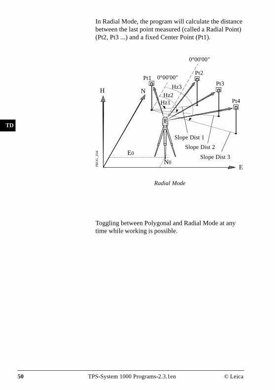
In Radial Mode, the program will calculate the distancebetween the last point measured (called a Radial Point)(Pt2, Pt3 ...) and a fixed Center Point (Pt1).
E
H NP
RO
G_
Z0
4
Pt1Pt2
Pt3
Pt4
Slope Dist 2
Slope Dist 1
Slope Dist 3
Hz3
Hz2Hz1
0°00'00"
Radial Mode
Toggling between Polygonal and Radial Mode at anytime while working is possible.
0°00'00"
E0
N0
© Leica TPS-System 1000 Programs-2.3.1en 51
IV
EL
AH
OH
BS
TD
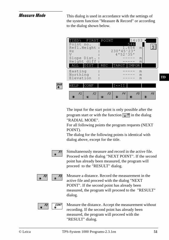
Measure Mode This dialog is used in accordance with the settings ofthe system function "Measure & Record" or accordingto the dialog shown below.
TIED\ FIRST POINT 14:03
ALL DIST REC TARGT IMPOR
Easting : ----- mNorthing : ----- mElevation : ----- m
MCPoint no. : 546
Refl.Height : 1.654 mHz : 230°45'23"V : 4°52'35"Slope Dist. : ----- mHeight diff : ----- m
F1 F2 F3 F4 F5 F6
HELP CONF I<>II
The input for the start point is only possible after theprogram start or with the function in the dialog"RADIAL MODE".For all following points the program requests (NEXTPOINT).The dialog for the following points is identical withdialog above, except for the title.
Simultaneously measure and record in the active file.Proceed with the dialog "NEXT POINT". If the secondpoint has already been measured, the program willproceed to the "RESULT" dialog.
Measure a distance. Record the measurement in theactive file and proceed with the dialog "NEXTPOINT". If the second point has already beenmeasured, the program will proceed to the "RESULT"dialog.
Measure the distance. Accept the measurement withoutrecording. If the second point has already beenmeasured, the program will proceed with the"RESULT" dialog.

52 TPS-System 1000 Programs-2.3.1en © Leica
IV
EL
AH
OH
BS
TD
Enter the target data.For further information refer to chapter "Measure &Record" of "System" - user manual.
Import target coordinates.For further information, please refer to chapter "Setup"of "System" - user manual.
Start the "Configuration Editor".
Change the theodolite face.
Call up the CODE function, as described in chapter"Measure & Record" of "System" - user manual.
Exit the program

© Leica TPS-System 1000 Programs-2.3.1en 53
IV
EL
AH
OH
BS
TD
Results This dialog shows the results computed from the lasttwo points, which can be measured or retrieved fromthe active file. The same results are calculated for bothmethods.
Using "Polygon Mode" the calculations are alwaysbased on the last two points, where as the "RadialMode" always uses the first point as a reference point.
Center Pt. : Point number of the center point
Radial Pt. : Point number of the radial point
Hori.Dist : Horizontal distance between the twopoints
Azimuth : Azimuth from point 1 to point 2
∆∆∆∆∆ Height : Height difference between point 1 andpoint 2 (H
2 - H
1).
Slope Dist : Slope distance between the two points
TIED\ RADIAL MODE 14:03
N.PKT N.ZEN STORE POLYG
∆Easting : 22.432 m∆Northing : 50.083 m
MCCenter Pt. : 12
Radial Pt. : 13Hori.Dist. : 4.567 mAzimuth : 342°52'35"∆ Height : 2.543 mSlope Dist. : 4.946 m
F1 F2 F3 F4 F5 F6
HELP

54 TPS-System 1000 Programs-2.3.1en © Leica
IV
EL
AH
OH
BS
TD
∆∆∆∆∆ Easting : Difference in Easting between point 1and point 2 (E2 - E1).The grid coordinates are only valid fororiented instruments set up on aknown point.
∆∆∆∆∆ Northing : Difference Northing between point 1and point 2 (N
2 - N
1).
Note, the grid coordinates are onlyrelevant for oriented instruments setup on a known point.
Return to the dialog "NEXT POINT" and measure thenext point.
Delete previous inputs. Proceed with the dialog "FIRSTPOINT" to enter a new reference point. This function isavailable for "RADIAL MODE" only.
Record the following results in the active file:
WI 11 Point number of point 2 or radial pointnumber
WI 25 Azimuth from point1 to point 2WI 35 Horizontal distanceWI 37 Height difference between point 1 and
point 2WI 39 Slope distanceWI 79 Point number of point 1 or center point
number
Toggle between Radial/Polygon Mode.

© Leica TPS-System 1000 Programs-2.3.1en 55
IV
EL
AH
OH
BS
TD
Configuration
Configuration Editor
Start the "Configuration Editor" from the "FIRSTPOINT" dialog.
The "Configuration Editor" sets parameters for furtherprogram operations:
Two Faces : Set YES for dual-face measurement,NO for single-face.
User Disp. : YES to use the measurement displayset in the application "Measure &Record".Set NO to use the "Tie Distance"default display.
Log File : Set to ON, the program will recordmeasurement data in the Log Fileaccording to the format described onpage 57.
Log FlName : Enter the Log File Name.
TIED\ CONFIGURATION 14:03
INFO DFLT YES
F1 F2 F3 F4 F5 F6
HELP
MCTwo Faces : NO
User Disp. : NOLog File : OFFLog FlName : TIEDIST.LOG

56 TPS-System 1000 Programs-2.3.1en © Leica
IV
EL
AH
OH
BS
TD
Displays date and version of the running application.
Set the values to default. Default values are displayed indialog on page 55.
Exit the program.
Store the current configuration and proceed to thedialog "MEASURE MODE".
Dual-face Measurement In the dual-face mode, the program will prompt formeasurements in both faces. When both measurementsare taken, the program will check the differencebetween the two. If the difference in angle is within 27'(0.5 gon)) and the difference of two measured distancesis within 0.5 m (1.64 ft), the observations will beaveraged. These tolerances are used to avoid errors intarget identification. If exceeded an error message willbe displayed.
© Leica TPS-System 1000 Programs-2.3.1en 57
IV
EL
AH
OH
BS
TD
Log File If "Log File" is set to ON the measurements and theresults are stored in the ASCII-file specified within the"Configuration Editor". This file is created in thedirectory LOG on the memory card. Subsequently, youcan read the memory card on your PC and obtain a hardcopy of the Log-file.
Data will always be appended to the specified Log-file.
The Log-file contains the following information:
Header The header line will contain theprogram used, information about theinstrument, the name of the data file aswell as date and time.
Record For each measurement, a record willbe stored containing :Point No 1, Point No. 2, Hori. Dist.,Azimuth, ∆Height, Slope Dist.

58 TPS-System 1000 Programs-2.3.1en © Leica
IV
EL
AH
OH
BS
TD
Leica VIP Tie Distance V 2.10Instrument : TCM1100, Serial 412160, (not named)User Templ. : User 1Meas. File : FILE12.GSIProgram Start : 09/04/1996 at 01:13
Station no. : 1151E= 0.0000m N= 0.0000m ELV= 400.0000m hi= 0.0000m
Point No.1 : 1020E= -31.2368m N= -0.2083m ELV= 400.0626m
Point No.2 : 1030E= -30.5679m N= -17.8404m ELV= 403.1198m
Point no.1 : 1020Point no.2 : 1030Hori.Dist. : 17.6448mAzimuth : 197°58'40"
∆Height : 3.0572mSlope dist. : 17.9077m
Point No.2 : 1040E= -57.7040m N= -0.4265m H= 400.1028m
Point No. 1 : 1030Point No.2 : 1040Hori.Dist. : 32.2430mAzimuth : 336°32'14"
∆Height : -3.0170mSlope dist. : 32.3839m
Typical log file entry in the "Tie Distance" program(Polygonal Mode)

© Leica TPS-System 1000 Programs-2.3.1en 59
IV
EL
AH
OH
BS
SM
SO
Stakeout
Introduction This manual describes the "STAKEOUT" program ofthe TPS SYSTEM 1000 theodolite series. The programallows points with known coordinates to be placed inthe field.
"STAKEOUT" requires the instrument to be set up ona known point with the instrument oriented. The stationpoint can be determined also with the programs "FREESTATION " and "RESECTION".The stakeout points can either be retrieved from theselected file or entered manually.The program permits selection of either 2D or 3Dstakeout modes.
Manually enter the stakeout point. The TPS 1000manual input dialog will appear.
Initiate a search of the point in the database.
Allows program configuration.
or
Search Point The "SEARCH POINT" dialog informs about the activerecording device, the active file for data storage and thepresent point/code.
STAKE\ SEARCH POINT 14:03
INPUT SEARC αNUM
F1 F2 F3 F4 F5 F6
HELP CONF
MCDefine stakeout point
Rec. device : Memory CardSearch in : FILE01.GSI
Pkt/Code : 4
60 TPS-System 1000 Programs-2.3.1en © Leica
IV
EL
AH
OH
BS
SM
SO
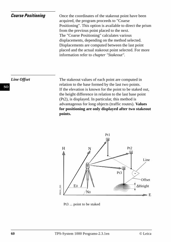
Coarse Positioning Once the coordinates of the stakeout point have beenacquired, the program proceeds to "CoarsePositioning". This option is available to direct the prismfrom the previous point placed to the next.The "Coarse Positioning" calculates variousdisplacements, depending on the method selected.Displacements are computed between the last pointplaced and the actual stakeout point selected. For moreinformation refer to chapter "Stakeout".
Line Offset The stakeout values of each point are computed inrelation to the base formed by the last two points.If the elevation is known for the point to be staked out,the height difference in relation to the last base point(Pt2), is displayed. In particular, this method isadvantageous for long objects (traffic routes). Valuesfor positioning are only displayed after two stakeoutpoints.
PR
OG
_Z
05
N0
H N
Pt1
Pt2
Line
Pt3 ... point to be staked
∆Height
E
Pt3
Offset
E0
© Leica TPS-System 1000 Programs-2.3.1en 61
IV
EL
AH
OH
BS
SM
SO
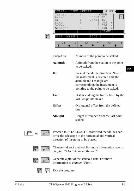
STAKE\ LINE OFFSET 14:03
STAKE
F1 F2 F3 F4 F5 F6
HELP METHD PLOT
MCTarget no. : CURB
Azimuth : 90°10'02"Hz : 98°34'45"Line : 4.105 mOffset : 1.250 m∆Height : 0.340 m
Target no : Number of the point to be staked.
Azimuth : Azimuth from the station to the pointto be staked.
Hz : Present theodolite direction. Note, ifthe instrument is oriented and theazimuth and Hz angle arecorresponding, the instrument ispointing to the point to be staked.
Line : Distance along the line defined by thelast two points staked
Offset : Orthogonal offset from the definedline
∆∆∆∆∆Height : Height difference from the last pointstaked.
Proceed to "STAKEOUT". Motorized theodolites candrive the telescope to the horizontal and verticaldirection of the point to be placed.
Change stakeout method. For more information refer tochapter "Select Stakeout Method".
Generate a plot of the stakeout data. For moreinformation to chapter "Plot".
Exit the program.
or

62 TPS-System 1000 Programs-2.3.1en © Leica
IV
EL
AH
OH
BS
SM
SO
Orthogonal Setting out values are computed as orthogonalcoordinates to the baseline between instrument stationand prism. If the elevation is also known, ∆H is given inrelation to the last prism - point measured.Note, data will be displayed if there is at least one pointmeasured.
PR
OG
_Z
06 E0
H N
EN0
Pt1
STAKE\ORTHOGONAL STAKE 14:03
STAKE
F1 F2 F3 F4 F5 F6
HELP METHD PLOTM
CTarget no. : CURBAzimuth : 90°10'02"Hz : 98°34'45"∆ L : 4.105 m∆ Q : 1.250 m∆Height : 0.340 m
Target no. : Number of the point to be staked.
Azimuth : Azimuth from the station to the pointto be staked.
+∆Q
−∆L
∆H
point to be staked

© Leica TPS-System 1000 Programs-2.3.1en 63
IV
EL
AH
OH
BS
SM
SO
Hz Angle : Present theodolite direction. Note, ifthe instrument is oriented and theazimuth and Hz angle arecorresponding, the instrument ispointing to the point to be staked.
∆∆∆∆∆L and ∆∆∆∆∆Q in relation to the baseline:last stakeout point - instrument station.
∆∆∆∆∆ L : In-line distance ∆∆∆∆∆L is positive forpoints further than the last prismposition measured.
∆ ∆ ∆ ∆ ∆ Q : Distance perpendicular to thebaseline. ∆∆∆∆∆Q is positive for points onthe right of the baseline.
∆∆∆∆∆Height : Height difference from the last pointmeasured.
orProceed to "STAKEOUT". Motorized theodolites candrive the telescope to the horizontal and verticaldirection of the point to be placed.
Change stakeout method.For more information refer to chapter "Select StakeoutMethod".
Generate a plot of the stakeout data.For more information to chapter "Plot".
Exit the program.

64 TPS-System 1000 Programs-2.3.1en © Leica
IV
EL
AH
OH
BS
SM
SO
Azimuth and Distance This method defines the point to be staked in terms ofthe azimuth and distance from the theodolite station tothe point.
STAKE\AZIMUTH & DISTANCE 14:03
STAKE
F1 F2 F3 F4 F5 F6
HELP METHD PLOTM
CTarget no. : CURBAzimuth : 90°10'02"Hz : 98°34'45"Slope Dist. : 4.105 mHoriz.Dist. : 4.021 m∆Height : 0.340 m
Target No. : Number of the point to be staked.
Azimuth : Azimuth from the station to the pointto be staked.
Hz : Present theodolite direction.Note, if the instrument is orientedand the azimuth and Hz angle arecorresponding, the instrument ispointing to the point to be staked.
PR
OG
_Z
07
H N
E
E0
N0
0°00'00"
Azimuth
Slope Dist.
point to bestaked

© Leica TPS-System 1000 Programs-2.3.1en 65
IV
EL
AH
OH
BS
SM
SO
Slope Dist : Slope distance from the instrumentstation to the stakeout point.
Horiz. Dist : Horizontal distance from theinstrument station to the stakeoutpoint.
∆∆∆∆∆ Height : Height difference from the instrumentstation to the stakeout point.
or Proceed to "STAKEOUT". Motorized theodolites candrive the telescope to the horizontal and verticaldirection of the point to be placed.
Change stakeout method.For more information refer to chapter "Select StakeoutMethod".
Generate a plot of the stakeout data. For moreinformation to chapter "Plot".
Exit the program.

66 TPS-System 1000 Programs-2.3.1en © Leica
IV
EL
AH
OH
BS
SM
SO
Stakeout Points must have known coordinates. Various methodscan be used, depending on the Stakeout Method set.Motorized instruments can drive the telescope to thehorizontal and vertical direction of the point to bestaked. For more information refer to chapter "SelectStakeout Method".
STAKE\ POLAR STAKEOUT 14:03
ALL DIST REC TARGT POSIT
F1 F2 F3 F4 F5 F6
HELP METHD PLOT
MCTarget no. : 0025
∆ Hz : 90°10'02"∆ Dist : 4.567 m∆ Height :FILL 0.102 mElevation : 32.543 m
Polar Stakeout After the first distance has been measured, thedifferences between calculated and measured directionand between calculated and measured horizontaldistance are displayed. If the elevation of the point to bestaked is available, the height difference between thelast measured reflector and the point to be staked isshown together with the measured elevation of thereflector point.
PR
OG
_Z
08
E
E0
N0
H N
∆H
Pt1
point to be staked
∆Hz
∆Dist
Values for ∆Hz and ∆D will be updated each time a newdistance is measured.

© Leica TPS-System 1000 Programs-2.3.1en 67
IV
EL
AH
OH
BS
SM
SO
Target no. : Point number of the point to bestaked.
∆ ∆ ∆ ∆ ∆ Hz : Difference in Hz circle readingbetween the actual horizontaldirection and the calculated direction.
∆ ∆ ∆ ∆ ∆ Dist : Difference in horizontal distancebetween the measured and calculateddistance.
∆ ∆ ∆ ∆ ∆ Height : Difference in height between themeasured reflector point and thestakeout point, expressed bothnumerically and as CUT/FILL.
Elevation : Elevation of the measured target point.
Simultaneously measure and record data on the activerecording device.
Measure a distance.
Record the measurement on the active recording device.
Enter target data as described in chapter "Measure &Record" of "System" - user manual.
Re-position the telescope on the target. Note, thisfunction is only available for motorized theodolites.
Change stakeout method. For more information refer tochapter "Select Stakeout Method".
Generate a plot of the stakeout data. For moreinformation refer to chapter "Plot".
Exit the program.
Acquire the next point to stake.
68 TPS-System 1000 Programs-2.3.1en © Leica
IV
EL
AH
OH
BS
SM
SO
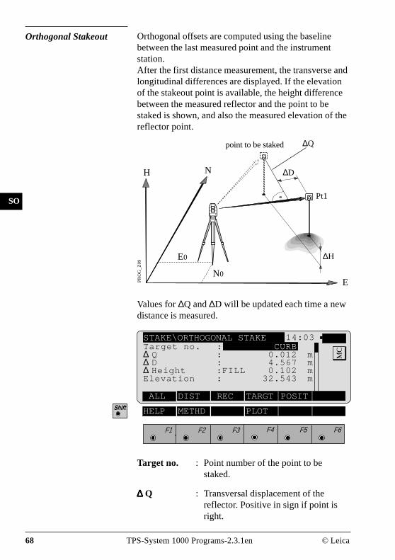
Orthogonal Stakeout Orthogonal offsets are computed using the baselinebetween the last measured point and the instrumentstation.After the first distance measurement, the transverse andlongitudinal differences are displayed. If the elevationof the stakeout point is available, the height differencebetween the measured reflector and the point to bestaked is shown, and also the measured elevation of thereflector point.
Target no. : Point number of the point to bestaked.
∆∆∆∆∆ Q : Transversal displacement of thereflector. Positive in sign if point isright.
STAKE\ORTHOGONAL STAKE 14:03
ALL DIST REC TARGT POSIT
F1 F2 F3 F4 F5 F6
HELP METHD PLOT
MCTarget no. : CURB
∆ Q : 0.012 m∆ D : 4.567 m∆ Height :FILL 0.102 mElevation : 32.543 m
PR
OG
_Z
09
H
EN0
N
E0 ∆H
Pt1
∆D
∆Q
Values for ∆Q and ∆D will be updated each time a newdistance is measured.
point to be staked

© Leica TPS-System 1000 Programs-2.3.1en 69
IV
EL
AH
OH
BS
SM
SO
∆∆∆∆∆ D : Longitudinal displacement of thereflector. Positive in sign if stakeoutpoint is further away from station.
∆ ∆ ∆ ∆ ∆ Height : Difference in height betweenmeasured reflector point and thestakeout point. Positive in sign ifstakeout point is higher than thereflector position.
Elevation : Elevation of the measured reflectorpoint.
Simultaneously measure and record data on the activerecording device.
Measure a distance.
Record the measurement on the active recording device.
Enter target data as described in chapter "Measure &Record" of "System" - user manual.
Re-position the telescope on the target. Note, thisfunction is only available for motorized theodolites.
Change stakeout method. For more information refer tochapter "Select Stakeout Method".
Generate a plot of the stakeout data. For moreinformation refer to chapter "Plot".
Exit the program.
Acquire the next point to stake.

70 TPS-System 1000 Programs-2.3.1en © Leica
IV
EL
AH
OH
BS
SM
SO
Stakeout with auxiliarypoints
The stakeout method computes values for points whichcannot be sighted directly.Measure to the auxiliary point Pt1. The distance "Dist1" and angle "Hz angle 1" to the stakeout point arecomputed. Likewise proceed for auxiliary point Pt2.The stakeout point can be set out using the 2 calculateddistances and/or angles from auxiliary points Pt1 andPt2.The program automatically updates both distance andangle values whenever a new point is measured. Theprevious point Pt2 becomes Pt1 and the new point Ptbecomes Pt2.
Note, the auxiliary point to be measured will be markedwith an asterisk (*).
STAKE\ AUXILIARY POINTS 14:03
ALL DIST REC TARGT POSIT
F1 F2 F3 F4 F5 F6
HELP METHD PLOT
MCTarget no. : CURB
Hz Angle 1 :* 90°01'02"Dist 1 :* 4.567 mHz Angle 2 : 150°22'34"Dist 2 : 2.973 m∆Height :CUT -0.102 m
PR
OG
_Z
10
EN0
Hz2
H N
E0
Dist1
Pt1
Pt2
Dist2
Hz1
point to bestaked
Target no : Point number of the point to bestaked.

© Leica TPS-System 1000 Programs-2.3.1en 71
IV
EL
AH
OH
BS
SM
SO
Hz Angle 1 : Angle from the first auxiliary point tothe stakeout point.
Dist 1 : Distance from the first auxiliary pointto the stakeout point.
Hz Angle 2 : Angle from the second auxiliary pointto the stakeout point.
Dist 2 : Distance from the second auxiliarypoint to the stakeout point.
∆∆∆∆∆ Height : Difference in height between the lastmeasured reflector point and thestakeout point. Positive in sign ifstakeout point is higher than thereflector position.
Simultaneously measure and record data on the activerecording device.
Measure a distance.
Record the measurement on the active recording device.
Enter target data as described in chapter "Measure &Record" of "System" - user manual.
Re-position the telescope on the target. Note, thisfunction is only available for motorized theodolites.
Change stakeout method. For more information refer tochapter "Select Stakeout Method".
Generate a plot of the stakeout data. For moreinformation refer to chapter "Plot".
Exit the program.
Acquire the next point to stake.
72 TPS-System 1000 Programs-2.3.1en © Leica
IV
EL
AH
OH
BS
SM
SO
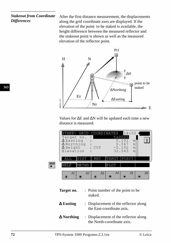
Stakeout from CoordinateDifferences
After the first distance measurement, the displacementsalong the grid coordinate axes are displayed. If theelevation of the point to be staked is available, theheight difference between the measured reflector andthe stakeout point is shown as well as the measuredelevation of the reflector point.
Target no. : Point number of the point to bestaked.
∆∆∆∆∆ Easting : Displacement of the reflector alongthe East-coordinate axis.
∆∆∆∆∆ Northing : Displacement of the reflector alongthe North-coordinate axis.
PR
OG
_Z
11
N0
E0
E
H N
Pt1
∆H
point to bestaked
∆Easting
∆Northing
STAKE\ GRID COORDINATES 14:03
ALL DIST REC TARGT POSIT
F1 F2 F3 F4 F5 F6
HELP METHD PLOT
MCTarget no. : Ta0025
∆ Easting : 0.101 m∆ Northing : 0.567 m∆ Height : CUT -0.102 mElevation : 32.543 m
Values for ∆E and ∆N will be updated each time a newdistance is measured.

© Leica TPS-System 1000 Programs-2.3.1en 73
IV
EL
AH
OH
BS
SM
SO
∆ ∆ ∆ ∆ ∆ Height : Difference in height between themeasured reflector point and thestakeout point. Positive in sign ifstakeout point is higher than thereflector position.
Elevation : Elevation of the measured reflectorpoint.
Simultaneously measure and record data on the activerecording device.
Measure a distance.
Record the measurement on the active recording device.
Enter target data as described in chapter "Measure &Record" of "System" - user manual.
Re-position the telescope on the target. Note, thisfunction is only available for motorized theodolites.
Change stakeout method. For more information refer tochapter "Select Stakeout Method".
Generate a plot of the stakeout data. For moreinformation refer to chapter "Plot".
Exit the program.
Acquire the next point to stake.

74 TPS-System 1000 Programs-2.3.1en © Leica
IV
EL
AH
OH
BS
SM
SO
Select Stakeout Method
Select the stakeout method in any stakeout dialog.
STAKE\ SELECT METHOD 14:03
POLAR ORTHO AUX GRID LIST
F1 F2 F3 F4 F5 F6
HELP
MCCoarse Meth : LINE OFFSET
Stakeout M. : POLAR STAKEOUT3D Stakeout. : ONPosition : 2DHght. Shift : 0.000 m
Coarse Meth :
Select the method for "COARSE POSITIONING":NONE no static method usedLINE OFFSET see chapter "Line Offset"ORTHOGONAL see chapter "Orthogonal"AZIMUTH & DISTAN see chapter "Azimuth and
Distance"Choosing NONE, the program will automaticallyproceed to the selected "STAKEOUT METHOD" andbypass the "COARSE POSITIONING" method afteryou selected a new stakeout point.
Stakeout M. :
Select the method for "STAKEOUT":POLAR STAKEOUT see chapter "Polar
Stakeout"ORTHOGONAL STAKE see chapter "Orthogonal
Stakeout"AUXILIARY POINTS see chapter "Stakeout with
auxiliary points"GRID COORDINATES see chapter "Stakeout from
Coordinate Differences"

© Leica TPS-System 1000 Programs-2.3.1en 75
IV
EL
AH
OH
BS
SM
SO
3D Stakeout : ON for 3D stakeout,OFF for 2D stakeout.
Position : Select positioning method. (Motorizedinstruments only):Off Automatic positioning off2D Positioning of the horizontal
drive3D Positioning vertical and
horizontal drive
Hght. Shift : All heights are changed by thisamount. The value can be changedonly when you are in this dialog.
Plot A plot is generated of the stakeout situation with a listof the numeric values, corresponding to the"STAKEOUT METHOD".
Note, below a typical plot is shown using the coordinate"STAKEOUT METHOD".
STAKE\ PLOT 14:03
F1 F2 F3 F4 F5 F6
HELP
MC
∆E PS
∆NR
∆E : 0.024 m∆N : 0.012 m

76 TPS-System 1000 Programs-2.3.1en © Leica
IV
EL
AH
OH
BS
SM
SO
Configuration
STAKE\ CONFIGURATION 14:03
INFO DFLT OFF
F1 F2 F3 F4 F5 F6
HELP
MC
Start the "Configuration Editor" from the "SEARCHPOINT " dialog.
3D Stake : ONLog File : OFFLog FlName : STAKEOUT.LOG
The "Configuration Editor" sets parameters for furtherprogram operations:
3D Stake : ON for 3-dimensional stakeout.Note the program will not perform 3Dstakeout if no elevation is availablefor the point to be staked.OFF for 2-dimensional stakeout.Note that there will be no difference inheight displayed.
Log File : OFF no recording in a Log fileSHORT reduce recording in a LogfileLONG detailed recording in a Logfile
Display software-version
Set the value to default. (3D stake = ON) .

© Leica TPS-System 1000 Programs-2.3.1en 77
IV
EL
AH
OH
BS
SM
SO
Exit the program.
Store the current configuration and proceed to thedialog "SEARCH POINT".
Log File If "Log File" is set to "ON" the measurements and theresults are stored in the ASCII-file specified within the"Configuration Editor". This file is created in thedirectory LOG on the memory card. Subsequently, youcan read the memory card on your PC and obtain a hardcopy of the Log-file.
Data will always be appended to the specified Log-file.
The Log-file contains the following information:
Header The header line will contain theprogram used, information about theinstrument, the name of the data file aswell as date and time.
Record SHORT recording of designcoordinates, setout height and heightdifference in the log file.
LONG recording of designcoordinates, setout coordinates unddifferences of coordinates in the logfile.

78 TPS-System 1000 Programs-2.3.1en © Leica
IV
EL
AH
OH
BS
SM
SO
Leica VIP Stakeout V 2.10Instrument : TCM1100, Serial 412160, (not named)User templ. : User 1Meas. file : FILE12.GSIProgram Start : 09/04/1996 at 01:18
Station no. : 3000E= 21.016m N= 64.666m ELV= 420.467m hi= 1.700m
Point no. : 1152, Hght. Shift = 0.000mDesign : E= 21.602m N= 62.184m ELV= 420.115mStaked : E= 21.606m N= 62.166m ELV= 420.355m hr= 1.500mDeltas : dO= -0.004m dN= 0.018m dELV= -0.240m
Typical log file entry in the "STAKEOUT" program

© Leica TPS-System 1000 Programs-2.3.1en 79
IV
EL
AH
OH
BS
SM
AS
FS
Free Station
Introduction This manual describes the "FREE STATION" programof the TPS SYSTEM 1000 theodolite series.
E
H
E0
PR
OG
_Z
19
N
Pt1 Pt2
Pt3
N0
This program can be used to deduce the three-dimensio-nal coordinates for the instrument station and thehorizontal orientation of the from measurements to amaximum of 10 target points.For simultaneous determination of the station elevation,height of instrument and height of reflector mustalready have been input and the elevation of the targetpoints must be known.
The program allows measurement in single or dual-facemode.Directions to target points can be determined, as canany combination of direction and distance. To computethe position coordinates, at least three elements (2directions and 1 distance) are necessary.

80 TPS-System 1000 Programs-2.3.1en © Leica
IV
EL
AH
OH
BS
SM
AS
FS
Station Data Enter station point number and height of the instrument.
FREST\ STATION DATA 14:03
αNUM
F1 F2 F3 F4 F5 F6
HELP CONF
MCStation no. : 1
Inst.Height : 1.555 m
Proceed to define the target points.
Start the "CONFIGURATION"
Alpha-numerical/numerical input.
Target Point Enter the target point number and height of thereflector.
FREST\ TARGET POINT 14:03
CALC LIST <-- --> αNUM
F1 F2 F3 F4 F5 F6
HELP
MCStation no. : 1
Refl.Height: 1.555 m
Run the calculation. Note, the key will beassigned after sufficient measurements were taken tocalculate a position.

© Leica TPS-System 1000 Programs-2.3.1en 81
IV
EL
AH
OH
BS
SM
AS
FS
Entry of target points into a list as well as selectingpoints for further use.
Displays the previous point from the list of points youentered. Note that this key will not be available untilthere is at least one point in the list.
Displays the next point in the list of points you entered.Note that this key will not be available until there is atleast one point in the list.
Retrieve the coordinates of the target point from theactive file. For further information, please refer todialog "IMPORT" described in the "SYSTEM" - usermanual.
Alpha-numerical/numerical input.
Point List Enter a maximum of 10 points. The same point can beretrieved several times.The same point number can be used several timeswithout new input.
Return to the dialog "Target Point".
FREST\ POINT LIST 14:03
Point 7 TAR07Point 8 TAR08Point 9 TAR09Point10 TAR10
MCPoint 1 TAR01
Point 2 TAR02Point 3 TAR03Point 4 TAR04Point 5 TAR05Point 6 TAR06
F1 F2 F3 F4 F5 F6
HELP

82 TPS-System 1000 Programs-2.3.1en © Leica
IV
EL
AH
OH
BS
SM
AS
FS
Measure Mode This dialog is similar to the TPS System 1000’s basic"MEASURE MODE" dialog. Once a measurement istaken, the program will return to the dialog "DEFINEPOINT" to acquire the next point for measuring.If the station coordinates can be calculated successfullyfrom the first few measurements, the ∆ Hz and ∆Vvalues are displayed for further entered target points.Motorized theodolites will automatically drive thetelescope to the target point.
Simultaneously measure and record data on the activerecording device. Return to the dialog "TARGETPOINT".
Measure a distance.
Record the measurement on the active recording device.Return to the dialog "TARGET POINT".
Enter target data. For further information, please referto chapter "Measure & Record" described in the"System" - user manual.
Change the theodolite face.
Call up the CODE function, as described in chapter"Measure & Record" described in the "System" - usermanual.
Exit the program.
Accept the measurement and return to the dialog"TARGET POINT".
FREST\MEASURRE MODE (GSI)14:03
ALL DIST REC TARGT
F1 F2 F3 F4 F5 F6
Point no. : 12Hz : 286°55'50"V : 91°16'20"Refl.Height : 1.500 mSlope Dist. : 22.039 m∆Hz : -----
HELP I<>II
MC

© Leica TPS-System 1000 Programs-2.3.1en 83
IV
EL
AH
OH
BS
SM
AS
FS
Calculation Calculates the 3D station coordinates and orientation aswell as the standard deviation of the results.
FREST\ RESULTS <L.SQRS> 14:03
SET STORE PLOT MORE
Orientation : 2°12'34"σEasting : 0.003 mσNorthing : 0.005 mσElevation : 0.005 mσOrient : 0°00'03"Calc Scale : YESScale : 0.999956
MCStation no. : 1
No. of Pts : 6Inst.Height : 1.635 mEasting : 2134.234 mNorthing : 4231.365 mElevation : 580.643 m
F1 F2 F3 F4 F5 F6
HELP ROBST
Station no : Point number assigned to the station
No. of Pts : Number of points measured
Inst.Height : Instrument Height
Easting : Calculated Easting for the station
Northing : Calculated Northing for the station
Elevation : Calculated Elevation for the station
Orientation : Oriented direction
σσσσσ Easting : Standard deviation of Easting
σσσσσ Northing : Standard deviation of Northing
σσσσσ Elevation : Standard deviation of the Elevation

84 TPS-System 1000 Programs-2.3.1en © Leica
IV
EL
AH
OH
BS
SM
AS
FS
σσσσσ Orient : Standard deviation of the Orientation
Calc Scale : YES scale factor is calculated,NO scale factor is not calculated
Scale : The scale factor of the free stationcalculation.Note that the scale is not shown ifset to NO.
Set orientation and station coordinates on theinstrument. Note that this key will end the program.
Record the following results on the active recordingdevice:
WI 11 Station Point NumberWI 25 Orientation correctionWI 84 Station EastingWI 85 Station NorthingWI 86 Station ElevationWI 87 Last reflector height usedWI 88 Instrument Height
Sketch of the station and the reference points used.
Show the results of individual measurements on thescreen (see dialog "More Information").
Measure more points. The program will recall the"TARGET POINT" dialog.
Select between the "Robust" method and the "Variati-on" method
Exit the program.

© Leica TPS-System 1000 Programs-2.3.1en 85
IV
EL
AH
OH
BS
SM
AS
FS
More Information Display the residuals of individual measurements. Youcan also disable points from the calculation of positionor height as well as delete erroneous measured points.
FREST\MEHR INFORMATIONEN14:03
RECLC <-- --> MEAS DEL NO
∆ Height : 0.020 mRefl.Height : 1.555 mEasting : 991.427 mNorthing : 1995.162 mElevation : 402.466 m
F1 F2 F3 F4 F5 F6
HELP
9/10 : Sequence number of the current pointand total number of points in themeasurement set. The scroll bar showsthe sequential position of themeasurements, graphically.
Use for Ht. : Use this measurement for heightdetermination (YES/NO)
Status : Use this measurement for calculation(ON/OFF).
Point no : The target point number.
Error Flag : Identified erroneous measurements.Possible values are:NONE measurement is OKHZ horizontal angle errorDIST distance errorHT height difference errorThe flags may also be combined, i.e.DIST + HZ
MC9/10
Use for Ht : YES Status: ONPoint no. : 12Error Flag : NONE∆ Hz : 0°00'03"∆ Distance : 0.050 m

86 TPS-System 1000 Programs-2.3.1en © Leica
IV
EL
AH
OH
BS
SM
AS
FS
∆∆∆∆∆ Hz. : Difference between calculated andmeasured Hz. angle
∆∆∆∆∆ Distance : Difference between calculated andmeasured distance
∆∆∆∆∆ Height : Difference between calculated andmeasured height
Refl. Ht. : Reflector height used for that targetpoint
Easting, Northing, Elevation : Target coordinatesused.
Recalculate the result.
Scroll to the measurements of the previous point.
Scroll to the measurements of the following point.
Measure more point. Return to dialog "TARGETPOINT".
Delete a point from the set of measurements . You cannow measure a new point in its place.
Exit the program.
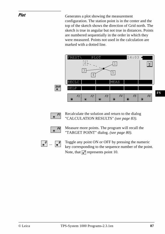
© Leica TPS-System 1000 Programs-2.3.1en 87
IV
EL
AH
OH
BS
SM
AS
FS
Plot Generates a plot showing the measurementconfiguration. The station point is in the center and thetop of the sketch shows the direction of Grid north. Thesketch is true in angular but not true in distances. Pointsare numbered sequentially in the order in which theywere measured. Points not used in the calculation aremarked with a dotted line.
FREST\ PLOT 14:03
RECLC MEAS
F1 F2 F3 F4 F5 F6
HELP
MC
Recalculate the solution and return to the dialog"CALCULATION RESULTS" (see page 83).
Measure more points. The program will recall the"TARGET POINT" dialog. (see page 80).
Toggle any point ON or OFF by pressing the numerickey corresponding to the sequence number of the point.Note, that represents point 10.
...
1
54
3
2

88 TPS-System 1000 Programs-2.3.1en © Leica
IV
EL
AH
OH
BS
SM
AS
FS
FREST\ CONFIGURATION 14:03
Log FlName : FREE_STA.LOG
MCHz Ori Acc : 0°00'32"
Ht Acc TP : 0.0250 mPosn Acc TP : 0.0250 mTwo Faces : NOUser Displ. : NOLog File : OFFINFO DFLT EDIT
F1 F2 F3 F4 F5 F6
HELP I<>II
The "Configuration Editor" sets parameters for furtherprogram operations:
Hz Ori Acc : Limit for the standard deviation of theorientation. The orientation isregarded as "error free", if thecomputed standard deviation of theorientation is within twice the enteredvalue.
Ht Acc TP : Height accuracy of the target points.The entered value, is used as an "apriori" accuracy in the calculation.The height is regarded as "error free",if the computed standard deviation iswithin twice the entered value.
Configuration
Configuration Editor
Start the "Configuration Editor" from the "STATIONDATA " dialog.

© Leica TPS-System 1000 Programs-2.3.1en 89
IV
EL
AH
OH
BS
SM
AS
FS
Posn Acc TP : Position accuracy of the target points.The entered value, is used as an "apriori" accuracy in the calculation.The position is regarded as "errorfree", if the computed standarddeviation is within twice the enteredvalue.
Two Faces : YES for dual-face measurement,NO for single-face.
User Disp : YES; the measured value indication isused from application "Measure andrecord".NO; the default indication is used forthe "Free Station".
Log File : ON, records measurements in a Log-File.The format is described on page90.
Log FlName : Enter the Log File Name
Display software-version
Set the values to default. Default values are shown inthe previous dialog.
Exit the program.
Store the current configuration and proceed to thedialog "STATION DATA".

90 TPS-System 1000 Programs-2.3.1en © Leica
IV
EL
AH
OH
BS
SM
AS
FS
Dual-face Measurement In the dual-face mode, the program will prompt formeasurements in both faces. When both measurementsare taken, the program will check the differencebetween the two. If the difference in angle is within 27'(0.5 gon) and the difference of two measured distancesis within 0.5 m (1.64 ft), the observations will beaveraged. These tolerances are used to avoid errors intarget identification. If exceeded an error message willbe displayed.
Data will always be appended to the specified Log-file.
The Log-file contains the following information:
Header The header line will contain theprogram used, information about theinstrument, the name of the data file aswell as date and time.
Record For each measurement, a record willbe stored containing :- Station coordinates and- orientation correction,- standard deviations for
Easting,Northing,Height of stationand orientation correction.
Log File If "Log File" is set to ON the measurements and theresults are stored in the ASCII-file specified within the"Configuration Editor". This file is created in thedirectory LOG on the memory card. Subsequently, youcan read the memory card on your PC and obtain a hardcopy of the Log-file.

© Leica TPS-System 1000 Programs-2.3.1en 91
IV
EL
AH
OH
BS
SM
AS
FS
The residuals for- horizontal angles,
- heights and
- measured distances
are also listed.
Leica VIP Free Station V 2.10Instrument : TCM1800, Serial 410000, (not named)User templ. : User 1Meas. file : FILE01.GSIProgram Start : 02/05/1996 at 11:23
Using Least-Squares Solution
Station no. : 200E= -3.5461m N= -0.7683m ELV= -0.6518m hi= 0.0000m
Ori.Corr. : 0°00'20"S.Dev. East : 0.0003mS.Dev. North : 0.0003mS.Dev. Elev. : 0.0015mS.Dev. Orient. : 0"00'02"
4 point(s) measured :
## Point no. d Hz d Height d Distance Error Flag1 109 0°01'21" 0.0012m -0.0000m NONE2 110 -0°00'00" -0.0045m -0.0002m NONE3 112 -0°00'25" 0.0018m 0.0010m NONE4 113 0°00'48" 0.0014m -0.0002m NONE
Continued next page

92 TPS-System 1000 Programs-2.3.1en © Leica
IV
EL
AH
OH
BS
SM
AS
FS
Using Robust Solution
Station no. : 200E= -3.5461m N= -0.7683m ELV= -0.6518m hi= 0.0000m
Ori.Corr. : 0°00'20"S.Dev. East : 0.0003mS.Dev. North : 0.0003mS.Dev. Elev. : 0.0015mS.Dev. Orient. : 0°00'02"
4 point(s) measured :
## Point no. d Hz d Height d Distance Error Flag1 109 0°01'21" 0.0012m -0.0000m NONE2 110 -0°00'00" -0.0045m -0.0002m NONE3 112 -0°00'25" 0.0018m 0.0010m NONE4 113 0°00'48" 0.0014m -0.0002m NONE
Typical log file entry in the "FREE STATION" program

© Leica TPS-System 1000 Programs-2.3.1en 93
IV
EL
AH
OH
BS
SM
AS
FS
RL
Reference Line
Introduction This manual describes the "REFERENCE LINE"program of the TPS SYSTEM 1000 theodolite series.The distance and the angle between two points iscalculated by the program.
"REFERENCE LINE" is a specialized form of stakeoutused for construction and building alignment. It permitspositioning of a point referred to a line. Points for use inthe program can be measured, entered manually, or readfrom the database.The program records individual measurements in thedatabase. In addition, the program generates a log filecontaining all data for a given measurement session.
H N Target pt
PR
OG
_Z
12
∆Offset
E
α
Pt1Pt2
Baseline
OffsetLine
∆LineRef.line

94 TPS-System 1000 Programs-2.3.1en © Leica
IV
EL
AH
OH
BS
SM
AS
FS
RL
The program also allows to determine various values ofheight determination as shown in the figure below.
FP Point of intersection of vertical withline P1-P2
NP Point of intersection with line P1- P2of perpendicular to P1- P2
∆∆∆∆∆H1 Height difference to start of line P1
∆∆∆∆∆H2 Height differencein relation to theinterpolated height FP of referenceline P1-P2.
∆∆∆∆∆Line Horizontal distance from P1 to FP(abscissa)
∆∆∆∆∆Spat.dist Spatial distance from P1 to NP
∆∆∆∆∆Perp.l Length of perpendicular from Targetpoint to Reference line
PR
OG
_Z
12
∆H1 ∆H2∆Offset
∆Line
P2
P1
FP
∆Spat.dist NP
Target point

© Leica TPS-System 1000 Programs-2.3.1en 95
IV
EL
AH
OH
BS
SM
AS
FS
RL
Baseline Points
Determine Base Points This dialog defines the two points of the baseline. Youcan either manually enter, measure or search for thepoint in the database.
REFLN\ REFERENCE LINE 14:03
INPUT MEAS SEARCαNUM
F1 F2 F3 F4 F5 F6
HELP CONF
MC1. POINT BASELINE
Rec. device : MEMORY-CARDSearch in : FILE01.GSI
Point/Code : 58
Manually enter the first base point. The TPS 1000manual input dialog will appear.
Proceed to determine the base point by a measurement.
Initiate a search of the point in the database.
Start the "Configuration Editor".
Exit the program.
or

96 TPS-System 1000 Programs-2.3.1en © Leica
IV
EL
AH
OH
BS
SM
AS
FS
RL
Measure a Base Point This dialog is used in accordance with the settings ofthe system function "Measure & Record" or accordingto the dialog shown below.
Simultaneously measure and record in the active file.Proceed with the dialog "1 POINT BASELINE" (page95). If the second point has already been measured, theprogram will proceed to the "DEFINE REF LINE"dialog.
Measure a distance.Record the measurement in the active file and proceedwith the dialog "1 POINT BASELINE" (page 95). Ifthe second point has already been measured, theprogram will proceed to the "DEFINE REF LINE"dialog.
Measure the distance. Accept the measurement withoutrecording. If the second point has already beenmeasured, the program will proceed with the "DEFINEREF LINE" dialog.
Enter the target data. For further information refer tochapter "Measure & Record" of "SYSTEM" - usermanual.
REFLN\ REFERENCE LINE 14:03
ALL DIST REC TARGT
F1 F2 F3 F4 F5 F6
Puoint no. : 12Hz : 286°55'50"V : 91°16'20"Refl.Height : 1.500 mSlope Dist. : 22.039 mHeight diff : 2.543 m
HELP I<>II
MC

© Leica TPS-System 1000 Programs-2.3.1en 97
IV
EL
AH
OH
BS
SM
AS
FS
RL
Change the theodolite face.
Call up the CODE function, as described in chapter"Measure & Record" of "SYSTEM" - user manual.
Exit the program.

98 TPS-System 1000 Programs-2.3.1en © Leica
IV
EL
AH
OH
BS
SM
AS
FS
RL
Define Reference Line The reference line can be defined by entering a distancevalue, a line offset value and an angle value for the baseline. Heights can be changed by a constant rate (eg, 1m)by entering a H offset value.
REFLN\ DEFINE REF LINE 14:03
NEWL MEAS
F1 F2 F3 F4 F5 F6
HELP
MC1.BasePoint : 12
2.BasePoint : 13Offset : 1.000 mLine : 1.558 mAlpha : 2°03'39"H Offset : 0.500 m
1.BasePoint : The first base point that defines thebase line.
2.BasePoint : The second base point that defines thebase line.
Offset : Establishes the displacement parallelto the base line.
Line : Establishes the distance from the firstreference point to the starting point ofthe new reference line.
Alpha : Establishes the angle between the baseline and the new reference line.
H Offset : Displaces the base line parallel inheight.
Define a new base line.
Accept parameters as displayed and proceed to the"RESULT REF LINE" dialog.
or

© Leica TPS-System 1000 Programs-2.3.1en 99
IV
EL
AH
OH
BS
SM
AS
FS
RL
Results Reference Line The "RESULTS REF LINE" dialog displays the data ofthe measured point refering to the reference line, asshown in dialog below:
Point No. : The point number of the stakeoutpoint.
∆∆∆∆∆ Offset : The delta value of line Offset inreference to the stakeout point.(ordinate)
∆∆∆∆∆ Line : The delta value of Line in referenceto the stakeout point. (abscissa)
∆ ∆ ∆ ∆ ∆ H : Height difference between thestakeout point as measured and theheight reference point.
∆∆∆∆∆Perp.lngth. : Length of perpendicular
∆∆∆∆∆Spat.dist. : Spatial distance
Elevation : Height of target point.
REFLN\RESLUTS REF LINE 14:03
ALL DIST REC TAGT
Point no. : 12∆ Offset : 0.020 m∆ Line : 1.468 m∆ H : -0.558 m∆Perp.lngth : 0.039 m∆Spat. dist : 3.020 m
MC
Elevation : 103.020 m
F1 F2 F3 F4 F5 F6
HELP
If " ∆Offset" is brought to "0" by turning the instrument,a distance measurement must always be carried out forcontrol purpose.

100 TPS-System 1000 Programs-2.3.1en © Leica
IV
EL
AH
OH
BS
SM
AS
FS
RL
Simultaneously execute distance measurement andrecord the measurement.
Measure a distance.
Record the measurement in the database.Depending on the setting in the "Configuration" dialoga measurement block containing delta values isrecorded:
WI 11 Point Number of targetWI 35 ∆OffsetWI 37 ∆HWI 39 ∆Line
or
WI 11 Point Number of targetWI 35 ∆OffsetWI 37 ∆PerpendicularWI 39 ∆Spatial distance
Depending on the setting in the "Configuration" dialoga record is written in the log file.When finished, the program will proceed the "DEFINEREF LINE" dialog.
Enter target data as described in the Measure & Recordof the System Manual.
Exit the program.
Proceed with dialog "DEFINE REF LINE".
Call up the CODE function, as described in chapter"Measure & Record" of "SYSTEM" - user manual.

© Leica TPS-System 1000 Programs-2.3.1en 101
IV
EL
AH
OH
BS
SM
AS
FS
RL
Configuration
Configuration Editor
Start the "Configuration Editor" from the "1. POINTBASELINE " dialog.
REFLN\ CONFIGURATION 14:03
INFO DFLT OFF
Offset : ONLine / α : OFFH.Offset. : OFFRec Diff : NONEUser Disp : NOHeight : Ref
MC
Log File : OFFLog FlName : REFLINE.LOG
F1 F2 F3 F4 F5 F6
HELP
The "Configuration Editor" lets you change and set thefollowing parameters that determine program operation:
Offset : Set to ON, the program will allow theinput of an offset from the referenceline.
Line / ααααα : Set to ON, the program will allow theinput of a distance from the first basepoint to the starting point of the newreference line, and also an anglebetween the base line and the newreference line .
H Offset : Set to ON, the program will allow theinput of a height offset.
S

102 TPS-System 1000 Programs-2.3.1en © Leica
IV
EL
AH
OH
BS
SM
AS
FS
RL
Rec Diff : Set to NONE, no additionalmeasurement is recorded.Set to O the program will record ∆Offset values only.Set to O/ L , the program will recordboth ∆ Offset and ∆ Line values.Set to O/L/H , the program will record∆ Offset, D Line and ∆Height of targetvalues.
If the option "Height" is set to"Inter " you can in addition calculatethe values:Set to O/S the program will recordboth ∆ Offset and ∆ Spatial distancevalues.Set to O/S/P, the program will record∆ Offset, ∆ Spatial distance and∆Perp.length of the perpendicular line.(Refer to figure page 94)
User Disp : Set to YES, the display defined in theMEAS application will be used.If set to NO, the "REFERENCELINE" default display applies.
Height : Set to Ref, ∆ Height (1) will becalculated from the first base pointand the reflector.Set to Inter , the program willcalculate ∆ Height (2) from theinterpolated height of the base line at∆ Line of the reflector position andthe reflector position itself.
If set to Inter , the Line / a option isset to NO automatically.
Log File : Set to ON, the program will recordmeasurement data in a log file in theformat described on page 103.
Log FlName : Enter the Log File Name.

© Leica TPS-System 1000 Programs-2.3.1en 103
IV
EL
AH
OH
BS
SM
AS
FS
RL
Log File If "Log File" is set to ON the measurements and theresults are stored in the ASCII-file specified within the"Configuration Editor". This file is created in thedirectory LOG on the memory card. Subsequently, youcan read the memory card on your PC and obtain a hardcopy of the Log-file.
Data will always be appended to the specified Log-file.
The Log-file contains the following information:
Header The header line will contain theprogram used, information about theinstrument, the name of the data file aswell as dateand time.
Configuration each modification of baseline andreference line is stored.
Record For each measurement, a record willbe stored containing: Point No., as-staked Easting, Northing, andElevation and their delta values.
Displays date and version of the running application.
Press to reset configuration parameters to their defaultvalues. Default settings are shown in the previousdialog.
Store the current configuration and proceed with dialog"1. POINT BASELINE".
Key to choose the different functions.

104 TPS-System 1000 Programs-2.3.1en © Leica
IV
EL
AH
OH
BS
SM
AS
FS
RL
Leica VIP Reference Line V 2.10Instrument : TCM1100, Serial 430000, Joe’s theodoliteUser Templ. : User 1Meas. File : FILE01.GSIProgram Start : 02/23/1995 at 13:00
Station no. : StationpointnumberE=1000.000m N=2000.000m H=400.000m hi=1.1150m
1.BasePoint : BaselinepointnumberE=1050.000m N=2050.000m H=410.000m
2.BasePoint : BaselinepointnumberE=1060.000m N=2060.000m H=420.000m
Offset. : 1.0000mLine : 2.6700mAlpha : 72°45'66"H Offset : 1.0000mHeight : REF
Point no. : 1025E=1055.000m N=2055.000m H=415.000m hr=1.1150m
Deltas : dP= 4.3403m: dL= 3.0907m: dH= -1.5027m
Typical log file entry in the "REFERENCE LINE" program

© Leica TPS-System 1000 Programs-2.3.1en 105
IV
EL
AH
OH
BS
SM
AS
FS
BL
RH
Remote Height
Introduction This manual describes the "Remote Height" program ofthe TPS System 1000 theodolite series. The distanceand the angle between two points is calculated by theprogram.
The elevation of a remote height point is calculatedfrom the zenith angle to the target and from themeasured distance to a reflector situated verticallybelow or above that target.To ensure correct results, the target and the reflectormust be lined up vertically. In practice it is not generallypossible to maintain an exactly-vertical line, and so youmust decide what lateral deviation can be tolerated. Thehorizontal distance to the inaccessible target musthowever coincide with the horizontal distance to thereflector.When the instrument is aligned and the stationcoordinates have been set, the position coordinates ofthe remote height can be calculated and stored in thedata file.
EPR
OG
_Z
13
∆H
E0
H N
N0
∆V

106 TPS-System 1000 Programs-2.3.1en © Leica
IV
EL
AH
OH
BS
SM
AS
FS
BL
RH
Measure Base Point This dialog is used in accordance with the settings ofthe system function "Measure & Record" or accordingto the dialog shown below.
REMHT\ MEASURE BASE PT 14:03
ALL DIST REC TARGT REMOTαNUM
F1 F2 F3 F4 F5 F6
Point no. : Station12Hz : 16°55'50"V : 91°16'20"Refl.Height : 1.664 mSlope Dist. : ----- mHeight diff : -----
HELP CONF I<>II
Point No. : The point number of the base point.
Hz : Horizontal direction from the remotepoint to the base point.
V : Vertical angle to the remote point.
Refl.Height : Reflector height used for the targetpoint.
Slope dist. : Slope distance from the instrumentstation to the base point.
Height diff : Height difference between the basepoint ground and the instrumentground.
Simultaneously measure and record in the active file.Proceed with the "REMOTE POINT" dialog.
Measure a distance. Record the measurement in theactive file and proceed with the "REMOTE POINT"dialog.
Measure the distance. Accept the measurement withoutrecording. Proceed with the "REMOTE POINT" dialog.
MC

© Leica TPS-System 1000 Programs-2.3.1en 107
IV
EL
AH
OH
BS
SM
AS
FS
BL
RH
Enter the target data. . For further information refer tochapter "Measure & Record" of the "SYSTEM" - usermanual.
Proceed with "REMOTE POINT" dialog.
Start the "Configuration Editor".
Change the theodolite face.
Call up the CODE function, as described in chapter"Measure & Record" of the "SYSTEM" - user manual.
Exit the program.
Alpha-numerical/numerical input.

108 TPS-System 1000 Programs-2.3.1en © Leica
IV
EL
AH
OH
BS
SM
AS
FS
BL
RH
Measure Remote Point Once the base point has been measured, this dialogshows the position of the point - above or below thebase point - aimed with the telescope. The data areimmediately updated while turning the instrument.
REMHT\ MEASURRE REMOTE PT14:03
Northing : 124.003 mElevation : 768.005 m
MCPoint no. : Station12
Hz : 16°55'50"V : 91°16'20"Slope Dist. : 23.345 m∆Hgt diff : 6.435 mEasting : 3453.998 m
STORE TARGT BASE
F1 F2 F3 F4 F5 F6
HELP I<>II
Point No. : The point number of the remote point.
Hz : Horizontal direction from theinstrument to the remote point.
V : Vertical angle to the remote point.
Slope dist. : Slope distance from the instrumentstation to the remote point.(calculated)
∆∆∆∆∆ Hgt diff : Height difference between the remotepoint and the base point ground.
Easting : Calculated Easting (Y) for the remotepoint.
Northing : Calculated Northing (X) for theremote point.
Elevation : Calculated Elevation for the remotepoint.

© Leica TPS-System 1000 Programs-2.3.1en 109
IV
EL
AH
OH
BS
SM
AS
FS
BL
RH
Record the measurement in the database.
Enter the target data. . For further information refer tochapter "Measure & Record" of the "SYSTEM" - usermanual.
Return to the "MEASURE BASE POINT" dialog.
Call up the CODE function, as described in chapter"Measure & Record" of the "SYSTEM" - user manual.
Return to the "MEASURE BASE POINT" dialog.
Exit the program.

110 TPS-System 1000 Programs-2.3.1en © Leica
IV
EL
AH
OH
BS
SM
AS
FS
BL
RH
Start the "Configuration Editor" from the "MEASUREREMOTE POINT" dialog.
REMHT\ CONFIGURATION 14:03
INFO DFLT YES
F1 F2 F3 F4 F5 F6
HELP
MCUser Displ : NO
Hor.Pos.Tol : 0.200 mRec ∆H WI37 : OFF
The "Configuration Editor" sets parameters for furtherprogram operations:
User Disp : Set to YES, the display defined in the"MEAS" application will be used.If set to NO, the "REMOTEHEIGHT" default display applies.
Hor.Pos.Tol : Horizontal distance tolerance thatvalid point measurements cannotexceed.
Rec ∆∆∆∆∆H WI37 :Set to ON, the program will store ∆height difference as record WI37 inthe database.
Configuration
Displays date and version of the running application.
Reset configuration parameters to their default values.Default settings are shown in dialog above.
Accept the current configuration and proceed to thedialog "MEASURE BASE PT".

© Leica TPS-System 1000 Programs-2.3.1en 111
IV
EL
AH
OH
BS
SM
AS
FS
BL
HB
HP
Hidden Point
Introduction This manual describes the "HIDDEN POINT" programof the TPS SYSTEM 1000 instruments.
The program allows measurements to a point that is notdirectly visible using a special hidden-point rod. Thedata for the hidden point are calculated frommeasurements to the prisms mounted on the pole with aknown spacing and a known length of pole. The polestill may be kept slope."Measurements" are calculated as if the hidden pointwas observed directly. These "calculatedmeasurements" can also be recorded.
The hidden-point rod can have either two or threereflectors. The rod you are using is defined in the"CONFIGURATION" of the program. Here, you enterthe length of the rod, spacing between reflectors, andthe prism constant. Refer to Figure on page 112, whichillustrates a hidden-point rod with three reflectors.
If the hidden-point rod you are using has threereflectors, the program calculates coordinates for thehidden point from three combinations:
Reflector 1 + Reflector 2Reflector 3 + Reflector 2Reflector 1 + Reflector 3
In the case of motorized theodolites, you can configurethe program in such a way, that it points the telescope atthe third reflector automatically after the first tworeflectors have been measured.

112 TPS-System 1000 Programs-2.3.1en © Leica
IV
EL
AH
OH
BS
SM
AS
FS
BL
HB
HP
EPR
OG
_Z
14
H N
N0
E0
R1-R2
R1-R3
Start the "Configuration Editor" from the "MEASURE"dialog.
HDNPT\ CONFIGURATION 14:03
INFO DFLT YES
MCUser Displ : NO
Meas. Tol. : 0.020 mAdd. const. : 0.000 mNo. of Refl : 3Auto Pos. : ONRod Length : 5.000 m
F1 F2 F3 F4 F5 F6
HELP
Space R1-R2 : 1.000 mSpace R1-R3 : 0.500 m
The "Configuration" let you set the followingparameters that determine program operation and definethe hidden-point rod you are using:
User Displ : YES use the display defined in"MEASURE & RECORD".Set NO use the default display of theprogram "HIDDEN POINT".
Totallength ofrod
Configuration

© Leica TPS-System 1000 Programs-2.3.1en 113
IV
EL
AH
OH
BS
SM
AS
FS
BL
HB
HP
Meas. Tol : Limit for the difference between thegiven and measured spacing of thereflectors. If the tolerance value isexceeded, the program will issue awarning.In case of measurements with 3 prismthe values are also used as limit forthe max. deviation of the 3measurements.
Add. const. : Input of prism constant for the prismsof the pole. The prism constant set inthe system is disregarded.
No. of Refl. : Number of the reflectors on the rodyou are using. Move the input cursorto this line, then toggle to either 2 or 3.
Auto pos. : On the program will automaticallypoint the telescope of a motorizedtheodolite at the third reflector oncethe first two reflectors have beenmeasured. The exact pointing must bemade manually.
Rod Length : Total length of hidden-point rod.
Space R1-R2 : Spacing between the centers ofreflector R1 and reflector R2.
Space R1-R3 : Spacing between the centers ofreflector R1 and reflector R3. Enteronly for rods with three reflectors.Reflector 3 must be situated betweenreflector 1 and 2.
Displays date and version of the running application.
Set values to default. Default values are displayed onpage 112.
Accept the current configuration and proceed to"MEASURE ROD"Note that all parameters for the rod you are using mustbe defined before you can proceed. If any of theparameters have not been defined, the program willissue an error message to this effect. Press OK to clearthe message, then make any necessary settings in the"CONFIGURATION".

114 TPS-System 1000 Programs-2.3.1en © Leica
IV
EL
AH
OH
BS
SM
AS
FS
BL
HB
HP
Measure Rod The program will display the TPS 1000 "Measure &Record"dialog or the dialog shown below.If the difference of the given and measured spacingbetween the reflectors exceeds the "Meas. Tol. limit" amessage is displayed.You may accept the measurement or re-measure thereflector.
HDNPT\ MEASURE PRISM 1 14:03
MCPoint no. : Station12
Hz : 16°55'50"V : 91°16'20"Slope Dist. : ----- mHeight diff : ----- m
ALL DIST REC TARGT
F1 F2 F3 F4 F5 F6
HELP CONF I<>II
Simultaneously measure and record in the active file.Proceed with the same dialog for the next reflector. Ifthe last point has already been measured, the programwill proceed to the "RESULT" dialog.
Measure a distance. Record the measurement in theactive file and proceed with the same dialog for the nextreflector. If the last point has already been measured,the program will proceed to the "RESULT" dialog.
Measure the distance. Accept the measurement withoutrecording. Proceed with the same dialog for the nextreflector. If the last point has already been measured,the program will proceed to the "RESULT" dialog.
The prism constant used in the program is shown in thedistance measurement display during the distancemeasurement. The prism name also shown in thisdisplay has nothing to do with the prism constant andcan be ignored.

© Leica TPS-System 1000 Programs-2.3.1en 115
IV
EL
AH
OH
BS
SM
AS
FS
BL
HB
HP
Enter the target data. For further information refer tochapter "Measure & Record" of "SYSTEM" - usermanual.
Choosing another reflector and therefore another prismconstant via this function is NOT recommendedbecause the actually selected prism constant is onlyused for the current measurement. After confirming/
storing a measurement with / "REC" or "ALL" theprism constant set in the program configuration isautomatically used again. This could result in errors.Therefore always set the prism constant of the pole inthe configuration of the program. Refer to pages 112and 113.
Change the theodolite face.
Call up the CODE function, input of a code block.
Point no. : The Point number.
Hz : Horizontal direction to the hiddenpoint.
Results Once all reflectors have been measured, the programwill display the results of the hidden-point calculation.If 3 reflectors are used, the hidden point positionobtained from the median value of the 3 combinations isdisplayed.
HDNPT\ RESULTS 14:03
Northing : 12145.281 mElevation : 306.005 m
MCPoint no. : Station12
Hz : 16°55'50"V : 91°16'20"Slope Dist. : 3.345 mHeight diff : -0.435 mEasting : 2253.635 m NEW REC TARGT
F1 F2 F3 F4 F5 F6
HELP

116 TPS-System 1000 Programs-2.3.1en © Leica
IV
EL
AH
OH
BS
SM
AS
FS
BL
HB
HP
V : Vertical angle to the hidden point.
Slope. Dist. : Slope distance to the hidden point.
Height Diff : Height difference from instrumentstation to the hidden point.
Easting : Calculated Easting (E) for the hiddenpoint.
Northing : Calculated Northing (N) for thehidden point.
Elevation : Calculated Elevation for the hiddenpoint.
Take a new hidden-point measurement.
Store the point calculation on the recording device.
If the prism constant is also stored (depending on theREC mask) during storing of the calculated data of thehidden point this value can be ignored because it is notrelevant for the calculation.
Enter target data as described in chapter "Measure &Record" of "SYSTEM" - user manual.
Call up the CODE function, as described in chapter"Measure & Record" of "SYSTEM" - user manual.
Proceed to measure a new hidden point.
Exit the program.

© Leica TPS-System 1000 Programs-2.3.1en 117
IV
EL
AH
OH
BS
SM
AS
FS
BL
HB
KM
AR
Area (Computation of Area)
Introduction This manual describes the "AREA" program of the TPSSYSTEM 1000 theodolite series.
PR
OG
_Z
15
H N
E
Pt1 Pt2
Pt3
Pt4PT5
Pt6
An area can be defined by a series of straight lines andarcs. Arcs are defined by 3 radial points or 2 radialpoints and radius.

118 TPS-System 1000 Programs-2.3.1en © Leica
IV
EL
AH
OH
BS
SM
AS
FS
BL
HB
KM
AR
Measure Mode
Straight line AREA\ MEASURE POINT 14:03
Height diff : ----- mEasting : ----- mNorthing : ----- mElevation : 206.7963 mAzimuth : 182°25'05"Seg. Len. : 0.203 m
MC
ALL DIST REC TARGT IMPOR
Segs Meas. : 0Point no. : 1Refl.Height : 0.000 mHz : 95°55'50"V : 91°16'20"Slope Dist. : ----- m
F1 F2 F3 F4 F5 F6
HELP CONF DEL CALC ARC NEW
Segs Meas. : Counts the number of segments. Witha new area the segment counter will beset to zero.
Seg. Len. : Length of the last straight linesegment measured.
Simultaneously measure and record data on the activerecording device. Return to dialog "MEASUREPOINT"
Measure a distance and record data on the activerecording device.
Measure a distance without recording.
Enter the target data. For further information refer tochapter "Measure & Record" of "SYSTEM" - usermanual.
Import target coordinates. For further information,please refer to chapter "Setup" of "SYSTEM" - usermanual.

© Leica TPS-System 1000 Programs-2.3.1en 119
IV
EL
AH
OH
BS
SM
AS
FS
BL
HB
KM
AR
Start the "Configuration editor".
Deletes last completed segment. Resume at the start of anew segment.
Close the area polygon to the start point and calculatesarea and length of perimeter. The display of the resultsis shown in chapter "CALCULATION".
Select arc as the next segment.
Resets the segment counter to zero. Results of the lastarea computation will be erased.
Call up the CODE function.

120 TPS-System 1000 Programs-2.3.1en © Leica
IV
EL
AH
OH
BS
SM
AS
FS
BL
HB
KM
AR
Arcs During measurement, you can choose the ARC functionto measure an arc defined by 3 radial points or 2 pointsand radius.Select the correct options before proceeding with thefirst point of the segment.
Ensure the central angle of any arc is always smallerthan 180° (200 gon).
• Three Points
Determine the three points of an arc sequentially.Completing the third point the program continues withDialog "Measure point" (page 118).
AREA\ 3 POINT ARC 14:03
Height diff : ----- mEasting : ----- mNorthing : ----- mElevation : ----- m
MC
ALL DIST REC TARGT IMPOR
3 point ARC, starting point:Point no. : 1Refl.Height : 0.000 mHz : 95°55'50"V : 91°16'20"Slope Dist. : ----- m
F1 F2 F3 F4 F5 F6
HELP RAD
Simultaneously measure and record data on the activerecording device.
Measure a distance and record data on the activerecording device.
Measure a distance without recording.

© Leica TPS-System 1000 Programs-2.3.1en 121
IV
EL
AH
OH
BS
SM
AS
FS
BL
HB
KM
AR
Enter the target data. For further information refer tochapter "Measure & Record" of "SYSTEM" - usermanual.
Import target coordinates. For further information,please refer to chapter "Setup" of "SYSTEM" - usermanual.
Select arc defined by 2 points and radius.
Call up the CODE function, as described in chapter"Measure & Record" of "SYSTEM" - user manual.
Exit the program.
• Radius Arc
Determine the two points of an arc sequentially. Afterthe second point the "Measure point" dialog (page 118)prompts to input the radius.
AREA\ RADIUS ARC 14:03
Height diff : ----- mEasting : ----- mNorthing : ----- mElevation : ----- m
MC
ALL DIST REC TARGT IMPOR
Radius ARC, starting point:Point no. : 1Refl.Height : 0.000 mHz : 95°55'50"V : 91°16'20"Slope Dist. : ----- m
F1 F2 F3 F4 F5 F6
HELP 3 PT

122 TPS-System 1000 Programs-2.3.1en © Leica
IV
EL
AH
OH
BS
SM
AS
FS
BL
HB
KM
AR
Simultaneously measure and record data on the activerecording device.
Measure a distance and record data on the activerecording device.
Measure a distance without recording.
Enter the target data. For further information refer tochapter "Measure & Record" of "SYSTEM" - usermanual.
Import target coordinates. For further information,please refer to chapter "Setup" of "SYSTEM" - usermanual.
Press 3 Pt. to switch to the 3-Point Arc method .
Call up the CODE function, as described in chapter"Measure & Record" of "SYSTEM" - user manual.
Exit the program.
AREA\ 2 PUNKTE & RADIUS 14:03
MC
F1 F2 F3 F4 F5 F6
HELP
Start Pt. : 12End Pt. : 70Radius : ----- m
For arcs to the left enter the radius negative and forarcs to the right enter the radius positive.
Accept the input. Continue with dialog "MEASUREPOINT" (page118).

© Leica TPS-System 1000 Programs-2.3.1en 123
IV
EL
AH
OH
BS
SM
AS
FS
BL
HB
KM
AR
Calculation Displays number of segments, computed area andlength of perimeter.
AREA\ RESULTS 14:03
MCNo. Segs. : 10
Area : 892.888 m²Hectares : 0.089Perimeter : 295.563 m
NEW STORE PLOT
F1 F2 F3 F4 F5 F6
HELP
No. Segs. : Number of segments used.
Area : Computed area in units of measure.
Hectares/ : Computed area in hectares or acres1 .Acres 1 acre = 43560 ft².
Perimeter : Length of perimeter of the current unitof measure.
1 depending on the setting of the distance unit metre orfeet.
Start a new area. Resets the segment counter to zero.Results of the last area computation will be erased.
The following format will be used to record calculatedarea results:
WI 41: Code block identification( default = 36 )
WI 42: Number of segments used.WI 43: Area in the current measurement units,
always with one decimal place.WI 44: Length of perimeter in the current units ofmeasure with one decimal place.

124 TPS-System 1000 Programs-2.3.1en © Leica
IV
EL
AH
OH
BS
SM
AS
FS
BL
HB
KM
AR
Area results recording format
Code( default = 36 )
no. of segments area polygon length polygonperimeter
=4 4500.3 m2 392.2 m
41001+00000036 42...+00000004 43...+00045003 44...+00003922
WI 41 WI 42 WI 43 WI 44
Generate a plot of the area.
Continue with dialog "MEASURE POINT".
Exit the program.
Shows a plot of the present area.
Plot
AREA\ PLOT 14:03
F1 F2 F3 F4 F5 F6
HELP
RESLT
Return to the dialog "RESULTS".
Umfang
Perimeter

© Leica TPS-System 1000 Programs-2.3.1en 125
IV
EL
AH
OH
BS
SM
AS
FS
BL
HB
KM
AR
Configuration
Configuration Editor
Start the "Configuration Editor" from the "MEASUREPOINT" dialog.
AREA\ CONFIGURATION 14:03
INFO DFLT YES
MCTwo Faces : NO
Code : 36Log File : OFFLog FlName : AREA.LOG
F1 F2 F3 F4 F5 F6
HELP
The "Configuration Editor" sets parameters for furtherprogram operations:
Two Faces : Set YES for dual-face measurement,NO for single-face.
Code : Enter the block identification code forrecording the area results ( max. eightalpha numeric characters )
Log File : Set to ON, the program will recordmeasurement data in a log file in theformat described on page 128.
Log FlName : Enter the Log File Name.
Display date and version of the running application
Set the values to default. Default values are displayed indialog above.

126 TPS-System 1000 Programs-2.3.1en © Leica
IV
EL
AH
OH
BS
SM
AS
FS
BL
HB
KM
AR
Store the current configuration and proceed to thedialog "MEASURE POINT". Points can be added tothe current area or a new area can be started.
Exit the program.
Dual-face Measurement In the dual-face mode, the program will prompt formeasurements in both faces. When both measurementsare taken, the program will check the differencebetween the two. If the difference in angle is within 27'(0.5 gon) and the difference of two measured distancesis within 0.5 m (1.64 ft), the observations will beaveraged. These tolerances are used to avoid errors intarget identification. If exceeded an error message willbe displayed.
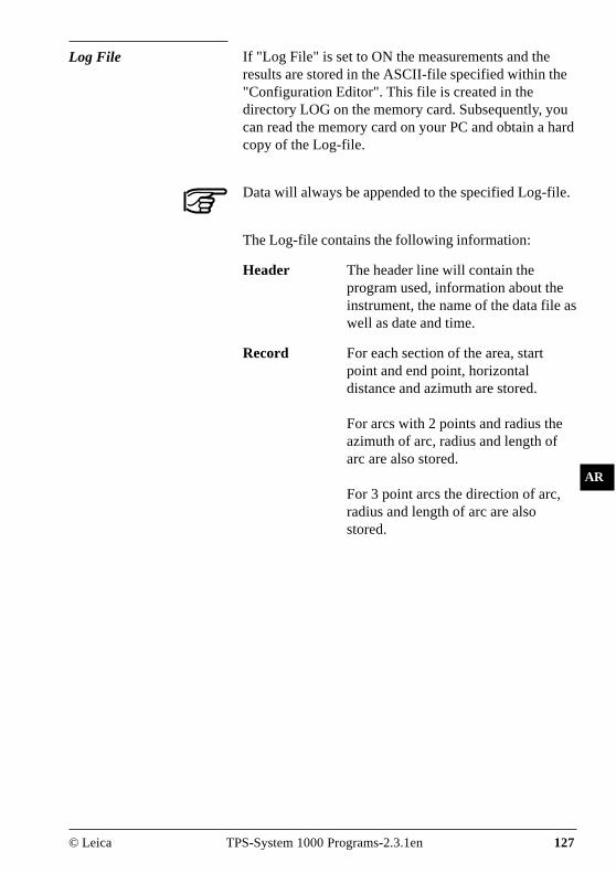
© Leica TPS-System 1000 Programs-2.3.1en 127
IV
EL
AH
OH
BS
SM
AS
FS
BL
HB
KM
AR
Log File If "Log File" is set to ON the measurements and theresults are stored in the ASCII-file specified within the"Configuration Editor". This file is created in thedirectory LOG on the memory card. Subsequently, youcan read the memory card on your PC and obtain a hardcopy of the Log-file.
Data will always be appended to the specified Log-file.
The Log-file contains the following information:
Header The header line will contain theprogram used, information about theinstrument, the name of the data file aswell as date and time.
Record For each section of the area, startpoint and end point, horizontaldistance and azimuth are stored.
For arcs with 2 points and radius theazimuth of arc, radius and length ofarc are also stored.
For 3 point arcs the direction of arc,radius and length of arc are alsostored.

128 TPS-System 1000 Programs-2.3.1en © Leica
IV
EL
AH
OH
BS
SM
AS
FS
BL
HB
KM
AR
Leica VIP Area V 2.10Instrument : TCM1100, Serial 430000, Joe’s theodoliteUser templ. : User 1Meas. file : FILE01.GSIProgram Start : 02/23/1995 at 13:00
Segment Number : 1Start Point : 1End Point : 2H Distance : 5.5555mAzimuth : 140°11'17"
Segment Number : 2Start Point : 2End Point : 4Curve RightRadius : 4.9089mARC Length : 2.326m
Segment Number : 3Start Point : 4Second Point : 5End Point : 6Curve RightRadius : 5.362mARC Length : 2.254m
Number of Segments : 3Area : 9.8496m2Hectares : 0.0010Perimeter : 13.8396m
Typical log file entry in the "AREA" program

© Leica TPS-System 1000 Programs-2.3.1en 129
IV
EL
AH
OH
BS
SM
AS
FS
BL
HB
KM
FB
SA
Sets of Angles
Introduction This manual describes the "Sets of Angles" program ofthe TPS SYSTEM 1000 theodolite series.
PR
OG
_Z
16
E
The program permits direction measurements to targetsof which coordinates are not necessarily known. Theaverage direction of all sets, the standard deviation forone observed direction and the standard deviation forthe average of all directions is computed for each target.To calculate a result, a minimum of two full sets mustbe observed. Measurements in two faces must exist foreach target .Once the program has "learned" the targets and theirrespective sequence during the first set in face I, theobserver is guided throughout the following measuringsequence.A maximum of 250 measurements per instrumentstation (in 2 faces) can be handled in one calculation.
Pt3 Pt2
Pt1H N
Set2 (0°00'00")
Set1(0°00'00")

130 TPS-System 1000 Programs-2.3.1en © Leica
IV
EL
AH
OH
BS
SM
AS
FS
BL
HB
KM
FB
SA
Sets Menu
Sets menu - view The point numbers and sequence of the targets arestored in the program during the observation of the firsthalf set in face I. This is designated as the "LearningPhase". The observer is thereafter guided throughoutthe observation sequence, i.e. the targets are proposedas per "learned" sequence using the selectedobservation method. To locate the targets easily, thehorizontal and vertical differences in direction aredisplayed. Turning these differences to "zero", therelevant target is visible. Motorized theodolites willautomatically drive the telescope to the specified targetpoint, if the first half set was measured successfully.Complete directions must be observed for all targetswithin the first set. A complete direction is defined as adirection observed in both faces.During observation the program tests, if the correct faceis used. As soon as the last "learned" target has beenobserved, the program changes automatically to face II.
F1 F2 F3 F4 F5 F6
HELP CONF
SETS\ SETS MENU 14:03
MC
Start the "CONFIGURATION".
Measure First Set 0Measure Further Set 1Calculate Horizontal Sets 2Calculate Vertical Sets 3End Program 4

© Leica TPS-System 1000 Programs-2.3.1en 131
IV
EL
AH
OH
BS
SM
AS
FS
BL
HB
KM
FB
SA
Measure Mode
Entry of target points into a list as well as selectingpoints for multiple use.
Displays the previous point from the list of points youentered. Note that this key will not be available untilthere is at least one point in the list.
Displays the next point in the list of points you entered.Note that this key will not be available until there isat least one point in the list.
Ends the 1. half set and returns to the dialog "SETSMENU".
• Measure First Set
This option starts the first set and the "Learning Phase"of a new instrument station. The point number for thetargets must be entered in Dialog "FIRST SET".
F1 F2 F3 F4 F5 F6
HELP
SETS\ FIRST SET 14:03
MCSet no. : 1
Seg. no. : 1Face : IPoint no. : 501Refl.Height : 1.300 mAuto Meas. : YES
LIST <-- --> DONE αNUM
Set no. : Displays the active set.
Seq. no. : Displays the sequence number of theselected target out of the total numberof target used.
Face : Displays the face.
Point no. : Target point number.
Refl.Height : Reflector height of target point.
Auto Meas. : Automatic measurement ON/OFF

132 TPS-System 1000 Programs-2.3.1en © Leica
IV
EL
AH
OH
BS
SM
AS
FS
BL
HB
KM
FB
SA
Select alpha-numeric/numeric input.
Exit the program.
Proceed to the "MEASURE" dialog (displayed below).
F1 F2 F3 F4 F5 F6
HELP I<>II
SETS\ FIRST SET 14:03
MC
ALL DIST REC TARGT EDIT
Point no. : 501Refl.Height : 1.300 mHz : 249°10'20"V : 90°19'52"∆HZ : -----∆V : -----
∆∆∆∆∆Hz / ∆∆∆∆∆V : Are not activ during the first set. Thedifferences are shown for all further setsrelative to the measurements of the firsthalf set.
This "MEASURE" dialog is shown during themeasurement to targets. The program return to thedialog "FIRST SET" (page 131) on completion of ameasurement or to the "FURTHER SET" dialog (page133).
Simultaneously measure and record data on the activerecording device. Return to the dialog "FIRST SET".
Measure and record a distance.1
Measure without recording the measurement on theactive recording device.
Enter the target data. For further information refer tochapter "Measure & Record" of the "SYSTEM" - usermanual.
Change the theodolite face.
Proceed to "FIRST SET".
1 Distance measurement is optional.

© Leica TPS-System 1000 Programs-2.3.1en 133
IV
EL
AH
OH
BS
SM
AS
FS
BL
HB
KM
FB
SA
• Measure Further Set
To measure the sets, the user is guided the measurementsequences. The following dialog selects points usedwithin the 1. half set. The measurement sequencerequires no special target selection due to the pre-defined configuration.
F1 F2 F3 F4 F5 F6
HELP DONE
SETS\ MEASURE SET 14:03
MCSet no. : 1
Seg. no. : 1Face : IPoint no. : 501Refl.Height : 1.300 mAuto Meas. : YES
<-- --> POSIT
Set no. : Displays the active set.
Seg. no : Internal ordinal number from 1st halfset.
Face : Displays the face.
Selects the previous point from a list of points.
Selects the next point from a list of points.
Turn the telescope to the selected point.
Returns to the "Sets Menu"

134 TPS-System 1000 Programs-2.3.1en © Leica
IV
EL
AH
OH
BS
SM
AS
FS
BL
HB
KM
FB
SA
To detect the targets easily, the horizontal and verticalangle differences are shown in a special display. If theseare "turned to zero", the selected target is visible withinthe field of view.Motorized instruments sight the target automaticallyafter the successful measurements of the first half set.
F1 F2 F3 F4 F5 F6
HELP
TELESCOPE POSITIONING 14:03
MCHz- and V-positioning:
Set direction(s) to zero.
∆HZ : -3°56'23"∆V : 1°22'25"
ABORT OK
∆∆∆∆∆Hz : Difference in horizontal direction.∆∆∆∆∆V : Difference in vertical direction
Ends the telescope positioning.
Ends the telescope positioning. Are activated if thepresent telescope position is within 27' (0.5 gon) of theexpected position. This is confirmed accustically.
Further measurements follow the same rules asdescribed in chapter "Measure first set".
or

© Leica TPS-System 1000 Programs-2.3.1en 135
IV
EL
AH
OH
BS
SM
AS
FS
BL
HB
KM
FB
SA
Calculate Mode • Calculate Horizontal and Vertical Sets
The display-format is the same for horizontal andvertical directions. The data displayed, refer to theselected calculation.Standard deviations of a single direction in both faces(mR) and the standard deviation for an averageddirection from all sets (mM) are calculated.
Computations of standard deviations require, that alltargets and sets are observed in two faces. Exceptionsmay exist, in which case the standard deviation shouldbe seen as an approximation to be used as a fieldcontrol. The correct standard deviations a posteriori canbe calculated using the recorded data and a suitablecomputation method.
F1 F2 F3 F4 F5 F6
HELP
SETS\ HZ SET RESULTS 14:03
MCPts. Active : 4
Set Active : 2mR : 0°00'24"mM : 0°00'17"
STORE MORE
Pts. Active : Number of observed points used in thecalculation.
Sets Active : Number of observed sets used in thecalculation.
mR : Standard deviation of one observedhorizontal or vertical direction.
mM : Standard deviation of an averagedirection from all sets.

136 TPS-System 1000 Programs-2.3.1en © Leica
IV
EL
AH
OH
BS
SM
AS
FS
BL
HB
KM
FB
SA
Results of sets of angles are recorded in the activ filefor measurements. (For details see dialog "FORMATSAND MORE INFORMATION" )
Show the results of individual measurements on thescreen. ( For details see dialog "MORE INFORMATI-ON")
Exit the program
• Formats and Data Recording
The following format is used to record results in theactiv file for measurements.
Number of measurements and accuracies.WI 41 Code "HZ-RESLT" or "V0-RESLT"WI 42 Number of targets.WI 43 Number of observed sets.WI 44 Standard deviation of a horizontal or
vertical direction.WI 45 Standard deviation of a horizontal or a
vertical direction averaged from all sets.HZ-RESLT: (Number of observations and accuracies)
Code Number oftargets
Number ofsets
mR mM
=4 =3 = 52" = 37"
410039+HZ-RESLT42....+0000000443....+0000000344....+0000052045....+00000370
WI 41 WI 42 WI 43 WI 44 WI 45
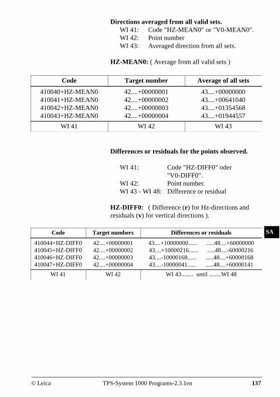
© Leica TPS-System 1000 Programs-2.3.1en 137
IV
EL
AH
OH
BS
SM
AS
FS
BL
HB
KM
FB
SA
Directions averaged from all valid sets.WI 41: Code "HZ-MEAN0" or "V0-MEAN0".WI 42: Point numberWI 43: Averaged direction from all sets.
HZ-MEAN0: ( Average from all valid sets )
Code Target number Average of all sets
410040+HZ-MEAN0410041+HZ-MEAN0410042+HZ-MEAN0410043+HZ-MEAN0
42....+0000000142....+0000000242....+0000000342....+00000004
43....+0000000043....+0064104043....+0135456843....+01944557
WI 41 WI 42 WI 43
Code Target numbers Differences or residuals
410044+HZ-DIFF0410045+HZ-DIFF0410046+HZ-DIFF0410047+HZ-DIFF0
42....+0000000142....+0000000242....+0000000342....+00000004
43....+10000000...... .....48....+6000000043....+10000216...... .....48....-6000021643....-10000168...... .....48....+6000016843....-10000041...... .....48....+60000141
WI 41 WI 42 WI 43........ until ........WI 48
Differences or residuals for the points observed.
WI 41: Code "HZ-DIFF0" oder"V0-DIFF0".
WI 42: Point number.WI 43 - WI 48: Difference or residual
HZ-DIFF0: ( Difference (r ) for Hz-directions andresiduals (v) for vertical directions ).

138 TPS-System 1000 Programs-2.3.1en © Leica
IV
EL
AH
OH
BS
SM
AS
FS
BL
HB
KM
FB
SA
• More Information
Further information is given relating to the differencesof the measurements. Single points or full sets can bedeactivated prior to the calculation.
F1 F2 F3 F4 F5 F6
HELP
SETS\ MORE INFO - HZ 14:03
MC
RECLC S<-- -->S P<-- -->P OFF
Active Pts : 2 Sets: 3Point no. : 501Pnt Status : ONset no. : 1Set Status : ONResidual : 0°00'00"
Active Pts : Number of points used in thecalculation.
Sets : Number of sets used in thecalculation.
Point no. : Target point.
Pnt. Status : Point used for computation (ON/OFF).
Set no. : Present displayed set.
Set Status : Point used for computation (ON/OFF).
Residual : Difference in horizontal direction,using the direction of the active setand the averaged direction of all sets.For the vertical directions, the residualis used to compute the standarddeviations.

© Leica TPS-System 1000 Programs-2.3.1en 139
IV
EL
AH
OH
BS
SM
AS
FS
BL
HB
KM
FB
SA
Re-calculate the results and return to the dialog showingthe results.
Display previous set.
Display the next set.
Display the previous point.
Display the next point.
Exit the program.

140 TPS-System 1000 Programs-2.3.1en © Leica
IV
EL
AH
OH
BS
SM
AS
FS
BL
HB
KM
FB
SA
mR 2"mM = = = ±1"√s √3
Σv² 23"mR= = = ±2"(N-1)(s-1) (4-1)(3-1)
Examples and usedformulae
A typical example of a Hz - measurement is shown inthe following list:The example shows a survey with 3 sets and 4 targetswith directions in ° ' ".The calculations are carried out according to thefollowing table.
PtNr Face I Face II Averageface I+II(a)
Reducedaverage ofset (b)
Average(d)
r= d - b v= r+q v²
1 0°00'20" 180°00'17" 0°00'19" 0°00'00" 0°00'00" 0 +1 1
2 24°43'34" 204°43'31" 24°43'33" 24°43'14" 24°43'10" -4 -3 9
3 84°47'15" 264°47'11" 84°47'13" 84°46'54" 84°46'53" -1 0 0
4 306°41'52" 126°41'42" 306°41'47" 306°41'28" 306°41'28" 0 +1 1
q= -( r)/Nq =
-(5")/4+1
v=-1
1 45°00'13" 225°00'16" 45°00'15" 0°00'00" 0 0 0
2 69°43'24" 249°43'23" 69°43'24" 24°43'09" +1 +1 1
3 129°47'06" 249°47'08" 129°47'07" 84°46'52" +1 +1 1
4 351°41'45" 171°41'44" 351°41'45" 306°41'30" -2 -2 4
q= -( r)/Nq =
-(0)/40
v=0
1 90°00'19" 270°00'19" 90°00'19" 0°00'00" 0 -1 1
2 114°43'28" 294°43'26" 114°43'27" 24°43'08" +2 +1 1
3 174°47'10" 354°47'15" 174°47'13" 84°46'54" -1 -2 4
4 36°41'47" 216°41'45" 36°41'46" 306°41'27" +1 0 0
q= -( r)/Nq =
-(2)/4 -1 v=-2
v² = 23Σ
Σ
Σ
Σ
Σ
Σ
Σ

© Leica TPS-System 1000 Programs-2.3.1en 141
IV
EL
AH
OH
BS
SM
AS
FS
BL
HB
KM
FB
SA
A typical example of a V - measurement is shown inthe following list:The example shows a survey with 3 sets and 4 targetsand directions in ° ' ".The calculations are carried out according to thefollowing table.
PtNr Face I Face II Average faceI+II (a)
Average (d) v = d - a v²
1 87°13'58" 272°46'24" 87°13'47" 87°13'46" -1 1
2 88°42'12" 271°18'18" 88°41'57" 88°41'55" -2 4
3 89°44'22" 270°16'00" 89°44'11" 89°44'11" 0 0
4 91°06'47" 268°53'38" 91°06'34" 91°06'33" -1 1
1 87°14'01" 272°46'22" 87°14'49" -3 9
2 88°42'09" 271°18'20" 88°41'54" +1 1
3 89°44'27" 270°16'00" 89°44'13" -2 4
4 91°06'47" 268°53'40" 91°06'33" 0 0
1 87°14'01" 272°46'34" 87°13'43" +3 9
2 88°42'09" 271°18'20" 88°41'54" +1 1
3 89°44'23" 270°16'04" 89°44'09" +2 4
4 91°06'49" 268°53'42" 91°06'33" 0 0
V= -2
34
Σv² 34"mR= = = ±2" N*s-1 4*3-1
mR 2"mM = = = ±1"√s √3
Σ
Σ v² =

142 TPS-System 1000 Programs-2.3.1en © Leica
IV
EL
AH
OH
BS
SM
AS
FS
BL
HB
KM
FB
SA
Used formulae and designations
a = In both faces observed and averaged direction.b = In both faces averaged and reduced direction of a
setd = Final averaged direction from all sets.r = Difference between a final direction averaged
from all sets and a single direction of a set.q = Average of the differences (r).v = Residuals.s = Number of setsN= Number of targets.
r = d - bv = r + q for horizontal directionsv = d - a for vertical directions
Average of the differences for horizontal directions.
Σrq = -N
Standard deviation of one horizontal direction observedin two faces.
Σv²mR= (N-1)(s-1)
Standard deviation of one vertical direction observed intwo faces.
Σv²mR= N*s-1
Standard deviation of an averaged direction from allsets.
mRmM =√s

© Leica TPS-System 1000 Programs-2.3.1en 143
IV
EL
AH
OH
BS
SM
AS
FS
BL
HB
KM
FB
SA
Configuration
Configuration Editor
Start the "Configuration Editor" from the "SETSMENU" dialog.
F1 F2 F3 F4 F5 F6
HELP
SETS\ CONFIGURATION 14:03
MC
INFO DFLT LIST
Meas Method : <>User Displ : NOHz Tol. : 0°00'16"V Angle Tol : 0°00'16"Log File : OFFLog FlName : SETS.LOG
The "Configuration Editor" sets parameters for furtherprogram operations:
Meas Method : > <All targets have to be observed forface II in opposite order to theobservations in face I.
> >All targets have to be observed inface II using the same sequence as forthe observations in face I.
◊ Each target has to be observed inface II immediately after itsmeasurement for face I has beencompleted.
User Displ : Set to YES, the display defined in the"MEAS" application will be used.NO uses the "SETS OF ANGLES"default display.

144 TPS-System 1000 Programs-2.3.1en © Leica
IV
EL
AH
OH
BS
SM
AS
FS
BL
HB
KM
FB
SA Displays date and version.
Set default values. Default values are displayed indialog "CONFIGURATION" (page 143).
Exit the program
Store the current configuration and proceed to thedialog "SETS MENU".
Hz Tol. : Input the tolerance for Hz-directions.This defines the limit for thedifference between the actual directionand the direction observed within thefirst half set. A change in the horizon-tal circle orientation is alwaysaccounted for, after observing the firsttarget within a new set. If thetolerance is exceeded, a warning isgiven.
V Angle Tol : Input the tolerance for verticaldirections. This defines the limit forthe difference in the vertical directionsbetween the actual observations andthe directions observed within the firsthalf set. If the tolerance is exceeded, awarning is given.
Log File : ON, records measurements in a Log-File.The format is described on page146.
Log FlName : Enter the Log File Name.

© Leica TPS-System 1000 Programs-2.3.1en 145
IV
EL
AH
OH
BS
SM
AS
FS
BL
HB
KM
FB
SA
Data will always be appended to the specified Log-file.
The Log-file contains the following information:
Header The header line will contain theprogram used, information about theinstrument, the name of the data file aswell as date and time.
Record The average horizontal and verticalangles of all sets, the standarddeviation for one measurement andthe standard deviation of an angleaveraged from all sets, are stored inthe Log-File.
Log File If "Log File" is set to ON the measurements and theresults are stored in the ASCII-file specified within the"Configuration Editor". This file is created in thedirectory LOG on the memory card. Subsequently, youcan read the memory card on your PC and obtain a hardcopy of the Log-file.

146 TPS-System 1000 Programs-2.3.1en © Leica
IV
EL
AH
OH
BS
SM
AS
FS
BL
HB
KM
FB
SA
Leica VIP Sets of Angles V 2.10Instrument : TCM1100, Serial 430000, Joe’s theodoliteUser Templ. : User 1Meas. File : FILE01.GSIProgram Start : 01/05/1996 at 13:00
Station no. : 132E=725362.235m N=263587.236m ELV= 569.587m hi= 1.2000m
Horizontal set results:5 Sets measured with 3 points each.
Standard deviation of any measurement: 0°00'02"Standard deviation of mean from all measurements: 0°00'01"1. Point no.: 1 mean direction: 0°00'00" Refl.Height: 0.0000m2. Point no.: 2 mean direction: 83°25'53" Refl.Height: 0.0000m3. Point no.: 3 mean direction: 179°56'28" Refl.Height: 0.0000m
Results of single sets:
1. Point no.: 1Set 1 : Residual : 0°00'00" average : 0°00'00"Set 2 : Residual : 0°00'00" average : 0°00'00"Set 3 : Residual : 0°00'00" average : 0°00'00"
2. Point no.: 2Set 1 : Residual : 0°00'33" average : 83°25'50"Set 2 : Residual : -0°00'01" average : 83°25'44"Set 3 : Residual : -0°00'32" average : 83°25'15"
3. Point no.: 3Set 1 : Residual : -0°00'50" average : 179°56'28"Set 2 : Residual : 0°00'57" average : 179°56'30"Set 3 : Residual : -0°00'47" average : 179°56'55"
Vertical set results:5 Sets measured with 3 points each.
Standard deviation of any measurement: 0°00'05"Standard deviation of mean from all measurements: 0°00'03"1. Point no.:1 mean direction:100°53'56" Refl.Height: 0.0000m2. Point no.:2 mean direction:94°15'47" Refl.Height: 0.0000m3. Point no.:3 mean direction:85°57'56" Refl.Height: 0.0000m
Results of single sets:1. Point no.: 1
Set 1 : Residual : -0°00'45" average : 100°53'21"Set 2 : Residual : 0°00'27" average : 100°53'49"Set 3 : Residual : -0°00'52" average : 100°53'59"
2. Point no.: 2Set 1 : Residual : 0°00'55" average : 94°15'52"Set 2 : Residual : 0°00'08" average : 94°15'39"Set 3 : Residual : -0°00'53" average : 94°15'10"
3. Point no.: 3Set 1 : Residual : 0°00'54" average : 85°57'12"Set 2 : Residual : 0°00'38" average : 85°57'37"Set 3 : Residual : -0°00'52" average : 85°57'38"
Typical Log-File for "SETS OF ANGLES"

© Leica TPS-System 1000 Programs-2.3.1en 147
IV
EL
AH
OH
BS
SM
AS
FS
BL
HB
KM
FB
SA
TR
Traverse
Introduction This manual describes the "Traverse" program of theTPS-System 1000 instruments.
PR
OG
_Z
17
E
H N
Pt500
SP1
Hz2 Hz3
Hz1
Pt1 Pt2
Pt3
Pt501
Using data about direction and distance, the programcontinuously computes the coordinates of the station (inthe example shown above, the instrument "moves" fromone station to the next, previously measured point) andaligns the horizontal circle.For a point the coordinates of which are known, thedeviation from the coordinates determined bymeasurement can be computed and displayed.There is no adjustment of these differences incoordinates and direction. Subsequently, however, themeasurements stored on the PCMCIA can be processedwith the assistance of an appropriate software program.Individual stations can be calculated as "sideshots"(SP). The coordinates and directions of these points arealso determined in the course of this program.If the program is terminated (e.g. to record a detailpoint), the values remain stored. The measurementprocedure can be resumed after calling up the programagain.

148 TPS-System 1000 Programs-2.3.1en © Leica
IV
EL
AH
OH
BS
SM
AS
FS
BL
HB
KM
FB
SA
TR
Traverse Menu
Traverse menu
F1 F2 F3 F4 F5 F6
HELP CONF
TRAV\ TRAVERSE MENU 14:03
MCOccupy station 0
Traverse point 1Sideshot point 2Close traverse 3New traverse 4End program 5
Start the "CONFIGURATION".
In this display, the individual functions of the programcan be called. After a function has been performed, theuser returns to this display.

© Leica TPS-System 1000 Programs-2.3.1en 149
IV
EL
AH
OH
BS
SM
AS
FS
BL
HB
KM
FB
SA
TR
New traverse Any data of a previous traverse in the memory will beerased at the start of a new traverse. To avoidunintentional erasing, a confirmation must be made.The first dialog requests the entry of the station pointnumber, height of instrument, station coordinates andthe setting of a spezified Hz-angle.
F1 F2 F3 F4 F5 F6
HELP
TRAV\ NEW TRAV STATION 14:03
MC
REC Hz0 IMPOR αNUM
Station no. : Station100Inst.Height : 1.635 mStat.Eastng : 23541.025 mStat.Northg : 55231.177 mStat.Elev. : 521.358 mHz : 233°15'25"
Records manually entered station data on the activerecording device. The program proceeds to the"MEASURE MODE" dialog.
Set horizontal-circle direction. For further information,please refer to chapter "Measure & Record" of "SY-STEM" - user manual.
Import station coordinates. For further information,please refer to chapter "Setup" of "SYSTEM" - usermanual.
Alpha-numeric or numeric input.
Exit the program.
Proceed to the "DEFINE BACKSIGHT POINTMODE" dialog.

150 TPS-System 1000 Programs-2.3.1en © Leica
IV
EL
AH
OH
BS
SM
AS
FS
BL
HB
KM
FB
SA
TR
• Select method of orientation
Three different methods of the orientations are available
1. Confirm the orientation already set in the system.1
No measurements are performed (SYS).
2. Calculation of an azimuth from coordinates to one tiepoint. A following measurement to a tie pointorientates the Hz-circle (INPUT). See page 151.
3. Manual input of the azimut to one tie point. Ameasurement to the tie point is required (AZI). Seepage 152.
1 If the orientation was determined with the"ORIENTATION" program, for example.
F1 F2 F3 F4 F5 F6
HELP
TRAV\DEFINE BACKSIGHT PT 14:03
MC
INPUT AZI SYS SEARC αNUM
Rec. device : Memory cardSearch in : FILE01.GSI
Point/Code : 2
Manual entry of coordinates for tie points. The standardinput dialog of TPS 1000 is used. Continue with the"MEAS" dialog.
Select the "MEAS" dialog and enter the azimuth.
Confirms the present orientation. Continues with thedialog "TRAVERSE MENU".
Search coordinates in the active file.
Exit the program.
or

© Leica TPS-System 1000 Programs-2.3.1en 151
IV
EL
AH
OH
BS
SM
AS
FS
BL
HB
KM
FB
SA
TR
• Calculate Azimuth
This dialog corresponds to the TPS-System 1000 basicdialog. On completion of a measurement, the programcontinues either with "MULTIPLE MEAS" or with the"TRAVERSE MENU" according to the settings in theconfiguration.
Simultaneously measure and record data on the activerecording device.
Measure a distance1 and record data on the activerecording device.
Measure a distance without recording.
Enter target data as described in chapter "Measure &Record" of "SYSTEM" - user manual.
Change the theodolite face.
Proceed to the dialog "TRAVERSE MENU".
Call up the CODE function.
1 Distance measurement is optional.
TRAV\ NEW TRAVERSE 14:03
MC
ALL DIST REC TARGT
Height diff : ----- mEasting : ----- mNorthing : ----- melevation : ----- m
Measure Backsight PointPoint no. : 500Refl.Height : 1.300 mHz : 249°10'20"V : 90°19'52"Sloe Dist. : ----- m
F1 F2 F3 F4 F5 F6
HELP I<>II
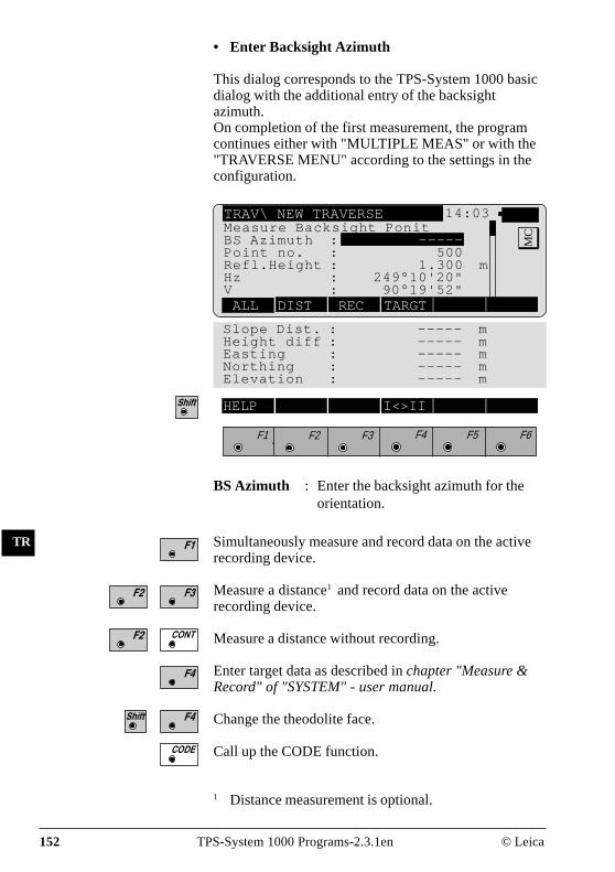
152 TPS-System 1000 Programs-2.3.1en © Leica
IV
EL
AH
OH
BS
SM
AS
FS
BL
HB
KM
FB
SA
TR
• Enter Backsight Azimuth
This dialog corresponds to the TPS-System 1000 basicdialog with the additional entry of the backsightazimuth.On completion of the first measurement, the programcontinues either with "MULTIPLE MEAS" or with the"TRAVERSE MENU" according to the settings in theconfiguration.
TRAV\ NEW TRAVERSE 14:03
MC
ALL DIST REC TARGT
Measure Backsight PonitBS Azimuth : -----Point no. : 500Refl.Height : 1.300 mHz : 249°10'20"V : 90°19'52"
Slope Dist. : ----- mHeight diff : ----- mEasting : ----- mNorthing : ----- mElevation : ----- m
F1 F2 F3 F4 F5 F6
HELP I<>II
Simultaneously measure and record data on the activerecording device.
Measure a distance1 and record data on the activerecording device.
Measure a distance without recording.
Enter target data as described in chapter "Measure &Record" of "SYSTEM" - user manual.
Change the theodolite face.
Call up the CODE function.
1 Distance measurement is optional.
BS Azimuth : Enter the backsight azimuth for theorientation.

© Leica TPS-System 1000 Programs-2.3.1en 153
IV
EL
AH
OH
BS
SM
AS
FS
BL
HB
KM
FB
SA
TR
Occupy station The instrument is set up for a new traverse point orsideshot. The angle measurement (distancemeasurement is optional) is made to a tie point or to thelast traverse point. This dialog corresponds to the TPS-System 1000 basic dialog. After the function has beenperformed, the station coordinates and orientation areset in the instrument.
TRAV\ OCCUPY TRAVERSE PT14:03
MC
ALL DIST REC TARGT SS
Slope Dist. : ----- mHeight diff : ----- mEasting : ----- mNorthing : ----- mElevation : ----- m
F1 F2 F3 F4 F5 F6
HELP I<>II
Station no. : 2Backsight : 1Inst.Height : 1.300Refl.Height : 1.300 mHz : 249°10'20"V : 90°19'52"
Station no. : Station point number.
Backsight : Backsight to tie point.
Simultaneously measure and record data on the activerecording device.
Measure a distance1 and record data on the activerecording device.
Measure a distance without recording.
Enter target data as described in chapter "Measure &Record" of "SYSTEM" - user manual.
1 Distance measurement is optional.

154 TPS-System 1000 Programs-2.3.1en © Leica
IV
EL
AH
OH
BS
SM
AS
FS
BL
HB
KM
FB
SA
TR
Selects the last measured sideshot or the last traversepoint as the new station.2
Change the theodolite face.
Proceed to the dialog "TRAVERSE MENU".
Call up the CODE function.
2 Only active if a sideshot point was measured.
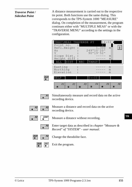
© Leica TPS-System 1000 Programs-2.3.1en 155
IV
EL
AH
OH
BS
SM
AS
FS
BL
HB
KM
FB
SA
TR
Traverse Point / Sideshot Point
A distance measurement is carried out to the respectivetie point. Both functions use the same dialog. Thiscorresponds to the TPS-System 1000 "MEASURE"dialog. On completion of the measurement, the programcontinues either with "MULTIPLE MEAS" or with the"TRAVERSE MENU" according to the settings in theconfiguration.
TRAV\MEAS TRAVERSE PT 14:03
MC
ALL DIST REC TARGT
Easting : ----- mNorthing : ----- mElevation : ----- m
F1 F2 F3 F4 F5 F6
HELP I<>II
Point no. : 20Refl.Height : 1.300 mHz : 249°10'20"V : 90°19'52"Slope Dist. : ----- mHeight diff : ----- m
Simultaneously measure and record data on the activerecording device.
Measure a distance and record data on the activerecording device.
Measure a distance without recording.
Enter target data as described in chapter "Measure &Record" of "SYSTEM" - user manual.
Change the theodolite face.
Exit the program.

156 TPS-System 1000 Programs-2.3.1en © Leica
IV
EL
AH
OH
BS
SM
AS
FS
BL
HB
KM
FB
SA
TR
Close traverse The program requires a closing point for comparisonwith the last traverse point measured. The default pointnumber is the starting point of the travers.
F1 F2 F3 F4 F5 F6
HELP
TRAV\ DEFINE CLOSING PT 14:03
MC
INPUT ST PT SEARC
Rec. device : Memory-CardSearch in : FILE02.GSI
Point/Code : 123
Enter coordinates using the standard input dialog.
Confirms the coordinates of the starting point.
Search coordinates in the database.
Exit the program.
TRAV\ CLOSURE RESULTS 14:03
MC
STORE PLOT MENU
AziCrdMiscl : 90°19'52"H Precision : 83569 mV Precision : 6528 m
F1 F2 F3 F4 F5 F6
HELP
No. of Pts. : 3Length : 1676.367 mCrd. miscl. : 0.040 mHgt. miscl. : 0.262 m∆Easting : -0.016 m∆Northing : -0.037 m
or

© Leica TPS-System 1000 Programs-2.3.1en 157
IV
EL
AH
OH
BS
SM
AS
FS
BL
HB
KM
FB
SA
TR
No. of Pts. : Number of traverse points
Length : Length of traverse
Crd. miscl. : Coordinate misclosure
Hgt.miscl. : Height misclosure
∆∆∆∆∆ Easting : Misclosure in easting
∆∆∆∆∆ Northing : Misclosure in northing
AziCrdMisc1 : Azimuth of coordinate misclosure
H Precision : Position precision =
traverse length=
Crd. misclosure
V Precision : Vertical precision =
height difference=
Hgt. misclosure
The results of the traverse are recorded in the file formeasurements on the active recording device.
Plot of the traverse.
Continue with the "TRAVERSE MENU".
Exit the program.
Continue with the "TRAVERSE MENU".

158 TPS-System 1000 Programs-2.3.1en © Leica
IV
EL
AH
OH
BS
SM
AS
FS
BL
HB
KM
FB
SA
TR
Examples
Codeblock with results of the traverse closure :
WI 41: Code 38WI 42: Number of traverse points.WI 43: Length of traverse (sum of legs).WI 44: Azimuth of misclosure
WI 41 Code 39WI 42 MisclosureWI 43: Misclosure eastingWI 44: Misclosure northingWI 45: Misclosure in height
WI 41 Code 40WI 42 Position precision (traverse length /
misclosure)WI 43: Vertical precision (height difference /
misclosure)
410010+00000038 42....+00000005 43....+01013515 44....+01928220
410011+00000039 42....+00000123 43....+00000045 44....+00000114 45....+00000087
410012+00000040 42....+00008239 43....+00010000
110015+00123456 25.143+14611200 84..40+00001215 85..40-0000315386..40+00403285 88..10+00001555
Measurementblock with the traverse StationCoordinates of station points
WI 11: Point numberWI 25: ∆Hz (correction of orientation)WI 84: E
0 easting coordinate
WI 85: N0 northing coordinate
WI 86: HeightWI 88: Instrument height

© Leica TPS-System 1000 Programs-2.3.1en 159
IV
EL
AH
OH
BS
SM
AS
FS
BL
HB
KM
FB
SA
TR
Plot Generates a plot showing the measurementconfiguration.
F1 F2 F3 F4 F5 F6
HELP
TRAV\ PLOT 14:03
MC
RESLT
N
Return to the dialog "CLOSURE RESULTS".

160 TPS-System 1000 Programs-2.3.1en © Leica
IV
EL
AH
OH
BS
SM
AS
FS
BL
HB
KM
FB
SA
TR
F1 F2 F3 F4 F5 F6
HELP
TRAV\ CONFIGURATION 14:03
MC
INFO DFLT YES
Two Faces : NOMult Meas : NOCode : 38Log File : OFFLog FlName : TRAVERSE.LOG
The "Configuration Editor" sets parameters for furtherprogram operations:
Two Faces : Set YES for dual-face measurement,NO for single-face.
Mult Meas : Set YES for the multiplemeasurement,NO for the single measurement.
Code : Input of code number for recordingresults (maximum 8 characters)
Log File : Set to ON, the program will recordmeasurement data in the Log Fileaccording to the format described onpage 163.
Log FlName : Enter the Log File Name.
Start the "Configuration Editor" from the "TRAVERSEMENU" dialog.
Displays date and version.
Configuration
Configuration Editor

© Leica TPS-System 1000 Programs-2.3.1en 161
IV
EL
AH
OH
BS
SM
AS
FS
BL
HB
KM
FB
SA
TR
Set all values to default. Default values are shown indialog on page 160.
Select (NO/YES, alpha-numeric/numeric input, ON/OFF).
Confirm displayed parameter and continues with the"TRAVERSE MENU".
Dual-face Measurement In the dual-face mode, the program will prompt formeasurements in both faces. When both measurementsare taken, the program will check the differencebetween the two. If the difference in angle is within 27'(0.5 gon) and the difference of two measured distancesis within 0.5 m (1.64 ft), the observations will beaveraged. These tolerances are used to avoid errors intarget identification. If exceeded an error message willbe displayed.
TRAV\ MULTIPLE MEAS 14:03M
C
MEAS CLEAR REC TARGT ACCEP
ØV : 103°45'25"ØSlope Dist : 50.125 m
Point no. : 500No. of Meas : 1σHZ : 0°00'30"σV : 0°00'22"σSlope Dist : 0.001 mØHz : 45°00'52"
F1 F2 F3 F4 F5 F6
HELP
Multiple Measurement The measurement to a point can be repeated as often asdesired to achieve a higher accuracy or reliability. Themean value of the measurements and the respectivestandard deviation is displayed.

162 TPS-System 1000 Programs-2.3.1en © Leica
IV
EL
AH
OH
BS
SM
AS
FS
BL
HB
KM
FB
SA
TR
Point no. : The target point number.
No. of Meas : Counter of the measurements.
σσσσσHz : Standard deviation of the horizontaldirection for a single measurement.
σσσσσV : Standard deviation of the verticalangle for a single measurement.
σσσσσSlope Dist : Standard deviation of the slopedistance for a single measurement.
ØHz : Mean value of the HZ-measurements.
ØV : Mean value of the HZ-measurements.
ØSlope Dist : Mean value of the slope distances.
Further measurements.
Delete all measurements of the current point and startagain.
Record the mean value of the measurements on theactive recording device. Return to the "TRAVERSEMENU" dialog.
Enter target data as described in chapter "Measure &Record" of "SYSTEM" - user manual.
Accept the mean values and return to the "TRAVERSEMENU".
© Leica TPS-System 1000 Programs-2.3.1en 163
IV
EL
AH
OH
BS
SM
AS
FS
BL
HB
KM
FB
SA
TR
Log File If "Log File" is set to ON the measurements and theresults are stored in the ASCII-file specified within the"Configuration Editor". This file is created in thedirectory LOG on the memory card. Subsequently, youcan read the memory card on your PC and obtain a hardcopy of the Log-file.
Data will always be appended to the specified Log-file.
The Log-file contains the following information:
Header The header line will contain the nameof this program, information about theinstrument, the name of the data fileand date and time.
Record Computed coordinates of traversepoints are continously stored. Theoption Close traverse in the"TRAVERSE MENU" (Dialog page148) displays and stores at any timethe coordinate - differences of traversepoints of which the coordinates areknown.

164 TPS-System 1000 Programs-2.3.1en © Leica
IV
EL
AH
OH
BS
SM
AS
FS
BL
HB
KM
FB
SA
TR
Leica VIP Traverse V 2.10Instrument : TCM1100, Serial 430000, Joe’s theodoliteUser Templ : User 1Meas. File : FILE01.GSIProgram Start : 02/23/1995 at 10:25
Backsight : 500Station : Pt.1
E= -0.679m N= 9.545m H= 400.062m hi= 1.530m
Station : Pt.2E=-13.462m N=10.528m H= 400.170m hi= 1.650m
Station : Pt.3E=26.513m N=16.821m H= 401.260m hi= 1.610m
Last Trav.Pt. : 501E= -77.949m N= 25.037m H= 399.923m
Closing Pt. : 501E= -78.016m N= 24.996m H= 400.181m
No. of Pts. : 4Length : 82.788mHor. miscl. : 0.047mVert. miscl. : 0.268mDEasting : -0.017mDNorthing : -0.031mAzi H.miscl : 226°51'25"H Precision : 2036V Precision : 2356
Typical log file entry in the "TRAVERSE"
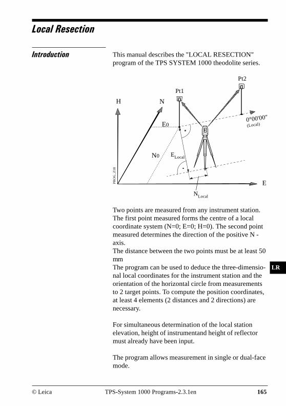
© Leica TPS-System 1000 Programs-2.3.1en 165
IV
EL
AH
OH
BS
SM
AS
FS
BL
HB
KM
FB
SA
PZ
LR
Local Resection
Introduction This manual describes the "LOCAL RESECTION"program of the TPS SYSTEM 1000 theodolite series.
PR
OG
_Z
18
E
H N
Pt1
Pt2
Two points are measured from any instrument station.The first point measured forms the centre of a localcoordinate system (N=0; E=0; H=0). The second pointmeasured determines the direction of the positive N -axis.The distance between the two points must be at least 50mmThe program can be used to deduce the three-dimensio-nal local coordinates for the instrument station and theorientation of the horizontal circle from measurementsto 2 target points. To compute the position coordinates,at least 4 elements (2 distances and 2 directions) arenecessary.
For simultaneous determination of the local stationelevation, height of instrumentand height of reflectormust already have been input.
The program allows measurement in single or dual-facemode.
NLocal
E0
N0 ELocal
0°00'00"(Local)

IV
EL
AH
OH
BS
SM
AS
FS
BL
HB
KM
FB
SA
PZ
LR
166 TPS-System 1000 Programs-2.3.1en © Leica
Station Data Enter station point number and height of the instrument.
F1 F2 F3 F4 F5 F6
HELP CONF
LRES\ STATION DATA 14:03
MCStation no. : Station2
Inst.Height : 1.555 m
Proceed to the dialog "MEASURE POINT 1".
Start the "CONFIGURATION"
Quit program .

© Leica TPS-System 1000 Programs-2.3.1en 167
IV
EL
AH
OH
BS
SM
AS
FS
BL
HB
KM
FB
SA
PZ
LR
Target Points This dialog is similar to the TPS System 1000’s basic"MEASURE MODE" dialog. Once the measurement tothe first and to the second point is taken, the programwill proceed to the dialog "RESULTS".
Simultaneously measure and record data on the activerecording device.
Measure a distance.
Record the measurement on the active recording device.
Enter target data as described in chapter "Measure &Record" of "SYSTEM" - user manual.
Change the theodolite face.
Accept the measurement.
Call up the CODE function, input of a code block.
LRES\ MEASURE POINT 1 14:03
MC
ALL DIST REC TARGT
Height diff : 1.002 mEasting : 231.463 mNorthing : 56.785 mElevation : 72.235 m
F1 F2 F3 F4 F5 F6
HELP I<>II
Point no. : 12Remark 1 : -----Refl.Height : 1.300 mHz : 2°10'20"V : 90°19'52"Horiz.Dist. : ----- m

IV
EL
AH
OH
BS
SM
AS
FS
BL
HB
KM
FB
SA
PZ
LR
168 TPS-System 1000 Programs-2.3.1en © Leica
Calculation In this dialog the calculated station coordinates areshown with orientation.
F1 F2 F3 F4 F5 F6
HELP
LRES\RESULTS <L.SQRS> 14:03
MCStation no. : 1
Easting : -3.369 mNorthing : 0.569 mElevation : 0.235 mOrientation : 135°34'56"
SET STORE
Station no : Station point number
Easting : Calculated E (local) for the station
Northing : Calculated N (local) for the station
Elevation : Calculated Elevation (local) for thestation
Orientation : Angular correction needed to orientthe instrument
Set orientation and station coordinates on theinstrument. Note that this key will end the program.
Record the following results on the active recordingdevice:
WI 11 Station Point NumberWI 25 Orientation correctionWI 84 Station EastingWI 85 Station NorthingWI 86 Station ElevationWI 87 Last reflector height usedWI 88 Instrument Height
Exit the program.

© Leica TPS-System 1000 Programs-2.3.1en 169
IV
EL
AH
OH
BS
SM
AS
FS
BL
HB
KM
FB
SA
PZ
LR
Configuration
Configuration Editor
F1 F2 F3 F4 F5 F6
HELP
LRES\ CONFIGURATION 14:03
MC
INFO DFLT YES
Start the "Configuration Editor" from the "STATIONDATA" dialog.
Two Faces : NO
The "Configuration Editor" sets parameters for furtherprogram operations:
Two Faces :YES for dual-face measurement,NO for single-face.
Displays date and version of the running application.
Set the value to the default. (Two Faces = NO, seedisplay above)
Store the current configuration and proceed to thedialog "STATION DATA".

IV
EL
AH
OH
BS
SM
AS
FS
BL
HB
KM
FB
SA
PZ
LR
170 TPS-System 1000 Programs-2.3.1en © Leica
Dual-face Measurement In the dual-face mode, the program will prompt formeasurements in both faces. When both measurementsare taken, the program will check the differencebetween the two. If the difference in angle is within 27'(0.5 gon) and the difference of two measured distancesis within 0.5 m (1.64 ft), the observations will beaveraged. These tolerances are used to avoid errors intarget identification. If exceeded an error message willbe displayed.

© Leica TPS-System 1000 Programs-2.3.1en 171
IV
EL
AH
OH
BS
SM
AS
FS
BL
HB
KM
FB
SA
PZ
RO
Road line
Introduction The manual describes the program "ROAD LINE" forthe Leica TPS 1000 series.
PR
OG
_Z
26
[km] 0 50 100 150 200 300
centre-lineoffset (+)
centre-lineoffset (-)
points to bestaked
The program is suitable for setting out points which aredetermined by chainage and centre-line offset along acalculated alignment. If V-alignments and cross-sections are defined for the alignment, the points can becalculated and set out spatially ("ROADSTAKEOUT").Conversely, if a point in the vicinity of the alignmenthas been determined by measurement, the chainage andcentre-line offset can be determined ("X-SECTIONCHECK").This version of "ROAD LINE" is only valid for a GSIconfiguration.

172 TPS-System 1000 Programs-2.3.1en © Leica
IV
EL
AH
OH
BS
SM
AS
FS
BL
HB
KM
FB
SA
PZ
RO
The program reads the geometrical elements of analignment from files expressed in GSI format. The datafor the alignment are grouped in accordance with thethree components of an alignment. The file names mustcomply with certain rules:
1. Hz-alignmentFile name:ALN?????.GSI
2. V-alignmentFile name:PRF?????.GSI
3. Cross sectionFile name:CRS?????.GSI
You can insert a permitted character for a DOS filename in place of a ? .
1. Permitted elements in the Hz-alignment
• Straight defined by chainage andcoordinates of tarting point
• Curve defined by chainage andcoordinates of starting pointRadius of arc (- = left-hand curve+ = right-hand curve)
• Spiral defined bychainage and coordinates ofstarting pointparameter A1 of spiral (negativeparameter = spiral into left-handcurve)
• End of project (EOP) chainage and coordinates ofend-point
1 A² = L x R where L = length of spiral; R = radius ofcurve

© Leica TPS-System 1000 Programs-2.3.1en 173
IV
EL
AH
OH
BS
SM
AS
FS
BL
HB
KM
FB
SA
PZ
RO
2. Permitted elements in V-alignments
• Straight defined bychainage and height of startingpoint
• Curve defined bychainage and height of startingpointradius of arc (- = crest + = dip)
• Parabola defined bychainage and height of startingpointparameters of parabola1 (- = crest+ = dip)
• End of project (EOP) chainage and height of end-point of gradient
3. Permitted elements in cross sections
• Chainage
• Offset
• Height difference relative to axis
To enter the data, you can use a PC and the programROADDATA.EXE supplied, or you can use the pro-gram FILE EDITOR on the TPS 1000.
1 2p x (H - H0) = (S - S
0)² S
0, H
0
station and height of vertex

174 TPS-System 1000 Programs-2.3.1en © Leica
IV
EL
AH
OH
BS
SM
AS
FS
BL
HB
KM
FB
SA
PZ
RO
Program concept The "ALIGNMENT CALCULATION " program onlypermits measurements in one face.
Before the program is started, the following proceduresare carried out:
1. Setting user profile and name of the data file.
2. Determining the instrument station and theorientation
"ROAD STAKEOUT" requires the following input:
1. Chainage for the point to be set out
2. Offset and height displacement of the point to be setout, or zero point of cross section relative to axis(optional)
3. Selection of a point on the cross section (optional)
On the basis of this input, the coordinates of the point tobe set out are determined and are transferred to theprogram "SETTING OUT" for post-processing.
The "X-SECTION CHECK" requires the followinginput:
1. Measurement to ground point
The parameters calculated and displayed arerespectively the chainage, the offset, and the heightdifference of the point measured with respect to thecentre-line.

© Leica TPS-System 1000 Programs-2.3.1en 175
IV
EL
AH
OH
BS
SM
AS
FS
BL
HB
KM
FB
SA
PZ
RO
Alignment
Selection of files The files with the definitions for the Hz-alignment, theV-alignment and the cross sections are selected. Thenames of the files must be in accordance with theguidelines laid down in section "Introduction".The Hz-alignment must always be selected. The choiceof a V-alignment and of transverse sections is optional.If no V-alignment is selected, points can only be setout or inspected in two dimensions. Without V-alignments, no transverse sections can be selected.
F1 F2 F3 F4 F5 F6
HELP CONF
ROADL\ SELECT ALN FILES 14:03
MCHoriz.Aln. : ALNTEMP
Vert. Aln. : PRFTEMPCross Secs : CRSTEMPLog FlName : ROAD.LOG
Horiz.Aln : Selects definition of Hz-alignment.
Vert. Aln : Selects definition of gradient (optio-nal)
Cross Secs : Selects definition of cross section.(optional)
Log FlName : Name of the log file in use.
Start the "Configuration".
Continues with dialog "CHECKING FILES".

176 TPS-System 1000 Programs-2.3.1en © Leica
IV
EL
AH
OH
BS
SM
AS
FS
BL
HB
KM
FB
SA
PZ
RO
Checking files The files selected are inspected for formal input errorsand for geometrical deviations.
The job identification for the three input files isinspected, as are possible errors in the data format e.g.missing or incorrect word index (WI). Errors areindicated by appropriate messages. The inspection canbe continued or interrupted. If serious formal errorsare found, the inspection is aborted.
Geometrical deviations include the tangent directionsof adjacent elements and the chord lengths of elements.Deviations which exceed the permitted tolerance aredisplayed. The inspection of the files can be continuedor interrupted.
After inspection, the program returns to Dialog 2. Theinput values can be corrected, either on a PC using theprogram "ROADDATA.EXE" or on the TPS1000 usingthe programm "FILE EDITOR".
ROADL\ CHECKING FILES 14:03
MC
NO YES
F1 F2 F3 F4 F5 F6
ALN: Deflection toleranceexceeded at chainage 89°18'00".Difference in direction is0°00'27". Override?

© Leica TPS-System 1000 Programs-2.3.1en 177
IV
EL
AH
OH
BS
SM
AS
FS
BL
HB
KM
FB
SA
PZ
RO
Exceeding the permitted tolerance is accepted and theinspection is continued. Longitudinal errors aredistributed proportionally by changing the scale.Because of the variable curvature, deviations in thetangential direction are not taken into account.
When the program is called up again, the permittedtolerance is inspected only if the data have beenchanged or if the tolerance limits have been changed.

178 TPS-System 1000 Programs-2.3.1en © Leica
IV
EL
AH
OH
BS
SM
AS
FS
BL
HB
KM
FB
SA
PZ
RO
Program flow
Chainage and centre-lineoffset
Hght. Shift : 0.000 mChaingeIncr : 100.000 m
F1 F2 F3 F4 F5 F6
HELP
ROADL\ CHAINAGE &OFFSET 14:03
MCChainage : 0.000 m
Element : POBOffset : 0.000 mHghtOffset : 0.000 m
CHECK CH--> <--CH XSEC
The dialog is used to enter the longitudinal and crosssection data for a point to be set out, or to call thefunction "X-SECTION CHECK".
Chainage : The present chainage for"STAKEOUT".After setting-out is completed, thechainage is automatically changed tothe next value divisible byChaingeIncr.The chainage of the main points(change of elements) is displayedindependently of ChaingeIncr. Anydesired chainage can be keyed in.For the function "X-SECTIONCHECK" the values displayed anddata from the cross section do notinfluence the calculation in the "X-SECTION CHECK".

© Leica TPS-System 1000 Programs-2.3.1en 179
IV
EL
AH
OH
BS
SM
AS
FS
BL
HB
KM
FB
SA
PZ
RO
Element : The element type on which thechainage displayed is located.The elements are output in full. Bothadjacent elements are displayed in themain points.
Offset : Horizontal displacement (offset) ofthe point to be set out in relation to thecentre line.
HghtOffset : Height displacement of the point to beset out in relation to the centre line.(The amount of the verticaldisplacement is also taken intoaccount.)
Hght. Shift : All heights in the alignment arechanged by this amount. The valuecan only be changed in the dialog"CONFIGURATION".
ChaingeIncr : The chainage difference when settingout. The chainage is automaticallyincremented by this amount.
Calls the function "X-SECTION CHECK".
Displays the next chainage up which is divisible byChaingeIncr. If the end of the alignment is overshot, awarning is given once. After the end of the alignment,the calculation is based on the tangent of the lastelement.
Displays the next chainage down which is divisible byChaingeIncr. If there is a shortfall at the beginning ofthe alignment, a warning is given once. Before thebeginning of the alignment, the calculation is based onthe tangent of the first element.
Calls the dialog "CROSS SECTIONS".
Calls the dialog "POINT COORDINATES" in order todisplay the coordinates of the point to be set out. Fromthere, calls the program "STAKEOUT".

180 TPS-System 1000 Programs-2.3.1en © Leica
IV
EL
AH
OH
BS
SM
AS
FS
BL
HB
KM
FB
SA
PZ
RO
Cross sections • Selecting points in the cross section
For setting out, points on the defined cross section canbe selected.
ROADL\ CROSS SETIONS 14:03
MC
<-- <-- CENTR --> -->
Hght. Shift : 0.999999 m
1R*Chainage : 100.000Cross Sect. : +TMPL0001∆CL Offset : 0.000 m∆CL HGTDiff : 0.000 mOffset : 3.000 m
HghtOffset : 0.000 m
F1 F2 F3 F4 F5 F6
HELP PLOT
1R : Numbering the profile points from thecentre line outwards: 1L, 2L, 3L, etc.for points to the left; 1R, 2R, 3R etc.for points to the right. The centre ofthe cross-sectional profile is numbered0C. Points already set out are marked* . The display bar displays ingraphical form the position of thepoint in the profile.
Chainage : Chainage currently valid.
Cross Sect. : Name of the valid cross section. Adifferent profile can be searched for.
∆∆∆∆∆CL Offset : Horizontal distance from the centre ofthe profile to the current profile point.
∆∆∆∆∆CL Hgt Diff : Vertical distance from the centre ofthe profile to the current profile point.

© Leica TPS-System 1000 Programs-2.3.1en 181
IV
EL
AH
OH
BS
SM
AS
FS
BL
HB
KM
FB
SA
PZ
RO
Offset : Horizontal displacement (centre-lineoffset) of the centre of the X-sectionby this amount.
HghtOffset : Height displacement of the centre ofthe X-section(The value of the HghtOffset is alsotaken into account.)
Hght. Shift : All heights in the alignment arechanged by this amount. The valuecan only be altered in this dialog.
Displays far-left profile point.
Displays profile point one place further to the left.
Displays centre of profile.
Displays profile point one place further to the right.
Displays far-right profile point.
Displays diagram of cross section.
Calls dialog "POINT COORDS" to display coordinatesof point to be set out. From there, calls program"STAKEOUT".

182 TPS-System 1000 Programs-2.3.1en © Leica
IV
EL
AH
OH
BS
SM
AS
FS
BL
HB
KM
FB
SA
PZ
RO
• Plot
A simple diagram of the cross section is displayed. Thevertical scale is exaggerated three times.
F1 F2 F3 F4 F5 F6
HELP
ROADL\ PLOT 14:03
MC
XSEC
Returns to dialog "CROSS SECTION".
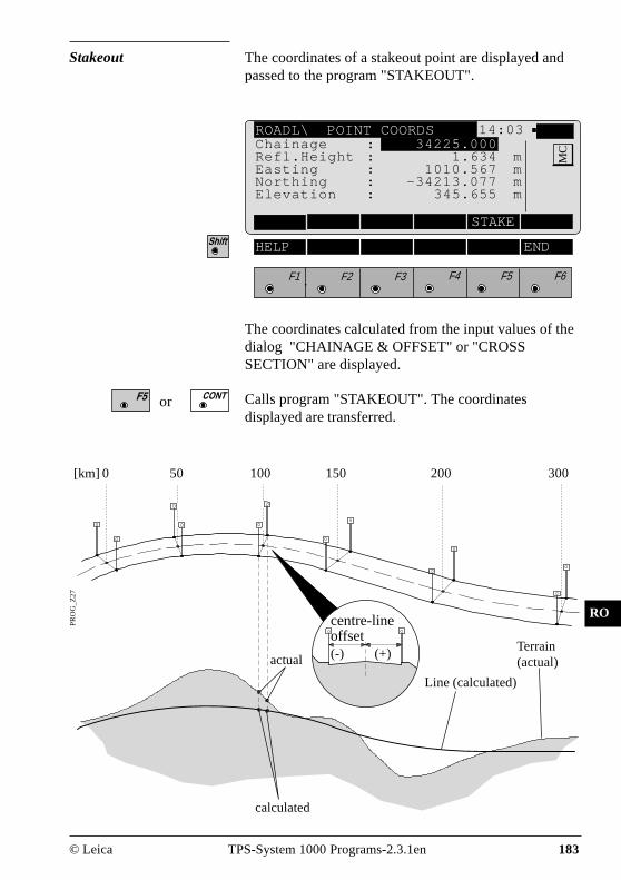
© Leica TPS-System 1000 Programs-2.3.1en 183
IV
EL
AH
OH
BS
SM
AS
FS
BL
HB
KM
FB
SA
PZ
RO
The coordinates of a stakeout point are displayed andpassed to the program "STAKEOUT".
Stakeout
F1 F2 F3 F4 F5 F6
HELP END
ROADL\ POINT COORDS 14:03
MCChainage : 34225.000
Refl.Height : 1.634 mEasting : 1010.567 mNorthing : -34213.077 mElevation : 345.655 m
STAKE
The coordinates calculated from the input values of thedialog "CHAINAGE & OFFSET" or "CROSSSECTION" are displayed.
Calls program "STAKEOUT". The coordinatesdisplayed are transferred.
or
[km] 0 50 100 150 200 300
PR
OG
_Z
27
calculated
Line (calculated)
actual
centre-lineoffset(-) (+)
Terrain(actual)

184 TPS-System 1000 Programs-2.3.1en © Leica
IV
EL
AH
OH
BS
SM
AS
FS
BL
HB
KM
FB
SA
PZ
RO
X-section Check
The function "X-SECTION CHECK" is called in thedialog "CHAINAGE & OFFSET".Any desired point in the topography is measured.The program calculates
- the chainage,- the offset and- the height difference
of the point in relation to the defined centre line.
[km] 0 50 100 150 200 300
PR
OG
_Z
28
∆H
projected(calculated)
built(actual)
+2,5
-2,5
+1,2 -3,8

© Leica TPS-System 1000 Programs-2.3.1en 185
IV
EL
AH
OH
BS
SM
AS
FS
BL
HB
KM
FB
SA
PZ
RO
F1 F2 F3 F4 F5 F6
HELP I<>II END
ROADL\ X-SECTION CHECK 14:03
MCPoint no. : 12
Remark 1 : -----Refl.-Height : 1.567 mHZ : 135°40'47"V : 91°34'50"Horiz.Dist : 88°55'58" ALL DIST REC TARGT IMPOR
Measures and records in the active file and goes on todisplay the chainage and the offset relative to thecentre-line definition.
Measures the distance. Stores the measurement in theactive file and goes on to display the chainage and theoffset of the point.
Measures the distance. Does not store the measurement.Goes on to display the chainage and the offset relativeto the centre-line definition.
Enters the target-point data. This function is describedin chapter "Measure & Record" of "SYSTEM" - usermanual.
For manually entering the coordinates of a point, or forreading in the active coordinate file. Displays thechainage and the offset of the point.
Calls the code function.
This displays the defined standard measuring dialog,which may be different from the one depicted above.

186 TPS-System 1000 Programs-2.3.1en © Leica
IV
EL
AH
OH
BS
SM
AS
FS
BL
HB
KM
FB
SA
PZ
RO
Display of results
Displayed are- chainage,- offset and- height offset
in relation to the centre line.
Hght. Shift : 0.000 mChaingeIncr : 100.000 m
F1 F2 F3 F4 F5 F6
HELP STORE
ROADL\ CHAINAGE &OFFSET 14:03
MC
CHECK CH--> <--CH XSEC
Chainage : The chainage of the point measured isdisplayed.
Element : The type of element on which thepoint measured is located.The names of the elements aredisplayed without abbreviation. In themain points, the two adjacent elementsare displayed.
Offset : Horizontal displacement (offset) ofthe point measured in relation to thecentre line. If several results areavailable (eg, at tight corners) thepoint with the shortest distance to thecentre line is indicated. By changingthe calculation limits in theconfiguration, the calculation rangecan be limited and as a result, thefound stationing can be influenced.
Chainage : 23.456 mElement : Straight lineOffset : -3.553 mHghtOffset : 0.254 m

© Leica TPS-System 1000 Programs-2.3.1en 187
IV
EL
AH
OH
BS
SM
AS
FS
BL
HB
KM
FB
SA
PZ
RO
HghtOffset : Height displacement of the pointmeasured in relation to the centre line.(The amount of the verticaldisplacement is also taken intoaccount.)
Hght. Shift : All heights in the alignment arechanged by this amount. The valuecan only be changed in the dialog"CONFIGURATION".
ChaingeIncr : The chainage difference when settingout. The chainage is automaticallyincremented by this amount.
Re-calls the function "X-SECTION CHECK".
See section "Chainage and centre-line offset".
See section "Chainage and centre-line offset".
The result of the road station and offset is stored.
See section "Chainage and centre-line offset".
See section "Chainage and centre-line offset".

188 TPS-System 1000 Programs-2.3.1en © Leica
IV
EL
AH
OH
BS
SM
AS
FS
BL
HB
KM
FB
SA
PZ
RO
Configuration
Configuration Editor
Start the "Configuration Editor" from the "SELECTALN FILES " dialog.
ROADL\ CONFIGURATION 14:03
MC
INFO DFLT EDIT
3D Stake : ONLog File : OFFLog FlName : ROAD.LOG
BaseChainge : 0.000End Chainge : 0.000ChaingeIncr : 100.000 mHght. Shift : 0.000 mDeflct.Tol. : 0°00'16''ChaingeTol. : 10 m
F1 F2 F3 F4 F5 F6
HELP
The parameters defining the further course of theprogram are determined in the "Configuration Editor":
BaseChainge : Setting the starting point forcalculation when in the "X-SECTIONCHECK" function.
EndChainage : Setting the end point for calculation inthe "X-SECTION CHECK" function.
ChaingeIncr : Difference in chainage when settingout. The chainage is automaticallyincremented by this amount.
Hght. Shift : All heights in the alignment arechanged by this amount. The valuecan be changed only when you are inthis dialog.

© Leica TPS-System 1000 Programs-2.3.1en 189
IV
EL
AH
OH
BS
SM
AS
FS
BL
HB
KM
FB
SA
PZ
RO
Deflct.Tol. : Permissible deviation of the tangentdirections for adjacent elements. Amessage appears if this value isexceeded. The input is always inmilligon.
ChaingeTol. : Permissible deviation of the (chord)length of an element and of thedistance calculated from the end-pointcoordinates, expressed in the lengthunits set. A message appears if thisvalue is exceeded.
3D Stake : ON for setting out positions andheights. The height can be set out onlyif the V-alignment has been defined.OFF for setting out only positions.Neither a V-alignment nor a typicalcross-section can be set out.
Log File : Set to ON, the program will recordmeasurement data in a log file in theformat described on page 190.
Log FlName : Enter the log file name.
Displays date and version of the program.
Sets standard values . The values are displayed indialog on page 188.
Accepts and stores parameters displayed. Continues todisplay "SELECT ALN FILES".

190 TPS-System 1000 Programs-2.3.1en © Leica
IV
EL
AH
OH
BS
SM
AS
FS
BL
HB
KM
FB
SA
PZ
RO
Log File If "Log File" is set to ON the measurements and theresults are stored in the ASCII-file specified within the"Configuration Editor". This file is created in thedirectory LOG on the memory card. Subsequently, youcan read the memory card on your PC and obtain a hardcopy of the Log-file.
Data will always be appended to the specified Log-file.
The Log-file contains the following information:
Header includes:- the program used,- information about the instrument,- the file to store the measurementdata,
- the date and the time.
Configuration the name of the input files for:- the Hz-alignment,- the V-alignment and- the transverse section.
Measurement - Instrument station with coordinatesand instrument height.
- Stakeout point with chainage,- offset1 and height displacement2
relative to centre line,- comparison values from planning,and associated differences.
For the alignment inspection,- the coordinates of the pointmeasured are stored along with
- the associated station,- the offset and- the height difference.

© Leica TPS-System 1000 Programs-2.3.1en 191
IV
EL
AH
OH
BS
SM
AS
FS
BL
HB
KM
FB
SA
PZ
RO
1 This value results from- the displacement of the zero point of the profile and- the displacement taken from the transverse profile.
2 This value results from- the displacement of the zero point of the profile and- the displacement taken from the transverse profile- the height displacement in the configuration.
Leica VIP Road line V 2.10Instrument : TCM1800, Serial 410000, TCM1800User templ. : User 1Meas. file : FILE01.GSIProgram Start : 02/07/1996 at 10:43
Hz-alignment : ALNMSPLZ.GSIV-alignment : PRFMSPLZ.GSICross Sect. : CRSMSPLZ.GSI
Station no. : TRASSEE= -10.0000m N= 25.0000m ELV= 400.0000m hi= 0.0000m
Point no. : 3386Chainage : 49.2812, Offset= -4.9130m, HghtOffset= 0.2473mAs Measured : E= -11.6393m, N= 27.8821m, ELV= 400.8301m
Point no. : 3386Chainage : 49.2812, Offset= -4.9130m, HghtOffset= 0.2473mDesign : E= -11.6391m, N= 27.8823m, ELV= 400.8301mStaked : E= -11.6394m, N= 27.8830m, ELV= 400.8266mDeltas : dE= 0.0004m, dN= -0.0007m, dELV= 0.0035m
Example of a log file for the program "ROAD LINE"

192 TPS-System 1000 Programs-2.3.1en © Leica
IV
EL
AH
OH
BS
SM
AS
FS
BL
HB
KM
FB
SA
PZ
RO
Data format This section describes the input-data format for the Hz-alignment, the V-alignment and the cross section. Toenter the data, you can use a PC and the program"ROADDATA.EXE" supplied, or you can use theprogram "FILE EDITOR" on the TPS 1000.
Hz-alignment The definition of the road elements is based on the mainpoints (= starting and finishing points of thegeometrical element) and on the element parameters.Refer to the example in the next diagram.
The alignment starts at main point no. 1 and finishes atmain point no. 4.Here, the geometrical elements are:Straight - curve - straight.The curve radius is R.
The starting point of a geometrical element is also thefinishing point of the preceding adjacent element.
PR
OG
_Z
21
3 4
2
1
R
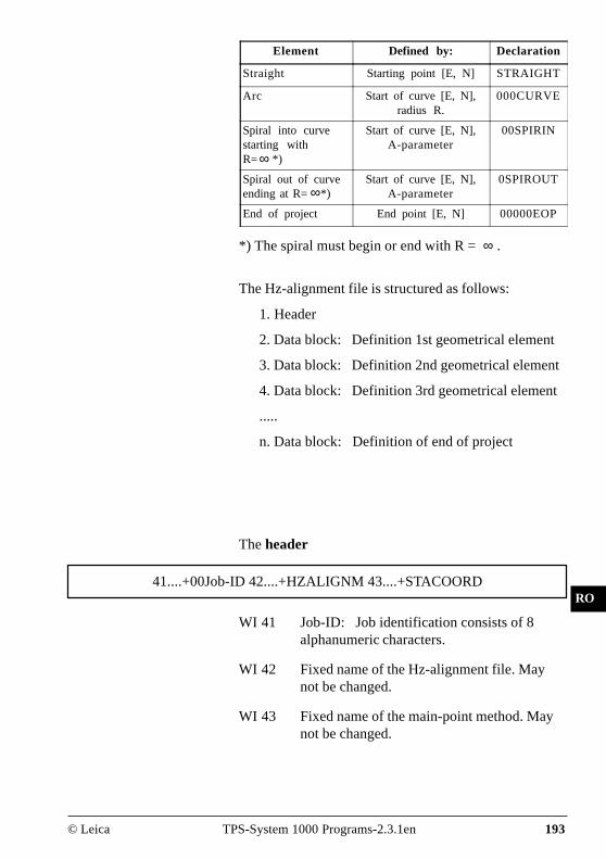
© Leica TPS-System 1000 Programs-2.3.1en 193
IV
EL
AH
OH
BS
SM
AS
FS
BL
HB
KM
FB
SA
PZ
RO
The header
41....+00Job-ID 42....+HZALIGNM 43....+STACOORD
WI 41 Job-ID: Job identification consists of 8alphanumeric characters.
WI 42 Fixed name of the Hz-alignment file. Maynot be changed.
WI 43 Fixed name of the main-point method. Maynot be changed.
Element Defined by: Declaration
Straight Starting point [E, N] STRAIGHT
Arc Start of curve [E, N],radius R.
000CURVE
Spiral into curvestarting withR= *)
Start of curve [E, N],A-parameter
00SPIRIN
Spiral out of curveending at R= *)
Start of curve [E, N],A-parameter
0SPIROUT
End of project End point [E, N] 00000EOP
∞
∞
*) The spiral must begin or end with R = ∞ .
The Hz-alignment file is structured as follows:
1. Header
2. Data block: Definition 1st geometrical element
3. Data block: Definition 2nd geometrical element
4. Data block: Definition 3rd geometrical element
.....
n. Data block: Definition of end of project

194 TPS-System 1000 Programs-2.3.1en © Leica
IV
EL
AH
OH
BS
SM
AS
FS
BL
HB
KM
FB
SA
PZ
RO
The data block
11....+0STATION 71....+GEOM_ELE 72....+RAD/PARA 73....+TEMPLATE81..10+00000000 82..10+00000000
WI 11 STATION: Chainage at the start of theelement. 8-digit number.
WI 71 GEOM_ELE: Geometrical elementaccording to table page 190 (STRAIGHT,000CURVE, 00SPIRIN, 0SPIROUT,00000EOP).
WI 72 RAD/PARA: Arc radius or A-parameter forthe spirals. 8-digit number.If WI 71 = STRAIGHT / 00000EOP, then WI72 = 00000NON.Sign:+, for curves to the right (centre of circle tothe right of the alignment), -, for curves to the left (centre of circle to theleft of the alignment).
WI 73 TEMPLATE: Name/number of the cross-sectional profile for the geometrical elementdefined in WI 71. 8 alphanumeric characters.The following combinations are reserved andare not to be used: 00000NON andLASTTMPL.
WI 81 E-coordinate of the main point (startingpoint, start of curve, end point according totable page 190). 8-digit number.
WI 82 N-coordinate of the main point (startingpoint, start of curve, end point according totable page 190). 8-digit number.

© Leica TPS-System 1000 Programs-2.3.1en 195
IV
EL
AH
OH
BS
SM
AS
FS
BL
HB
KM
FB
SA
PZ
RO
Also:
• The header is always at the beginning of the file.
• The Hz-alignment file must always contain at leasttwo elements.
• The units and decimal places used in the WIs 11 and72 are in accordance with the definitions in WIs 81and 82.
• The chainage is produced from the sum of theelement lengths.
• A cross-sectional profile may be assigned more thanonce.
• Geometrical elements can be combined freely, forexample as:- Transition curve (straight - spiral - arc)- Vertex spiral ( straight - spiral into curve- spiral out of curve - straight)
Unusual applications are also possible:
- Breakpoint (straight - straight)- Right-angle (straight - straight, or straight - 90°
arc - straight)
• There is no limitation on the size of the Hz-alignmentfile. As a result, as many data blocks as required canbe entered if a file is created on the PC using theDOS program "ROADDATA.EXE". If a file iscreated/edited using the program "FILE EDITOR"on the TPS1000 there is a limitation of 200 datablocks.
Check your data for errors (typing errors, signs etc.)before you load it into the memory card.
The program supports the user during the setting-out bycontrolling the length of curves. It compares the lengthof the element from the chainage (WI 11) with thecalculated main-point values, thus enabling input errorsin the chainage or in the coordinates to be detected.However, the signs of arcs and of spirals are notchecked (see example below).

196 TPS-System 1000 Programs-2.3.1en © Leica
IV
EL
AH
OH
BS
SM
AS
FS
BL
HB
KM
FB
SA
PZ
RO
PR
OG
_Z
21
2
1
43
-R
+R
If the wrong sign (-R) is used, the arc is mirroredbetween the main points 2 and 3.
410001+Example1 42....+HZALIGNM 43....+STACOORD
110002+00000000 71....+STRAIGHT 72....+00000NON 73....+Tmpl012581..10+02000000 82..10+06000000
110003+00198832 71....+00SPIRIN 72....-00122474 73....+Tmpl012381..10+02186841 82..10+06068005
110004+00348832 71....+000CURVE 72....-00100000 73....+Tmpl012381..10+02307751 82..10+06150344
110005+00450725 71....+0SPIROUT 72....-00100000 73....+Tmpl012381..10+02304071 82..10+06247816
110006+00550725 71....+STRAIGHT 72....+00000NON 73....+Tmpl012581..10+02227794 82..10+06310759
110007+00714138 71....+00SPIRIN 72....+00054772 73....+Tmpl012481..10+02086275 82..10+06392465
110008+00789138 71....+000CURVE 72....+00040000 73....+Tmpl012481..10+02037807 82..10+06445859
110009+00824376 71....+0SPIROUT 72....+00044721 73....+Tmpl012481..10+02048886 82..10+06478120
110010+00874376 71....+STRAIGHT 72....+00000NON 73....+Tmpl012581..10+02094478 82..10+06496445
110011+01127904 71....+00000EOP 72....+00000NON 73....+Tmpl012581..10+02344154 82..10+06540469
Example: S-line with a straight connection

© Leica TPS-System 1000 Programs-2.3.1en 197
IV
EL
AH
OH
BS
SM
AS
FS
BL
HB
KM
FB
SA
PZ
RO
The project start is at the nadir. After the first straightthere follows a left curve, then a right curve. There arealso spirals and a straight between the arcs.
The cross sections are assigned as follows:Straight Tmpl0125Left curve Tmpl0123Right curve Tmpl0124
The last character at the end of each data line must be aspace (ASCII character 32).
WI 11 and WI 41: The block number is located fromposition 3 to 6.
of the geometrical elements. The starting point of oneelement is also the finishing point of the previouselement.
• V-alignment
The V-alignment definition (= V-alignment)
The V-alignment is defined with the main points (1 - 6).The main points form the starting and finishing points
PR
OG
_Z
23
12 3
4 56
Straight Straight Straight
Parabola+p
Parabola-p

198 TPS-System 1000 Programs-2.3.1en © Leica
IV
EL
AH
OH
BS
SM
AS
FS
BL
HB
KM
FB
SA
PZ
RO
Element Defined by: Declaration
Straight Starting point [chainage, H] STRAIGHT
Arc Start of curve [chainage, H],radius R.
000CURVE
Parabola Start of curve [chainage, H],parabola parameter p
PARABOLA
End of project Finishing point [chainage, H] 00000EOP
The Header
41....+00Job-ID 42....+0VALIGNM 43....+STACOORD
WI 41 Job-ID: Job identification consists of 8alphanumeric characters.
WI 42 Fixed name of the V-alignment file. May notbe changed.
WI 43 Fixed name of the main-point method. Maynot be changed.
The V-alignment file is structured as follows:
1. Header
2. Data block: Definition 1st geometrical element
3. Data block: Definition 2nd geometrical element
4. Data block: Definition 3rd geometrical element
.....
n. Data block: Definition of end of project

© Leica TPS-System 1000 Programs-2.3.1en 199
IV
EL
AH
OH
BS
SM
AS
FS
BL
HB
KM
FB
SA
PZ
RO
The Data block
11....+0STATION 71....+GEOM_ELE 72....+RAD/PARA 83..10+00HEIGHT
WI 11 STATION: Chainage (from the Hz-alignment) at the start of the element. 8-digitnumber.
WI 71 GEOM_ELE: Geometrical elementaccording to table page 195 (STRAIGHT,000CURVE, PARABOLA, 00000EOP).
WI 72 RAD/PARA: Arc radius or parabolaparameter. 8-digit number.If WI 71 = STRAIGHT / 00000EOP, then WI72 = 00000NON.Sign: "+" = dip, "-" = crest
WI 83 HEIGHT: Height H of the main point(starting point, start of curve, end point, inaccordance with table page 195). 8-digitnumber.
Also:
• The header is always at the beginning of a data file.
• The V-alignment file must be composed of at leasttwo parts (starting- and finishing point).
• The units and decimal places used in the WIs 11 and72 are in accordance with the definition in WI 83.
• The chainage is given by the sum of the horizontalelement lengths.
• Geometrical elements can be combined freely.
• There is no limitation on the size of the V-alignmentfile. As a result, as many data blocks as required canbe entered if a file is created on the PC using theDOS program "ROADDATA.EXE". If a file iscreated/edited using the program "FILE EDITOR"on the TPS1000 there is a limitation of 200 datablocks.
Check your data for errors (typing errors, signs etc.)before you load it into the memory card.

200 TPS-System 1000 Programs-2.3.1en © Leica
IV
EL
AH
OH
BS
SM
AS
FS
BL
HB
KM
FB
SA
PZ
RO
An example of the wrong sign used with an arc ofradius R or with the parabola parameter p:
410001+Example1 42....+0VALIGNM 43....+STACOORD
110002+00000000 71....+STRAIGHT 72....+00000NON 83..10+00400000
110003+00300000 71....+PARABOLA 72....-01142936 83..10+00422500
110004+00500000 71....+STRAIGHT 72....+00000NON 83..10+00420000
110005+00550000 71....+PARABOLA 72....+02091126 83..10+00415000
110006+00850000 71....+STRAIGHT 72....+00000NON 83..10+00406522
110007+01127904 71....+00000EOP 72....+00000NON 83..10+00418605
Example: Crest and dip
The last character in each data line must always be aspace (ASCII character 32).
WI 11 and WI 41: The block number is located fromposition 3 to 6.
If the wrong sign (+R/+p) is used, the summit becomesa trough.
41
3
+R/+p
2-R/-p
PR
OG
_Z
24

© Leica TPS-System 1000 Programs-2.3.1en 201
IV
EL
AH
OH
BS
SM
AS
FS
BL
HB
KM
FB
SA
PZ
RO
• Cross sections
The points in the cross section are defined inaccordance with:- the centre-line offset sCLO (neg.: pt. left / pos.: pt.
right) and
- the height difference sH related to the alignmentpoint (neg.: pt. lower / pos.: pt. higher thanalignment)
The template file is structured as follows:
1. Header
2. Data block: Cross section 1 / point no. 1
3. Data block: Cross section 2 / point no. 2
4. Data block: Cross section 3 / point no. 3
.....
n. Data block: Cross section x / point no. y
Element Defined by: Declaration
Height difference Planned height differencewith respect to alignment
-
Centerline offset Planned centre-line offset -
Aspect:chainage increasing
PR
OG
_Z
24
2
1 3
4
5
left rightalignment
sCLO (pos.)
s∆H (neg.)

202 TPS-System 1000 Programs-2.3.1en © Leica
IV
EL
AH
OH
BS
SM
AS
FS
BL
HB
KM
FB
SA
PZ
RO
The Header
41....+00Job-ID 42....+TEMPLATE
WI 41 Job-ID: Job identification consists of 8alphanumeric characters.
WI 42 Fixed name of the template file. May not bechanged.
The data block
11....+TMPLNAME 35..10+DISTANCE 36..10+000HDIFF
WI 11 TMPLNAME: Name/number of the crosssection, consisting of 8 alphanumericcharacters. The following designations arereserved and may not be used: 00000NONand LASTTMPL.
WI 35 DISTANCE: Centre-line offset of atransverse-profile point. 8-digit number.
WI 36 HDIFF: Height difference of a transverse-profile point. 8-digit number
Also:
• The header must always be at the start of a data file.
• The file must contain at least one cross section.
• Profile points belonging to the same cross sectionmust always be together in a single data set. Thepoints need not be sorted within the data set.
• The individual transverse-profile data sets need notbe sorted within the template file.
• For a cross section file there is a limitation of 200data blocks. The maximum number of points in across section is 48.

© Leica TPS-System 1000 Programs-2.3.1en 203
IV
EL
AH
OH
BS
SM
AS
FS
BL
HB
KM
FB
SA
PZ
RO
Recommendation:If in general you prepare an empty template (only thezero point), you can at any time choose this templatein order to manually enter points or to call up axispoints. Call this template something like AXIS orEMPTY.
Check your data for errors (typing errors, signs etc.)before you load it into the memory card.
The last character at the end of each data line mustalways be a space (ASCII-character 32).
WI 11 and WI 41: The block number is located fromposition 3 to 6.
Example: Cross section
41....+Example1 42....+TEMPLATE
110002+Tmpl0123 35..10-00013000 36..10-00003000
110003+Tmpl0123 35..10-00010000 36..10-00005000
110004+Tmpl0123 35..10-00004000 36..10-00000100
110005+Tmpl0123 35..10+00004000 36..10+00000100
110006+Tmpl0123 35..10+00010000 36..10-00006000
110007+Tmpl0123 35..10+00013000 36..10-00003500
110008+Tmpl0124 35..10-00012000 36..10-00002000
110009+Tmpl0124 35..10-00011000 36..10-00004000
110010+Tmpl0124 35..10-00004000 36..10+00000100
110011+Tmpl0124 35..10+00004000 36..10-00000100
110012+Tmpl0124 35..10+00011000 36..10-00005000
110013+Tmpl0124 35..10+00012000 36..10-00002500

204 TPS-System 1000 Programs-2.3.1en © Leica
IV
EL
AH
OH
BS
SM
AS
FS
BL
HB
KM
FB
SA
PZ
RO
The Road - Data Entryprogram
The Leica "ROADDATA.EXE" for providingsetting-out data files
Once the alignment has been designed using road-design software, the resulting data consist of mainpoints, element parameters and cross sections. Thesedata must be brought into a structure which can beloaded into the memory card. There are two ways toproduct the three setting-out data files (Hz-alignmentfile, V-alignment file and transverse-profile file):
a) writing an individually-customised program toautomatically generate and convert the necessarydata
b) entering the data by hand into the Leica"ROADDATA.EXE" program. The program offers aconvenient way of entering the values by offeringsuitable menu controls. The program reformats thedata into the structure required.
Once the three setting-out data files are ready, all youneed to do is to transfer the data into the memory card,using a suitable transfer program.
Using the "ROADDATA.EXE" program
• Copy the program from the diskette to your harddisk, using the DOS command
COPY
and from there into e.g. disk drive C:\.
• Start the program with the command
C:\>roaddata
• Follow the menu directives. An integrated Helpfunction gives you support, particularly when you areusing the keyboard commands.

© Leica TPS-System 1000 Programs-2.3.1en 205
IV
EL
AH
OH
BS
SM
AS
FS
BL
HB
KM
FB
SA
PZ
LB
TB
CO
COGO
Introduction This manual describes the "COGO" program of theTPS SYSTEM 1000 theodolite series.The following provides a general overview of theindividual COGO functions.
The "Inverse" routine computes the direction anddistance between two points.
The "Traverse" routine computes a new coordinatepoint given a direction and distance from a known point(Polar plotting).
The "Intersections" routine computes:• Bearing-Bearing intersections,• Bearing-Distance intersections or• Distance-Distance intersections.
The function "Offsets" consists of the followingsubfunctions:• "Distance point straight line"
Calculates the difference in length/abscissa and thelateral deviation/ordinate with reference to a basisline emanating from a known point.
• "Orthogonal point calculation"A new point can be calculated which emanates froma basis line using the difference in length/abscissaand the lateral deviation/ordinate.
The "Point Arc" routine computes a radius point givenany three points.

206 TPS-System 1000 Programs-2.3.1en © Leica
IV
EL
AH
OH
BS
SM
AS
FS
BL
HB
KM
FB
SA
PZ
LB
TB
CO
The point coordinates can either:• be determined by measurement,• entered manually using a keyboard or• read from the memory card.
Data, both measured and read from the file, can bemixed. This means, however, that station coordinatesand orientation have to be correctly set.
Directions and distances can be entered manually,called up or freshly determined. The values can then beamended by means of multiplication, division, additionand subtraction.
The program "Stakeout" can be called up directly fromthe individual result dialog boxes (if available) in orderto set out the points immediately.The program "Stakeout" assumes that the instrument isset and oriented to a known point.

© Leica TPS-System 1000 Programs-2.3.1en 207
IV
EL
AH
OH
BS
SM
AS
FS
BL
HB
KM
FB
SA
PZ
LB
TB
CO
Configuration
Start the "Configurations Editor" from the "COGOMENU " dialogue.
COGO\ CONFIGURATION 14:03
MCDirec. Type: Bearing
Offset : YES
INFO DFLT LIST
F1 F2 F3 F4 F5 F6
HELP
Displays date and version.
Set all values to default. The values are shown in thedialogue above.
Accept displayed values and proceed to the dialogue"COGO MENU".
Exit the program.
The "Configuration Editor" sets parameters for furtherprogram operations:
Direc. Type : BearingAzimuth
Offset : YES entering a paralleldisplacement is possibleNO entering a paralleldisplacement is not possible
s

208 TPS-System 1000 Programs-2.3.1en © Leica
IV
EL
AH
OH
BS
SM
AS
FS
BL
HB
KM
FB
SA
PZ
LB
TB
CO
Function selection(COGO Menu)
COGO\ COGO MENU 14:03
F1 F2 F3 F4 F5 F6
HELP CONF
MCInverse 0
Traverse 1Intersections 2Offsets 33 Point Arc 4End COGO 5
Call up the "Configuration-Editor".

© Leica TPS-System 1000 Programs-2.3.1en 209
IV
EL
AH
OH
BS
SM
AS
FS
BL
HB
KM
FB
SA
PZ
LB
TB
CO
N
Inverse (polarcalculation)
Computes distance and direction between two points.
E
NH
CO
GO
_0
1
Azimuth
Magnetic bearing
1
2
Horizontal distance
Search : • Direction (magnetic bearing orazimuth)
• Horizontal distance
Given : • point 1 (y, x)• point 2 (y, x)
Station coordinates and orientation need to have beenset correctly before the coordinates of point 1 (and/or 2)can be determined by measurement.

210 TPS-System 1000 Programs-2.3.1en © Leica
IV
EL
AH
OH
BS
SM
AS
FS
BL
HB
KM
FB
SA
PZ
LB
TB
CO
Call up the function in the "COGO MENU" dialog.
COGO\ INVERSE FROM 14:03
INPUT MEAS SEARCαNUM
F1 F2 F3 F4 F5 F6
HELP
MCRec. device : Memory Card
Search in : FILE01.GSI
Point/Code : 58
Manual entering of the first (second) point of thestraight line. The standard TPS 1000 input dialog boxappears.
Measuring the first (second) point of the straight line.This function is described in chapter "Measure &Record" (Measurement dialogue) of the "System" - usermanual.
Search for the coordinates of the first (second) point inthe coordinate file. This function is described in chapter"Setups" (Import function) of the "System" - usermanual.
Exit the program.
or

© Leica TPS-System 1000 Programs-2.3.1en 211
IV
EL
AH
OH
BS
SM
AS
FS
BL
HB
KM
FB
SA
PZ
LB
TB
CO
The following dialog box shows the result of the polarcalculation from both the given points:
COGO\ INVERSE RESULTS 14:03
F1 F2 F3 F4 F5 F6
HELP
MCFrom : 1010
To : 1020Southwest : 89°37'45"Horiz.Dist. : 31.237 m
From : Display of point number of the firstpoint
To : Display of point number of the secondpoint
Southwest : Display of magnetic bearing.If " Azimuth " is selected in theconfiguration during "Direc. Type:",then the azimuth will be displayedbetween both the points.
Horiz.Dist. : Display of horizontal distancebetween the points
Return to "COGO MENU".
Exit the program.
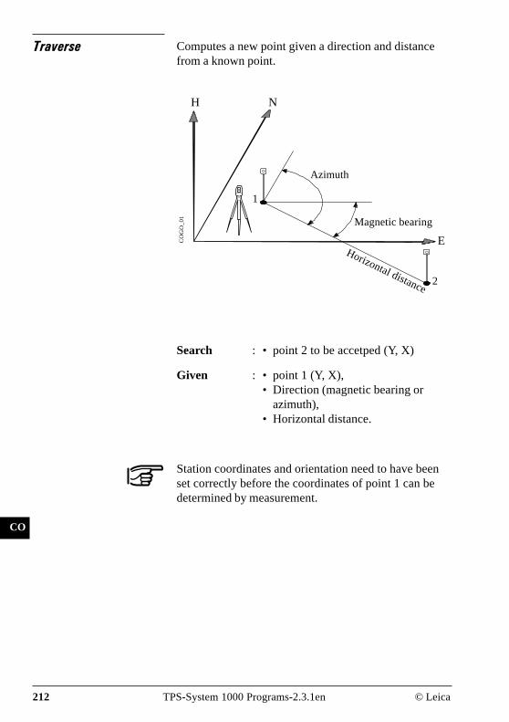
212 TPS-System 1000 Programs-2.3.1en © Leica
IV
EL
AH
OH
BS
SM
AS
FS
BL
HB
KM
FB
SA
PZ
LB
TB
CO
Traverse Computes a new point given a direction and distancefrom a known point.
N
E
NH
CO
GO
_0
1Azimuth
Magnetic bearing
1
2
Horizontal distance
Search : • point 2 to be accetped (Y, X)
Given : • point 1 (Y, X),• Direction (magnetic bearing or
azimuth),• Horizontal distance.
Station coordinates and orientation need to have beenset correctly before the coordinates of point 1 can bedetermined by measurement.
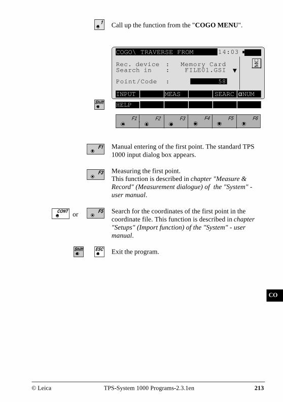
© Leica TPS-System 1000 Programs-2.3.1en 213
IV
EL
AH
OH
BS
SM
AS
FS
BL
HB
KM
FB
SA
PZ
LB
TB
CO
Call up the function from the "COGO MENU".
COGO\ TRAVERSE FROM 14:03
INPUT MEAS SEARCαNUM
F1 F2 F3 F4 F5 F6
HELP
MCRec. device : Memory Card
Search in : FILE01.GSI
Point/Code : 58
Manual entering of the first point. The standard TPS1000 input dialog box appears.
Measuring the first point.This function is described in chapter "Measure &Record" (Measurement dialogue) of the "System" -user manual.
Search for the coordinates of the first point in thecoordinate file. This function is described in chapter"Setups" (Import function) of the "System" - usermanual.
Exit the program.
or

214 TPS-System 1000 Programs-2.3.1en © Leica
IV
EL
AH
OH
BS
SM
AS
FS
BL
HB
KM
FB
SA
PZ
LB
TB
CO
Defining direction bymagnetic bearing
If " Bearing" is selected in the configuration during"Direc. Type:", then the following dialog box appears:
Determining the direction by means of the function"Polar calculation"(refer to chapter "Inverse").
INPUT Enter quadrant, magnetic bearing.RCALL Call up of a direction which has been
previously stored using the function"Polar calculation".
Accept displayed values and proceed with dialogue"TRAVERSE" (page 218).
COGO\ TRAVERSE 14:03
F1 F2 F3 F4 F5 F6
HELP MODIF
MCDirection to Traverse
Quadrant : 1NorthEast : 0°00'00"Offset : 0.000 m
INV RCALL EDIT
Quadrant : Enter quadrant:1 = NorthEast2 = SouthEast3 = SouthWest4 = NorthWest
Northeast : Enter magnetic bearing
Offset : Enter parallel displacement.Only active if "YES" is entered in theconfiguration during "Offset:"Left = negative parallel offsetRight = positive parallel offset

© Leica TPS-System 1000 Programs-2.3.1en 215
IV
EL
AH
OH
BS
SM
AS
FS
BL
HB
KM
FB
SA
PZ
LB
TB
CO
Changing the direction see under existing dialog box"MODIFY BEARING"
Exit the program.
COGO\ MODIFY BEARING 14:03
F1 F2 F3 F4 F5 F6
HELP
MCNorthEast : 0°00'00"
Multiply : -----Divide : -----Add : 0°00'00"Subtract : 0°00'00"NorthEast : 0°00'00"
EDIT
NorthEast : Display of entered magnetic bearings(ref. to dialogue "TRAVERSE", page214)
Multiply : Entering multiplication factor
Divide : Entering division factor
Add : Entering angle for a correction to theright
Subtract : Entering angle for a correction to theleft
NorthEast : Display of corrected magneticbearings
Accept displayed values and proceed with dialogue"TRAVERSE" (page 218).

216 TPS-System 1000 Programs-2.3.1en © Leica
IV
EL
AH
OH
BS
SM
AS
FS
BL
HB
KM
FB
SA
PZ
LB
TB
CO
Defining direction byAzimuth
If "Azimuth " is selected in the configuration during"Direc. Type:", then the following dialog box appears:
COGO\ TRAVERSE 14:03
F1 F2 F3 F4 F5 F6
HELP MODIF
MCDirection to Traverse
Azimuth : 0°00'00"Offset : 0.000 m
INV RCALL EDIT
Determining the direction by means of the function"Polar calculation" (refer to chapter "Inverse").
INPUT Entering AzimuthRCALL Call up of a direction which has been
previously stored using the function"Polar calculation".
Accept displayed values and proceed with dialogue"TRAVERSE" (page 218).
Changing the direction (refer to dialogue "MODIFYAZIMUTH ", page 217)
Exit the program.
Azimuth : Entering Azimuth
Offset : Entering parallel displacement.Only active if "YES" is entered in theconfiguration during "Offset:"Left = negative parallel offsetRight = positive parallel offset

© Leica TPS-System 1000 Programs-2.3.1en 217
IV
EL
AH
OH
BS
SM
AS
FS
BL
HB
KM
FB
SA
PZ
LB
TB
CO
COGO\ MODIFY AZIMUTH 14:03
F1 F2 F3 F4 F5 F6
HELP
MCAzimuth : 0°00'00"
Multiply : -----Divide : -----Add : 0°00'00"Subtract : 0°00'00"Azimuth : 0°00'00"
EDIT
Azimuth : Display of entered Azimuth (ref. to"TRAVERSE", page 216)
Multiply : Entering multiplication factor
Divide : Entering division factor
Add : Entering angle for a correction to theright
Subtract : Entering angle for a correction to theleft
Azimuth : Display of corrected Azimuth
Accept displayed values and proceed to dialogue"TRAVERSE" (page 218).

218 TPS-System 1000 Programs-2.3.1en © Leica
IV
EL
AH
OH
BS
SM
AS
FS
BL
HB
KM
FB
SA
PZ
LB
TB
CO
Defining horizontaldistance
COGO\ TRAVERSE 14:03
F1 F2 F3 F4 F5 F6
HELP MODIF
MCDistance to Traverse
Horiz.Dist. : 0.000 mOffset : 0.000 m
INV RCALL EDIT
Horiz Dist : Entering horizontal distance
Offset : Entering parallel displacement.Only active if "YES" is entered in theconfiguration during "Offset:"Left = negative parallel offsetRight = positive parallel offset
Determining the distance by means of the function"Polar calculation" (refer to chapter "Inverse").
INPUT Entering horizontal distanceRCALL Call up of a distance which has been
previously stored using the function"Polar calculation".
Accept displayed values and proceed to dialogue"TRAVERSE RESULTS" (page 220).
Changing the distance (refer to dialogue "MODIFYDISTANCE", page 219).
Exit the program.

© Leica TPS-System 1000 Programs-2.3.1en 219
IV
EL
AH
OH
BS
SM
AS
FS
BL
HB
KM
FB
SA
PZ
LB
TB
CO
COGO\ MODIFY DISTANCE 14:03
F1 F2 F3 F4 F5 F6
HELP
MCHoriz.Dist. : 0.000 m
Multiply : -----Divide : -----Add : 0.000 mSubtract : 0.000 mHoriz.Dist. : 0.000 m
EDIT
Horiz.Dist. : Display of entered horizontal distance(refer to dialogue "TRAVERSE",page 218)
Multiply : Entering multiplication factor
Divide : Entering division factor
Add : Entering distance for a positivecorrection
Subtract : Entering distance for a negativecorrection
Horiz.Dist. : Display of corrected horizontaldistance
Accept displayed values and proceed to dialogue"TRAVERSE RESULTS" (page 220).

220 TPS-System 1000 Programs-2.3.1en © Leica
IV
EL
AH
OH
BS
SM
AS
FS
BL
HB
KM
FB
SA
PZ
LB
TB
CO
The following dialog box shows the result of thetraverse:
COGO\ TRAVERSE RESULTS 14:03
F1 F2 F3 F4 F5 F6
HELP
MCPoint no. : -----
Easting : 0.000 mNorthing : 0.000 mElevation : -----
STORE STAKE
Point no. : Entering point number of the point tobe accepted
Easting : Display of east coordinate
Northing : Display of north coordinate
Elevation : Entering height (optional)
The following results have been stored in the activemeasurement data file:
WI 11 Station Point NumberWI 81 Easting coordinateWI 82 Northing coordinateWI 83 Elevation (optional)
If "Point no." has not be entered, the button is notoccupied.
Call up the program "Stakeout".The program "Plotting" assumes that the instrument isset and oriented to a known point.If "Point no." has not be entered, the button is notoccupied.
Return to "COGO MENU".
Exit the program.

© Leica TPS-System 1000 Programs-2.3.1en 221
IV
EL
AH
OH
BS
SM
AS
FS
BL
HB
KM
FB
SA
PZ
LB
TB
CO
Intersections
Call up the function from the "COGO MENU".
COGO\ INTERSECTIONS 14:03
F1 F2 F3 F4 F5 F6
HELP
MCBearing - Bearing 0
Bearing -Distance 1Distance-Distance 2End Intersections 3

222 TPS-System 1000 Programs-2.3.1en © Leica
IV
EL
AH
OH
BS
SM
AS
FS
BL
HB
KM
FB
SA
PZ
LB
TB
CO
N
Bearing-BearingIntersection
NH
CO
GO
_0
2
E
Search : • Coordinates of intersection(Y, X)
Given : • point 1 (Y, X), direction (magneticbearing or azimuth)
• point 2 (Y, X), direction (magneticbearing or azimuth)
Station coordinates and orientation need to have beenset correctly before the coordinates of point 1 (and/or 2)can be determined by measurement.
Azimuth
positive paralleloffset
Intersection
Magneticbearing
Direction (here:Azimuth =Magneticbearing)
12

© Leica TPS-System 1000 Programs-2.3.1en 223
IV
EL
AH
OH
BS
SM
AS
FS
BL
HB
KM
FB
SA
PZ
LB
TB
CO
COGO\ BEARING #1 FROM 14:03
INPUT MEAS SEARCαNUM
F1 F2 F3 F4 F5 F6
HELP
MCRec. device : Memory Card
Search in : FILE01.GSI
Point/Code : 58
Manual entering of the first (second) point. Thestandard TPS 1000 input dialog box appears.
Measuring the first (second) point of the straight line.This function is described in chapter "Measure &Record" (Measurement dialogue) of the "System" - usermanual.
Search for the coordinates of the first (second ) point inthe coordinate file. This function is described in chapter"setups" (Import function) of the "System"-usermanual.
Exit the program.
or
Call up the function from the menu"INTERSECTIONS ".

224 TPS-System 1000 Programs-2.3.1en © Leica
IV
EL
AH
OH
BS
SM
AS
FS
BL
HB
KM
FB
SA
PZ
LB
TB
CO
If " Bearing" is selected in the configuration during"Direc. Type:", then the following dialog box appears:
COGO\ BEARING #1 14:03
F1 F2 F3 F4 F5 F6
HELP MODIF
MCDirection from first point
Quadrant : 1NorthEast : 0°00'00"Offset : 0.000 m
INV RCALL EDIT
Quadrant : Enter quadrant (First or secondstraight lines)1 = Northeast2 = Southeast3 = Southwest4 = Northwest
NorthEast : Enter magnetic bearing (First orsecond straight lines)If "Azimuth " is selected in theconfiguration during "Direc.Type:",then the azimuth of the first straightline (or the second straight line) canbe entered.
Offset : Entering parallel displacement.Only active if "YES" is entered in theconfiguration during "Offset:"Left = negative parallel offsetRight = positive parallel offset
Determining the direction by means of the function"Polar calculation" (refer to chapter "Inverse").

© Leica TPS-System 1000 Programs-2.3.1en 225
IV
EL
AH
OH
BS
SM
AS
FS
BL
HB
KM
FB
SA
PZ
LB
TB
CO
INPUT Enter bearing, mangnetic bearing resp.azimuth (if "Azimuth " is selected inthe configuration during "Direc.Type:"
RCALL Call up of a direction which has beenpreviously stored using the function"Polar calculation".
Accept displayed values
Changing the direction (as dialog box "MODIFYBEARING", page 215 resp. "MODIFY AZIMUTH",page 217)
Exit the program.

226 TPS-System 1000 Programs-2.3.1en © Leica
IV
EL
AH
OH
BS
SM
AS
FS
BL
HB
KM
FB
SA
PZ
LB
TB
CO
The following dialog box shows the result of thebearing-bearing intersection:
COGO\BRG-BRG RESULTS 14:03
F1 F2 F3 F4 F5 F6
HELP
MCPoint no. : -----
Easting : 0.000 mNorthing : 0.000 mElevation : -----
STORE STAKE
Point no. : Entering point number of the bearing-bearing
Easting : Display of east coordinate
Northing : Display of north coordinate
Elevation : Entering height (optional)
The following results have been stored in the activemeasurement data file:
WI 11 Station Point NumberWI 81 Easting coordinateWI 82 Northing coordinateWI 83 Elevation (optional)
If "Point no." has not be entered, the button is notoccupied.
Call up the program "Stakeout".The program "Plotting" assumes that the instrument isset and oriented to a known point.If "Point no." has not be entered, the button is notoccupied.
Return to "INTERSECTIONS ".
Exit the program.

© Leica TPS-System 1000 Programs-2.3.1en 227
IV
EL
AH
OH
BS
SM
AS
FS
BL
HB
KM
FB
SA
PZ
LB
TB
CO
Search : • Bearing-bearing coordinatesS1 and S2 (Y, X)
Given : • point 1 (Y, X), direction(magnetic bearing or azimuth)
• point 2 (Y, X), radius
Station coordinates and orientation need to have beenset correctly before the coordinates of point 1 (and/or 2)can be determined by measurement.
Bearing-DistanceIntersection
NH N
ECO
GO
_0
32
positive paralleloffset
Radius
S2
S1
1
Direction (here:Azimuth = Magneticbearing)

228 TPS-System 1000 Programs-2.3.1en © Leica
IV
EL
AH
OH
BS
SM
AS
FS
BL
HB
KM
FB
SA
PZ
LB
TB
CO
COGO\ BEARING FROM 14:03
INPUT MEAS SEARCαNUM
F1 F2 F3 F4 F5 F6
HELP
MCRec. device : Memory Card
Search in : FILE01.GSI
Point/Code : 58
Manual entering of the first point (or circle centrepoint). The standard TPS 1000 input dialog boxappears.
Measuring the first point (or circle centre point). Thisfunction is described in chapter "Measure & Record"(Measurement dialogue) of the "System"-user manual.
Search for the coordinates of the first point (or circlecentre point) in the coordinate file. This function isdescribed in chapter "Setups" (Import function) of the"System"-user manual.
Exit the program.
or
Call up the function from the menu"INTERSECTIONS ".

© Leica TPS-System 1000 Programs-2.3.1en 229
IV
EL
AH
OH
BS
SM
AS
FS
BL
HB
KM
FB
SA
PZ
LB
TB
CO
If " Bearing" is selected in the configuration during"Direc. Type:", then the following dialog box appears:
COGO\BEARING-DISTANCE 14:03
F1 F2 F3 F4 F5 F6
HELP MODIF
MCDirection from bearing point
Quadrant : 1NorthEast : 0°00'00"Offset : 0.000 m
INV RCALL EDIT
Quadrant : Enter quadrant:1 = Northeast2 = Southeast3 = Southwest4 = Northwest
NorthEast : Enter magnetic bearingIf " Azimuth " is selected in theconfiguration during "Direc. Type:",then the azimuth of the straight linecan be entered.
Offset : Entering parallel displacement.Only active if "YES" is entered in theconfiguration during "Offset:"Left = negative parallel offsetRight = positive parallel offset
Determining the direction by means of the function"Polar calculation" (refer to chapter "Inverse").

230 TPS-System 1000 Programs-2.3.1en © Leica
IV
EL
AH
OH
BS
SM
AS
FS
BL
HB
KM
FB
SA
PZ
LB
TB
CO
INPUT Enter bearing, mangnetic bearingresp. azimuth (if "Azimuth " isselected in the configuration during"Direc. Type:"
RCALL Call up of a direction which has beenpreviously stored using the function"Polar calculation".
Accept displayed values
Changing the direction (as dialog box "MODIFYBEARING", page 215 resp. "MODIFY AZIMUTH",page 217)
Exit the program.

© Leica TPS-System 1000 Programs-2.3.1en 231
IV
EL
AH
OH
BS
SM
AS
FS
BL
HB
KM
FB
SA
PZ
LB
TB
CO
Enter distance from point:
COGO\BEARING-DISTANCE 14:03
F1 F2 F3 F4 F5 F6
HELP MODIF
MCDistance from point
Horiz.Dist. : 0.000 m
INV RCALL EDIT
Horiz.Dist. : Entering radius
Determining the radius by means of the function "Polarcalculation" (refer to chapter "Inverse").
INPUT Entering radiusRCALL Call up of a radius which has been
previously stored using the function"Polar calculation".
Accept displayed values
Changing the direction (as dialog box "MODIFYDISTANCE", page219).
Exit the program.

232 TPS-System 1000 Programs-2.3.1en © Leica
IV
EL
AH
OH
BS
SM
AS
FS
BL
HB
KM
FB
SA
PZ
LB
TB
CO
COGO\ BRG-DIST RESULTS 14:03
F1 F2 F3 F4 F5 F6
HELP
MCPoint no. : -----
Easting : 0.000 mNorthing : 0.000 mElevation : -----
OTHER STORE STAKE
The following dialog box shows the result of thebearing-distance intersection:
Point no. : Entering point number of the bearing-bearing
Easting : Display of east coordinate
Northing : Display of north coordinate
Elevation : Entering height (optional)
Changing between both solutions
The following results have been stored in the activemeasurement data file:
WI 11 Station Point NumberWI 81 Easting coordinateWI 82 Northing coordinateWI 83 Elevation (optional)
If "Point no." has not be entered, the button is notoccupied.
Call up the program "Stakeout".The program "Plotting" assumes that the instrument isset and oriented to a known point.If "Point no." has not be entered, the button is notoccupied.
Return to "INTERSECTIONS ".
Exit the program.

© Leica TPS-System 1000 Programs-2.3.1en 233
IV
EL
AH
OH
BS
SM
AS
FS
BL
HB
KM
FB
SA
PZ
LB
TB
CO
Distance-DistanceIntersection
Search : • Bearing-bearing coordinatesS1 and S2 (Y, X)
Given : • point 1 (Y, X), radius 1• point 2 (Y, X), radius 2
Station coordinates and orientation need to have beenset correctly before the coordinates of point 1 and/or 2can be determined by measurement.
ECO
GO
_0
4
NH N
1
Radius 1
Radius 2
2
S1
S2

234 TPS-System 1000 Programs-2.3.1en © Leica
IV
EL
AH
OH
BS
SM
AS
FS
BL
HB
KM
FB
SA
PZ
LB
TB
CO
COGO\ DISTANCE #1 FROM 14:03
INPUT MEAS SEARCαNUM
F1 F2 F3 F4 F5 F6
HELP
MCRec. device : Memory Card
Search in : FILE01.GSI
Point/Code : 58
Manual entering of the first circle centre point (2nd
circle centre point). The standard TPS 1000 inputdialog box appears.
Measuring the first circle centre point (2nd circle centrepoint). This function is described in chapter "Measure& Record" (Measurement dialogue) of the "System"-user manual.
Search for the coordinates of the first circle centre point(2nd circle centre point) in the coordinate file. Thisfunction is described in chapter "Setup" (Importfunction) in the "System" - user manual.
Exit the program.
or
Call up the function from the menu"INTERSECTIONS ".

© Leica TPS-System 1000 Programs-2.3.1en 235
IV
EL
AH
OH
BS
SM
AS
FS
BL
HB
KM
FB
SA
PZ
LB
TB
CO
Enter distance from points:
COGO\ DISTANCE-DISTANCE 14:03
F1 F2 F3 F4 F5 F6
HELP MODIF
MCDistance from first point
Horiz.Dist. : 0.000 m
INV RCALL EDIT
Horiz.Dist. : Entering distance from first point (2nd
point)
Determining the radius by means of the function "Polarcalculation" (refer to chapter "Inverse").
INPUT Entering radiusRCALL Call up of a radius which has been
previously stored using the function"Polar calculation".
Accept displayed values
Changing the direction (as dialog box "MODIFYDISTANCE", page219).
Exit the program.

236 TPS-System 1000 Programs-2.3.1en © Leica
IV
EL
AH
OH
BS
SM
AS
FS
BL
HB
KM
FB
SA
PZ
LB
TB
CO
The following dialog box shows the result of thedistance/distance intersection:
COGO\ DIST-DIST RESULTS 14:03
F1 F2 F3 F4 F5 F6
HELP
MCPoint no. : -----
Easting : 0.000 mNorthing : 0.000 mElevation : -----
OTHER STORE STAKE
Point no. : Entering point number of the bearing-bearing
Easting : Display of east coordinate
Northing : Display of north coordinate
Elevation : Entering height (optional)
Changing between both solutions
The following results have been stored in the activemeasurement data file:
WI 11 Station Point NumberWI 81 Easting coordinateWI 82 Northing coordinateWI 83 Elevation (optional)
If "Point no." has not be entered, the button is notoccupied.
Call up the program "Stakeout".The program "Plotting" assumes that the instrument isset and oriented to a known point.If "Point no." has not be entered, the button is notoccupied.
Return to "INTERSECTIONS ".
Exit the program.

© Leica TPS-System 1000 Programs-2.3.1en 237
IV
EL
AH
OH
BS
SM
AS
FS
BL
HB
KM
FB
SA
PZ
LB
TB
CO
Offsets
Call up the function in the "COGO MENU".
COGO\ OFFSETS 14:03
F1 F2 F3 F4 F5 F6
HELP
MCDistance--Offset 0
Set Point by Dist--Offset 1End Offsets 2

238 TPS-System 1000 Programs-2.3.1en © Leica
IV
EL
AH
OH
BS
SM
AS
FS
BL
HB
KM
FB
SA
PZ
LB
TB
CO
N
Search : • Difference in length/abscissa (L)• Lateral deviation/ordinate (Q)• Base point coordinates (Y, X)
Given : • Baseline Start Point 1 (Y, X),• Baseline End Point 2 (Y, X),• lateral point 3 (Y, X)
Station coordinates and orientation need to have beenset correctly before the coordinates of point 1resp. 2and/or point 3 can be determined by measurement.
Explanation of the polarity rule of L and QDuring entering, the polarity is based on the straightline 1 -> 2.+ Q Parallel displacement to the right- Q Parallel displacement to the left+ L Displacement from basis point 1 in the directionof basis point 2- L Displacement from basis point 1 in the opposite
direction to basis point 2
Distance-Offset
ECO
GO
_0
5
H N
1
2
3
QL
Base point

© Leica TPS-System 1000 Programs-2.3.1en 239
IV
EL
AH
OH
BS
SM
AS
FS
BL
HB
KM
FB
SA
PZ
LB
TB
CO
COGO\ BASELINE START PT. 14:03
INPUT MEAS SEARCαNUM
F1 F2 F3 F4 F5 F6
HELP
MCRec. device : Memory Card
Search in : FILE01.GSI
Point/Code : 58
Manual entering of the baseline start point resp. thebaseline end point (or the lateral point) . The standardTPS 1000 input dialog box appears.
Measuring the baseline start point resp. the baseline endpoint (or the lateral point).This function is described inchapter "Measure & Record" (Measurement dialogue)of the "System"-user manual.
Search for the coordinates of baseline start point resp.the baseline end point (or the lateral point) in thecoordinate file. This function is described in chapter"Setup" (Import function) of the "System"-user manual.
Exit the program.
or
Call up the function from the menu "OFFSETS".

240 TPS-System 1000 Programs-2.3.1en © Leica
IV
EL
AH
OH
BS
SM
AS
FS
BL
HB
KM
FB
SA
PZ
LB
TB
CO
The following dialog box shows the results:
COGO\ OFFSET RESULTS 14:03
F1 F2 F3 F4 F5 F6
HELP
MCPoint no. : -----
Easting : 0.000 mNorthing : 0.000 mElevation : -----Distance : 0.000 mOffset : 0.000 m
NEW STORE STAKE
Point no. : Entering point number of the basepoint
Easting : Display of east coordinate
Northing : Display of north coordinate
Elevation : Entering height (optional)
Distance : Display difference in length/abscissa(L)
Offset : Display lateral deviation/ordinate (Q)
Entering the new lateral point with reference to thealready existing basis line.
The following results have been stored in the activemeasurement data file:
WI 11 Station Point NumberWI 81 Easting coordinateWI 82 Northing coordinateWI 83 Elevation (optional)
If "Point no." has not be entered, the button is notoccupied.

© Leica TPS-System 1000 Programs-2.3.1en 241
IV
EL
AH
OH
BS
SM
AS
FS
BL
HB
KM
FB
SA
PZ
LB
TB
CO
Call up the program "Stakeout".The program "Plotting" assumes that the instrument isset and oriented to a known point.If "Point no." has not be entered, the button is notoccupied.
Return to the menu "OFFSETS".
Exit the program.
Search : • Lateral point 3 coordinates (Y, X)
Given : • Baseline Start Point 1 (Y, X),• Baseline End Point 2 (Y, X),• Difference in length/abscissa (L)• Lateral deviation/ordinate (Q)
Station coordinates and orientation need to have beenset correctly before the coordinates of point 1resp. point2 can be determined by measurement.
N
ECO
GO
_0
5
H N
1
2
3
QL
Orthogonal pointcalculation

242 TPS-System 1000 Programs-2.3.1en © Leica
IV
EL
AH
OH
BS
SM
AS
FS
BL
HB
KM
FB
SA
PZ
LB
TB
CO
Explanation of the polarity rule of L and QDuring entering, the polarity is based on the straightline 1 -> 2.+ Q Parallel displacement to the right- Q Parallel displacement to the left+ L Displacement from basis point 1 in the directionof basis point 2- L Displacement from basis point 1 in the opposite
direction to basis point 2
Call up the function in the menu "OFFSETS".
COGO\ BASELINE START PT. 14:03
INPUT MEAS SEARCαNUM
F1 F2 F3 F4 F5 F6
HELP
MCRec. device : Memory Card
Search in : FILE01.GSI
Point/Code : 58
Manual entering of the baseline start point (or thebaseline end point). The standard TPS 1000 inputdialog box appears.
Measuring the baseline start point (or the baseline endpoint). This function is described in chapter "Measure& Record" (Measurement dialogue) of the "System"-user manual.
Search for the coordinates of baseline start point (or thebaseline end point) in the coordinate file. This functionis described in chapter "Setup" (Import function) of the"System"-user manual.
Exit the program.
or

© Leica TPS-System 1000 Programs-2.3.1en 243
IV
EL
AH
OH
BS
SM
AS
FS
BL
HB
KM
FB
SA
PZ
LB
TB
CO
Enter distance along baseline (L):
COGO\DISTANCE FROM START14:03
F1 F2 F3 F4 F5 F6
HELP MODIF
MCDistance along baseline
Horiz.Dist. : 0.000 m
INV RCALL EDIT
Horiz.Dist. : Enter distance along baseline (L)
Determining the distance along baseline (L) by meansof the function "Polar calculation" (refer to chapter"Inverse").
INPUT Entering distance along baselineRCALL Call up of a distance along baseline
which has been previously storedusing the function "Polarcalculation".
Accept displayed values
Changing the direction (as dialog box "MODIFYDISTANCE", page219).
Exit the program.

244 TPS-System 1000 Programs-2.3.1en © Leica
IV
EL
AH
OH
BS
SM
AS
FS
BL
HB
KM
FB
SA
PZ
LB
TB
CO
Enter lateral deviation/distance from start (Q):
COGO\ OFFSET 14:03
F1 F2 F3 F4 F5 F6
HELP MODIF
MCPerpendicular offset from BL
Horiz.Dist. : 0.000 m
INV RCALL EDIT
Horiz.Dist. : Enter lateral deviation/distance fromstart (Q)
Determining the lateral deviation/distance from start(Q) by means of the function "Polar calculation" (referto chapter "Inverse").
INPUT Entering lateral deviation/distancefrom start
RCALL Call up of a lateral deviation/distancefrom start which has been previouslystored using the function "Polarcalculation".
Accept displayed values
Changing the direction (as dialog box "MODIFYDISTANCE", page219).
Exit the program.

© Leica TPS-System 1000 Programs-2.3.1en 245
IV
EL
AH
OH
BS
SM
AS
FS
BL
HB
KM
FB
SA
PZ
LB
TB
CO
The following dialog box shows the results of theorthogonal point calculation:
COGO\ OFFSET RESULTS 14:03
F1 F2 F3 F4 F5 F6
HELP
MCPoint no. : -----
Easting : 0.000 mNorthing : 0.000 mElevation : -----
STORE STAKE
Point no. : Entering point number of the lateralpoint
Easting : Display of east coordinate
Northing : Display of north coordinate
Elevation : Entering height (optional)
The following results have been stored in the activemeasurement data file:
WI 11 Station Point NumberWI 81 Easting coordinateWI 82 Northing coordinateWI 83 Elevation (optional)
If "Point no." has not be entered, the button is notoccupied.
Call up the program "Stakeout".The program "Plotting" assumes that the instrument isset and oriented to a known point.If "Point no." has not be entered, the button is notoccupied.
Return to the menu "OFFSETS".
Exit the program.

246 TPS-System 1000 Programs-2.3.1en © Leica
IV
EL
AH
OH
BS
SM
AS
FS
BL
HB
KM
FB
SA
PZ
LB
TB
CO
Three Point Arc
N
CO
GO
_0
5
E
1
H N
3
2
Circlecentre
Search : • Circle centre coordinates(Y, X),
• Radius
Given : • Arc point 1 (Y, X),• Arc point 2 (Y, X),• Arc point 3 (Y, X)
Station coordinates and orientation need to have beenset correctly before the coordinates of point 1, 2 and/orpoint 3 can be determined by measurement.
Radius

© Leica TPS-System 1000 Programs-2.3.1en 247
IV
EL
AH
OH
BS
SM
AS
FS
BL
HB
KM
FB
SA
PZ
LB
TB
CO
COGO\ FIRST PT ON ARC 14:03
INPUT MEAS SEARCαNUM
F1 F2 F3 F4 F5 F6
HELP
MCRec. device : Memory Card
Search in : FILE01.GSI
Point/Code : 58
Manual entering of the first resp. the second resp. thethird arc point. The standard TPS 1000 input dialog boxappears.
Measuring the first resp. the second resp. the third arcpoint. This function is described in chapter "Measure &Record" (Measurement dialogue) of the "System"-usermanual.
Search for the coordinates of the first resp. the secondresp. the third arc point in the coordinate file. Thisfunction is described in chapter "Setup" (Importfunction) of the "System"-user manual.
Exit the program
or
Call up the function from the "COGO MENU"

248 TPS-System 1000 Programs-2.3.1en © Leica
IV
EL
AH
OH
BS
SM
AS
FS
BL
HB
KM
FB
SA
PZ
LB
TB
CO
The following dialog box shows the results of thecalculation:
COGO\ RADIUS PT RESULTS 14:03
F1 F2 F3 F4 F5 F6
HELP
MCPoint no. : -----
Easting : 0.000 mNorthing : 0.000 mElevation : -----Radius : 0.000 m
STORE STAKE
Point no. : Entering point number of the circlecentre
Easting : Display of east coordinate
Northing : Display of north coordinate
Elevation : Entering height (optional)
The following results have been stored in the activemeasurement data file:
WI 11 Station Point NumberWI 81 Easting coordinateWI 82 Northing coordinateWI 83 Elevation (optional)
If "Point no." has not be entered, the button is notoccupied.
Call up the program "Stakeout".The program "Plotting" assumes that the instrument isset and oriented to a known point.If "Point no." has not be entered, the button is notoccupied.
Return to the "COGO MENU".
Exit the program.

© Leica TPS-System 1000 Programs-2.3.1en 249
IV
EL
AH
OH
BS
SM
AS
FS
BL
HB
KM
FB
SA
PZ
LB
TB
CO
RP
Road Plus
Introduction This manual describes the "ROADPLUS" program ofthe TPS SYSTEM 1000 theodolite series.
The program allows for the stakeout of roads using thetypical offset method of construction staking. Inaddition the program supports station equations, crosssection assignment by station, cross section definition,cross section interpolation, superelevation, wideningand slope staking/catch points.
Alignment Definition An alignment consists of the three basic componentswhich are horizontal alignment, vertical alignment andcross-section template. "ROADPLUS" reads theelements of each of these components from data filesthat are in GSI file format. In addition, a file can becreated for entering cross-section stations for specificlocations such as points needed for the staking ofsuperelevation points. If station equations are needed,"ROADPLUS" will read a file created for stationequations and apply the appropriate corrections.
Data FilesEach of the data files "ROADPLUS" reads contain thenecessary information specific to the component beingdefined. The files have unique identifiers and must be inthe GSI file format:
Horizontal Alignment File ALN?????.GSIVertical Alignment File PRF?????.GSITemplate File CRS?????.GSICross-section Assignment File STA?????.GSIStation Equation File EQN?????.GSI

250 TPS-System 1000 Programs-2.3.1en © Leica
IV
EL
AH
OH
BS
SM
AS
FS
BL
HB
KM
FB
SA
PZ
LB
TB
CO
RP
The five identifiers ALN, PRF, CRS, STA and EQNidentify the type of file and must be used when creatingthe data files. The ? can be any valid DOS character.The file extension GSI defines the file as a GSI file andmust be used.
1. Permitted elements in the Hz-alignment
• Straight defined by chainage andcoordinates of starting point
• Curve defined by chainage andcoordinates of starting pointRadius of arc (- = left-hand curve;+ = right-hand curve)
• Spiral defined by chainage andcoordinates of starting pointparameter A1 of spiral (negativeparameter = spiral into left-handcurve)
• Compound curve defined by chainage andcoordinates of starting pointRadius of arc (R1, R2)
• End of project (EOP) chainage and coordinates ofend-point
1 A² = L x R where L = length of spiral; R = radius ofcurve

© Leica TPS-System 1000 Programs-2.3.1en 251
IV
EL
AH
OH
BS
SM
AS
FS
BL
HB
KM
FB
SA
PZ
LB
TB
CO
RP
2. Permitted elements in V-alignments
• Straight defined by chainage and height ofstarting point
• Curve defined by chainage and height ofstarting pointradius of arc (- = crest; + = dip)
• Parabola defined by chainage and height ofstarting pointparameters of parabola2
(- = crest; + = dip)
• End of project (EOP) chainage and height of end-point of gradient
3. Permitted elements in cross sections
• Chainage
• Offset
• Height difference relative to axis
2 2p x (H - H0) = (S - S
0)²
S0, H
0 station and height of vertex

252 TPS-System 1000 Programs-2.3.1en © Leica
IV
EL
AH
OH
BS
SM
AS
FS
BL
HB
KM
FB
SA
PZ
LB
TB
CO
RP
Creating Data Files There are two methods that can be used to create thenecessary data files. If the program called "FILEEDITOR" is loaded into the theodolite, all necessarydata for a given component can be entered through thekeyboard. To enter data on the computer a DOS pro-gram called "ROADDATA.EXE" can be used. If youcreate the files using the "ROADDATA.EXE" program,the files must be copied to the PCMCIA card in adirectory called GSI.
The following table shows an overview of the max. filesizes:
Type of file Limitations
Horizontalalignment
No limitation for "RoadPlus";max. 200 blocks for "File Editor"
Verticalalignment
No limitation for "RoadPlus";max. 200 blocks for "File Editor"
Cross section 200 data blocks(number of points in a cross sectionmax. 48)
Cross sectionassignment
100 data blocks
Station equation 100 data blocks
Program Overview "ROADPLUS" allows measurements in one telescopeposition only. A typical "ROADPLUS" session includesthe following steps:
1. Enter setup information for the instrument and orient.2. Start the ROADPLUS program and configure.3. Select the alignment files4. Select a station5. Pick a point on the cross-section to stakeout, enter an
offset, choose method.

© Leica TPS-System 1000 Programs-2.3.1en 253
IV
EL
AH
OH
BS
SM
AS
FS
BL
HB
KM
FB
SA
PZ
LB
TB
CO
RP
Call up the "Configuration-Editor".
Before selecting the alignment files to use, you shouldenter the configuration parameters for the job.
6. Stake the point and record the data.7. Choose another point on the cross-section and stake
it out.8. When all selected points on the cross section have
been staked, enter a new station and repeat steps 5-7.
In the sections that follow, the operation of the programwill be covered in more detail. The concepts of theprogram will be covered to assist you in becomingproficient with the "ROADPLUS" program for normaleveryday operation such as staking a project with the
ROAD+\ SELECT ALN FILES 14:03M
CHoriz.Aln. : ALN_EX1Vert. Aln. : PRF_EX1Cross Secs : CRS_EX1Crs.Assign : STA_EX1Station Eq : EQN_EX1Log FlName : ROADPLUS.LOG
LIST
F1 F2 F3 F4 F5 F6
HELP CONF
Getting Started Before starting the program, enter the setup informationfor the location of the theodolite and orient theinstrument to the reference point.
From the "MAIN MENU: PROGRAMS" display, movethe highlighted cursor to the "ROADPLUS" program
and press on the keyboard of the instrument. This
will bring up the "SELECT ALN FILES" display.
The display illustration examples contain text andvalues for example purposes only. The actual valuesyou will see on the display of your instrument will bedifferent.
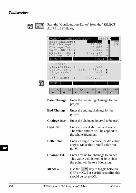
254 TPS-System 1000 Programs-2.3.1en © Leica
IV
EL
AH
OH
BS
SM
AS
FS
BL
HB
KM
FB
SA
PZ
LB
TB
CO
RP
Configuration
Start the "Configuration-Editor" from the "SELECTALN FILES" dialog.
ROAD+\ CONFIGURATION 14:03
MC
INFO DFLT EDIT
3D Stake : ONCrs.Intrpl. : OFFCrs.Movemnt : Left > RightHinge mode : normalLog File : ONLog FlName : ROAD.LOG
Base Chainge: Enter the beginning chainage for theproject
End Chainge : Enter the ending chainage for theproject
Chainge Incr : Enter the chainage interval to be used
Hght. Shift : Enter a vertical shift value if needed.The value entered will be applied tothe whole alignment.
Deflct. Tol. : Enter an angle tolerance for deflectionangles. Make this a small value butnot 0.
Chainge Tol. : Enter a value for chainage tolerance.This value will determine how closethe point will be to a 0 location.
3D Stake : Use the key to toggle betweenOFF or ON. For cut/fill capability thisshould be set to ON.
Base Chainge : 0.000End Chainge : 89.270Chainge Incr : 10.000 mHght. Shift : 0.000 mDeflct. Tol. : 0°00'16"Chainge Tol. : 0.010 m
F1 F2 F3 F4 F5 F6
HELP

© Leica TPS-System 1000 Programs-2.3.1en 255
IV
EL
AH
OH
BS
SM
AS
FS
BL
HB
KM
FB
SA
PZ
LB
TB
CO
RP
Crs. Intrpl. : The abbreviation means "CrossSection Interpolation". When this isset to ON, cross sections will beinterpolated both along and betweencross sections. The interpolationbetween cross sections makessuperelevation and widening possible.
If cross section interpolation is enabled, all crosssections must have the same number of points.
Use the key to toggle between
OFF and ON.
Crs. Movemnt: This function controls the movementalong the cross section.
Press to display the movement
options. There are three choices:LEFT to RIGHT, RIGHT to LEFTand NONE. The direction chosen isfor display purposes only. Therodperson can go in any directiondesired along the cross section.
Hinge Mode : Normal: The points farest away fromthe axis are used for calculation of theslope piercing point.Not from End Pts: The points farestaway from the axis are not used forcalculation of the slope piercing point,i.e. the slope piercing point is alreadyavailable in the cross sectiondefinition (catch point between digitalground pattern and cross section).

256 TPS-System 1000 Programs-2.3.1en © Leica
IV
EL
AH
OH
BS
SM
AS
FS
BL
HB
KM
FB
SA
PZ
LB
TB
CO
RP
ROAD+\ SELECT ALN FILES 14:03
MCHoriz. Aln.: ALN_EX1
Vert. Aln. : PRF_EX1Cross Secs : CRS_EX1Crs.Assign : STA_EX1Station Eq : EQN_EX1Log FlName : ROADPLUS.LOG
LIST
F1 F2 F3 F4 F5 F6
HELP CONF
Log file : When the log file is set to ON, stakedout data can be stored in a file for
printing at al later date. Use the
key to toggle between OFF and ON.
Log FlName : Ente a file name for the log file. Thedefault file name can be used.LogFlName appears only if "Log File= ON" is seledted in the"Configuration".
Displays date and version of the program.
Sets standard values. The values are displayed in dialogon page 253.
Accepts and stores parameters displayed. Continues todisplay "SELECT ALN FILES"
To proceed further, you must select a horizontalalignment file. The other files are optional and aredependent on what you are staking. For instance, if youare only staking the ”shape” of the road for clearingpurposes, then it would not be necessary to have avertical alignment, template, cross section assignmentor station equation file. If your application requiresthese other files then you will need to select them.
All alignment files must be stored in the memory cardin the GIS directory.
Select Alignment Files

© Leica TPS-System 1000 Programs-2.3.1en 257
IV
EL
AH
OH
BS
SM
AS
FS
BL
HB
KM
FB
SA
PZ
LB
TB
CO
RP
The horizontal alignment file contains the followingelements:
• Station locations• Straight line segments• Circular curves• Spiral curves• Compound curves• End of Project (EOP)
Select the horizontal alignment file. A dialog boxappears with a list of all ALN?????.GSI files available.Move the cursor to the file needed and press . The"SELECT ALN FILE" display will return and thecursor will be highlighting the vertical alignment file.
Horizontal AlignmentFile
The template file contains the following elements:• Station location• Template name• Offset from centerline• Difference in height from the
centerline profile
Select the cross section file. A dialog box appears witha list of all CRS?????.GSI files available. Move thecursor to the file needed and press . The "SELECTALN FILE" display will return and the cursor will behighlighting the Cross section assignment file.
Cross Section/templateFile
Vertical Alignment File The vertical alignment file contains the followingelements:
• Station locations• Straight line segments• Circular vertical curves• Parabolic vertical curves• End of Project (EOP)
Select the vertical alignment file. A dialog box appearswith a list of all PRF?????.GSI files available. Movethe cursor to the file needed and press . The"SELECT ALN FILE" display will return and thecursor will be highlighting the Cross Section file.

258 TPS-System 1000 Programs-2.3.1en © Leica
IV
EL
AH
OH
BS
SM
AS
FS
BL
HB
KM
FB
SA
PZ
LB
TB
CO
RP
Cross Section Definition
When defining the cross section both a cut and filltemplate can be created similar to the followingdiagrams.
Cross section - Cut
Cross section - Fill
RP
LU
S0
2
CL
Negative offset Positive offset
RP
LU
S0
1
CL
Negative offset Positive offset
CL ... Centerline
© Leica TPS-System 1000 Programs-2.3.1en 259
IV
EL
AH
OH
BS
SM
AS
FS
BL
HB
KM
FB
SA
PZ
LB
TB
CO
RP
The cross section assignment file contains the followingelements:
• Cross Section name• Starting Chainage
A cross section assigned in this manner will remain ineffect until another cross section is defined. When thefile is created you designate the name of the template touse and the chainage to begin using the template. Thenext template name entered also contains a startingchainage. A third template can be assigned to begin atanother chainage and so forth.
For example, the file might contain the followinginformation:
XSEC1, 0XSEC2, 100XSEC3, 300XSEC1, 550
The program would interpret this to use the templateXSEC1 beginning at chainage 0 and end at chainage1+00, use XSEC2 beginning at chainage 1+00 and endat chainage 3+00, use XSEC3 from chainage 3+00 andtransition back to XSEC1 ending at chainage 5+50.
Select the cross section assignment file. A dialog boxappears with a list of all STA?????.GSI files available.
Move the cursor to the file needed and press .
Cross Section AssignmentFile

260 TPS-System 1000 Programs-2.3.1en © Leica
IV
EL
AH
OH
BS
SM
AS
FS
BL
HB
KM
FB
SA
PZ
LB
TB
CO
RP
• Cross Section Interpolation
Cross sections can be interpolated both along the crosssection i.e. between defined points, and between crosssections themselves. The interpolation between crosssections makes superelevtion and widening possible.The following diagrams illustrate these concepts.
RP
LU
S0
4
CL
100
130
150
Cross Section AInterpolated CrossSection
3.50
3.00
RP
LU
S0
3
CL
CL offset
CL offset
Interpolated point Interpolated point(horizontal)
Last pointon Xsec
∆H
∆H
Interpolation along a cross section
Cross Section B(with widening)
Interpolation between cross sections

© Leica TPS-System 1000 Programs-2.3.1en 261
IV
EL
AH
OH
BS
SM
AS
FS
BL
HB
KM
FB
SA
PZ
LB
TB
CO
RP
• Superelevation/Widening
Superelevation is controlled by the cross sections.Cross sections must be placed at the appropriatechainage for the beginning of superelevation, fullsuperelevation and back to no superelevation.The STA?????.GSI file contains these special locationsfor cross sections as well as cross section locations forwidening. The diagram that follows illustrates theconcept for superelevation.
Superelvation governed by cross sections
5.5
6.0
6.5
7.0
A
B
C
D
Cross Section ANo Superelevation
Cross Section BIntermediate
Cross Section CIntermediate
CL
Cross Section DFull Superelevation
RP
LU
S0
5

262 TPS-System 1000 Programs-2.3.1en © Leica
IV
EL
AH
OH
BS
SM
AS
FS
BL
HB
KM
FB
SA
PZ
LB
TB
CO
RP
Station Equation File Station equations are used to adjust the alignmentstationing. The most common reason for doing so is theinsertion or removal of curves. Inserting or removing acurve would require re-calculating the stationing of anentire alignment. Using station equations eliminatesthis.
Station equations can create either a gap or overlap asshown in the following diagram.
Select the station equation file. A dialog box appearswith a list of all EQN?????.GSI files available. Move
the cursor to the file needed and press . The
"SELECT ALN FILE" display will return and thecursor will be highlighting the Log Filename. Thefilename can be changed or the default name can beaccepted.
When all files have been selected. Continues to display"CHAINAGE & OFFSET". Prior to the "CHAINAGE& OFFSET" display appearing, you will see a briefmessage about checking for errors in the selected files.
Forward Station EquationStation Back 10 + 000 = Station Ahead 15 + 000
1 2 3 4 5 6 7 8 9 1011 12 13 14 15
15 16 17 18 19 20 21 22 23
RP
LU
S0
6
1
3
2
4
89 10
5
6
7
56
7
8
9
10
1112 13 14 15
new
old
RP
LU
S1
6
1 2 3 4 5 6 7 8 9 10 11 12 13
1 2 3 4 5 6 7 8 9 10 11 12
Backward Station EquationStation Back 13 + 000 = Station Ahead 7 + 000
1
23
4
5
6
7
8
9 10 1112 13
2
3
4
5
67
new
old
RP
LU
S1
4R
PL
US
15

© Leica TPS-System 1000 Programs-2.3.1en 263
IV
EL
AH
OH
BS
SM
AS
FS
BL
HB
KM
FB
SA
PZ
LB
TB
CO
RP
File Checking During the file checking process, each file is inspectedfor possible errors in the data format such as missing orincorrect word index. If errors are found, an errormessage is displayed indicating the type of error.During the inspection process, if any errors are foundthat would cause erroneous data to be computed anddisplayed, the file checking routine will be aborted. Ifthis occurs, the file(s) containing the problem must befixed before continuing. In addition to checking for fileerrors, geometrical components are checked. Thisincludes tangent directions of adjacent elements andchord lengths of elements. Any deviations which exceedpermitted tolerances are displayed such as in thefollowing example.
ROAD+\ CHECKING FILES 14:03
MC
ALN: Deflection toleranceexceeded at chainage 1502.120.Difference in directionsis 0"02'31". Override?
NO YES
F1 F2 F3 F4 F5 F6
Selecting the "NO" option to override will bring upanother display that says "Continue checkingalignment"? (no quotes). If you choose "NO" thedisplay will return to the "SELECT ALN FILES" menu.If you choose "YES" the program will continue tocheck the other files. If no other errors are found theprogram will go to the opening "CHAINAGE &OFFSET" display.
Selecting the "YES" option to override will cause theprogram to override the error and continue to checkother files for possible errors. If no other errors arefound the program will go to the "CHAINAGE &OFFSET" opening display.

264 TPS-System 1000 Programs-2.3.1en © Leica
IV
EL
AH
OH
BS
SM
AS
FS
BL
HB
KM
FB
SA
PZ
LB
TB
CO
RP
Stakeout Using Horizon-tal Offset
The most common method for staking out roads,pavement, curb & gutter etc. is to use a horizontal offsetfrom the actual point. For instance, a four foot offsetfrom finished back of curb (BC) is commonly used toprovide cut/fill stakes for a street and curb lines.
Preparing for theexample
In this section of the manual, a sample project will beused to demonstrate the procedures to follow forstaking a portion of the job. The project consists of a3 m wide paved bicycle path with a curve. The projectwill be staked on a 0.6 m offset from the edge ofpavement. The POB and PC will be staked for bothsides.
The example project for the TPS System"ROADPLUS" program consists of a simple horizontaland vertical alignment accompanied by a simpletemplate. The project is designed to illustrate theapplication of the "ROADPLUS" System. It is notintended to provide a demonstration of road designprocedures.
N
3.0
30.0
Setup Point
RP
LU
S0
7
1.15
3.0
0.6

© Leica TPS-System 1000 Programs-2.3.1en 265
IV
EL
AH
OH
BS
SM
AS
FS
BL
HB
KM
FB
SA
PZ
LB
TB
CO
RP
Our bike path is about 30 m in length as illustrated here.The riding surface is 3 m wide, lying 1.5 m on each sideof the centerline. From the edge of the driving surface,fill slopes extend downward at a slope of 2:1.
The vertical alignment (or profile) for the project is asimple 2% uphill slope. An assumed elevation of 30.50is placed on the original ground at the Setup Point, andthe road starts at elevation 31.1. This allows you topractice with all of the components of the"ROADPLUS" program. For the field work, werecommend a flat, open area about 25 m on a side.
The following pages contain illustrations and listings ofall the data needed to run the example.
There are 3 easy steps to the example:
1. Use the "ROADDATA.EXE" program on yourPC to enter the design information for the Hori-zontal Alignment, Vertical Alignment, andTemplates.A special naming convention identifies the type offile that each alignment and template are stored in.The first three letters in the file name tell"ROADPLUS" what is in the file and how to view it.The GSI extension is also required.
Horizontal Alignment: ALN?????.GSIVertical Alignment: PRF?????.GSITemplates: CRS?????.GSI
In "ROADDATA.EXE", enter the following exampleproject data. Let’s call the project "EXAMPLE" andconfigure the units to m, 3 decimal places. Let’s namethe files "ALN_EX1.GSI", "PRF_EX1.GSI", and"CRS_EX1.GSI".

266 TPS-System 1000 Programs-2.3.1en © Leica
IV
EL
AH
OH
BS
SM
AS
FS
BL
HB
KM
FB
SA
PZ
LB
TB
CO
RP
Horizontal Alignment: ALN_EX1.GSI
Station Element Rad/Par Template E N
0.000 Straight 0.000 Tutor 305.000 305.0007.620 Curve 9.080 Tutor 305.000 312.620
20.298 Straight 0.000 Tutor 312.502 321.56227.918 EOP 0.000 Tutor 320.007 322.885
RP
LU
S0
9
2.000%
EOPCHA=0+27.918EOP EL=31.654
BOP CHA=0+00BOP EL=31.10
Road Profile at 2.00%
Original Ground of Elevation 30.500
RP
LU
S0
8
N
3 0 3 6 9 m
0+00
E: 314.15N: 308.05H: 30.50
0+6.10
PC CHA=0+7.62
E: 320.007N: 322.885Road Centerline
0+18.30
0+24.4
Edge of Road
E: 305.00N: 305.00H: 31.10
PT
CH
A=
0+20.298
Setup Point
Approx. Line of Catch Points
R = 9.080
E: 305.000N: 320.240
PICHA=0+15.240I=80°00'00"T=7.620R=9.087L=12.680C=11.674E=2.774M=2.125
T = 7.62
80°00'00"(88.889 gon)
L = 12.680
C = 11.674
T =
7.6
2
E = 2.774
M = 2.125

© Leica TPS-System 1000 Programs-2.3.1en 267
IV
EL
AH
OH
BS
SM
AS
FS
BL
HB
KM
FB
SA
PZ
LB
TB
CO
RP
Vertical Alignment : PRF_EX1.GSI
Chainage Element Rad/Par H
1 0 Straight 0 31.1002 27.918 EOP 0 31.654
Template: CRS_EX1.GSI
The horizontal alignment file specifies a template foreach chainage. Our horizontal alignment file specifiesonly one template, "TUTOR". You can, however,specify different templates for any chainage as you mayrequire. We will define two templates, "TUTOR" and"TYP_CUT", in our template file. Notice that whilerunning "ROADPLUS", you can switch templates atany time.
Template sCLO s ∆∆∆∆∆ H
1 Tutor -35.000 -16.7002 Tutor -1.500 -0.0303 Tutor 0.000 0.0004 Tutor 1.500 -0.0305 Tutor 35.000 -16.7006 TypCut -35.000 -16.6307 TypCut -1.500 -0.0308 TypCut 0.000 0.0009 TypCut 1.500 -0.03010 TypCut 35.000 -16.630
RP
LU
S1
0
CL
-1.5, -0.03 0, 0 1.5, -0.03
35, -16.7-35, -16.7
Slope extends well beyond expected Catch Point
Original Ground

268 TPS-System 1000 Programs-2.3.1en © Leica
IV
EL
AH
OH
BS
SM
AS
FS
BL
HB
KM
FB
SA
PZ
LB
TB
CO
RP
2. Copy the alignment and template files to yourPCMCIA card. Copy the files into the GSIsubdirectory on your PCMCIA card. If the GSIsubdirectory doesn’t already exist on the PCMCIAcard, you will need to create one. Place the PCMCIAcard in your instrument.
3. Set up the instrument in your work area andstakeout the example roadway. Set the instrumentcoordinates to the values shown for point 1 (seefigure page 264). Orient the instrument towards aconvenient "North", and set Hzo to zero (see figurepage 264). Start "ROADPLUS" and continue readingthis manual.
When the "CHAINAGE & OFFSET" display appears,only the lower portion beginning with "Station" will bevisible. To view the entire display, use the green up/down arrow keys on the keyboard to scroll up to thetop.
ROAD+\ CHAINAGE & OFFSET 14:03
MCHght. Shift : 0.000 m
Chainge Incr : 25.000Chainge : 0.000Element : POBOffset : 0.000 mHght Offset : 0.000 mCHECK CH--> <--CH XSEC EDIT
F1 F2 F3 F4 F5 F6
HELP STORE StaEq NOTE
Hght. Shift : Vertical shift applied to the wholealignment.
Chainge Incr : The chainage increment set in theconfiguration is displayed. If desired,a new value can be entered.
Chainage : Enter the chainage location for thepoints to be staked.

© Leica TPS-System 1000 Programs-2.3.1en 269
IV
EL
AH
OH
BS
SM
AS
FS
BL
HB
KM
FB
SA
PZ
LB
TB
CO
RP
Element : This displays the element for thechosen chainage such as POB, PC,CURVE etc.
Offset : Horizontal offset to apply to thecurrent chainage.
Hght Offset : Vertical offset to apply to the currentchainage.
Switches to measuring mode to allow for ameasurement to determine the chainage and offset forthe point shot. After taking the measurement, press
and the program will return to the "CHAINAGE& OFFSET" opening display. The chainage value ofwhere the shot was taken along with the horizontal andvertical offset are displayed.
Changes to the next chainage.
Changes to the previous chainage.
Activates the cross section options.
The result of the road chainage and offset is stored. Justactive after taking a measurement.
Activates the "Station Equation" option. Active only if a"Station Equation File" is selected during display"SELECT ALN FILES" (page 254).
Allows insertion of a note into a log file. This may beuse for comments, errors, etc.
Calls the dialog "POINT COORDS" in order to displaythe coordinates of the point to be set out. From there,calls the program "STAKEOUT".

270 TPS-System 1000 Programs-2.3.1en © Leica
IV
EL
AH
OH
BS
SM
AS
FS
BL
HB
KM
FB
SA
PZ
LB
TB
CO
RP
Select Template point andoffset
The first step in the procedure is to select a point on thecross section to be staked and enter the offset.
Access the cross section options.
ROAD+\ CROSS SECTIONS 14:03
MC1L
Chainage : 0.000Hght. Shift : 0.000 mTemplate : +000tutor∆CL Offset : -1.500 m∆CL Hgt Diff : -0.030 mCATCH <- CENTR ->
Stake Offs. : -0.600 mS.Offset Ht : HorizontalOffset : 0.000 mHght Offset : 0.000 m
F1 F2 F3 F4 F5 F6
HELP PLOT
1L : Indicates the location of the crosssection point in relation to thecenterline. In this example, the "1L"means the first point of the templateleft of centerline.
Chainage : Displays the current chainage.
Hght. Shift : Displays the vertical shift, if any,applied to the whole alignment.
Template : Displays the template name beingused.
∆CL Offset : Displays the horizontal distance of thetemplate point from centerline (- forleft)
∆CL Hgt Diff : Displays the difference in elevation ofthe template point between thecenterline and the point to be staked.

© Leica TPS-System 1000 Programs-2.3.1en 271
IV
EL
AH
OH
BS
SM
AS
FS
BL
HB
KM
FB
SA
PZ
LB
TB
CO
RP
Stake Offs. : This is the offset value that will beused for setting the offset stake. If thepoint is left of centerline, the valueentered must be a negative number.
S. Offset Ht : This display indicates the method usedin computing the elevation of the pointto be staked. The three methods are"PREVIOUS ELEMENT","INTERPOLATED" and"HORIZONTAL".
Offset : Horizontal offset to apply to currentchainage.
Hght Offset : Vertical offset to apply to currentchainage.
Activates the slope staking options
Move along the current cross section from right to left.
Sets the cross section point to the centerline
Move across the current cross section from left to right
Displays a plot of the template.
The first point we want to stake for the bike path is theleft edge of pavement. This point is 1.5 m left ofcenterline so the "∆CL Offset" value should be set toa -1.5 m.
Change the location to -1.5 m. The "∆CL Hght Diff"value will automatically change to the correct verticaldifference based upon the design of the template.

272 TPS-System 1000 Programs-2.3.1en © Leica
IV
EL
AH
OH
BS
SM
AS
FS
BL
HB
KM
FB
SA
PZ
LB
TB
CO
RP
The offset value needs to be set to a -0.600 m. Thenegative value is used because the point to stake is leftof centerline.
To accept the value press .
The final step in the process is to select the method touse for computing the elevation of the offset point to bestaked. The "ROADPLUS" program provides threemethods to choose from:
Horizontal - The elevation is computedhorizontally to the catch point.
Previous Element - The elevation is computed on anextension of the grade of theprevious element.
Interpolated - The elevation is interpolated tointersect the design slope of thecross section.
The following illustration shows the three verticaloptions for stake offset.
Cen
terli
ne
1
2
3
RP
LU
S11
1 Horizontal
2 Previous Element
3 Interpolated
Stake Offset

© Leica TPS-System 1000 Programs-2.3.1en 273
IV
EL
AH
OH
BS
SM
AS
FS
BL
HB
KM
FB
SA
PZ
LB
TB
CO
RP
The most common method used is the "HORIZON-TAL" method.To select this method, move the cursor to "S. Offset Ht"
and press to display the three options.
Move the cursor to "HORIZONTAL" and press .
This setting will remain as the current method until adifferent method is chosen. Therefore it is not necessaryto go through the procedure every time.
Accepts and stores parameters set. Continues to display"POINT COORDS".
Stakeout and Recordpoint
The "POINT COORDS" dialog displays the currentchainage location of the offset point to be staked. Thedisplay also shows the value for the prism pole (Refl.Height) and the Easting and Northing coordinates of theoffset point and the finished grade elevation of theactual point (not the offset location).
ROAD+\ POINT COORDS 14:03
MCChainage : 0.000
Refl.Height : 1.500 mEasting : 331.000 mNorthing : 335.000 mElevation : 31.000 m
STAKE EDIT
F1 F2 F3 F4 F5 F6
HELP
Activates the stakeout program

274 TPS-System 1000 Programs-2.3.1en © Leica
IV
EL
AH
OH
BS
SM
AS
FS
BL
HB
KM
FB
SA
PZ
LB
TB
CO
RP
STAKE\ POLAR STAKEOUT 14:03
MCTarget no. : 3
∆ Hz : 0°00'00"∆ Dist : 0.007 m∆ Height :FILL 1.320 mElevation : 32.700 m
ALL DIST REC TARGT αNUM
F1 F2 F3 F4 F5 F6
HELP METHD PLOT
The polar method of stakeout is the default for"ROADPLUS".Turn the instrument until "∆ Hz" is zero.Line up the prism pole.
Measure the distance.
The "∆ Dist" value indicates how far away themeasured point is from the point chosen to be staked. Apositive value means to move away from the instrumentby the amount shown. If the value is negative, movetowards the instrument. The display will also show thecut or fill value for the measured point. When both thehorizontal circle and distance read zero or close to it,the measurement can be recorded.
Record the staked out position, returns to the "CROSSSECTIONS" display and automatically moves to thenext point on the cross section.

© Leica TPS-System 1000 Programs-2.3.1en 275
IV
EL
AH
OH
BS
SM
AS
FS
BL
HB
KM
FB
SA
PZ
LB
TB
CO
RP
Stakeout Next point on Cross Section
ROAD+\ CROSS SECTIONS 14:03
MC1R
Chainage : 0.000Template : +000tutor∆CL Offset : 1.500 m∆CL Hgt Diff : -0.030 mStake Offs. : 0.600 mCATCH <- CENTR ->
F1 F2 F3 F4 F5 F6
HELP
To set the offset stake for the right side of our exampleproject:
Set the "∆CL Offset" value to positive 1.500 m.Note when you do this the position changes from "1L"to "1R". Scroll down and highlight "Stake Offs.".Change the offset value to positive 0.600 m.
Returns to the "POINT COORDS" display.
ROAD+\ POINT COORDS 14:03
MCChainage : 0.000
Refl.Height : 1.500 mEasting : 331.000 mNorthing : 335.000 mElevation : 31.000 m
STAKE EDIT
F1 F2 F3 F4 F5 F6
HELP
Stakeout the 0.600 m offset stake for the right side ofthe bike path. The "POLAR STAKEOUT" displayreturns.

276 TPS-System 1000 Programs-2.3.1en © Leica
IV
EL
AH
OH
BS
SM
AS
FS
BL
HB
KM
FB
SA
PZ
LB
TB
CO
RP
STAKE\ POLAR STAKEOUT 14:03
MCTarget no. : 4
∆ Hz : 0°00'00"∆ Dist : 0.007 m∆ Height :FILL 1.320 mElevation : 32.700 m
ALL DIST REC TARGT αNUM
F1 F2 F3 F4 F5 F6
HELP METHD PLOT
ROAD+\ CROSS SECTIONS 14:03
MC1R
Chainage : 0.000Template : +000tutor∆CL Offset : 1.500 m∆CL Hgt Diff : -0.030 mStake Offs. : 0.600 mCATCH <- CENTR ->
F1 F2 F3 F4 F5 F6
HELP
Measures the distance.
Record the point when it has been staked. The "CROSSSECTION" display returns showing the next point onthe cross section to stake.
For this example, the last point staked was the 0.600 moffset point for the right side. When the "CROSSSECTIONS" display appears, the "∆CL Offset" changesto the next point on the cross section. The next point tostake is the 0.600 m offset for the right side at the nextstation.
Exits from the "CROSS SECTIONS" display andreturns to the "CHAINAGE & OFFSET".

© Leica TPS-System 1000 Programs-2.3.1en 277
IV
EL
AH
OH
BS
SM
AS
FS
BL
HB
KM
FB
SA
PZ
LB
TB
CO
RP
ROAD+\ CHAINAGE & OFFSET 14:03
MCChainage : 0.000
Element : POBOffset : 0.000 mHght Offset : 0.000 m
CHECK CH--> <--CH XSEC EDIT
F1 F2 F3 F4 F5 F6
HELP
Moves to the next chainage (you also may enter achainage). The chainage and offset display will changeto reflect the new chainage location.
Brings up the "CROSS SECTIONS" display.
ROAD+\ CROSS SECTIONS 14:03
MC1R
Chainage : 25.000Template : +000tutor∆CL Offset : 1.500 m∆CL Hgt Diff : -0.030 mStake Offs. : 0.600 mCATCH <- CENTR ->
F1 F2 F3 F4 F5 F6
HELP
In our example the last point staked was on the rightside. Rather than have the rod person cross back over tothe left side, it makes sense to stay on the right side andstake that position and then cross over to the left side.To stake the catch point on the right side:
Set the "∆CL Offset" from centerline value to positive1.500 m. The offset value should be positive 0.600 m,but should not require a change because that was thelast offset value used for the previous right side point.
Access the "POINT COORDS" display.

278 TPS-System 1000 Programs-2.3.1en © Leica
IV
EL
AH
OH
BS
SM
AS
FS
BL
HB
KM
FB
SA
PZ
LB
TB
CO
RP
ROAD+\ POINT COORDS 14:03
MCChainage : 25.000
Refl.Height : 1.500 mEasting : 337.000 mNorthing : 340.500 mElevation : 31.200 m
STAKE EDIT
F1 F2 F3 F4 F5 F6
HELP
To stake the offset point on the right side for chainage25+00:
Activates the stakeout program. The "POLARSTAKEOUT" display will appear.
STAKE\ POLAR STAKEOUT 14:03
MCTarget no. : 5
∆ Hz : 0°00'00"∆ Dist : 0.010 m∆ Height :FILL 0.950 mElevation : 33.187 m
ALL DIST REC TARGT αNUM
F1 F2 F3 F4 F5 F6
HELP METHD PLOT
Use the normal procedure previously outlined forstaking out the point.
Records the staked out position and returns to the"CROSS SECTIONS" display.

© Leica TPS-System 1000 Programs-2.3.1en 279
IV
EL
AH
OH
BS
SM
AS
FS
BL
HB
KM
FB
SA
PZ
LB
TB
CO
RP
ROAD+\ CROSS SECTIONS 14:03
MC1L
Chainage : 25.000Template : +000tutor∆CL Offset : -1.500 m∆CL Hgt Diff : -0.030 mStake Offs. : -0.600 mCATCH <- CENTR ->
F1 F2 F3 F4 F5 F6
HELP
Change the "∆CL Offset" from centerline to negative1.5 m. Change the "Stake Offs." value to negative0.600 m.
Access the "POINT COORDS" display.
Access the stakeout program. Follow the stakeoutprocedure previously outlined and record the staked outpoint. When the "CROSS SECTIONS" display returns,press to access the "CHAINAGE & OFFSET"display.
ROAD+\ POINT COORDS 14:03
MCChainage : 25.000
Refl.Height : 1.500 mEasting : 331.000 mNorthing : 340.500 mElevation : 31.200 m
STAKE EDIT
F1 F2 F3 F4 F5 F6
HELP
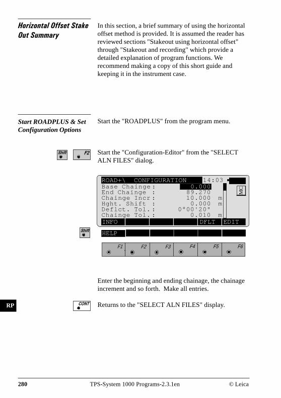
280 TPS-System 1000 Programs-2.3.1en © Leica
IV
EL
AH
OH
BS
SM
AS
FS
BL
HB
KM
FB
SA
PZ
LB
TB
CO
RP
Horizontal Offset StakeOut Summary
In this section, a brief summary of using the horizontaloffset method is provided. It is assumed the reader hasreviewed sections "Stakeout using horizontal offset"through "Stakeout and recording" which provide adetailed explanation of program functions. Werecommend making a copy of this short guide andkeeping it in the instrument case.
Start ROADPLUS & SetConfiguration Options
Start the "ROADPLUS" from the program menu.
Start the "Configuration-Editor" from the "SELECTALN FILES" dialog.
ROAD+\ CONFIGURATION 14:03
MC
INFO DFLT EDIT
Base Chainge : 0.000End Chainge : 89.270Chainge Incr : 10.000 mHght. Shift : 0.000 mDeflct. Tol. : 0°00'20"Chainge Tol. : 0.010 m
F1 F2 F3 F4 F5 F6
HELP
Enter the beginning and ending chainage, the chainageincrement and so forth. Make all entries.
Returns to the "SELECT ALN FILES" display.

© Leica TPS-System 1000 Programs-2.3.1en 281
IV
EL
AH
OH
BS
SM
AS
FS
BL
HB
KM
FB
SA
PZ
LB
TB
CO
RP
Select Alignment Files
ROAD+\ SELECT ALN FILES 14:03
MCHoriz. Aln. : ALN_EX1
Vert. Aln. : PRF_EX1Cross Secs : CRS_EX1Crs.Assign : STA_EX1Station Eq : EQN_EX1Log FlName : ROADPLUS.LOG
LIST
F1 F2 F3 F4 F5 F6
HELP CONF
Select the alignment files.
Place the cursor on each file type, press and pick
the file from the displayed list. Select the files.
The "CHAINAGE & OFFSET" options are displayed.
A horizontal file must be selected.

282 TPS-System 1000 Programs-2.3.1en © Leica
IV
EL
AH
OH
BS
SM
AS
FS
BL
HB
KM
FB
SA
PZ
LB
TB
CO
RP
Set offset value and selectpoint to stakeout
ROAD+\ CHAINAGE & OFFSET 14:03
MCChainage : 0.000
Element : POBOffset : 0.000 mHght Offset : 0.000 m
CHECK CH--> <--CH XSEC EDIT
F1 F2 F3 F4 F5 F6
HELP
To select the template point to stake (back of curb, edgeof pavement etc.):
The "CROSS SECTIONS" options display appears.
ROAD+\ CROSS SECTIONS 14:03
MC1R
Chainage : 25.000Template : +000tutor∆CL Offset : 1.500 m∆CL Hgt Diff : -0.030 mStake Offs. : 0.600 mCATCH <- CENTR ->
F1 F2 F3 F4 F5 F6
HELP
Set the "∆CL Offset" value. This value is the distancefrom centerline of the point you want to stake.Move the cursor to "Template" and pick the crosssection template to use. Following set the "Stake Offs."(stake offset value). If the point is left of the centerline,enter the offset value as a negative value.
Continues with display "POINT COORDS".
or

© Leica TPS-System 1000 Programs-2.3.1en 283
IV
EL
AH
OH
BS
SM
AS
FS
BL
HB
KM
FB
SA
PZ
LB
TB
CO
RP
Stakeout the point ROAD+\ POINT COORDS 14:03
MCChainage : 0.000
Refl.Height : 1.500 mEasting : 331.000 mNorthing : 335.000 mElevation : 31.000 m
STAKE EDIT
F1 F2 F3 F4 F5 F6
HELP
The stakeout program will start with the polar stakeoutmethod being used.
STAKE\ POLAR STAKEOUT 14:03
MCTarget no. : 4
∆ Hz : 0°00'00"∆ Dist : 0.007 m∆ Height :FILL 1.320 mElevation : 32.700 m
ALL DIST REC TARGT αNUM
F1 F2 F3 F4 F5 F6
HELP METHD PLOT
With the polar method, the theodolite is turned until thedisplayed horizontal circle reading is zero degrees. Therod person is moved on line and a distance is measured.The results are displayed telling you how far from thereal point the prism pole is. Move the rodperson untilthe distance shows near zero. The CUT/FILL value isdisplayed along with the elevation of the point.
Record the point, and the "CROSS SECTIONS" displayreturns.
Move to a new chainage. The "CHAINAGE & OFF-SET" display returns.

284 TPS-System 1000 Programs-2.3.1en © Leica
IV
EL
AH
OH
BS
SM
AS
FS
BL
HB
KM
FB
SA
PZ
LB
TB
CO
RP
Select new chainage
ROAD+\ CHAINAGE & OFFSET 14:03
MCChainage : 0.000
Element : POBOffset : 0.000 mHght Offset : 0.000 m
CHECK CH--> <--CH XSEC EDIT
F1 F2 F3 F4 F5 F6
HELP
Select a new chainage (you also may enter a chainage).
Select the point to stake out and the offset.Repeat the procedure outlined in sections "Set offsetvalue and select point to stakeout" (page 282) through"Select new chainage" (page 284). Continue in thismanner until all points have been staked.

© Leica TPS-System 1000 Programs-2.3.1en 285
IV
EL
AH
OH
BS
SM
AS
FS
BL
HB
KM
FB
SA
PZ
LB
TB
CO
RP
Slope Staking Slope staking involves determining a point where thecross section template meets the ground surface. Thispoint of zero cut/fill is found primarily by trial and errorand a lot of computing. The following diagramillustrates the concepts of slope staking.
The slope staking routine is accessed from the "CROSSSECTIONS" display.
Cen
terli
neC
ente
rline R
PL
US
12
CL Offset
CL Offset
Catch Point
CrossSection
CrossSection
FILL
Catch Point
CUT
Plan View
Plan View0+200.000
0+200.000
∆Chainage
∆Chainage
∆XS Hgt Diff
∆XS Hgt Diff

286 TPS-System 1000 Programs-2.3.1en © Leica
IV
EL
AH
OH
BS
SM
AS
FS
BL
HB
KM
FB
SA
PZ
LB
TB
CO
RP
Start the "CROSS SECTIONS" display from the"CHAINAGE & OFFSET" display.
ROAD+\ CROSS SECTIONS 14:03
MC1L
Chainage : 0.000Hght. Shift : 0.000 mTemplate : +000tutor∆CL Offset : -1.500 m∆CL Hgt Diff : -0.030 mCATCH <- CENTR ->
F1 F2 F3 F4 F5 F6
HELP PLOT
Before proceeding, move the cursor to the "Template"option.
Choose the template to use for slope staking. If thedisplayed template is the correct one, then it will not benecessary to change it.
Start the slope stake program.
ROAD+\ SLOPE STAKING 14:03
MCChainage : 0.000
Template : typcutXsection : CUT∆CL Offset : 9.867 m∆XS Hgt Diff : 1.089 m∆Chainage : 3.254 m ALL DIST REC TARGT
F1 F2 F3 F4 F5 F6
HELP ∆St=0 STORE I<>II REFPT
The "STORE" and "REFPT" options are notavailable until after a measurement is taken.

© Leica TPS-System 1000 Programs-2.3.1en 287
IV
EL
AH
OH
BS
SM
AS
FS
BL
HB
KM
FB
SA
PZ
LB
TB
CO
RP
Measure to the current position of the prism pole.The value for "∆XS Hgt Diff" needs to be zero or closeto it. When this value is zero the catch point has beendetermined. However, the value for "∆Chainage" is alsoimportant. This value shows where the actual point is inrelation to the chainage of the cross section being used.
In the sample display shown, the value for "∆XS HgtDiff" is 1.089 m. The value is positive which means thecatch point is higher than where the measurement wastaken. Therefore the rodperson would look for a spotthat is approximately 1 m higher than the current point.
Now look at the value for "∆Chainage". This indicateswhere the prism pole is in relation to the chainage. Inthis example, the rodperson would move approximately3 m to his/her right looking towards the instrument. Ifthe value is negative the pole would be moved to theleft.
In addition, the horizontal distance from centerline isdisplayed which is 9.867 m for this example.
After moving to a new location, measure a distance tothe prism and view the results. When the "∆XS HgtDiff" and "∆Station" are at or near zero the catch pointhas been located both vertically and horizontally for thechosen chainage.
Record the staked out position.The "SLOPE STAKING" display returns and anothercatch point can be staked.
Exit the slope staking program.
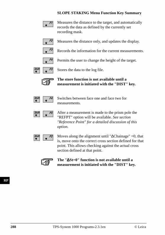
288 TPS-System 1000 Programs-2.3.1en © Leica
IV
EL
AH
OH
BS
SM
AS
FS
BL
HB
KM
FB
SA
PZ
LB
TB
CO
RP
SLOPE STAKING Menu Function Key Summary
Measures the distance to the target, and automaticallyrecords the data as defined by the currently setrecording mask.
Measures the distance only, and updates the display.
Records the information for the current measurements.
Permits the user to change the height of the target.
Stores the data to the log file.
The store function is not available until ameasurement is initiated with the "DIST" key.
Switches between face one and face two formeasurements.
After a measurement is made to the prism pole the"REFPT" option will be available. See section"Reference Point" for a detailed discussion of thisoption.
Moves along the alignment until "∆Chainage" =0, thatis, move onto the correct cross section defined for thatpoint. This allows checking against the actual crosssection defined at that point.
The "∆∆∆∆∆St=0" function is not available until ameasurement is initiated with the "DIST" key.

© Leica TPS-System 1000 Programs-2.3.1en 289
IV
EL
AH
OH
BS
SM
AS
FS
BL
HB
KM
FB
SA
PZ
LB
TB
CO
RP
Reference Point
Displays additional information about how the locationof the prism pole relates to components of the cross-section. Do this after a measurement has been made.
ROAD+\ REFERENCE POINT 14:03
MC1L
Chainage : 0.000Template : typcut∆Chainage : 3.254 m∆Catch Offs : -0.347 m∆Catch HgtD : -0.389 m ALL DIST REC TARGT
∆Hinge Offs : 8.154 m∆Hinge HgtD : -2.123 m∆CL Offset : 9.213 m∆CL HgtDiff : -1.124 m
F1 F2 F3 F4 F5 F6
HELP STORE I<>II
1L : Indicates the location of the crosssection point in relation to thecenterline. In this example, the "1L"means the first point of the templateleft of centerline.
Chainage : Displays the current chainage.
Template : Displays the template name beingused.
∆∆∆∆∆Chainage : Displays where the rod is in relation tothe actual chainage. Move the rod tothe right as you are looking from thepole towards the instrument if thevalue is positive. If the value isnegative move to the left.

290 TPS-System 1000 Programs-2.3.1en © Leica
IV
EL
AH
OH
BS
SM
AS
FS
BL
HB
KM
FB
SA
PZ
LB
TB
CO
RP
∆∆∆∆∆Catch Offs : This value is where the pole is inrelation to where the existing groundintersects the design slope of thetemplate.
∆∆∆∆∆Catch HgtD : This value is the vertical differencefrom the ground shot to where theexisting ground catches the template.
∆∆∆∆∆Hinge Offs : This is the horizontal distance fromthe prism to where the template beginsthe slope (hinges).
∆∆∆∆∆Hinge HgtD : The vertical difference between theground shot and the hinge point.
∆∆∆∆∆CL Offset : The horizontal distance from theground shot to the centerline.
∆∆∆∆∆CL HgtDiff : The vertical distance from the groundshot to the centerline.
The following illustration represents the variouscomponents of the REFPT option.
Cen
terli
ne
∆CL Offset
∆Hinge Offs
∆Catch Offs
RP
LU
S1
3
∆C
L H
gtD
iff
∆Hin
ge
Hg
tD
∆Ca
tch
Hg
tD

© Leica TPS-System 1000 Programs-2.3.1en 291
IV
EL
AH
OH
BS
SM
AS
FS
BL
HB
KM
FB
SA
PZ
LB
TB
CO
RP
Data Formats The following describes the format and contents of thedata stored for alignments and cross-sections in theRoadPlus program. All files are in GSI format and mustbe located in the \GSI directory of the memory card.
The following geometric elements are supported:Horizontal Alignment
Element Definition Declaration in thealignment file
Tangent Coordinates (X,Y) to Coordinates (X,Y) "STRAIGHT"
Circular curve Beginning of arc (X,Y), Radius, "000CURVE"End of arc (X,Y);
Spiral In Beginning of curve (X,Y), A-Parameter / "00SPIRIN"Length of curve + Radius,End of curve (X,Y);
Spiral out Beginning of curve (X,Y), A-Parameter / "0SPIROUT"Length of curve + Radius,End of curve (X,Y);
Compound Beginning of curve (X, Y), Radius 1, "0CURVEIN"curve in Radius 2
Compound Beginning of curve (X, Y), Radius 1, "CURVEOUT"curve out Radius 2
End of Project Coordinates (X,Y) "00000EOP"
Header of the Horizontal Alignment File:
41....+000JOBID 42....+HZALIGNM 43......+STACOORD
WI 41 Job-Identification. Max. 8 ASCII-characters,may be defined by user.
WI 42 Identification of Horizontal Alignment file.May not be changed by user.
WI 43 Identification of principal point type file. Maynot be changed by user.
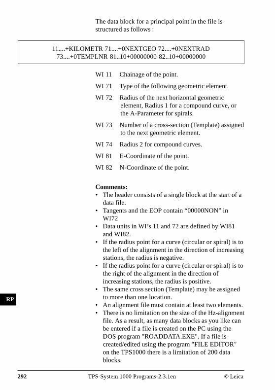
292 TPS-System 1000 Programs-2.3.1en © Leica
IV
EL
AH
OH
BS
SM
AS
FS
BL
HB
KM
FB
SA
PZ
LB
TB
CO
RP
The data block for a principal point in the file isstructured as follows :
11....+KILOMETR 71....+0NEXTGEO 72....+0NEXTRAD73....+0TEMPLNR 81..10+00000000 82..10+00000000
WI 11 Chainage of the point.
WI 71 Type of the following geometric element.
WI 72 Radius of the next horizontal geometricelement, Radius 1 for a compound curve, orthe A-Parameter for spirals.
WI 73 Number of a cross-section (Template) assignedto the next geometric element.
WI 74 Radius 2 for compound curves.
WI 81 E-Coordinate of the point.
WI 82 N-Coordinate of the point.
Comments:• The header consists of a single block at the start of a
data file.• Tangents and the EOP contain “00000NON” in
WI72• Data units in WI’s 11 and 72 are defined by WI81
and WI82.• If the radius point for a curve (circular or spiral) is to
the left of the alignment in the direction of increasingstations, the radius is negative.
• If the radius point for a curve (circular or spiral) is tothe right of the alignment in the direction ofincreasing stations, the radius is positive.
• The same cross section (Template) may be assignedto more than one location.
• An alignment file must contain at least two elements.• There is no limitation on the size of the Hz-alignment
file. As a result, as many data blocks as you like canbe entered if a file is created on the PC using theDOS program "ROADDATA.EXE". If a file iscreated/edited using the program "FILE EDITOR"on the TPS1000 there is a limitation of 200 datablocks.

© Leica TPS-System 1000 Programs-2.3.1en 293
IV
EL
AH
OH
BS
SM
AS
FS
BL
HB
KM
FB
SA
PZ
LB
TB
CO
RP
Example of a Horizontal Alignment:
41....+0EXAMPLE 42....+HZALIGNM 43....+STACOORD11....+00000000 71....+STRAIGHT 72....+00000NON73....+QP000125 81..10+06000000 82..10+0200000011....+00198832 71....+00SPIRIN 72....-0012247473....+QP000123 81..10+06068005 82..10+0218684111....+00348832 71....+000CURVE 72....-0010000073....+QP000123 81..10+06150344 82..10+0230775111....+00450725 71....+0SPIROUT 72....-0010000073....+QP000123 81..10+06247816 82..10+0230407111....+00550725 71....+STRAIGHT 72....+00000NON73....+QP000125 81..10+06310759 82..10+0222779411....+00714138 71....+00SPIRIN 72....+0005477273....+QP000124 81..10+06392465 82..10+0208627511....+00789138 71....+000CURVE 72....+0004000073....+QP000124 81..10+06445859 82..10+0203780711....+00824376 71....+0SPIROUT 72....+0004472173....+QP000124 81..10+06478120 82..10+0204888611....+00874376 71....+STRAIGHT 72....+00000NON73....+QP000125 81..10+06496445 82..10+0209447811....+01127904 71....+00000EOP 72....+00000NON73....+QP000125 81..10+06540469 82..10+02344154
The principal points method allows joining elementswithout the use of intermediate tangents.The following combinations, for example, may bedefined:
• Double spiral: spiral out followed by spiral in• Multiple circular curves• S curves with and without intermediate tangents

294 TPS-System 1000 Programs-2.3.1en © Leica
IV
EL
AH
OH
BS
SM
AS
FS
BL
HB
KM
FB
SA
PZ
LB
TB
CO
RP
Vertical Alignment Geometric elements supported:
Element Definition Declaration in theAlignment file
Tangent Coordinate (Km,H) to Coordinate (Km,H) "STRAIGHT"
Circular curve beginning of curve(Km,H), Radius, "000CURVE"end of curve (Km,H);
Parabola Coordinate (Km,H), Parabola parameter / "0PARABOL"Parabola length;
End of project Coordinate (Km,H) "00000EOP"
Vertical Alignment File Header:
41....+000JOBID 42....+0VALIGNM 43......+STACOORD
WI 41 Job-Identification. Max. 8 ASCII-characters,may be defined by user.
WI 42 Identification of Vertical Alignment file. Maynot be changed by user.
WI 43 Identification of principal point type file. Maynot be changed by user.
Example for a data block for a vertical alignmentpoint:
11....+KILOMETR 71....+0NEXTGEO 72....+0NEXTRAD 83..10+00000000
WI 11 Chainage of a vertical alignment point
WI71 Type of the following geometric element
WI72 Radius of the following geometric element orparabola parameter
WI83 Elevation of the point

© Leica TPS-System 1000 Programs-2.3.1en 295
IV
EL
AH
OH
BS
SM
AS
FS
BL
HB
KM
FB
SA
PZ
LB
TB
CO
RP
Comments:• The header consists of a single block at the start of a
data file.
• Tangents and the EOP contain “00000NON” inWI72
• Data units in WI’s 11, and 72 are defined by WI83.
• Tangent and arc lengths may be calculated from thestationing.
• The stationing is projected onto a horizontal plane.
• If the curve radius point lies above the centerline, theradius is positive.
• If the curve radius lies beneath the centerline, theradius is negative.
• An alignment file must contain at least two elements.
• There is no limitation on the size of the V-alignmentfile. As a result, as many data blocks as you like canbe entered if a file is created on the PC using theDOS program "ROADDATA.EXE". If a file iscreated/edited using the program "FILE EDITOR"on the TPS1000 there is a limitation of 200 datablocks.
Example of a vertical alignment file:
41....+0EXAMPLE 42....+0VALIGNM 43....+STACOORD11....+00000000 71....+STRAIGHT 72....+00000NON83..10+0040000011....+00300000 71....+0PARABOL 72....-0114293283..10+0042250011....+00500000 71....+STRAIGHT 72....+00000NON83..10+0042000011....+00550000 71....+0PARABOL 72....+0209112683..10+0041500011....+00850000 71....+STRAIGHT 72....+00000NON83..10+0040652211....+01127904 71....+00000EOP 72....+00000NON83..10+00418605

296 TPS-System 1000 Programs-2.3.1en © Leica
IV
EL
AH
OH
BS
SM
AS
FS
BL
HB
KM
FB
SA
PZ
LB
TB
CO
RP
Cross Sections Geometric elements supported:
Header of the cross section file:
41....+00JOB_ID 42....+TEMPLATE
WI41 Job identification. Max. 8 ASCII characters,user definable.
WI42 Template file identification. May not bechanged by user.
A data block for a cross section is structured asfollows:
11....+ PROF_NR 35....+DISTANCE 36....+000HDIFF
WI 11 The cross section number.
WI 35 Horizontal distance from the centerline.
WI 36 Height difference from the centerline.
WI 71 Cross section type.
WI 72 Slope ratio.
Element Definition
Height differences Height difference to the centerline
Distance Distance from the centerline
Cross section type Differentiate between CUT andFILL cross sections
Slope slope ratio
Comments:• The header consists of a single block at the start of a
data file.• All data blocks having the same cross section
number (WI11) belong together.• All data blocks belonging to a cross section must be
consecutive in the file to minimize file access.• The data blocks for a cross section must be sorted by
ascending distance from the centerline.

© Leica TPS-System 1000 Programs-2.3.1en 297
IV
EL
AH
OH
BS
SM
AS
FS
BL
HB
KM
FB
SA
PZ
LB
TB
CO
RP
• Cross-sections do not have to be sorted by number.• A negative distance (WI35) indicates a point to the
left of the centerline.• A positive distance (WI35) indicates a point to the
right of the centerline.• A negative height difference (WI36) indicates a point
below the centerline.• A positive height difference (WI36) indicates a point
above the centerline.• For a cross section file there is a limitation of 200
data blocks. The maximum number of points in across section is 48.
• A template file must contain at least one cross-section.• The entries for cross section type and slope are
optional.• The slope entry must be attached to the last point on
either side of the cross section.
Example:41....+0EXAMPLE 42....+TEMPLATE11....+QP000123 35..10-00013000 36..10-0000300011....+QP000123 35..10-00010000 36..10-0000500011....+QP000123 35..10-00004000 36..10-0000010011....+QP000123 35..10+00004000 36..10+0000010011....+QP000123 35..10+00010000 36..10-0000600011....+QP000123 35..10+00013000 36..10-0000350011....+QP000124 35..10-00012000 36..10-0000200011....+QP000124 35..10-00011000 36..10-0000400011....+QP000124 35..10-00004000 36..10+0000010011....+QP000124 35..10+00004000 36..10-0000010011....+QP000124 35..10+00011000 36..10-0000500011....+QP000124 35..10+00012000 36..10-0000250011....+QP000125 35..10-00012000 36..10-0000200011....+QP000125 35..10-00011000 36..10-0000250011....+QP000125 35..10-00004000 36..10-0000007011....+QP000125 35..10+00004000 36..10-0000007011....+QP000125 35..10+00011000 36..10-0000250011....+QP000125 35..10+00012000 36..10-0000200011....+TEMPLATE 35..41-00002000 36..11+0000000071....+0000FILL 72....+0000200011....+TEMPLATE 35..41-00000500 36..11+0000000071....+0000FILL 72....+0000000011....+TEMPLATE 35..41+00000000 36..11+0000000071....+0000FILL 72....+0000000011....+TEMPLATE 35..41+00001000 36..11+0000000071....+0000FILL 72....+0000000011....+TEMPLATE 35..41+00002000 36..11+0000000071....+0000FILL 72....+00002000
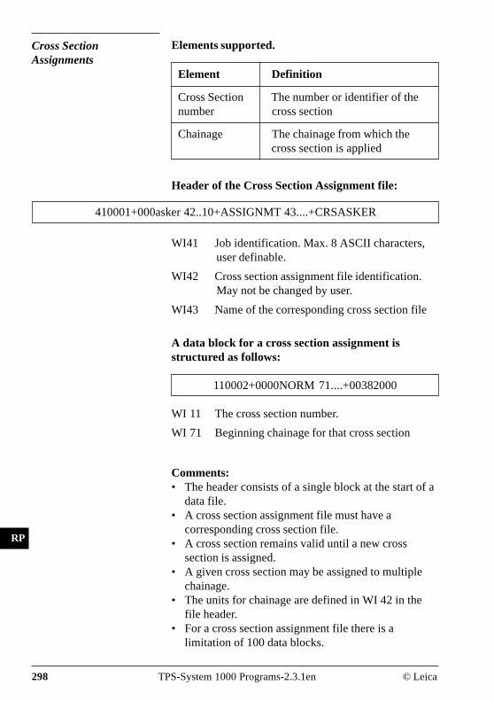
298 TPS-System 1000 Programs-2.3.1en © Leica
IV
EL
AH
OH
BS
SM
AS
FS
BL
HB
KM
FB
SA
PZ
LB
TB
CO
RP
Cross SectionAssignments
Elements supported.
WI41 Job identification. Max. 8 ASCII characters,user definable.
WI42 Cross section assignment file identification.May not be changed by user.
WI43 Name of the corresponding cross section file
A data block for a cross section assignment isstructured as follows:
110002+0000NORM 71....+00382000
WI 11 The cross section number.
WI 71 Beginning chainage for that cross section
Comments:• The header consists of a single block at the start of a
data file.• A cross section assignment file must have a
corresponding cross section file.• A cross section remains valid until a new cross
section is assigned.• A given cross section may be assigned to multiple
chainage.• The units for chainage are defined in WI 42 in the
file header.• For a cross section assignment file there is a
limitation of 100 data blocks.
Element Definition
Cross Section The number or identifier of thenumber cross section
Chainage The chainage from which thecross section is applied
Header of the Cross Section Assignment file:
410001+000asker 42..10+ASSIGNMT 43....+CRSASKER

© Leica TPS-System 1000 Programs-2.3.1en 299
IV
EL
AH
OH
BS
SM
AS
FS
BL
HB
KM
FB
SA
PZ
LB
TB
CO
RP
Example:
410001+000asker 42..10+ASSIGNMT 43....+CRSASKER110002+0000NORM 71....+00382000110003+0000NORM 71....+00552000110004+00000568 71....+00568000110005+000568.1 71....+00568100110006+000585.1 71....+00585100110007+000585.2 71....+00585200110008+0000NORM 71....+00611000110009+0000NORM 71....+00775000110010+00000811 71....+00811000110011+000826.9 71....+00826900110012+00000827 71....+00827000110013+00000827 71....+00844000110014+000826.9 71....+00844100110015+00000860 71....+00860000

300 TPS-System 1000 Programs-2.3.1en © Leica
IV
EL
AH
OH
BS
SM
AS
FS
BL
HB
KM
FB
SA
PZ
LB
TB
CO
RP
Station Equations Elements supported
Element Definition
Station equation The number or identifier of thenumber station equation
Chainage ahead The chainage to be applied goingforward along the alignment
Chainage back The chainage to be applied goingbackward along the alignment
Header of the Station Equation file :
41....+00JOB_ID 42....+0STAEQTN
WI41 Job identification. Max. 8 ASCII characters,user definable.
WI42 Station Equation file identification. May notbe changed by user.
A data block for a station equation is structured asfollows:
41....+00000001 42....+00100000 43....+00200000
WI 41 The station equation number.
WI 42 Chainage ahead.
WI 43 Chainage back.
Comments:• The header consists of a single block at the start of a
data file.• For a station equation file there is a limitation of 100
data blocks.
Example:
41....+00JOB_ID 42....+0STAEQTN41....+00000001 42..10+00100000 43..10+0020000041....+00000002 42..10+00566000 43..10+00600000

© Leica TPS-System 1000 Programs-2.3.1en 301
IV
EL
AH
OH
BS
SM
AS
FS
BL
HB
KM
FB
SA
PZ
LB
TB
CO
RP
Log File If "Log File" is set to "ON" the measurements and theresults are stored in the ASCII-file specified within the"Configuration Editor". This file is created in thedirectory LOG on the memory card. Subsequently, youcan read the memory card on your PC and obtain a hardcopy of the Log-file.
Data will always be appended to the specified Log-file.
The Log-file contains the following information:
Header includes:- the program used,- information about the instrument,- the file to store the measurementdata,
- the date and the time.
Configuration the name of the input files for:- the Hz-alignment,- the V-alignment and- the cross section.
Measurement - Instrument station with coordinatesand instrument height.
- Stakeout point with heigth offset,- offset1 and height displacement2
relative to centre line,- comparison values from planning,and associated differences.
1 This value results from- the displacement of the zero point of the profile and- the displacement taken from the transverse profile.
2 This value results from- the displacement of the zero point of the profile and- the displacement taken from the transverse profile- the height displacement in the configuration.
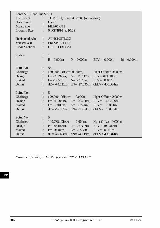
302 TPS-System 1000 Programs-2.3.1en © Leica
IV
EL
AH
OH
BS
SM
AS
FS
BL
HB
KM
FB
SA
PZ
LB
TB
CO
RP
Leica VIP RoadPlus V2.11Instrument : TCM1100, Serial 412784, (not named)User Templ. : User 1Meas. File : FILE01.GSIProgram Start : 04/08/1995 at 10:23
Horizontal Aln : ALNSPORT.GSIVertical Aln : PRFSPORT.GSICross Sections : CRSSPORT.GSI
Station : 1E= 0.000m N= 0.000m ELV= 0.000m hi= 0.000m
Point No. : 55Chainage : 150.000, Offset= 0.000m, Hght Offset= 0.000mDesign : E= -79.269m, N= 19.917m, ELV= 400.501mStaked : E= -1.057m, N= 2.578m, ELV= 0.107mDeltas : dE= -78.211m, dN= 17.339m, dELV= 400.394m
Point No. : 5Chainage : 100.000, Offset= 0.000m, Hght Offset= 0.000mDesign : E= -46.305m, N= 26.708m, ELV= 400.409mStaked : E= -0.000m, N= 2.774m, ELV= 0.051mDeltas : dE= -46.305m, dN= 23.934m, dELV= 400.358m
Point No. : 5Chainage : 100.785, Offset= 0.000m, Hght Offset= 0.000mDesign : E= -46.688m, N= 27.392m, ELV= 400.365mStaked : E= -0.000m, N= 2.774m, ELV= 0.051mDeltas : dE= -46.688m, dN= 24.619m, dELV= 400.314m
Example of a log file for the program "ROAD PLUS"

© Leica TPS-System 1000 Programs-2.3.1en 303
IV
EL
AH
OH
BS
SM
AS
FS
BL
HB
KM
FB
SA
PZ
LB
TB
CO
RP
FE
File Editor
Introduction The manual describes the program "FILE EDITOR(GSI)" of the LEICA TPS SYSTEM 1000 theodoliteseries. This version of the file editor is only valid for aGSI configuration.This program is used to open/to view and edit existingproject files for the program "RoadPlus" or for creationof new project files.In order to create new project files, the file names mustcomply with certain rules.
1. Horizontal Alignment FileFile Name: ALN?????.GSI
2. Vertical Alignment FileFile Name: PRF?????.GSI
3. Template FileFile Name: CRS?????.GSI
4. Station Equation FileFile Name: EQN?????.GSI
5. Cross-section Assignment FileFile Name: STA?????.GSI
You can insert a permitted character for a DOS filename in place of a ?.
Type of file Limitations
Horizontal alignment 200 data blocks
Vertical alignment 200 data blocks
Cross section 200 data blocks(number of points in a crosssection max. 48)
Cross section assignment100 data blocks
Station equation 100 data blocks
The following table shows an overview of the max. filesizes:
Creation of files
304 TPS-System 1000 Programs-2.3.1en © Leica
IV
EL
AH
OH
BS
SM
AS
FS
BL
HB
KM
FB
SA
PZ
LB
TB
CO
RP
FE
Editing files It is possible to insert also a new data set:
• With function "Coordinate", point coordinates,station coordinates or a code block can be inserted.
• With function "Horizontal Alignment " a tangent, acircular curve, a Spiral in, a Spiral out, a Curve in ora Curve out can be inserted.For the circular curve radius the following sign ruleapplies:With a right-hand curve (centre of circle right ofalignment) the sign is positive.With a left-hand curve (centre of circle left ofalignment) the sign is negative.
• With function "Vertical Alignment " a tangent, acircular curve or a parabola can be inserted.For the circular curve radius and/or the parabolaparameter the following sign rule applies:
If the centre of circle is above the alignment (dip) thesign is positive.If the centre of circle is below the alignment (crest)the sign is negative.
• With function "Template" an offset or a heightdifference relative to axis can be inserted.For the offset and/or the height difference thefollowing sign rule applies:If the point is left of alignment the offset is negative.If the point is right of alignment the offset is positive.If the point is above the alignment the heightdifference is positive.If the point is below the alignment the heightdifference is negative.
• With function "Station Equation" a number for thestation equation, a station ahead or a station back canbe inserted.
• With function "Cross-section Assignment" the nameof the template and the start station for this templatecan be inserted.

© Leica TPS-System 1000 Programs-2.3.1en 305
IV
EL
AH
OH
BS
SM
AS
FS
BL
HB
KM
FB
SA
PZ
LB
TB
CO
RP
FE
Open file
Start program "FILE EDITOR " from the "MAINMENU: PROGRAMS " dialog.
FilEd\ OPEN FILE 14:03
INFO CREAT LIST
F1 F2 F3 F4 F5 F6
HELP
MCFILE EDITOR (GSI)
File Type : CoordinateFile Name : FILE04.GSI
File Type : Select type of file:Coordinate, refer to chapter"Coordinates"Horiz. Align , refer to chapter "Hori-zontal Alignment"Vert. Align , refer to chapter "VerticalAlignment"Template, refer to chapter "Template"Sta. Eqn., refer to chapter "StationEquation"CRS Assignmnt, refer to chapter"Cross-section Assignment"
File Name : Select file name.
Displays date and version of the running application.
Create new file "Coordinate" , see dialog page 306.
View and edit existing file.

306 TPS-System 1000 Programs-2.3.1en © Leica
IV
EL
AH
OH
BS
SM
AS
FS
BL
HB
KM
FB
SA
PZ
LB
TB
CO
RP
FE
Coordinates
Press within dialog page 305 in order to create a newfile Coordinates (see dialog below).
Press within dialog page 305 in order to view and editthe selected file (see dialog page 307 - 309).
FilEd\ CREATE FILE 14:03
LIST
F1 F2 F3 F4 F5 F6
HELP
MCFile Type : Coordinate
File Name : FILE06.GSINo.Decimals : 3
File Type : Display of type of file.
File Name : Select file name. Only files, which arenot created yet, can be selected.
No.Decimals : Select number of decimals.
Insert a new data set.
Insert point coordinates, see page 307.
Insert station coordinates, see dialog page 308.
Insert code block, see dialog page 309.
INSERT RECORD 14:03
F1 F2 F3 F4 F5 F6
HELP
MC1 Insert Point Coordinates
2 Insert Station Coordinates3 Insert Code Block

© Leica TPS-System 1000 Programs-2.3.1en 307
IV
EL
AH
OH
BS
SM
AS
FS
BL
HB
KM
FB
SA
PZ
LB
TB
CO
RP
FE
Call function "Insert Point Coordinates" in menu"INSERT RECORD" (page 306).
FilEd\ VIEW / EDIT FILE 14:03
<-- --> SAVE INSRT IMPOR αNUM
F1 F2 F3 F4 F5 F6
HELP |<-- -->| SEARC
MC2/ 3
Point no. : 9Easting : 0.000 mNorthing : 0.000 mElevation : 0.000 m
2/ 3 : Sequence number of current point andtotal number of points in themeasurement set. The scroll bar showsthe sequential position of themeasurements, graphically.
Point no. : Input of point number.
Easting : Input of easting.
Northing : Input of northing.
Elevation : Input of elevation.
Display of previous point.
Display of following point.
Save file.
Insert new data set, see dialog page 306, bottom.
Import of coordinates by reading in the activecoordinate file. This function is described in chapter"Select user template ..." of the "SYSTEM" UsersManual.
Goto start of file.
Goto end of file.
Point search, see dialog page 310.

308 TPS-System 1000 Programs-2.3.1en © Leica
IV
EL
AH
OH
BS
SM
AS
FS
BL
HB
KM
FB
SA
PZ
LB
TB
CO
RP
FE
Call function "Insert Station Coordinates" in menu"INSERT RECORD" (page 306).
FilEd\ VIEW / EDIT FILE 14:03
<-- --> SAVE INSRT αNUM
F1 F2 F3 F4 F5 F6
HELP |<-- -->| SEARC
MC2/ 3
Point no. : 9Stn.Eastng : 0.000 mStn.Northg : 0.000 mStn.Elev. : 0.000 m
2/ 3 : Sequence number of current point andtotal number of points in themeasurement set. The scroll bar showsthe sequential position of themeasurements, graphically.
Point no. : Input of point number.
Stn. Eastng : Input of station easting.
Stn. Northg : Input of station northing.
Stn. Elev. : Input of station elevation.
Meaning of the function keys is similar to dialog page307.

© Leica TPS-System 1000 Programs-2.3.1en 309
IV
EL
AH
OH
BS
SM
AS
FS
BL
HB
KM
FB
SA
PZ
LB
TB
CO
RP
FE
Call function "Insert Code Block" in menu "INSERTRECORD" (page 306).
FilEd\ VIEW / EDIT FILE 14:03
<-- --> SAVE INSRT αNUM
MC2/ 3
Code : 1Info 1 : +00000000Info 2 : +00000000Info 3 : +00000000Info 4 : +00000000
Info 5 : +00000000Info 6 : +00000000Info 7 : +00000000
F1 F2 F3 F4 F5 F6
HELP |<-- -->| SEARC
2/ 3 : Sequence number of current point andtotal number of points in themeasurement set. The scroll bar showsthe sequential position of themeasurements, graphically.
Code : Input of code number.
Info 1-7 : Input of information 1 to 7.
Meaning of the function keys is similar to dialog page307.

310 TPS-System 1000 Programs-2.3.1en © Leica
IV
EL
AH
OH
BS
SM
AS
FS
BL
HB
KM
FB
SA
PZ
LB
TB
CO
RP
FE
Start dialog "SEARCH" in dialogs "VIEW / EDITFILE " (pages 307 - 309).
FilEd\ SEARCH 14:03
SEARC αNUM
F1 F2 F3 F4 F5 F6
HELP
MCDirection : Forward
Point/Code : -----
Direction : Forward : Searching for point orcode numbers in direction end of file.Backward: Searching for point orcode numbers in direction start of file.
Point/Code : Input of point or code number.
Point search. or
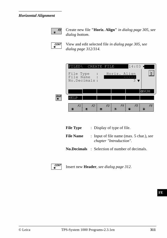
© Leica TPS-System 1000 Programs-2.3.1en 311
IV
EL
AH
OH
BS
SM
AS
FS
BL
HB
KM
FB
SA
PZ
LB
TB
CO
RP
FE
Horizontal Alignment
Create new file "Horiz. Align" in dialog page 305, seedialog bottom.
View and edit selected file in dialog page 305, seedialog page 312/314.
FILED\ CREATE FILE 14:03
αNUM
F1 F2 F3 F4 F5 F6
HELP
MCFile Type : Horiz. Align
File Name : -----No.Decimals : 3
File Type : Display of type of file.
File Name : Input of file name (max. 5 char.), seechapter "Introduction".
No.Decimals : Selection of number of decimals.
Insert new Header, see dialog page 312.

312 TPS-System 1000 Programs-2.3.1en © Leica
IV
EL
AH
OH
BS
SM
AS
FS
BL
HB
KM
FB
SA
PZ
LB
TB
CO
RP
FE
FilEd\ VIEW / EDIT FILE 14:03
SAVE INSRT αNUM
F1 F2 F3 F4 F5 F6
HELP |<-- -->| SEARC
MC1/ 1
Job Id : JOB_IDFile Id : HZALIGNMFile Type : STACOORD
1/ 1 : Sequence number of current point andtotal number of points in themeasurement set. The scroll bar showsthe sequential position of themeasurements, graphically.
Job Id : Input of job identification.
File Id : Display of horizontal alignment file.
File Type : Display for the main point method.
Save file.
Insert new data set.
Goto start of file.
Goto end of file.
Point search.

© Leica TPS-System 1000 Programs-2.3.1en 313
IV
EL
AH
OH
BS
SM
AS
FS
BL
HB
KM
FB
SA
PZ
LB
TB
CO
RP
FE
INSERT RECORD 14:03
MC1 Insert Tangent
2 Insert Circular Curve3 Insert Spiral In4 Insert Spiral Out5 Insert Curve In6 Insert Curve Out
Insert Tangent.
Insert Circular Curve.
Insert Spiral In.
Insert Spiral Out.
Insert Curve In, see dialog page 314.
Insert Curve Out.
Insert End Of Positioning.
The function "Insert Curve In" is used as an example.For the other functions refer to dialog page 314.
7 Insert End Of Positioning
F1 F2 F3 F4 F5 F6
HELP

314 TPS-System 1000 Programs-2.3.1en © Leica
IV
EL
AH
OH
BS
SM
AS
FS
BL
HB
KM
FB
SA
PZ
LB
TB
CO
RP
FE
Call function "Insert Curve In " in menu "INSERTRECORD" (page 313).
FilEd\ VIEW / EDIT FILE 14:03
<-- --> SAVE INSRT IMPOR EDIT
MC2/ 3
Station : 0.000 mEle Type : Curve InRadius 1 : 0.000 mTemplate : TEMPLATERadius 2 : 0.000 m
Easting : 0.000 mNorthing : 0.000 m
2/ 3 : Sequence number of current point andtotal number of points in themeasurement set. The scroll bar showsthe sequential position of themeasurements, graphically.
Station : Input of station (chainage).
Ele Type : Display of geometric element.
Radius 1 : Input of circular curve radius 1.
Template : Input of name/number of crosssection.
Radius 2 : Input of circular curve radius 2.
Easting : Input of easting.
Northing : Input of northing.
F1 F2 F3 F4 F5 F6
HELP |<-- -->| DEL SEARC

© Leica TPS-System 1000 Programs-2.3.1en 315
IV
EL
AH
OH
BS
SM
AS
FS
BL
HB
KM
FB
SA
PZ
LB
TB
CO
RP
FE
Display of previous point.
Display of following point.
Save file.
Insert new data set.
Import of coordinates either by manual input or byreading in the active coordinate file. This function isdescribed in chapter "Select user template ..." of the"SYSTEM" Users Manual.
Goto start of file.
Goto end of file.
Delete a data block.
Point search.

316 TPS-System 1000 Programs-2.3.1en © Leica
IV
EL
AH
OH
BS
SM
AS
FS
BL
HB
KM
FB
SA
PZ
LB
TB
CO
RP
FE
Start dialog "SEARCH" in the dialogs "View / EditFile" (pages 312, 314).
FilEd\ SEARCH 14:03
SEARC EDIT
F1 F2 F3 F4 F5 F6
HELP
MCDirection : Forward
Station : ----- m
Direction : Forward : Searching for station indirection end of file.Backward: Searching for station indirection start of file.
Station : Input of station (chainage).
Search for station. or
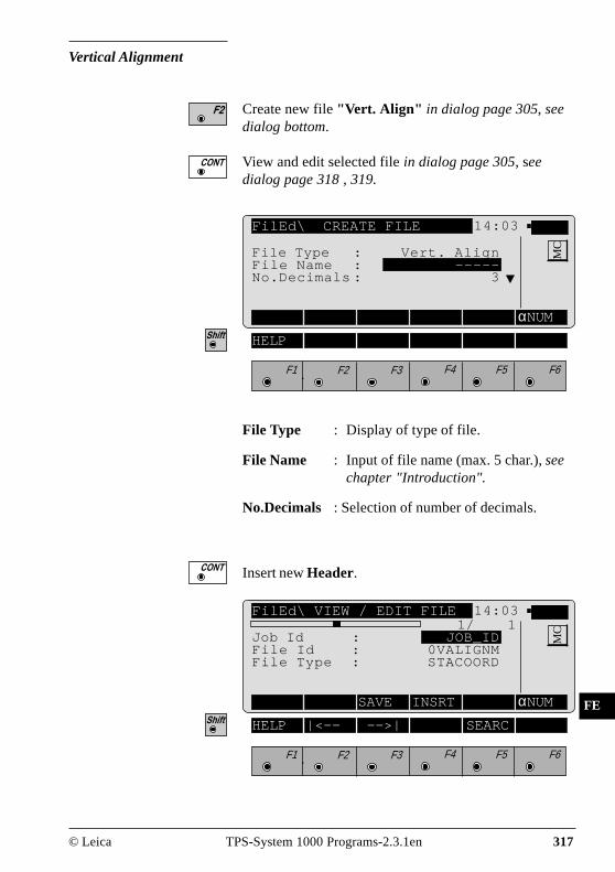
© Leica TPS-System 1000 Programs-2.3.1en 317
IV
EL
AH
OH
BS
SM
AS
FS
BL
HB
KM
FB
SA
PZ
LB
TB
CO
RP
FE
Vertical Alignment
Create new file "Vert. Align" in dialog page 305, seedialog bottom.
View and edit selected file in dialog page 305, seedialog page 318 , 319.
FilEd\ CREATE FILE 14:03
αNUM
F1 F2 F3 F4 F5 F6
HELP
MCFile Type : Vert. Align
File Name : -----No.Decimals : 3
File Type : Display of type of file.
File Name : Input of file name (max. 5 char.), seechapter "Introduction".
No.Decimals : Selection of number of decimals.
Insert new Header.
FilEd\ VIEW / EDIT FILE 14:03
SAVE INSRT αNUM
F1 F2 F3 F4 F5 F6
HELP |<-- -->| SEARC
MC1/ 1
Job Id : JOB_IDFile Id : 0VALIGNMFile Type : STACOORD

318 TPS-System 1000 Programs-2.3.1en © Leica
IV
EL
AH
OH
BS
SM
AS
FS
BL
HB
KM
FB
SA
PZ
LB
TB
CO
RP
FE
1/ 1 : Sequence number of current point andtotal number of points in themeasurement set. The scroll bar showsthe sequential position of themeasurements, graphically.
Job Id : Input of job identification.
File Id : Display for the vertical alignment file.
File Type : Display for the main point method.
Meaning of the function keys is similar to dialog page312.
INSERT RECORD 14:03
MC1 Insert Tangent
2 Insert Circular Curve3 Insert Parabola4 Insert End Of Positioning
F1 F2 F3 F4 F5 F6
HELP
Insert Tangent.
Insert Circular Curve.
Insert Parabola, see dialog page 319.
Insert End Of Positioning.
The function "Insert parabola" is used as an example.For the other functions refer to dialog page 319.

© Leica TPS-System 1000 Programs-2.3.1en 319
IV
EL
AH
OH
BS
SM
AS
FS
BL
HB
KM
FB
SA
PZ
LB
TB
CO
RP
FE
2/ 3 : Sequence number of current point andtotal number of points in themeasurement set. The scroll bar showsthe sequential position of themeasurements, graphically.
Station : Input of station (chainage).
Ele Type : Display of geometric element.
Parameter : Input of parabola parameter.
Elevation : Input of elevation.
Meaning of the function keys is similar to dialog page314.
FilEd\ VIEW / EDIT FILE 14:03
<-- --> SAVE INSRT IMPOR EDIT
MC2/ 3
Station : 0.000 mEle Type : ParabolaParameter : 0.000 mElevation : 0.000 m
F1 F2 F3 F4 F5 F6
HELP |<-- -->| DEL SEARC
Call function "Insert Parabola" in menu "INSERTRECORD" (page 318).

320 TPS-System 1000 Programs-2.3.1en © Leica
IV
EL
AH
OH
BS
SM
AS
FS
BL
HB
KM
FB
SA
PZ
LB
TB
CO
RP
FE
Start dialog "SEARCH" in the dialogs "View / EditFile" (pages 317, 319).
FilEd\ SEARCH 14:03
SEARC EDIT
F1 F2 F3 F4 F5 F6
HELP
MCDirection : Forward
Station : ----- m
Direction : Forward : Searching for station indirection end of file.Backward: Searching for station indirection start of file.
Station : Input of station (chainage).
Search for station. or

© Leica TPS-System 1000 Programs-2.3.1en 321
IV
EL
AH
OH
BS
SM
AS
FS
BL
HB
KM
FB
SA
PZ
LB
TB
CO
RP
FE
Template
Create new file "Template" in dialog page 305, seedialog bottom.
View and editselected file in dialog page 305, seedialoges page 322/323.
FilEd\ CREATE FILE 14:03
αNUM
F1 F2 F3 F4 F5 F6
HELP
MCFile Type : Template
File Name : -----No.Decimals: 3
File Type : Display of type of file.
File Name : Input of file name (max. 5 char.), seechapter "Introduction".
No.Decimals : Selection of number of decimals.
Insert new Header, see dialog page 322.

322 TPS-System 1000 Programs-2.3.1en © Leica
IV
EL
AH
OH
BS
SM
AS
FS
BL
HB
KM
FB
SA
PZ
LB
TB
CO
RP
FE
FilEd\ VIEW / EDIT FILE 14:03
SAVE INSRT αNUM
F1 F2 F3 F4 F5 F6
HELP |<-- -->| SEARC
MC1/ 1
Job Id : JOB_IDFile Id : TEMPLATE
1/ 1 : Sequence number of current point andtotal number of points in themeasurement set. The scroll bar showsthe sequential position of themeasurements, graphically.
Job Id : Input of job identification.
File Id : Display of cross section file.
Meaning of the function keys is similar to dialog page312.

© Leica TPS-System 1000 Programs-2.3.1en 323
IV
EL
AH
OH
BS
SM
AS
FS
BL
HB
KM
FB
SA
PZ
LB
TB
CO
RP
FE
FilEd\ VIEW / EDIT FILE 14:03
<-- --> SAVE INSRT EDIT
F1 F2 F3 F4 F5 F6
HELP |<-- -->| DEL SEARC
MC2/ 3
Template : TEMPLATE∆Hz-Dist. : 0.000 mSO Ht diff : 0.000 mCut/Fill : FILLSlope ratio : 0.000
2/ 3 : Sequence number of current point andtotal number of points in themeasurement set. The scroll bar showsthe sequential position of themeasurements, graphically.
Template : Input of name/number of cross sectionpoint.
∆∆∆∆∆Hz-Dist. : Input of horiz. distance of crosssection point.
SO Ht diff : Input of nom. height difference ofcross section point to axis.
Cut/Fill : Selection of cross section type.Available are:CUTFILLSTANDARD
Slope ratio : Input of slope ratio.
Meaning of the function keys is similar to dialog page314.

324 TPS-System 1000 Programs-2.3.1en © Leica
IV
EL
AH
OH
BS
SM
AS
FS
BL
HB
KM
FB
SA
PZ
LB
TB
CO
RP
FE
Start dialog "SEARCH" in the dialogs "View / EditFile" (pages 322, 323).
FilEd\ SEARCH 14:03
SEARC αNUM
F1 F2 F3 F4 F5 F6
HELP
MCDirection : Forward
Template : -----
Direction : Forward : Searching for templatesin direction end of file.Backward: Searching for templatesin direction start of file.
Template : Input of template name.
Search for templates. or

© Leica TPS-System 1000 Programs-2.3.1en 325
IV
EL
AH
OH
BS
SM
AS
FS
BL
HB
KM
FB
SA
PZ
LB
TB
CO
RP
FE
Station Equation
Create new file "Sta. Eqn." in dialog page 305, seedialog bottom.
View and edit selected file in dialog page 305, seedialogs page 326/327.
FilEd\ CREATE FILE 14:03
αNUM
F1 F2 F3 F4 F5 F6
HELP
MCFile Type : Sta. Eqn.
File Name : -----No.Decimals : 3
File Type : Display of type of file.
File Name : Input of file name (max. 5 char.), seechapter "Introduction".
No.Decimals : Selection of number of decimals.
Insert new Header, see dialog page 326.

326 TPS-System 1000 Programs-2.3.1en © Leica
IV
EL
AH
OH
BS
SM
AS
FS
BL
HB
KM
FB
SA
PZ
LB
TB
CO
RP
FE
FilEd\ VIEW / EDIT FILE 14:03
SAVE INSRT αNUM
F1 F2 F3 F4 F5 F6
HELP |<-- -->| SEARC
MC1/ 1
Job Id : JOB_IDFile Id : 0STAEQTN
1/ 1 : Sequence number of current point andtotal number of points in themeasurement set. The scroll bar showsthe sequential position of themeasurements, graphically.
Job Id : Input of job identificaton.
File Id : Display for the station equation file.
Meaning of the function keys is similar to dialog page312.

© Leica TPS-System 1000 Programs-2.3.1en 327
IV
EL
AH
OH
BS
SM
AS
FS
BL
HB
KM
FB
SA
PZ
LB
TB
CO
RP
FE
FilEd\ VIEW / EDIT FILE 14:03
<-- --> SAVE INSRT αNUM
MC2/ 3
Sta. Eqn. : 0Ahead : 0.000 mBack : 0.000 m
F1 F2 F3 F4 F5 F6
HELP |<-- -->| DEL SEARC
2/ 3 : Sequence number of current point andtotal number of points in themeasurement set. The scroll bar showsthe sequential position of themeasurements, graphically.
Sta. Eqn. : Input of number of station equation.
Ahead : Input of station ahead.
Back : Input of station back.
Meaning of the function keys is similar to dialog page314.

328 TPS-System 1000 Programs-2.3.1en © Leica
IV
EL
AH
OH
BS
SM
AS
FS
BL
HB
KM
FB
SA
PZ
LB
TB
CO
RP
FE
FilEd\ SEARCH 14:03
SEARC αNUM
F1 F2 F3 F4 F5 F6
HELP
MCDirection : Forward
Sta. Eqn. : -----
Direction : Forward : Searching for stationequations in direction end of file.Backward: Searching for stationequations in direction start of file.
Sta. Eqn. : Input of number of station equation.
Search for station equations.
Start dialog "SEARCH" in dialogs "View / Edit File"(pages 326, 327).
or

© Leica TPS-System 1000 Programs-2.3.1en 329
IV
EL
AH
OH
BS
SM
AS
FS
BL
HB
KM
FB
SA
PZ
LB
TB
CO
RP
FE
Cross-section Assignment
Create new file "CRS Assignmnt" in dialog page 305,see dialog bottom.
View and edit selected file in dialog pagee 305, seedialogs page 330/331.
FilEd\ CREATE FILE 14:03
αNUM
F1 F2 F3 F4 F5 F6
HELP
MCFile Type : CRS Assignmnt
File Name : -----No.Decimals: 3
File Type : Display of type of file.
File Name : Input of file name (max. 5 char.), seechapter "Introduction".
No.Decimals : Selection of number of decimals.
Insert new Header, see dialog page 330.

330 TPS-System 1000 Programs-2.3.1en © Leica
IV
EL
AH
OH
BS
SM
AS
FS
BL
HB
KM
FB
SA
PZ
LB
TB
CO
RP
FE
FilEd\ VIEW / EDIT FILE 14:03
SAVE INSRT αNUM
F1 F2 F3 F4 F5 F6
HELP |<-- -->| SEARC
MC1/ 1
Job Id : JOB_IDFile Id : ASSIGNMTCRS File : CRSCCCCC.GSI
1/ 1 : Sequence number of current point andtotal number of points in themeasurement set. The scroll bar showsthe sequential position of themeasurements, graphically.
Job Id : Input of job identification.
File Id : Display of section assignment file.
CRS File : Selection of relevant cross section file.
Meaning of the function keys is similar to dialog page312.

© Leica TPS-System 1000 Programs-2.3.1en 331
IV
EL
AH
OH
BS
SM
AS
FS
BL
HB
KM
FB
SA
PZ
LB
TB
CO
RP
FE
FilEd\ VIEW / EDIT FILE 14:03
<-- --> SAVE INSRT LIST
MC2/ 3
Template : TEMPLATEStation : 0.000 m
F1 F2 F3 F4 F5 F6
HELP |<-- -->| DEL SEARC
2/ 3 : Sequence number of current point andtotal number of points in themeasurement set. The scroll bar showsthe sequential position of themeasurements, graphically.
Template : Selection of template.
Station : Input of start station for this template.
Meaning of the function keys is similar to dialog page314.

332 TPS-System 1000 Programs-2.3.1en © Leica
IV
EL
AH
OH
BS
SM
AS
FS
BL
HB
KM
FB
SA
PZ
LB
TB
CO
RP
FE
FilEd\ SEARCH 14:03
SEARC EDIT
F1 F2 F3 F4 F5 F6
HELP
MCDirection : Forward
Station : ----- m
Direction : Forward : Searching for templatesin direction end of file.Backward: Searching for templatesin direction start of file.
Station : Input of station (chainage).
Search for station.
Start dialog "SEARCH" in dialogs "View / Edit File"(pages 330, 331).
or

© Leica TPS-System 1000 Programs-2.3.1en 333
IV
EL
AH
OH
BS
SM
AS
FS
BL
HB
KM
FB
SA
PZ
LB
TB
CO
RP
DE
MO
The manual describes the "Monitoring" program of theLeica TPS SYSTEM 1000 theodolite series.The program allows for automatic measurementrepetition.
Monitoring
Introduction
The instrument must be firmly mounted on a tripod orpillar.
Requirements to run this program:• the licence number• a PCMCIA card which is inserted into the instrument
By means of a timer function, the program can triggerthe automatic measurement, at predetermined intervals,of points which have already been measured once andlearned by the instrument and which are stored on thePCMCIA card.
Max. 50 measuring points and as many measurementrepetitions as desired, at any time intervals.
MO
NI-
01

334 TPS-System 1000 Programs-2.3.1en © Leica
IV
EL
AH
OH
BS
SM
AS
FS
BL
HB
KM
FB
SA
PZ
LB
TB
CO
RP
DE
MO
The measurements can be:• repeated as often as is necessary,• at any time• performed in both faces.
The point number, the horizontal and vertical anglesand the slope distance for the individual measurementsare stored on the memory card.
The points to be measured must be permanentlyequipped with Leica prisms.The measurements are limited only by the storagecapacity of the PCMCIA memory card.

© Leica TPS-System 1000 Programs-2.3.1en 335
IV
EL
AH
OH
BS
SM
AS
FS
BL
HB
KM
FB
SA
PZ
LB
TB
CO
RP
DE
MO
Main menu
MONIT\ MONITORING MENU 14:03
INFO
HELP
MC1 Point Selection
2 Timer Selection3 Point Measurement4 End Monitoring
F1 F2 F3 F4 F5 F6
Selection of points to be measured, see page 336.
Set timer requirements, see page 339.
Start point measurement, see page 340.
Exit the "Monitoring" program.

336 TPS-System 1000 Programs-2.3.1en © Leica
IV
EL
AH
OH
BS
SM
AS
FS
BL
HB
KM
FB
SA
PZ
LB
TB
CO
RP
DE
MO
Selecting points The points to be measured are selected from this menu:• by storing the appropriate measurement file, points
already measured at the same station• by entering the LEARNED file, points yet to be
determined.
MONIT\ POINT SELECTION 14:03
MEAS SELCT LIST
HELP
MCControl : LEARNED
Total Pts. : 24Select Pts. : 24Two Faces : YES
To learn points, the "LEARNED" file must be used as acontrol file.
To use points from another file, use (LIST) toswitch to the file selection und wählen die gewünschteDatei.The point file must:• be in the GSI directory on the PCMCIA card,• include the point numbers and the angle
measurements.The instrument itself must have been positioned.
With the "Two Faces" option you can alternate betweenone-face and two-face measurement.If you choose the two-face option, every singlemeasurement is stored on the PCMCIA card.
Calls the measurement menu, for first-time pointmeasurement.
Calls the point selection.
Selects from the list of GSI files.
F1 F2 F3 F4 F5 F6

© Leica TPS-System 1000 Programs-2.3.1en 337
IV
EL
AH
OH
BS
SM
AS
FS
BL
HB
KM
FB
SA
PZ
LB
TB
CO
RP
DE
MO
Measurement menu MONIT\ LEARN POINT 14:03
ALL DIST REC TARGT DONE αNUM
HELP I<>II
MC
If the measurement file already includes points with thesame point number, then when this function is calledyou will be asked whether the points are to be writtenover.
For the instrument to learn a point, the prism must betargeted manuallyTriggering the distance measurement then initiates adistance measurement and a precise determination ofthe angle.
Measure the distance.
Store the measurement into the selected file.
Quit the function after all points have been measured;return to the "POINT SELECTION" menu.
(ALL) does not have any functions, for
measuring and recording it is imperative to use
and .
The points will be saved in the set measurement file(refer to chapter "Select user template andmeasurement file" of "System" - user manual).
Point no. : 2Remark 1 : -----Refl.Height : 0.0000 mHz : 281°47'05"V : 92°15'36"Horiz.Dist. : 145.4821 m ñ
F1 F2 F3 F4 F5 F6
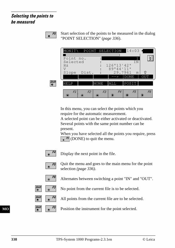
338 TPS-System 1000 Programs-2.3.1en © Leica
IV
EL
AH
OH
BS
SM
AS
FS
BL
HB
KM
FB
SA
PZ
LB
TB
CO
RP
DE
MO
Selecting the points tobe measured
Start selection of the points to be measured in the dialog"POINT SELECTION" (page 336).
ALL DIST REC ZIEL ENDE αNUM
F1 F2 F3 F4 F5 F6
HELP NONE ALL POSIT
MONIT\ POINT SELECTION 14:03
--> DONE OUT
MCPoint no. : 1
Selected : INHz : 126°13'42"V : 89°44'11"Slope Dist. : 29.7961 m ñ
In this menu, you can select the points which yourequire for the automatic measurement.A selected point can be either activated or deactivated.Several points with the same point number can bepresent.When you have selected all the points you require, press
(DONE) to quit the menu.
Display the next point in the file.
Quit the menu and goes to the main menu for the pointselection (page 336).
Alternates between switching a point "IN" and "OUT".
No point from the current file is to be selected.
All points from the current file are to be selected.
Position the instrument for the point selected.

© Leica TPS-System 1000 Programs-2.3.1en 339
IV
EL
AH
OH
BS
SM
AS
FS
BL
HB
KM
FB
SA
PZ
LB
TB
CO
RP
DE
MO
Timer selection MONIT\ TIMER SELECTION 14:03
EDIT
HELP
MC
This menu decides when the measurement will be taken.
Enter the date and time for the beginning and end of themeasurement.An interval of at least one minute betweenmeasurements must be defined.The number of repeats can be defined in the field"Repetitions".
Edit the preset values.
Beg Date : 18/07/97Beg Time : 16:00:00End Date : 30/08/97End Time : 00:00:00Delay : 0h 1mRepetitions : 2
F1 F2 F3 F4 F5 F6

340 TPS-System 1000 Programs-2.3.1en © Leica
IV
EL
AH
OH
BS
SM
AS
FS
BL
HB
KM
FB
SA
PZ
LB
TB
CO
RP
DE
MO
Point measurement Choosing this option starts the measurement.If a point cannot be measured, the TCA starts its internalsearch routine and, if unsuccessful, goes on to the nextpoint to be measured.
Abort the automatic measurement.
End monitoring This option terminates the "Monitoring" program.

© Leica TPS-System 1000 Programs-2.3.1en 341
IV
EL
AH
OH
BS
SM
AS
FS
BL
HB
KM
FB
SA
PZ
LB
TB
IX
Index
A Abort 340Abscissa 238, 241Additional applications 16Alignment 175Angular correction 168Arcs 120Area 117Azimuth and distance 64
B Backsight azimuth 152Base point 106, 238Baseline points 95
C Calling up the program 25Calls ON-LINE help 26Calls up code input 26CAUTION 4Centre-line offset 171Chainage 171Closes application 26Coarse positioning 60COGO 205Computation of area 117Create coordinate file 306Create cross-section assignment file 329Create horizontal alignment file 311Create station equation file 325Create template file 321Create vertical alignment file 317Cross section assignment 259, 298Cross section interpolation 260Cross sections 180, 201, 296

342 TPS-System 1000 Programs-2.3.1en © Leica
IV
EL
AH
OH
BS
SM
AS
FS
BL
HB
KM
FB
SA
PZ
LB
TB
IX
D DANGER 4Data exchange 24Designation of keys 26Determination of the station elevation 27Direction measurements 129
F File editor 303Free station 79
G General notes 23
H Hidden point 111Hz-alignment 192, 291
I Important paragraphs 4Installation in the PC 12Instrument field setup 24Intersections 221Introduction 11Inverse 209
L Licence code 11, 21Line offset 60Loading application programs 20Loading system texts 19Local coordinates 165Local resection 165Local station elevation 165

© Leica TPS-System 1000 Programs-2.3.1en 343
IV
EL
AH
OH
BS
SM
AS
FS
BL
HB
KM
FB
SA
PZ
LB
TB
IX
M Measurement file 336, 337Measurement menu 337Measurement repetition 333Monitoring 333
N Naming files 15
O Offsets 237Ordinate 238, 241Orientation 79, 83, 168Orientation and height transfer 27Orientation correction27, 32, 38, 44, 47, 84, 90, 168Oriented direction 31, 43, 83Orthogonal 62Orthogonal stakeout 68
P PCMCIA memory card 334Perimeter 123, 124Point measurement 340Polar calculation 209Polar stakeout 66Pole 111Polygon mode 53, 54Polygonal mode 49, 58Product identification 3Project files 303
R Radial methods 49Radial mode 50, 53, 54Reference line 93, 98Reference point 289Remote height 105Remote point 108Resection 39Road line 171Road plus 249

344 TPS-System 1000 Programs-2.3.1en © Leica
IV
EL
AH
OH
BS
SM
AS
FS
BL
HB
KM
FB
SA
PZ
LB
TB
IX
S Scale factor 84Select stakeout method 74Selecting points 336Sets of angles 129Sideshot 153Sideshot point 154, 155Sideshots 147Slope staking 285Software upload 17Stakeout 59, 66, 183Stakeout from coordinate differences 72Stakeout with auxiliary points 70Standard applications 11, 16Station equations 262, 300Superelevation 261
T Three point arc 246Tie distance 49Timer selection 339TRANSFER 19, 20Traverse 147, 212Traverse point 153, 154, 155Two faces 336
U Units in this manual 23Using the program 24
V V-alignment 197, 294
W WARNING 4WORKBENCH 13, 14
X X-section Check 184

© Leica TPS-System 1000 Programs-2.3.1en 345
IV
EL
AH
OH
BS
SM
AS
FS
BL
HB
KM
FB
SA
PZ
LB
TB
IX
Leica Geosystems AG,Heerbrugg, Switzerlandhas been certified as beingequipped with a qualitysystem which meets theInternational Standard ofQuality Management andQuality Systems(ISO standard 9001)
Total Quality Management-Our commitment to totalcustomer satisfaction
Ask your local Leica agent formore information about ourTQM program

Leica Geosystems AGGeodesy
CH-9435 Heerbrugg(Switzerland)
Phone +41 71 727 31 31Fax +41 71 727 46 73
www.leica.comPrinted in switzerland - Copyright Leica Geosystems AG, Heerbrugg,Switzerland 1998Translation of original text (664901-2.3.1de)
664901-2.3.1en