Embed Size (px)
Citation preview
TotalPlant Solution (TPS) System
TPS System Overview
TP01100R10011/98
ii TPS System Overview 11/98Honeywell Inc. R100
Notices and Trademarks
Copyright 1998 by Honeywell Inc.
November 25, 1998
While this information is presented in good faith and believed to be accurate,Honeywell disclaims the implied warranties of merchantability and fitness for aparticular purpose and makes no express warranties except as may be stated in itswritten agreement with and for its customers.
In no event is Honeywell liable to anyone for any indirect, special or consequentialdamages. The information and specifications in this document are subject to changewithout notice.
Honeywell, TotalPlant, and TDC 3000 are U.S. registered trademarks of HoneywellInc.
Other brand or product names are trademarks of their respective owners.
Honeywell Inc.
Industrial Automation and Control
Automation College
2820 West Kelton Lane
Phoenix, AZ 85053-3028
1 (800) 852-3211
11/98 TPS System Overview iiiR100 Honeywell Inc.
About This Document
References
Honeywell Documents
The following list identifies TPS Honeywell documents that may be sources of reference for thematerial discussed in this publication. These publications are also sent on CD-ROM
Document Title Doc. ID
System Overview SW70-500
ContactsThe following lists identify important contacts within Honeywell.
World Wide Web
Honeywell provides internet access to several of Honeywell World Wide Web sites. Thefollowing lists those sites of interest to our industrial customers.
Organization WWW Address (URL)
Honeywell Inc. http://www.honeywell.COM
Honeywell Industrial Automation and Control http://www.iac.honeywell.COM
Sales and Service
Location Organization Phone Number
United States and Canada Honeywell IACPhoenix, Arizona
1-800-343-0228Sales
1-800-525-7439Service
Outside United States andCanada
Your Honeywell Local Affiliate If Local Affiliate isunknown, ask yourcorporate region forthe Local Affiliate’sname and phonenumber.
About This Document
iv TPS System Overview 11/98Honeywell Inc. R100
Corporate Regions
Global Location Organization Phone Number
Asia Pacific Honeywell Asia Pacific Inc.Hong Kong
(852) 8298298
Europe Honeywell PACEBrussels, Belgium
[32-2] 728-2111
Latin America Honeywell Inc.Sunrise, Florida U.S.A.
(305) 364-2355
11/98 TPS System Overview vR100 Honeywell Inc.
Contents
INTRODUCTION..................................................................................... 9
Overview......................................................................................................................9
Functional Overview ................................................................................................10Scope .................................................................................................................................. 10TPS System Components (Control) .................................................................................... 11
PRODUCT STRUCTURE ..................................................................... 19
TPS System Driving Forces.....................................................................................19
TPS System Characteristics....................................................................................19TPS System Composition.................................................................................................... 19TPS System Concepts ........................................................................................................ 20
TPS System Component Connectivity ...................................................................22Node Roles in TPS System ................................................................................................. 22TPS System Configurations ................................................................................................ 24
Product Packaging ...................................................................................................26
PRODUCT OVERVIEW........................................................................ 27
Hardware ...................................................................................................................27LCNP4................................................................................................................................. 27TPS System Ready Consoles ............................................................................................. 28Intel-Based Platforms .......................................................................................................... 28
Global User Station (GUS).......................................................................................28Base System ....................................................................................................................... 29Multiple Displays.................................................................................................................. 29GUS Display Server (local TPN Data) ................................................................................. 29HCI Named Data Access..................................................................................................... 29GUS Utilizing IOMaps.......................................................................................................... 29GUS Standard Displays....................................................................................................... 30SafeView ............................................................................................................................. 30Reusable Components ........................................................................................................ 30TPSDDE.............................................................................................................................. 30
Uniformance Desktop ..............................................................................................31Process Trend ..................................................................................................................... 31TDC Viewer ......................................................................................................................... 31
Contents
vi TPS System Overview 11/98Honeywell Inc. R100
Scheduler ............................................................................................................................ 32Visual PHD.......................................................................................................................... 32Example Excel Spreadsheet ............................................................................................... 32Interactive Query................................................................................................................. 33Dynamic Query (DQ) and Microsoft Query (MQ)................................................................. 33History Browser................................................................................................................... 33
Process History Database (PHD)............................................................................ 33Multiple Data Types Supported........................................................................................... 33Tag Configuration................................................................................................................ 34Class Tag Configuration...................................................................................................... 34Data Retrieval Independent of Data Collection ................................................................... 34Time Weighted Data Reductions ........................................................................................ 34Automatic Engineering Unit Conversions............................................................................ 34Virtual Calculations ............................................................................................................. 34Conditional Data Search and Retrieval ............................................................................... 35System Capacity ................................................................................................................. 35Exception Condition Interfaces ........................................................................................... 35Automated Backup.............................................................................................................. 35Data Compression .............................................................................................................. 35HCI PHD Server .................................................................................................................. 36TPN Event Journal Collection and Storage......................................................................... 36
Application Program Execution ............................................................................. 36NT Client Applications......................................................................................................... 37CL Server ............................................................................................................................ 37Application I/O..................................................................................................................... 38
Event Annunciation and Journal Entries .............................................................. 39
System Management ............................................................................................... 40Performance and Network Management............................................................................. 40Security Management ......................................................................................................... 41System Configuration.......................................................................................................... 41
Build Environment ................................................................................................... 42TPS Builder ......................................................................................................................... 42PHD Configuration .............................................................................................................. 42Display Translator ............................................................................................................... 43Display Builder .................................................................................................................... 43SafeView Editor................................................................................................................... 43HCI Client Toolkit ................................................................................................................ 43HCI Server Toolkit ............................................................................................................... 44
Distributed Communication (HCI/OPC) ................................................................. 44Value Added Functions and Robustness ............................................................................ 45TPS System Naming Structure ........................................................................................... 45
Contents
11/98 TPS System Overview viiR100 Honeywell Inc.
SECURITY............................................................................................ 47
Security Approach....................................................................................................47NT Domain .......................................................................................................................... 47TPS Domain ........................................................................................................................ 47User ID Verification.............................................................................................................. 47Access Rights...................................................................................................................... 48Security Objects .................................................................................................................. 48Permissions......................................................................................................................... 48Proxy Files........................................................................................................................... 48User Groups ........................................................................................................................ 48Operators ............................................................................................................................ 49Interactive User Interface .................................................................................................... 49TPSDDE and File Transfer.................................................................................................. 49PHD..................................................................................................................................... 50Security Objects and Access Control Mechanisms ............................................................. 51
RELATED PRODUCTS AND APPLICATIONS.................................... 53
Network and Integration Services...........................................................................53
User Alert ..................................................................................................................53
Equipment Health Management (EHM) ..................................................................53
Advanced Control Applications..............................................................................54Profit Suite........................................................................................................................... 54Oil Movements and Storage ................................................................................................ 55TotalPlant Batch ................................................................................................................... 55
GLOSSARY.......................................................................................... 57
Acronyms and Abbreviations..................................................................................57
Terminology ..............................................................................................................59
Tables and Figures
viii TPS System Overview 11/98Honeywell Inc. R100
Tables and FiguresTable 1 TPS System Security Objects and Access Control Mechanisms .............................. 51
Figure 1 TPS System ............................................................................................................. 10
Figure 2 TPS Hardware Components .................................................................................... 12
Figure 3 TPS Software Components ..................................................................................... 13
Figure 4 Node Roles in TPS System...................................................................................... 22
Figure 5 Minimum TPS System Configuration ....................................................................... 24
Figure 6 Typical TPS System Configuration .......................................................................... 25
Figure 7 Large TPS System Configuration ............................................................................ 26
Figure 8 Communication Interface Structure.......................................................................... 44
11/98 TPS System Overview 9R100 Honeywell Inc.
Introduction
OverviewThe TPS (TotalPlant Solution) System Overview document provides a high leveldescription of Honeywell IAC’s open automation system intended for use on projectsfrom small to very large. The TPS system is the evolution of the TDC 3000X system(now called TPS Network) and includes all the capabilities of that system, as well asmany new capabilities. The TPS components, such as the human interface andapplication platform, are described here, as well as the unified and consistent approachfor accessing data and managing system resources.
Introduction – Functional Overview
10 TPS System Overview 11/98Honeywell Inc. R100
Functional Overview
Scope
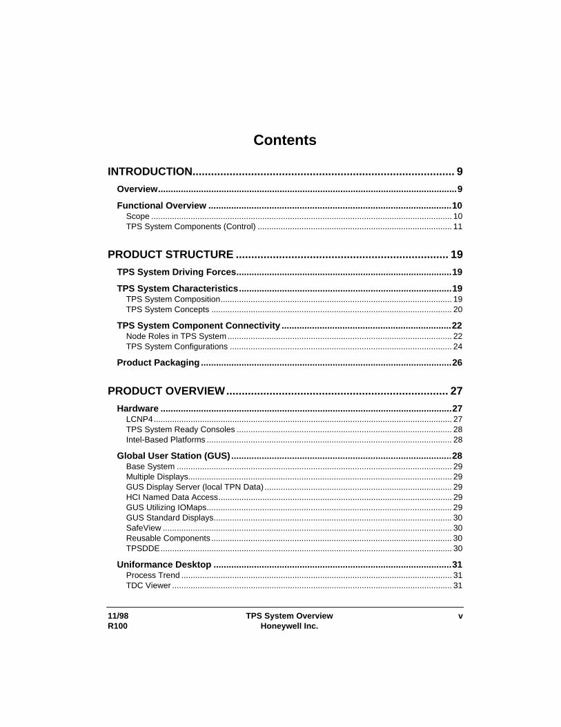
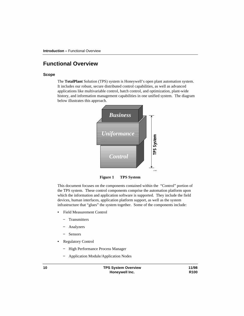
The TotalPlant Solution (TPS) system is Honeywell’s open plant automation system.It includes our robust, secure distributed control capabilities, as well as advancedapplications like multivariable control, batch control, and optimization, plant-widehistory, and information management capabilities in one unified system. The diagrambelow illustrates this approach.
Business
TPS
Syst
em
Uniformance
Control
17392
Figure 1 TPS System
This document focuses on the components contained within the “Control” portion ofthe TPS system. These control components comprise the automation platform uponwhich the information and application software is supported. They include the fielddevices, human interfaces, application platform support, as well as the systeminfrastructure that “glues” the system together. Some of the components include:
• Field Measurement Control
− Transmitters
− Analyzers
− Sensors
• Regulatory Control
− High Performance Process Manager
− Application Module/Application Nodes
Introduction – Functional Overview
11/98 TPS System Overview 11R100 Honeywell Inc.
− Global User Station/Universal Station
− History Module/Process History Database
− Fail Safe Controller
This document does not cover the information management applications, advanced control applications or Honeywell services, nor does it dwell on TPS systemcomponents fully documented in other publications, such as TPS Network or FieldInstruments. A description of several Uniformance products can be found in the sectionentitled Related Products and Applications. While not all Uniformance products arerepresented there, all are well integrated with TPS Control to complete the TPS system.
TPS System Components (Control)
The TPS system is designed to meet the needs of large systems while being scaleable torelatively small systems. TPS system key features include the following:
• Openness
• Smart field devices
• State-of-the-art human interface
• Advanced engineering tools
• Real-time database and plant-wide historian
• Open application environment
• Proven robust and secure control environment
• Open interface to enterprise management applications
TPS system’s unifying infrastructure pulls these features together into a completesystem.
Introduction – Functional Overview
12 TPS System Overview 11/98Honeywell Inc. R100
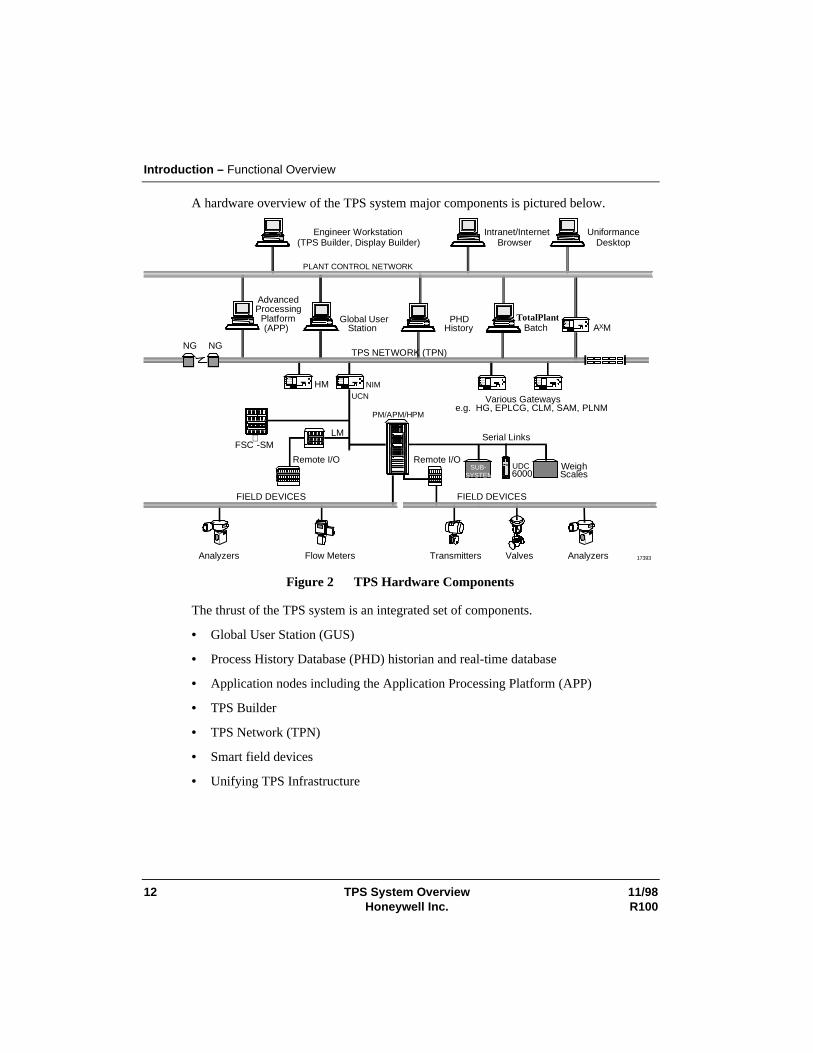
A hardware overview of the TPS system major components is pictured below.
SUB-SYSTEM
AXM
HM
PHDHistory
Global UserStation
AdvancedProcessing
Platform(APP)
Engineer Workstation(TPS Builder, Display Builder)
Intranet/InternetBrowser
TotalPlantBatch
UniformanceDesktop
Remote I/O
Analyzers Flow Meters Transmitters Valves Analyzers
FIELD DEVICES
TPS NETWORK (TPN)
PLANT CONTROL NETWORK
FIELD DEVICES
LM
NGNG
Remote I/O
Serial Links
UDC6000
WeighScales
Various Gatewayse.g. HG, EPLCG, CLM, SAM, PLNM
PM/APM/HPM
UCNNIM
17393
FSC -SM
Figure 2 TPS Hardware Components
The thrust of the TPS system is an integrated set of components.
• Global User Station (GUS)
• Process History Database (PHD) historian and real-time database
• Application nodes including the Application Processing Platform (APP)
• TPS Builder
• TPS Network (TPN)
• Smart field devices
• Unifying TPS Infrastructure
Introduction – Functional Overview
11/98 TPS System Overview 13R100 Honeywell Inc.
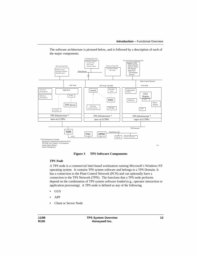
The software architecture is pictured below, and is followed by a description of each ofthe major components.
PC Desktop (NT or 95)
TPS Network
GUS NodeAPP Node with PHD
HCI PHDServer
PHD
GUSDisplay
IO Map
APP Node
IO Map
TPN Server
CL Server
TPN RDI
HCI ClientDeveloper Kit
NIM
Plant Intranet
HPMFSCUCN
amw on LCNPx amw on LCNPx
TPS Infrastructure *
unpw on LCNPx
HOPC
NativeWindow
UniformanceDesktop
HCI ServerDeveloper Kit
Application
SafeView
TPN EventJournal Collection
TPS Client Node for Engineering (NT)
Oracle
TPS Client Node (NT)
Plant Control Network
* TPS Infrastructure includes: Honeywell Communication Interface (HCI) TPS DDE, File Transfer, LCN emulators System Status Monitor System Management
TPS Infrastructure * TPS Infrastructure *
Engineer Tools Display Builder Safeview Editor TPS Builder Application Development Services
HCI/OPC ClientsUniformance DesktopTPS DDE Clients
Uniformance Desktop - Process Trend - TDC Viewer - Interactive Query
Field Device I/O
Valves Smart Transmitters
~~
17394
TPS Server Node (NT)
GUS Native WindowOPC Server
Figure 3 TPS Software Components
TPS Node
A TPS node is a commercial Intel-based workstation running Microsoft’s Windows NToperating system. It contains TPS system software and belongs to a TPS Domain. Ithas a connection to the Plant Control Network (PCN) and can optionally have aconnection to the TPS Network (TPN). The functions that a TPS node performsdepend on the combination of TPS system software loaded (e.g., operator interaction orapplication processing). A TPS node is defined as any of the following.
• GUS
• APP
• Client or Server Node
Introduction – Functional Overview
14 TPS System Overview 11/98Honeywell Inc. R100
Global User Station (GUS)
GUS is a TPS node that has a connection to the TPS Network (TPN) through anLCNP or LCNP4 card and runs a US (unpw) personality. It is packaged in aConsole or Deskside configuration. It is a state-of-the-art human interface andconsists of a Native Window, Display Runtime, and SafeView. The NativeWindow provides all original TPN Universal Station operating and engineeringdisplays in a window on the Global User Station. The Display Runtime componentexecutes GUS displays built by the Display Builder or translated from TPNschematics by the Display Translator. SafeView is a window manager that allows auser to define where types of windows can appear, move to, resize or overlap otherwindows. SafeView can be configured to ensure that critical windows are neverhidden.
GUS is intended for use by operators and engineers to monitor and control theprocess, Honeywell TPS components, and applications. GUS provides historicaltrending from the TPN History Module or from PHD. GUS displays can also getnamed data from a PHD data source or another TPN using HCI named data accessrather than the local connection to the TPN, known as HOPC. This helps keep thelocal TPN loading to a minimum.
Application Processing Platform (APP)
The APP is a TPS node that has a connection to the TPS Network through an LCNP4card and runs either an AM or AMw personality. It is packaged in either a deskside ordesktop configuration. The APP is a state-of-the-art application platform forintegrating advanced control or information management applications. It cancommunicate directly with an existing TPS Network.
The APP contains the TPS system Infrastructure component for communicating to TPNand to HCI/OPC client and server applications in TPS Client and TPS Server nodes. Italso contains other functions such as TPS Status Display, TPS Configuration, FileTransfer and TPSDDE. The CL Server leverages existing Application Module (AM)applications by allowing them to initiate applications that reside in the Windows NTenvironment.
Applications may also be built using the IOMap interface to connect to HCI/OPCservers. This interface provides the ability to write generic applications through tagname aliases and to gather data from multiple data sources in a single call.
TPS Client or Server Node
A TPS client or server node is an off the shelf workstation purchased outside ofHoneywell and is connected to the PCN. It does not have a TPS Network connection,but can host TPS client applications, or TPS server applications, or both. Clientapplications that can run on the APP can also run here, although they need to connect to
Introduction – Functional Overview
11/98 TPS System Overview 15R100 Honeywell Inc.
an APP to get TPN data. Server applications would include any HCI/OPC server ofdata (see TPS System Infrastructure for more on this). In addition, it can hostEngineering software such as GUS Display Builder or TPS Builder.
TPS Builder
TPS Builder is a graphical engineering tool for building control strategies andconfiguring process control data on a TPS system.
It includes the following.
• Easy-to-use graphical user-interface
• Provision for building and use of templates
• Simultaneous creation of the control drawing while creating the control strategy
• Ability to share data and work with other applications
• Other advanced capabilities
TPS Builder supports the following capabilities.
• Configuration
• Documentation
• Database reporting
• Control Language (CL) programming support
• Control strategy drawing
Process History Database
PHD is a plant-wide, high-performance historian. It can collect data from any TPS datasource including the TPS Network and non-TPS systems. PHD provides data imagingof these systems, including calculated and user-defined auxiliary values. PHD alsoprovides access to non-TPS devices for any TPS component or application. PHDallows the supervisory portion of TPS to be independent of the data source.Application data may also be contained within PHD and can be used by applications toshare information. For example, GUS can display or alter application data and PHDcan historize it.
PHD is currently configured by its own builder in TPS; however, over time itsconfiguration will be integrated within the TPS Builder.
Introduction – Functional Overview
16 TPS System Overview 11/98Honeywell Inc. R100
Desktop Tools
The desktop tools are referred to as the Uniformance Desktop. These tools are used byengineers and management to do the following:
• Monitor the process
• Troubleshoot
• Perform analysis and reporting functions
The desktop provides a trend/analysis tool for the desktop, Excel-based reportgenerator, scheduler, and graphic viewer. These tools are designed to work with PHDdata and other data sources.
TPS System Infrastructure
The system infrastructure pulls the system together. It provides secure communicationbetween the major TPS components, and allows these components to be physicallydistributed across TPS nodes. The data access function of the infrastructure providesaccess to TPS Network data for TPS components and applications. The following arethe main components of the infrastructure.
• OPC – OLE for Process Control Interfaces
• HCI - Honeywell Communications Interfaces, utilizing Microsoft’s DCOMtechnology and OPC
• HCI Client and Server Toolkits
• HCI TPN Server - Data access server for TPN data
• TPSDDE – TPN data read capability through Microsoft’s Dynamic Data Exchangemechanism
• File Transfer - capability to transfer files between the HM and the Windows NTfile system
• System Status Monitor - monitors status of TPS nodes and components
• System Management - startup, shutdown, backup, restore, security, configuration,and replication
The communication infrastructure provides a set of interfaces that includes the dataaccess mechanisms as defined by the OPC standards committee, as well asenhancements such as prioritized requests, timed requests and status information. TheHCI TPN Server provides the link between applications and TPS Network data. It isan OPC server that also recognizes HCI value added interfaces. Thus, it can serve datato applications that use OPC-only and those that use HCI/OPC interfaces.
Introduction – Functional Overview
11/98 TPS System Overview 17R100 Honeywell Inc.
The HCI client toolkit enables development and testing of HCI/OPC client applications.The HCI server toolkit includes a generic server that significantly decreases the effortof developing an HCI server.
System Management helps to ease certain tasks that are required due to the networkedenvironment of the TPS system. This includes a mechanism to retrieve, view, or benotified of system problems as well as a facility for viewing and/or modifyingconfiguration information or system component status.
To access non-TPS device interfaces, the recommended approach is to developHCI/OPC servers. However, these devices could be also accessed through theimplementation of a PHD RDI (Realtime Data Interface). Then applications couldaccess this data using the HCI PHD Server.
TPS Network (TPN)
The TPS Network remains a key component of TPS, and provides a full-functioncontrol environment that is proven to be robust and flexible. Existing TPS Networkcustomers can maintain their capital and intellectual investment, while taking advantageof advanced features available with TPS. The TPS Network consists of the following.
• TPS Network (TPN), formerly refered to as the LCN, is a redundant and robustcommunication network with a set of nodes that are directly connected to it. Thenodes include the following.
− Process network interface nodes (such as NIM for the UCN)
− History collection nodes (HM)
− Human interface nodes (GUS, US)
− Application modules (AM) for implementing advanced control algorithms
− In addition, data point alarming and monitoring of the control room equipment isperformed here
• Data Hiway The Data Hiway is the classic process network originally introducedin 1975 and still a valid data source to anywhere within the TPS system. It includesmany hiway-based devices such as the basic controller and the multifunctioncontroller that provide data acquisition and control functions.
• Universal Control Network (UCN) The UCN is a high-speed, high-securityprocess network. It does the following.
− Allows for peer-to-peer communication
− Provides platforms for implementing sophisticated control schemes (HPM), andplatforms that perform safety-related functions (FSC)
Introduction – Functional Overview
18 TPS System Overview 11/98Honeywell Inc. R100
− Provides the I/O interface to field devices
For more information on the TPS Network, refer to the System Overview (SW70-500).
Field Devices
Process data like pressure, temperature and flow, is collected and transmitted by fieldinstruments to process-connected controllers. TPS system includes a completeportfolio of smart transmitters that span a wide performance range and can provide thebasis for process control in any system. Smartline products have set the standard forquality, reliability, accuracy, and can be digitally integrated to the Honeywellautomation system.
These products and solutions are divided into the following three areas.
• Analytical Instruments - proprietary sensor technology applicable to a broadportfolio of liquid and gas measurements, as well as particle and componentsmeasurements.
• Control Products - process control instrumentation for meeting the needs of avariety of industries. These include the LeaderLine family of controllers,programmers, and recorders. The LeaderLine Controllers are used to controltemperature, level, pressure, furnace atmosphere, and relative humidity. TPSsystem integration capability provides remote control functions with operatorfunctions fully accessible at the Global User Station.
• Field Instruments - robust process measurement solutions for pressure,temperature, level, and flow using Honeywell’s Smartline field instruments. Theseinstruments provide bidirectional digital communication between transmitter andcontroller or Field Communicator and can be digitally integrated with the TPSsystem automation systems to minimize project implementation, downtime, andmaintenance costs. A range of output communication options is available, whichinclude standard 4-20 mA, Digital Enhanced (DE), HART, and FoundationFieldbus.
11/98 TPS System Overview 19R100 Honeywell Inc.
Product Structure
TPS System Driving Forces The TPS system integrates TPS components into an open, unified, coherent system.
• A common component distribution and naming philosophy that allows thecomponents to inter-operate and to be managed, without reliance on a single nameserver
• A single operating environment providing state-of-the art display and workspacetechniques for presentation and operation of all components and applications onthem
• Security mechanisms that leverage NT’s built-in security structures to allow plant-wide access while protecting the integrity of the control system
• Data integration policies that allow defining and sharing of data among executingapplications, history, and human interface, without dependence on the TPS Network
• An intercommunication infrastructure that provides access to this data throughcommon mechanisms that provide the performance and integrity necessary, whileleveraging industry standards for lower costs and improved plant-wide integration
• System management mechanisms and policies that provide common solutions forall components for such things as installation, start-up, status monitoring, faultmanagement, performance monitoring, and configuration management
TPS System Characteristics
TPS System Composition
The following four items enable TPS system software to provide a unified system.
• HCI managed components that are named DCOM servers (DCOM refers toMicrosoft’s object model upon which HCI is based)
− Make functions and data accessible through industry standards such as OPC andDCOM
• Clients connected (or connectable) to these DCOM servers
− In some cases, these clients may also be servers as well (i.e., an HCI component)
• Related support software
Product Structure – TPS System Characteristics
20 TPS System Overview 11/98Honeywell Inc. R100
• All TPS Network systems connected to this Plant Control Network (PCN)
A collection of TPS nodes is typically configured to reside in a TPS domain. Each TPSnode has a TPS Administration DCOM object that manages and monitors the TPSdomain and controls the HCI managed components configured to run on its node.Each TPS domain includes all instances of the following HCI managed components.
• HCI TPN Server
• CL Server
• HCI PHD Server
TPS System Concepts
The following concepts define the characteristics of a TPS system.
• TPS Domain – The namespace (i.e., the set of unique names) of a TPS system iscalled a TPS domain. It is defined within an NT domain, and uses the NT domain’snames for physical nodes, user Ids, and user groups for security checks. The TPSdomain consists of all the physical nodes that are defined to be part of the TPSdomain and the HCI managed components in them. Each HCI component has aunique name within the TPS domain. The status of the TPS domain is displayed onthe TPS System Status Display through these names.
• Use of NT Domains – A user may wish to create more than one TPS system (i.e.,TPS domain) within an NT domain (in the current implementation they do not knowabout each other). To manage this NT domain in which the TPS domains have beencreated, an NT domain server must exist. It may or may not be one of the physicalnodes in the TPS domain. In general, display and application program accesses toTPN data and other HCI component data do not require an NT domain server to berunning. However, several configuration and housekeeping functions do require thisNT domain. These include TPS domain configuration, TPS replication, HCIcomponent configuration, and APP startup. Hence, backup NT domain servers willnormally be configured to assure availability of an NT domain server.
Most communications involving TPS system components are within a TPS domainand an NT domain, but there can be some notable exceptions. For example, a clientthat is not in a TPS domain can connect to an HCI component (such as the HCITPN Server) that is in a TPS domain. This requires that the client node beconfigured using the non-TPS domain configuration utility and the NT domainserver was configured to support a TPS domain. In addition, a UniformanceDesktop may exist outside of the NT domain containing the TPS domain in whichthe PHD server it is connected to resides.
Product Structure – TPS System Characteristics
11/98 TPS System Overview 21R100 Honeywell Inc.
• Data within HCI managed components – Inside HCI managed components, dataand functions are accessible as named TPS objects (an extension of the TPN datapoint concept). Names of TPS objects within each HCI component are uniquewithin that HCI component. Within each TPN, the namespace is unique, and servedby one or more HCI managed components called TPN data servers.
• Location Transparency – To access information, a client specifically addressesthe HCI component as a logical name, but the physical location of the server istransparent. Names are resolved within the connecting HCI component.
• Replication of System and User Data – The configuration of a TPS domaininvolves defining and sharing system data (e.g., HCI component information) anduser data (e.g., graphic files) among the TPS nodes within the TPS domain. Thisdata needs to be kept consistent and up-to-date. TPS system provides replicationmechanisms to keep a copy of the relevant system and user data on each node suchthat a single failure does not affect more than one node.
• Access Control – NT security can be set up to allow/restrict accesses appropriatelyto HCI managed components, including TPN data servers. In addition, for a givenTPN, there may be multiple HCI servers, each with its own HCI component name.This allows heavier loads to be served when necessary, and allows routing ofdifferent kinds of clients through different servers, to make the system moredeterministic.
• Access to other Systems – The TPS system uses the concept of a TPS domain tocreate a unique namespace for a given collection of TPS nodes. Each collectionknows of its own TPS domain only. Future releases will provide the functionality ofidentifying other TPS domains (within the same or different NT domains) andcommunicating with them. The default TPS domain is the “home” system itself,and generally need not be specified.
• User Applications executing under NT – can connect into the system in a numberof ways.
− As client-only applications, connected to the TPS system such as UniformanceDesktop applications, accessing PHD data.
− As client-only applications, connected to the TPS system through application I/Oservices or directly through HCI, perhaps using the PHD data or custom datasegments in the AM to store state that is visible at the GUS OperationsEnvironment and visible to PHD for historization.
All information (physical nodes, HCI managed components) is maintained at the PlantControl Network (PCN) level and available to all nodes on the PCN.
Product Structure – TPS System Component Connectivity
22 TPS System Overview 11/98Honeywell Inc. R100
Note that in a TPS system there may be multiple instances of major components, suchas HCI TPN Servers and HCI PHD Servers. This does not imply that these instancesinherently know of each other. In fact, the HCI TPN Servers and HCI PHD Servers arenot aware of each other. However, applications on each are able to access data fromthe others because they are connected to the network of named HCI managedcomponents.
TPS System Component Connectivity
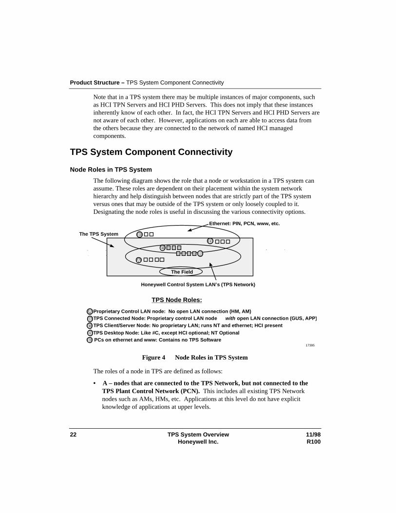
Node Roles in TPS System
The following diagram shows the role that a node or workstation in a TPS system canassume. These roles are dependent on their placement within the system networkhierarchy and help distinguish between nodes that are strictly part of the TPS systemversus ones that may be outside of the TPS system or only loosely coupled to it.Designating the node roles is useful in discussing the various connectivity options.
Ethernet: PIN, PCN, www, etc.
Honeywell Control System LAN’s (TPS Network)
The TPS System
The Field
AB
CD
E
PCs on ethernet and www: Contains no TPS SoftwareTPS Desktop Node: Like #C, except HCI optional; NT Optional
TPS Client/Server Node: No proprietary LAN; runs NT and ethernet; HCI presentTPS Connected Node: Proprietary control LAN node with open LAN connection (GUS, APP )Proprietary Control LAN node: No open LAN connection (HM, AM)
TPS Node Roles:
EDCB
A
17395
Figure 4 Node Roles in TPS System
The roles of a node in TPS are defined as follows:
• A – nodes that are connected to the TPS Network, but not connected to theTPS Plant Control Network (PCN). This includes all existing TPS Networknodes such as AMs, HMs, etc. Applications at this level do not have explicitknowledge of applications at upper levels.
Product Structure – TPS System Component Connectivity
11/98 TPS System Overview 23R100 Honeywell Inc.
• B – the TPS PCN-connected node with direct TPS Network connection. Thisincludes TPS nodes that are on the PCN and are also connected to a TPS Networkthrough an LCNP board in their physical node (e.g., GUS, APP). Access from thesecomponents to the local TPS Network is possible without dependence on the PCN.The components in these nodes also have access to data on the PCN (including otherTPNs) by addressing the appropriate PCN component through HCI.
• C – TPS PCN-connected node without an LCNP board for direct connection toa TPS Network. Data on the PCN is accessible to these nodes, and data on TPSNetworks is accessible by addressing a data server that is connected to the desiredTPS Network, i.e., functionality is the same as for Level B, but without a local TPSNetwork.
• D – PIN-connected node with TPS Software. Here there are actually two levelsof connection, depending on the specific system configuration.
− Most of the Level C functions execute where they can be directly connected tothe PCN for performance and system control needs. If the physical networklayout precludes this, they can be configured to run on nodes that are on thesame subnet with other nodes in that TPS system. A client at this level can bepart of the TPS domain (though not required) and communicate to HCI managedcomponents.
− Applications at the Plant Intranet level, such as those running under theUniformance Desktop (but not limited to these) are set up to connect to a PHDserver rather than to connect directly to a TPN data server. This avoids havingthis load affect TPN performance. There are two methods to make thisconnection. The first is with a direct connection to PHD (through a network thatis separate from the PCN). The second method is a Plant Intranet to PCNconnection that allows PIN applications to connect to the HCI PHD Serverthrough the PCN (the same route that is used by User Applications and GUS).
• E – No TPS System Software. While not actually a TPS node, this role is includedfor completeness and describes all nodes on the PIN that do not contain TPSsoftware or communicate to a TPS system.
Product Structure – TPS System Component Connectivity
24 TPS System Overview 11/98Honeywell Inc. R100
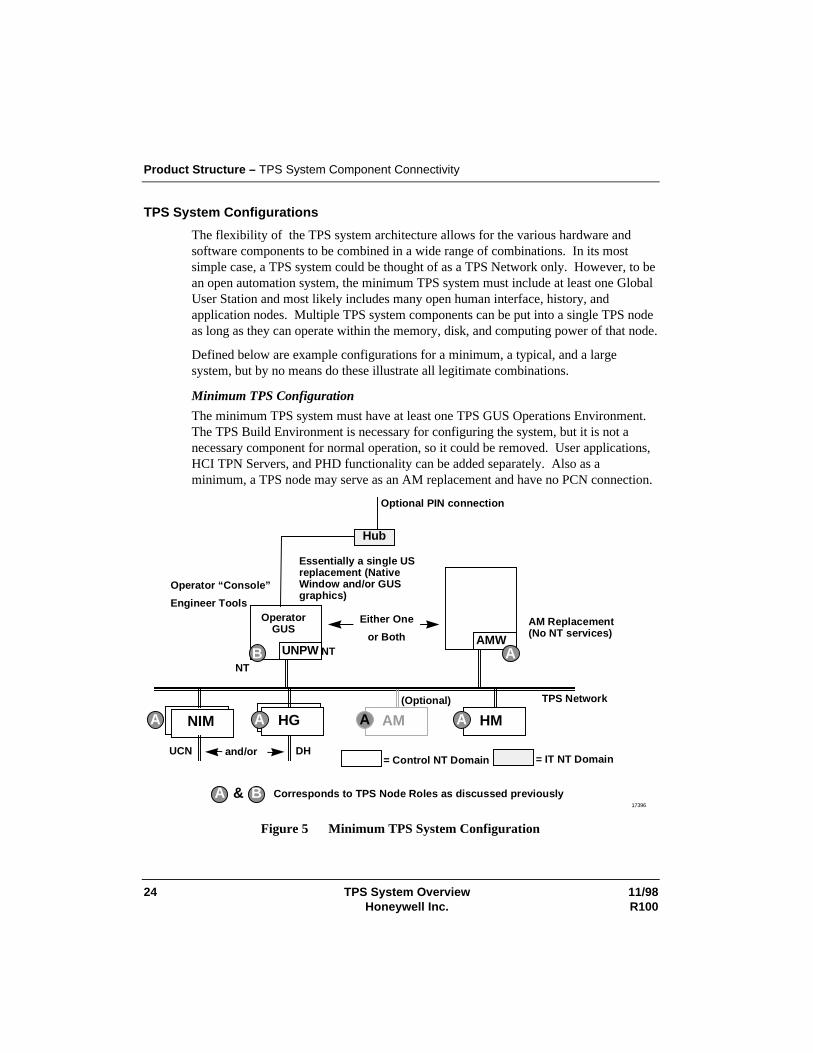
TPS System Configurations
The flexibility of the TPS system architecture allows for the various hardware andsoftware components to be combined in a wide range of combinations. In its mostsimple case, a TPS system could be thought of as a TPS Network only. However, to bean open automation system, the minimum TPS system must include at least one GlobalUser Station and most likely includes many open human interface, history, andapplication nodes. Multiple TPS system components can be put into a single TPS nodeas long as they can operate within the memory, disk, and computing power of that node.
Defined below are example configurations for a minimum, a typical, and a largesystem, but by no means do these illustrate all legitimate combinations.
Minimum TPS Configuration
The minimum TPS system must have at least one TPS GUS Operations Environment.The TPS Build Environment is necessary for configuring the system, but it is not anecessary component for normal operation, so it could be removed. User applications,HCI TPN Servers, and PHD functionality can be added separately. Also as aminimum, a TPS node may serve as an AM replacement and have no PCN connection.
NIM
UCN
TPS Network
HG
DH
AM HM
NT
OperatorGUS
UNPW NT
A
B
A A A
and/or= Control NT Domain = IT NT Domain
Operator “Console”
Engineer Tools
Hub
Optional PIN connection
(Optional)
Essentially a single USreplacement (NativeWindow and/or GUSgraphics)
AMW
AM Replacement(No NT services)
A Corresponds to TPS Node Roles as discussed previouslyB&
Either One
or Both
A
17396
Figure 5 Minimum TPS System Configuration
Product Structure – TPS System Component Connectivity
11/98 TPS System Overview 25R100 Honeywell Inc.
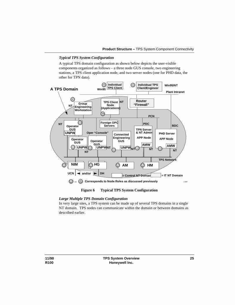
Typical TPS System Configuration
A typical TPS domain configuration as shown below depicts the user-visiblecomponents organized as follows – a three node GUS console, two engineeringstations, a TPS client application node, and two server nodes (one for PHD data, theother for TPN data).
NIM
UCN
TPS Network
DH
AM HM
OperatorGUS
UNPWNT
OperatorGUS
UNPWNT
OperatorGUS
UNPW
UNPW
NT
NT
PCN
NTTPS ClientNode
(Applications)
Plant IntranetWin95
IndividualTPS Client
D
C
B
A
BB B B
A A A
ConnectedEngineering
GUS
and/or
Win95/NTIndividual TPSClient/Engineer
D
PHD Server
AMW
= Control NT Domain = IT NT Domain
Oper “Console”
PDC
NT NT
TPN Server& NT Admin
BAMW
A TPS Domain
BDC
A Corresponds to Node Roles as discussed previouslyB.. D
APP Node APP Node
HG
Router“Firewall”
Foreign OPCServers
GroupEngineeringWorkstation
NT
D
17397
Figure 6 Typical TPS System Configuration
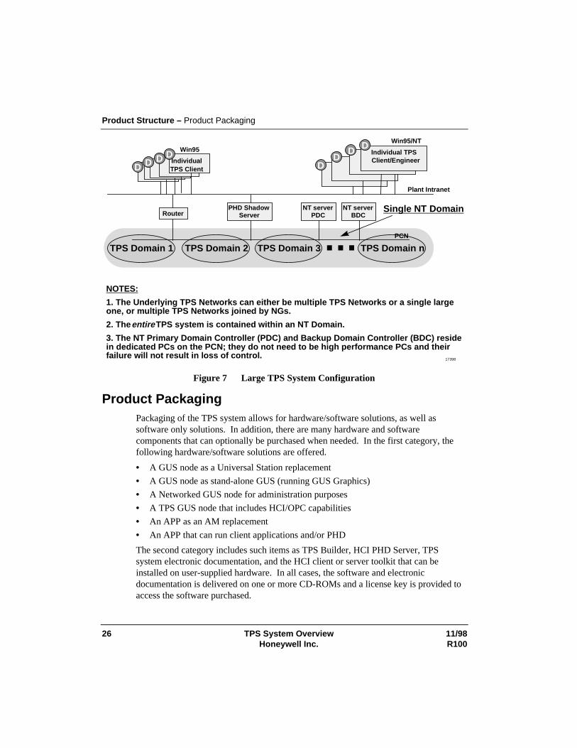
Large Multiple TPS Domain Configuration In very large sites, a TPS system can be made up of several TPS domains in a singleNT domain. TPS nodes can communicate within the domain or between domains asdescribed earlier.
Product Structure – Product Packaging
26 TPS System Overview 11/98Honeywell Inc. R100
Plant Intranet
DD D D IndividualTPS Client
D D
TPS Domain 1
PHD ShadowServer
TPS Domain 2 TPS Domain 3 TPS Domain n…NOTES:
1. The Underlying TPS Networks can either be multiple TPS Networks or a single largeone, or multiple TPS Networks joined by NGs.
2. The entire TPS system is contained within an NT Domain.
3. The NT Primary Domain Controller (PDC) and Backup Domain Controller (BDC) residein dedicated PCs on the PCN; they do not need to be high performance PCs and theirfailure will not result in loss of control.
Win95Win95/NT
Single NT Domain
PCN
RouterNT server
PDCNT server
BDC
Client/EngineerIndividual TPS
DD
17398
Figure 7 Large TPS System Configuration
Product Packaging Packaging of the TPS system allows for hardware/software solutions, as well assoftware only solutions. In addition, there are many hardware and softwarecomponents that can optionally be purchased when needed. In the first category, thefollowing hardware/software solutions are offered.
• A GUS node as a Universal Station replacement
• A GUS node as stand-alone GUS (running GUS Graphics)
• A Networked GUS node for administration purposes
• A TPS GUS node that includes HCI/OPC capabilities
• An APP as an AM replacement
• An APP that can run client applications and/or PHD
The second category includes such items as TPS Builder, HCI PHD Server, TPSsystem electronic documentation, and the HCI client or server toolkit that can beinstalled on user-supplied hardware. In all cases, the software and electronicdocumentation is delivered on one or more CD-ROMs and a license key is provided toaccess the software purchased.
11/98 TPS System Overview 27R100 Honeywell Inc.
Product Overview
Hardware The hardware platform for the TPS-connected nodes (TPS node Role - B) iscommodity workstation hardware running Windows NT. Open platforms for TPSsystem are based on the Intel Pentium Pro or Pentium II processors. A range of overallprocessor speeds, memory sizes, cache sizes, and disk size options for each processortype are supported. The recommended open platform size and performance for aspecific TPS system application is determined by that application’s needs.
The minimum hardware configuration supported is that released for GUS 100 MR3 andall TPS functions operate with that configuration.
Maximum configurations are set by those reasonably available from the approvedplatform vendors, which offer platforms of the supported processor types.
Operating Specifications: Environmental specifications (e.g., operating temperature,shock and vibration tolerance, etc.) are those offered commercially by the openplatform suppliers. (See “TPS System Ready Consoles” below.)
CE Mark: All open platforms conform to Commercial (Class B) CE Markspecifications. Honeywell-supplied platform packages (EZ-Console, Z-Console,Classic, or Cabinet mount configurations) conform to Industrial (Class A) CE MarkSpecifications.
Keyboards: Deskside platforms are available with three keyboard options:Commercial AT101, Industrial CE Mark AT101, and the Desktop Integrated Keyboardwhich is also industrial CE Mark.
Console mounted platforms are offered with the Console Integrated Keyboard or theOperator Keyboard/Engineering Keyboard (industrial AT101 as above) and OperatorEntry Panel (OEP) offerings from previous TPS Network products.
LCNP4
The LCN coprocessor allows the data connection to the TPS Network infrastructureand the operation of TPS Network software personalities. The LCNP4 is a high-performance version of the LCNP offered on previous GUS releases. It is based on theMotorola MC68040 processor and has functionality and performance similar to theK4LCN. The LCNP4 differs in functionality from the LCNP in the following ways.
Product Overview – Global User Station (GUS)
28 TPS System Overview 11/98Honeywell Inc. R100
• Performance: TPS Network-based performance of the LCNP4 is similar to theK4LCN. The LCNP was similar in performance to the K2LCN.
• Memory Size: The LCNP4 has a memory size of 16 megawords (32 megabytes).The LCNP is limited to 8 megawords.
• Independent Reset: The LCNP4 allows an independent reset of the NT and RNOSprocessors. This allows the TPS Network personalities (e.g., the AM) to “ridethrough” an NT reset.
Both the LCNP4 and older LCNP are available and continue to be valid hosts for GUS.For APP, only LCNP4 is valid.
TPS System Ready Consoles
TPS system platforms are offered in deskside, EZ-Console, Z-Console, and ClassicConsole mount furniture, or TPS Network Cabinet mount. Deskside and desktopversions are as supplied by the commercial suppliers.
A CRT and keyboard is required for all TPS nodes. These can be the keyboard andCRT built into the consoles (as in GUS), or keyboards and CRTs that rest on worksurfaces or adjacent tables for non-GUS TPS nodes mounted in consoles. Systems thatrequire Industrial (Class A) CE-Mark use Industrial CE versions of the keyboard andCRT.
Color monitors from 17-inch to –21-inch diagonal sizes are available for the deskside-packaged units. Deskside touchscreens are offered in 21-inch diagonal size only. Z-Console mounted monitors are 21-inch only with touchscreen. Classic Consoleversions use a 19-inch multi-synch monitor.
Both industrial (Class A) and commercial (Class B) CE Mark are met in the EZ-Console, Z-Console, Classic Console, and Cabinet packaging options (with appropriateperipherals). Deskside TPS nodes only meet Commercial (Class B) CE Markrequirements.
Intel-Based Platforms
Intel-based platforms are supported and are based on the PentiumPro 200 or thePentium II as the processor engine with ECC (error correction code) data integrity onboth main memory and cache. Platforms can be used in all mounting/furniture options.
Global User Station (GUS) GUS is available in either a deskside platform or in Classic, Z-Console, and EZ-Console furniture. Each GUS connects to the TPS Network through the LCNP orLCNP4 board. Each GUS also has a built-in Ethernet connection that can be
Product Overview – Global User Station (GUS)
11/98 TPS System Overview 29R100 Honeywell Inc.
configured for either 10BaseT or 100BaseT use. This allows a GUS to be connected toan existing network or to be set up with the proper hub, router etc., for a new network.GUS software functions are packaged separately and can be combined to meet functionneeds on a station-by-station basis.
Base System
The Base System software is the only mandatory software function. It must accompanyall TPS Network-connected GUS stations. This software performs the data accessbetween the TPS Network and GUS. Its second main function is to show one UniversalStation display through the "Native Window." This Native Window provides thefollowing TPS Network functions.
• Console-Based Alarm Management
• Cross Screen Display Invocation
• Standard Display Access (Group, Detail, Alarm Summary, etc.)
• Access to all Universal Station tools (DEB, NCF, etc.)
• Shared PC Printers and Disks
The Base System is not needed when the Display Builder is used to create newdisplays, but is needed to test them.
Multiple Displays
The Base System allows viewing of one GUS Display at a time concurrent with theNative Window.
GUS Display Server (local TPN Data)
GUS Display Server contains the components necessary to access TPN data andfunctions required to operate a process and support on-line display building.
HCI Named Data Access
GUS Displays can access HCI managed components in two ways: through OLEAutomation and through named data access (e.g., “SRV1.A100.PV”). Display authorsmay script GUS displays to invoke any OLE automation interface or named data accessto read or write HCI server data.
GUS Utilizing IOMaps
An IOMap is an intermediary HCI/OPC Server that runs “in-process” to the client (seeApplication I/O below). Therefore, an IOMap may be accessed using OLE Automation
Product Overview – Global User Station (GUS)
30 TPS System Overview 11/98Honeywell Inc. R100
calls in GUS scripts or using named data access in GUS scripts and variableexpressions.
IOMaps are the primary method of redirecting data access among HCI servers (notHOPC servers) in a GUS display. As an example, a user may create a GUS displayrepresenting a furnace pass and referencing generic data through an IOMap. Bychanging the data source (i.e., IOMap), the furnace pass display may be reused torepresent Furnace Pass 1, Furnace Pass 2, etc.
GUS Standard Displays
Active X controls that emulate the functionality and performance of the standard USdisplays are available and can be inserted in a GUS graphic. These include
• GUS Alarm Summary Control
• GUS Message Summary Control
In addition, a GUS Group display application is available that emulates the standard USgroup display. This display conforms to the standard Group Definition as configured inthe Area Database.
SafeView
SafeView is a runtime option that lets the operator work in a windowed environment,yet maintain a predictable, repeatable, safe interface to the plant. With SafeView,engineers can divide each screen into regions, and designate what type of display orapplication goes into each region. They can also decide if displays in each region aremovable and sizable. SafeView can also protect the plant window from being overlaidby other applications. Many SafeView configurations can be built, but only one can beactive at any given time.
Reusable Components
In addition to the Active X controls listed above, an additional set of reusablecomponents is available with GUS. These include the following.
• The GUS Faceplate which is an Active X control presenting the full functionality ofone of the slots in a US group display
• The Honeywell Change Zone which is an embedded picture with the equivalentfunctionality of the US Change Zone
TPSDDE
TPSDDE lets users access TPN data and send it to applications running on GUS, or upto a plant network for use by other DDE compliant applications.
Product Overview – Uniformance Desktop
11/98 TPS System Overview 31R100 Honeywell Inc.
Uniformance Desktop The Uniformance Desktop is a set of tools and enablers that provide easy access tohistory data using PCs. Simple, quick access to high-resolution history data lets theuser run analysis and reporting applications that can enhance plant decision making.Desktop components offer easy and flexible access to this data. The UniformanceDesktop includes Process Trend, TDC Viewer, an example Excel spreadsheet withembedded history calls, Visual PHD, and several VB examples.
Process Trend
Process Trend allows a user to trend process history data. A user can easily manipulatethe time and value scroll bars to scan through data and zoom in for more detailedanalysis. Each trace tag can be independently scrolled, so the user can visuallycompare tags on a different time basis. The trend picture can be copied to the clipboardfor import into a document, or the data behind the trend copied into a file for importinginto a tool such as Microsoft Excel for more detailed analysis. A hairline cursor givesthe user an exact value for each trace at the point in time where the cursor is placed.
Multiple tags (up to eight) can be plotted in the same window, plus multiple trendwindows can be opened. Each trace in each window can be manipulatedindependently. For example, the time scale can be offset to allow comparison of thecurrent shift’s results with a previous shift. The value scale can also be different foreach tag.
Conditional Query
Process Trend provides the user with the capability of constructing a conditional query.After submitting the conditional query, the user receives notification of a collection oftime intervals where the condition is satisfied. This user is then able to plot data forany of the identified time intervals.
Display Suites
Process Trend users are able to open and save a suite (collection) of up to five ProcessTrend plots and/or up to 10 analysis windows. The window orientation that appearswhen the suite is opened is the same as when the suite was previously saved.
TDC Viewer
The TDC Viewer allows the user to look at Universal Station schematics on a PC. Theuser can view the display at current time or at any time in the past, or replay historydata through the display at a controlled rate. Displays are view-only. Many schematicscan be viewed at the same time without placing a load on the TPS Network controlsystem, since all data comes from PHD. TDC Viewer uses displays withoutmodification, once uploaded from the History Module to the user’s PC.
Product Overview – Uniformance Desktop
32 TPS System Overview 11/98Honeywell Inc. R100
Note: TDC Viewer is a viewing tool for data contained in the history database. TDCViewer does not incorporate all of the functions of an active schematic on a UniversalStation (US) or a Native Window GUS. The following functions are not available withTDC Viewer.
• Local tags accessible on a US station (i.e., ACKSTAT)
• Trends within schematics
• Tag indirection
Scheduler
This utility is a Microsoft Windows-based application scheduler. A user can scheduleany Microsoft Windows program to run periodically or at a specified time. Forexample, a daily report based on the Microsoft Access report writer using data fromPHD can be initiated by the scheduler. A user can view the applications to bescheduled, applications currently running, and the status of applications that wereactivated by the scheduler. Applications can also be scheduled to run sequentially sothat, for example, the daily report does not run until the shift report has completedsuccessfully.
Visual PHD
Visual PHD consists of an OLE Automation Server and Active X Objects for datareporting and application development. The objects consist of a Data control, Textcontrol, Bar control, Graph control, TagText control, and TagPicker control. Theseobjects can be embedded in Visual Basic and Microsoft Office applications to createcustom information applications for a particular plant site. For example, a bit mapdepicting an overhead view of the plant can be imported to Visual Basic, then the OLEobjects can be embedded on the picture to create an information schematic. Thisdisplay can be saved as an executable and e-mailed to anyone in the company.
The Visual PHD Active-X components operate within standard OLE serverapplications. These include Visual Basic 5.0 and the suite of Microsoft Office 97applications.
Example Excel Spreadsheet
Visual PHD makes it easy to develop custom Excel applications that require processdata. An example spreadsheet is included that can be modified by a user to meet mostneeds for process data analysis using Excel. It is also easy to create a conditional queryof history data using this spreadsheet. The example spreadsheets are compatible withExcel 97 and Excel 95.
Product Overview – Process History Database (PHD)
11/98 TPS System Overview 33R100 Honeywell Inc.
Interactive Query
Interactive Query (IQ) provides an easy-to-use mechanism for transferring history datafrom PHD to Microsoft Excel. One powerful aspect of Interactive Query is the tool’suser interface, which allows interactive selection of plant data. Once a request is made,it allows the user to control the flow of data to Excel through its control windowinterface. The user can request a large amount of history data and then “replay” thatinformation by stepping through samples at the selected rate. Also available is a“refresh” mode, which automatically re-executes a query periodically, to support a livetrend, for example.
Dynamic Query (DQ) and Microsoft Query (MQ)
Dynamic Query also history retrieval requests are to be constructed by references toother cells in the Excel spreadsheet. The 128-character limitation on history retrievalrequests can be bypassed. A mechanism is provided to place all history retrieval resultsinto an Excel spreadsheet without requiring the user to identify a fixed region beforeissuing the request.
The user is also provided with the ability to manipulate the result set from a historyretrieval request in Microsoft Query.
History Browser
The History Browser provides an easy-to-use mechanism for transferring history datafrom PHD to Microsoft Access. The result set is placed in a table in a MicrosoftAccess database, where it can be viewed, exported, reported on, or integrated with datafrom other sources.
Process History Database (PHD) Process History Database (PHD) is the process data historian of Honeywell’s plant-wide TotalPlant Solution system. PHD collects, integrates, and maintains a long-termhistory of real-time continuous and discrete production, process performance, andprocess-related data. The PHD Server can collect data from the TPS Network andother data sources. Some key PHD features follow.
Multiple Data Types Supported
PHD supports real, integer, binary, and alphanumeric (text) data types integratedseamlessly in one database. PHD supports a 32-character tag name. The tag name maybe the same or different than the tag name used by the source system. For consistency,it is recommended that they be the same.
Product Overview – Process History Database (PHD)
34 TPS System Overview 11/98Honeywell Inc. R100
Tag Configuration
PHD provides the ability to define new or modify existing tags without having torebuild the database or shut the system down. The number of tags that can be scannedis dependent only on the capability of the processor and the source of the data. PHDalso provides a powerful utility to automatically generate the PHD tag parameters andtheir reference attributes.
Class Tag Configuration
PHD tag definition supports the use of “class tags” that other tags may reference astheir parent. Any tag attributes that are not specifically defined for a tag are inheritedfrom its parent class tag. A class tag may in turn inherit values from another class tag.If a class tag attribute is modified, any tags that inherit the attribute dynamically inheritthe change. This permits the system to be configured with a set of intelligent defaulttag attributes. This feature simplifies tag definition and maintenance because thebehavior of entire classes of tags can be altered after the tags are defined, simply bymodifying the parent class tag.
Data Retrieval Independent of Data Collection
Applications may query data for times that are independent of point scan rates orstorage intervals. Accurate measurements for operations transactions can then bedetermined regardless of the transaction times or duration.
Time Weighted Data Reductions
Reductions, which include min, max, delta, mean, linear regression, running average,and standard deviation are performed on a time-weighted basis vs. sample basis.These reductions return both a reduction value and a composite confidence factor basedon the reliability of the source data.
Automatic Engineering Unit Conversions
PHD provides standard engineering unit conversions between absolute values, rates,and accelerations. For example, a flow that is measured in barrels/day can be requestedas gallons/hour. Data conversion to and from metric units is also supported. Thisallows users and applications to request information for a measurement in the unitsrequired without having to build conversion functions into the various user tools andapplications.
Virtual Calculations
PHD provides the capability to perform a calculation to handle situations such as whenlab physical properties are not available for several hours after the sample time. PHD
Product Overview – Process History Database (PHD)
11/98 TPS System Overview 35R100 Honeywell Inc.
also provides the ability to evaluate logical time-based inferences of process data orother manual inputs from operator logs. For example, “what was the change in valueover the last 5 minutes, hour, etc.?” and “did this change exceed a logic operatingthreshold?”
PHD returns a calculated result along with the calculated confidence for the resultbased on the reliability of the tags referenced by the calculation.
Conditional Data Search and Retrieval
PHD provides conditional processing logic for retrieval of data using a conditionalstatement. PHD provides the ability to review history between a start and end date andexamine the values based on conditional expressions.
System Capacity
The resolution of history data and length of history retention is configurable. Typically,a customer keeps high-resolution (scan rate) data online for 2 to 3 years or longer.
Exception Condition Interfaces
The exception condition interface may be linked with any standard RDI polled-typeRDI in order to implement scanning controlled by exception conditions. The exceptioncondition interface generates “exception” data for a group of real-time tags by pollingthem when data for these tags is required, according to the current conditions. Theexception condition interface must be linked with an RDI polled interface in order tofunction. This can be an interface to a real-time system, or a PHD-to-PHD interfacerunning in polled mode.
Automated Backup
PHD provides the ability to perform an on-line backup of the history database with nodata loss. PHD also provides the ability to create an archive that may be removed totape and later restored without having to shut the system down.
Data Compression
PHD provides an innovative data elimination compression technique. Since data isrepresented as a series of virtual linear segments between points, intermediate valuescan be eliminated if they can be estimated to within an error tolerance specified for thetag.
Product Overview – Application Program Execution
36 TPS System Overview 11/98Honeywell Inc. R100
HCI PHD Server
The HCI PHD Server provides OPC client access to current values for variables storedin the process history database. It provides both read and write capability for a singlevariable or a list of variables. Values written to PHD may be forwarded to the dataowner.
TPN Event Journal Collection and Storage
PHD collects journals from the event journals on the TPS Network History Module(HM) and inserts the event messages into tables in a relational database to providerelational access to this information. All of the HM journals (sequence of events,operator changes, alarms, etc.) are available from PC applications.
Journals are messages that describe events that occurred on a control system.Typically, these event messages are not available to higher level systems. Manyadvanced applications need this information.
The TPS Network journals are captured from TPS Networks connected to TPS nodes,or Alpha AXPs (using CM50s). The types of journals that are collected, and thecollection (polling) frequency are configurable.
Application Program Execution While GUS nodes are intended to provide human interface capability; in general,applications, particularly permanently running applications, should execute in separateTPS nodes, independent of the GUS nodes. This allows view and operation frommultiple GUSs, and it assures that the CPU and other resource load for applicationexecution and for data accessing do not compete with operator priorities at GUSstations. The APP is designed to provide a good platform for these applications,independent of GUS operation. It has a connection to a TPN (the LCNP/LCNP4 board)using an HCI TPN Server. In addition, it can optionally have a CL Server, PHD withHCI PHD Server, and IOMap Server capability.
Product Overview – Application Program Execution
11/98 TPS System Overview 37R100 Honeywell Inc.
NT Client Applications
There are several mechanisms for executing application processes in NT. One is toinvoke the client as an "Interactive Process." Another is to setup an automatic loginand start the application through the startup group and a third way is invoke the clientas a “Service Process” with the User ID set up by the system administrator. In anycase, the application ultimately runs under a process that acts as a client to the dataserver and the TPS system.
CL Server
The CL Server provides a way to launch and schedule NT applications on the APPfrom CL programs running in the TPN Application Module personality loaded on theLCNP4 board.
Application Scheduling
Scheduling for those applications that require it can be accomplished through thestandard AM point-processing mechanism. The CL/AM extensions of the AMpersonality of the APP provide the ability for a CL/AM program to trigger a newinstance of an NT application that starts, executes, and completes. The CL/AMprogram waits until the execution of the application has completed before continuing.On each activation, the CL program may pass an invocation string to the program beingactivated. This can be used to communicate the reason for activation.
Only background CL programs may be used to initiate application programs. Multipleapplications, activated from a single AM point, are executed serially, the order ofexecution determined by the CL insertion point order on the AM point.
Application Management
The CL Server provides management capability limited to the installation of singleapplications within the APP. It assists in the management of executables initiatedthrough the CL/AM extensions defined above. It focuses on the following primaryfunctions.
• Install/deinstall applications which includes registration with CL Server
• View summary and state of installed applications through the CL Server specificportion of the TPS Status Display, but not through HCI named data
• Aborting of selected applications through the CL Server specific portion of the TPSStatus Display, but not through HCI named data
Product Overview – Application Program Execution
38 TPS System Overview 11/98Honeywell Inc. R100
Application I/O
Current value I/O interfaces are provided as HCI/OPC interfaces. This includes boththe “Custom” C++ interfaces and the OLE Automation interfaces.
HCI TPN Server
The HCI TPN Server provides OPC client access to TPN data and also supports HCIoptional interfaces. It provides both read and write capability for a single variable or alist of variables, as well as asynchronous requests.
Application access security is provided through the TPS Security Model that isdescribed later. Applications can specify a TPN key level for their TPN accesses. Thiskey level is checked against Permissions on a proxy file previously setup by theadministrator. This proxy file mechanism is used to control the ability to change thesekey levels such that they can be used for setting “program” or “continuous control”access levels.
IOMap Server
In addition to the ability to access an HCI component directly using the HCI/OPCCustom or Automation interfaces, a client application can use an IOMap server. AnIOMap server is an intermediary HCI/OPC server that runs “in-process” to the client.It allows IOMaps to be loaded which, when accessed through generic item names, canbe redirected through the IOMap configuration to any external HCI/OPC server. Thisallows the application code to use generic names such that the actual I/O destinationscan be determined at build time or at runtime. Some features of IOMaps include thefollowing.
• Ability for IOMaps to be built by the TPS Builder
• Ability for IOMaps be built and modified by executing applications
• Ability to access multiple ultimate HCI/OPC servers (also known as scatter/gather)
• Test value insertion capability
• Ability for IOMaps to be used with GUS Displays as well as for NT applicationprograms.
PHD Use to Reduce TPN Loading
As discussed in the earlier section on PHD, current values of PHD are accessiblethrough an HCI PHD server. As such, PHD, through HCI and IOMaps is an alternativefor fetching and storing values. PHD can be and often is used with applications in thefollowing ways.
• Tagnames from the source system are configured in PHD, scanned by PHDindependently of applications, and accessed through HCI, perhaps using IOMaps.
Product Overview – Event Annunciation and Journal Entries
11/98 TPS System Overview 39R100 Honeywell Inc.
If the same value is used by multiple applications or is also historized, this usagecould significantly reduce the load on the TPN as compared to direct accesses tothe TPN Server.
• PHD Auxiliary Tags are used to store the state of the application, which is usefulfor communication with other applications or for operator access through GUS.This is an alternative to storing the data on the TPN (for example, in AM customdata segments), which, again, yields significantly reduced TPN loading.
Event Annunciation and Journal Entries
TPS Network Process Alarms and Messages
Process alarms and messages from the TPS Network are presented on the NativeWindow and the Integrated Keyboard (IKB) exactly as they are on the TPS Network.In addition TPS Network alarms and messages are available within GUS displays asdiscussed in the previous section on GUS.
TPS Network System Status
TPS Network System status (including LCN, UCN, Data Hiway, module, and boxstatus) is presented on the Native Window and the Integrated Keyboard exactly as theyare on the TPN. For system level operations, such as directing node startups,checkpointing, etc., the operator must use the Native Window.
Journals of TPS Network Events
HM Journals are available exactly as they are on the TPN, including data retrievalthrough the Native Window. In addition, PHD can be configured to collect HMjournals and store them into relational tables, where the information is availablethrough various relational query tools.
Application Alarms
NT applications that need to present application conditions such as process alarms tothe operator can use AM facilities (e.g., switch data point) to create custom alarms.
NT Event Log
Other events of interest are captured in the NT Event Log, on each TPS node. They areviewed through NT facilities at the node of origination of the event. These eventsinclude such things as the following.
• Log-in/log-out
Product Overview – System Management
40 TPS System Overview 11/98Honeywell Inc. R100
• System configuration changes
• System software errors
• Application errors that are directed to the TPS system event log interface
System Management
Persistent Storage Maintenance (backup and recovery)
Backup Exec for Windows NT from Seagate Software (formerly Arcada) is suggestedfor use by customers and is provided with the system when a tape drive is purchased.
PHD handles backup and restore independent of other TPS system components.Backup of PHD requires backing up both the reference data and the history data.
The TPS Builder runs on top of MS Access. The user must be able to do databasebackup and reload, which requires a level of database administration skills.
Journal Display and Maintenance
Journal maintenance is the act of clearing journal entries or saving journal files to abackup media. The NT Event Viewer can be configured for the size of the journal fileand for the policy for keeping or discarding events when the log is full. In addition, thelog file can be archived and retrieved later for viewing using the Event Viewer. TheAdministrator is responsible for these maintenance policies.
PHD collects TPN Events and journals them into relational database tables. To viewthese journals, any tools that can view relational database tables (e.g., MS Access) canbe used. Since the event journals are stored in relational tables, queries can be made tosearch for desired events. The Event Journal tables must be maintained through therelational database maintenance tools.
TPS System Status Display
The TPS System Status Display shows the states of the TPS nodes configured into thisTPS domain, and the states of the HCI managed components on them. Node and HCImanaged component failures are shown here. Startups and shutdowns can becommanded from this display.
Performance and Network Management
Performance and Network Management provide a means of detecting, correcting, andanalyzing processing and communication inefficiencies and faults. The tools providedare a collection of existing NT and TPS Network standard capabilities, as well asoptional tools provided by Network Services. These include the following.
Product Overview – System Management
11/98 TPS System Overview 41R100 Honeywell Inc.
• Standard NT Performance Monitor tool
• Standard NT Process View tool
• Standard TPS Network CPU utilization displays
Security Management
A default security policy that predefines NT domain user groups is shipped with eachTPS system. The following are the default NT domain user groups.
• Administrators
• TPS Administrators
• Operators
• Supervisors
• Engineers
• Program Users
• Continuous Control Users
• Point Builders
• Intimate Users
• View Only Users
• Backup Operators
• Replicator
Customers can tailor their own specific security policies using the existing NT securityadministration tools.
System Configuration
System configuration provides the mechanisms for configuring a TPS system andincludes the configuration of the following.
• TPS Domain and TPS System Replication attributes
• HCI Managed Components (i.e., HCI TPN Server, HCI PHD Server, etc.)
• Attributes of HCI Managed Components
− Performance Parameters and Policies (throttling, etc.)
• Time Synchronization
Product Overview – Build Environment
42 TPS System Overview 11/98Honeywell Inc. R100
The system administrator uses a stand-alone TPS system configuration tool from whichconfiguration of all HCI managed components can be initiated. This tool is aninteractive program that presents the administrator with an interactive tab-dialog styleconfiguration sheets for examining and setting the configuration. From this tool bothlocal and remote TPS nodes and HCI managed components can be configured from asingle TPS node. TPS Network node configuration is still done using the NativeWindow connected to the chosen TPS Network.
Build Environment The TPS Engineering Environment provides tools for the following activities.
• Control strategy building (ranging from TPN devices to IOMaps)
• PHD configuration
• US Display Translator
• GUS display building
• SafeView workspace building
• HCI Client development
• HCI Server development
TPS Builder
TPS Builder is the foundation for a common build environment and single pointconfiguration for the various aspects of the control solution. The TPS Builder providesthe configuration capability for the following TPN nodes: PM, APM, HPM, AM,Hiway Boxes, LM, FSC, Enhanced Program Logic Controller Gateway, and ComputerGateway.
It also supports linking and embedding of any OLE compliant documents into a controldrawing and creating GUS Displays from control drawings. TPS Builder templates,libraries, strategies, and projects allow application components to be grouped togetherin order to construct an entire TPS system application package. Initially, the definitionof a common I/O "mapping" mechanism (IOMap) is provided. The IOMap conceptsupports the development of common TPS system application components that canexecute within various TPS system components.
PHD Configuration
The PHD Reference Database defines what PHD collects, how often, and how it isstored. This is also where the definition of the collection groups is stored. Configuringthis database is the first step during the implementation of PHD. All points, variables,
Product Overview – Build Environment
11/98 TPS System Overview 43R100 Honeywell Inc.
and data sources need to be defined. Each variable is assigned to a collection group orgroups and the description, engineering units, range, and compression parameters,among others, are defined.
TotalPlant Information is a separate tool and is used by the administrator to set-up theReference Database, which determines the operation of PHD. To alleviate the task ofindividually creating each variable to be collected, a Bulk Loader tool is available withPHD. This tool imports the TPN point and parameter information and sets upappropriate tables in the Reference Database. A user can set up defaults and manuallytailor the configuration during the bulk load process. Of course, any bulk-loadedvariables can be modified later.
Display Translator
Display Translator translates existing US schematics to GUS displays. While theDisplay Translator does not translate 100% of a display (for example, Overlays andChange Zones are not translated), it does a good job of translating TPS Networksubpictures and associated code into GUS Display pictures and script code.
Display Builder
Display Builder is the easy-to-use graphical tool that builds custom GUS operatingdisplays. Through Display Builder, an engineer can create display backgrounds,animation, and other active functions that graphically show plant data or initiateactions. The displays can be linked to points/parameters that represent sensors andcontrollers in your plant. Display Builder is menu-based and it lets you create displaysthat have a rainbow of colors, better animation, 3D look, and photographs. It alsoallows you to embed OLE control objects and applications directly into a display.
This component also includes the following.
• Display Migrator – Providing the ability to migrate GUS picture files to newerrevisions
• Display Validator – Providing the ability to perform validation on sets of displayfiles
SafeView Editor
The SafeView Editor provides both a textual and graphical editor for creating SafeViewworkspaces.
HCI Client Toolkit
The HCI Client Toolkit provides guidelines and interfaces, as well as header files andlibraries necessary for compiling and linking clients. This includes both OPC standard
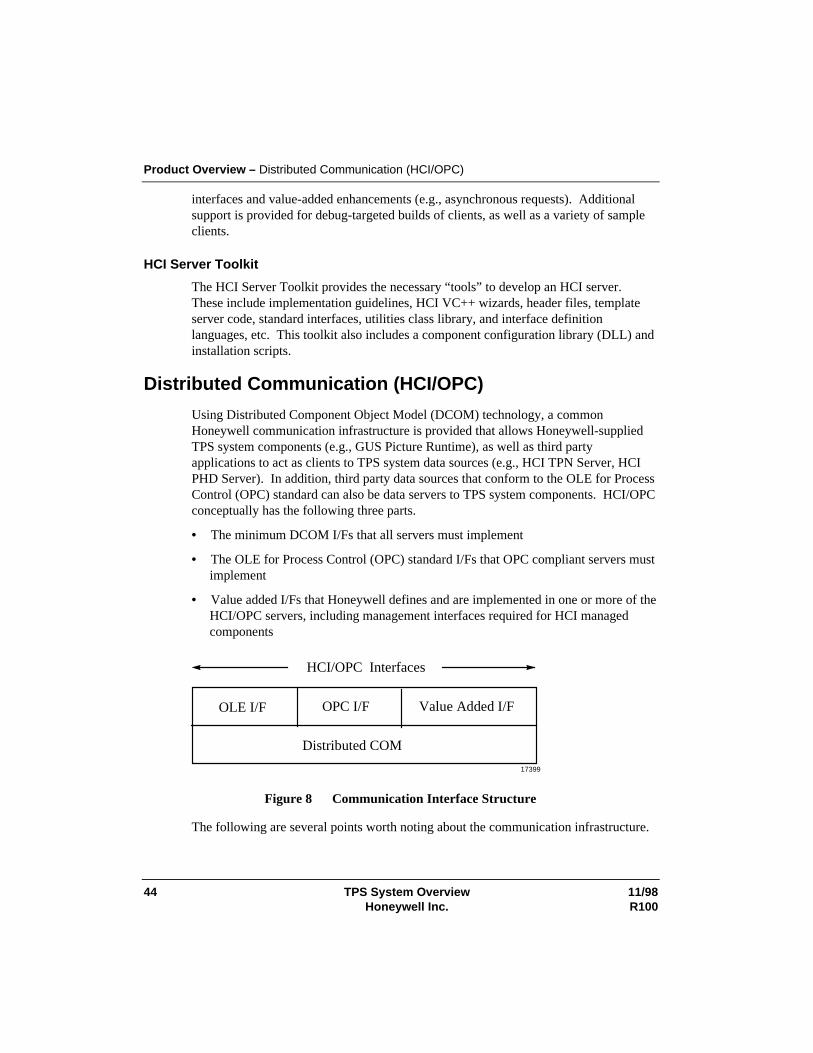
Product Overview – Distributed Communication (HCI/OPC)
44 TPS System Overview 11/98Honeywell Inc. R100
interfaces and value-added enhancements (e.g., asynchronous requests). Additionalsupport is provided for debug-targeted builds of clients, as well as a variety of sampleclients.
HCI Server Toolkit
The HCI Server Toolkit provides the necessary “tools” to develop an HCI server.These include implementation guidelines, HCI VC++ wizards, header files, templateserver code, standard interfaces, utilities class library, and interface definitionlanguages, etc. This toolkit also includes a component configuration library (DLL) andinstallation scripts.
Distributed Communication (HCI/OPC)
Using Distributed Component Object Model (DCOM) technology, a commonHoneywell communication infrastructure is provided that allows Honeywell-suppliedTPS system components (e.g., GUS Picture Runtime), as well as third partyapplications to act as clients to TPS system data sources (e.g., HCI TPN Server, HCIPHD Server). In addition, third party data sources that conform to the OLE for ProcessControl (OPC) standard can also be data servers to TPS system components. HCI/OPCconceptually has the following three parts.
• The minimum DCOM I/Fs that all servers must implement
• The OLE for Process Control (OPC) standard I/Fs that OPC compliant servers mustimplement
• Value added I/Fs that Honeywell defines and are implemented in one or more of theHCI/OPC servers, including management interfaces required for HCI managedcomponents
Distributed COM
OLE I/F OPC I/F Value Added I/F
HCI/OPC Interfaces
17399
Figure 8 Communication Interface Structure
The following are several points worth noting about the communication infrastructure.
Product Overview – Distributed Communication (HCI/OPC)
11/98 TPS System Overview 45R100 Honeywell Inc.
• All interfaces use DCOM as the underlying distribution mechanism and they are notlayered on top of each other.
• All HCI managed components have a common set of interfaces in addition to theusual DCOM interfaces. These interfaces include functions such as versionidentification, status/instrumentation, and other system management-relatedfunctions.
• Value-added interfaces are provided as needed to support functionality not definedin OPC, as well as to improve robustness.
• HCI clients and servers are arbitrarily distributable. That is, there is no mechanismthat prevents such distribution. As a matter of policy, of course, certain clients andservers may be co-resident.
Value Added Functions and Robustness
Functional and robust enhancements have been added to the standard OPC interfaces.Since DCOM does not directly support timed or prioritized communication requests,the facilities to enable this are provided to HCI/OPC servers (i.e., HCI TPN Server) bythe system infrastructure. In addition, convenience functions are provided to unpackdata as well as for the handling of asynchronous I/O.
A common set of security, caching, and self-registration mechanisms are provided tothe authors of HCI managed components.
HCI/OPC also provides a common mechanism for HCI managed components toperform checkpoints and to support restart from checkpoint. HCI managed componentsare responsible for performing their own checkpoints and restarts, using thismechanism.
TPS System Naming Structure
Data fetched and stored from HCI managed components (i.e., data sources) throughHCI is modeled as a TPS object, which is the TPS extension of the TPN data point.The general form of the name for such an access is
//TPSDomainName/HciComponentName/ServerSpecificName
where
TPSDomainName is the name of the TPS domain – the name space of the set of HCIcomponent names being used. If omitted, the default is the local TPS domain.
HciComponentName is the name of the HCI Server containing the object beingaccessed (for example, an HCI PHD Server).
Product Overview – Distributed Communication (HCI/OPC)
46 TPS System Overview 11/98Honeywell Inc. R100
ServerSpecificName is the object name within the HCI server. It may be amultipoint name, indicating structure of the component objects, such as “F100.PV”.TPS Network parameters such as PV, SP, Mode, etc. are modeled as objects within theTPN Server. In general, however, object names are not limited to two parts.
Various levels of name aliasing, indirection, and indexing are also available, asprovided by the given HCI server (see the detail specifications).
Currently the following conventions apply to TPS system naming.
• Names are case insensitive and Unicode based
• Access to data in a different TPS Domain is not available; therefore, theTPSDomainName need not be used (‘//’ indicates TPS domain name)
• TPS Configuration allows the size of TPSDomainNames and HciComponentNamesto be up to 255 characters
• GUS displays limit the size of the total name form to 80 characters for any HCI datasource access and includes a prefix to identify HCI versus HOPC connection
• The HCI PHD Server limits the size of the ServerSpecificName portion to 32characters
• The HCI TPN Server limits the size of the ServerSpecificName portion to that ofthe TPS Networksize which is 31 characters (16 for the tagname, 8 for parametername, 4 for the index plus 3 for the delimiters)
11/98 TPS System Overview 47R100 Honeywell Inc.
Security
Security Approach The following are the key points of the TPS system security.
• Implement security facilities on the NT side of TPS system , with little or nomodification of the current TPS Networkside security implementation
• Use the Windows NT security subsystem as the foundation for TPS system security
• Augment NT security only where required to provide TPS system specific securityfeatures, and ensure that the augmentations are well integrated with the NT securitymechanisms
NT Domain
An NT Domain contains a Primary Domain Controller (PDC) and zero or more BackupDomain Controllers (BDC). The PDC provides for centralized administration of logonaccounts, clustering of TPS nodes into a TPS domain, and centralized access to sharedresources. In order for the TPS nodes to provide security when connected to a network,the PDC also provides the security control for access to shared resources in the NTdomain. An NT domain may also be physically separated into an NT resource domainand an NT account domain. Security within a TPS system accommodates thisapproach.
TPS Domain
A TPS Domain consists of all physical TPS nodes defined to be a part of the samenamespace. Security on HCI managed components within that namespace is based onNT’s security mechanisms.
User ID Verification
In TPS system, a user’s identification must be verified to ensure that the user is reallywho he/she claims to be. In most cases, this is accomplished through the standard NTlog-on mechanism by entering a user identifier and verifying it by supplying apassword. Although not required, it is recommended that every user have a unique userID. This enables every action on the system to be associated with an individual, i.e., itprovides individual accountability. Also, there is less chance of compromise withindividual user ID/password combinations than with group user IDs and passwords.Group user IDs and passwords tend to be more readily passed around by word of mouthor by labeling the console, resulting in no security.
Security – Security Approach
48 TPS System Overview 11/98Honeywell Inc. R100
Access Rights
Access rights are the capabilities that can be assigned to a user or group such as theability to create accounts.
Security Objects
An entity to which access is controlled by Permissions. Examples in TPS of accesswrites granted through Permissions are: Files (Read/Write/Execute) and HCI TPNServer (launch, connect).
Permissions
Permissions are associated with exactly one security object and control access to thisobject. In TPS system, these are standard NT Permissions.
Proxy Files
Proxy files are empty NT files upon which NT permissions are set to control the HCIclient access to and HCI server.
User Groups
For TPS system, it is recommended that all access rights be assigned to groups, and thatindividuals obtain these access rights indirectly by assignment to groups. NT supportsthe capability of defining groups of users, and assigning access rights to these groups.A single individual can belong to multiple groups. Groups can be assigned meaningfulnames, such as Operator, Engineer, etc. Assigning access rights to groups can greatlysimplify the security administration task, in that group names tend to be more stablethan individual assignments. Thus, if a person’s duties change, she/he can bereassigned to different groups without the need to change the PERMISSIONS of everyobject in the system to which the person had access.
The following groups are predefined and shipped with the TPS systems.
• Administrators
• TPS Administrators
• Operators
• Supervisors
• Engineers
• Program Users
• Continuous Control Users
Security – Security Approach
11/98 TPS System Overview 49R100 Honeywell Inc.
• Backup Operators
• Replicators
• View Only Users
Permissions on TPS system security objects default to appropriate combinations ofthese groups. Security administration tools is provided to allow the user to configuresite-specific security policies as required.
Groups can also be used to control access from sets of applications. For example, a“PCN_Applications” group could be defined and connect rights to various data servers(representing TPS Networks or user databases, etc.) could be assigned to that group. Ifthere are multiple servers to a given TPS Network, accesses from human interface andfrom applications could be directed to separate servers, for increased determinism.
Operators
Operators log on to GUS by a normal NT log-on, at which time NT log-on mechanismsfind the associated groups, and manufacture the security ID for the interactive processthat GUS accesses use.
Interactive User Interface
The interactive user TPN keylock function is implemented as a logical function, withlog-on and password mechanisms, and the physical key is no longer necessary.(Optionally, the physical key can be used in place of this functionality.) GUSapplications that are invoked from displays and operator actions execute with theoperator’s authority, and TPN accesses use the keylock level set by this procedure.
TPSDDE and File Transfer
The TPSDDE server is secured by NT activate and connect permissions that selectwhat groups/users are permitted to activate or connect to it. The File Transfercapability is secured by a separate log-on to the File Transfer server, with levels ofaccess capabilities and a password for each level.
Security – Security Approach
50 TPS System Overview 11/98Honeywell Inc. R100
PHD
PHD security is maintained separately from TPS system security, since the PHDproduct is independently available on platforms other than NT. However, theunderlying concepts are quite similar to the NT-based concepts described in thissection. In the Windows NT environment, PHD users can take advantage of NTsecurity definition in configuring the PHD security mechanisms.
There is a direct correspondence between TPS system “user groups” and PHD “roles.”“Role” definitions are maintained by PHD in its Reference Database. Security forability to perform configuration must be defined to allow a Role the authority toconfigure tags and/or functions. Special security rules apply to the configuration ofRDIs.
Configuration of Read/Write security on a PHD tag is exception based. The defaultsecurity for a tag is read and write. Once a security entry has been made for a tag, eachRole that is permitted data access to the tag must be identified in the tag configuration.
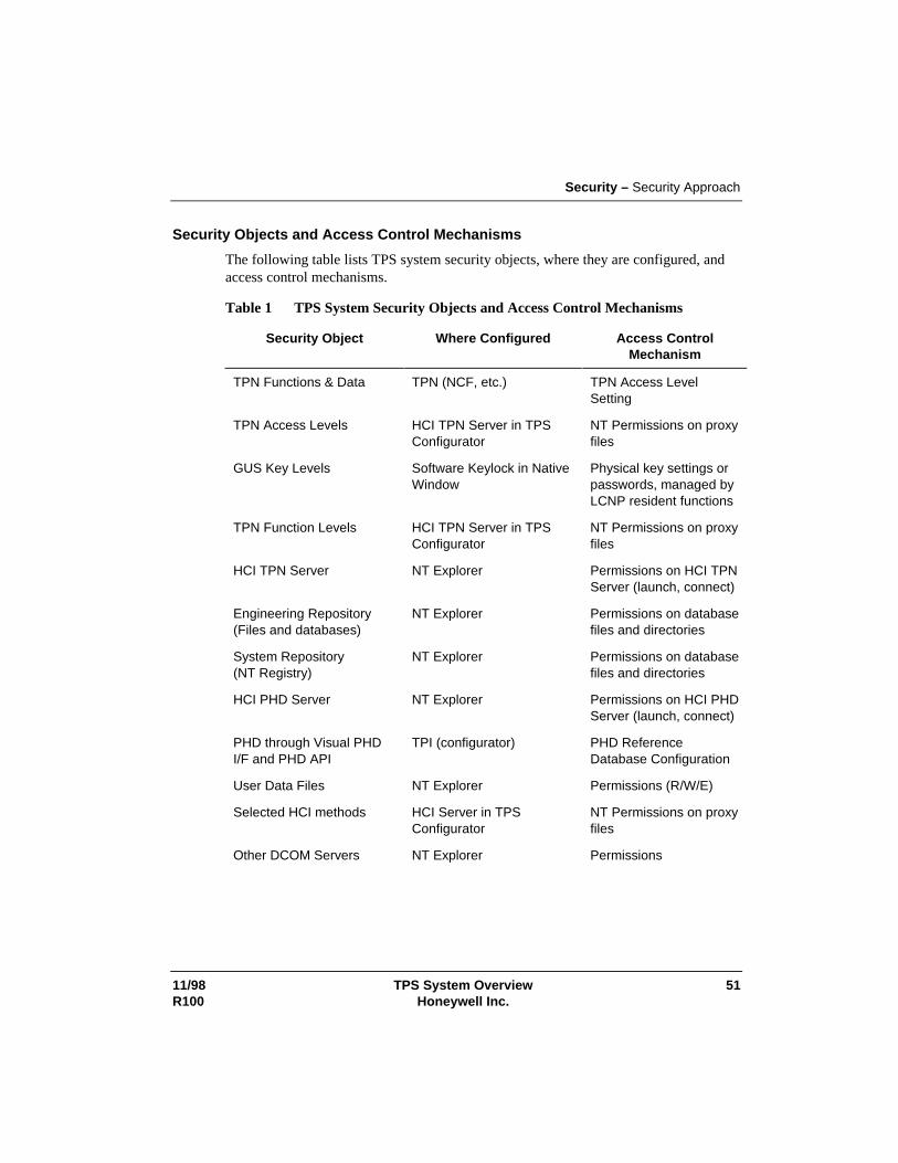
Security – Security Approach
11/98 TPS System Overview 51R100 Honeywell Inc.
Security Objects and Access Control Mechanisms
The following table lists TPS system security objects, where they are configured, andaccess control mechanisms.
Table 1 TPS System Security Objects and Access Control Mechanisms
Security Object Where Configured Access ControlMechanism
TPN Functions & Data TPN (NCF, etc.) TPN Access LevelSetting
TPN Access Levels HCI TPN Server in TPSConfigurator
NT Permissions on proxyfiles
GUS Key Levels Software Keylock in NativeWindow
Physical key settings orpasswords, managed byLCNP resident functions
TPN Function Levels HCI TPN Server in TPSConfigurator
NT Permissions on proxyfiles
HCI TPN Server NT Explorer Permissions on HCI TPNServer (launch, connect)
Engineering Repository(Files and databases)
NT Explorer Permissions on databasefiles and directories
System Repository(NT Registry)
NT Explorer Permissions on databasefiles and directories
HCI PHD Server NT Explorer Permissions on HCI PHDServer (launch, connect)
PHD through Visual PHDI/F and PHD API
TPI (configurator) PHD ReferenceDatabase Configuration
User Data Files NT Explorer Permissions (R/W/E)
Selected HCI methods HCI Server in TPSConfigurator
NT Permissions on proxyfiles
Other DCOM Servers NT Explorer Permissions
Security – Security Approach
52 TPS System Overview 11/98Honeywell Inc. R100
TPS Builder
The TPS Builder uses the NT user Log-in and built in security at the file level toprovide access to logging into NT, running the application itself, and accessing theconfiguration data in the database files.
11/98 TPS System Overview 53R100 Honeywell Inc.
Related Products and Applications
Network and Integration Services Network and Integration Services offer design, implementation, maintenance, andoptimization of networks to support the mission-critical applications within the plant.This includes "industrial-strength networks," which possess the reliability, robustness,performance, and security traditionally associated with the process control network.The following services are available.
• Consulting and Design Services
• Baseline and Assessment Services
• Integration Engineering Services
• Network Administration and Support
• Performance Management Services
• Network Monitoring Services
User Alert User Alert is an Abnormal Situation Management (ASM) application designed toenable the operator to proactively define automated alerts that assist with the overallmonitoring and control of the process unit and its associated on-going tasks. The UserAlert concept has been validated through involvement and feedback from the AbnormalSituation Management Industry consortium.
The User Alert application provides the mechanism for industrial board operators to bealerted when user-defined conditions have occurred, thereby improving effectivenessby minimizing the constant recall requirements of the operator and by reducing theloading of the alarm system. By leveraging the TPS system functionality, the UserAlert application automatically monitors plant conditions which, if not attended, couldresult in reduced operating performance, abnormal incidents, or plant losses. Thistechnology breakthrough offers more unit integrity and confidence to operators andplant management than ever before and is unmatched in the operating environment.
Equipment Health Management (EHM) Equipment Health Management (EHM) solutions focus on plant maintenance andreliability. These solutions balance reliability, predictive, and preventive maintenancestrategies to deliver optimum plant availability.
Related Products and Applications – Advanced Control Applications
54 TPS System Overview 11/98Honeywell Inc. R100
EHM gathers data from specific plant assets for analysis and action. As an opensolution, it can be applied to any asset. Typical plant assets include pumps, motors,heat exchangers, analyzers, instrumentation, compressors, control valves, pressurerelief valves, and more. Reliability and maintenance engineers are provided with aconsistent desktop environment that gathers data from a variety of sources, such asengineering documents, plant history, maintenance records, field sensors, and controlsystems. Through the EHM Alert Manager, data is analyzed and organized intosymptoms and faults. This is accomplished by incorporating new Honeywell solutions,such as heat exchanger and control valve analysis, along side with third party providersfor vibration monitoring, motor analysis, and other niche solutions. The ReliabilityEngineer can then automate follow-up through the direct integration with computer-based maintenance management and documentation systems.
Advanced Control Applications Advanced control applications are hosted on Windows NT-based TPS nodes (such asthe APP or TPS Client node) and are an integral part of the TPS system architecture.These applications provide the essential technologies for enabling companies in theprocess industries to compete effectively and attain profitability goals. Theseapplications include
• Profit Suite
• Oil Movement and Storage
• TotalPlant Batch
Profit Suite
Profit Suite provides a layered approach to advanced control and optimization.Following a bottoms-up methodology, each application layer adds an increased level ofoptimization capability. Because applications are complementary and designed to worktogether effectively, they represent an easily expandable optimization system.
Profit Suite applications provide the following increasing levels of capability.
• Profit Controller, employing Honeywell’s Robust Multivariable ControlTechnology (RMPCT), the industry’s leading algorithm for advanced control andlocal optimization
• Profit Optimizer, incorporating breakthrough cooperative optimization technologyfor steady-state and dynamic optimization across multiple units of a plant
• ProfitMax, a first-principles process modeling and non-linear optimization systemfor highly non-linear processes or those demanding extensive modeling efforts.ProfitMax incorporates Dot Products’ world-leading NOVA™ open-equationoptimization and modeling system
Related Products and Applications – Advanced Control Applications
11/98 TPS System Overview 55R100 Honeywell Inc.
Oil Movements and Storage
Oil Movements and Storage (OM&S) application software package provides refineryoff-sites tools for carrying out oil movement operations more effectively. Theseinclude the following.
• The OM&S Storage Data Management (SDM) that collects and maintainsinformation pertaining to the status and contents of each tank at a refinery
• The OM&S Blend Ratio Control (BRC) that controls the in-line blending process toensure that blended products meet blend recipe specifications
• The OM&S Blend Property Control (BPC) that allows operations to efficientlyblend fuels to the required specifications, while optimizing the blend
• The OM&S Task Monitor Module (TMM) that helps operators manage andprioritize the many simultaneous activities involved in material movement
• The OM&S Task Control Module (TCM) provides facilities for automating andcontrolling movement operations
• The Path Finder Module (PFM) is an optional enhancement to TMM and TCM,which improves on the oil movement facilities provided by these modules
• The OM&S Off-Sites Database Module (ODM) provides facilities for thecollection, archiving, and reporting of inventory, blend, task and laboratory data in arelational database environment
TotalPlant Batch
TotalPlant Batch is Honeywell’s batch automation solution. Its provides thefunctionality to manage and coordinate operations in batch processes. TotalPlantBatch is scaleable and integrated with TPS system. It provides standard displays formonitoring and controlling of batch operations. The Archiver option permits theexporting of batch journals to ODBC complaint relational databases and otherapplications for batch reporting and analysis.
Related Products and Applications – Advanced Control Applications
56 TPS System Overview 11/98Honeywell Inc. R100
TotalPlant Batch is provided with a set of graphical configuration tools to simplifyproject implementation. Equipment Editor is used to define the batch processequipment and Recipe Editor is used to create and manage the library of master recipes.
11/98 TPS System Overview 57R100 Honeywell Inc.
Glossary
Acronyms and AbbreviationsAcronyms and abbreviations used in this document include the following.
AM — Application Module; A proprietary node on the TPS Network that provides a platformfor advanced control applications
AMW — AM Personality Image loaded into the LCNP portion of an APP
APM —Advanced Process Manager
APP — Application Processing Platform
ASM — Abnormal Situation Management
BDC — Backup Domain Controller
CL — Control Language
CM50 — Computer Module 50
DEB — Data Entity Builder
DCOM— Distributed Component Object Model
DQ — Dynamic Query
EHM —Equipment Health Management
FSC — Fail Safe Controller
GUS — Global User Station
HCI — Honeywell Communications Interface
HCI/OPC — The complete set of interfaces and functions available to client applications usedto access HCI named data.
HM — History Module; a proprietary node on the TPS Network that serves as the historian andfile server.
HOPC —This term refers to Honeywell’s proprietary interface to the TPS Network data andalarms.
HPM— High Performance Process Manager
IQ — Interactive Query
Glossary
58 TPS System Overview 11/98Honeywell Inc. R100
K4LCN — An LCN Card that runs a TPN personality (such as AM, HM)
LCN — Local Control Network (now referred to as the TPN)
LCNP or LCNP4 —Local Control Network Processor boards
LM —Logic Manager
MQ — Microsoft Query
NCF — Network Configuration File
OPC — OLE (Object Linking and Embedding) for Process Control
PCN —Plant Control Network
PDC —Primary Domain Controller
PHD — Process History Database
PM — Process Manager
PV — Process Variable
RDI — Realtime Data Interface
SP — Set Point
TDC 3000 — The primary control system offered by Honeywell prior to release 410. Thisincludes the TPN, UCN, and connected field devices.
TPI — TotalPlant Information
TPN — TPS Network
TPS — TotalPlant Solution
TPSDDE — TotalPlant Solution Dynamic Data Exchange – a server of TPN data used forDDE aware applications (e.g., Excel)
UCN — Universal Control Network
UNPW —Universal Personality for Workstation
US —Universal Station
Glossary
11/98 TPS System Overview 59R100 Honeywell Inc.
TerminologySpecialized terminology used in this document includes:
Application Processing Platform — The Application Processing Platform (APP) is theopen application host for the Honeywell TPS system. It is a secure application hostthat makes it possible to integrate advanced control or information managementapplications.
NT Domain — A group of computers and devices on a network that are administered as a unitwith common rules and procedures. The NT domain provides an administrator asingle point from which to administer user accounts, hard drives (shares), and networkprinters.
Global User Station — Global User Station is an intuitive and productive human interface tothe Honeywell TPS system. This station makes plant-wide information easilyaccessible for needed business and control information.
HCI Managed Components — named DCOM servers that support the value addedHCI/OPC interfaces and can be managed through the TPS Status Display. Each HCIManaged Component has a unique name within a TPS Domain.
HCI Named Data — Data that is within or owned by an HCI Managed Component and isaccessible as a named TPS object. The object name is an extension of the TPN datapoint concept and must be unique within that HCI Managed Component.
Plant Control Network – The portion of the Plant Intranet, which connects control criticalTPS nodes. It is isolated from the Plant Intranet through router/bridges for securityand robustness purposes. This network is also known as the “industrial-strength”network.
Plant Intranet — The Plant Intranet is the open network that exists throughout the plant; isused by plant personnel for viewing process data, but is not guaranteed to have near100% availability.
TPS Domain — The namespace of a TPS system and all physical TPS nodes defined withinthat namespace. It is defined within an NT domain and uses the NT’s domain’s namesfor physical nodes, user Ids, and user groups for security checking.
TPS Network— Refers to the control platform underlying the TPS system (TPN and UCN).
TPS Node — This is a general generic term that collectively refers to a node on which TPSruns and is part of a TPS domain. It can refer to a GUS node, APP, and/or other typesof TPS nodes.
60 TPS System Overview 11/98Honeywell Inc. R100
TotalPlant Solution System (TPS system) — Beginning with R510 and with the introductionof GUS, TDC 3000X evolved to become the TotalPlant Solution system (TPS systemfor short). This name applies to any system running R510 or later software, regardlessof the presence of a TPS component.
Uniformance — TPS Uniformance (from Unified for Performance) is a unified informationand applications software system residing within Honeywell’s TotalPlant Solution(TPS) system to enable improved plant management and performance. The systemprovides a comprehensive solution to meet complex and demanding plant managementneeds in the process industries.
FAX Transmittal FAX No.: (602) 313-4842
To: Bill Cline Total FAX pages:(including this page)
Reader CommentsTitle of Document: TPS System Overview
Document Number: TP01100 Issue Date: 11/98
Comments:
Recommendations:
FROM: Name: Date:
Title:
Company:
Address:
City: State: ZIP:
Telephone: FAX:
FOR ADDITIONAL ASSISTANCE
Write Call
Honeywell Inc.Industrial Automation and Control
Automation College2820 West Kelton Lane
Phoenix, AZ 85053-3028
Technical Assistance Center (TAC)1-800-822-7673 (48 contiguous states except Arizona)
602-313-5558 (Arizona)


Industrial Automation and Control
Automation College
2820 W. Kelton Lane
Phoenix, AZ 85053-3028