Embed Size (px)
Citation preview
TOYOTA tC 2011- HANDS FREE BLU LOGIC Preparation
Page 1 of 12Issue A: 08/25/10
Item 2 Item 3 Item 5 Item 6 Item 7 Item 8Item 4
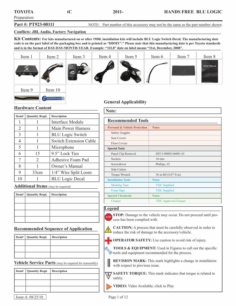
Part #: PT923-00111 NOTE: Part number of this accessory may not be the same as the part number shown.
Conflicts: JBL Audio, Factory Navigation
Kit Contents: For kits manufactured on or after 19D0, installation kits will include BLU Logic Switch Decal. The manufacturing date code is on the part label of the packaging box and is printed as “DDMY”.” Please note that this manufacturing date is per Toyota standards and is in the format of DAY-DAY-MONTH-YEAR. Example: “31L8” date on label means “31st, December, 2008”.
Hardware Content
Item# Quantity Reqd. Description
1 1 Interface Module2 1 Main Power Harness3 1 BLU Logic Switch4 1 Switch Extension Cable5 1 Microphone6 15 9.5” Lock Ties7 2 Adhesive Foam Pad8 1 Owner’s Manual9 33cm 1/4” Wire Split Loom
10 1 BLU Logic DecalAdditional Items (may be required)
Item# Quantity Reqd. Description
Recommended Sequence of Application
Item# Quantity Reqd. Description
Vehicle Service Parts (may be required for reassembly)
Item# Quantity Reqd. Description
LegendSTOP: Damage to the vehicle may occur. Do not proceed until pro-cess has been complied with.
CAUTION: A process that must be carefully observed in order to reduce the risk of damage to the accessory/vehicle.
OPERATOR SAFETY: Use caution to avoid risk of injury.
TOOLS & EQUIPMENT: Used in Figures to call out the specific tools and equipment recommended for the process.
REVISION MARK: This mark highlights a change in installation with respect to previous issue.
SAFETY TORQUE: This mark indicates that torque is related to safety.
VIDEO: Video Available; click to Play
Item 9
Recommended ToolsPersonal & Vehicle Protection Notes
Safety Goggles
Seat Covers
Floor Covers
Special Tools
Panel Clip Removal SST # 00002-06001-01
Sockets 10 mm
Screwdriver Phillips, #2
Side Cutters
Torque Wrench 36 in-lbf (4.07 N.m)
Installation Tools Notes
Masking Tape VDC Supplied
Foam Tape VDC Supplied
Special Chemicals Notes
Cleaner VDC Approved Cleaner
General Applicability
Note:
Item 10
Item 1

TOYOTA tC 2011- HANDS FREE BLU LOGIC Preparation
Page 2 of 12Issue A: 08/25/10
I. Preparation ............................................................................................................................................... 1-21. Table Of Contents.................................................................................................................................. 22. Content Location ....................................................................................................................................3
II. Procedure................................................................................................................................................ 4-111. Vehicle Preparation................................................................................................................................ 42. Vehicle Disassembly.............................................................................................................................. 43. Interface Module Installation .................................................................................................................54. BLU Logic Switch Installation ..............................................................................................................75. Microphone Installation .........................................................................................................................96. Finalize Installation ..............................................................................................................................117. Apply BLU Logic Decal to Switch ......................................................................................................11
III. Checklist ....................................................................................................................................................121. Accessory Function Checks .................................................................................................................122. Vehicle Function Checks ......................................................................................................................12
Accessory Installation Practice (read before installation)Care must be taken when installing this accessory to ensure damage does not occur to the vehicle. The installation of this accessory should follow approved guidelines to ensure a quality installation.
These guidelines can be found in the “Accessory Installation Practices” document.
This document covers such items as:• Vehicle Protection (use of covers and blankets, cleaning chemicals, etc.)• Safety (eye protection, checking torque procedure, etc.)• Vehicle Disassembly/Reassembly (panel removal, part storage, etc.)• Electrical Component Disassembly/Reassembly (battery disconnection, connector removal, etc.)
Please see your Toyota/Scion/Lexus dealer for a copy of this document.
TOYOTA tC 2011- HANDS FREE BLU LOGIC Preparation
Page 3 of 12Issue A: 08/25/10
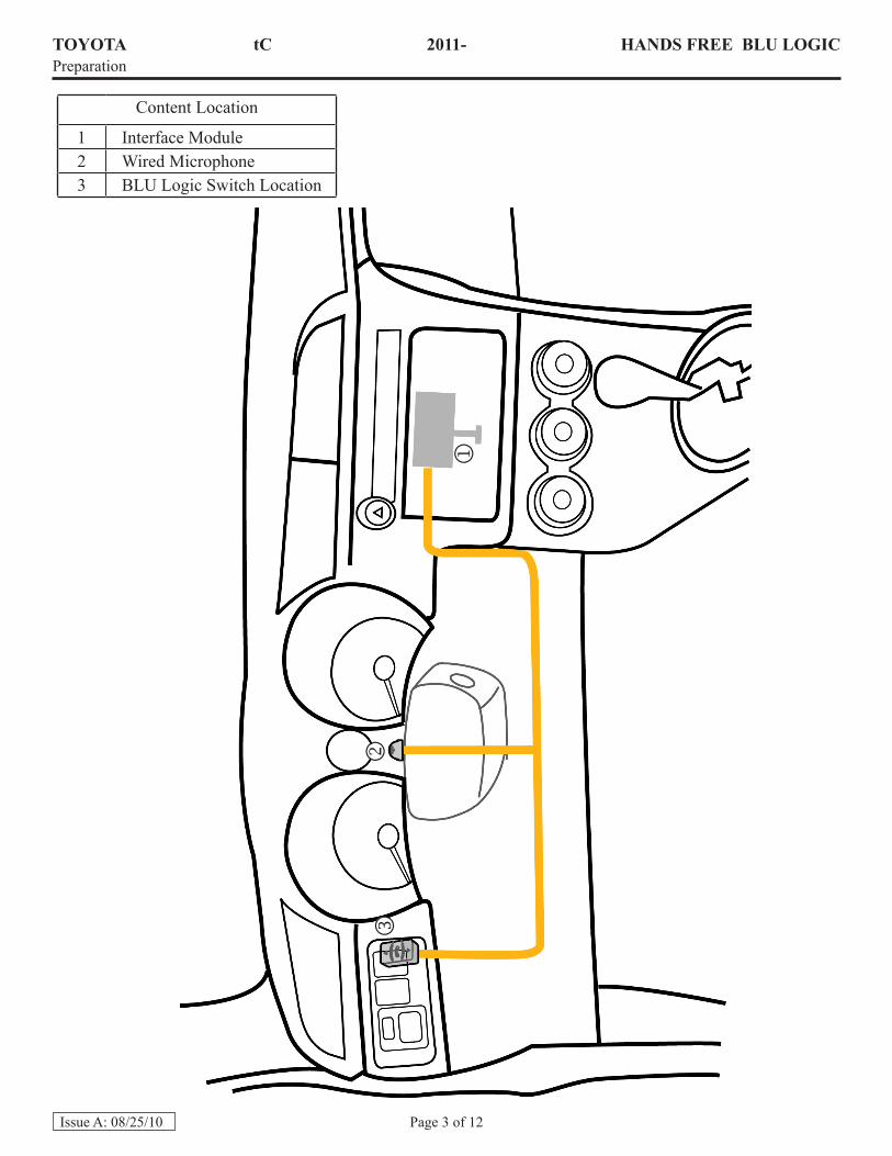
Content Location
1 Interface Module2 Wired Microphone3 BLU Logic Switch Location

TOYOTA tC 2011 - HANDS FREE BLU LOGICProcedure
Page 4 of 12Issue A: 08/25/10
1. Vehicle Preparation (Fig. 1-1)
a. Apply parking brake.b. Protect fender before starting.c. Remove the negative (–) battery cable.
CAUTION: Do not touch the positive termi-nal with any tool during removal. d. Using the protective blanket, cover front
seat, top of the shift lever and center console.
e. Place removed vehicle components on a protective blanket. Fig. 1-1
3. Using a 10mm socket/ratchet, remove four (4) bolts securing the radio (Fig. 1-3).
4. Support the radio assembly on a sup-port box (or with other appropriate means) to prevent any damage to the connections as well as preventing scratches to any car panel(s).
NOTE: Be careful not to put too much ten-sion on the radio connections when pulling out the radio.
5. Disconnect all connectors and set radio assembly aside.
2. Vehicle Disassembly
a. Remove radio assembly.
1. Using hands or appropriate panel removal tool, disengage the bottom of the radio bezel (Fig. 1-2).
NOTE: Apply protective tape to any pry area.
2. Disconnect any connectors and re-move.
Fig. 1-2
Socket (10 mm), Ratchet
Fig. 1-3
Panel Removal Tool
Socket (10 mm), Ratchet
TOYOTA tC 2011 - HANDS FREE BLU LOGICProcedure
Page 5 of 12Issue A: 08/25/10
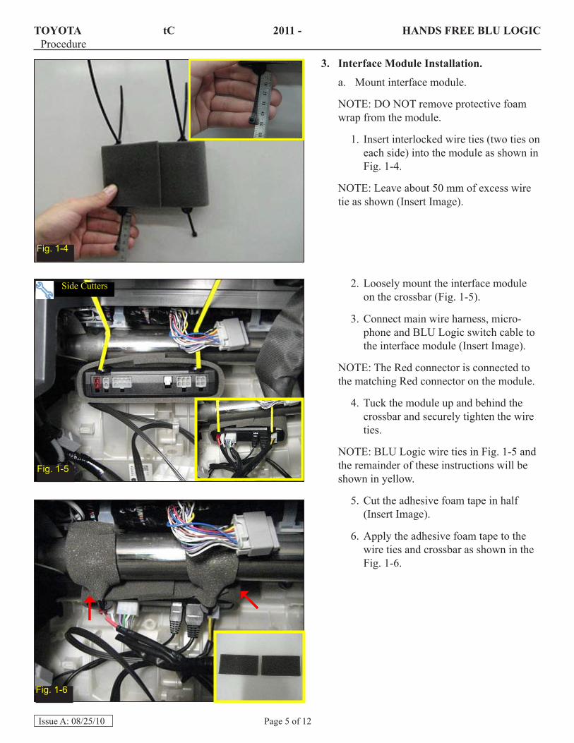
3. Interface Module Installation.
a. Mount interface module.
NOTE: DO NOT remove protective foam wrap from the module.
1. Insert interlocked wire ties (two ties on each side) into the module as shown in Fig. 1-4.
NOTE: Leave about 50 mm of excess wire tie as shown (Insert Image).
Fig. 1-4
Fig. 1-5
Fig. 1-6
Side Cutters
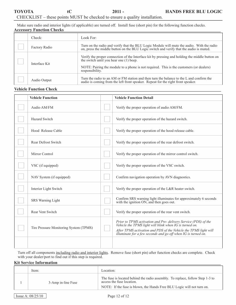
2. Loosely mount the interface module on the crossbar (Fig. 1-5).
3. Connect main wire harness, micro-phone and BLU Logic switch cable to the interface module (Insert Image).
NOTE: The Red connector is connected to the matching Red connector on the module.
4. Tuck the module up and behind the crossbar and securely tighten the wire ties.
NOTE: BLU Logic wire ties in Fig. 1-5 and the remainder of these instructions will be shown in yellow.
5. Cut the adhesive foam tape in half (Insert Image).
6. Apply the adhesive foam tape to the wire ties and crossbar as shown in the Fig. 1-6.

TOYOTA tC 2011 - HANDS FREE BLU LOGICProcedure
Page 6 of 12Issue A: 08/25/10
7. Secure the main harness to the tab on the blower box (Fig. 1-7)
8. Connect main wire harness to match-ing factory radio harness and secure with wire tie (Fig. 1-8).
NOTE: AVC-LAN (12 pin) connector may not be present on the vehicle’s harness. Wire tie this connector to the harness unconnect-ed, but ALWAYS connect the AVC-LAN (12 pin) connector into the radio.
If AVC-LAN (12 pin) connector is present on vehicle harness, connect to jumper pro-vided with BLU Logic unit.
9. Bundle up the excess main harness and secure it to the vehicle wire harness (Fig. 1-9).
Fig. 1-7
Fig. 1-8
Fig. 1-9
Side Cutters

TOYOTA tC 2011 - HANDS FREE BLU LOGICProcedure
Page 7 of 12Issue A: 08/25/10
Socket (10 mm), Ratchet
4. BLU Logic Switch Installation.
a. Remove lower steering column cover.
1. Turn the steering wheel to access the steering column cover release holes (Fig. 1-10).
NOTE: There are two release holes, one on the right and one of the left of the steering column cover.
2. Insert appropriate steering column cover release tool and gently pull down on the cover.
2. Using a 10mm socket/ratchet, remove the two (2) upper bolts securing the knee air bag assembly (Fig. 1-12).
3. Carefully remove the airbag assembly and rest it on an appropriate protective cover/support.
NOTE: Do not put too much tension on the airbag cable(s).
b. Remove knee air bag assembly.
1. Using a 10mm socket/ratchet, remove the two (2) lower bolts securing the knee air bag assembly (Fig. 1-11).
10mm Socket/Ratchet
Cover Release Tool
Fig. 1-10
Fig. 1-11
Fig. 1-12

TOYOTA tC 2011 - HANDS FREE BLU LOGICProcedure
Page 8 of 12Issue A: 08/25/10
c. Remove left knee trim panel.
1. Using hands or appropriate trim removal tool, disengage the left knee trim panel and remove (Fig. 1-13).
NOTE: Apply protective tape to any pry area.
d. Route BLU Logic cable (highlighted in blue).
1. Route switch extension cable and microphone towards the opening of the knee panels and behind LH round metal reinforcement (Fig. 1-14).
Panel Removal Tool
Panel Removal Tool
Fig. 1-13
Fig. 1-14
Fig. 1-15
2. Loosely secure the switch and micro-phone cable to the existing wire loom with two (2) wire ties pointed out by the red arrow (Fig. 1-15).
3. Loosely secure the remainder of the switch extension cable with three (3) wire ties as shown (Fig. 1-15).

TOYOTA tC 2011 - HANDS FREE BLU LOGICProcedure
Page 9 of 12Issue A: 08/25/10
4. Position the switch connector about 4-5 inches from the white connector plug (Red Arrow, Fig. 1-16).
5. Tighten the three (3) left wire ties.
NOTE: The wire ties pointed out by the red arrows in Figure 1-15 will be tighten once the microphone wire is routed.
Fig. 1-16 e. Mount BLU Logic Switch.
1. Remove the far right blank knock-out and mount the BLU Logic switch with the solid arrow pointing up (Fig. 1-17).
2. Connect the switch to the switch ex-tension cable.
5. Microphone Installation
a. Mount the microphone.
1. Clean the mounting location (top of steering column) with VDC approved cleaner.
2. Position the steering column all the way up and in (Most critical position to verify clearance between micro-phone and other components in the surrounding).
3. Mount the microphone visually center and towards the rear of the steering column to minimize the amount of exposed wire visible to the customer. Approximately 40 mm to the end of the steering column shroud (Fig. 1-18).
NOTE: Make sure the microphone wire is on the left side of the steering assembly.
4. Operate the telescope and tilt function to make sure the microphone does not interfere with the movement of the steering wheel.
Fig. 1-17
Fig. 1-18
Side Cutters

TOYOTA tC 2011 - HANDS FREE BLU LOGICProcedure
Page 10 of 12Issue A: 08/25/10
b. Route Microphone Cable
1. Route microphone cable (highlighted in blue).
2. Remove most of the slack from the microphone.
3. Using 1.5-2 inches of adhesive foam pad, secure the microphone cable to the inside of the top steering column (Fig. 1-19).
Fig. 1-19
Fig. 1-20
Side Cutters
Side Cutters
Fig. 1-21
4. Secure the microphone wire to the vehicle harness under the steering as-sembly with two wire ties (Fig. 1-20).
5. Remove all the slack from the micro-phone wire and bundle it to the support frame as shown (Fig. 1-21).
6. Tighten the two wire ties from Step 4.d.2 and cut off any excess wire ties.

TOYOTA tC 2011 - HANDS FREE BLU LOGICProcedure
Page 11 of 12Issue A: 08/25/10
Fig. 1-22
6. Finalize the Installation.
a. Reinstall the lower portion of the steer-ing column.
b. Reinstall the knee air bag assembly and the two knee trim panels (Fig. 1-22).
c. Reinstall the kick panel and the door sill.d. Reinstall the radio assembly and radio
bezel.
NOTE: If any other accessories are installed that connect to the head unit, BLU Logic should be the unit that plugs into the radio first.e. Position negative battery terminal at the
original factory position (tighten the nut to 36 in-lb (4.07 N.m).
CAUTION: Do not touch the positive termi-nal with any tool during installation.
7. Apply BLU Logic decal to BLU Logic switch. (Only kits manufactured on or after the date code on the front page will include the BLU Logic decal).
a. Remove the protective backing on the round portion of the BLU Logic sticker (Fig. 1-23).
b. Apply it to the center of the switch so that the sticker hangs towards the right.
NOTE: Photo shown may not match the switch installation location for this vehicle and is for illustrative purposes.
Fig. 1-23
TOYOTA tC 2011 - HANDS FREE BLU LOGICCHECKLIST – these points MUST be checked to ensure a quality installation.
Page 12 of 12Issue A: 08/25/10
Accessory Function Checks
Check: Look For:
Factory Radio Turn on the radio and verify that the BLU Logic Module will mute the audio. With the radio on, press the middle button on the BLU Logic switch and verify that the audio is muted.
Interface Kit
Verify the proper connection of the Interface kit by pressing and holding the middle button on the switch until you hear one (1) beep.
NOTE: Pairing the module to a phone is not required. This is the customers (or dealers) responsibility.
Audio Output Turn the radio to an AM or FM station and then turn the balance to the L and confirm the audio is coming from the left front speaker. Repeat for the right front speaker.
Vehicle Function Check
Vehicle Function Vehicle Function Detail
Audio AM/FM Verify the proper operation of audio AM/FM.
Hazard Switch Verify the proper operation of the hazard switch.
Hood Release Cable Verify the proper operation of the hood release cable.
Rear Defrost Switch Verify the proper operation of the rear defrost switch.
Mirror Control Verify the proper operation of the mirror control switch.
VSC (if equipped) Verify the proper operation of the VSC switch.
NAV System (if equipped) Confirm navigation operation by AVN diagnostics.
Interior Light Switch Verify the proper operation of the L&R heater switch.
SRS Warning Light Confirm SRS warning light illuminates for approximately 6 seconds with the ignition ON, and then goes out.
Rear Vent Switch Verify the proper operation of the rear vent switch.
Tire Pressure Monitoring System (TPMS)
Prior to TPMS activation and Pre- delivery Service (PDS) of the Vehicle the TPMS light will blink when IG is turned on.After TPMS activation and PDS of the Vehicle the TPMS light will illuminate for a few seconds and go off when IG is turned on.
Kit Service Information
Item: Location:
1 3-Amp in-line FuseThe fuse is located behind the radio assembly. To replace, follow Step 1-3 to access the fuse location.NOTE: If the fuse is blown, the Hands Free BLU Logic will not turn on.
Make sure radio and interior lights (if applicable) are turned off. Install fuse (short pin) for the following function checks.
Turn off all components including radio and interior lights. Remove fuse (short pin) after function checks are complete. Check with your dealer/port to find out if this step is required.


![Index []INDEX Item Section Page Bridge Storing Material and Equipment On/Against Structures Restriction..... TC-6.14 115 Bridge Underclearance ..... TC-6.12 113](https://img.pdfslide.us/doc/110x75/5e32d981936425078231de8a/index-index-item-section-page-bridge-storing-material-and-equipment-onagainst.jpg)