Embed Size (px)
Citation preview
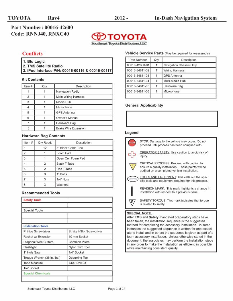
Part Number Qty Description
00016-42600-01 1 Navigation Chassis Only
00016-34811-02 1 Wiring Harness
00016-34811-03 1 GPS Antenna
00016-34811-04 1 Multi-Media Hub
00016-34811-05 1 Hardware Bag
00016-34811-06 1 Microphone
Vehicle Service Parts (May be required for reassembly)
Legend
STOP: Damage to the vehicle may occur. Do not proceed until process has been complied with.
OPERATOR SAFETY: Use caution to avoid risk of injury.
CRITICAL PROCESS: Proceed with caution to ensure a quality installation. These points will be audited on a completed vehicle installation.
TOOLS AND EQUIPMENT: This calls out the spe-cifi c tools and equipment required for this process.
REVISION MARK: This mark highlights a change in installation with respect to a previous issue.
SAFETY TORQUE: This mark indicates that torque is related to safety.
STOP
S
SPECIAL NOTE:After TMS and Safety mandated preparatory steps have been taken, the installation sequence is the suggested method for completing the accessory installation. In some instances the suggested sequence is written for one associ-ate to install and in others the sequence is given as part of a team accessory installation. Unless otherwise stated in the document, the associates may perform the installation steps in any order to make the installation as effi cient as possible while maintaining consistent quality.
Safety Tools
Special Tools
Installation ToolsPhillips Screwdriver Straight-Slot Screwdriver
Rachet w/ Extension 10 mm Socket
Diagonal Wire Cutters Common Pliers
Flashlight Nylon Trim Tool
1” Hole Saw 1/4” Socket
Troque Wrench (36 in. lbs.) Deburring Tool
Tape Measure 7/64” Drill Bit
1/4” Socket
Special Chemicals
Recommended Tools
Item # Qty Reqd. Description
1 12 8” Black Cable Ties
2 1 Foam Pad
3 1 Open Cell Foam Pad
4 2 Black T-Taps
5 2 Red T-Taps
6 3 1” Bolts
7 3 1/4” Nuts
8 3 Washers
Hardware Bag Contents
Item # Qty Description
1 1 Navigation Radio
2 1 Main Wiring Harness
3 1 Media Hub
4 1 Microphone
5 1 GPS Antenna
6 1 Owner’s Manual
7 1 Hardware Bag
8 1 Brake Wire Extension
Kit Contents
1. Blu Logic2. TMS Satellite Radio3. iPod Interface P/N: 00016-00116 & 00016-00117
!
TOYOTA Rav4 2012 - In-Dash Navigation System
General Applicability
Conflicts
Part Number: 00016-42600Code: RNNJ40, RNXC40
Southeast Toyota Distributors, LLC Page 1 of 14
Toyota Rav 4
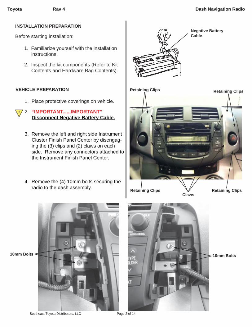
INSTALLATION PREPARATION
Before starting installation:
1. Familiarize yourself with the installation instructions.
2. Inspect the kit components (Refer to Kit Contents and Hardware Bag Contents).
Negative Battery Cable
Claws
Retaining Clips
!
VEHICLE PREPARATION
1. Place protective coverings on vehicle.
2. “IMPORTANT......IMPORTANT” Disconnect Negative Battery Cable.
3. Remove the left and right side Instrument Cluster Finish Panel Center by disengag-ing the (3) clips and (2) claws on each side. Remove any connectors attached to the Instrument Finish Panel Center.
4. Remove the (4) 10mm bolts securing the
radio to the dash assembly.
Retaining Clips
Retaining Clips Retaining Clips
10mm Bolts10mm Bolts
Dash Navigation Radio
Southeast Toyota Distributors, LLC Page 2 of 14

Toyota Rav 4
VEHICLE PREPARATION; continued5. Disconnect any connectors attached to
the rear of the radio and remove the radio from the vehicle.
6. Remove the air conditioning control assembly by removing the (2) phillips screws and disengaging the (3) retaining clips.
7. Disconnect any connectors attached to the rear of the air conditioning control as-sembly.
8. Remove the instrument Panel Register by disengaging the (5) retainer clips.
Dash Navigation Radio
Southeast Toyota Distributors, LLC Page 3 of 14
NOTE: Remove factory USB and replace with blank knockout.
Toyota Rav 4
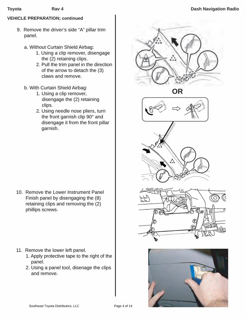
VEHICLE PREPARATION; continued 9. Remove the driver’s side “A” pillar trim
panel.
a. Without Curtain Shield Airbag: 1. Using a clip remover, disengage
the (2) retaining clips. 2. Pull the trim panel in the direction
of the arrow to detach the (3) claws and remove.
b. With Curtain Shield Airbag: 1. Using a clip remover,
disengage the (2) retaining clips. 2. Using needle nose pliers, turn the front garnish clip 90° and
disengage it from the front pillar garnish.
10. Remove the Lower Instrument Panel Finish panel by disengaging the (8) retaining clips and removing the (2) phillips screws.
11. Remove the lower left panel. 1. Apply protective tape to the right of the
panel. 2. Using a panel tool, disenage the clips
and remove.
OR
Dash Navigation Radio
Southeast Toyota Distributors, LLC Page 4 of 14
Toyota Rav 4
INSTALLATION PROCEDURES
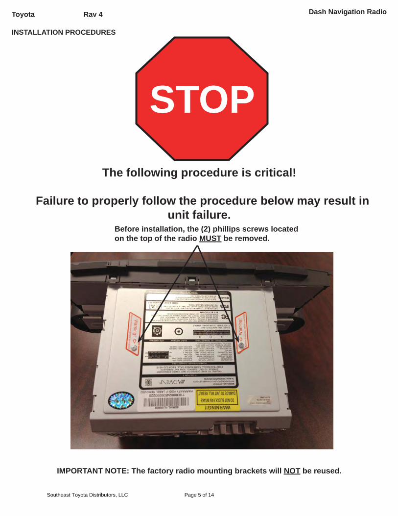
STOPThe following procedure is critical!
Failure to properly follow the procedure below may result in unit failure.
Before installation, the (2) phillips screws located on the top of the radio MUST be removed.
IMPORTANT NOTE: The factory radio mounting brackets will NOT be reused.
Dash Navigation Radio
Southeast Toyota Distributors, LLC Page 5 of 14
Toyota Rav 4
INSTALLATION PROCEDURES; continued
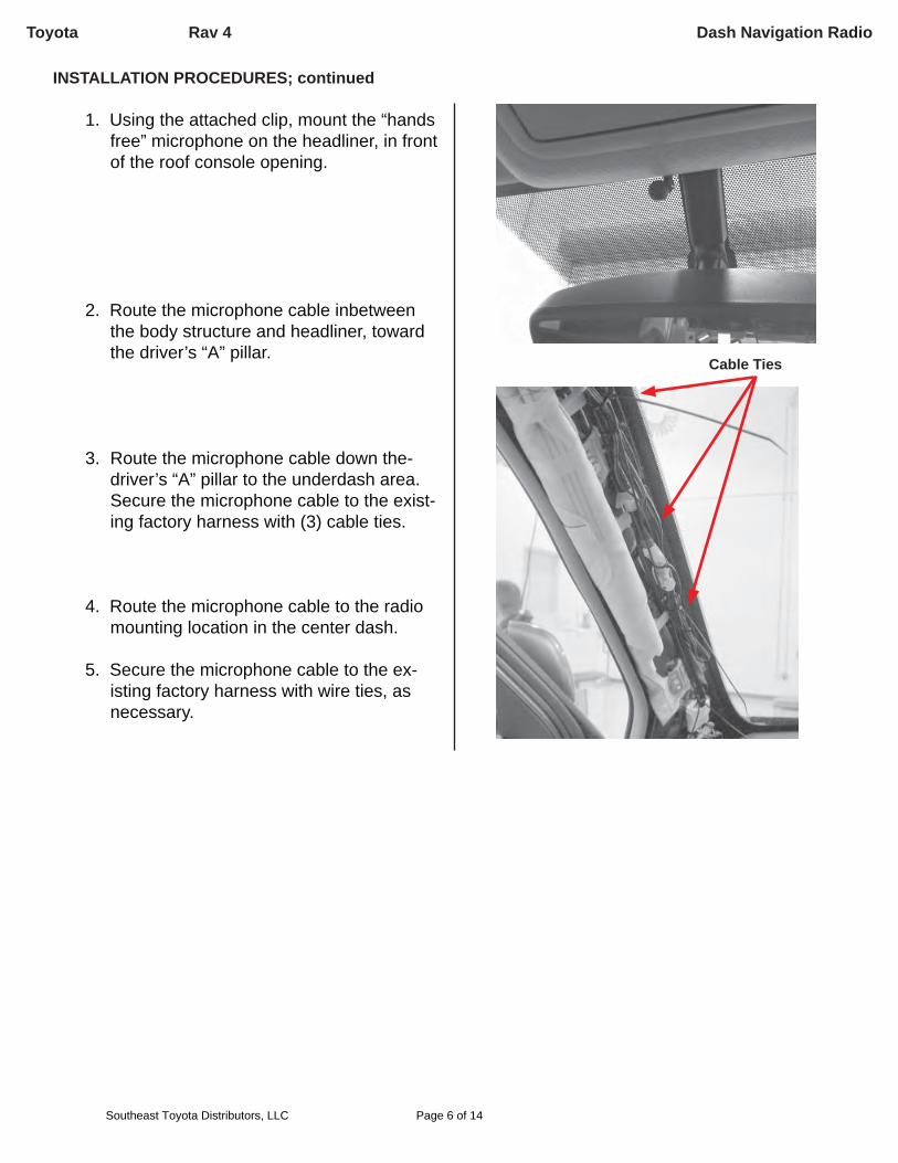
1. Using the attached clip, mount the “hands free” microphone on the headliner, in front of the roof console opening.
2. Route the microphone cable inbetween the body structure and headliner, toward the driver’s “A” pillar.
3. Route the microphone cable down the-driver’s “A” pillar to the underdash area. Secure the microphone cable to the exist-ing factory harness with (3) cable ties.
4. Route the microphone cable to the radio mounting location in the center dash.
5. Secure the microphone cable to the ex-isting factory harness with wire ties, as necessary.
Cable Ties
Dash Navigation Radio
Southeast Toyota Distributors, LLC Page 6 of 14

Toyota Rav 4
Cable TiesCable Ties
INSTALLATION PROCEDURES; continued
6. Route the radio harness extension wire from the driver’s JB to the Blue/Black connector located on the back of the radio harness.parking brake wire to the driver’s JB.
T-TAP INSTALLATIONWhen installing female T-Tap connectors, be sure the wire is located inside the wire channel of the female T-Tap connector before closing the connector over the wire with pliers.
IMPORTANT! After installation, inspect and ensure that the module harnesses are clear of HOT, SHARP or MOVING objects.STOP
Step A Step B Step C
7. Locate the Black (Pin 4) wire of the ID con-nector at the driver’s JB.
8. Install (1) red T-Tap on the Black wire.
9. Connect the male terminal end of the radio harness Blue/Black parking brake wire to the red T-Tap installed in step 17.
Radio Harness Vehicle
Blue/Black Black
Parking BrakeBlack WirePin 4
Dash Navigation Radio
Southeast Toyota Distributors, LLC Page 7 of 14
Toyota Rav 4
INSTALLATION PROCEDURES; continued
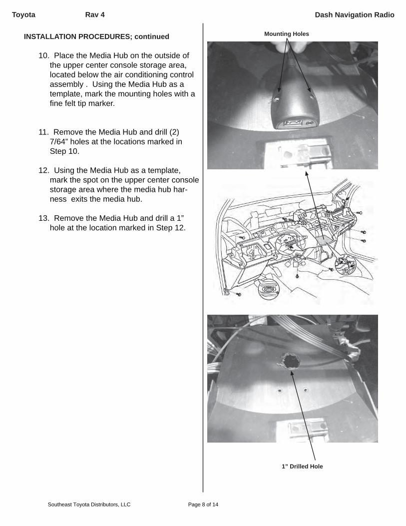
10. Place the Media Hub on the outside of the upper center console storage area, located below the air conditioning control assembly . Using the Media Hub as a template, mark the mounting holes with a fi ne felt tip marker.
11. Remove the Media Hub and drill (2) 7/64” holes at the locations marked in Step 10.
12. Using the Media Hub as a template, mark the spot on the upper center console storage area where the media hub har-ness exits the media hub.
13. Remove the Media Hub and drill a 1” hole at the location marked in Step 12.
Mounting Holes
1” Drilled Hole
Dash Navigation Radio
Southeast Toyota Distributors, LLC Page 8 of 14
Toyota Rav 4
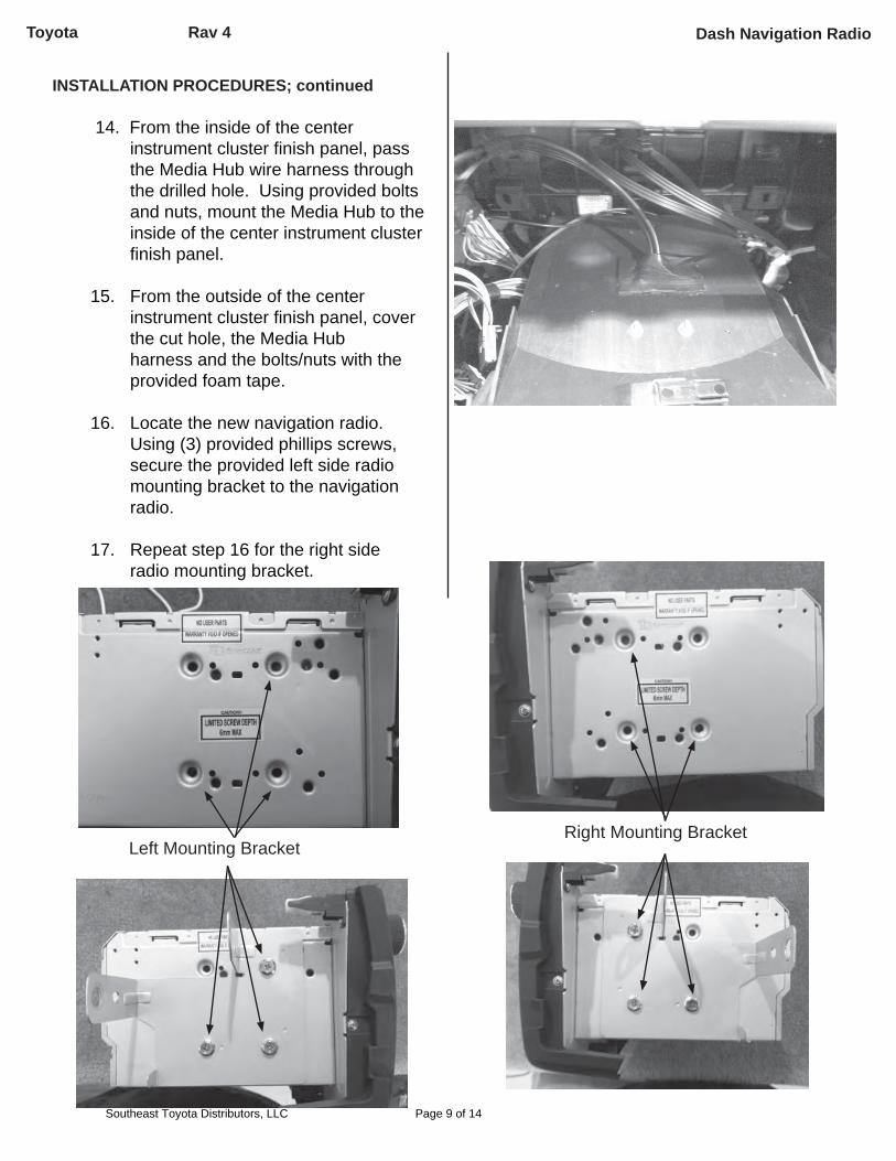
INSTALLATION PROCEDURES; continued
14. From the inside of the center instrument cluster fi nish panel, pass the Media Hub wire harness through the drilled hole. Using provided bolts and nuts, mount the Media Hub to the inside of the center instrument cluster fi nish panel.
15. From the outside of the center instrument cluster fi nish panel, cover the cut hole, the Media Hub harness and the bolts/nuts with the provided foam tape.
16. Locate the new navigation radio. Using (3) provided phillips screws, secure the provided left side radio mounting bracket to the navigation radio. 17. Repeat step 16 for the right side radio mounting bracket.
Left Mounting BracketRight Mounting Bracket
Dash Navigation Radio
Southeast Toyota Distributors, LLC Page 9 of 14
Toyota Rav 4
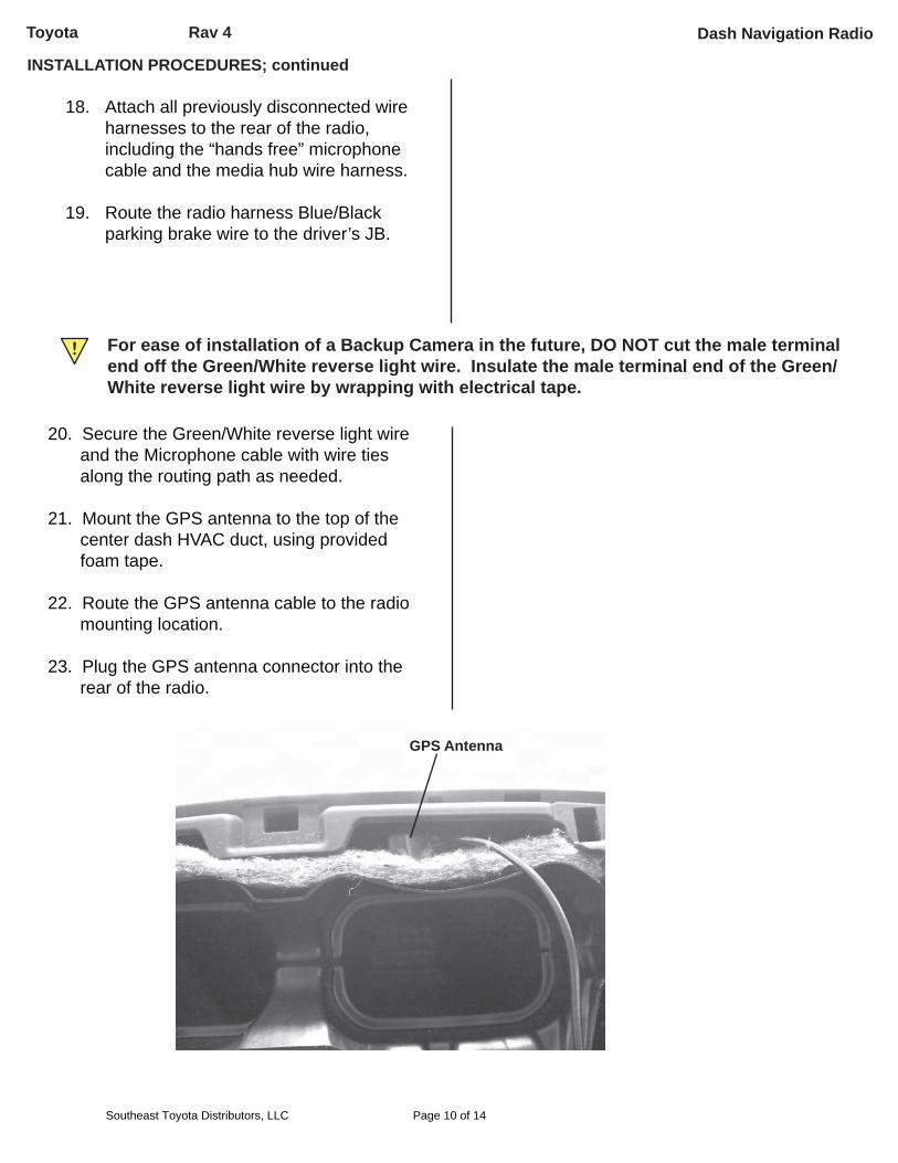
For ease of installation of a Backup Camera in the future, DO NOT cut the male terminal end off the Green/White reverse light wire. Insulate the male terminal end of the Green/White reverse light wire by wrapping with electrical tape.
!
20. Secure the Green/White reverse light wire and the Microphone cable with wire ties along the routing path as needed.
21. Mount the GPS antenna to the top of the center dash HVAC duct, using provided foam tape.
22. Route the GPS antenna cable to the radio mounting location.
23. Plug the GPS antenna connector into the rear of the radio.
GPS Antenna
INSTALLATION PROCEDURES; continued
18. Attach all previously disconnected wire harnesses to the rear of the radio, including the “hands free” microphone cable and the media hub wire harness.
19. Route the radio harness Blue/Black parking brake wire to the driver’s JB.
Dash Navigation Radio
Southeast Toyota Distributors, LLC Page 10 of 14
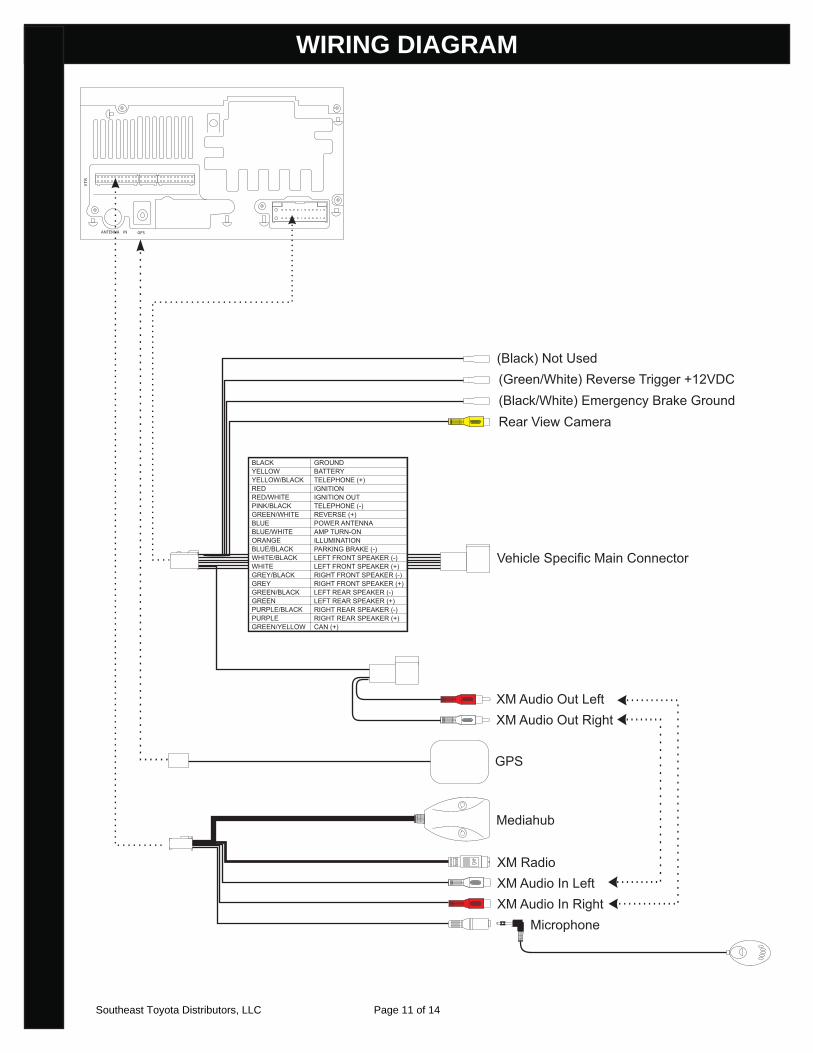
Toyota Rav 4 2012>>WIRING DIAGRAM
ANTENNA IN
VT
R
GPS
Rear View Camera
BLACKYELLOWYELLOW/BLACKREDRED/WHITEPINK/BLACKGREEN/WHITEBLUEBLUE/WHITEORANGEBLUE/BLACKWHITE/BLACKWHITEGREY/BLACKGREYGREEN/BLACKGREENPURPLE/BLACKPURPLEGREEN/YELLOW
GROUNDBATTERYTELEPHONE (+)IGNITIONIGNITION OUTTELEPHONE (-)REVERSE (+)POWER ANTENNAAMP TURN-ONILLUMINATIONPARKING BRAKE (-)LEFT FRONT SPEAKER (-)LEFT FRONT SPEAKER (+)RIGHT FRONT SPEAKER (-)RIGHT FRONT SPEAKER (+)LEFT REAR SPEAKER (-)LEFT REAR SPEAKER (+)RIGHT REAR SPEAKER (-)RIGHT REAR SPEAKER (+)CAN (+)
XM RadioXM Audio In LeftXM Audio In Right Microphone
XM Audio Out LeftXM Audio Out Right
Mediahub
Vehicle Specific Main Connector
(Green/White) Reverse Trigger +12VDC(Black/White) Emergency Brake Ground
GPS
(Black) Not Used
Southeast Toyota Distributors, LLC Page 11 of 14
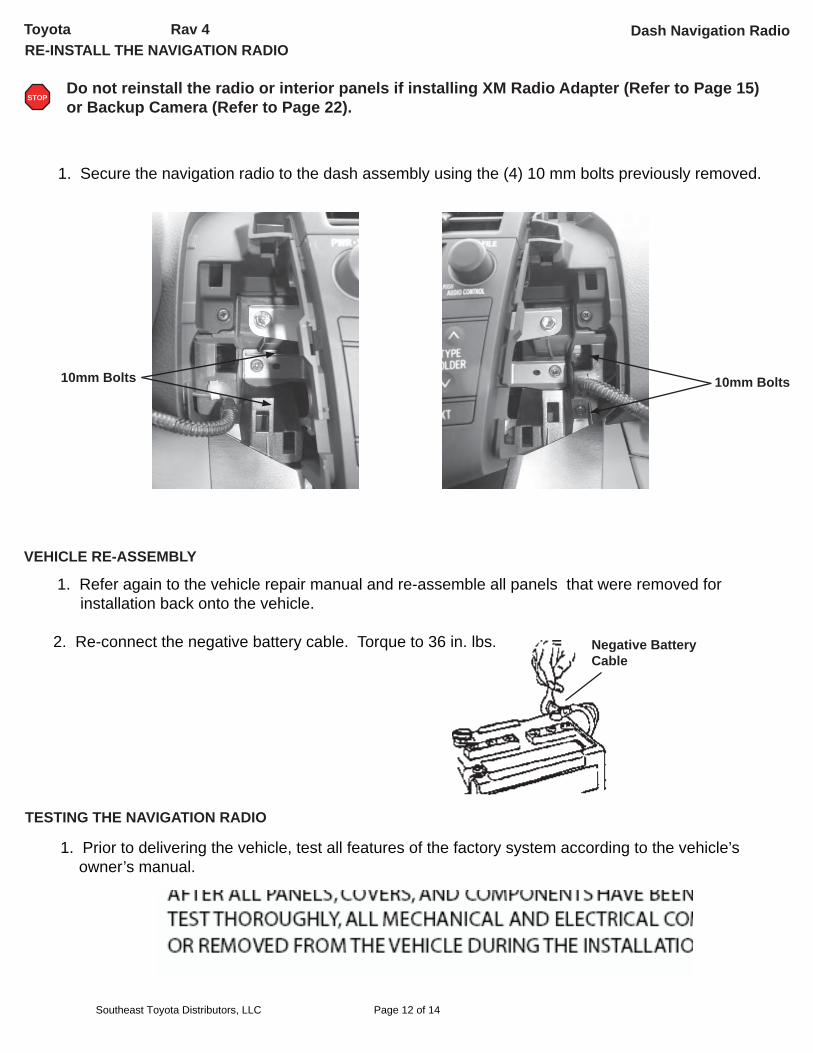
Toyota Rav 4 RE-INSTALL THE NAVIGATION RADIO
1. Secure the navigation radio to the dash assembly using the (4) 10 mm bolts previously removed.
Do not reinstall the radio or interior panels if installing XM Radio Adapter (Refer to Page 15) or Backup Camera (Refer to Page 22).
STOP
VEHICLE RE-ASSEMBLY
1. Refer again to the vehicle repair manual and re-assemble all panels that were removed for installation back onto the vehicle.
2. Re-connect the negative battery cable. Torque to 36 in. lbs. Negative Battery Cable
TESTING THE NAVIGATION RADIO
1. Prior to delivering the vehicle, test all features of the factory system according to the vehicle’s owner’s manual.
10mm Bolts10mm Bolts
Dash Navigation Radio
Southeast Toyota Distributors, LLC Page 12 of 14
Toyota Rav 4
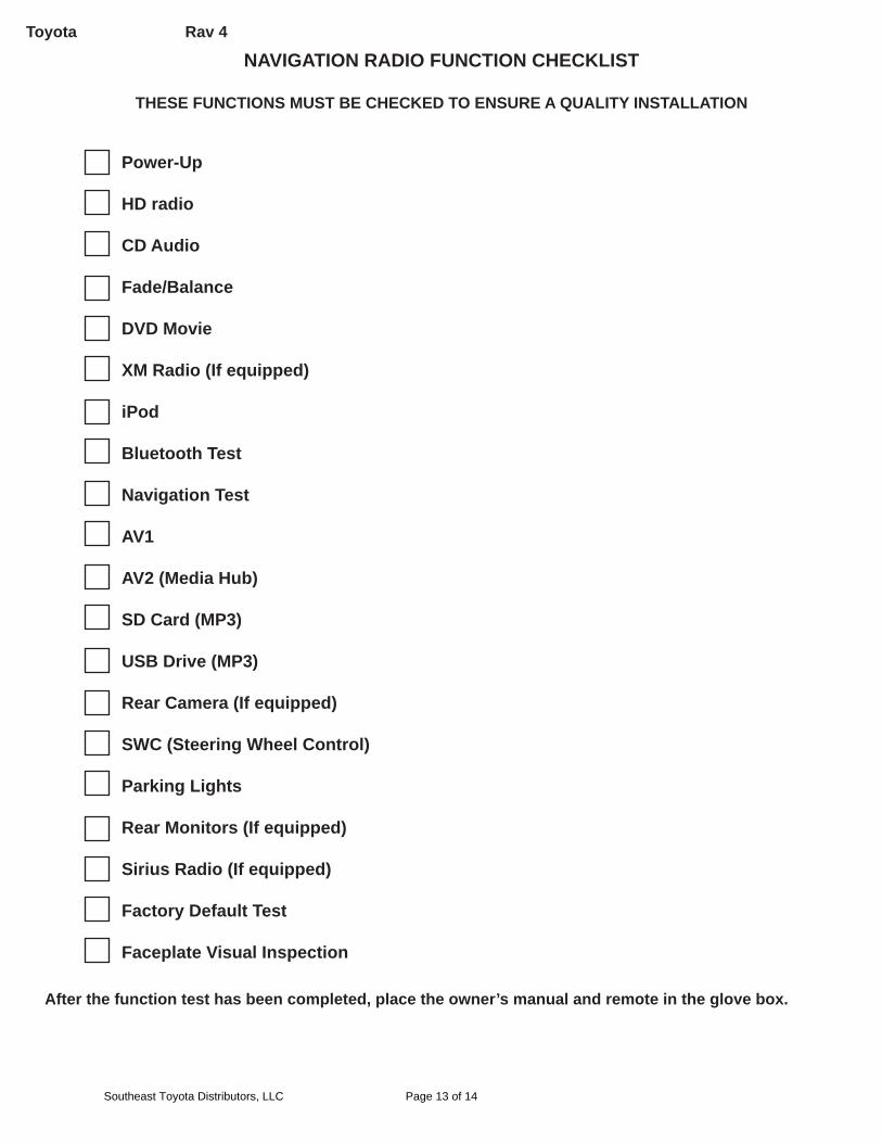
NAVIGATION RADIO FUNCTION CHECKLIST
THESE FUNCTIONS MUST BE CHECKED TO ENSURE A QUALITY INSTALLATION
Power-Up
HD radio
CD Audio
Fade/Balance
DVD Movie
XM Radio (If equipped)
iPod
Bluetooth Test
Navigation Test
AV1
AV2 (Media Hub)
SD Card (MP3)
USB Drive (MP3)
Rear Camera (If equipped)
SWC (Steering Wheel Control)
Parking Lights
Rear Monitors (If equipped)
Sirius Radio (If equipped)
Factory Default Test
Faceplate Visual Inspection
After the function test has been completed, place the owner’s manual and remote in the glove box.
Southeast Toyota Distributors, LLC Page 13 of 14
Toyota Rav 4
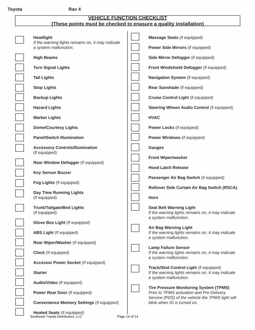
VEHICLE FUNCTION CHECKLIST(These points must be checked to enasure a quality installation)
HeadlightIf the warning lights remains on, it may indicate a system malfunction.
High Beams
Turn Signal Lights
Tail Lights
Stop Lights
Backup Lights
Hazard Lights
Marker Lights
Dome/Courtesy Lights
Panel/Switch Illumination
Accessory Controls/Illumination(If equipped)
Rear Window Defogger (If equipped)
Key Sensor Buzzer
Fog Lights (If equipped)
Day Time Running Lights(If equipped)
Trunk/Tailgate/Bed Lights(If equipped)
Glove Box Light (If equipped)
ABS Light (If equipped)
Rear Wiper/Washer (If equipped)
Clock (If equipped)
Accessor Power Socket (If equipped)
Starter
Audio/Video (If equipped)
Power Rear Door (If equipped)
Convenience Memory Settings (If equipped)
Heated Seats (If equipped)
Massage Seats (if equipped)
Power Side Mirrors (if equipped)
Side Mirror Defogger (if equipped)
Front Windshield Defogger (if equipped)
Navigation System (if equipped)
Rear Sunshade (if equipped)
Cruise Control Light (if equipped)
Steering Wheen Audio Control (if equipped)
HVAC
Power Locks (if equipped)
Power Windows (if equipped)
Gauges
Front Wiper/washer
Hood Latch Release
Passenger Air Bag Switch (if equipped)
Rollover Side Curtain Air Bag Switch (RSCA)
Horn
Seat Belt Warning LightIf the warning lights remains on, it may indicate a system malfunction.
Air Bag Warning LightIf the warning lights remains on, it may indicate a system malfunction.
Lamp Failure SensorIf the warning lights remains on, it may indicate a system malfunction.
Track/Skid Control Light (if equipped)If the warning lights remains on, it may indicate a system malfunction.
Tire Pressure Monitoring System (TPMS)Prior to TPMS activation and Pre-Delivery Service (PDS) of the vehicle the TPMS light will blink when IG is turned on.
Southeast Toyota Distributors, LLC Page 14 of 14