Embed Size (px)
Citation preview
1
Toyota Production System (Textbook)
Chubu-Gakuin University School of Business Administration
Hideo Kunisawa
2
Table of Contents
1. The Concept of the Toyota Production System ............................................................................................. 3 1.1 The Importance of Cost Reduction.......................................................................................................... 3 1.2 The Basic Concepts of the Toyota Production System............................................................................ 4 1.3 Awareness of Muda (Waste) .................................................................................................................... 5 1.4 The Types of Muda (Waste)..................................................................................................................... 7 1.5 Efficiency and Corporate Efficiency ....................................................................................................... 8 1.6 The Two Pillars of the Toyota Production System .................................................................................. 9
2. Just-in-Time................................................................................................................................................. 10 2.1 Heijunka (Leveled Production) ............................................................................................................. 10 2.2 Basic Principles of Just-in-Time............................................................................................................ 12 2.3 Jidoka (Automation with a Human Touch) ........................................................................................... 13 2.4 Means of Assisting Jidoka ..................................................................................................................... 14 2.5 Kanban (Signaling System Using Signs) .............................................................................................. 15 2.6 Kanban Rules ........................................................................................................................................ 18 2.7 Conveyance ........................................................................................................................................... 24
3. Standardized Work....................................................................................................................................... 25 3.1 Standardized Work................................................................................................................................. 25 3.2 Principle of Standardized In-process Stock........................................................................................... 26 3.3 Standardized Work and Kaizen (Continuous Improvement) ................................................................. 27 3.4 Main Points for Creating Standardized Work........................................................................................ 28
Procedure 1: Creation of Process Capacity Sheet.................................................................................... 28 Procedure 2: Creation of Standardized Work Combination Table........................................................... 31 Procedure 3: Creation of Standardized Work Chart................................................................................. 34
3.5 Elemental Work Analysis ...................................................................................................................... 35 3.6 Work Kaizen and Equipment Kaizen ..................................................................................................... 38 3.7 Points of Focus in Work Kaizen ............................................................................................................ 39 3.8 Principles of Motion Economy.............................................................................................................. 40
3
1. The Concept of the Toyota Production System 1.1 The Importance of Cost Reduction
(1) The necessity of cost reduction
- It is important to earn a profit, perpetually prosper, and strive to improve our daily lives while also nurturing harmony with society. Cost reduction is promoted in order to achieve these objectives.
(2) Selling price and cost
Selling price = cost + profit Demand > Supply In this case, cost basis is acceptable (Seller’s market)
Profit = selling price – cost Demand < Supply Cost reduction is necessary (Buyer’s market)
- Raise the selling price … The selling price is determined by the actual conditions in the market Market competition is severe and this is often difficult
- Lower the cost … Cost reduction increases the profit greatly
It is possible to reduce the cost through effort
4
1.2 The Basic Concepts of the Toyota Production System
“Thoroughly eliminate muda (waste) and make things with efficient just-in-time production” (1) The aims of the Toyota Production System
[1] Thoroughly eliminate muda and strive to reduce the cost of production [2] Make it easy to ensure and guarantee manufacturing quality [3] Create a workplace in which all members can fully exercise their capabilities, and which is
founded on respect for humanity, trust, and mutual support [4] Create genba (work sites) that are able to respond quickly and flexibly to the changes in the fluid
marketplace
(2) The way of making things and cost - Cost is controlled by the way that things are made and the way that the work is performed. The
technology of the way of making things is called manufacturing technology
Cost basis cannot be applied The selling price is determined by the actual conditions in the market If profits are not increased, then corporate activity will not be viable
- Investigate the way of making things from a variety of different angles, thoroughly eliminate muda,
and reduce the cost of production
5
1.3 Awareness of Muda (Waste)
Muda is “an element of production that only increases cost”. (1) Movement and work
Work = shigoto + muda Shigoto (value-adding work) is any process that increases the added value
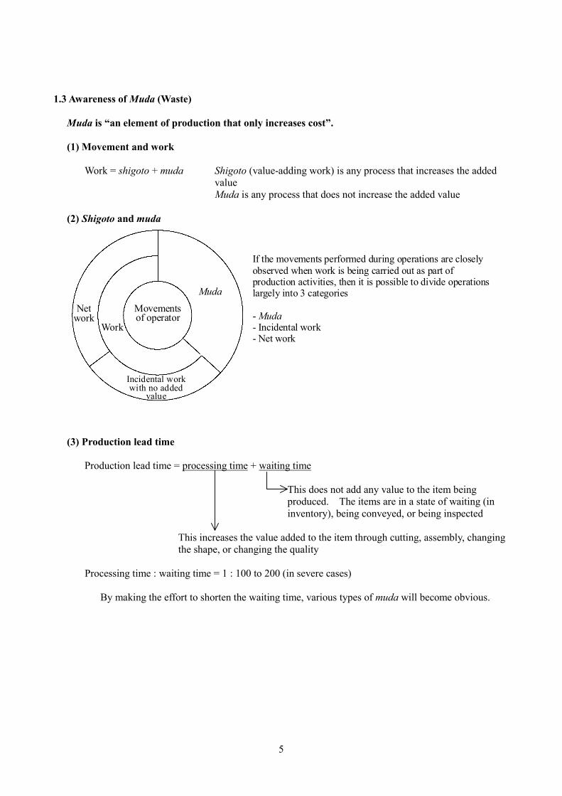
Muda is any process that does not increase the added value (2) Shigoto and muda
Net work
Work
If the movements performed during operations are closely observed when work is being carried out as part of production activities, then it is possible to divide operations largely into 3 categories - Muda - Incidental work - Net work
Movements of operator
Muda
Incidental work with no added
value
(3) Production lead time
Production lead time = processing time + waiting time
This does not add any value to the item being produced. The items are in a state of waiting (in inventory), being conveyed, or being inspected
This increases the value added to the item through cutting, assembly, changing the shape, or changing the quality
Processing time : waiting time = 1 : 100 to 200 (in severe cases)
By making the effort to shorten the waiting time, various types of muda will become obvious.
6
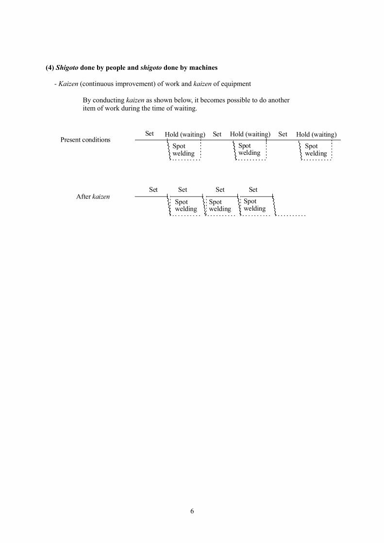
(4) Shigoto done by people and shigoto done by machines
- Kaizen (continuous improvement) of work and kaizen of equipment
By conducting kaizen as shown below, it becomes possible to do another item of work during the time of waiting.
Set Set Set
Set Set Set Set
Present conditions
After kaizen
Hold (waiting) Hold (waiting) Hold (waiting)
Spot welding
Spot welding
Spot welding
Spot welding
Spot welding
Spot welding
7
1.4 The Types of Muda (Waste)
(1) The types of muda
- Muda of overproduction [1] Consumption of materials and parts - Muda of inventory [2] Wasted energy from electricity, air, and oil, etc. - Muda of waiting [3] Increase in the number of pallets and boxes, etc. - Muda in motion [4] Increase in conveyance vehicles and lifting machines - Muda in conveyance [5] Establishment of new storage areas and warehouses - Muda of correction [6] Increase in machines and man-hours to manage inventory - Muda in processing itself [7] Other
(2) Muda created by overproduction
- Problematic points in the production process and muda become hidden - By eliminating muda due to overproduction, the problematic points and muda become obvious - The muda from overproduction creates all the other types of muda and has a large influence on
corporate efficiency (3) The reasons that overproduction occurs
[1] Abnormalities such as breakdowns of machinery, defects, absence of operators, and other changes, etc.
[2] There are many operators Safeguards for “just in case something happens,” a proper operational balance is not being maintained The relationship with the company is thought of as contractual
[3] Variations in the amount of load [4] Production is poorly structured
Way of combining processes and lot production [5] Increases in mistaken rates of operation and increases in apparent efficiencies [6] Thinking that it is wrong to stop the production line
8
1.5 Efficiency and Corporate Efficiency
(1) Efficiency and corporate efficiency
Efficiency and corporate efficiency are different. Even if efficiency is improved, corporate efficiency cannot be allowed to decrease. Production of the required number of units is the main prerequisite for improving corporate efficiency.
- Improving efficiency will have meaning for the first time when it is tied to cost reduction - In order for this to be achieved, it is necessary to promote the concept of producing the necessary
items with the fewest people possible (2) True efficiency and apparent efficiency
Improvement of apparent efficiency will not lead to cost reduction Improvement of efficiency becomes useful when it is tied to cost reduction
- Improvement of apparent efficiency
Normal: 100 units made by 10 people Kaizen: 120 units made by 10 people
20% improvement in efficiency
- Improvement of true efficiency
Normal:100 units made by 10 people Kaizen: 100 units made by 8 people
20% improvement in efficiency
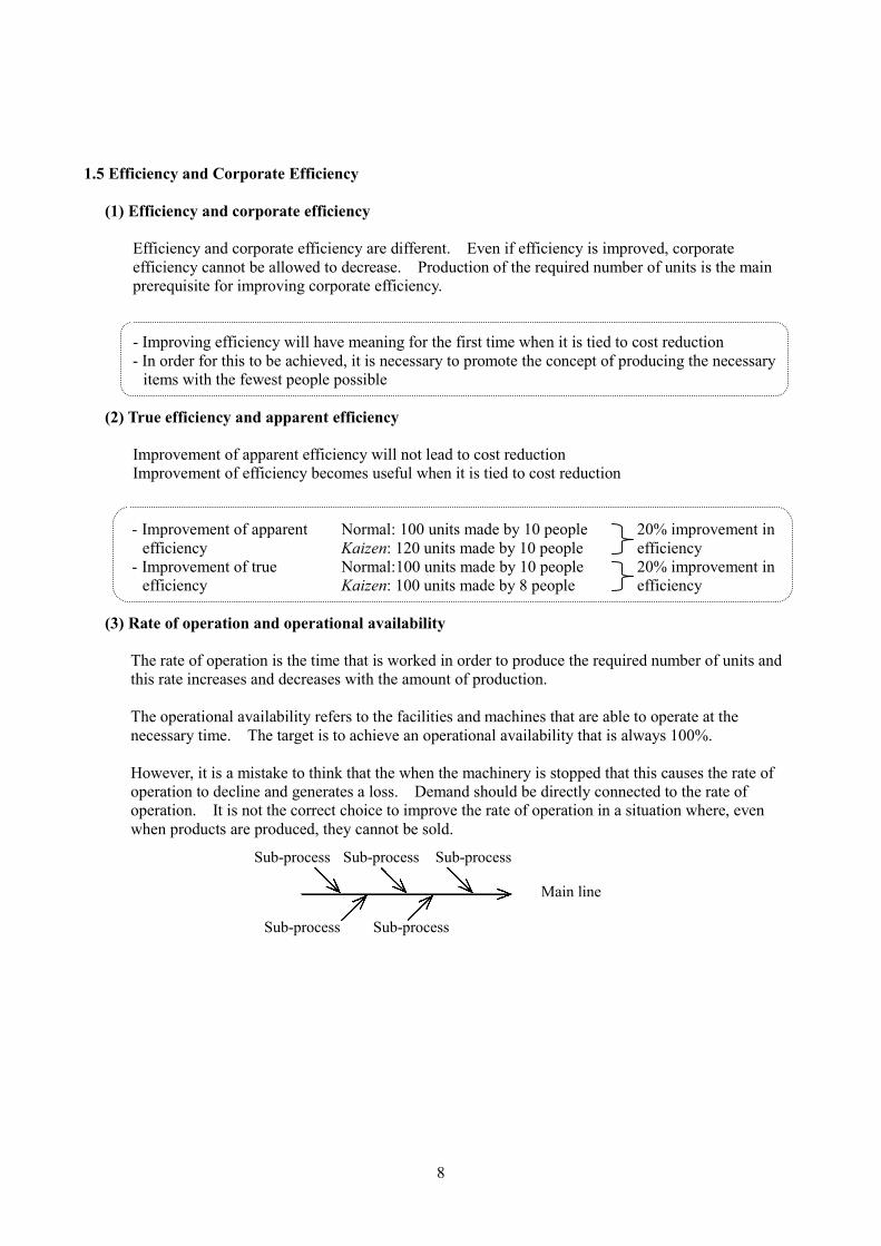
(3) Rate of operation and operational availability
The rate of operation is the time that is worked in order to produce the required number of units and this rate increases and decreases with the amount of production. The operational availability refers to the facilities and machines that are able to operate at the necessary time. The target is to achieve an operational availability that is always 100%. However, it is a mistake to think that the when the machinery is stopped that this causes the rate of operation to decline and generates a loss. Demand should be directly connected to the rate of operation. It is not the correct choice to improve the rate of operation in a situation where, even when products are produced, they cannot be sold.
Sub-process Sub-process Sub-process
Sub-process Sub-process
Main line
9
1.6 The Two Pillars of the Toyota Production System
(1) The two pillars of the Toyota Production System
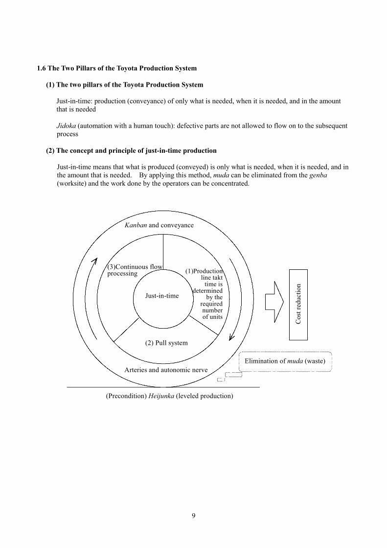
Just-in-time: production (conveyance) of only what is needed, when it is needed, and in the amount that is needed
Jidoka (automation with a human touch): defective parts are not allowed to flow on to the subsequent process
(2) The concept and principle of just-in-time production
Just-in-time means that what is produced (conveyed) is only what is needed, when it is needed, and in the amount that is needed. By applying this method, muda can be eliminated from the genba (worksite) and the work done by the operators can be concentrated.
Kanban and conveyance
(3)Continuous flow processing (1)Production
line takttime is
determinedby the
requirednumberof units
Just-in-time
(2) Pull system
Arteries and autonomic nerve Elimination of muda (waste)
(Precondition) Heijunka (leveled production)
Cos
t red
uctio
n
10
2. Just-in-Time 2.1 Heijunka (Leveled Production)
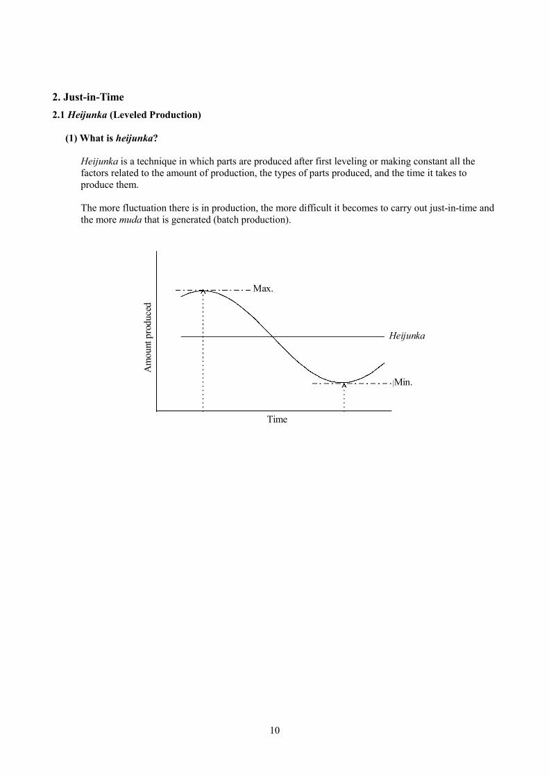
(1) What is heijunka?
Heijunka is a technique in which parts are produced after first leveling or making constant all the factors related to the amount of production, the types of parts produced, and the time it takes to produce them. The more fluctuation there is in production, the more difficult it becomes to carry out just-in-time and the more muda that is generated (batch production).
Am
ount
pro
duce
d
Heijunka
Time
Max.
Min.
11
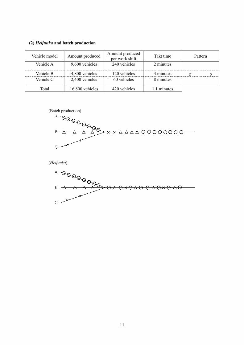
(2) Heijunka and batch production
Vehicle model Amount produced Amount produced per work shift Takt time Pattern
Vehicle A 9,600 vehicles 240 vehicles 2 minutes Vehicle B 4,800 vehicles 120 vehicles 4 minutes r r Vehicle C 2,400 vehicles 60 vehicles 8 minutes
Total 16,800 vehicles 420 vehicles 1.1 minutes
(Batch production)
(Heijunka)
12
2.2 Basic Principles of Just-in-Time Production (conveyance) of only what is needed, when it is needed, and in the amount that is needed (1) The production line takt time is determined by the required number of units
- The required parts are produced at the required speed and only in the required amount - The required number of parts to be produced will change according to demand - Production shall be tied to demand
(2) Pull system
- The production plan is indicated to the final process. In the production line, the subsequent processes go to the preceding process and pull only the amount of parts that they will use. The preceding processes then produce only the amount of parts that were pulled.
(3) Continuous flow processing
- The processes are collected together so that each individual piece proceeds from one process to the subsequent process in a continuous flow.
- This is the same for a process composed of many operators as it is for a process run by 1 operator.
Conditions of continuous flow production:
Multi-skill development of operators
Equipment is lined up in the process order Pieces flow down the line one by one The processes are synchronized
The operator shall handle multiple processes
Work is performed while standing
Multi-process handling and a slim, fast flow:
- If one operator works at a single machine, then there are many in-progress parts in between the processes, there is a lot of in-process stock, and the lead time becomes long.
- By using single-piece flow with multi-process handling, the progress of the parts is fast and the lead
time becomes shorter.
13
2.3 Jidoka (Automation with a Human Touch)
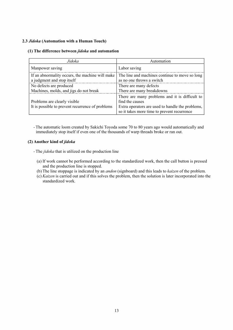
(1) The difference between jidoka and automation
Jidoka Automation Manpower saving Labor saving
If an abnormality occurs, the machine will make a judgment and stop itself
The line and machines continue to move so long as no one throws a switch
No defects are produced Machines, molds, and jigs do not break
There are many defects There are many breakdowns
Problems are clearly visible It is possible to prevent recurrence of problems
There are many problems and it is difficult to find the causes Extra operators are used to handle the problems, so it takes more time to prevent recurrence
- The automatic loom created by Sakichi Toyoda some 70 to 80 years ago would automatically and immediately stop itself if even one of the thousands of warp threads broke or ran out.
(2) Another kind of jidoka
- The jidoka that is utilized on the production line
(a) If work cannot be performed according to the standardized work, then the call button is pressed and the production line is stopped.
(b) The line stoppage is indicated by an andon (signboard) and this leads to kaizen of the problem. (c) Kaizen is carried out and if this solves the problem, then the solution is later incorporated into the
standardized work.
14
2.4 Means of Assisting Jidoka
(1) Poka-yoke (fool-proofing)
- This refers to production in which defective parts are not produced. The poka-yoke mechanisms build in quality during the production processes and do not allow defective parts to be sent on to the subsequent process. Consequently, work mistakes, injuries, defects, and many other problems are naturally eliminated without having to pay close attention to each issue individually.
(2) Fixed-position stop system
- If an operator feels that they have fallen behind in their work for any reason and they send a line stop signal, the production line will always stop in the same place.
(3) Visual controls (andon)
- It is important to immediately alert someone if a problem occurs during work. The andon system is a management tool that allows the line managers and supervisors to understand the content of a problem that they want to know about.
15
2.5 Kanban (Signaling System Using Signs)
(1) The role of kanban: To prevent overproduction muda
1. Production and conveyance instruction information - On the kanban the part name, amount to be produced (time), sequence, and destination that it will
be conveyed to are all written down. Therefore, it is easy to understand what to produce, how much of it to produce, by when it should be produced, and then where it should be conveyed to.
2. Visual controls
a. Inhibiting overproduction It is not possible to produce an excess amount The order of production priority is understood
b. Detecting the progress or delay of a process
The process can be controlled easily - Strict compliance with standardized
work - State of progress of the subsequent
process - Grasp the ability to build in quality in
your process - Urgency of the subsequent process
- Status of inventory in your process - Order of priority for the work in your process
3. A tool for process kaizen and work kaizen
- Hidden problems are identified by reducing the number of kanban
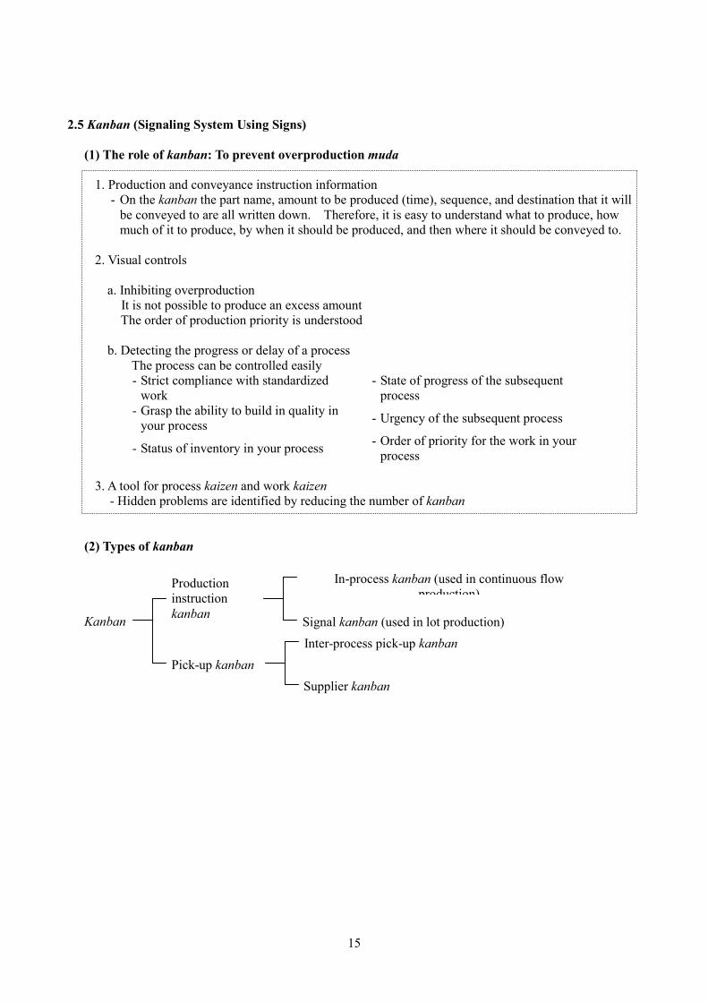
(2) Types of kanban Kanban
Production instruction kanban
Pick-up kanban
In-process kanban (used in continuous flow production)
Signal kanban (used in lot production) Inter-process pick-up kanban
Supplier kanban
16
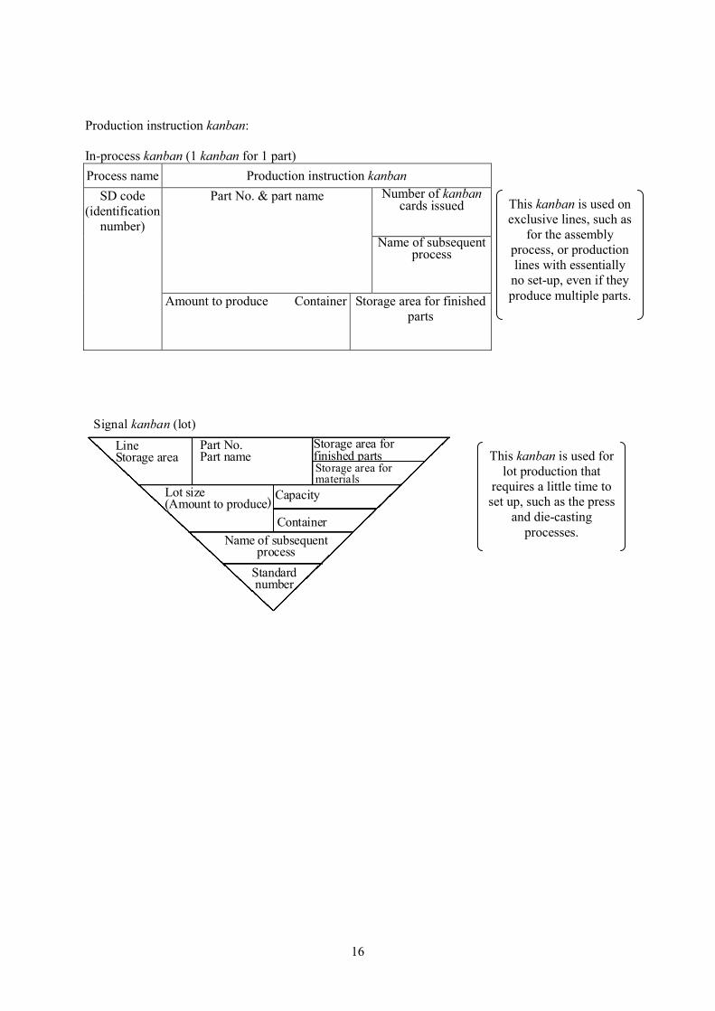
Production instruction kanban: In-process kanban (1 kanban for 1 part) Process name Production instruction kanban
Number of kanban cards issued
Part No. & part name
Name of subsequent process
SD code (identification
number)
Amount to produce Container
Storage area for finished parts
Signal kanban (lot)
Line Storage area
Part No. Part name
Name of subsequent process
Lot size (Amount to produce)
Storage area for materials
Storage area for finished parts
Standard number
Container
Capacity
This kanban is used on exclusive lines, such as
for the assembly process, or production lines with essentially
no set-up, even if they produce multiple parts.
This kanban is used for lot production that
requires a little time to set up, such as the press
and die-casting processes.
17
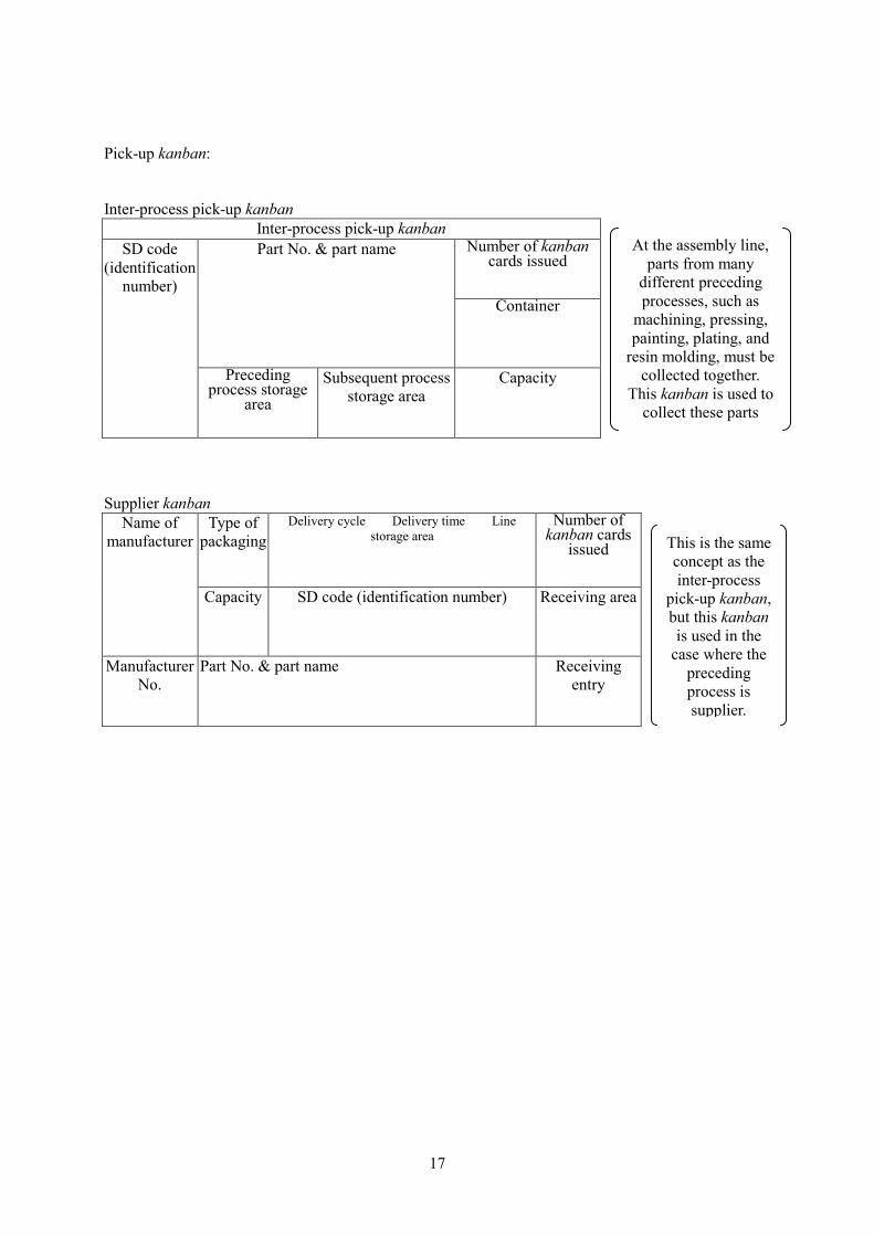
Pick-up kanban: Inter-process pick-up kanban
Inter-process pick-up kanban Number of kanban
cards issued
Part No. & part name
Container
SD code (identification
number)
Preceding process storage
area
Subsequent process storage area
Capacity
Supplier kanban
Type of packaging
Delivery cycle Delivery time Line storage area
Number of kanban cards
issued
Name of manufacturer
Capacity SD code (identification number) Receiving area
Manufacturer No.
Part No. & part name Receiving entry
At the assembly line, parts from many
different preceding processes, such as
machining, pressing, painting, plating, and
resin molding, must be collected together.
This kanban is used to collect these parts
This is the same concept as the inter-process
pick-up kanban, but this kanban is used in the
case where the preceding process is supplier.
18
2.6 Kanban Rules
(1) Rules for production instruction kanban
[1] Parts are produced only in the amount of kanban that have been withdrawn and in the same order that the kanban were withdrawn.
[2] The part and its corresponding kanban must always flow down the line together. [3] Parts that do not have a kanban are absolutely never produced.
(2) Rules for pick-up kanban
[1] If you are the first person to place your hands on the first of the parts containers, withdraw the
kanban. [2] Take the kanban that was withdrawn to the preceding process to pull the necessary part. [3] At the store where you pull the part, replace the in-process kanban with the kanban you brought
with you. [4] Parts that do not have a kanban are absolutely never conveyed.
(3) Additional points to pay attention to when operating a kanban system
[1] The size of the lots assigned to a single kanban shall be as small as possible. [2] The necessary number of kanban cards shall never exceed what is required. [3] Kanban shall be put out as diligently as possible and also collected as diligently as possible. [4] Consider 100% as non-defective parts
19
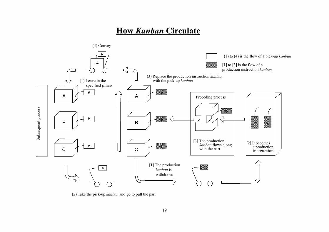
Preceding process How Kanban Circulate
(1) to (4) is the flow of a pick-up kanban
[1] to [3] is the flow of a production instruction kanban
(4) Convey
Subs
eque
nt p
roce
ss
(3) Replace the production instruction kanban with the pick-up kanban
[1] The production kanban is withdrawn
Preceding process
(2) Take the pick-up kanban and go to pull the part
(1) Leave in the specified place
[2] It becomes a production instruction
[3] The production kanban flows along with the part
20
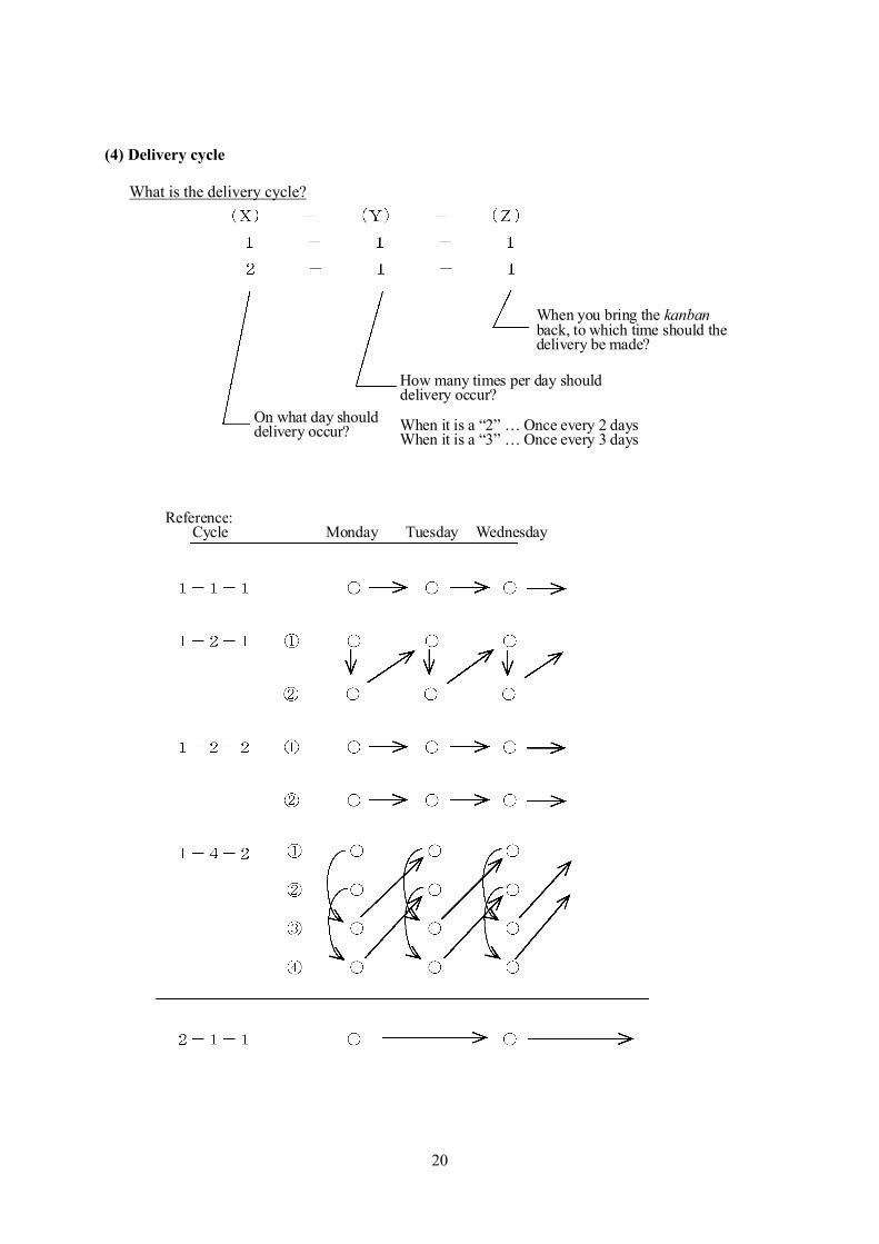
(4) Delivery cycle
What is the delivery cycle?
On what day should delivery occur?
How many times per day should delivery occur? When it is a “2” … Once every 2 days When it is a “3” … Once every 3 days
When you bring the kanban back, to which time should the delivery be made?
Reference: Cycle Monday Tuesday Wednesday
21
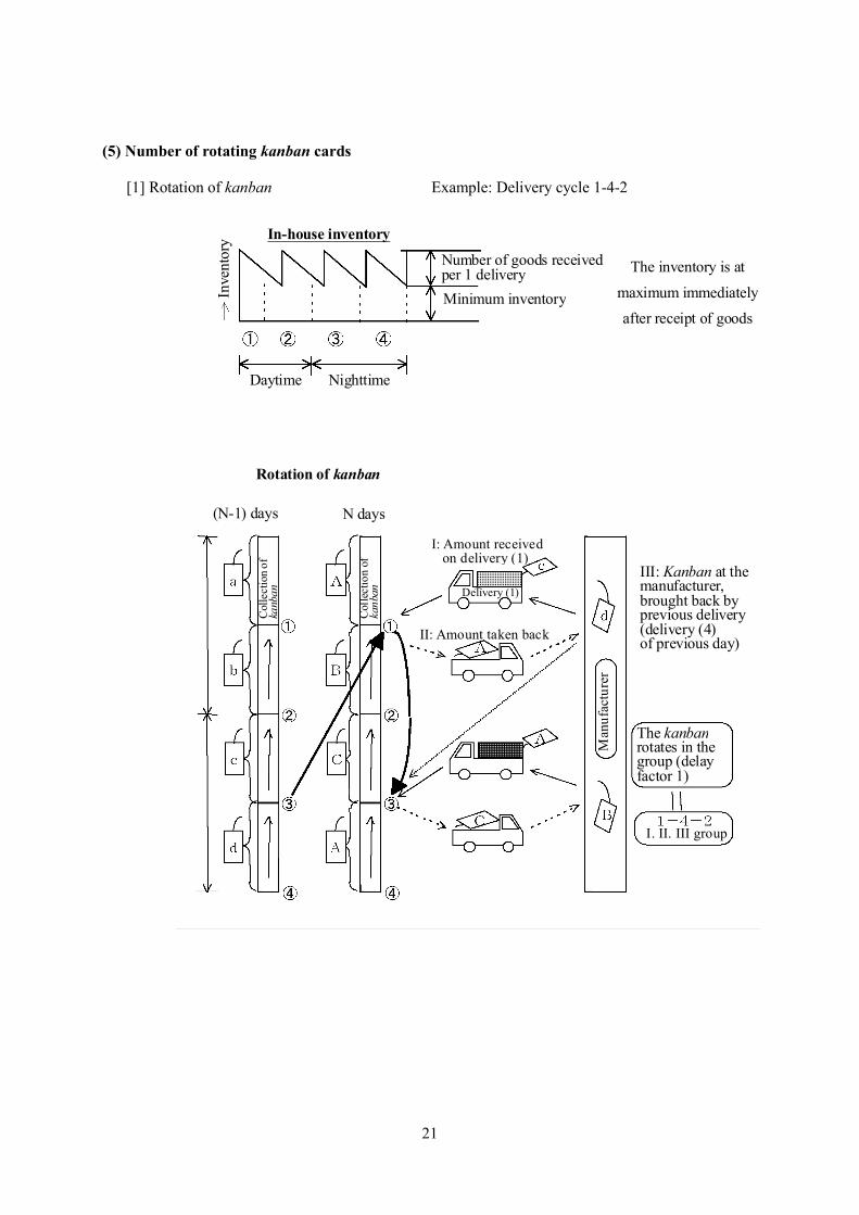
(5) Number of rotating kanban cards
[1] Rotation of kanban Example: Delivery cycle 1-4-2
In-house inventory In
vent
ory
Daytime Nighttime
Number of goods received per 1 delivery The inventory is at
maximum immediately
after receipt of goods Minimum inventory
Rotation of kanban
(N-1) days N days
Col
lect
ion
of
kanb
an
Col
lect
ion
of
kanb
an
I. II. III group
The kanban rotates in the group (delay factor 1)
I: Amount received on delivery (1)
Delivery (1)
II: Amount taken back
III: Kanban at the manufacturer, brought back by previous delivery (delivery (4) of previous day)
Man
ufac
ture
r

22
(2) Calculation step for the number of rotating kanban cards
Example: Find the number of rotating kanban cards (safety value is 0.2 per day) if a parts container holds 10 parts and 120 parts are used in 1 day.
In the case of a 1- 4- 2 delivery cycle:
a) The number of kanban cards used in 1 day:
Number of parts used per day / number of parts per container = 120/10 = 12 kanban cards per day Þ A b) The number of goods received per 1 delivery:
A/y = 12/4 = 3 kanban cards per 1 delivery Þ B
c) Kanban group: (z + 1) ´ B = (2 + 1) ´ 3 = 9 kanban cards Þ C d) Safety inventory: A ´ 0.2 = 2.4 ® 3 kanban cards (currently this is rounded up) Þ D e) Number of rotating kanban cards: C + D = 9 + 3 = 12 cards f) (Reference) Maximum and minimum inventory: Maximum inventory is B + D = 3 + 3 = 6
Minimum inventory is D = 3 (3) Equation
Number of rotating kanban cards ={ }
containerper parts ofNumber
ueSafety val y
1 zxdayper used parts ofNumber þýü
îíì
++´´
x y z
23
Example calculation of the number of rotating kanban cards:
- Delivery cycle : 1-4-2 - Necessary number of parts
per work shift : 320/shift - Number of parts per container : 20/container - Safety factor : 0.2 per day
What is the number of rotating kanban cards?
24
2.7 Conveyance
(1) Inter-process conveyance - In order to realize just-in-time production, it is necessary to convey the parts in a timely manner
between production processes that are separated so that production can be carried out smoothly. (2) Conditions of inter-process conveyance
[1] Collection of information a little at a time : frequent conveyance [2] Pulling of different parts in a variety of small amounts : mixed-load conveyance [3] Pulling from line-side part storage areas : frequent conveyance and direct
conveyance (3) Inter-process conveyance methods
(a) Conveyance of fixed amounts at irregular times In this method, at the time that the subsequent process has used up a fixed amount of parts they then go to the preceding process to pull more parts and the amount of parts that are consumed is standardized.
(b) Conveyance of irregular amounts at fixed times
The concept is the same as for conveyance of fixed amounts at irregular times. This is a conveyance method used to standardize the elapsed time.
25
3. Standardized Work 3.1 Standardized Work
(1) What is standardized work?
- In the Toyota Production System this is the foundation of the way that parts are produced, kaizen, and the way the system is managed, etc.
- Standardized work is a means of determining the way that shigoto (value-adding work) shall be performed so that high quality products can be produced safely and inexpensively.
(2) Conditions of standardized work
[1] Centered on the movements of people [2] Repetitive work
(3)The 3 elements of standardized work
1. Takt time - This is the amount of time in which 1 vehicle or 1 part must be produced 2. Working sequence - In the case where parts are processed or assembled, this is the sequence of operations that an
operator performs, such as conveying parts, placing parts in machines, and removing parts from machines, in order to assemble a part.
3. Standard in-process stock - This is the minimum necessary amount of work pieces so that the operator can perform the same
operation repetitively in the same order each time.
26
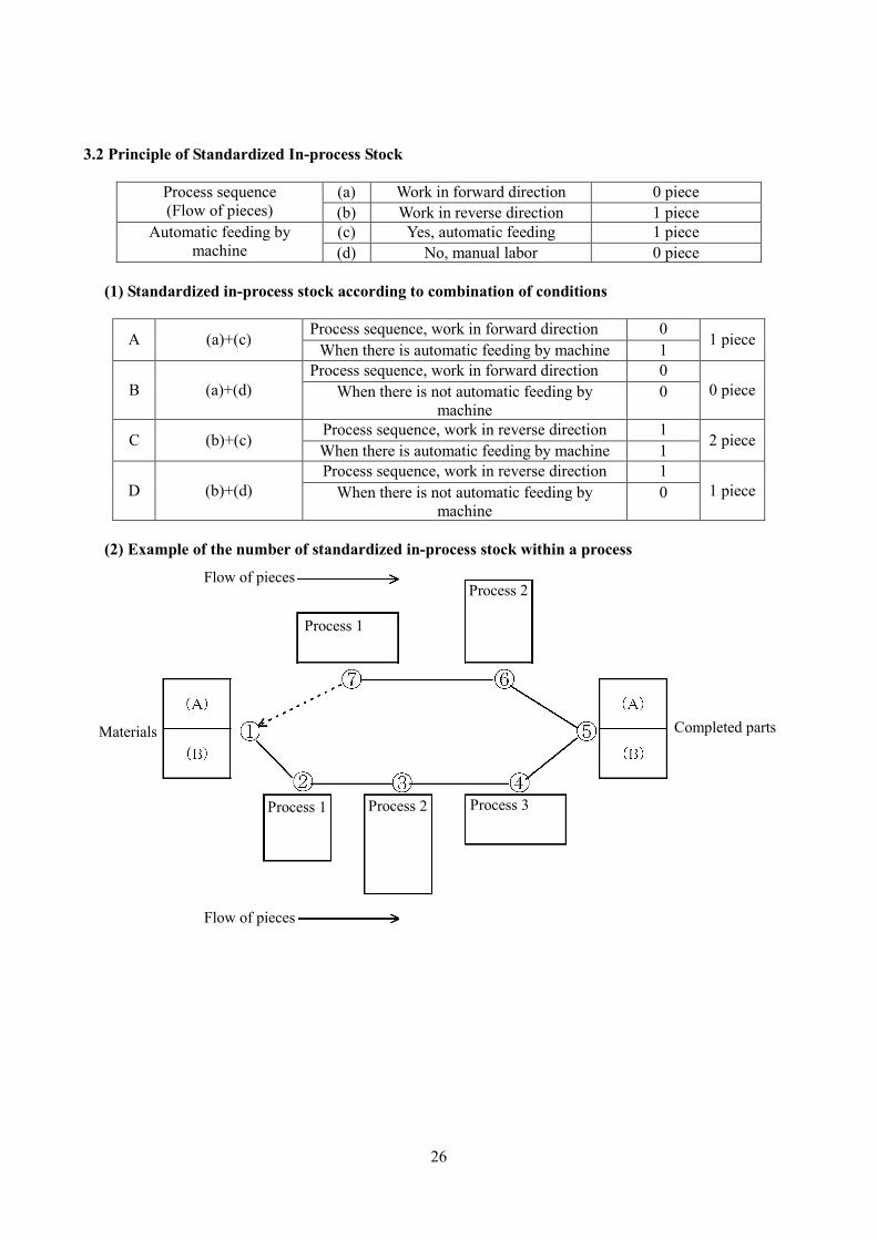
3.2 Principle of Standardized In-process Stock
(a) Work in forward direction 0 piece Process sequence (Flow of pieces) (b) Work in reverse direction 1 piece
(c) Yes, automatic feeding 1 piece Automatic feeding by machine (d) No, manual labor 0 piece
(1) Standardized in-process stock according to combination of conditions
Process sequence, work in forward direction 0 A (a)+(c) When there is automatic feeding by machine 1
1 piece
Process sequence, work in forward direction 0 B (a)+(d) When there is not automatic feeding by
machine 0 0 piece
Process sequence, work in reverse direction 1 C (b)+(c) When there is automatic feeding by machine 1 2 piece
Process sequence, work in reverse direction 1 D (b)+(d) When there is not automatic feeding by
machine 0 1 piece
(2) Example of the number of standardized in-process stock within a process
Flow of pieces
Flow of pieces
Materials Completed parts
Process 1
Process 2
Process 1 Process 2 Process 3
27
3.3 Standardized Work and Kaizen (Continuous Improvement)
“There is no kaizen (continuous improvement) in places where there is no standardization” - “Superficial” standardized work (before kaizen) shows the current situation as it appears on the surface. - Standardized work reflects kaizen and the supervisor integrates their own will into the work, turning it
from “superficial” into true standardized work. (1) Kaizen based on standardized work
[1] Reduction of man-hours [2] Reduction of work-in-process inventory [3] Reduction of quality defects [4] Enhancement of production capacity [5] Layout (organization) [6] Visual controls
(2) Standardized work and work standards
- Work standards are those things that are standardized, such as the way that work is performed and machines are operated, in order to carry out standardized work. The work procedure sheet is a representative example of a work standard.
28
3.4 Main Points for Creating Standardized Work Standardized work is established by determining the following:
1. Takt time 2. Work standards 3. Standardized in-process stock
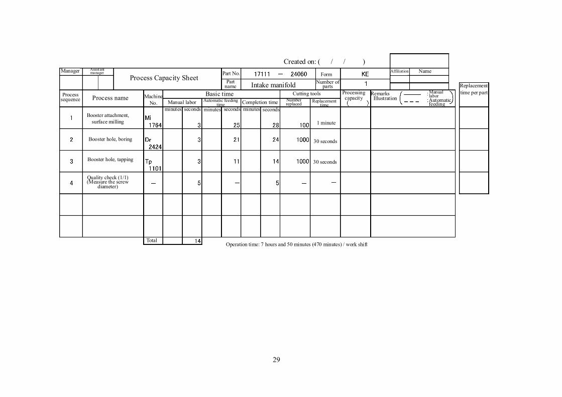
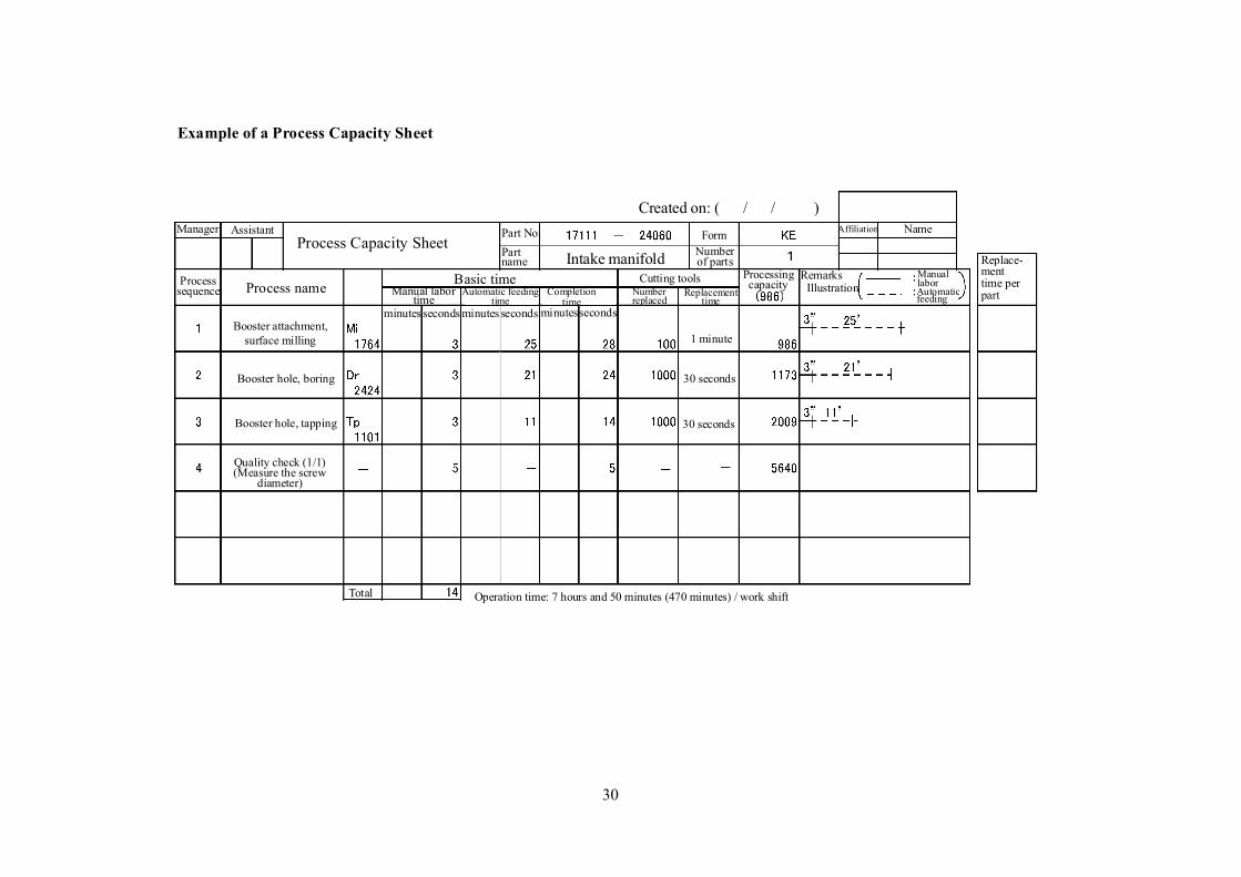
Procedure 1: Creation of Process Capacity Sheet
(1) Process sequence: the number in the sequence of the processing process (2) Process name: Enter the name of the process where the part receives processing
(a) When there are 2 or more machines in the same process that perform the processing, they shall be entered separately.
(b) In the case where 1 machine takes 2 parts or 3 parts, this should also be entered. (c) Work that is conducted regularly with a certain frequency, such as sweeping away grinding
swarf and quality checks, for example, shall also be entered along with their frequency. (3) Machine No.: Enter the machine number (4) Basic time
(a) Manual labor time: The amount of time the operator spends performing manual labor at the machine (process) shall be measured and entered. This does not include walking time.
(b) Automatic feeding time: The amount of time required for the machine to perform processing on the work piece shall be measured and entered.
(c) Completion time: The amount of time necessary for a machine (process) to complete 1 part (or 2 parts in the case where 2 parts are taken). In general: Completion time = manual labor time + automatic feeding time Note 1: In the case of work that is conducted with a certain frequency, the manual labor time
per work piece shall be entered. (5) Cutting tools
(a) Number of cutting tools replaced: Enter for each cutting tool and grinding stone (b) Cutting tool replacement time: Enter for each cutting tool and grinding stone
(6) Processing capacity: Number of parts that can be processed within the fixed time of 1 shift
Processing capacity =piece workper timet replacemen tool cutting piece workper time Completion
shift work a of time Operation+
Note 2: Anything after the decimal point is ignored. When the machine is different, write it
separately
29
Machine No.
Name Assistant manager
Process Capacity Sheet Intake manifold
Created on: ( / / ) Form
Number of parts
Affiliation
Process name Basic time Manual labor
Automatic feeding time
Cutting tools
Completion time
Number replaced Replacement
time Processing capacity Remarks
Illustration Manual labor Automatic feeding
Replacement time per part
Booster attachment,
surface milling
Booster hole, boring
Booster hole, tapping
Quality check (1/1) (Measure the screw
diameter)
seconds seconds minutes minutes minutes seconds
Operation time: 7 hours and 50 minutes (470 minutes) / work shift
Part No. Part
name
Total
Process sequence
Manager
1 minute
30 seconds
30 seconds
30
Name Assistant Process Capacity Sheet
Intake manifold
Created on: ( / / ) Form
Number of parts
Affiliation
Process name Basic time Manual labor
time Automatic feeding time
Cutting tools
Completion
time Number replaced Replacement
time Processing capacity
Remarks Illustration
Manual labor Automatic feeding
Replace- ment time per part
Booster attachment,
surface milling
Booster hole, boring
Booster hole, tapping
Quality check (1/1) (Measure the screw
diameter)
seconds seconds minutes minutes minutes seconds
Operation time: 7 hours and 50 minutes (470 minutes) / work shift
Part No. Part name
Total
Process sequence
Manager
Example of a Process Capacity Sheet
1 minute
30 seconds
30 seconds
31
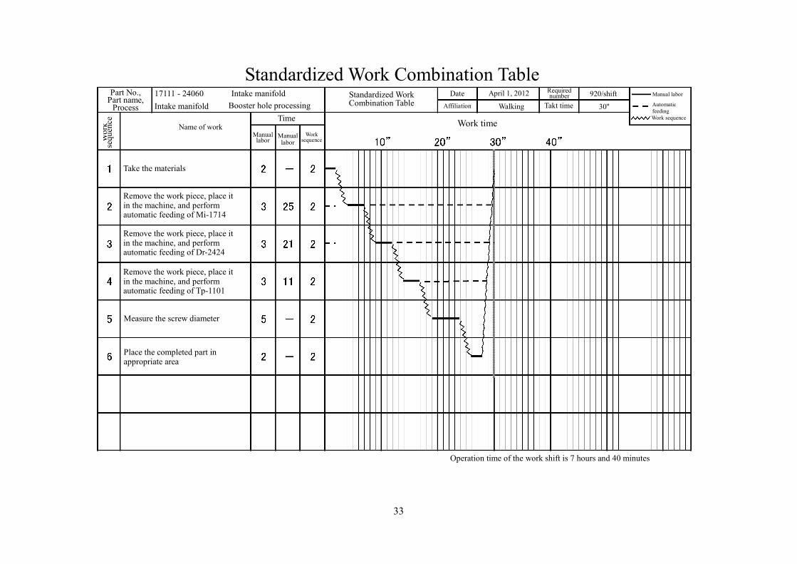
Procedure 2: Creation of Standardized Work Combination Table
(1) Work sequence: The sequence in which work is performed is indicated by numbers (1, 2, 3…) (2) Name of work: The machine No. and content of manual labor is indicated (3) Time: Enter the manual labor time and automatic feeding time from the Process Capacity Sheet (4) Work time: (solid line) manual labor time
(dotted line) automatic feeding time (wavy line) walking time
(5) Takt time
Takt time = shiftper work units ofnumber Required
shift work a of timeOperation
Procedure for creating the Standardized Work Combination Table (1) Draw a red line for the takt time on the time axis of the work time (2) Determine the extent of the process per person
Use the Process Capacity Sheet to obtain a total work time that is almost equal to the takt time indicated by the red line. Then determine the process that is nearly per person. In addition, the walking time will also be added, so a certain amount of time shall be estimated.
(3) Enter a summary description of each kind of manual labor on one line each in the “Name of work” column.
(4) Enter each amount of time in the time column. (5) Determine the first kind of work in the sequence and then draw in the manual labor time and
automatic feeding time on the time axis. In the case where the automatic feeding time exceeds the takt time, draw in the amount of excess from the start position. In this case, the lines for the manual labor time and automatic feeding time shall not overlap with each other.
(6) Determine the second kind of work in the sequence Normally the work in the row below the first work will become the second in the sequence, but when the work changes and walking is required, this is indicated by a wavy line on the time axis.
32
- Repeat this process and determine the entire work sequence. However, in the case where there are 2 machines in the process, a machine takes 2 parts, or the machine is also part of another process, then it is necessary to think up a work sequence in which the operator will not have to wait during the automatic feeding time of the machine.
(7) Examine whether the work combination has been realized
In the case where the automatic feeding time exceeds the takt time, the amount of excess is redrawn from the starting point. However, if this line overlaps with the manual labor time in the same process, then this work combination is not compatible and it is necessary to select the work over again.
(8) Look at the relationship between the scheduled work and the takt time
When the scheduled work is completed, return to the first work row on the sheet. When walking time is necessary it shall be indicated by a wavy line.
(9) Look to see if the amount of work is appropriate
If the point of return in (8) above is in alignment with the red line (takt time) then it can be said that this is an appropriate combination of work. If the work is completed in front of the red line, then the amount of work is insufficient, and it shall be examined to see whether other work can be added to the combination or not. If the work time extends beyond the red line and this is left unaddressed, then the work will not be completed at the specified time and will result in overtime and a shortage of parts. In this case each kind of work in the combination shall be reviewed to see if it is possible to shorten the work time by the amount that it exceeds the takt time.
(10) Enter the work sequence
Once the work combination has been determined, enter the numbers in the work sequence column based on the lines drawn in the illustration.
Obtain the takt time when the operation time of a work shift is 7 hours and 40 minutes and the required number of items to produce per shift is 920.
33
Standardized Work Combination Table
Part No., Part name,
Process Intake manifold Intake manifold 17111 - 24060
Booster hole processing Manual labor Automatic feeding
Date Standardized Work Combination Table
April 1, 2012 Required number
Affiliation 920/shift
Walking Work sequence
Name of work Work time Time
Manual labor
Manual labor
Work sequence
Take the materials
Wor
k se
quen
ce
Remove the work piece, place it in the machine, and perform automatic feeding of Tp-1101
Measure the screw diameter
Place the completed part in appropriate area
Operation time of the work shift is 7 hours and 40 minutes
Takt time 30''
Remove the work piece, place it in the machine, and perform automatic feeding of Dr-2424
Remove the work piece, place it in the machine, and perform automatic feeding of Mi-1714
34
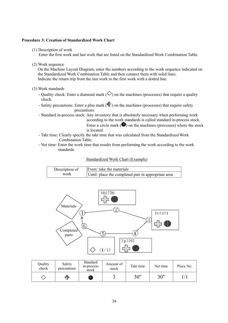
Procedure 3: Creation of Standardized Work Chart
(1) Description of work Enter the first work and last work that are listed on the Standardized Work Combination Table.
(2) Work sequence
On the Machine Layout Diagram, enter the numbers according to the work sequence indicated on the Standardized Work Combination Table and then connect them with solid lines. Indicate the return trip from the last work to the first work with a dotted line.
(3) Work standards
- Quality check: Enter a diamond mark ( ) on the machines (processes) that require a quality check.
- Safety precautions: Enter a plus mark ( ) on the machines (processes) that require safety precautions.
- Standard in-process stock: Any inventory that is absolutely necessary when performing work according to the work standards is called standard in-process stock. Enter a circle mark ( ) on the machines (processes) where the stock is located.
- Takt time: Clearly specify the takt time that was calculated from the Standardized Work Combination Table.
- Net time: Enter the work time that results from performing the work according to the work standards.
Standardized Work Chart (Example)
From: take the materials Description of
work Until: place the completed part in appropriate area
Materials
Completed parts
Quality check
Safety precautions
Standard in-process
stock Amount of
stock Takt time Net time Piece No.
3 30'' 30'' 1/1
35
3.5 Elemental Work Analysis
(1) Elemental work analysis and analytic units
Think of each individual action used to operate something as 1 unit. (The objective of an action, such as picking up or putting down a target object)
(2) Procedure for measuring time
(The observation point is the instant that the work is completed) 1. Look at the work sequence and memorize it 2. Enter work elements 3. Measure the time for 1 cycle 4. Measure the time for each elemental work 5. Combine the time for 1 cycle and the time for each elemental work 6. Measure any unmeasured elemental work 7. Measure any exceptional work
36
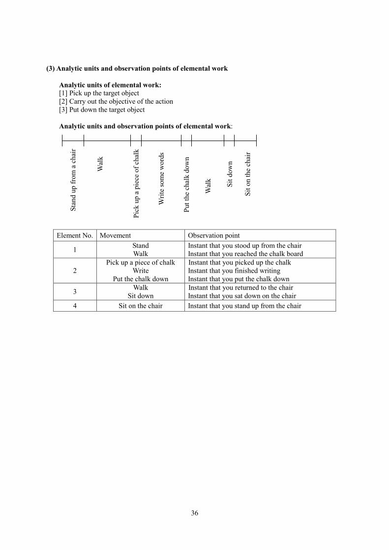
(3) Analytic units and observation points of elemental work
Analytic units of elemental work: [1] Pick up the target object [2] Carry out the objective of the action [3] Put down the target object Analytic units and observation points of elemental work:
Element No. Movement Observation point
1 Stand Walk
Instant that you stood up from the chair Instant that you reached the chalk board
2 Pick up a piece of chalk
Write Put the chalk down
Instant that you picked up the chalk Instant that you finished writing Instant that you put the chalk down
3 Walk Sit down
Instant that you returned to the chair Instant that you sat down on the chair
4 Sit on the chair Instant that you stand up from the chair
Stan
d up
from
a c
hair
Wal
k
Pick
up
a pi
ece
of c
halk
Writ
e so
me
wor
ds
Put t
he c
halk
dow
n
Wal
k
Sit d
own
Sit o
n th
e ch
air
37
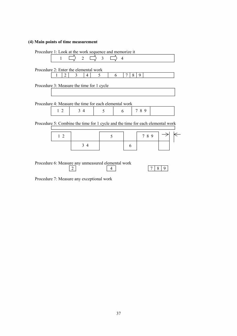
(4) Main points of time measurement
Procedure 1: Look at the work sequence and memorize it 1 2 3 4
Procedure 2: Enter the elemental work
1 2 3 4 5 6 7 8 9 Procedure 3: Measure the time for 1 cycle
Procedure 4: Measure the time for each elemental work
1 2 3 4 5 6 7 8 9
Procedure 5: Combine the time for 1 cycle and the time for each elemental work
1 2 5 7 8 9
3 4 6
Procedure 6: Measure any unmeasured elemental work
2 4 7 8 9 Procedure 7: Measure any exceptional work
38
3.6 Work Kaizen and Equipment Kaizen
Work kaizen refers to things such as, determining the work rules, reassigning the allotments, clearly specifying the arrangement and storage areas for items, and the kaizen of work movements, etc.
(1) The structure and equipment of production
The structure of production refers to the process of turning materials into completed products and includes such things as the manufacturing method and the procedures of shigoto (value-adding work), etc.
(2) Problem points of equipment kaizen
[1] Equipment kaizen is expensive [2] Equipment kaizen cannot be redone from the start [3] There is a strong possibility that equipment kaizen will fail at a genba (work site) where work
kaizen has not progressed
39
3.7 Points of Focus in Work Kaizen The starting point is discovering the needs of kaizen
“Superficial” standardization ® problems become obvious ® kaizen ® standardization
(1) Standardized work and kaizen items
[1] Reduction in number of man-hours [2] Reduction of work-in-process inventory [3] Reduction of quality defects [4] Enhancement of production capacity [5] Layout [method of combining processes] [6] Visual controls
40
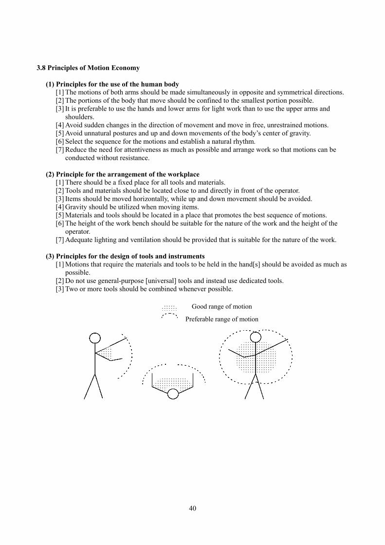
3.8 Principles of Motion Economy (1) Principles for the use of the human body
[1] The motions of both arms should be made simultaneously in opposite and symmetrical directions. [2] The portions of the body that move should be confined to the smallest portion possible. [3] It is preferable to use the hands and lower arms for light work than to use the upper arms and
shoulders. [4] Avoid sudden changes in the direction of movement and move in free, unrestrained motions. [5] Avoid unnatural postures and up and down movements of the body’s center of gravity. [6] Select the sequence for the motions and establish a natural rhythm. [7] Reduce the need for attentiveness as much as possible and arrange work so that motions can be
conducted without resistance.
(2) Principle for the arrangement of the workplace [1] There should be a fixed place for all tools and materials. [2] Tools and materials should be located close to and directly in front of the operator. [3] Items should be moved horizontally, while up and down movement should be avoided. [4] Gravity should be utilized when moving items. [5] Materials and tools should be located in a place that promotes the best sequence of motions. [6] The height of the work bench should be suitable for the nature of the work and the height of the
operator. [7] Adequate lighting and ventilation should be provided that is suitable for the nature of the work.
(3) Principles for the design of tools and instruments
[1] Motions that require the materials and tools to be held in the hand[s] should be avoided as much as possible.
[2] Do not use general-purpose [universal] tools and instead use dedicated tools. [3] Two or more tools should be combined whenever possible.
Good range of motion Preferable range of motion


![Toyota Production System[1]](https://img.pdfslide.us/doc/110x75/546c9c0db4af9f20468b470e/toyota-production-system1.jpg)