Embed Size (px)
Citation preview
>
TOYOTA . ..... ELECTRICAL WIRING: .) ..•• (.:J: ~"G tIll'"
, .
FOREWORD
This wiring diagram has been prepared to provide information on the
electrical system of the 1982 TOYOTA CeUCA SUPRA, MA61L
series.
All information in the manual is based on the latest product information
at the time of publication. However, specifications and procedures are
subject to change without notice.
@ 1981 TOYOTA MOTOR SALES CO., LTD. All rights reserved. This book may not be r.· produced or copied, in whol. or in part,. without the written permission of Toyota Motor Sales Co" Ltd.
TOYOTA MOfOR SALES CO.LTD.
INDEX
A INTRODUCTION
B TROUBLESHOOTING
1 POWER SOURCE
2 CHARGING SYSTEM
3 STARTING AND IGNITION SYSTEMS
4 STOP LIGHTS
5 BACK-UP LIGHTS
6 RADIO AND STEREO PLAYER
7 CLOCK (Analog Meter)
8 HORNS
9 SEAT BELT WARNING SYSTEM
10 REAR WINDOW DEFOGGER
11 REMOTE CONTROL MIRRORS AND CIGARETTE LIGHTER
12 FRONT WIPERS AND WASHER
13 REAR WIPER AND WASHER b
14 POWER WINDOWS AND SUN ROOF
15 OVERDRIVE
16 TRIP COMPUTER (Digital Meter)
17 DOOR LOCKS
18 FOG LIGHTS
19 RETRACTABLE HEAD LIGHTS
20 TAIL LIGHTS AND ILLUMINATION
21 TURN SIGNAL AND HAZARD WARNING LIGHTS
22 INTERIOR LIGHTS , ',.' 23 COMBINATION METER (Analog)
.'. ",.-24 COMBINATION METER (Digital)
ity ',*. .. 1<'25 CRUISE CONTROL
26 EFI SYSTEM
·f 27 AUTOMATIC AIR CONDITIONER
,;GROUND POINTS
"' G'F7'
A II\lTRODUCTION
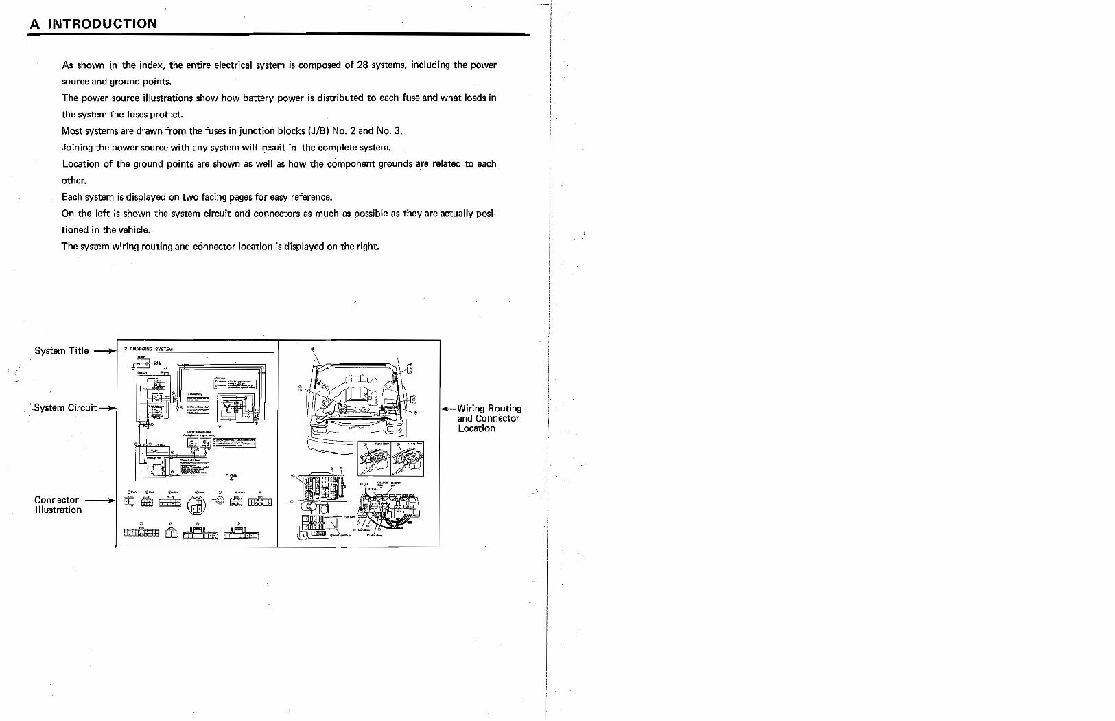
As shown in the index, the entire electrical system is composed of 28 systems, including the power
source and ground points.
The power source illustrations show how battery power is distributed to each fuse and what loads in
the system the fuses protect.
Most systems are drawn from the fuses in junction blocks (JIB) No.2 and No.3.
Joining the power source with any system will ~esuit in the complete system.
Location of the ground points are shown as well as how the cOmponent grounds'are related to each
other.
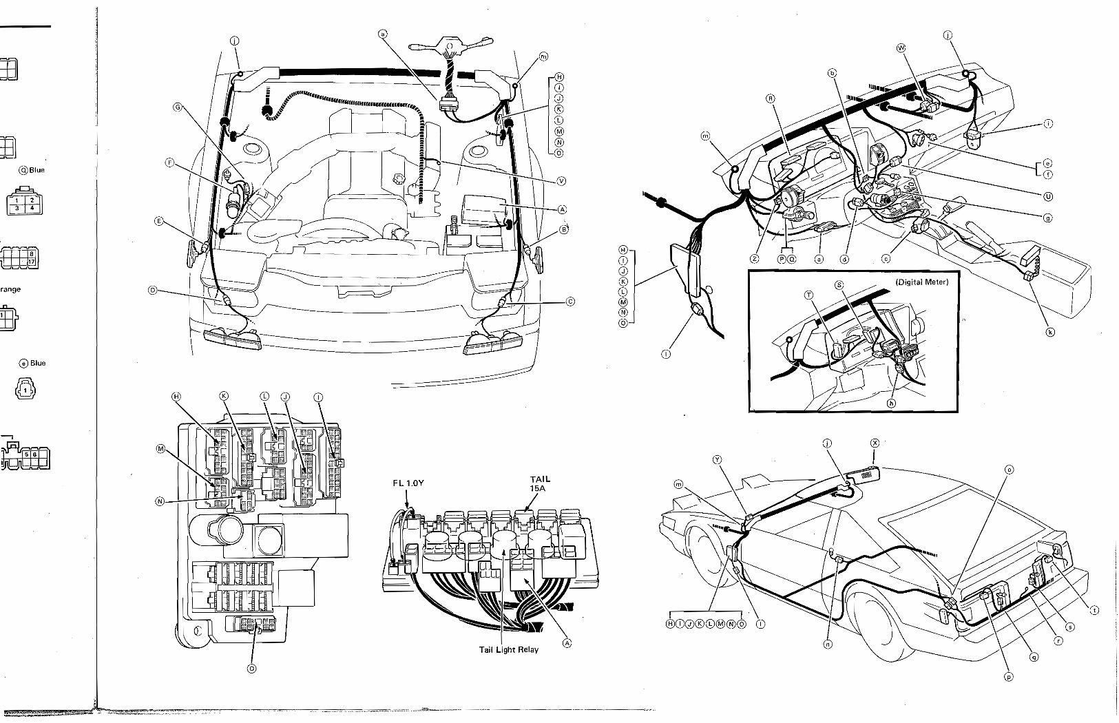
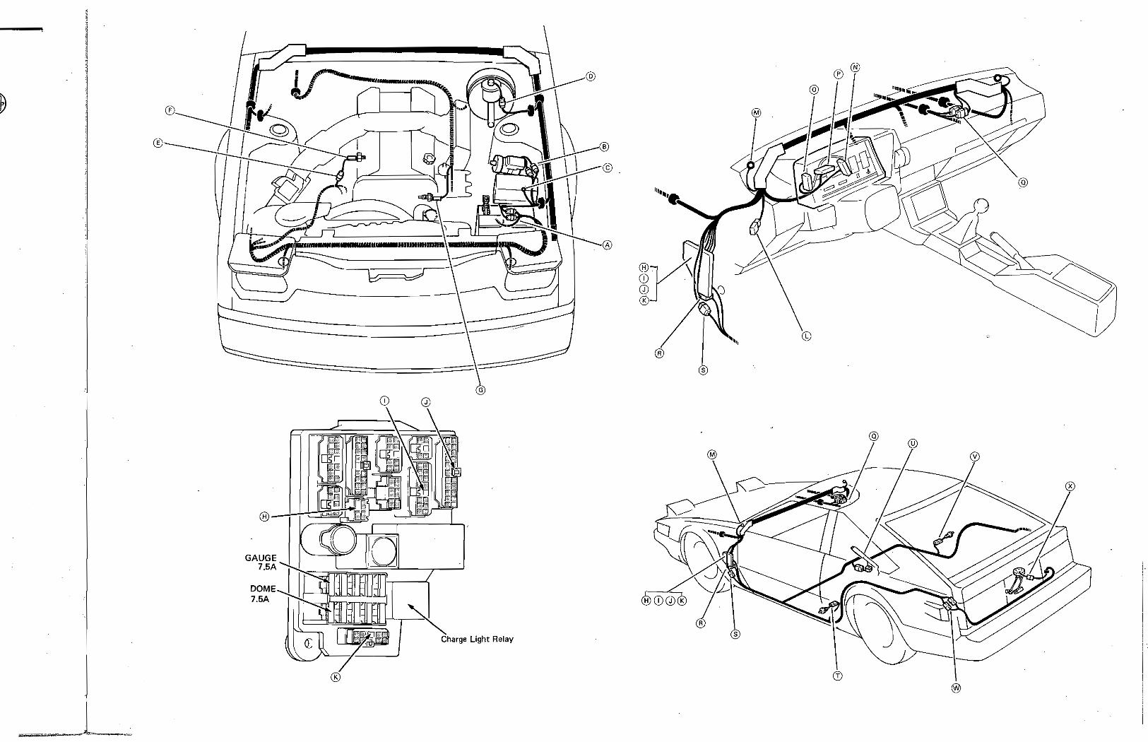
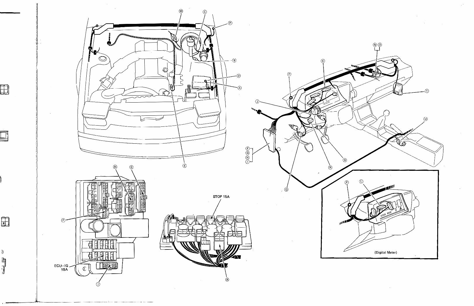
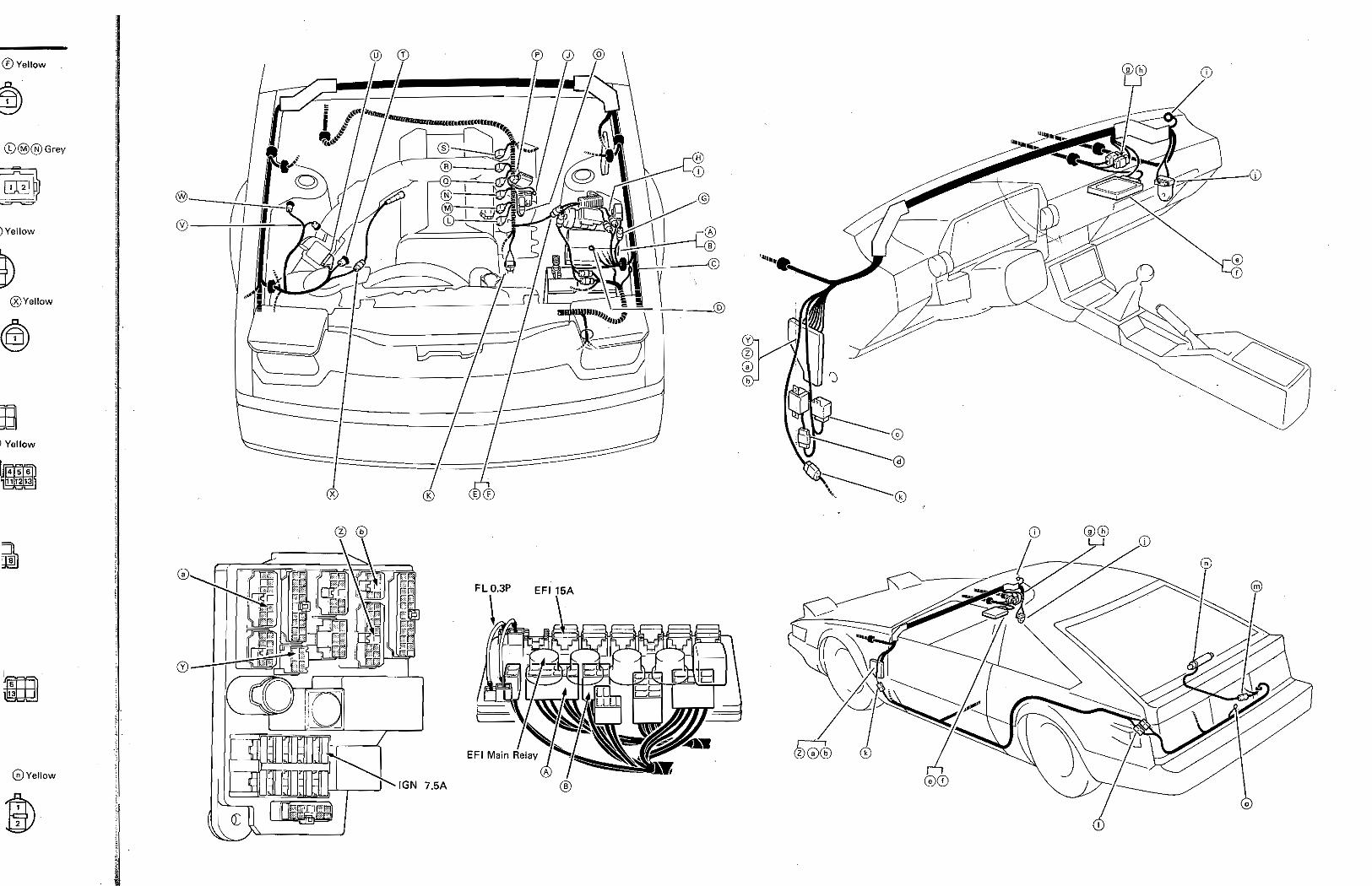
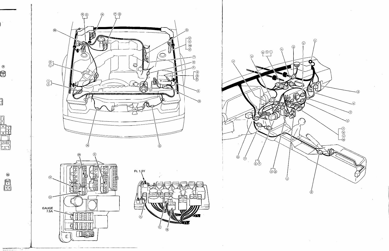
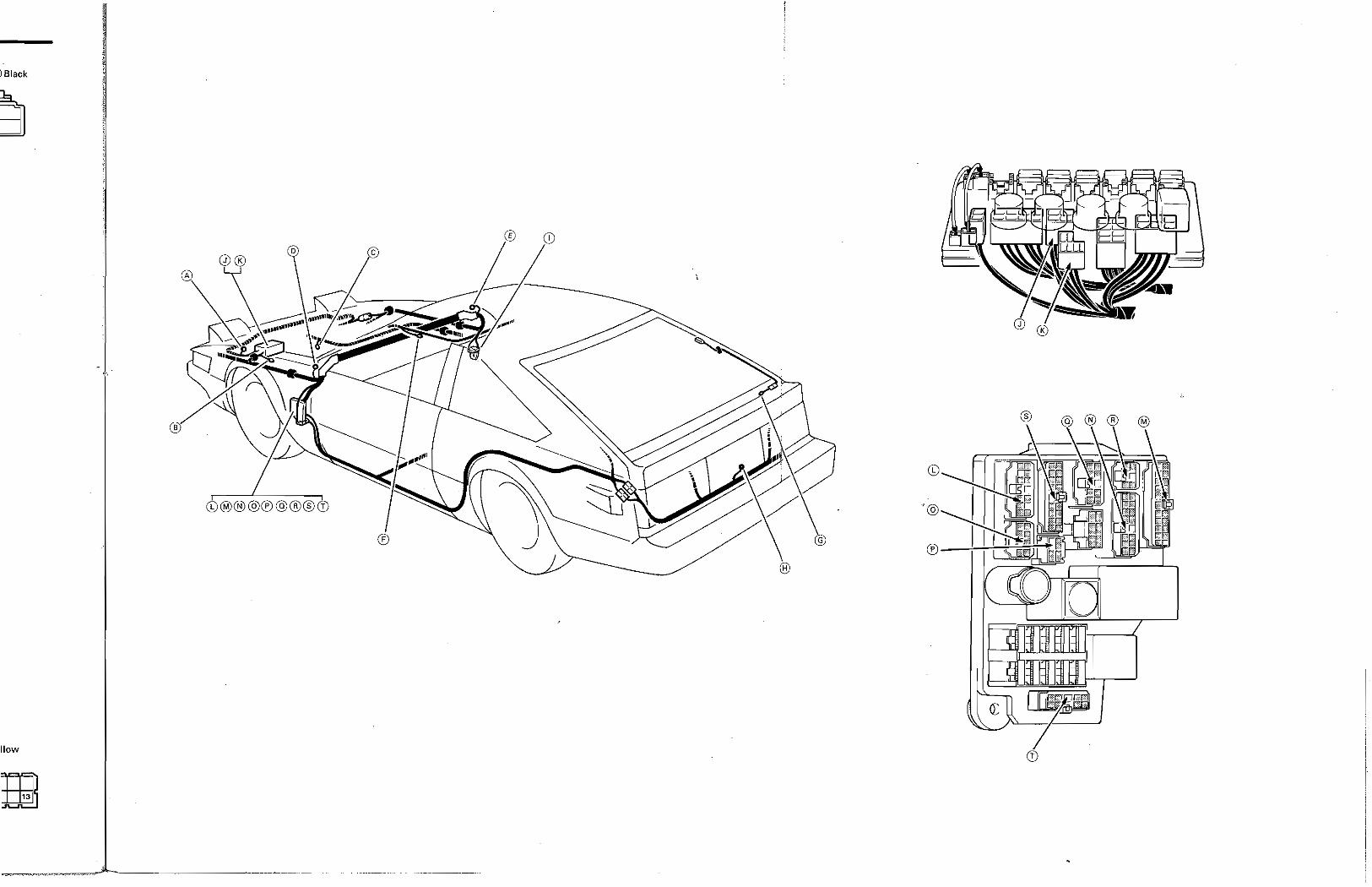
Each system is displayed on two facing pages for easy reference.
On the left is shown the system circuit and connectors as much as possible as they are actually posi
tioned in the vehicle.
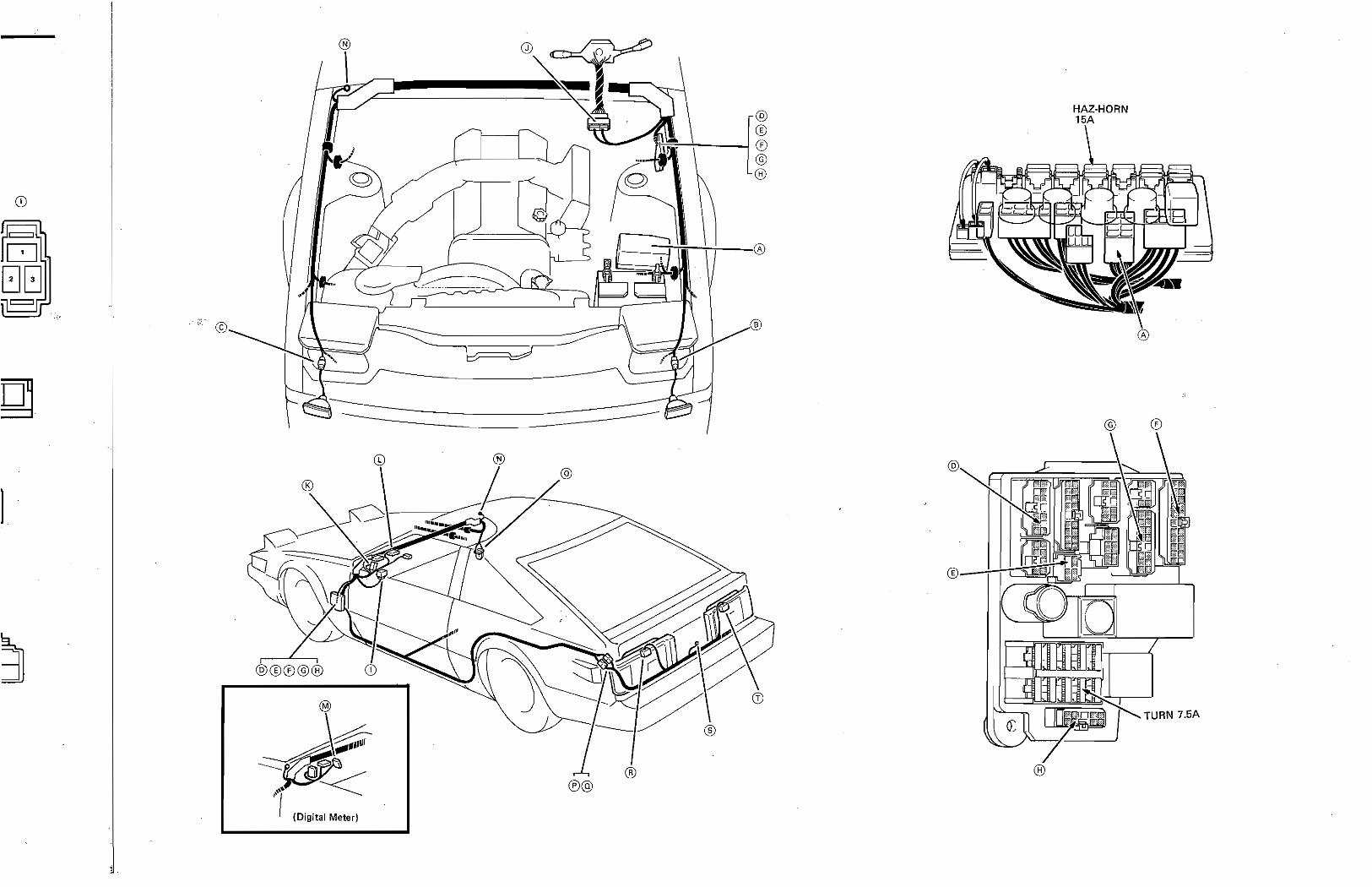
The system wiring routing and connector location is displayed on the right.
System Title
'System Circuit
Connector ----,l!Oj Illustration
o
IQI ! £}! II II
_Wiring Routing and Connector Location
INTRODUCTION
Troubleshooting Hints and Component Operation
For assistance in understanding the system and help in repair, voltage, resistance or operation of each
component can be found boxed within the system circuit.
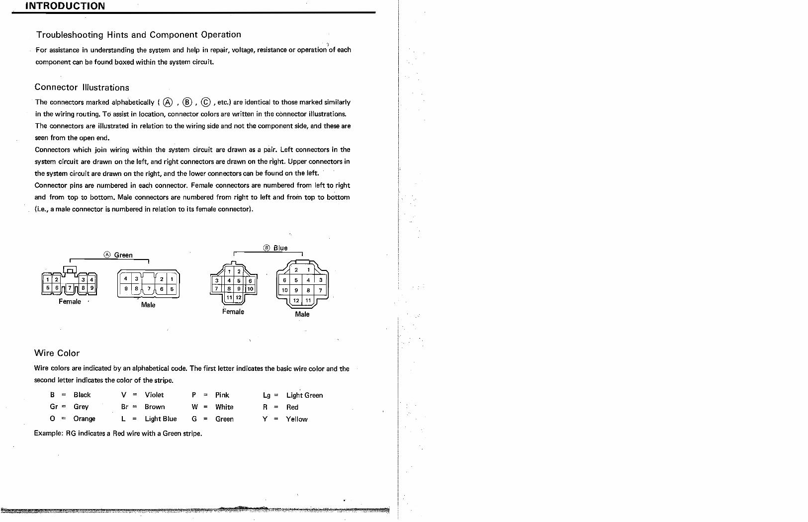
Connector Illustrations
The connectors marked alphabetically ( ® ' ® ' © ,etc.) are identical to those marked similarly
in the wiring routing. To assist in location, connector colors are written in the connector illustrations.
The connectors are illJ,Jstrated in relation to the wiring side and not the component side, and these are
seen from the open end.
Connectors which join wiring within the system circuit are drawn as a pair. Left connectors in the
system circuit are drawn on the left, and right connectors are drawn on the right. Upper connectors in
the system circuit are drawn on the right, and the lower connectors can be found on the left.
Connector pins are numbered in each connector. Female connectors are numbered from left to right
and from top to bottom. Male connectors are numbered from right to left and from top to bottom
(i.e., a male connector is numbered in relation to its female connector).
® Green ® Blue
.11..
.# 1 2 :;,... 31 4 6 6
I 7 I 8 9 10
1 11 12 -
~ 2 1 ~ 6 5 4 3
10 9 8 7
I 12 11 r 8 9 Wfu1ili 9 8 7 6 5
Female . Male Female Male
Wire Color
Wire colors are indicated by an alphabetical code. The first letter indicates the basic wire color and the
second letter indicates the color of the stripe. ,
B ; Black V = Violet P = Pink Lg; Light Green
Gr = Grey Br = Brown W = White R = Red
0 = Orange L = Light Blue G = Green Y = Yellow
Example: RG indicates a Red wire with a Green stripe.
B TROUBLESHOOTING
Troubleshooting Procedure
1. Determine what is wrong with the system.
2. First read the diagram so you understand the system. Refer to the component operation boxed
within the system circu it.
3. Locate the cause of the problem.
a. Determine whether the problem is with the common circuit (power source or ground) or
individual circuit.
Check other loads or switches which are in parallel with the problem component.
If they are normal, the problem lies within the particular system itself.
Refer to the POWER SOURCE or GROUND POINTS and check the related systems.
(NOTE: Each component is grounded at 2 or 3 points.)
If the related systems are normal, the common circuit (power source or ground points) is okay.
The problem lies within the indiVjdual system.
b. Locate the exact point of the problem by narrowing down the flrea with a voltmeter or test
lamp. ->,.,:,'/'"
4. Repair and re-check the circuit.
If any wiring was disconnected for troubleshooting, re-connect it and check the related circuits.
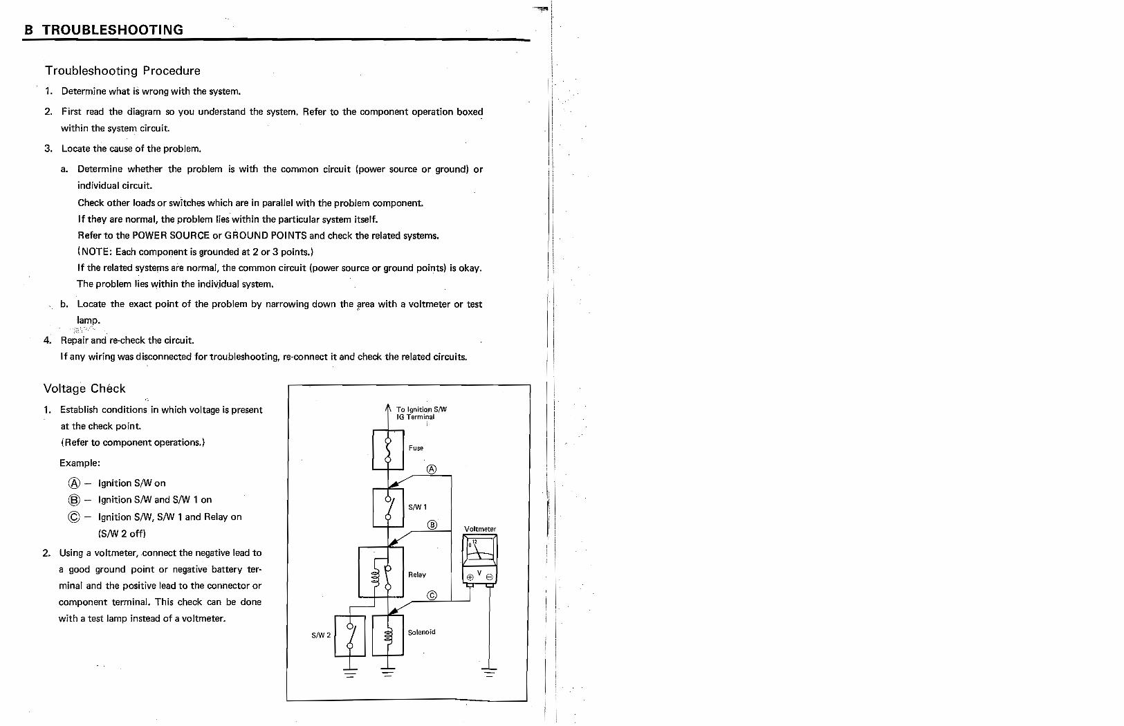
Voltage Check
1. Establish conditions in which voltage is present
at the check point.
IRefer to component operations.)
Example:
® - Ignition SIW on
® - Ignition SIW and SIW 1 on
© - IgnitionSIW, SIW 1 and Relay on
(SIW 2 off)
2. Using a voltmeter, ·connect the negative lead to
a good ground point or negative battery ter
minal and the positive lead to the connector or
component terminal. This check can be done
with a test lamp instead of a voltmeter.
To Ignitio;o 8/W IG Terminal
!
fuse
®
81W 1
®
Relay
©
~'[11 '--+-..... Solenoid
Voltmeter
0"
TROUBLESHOOTING
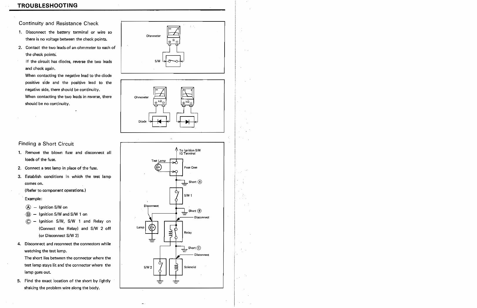
Continuity and Resistance Check
1. Disconnect the battery terminal or wire so
there is no voltage between the check points.
2. Contact the two leads{)f an ohmmeter to each of
the check points;
If the circuit has diodes, reverse the two leads
and check again.
When contacting the negative lead to the diode
positive side and the positive lead to the
negative side, there should be continuity.
When contacting the two leads in reverse, there
should be no continuity.
Finding a Short Circuit
1. Remove the blown fuse and disconnect all
loads of the fuse.
2. Connect a test lamp in place of the fuse.
3. Establish conditions in which the test lamp
comes on.
(Refer to component operations.)
. Example:
® - Ignition S/Won
@ - Ignition S/W and S/W 1 on
© - Ignition S/W, s/W 1 and Relay on
(Connect the Relay) and S/W 2 off
(or Disconnect S/W 2)
4. DiSC{)nnect and reconnect the connectors while
watching the test lamp.
The short lies between the connector where the
test lamp stays lit and the connector where the
lamp goes out .
. 5. Find the exact location of the short by lightly
shaking the problem wire along the body.
Ohmmeter
Ohmmeter
Disconnect
SIW2
4 To 19oition SIW : fG Terminal
Fuse Case
Short ®
S/W 1
Short ® ---Disconnect
Relay
Short@) -_-- Disconnect
Solenoid
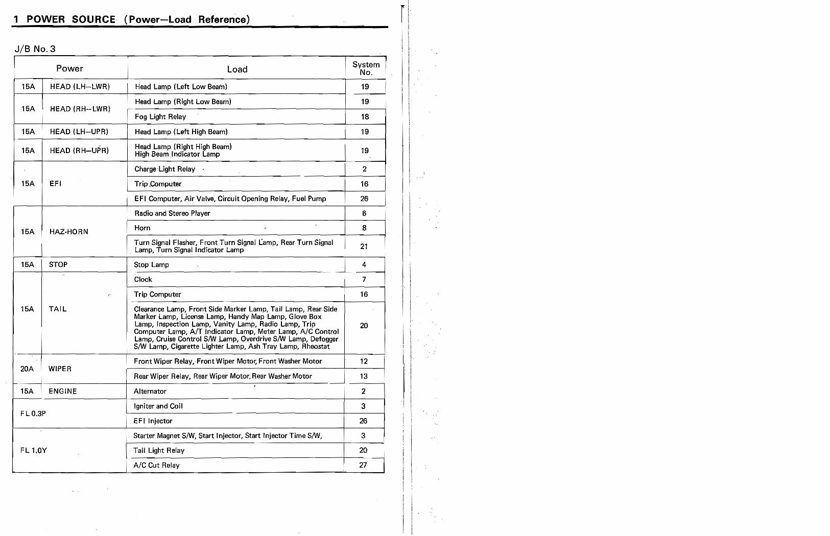
1 POWER SOLIRCE (Power-Load Reference) [ JIB No.3
I Power J Load System No.
15A HEAD (LH-LWRj Head Lamp (Left Low Beam) 19
I Head Lamp (Right Low Beam) 19
16A HEAD (RH-LWR) i Fog Light Relay 18 ,
16A HEAD lLH-UPR) I
Head Lamp (Left High Beam) 19
16A HEAD (RH-UPR) Head Lamp (Right High Beam) 19 High Beam .Indicator Lamp
Charge Light Relay 2 i ,
16A EFI Trip ,Computer .
16 !
EFI Computer, Air Valve, Circuit Opening RelaY,Fuel Pump 26 , ,
i Radio and Stereo Player 6
1M HAZ-HORN ! Horn <
J 8
, ! Turn Signal Flasher, Front Turn Signal Lamp, Rear Turn Signal i i . Lamp, Turn Signal Indicator Lamp I
21 I
I
16A STOP i Stop Lamp i 4 i Clock 7 !
" Trip Computer 16
16A TAIL Clearance Lamp, Front Side Marker Lamp, Tail Lamp, Rear Side Marker Lamp, License Lamp, Handy Map Lamp, Glove Box Lamp, Inspection Lamp, Vanity Lamp, Radio Lamp, Trip 20
i Computer Lamp, AfT Indicator Lamp, Meter Lamp, AIC Control
, Lamp, Cruise Control S/W Lamp, Overdrive S/W Lamp, Defogger I i
S/W Lamp, Cigarette Lighter Lamp, Ash Tray Lamp, Rheostat
. i Front Wiper Relay, Front Wiper Motor. Front Washer Motor 12 !
20A WIPER ! Rear Wiper Relay, Rear Wiper Motor, Rear Washer Motor !
13 _. . i ..
1M ENGINE Alternator 2 )
Igniter and Coil 3 FLO.3P
EFllnjector 26
Starter Magnet S/W, Start Injector, Start Injector Time S/W, I
3
FL 1.0Y Tail Light Relay 20
AIC Cut Relay 27
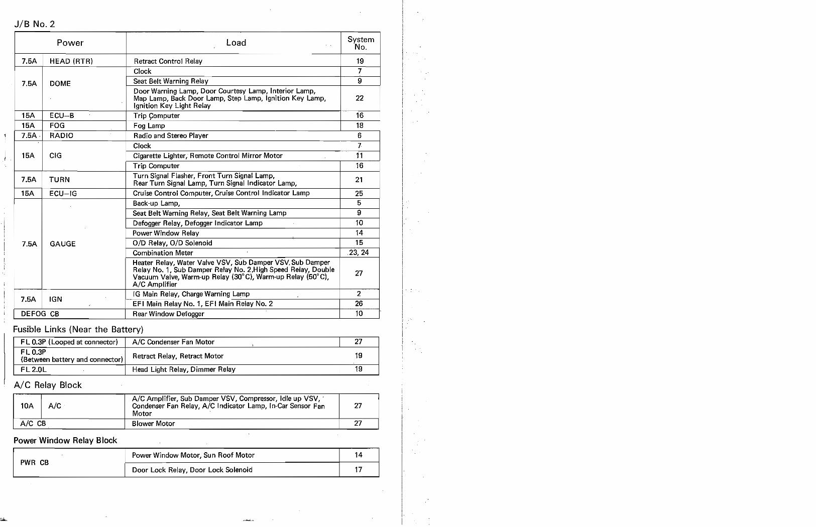
JIB No.2
Power Load System NQ.
7.5A HEAD (RTR) Retract Control Relay 19 Clock 7
7.5A DOME Seat Belt Warning Relay 9 -I Door Warning Lamp, Door Courtesy Lamp, Interior Lamp,
Map Lamp, Back Door Lamp, Step Lamp, Ignition Key Lamp, 22 Ignition Key Light Relay
, 1 CU-B Trip ~omputer 16
........................
OG Fog Lamp 18 RADIO Radio and Stereo Player 6
Clock 7 ~ ...•.....
15A CIG Cigarette Lighter, Remote Control Mirror Motor 11 .
Trip Computer 16
7.5A TURN Turn Signal Flasher, Front Turn Signal Lamp,
21 Rear Turn Signal Lamp, Turn Signal Indicator Lamp,
15A ECU-IG Cruise Control Computer, Cruise Control Indicator Lamp 25 Back-up Lamp, 5 Seat Belt Warning Relay, Seat Belt Warning Lamp 9 Defogger Relay, Defogger Indicator Lamp 10 Power Window Relay 14
7.5A GAUGE OlD Relay, OlD Solenoid 15 Combination Meter .23,24 Heater Relay, Water Valve VSV, Sub Damper VSV.Sub Damper Relay No.1, Sub Damper Relay No. 2.High Speed Relay, Double Vacuum Valve, Warm-up Relay (30G C), Warm-up Relay (50" Cl. 27
A/C Amplifier
7.5A IGN IG Main Relay, Charge Warning Lamp 2 El'l Main Relay No.1, EF I Main Relay No.2
DEFOG CB Rear Window Defogger t=1t=} Fusible Links (Near the Battery)
F L O.3P (Looped at connector) A/C Condenser Fan Motor , 27
FLO.3P ,
(Between battery and connector) Retract Relay, Retract Motor 19
FL 2.0L . Head Light Relay, Dimmer Relay 19
Ale Relay Block
A/C Amplifier, Sub Damper VSV, Compressor, Idle up VSV, lOA A/C Condenser Fan Relay, A/C Indicator Lamp, In-Car Sensor Fan 27
Motor A/C CB Blower Motor I
27
PowerWindow Relay Block
Power Window Motor, Sun Roof Motor 14 PWR CB
I Door Lock Relay, Door Lock Solenoid 17
,
r
~: i ; I
~! ',1
'I ·1, d
'Ii . \: ,
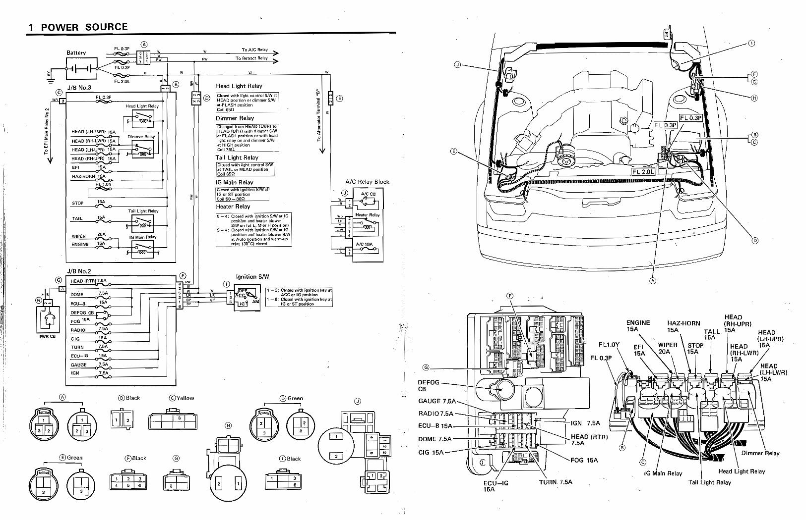
, POWER SOURCE
N 0 z ;:-.. '" 0
~ ;;:
'" {2
® FL03? w ToNCRelay ...
Battery rw w
© JIB No.3
wira FL O.3f'
HEAD !LH-lWR. 15A
HEAD (RH.LWRr1$A l HEAD (LH·UPRi 15A
3 I ~ ~ RW To Retract Relay
Head Ught Relay
c-:i-o~1 I" 'I
DImmer Relay
:vI
Head Light Relay
Closed with light contrOl 8/W at I HEAD position or dimmer srw I <It .FLASH pos.ition : ~i?"~. ___ .. , ___ ;
Dimmer Relay :changed from HEAD (LWRI to ' i HEAD {UPR) with dimmer S{W
~at FLASH position or with head light r-elay on and dimmer S/W it HIGH positiQr; ~1!2~_ .. _____ --'
,if HEAD {RH-UPR) 15A 1 Tail Light Relay
EFI ISA HAZ·HORN 15A
fL LOY
I STOI' 'SA
TAIL 1SA
WIPER 20A
ENGINE ,s):""'" l
,
Tru! Ught Relay
1-o~1 , I
10 Main Relay
1- .1
rr I
~ . CIOSl)d with Ught control SIW"I at TAl L or HEAD position Coil65H
IG Main Relay Closed with Ignition S/Wat' IG orST~ltion : COU 50 -BOil
Heater Relay ~-~c=--~
j5 - 4: Closed with ignition S/W at,lG ' I position and heater blower , S/W on {at L, M or H positionl
I
i5 4: Closed with iglJition sIW at lG po~ition and' he.ater blower $/'oV at Auto ~sition and warm-up relay (30"CJ cI¢~d
JIB No.2
@ ,.::.:.::...:.==-----------. ® Ignition SIW
!
l
[~GIf~H~E~A~D=(RT==R):7~.5~As:~~r=~~======r~fERlw~ (D ~----, ~ ::ii 2 ~I ~~~~~'~'E=il ~JLJMI~-§. '~'; ~' 3, CI""d with 'gnition "Y'::I' > • ~00M~""E_-o;.1,,5A_'>_-.... 5 I.R Ll'I 1 IACr::~ ACGcr IG position
® I., .5A ..... ~ I; r SY ~ I-. AM 1 - 6: Closoo with ignition key at N~I ~E""CU'!c-6~_<:i_:;:.:..o_--l r-;:::::I-'!-~ ..... ~ ,IG.rST"",'6oo 'l9 DEFOG CB-t _11>----'
FOG lSA "'--'iV
RADIO 1.SA
PWfl CB elG ,SA
TURN 7.5A
ECU-lG 15A
GAUGE 1.SA
taN 7.SA "'""'-'"
,
I
I
@Black ©Yellow
®Gr •• n ®Slack
@Green
®
'(DSlack
Ale Relay Block
Q) AleCB
LA
wa Ln y
LW
L NC10A ,
..
_______________ -----1 --------0 -----
F,L
DEFOG ----+4-:=.~~t~~J;;;;J CB
GAUGE 7.~r' __ '
RADIO 7.5A -Ftf~~ff:nITn~:~::~ ECU-B 7.5A
DOME 7.5A--;'~:-7"1t
CIG 15A
ECU-IG 15A
__ ' '~r'~ IRTR)
FOG 15A
TURN 7.5A
ENGINE 15A
-
HAZ-HORN 15A
\ F
G
®
\ ©
HEAD
@
HEAD (LH·UPR)
il il
II l
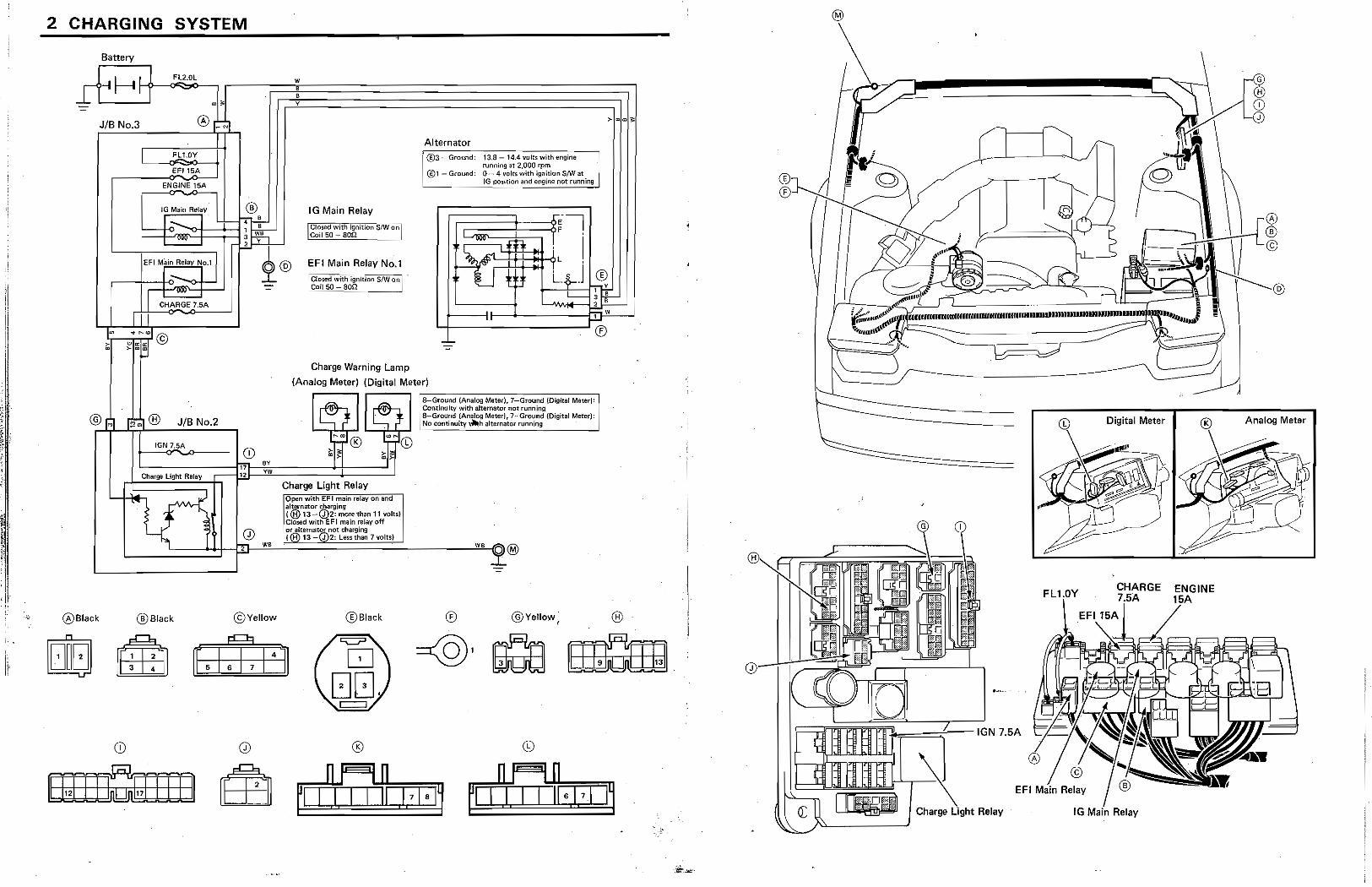
2 CHARGING SYSTEM
Battery
JIB No.3
FL1.0Y
EF'15A
ENGINE 15A
10 Main ReillY
CHAAGE7,5A
@ r~ r" ~ ® JIB No.2
IGN 7.SA
Charge light ReillY
®Black ®8lack
.,
® IG Main Relay
EFI Main Relay No.1 : Closed with ignition $,.w'Q'nl . 'Coil 50 - a~L ___ ..J
Alternator -----------.---
~ @3-Ground: 13.8 - 14A vojt~ with ~nqine funning at 2,000 r:pm i @1 - Ground: 0 - 4 volts with ignition S/W at tG position "'lid engine not runnIng
" ~--------------~®
Charge Warning Lamp
(Analog Meter) (Digital Meter)
CD BY
17 yw E.
Charge Light Relay
Ilopen with EFI main relay on and al~nator s;,Qarging (@ 13~(d)2: moTf! than 11 voltst
,CIOi»d with EFI main relay 6ft 'Of altemator nOt charging :(@13 Q)2: leu than 7voltsl w.
..
©Yellow ®Black
·l8-GfOU~d-(·AnaIOg Mew). 7-Ground jOig.ita! Mate<I<1 Continuity with ahematrJr not running a-Ground {Analog Meter}, 7--Ground {Digital Meterl: ~~ ctmtirrutty.h alternat(lt rl.lMing !
® @Yellow ,
Analog Meter
CHARGE
®
h==~-IGN 7.5A
Charge Relay
".
ii, I,
i,
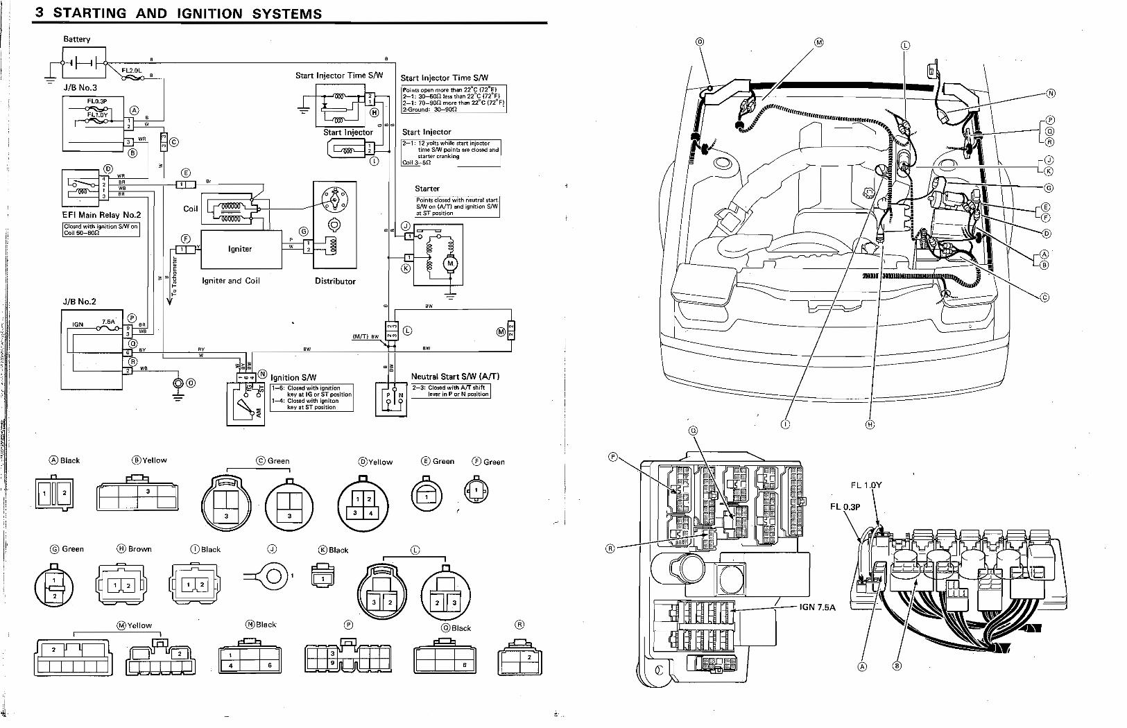
3 STARTING AND IGNITION SYSTEMS
Battery
JIB No.3
FLO.3P
FLI.OY I ® 1-;-1 , 2 W
'-----j~ '------'®
3 8R
'--_-'I--' EFI Main Relay No.2
I~~ ~9nition S/W on I
• Start Injector Time S/W
~ ~:t tID L~~~~i OO~
Start Injector
[ lj:: (D
Igniter
Igniter and Coil Distributor
Start Injector Time S/W po(ot;;l)pen more than 22"C (72 "'j 2-1: 3Q-5On less than 22"C (n"Fj 2-1: 7tl-S0f2 more than 2i"C {n"'n 2-Grotmd; 30-900 • =, ..
Start Injector r2'::':l;""l;iY·0it$-wh~il<~''''''rt'''i!\J'''· ''''e",''"'''''-'o I I tim& S!W poinb are Closed artd I $turter cranking : 'Coll3~Sn '
Starter Points dosed with neutral start~1 8m on (Am and ignltron SIW at ST posJtion
JIB No.2 • 6W
IGN 7.5A· ~.,
L 11 ___ ...."._i~~n~a~:u:_-t==='Yiy===:;l ~-------------------~~----------.... ~
(M(f)aw 9 CD
®Black
@ G"",n
r-® ~ T W6 ~ ._~.~. ® Ignition S/W
®Vellow
@Brown
@Vellow
O_@JI!:?Lt.l-6:ClOSedWith.ignitiOn, ~ 0 0 key at IG or ST position:
1Sr 1-4: CIO$ed with ignito"
key at ST position ~
©Green
(DBlaok ®Black
@Black ®
"'
@VeUow
6W
® Gr""n ®Green
@Black
FL ,~
®
..k_-""""i--1GN 7.5A
®
Ilrrtjp
! ' ! ' I
I ,
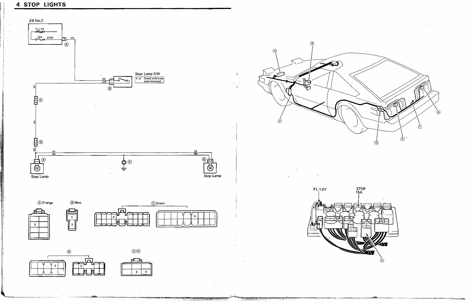
4 STOP LIGHTS
JIB No.3
fl.l.0Y
l~A STOP , ow
"--__ .-J®
r--- Stop Lamp SIW
.--___ :.:====:=::]~&:~, :IT!~~ 112
: CfOS¢dwlthbrakel' :;1 .' pedal depressed ..
®"-----I
Stop Lamp
GR W.
®Orange ®Blue
®
@Gre.n
GR
•
Stop Lamp
am:mn [II II [1111 ~ @ ®@
[0IIEl
®
. i
o
FL 1.0Y
, .
I, j
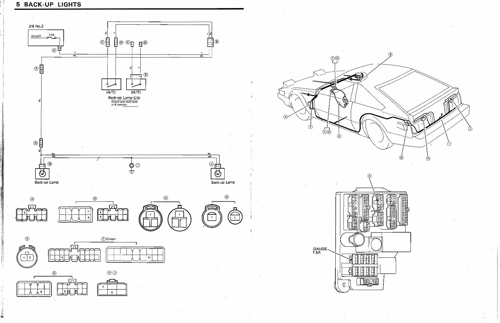
5 BACK-UP LIGHTS
JIB No.2
GAUGE ~~
y
'"
(AIT) (MIT)
Back-up Lamp SIW ICI{)Sfld with shift lawr! lin R positlUfl
y
WL
~ - . @:~~====~=====r~==========~~~J)~ ,d ®". • ~CD I t!iIJ I ~
Sack-up Lamp Back-up Lamp
® ®Green
@ mrfiIm [II lID 1 .. 11 ~ ®0
(EIIIDl '=:,Id ::::J~J
@ ®
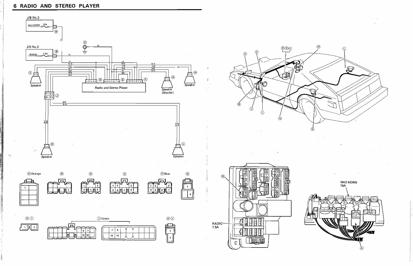
6 RADIO AND STEREO PLAYER
JIB NO.3
HAZ-HORN 15A l' ~
([)
" ,
JIB No.2 5,
7.5A ® RADIO "" ~ r-'
G,
~~y~, ~~YC ~~ fuR &B GrB VG VW V-W
CD~ g I:~ Ie:: f (~® / \ ,~lN~'@'~N~~._.'®' .. ~~N_J® -~\@ \ Speaker I I \ Speaker
Radio and Stereo Player Speaker (Woofer)
Speaker
• " ,
([)Orange ® @ ® ®Blue @
U 5, 6 7 8 ~ 4 5 6 7 fa ®CD Q)Green ®CD
®
@
®
RADIOIIi=~~ 7.5A hh;:::=~
CD
\~ ..... "
HAZ·HORN 15A
:'1
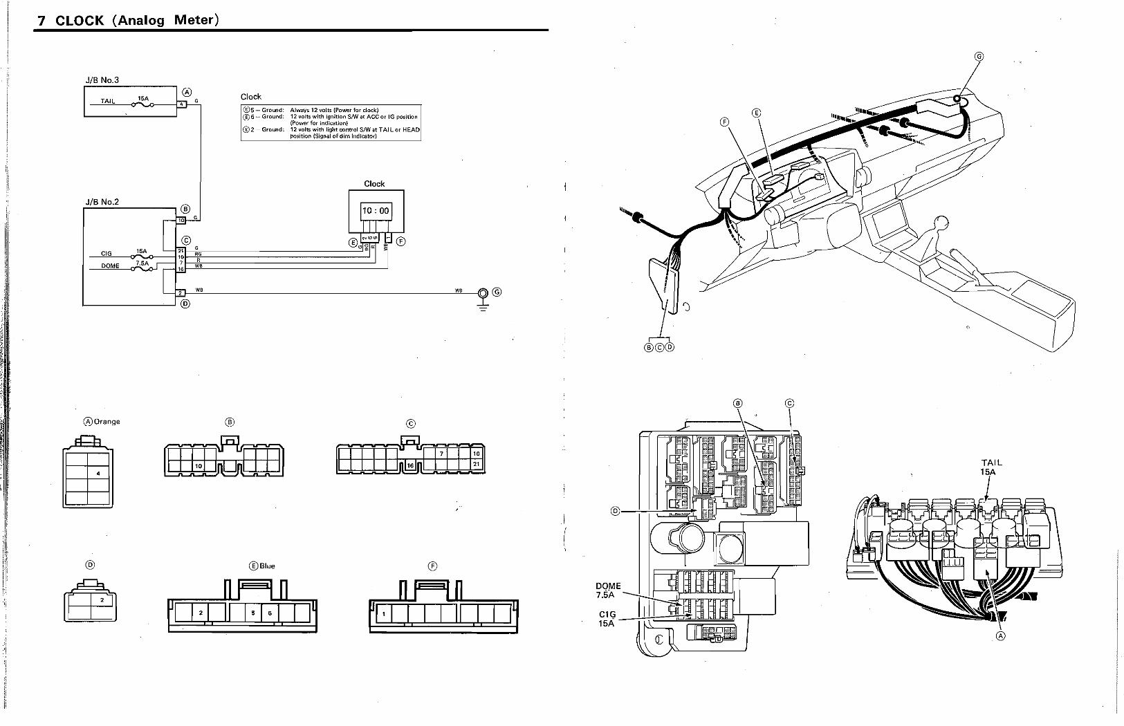
7 CLOCK (Analog Meter)
JIB No 3
o hit- G
lSA TAIL
JIB No.2 F:..c..;.;-----,® 10 G
Clock
®5 - Ground: Always 12 volts (Power for clock) ®6- Ground: 12 volts with ignition srw at ACCot IG position
(Power for indication) @2- Ground: 12 volts with light control S/W at TAIL or HEAD
position (Signal of dim indicator)
Clock
~~~2}-W~B~------------------------------------~WB~~O @ 1-----_--......1 @
00range ® ©
@ @Blue ®
I I i #
(
I~ DOME 7.5A
@
TAIL
" r
: • I
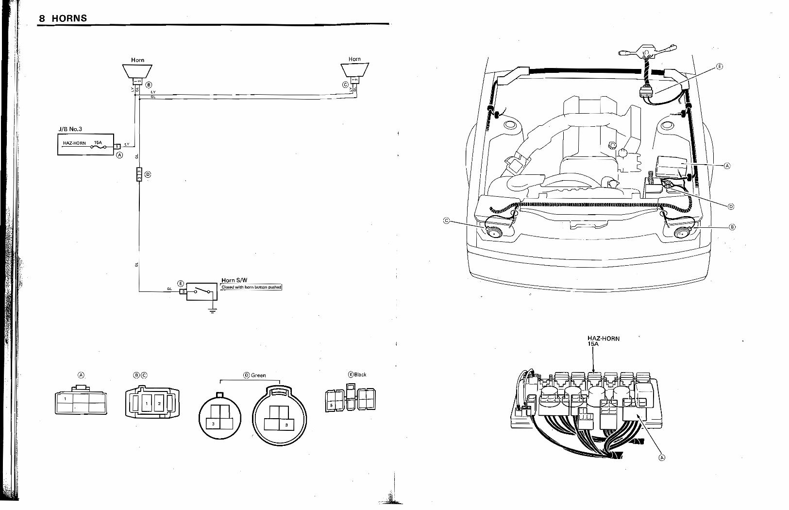
8 HORNS
JIB No.3
I HAZ·HORN O"~-'Y-' 1.... --------' ® a
® ®© -=
~, r± I I DDGD .-iT
HAZ·HORN
@Green ®Black
~
'" ,
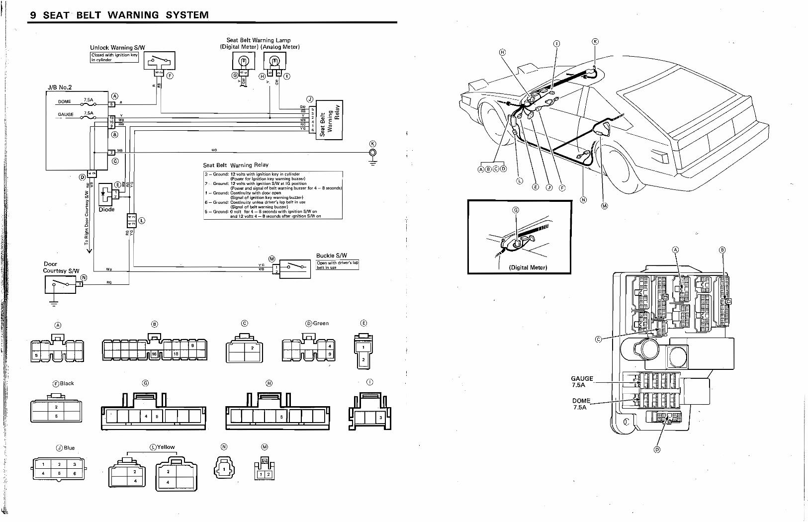
9 SEAT BELT WARNING SYSTEM
JIB No.2
DOME
Door Courtesy S/W Ip®
®
®Black
Q)Blue
Unlock Warning SIW IC""'dw"h'sn'tiOnk'YIi-I __ --""" I in cylinder . I c:.::, ~
l~®
Seat Belt Warning Lamp (Digital Meter) (Analog Meter)
~I~~~ Q)
ow -" • 3 Y ,
WB 4 6. , YO 6
>-m +'" t7I Qj: Qi .5 a: OlE ~ m me;: 81
® r--i~~~~----------------~WB~------------------------------------i!a
®
@
(i:)Yeliow
Seat Belt Warning Relay
1
:3 Ground: 12 volts with Ignition key ;(1 cylinder ··········1 {Power fm 19nitlQfl kay warning bUZHl'l ,
2 - Ground: 12 volts with ignition SIW at IG posinon : i {Power and signal of bait warning buzzer tor 4 - 8 ~eondsi: i 1 - GrQund: Continuity with door open : i {Sigrnll of ignition key warning buzzer; : 6 - Ground: ContinuitY on!e~ ddver'slap belt In use
{SigMl of bett warning oo21eri '5 - Ground: 0 volt for 4 - S second~ with ignition SNo/ on
and 12 volts 4 - B wcond$ mwr ignition S/W on
© @Green
®
~I it 1 11
®
"I
®
® @
~ ~. ~ .' I (Digital Meter)
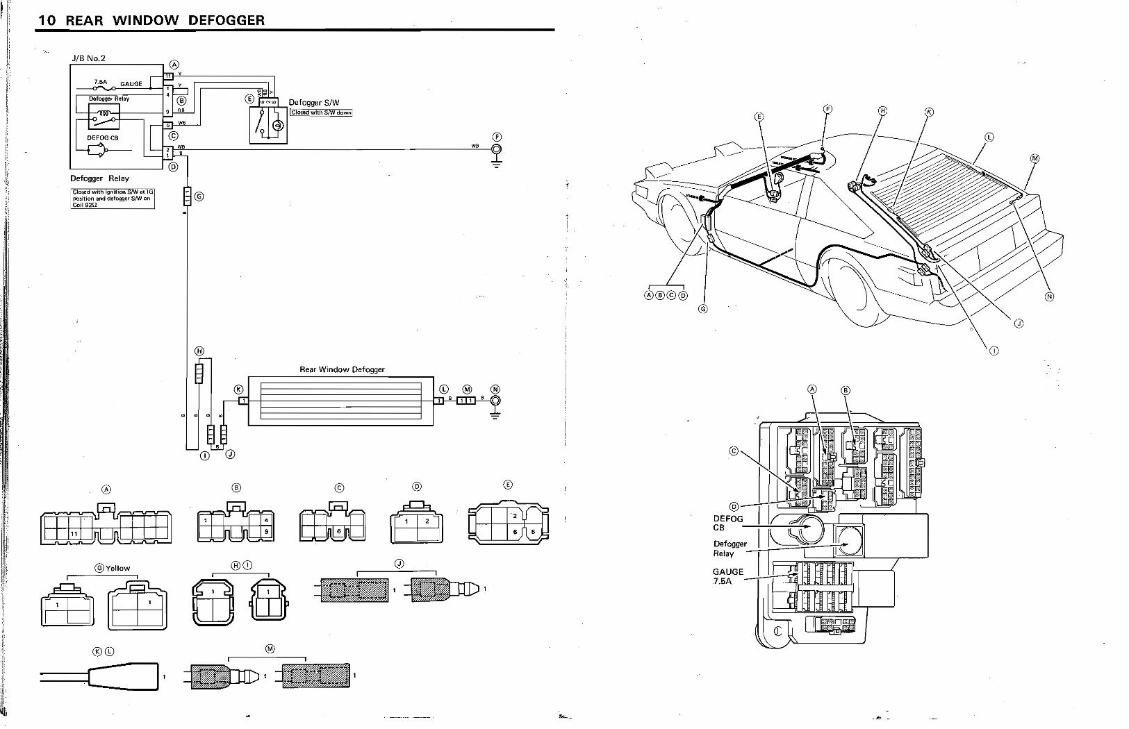
, r t 10 REAR WINDOW DEFOGGER
, '
; !
JIB No 2 r===------,@ [~b.~l1~-Y~;=======~~ ~~7§,5A~~G~AU=G=E ::1=r=1'" r!--,
I Defogger Rl:lay 4 ~® E ~il
-5CB
Defogger Relay
I C'~d _,1,.,."", ~.at IGll : positIOn ami defogger SJW on : Col! 92fl ,
@Vellow
®©
, .s
, B
® ~Nml DefoggerS/W
® ~ -
Rear Window Defogger
® © @
BQffi ®(i)
(E ®
®®©@
CD
®
? n '2
~ 6~ Defogger' ~~2:::~~~~ Relay -
GAUGE_!-.-:-+--~ 7.5A
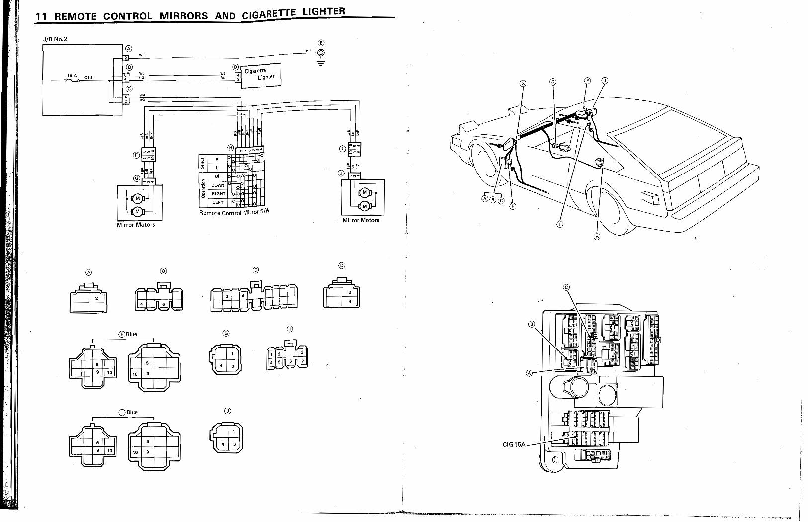
11 REMOTE CONTROL MIRRORS AND CIGARETTE LIGHTER
JIB No.2 ® ,---I:.l.J~--- __ ~_-------",,"W"j ®
I,. w,
®---.-, _--<;15~A~C"-'.'G~,J,:::fIJ:::::ilt::====:===;'''=l;;''114 Cigarette -<T RR;2. Lighter
® ~ 6' we
4 G
© ~ '"
-\'i'il , RR
r---.
..
e! UP
.2: DOWN I RIGHI
: LEFT ~ Remote Control Mirror sIW
Mirror Motors Mirror Motors
® © @
®Blue @ ®
oJ
...& l\-• i
9 101
(DBlue ._-~ ~
5 CI G 15A _...!..!.+i::::::i: 10 • ...., I •
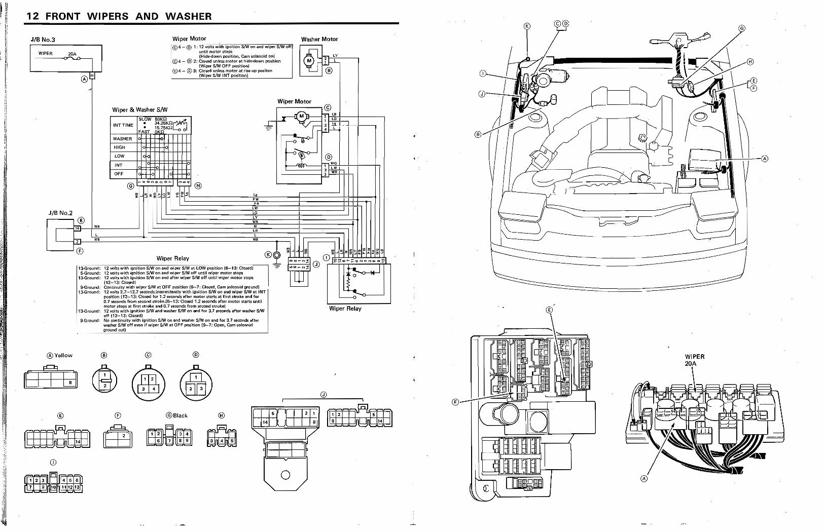
12 FRONT WI PERS AND WASHER
JIB No.3 Wi per MO.tor
WIPER 2DA
@4 @ 1: 12 ~jtswittt Ignitioo"StW on and Wipers/wOfil until motor stops tHide-down PQsition, Cam solenoid on)
JIB No.2
I ® '1'i WB
@4- @ 2: elated unwss mOlor at hide'iiown positiOn i {Wiper S/W OFF position} il
:@4- © 3: Closed unl$ts motor at riw-up poslton : (Wiper S/W INT position;
Wiper & Washer sm
INTTIME
W
HIGH
LOW
INT
SLOW • •
OFF oJ-++:
50KU d 34.25KO 15.75KD.
.......I-.--rl
.. PW P.
LW La LY WR W
CR L L
~ - -'-----'~;~~~~~~ ......... Wiper Rela
y_ ..........J®~
13-GfOUrn:i: 12 voftswith tgnith:m S/W on and wiper S/W at LOW position ($-13: Closed) -=-5-GfOUnd: 12 yoltswith ignItion SIW on and wiper S/W aff until wiper motor stops
1;I.Oround; 12 'IOltswith ignition SIW on and after wiper S/W off until wiper motor rtop!i i12-13: Closed)
9-Ground: Continuity willi wrpet SIW at OFF position {9-7: Closed. Cam sofeOQid gr¢und) lJ..Grnund: 12 volts 2.7-12.7 seoonci$jnMrmitently with ignition SfW on and wiper SIW at: INT i
13-Ground:
position (12-13; Closed for 12 seconds: after motor starts at first stroke and for : 0.1 seoonds from wcond strokej6-13: Closed 1.2 seconds: after motQr slart$ until motor stops at fint stroke and 0.7 seconds from -recoru:.l stroke) 12 volts with ignition SIW and washer 8/W on and fot 3.7 s&oonds after washer S/W off (12-13: Closed) No continuity with ignition S/W (In and washer SNV on and for 3,7 seoonds aftet" washer SNi off eVGfi if wiper S/W at OFF position (9-7: Open, Cam solenoid
~. __ ~g~,~~oo~,~m~I ______ _
@Yellow
®
= lIP'll 1 1"":2'1" 1'3'il11 ! .151611 n 7 91~ ,. 11111. "11
®
®
©
@Slack
~ ~
@
® ,.
"'-II
•
I
0
G
Washer Motor
@iL 12~1-B ¥~Y-. --,
,
2 WR .:...
Wiper Relay
WIPER
2 1
S mQm . ,. /
or:
~ I"
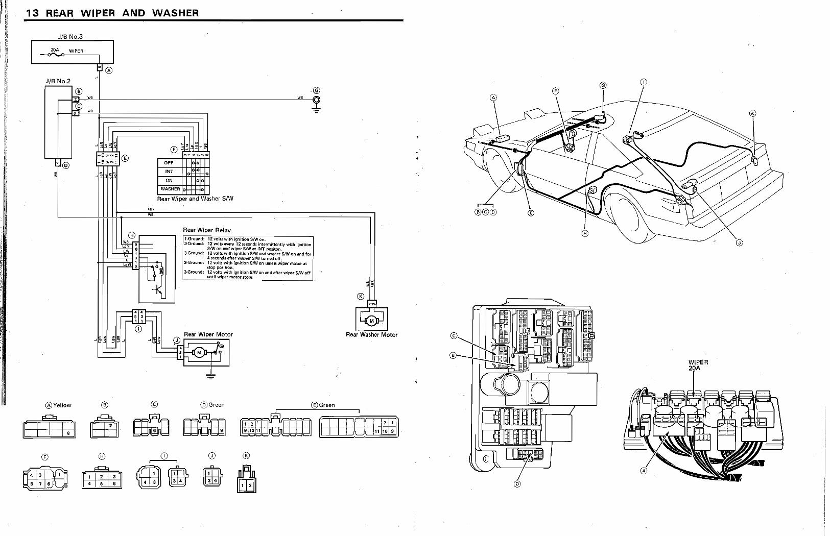
I'i 13 REAR WIPER AND WASHER j I"
rn JIB No 3 !i
20A WIPER
JIB No.2
® T we
ON
WASHER
@ w, ~
Rear Wiper and Washer SIW
WB
® .------..., Rear Wiper Relay ;"l":Ground: 12··VO·~",-W~ith~ig-n~jti-on-cs'"'tlVC"o-n-. -------, 'a.Ground: f2 volts every 12 seconds intermittently with ignition
w, ~~-LW .1-__ ,
" 3 f-L , w 2
8M on and wiper S/W lit lNT po5iton. 3·Ground! 12 volts with Ignition SNr and washer SlWon and for
4 seconds after washer 8m turned off. 2·Ground: 12 volts with Ignition S/W on unless wiper motor lit
stop position. 3eGround: 12 volts with ignition S/W Of) and after wiper S/W off
UfItfi wiper motor $tops
Rear Wiper Motor
-~~LJ0~J;t=:~=i~ ~~rr
@Yellow ® © @Green @Green
Rear Washer Motor
[ (r I.J Efj. EB:a EBcim moSmn ~-;:::::;:::=:;:f i I~I O~'11~11:1;~ ®
~ ~
®
~ ttlt!1dJ
,
,
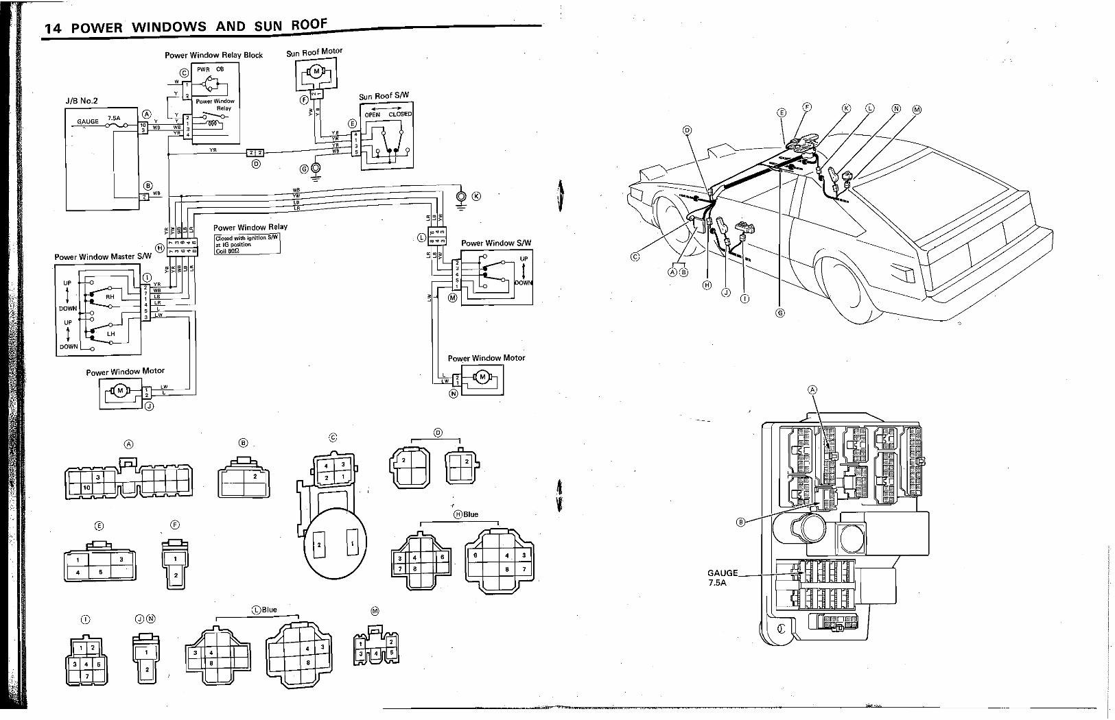
14 POWER WINDOWS AND SUN ROOF
Power Window Relay Block
PWA CB
Sun Roof Motor
JIB No.2
UP
I DOWN
UP
t DOWN
7.5A
CD 2 VR 7 WB 1 LB
--0---1' LR 5 L 3 LW
Power Window Motor
®
CD
1 2
0®
LW L
®
VR 2 2
@
Power Window Relav Closed with ignition S!W at IG position Coil BOn.
®
(l)Blue
~
'L
WB VW LB LR
1
4
8
~ 3
VB VW
©
r
Sun Roof S/w OIl ..
OPEN CLOSED
®
®
~Ir OW
Pow.er Window Motor
@ I
m m @Blue
~ .. 4CBF
~ ~
~ 6
l
~ 4 3
8 7
r
®
4 , GAUG~ ___ ~+-~H~ 7.5A :=~:~~~I

15 OVERDRIVE
JIB No.2 ,.=..:..:::::=------.0 7,5A ,r 1fI ~ GAUGE
ll.
010 Relay
1-3: ppan with ignitlon S/W on and % thermo SIW closed (CruiS(l control Maln S/W offL
'"See $Yrtem No, 25 CRUISE CONTROL whe'n Cf1Jlse control MAIN sm is : turned on.
®
OlD Thermo S/w
v.
010 Main S/W I Clo,"" with S!W pu"'''' '":Jm
®Red
0/0 Solenoid I Appro,. Ian I
@
YR 0
@ ;;;; I;;;;,
ow •
~ ~ E 8 E ~ 8
~ 0 ....
I
i
I I
7.5A
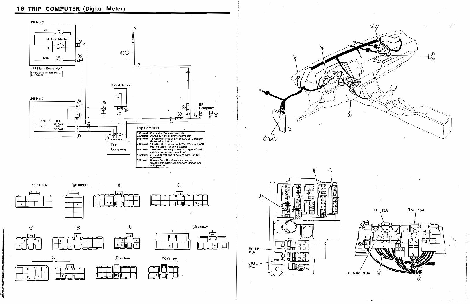
16 TRIP COMPUTER (Digital Meter)
JIB No 3
EFI 15A
EFI Main Relay No.1
....-:: I -, I '
TAIL ]!!A
EFI M,ain Relay No.1 L Closed with ignition S!W on j ~?il 5O-8Oi1 _ ..... __ .
® ",.
JIB No.2 F-'-==--------,@ @
,.;; 0 G
ECU-5 lSA
r-~U,~~,r_~~~_--4(J.
I -®
1i' e,
BY WL 'G G
Speed Sensor
L-_____ ---'® t'J1~i~~~ Ii. CDI ... ~M«...,_4" ...
®Vellow ®Orange
® ®
Q ~ ®
Trip Computer I
@
CD
1 2 !
4 5 5
CDYellow
w ,.
Trip Computer
I EFI I . Computer
CDEr ~~ ®
11-Groufld: Cont!nuity (Computet ground) I : 3-Ground: Alway, 12 volts [Power for computer) : &Ground: 12 vo!t$ with ignition 8!W lit ACe or IG po;ition : , (Power ot indication) '7·GrQund: 12 volts with light rontrot srw at TAIlor HEAD,
position (Signal for dim indication) :1
2·GrolJl'ld: 10-13 IItItts with engine running (Signal ;)f fuel I
inj8ctiOfl fur voltage oorreai<m; : 4-Ground: 9--iSvotts wIth engine running ~I of fuel
5-GrOUl\d: ~';~~rom 12 toO 'iOla 4 times. per I'
sP(lodometer shaft revolution with ignition S/W L--__ at I G po~itwn
®
Q)Veliow [ I
3
7
@Vellow
t
I ; !
J !
CIG 15A
EFI 15A TAIL 15A
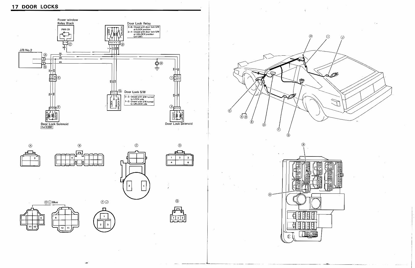
1 7 DOOR LOCKS
®
..A \.. II 6
11 12
Power window Relay Block
®
®CDBlue
~ ~ . 6
~ 12 " Ir
g(jor Lock Re.I __ .y'-,-~~ 2-6: Closed with OOor lock S!W
at LOCK position. 2-1: C1csed with door lock SIW
at UNLOcK positio(! Co!! 30n
NW<,,:;,¢ ... @
>- ~~g~
®0
Door Lock SIW
13-2: Closed with S,w't~medl
[
to LOCK sldt ' t ·,,2: Closed with SiW turned i _m. ___ to UNLOCK side i
@
01~_N
I§~ ~ ::>
Door Lock Solenoid
@
-1 2 3
4 6
@
Q I i
I
._~_.J ____ _
"
c
CD @
,
l
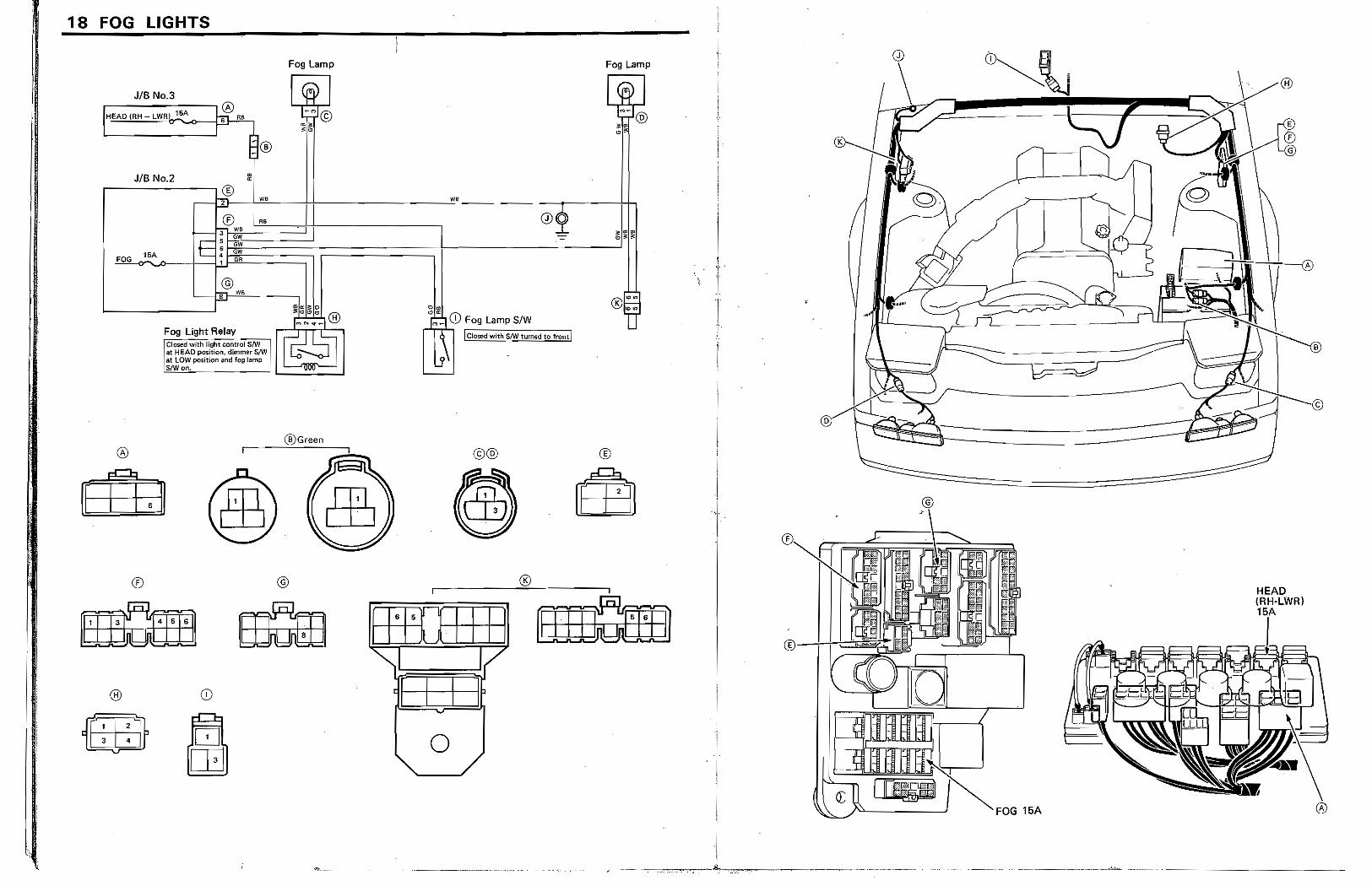
18 FOG LIGHTS
Fog Lamp Fog Lamp
JIB No.3
® . " HEAD (RH _ LWR iliA
JIB No.2
, we.
;®: I'._-"-.J-nll--·---~W' ---(])-J -r----.lij ..
! w - "'~?:: 1 .R ---------.1
r-----~®
FOG 15A
®
®
®
@ w,
Fog Ught Relay ; Closed with light control 3/W at HEAD PQSltlon. dimm8r S/'iV lit LOW position and fog lamp S/Won.
@Gr •• n
@
o •
• M<_ CD Fog Lamp S/W
! Closed with SIW turned to front I
©@ ®
[ 1"15
0 I I 11 ~I 7
t I I 1
0
®
® .. ~.
FOG 15A
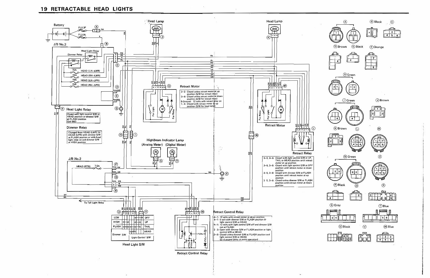
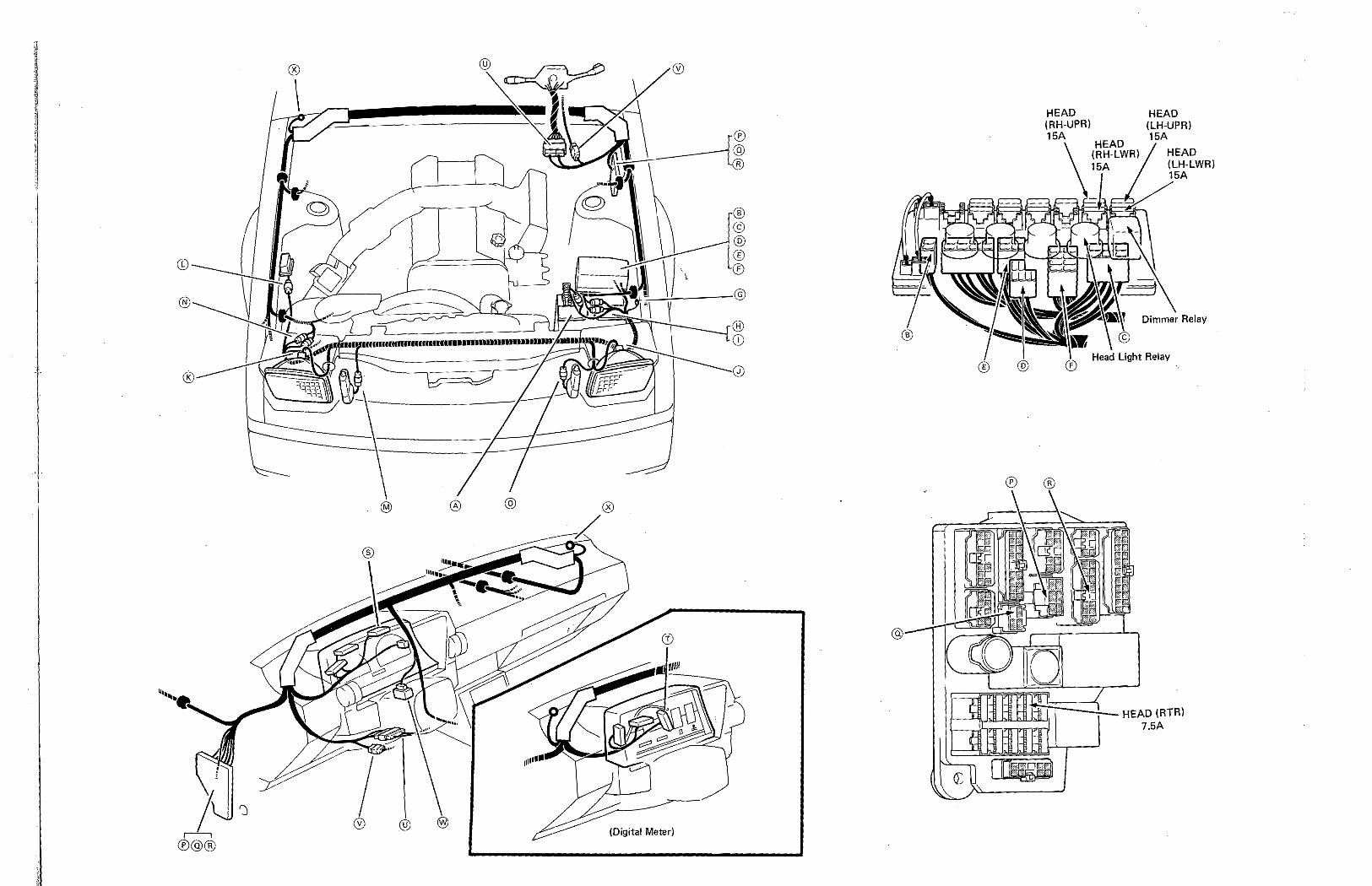
19 RETRACTABLE HEAD LIGHTS
Battery fl:,.O.3P ® ~, RW J (-f f----i ~ k::'-,:F,.:;::L-:->Q.OL __ !...1...-'-"
_® JIB No.3
Head light Relay
Dimmer Relay
rk> :..:6
...... '" 15A HEAD (RH-LWR)
,--- , r- ' 4
:-©
t-_-<,.1:,5,-A..o-~H"EA=D"!c::L:.:H-=-lJ,,P:.:R,,) ___ : I 15A HeAD (RH-UPRj @
D
r'" ® Head light Relay ,Closed with light control SAVat
Ii: HEAD position or dimnYi!( SIW at FLASH positiotl Coil65Q
Dimmer Relay
4 we
" R RL
. Head Lamp
" RC RW we 1
R ... GB: G
GR' GWi
I Retract Motor i \ 3-2: ClOsed tJnle~s letr8ct motoriat up
position (Sm for retract re~ayl 3-6; Closed unle~$ retract motodat down
pO$ition (S/W for retr<).(:i: relay) s-.Ground: 12 \!otts with retract ;elay 0r'I 1-.4: closed with retract motor up
position {SIW fOf hitotd Jam j
Head Lamp
Retract Motor ~i;;!.:1~~ N,;II) 't \11'-(')
I;;:;:;@ Changed ff()m HEAD {LWR) to HEAD (UPR) with dimme( 8/W at FLASH posItion or with head light relay on and dimmer S!W at HIGH pos(tl¢n
®~ ~CD ~ IE ~
HighBeam Indicator Lamp (Analog Meter) (Digital Meter)
INM I(
I R'
"
r--
I~ JIB No.2
® i
HEAD (RTR) 7.5A m4 RW l_======::::t====-,---~~"""'-O"--J:!J-""--J
@
t:::L~~~W~'::~::~=============~l '-________ +---1. w 14 we
L-______ ~~
"," To Tall light Relay
@ ® LOW OFF
HIGH
FLASH TAil
Dimmer SNoI I HEAD
light Control S/W
Head Light S/w
, I ~ "[rrM
Retract Control Relay
ow OR
etract Control Relay
Retract Relav
]3-5.3-6: Cklsed with light control SM at UP,
, TAIL or HEAD position until retract motor at up position
, 3-5, 3-6: Closed with fight control SJW at OFF , position until r.etract motor at down : pOsition i 3--5 J"-6: Closed with dimmer S/W at FLASH I
l:]' pcwition until retract motot at up !
position 3~5, 3-6: Cloted f,)nless dimmer S{W at FLASH
position until retract motor at d(IWn ~ition i
ttl i~ 12 volts with retract motor,(lt dO~'IIn PO~I~lonw_ .4-1: 0 volt with dimmer S{W at FLASH posltlon or
: ' light control SNJ at HEAD ; 14-1: 12 volts with light cootrol S/W off and dimmer S/W :~ not at FLASH I ~3: Open with dimmer SM at FLASH position or-light : contro! S/W at HEAD : ~-3: Closed un!e~ dirnmu SIW at FLASH position ani : light control SI\V at HEAO :t--- (2-"-4 second delay at point operation; .
[
@ I
~~ @Brown ®Black
®Green I
®® CD Green
@Brown
@Black
00 ®Orange
GDSrown
a~ e~
@Green @
@@@) ®Slack @ ®
• B3 @Grey
..JlC::jn WW!;'l""II :;=;1 IMI"illIJ @Black
(!lBlu •
® @Blue
~ ltttjjjj
I
I 1
I ! \
I I
®
®
(Digital Meter)
(~ CD
HEAD (RH-UPR) 15A
HEAD (LH-UPR) 15A
HEAD (LH-LWR) 15A
Light Relay
HEAD (RTRI 7.SA
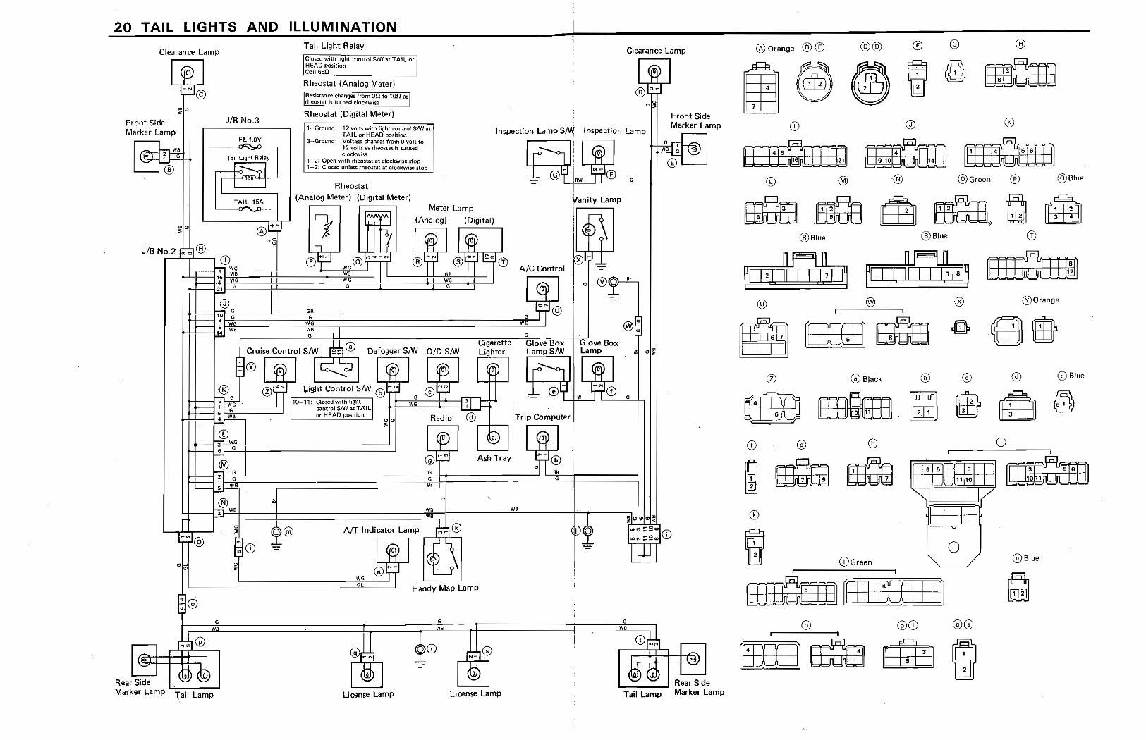
20 TAIL LIGHTS AND ILLUMINATION
Clearance Lamp
Front Side Marker Lamp r--
ws
JIB No.3
Fll.0Y
Tail Light Relay I __ ::::?
TAIL 15A
'-'I
JIB No.2 MOO ® CD 7 WG +++--1,6 we.
~_4 G ~ ___ 6
1-°6 ,. 6
..-- 4 WG
1~ wa
i i
~'" I -I """' '
Rear~
6
WB
Marker Lamp Tail Lamp
Tail Light Relay Clearance Lamp Oosed with light "oo"nirol SNJ at TAl L I
HEAD position or : Coll6Srt ...... ~ ............. -'
Rheostat (Analog Meter)
Resirtmloe changes from,O,Q to lon asl rheomt is turned C<Ockwise_~ Rheostat (Digital Meter) '"
1 Ground: 12 "Ohi with light control SNJ at TAIL 01' HEAD PQsitirm
J-..Ground: Voltage t:~1 from 0 volt to 12 vol15 as rheostat is turned ckx:kwite
Inspection Lamp stW Inspection lamp
1~2; Open with rheostat at clockwise stop 1-2: CIOlilld unleu rheostat at clockwisesrop
Rheostat (Analog Meter) (Digital Meter)
I I 1'0 I i I I G 1
6R G ' 1#G ........ ;
I ro-- Ii ~ 1 -:::::-@ ~ll\W 'TlL~®=--F --"..o---!
¥anity Lamp
~ iil~\ x ~J __
AIC Control -:: ~
~ ~l: ,. ®~. G ~
Glove Box LampSIW
r"- '-0
Glove Box Lamp
Trip Computer
Ash Tray
o
"
'" w,
AfT Indicator Lamp
GL Handy Map Lamp
6 s WD
G)~ , !
® ~
License Lamp License Lamp Tail Lamp
Front Side Marker Lamp
.---o ,
.--~
-Rear Side Marker Lamp
(j:;Orange ®® ©®
~~ ~ ~
@Blue
@
~~ ~, , ........ J
! 11 6 II
@Black
® @ ®
~ ®
~ [] []II]
@Green ® @Blue
@Blue
@ (i') Orange
C0 @Blue
~~.~m I
RTDI1I,:llli ~
o CD Green GBlu.
~ 11150 I i I ~
0G) @@
[WJJJ] rnam @ 8
131 @Blue
[±E3J
range
(V Blue
1 j j ,
1 "
1 1
®
'~----------@
(Digital Meter)
® I
®CD0®©@@@ CD
p
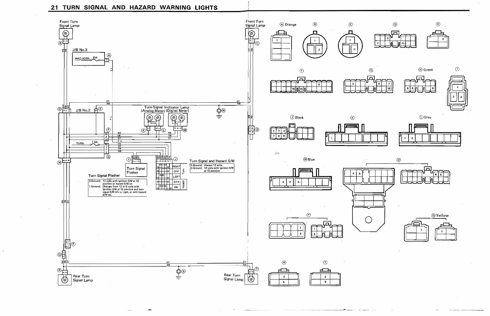
21 TURN SIGNAL AND HAZARD WARNING I,.IGHTS
Front Turn Signal Lamp
~ @-~
~,:'ii JIB No.3
® HAZ-HORN 1SA ~.
2 a ~ WlI
~~--------~@ ®L~~~
@
® \ON
Turn Signal Flasher
Tum Signal Flasher
3-Ground: 12 volts with ignition 81W at IG position or haztWd 8/W O!'l
1-Ground: Changes from 12 tQ 0 volts with ighition slW at 113 pOSition and tum signal-S/W left or right, Of' with hazard S/Wtm,
H I Rear Turn ~ Signal Lamp
,;(8I~?;>=~ 0 ,.. ~ go l'.Q N.... Tum Signal and Hazard SM
~1truR~"'GH~"T 'F"GrOuod: Always 12 volts. .1 c 2-Ground: 12 volts with ignition SIW: OFF :i at lG position :
I-
Q LEFT
GY we
OFF 1 ON ~
I Front Turn Signal Lamp
Y.y i VIS!
I ;;-;;,Q) Rear Turn IH Signal Lamp '@
® Orange ®
®
Q) Black
~rLm ~lblJdJ
@Illue
®
8
©
@
®
f 18
15
0 I ~I
I
0
@ ®
®Green
(DGrey
nl In fl r G,I. 1 Ir 1 ,I, I 11
@
III /
@Yellow
~~~-.---.----
CD
©
CD 1
@
~ l" ~
I I (Digital Meter) .
®@
@
®
-. ,~ CD
@
g ®
®
HAZ·HORN 15A
@
TURN 7.5A
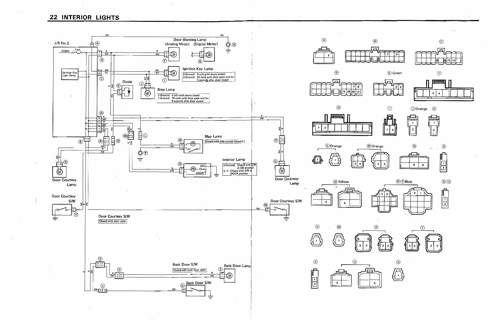
22 INTERIOR LIGHTS
JIB No.2
Door Courtesy Lamp
Door Courtesy 8/W
®
.~~ .... ___________ ---:=---:-:-:--:--;-____ -"w,-, -,
Door Warning Lamp
®
14 'tiS 13 ItY
©
@ ~ •
HW IS R 17
AW '6 7 • 0
14 RW ~
:@ AU
~
!'"
(Analog Meterl (Digital Meterl
® ~ Ignition Key Lamp
i2·Ground: Ovoltwithdoorsclosed a '2·Ground: 12 volts with door open and for
5 Mlconds after door d<!~d
C7'·""Grou--O.d~' O~,,-C"t~wIC:",'7do-o~ <i;;~"d~H2>round: 12 volts with door open and for
5 WCOM$ after door closed
Map Lamp @ r-----, [floscd with S/W tI.Irne~
~==========~~~'==C;~ )
00 I nterior lamp ,2·Grol,lnd: Closedwitn
b at ON !)OSitl n 2-1: Closed wHh S!W a
DOO_~ position
R AlV
@J
Door Courtesy Lamp
Door Courtesy S/W
'--____________ .. ____M. _____________ ----------+-2RW"'---lJ!..l--o
Door Courtesy S/W t CI()$ed with door open:
j
I I
I Back Door 8/W Back Door Lampl
~~mo==================~' c~'m~'~d'~Vi~th~b.~·Ck~ ... ~~o~o,~oP~'"~·::::]:wlc~®Uz[jJ~ •
@ frN 3 :::
® ® ©
@ ® Green ®
I I 1('
@ CD GDOrange ®
~ , I ~
(i)Orange @lOrangc @ @ i I j
G@)mmEEE~ @Yellow ®@ ,
..n. 1 2 ~ ~ 2 1 f.-.. "-
II II
'I J
I I I
@
®
®®©@I!'J
(Digital Meter)
®
DOME _-!-,,*-.-1!l. 7.5A
@
®
Ignition Key LIght Relay
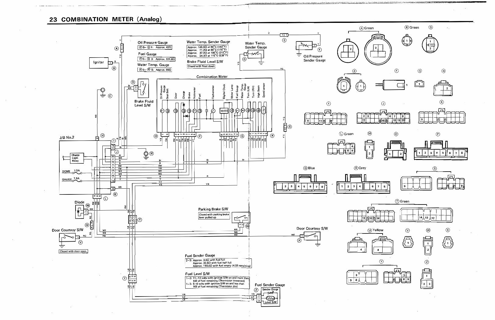
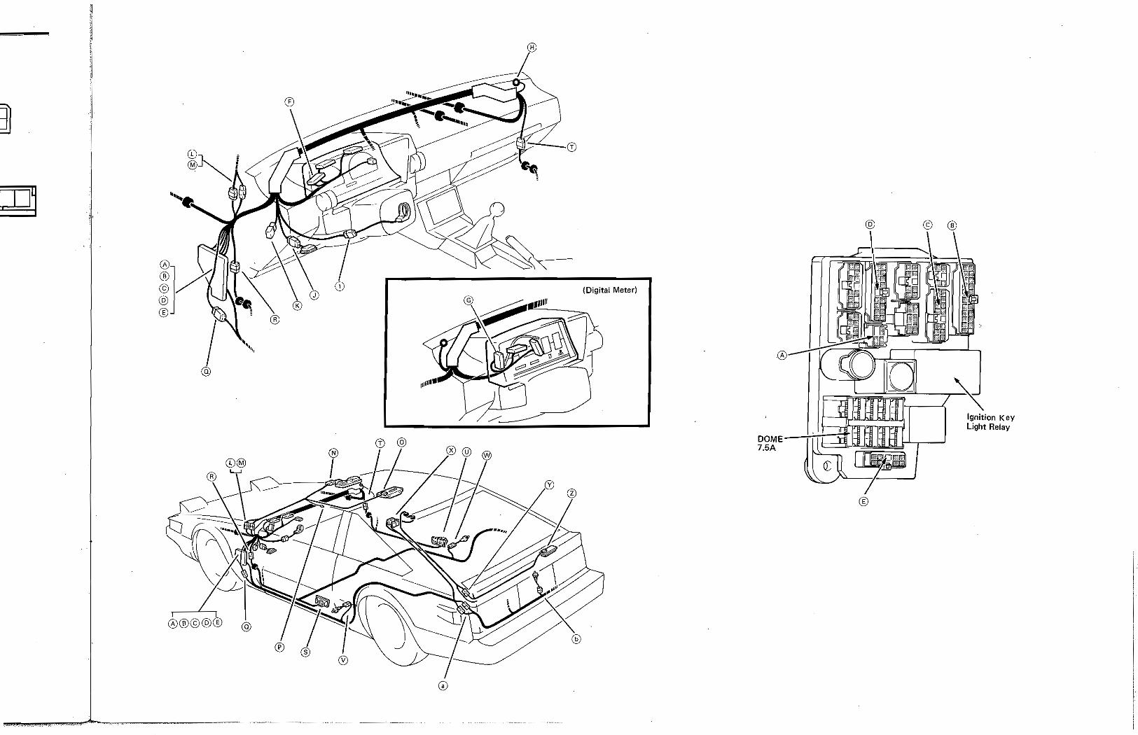
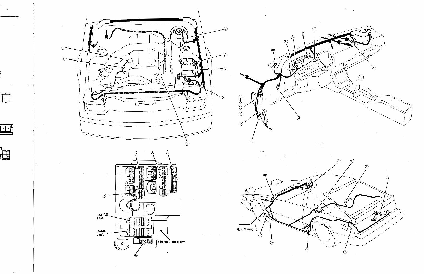
23 COMBINATION METER (Analog)
I Igniter
rire' - =
ws
Oil Pressure Gauge I ®5-@1: APprox.4201
Fuel Gauge I ®5 @ 3; APPro",.lOl.9fl!
Water Temp. Gauge r®5=n® S: Approx.'.9Ofl: ... ___ ':.:::J
r--
@n,/ s' j- Ie we ' .2.lj
L
Brake Fluid Level SIW
" YW WA WS R Y LY YA
Water T cmp. Sender Gauge Approx, 146.tm at 60 C (140 Fl 'I' ApprOlc 71.2ll at ao"c (17SoH I
ApPl'ox. 37.2ll at l00"'C (21T"F)' ~p'prox. 24:~~~_~:C i239"F)j
Water Temp.
Brake Fluid Level S/w rCTO$ed with float duwnl
,ti' Combination Meter
e " if g, 0.8. Ii 0 £0_ z
" • il ~o ~ ~ • E ... <:i !!'
.l1 g 0 " Ii
" € E • " ~ il .;; " ..
6 t! ." iii 0 0 0
'" ~ " ~ " I- ....
~ ili ~ tk ~ T..,-' ~V 1
r II. L-
-rl
~ i
I
a, a
YR
Fuel Sender Gauge
Fuel Level SIW i 1 3: 11-12 volts with ignition SIW on lind more fullnl'
T 10Q of fuel ~em~in!n.g (Thermistor immersed) 1-3. 5-6 volts with Igmtloll SIW 01'1 and less than 1
E Ii c
m • m ~ '\l ~ • 'i' c
w
y y
® y
® - Oil Pressure
Sender Gauge
YO
CD
i
@Blue
II I-I: ~ J;7;1~1 '11
L---.:,,,,,Ol',,,o! .. !Uel remain~ (l't'lCr~i$tor dry) : Fuel Sender Gauge
~li=======±u====,="~=_=,,,~~l~1
@Green @Green @
@ ® ® @ ®
@o =9 01 ' rQ) 83 ®
2 3 6 1 • 12 18 1920
o Green @
®Grey ®
(i)Green
@Yellow @ @J ® ,
lEBlW (0) ~ (0) @ @
i
r.i:HE ~ fa ~
m
1 j
®
DOME --t-m;~ 7.SA
Relay
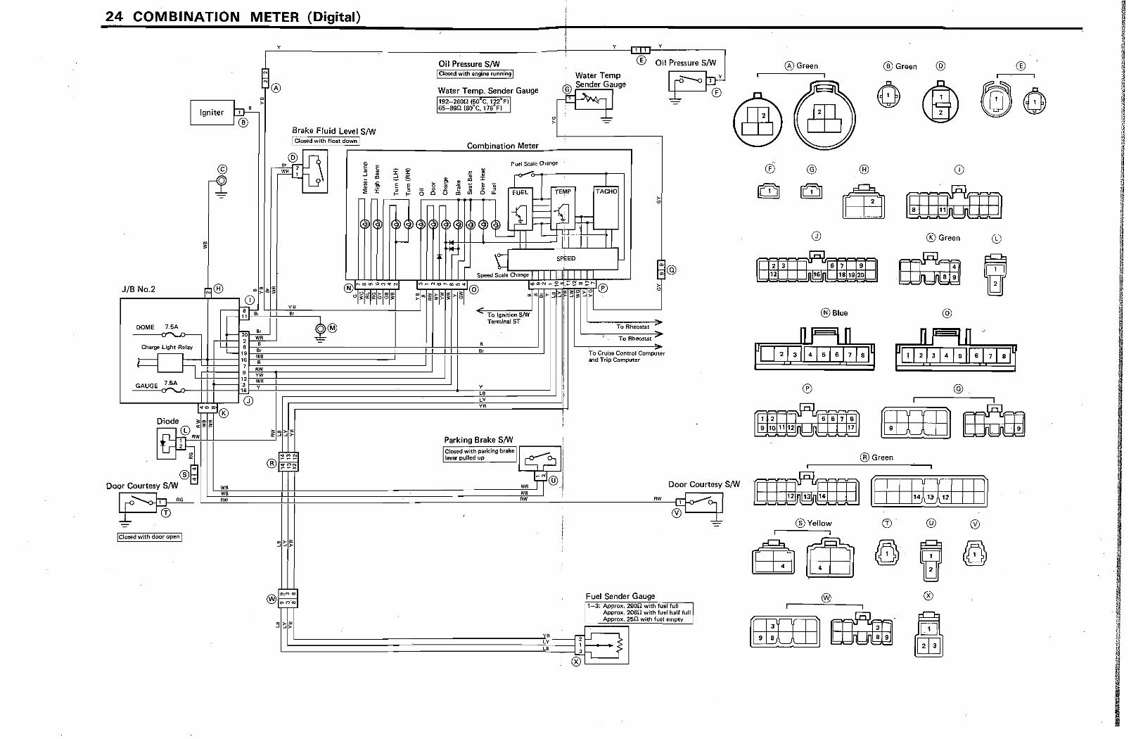
24 COMBINATION METER (Digital)
Y
, o
"
I Igniter ~> Brake Fluid Level S/W
©
1
JIB No.2 0" >
CD s} 11 8r
r'"' DOME 7.5A
Charge Light Relay
" 20 WR = 2 B 6
B. - 19 WB 16 R 7 RW 9 YW
GAUGE 7.5A 12 WR 3 Y ,.
~--------~~~0 l·~mJ®
Diode 3:'" a: r-- © .«
IfL~W ~~
®F Door Courtesy SIW )~
IClosed with door open I
WR WB RW
I Closed with float down I
@IT ~~ ~
~ E
WR 1 jG' ~ ~ m
• ~ • ~
" r '--
di~
YB B.
O@
-
" " = ~ E E 0 , , 0
.---'=--' 0 Q
~~ ~ f-
~ ® Oil Pressure S/W Oil Pressure S/W
I Closed with engine running I
Water Temp. Sender Gauge I 192-2SDn (50
a c, 122°F)
Water Temp ® Sender Gauge
.:n:t ~ ''I I 0" ~ >
165-S9fZ (SO°C, 176°F)
~ • ~ 1: • " m
)~
1r
I
Combination Meter
Fuel Scale Change
~ .. :J: "e m
l ~ .. TEMP ,
0 ~
",,~~2 TI
tj Speed Scale Change
B
B.
Y
LB cY YR
To Ignition S/W Terminal ST
SPEED
I I III
Parking Brake S/W IClosed with parking brakel r. ~ f"'L I; I lever pulled up j 1-L.:.., ~ I
1-"1@ i WR TIl :; I
YR LY LB
®
iTA1HO
r-
I
=n-}
To Rheostat
To Rheostat
To Cruise Control Computer and Trip Computer
RW
Fuel Sender Gauge
Door Cou rtesy S/W
1 3: Approx. 29ilU with fuel full ~ Approx. 2060 with fuel half full Approx. 2511 with fuel empty
o Green ® Green @ ®
® @ ® CD
® Green
@Blue @
® @ i I
[[ffiIJl rnam @Green
I
nm:mJJ l.':::::::!:::~ ::!:::::!:::I 1'4~9::::!::::!:'211~1 ~ ®Yellow (l) @ ®
I I
83m (0)" e (0)
@J ® I I Q[l]]a· ffi1j rn
I I
~ I ®
®
.11--' ,~
(J I Q r I r--/ /
®
GAUGE 7.M
7.SA
®
G
Light Relay
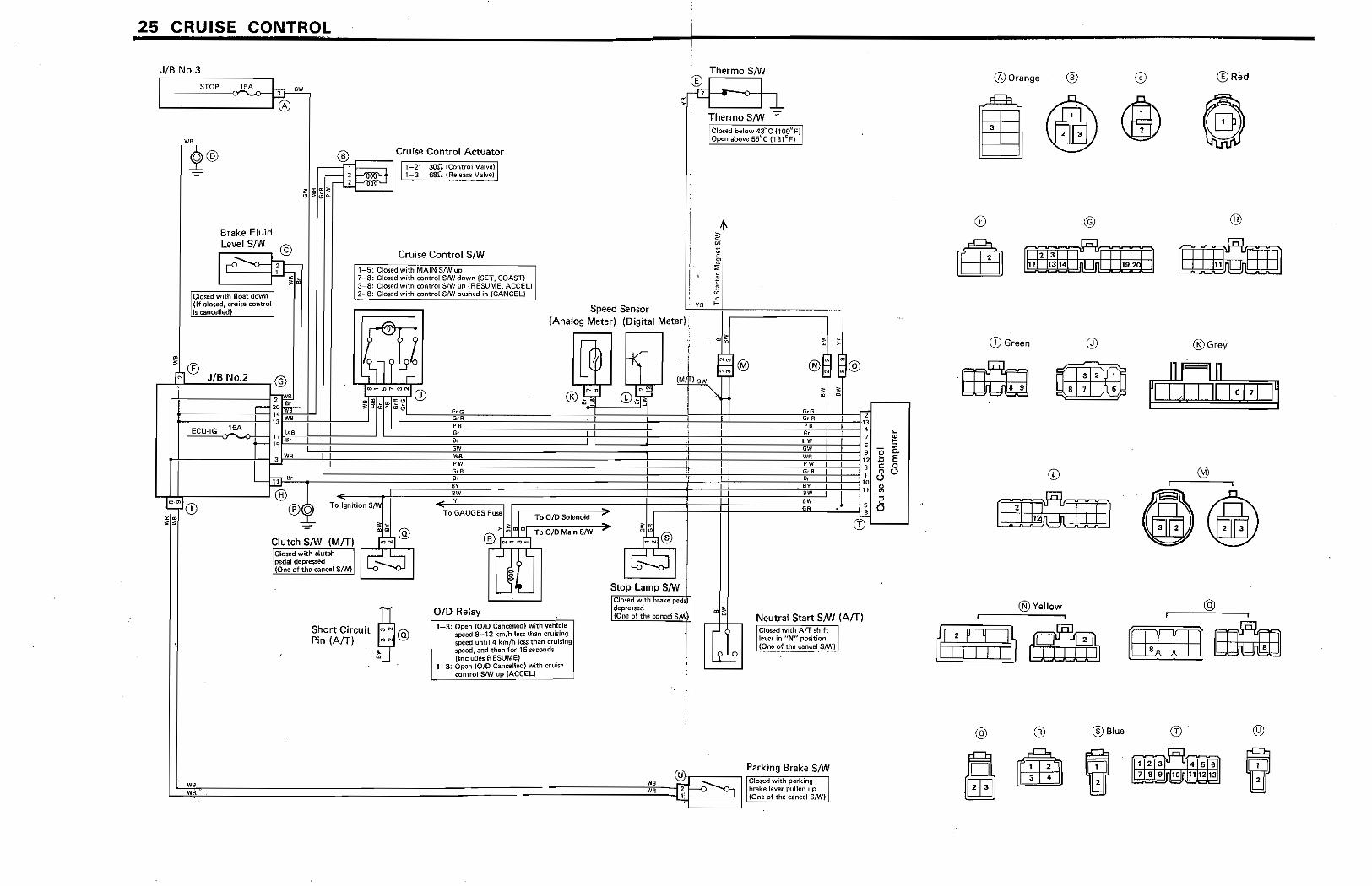
25 CRUISE CONTROL
JIB No 3
I STOP lSA l "'
L--_---..J!®
Brake Fluid LevelS/W © r" ....... -0 n
'l
I
Closed with float down I (If closed, cruise control I'
lis canoolled) I
® Cruise Control Actuator
13 ~ I ~-2: 30.n (Control Vallie) j12~ ~-:~: .. ~~~ (Release Valve)
Cruise Control S/W ~.",-~~ : 1-5; Closoo with MAIN SfW up , 7-8:: Clo~d with control S/Wdown {SET, COAST} : 3~8: Clo~ed with controL SJW up (RESUME, ACCEl) : 2-8: Closed With C?~!ro( S/W pulhed in (CANCEL)
Thermo S/W
...::m I "'-i I ~
Thermo S/W -:" ici~;d below 43"'C (109"F)f : Open above ss"c 031~F) !
t !
Speed Sensor L'..'V,-,,-R-'t >=-;=======1 (Analog Meter) (Digital Meter),
~rv
r-~;;j ®_F~ JIB: No~, .. 2 ---,@'!li r ~:o ~==~-;~~~~;;J,r~c"~W-~;~m~0
-"E=..:.::Cl)'[G'-c~,...,·1·_5A -O+~-II" I l<;B
t-t--------+-If2.IWR ~ B. .='
L....t-:!:r------l @ I;~J<D ~ ~;
l..,@ Clutch S/W (MfT) 'I : CIO$tld with clutch r--' ~JI;,:.:;L-.L~I : pedal depressed I -... I lane oft'" "".", SNiI '-0 '<>-'
,"ortO,,~;, D@ Pin (AfT) M N Q
1;
~ 'I.
(~ W- '!~ 1M' I 'i 1M, !nAW ,-:::"'"'
® !;:~ © 1i!iJ "" "G
010 Relay 1 3: Open (0/0 Cancelled) with vehicle
speed 8~12 km/h lessthan cruising speed until 4 kmfh less than cruising speed, and then for 15 seconds {Includes R ESUMEj
1-3: Open (OlD Catll;elll!d] ...mh I:fl.,lise L----.... ..... ::?f!(toj SIW UP {ACCEU
, , : ,
Neutral Start S/W (AfT) ;·6i;n;d with Arr shift i lever in "N" position : l (One of the cancel S/W) i ...... ---,
( ""U}r---~ Parking Brake S/W
c:================================JW1!::B~m;'---E:;; - Ctpsedwith parking , Pi. -0 ~ brake 1«'If!-( pulled up : I r {One of the cancel S/W} i
@Orange ® @Red
3
® @ @H '.
CD Green 0 @Grey
~ ~ • 7 5 ~I~ 1.1 7 1 I~
i l
.~@)
@ ® @Blue @
, 2 3
7 ••
® ®
STOP 15A
(Digital Meter)
ECU-IG Jill~~ r~~!!::!T---' 15A
- .. -- ..
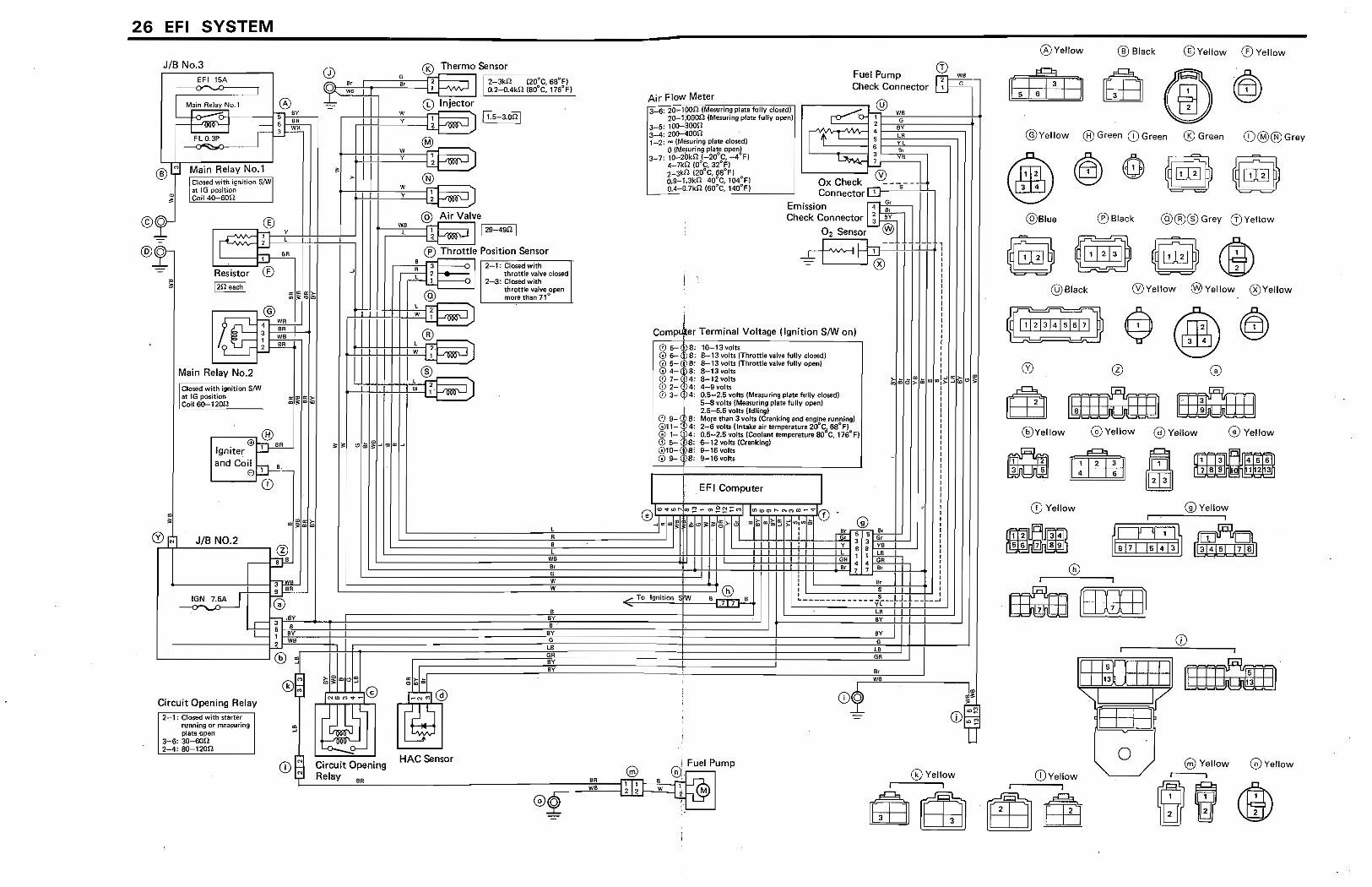
26 EFI SYSTEM
JIB No 3
EFI 15A -----~
®;:I Main Relay No.1
I :CIOSBd with ignition S/W at IG position
~ eon 4O-00n
©o ® , I
, h
I
Resistor ®
y t
66
r--"" ® Ell "'" S" Igniter rJ-t
and Coil h-1 ,
L __ E)...IJ...
CD
" @ r"l JIB NO.2 r--r,L-"':::':::":':':=--..., @
T'
w y
® U:~J
@ AirV.lve ~ I r:12;;:'~4C;;;gn"l
® Throttle Position Sensor
F::±:i' . 3 , ~OSed with 1.. ~ , throttle valve dosed ~ j 2-3: Clored with
@
;. r~J throttle valve open more than 71<>
l
l W,
Fuel Pump Check Connector
Terminal Voltage (Ignition S/W on)
@ ~-' :: 10-13'101($ G? ~i 3: 8-13 volts (Throttle va:l1H! fully closadl
~! ~ t! I J: t g:::: (Throttle valve fully open)
@ 8-12votts @ ?~: 4-9 volts @ )4: 0,$-2.5 volts (Measuring plate fully dosed)
5-8 volts !~ruring plate fully opel'll 2,&-0..5 Yom (ldli!lgl
(f) 9- -S: More than :3 volts iCraJ'lldng and englM running) 011-" 4: 2-6 volts (Intake air temperature 2ifC .. SS"F) G) 1- 4: 0.5-2.5 '1olts (cOOlant temperature SO C,176"F) {95- S: 6-12 volts (Cnmking) @10- 8: 9-16 VOlts ® 9- S: 9-16voiu - ..... .
E F I Computer
~'\ !,O'<tw"'~::!""Q>e~;:M I<OO:'>C>,.. .... <':I:.:> ... ..,0 '-'ja:im; i m~J:~ffi:>-t51 ",~",t;.J)-<Qlu;m
fl
+-----------4---f~
8, G W W
Circuit Opening Relay 2-1; Oosed with starter
nmning or l'Masuriog plate open:
3-6: 3O-€l():Sl 2-4: ~12OSl
G
CD $ Circuit Opening HAC Sensor @ Gl. ~ump ~[ __ R~el=a~y __ ~'~R ____________________ ------__ ~-;:::::mBR[:::[~l[l1~l]:=i.::~·:~ @.2 .• ~ w1f~
@Yellow
~ rn II .,
o Yellow ®Black ®Yellow ® Yellow
[[51 :PHI @Yellow ® Green CD Green ® Green (i)@®Grey
@Blue ®Black @®®Grey (!lY.llow
@Black ®Yellow @'iYellow ®Yellow
~
@Yellow Yellow @Yellow 1::V Yellow
~ tttjjj
CD Yellow
ffi'l2iIFilIf3i.i) ~
I
I 15) , I I I I
"'-
CD Yellow I
lt13Jrn
113 h nil 1
/ , I
0 ,
G)Yeliow i
~ ~
CD i
@Yellow o Yellow I
®Yellow
(i)@@Grey
) Yellow
@Yellow
) Yellow
, li4'f5'Fsi1 ~
@Yellow
EFI Main
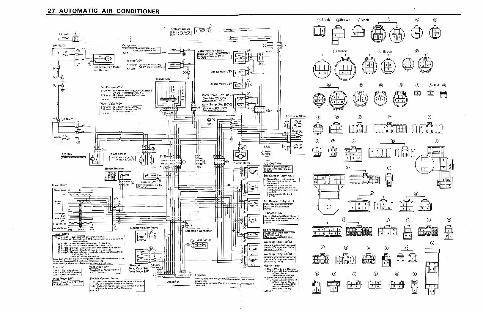
27 AUTOMATIC AIR CONDITIONER
@ ~J/B No.2
Ale 8/W LC;:?"*c Witfi M\ pu~lir!0l
Power Servo
"I
!I
Double Vacuum Valve
I~
Rheo~tat
Heat Mode S/W Vent Mode SIW
e . " , , , '
1 t-+--... , ,
I Amplifier
" L
1080 • ". Inspection Connector
@ Solar Sensor
~ I'~ -'~-----,
Ale Relay Block
@Black @Brown @Black @ @ ®
CD Green (J) Green ®
@@ecj)$@ @Blue ®
® @
@
rrmn, m-
iffifG9IE '15 '
"" 1/ I I
0
[~JIDl~ o [)
I
rn±Qm) m @
I
~ ltmEJ
[)
~~5~4~-+~3~T-+~1 If~d!'~JijU4~'~ 13 12 11 9 8 1 ~ 7 a 9 111 1
~ ~
4 6
.6:II':n. ~
®
@
[)
11 2 .3 4 .?67a~
2
3.
m ~
®
10
rn 01
GAUGE 7.5A
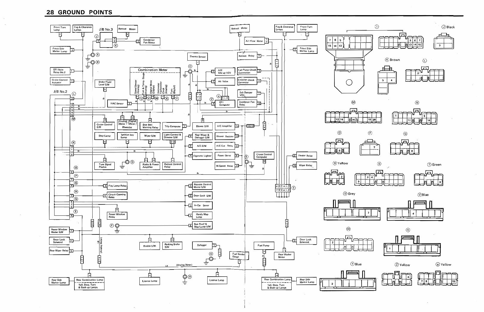
2 8 GROUND POINTS
j l Fco,tT~, J Fog &: Ci"earal'l.Ott ump [R~tr2ct MotOr J Lamps
lJ 3 ! ,: I,. I!I
"'''',,'' Mot~ l Front Turn J I fog & Clearanre JIB No,3
[Ai' FI~ M'''jlJ=
Lamps.
j:l
-rn Front Side J
Lamp
, ~ Marl(er Lan-,p
'\
't ~ Q) 4 -rrI Condenser
J -{! L , Fan Motor
'® ,~- !-4 Retract Rf"laY?
p
l FrcmSidf' p I Thermo Sensor
-• -
Marker Lamp
a@
© '? , k 1® J Fl.le'F'-ompChecr Ale SV Connettioli
~r 2
IdhH1P V Combination M..::e.!:._ --
--,
..., t-----f------
J ~mi$Si(m Check 2 I
l EFIMain p---rrl Ai, V.," ""M~~ : I
Relay No,2
t!J ri II ... E
~ • I
I ~- 5 :Ii: .. -
@ 0]U t_ Su~ Oampef J!ll I
t Cruise Control P Brake FIUidJ
-E = 1i ., I
Le~'tl! S/W In"" f-g; .. ~ EO~~ r-
;-; VSv.:
I
Actuator
'g~ ~;;; '&:2> zg] t::: '5
I
I
~~ §~ Be >1-0::' 1-_
~ ,~
I I;::;;, r Cond~nser Fanjfr- I :~@1: ®!?® 'T® f<D
I
JIB No,~ (i)
! 1:] " -:m EFI Relay: , ....
Computer
I
~:
... 3
HAC"",", }D 'I I I
i m1-~ ······r~~ "
~
" R 1L.B. A _
---19
"'" ~ l~
" "
J l AiCAm~m" Fl' 'Anal 19lta
BmwI#' SNJ
@ (M'''('j ~,w,'
Seat Belt' J t Trip Computer ,
L
CruIse eontroJ Rheo$1at Warning Relay
Rear Wiper & J I Blower Resisf{;r ~
i SIW
J r Ugh< (;e""" &J DefoggerSNi Ignition key J I Wiper SfoN
Oimm&SIW Step Lamp J Lamp
jJ ! IAlC Cut Relayr jl --A/C$IW
HeatH Relay J , @ j, 'I.
@ Cruise Contra I J ,
~ J l rom' ""0 jD- Computer
m e,
4 C.garettll Lightllr
~- j lfliper- Relay"
,'J~~ iii.
1 ~ I "~Con"oJ ,.
'-- H
[Hi-Speed Rtllay ,
, 11 1j?)@ r RadiO" ~ poweJ ~:Iay
! I Tum Sigoal
Atnpltfler
J Flasher -
" , @
,
61-
I: ",'::~e<",!! (i)
r-®
. --af Remote ControJ 1
'<>~~<nhl.J
I-;'L
2 Minor S/W
1J.lli
ffa' ..r:MFog Lamp R-e!ay
2 Door lo,* SMJ
1iiL~
J -
, ® -£If Circuit Openil'lg
~ In-C., S.M' J t;"t , "my m,® ~L
..B ~ Hendy Map J
~~
Lamp
"
(j) r Power Window
cq Son Roof & I
m Relay r I •
Map Lamp S/W
• ®~
~ Ooorlo~ J
~
i 3 Solenoid
POWllf Window p'
11 13. I Fuel Pump
MID" SIW }J P-: R
Oefogger
UI ~
I J [ Parking BT;ll:;e
9 I Rear Washer
OGor Lock J
Suckle SIN srw
-~'"
@ l Fuel Sender • Motor
Solenoid
{ - G,,,,,
~
Rear Wiper Rela~
" ..c©>- JI -
- m
(Analog M!fter)
m
" -
CD I
Q) Black
.1.:01111 ~ @Brown
[ I I 1
o
®
~ ® @
Qrn~ (i) Green ®Yellow ® / ~
eaa~~ @Grey
~I ~J. I II~ 1 ,I,' 1 Ij ~rl ~! !I~i ~~~rr==I,::::::I~ !~Ij ®Blue
I I I
@Yellow G) Yellow
B Rear Side j 1i B
Rear CombiflatiO/l Lamp H Marker Lamp
O® I U=re .... mp J ----11
r' Tail, Stop. Tum [ UOlnse Lamp J
& B~ck·up lamp$ -
Rear Combination Lsmp l Rear Side j-- ----------- -Marker Lamp Tail. Stop, Tum .& Ba;j.:,up Lampi
I i
)Slaok
~ :jJ
lIow
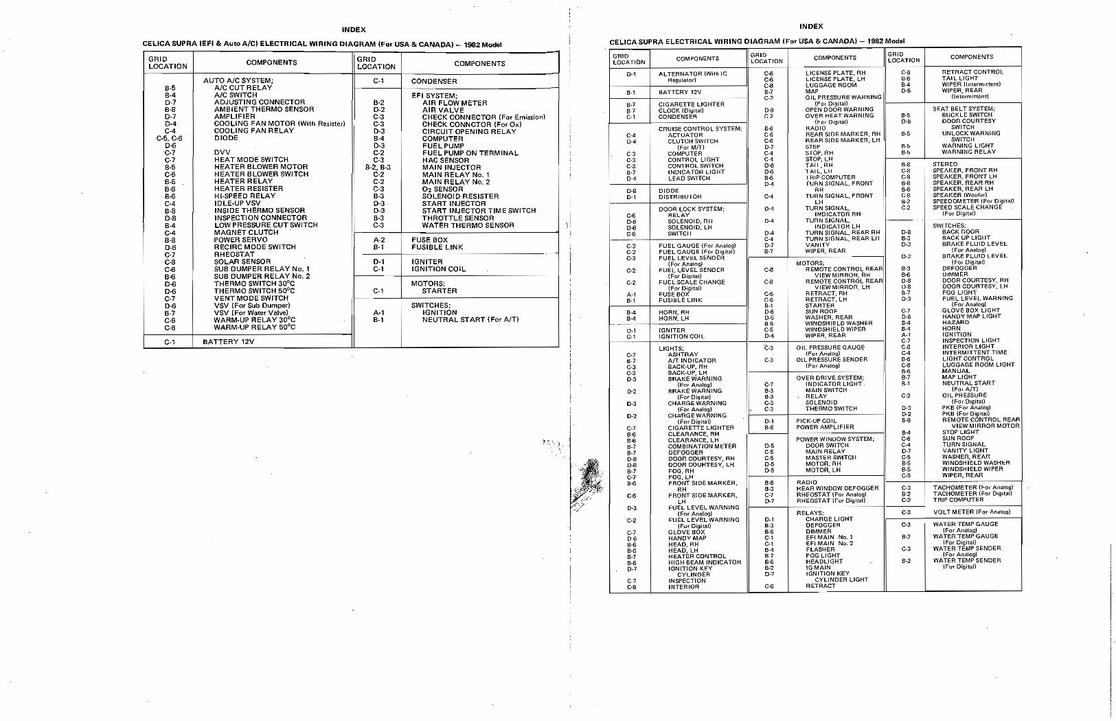
INDEX INDEX
CEUCA SUPRA (EFI 8< Auto AlCI ELECTRICAL WIRING DIAGRAM (For USA 8< CANADA) 1982 M_' CELICASUPRA ELECTRICAL WIRING DIAGRAM IFor USA 8< CANADA)- 1982 Modol
GRID COMPONENTS GRID LOCATION LOCATION COMPONENTS
AUTO AIC SYSTEM; C·, CONDENSER 8-5 AIC CUT RELAY B·4 AICSWITCH EFISYSTEM; 0-7 ADJUSTING CONNECTOR 8·2 AIR FLOW METER 8-8 AMBIENT THERMO SENSOR 0·2 AIR VALVE 0-7 AMPLIFIER C·3 CHECK CONNECTOR (For Emission) 0·4 COOLING FAN MOTOR (With Resi,ter) C·3 CHECK CONNCTOR (For Ox) C-4 COOLING FAN RELAY 0·3 CIRCUIT OPENING RELAY
c-5, C-6 DIODE B-4 COMPUTER 0-6 0-3 FUEL PUMP C·7 DVV C·2 FUEL PUMP ON TERMINAL
GRID COMPONENTS GRID ! COMPONENTS GRID COMPONENTS LOCAilON : LOCATION: LOCATION
D·l ALTERNATOR (With!e C-S LICENSE PLATE, RH 0-6 RETRACT CONTROL Regula,or) C-6 LICENSE f'LA TE, LH 8-8 TAil UGHT
C-8 LUGGAGE AOOM 8-4 WIPER !lntefmitt~nti ! .-1 BATTERY 12V 8-7 MAP D·5 WIPER,REAR
C-2 OIL PRESSURE WARNING: {lntermiuemj
8-7 CIGARETTE LIGHTER ! {For Qi."ital) 87 CLOCK {Oigltafi O-S OPEN DOOA WARNING SEAT BELT SYSTEM; C·l CONDENSER C-2 OVER HEAT WARNING 8-5 BtJCKLE SWITCH
(For Digital) 0-8 DOOR COURTESY CRUISE CONTROL SYSTEM; B-6 RADIO SWITCH
c·, ACTUATOR C-6 REAR SIDE MARKER, RH 8-5 UNLOCK WARNING
D-' CLUTCH SVVITCH C-6 REAR SIDE MARKER, lH SWITCH (For MIT) 0-7 STEP , 8-5 WARNiNG LIGHT
C-3 COMPUTER C-4 s-raf', RH B-. WARNING RELAY
C·7 HEAT MODE SWITCH C-3 HAC SENSOR B·5 HEATER BLOWER MOTOR B-2, B·3 MAIN INJECTOR C·5 HEATER BLOWER SWITCH C-2 MAIN RELAY No. , B-5 HEATER RELAY C·2 MAIN RELAY No.2 B-6 HEATER RESISTER C-3 02 SENSOR I B-6 HI-SPEED RELAY 8-3 SOLENOID RESISTER C-4 IDLE·UPVSV 0-3 START INJECTOR 8-S INSIDE THERMO SENSOR 0-3 START INJECTOR TIME SWITCH D-8 INSPECTION CONNECTOR B-3 THROTTLE SENSOR
I 8-4 LOW PRESSURE CUT SWITCH C-3 WATER THERMO SENSOR C-4 MAGNET CLUTCH B·8 POWER SERVO A·2 FUSE BOX 0-6 RECIRC MODE SWITCH 8·'
I
FUSIBLE LINK C-7 RHEOSTAT -----~ .... -~~~---
C-B SOLAR SENSOR D·' IGNITER C-6 SUB DUMPER RELAY No, , C·, IGNITION COIL B-6 SUB DUMPER RELAY No.2 0-6 THERMO SWITCH 30°C MOTORS; D-6 THERMO SWITCH 500C C-' STARTER C-7 VENT MODE SWITCH
! 0-6 VSV (For Sub Dumper) SWITCHES; B-7 VSV (For Water Valve; A·' IGNITION C-6 WARM·UP RELAY aooc 8-' NEUTRAL START (For AlTI C-6 WARM·UP RELAY 50°C
I C·, , BATTERY 12V
C-3 CONTROL UGHT C-' STOP, LH C-3 CONTROL SWITCH D-6 TAIL, RH 8-8
I
STEREO 8-7 INDICATOR LIGHT 0-. TAIL, LH C·8 SPEAKER. FRONT RH
D-' LEAD SWITCH B·6 TRIP COMPUTER C-. SPEAKER, FRONT LH 0-4 ,URN SIGNAL, FRONT 8-8 SPEAKER. REAR RH
D-8 DIODE R" 8-8 SPEAKER, REAR LH
D·l DISTRIBUTOR C-4 TURN SIGNAL, FRONT C-. SPEAKER (Woofed LH B-' SPEEDOM ETER ,Fa. Digital)
DOOR LOCK SYSTEM; [}-4 TURN SIGNAL, C-2 SPEED SCALE CHANGE
c-6 RELAY INDICATOR RH {For Digita!l
0·6 SOLENOID, RH 0-4 TURN SIGNAL, 0-6 SOLENOID, LH INDlCATOR LH SWITCHES;
~~ SWITCH 0-4 TURN SIGNAL, REAR RH D·B BACK DOOR 0.4 TURN SIGNAL, REAR LH 8-3 8ACK,UP LIGHT
C-3 : FUEL GAUGE (Fo. Analogl 0-7 VANITY 0-3 BRAKE FLUID LEVEL
C-' FUEL GAUGE (For Diyitul) B-7 WIPER, REAR ! F or Analog)
C-3 FUEL lEVEL SENDER ........ D·' BRAKE FLUID LEVEL
(For AI'Hidog} MOTORS; (For Digital)
C-' FUEL LEVEL SENOER Co. REMOTE CONTROL REARI .-3 DEFOGGER
{For Digltall ! VIEW MIRROR, RH : .<l DIMMER
C-2 FUEL SCALE CHANGE C.g REMOTE CONTROL REAR: O-ll DOOR COURTESY, RH {For Digitall VIEW MIRAOR, LH O-S DOOR COURTESY, LH
A-l FUSE BOX C-6 RETRACT,RH 8-7 FOG LIGHT
.-1 fUSIBLE UNK C-6 RETAACT,LH 0-3 FUEL LEVEL WARNING 8-1 STARTER (For Analog)
8-4 HORN,RH
~~~I 0-. SUN ROOF C-7 GLOVE BOX UGHT
B-4 HORN, LH 0-5 WASHER, REAR D·. HANDY MAP LIGHT -~- B-. WINDSHIELD WASHER .·4 HAZARD
D·l IGNITER C-5 WINDSHIELD WIPER 8-4 HORN C-l IGNITION COil 0-4 WIPER, REAR A-l IGNITION
C-7 INSPECTION L-IGHT
LIGHTS; ¢C·S GIL PRESSURE GAUGE C-8 INTERIOR LIGHT
C-7 ASHTRAY lFor Analog) C-4 INTERMITTENT TIME
S-7 AfT INDICATOR C-3 OIL PRESSURE SENDER 8-8 LIGHT CONTROL
C-3 BACK-UP, RH : (Fot Analog) C-8 LUGGAGE ROOM LIGHT
C-3 BACK-UP. LH :~. B-6 MANUAL
0-3 BRAKE WARNING OVER DRIVE SYSTEM; 8-7 MAP UGHT {For An;llog} C-7 INDICATOR LIGHT B-1 NEUTRAL 5T ART
[}-2 BRAKE WARNING B-l MAIN SWITCH (For A/T) {For Digital! B·3 RELAY C-2 OIL PRESSURE
0-3 CHARGE WARNING C-3 SOLENOID (For Digital) (For Analog) , C-3 THERMO SWITCH D-3 PKB (For Analog)
0-2 CHA'RGE WARNING 0-2 PKB (FtH Digital! {For Digitan 0-1 PICK-UP COl L B-8 REMOTE CONTROL REAR
C-7 - CIGARETTE LIGHTER 8-8 POWER AMPLIFIER VIEW MIRROR MOTOR
B-6 CLEARANCE. RH . 8-4 , STOP LIGHT
B-8 CLEARANCE, LH POWER WINDOW SYSTEM; C-6 SUN ROOF
8-7 COMBINATION METER 0-5 DOOR SWITCH C-4 TURNSlGNAL
8-7 DEFOGGER C-5 MAIN RELAY 0-7 VANITY LIGHT
D-8 DOOR COURTESY, RH C-5 MASTER SWITCH C.5 WASHEfl,R€AR
0-8 DOOR COURTESY, LH 0-5 MOTOR,RH B-. WINDSHIELD WASHER
8-7 FOG, RH D-5 MOTOR, LH B-' WINDSHIELO WIPER
C-7 FOG, LH i C-5 WIPER, REAR
8-6 FRONTSIDE MARKER, 8-. RADIO
!
RH B-3 REAR WINDOW DEFOGGER C-3 TACHOMETER (Fo.r Analog}
C-6 FRONT S[DE MARKER, C-7 RHEOSTAT {For Analog) B·2 TACHOMETER {For Digital!
LH 0-7 RHEOSTAT (For Digital! C-, TRIP COMPUTER
D-3 FUEL LEVEL WARN~NG (For Ana!ogl RELAYS; C·3 VOLTMETER {Fur Analog)
C-2 FUEL LEVEL WARNING 0-1 CHARGE LIGHT (For Digital) B-3 DEFOGGER C-3 WATEA TEMP GAUGE
C-7 GLOVEaOX 8-6 DIMMER (For Analogi
D-6 HANDY MAP C-l EFI MAIN No.1 8·2 WATER TEMP GAUGE
B-6 HEAO,RH C-l EFI MAIN No. '2 IFor Digital)
B-6 HEAD, LH B-' FLASHER C-3 WATER TEMP SENDER
8-7 HEA lEA CONTROL B-' FOG LIGHT iro. Analog)
8-B HlGH BEAM INDICATOR 8-6 HEADLIGHT .-2 WATER TEMP SENDER
0-7 IGNITION KEY 8-2 lGMAIN (For Digital)
CYUNOER 0-7 IGNITION KEY C-7 INsPECTION CYLINDER LIGHT C-8 INTERIOR C-6 RETRACT
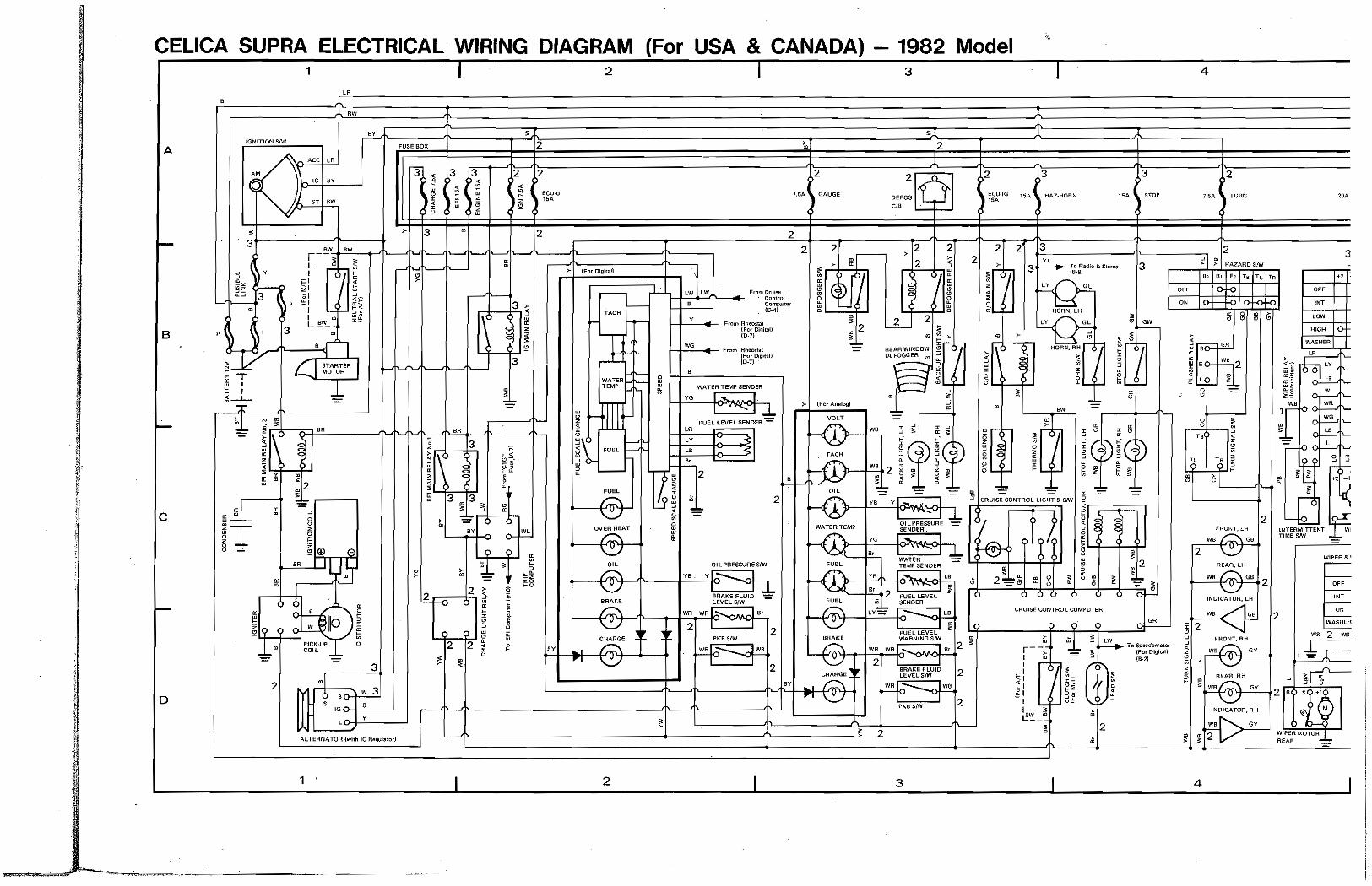
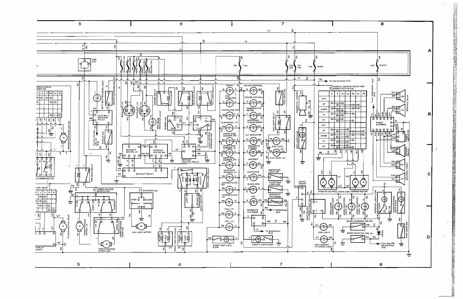
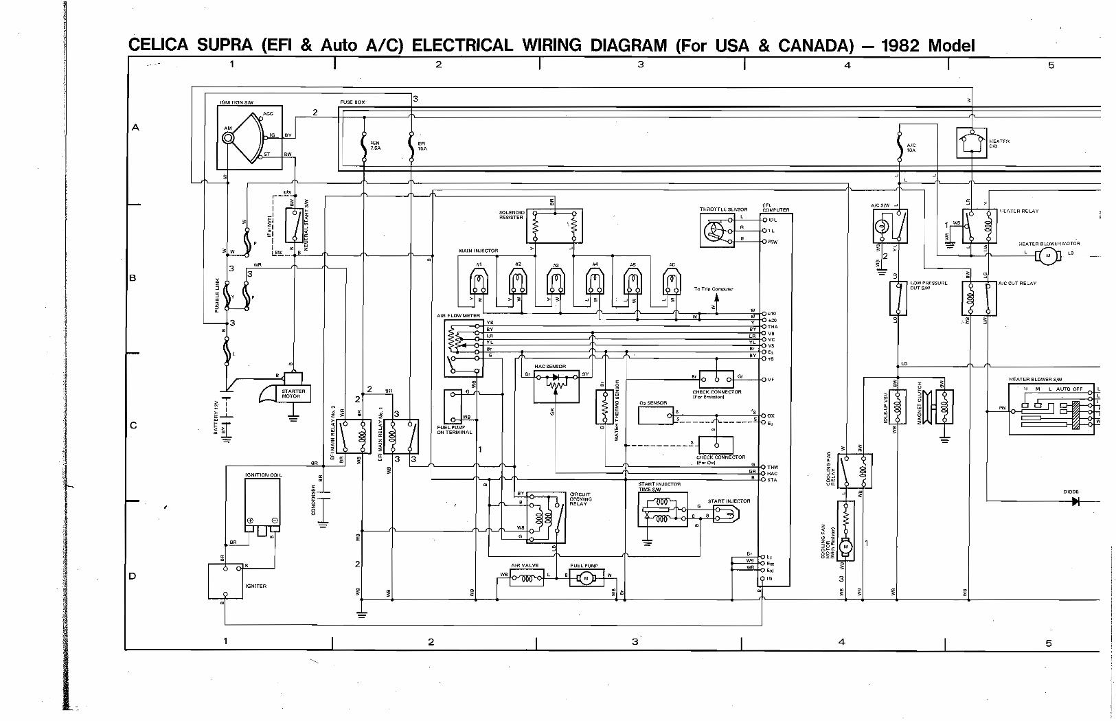
CELICA SUPRA ELECTRICAL WIRING DIAGRAM (For USA & CANADA) 1982 Model 1 2 3 4
'C~LR~~~~~~~~~ RW
~ ~ ~
lG(>41T10N SIW !'lISE BOX 2 ~ 2 A
B
c
D
ACC LA
It> i\V
ST ""
Y
3 , l} •
~ /--t--:::;a:iS:-R~l,R ~~ /' MOTOR ,.,- '--
ffi , ~ , ~~
6
2
w ~Ip PlCK4JP COB ..
• 3
w 3i 6 , $
'oo-+-"'-_.J y
AI. TERNATOR iwilh Ie ~Iat"d
1
2
:1
,y
>- tFw Digita))
-, ... ,
WATER TEMP
2
,
F'rcm HhiIDmM (1'$< 01(jit8l1 (0.1)
WATcH TEMP SeNDER
~~ FUEL LEVEL S€NOER ':"
LR
LY
-.;
2
OILPRESSOI'IESlW
ya vl':---" _I
2
7.51\. ) GAUGE
2 2
(fo, Arn!log)
,
2
2
2
I~ j L.+-(....:,:.J~
3
2
2
~ ECU·fG , ,"
:1
•
or-
II~ ~L.....:
~
3
2 3
CRUISE. CONTROL UGH;!.'< SfW
? ,J
CRUISE CONTAOl COMPUTER
•
3
1511. I s-roP
3
2
H:;A TURN
:: I ~ HAZARD SNI
2 3
" or.. IN.
~-~r-+ ffi8;jj:0 LOW f-----,~
RE~LH
we f ........ \GB 2 -;;::;J
INDIC<rATOR'I.H
+--"w::.' -< os
~2 :J "RONT, RH
<l. WBQ GY
* 1 ~ !
4
HIGH 10
2
2 , "
WIf'<iR MOTOR, I REAR -=
R
,SHIELD WIPER SHeR SNf
l~$+S-S
--v
CO WWER MOTOR , I sm. REAR....I I
, w
1
5
• 2 •
If) 2
2
y
5
6
" ~
Qw MOTOH.AH
6
7
3 w
,..-----,3
J <All.
7
2
2 2
e'G "A
2
8
A
2
AAOIO
2
/
c
D
-~
8
Jill IlI!!IEi'i1 1111111 111111 'r'W "9,"" ,",,,,,,c,c,,,,,,,,c,,,,, ,
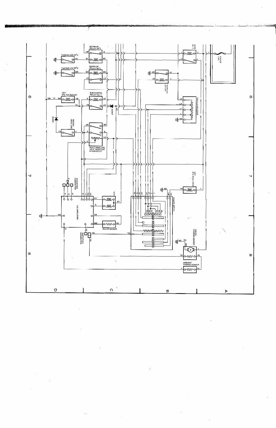
I WARM-U' flEU\V 31)"C
lW R e h"" THERMO 8m 30~C
.:::s 1";;: ">
y
IlL .Jr. ,hG DC
'" .~M~ '" lR
_0 l"-
WARM-UP ,
THERMO S,W 50°C RELAY 50°C
III ~ ,IGW SA .MO_ SR II' WS La c'l I ---"'1 '" -
lO LG "'",,000 Y
----- ~! VSV SUB OUMPEH
(J) {Fer Sub Dump*d AELAY No, 1
W, - WS hM ,I y, B cA"" lR lS
I -Iyol LR va l..... CO ~
'~ 5
5 CY
0 L m
~. ~ II' w, g JI '" m
'R
-...!: ~ vJ!\. ,Iv • .C f-!l... I -"":-1 ,,,--::: YO
------
0 J HEAT MOOS S/W, VENT MOPE sm &R!-IEOSTAT
I ::;:;; .< 0 ~
--.j
~
{~( ~ ] !
Ii~ ye """ , Y
0 0 11 G5 ~C;rr I ci
:I'l,o :;.; til ....; ~ b < r -< < .>
GY :::J 3 F • ~
> G ~
~
~ii'~gii' > <
~ 0
,I W£ ~ GR
" ;; II >
9 IWR .IGR -, L-o ~
• < SOLAR SENSOR ,,m, ~z 0
8" ,vc. mia YO .U 2m z~~I~ 0
~~ ~ III WB '" ~ Z • • 2 il ~
140 l
----- yo " 0:>
AMBIENT THERMO SENSOA
, ------ , ' I" .' '.
o o III
y II
~
~o .> >0
0 m
J (J)
, --.j
0:>
»
Prepared by
TOYOTA MOTOR SALES CO,LTD.
Oversea. Technical Department
Maruhl Center
First Issue: September 7,19B1
Publication No. 98955
Printed in Japan
..... _-_. -.-....... --.----.--~~~~-