Embed Size (px)
Citation preview

Univers
ity of
Cap
e Tow
n
UNIVERSITY OF CAPE TOWN
DEPARTMENT OF CIVIL ENGINEERING
.,
THESIS FOR M.SC. ENGINEERING
"THE OPTIMUM DESIGN OF FLAT RECTANGULAR CONCRETE PLATES
SUPPORTING LOADS IN BUILDING STRUCTURES
AND TESTS ON A ONE-THIRD FULL SIZE EXPERIMENTAL MODEL".
·<BY
EDWARD GROYER, Pr.Eng., B.Sc. (Eng) M.I.Struct.E
A.M. (S.A. )I. C. E. (S.A. )Cons.E.
Univers
ity of
Cap
e Tow
n
The copyright of this thesis vests in the author. No quotation from it or information derived from it is to be published without full acknowledgement of the source. The thesis is to be used for private study or non-commercial research purposes only.
Published by the University of Cape Town (UCT) in terms of the non-exclusive license granted to UCT by the author.
;
IN DE X
S Y N 0 P S I S
PART 1 INTRODUCTION
PART 2 STRENGTH AND BEHAVIOUR OF FLAT PLATES
SECTION A. Ela.Rtic Theory
B. Ultimate Strength in Bending of Flat PlateR
C. Punohine; Streng·th of SlabA
D. DAflnotinn o~ Flat PlatnR
D.l Alternntive Methods of Deflection Prediction
D.2 Indirect Control of Deflection
E Methods of Design of Flat Plates
E.l
E.2
EE
EE.l
EE.2
EE.3
F.
F.l.l
F.l.2
F.1.3
F.2
F.2.1
F.2.2
F.3
F.3.1
F.3.2
G.
H.
H.l.
H.2
H.3
H.4
H.5
H.6
H.7
H.8 .
H.9
H.lO
H.ll
H.l2
H.l3
Elastic Method
Empirical Method
Examples of Plate Design
Elastic Method
Empirical Method
Yield Line Method
Elastic-Pla.stic Analysis and Direct Design
Elastic-Plastic Analysis
Summary
Distribution of Moment across Panel width
Direct Design for Optimum Criteria
Design procedure for Reinforced Plates
Elastic-Plastic Design Example
Behaviour of a Pre-stressed Plate
Design Procedure
Design of a Pre-stressed Plate
Finite Difference Method
Experimental Flat Plate
Description
Design Loading
Specification
Erection Procedure
Concrete·Sample Tests
Curing
Loading Arrangement
Instrumentation
Purpose of Test
"Exact" Analysis by Finite Differences
F,ffect of weight of Brickwork
Plate Flexural Rigidity
Testing Procedure
P.T.O.
Pa~e.
I
1
4 7
10
F .:J
19 21
24.
28 \
31
48
51
54
59 60
63
63
64.
69
73
79 86
91
91
91
91
91
95
95 96 96 96
102 102
103
SF.CTION I
I.l
1.2
1.3
1.4
I.5
I.6
I.7
I.8
I.9
I.lO
I.ll
I.l2
I.l3
I.l4
J.
PART 3
PART 4
..
-2-
Results of Tests
Tests on Concret~ Specimen
Tests on 8mm diameter Steel Rods
Preparation of Load-deflection Curves
Corrections to measure deflection
Cracking Load
Slab Behaviour
Yield of Reinforcement at Column Edge
Punching Strens-th
Ul t].mate Load
Computed Deflections
Moment Variation across Panel width
Hall Behaviour
Test Short-comings
General Test Conclusions
Conclusions ·
Rb~FERENCBS
APPENDIX
FIGURE A.Fl
.FIGURES A.F2 - A.F6
TABLES A.Tl A.T2
FIGURES A.F7 - A.Fl3.
·PHOTOGRAPHS
BEFORE TEST A.Pl - A.P3
AFTER TEST A.P4 - A.P8
FIGURE A.F.l4
104
104
104
115
116
117
.119 122
122
124
125
128
129 130
132
136
138
·139- 143
144 145
146- .;.._ 152
153
154 - 15.6
157
•
Page I
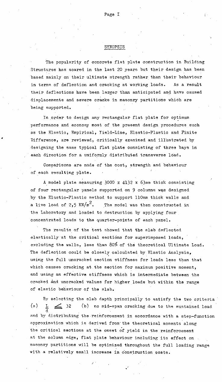
SYNOPSIS
The popularity of concrete flat plate construction in Building
Structures has soared in the last 20 years but their design has been
based mainly o:n their ultimate strength rather than their behaviour
in terms of deflection and cracking at working loads. As a result
their deflections have been larger than anticipated an<I. have caused
displacements and severe cracks in masonry partitions which are
being supported •
. In order to design any rectangular flat plate for optimum
performance and economy most of the present design procedures such
as the Ela.8tic, Empirical, Yield-Line, Elastic-Plastic and Finite
Difference, are reviewed, critically examined and illustrated by
d.esi.gning the same typical flat plate consisting of three bays in
each direction for a uniformly distributed transverse load.
Comparisons are made of the cost, _strength and behaviour
of each resulting plate. I
A.model plate measuring 3000 x 4132 x 63mm thick consisting
of four rectangular panels supported on 9 columns wej.s designed
by the Elastic-Plastic method to support llOmm thick walls and
a live load of 2,5 KN/m2 • The model was then constructed in
the Laboratory and loaded to destruction by applying four
concentrated loads to the quarter-points of each panel.
The results of the test showed that the slab deflected
elastically at the critical sections for superimposed loads,
excluding the walls, less than 80% of the theoretical Ultimate Load.
The deflection. could be closely calculated by Elastic Analysis,
using the full uncracked section stiffness for loads less than that
which causes cracking at the section for maximum positive moment,
and using an effective stiffness which is intermediate between the
cracked and uncracked values for higher loads but within the range
of elastic behaviour of the slab.
I.
By selecting the slab depth principally to satisfy the two criteria
(a.) L L 32 (b) no mid-span cracking due to the sustained load. d
and by distributing the.reinforcement in acoordancewith a step-function
approximation which is derived from-the theoretical moments along " the critical sections at the onset of yield in the reinforcement
at the column ~dge, flat plate behaviour including its effect on
masonry .partitions will be optimized throughout the full loading range
with a relatively small increase in c'onstruction oosts.
/ .

Page 1
PART 1. INTRODUCTION
"Flat Slab" structures can be described as reinforced
concrete slabs which distribute transverse loads directly to
a rectangular grid of reinforced concrete columns without
supporting beams. Either .or both column capitals and drop
panels are provided.
"Flat Plate" structures are a derivative and special
case of Flat Slab structures where the slab is of uniform
thickness throughout and the supporting ~olumns are either
structural steel columns with bearing plates or.reinforoed
concrete columns without capitals. It is not essential
that the columns form a rectangular array but this special
case will not be considered here.
In many parts of the world since the H'ar, Flat Plate
structures have become exceedingly popular, for multi-storey
flats and commercial buildings, with both the Builder and the
associated Professions. The reasons for this popularity
can be briefly ascribed to the following:-
1. The uniform under-surface is architecturally attractive
in that .it allows maximum flexibility in the sub-division
of internal space and the distribution of services.
2. Erection of formwork by the builder is simpler, quicker
and therefore cheaper than conventional beam and slab or
even "Flat Slab" construction.
3. · Placing of steel reinforcement is faster, in that beams
with small diameter stirrups are not required to be fixed
before the slab is commenced.
4. Engineers, once they have accepted the hair-raising
simplific~tion in the design permitted by most Codes of
Practice, learn to love them. This simplification
extends to the setting out Drawings of Structure and
Reinforcement as well as checking of steel placing.
5· The Client reaps the benefits of a more functional,
flexible and possible cheaper cost of construction
allied to an earlier completion date •.
Inevitably /
c
(.Rl?)
Page 2
Inevitably he will be sold. on "Flat Plate" construction
for all his other similar projects •
.Rarely in the History of the Construction Industry
has a form of Concrete Construction captctred the approval
and enthusiasm of all its participants as has the Concrete
Flat Plate. It is however surprising that in the design,
attention has been largely directed to their capacity to
ca.rry loads and that their behaviour in terms of crack.ine;
and deflection has-been largely nee;lected. Arbitrary
limitations to the ratio of spa~ are set by most Codes in depth
a similar manner to structural steelwork, with the intention
of providing sufficient rigidity to prevent excessive
deflections. The Australian Code for Concrete CA-2 1962,
the ACI Building Code 518-63 and the British Code CP 114,
iimit the ratio to 36 irrespective of span ratio, continuity,
superimposed loadine;, sustained loading or type of loading.
Whereas plates designed to this limit were shown by research
and experience to deflect initially less than the arbitrary
.§U2.~1'.?. set for all structures whether constructed in timber, .)60
steel or concrete (probably for aesthetic reasons),
seconrl.A.ry effBcts increased the d.eflection many.:..fold durine;
the course of time.
In the early 1960's flat plates which had. been constructed
a decad.e earlier began to show signs of distress in the shape
of visible cracks, abnormal deflection and particularly in
severe crackine; of brick partitions standing on the floor.
Figure Al in the Appendix reproduced from Reference 15 shows
one common mechanism of crack formation. Th1s brought growing
realisation that the deformation at working loads was as
important as the ultimate strength and that even moderate
deformation could cause damage to other parts of the building.
As a result of this, a comprehensive study of Flat
Plate structures was begun in 1959 by the Division of
Building .Research in Australia with the erection and testing
of four experimental structures as well as analytical ,
studies. The conclusions reached will be referred to at the
end of the Thesis, but the following observations will explaiti
the "excessive" deformation of Flat Plates compared tci ol"der
structures :-

(R37)
Page 3
), • In older forms of structure such as slabs Rupporterl by
deep beamR on all sides which were d.esignecl to carry
the full weight of masonry walls as well as the slabs,
many redundancies existed in the elastic interaction of
slabs, beams and walls which increased both beam and
slab stiffness. As a result computed stresses and
deflections were never achieved~
2. In slender flat plates the behaviour is close to the
design assumptions and all the old hidden factors of
safety are gone.
Westergaard reports one flat sl'ab structure built in
World War I where the columns were 5 ft. square at 20 ft • . centres resembling a Gothic Cathedral. A great deal of the
• load was carried by Arch action and not by bending. The
modern flat plate ha$ negligible arch action but is designed
by the same method.
3. Working stresses are now twice what they were 50 years
ago and with no significant change in the Elastic Modulus
of Steel, the corresponding strains and deformations
are twice those realised in the past.
Against the aforementioned. background of practical
experience and research still taking place in Australia and
also other parts of the world including South·Africa, the 1
writer proposes to discuss and predict the strength and
behaviour of flat plates at important stages of its life history.
The principal methods of analysis or design presently used
will then be critically examined in the light of these predictions.
A typical example will be fully designed by each method and
the relative cost of the resulting_slab will be estimated.
Based on these results, a proced.ure for direct design will
be selected which optimizes the behaviour of the plate throughout
its loading history for any given cost of concrete and
reinforcement. With a few small modifications this procedure
can be used for optimum design of plates carrying masonry
partitions.
· · As an illustration, a model plate will be directly designed
to carry average loading including brick partitions, and then
erected and tested to destruction to confirm or modify the
d.esign.

Page 4
PART 2. STRENGTH AND BBHA.VIOUR OF FLAT PL~_TF.S
(R34)
A. Elastic Theory of Thin Conc'rete Plates Sll.b,j ect to
Transverse Loads.
The following assumptions are generally made provided
any cracking is confined to small areas arounC!. the columns:-
1. The thickness of the plate is small compared to the
dimensions between the suonorts and the deflections are . .. small compared to its thickness.
2. The middle:·plane of the plate .undergoes no lateral
deformation.
3. Plane surfaces normal to the middle plane before bending
remain normal after bending.
4. Normal stresses transversely to the plate can be disregarded.
5. The plate is homogeneous and isotropic elastic.
It is convenient to set up three global axes at right
angles, OX, OY and OZ, so that plane XOY is horizontal and co-. .
incides with the middle plane of the plate before bending.
During bending points in the XOY plane undergo small vertical
displacements "w" to form the middle surface of the plate.
Any point in the middle plane of the plate is completely defined
by its X andY co-ordinates which are independent. The de-
flection under load "w" will then be a function of x,y and the
loading q, i.e. w = f(x,y,q). All other surfac~s in the-slab.
parallel to the middle surface are defined by their distance z
above are below it.
At any point x, y in the middle surface the following re
lationships exist'-
Slope • 7Jw .• · ..••• ( 1) of surface in X direction Lx - ~ -Slope
. {)w ••••••• ( 2) of surface in y direction = l.!1 -~
Curvature of surface in the X direction
.L = d2.w : •••• ( 3)
rate of change of slope rx --= = "() )<.~
I ()'aw ( . Curvature in the y.direction - ..... - ~· ... 4) r':f -
"btj2. Tv1ist of surface with respect to the X and y axes
•••• ( 5)

Page 5
The following relationships can then be proved :-
1. At any point, the sum of the curvatures in any two
directions at right angles ,is constant.
Fir;.2
2. At any point the maximum and minimum curvatures, called
the "·principal curvatures" occur in two directions at
right angles.
3. If 1 r
and 1 are the principal curvatures at any r
X y point, then 1 = 0 and the curvature and twist
If both r and r are positive the surface is "synclastio" X y
If r and r are of opposite sign, the surface is "anticlastic" X y
or saddle shaped. Further examples 'are points midway between
the columns in a flat plate.
' By considering an element of the slab dx x dy. x h where
h =. slab thickness at the point x, y, the following
relationships between internal moments and curvatures can
be established :-
M i:: D (..L x. r.>l.
M1=1>(~lj
( c? 'd't. ·) · - -"D ~ + V"""~ ••••••• (6) Q.)l. g ~:a.
(. ":\ 2. ""'\ '2 ') •••••• ( 7 ) .:;. - .. b (I w + ·v-- (/ vV
. Vc{l. ~
M,£ 1 ~ MJ>'- .D (1-'lr') d~vJ ) •••••• (8) ()·x. • -;; ';!
Again if l_ and 1 are the principal curvatures then Mx r r
and My ar~ the principal moments and Mxy = 0. If Mx and My
are known, the bending and twisting moment in any other
direction can be graphically obtained by a Mohr cicle. Mx,
My may be positive or negative.

(Rll)
Page 6
By further consideration of all the forces and bending
moments acting on the element which are shown below, and the
eQuations of eQuilibrium, the following basic plate e~uations
are d.erived :-
"'ll1 Mx · ·::z rl M "1 + () '1. fv1
·- ~ -~ •••••••• ( 9)
;:;
0 .x.z v '1-. )'j '() ~'2.
C>4-w + 2 )4- IN
+ '04-w = ey.D •••••• :(10) "d X 4 v ;..'2. 't><j~ ~ij4 () d:t
+~) - - Q.~~ ••••••• (11) -( w -0)l. 7; ..( 2.. -v '(} '2. .J)
C.l ( ()2w + 0'2. w) - - Q'1 •.•..• (12)
~· ~ ~.'" -0 'j ~ .D
where .. n == flexural rigidity per unit length
Ee ~,~
= IZ (I .... -,r~f
~ = transverse lbad per unit area.
Ec = Instantaneous Elastic Modulus of Concrete.
h = Thickness of slab.
iC' = Poissons ratio (0.15-0.25)
Mx, My, Mxy are moments per unit length expressed in force
units. ·
To find a soltition for a given plate it is necessay to
integrate (10) successively and determine the constants of
integration by satisfying the known boundary conditions.(Two per edge)
In this "day, an expression is found for "w" in the form of a
converging trigonometric series •.
By way of illustration for a simply supported SQuare .
plate a solution is
w = 1, "'4 j- ( 4 + A .. eneit ,. "r( :51 -+ B .... ..Jf'1 s .. t.. !:' Tj X s'"t.. ""'iiX) J) tr s""' ~ c::t. ~ ~ ""-
flo\ " I where m = 1, 3, 5 •.. • •.•••• • •••••• (13)
Am, Em are parameters to be determined from the boundary
conditions •.
Mx, My can similarly bA calculated from a converging series.
Design of fla.t plates a)(.
analysis reQuires that
Fj.g. 3
Slab Element

(R38)
Page 7
constants similar to those in the above eq_uation be obtained
by the satisfaction at a large number of points of bound.a.ry
con(litions which may change sharply from one panel to the next.
In view of this complexity and the vast amount of com
putation required to determine the bending moments at selected
points in order to proportion the steel reinforcement, the
method is not suitable for use in a design office. I
An approximate solution to the above with a small margin
of error can how~ver be obt·ained by the method of FinHe
Differences and this will be discussed in detail at a later
stage.
B. Ul,TIMATE STRENari'H IN BENDING OF FLAT PLATES:
For under reinforced sections, the plastic moment ci>f
resistance or ultimate moment per unit width of slab
by various Codes as follows:-
CP 114 m = p fyd2 (1- 0.75
pfy ) ..... u
ACI-315-68 m = p fyd2 (1- 0.59 .E£1.1) ..... fc
where
Both
./:' 1 . or .l.C
m = ultimate moment per unit width
p = reinforcement ratio
fy = yield stress of the steel
d. = ·effective depth oft the steel
u = concrete cube strength
fc1 = concrete cylinder strength.
formulae are identical if 9.!12 = u
0.79 u which is generally accepted •
is given
(14)
(15)
C E B ~ ( 1- ~) h1 ... p~ ~l.\ whe..r.e. ~ = sr.u{ s·l-re~S' 2
v;:,Ll ::::. o-;'2. (_ J. :2.- ~p) c:r-' =::. 0• 2. p l'e>o f -srr-~ss. 0·'2.
w P(/'~/o I . I
~ C. "jim.::>( er s h· e '""l"-- o-~r o- ~tit For convenience formulae (14) will be used.
Consider a continuous fla.t plate on columns at "L" centres
in the one direction ;;mel 111" centres in the dir13ction at :fight
angles and req_uired to carry a total uniformly distributed
ultimate load P (See figures 4 ) •
Accord.ing to yield-line theory ·the simplified fra.cture
line /

(R4)
Page 8
/ l : r~ '/.,
------ 'Posrfrvt. JV1o..,..,t.,f N t' q .f,ue. "1 0 ..,~"f
f.-- cf"" rt. l t "'' S.
fr~c·h .. , L •nes.
Fig 4 - Fracture Line Pattern and Deflected Shape
If +M = Total positive yield moment of width 1 of L
rvl - 1 Total negative yield moment of width 1 of L.
then from-equilibrium of the full panel L x 1
wh~reM . 0
p.
............ II
Mo = PL 8 =
= total static moment for the Panel
= total panel load at failure = q L 1
reduction in Mo due to column size •
in
in
direction
direction
_ rb )· ••• (16) 'II
However the slab ma.y fail at lesser values of P by similar
fracture lines running in the opposit~ direction if
l where N and N are respectively the total positive and negative
yield moments in the direction 1 across the slab width L.
(R35)
Page 9
For the panel load at failure to be the same in both
directions
M + M 1 N'+ Nl = ( 17) L - r 1 - rb ......
- b 8 8 - _._./ ~
II II
In this way yield lines will form simultaneously in both
directions as shown in Figure 4 when the panel load P is reached.
Hence (M + M1) for bendin~ in the one direction and(N + N1)
for bending in the transverse direct.ion can be readily determined. I 1
For reasons of economy and optimum behaviour, M and M should be
proportioned so that 1.0 ~ M1 ~ 1.5
M
-1 I
'@ ,..
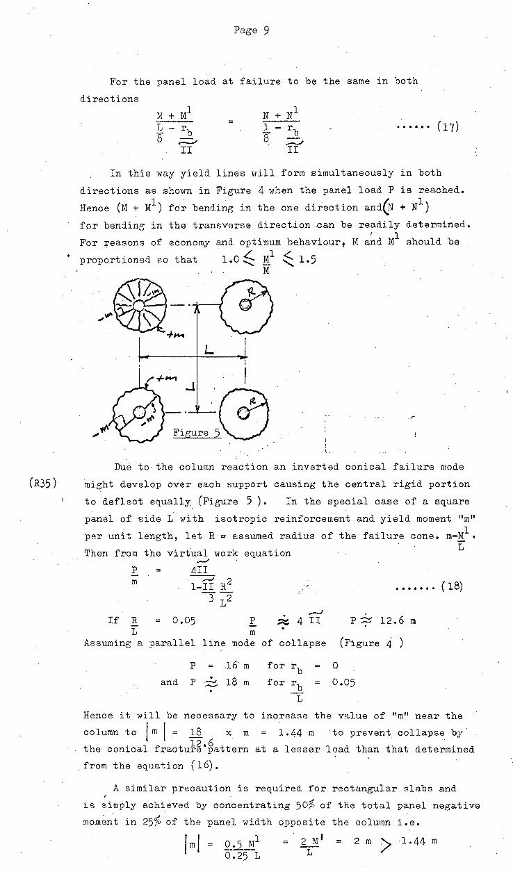
Figure 5
Due to·the column reaction an inverted conical failure mode
mieht develop over each support causing the central rigid portion
to deflect equally (Figure 5 ) • In the special case of a s~uare
panel of side 1 with isotropic reinforcement and yield moment "m" 1 per unit length, let R = assumed radius of the failure cone. m=M •
Then from the virtual work ,_./
e~uation
p
m
If R L
Assuming a
=
4II
l-IT R2
312
0.05 p m
parallel line mode
p 16m
and p • 18 m .-..J .-...;
·'·
. ---' ~ 4 II
of collapse
for rb for rb
L
1
• • • • • • • ( 18)
p~ 12.6 m
(Figu~e 4 )
0
0.05
Hence it will be necessary to increase the value of "m" near the
column to jm I= 1:_§. x m 1.44 m to prevent collapse by·
the conical fractu~~·~attern at a lesser load than that determined
from the e~uation (16).
A similar precaution is required for rectangular slabs and
is simply achieved by concentrating 50% of the total panel negative
moment in 25% of the panel width opposite the column i.e.
2 m > 1.44 m

(R38)
Page 10
As
1.0 ~ stated earlier
Ml .( - ....... 1.5.
M1 should be made )> M within the range
This concentration of steel reinforcement M
directly over the column has the additional benefit of raising
tlie punching shear strength and also reducing the deflections of
the slab. (See Elastic-Plastic behaviour).
Reference is made here to tests on an experimental model
made in America at the University of Illinois in 1959· The
slab consists of 9 square bays each 1525 x 1525 mm simply
supported along the perimeter by either shallow or rigid beams
on columns and by 4 central columns. The slab is 45 mm thick.
Details of the Model and of the cracks formed on reaching
ultimr'ite load are shown in Figures A.F2, A.F3~A.F4 in the Appendix
Two i~ealized: fracture patterns were considered and the·
ultimate load calculated for each. (Figs.~·F5, A.F6)
The experimental failure load of 1760 kg/cm2 ·w~~ f-~~d ~o be
the exact mean of the two predicted failure loads. In addition
the steel stresses were found to reach the yield values over
the entire length of the yield line.
This and other tests confirm the close agreement of the
predicted values of ultimate load using yield-line theory with.
the experimental values.
Average P test
P calc.
= 1.2.
(G) PUNCHING SHEAR STRENGTH OF SLABS
Most Codes presently determine the allowable
or ultimate punching shear at the slab-column junction
by considering the shear stress on a vertical section
around the periphery as the criterion, although failure
is actually in diagonal tension. Depending upon the Code,
the vertical section varies from the edge of the columri or
loaded area to a d.istance away equal to the effective depth
of the slab. For example :-

Page 11
A.S. No. Ca 2 - 1958 (Australian Standard)
Vs =
b2 =
d = Fe l =
L 0.022 l<'c 1 + 22 'or 100 p.s.i. maximum ......... (19)
when at least 50% of the total negative steel
and parallel to it.·
allowable shear load
Total periphery at distance
effective depth of slab
(d)
A.C.I. - 1968
v u
bl
OR
v. u
=
=
..................... •·• ••••• ( 20)
effective periphery at a distance (d/2)
from the edge of the loaded area.
•.....-:-t Vu 4l9:_ + l}/Fc1
(Hyperbolic fitting •••• (21) Equation) b d r
b = periphery at edge of loaded area r= side of square column
C.P. 114- 1967
= u w
30
The best available analysis of punching shear strength of
reinforced concrete slabs appears to be that-by MC?_~ for .E. < 3
vu = ~~~ := [15(1-0.075 r; )-5.25 Vu lp d d Vfle:J .
~(9.75-1.125 r;) r;:;}"'when Vu = l ••••••••(22) d '..../ .~.·v Vflex
Vu ultimate Shear Load
b Column perimeter or periphery of loaded area
d = Average effective depth of reinforcement
r
Vflex
For
Concrete cylinder compressive strength
Length of side of square column of equivalent area.
Ultimate flexural capacity using Yield Line
r )> 3 and for specimens with shear reinforcement the d experimental formula deduced by Tasker and Wyatt
gives
v u =
excellent results :-· .
Vu (2.5+10 )F ............ (23) bd [r/1+l · . . : .
If shear reinforcement is used r base of the outermost reinforcement. The effect of the shear reinforcement is not to support all or part of the load but to transmit the entire load
to the /
Page 1?
to the surrounding concrete so that failure can only occur
outside the shear oage.
Formula will also give good results for 1 < r
The authors recommend that the F.S. for shear should d
exceed F.S. for flexure by 0.2.
From the results of shear tests on flat slabs carried out
at the University of Illinois in 1952 and by the Portland.Cement
Association in 1954, Whitney has produced a ~traight line Empirical
formula for estimating the ultimate shear strength. Approximately
40 slabs were tested 6ft. square x 6 in. thiok.with steel ratios 1 from 0.0055 to 0.037 and with Fe from 2,000 to 5,000 p.s.i. The
slabs were loaded through the column stub and supported around their
perimeter. .All ·the important variables which greatly influence
shear strength, were taken into account e.g. steel and concrete
strength, size and spacing of bars, position of applied loading,
depth to span ,ratio and column size. The slabs were reinforced in
.two directions in which maximum shear is accompanied by maximum
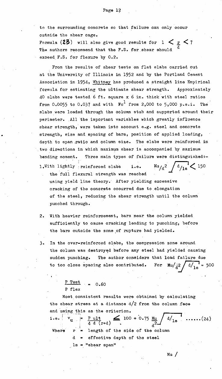
bending moment. Three main types of failure were distinguished:-
1. With lightly r reinforced slabs i.e.
the full flexural strength was reached
using yield line theory. After yielding excessive
cracking of the concrete occurred due to elongation
of the steel, reducing the shear strength until the column
punched through.
2. With heavier reinforoement, bars near the column yielded
sufficiently to cause cracking leading to punching, before
the bars outside the zone .of rupture had yielded.
3. In the over-reinforced slabs, the compression zone around
the column was destroy~d before any steel had yield.ed causing
sudden punching. The author considers that load failure due
to too close Spacing .:leo oontributed. For Mu/J~ = 500
P Test
P flex = o.6o
Most consistent results were obtained by calculating
the shear stress at a distance d/2 from the column faoe
and using this as the criterion. i
. --·l
P ult L. 100 + '0.75 Mu~ . i.e. ; v !: •••••• (24) u ! i 4 d (r+d) .. d2 I
Where r "' length of the side of the column
d = effective depth of the steel
ls "" "shear span"
Mu /
Page 13
Mu = ultimate R.M. per in. width within the base
=
=
of the
2 pd fy
pyramid of rupture ••••••••• (25)
[1-0.59 pff] when under-reinforced
fc
1vhen over-reinforced
To Pf:'eve:nt bond. failul'e, the bars should be fully anchored beyond
the point where they intersect the· pyramid of rupture. If the
bars are uniformly spaced they should not be closer than
18,000
fc 1 X bar diameter
Ttlhitney suggests that as in most cases of uniformly spaced
bars the shear capacity is less than the flexural capacity, the
best procedure would be to first calculate the total amount of
reinforcement req_uired for flexure and provide enough steel
through the pyramid of rupture to provide the same shear strength
using eq_uation (24 ). The balance of the total steel should
then be distributed outside this zone.
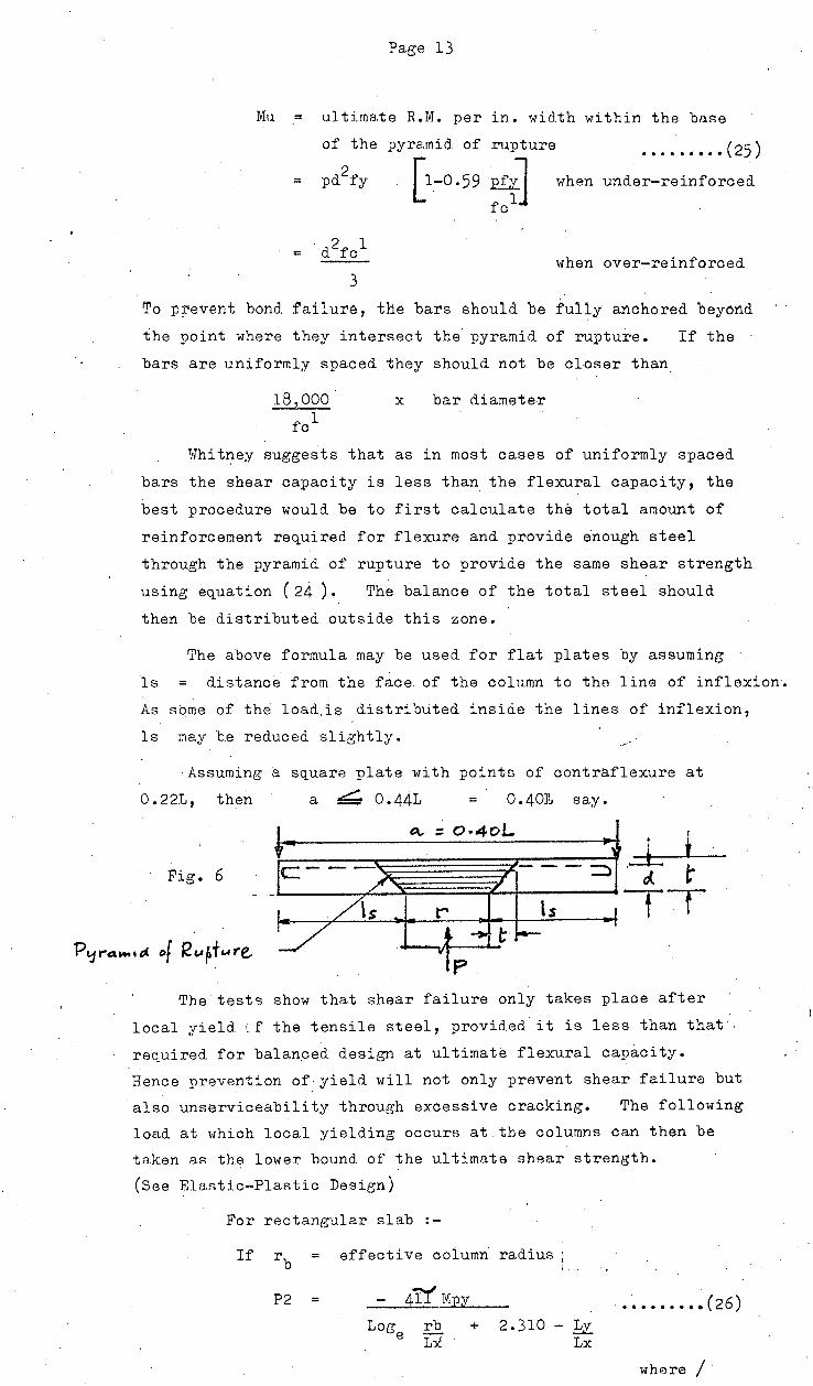
The above formula may be used for flat plates by assuming
ls distanc~ from the face of the column to the line of inflexion.
As some of the load is d.istrihtited inside the lines of inflexion,
ls may he reduced slightly.
Assuming a sq_uare plate with points of contraflexure at
0. 221, then a ~ 0.441 = 0.40r~ say.
Fig. 6
A. ::: 0·401.. . ~
c: - - :::::> /
I /is ~ r is I
~ ~ t I---~
-- v
-L t . . tJ. ~
tT p
The tests show that shear failure only takes place after
local yield ~~ f the tensile steel, provided it is less than that·
req_uired for balanced design at ultimate flexural capacity.
Hence prevention of·yield will not only prevent shear failure but
also unserviceability through excessive cracking. The following
load at which local yielding occurs at the columns can then be
taken a.R the lower bound of the ultimate shear strength.
(See Elastic-Plastic Design)
For rectangular slab :-
If effective columri radius :
P2 = Log
e rb Lx
+ 2.310 - .!:x. Lx
••••••••• ( 26)
where /

(R29)
where · M PY Ly
Lx
Page 14
= yield moment per unit width in long direction
Long span
= Short span
ELSTNER & HOGNESTAD (19.22..)_
v u = ~33 + 0.046 Fc1 in p.s.i. · • • (27)
The punching shear strength of plates is seldom a limiting
criterion however. For optimum slab performance, it will later
be shown that the slab depth is chosen so that the modulus of
rupture is not exceeded at mid-span. The resulting slab depth
normally provides adequate shear strength.
Should it be necessary however, the shear strength can be
increased by placing a structural steel shear-head over the column
and within the slab designed to take at least 75% of the full
punching shear. The length of the arms are selected so. that the
ultimate shear stress at the critical section shown which connects
the extremeties of the shear head arms,· is not exceeded at ultimate
load. Figure (7) shows a typical; detail. Tests on other
types of shear reinforcement show that the function of the shear
reinforcement is to distribute the column load to a sufficiently
large area of the adjoining slab so that shear failure can only
occur outside of it.
/ /
/ /
/
r
'\. ' /_c,_,.._l t_, _c.._ct_...;:;S;:...e.._d_·,_o_l'\_. ~1oz." c 011t.-r ·
''· l l ~I -[-_+}--J[-----'------=. -:-. ----:~1 h ' .....
T
Fie. 7
Various other authors also report excellent results by .
uRing steel grillages over the columns to transmit the column
loads safely into the slab.
(D) DEFLECTIONS I

(R37)
Pa.ge 15
(D) DEFLECTIONS OF FLAT Pl,ATES
The methods most commonly used for the analysis of Flat
Plates are ba.r->ed upon either the criterion of "allowable stress"
or the criterion of "ultimate load". This treatment is therefore '
the same as the conventional treatment of structural members.
There is increasing evidence however, that deflection should
be considered as an additional criterion, either. because it may
be associated with large strains and cracking of the concrete, or
because it may affect other parts of the structure, principally
brittle partitions. The principal difficulties to using this
criterion are however :-
1. A suitable method of calculation of the deflection
2. The rational choice of the limits of deflection.
Traditional design by "allowable stresses" of Timber structures
introduced deflection indirectly as a criterion by setting a limit
of span/360. This was supposed to prevent visible cracking of
plaster surfaces and badly sagging floors. Youngs :Modulus for
Timber under sustained loading was taken at i that for short-term
loading •. Thi~ treatment curiously resembles the present
treatment of concrete members~
In the case of·concrete structures however, which consist of
beams and slabs and panel walls bet>'l'een floor beams' inter-action
or composite action reduces stresses and deflections to a fraction
of the calculated values. In contrast, flat plate structures
behave fairly closely to the design assumptions and although
satisfactory in all respects can have deflections less than span/360
which cause severe cracking of internal partitions.
Short-Term Deflections of Slabs
The basic form of the load-deflection relationShip
is .shown in Fig ( 8 )
J[
Deflec.fton Deflec:.flon
Flat Plates
Fig. 8 (a 2_ Fig. 8(b)
In /

Page 16
In Stage I which is linear, the concrete section at mid-span
remains uncracked and the deflection is governed by the uFiual
moment-curvature relation
£y = M Ecig
•••••.•••••• ~ • ( 28)
where
d. 2
X
d2 2:...X. 2 dx
is the usual approximation for the curvature
Eo = short-term modulus for con.orete
Ig moment of inertia of the gross section neglecting the steel
T.n Sta.ge II the concrw~e has cracked. nt all crHioal Aeot:i.onB
a::> well as over large portions of its leneth, wherever M > Mer
(cracking moment). The deflection is governed ·hy th(~ following
relation at cracked sections, which neglects the ~tiffness of the
~onoret~ in tension between the cracks
M ••• • • • • • • ( 29) ------Es As d2(1-k)(l-k/
3)
where Es .modulus of elasticity of the steel
As ~ area of tensile reinforcement
k = parameter defining the depth of the neutral axis and is given by
k = j pn ( 2+pn) 1
. - pn
For lightly reinforced sections k ~ 3/8
and d2 ~Y.. = M = Ll
••••••• (30)
dx 2 0.6 Es Asd2 E·s I
where Il = 0.6 Asd2
If the average M over the beam is high e.g. simply supported
beam, equation ( 29 ) will apply over a large portion which can .
be taken as the whole beam 1vi th no serious error. Hence Stage II
will be nearly linear and the transrtion between I and II will be
brief. In other cases such as a continuous beam, equations
( 28 ) and ( 29 . ) must be applied. to the appropriate zones of
the beam and the transition will be gradual.
characterized by yield of the reinforcement.
Staee III is
However if high
shear combined. with moment at the critical section has caused bond
failure, the Gtiffner;s of that section may,be reduced to one-half
that ei.ven by equation ( 29 ) . Cent reP. of panels of flat plates shov1 the same basic pattern
of d.eflection unrl.er load. (Fig. 8(b) ) but the transition stage is
usuRlly so long that the deformations ·are quite large before the
Recond. RtR~e iR reached .• ~xperiments Rhow that cracking starts in/
Page 17
in the neighbourhood of the column head and is confined to a
fairly small roughly circular zone, having no noticeable effect
on the overall slab stiffness, especially as the reinforcement
ratio in this zone is high. Only when the modulus of rupture
i~ surpassed at the mid-span section does the slope of the curve
cbange. Cracking then spreads wjd~ly over~ ~one which ia the
most lightly reinforced in the whole slab causing a large overall
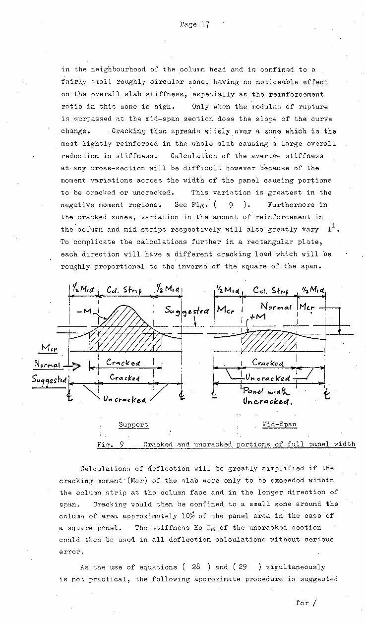
reduction in stiffness. Calculation of the average stiffness
at any cross-section 'aill be difficult ho-vHwer b·ecause of the
moment variations across the width of the panel causing portions
to be cracked ~r uncracked. This variation is greatest in the
negative moment regions. See Fig. ( 9 ) • Furthermore in
the cracked zones, variation in the amount of reinforcement in
the column and mid strips respectively will also greatly vary r 1•
To complicate the calculations further in a rectan~1lar plate,
each direction will have a different cracking load which will be
roughly proportional to the,inverse of the square of the span.
Su-ouort ____.._..._ __
'PQnef tVcdfk._
Un c..r~ cke.e;l.
Mid-Suan
Fi,q;. 9 Cracked and uncracked -oortions of full panel width
Calculations of ~eflection will be greatly simplified if the
cracking moment· (Mer) of the slab were only to be exc~eded within
the column strip at the column face and in the longer direction of
span. Crackin:'l,' would. then be confined. to a small zone around the
column of arAa approximn~ely 10% of the panel area in the case of
a square pG.nAl. The stiffneAs Eo Ig of the uncracked section
could then be used in all deflection calculationR without serious
error.
As the use of equRtions ( 28 ) and. ( 29 ) simultaneously
is not practical, the following ap~roximate procedure is suggested
for /
Page 18
for the estimation of deflections and has been found to yield'
fairly reliable results :-
1. Treat the plate as an elastic frame firstly in the one
direction carrying the full de~ign load and then the
other direction. Calculate the deflection in each case
as shown bAlow and then add both ~eflections together.
2. Calculn.te the foad. required to crack the panel j,n
th0 centre.
3. For loads < cracking load, calculate the deflection
·on the basis of·the uncracked section stiffness.
(Equation 28 ) •·
4. For loads > cr~cking load calculate the deflection
~for thA margin Of J.oad..;. above th.e craokine J.OA.d,
using th~ cracked section stiffness (Equation 29 ) or table 1 (See below).
5. For ratios of sides> 1.33 the deflection contribution
from the short span can be neglected.
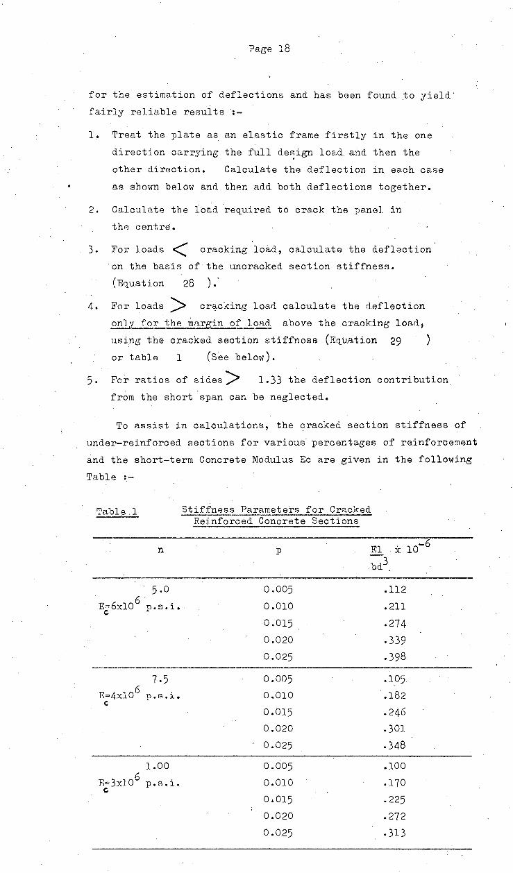
To assist in calculations, the cracked section stiffness of
under-reinforced sections for various percentages of reinforcement
and the short-term Concrete Modulus Eo are given in the following
Table :-
Table.l
n
Stiffness Parameters for Cracked Reinforced Concrete Sections
p El x bd3.
6 E== 6xl 0 p • s • i. . c
7-5 6 F::o4xl0 p. r:<. i.
'
1.00 6
B= 3xl 0 p. !?! • i. c
0.005
0.010
0.015
0.020
0.025
0.005
0.010
0.015
0.020
0.025
0.005
0.010
0.015
0.020
0.025
.112
.211
.274
.339
.398
.105
.182
.246
.301
.348
.100
.170
.225
.272
.313
10-6
Page 19
D.l. Al te:r.nati ve Method.~ of Deflection Prediction Stler,-esterl by the Writer
In its report on the defl~ction of R.C. flexural members,
( R39) A. C. I. Committee 435 recommends inter-alia the following methods
for predicting the short-term deflections :-
(R~n)
l. Bram:;on 19_63
1>/hen Mmax > Mer use the average effective stiffness
given by
Ieff - [Mer )] 3rg + E - Mer ] 3 Icr ••• (31)
Mmax Mmax
If Mmax ·< Mer use I eff = Ig
If the be~m is continuous, use the average of the I eff
. values for the positive and negative M regions •
Mer
1vhere Mer = f
1ob = Ig
cracking moment
modulus of rupture
••••••••••••••• ~(32)
second moment of area of the gross section neglecting the steel
Icr = second moment of area of cracked transformed section
Yt distance of extreme tensile fibre
Eo =
from the N.A.
33/ w3 Fo11
p.s.i. for win per ft. 3
57 ,6oop :p.s.i.
2. A.C.I. Code 1963
Use I = I
Ig when pfy ~ 500 p.s.i.
Icr when :pfy > 500 p.s.i.
If the beam is continuous use the average of the values
obtained for the positive and negative moment regions.
By applying methods (1) or (2) to. determine I eff of the
full panel width which is assumed to be conBtant over the entire
panel span, calculate the deflections ~X and .Afj in
ea.ch direction under the full load and add together for the
deflection of the panel centre.
Reference is also made to an approximate method developed
to predict deflections of floor slab systems with or without beams
based on 11 exact" or finite difference solutions for interior
rectangular panels and test data from 5 structures.
A Physical analog is proposed as a substitute for the frame/
Page 20
frame consisting of beam and plate elements delimited by the
idealized lines of contraflexure at d.istances of 0.2 L and 0.2 S
from the column lines (L = Lon~ span, S = Short span).
The beam elements have widths of 0.4 L and 0.4 S respectively
supported by columns at S centres and L centres respectively and
the plate element is the portion of slab bounded by the beam
elementR.
The total deflection at the centre of an:;internal panel
would then be the sum.of :-
(a) Deflection A~ at the centre of one of the lon~er beams
in respect to its supporting columns.
(b) Deflection ~b at the edge of the beam in respect to
its centre.
·(c) The deflection .6.c of the plate element with
respect to the edge of the beam.
~~is calculated by the elastic analysis of the beam and
Column frame (Ersatz Frame). ~b + ~ C is approximately
equal to the mid-panel deflection of a rigidly_clamped plate
of the same size and is calculated by approximate methods.
Different boundaty conditions are taken into account by. . '
calculating the rotation ~ of the panel at the boundary from
a. full panel elastic analysis, and by adjusting
fpr this rotation. This method takes into account the
restraints offered by the column stiffnesses as
fj- is then= Mcol. Col. stiffness
Measured load-deflection curves are compared with curves
obtained from the approximate method on the basis of both cracked
and uncracked sections. It was observed that short time
deflections under working load are better predicted on the basis
of uncracked sections since a large portion of the.slab is uncracked.
Furthermore slab construction under working load owes its
successful behaviour to the tensile strength of the concrete.
As there is little published evidence available that the
methods outlined above give results in reasonable agreement with
prototype flat plates, they must be ·regarded as first approximations
only. It appears more practical to restrict deflection by
ind.irect means v1hioh will be outlined hereunder.
INDIRECT CONTROL I

Page 21
D. 2. TNDT.RECT CONTROL OF DBF'LECTION
As a basis, it may be assumed for practical purposes that
gypsum plaster cracks at a strain of: 5x 10⁻⁴ and c.oncrete at a
strain of 1 x 10⁻⁴ irrespective of its strength. The cracking
strain of brickwork is believed to lie between these values and
will be estimated from tests •.
For a uniform elastic beam i'l'i th N .A. at mid-depth
M f = E &= f I y R E
1 £ = 2 Et R y h
where ~ t" = extreme fibre strain
(See Fig~ 10
N. A. --J!----1---·----- •
= v u...
h
)
h
R
Cross-Section Stress
Fig. · 10
••••• ; •••••• i •••• (33)
overall depth
Strain
Consider the case of a simply supported slab span 1 with
total load 'If uniformly distributed. (Fig. 11 )
To r al L o.-.C( 'vV )
Fig. 11
Mid-s:pan deflection \ . 5 WL~ _ 0 '- = 384 E I -
If slab is
tben
From
Et (33)
be = ~. _!_ • L L 48' R. c-
designed for no cracking at
lxl0-4 maximum
mid:-span
' -
•••••••• ( 34)
...............• ( 3 5)
i.e. Me <Mer
• and(35) fc ='s.2£~.L T. 4g T 4~ooo
de -L = ){S'oo ......••••.•• ( 3 6)

Page 22
The above deflection refers only to the immediate
elastic deflection under load. If the load is sustained for 5 years or longer, then due to creep and shrinkage which are time
I
dependant, further cracking and additional movements develop
whjch increase the deflection by an estimated 200% of its
initial value. Table ( 2 ) shows the multipliers F proposed
by th~ A.C.I. for the Long-term deflection in terms of the
initial value with a maximum value of 3. It should be noted
that by increasing the age or strength of the concr.ete at the
time of loading by curing or by delaying the application of the
load., the time dependent deflection will be reduced substantially •. -
1)t.4r~+lo.,. c4 L o~~,.,<j I Yl'jo ... th
~ mo ... .k,s
I 'je,a.r-
5 ljtt;l ($ o(' 1'\o'\OI"'e
A~ov.,r of Co""'prets•on re,~ ... forceme"'-f
A'~·O A's~o·'SAs A's ~As
I·~ t. 4 I· 3
2·0 t. g f.~
2·4 2-o f. 8
?J.o 2.. 2 ,. g
Table 2
Fo~ Lot-JG- Tf f!Vl
::Dt:Ft..ec Ttt~N.
Masonry partitions are too rigid to follow the floor
deflections and so they span from end to end possibly supporting
some- of the weight of the slabs or walls above. This will
cause severe cracking especially at openings. As only the
creep deflection of the floors influences the walls, it is
necessar,y to limit this. The American Society of Civil
Engineers limits the creep deflection to span/500 for concrete
block masonry without any information to substantiate it. On
this basis it would seem desirable to limit still further the
creep deflection of slabs carrying brick masonry.
The following criteria are therefore suggested as an ' indirect means for limiting deflection and cracking :-
· Cl. Design for no cracking at mid-span
C 2. Ratio of s~- L 32 for simple spans slab depth
These requirements will result in an initial deflection of
span/1500 and a creep deflection twice as much namely span/750
which appears to be acceptable to brick partitions.
Should req_uirement (1) above not be met the effect on the
d.eflection is illustrated in the following manner :-
In a /
Page 23
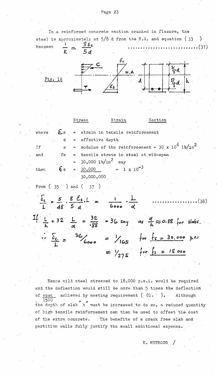
In a reinforced. concrete section cracked. in flexure, the
steel i$ approximately a.t 5/8 d. from the N .A. and equa.tion ( 33 )
becomes 1
_ $5·&<;. •••••••••••••••••••••••••••• (37)
where
If
and
then
From (
·r. . c. -L
lf L -h.
• •
R. Sd.
£.s d
s
fs
£s
_,It-
J. ... - -
Stress Strain Section
strain in tensile reinforcement
effective depth
l
\ct 9gd h.
modulus of the reinforcement = 30 x 106 lb/in2
tensile stress in steel at mid-span
30,000 lb/in2 say
30 ,ooo = 30 '000 '000 .
35 ) and ( 3 7 )
s 8 cs .L L .................. ( 38) =' =- ·--. 4g 5 G( bOC>O c(
r::. 32' L 32 ~ 3~ So1 ct t~>r slab'. ::; - t::\S h~o.88 ·88 0(.
~c, 3~ - Y,~s for ts- :;:. 31>, 000 P·''' - -- - boo o L - .Y27s
fpr fs - 18' oo C> - -
Hence mild steel stressed to.l8,000 p.s.i. would be required
and the deflection would still be more than 5 ti~es the deflection
· of span achieved. by meeting requirement ( Cl ~ ) . Although ·'· 1500 l' II
the depth of slab h must be increased to do so, a reduced quantity
of high tensile reinforcement can then be used to offset the cost
of the extra concrete. The benefits of a crack free slab and
partJ.tion walls fully justify the small additional expense.
E. METHODS I

Page 24
E. M~THODS OF DESIGN OF FLAT PLATES
E.l. ELASTIC METHOD
Design by the above method may be carried out either in
accordance with the American Concrete Institute (A.C.I.) Building
Co<le 318~63 sections 2101 - 2104,. or the British Standard. Code of
Practice C.P. 114 Clauses 325 - 332. Both methods are essentially
the same with small variations which will be described. It is
expected that the European Codes are also similar in their methods.
The follovting assumptions are made and all .sections are
proportioned for the moments and shears so obtained.
l. The structure may be considered to be divided longitudinally
and transversely into frames consisting of a row of columns and
strips of supported slabs with a width eq_ual to the distance
between the centre lines of the panels on either side of the
columns.
2. Each frame may be analysed in its entirety or each floor or
roof may be analysed separately with the columns above or below
fixed at thei.r extremeties. Any sui table method of analysis may
be used e.g. Moment Distribution.
3. The spans used in the analysis should be the ·distances between
centres of supports. For the purpose of determining the relative
stiffness of the members the moment of inertia of any section of
slab or column shall be taken as the gross section of concrete
alone. Any variation in the moment of inertia along the axes
of the slabs and columns should be taken into account. (In flat
plates there is no variation). Joints between columns and
slab are to be considered rigid (infinite moment of inertia).
4· The maximum bending moments near mid-span of a panel and at
the centre line of the supports should be calculated for th.e
following arrangements of the full imposed loads :-
(i) Alternate spans loaded and all other spans unloaded
(ii) Any two adjacent spans loaded and the other unloaded
The above req_uirements are from C.P. 114. A. C. I. 318-63
as8umes that the maximum bending moments at the critical sections
occur und.er t full live loads,· as conditions (i) and (ii) cannot
occur simultaneously and hence some redis~ribution of moment is
possible. However the design moments taken must not be less
tha.n those occuring with full live load on all panels.
s. I
Page 25
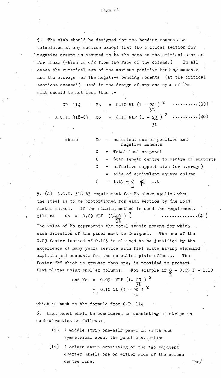
5. The slab should be designed for the bend.ine moments so
calculated at any section except that the critical section for
negative moment is assumed to be the same as the.critical section
for shear ( wh.ich is d/2 from the face of the column.) In all
cases the numerical sum of the maximum positive bending moments
and the average of the negative bending moments (at the critical
sections assumed) used in t~e design of· any one span of the
slab should be not less than :-
CP 114 Mo = 0.10 WL (1 - 20 ) 2
31 •••••••••• ( 39)
A.C.I. 318-63 Mo 0.10 WLF (1 - 20 ) 2
31
••••.••••• ( 40)
where Mo = numerical sum of positive and negative moments
\·T = rrotal load on panel
L = Span length centre to centre of supports
c = effective support size (or average)
= side of equivalent square column
F 1.15 - C f 1. 0 L
5. (~) A.C.I. 318-63 requirement for Mo above applies when
the steel is to be proportioned for each se~tion by the Load
factor method. If the elastic method is used the requirement
will be Mo = 0.09 TrTLF (1~_2C) 2 •••••••••••••• (41) 31
The value of Mo represents the total static moment for which
each direction of the panel must be designed. The 1..}.se of the
0.09 factor instead of 0.125 is claimed td be justified bf. the
experience of many years service with flat slabs having standard
oapi tals and. accounts for the. so-called plate effects. The
factor "F" which is greater than one,'is provided to protect
flat plates using smaller columns. For example if C = 0.05 F = 1.10
and Mo 0.09· W1F (1- ~ ) 2
31 0 • 1 0 HL ( 1 - .?.Q. ) 2
31
which is back to the formula from C.P. 114
.L
6. Each panel shall be considered as consisting of strips in
each direction as follows:-
(i) A middle strip one-half panel in width and
symmetrical about the panel centre-line
(ii) A column strip consisting of the two adjacent
quarter panels one on either side of the column
centre line. The/

oc
*-
Page 26
'I1he bend.ing moments 1-1hich have been. calculated for the full panel
11idth at the ori tical c>ections 8houlrl be divided betw8cn the
oolnmn anrl mid-strips as follows:-
C'P .114 '118.ble 21 Co1umn Stri12 Middle
A.C.I. 318-63 Table 219.L(.9l CP114 ACI CP114
Negative moments at internal support 75 76 25
Positive II 55 60 45
Negative II at external support 75 80 25
StriT
ACI
24
40
20
These percentages may be varied by 10% provided the total is the same •.
Distribution of bending moments between Column and Mid. Strips in
percent of the total moment at the critical sections
7. The shear on vertical sections following a periphery b1 at
a distance d/2 from the face of the column shall be computed and
limited as follows :-
CP 114 . • • v '= s 40 ~ 130 p.£., ..• (42) ' .
ACI 318"-63 : v u
• • • • • • • • • • • • • ( 43)
Uw cube strength = cylinder strength
8. Bars should be spaced uniformly across each panel strip in
both directions except
CP 114 - 50% of the total panel negative moment steel should
be uniformly spaced across the middle so% of the
column strip
ACI 318-63 At least 25% of the total negative reinforcement
in the column strip C: 20% of total steel in panel)
should cross a periphery located at a distance d
from the column. Spacing of bars·= Zh maximum

Page 27
1 ' I
~r.,~~t~]) rstrt\1t.., rr--o""'" > ~
~ ~
\ .
II 4-
'1-,)'-ft d. I""'
K ,., '4 i. g L o/4 f-+<..+M 1 '1 ,
CtJ. S+r•(l 'I~ Lj~ "f Y4-. 1~
CP 114 ACI 318-63
Stepped Distribution of Reinforcement at
Critical Negative Moment Section c = column width d = ·.slab effective depth
9. 'Total thickness of the slab shall not be less than
CP 114 ~ 5 tf \
ACI 318-63 . 5" • \
(Elastic)
A.C.I. (Load Factor
f _L_ 40,000
50,000
60,000
L 32
1 36
for end panels 1 . ) 36
or 0.0281 (l-2c) 31
for internal panels
+ 1-~tl
Fc1
design) Table 2101 (e)
minimum slab thickness
L/36 )
L/33 ) or 5" )
L/30 )
10. Maximum Bending Moments in Columns shall be determined from
the condition of full live load on one adjacent panel and the
other adjacent panel unloaded.
11. In the case of flat plates designed by the TSJ.astic Method.
which fall within the limitations req_uired by the Empirical
.Methoc1 (::;ee section E2) the A.C.I. code permits the resnlting
an8.lyti.cal moments to be reduced by a constant proportion. so
· that the value of Mo is the same as that permitted in the
F.mpirical Method. If this is done, it amounts to a redistri
bution of the moments obtained by the Empirical Method,from the
critical negative moment section to the critical positive moment
section,necessitating slightly more reinforcement.
Under these circumstances it·would be more feasible to /

Paee 28
to design by the Empirical Method in all cases where the
limitations are ~atisfied. The value of this dispensation
is therefore queried. No similar.dispensation is made in CP.ll4
E.2. EMPIRICAL METHOD
Design Bending Moments are given at the critical sections
which are ,justified by the behaviour and ultimate capacity of
similar tested. structures. They apply one when the following
limitations are satisfied :-
l. The construction shall consist of at least 3 continuotis
panels in each direction.
2. The ratio of length to width of any panel is not greater
than 1.33
3. The grid pattern shall be approximately rectangular.
Successive span lengths in any direction shall not differ
by more than. in CP.ll4 - 10% and in A.C.I. - 20%
of the longer span. End spans to be equal or less
than interior spans. In the A.C.I.,~columns may be
also offset a maximum of 10% of the span in direction
of the offset.
4. Critical sections for the bending moments are given
as follows :-
(i) Positive moment along the centre lines of ~he panel
( ii) Negat·i ve moment along the line adjacent and parallel
to the column centre line and a distance of d/2
from the column face.
5. Numerical sums of positive and negative moments (Mo) ·
is given by
CP.ll4 Mo = 0.10 WL (l-2c ) 2
31
ACI : Mo 0.10 WLF (l-2c) 2 for Load-factor 31 ·; design of sections
0.09 1-TLF (l-2c )2 for Elastic design 31 of sections
6. Distribution of B~M. between Column and Mid-strip as
percentages of Mo are given below· in plan.form by
ACI - Section 2104

•I '-! ·' .f ~ ~-~ ~ ~· .:t-v
~~ ~ ~~ ' 4 ~
~ ~ ~ ~ ~ 1...
~~
Page 29
In T£/ftP,e IN 7 ~,e ID,e ;rr /,vr,!=,fto,e E~r~,e.,6,e ~~ 7,C:~I'D,('
Svf'P o,e r CI!NrR~ ..!'v)'}'~,e r ~~,vrR~ .r v .,i),l'~,e.,.
f ] I_ .. l L
--23 +II - zs (-zi) +14 -20
-16 riG· -/t? f-tc) r2o -10
:
D 0 r t-ZZ. .f Zi -
.. ~
~46 -so {-- 4bj -/10
Fig. 14 Design Moment Diagram
Distribution given by CP 114 is identical to the above
except for the ~ercentages given ·in brackets.
O•'Z.L
Fig. 15_ Arranp.:ement of Bars in Column and Mid Strips
7./

Page 30
B. M. in Columns
CP 114 : Internal Columns M 50% of Negative M in Column c
::: 23% Mo
E:xternal Columns M = 90% of Negative M in Colurim c
37% Mo
ACI 318-63;Columns to be proportioned for B.M. developed
by ineq_ual loading on panels or uneven
column spacing so that
Strip
Strip
!vic = ••••••••••••••• (44)
f = 30 for External Columns
= 40 for Internal Columns
In both Codes, Me is. to be divided between the upper and
lower column in proportion to their stiffnesses.
8. Minimum thicknesses of slab are specified in the
same way as the Elastic Method.
9. Shear on the critical sections is limited in the
same way as· in the Elastic Method.
Page 31
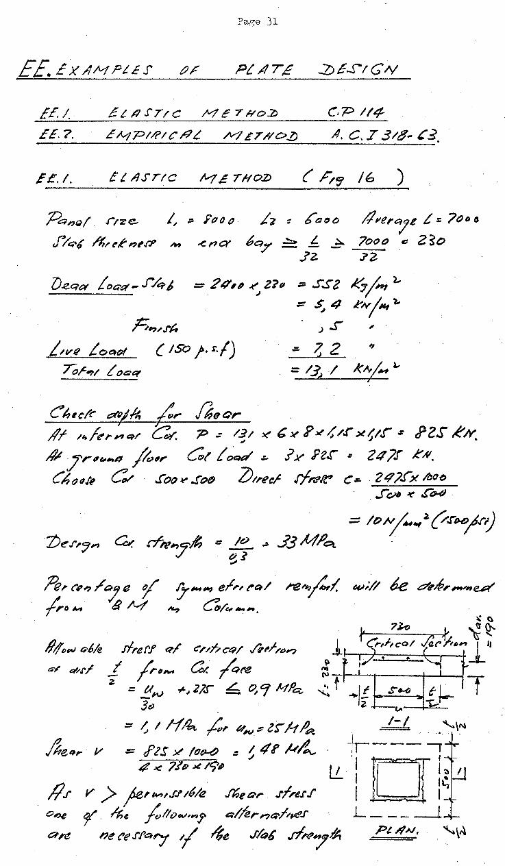
EE. Ex AMPt.e.r
EE.J. £ L /i S"Ttc M c 7 Ho:/) c.p 114
_E_E~. _?_. __ E_N;_.:._P_I/?_I_C_/?_L __ /V1_..::.£...:...T...:....:#_o_z;=-_-A_.:.....C:::....:...:. • .7=-=3~/...::'8-_--_:,:..=~·
f£.1. f L IJSTIC lv1 £ 'THOZJ ( //'! /6 )
.f'l ~ 6t:J(J()
6qy .:::: 1:. ~ .lZ.
/l"'e~'7.t t = ?~or, ?ooo C' 2~0 7'2-
;=;,~.rt,
:: 2 q,, ~ 2?tJ ;:; SS2 ~ ~~ 4.
~ ~ 4 I:"N/~~t ,_
) S' ,
&vii fot:fof (ISO i· $./) .:;, 7 2 .J .
Ch1cl~ dUj/1, ,;:,.. IJeQr ~ J
/If ,,/t',.#"'q/ ~ 7-> .: ~~~ ><' & )(' P~;; 1.r x11r z RZS RN. .4t /r'~ .. n fo(l,. c;l! ~ ~ Jy FZl"' ~ 24?1' KAI.
ChtJ~It ~ ..f"o~~ .!"otJ ZJ1recr .r/I'IJ'.fr C~~o 24?.Jx lbo~ . f~ ~ ~tU)
·. . =: /ON~_,~(/r~J.D;.r;)
·ZJf!'.r~'7~ &. rr-,7;~, e .!!!... ~ 33 M!?ct. · ~1
~ .. ()o.,./~a 1 7""'"" e/,.,r-./ ~-e~l. ..-;// k ~_,p,,_,e.A' (,oM !i M ~ ~/c:.-4h,,
#1/t;w q,6_k lfref'.f q/ e'/',nct:~/ -""r"~~? ~ t:PI'/ _t /r~~~ c«. ~re
z. = UN +JZl.J ~ ~Cf Ml'c;,_ -3f)
:: 0 I /fA,._ ;:,,. UN$ ZS" H jJ~
/},eq,. v = /'lS .Y /tJ~ .:: ~ 41' k~ # .1<: 7./P .>e /9'
~
"" (\) T~--''--t---+---L.---1 •• I ~
I -~~---,
u_ I f[ :IJ' !~ !J I . .. I L ___ ____J
V > je~ ,.,.,, J..! 1~/.e f6e Qr J/,er J'
9f". /;;e ~l!vt/1/,.,~ Q//er ,-,e;-;/,vt'.l'
net'e.r~a7 'l ~e J/~6 d#7#.

Page 32
' ;
~===:=::::=::::;::;======~;==:::======++ -:r ~ ~ Ty}d"'-' r/m-
. :'[~·.. t. I.' ~ z -t""f •.. 0 .
';;-;- w
1:*===:::::::::====::±=::=====!=:::::::=======~ ~L--,:---
.. ; 1-i

Page 33
1.1' ntJ/ ~'l?artta.rect .-/. hcl'~r;.re .r/ot
~""" 1/ ~ fh, .-K"*.rr f2- /c, 3J'o "'- ~,.,.,1h,,f
/6 6 X' 41' X ~I~ J(/OOD ::: () 9/ N~ J
4 ~ J'?o Jt (?tfo·..r(}}
C~ .//2€1 ~. 9.JD K i:J.rtJ 2. L;,c,.~ li'.l'~ -"e. ~t~~ ~ J:. (J'z.r- /J) /tJ~ ~ · = ~ 9/ N/~
~ ><! //1': ~ ICJ~.
1. 'Prt~(n&Ye ~eq,. '<?~/&''~ ~H/',,e ~9. /k.tP/ ;r;tl'~ ·
4'. Znc-,,Q~ 4t. . .1/t?l /h,cK-ne/.1 ~.1')5 ~P-'' life ~n ~ a .r/q-6 at~>~· 3J-o .... .)(' i'f:)(/~ ~ 2()o tJ
~d h/) ~~~, cl1a7e..r :!he Cru'>.drtJ# d,.~, 4 __ _ ., / letr .f'/e:~J h Q;,llf /.f n~l Ct>n.r,.q.?,.,q he~ •
.r. a ('r;,._, /;,, QfnP,.· r 0 2 ~PI" 3.
Jo kf,.~ : hcN'fl.!e' ,n;e .lfol ~~.f n'.r/ fo f' 2.!"'() ~-Q,.Iilf j re' VI'~ q .rfN~I .l'h6't:>i-- ~I'Qtf e>~r
~~ ~t ( Ft:~ 17 ) .
..
;fe~N-~ ?J,Qq Lo~ .- ~ 4 K~ l Lt~ I#Q&; J:. ~ 2 I ~ -
. /of4/ /J b "' . J
-= /;t' ~ #I'~ lt.f "- = J' G .r R AI. ~ J
Z "" /.5'~,; .vJ.!" L 114/~C( l<:i~r ;4 Jont ~~,.. IJt.r,l'/t;,.f'e r:: 4 '< /rPx 1.:1~ Cj..l
: J2.! K ...v t:::;; J>'o% p '""'
.7/ -h7~ 4 r. /heor htiQp/ I 2 0~ ./;;eo,. .rh~r,. "'" cr, /; ro / jer'/6.> 7 : -
t/.; u~~- t) ~"~ :::: ~l6 H/et_ · 4 .v J(jt>~ Jt' "Jo;J v 2o t>J < 0.) 9 ~/"'-' .
Pe,'l/,(7 /gy c;..,;,.("Q/ ./le&-r
.,r:;,_ I 7
>

Page 34
{~1 IC )
ne. /()!/,...;,,, /~t:;-oflnJ Qrre:fnlem enf.J Qr£
I. L c J4~ k.1.1
("') f Zl.~ • 7o}KA/ f ... J . t '.1•7
A B c
L.~:: 34.S
13
/-",,. H,.Jt ~ ~ c:n' t?j 8 c/.Z>
(c) ~k=="~:;=:?:;.J.f,~~==~ti==~::;:.=~=J=ttt.r==Jf:===1=t>=7===t..1- ,e., ~..r $.1'f ~ ~ c
.Z.rlt:('6
(~n c,.eutvPI)
.Tc.t (t4 r;~:u·kP()
7) /.Jf,,o~ It#~
c I,
f!t~,_efne&l'/ ?),-.rfr~~.,-/tP, f;rJ (6)
/lJy._._ef,.lrar~ J)~.rr,~I-1'/DM
(c)
hx ..ec.r .6,pt ~Alii' 'I H
lJeqtt t t:Ja « M -==
f,~ L oet« M ..: .?oJ x ~-z..
.l4r J( ~'
. ·.. ~····. ' '
D
-r
e co.) k--V, ~
z. Z]o k...u. ~

Page 35
C? !y;~(Q/ C q /t:r;, /af" Pn will 6e C,Qrr ~'Cl oc.~f /Pr ·(b) L J.9
(:fJ @® <i~ " 6S'2k AJ
(JA B' )4zt Z).~ ~zo~ -rz.o.r --z~s- 1.: fM
L.t. -2]t:J +llQ 0 34--o -!Jl.&
I ,... I~
f 117 -2i -- J".l /16 K~l.~:J >< '-.!"'9 - ze 0 MA/8 _. /.9Jt' 3·16 x_1~ + K' >< - ltJ!! - 7
- 7 "' 4 <:> ~4-o
.,t 2 - I 0 - 2 7? £». ,._ -..tD-
-]4o ~.t;fl~ - 24() . Gtt"4t/ MA.8 _. ]4p- ]I~ Jtfii/J ~ J
~ ...-- C(,/, 1'-f""''"ff ~ > 222 !<AI.~ 'l 0'--
'---""0> I ~
@ (E) ~ @@ 0 -ze~r ~ZCJs" -z.or "''"r -~C>.i' ~z.or
-21D ~l.~~ -z.Jo -1-Uo 0 Q
'l-117 ~ 0 - ~7 - 47 - ss-0 >< +ftJ -Z4 >< 0 -z? ~ .. z4 0 ><:.. ~7 - ·7 ><.;6 ~6 ~~7
-4 0 -rJ -4 ~4 ~.s +I -I -I e:J C) -/
-)Z./ .,t. 4!'6 -4t/f -119~ -Z7o ~ 14~
A c
Zl. ..J.£ - zgs- ~zr;.r ~2t>.r
~t -2$0
a,-,d fp; (&t) · . 6.!2 ~~·
4-o c....,~J ~6 L :/'.,.. .M t? 4n>
..;.s;r >< .rS.) ~ za ~ zJ> ~li C>
- tP >< - 7 - 3 - 3 -4 (:>
l'v113/C o:- .?Zb Jt4~J2- 4/o
:::. 242 RAJ ,.;., . ..; I ~I ()
/)2.. .,t.J?f -411>
Ju( t L~f,_ * )41.r Jz6 ·I
r'ZtJ -II -Z22. 346
MaA -:;. ¢f.r- , .l4~~~1lJ'
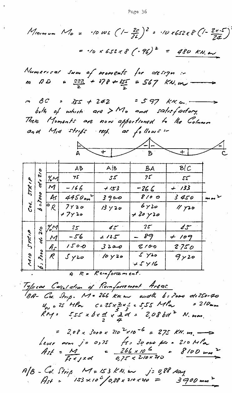
Page 36
•!o W! { /- .!.£) z ~ •lo .rC.rz .( f' (i- ~s-) ~ ~t z~/
::: ·/o J(' 6.rt < J> {· r~ 2. =- "'~o k.AJ. ~
~H14 ,.; rq./ J'#lf'~ 'l P,r;~e,/J- ~,. 0/e .1'1'71'1 .. ,.
M /) /) g. .£~ii ~ '71 r~-1!:[ ;:. St 7 ,t"'AJ. ~ ... 2. ~
=- ,f.rs -1- 242. = ..> 97 k..-v. 4-. ---~>
t// w/J,e-/J · ~1'9 > /V7 o e>~u?f .f'Q~./'/~cl'ol"-f. lfo,.,4~f..r ~>,-e hD w . ?jo,. fin11'PI ,t; ,4', C:/..,""',., l--1,4 .rf,.;/.r · rt>-JI. 41" j. II• w .r 1
-
~ ~ ~ A ~ · e· ~~ :;?' ~
~ A? A/5 .BA 'B{C '
~ t\) %M 7! sr 7!" SA " ... '()
~ M -lt6 -1- IS'S -2b( -1- /JJ ~
A! 445' () lllrt '&; F /tJ o 5 4£"() ~
5 'f!;-0 ~ ~· QR.. 6 y ].C) ~
,, 7'1-z.o 13 y '2.~ // y~o ~
~ 7y l.o ..; 21) yao
~ %.1'1 cr ttr · 2S"' ".r ~ ~
-s-6 ~~ + toe; 't ~ M .,t. ll. s- -/S'O..() c. ll.r .J 2. 01-0 -e /8--Q Z}.ro
~
~ ~
lie .I '(~c> · 1~ y2o .( Y•o 7 yZo ~ ( ., ·~ jy/' ~
~ le .. R e'"'/"""ee.-, e"' I.
' ¥-''""" C' ..... .,../ ... 1?- ¥' £,~*''""'"'~ ,/,~qJ"; ' $/l- C:, JJ.,~. ~ • 2b6 RN. ,__, IU/a'~ I.: .?ot#-tJ c/.r ?.!'"P#' ¢<J
tl. t:- ?S ft-tflA; c::. Z.l ~ :!:x.!. c .j s.r Nl',., .:; 2/P-.._. ~ 3 $ ~
£ J'.-4 3 .r .r .J X b >t ::{ l( ..J... I?( .:. 2 () J' J t:( ~ N. It-t~ . I ~ z 9- ,
::: 2,P! ~ .!(>"~ Jt' 'liP""~/()_, :;:. Z7J" A"'N. ,.,.
lev-~, ,,./IV) /. ~ 0) ?J' fr J Jq .,.,.,., ~ ... z /l> .,.t( r'""-#.t! :: M c. 26{, x IP ~ ~ J> IP () ,_.., ,_.
fr l( .1 ~ o< q, 1.r J( ~/() x zt v >
~/13- Ct. J;,.~ ~::- /~J eAJ. ~ ;; ~??A~ , IJ.r-1 :. IS3 =><It? /(',I'R K 2.1'~ ~"lltJ ;:::.:. .3 CftJtJ ,.,., )..
Page 37
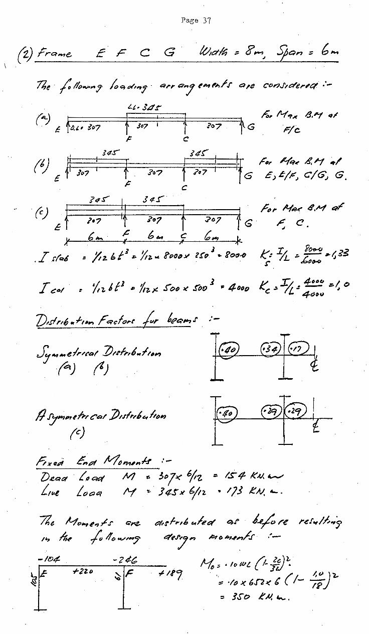
c F C G
t c
(t) £ fl !¢S"" i4~
1t6 i f. f Jo7 .?o? ?(/7
~ c ?t~s"'
~ s"r
(c) J f tG .?•? ~07 :;>o?
.& b ..... 6., c c,., ,r 'I! 't ~
" " ,.-. z .!'1'~6. :: /t f 1 Yt t J . z. I> /Po 1-z.""' ~(J/)JI' trfJ .. E'or1~
/l 7"""' f;./ Ca/ :/),J'fi',J e, h~;~ (c)
n )f et?i E,p~ ~""'"k :-
;:;, 1'-(.,..lt /).~ .~
r-;c.
/'t~, lt-(q.., ~ ~ #1/
£) &/P:J C/G'; G.
r",. N~..r- d.M ~ r: c
"'
k': ~ ~ 1~ ·~$$ r (;~
lJ.e.Qt:l . ftJcut M ~ 3"7J( o/tz ~ IS£! KM "-"
f.,t~.t Loa&JI /Lf ~. J 4.!' X ¥2. .. 173 eN. ,_.
7le H c>-, ~ <? ~ .r t::l"'$,.
'" n~ ;. ,.,f> .,.,~,. t7krf,..,6 c.lee:t e;~ · 1_,/u re r~t.,/fi.,'s
e:l'tt/ M ~ b .,.,~/..r. •'-
Page 38
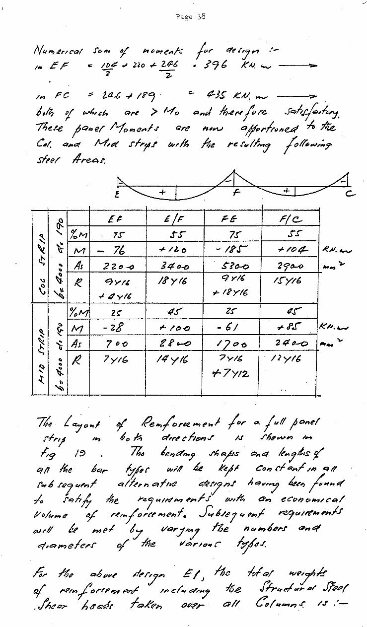
N""'~NC'Q/ .r(;f,. ,r l>ttJ,.,~~~.r 110 ff r oe: It;¢ ~ Uo ~ Z..IJ-6
-'f* ~
fr eft'I''J"" .'-
• .I C) t K .V. "-' __ ...... ,.._
In r c :; 2.4..6 .., li'j ' ::... ¢--JS' K~ ~ ,..
1,1~ 'f w~,&h a,-, > lvfo ~,.,J ~..er-' fr.e, .J'Qt.r.f,l~. %e.r..e fQ"e/ 1'-fo~e,fJ t:~re ~'~"~ t:::~~rft~,u~ ~ .7'4 • C~~t. a,.~ ~vt rf,f!l.r ec,,.A; /:;e re .r~//;7 r~,.,,.:.,. sf~e/ lf.reo,~.
~ E# £/F FE- r(e-
~ ' %fv7 '?S'" s-r 7!" _t-,r'
~ ~ /V1 - 7l, + /J..o -lf'r + /t:>¢.
c.; ' lis 22(')-() ] 4 fJ-() . ~?~ 2<j'tJ-O '
\l ~ I< t:?'YI.& /l'y/6 C/YI.& t.r-y/6 ~ ~ .,J 4 yl' r IIY/6
%tv1 2~ 4.!" Z!" tl.!' ';)
/Vf -2! ,_ I 1:1 -o - b/ ~ I'.J ~ ~ ~ ~ As 7D(') £ tf o-e> /Jo-o 24~-o c.;
~ I< 7yt& 14yl' "?y/,& /2yl6 ~ ' ~ r7YI2--t u ~ I •
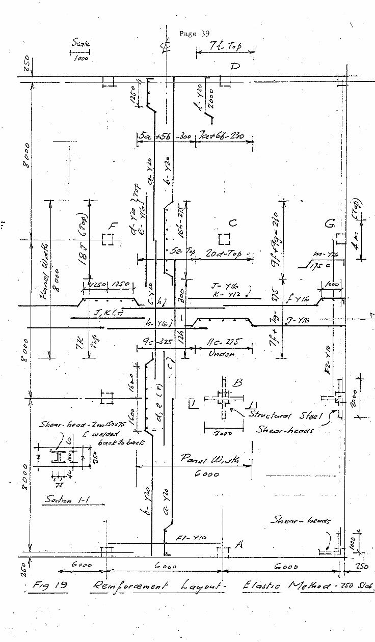
lk f ~o~! ¥' Pe~{oree 141tl'kf /or ~ jull ;a,e/ r.fr'l ,,., I 1:> A? e:;~,.,., eo hDI'IJ' /J .r6'vV"' ,.~
~9 /~ n: /e,dt .. J' ./"hrs' o,.(}"/ k,Jts ~ q/1 Re 6&1,.. &f"r e11ltf 6 R-ef" CD, rf ~/ ~~ t::~,? J'.,b .r"'J .,,,f .. ;J,,., e:,lt..e ~"J'n.l A .. w/ ~ ...... ;:H .. -r' ~ f'e,h6 16e r.c.Jt-tll'd'~ ~;..,t.r p...,~ a~ eCC~I?c:>lf.-11~~1
1/t;/e,~t? ¥ r~, .. /o,.t'l'hJel1f. ~b./t'J et p.,f ~9"1~~~tt,;,J.f w,l/ "' ~ne~ 7 1/Q"'./'7 ne i'/e,~,.q~.f ~,q q,aMe/e,-.r aj" /1Je Veu·n,.,.r ¥.1,
/i,. ~.. Rb ""' P.-r:J" . E I J i-h<~ o/ '""""/orr.? '14 P~ 1,., etc, ~,.7 1/;.e . A~t:t?- /;oa4r foRt?;, t/1)?;- · t::P//
lofq/ ~~:r~.t Jl.rq~vr A'/ Jfi,p{
~~~ .. , .( /.1' .·-
.
~~ ~~
~-
Seqre ~
(()OO
I I i . I )
- ....... -1---
·~
~ (;
I I t--l-
' .
-
F ''}--: -f---1-- .. --1---!-L •:-1~
~
. '
l
W{ 7S
S'::>cfl"t)n I~ I ___..
l btJpo
. I \ Paf'ie 39
. ~t r 7/.. r., 1 D I ... _ r- '""' I I . --
tl <:) '--1
~ "" c . >.. ()
' '\. ~
-~ ...... "' lb<=t- -/$6 -lt>o 1 k-rCj .... :23-o 1 ~ l l
a a ~ ~ >-..
I I
(~ c- ~
l
rv....... -t-
·~ • ~~ ~~ C\j
• ' c 't!~ • ~ .,
• "' LJ I
•5e- b:;} Zod~?O;o .. :. 1 I
I I
"-, -.-1 () .T- Y!k:> ) ~ __ ...:K...;;._-_Y;..;,I_2-=--
-r '+ I ! .
·. !
i I I
I I ! I
I I I l
' -t.- ..
G ' I
r-1--
#-?- y, ~ tJ.t'" o I
l./o~
1 I )" -.. f1
' :h~ y 16) l ~- • ~ .. "'--i'--.~~,7~·-_>1_~ __ 1---1
'\.
~ )..
II c .. ZJ.) r t:0 Vnd"""· l
~ ~ ~ ):.,
~ \!
,c /- y l't'>
r~-r A 1 I· I
..... ,_ ...... ,
·~ t\: \.,_ ~-·
~ ~
..J f-
-
t;;oot> l~D
t--
.
~ -;or Re/nj_t?r_ce_~_~?_e_,_r __ L_q~o/~u-~_.f_- E /q.r/,/c Me&" a' - ?rv J:/~.
H~ No l};r::t
C\ 24 yzo 6 22 yzo c 2o y~
cl 4 'f2C e IO Yt6
;, 12. Y/6
' J2. YIG
h 17 y/6
:r ]( yt{,
K 1¢ ytl-
t 1.¢ yzo m f YIG
;:, 2.0 Yto
/2- ./6 yto
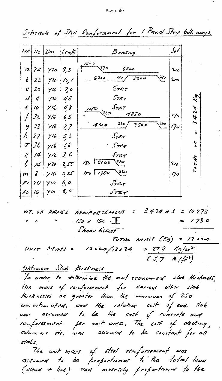
?age 40
t.~~ 8~na''"J fel 1.!"~ IJ
?.,S I \(7o •
b btl-() 7..1'(1
/C) I ~Zoe> 2}c>~ 'l.,;o
"" 7o s-r~r "' '
4<f S'ntr " 4i /1.1"0 . S'~r I
6S ~ 41'f"o tJo "' ~1 46Do Z.~r>~ IJo
$3 J17!T I
J6 J~ " .t' J~
z.r~ l.!"o r t~oo ~~ tl'()
" 2l!' l,ro I 17So.., ~~ IJo
6 0 . ./ J~ K,o , J~
/l~w~ fl~ c~ ~--t£1f/T
. /.f'~ Ji' ISO ][
fhe.a;.·. A~~-,--···
34-2.11~1 :::.. /()27Z
.:;::. I 7.$ 0
'nJ r ~ N?~~?.t .t t' K,) s:s I z IJ o -e
/2eJ~/tJ!24 ~ Z~R ..<"':;(...,)., ( .r: 7 16(/Jj
o;h,_,~_, Jl~ ~,.-ci'ne.t.l' I :/,., ora',;- f'q c::faf4r~ ,.j,.e Ide #IN! e&-tJnqnu t-q( .r/a-6 a4~~~J'f
J
ln.e n~t:~.a '( ,e,~;-~,,,,f ~,. vo,.'(Jqt tJit,,,.. · .r/Q6
kt&K ,erl'~.f all JriiRfP; /hQ,., /he JM,,,4#..,~ r 2S"o
we,~ e.rf,-. ~I ee:f}l a~~# /6e re(e;-bve c().rf- i eo~ .r/~6 W&'lf qJ'./'c,,.,ft.t::f lo ~ /~e Ct?.rl- y t:Pn~r4'M e::;o,t:(
,.a,,~r~e~e,f ;..er """''r art'&~. 7he c,J',& ~ der~'"'7J cct4'~ , L' elt'. ev ~:u 4J'.r~P~f?et 1~ ~ c",.rfo,.f- ;;,. Ql/
. .J(Qbf,
ne. un;f k-}t:;.f'.f
k q.rJ~:~~efl/ I" {otead + 4v.e.)
tj' .rff1.,f l'~li?fr~tP#'Ji'hf w~.r prej~~";l,..~>h Q/ ~ /he /e,IQI
CP""q /1? 1/~r.i~/j j r1 orltt~n 41' fo

Page 41
.ej/e cltva, di lh o( ~e re,~jCJrce ~ e~l dtr, rft" p, •
i/.r.t"it-?e4 Vn,f f'qfer
. Co,., crelt ~~ Sicr6 (l.S' Ntlct}
Sftet f'e,,(e>r~ 44ft'nf &:0 Rt.ro ;uH?ef..r, ~ h,
. .e If I&, ~o je,. ntef,., 1
~ /( ~ z.r r ~,.
>
flte/ M.-1&/.ff "' IJ]tJ~Ztv -1- l()l/DJ(!,!_ei 1/ !!J_4;:. t::f,7~t; tt7. '2epP . 2-~" I~ b 2Z ., h _/ -a.
1l,,e ";"
. c:= "'~ 1{~,., ~
t/ Ate. /ha,e~, _. h4t:i&fl aM t4Kr.,,-/!.d ,_, n.,ve,./11
/~'"/fl,. ;,~', :h> /$'B ,~ t>ftue 4~ J, ¥ 4t~ .r!R6
.,f.;, lfhl '") .
0
-:::. If t''J/IM"" >-
~ l{,j~ ' A/o J"heQr /'e,,.;fJ~et ~'"' f IS re t:jr..tr~t:JI.
St;r1$ .. f '2 s t) lo() 33o 3Lo -# 380 R.~l.e. Ill CCJn&l'ek 4, 0 () 4 ?o S, Jo !'"(o G.,.·to f tbj,.,].
c~ J '
Sft'el 7, 0 () 6, zr ~ st" r,4'j 4,So zre /k9 ~~ Tt;rn-z.._ II I " (')
1/ 1 OJ.- /() ~.! II, 0 J /D 'e> ~ I
~ lte nttJ.rf ~ C'&~nOMI ("&~! f/qf f/c,k. flu e-K'?;!,f,f II" Jit).,_
~o-jQ,.,tl It> ~ ~tcine.u f 'ZSo,.,,. wlut>l-i .rQh.r(u h4 ~~~~t,~~~tc.- .d;f~ Q,q . le,~,, f'eiutre hiPnf.l D/ C.~//;/ •
;::i,, ~r.w u~'~ lfu. tt.-.(kd~'ti:lf w,/1 o6v,~J'~ le neylrjt6!e 1" C",., j etr I .I'll#?,
.L · ji"Gr/ue. iu~ver Ol e,,,fo,.~ ~"t:t-'r l'"rfre IJ' n11f
e.rt.ttn I;'Q( (vr W~Y't"~./4 /,4$(,,..,,. J Cind Co~./''7 4-l"h~ 16c. ~".rl econo,."t'~l .r!R£ e.u/1 i.e ot ZSo Ml- /IQI .r/Q6 ~~~tf'"'"t;t lo .l~o ~__.. ~, ~e t:'r;t,..,.,.r ;.;:,.~ .!/~t:, drej.r t>f CJf ftt9.tf- !; ::.. 2oott..f" ZtJ~O qf .,~f,,.nt:/1/ C~. )(" · Jhc~,. ,.,.,.,../or~t'n, e/'1 f /f ,4l"''''e:!J JJ~ CtJplf't'nfr.4ftlln

Page 42
y tem jc,.te ~ l'~f ,., Me CD!u~,-,
w,l/ 6e. red, ru ~ Me c;,4 fu, A~I'M Pile cltjfr c-fr~>I"'J·
jtctf )lqfe OW'HJ' oj ,,,,.f/Q& oWr
l1f/~1'" 16e Co/,;~~;~./ ~ {fe rhw .-'pi~
;t.f.t ~4 .. 4 /'1 ~ r-4! qJ"ePI'
Ct:>k~n.r. .
/.r no /ur;..,.,/Q... II' reeo .... IHI/',..4"~ ,~~ t:P 114 "r /Jcr 31d" ... 6)
~r (!Qf jfq/U J ~4 .;:lfu w,;,, &f//tt'XI'W. o_.4 ltl,/tl>,( /J
.r~.rkA ~ 4e. ~~-~~~ JqJ.u/ ""' ret"p~..,~ q~~l#?.f
.- .~jer.;,.,~.r I~ ~3~ Q,e;l( gr&~'-'.f~n; hr...,..,/~ I~ .f~,r~nt'e... "I fr c~l# 1,1? c., pe.,.l . £'. C?. b.e&~~J' ,~ px,r-('. 7he. 1?/?_,~/,PY? Llw 1.r ~"'i ~.~,~ t~l MtJ t'l'tnlre )"'~-'~/ w of lu e~l.er~~-tq( I &11"1e I ti#'Pt:f'.,r kt~ ltf)at:tf, ... , .
C un dt INn .!hewn :-
t o-- -- ~-
. I I
\ r;,. 21 !
W- ee.,lre- / o.,f cf 'J>c;o,.tJ I ·
f,j 20 - (ccu;(,..,:l q,,-47 11,.., ,,., ~ 2 lJe/tttfPn )""'/ IV
QH&( ./'.,6 dtvt.Ut~n ;,.:,~ . <f£-q~ Ek~e;,/.r
I.

Ref. 31
Ref. 34
Page 43
From Figs. 20, 21 = where
deflection at the centre of the beam element in
the long direction, of width assumed equal to the
column strip, with respect to the support ·columns.
deflection at the centre of the beam element in
the short direction of width assumed equai.to
the mid-strip, with respect to its ends.
The choice of the widths of the beam elements is arbitrary
but should nevertheless be made so that the distributions of
B.M.'s across the critical sections are both nearly uniform
and their total value can be closely estimated. In references,
14, 15, the ~1ll panel width is considered. In reference 31,
a smaller width (0.4S) is chosen in the long direction for the·
calculation of EI, 1)ut the resulting B.M.'s are grAater than
those :i.n the Column 1drips using CP .114. In the name referc-mce
31, the deflection Ab was found from exact "finite difference"
solutions, to be very nearly the deflection at the centre of a
uniformly loaded rectangular slab of the same size clamped at
all edges at the same level.
centre deflection is
=
it is
0.00126 qa4/D
0.00406: qa4/D
For a square clamped slab, the
and for a si-mply supported slab
.The centre deflecti.on of an interior panel of a square slab
on point supports is however A 0.00581 qa4/D which is
nearly 5 times the deflection of the slab having line supports.
The writer proposes to use the Moments calculated from the
Elastic Analysis and to apportion them not in the arbitrary
proportions laid down in the Codes, but in the proportions
determined from the "exact" analysis of Brotchie and Russell in
Ref. 4, Table 2. (See Elastic-Plastic Analysis). Another
solution will be obtained later using the deflection of the
Inner Column strip of width s; 4
calculated in the same
vla~' from the B.Jv1.'s determined by Russell in Ref. 20, Table 8. For Rimplicity, the rigidity

P11ge 44
h.e~~ elc?~.-nl /r~~- !I.e ~- ~1 4e (?c;f. ~ /iJ /ai'P ('J ( c7 :- -a) ~,// k jnot'~ b~l /h/.1
0:::,~-o k f.,,t...,,.., ,.,/~ t:trr~:~t.~,.,/ tj' ~/;ru;t, 7le ~~~~~
/'dfql,~',f Con le otRI~r,.,;neP' p,_. 16e . "q/r.,/et/.es:t'
h?~ ~ ,.,., k o,., of ~e /i- .rfl'/j"hefk .r. fi7. ZZ
IJ.?- dB l
L . . :~
n~J-'1 .1C\. .. {)I .J- I) "-l tN/, er.e
11, s ()(</! fthlll? . rj ~~ (f- c) ~a/ c~l Qle..P /rtJ-. , 1.11
,e,q 1L1~:~n,~.., h /'-fAJ He ~~ L~~e t:>f eo/~ •
Q., t~ fv1nJc · It, e. M~. MPI>H ,,..I hlt:~r ~e
ce~ 1-l't ~r . lhe rjQv,
L1'2 . ;. J_~ + 1 [ .£.. (0 A -1- &a) - > '2. z. B 4
I / . I A D A, o. 2' J.· IJ(.c;~ ete 111t, q . ~. '
:
H" 1'-f ~ '!-1 rt ,qB B/c BA fJq,.,e/ ~., ,,) -.34-o ..J-'27! -4ZE
Cv. ;;.,P t~~ 67/!, .rrt &7Z · (!,.I> I" t,:.e) :;-22!! ~lr3 -ZP7
7
fLe !t<j n It-( -141 !--IS" 3 - 2o 2.
/

Page 45
f ~ $4 , 44-o }.H. : .i; () /l.( ,P~ ~
E.r .:::. /O -Ec
Jvf 4<-A~ : i.r.f > IL(C-4-
f J:; .J~e:-o • ~ b2 1o J ()~>D Jt "2./o
~/11 H ::. •/lo ~ ltJ '-jpt 1 ~ .... e ~,. fO
. ::. 1/t:? X It>?~, ¢ >-
~f/4 _z,. :::;/ · t/• {, ~ x 4J .t" q 2- ~ /P J X /t# ·::~ ¢--
~/19- s,~J- ~ i:t/1.; "(-(;j:JJ.lc.. "~~: l" J~"" ... (!- ~;:lfJ(/P~ :: <:::j J I x /fir +- 4; .f 'JL 10 a> .
Io ::; 17 6 ~ I() pAt-, ?-,
.f..lj,,f 1-}13 ,._ .['1/ ·(·q4_) 1)(1j~ ttl I' r}iJ- (94Jillt~ .r'~ /Pi
llJ• 44S()u,ltJ . 14-et;l 1#-9-J.
. ::! /D x lb tf + 7; 4 ~ IP J!
.:t; :::.. 19 If/,)/.. lop- ,.,.,.., ~ > , 3
Itif • (~' J(...l~~ /oF -r[l-( <74 )~12IJ!IPJ ~,J · 2u~ J
::.. ~ e=, ~ I(JJ' .,l. 2~ 7 X !P<f
.z;_ ~ 2/f 6 ~ lop ~uw 6 __ .....,
17vu-a.r jo/1• ~J;.J- ~ .z; + ~ I 2
:::. .f!at t tJ x I() P hf,., 4->-
A.8
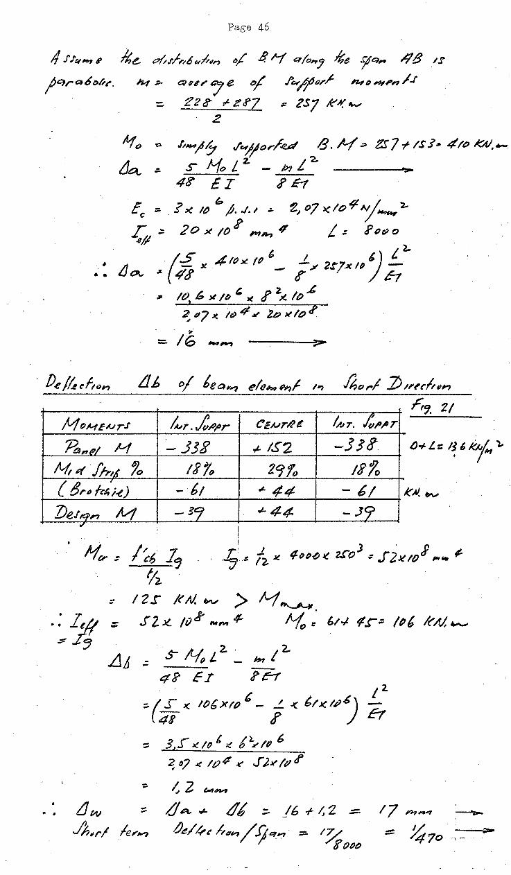
Page 46
4 J'J"~' /he. ~jfr"6«PIIn tJj' .B.~ Q(on:J *e .ij!CJ~ 48 /.f
jqrt:J&ot-". 1'14 ;. 01~"" / e ~f f~u,/- "-'" ,,, /.f
:::. 2'2 8" f- z tf7 .:: ZSJ K'A( 4v
2
o .U-11? c/~jt:Jr/~ /3. N .::s
:. s H~L.z.- p,L 2
4g- £I J' h
Ec :::. ? >< 1~ 6 ,0. J. ~ .:. ~~ oJ "(IO~ Jl~ l..
~ .::. 2 0 X /0 R 1"111,., 4 L .:= J' Ot) 0
G'S ; ' 1 J L'-• ' .. LJ- - ~ ,.,_.tt?x ftJ -¥ 2S"'7x/P. -.._. .,. 4t! - r /' h
"' 10. 6 )t /IJ ~ )( I' z.;( /p""
~ P? JC iu 4 .M" Zo ~lo;p
----):1-
M "/vfEAJrJ kr . .lv/)flr C'£A-~rR~ /AlT. tP/JT
Po,n~l H ·-33J' ~ IS2 -JJ~.
N, I'! lrn.t 7o lit 29fo lifo ( 8r11 ft'/,,J-t.) - b/ .,_ 44 - 6! ZJ~Jtq_n lv! -37' +-44 -.J9
"'
::
.. .
1~6 z, ~
12.!' /(A/.~ > /vf~ S 2 x. I v ~ '",..., ~ f.i =·
s- Jt j 2. . ~~- I 2.. .:: '7(JL _ ,.., 4? Ef ?H . '2
:../S" )( I06XfP '- .!.. < ttKIP-6') -( 4s tf J Er
:::: 31.f" ~II' t )( b 4
Jt'IP 6
~ oJ .< /t) .¢ ..t f).A' ltJ I'
::. ~ 2 """~

Paee 47
.ne a-,Jf,,6 ~I,~.,.., D/ 8."-1 o,ft;,, boll? Cot. SJ.,.,j QM ~ U&~- ..rl-r'} wqr a;r.J'u~eat 4 k j&~,.Cii o tc · 1;, ~,.,0,_., l"err1 Cq/ fp qd,.H/:, ,, . t:J;ete,. -lo ~.rl,-. Qk .L1c:t, a,pt d.( /1-.eJ.-,ur e:r iH"~ qct'~,. Q,k 4/"J(}f.J'~e,f r; ( ~.e ID q (if/ C4~ Oe h1 eu;:Z.) jr,""' wt, cA /:tc. Oil fo ell;, Ct:1;, i:J. Q'IJN,. ~II") etfl t:-;J' r 1/111 N.r ... -
1/.rt.,_ 4P1 t;,-/, CA./
h,et:f'rl c:t'.,t' ~ b ou"' IX&~')' /~p _,~H.
tln/tK..,7 . &~,.r/,,6*/u;l .ry~;- ~Q(/f c:: K-l/-z
. Lt:;qd,7 'JJ~. ()'I ~t. Ji,.1 118,
~ ~ 't2 G- .rlG 7 ~ tri • 4/()RA/. ._ 2..
\Qt I I llfF(I II I I [lJJV
N~ ~ !!;!.l!.!::::. + ~ )( ~ OU/ L 2.. i 4-
:: O,OJ¥1' ~
~ c:, 71r x. 6!''2 x ~
:: 41o ~#. ._
J.~ ]),~ et~~:Jo ~IJ·},~-'~9 /L(t,~,~h. ~ c:,,J'/a,l,
tJ~ :(.:E J( t.f2~f 4- ..!. .X. 34 4i /6 ?
; ~~~r ~ !6 t' _!_ '2.
u ----::::.-
II
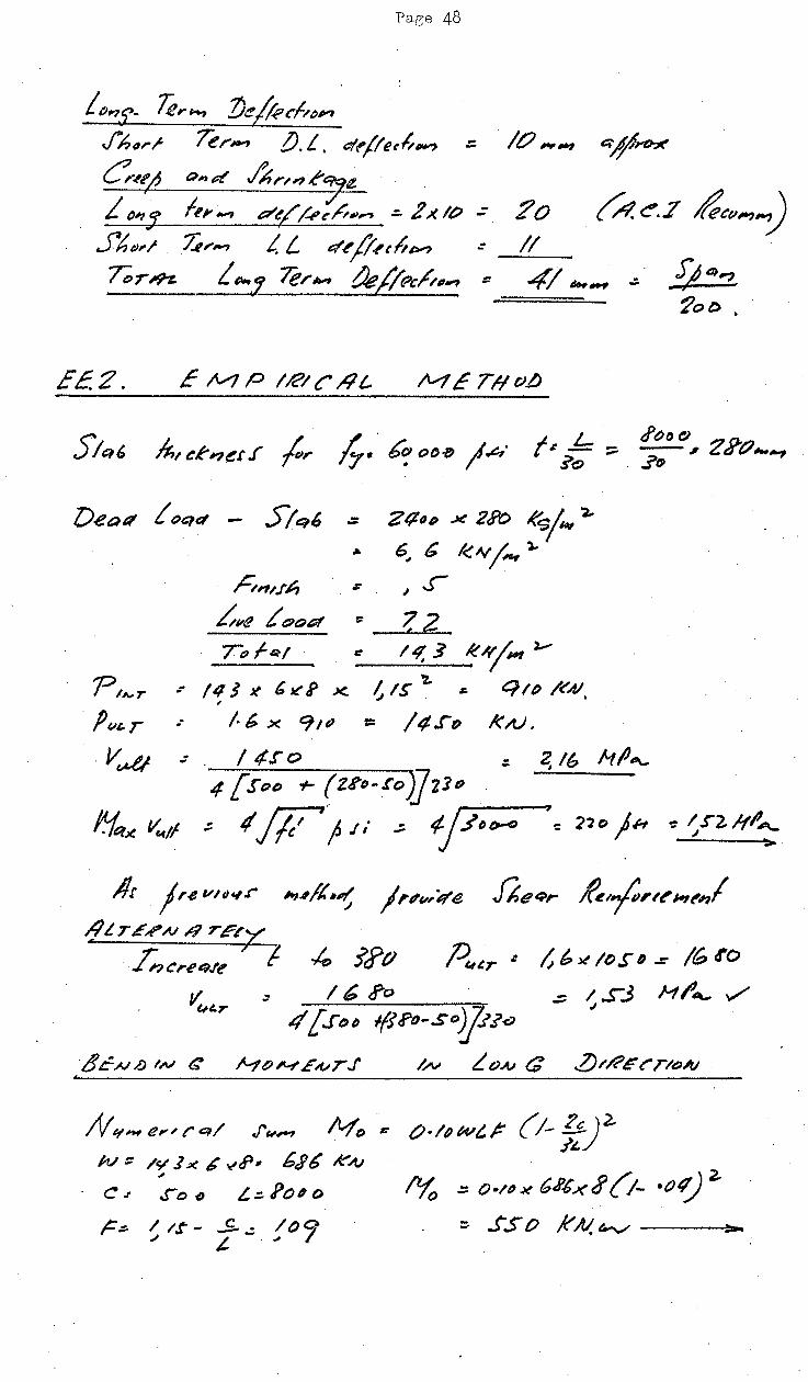
Page 48
L ()"'.£~ Te,.."" ZJe /k cf,. tJ~ fh11rr /e,-_., !J. L. erlt'(le~t'*"
e ... ~ e1nd ..l'hrM~,IZ i ~,. 1~,_, d~/f.,~.h~~~- -=- 2xtP - 2o
~.4&>,./ ;;;,._, L. L et~ /!,(liP'? II
T;rm. L~:J /er., ~;(~h~~ ::: -===~
EE.2.
2~(}1) X 2J>o R~!"' ~ 6, G k~j, l-
,t;,,.f~ ; l..r hve £ t:)Ot:Jf :> ?2 /pf~l t: 14.3 k#/141 l,...o-
- /4$}( {.Jt:f X. -~
~IS 'Z. ;. C}/P /<:'41,
.· /.6 X CfJP = I tt.r~ I<AJ.
.: . I 4ro ::: 4 [St."> "1- (tS'q-Io J]z]u
;: t/ Jll f J / .; ¢ ;-j--IJ_ti-D _ __,., '= '21 o ) H -: ~ $"2,/fl' A-
1/r j re VIIJ&~.r" (/LTE~N/9TE~y
./;.,c,.~~ue ~t /; G ~ /() $" D .r /6 1'0
- / .s-3 Ml'~ ./ VULT' - .I
I 6 J'"o 4' [..Jt:;t> -1(1!'-o-so)jt.?-CJ
Ht;~f;VrJ' bv LoA.J a
/Yo .:: O•/"~ 6J'Cxt! (!- •()4) 2.
; ..rs o k N. '-./ ------1>--
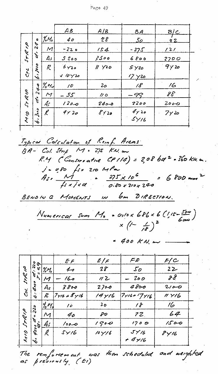
Paee 49
AB AlB BA BIG Q tMo 4o 'Z8 So f?_
~ '> .. N /VI -22. 0 IS"4- - 27.r
~ /21
\ -~ /.1; .S Zoo j'.Soo 6 ?o o 2700 ()
!?. 6 Y2.• II Y2o · Cf y 2o . q Syzo '-J ~ \;· .. " l/)y"U; IJ ylfj "()
/
~ %"tv !0 2o It? IG ~ 1'\l /VJ - SS" //0 -cr:t ?~ ~ ~ ' 4.f 12 ()-o ~4-~ ?'2t;t> 2o o-(;)
.Cli t 1Y 2P !' 1 "}." 4'y l.o ~ .. 7y2b ~
~ .. .!'Yt6 ~
T~, ('~ {?qi~ .. /Qit(}.-. ~1 tf~,,;: 1/r~J · B /1- Col. fl,.'/ li....t ~ 27.r k' A.l, t.e-
R. ~ (' C::~..r,,., &Jt~'..e t:'!? //4) .;: Z: o P 6ct ~ • l(o kN. .,. .
./•.. ~Po ;; :~ Z.to l"'f r'""' . A . A.A · &, l-
17 J' r. '"I . • 2J.J X /() ~- b ~O() _,__,
/.r .1( /." ct o.·d?:J .v 2tfJ~ z.~
IN
P o,!~ .J( b J-t K t (I It"- !J!::!!) . ~ b~
X {1- ..L)z. /tf .
a: 4oo I<" AJ. ~
\)~ Er ~~~ F-R J:-(c-
~ ~ \)" %'~ (-;; 2?' ro 22---
~ ~'I pJ ~ M - I~ 1/ 2.,. - 2t>O
"' ' ~ A"' ]J"H 21b-fJ 4 Pf>.f/ 'Z..-/6--0
-..:.· \}
~ ... £· 7yt~ ~ ¥ytt 14yl6 7yt6.,.'7Y/6 II Y/6 ~
~ 'lo~ /f) 2o 13' IG ~ ~
/VJ 4o po ?Z 64-~
~
~ .. 41 lo~-o /9D..O '7 /') t:;} /..!'"D-0 ~ 00:.~
II)
~ \1 I( S'yt6 /4y/t .f'7't6 ?yt6 ~ .. ~ 4yl6 ~
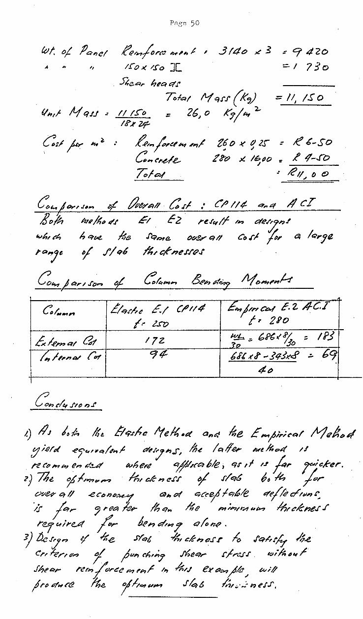
~/~I"~ ~,h.t ~ 3/4t:J ~ .s : 9 420 4 ,. ,, 1.1 o .J( /.f' o ][ ::. I 7 :3 0
5"4e.~r ht'Ci P/ 1'
Tol~t /t1 q.rf (k,) = /IJ IS o {/htf N C!J.l ~ II !.!'""t~ ::: 2G, 0 ,1('7/ 1¥ 2.-
ltf".¥ Pr
~ 0;; 111(1 f4., 'I'J'
lvh~ e4 ~ e,~ fle
/"Q7e ¥ f/~6.
f_e,,f,~" At .,,/
C~~~.u.e.. To I at
t6 o ~ tJ 2s- : /(' 6-So J I
J'~(;) .)(. 16~() r: ~ ¢-..ro I
E1 c 2 . re.re,/f /"? a'.e~;,.t J'q'>~e ()~ Q/1 Co .rJ ;;, ~ /e;-,.jll
~ ... c,r,e.r.r~..r
C/.-~ !'/q.r~~ E./ C~tt4 ,E.,f"nc~ c. 2. .4-C.I f.- l.rv ;, 21'0
£.4-,.n&l'/ at 17Z. ~ -'""~% :; .]Q - 'Jo !PJ
I ~ ;,,,4/ r" '74 ttfl xf! ... ]~3K<f - bo/ . I 4~ I
1.) llJ /,A It~ !/e;Jhc tYe~,t:Jt ai'Jn 16e E;o-.1;,.;"~/ /t1t?$~>~ /1/t;/l'f ..(!1'~'.-~j',l?;t t:lt'/''lh.J",~ lh~ lcttf.er Nt~c;,4 /.f
. n t'o M ~ Rn u:!.-61 lvh (!r..f e;{ll.tc~ 6/e ; q.r I I /J f,. r/ cker.
l} n~ ~~/'??v,-; 4)/ eK;pc.f'f ¥ .r/e,6 "~ #., fur .
~ve?q/1 .ec~>n~>~ ap,t;;( c;c"ejft::th/e 4~/.i?t:/t41"': >:r r,... ~ ,.f?a .kr /1, q,., .Ito Pr;""'t'H ,~ lnte-K11e..r ..1
r.er ~/rut ;:,.. ~ n ~~ y Q;;, 1:.() •
3} !J.e:Jn e;f "*e .1'/e,t ~~ &K'?o.f'.r ~ .fq~,.r~ 4-e. e,, kr,.""' f fun !'h1;,7 .!'heq,- .r~rc.r .i . 1(1;/1, ~~ /'
fht>&'l,_. /"'t!r~?rl"e(! M ,h~ II) '*/J e~PM/k:/ ~ (An"#
jrt) ~Hra ~.e. fh~uP-1 J4& /n_,..,.;; ~-~~J'.f'.

EE.3 YIELZ> L INc /V1 E THO./J
aj' f!.Jtjfq,n ed /.., a,., eql' Iter Jet'f'on { 8 ) .e.<;>ct, · P q, et /; '1? Q,., f/!h,.., qnz !. oq « jo"" .tX;>c4.
Cltr-t cluJn~ a,., ct !fJ,,.,fr..e H,tt; JIJcJ~/4 k. ~~q(IJIN:( few .et'oH-D~J . 71,~ Ll;f,.,., Q/e !o &:~ el II? a-, J' ol/l"t't'~•n If )r'/01""h',.., q/
fu f6.12.. hrAn, er/ C't::t! r"'~ CJ/ ~..e. ?t,J',h&;(! Q.., &(
AleJalt~ y1t/ct ~Jto#-Jenf.r 4CI-6./".I' l6e -t';.,f;;-~ t<.,;, c;tk, ~ JJq,.,ef al 16e t!hfrt>e,/ ;o.r,/,,.e q,d
ne.;et f~rd- h1 () ~n ~, f /12flf,"" J. ·
Ptt~r ~ MocL M, +Hz:~- /t-13 o~-H4-I~ • ftt'dttl
"'htr.t.. M, /t-fz 4t~ 4e. 11-l!.J et ltt..e ~ ~()14-f-'n /-.f Cot . .rfnj t:t~t:?f. Mtt:?/ .. .r/,,f '"44'/· and
II A It A b I ~11!/1( · ..J.-1"'1)) ,...,, f e:~,e rne )o!'tTirAt, IJ.tt~i~W~ ,,1-..r ,.., 1 "-<
C ~ .tfr'l . q, t:t mt c;t .rl-ri;6 re.tf. No /I· /t,qf ~ 11-z. ....! .f.e. C'a, k Ch~J'.,,., q,-!J,/r~r/fy. lfp ~.e(ler /6-e r t:rt h() N, : /tf z •· ~ .. If-f 4- w;l!
Con fr~l f6t. d~th,n f.eh C~ utt#~r "/ ~~ .J'q, t:r-1
t:t( f.tr u.Ptt~ .. Jjr~ cr&:u c '~J hqf tJ('t:4 r/.f!..(;}( q.r w~l/ q.('
hie V'vt,..,., 1_ J'/ut re, .. fr«:.-.,1' -fr tl J'_., o/..6\. 1 .f(a6. ner~ ;;.~ 4e jo#'f/1-'Vtny . ~.f/l'tf>1.1hPII? f ,A(()
11 rec r; ~-H~ l'n Cf'.e.d :- ·
. -
" -6o/, ~ 72t>~ -6o.Y0 ~let -~ - /oi'o .;.lrfo
~ .... +-JoZ ,r sstv .t 0 -1- z.ot 0 D D
flf'/ t:;r.r 2Kc.L >~..r ~I /c- ..5/r<,., &tv Cot. /: ane.l
.E.
t%n: ,. 1 JVo r-Rt~t?re "'~"' f ;.., tY~ 1.-f ;., /l;_e ~~d- .r/ry:r z) p,/ f,~ a; .I 1~/6 ..,/'""' o/ ll'tY~ ,,., ~.f. M r:Jtu;J./,
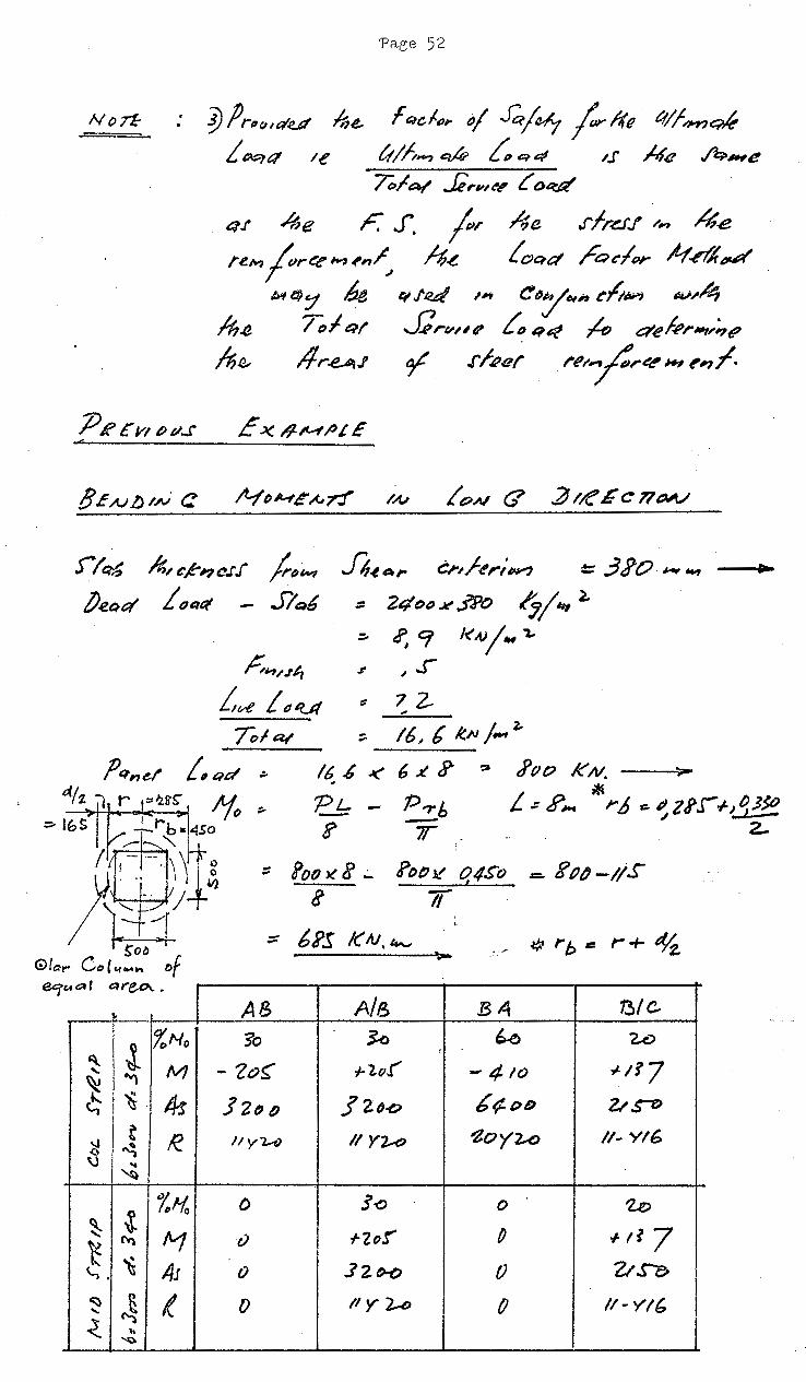
.· '!) fJ r(J ~ ":IY Aie. i &1-qt:f te
fQe-/.",. "/ ..Gje~y /r/(e ~~~~~ tt/h_, ~ f:e:,e~ t.I H<t fi:l.~e
J/Q6 ~~C~"'JC.fJ /rf,IINI fi-t.,.,.. c;~/-~,.;~ = 3?0 ~"" ... J.eQ&t i fJQ&t S/ ~ :: 24 t>" X fPO ~~~~~~
:;. t?,Cf I<A.Jj"" "Z..
Jf ,~..r
" 7Z. .. 16~ b ~/<1 ; ....
l--.... 16 .b < 6 ~ c? tfpo KN. ._..,.
" PL - P,.,.b ? 7f
~ L .:- R.... ~"' .6 c. ~ z tt .r -1-J q .J~
z...
CAc:::tf ~reo....
AB A/B 134 13/C
~·.J. %No 3"o k ~ '2.o
'
''"'\ tv'/ - 2o~ f- lut" - 4to -J-1?7
~liS. 4s ]2fJ() J' 2tJ-o b¢t>D 2./ ,s-t:) ~I I
~~~ I( II ylA) II YZ...O ~OY2<> // .. Y16
\) I~
.:. %Ho () 3-o 0 'Z.o
~ "1 rzor p o~-tl7 t l'wl r)
~ t1J 0 .12. ()-(,) 0 ZISC> \.,,
~ ~ { () ''Yl.-D () /1- Y/{:, .....
-<. 1t '~;)
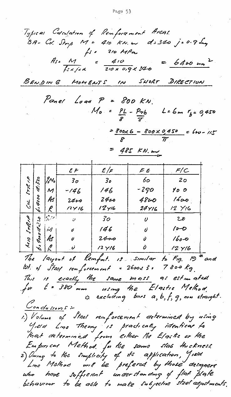
Page 53
T:tjtt' 41 c?t:Vc .. jq/-;,,., ( ,(3;:; _ e~ Jf;-fd M :-
Re~~fr~ ,..,,,_,·r .#r~f. 411) /~N. ~ t:/.; 3¢-o /·~ Cl· 9 L.,
/.r ~ 'ZI'o H/-'~
llJ #- /vf ~ 4 I 0 Z:::. b 4 H) ~~ l,..
/J' ~ /~" e tt:J .x o, 9 .J( J~
I.N
?a, e/ LrJ qq ? =- Roo KAI,
Mf) r: 'L - fJ,.b L t:. {,,.., 'h : 'j 4PJ -;;- 7T
> ?or;Jl" - !-oi!J x. o 4 so == ( kJ- i1S'
a> 7T.
::: 4 i> .r K /tJ. '-"" z::::-
tr- c/;: t:G- r/c. ~ a h/1/o So ]o 6o Zo "-\
"" ~ ~ IV/ -146 146 -zro fD r:> ~
111 /,{~ ~ 2¢~ 2¢-u 4?(j,l.() .J ~ \,
~ R. /2YI6 I'Zyl' 2ifYI' 11. Yte:.
~ ~ k' ·~. v ?o () u f /'I
~ "J 146 /D-O ~ l.;J () d
~
~ ' 115 I) z.~ I) lt~...o ~ ~ ~ l r) 12 y/6 f) /'Z. y/6
1/.e fqo/~~~ ~1 g,~~,(.,i. 1.! _. : . .s,,,/qr It!> F't9. I~ ..M and
/vf. ,; J;4.o/ ,.~,.., j.re~~ ,~1 ~ '2bHlf i, 7 J-o..;;; R~.
11,,.., 1.! .e"'.Q~/y ~e ./'4;tne k4 e;,.rJ' q.r er1M4 q/;u;t
.;."' I sr. ..ltPo ,.,_ t-t./1':1 ~e. E1~!:7.tll~ ft(,~Dt:f', ~ l!..>tc/e,ctm '} k,.J a) b) ~ 'J > I111N ~f/'Q,7t.f.
Co, c/11 .r1 (;),., S" .:... ~._ 1) //o~-8 o/ fi..ec! ;-e,0,cetA?,,., J e:tef.t?r~u,.;,d 67 etf~J>
:;(.etd L/~..t -thep'Y 1.1 jr&J,;, c.e..y l"¢f',.,.h·eev ;4 '/t;q,~ c:reiR,_~,., ~ /r,,_, .e~l6~r- /1~ E/9.r#e ~J' ~.e Etwj1r1 c~ H.e~C)t(. f hie J"~"'e ..r~6 ~rcKnt!'.tf.
z) Cw;,.,! ~ /6e /';;'hctlf f 1f.r o/jfiCCJ>friJn J Jt.eiPI J/#7~ Ntt~~4 ~,tf' k jr.e(~rul ., /4f)#i! t::te.ty~M
~..4 hqPe ./q.f/te/~1 ~,qe,.-.rfQ,.,dh'/7 f j/ct~ ;0/q/e b.c~J.::rvn,e,;- ~ k e;¢k .lo ;,are /~~t~ch#!! .rhel' ~~.1'~~'-'~.l.r.

•
Page 54
f. ELASTIC-PLASTIC ANALYSIS AND DIRECT DESIGN
F 1.1. ELASTIC-PLASTIC ANALYSIS
In the range of reinforcement ratios practicable for
slabs, the moment-curvature relationship is shown iri Figure (23)
below and is conventionally approximated for analysis by ~he
idealised curve shown :-
cl4f'~q,. .. ~ ;> (a) Actual
_L ;; ,. ~I
(b) Idealised
Figure 2! - Moment Curvature Relationship /
If Mp is the yield moment of the ·slab per unit width
i.e. the internal· moment ·at the start of yield' of the
reinforcement, it can be predicted with reasonable accuracy
by
Mp = pf d2 y ( 1-0.59 pfy
. 1 fc
) ........ •.• ....... ( 45)
As the idealised curve is similar to that for a
homogeneous plate, the solution obtained can be extended
to reinforced concrete slabs using the above equation.
Two-Dimensional Solution for an Internal Panel
Consider a uniformly loaded reinforced concrete plate
on circular columns at regtilar intervals and unbounded in
plan. The solution for this ~late can be considered to
apply to an internal panel. A substitute problem is first
introduced. An auxiliary elastic supporting medium is
placed in contact with the plate and all the column~reactions
are applied as external forces. When a single unit column
reaction is applied, the slab deflects into the medium which
exert.s a reaction on the slab for which moments, shears and
deflections can be calculated by the solution of the modified
biharmonic equation for a plate on an elastic foundation i.e.
D \/4~ + 6W .c:::::a t:t ..................... (46)
with appropriate boundary conditions, where the notation is
conventional and ~ is a small term representing the reaction
modulus of the medium.
In the Elastic range and beyond but provided yielding
is confined to a line around the column, the surrounding
plate /

(R20)
(R4)
Page 55
plate remains elastic and the solution for the deflection w
is given by
w +
in v:hi.ch Cl a.nd C2 are constants and z1 and z2 are tabulated
functions of the radial ordinate Hhich has its origin at the
column centre. cl, c2 are evaluated from the boundary
conditions at the column edge. Cl depends on the shear
at the column edge and is proportionaU. to the panel load
throughout. c2 is determined from the degree of rotational
restraint at the column edge and therefore varies after radial
yield. At any point the radial moment Mr and the tangential
moment Mt ~an also be determined as a ~motion bf the radial
ordinate alone. Provided yielding is confined to a line
around the column edge, the total moments Mx,My at any point
x, y in rectangular co-ordinates· are then given by the
superposition of sets of axisymmetrical components resulting
in the follO"Iving :-~
Mx = ~ Mr CoS?. -9-- ..J- Mt- $r., "2.~ ••.••••.• ( 48) L.. Y".,ob
(jO -My L M..- S"h. 1, ~ +- Mr c()s-z.tf- ..•.••••• ( 49)
r:r h
where {j- angular co-ordinate of the column from the
point referred to the x - axis, b = column: radius.
The uniform-loading on the unbounded plate produces
a rigid body translation and therefore has no additional
effect. Figure (24) .shows the moments in the component
problem - a single axially loaded column on an elastically
supported slab at various stages of yield. Poissons ratio = o.
Figure Z 4- (a)
f·o Mp----~-~--
(1>~?0 'Pt
~'Pr
M? ( 'P ~ '2. 11) ?'P, . '2. PI
Figure Z4-(£1 Pl maximum elRstic load = load causing radial yield of
isotropic reinforcement with yield moment Mp.
The /

Page 57
In the case of a ,-,quare panel
pl = -1\T M-p ................... (50)
L • ., rtyt.. + f.~ I p2 - 4'il M ~
Lo~ rb/t,.. +-J.lt .................. (51)
p3 . = I<O Mp - ~rb~ 'lrL.
.........•........ (52)
p = I~ M~ 4
(I 2.t'b/L..) ~ -.................. (53)
P 3
anct. P 4
are determined from statics and. Yield-Line theory.
For a rectangular panel Mp is non-uniform over the columns I
and is given ·in each direction at.~he load P2 , by ! I
Mpx • :lf [Lo~ ~~ -t-1• ~~~ J ............ , (54)
Mpy L rLoj .!:h.L +'2..310..:.. LL~l ............ (55) 4·;r L x ~J
Ly Long\d.irection, Lx = short direction
A summa.ry of the :=;lab behaviour is presented. below
under load incre~sing to the Ultimate :-
Panel Load
P2-P3
p ~ 51) 3 • J.l
(Ultimate)
P4 : 5.35P1
(Collapse)
r'[
Column Edge
Mr
< Mp Mp
Mp
Mp
Mp
Mp
Mt
0
0
Mp
Mp.
Mp
Mp
Behaviour of Panel
Elastic
Elastic-Radial yield at Col.
Elastic-Radial and Tangential yield at Column
Elastic-Plastic: Ta~gential yield spreads outward
Elastic-Plastic: First yield pattern complete
Elastic-Plastic Modified. yield pattern complete
The Moments in a uniformly loaded square internal panel
at various stages of yield for constant Mp, rb = 0.05.1 is shown
in Fieure A.Fl4 of the.appendix.
Panel Moments at Load P2
At P 2·, Mr Mt Mp, hence constants c1
c2
are known
and the moments and deflection are readily determined throughout.
The /

Page 56
The behaviour in the region of any intRrnal column
of a flat plate under ihcreasing load closely follows the
hehaviour of the slab in the component problem. If the
slab i~. ·completely restrained by the column, maximl.im momP.nt
occurs a~ the column edge in the·radial direction i.e. Mr
is the maximum moment. Hence yielding commences when Mr
becomes Mp ,where Mp is the yield moment in all directions,
at a load Pl say. Up to this stage Mt = o. A yield
line forms about the edge and axisymmetric plastic rotation
about this line allows radial slope and tangential moment to
increase until Mt = Mr = Mp at the load P2 = 2P1 which is
the maximum load for ~hich yielding is confine~ to the column
edge. At greater loads than P2
, tangential yield spreads
concentrically outw·ard to cover an increasing area of. plate
with radial cracks. When the load P3 is reached yield
has occured along all sections of principal-moment i.e. along
the column axes and the centre lines of the panels. Since at
load P3
the yield. pattern is completed the ultimate load. of
the panel has been r~ached. The collapse load Pu is reached
soon after with a modified yield pattern.. Figure 2 5 shows the various stages of yield.
(c)f",.-sf Y,efcf. t~-ftu..-.·
Co"'"rl efu~
I -p 4::: 'PIA.:::- S"· ~~ Pt
j
--.. -J-~t ( ot) Moe{, fred.. ?attet~ c()"' pf.c,fu<.
. ~f Col!a~re Lo.,.l(,
--- ....... .._....
In the /
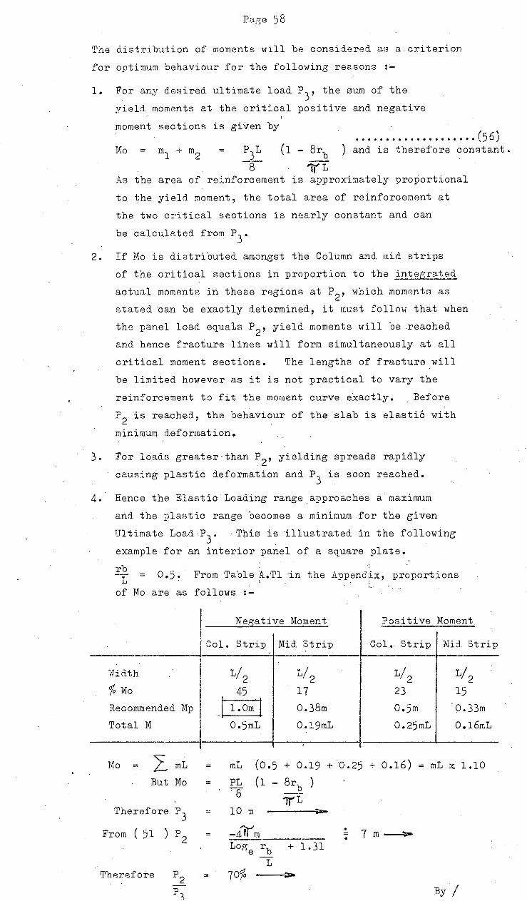
Pa.g-e 58
The distribution of moments will be considered as a.criterion
for optimum behaviour for the following reasons :~
1. For any desired ultimate load P3' the sum of the
yield moments at the critical positive and negative
moment sections is given by ••••••••••.••••••••• (56)
Mo ml + m2 = P3L
-8-{1 - 8rb ) and is therefore constant.
1'(L As the area of reinforcement is approximately pro~ortional
to the yield moment, the total area of reinforcement at
the two critical sections is nearly constant and can
be calculated from P3
•
2. If Mo is distributed amongst the Column and. mid strips
of the critical sections in proportion to the integrate~
actual moments in these regions at P2 , which moments as
stated can be exactly determined, it must follow that when
the panel load equals P2
, yield moments will be reached
and hence fracture lines will form simultaneously at all
critical moment sections. The lengths of fracture will
be limited however as it is not practical to vary the
reinforcement to fit the moment curve exactly. . Before
P2 is reached, the behaviour of the slab is elastic with
minimum deformation.
3. For loads greater than P2 , yielding spreads rapidly
causing plastic deformation and P3
is soon reached.
4. Hence the Elastic Loading range_approaches a maximum
and the plastic range becomes a minimum for the given
Ultimate Load P3
. This is illustrated in the following
example for an interior panel of a SQuare plate.
rb From Table A.Tl ·in the Appendix, proportions --·- = L of Mo are as follows :-
I Negative Moment Positive Moment
l 1 Col. Strip Mid Strip CoL Strip Mid Strip
Hidth L/2 L/2 L/2 L/2 % Mo 45 17 23 15
Recommended Mp J l.Om j 0.38m o.sm 0.33m
Total M 0.5mL O.l9mL 0.25mL O.l6mL
Mo I mL = mL ( 0.5 + 0.19 + 0.25 + 0.16) = mL x 1.10
But Mo PL (1 8rb ) -:-8
1JL Therefore p3 10 m --
From ( 51 ) p2 -Llfr'm . 7m~ -·--· • LOO' rb + 1.31 oe
L Therefore p2 70% >
p By I 4 ';)
J

Page 59
B,y comparison Mp was made uniform throughout so that
Mo mL x 1.10 f6r ultimate load P3
Therefore Mp
From (51) P 2
0.55 m
3.85 m andP2 p3
= 38.4 %
At the other extreme the ratio P2/P
3 can be increased
still further simply by subdividing the column strip into inner/
ancl outer strips of width = L/ 4
and. JJrovid.ing 50% of the
total Negative yield moment in the inner column strip as follows: '
N A:'sative Moment
Col. Inner J Col. Outer Mid Strip
L/ 4 I L/ 4 L/2 lhdth I
% Mo so% X 62 I
=3lj 14 17
Recommended --~
! I
Mp I o.62m 0.38m
I M
Mo
From( 51 )P 2
F. 12. SID1MARY
= =
0. 345m1 O.l55m1 O.l9m1
mL X 1.10 as before
9.6 m and P2/P
3
Positive Moment
Col. Strip Mid Strip I I
L/2 L/2 I 23 15
o.sm 0.33m
0.25m1 0.16m1
1.. If a sq_uare slab is reinforced isotropically to provide a
given ultimate panel load equal to P3
say, then plastic
deformation in the panel will occur at loads /' P2
which is
approximately 40% of P3
• For a load-factor of 2 .or less this
represents plastic deformation within the range of working load.
2. If the slab is reinforced so that the- total yield moment in
each strip is proportional to the integrated moment in the same
strip and the moment in the inner column·strip is proportional
to 50% of the total negative moment which occur at the load P2
co~responding to yield in all directions at the column edge,
then P2
approaches 96% of P3
so that the behaviour will be
elastic for almost the complete loading range. In this way,
the behaviour of tbe slab will be optimized at working loads
and large overloads. By minimizing immediate deflection, lone
term deflection due to creep and shrinkage will also be minimized.
3. If At represents the constant sum of reinforcement required,
the distribution J, :t'l:\.. r •1-n .. 'f ·~ -t
of steBl and weights per :panel
f t {'L. t ·l..!'L.-f ~, t). I rt.. 1" .•l:.l.A"I •~oA-Tj I· • f
-I Pi.fS. 26 Rll.cow....,.e .... ~.tet Mp 1
s -r '- 'ih..- cf_ A.,. .I.. (o. ? g-+ o. 3 0
will be. as folJ.ows:-
r 0..1 {" (....... r
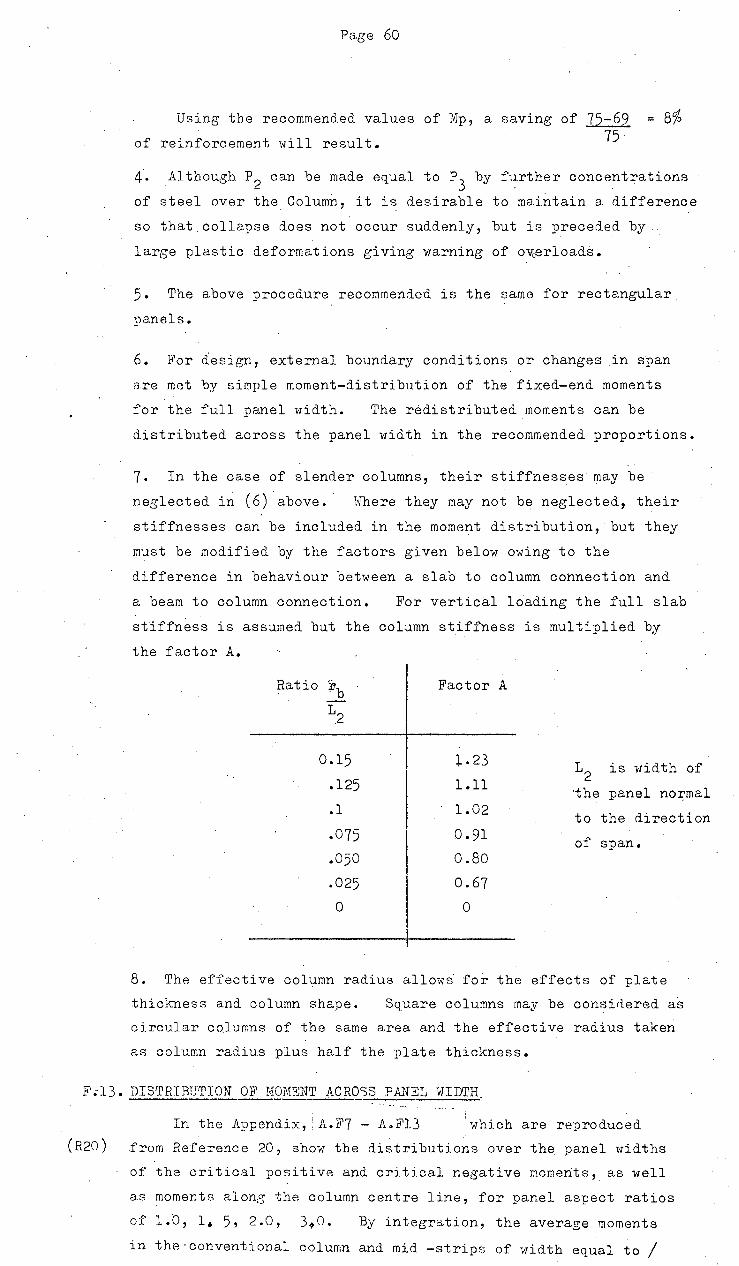
Page 60
Using the recommended values of Mp, a saving of 75-69 8% of reinforcement will result. 75
4. Although P 2
can be made eq_ual to P 3
by f1~rther concentrations
of steel over the Colum~, it is desirable to maintain a difference
so that collapse does not occur suddenly, but is preceded by
large plastic deformations giving warning of ovuerloads.
5. The above procedure recommended is the same for rectangular
panels.
6. For design, external boundary conditions or changes in span
are met by simple moment-distribution of the fixed-end moments
for the full panel width. The redistributedmoments can be
distributed across the panel width in the recommended proportions.
7. In the case of slender columns, their stiffnesses may be
neglected i~ ( 6) above. · \-There they may not be neglected, their
stiffnesses can be included in the moment distribution, but they
must be modified by the factors given below owing to the
difference in behaviour between a slab to column connection and
a beam.to column connection. For vertical loading the full slab
stiffness is assumed but the column stiffness is multiplied by
the factor A.
0.15
.125
.1
.075
.050
.025
0
Factor A
+.23
1.11
1.02
0.91
0.80
0.67
0
12 is w·idth of
·the panel no:r;-mal
to the direction
of span.
8. The effective column radius allows for the effects of plate
thickness and column shape. Square columns may be considered as
circular columns of the same area and the effective radius taken
as column radius plus half the plate thickness.
F;l3. DISTRIBUTION OF MOMENT ACROSS PANEL \HDTH
(R20) In the Appendix,: A.F7 - A.Fl3 which are reproduced.
from Reference 20, show the distributions over the panel widths
of the critical positive and. critical negative moments, as well
as moments alons the column centre line, for panel aspect ratios
of l.D, 1. 5, 2.0, 3.0. By integration, the average moments
in the-conventional column and mid -strips of width equal to/

..
Page 61
to L are sho>m in tables in the Appendix as follows for an
int~rnal paneL
Table~.Tl - As percentages of the Static Moment Mo
Table~.T2- As percentages of the Critical Moment
Codes of Practice Distribution
For a square panel the actual moment distribution is re·placed.
by the step function shown belov1 in A.C~I. 318. The arbitrary
proportions shown are used in the "Empirical Method" and. also
the"Elastic Method" irrespective of the aspect ratio. The
tables above show that the codified step-function may be only
applied to square panels as for large aspect ratios the variation
is too laree.
E.G:j(..lfl/o.l-t ~
S~tr 1w~~~
4. ~:.----:---~---:::;::7 · A c.t c.t'lf ~ o .....,, .. t
c1, sf-r,n ... +,a"". """ 0 """ e."' f. .-=:;--~ -t--;;--;~"'7-1-"
o{,;f-,. b .. huVI Mo""'.t"'-H.
+IlL- 1'1o w..t "'.f..:t
Fig. 27
'For example for ~ =· 2 and rb = 0.05, the distribution of
negative moment k€t1veen the ~;glumn and .the mid-strip is 57 : 43
in the long direction and 91 : 9 in the short compared with the
recommended 76 : 24. For positive moments, instead of the
60: 40 recommended distribution-it is 51 : 49 in the long
direction and 86 : 14 in the _short. However if the panel is
partitioned·differently so that the width of both column strips
is equal to Lx-.~y_ where Lx, Ly are the panel lengths, with the
middle strip1t6~));ing the remainder of the panel width>the codified
step-function distribution will closely resemble the actual
distribution for aspect ratios from l : 1 to 3 : 1.
Alternately the· conventional division into eoyal widths
may be· used. provided the division of moments follov;s the
recommendations in Table AT2.
As there is a high-concentration of :negative moment as the
colnmn is approached, it is desirable to subdivide the column
strip /

Page 62
st~ip further in to inner section of half the column strip width.
The moment in thA inner Geotion shoulo be 50% of the total pa.r1el
moment.if the ~eoommended partitioning is used or 67% of the column
strip moment •f conventional pa~titioning into strips of equal
· i>tidth is used.
The h<o alternative distributions in Fig. 28 are therefore
preferred to those recommended in the Codes.
I
(-}¥e. M ~,,,.,,
I r, I I •
r-p
, ... ( -l:)w, M I ·~
4.,' ---- __ .,_
z...,/
(-)~L fv1
r:~(28(b) flt. T~/?N //TIIIff
Cotct_,,· J).,.t
~ire cIt~.!"
---- --- z,.., , IJ•66P, I
% ~,7,, I ?c.
p,% :-f
" .., /DO% Jti32 'Tq 6/eJ
I ;r,. ,q ~"~ I
.: Pa·~ r .
--,., Ly,
. .2) ,.rf-1~, 6 M ~~"~ q~ t?#? q"e~
.::: L.x . L v / Lx + L Y h? ~~
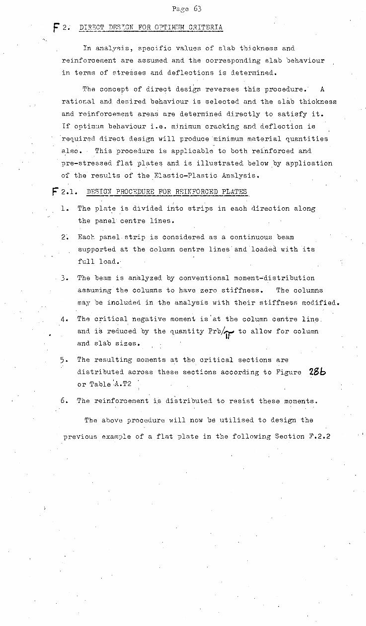
Par;e 63
F 2. DIRBCT DiiiS:WN FOR O?Tirv!TJM CRITERIA
In anal~rsis, specific values of slab thickness and
reinforcement are assumed and the corresponding slab behaviour
in terms of stresses and deflections is determined.
The concept of direct design reverses this procedure.· A
rational and desired behaviour is selected and the slab thickness
and reinforcement areas are determined directly to satisfy it.
If optimum behaviour i.e. minimum cracking and deflection is
'required direct design will produce ·minimum material q_uantities
also. This procedure is applicable to both reinforced and.
pre-stressed flat plates and is illustrated below .bY application
of the results of the Elastic-Plastic Analysis.
F 2.1. DBSIGN PROCEDURE FOR R~INFORCED PLATES
1. The pla~e is divided into strips in each direction along
the panel centre lines •
. 2~ Each panel strip is considered as a continuous beam
supported at the column centre lines and.loaded with its
full load.·
3. The beam is analyzed by conventional moment~distribution
assuming the columns to have zero stiffness. The columns
may be included in the analysis with their stiffness modified.
4. The critical negative moment is'at the column centre line.
and is reduced by the quantity Prb/~ to allow for column
and slab sizes.
5· The resulting moments at the critical sections are
d.istributed across these sections according to Figure 28b or Table ',A.T2 ·.
6. The reinforcement is distributed to resist these moments.
The above procedure will now be utilised. to design the
previous example of a flat plate in the following Section F.2.2
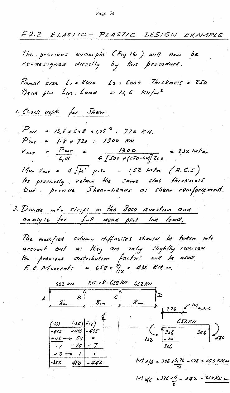
Page 64
1="2.2 EL.JISTIC- ?L/IST/C :DES/GA./ E)(A/v?PLG
The. prev /CJu r exq_. jle · ( h1 I~) wtl! no..v
re-ct~.rtyne.d oltrecly ~J It;,,;· Jre:;cr;d~r~. 1 6.e.
~n~ S/Ze L 1 .:;: Fot~o Z}~c;,d Jl~t Llllt . t OQd
L 2 .:: 6 oo o 71uci'nerr .#" ?~o
=::.. /~ C !<AI/.., z.
Vu~or ,.. Put.r- ::. /300 '=- 2JZ MfJ-., 6
1ot 4 [".roo ~(z.ro-~1Jz"o. · ;
M~ v"'r ~ 4/j7,.r., - ~rz M~-.. (n.~.r) /i.r ;rl11-"tul!'/y > refq,, lhe .rep_,e r/t::~~ /h., ~kn eJf
btv~ )r•t~~d~ 5heQ,.-/1ee::utr qJ .riJtJ&~,- r"tn(orce~"~'~-1.
Z. VtvN;te '"" ~~~ .s-1-rt~ r ,,., fle f'lld() a'tr.t eft#, Qil'f4 , a, ~:rre jir L"'/1 oleo~ ,PI"i /,ve 4~&1'.
n~ hfpt:f,jte~ Col"'""~'~ .rh/fnerr~ r .riJDu/a' k la-,t'~;, i.,h
~ ~~(1t.tlfl;. bwl en /1, Qre o~"~,Y . .rhy~.l~ , flC:t'"' e./2 t>(
~ /a~lorf lha · jrllil '""J' ~.rf,., 6 "'/"' 11"
F. E. /VfPMenff ::;. 6.fZ Jc! ;?. .:1
IZ
,$2 kAJ ~IS' xJ>.:.&s1. RAI
A t Bt cf .. 3,.., .. g-,_
It "1 'l "
-.fl.l -14~S -4JS"
+l!fl ~ S"1 t>
-7 -I£~ - 7 .r- Z. --?> I •
l<.n/1 k t:; J' (Jt:(' . 43.!' RN .... . . .
,:. l U' (A?'~ 1 , '.rz ~A) t:~~ Jq' 1 ~~·
]b'
lv1A(s:. JP6x!:_E -122 ~ Zs-JkN.M. "2
/V1 e(c r:. J 2 ~ ~,!. _ 44 2. .. t..t oR u. ,___ 2

Page G5
I
/VIA~~:~ Jzz- ft;6 :x.o,3KO . iT
~ ?Jf KN. ~ ~
MBA:. 48'o- 6?'2x o_.3Ko 7T
:::.. J g 4 k AI. 1--1
. -2J8'
'
A8 A/13 8A 8/C
~ () %/VI 44 *2~ 44 23
'
~ t· 1\,) m -12Z. lo -- 16 'l bO II
~
"' As 1 too /Koe> SD~-() lSD.() ~ ~
~ ~ ~ R /() y'2• . t Y2.D I& y~o Sy2o . ~
' \.) \1
" . %M
() 2Z 27_ ?Z 27 ' .\; ' """ 6! 70 - s-.r- 6o
~~ ~ -"' t.. ~ A.r !6oo /J'()(;) . Z S()ei~ IS'" tJ ~ . c, te\ ~ " ..... Sylo 6 yz.o ?y7..o .Jyzo ~ ~ ·~ 'q
() %Nf 34- 4.f' 34 4r ' ~ ' ' 1/..J -122 '77 ~ ) H"' - 1 S'"
"' ~ A.r 24co 290-D 3 3o~ ZSot:>
~ J>y2o ..... ~ I< ?y2.tP /P y2o I/)' lD
~ .. "'Q
4. S"tl.n::ttv 'f tPH
oft.rfn 6 "tfl'_,
ti? I o .rfrtj11" q ~cQ,. .tf,.., ~ ~P IIJ -1! r ..
( ft>t! /q6/e A- )
)t 41f. ;A"
),; 661.
~
*
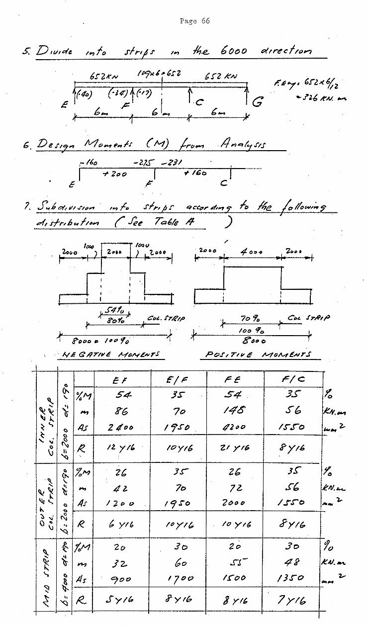
Pag0 66
,,
1 I
t c
1. ..5:.6 oil 111../'lp,. ,.., ;/,. .1'1,., .r eu:eor 41#"1 fo ~e
&~'(, i-fr,6~1~~~ {fee Ta6/e /f )
r:-~'7· G.rz~ ~2 ·
... .? 2 6 It' AI. """'
__ :,----:___ [
... s4to L
/( ?o ,0
" C~i.. I'T~I/' ~;c..· -~--=---;I.J~----
~~---------------1' f ;'"DOO ~ /#t:l fo'. "[
eF r/F r£- r/c Q
~ XA1 S4- JS S4 3S
" ' ..... 'I 14'6' Sl:> ~~ ) ,., ?6 7o ~ ~
() 4.1 2 1{0/) 1 r.r() /12110 ls-.ro ~ . ()
' " ~ 0 '.R. 12. yt' /Oyt6 Zt yt~ ?yt6 \J H ~ "
(I %M 2' Js- Z6 3~ Cr-.
'\\_ '- s& ' 'I 4l 7o 72. ~~ ~ ~
~" () 1/J' I 2 o o 19.!'0 "Jt>t>D 1.r.ro ~ ... ~
... ~ ~· ~
t. Yl' ~YI6 \) ~ '4 R. It' yt' /() yt6 \) ~ I
~ ·~ (oM 2~ 3o 2o 3o
.... ,, bO ~ 'ti- 14-? ]Z.. SJ- 42 ~
..... c:. lis ~()0 '7"0 I .CoD /).)0
~ ... ~
~ •• f<_ Sy ;rs, t?ytb 3 yl/, 7yl6 '<:l
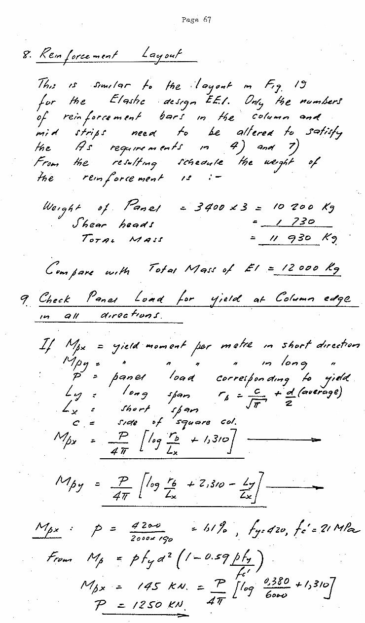
Pag~ 67
1S .r;.,., /qr J, Me . / QJ ".,,t. ,., h J. I~ jpr !he C/q.rhe · a'~.rlj,., £E./. t?,y ~e Hu_,kr.!
of re/n for("~~ l'#?f . IJqrf II? 14.e J Ct:J(~.,,., <:J.,,f
MiA .tfrijf nee.P( fo J..e c,!/~re;f lo JQ/!Jj/ Me. /1 .r re~ ,.~~ ~ ""' ,/J II? 4) q,,. :} rrtJM ~e. r~J'.,;Jtl',,. /'~~4!a'~/-e 16~ ~'9h,l-. ~ he re,...,/orre ,.,I!, I- tJ :- /
Wa/4 ,t. ~1 ·~...,~/ - .:i ~op .>t' 3 - 10 "ZQ() ,<' -. Jheetr hflqlfll' f .c: / ?.5o
ror4l- A4 ,q .t.f - II CJSO K~ -
C,..,IQ"" ..- tv/ &j.{J· tJ/ ~I 12 ()(7() £, evtft? I o.fet/ --
9 ChecK fJq#?.tl../ ! (;);, q /or tj;el~ ~~-- ~lw-., ~~Je .. "
1"'1 Q// t:f,re?c ~'t.JI? f.

f . .:. JOOO
/SD() Y Z!O
Page 68
M4Je, r /tAHJ 1/~l~e.r ? =- /250 KIJ
Ct:)/"I''.JI ()~ df
ref,cfed 1-~J.e. · lo~ a· P 'Z ) r~ tnt~~rfy
qr et. · e r/fe ,..,~) So !h e;l- lvt,P vqle-(-(!;1
orf l~e. e l"i f, C&:r I .re ~ f, P,., .r a yfJ ,_, q "'.e } r o J or f.ttJ,., 1&11 I
De.!- / &In .e./
1:~. Pen.r
R e~~,...~.s .·.
:;.. P.r .X. / Of:?d r;,~fQr -= 6s 2 .x. ~ C)
:::. /3 04 K N.
The /Jt.:ln e/ will jail qf- P~~. r ~ 13 04 kN 6::1
/DIO/'VJ7 ,.~ !he S"horf e::t,.recft""' Lx. &?l~e fP S'11w ~tf"e~,eo~.r yielct Q} lhe.. crt/ice;/ .rerf,~,.s:
Be f(lte. P .::. /2 .!"o kAI J , lh.e tt.A CJtNe>~r w;# k e/t::~..rhc UNit, ~/I?,.HitU#fi'1 def/ecf/(1'?,
/(). Check 2Je,lkdn~~ f .
. /",."_, ~J "ZI MJI er,f~t~l,~ ¥ ~e /Q,e/ c,,-, I-re i J' YN''I'? ~ L1"" z:. L1 cv -1- Ll&
wher.e Llct..~ ~t c~- k eJ'/;_,q/Q~ D;t ·~e / r.e t/,.e~~J ~ e ~ t:~~ ~./""'J l»e c ok~+~,-, Jl-n} 1\-7 16e 11)nJ olt,-~ef,t:J~"~ · t:lniPI' /he ,.,/t:f-sfr;; In 16e .rhorf.
/-lf /~e. lf.t~ ~t? _., t'~~..f are .1/~,'/e:n- '" fce,/e
lo M~ j r.e "' P~J H'f o ,._,en :I ..r 1
.L1 W ltl;~ Je .rhy/,//y ler.t a'.,, lc;> Me h'}he,... 11dfq/;v.e
JY!(}M en/~ . O;,e?(' r&~~/frt't£7 ~ {)~" qr ./h,e /#"J/.e~~·Q,_
.!'t-t/jtJr,L t#? 16e _foi?.J .q,.,.."c//p,.-, > UJh/ch
Jt..?e::ttf'e.r ~e JrRe;-le.rf CD~f;-,t "'/,.eJ,., lo /IJ11 ~e'foc/io,.
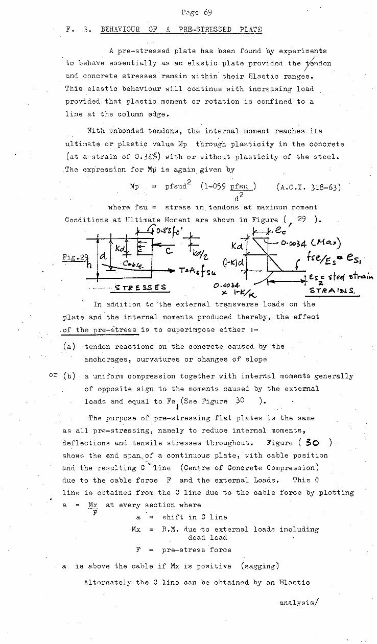
PR.ge 69
F. 3. BEHAVIOUH OF A PHE-STRF.SSED PLATE;
A pre-stressed plate has been found by experiments
to behave essentially as an elastic plate provided the fnd.on
and concrete stresses remain within their Ela~tic ranges.
This elastic behaviour will continue 11i th increasing load
provided. that plastic moment or rotation is confined to a
line at the column edge.
1h th unbond.ed tendons, the internal moment reaches its
ultimate or plastic value Mp through plasticity in the concrete
(at a strain of 0.34%) with or without plasticity of the steel.
The expression for Mp is a.gain given by
Mp ~ pfsud2 (1-059 pfsu ) (A. C. I. 318-63) d2
where fsu = stress in.tendons at maximum moment
Conditions at TT1tima.te Moment are
--+-t--J~'Jr. _IL-r.r O·I"S fc 'i; sbo·wn in Figure (
1 29 ) •
~ec O·oo34 (. M c:t,-)
F1· rt -25l q• -h c.. ~t.
~--~-+--~ I~A,fs~ ( f~e.lt:. s • es.
~-r-~----1- e.,~; $ reef 'Sn.Q :"' - - ---·- -- <; "('"~ e. ss E' s ST,eAt'NS.
In addition to 'the external tra:nsverse loads on the
plate and the internal moments produced thereby, the effect
.of the pre~~tress is to superimpose either :-
(a) tendon reactions on the concrete caused by the
anchorages, curvatures or changes of slope
or (b) a uniform compression together with internal moments generally
of opposite sign to the moments caused by the external
loads and equal to Fe (See Figure 30 ). I
The purpose of pre-stressing flat plates is the same
as all pre-stressing, namely to reduce internal moments,
deflections and tensile stresses throughout. Figure ( 3C> ) shows the end span,of a continuous plate, ·with cable position
' ·I'.\' ;·~
and the resulting C 'line (Centre of Concrete Compression)
due to the cable force F and the external Loads. This C
line is obtained from the Cline due to the cable force by.plotting
a Mx F
at every section where
a shift in C line
Mx = B.M. due to external loads including d.ead load
F = pre-stress force
a is above the cable if Mx is positive (sagging)
Al t!"lrnately the C line can be obtained by an '!'Hastic
analysis/

e E~t
!. 8
./vf
a.f
x.x
= M
x.}
tt )( ~
c..
C\.
1
e-z.
·t
_ ,
, F
> ~e
.r
ZJp
t;t;
( -t-
L ,~
=·cz
)
t "fx
• J
""-.. =
Fe
, r
Fez.
Non
: C
.,,.vt:tf~re
q.,.
ct
e'l'
~/kehP
#'I
~1..
~
ct.
~ c.,.~
( C'
~(~
/,.-,e,.
) a
.. d
e
... /,_,e
.el
~e
1-~
F
,; ce~~/£
~~
co,.
,~c:
;r&f
q,. f
Bc,.
;M
Ct.
E v
,tt/
7 /
'o""
'-'
·
,c
q.,.,
t:Jt
/oq~/ ...
7 c:;.
C
.'].e
.
e.....
---
,_
-~
a,.
e.. r
e I"
' k G
t ,C
,. F.
p
N =
~ ~ (
Nr .
.Af.,.
.c,_l)
~ f
1 t
t 1
t 1
t _ tA
1 t
1 1
t t
1 :
1 1
; ~
1 1
1 f
F
J, FB
FR
Gf!
... 4
,()y
~~
CDAJ
CR
ErE
I
rt:}
rA'-t
. r-oRc~.r
,&
JeO
I'-f
C;
rt~B
'~~
&>
N
c e
NvC
RE
Te
•
/?N
tJ
Cdd~£
p,
G:
3o
ro
p (lq
(D
-..3
0

1 ~ ~
t: "Q
" ....
"'
Page 71
(/
analysis of the slab carrying the external loads and the
cable forces shown, from which the internal momentR M are
calculated. ·
l'oo
1410
ll,1o
lo~o
Zoo
= M is then plotted where F
= distance of the C line from the c.g.c.
~00
4oo IJ/1,_ Qk l.rfr~.t.r ,1 It Sfra;,.,
. .
leO I 0· rg loo 14.
0/o c;; T" ~ Auv t.r
Figure 31 Typical Stress.:.strain curve for pre-stressing steel
DEFINITION A Concordant cable produces no external reactions and
therefore its compression lirie coincides with the cable.
NOTE
1. Any real moment diagram by any external load system to
scale, is a location for a concordant cable •
. 2. Any C line is a location for a concordant cable.
3. Linear transformation of a cable does not change the
position of the resulting C line.
4· A parabolic cable produces a uniformly distributed reaction ~
on the concrete = 8Fh per unit length where 2
h = total drape of 1 the parabola (Fig. 32)
Fig. 32

(R4)
Page 72
By the methods of analysis previously described using the
-auxiliary elastic foundation, external moments Mx, internal
movements M anrl hence deflections can be calculated as before
for any axi-symmetrical loading system. The uniformly
distributed loads Pl > P2 on an internal panel correspond.ing to
radia.l yield and tangential yield respectively are related to
Mp as before.
Using the load-balancing concept, it is obvious that the
cable profile and tension can be directly determined.in order . ,, If
to balance the sustained load QS exactly. As explained later '' II this is a desirable criterion. At this loading QS, the
internal moments in the concrete are zero anrl the centre of
compression is everywhere at the middle surface.
As the loading increases, moments are produced and the
centre of compression is displaced. The maximum moment is
the 1 radial I ,moment at the column edge where the centre of
--'
compression is furthest from the middle surface. As this
moves below the mi~dle third, the top surface moves into
tension and later cracking. As the crack progresses downwards,
the centre of compression drops to reach an extreme value.
The internal moment F x a has reached its constant maximum
value Mp at the load Pl allowing plastic rotation of the plate.
·Thus an effective yieid line forms around the column face and
the tangential moment increases-with increasing load until it
too reaches Mp at the load P2. vli th further load, Mp spreads
along the column centre line and then along the panel centre
line parallel to it.
When Mp is reached along the entire critical sections,
for both positive and negative moment at the load P3, a complete
yield line pattern is formed representing the ultimate flexural
capacity of the plate.
Hence further desirable criteria would be that . . ' Pw where Pw working load so that the plastic
moment is not reached at working. loads, and also that P2
approach P3 (P2 ___.,.. P3); By realising these criteria
deflection and deformation at service loads and overloads
wbuld be a practical minimum. It ~ill now be shown that all
these criteria and others can be achieved by direct design so
that the behaviour is, op.timized at all loa'ds and so that the
cost of the structure is not affected.
BEHAVIOUR CRITERIA I

Page 73 .
BEHAVIOUR CRITERIA
The tendon pattern in an ideal pre-stressed concrete
flat plate should satisfy the ~allowing criteria :-' .
1. Ultimate load should be attained with a minimum number
of tendons.
2. Deflection and cracking should be minimized at other loads.
3. Deflection should be zero at sustained loads.
4.• In plane stresses should be a minimum
.5• Tendon profiles should be identical smooth curves.
These criteria are desirablB for obvious reasons,
but criterion (3) is desirable for several. As the concrete
is everYi-1here in pure direct. stress, no bending and no deflection
occur. The deformation due to creep is uniform over the depth
arid produces no deflection either. Hence long term deflection
is a minimum. The slab is also crack-free and water-tight,
brick partitions are crack-free, the elastic range for lateral
or dynamic loading is a maximum and overall maintenance of the
structure is minimized.
A solution is possible by the following procedure which
satisfies all these criteria very nearly.
F. 3.1. DESIGN. PROCEDURE
1. The plate is divided into panel strips in each direction
2. The panel strip is considered as a continuous beam
supported at the column centre lines.
3. The plate thickn~ss is determined from the ultimate
shear or from the deflection under full live load.
4. The beam is analyzed by conventional moment distri.bution
carrying the full load assuming the columns to have zero
stiffness. This assumption is allowable·since at zero
rleflection no moments.·will be transferred to the columns.
Negative moments are reduced by Prb to allow for column
and slab size. I1' " ,,
5· · The distance e of the cable from the middle surface
is made proportional to these adjusted moments M. At " , the columns, e has the maximum value of half plate
thickness less the req,uired cover, and the cable is rounded
over /

Page 74
over a width from 0.31 - 0.41 to reduce friction losses. .. If
6. The total number N of cables per panel width is determined
from the Ultimate panel load and the correRpond.:i.ng numerical
sum of the total ultimate moments at the critical sections. 4 II
7. The number n of cables per unit width is made propo~tional
to the distribution of critical negative moments across the
panel width at the loa.d P2. This distribution varies with panel shape and is approximated by the bands shown in Figure ( 34 ) . For ratios of L greater than 2 . 1, . adopt the latter distribution. s
8., The effective cable tension To (after losses) is determined
to balance the external moments at the sustained loading
and is evaluated at the panel centre giving
To = M Ne
~t 1 ~eJ::.: ·I~~ 23
. F!9 33 L ()~t~a'""7' H()WI ,, ,lr , calk 7-J,.e.e
r- .. 7S?o _'£D~ -- •w l
o/'l,. C= LJ<S L ~s
-% ~,. I I .r, .. .,,q jt:~t~ e (
34
'RecfQ~., ..,/.,,.. 'f.J&~~,.,e,; v
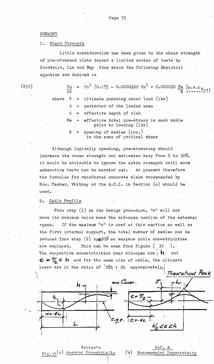
(R32)
Page 75
REMARKS
1. ShAar StrAngth
Little consideration has been given to the shear strength
of pre-stressed slabs beyond a limited series of tests by
Scordelis, Lin and May from which the following Empirical
aq,uatj.on wa.s derived :-
Vu fc1 (0.175 1 0.000020 Fe )p. s. i. = - 0.0000242 fc +
bd s ••••.•• (57)
where v ultimate punching shear load (lbs)
b = perimeter of the loaded area
d = effective depth of slab
Fe effective total pre-stress in each cable prior to loading (lbs)
.S = spacing of cables (ins.) 'in the zone of critical shear
Although logically speaking, pre~stressing should
increase the shear strength and. estimates vary from 0 to 30%,
it would be advisable to ignore the extra strength until more
exhaustive tests can be carried out. At p~esent therefore
the formulae for r'einforced concrete s·labs recommenried by
Moe, Tasker, Whitnef or the A.C.I. in Section (c) should be
used.
2. Cable Profile
From step (5) in the design 'procedure, "e" will not
have its maximum value near the mid-span section of the external
spans. If the maximum "e'' is used at this section as well as
the first internal support, the total number of cables can be
reriuced from step (6) by~20% as maximum cable eccentricities
· are employed. This can be seen from figure ( 35. ) • . I h
The respective eccentricities near mid-span are i • • • j
and
·e. » ~-<:. h :and for the same size of cable, the ultimate
approximately.: I
loads are in the ratio of ~2ih·: 2h 7/,eorehcqf Peq_t
:r.~_tv I
_Ref • .A_ (b) · B_ecommcmrl erl l':ocentrioity
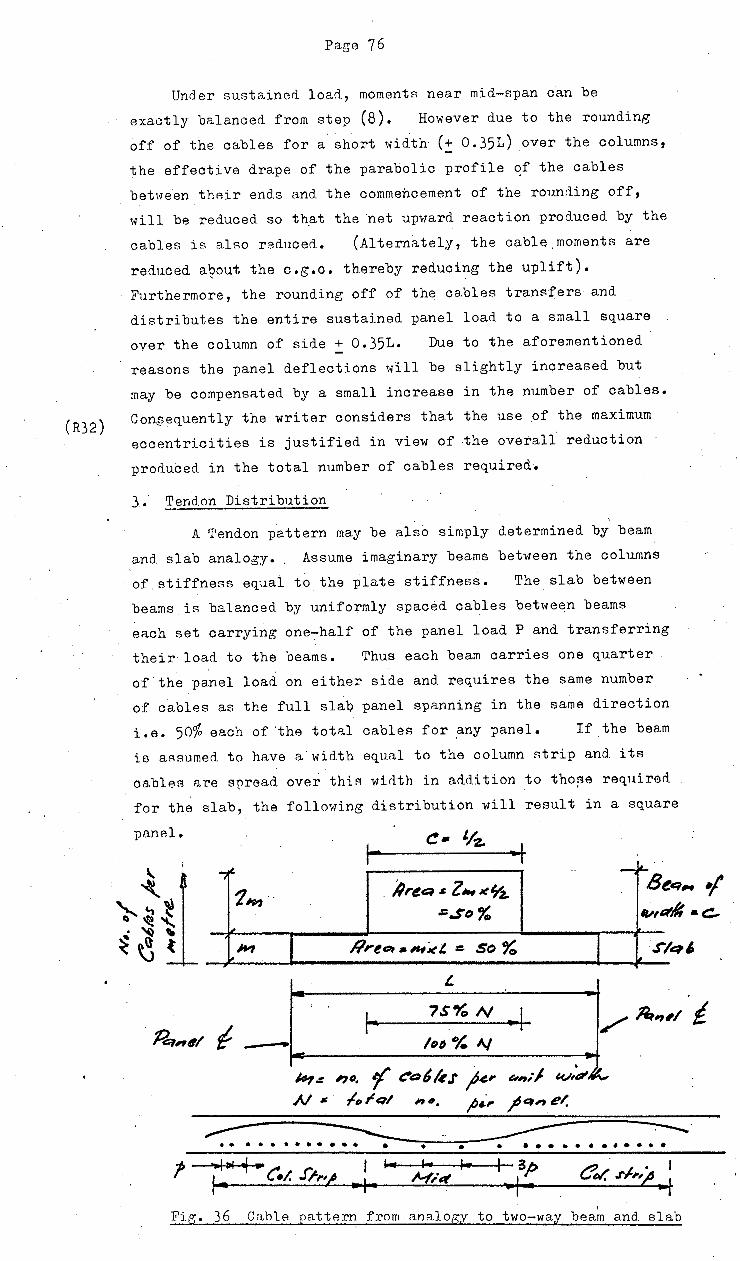
(R32)
Page 7 6
Unci er sustained loan., moments near mid-span can be
exactly balanced from step (8). However due to the rounding
off of the cables for a short width (:: 0. 351) over the columns,
the effective drape of the parabolic profile ~f the cables
bet1-1een their end.s and the commencement of the rounding off,
will be reduced so that the ·net upward reaction prod.uced by the
cables is also reduced. (Alternately, the cable.moments are
reduced a~out the c.g.c. thereby reducing the uplift).
Furthermore, the rounding off of the cables transfers and
distributes the entire sustained panel load to a small square
over the column of side ! 0.351. Due to the aforementioned
reasons the panel deflections will be slightly increased but
may be compensated by a small increase in the number of cables.
Con~equently the writer considers that the use of the maximum
eccentricities is justified in view of ~he ove~ali reduction ·
produced in the total number of cables required.
3; Tendon Distribution '
A Tendon pattern may be also simply d.etermined by beam
and. slab analogy. . Assume imaginary beams between the columns . .
of stiffness equal to the plate stiffness. The slab between
beams is balanced by uniformly spaced cables between beams
each set carr,ying one-half of the panel load P and transferring
their load to the beams. Thus each beam carries one quarter
of the panel load on either side and requires the same number
of cables as the full slab panel spanning in the same direction
i.e. 50% each of 'the total cabl eB for _any panel. If the beam
is aAsumed. to have a width equal to the column strip and. its
cables are spread over this width in addition to tho~e re~aired
for the slab, the following distribution will result in a square
-I "';i~
_, ~-
1#J1 . AreQ J: z.,x'l'z.. 8 ..
=.so% ~,
li
WI I llrttt:~t • ,_,~t. =- so Yo I .r:
L
?S% N .... j
H-,.r 'JO. '( t:*a~/e.r ~,. e.-,,;1 t<.~,d/,o... N • /, rql n •. ;; .. ,. _pet, e/,
. . . ......... . • • . ... -....... .
FJ.g·. 36 Cable pattl'lrn from anA.lop;y to two-way beam and. slab

"
Fig.
(R40)
Page 77
This distribution is identical to that recommended for
square panels,, and oan be applied to rectangular panels using
the width of oolumn. strip determined from
c - L X s L + S
••••••••••••••••••• (58)
4. St1dden Collapse after Cracking
The oraoking moment of a pre-stressed section is
the moment at whioh ft • maximum tensile stress • modulus
of rupture (f ) r
f r is gi van approx. by ~-3_0_0~0~~-3 + 12000
p.s.i •••••• (59) ·
fo1
Cracking will continue if the tensile stress at the top of
the oraok is greater than f • r
In slabs or rectangular beams
with unbonded tendons, F = pre-stress does not increase
significantly and is assumed constant.
M
Slope dM do
1 3
~ 0 for stability at cracking
for -- _.c = o : dM • - l rbdf · - F] >: do 3 L r
If F < bdf dM is < 0 and as soon as the r , do
oraoking moment is reached, the seotion continues to oraok .. and becomes. unstable, leading to sudden collapse.
has been experimentally verified:
The ..... theory
Hence as the tendons in slabs are not usually bonded for
economy, it is necessary for the average prestress F to be bd
greater than f • . .r This requirement will safeguard slabs against
sudden collapse due to overloads or earthquakes.
5. Effect of Rounding .Profile over the Column
From the analogy with the two way slab and beam, it
was shown that the sustained loads could be balanced everywhere
by the oable reactions exoept in the region of the columns.
In /

(R.4)
Page 78
In this region the cables have negative curvature and the
load iR transferred from the cables to the slab. If this
transfer is axisymmetric about the column and. is concentrated
at a line of effective radius rt' the concrete slab is acted
upon by Z. ring loads of magni tua.e P, upward at radius rb
and downward at radius rt.
The deflection at the panel centre
The
·uniform
is
ratio
. =
of
load and
3
0.019
this deflection to
zero pre-stress is
•.6(rt 2 - r 2)
b
Hence To should be increased by
. the
L 2
this
which for 0.125
6. Effect of Partial. Pre-stressing
••••••••••••• ( 61)
deflection under
proportion
is a correction of 5%
This can be achieved by the addition of non-prestressed
reinforcement throughout the bottom of the slab and'over the
-interior columns, being desiened for the Ultimate Load a~
which they will be fully effective.
However, the non-prestressed reinforcement will not
retard the onset of cracking but once this has occurr~d, it
v1ill reduce the severity of cracking and increase the resilience
and ability to absorb impact loads.
Where the ratio of live load to dead load is high say more
than 1•5:1 and where only a small proportion of the .live load
will be sustained for long periods, its use is recommended
as a replacement for some prestressing steel, but further
research is necessary.
For all other flat platf?!s, a small amount of non-stressed
reinforcement is recommended say 0.15% of the gross area of
the slab in each direction, as a supplement to the prestressed
tendons.
The previous example will be designed as a prestressed
plate using the procedure outlined.

Paee 79
F .3. '2. ])~SIGN or
.. L t/: . ? ()OO .S:: t OeiO
/& L =--4t~ 1Jee:t#l L1:1ti?t1fll •• .FIRt .# Z 1/QI l(" ~~IJ .:. ~ 7 KN/~ 2..
I. . lhtl('~ ""1~ tp,.
!V/odH ~.r. { ,f 7INA3
.. /2 4- " .. ;
0 ' fr~~~ fi* (r1) /r .; J 4 tJ IJ c. fZ'D} J)
.3 +- I Z 1111 o
.i#f/1111
(R40) Prp~,qfL tp IAJ,..·
,..;_,. a.-~r'j" jr~.rlrer/ • fiJD /· .r.' .;.-J.
(R32) ·"
(R32)
hiJ'AA .. · /~ 4 ~ 6 ~·I' J1 ~IJS 2
• ~~I> KN. >-ErA, {.rl) . . . . .
Y~r ,. /~: 'Jpt ~·'J-'"- u. ~"'oo z.t~z/t:" ~ (),,,,~ z 6! J . ... 24 .., -~ " .. , .. ,; ,. .r· r o. , ~ ~ Q, ~""() 2, z. .., 3 4:o] . · l_+- /). ()()~~ l J( JiJP.J( 3
: 7 2"P J( (;). /.)7
c /26, K'AJ. .....
F ~:u,l"p,. ¥ J eYe~ /t:l~ .r~ ./Jeq,. je,, ~~~ .:: /. '7 u> J,n"4 /J
~, /1 -ie ~h,r,f~ ,q,;,. t-41 ~"""'
/,e:rv,.e k,#"' C1'4fer~"#.~-t.
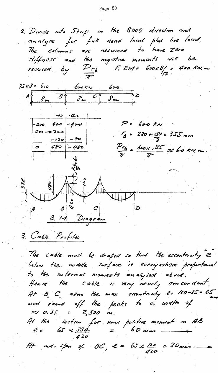
'·· :.-z
Page 80
16~ <fOtiO dtr~ c./,,,., qnc:( 2. 7) tt.~,cr'e ~ ... f~ Srr').r /1?
· <=ln etty.re jtJr j.,l/ ctaaR /oqd }l~.r t~.e ~q~ . 76.e. c "I"'_, 17 s qy(!. CU.I'1~e~ .J.D h~ve zero
.r/J/1, e.rr t:l;oq ~~ !?":/ erlt"" 1-t-t ~ ~ "" l.r w;' k re q., cee:t by 'Prt, F. EH# bf)fJK~ ,~. ~11eJ ..t'N.--.. ,-,-
iS'~J'. (,U) .t~K~..; 6HJ
AJ . J'., gl ?,.., cf ?""- t~ •/,D •ct-.
f-4/HJ. /If><) -(~
~~-,... _.... 2 ~ I -/ '2.0 . - S"'o .
~ . 0 .-12<> ,-4h .
~ li
~~ j 4
-~ -~ ~ ' ~~~--~,~~~~~~~~~~~~-+! I~ . I • r. "i~ C'! j.ll
8. /t-1. . ·ZJ,&-f'q_.. ' J
3. Ca6k .. P,.,(f.e_
1"1 '
?he cQ61~ ,.,.,.rl le d'A/,c:t .rD ~q/ ~~~ ·~~r,,l,,.t,f,:t "e • . . kl~..u .f!,e.. 11-fl 4~/~ .ru, I 61C~ ; ~ ev~'Y IVI,f?,-e 1/"Y)I#I,.pPtl"tq/ . fo ~t.. ~ /~,-,.; Ql IJ.ID~l!# h a;, 4~ .Ia&:( 4/, IIW',
/f~,., (e M~ t' t:J6/e. . /1' llttr7 ,_,Q,.~ ~,,., t:'t~r e/4,f,
/lf- -~ C::. q#o"fJ ~e, ,.,qx '"'~~~"'~7 -f',- /t?t'J-.J,r, 6'~ e1~e11 rDt,~tt:t Y/ /Je, . je~rr ~ c:t w,.q~ffi P;J' . ~ o. 3 t ::. ~.5t?() ~.
IJI- .fhe · . .le~l~~ /cr . /t.f4-< jp.t,h~ nt#H#',,c. ~'~~"~ #/.> · e ::::- b.r ~ .J J> 4=: =- 6 o ~..,., _. _. ----~~---
.42-P
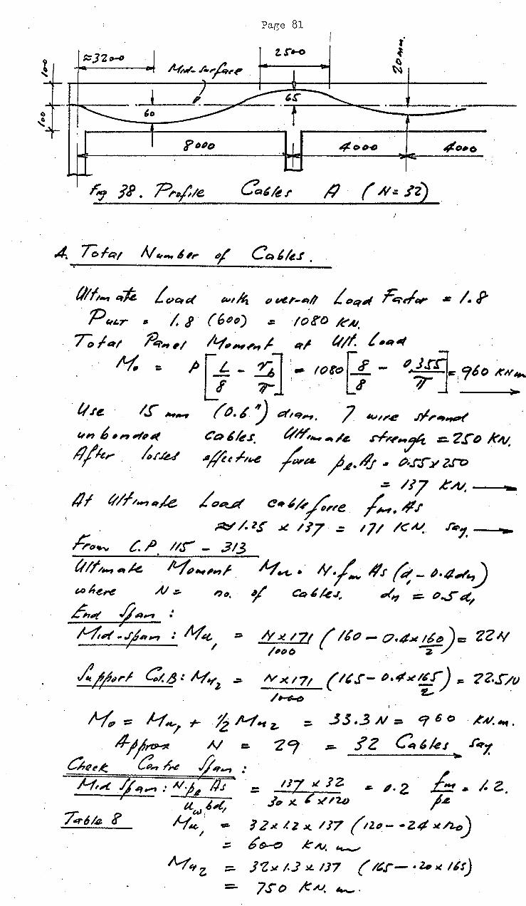
Pa~e 81
. (//ft., ~1e. fcn::t~ "''~ P~,.-~~1/ f~>q~ ~~~ • /. P . P ~t.r , I. I· ( 6()t~) ~ to!'{) /~AI: /; f•t /?:;.~,I /1-f,~,, J q! 4'//. t.~tll/
H. " p r _f - ~ l :- I08'ol1.- I? J.ril., <fbO ~H.._ ~ ~l ' ~ 7] ~
/.j ,..,.,.. {(). 6 :J a',q,_,, l w~~4'!' .q,. .. ..,t ,
e,, 6 .,.,",~ co~le.r. tit¥;,_ .,.,4. d,y-Hr =- '2.f"D k.-v.
4/k,. ;,, ./U #• ,t,t-4 /wa. ) .1• if~ . ";.r.r y l.f"''
. 1/f 11/l/o~• .,,(e. .(.,~ c .. ~H ~,e ;et:l' /. lf X /17 .:::
.::. /17 ..t'AI,
/-- #.t
h-~~ c. ,P. //.j - .313
tt //;~,.., 4lt k /Vfp~ ,, ;.
{,() he,..e AI .::. , ~ .
.6,~ ~ 4Qi'f :
H,,( ~,..., : M'~ ~ ~ /
... ~ ..... ...Y/- #J ~- ~-4~.J
"/ Ca ~ /.e J.. ~~ :::::. ()...;Itt/
~,::71 ( /bt7- o.-tx !.f")= ZZ"' N ->U7t ( lt.r- "·"'"'¥) ,.,. 72-.0v /~
I - 3.$ ._3 N = &f 6 C) · ,l"Q.-.. -
=- i'Z C 'kJ .rq/.
1'7 ~ JZ. ~ ,. 2 ~. /. z. . .J, ;(:? ~I '2.o 1.1.
1 z~ 1. z JC. /J7 (tz#- ·z.t~ x/l..e>) .:::. b t>-t:J K N. 4....,_;
::::. J~~ t..J :£ IJ7 ( ~~r- · z. x 11r)
7S'o ..k~ ~· --

A/=s JZ
I,. .,t::f N I' <.A'
Pa.ge 82
I
-- J!x 117 c. ~.l.tJ ,1~ x. tx /(~
&, j.J
/e
IV( #t,l · ::: .? 2 11 /. J xl-17 ( /trJ- ~·l/J~ 1/0 .,.:. 1/() ~.~.~. ~ .
H. • N"; +- Yz M.,_z .. 7lo + ~ j( 7J'b ::. 112.!" I<A.J • ....., >! q Go kN. .._.
nt:
z:: I'
c ~ tu1art t c~! .r~,.~ L Jt s ~~: ;,(6 L+.f . er~ &
'C
1 tlfz ~ /l?i. t r •4
r-' ?.)D •[
r(?..j' Sot> 1 .$.: 611ll D
--4-
~-~ft-,.,_ .. ;.~ .,4 ~q/q~~~ ~ .l'~f&tl';,~ .
~qA'. 6 t::?/Q~t",~ f:?tJ~t't;6~) ~/" ~ ~11M?t'H/.f 17 /6"..,· ( ~~~~~~"~/;.. 6-,/q,.,,,~ t:'"~e~.;_)
gA-, Cp, t~j4h /rtu:~.,~e "' C- ~~~ ~ ~,,{11'/e 4'f"'q('e /-t'.
H.-'~;~ c~~r,~
J",., ;..,. (I II¥ ,,.,k ett'/k~~IP#t.l. ~,...~~/t,,Hf.

Page 83
O.eP.-:t' '"~ • . ./:.~/ .. _...., /.., ,.-• J t.L
/;..f~ J;.tl~~ut' . hq.lf '
,6,4 ~ .,..., : lvf &fx j, rn"t.e. "' ".._ ""' f . qti! .li..tfq,..,_, 4.,d ::;.. ~3 84. X ~ 'l: = Z3S A'"N. ......, >
. /2 4 ..
~ jr'f;r h,_. /n..- ~ l<fQ~~/ ~~~.,!,_,, 7; .: A4 .r ~e,..e
N X. e:. lvfJ• 41,A,,.#II/ "'~ .!)(~ r~ k ~
...r~J ,t-.., u( /.,q .{ AI :. ,.,. . •/ Ct:~6/e.l q~~
tC r:- (!q//e '4t't'",,~,.,,7 ~ fl"';, a..,h:, .
7; = 23~ :;: /3.3 A'~ . ;/Z X (). 'JtJ
4a~L ~.r.ld .r:: . /~ '6 J'S
.... /7o R~ >-
bJit, 'I 4e R//. A,.~
n.L o#lt4~ ~ ?_ /S" ~ ... tl ~~ 6~~~~~UJ( Cte:tt/u
, l"~e.,u·~ /J .3o ~c~I'/A. Q_., ;..,,·h .. / h~.ho.-, t>f !?S K ~. = 74% f Af4 1111. Sf,_..,1 .«...
?l-t! CRI/e /,.0/e /.1 ./~e.-~ k 1.~ ,_ · , .. Z4oo ""I

Page 84
N.:: /o
.. 8. n.s. N ~.~,.., ler /)I' ~~' te.r . ~ n . Per ,.,,~I ;,~7 A.
. -o., .r ,,r I""/";;.,, .. ,~ .,~ r-;;t , 'uR. c. "'~ 4.)
/O .
. 7le _fo,t~ h~>. i CR4/u ,~,, 1//p-.qj, £Qe1 ~ 24 b.,l ~/J · h~.r ~ 6e. '""re~.r~ ,t" Jo
.I
.r" ~ ~f lie ~t::ll'~ 7;1-1.1'/,~ 7; er/~ kJ~t.f (A.h# ~ f.rt " t~ it '/ ~~ P/f,,..,~k ~tie ·j~''/ ft.. n,.r /I Cht~l'!-ul 41 ;, 1/tJ~.f . . /-
..e;, f1041'1
i-t.: Jo
ILfet )t. ;~r,f,~ ""() ,.. ,, I ~f rf ~ 6 k,vj., ,_ . M.s ~ ( t ~ '!II/( AI, WI ,
/2 '1 <I
7; • H.r 6 IJJ J 0 Jt ~.04()
177 KAI. ""~· >
·:::..
• S!.4 ~ till /lr"7 ~
/J 7; J:( .
/,,Itt:~/ C:.tk ~,t'e
_C_CI_b._le __ !__,~·~~
1-~1 ,{;tAl
/.f ./'h~,v #'? ,_, A:"'j' ~ C:#?~,.ele a,~ aii!J' /J' ,(' (1-S"o ;,_, ~
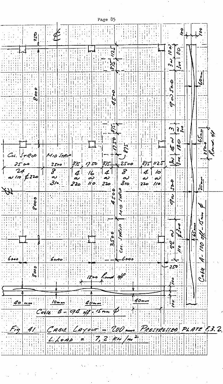
Page 85 ~----------r-.--------~-r-----
1
I " I ' ' I ' I ' I . ' ''I I I I I'
1 ~ I , : , I ' I I
I 1 1 • I I I!' I
I' t I' It 1 t
I I I I j I I
I: I I :; I I I'
I I:: •!
I ''
1-:-:-:-~f''l . ' o ' ' I •
."'-l~ .. n~- ~ I
- ·~4 • I. I , '' I
'! • j
___.~~ ~ ,........,~~-~-~- \S. (.)-~ - ~-:-:-
I I j t I' I,·, I I I i l .I .,.,.~-I .,, .. , 1•1 ~- ~- - .,
j f ,j 'I '' I'
I i I ~ It t : ! 1 I I . I ''-= 11 II, I t I ' • I il't,.'t•l I'·· •L___._ ''I . ..l 'I I 1.~ 1;"~: .... ,.j ... 'I ! l, I: I "\
I •
' ' 1 • I r-' ' ' I t ',1_ I 1-t ,., II t ' ' r ,,.., I I I' t C , p •
I I I : i' I' I " • i I I' I c:...-:: ' ' ., I I I I ~ ~ ' '· I I I 1 I I t I 1 ' I t i I i I I I ~; I I j I I I I t I I I I ""i
I' I' .• I. I '' t'
I'.
I I I I • I l I ~ i 1 I I ~ I I t I . I ~ ~ h. _;,_;..,1 ..,.·..L 1+-1 ..!.1-l---1 -'--1--i--·'-·-1..,.1 -1-~ .__: __.J ~· -~-,,___...___,-,_..--II__,_._ ~ l..,.--....... -f--+-..,--,_,..__.+.._,....,-,_;::-r--'-- ..--. . I' . i' I I I -
I j t" ~ t I I I j I I I I I I ! l i ~ I 1 I • I ~ I I I , .. I ' j I ' ' 1 I ; :. '
.• ''; I '' ! ·,; '' I,,. I I I . iII 'I '' tl 'i !l·j I I + .. I • t- I I I I t • I I ~ j I .,1·. I f • . ·l j I I I • I I I ~ I I I I !
I I ' ' t 1 ' I ! f t I i t t : I I ~ ; I : I I I I ' ; I I I
t' I
' ' • t • I. I t I>
'' I I I
I ~ i I
• t • It t •
·· 'J,,:i;~ '1:,. I• ~1:1 1 'il 1 ~1 !J.I ~;! :; : ; : : r·, , 'I' 1_- ~.~ ·~~ :,~ :1 •. ~~~ i' 1-i 11: · __ {\ '1 ! i I I, , I
I ' ' \) I I .& I ' I I I 1 t' ! I ~ ao· l i • I • I' . , " I l1 -~~~:H.~. -'--,--'-+--it-,__..1+-
• ' ·f Iii ~I 1 ~ j; ~ i I! ' ~ ·,I·):;: o t ,1 'I! I
' I t • i I l I ! t I !- ' ~ I I I t ! t l I . I I i- t 1 ' t 1
'I' 'I
_;_,_-' . . '
-- [~-• • t 0-
~:. --
I' I : ; ! ! j i i 11 :_ ; ~ f ' l j ! ~ -: ! " ti.-i j l ~ : ! : ll I : ;: 'li _'.:1. ,l,· ; : I I : ' : : : I 1' ' 1 t t I I I 't ,. ... j t t ·t ! I I ~ I. I· t • t I I ' . 1 t I ~ ' t ~
t- I f I f I I I f I "". .._ : ~ l- ; 1 1 I ~ l • I I ; I f . j I I
------~~~~~~~~~~ ' ~ 1~~--~~~~J---~~-1------1---- 1-----, ! . -II t I i . i ' • ! I I . . . i ' ' I .I ' ', 'I l- . . __, '-- : -- -
• • I ~· _. ! i
', '' ~ .. ~ ; ... -~~r~ ·I .-
•
0
• I ~ :: : ~ : I : ~ 'r' : : ·~~: 1
' : ! t 0
'
1
• ·"1 a l • _\..}--.Iff,_ "'~'-' ' ' I ! I ' I : ' ' ; ' I I I~- I I" ; ' I' I i J, ~:: 1 - '__.;r- ~
:. -::::·,·I ... ::·_-.: .. ' I :1 :: ·r::- , :; I.;:.~ ::. I. :1.:::, l':t-.... 1 {): . ~ ~ I ,. . ~,·-. D~~~- "-:-:-l., -:--:----. ~L ~ --~ !-If-:-' f
• I I j 1 J
:c.,. J,net.P : 1~~b~~ ... r· :·· .:1~+1S:;;;- . :::·.·: ··! ::!~. · · ~~ L.· .J.rD--O ZS<-f) lcr~ lt;-.ro' ~~S:~~ZS"oD!! J.~/.r 1f12f ~ ~~- " 1 '24 · · , ? 1 .:: )4:1_ ·/b· ~I.¢' 3 I' -14 ·;o! -:-lfi-- -I~
· «/Ito '/Z'Z.D av ; 1 .c:v . ; ~: • 4tJ· e:V iV t:1V 1' \
. : ~; ·:·.-: ~~.·---~--~---~---~ -!-:-~_to_.; _____ -+-.2-2_o_·._._~;_"l-o-:_iz_2D__._· I o ~.3~'-o __ · f--";l~z.o--'· :,_~._'/a-+-+--a-=-~-_· ._.~ -'-!--<-.! L·A·-+---~ •jl ••'I•• ,, I< till-()$ ''I I< ,...r--
: :. I :- : i ; : .; t t : 0 : ~.:· 1 1 1 : til ; ~ I ·I ; : ! ~ ! ;. tt I -j t !
1 "1 \:__- I j t· t • j ; :· ~ I jl :: t1'~ It' I
l I t "'- ~, j • . R t- t j • I -l • . ~ -f I f l t i 1 I· •• t· It· I' ll, I •• ~ , ~ t II II ·,· . I ·I t t ' ' I ~ ' ' I . + ,. - t ' ~ I I I ' I I 1 ' t ' II 'li ' I . ' j ~ • -f t- I ~- ~ • I I· • ·, .,_! i. ;. !. I ~- ~- ...~· ~ j. j ! .... · ~ ! !: j • i I I l ~ t I I I ~- i + I' I· l J I •
1 0 : : ; : : ~ ' '·; ! • ~ o ' 1 1 + j I L I· ·I: _;1:J -~: ,1~ t __
1l· tl:.· .'
1. o ;- ; : -: ;. i , . " , ,
1
; ; : ; 1 ~ ; : : ; : : 1 '
_____ ··-·-·---·-·~---~·~·--11~·-·~-~·~i~j-'~~~;-_,~·~~--~·~+~~~~-~·-t~-~t~t-LJ~:-· ___ • - ~--~1-rl~·~~~~~~·~l~i-;~f~t~-1~ ~ -----~ t : ', 1' I . ' • ' ' i I t ; j '·j j ., t + I ·I ,. + j____; H i ·- i ~ l i ' . . ~ lc- ' ' I ~ i ; i ~- ~ j I 1-I- . •'-..JI.-' I ·t I 1 ' -1- i" +- -I ! +·t t + ·t .. 't : 1- t· I ! 1 t--·t l t 11.- ~ ,-1 ~ t ! . ~- . .,.1 I I+ t I I
• t + • + • I I f • I --j ~ ;- ·l . t ~~· ,· ·,. ~· t ; ! _,. t L . t- I I I ~- j I t J., I I I I . I t- t t l ~ t '
:::·11:: .!~.:: ·- ~~:~ -:t -~:;rc~·;:~: ::n~·t::: ~~~- ~;: 1,·::-r:f:':: ;;;~ J:_ :;:;: ::~ ·~:~ .·.-.-~--·~~~-~~-.. , .. , .;·o ·~~ ···tl :r, w.. .. -l
I I ' I ' ' ~ I I A • I ; I ; ; ~ : . -~~ .... rt. ·~ ri·· 1 "·· -~;-:-c; ~ :;: :~·~ ~~·~·~-
• 1,. • • 1,., , 1 I I :::: r; + 1·ltfH; ;.; :: 1· '1::; · _CV)
1
. ~. 1 :·; 1 i i J •·. !1' ~: -.. t\... o· I 1 . I t I I I I i 'I •,· t 1, ,, ', ... L ~.·- ~.·. •l ~ : I I l ' ~ l f ! 4•; ' I I t f ,~ ~
j j I I. I l I'. j I I I 'l I I I. I' .\J I' I J. I'. t i It i I ~· ~ •• I I ,·_' . t- ~ :.·- 1.· j ~- ', j t: .. t j t •. 1 • ' I I !-- •-1 I t I ' J !- '•' . .- . ,,
't. / • I~ I • I ... ~ I It. j 1 I I -~.·. ! If I. I· I I ' i
~ : . o HtJ .. 1 t :6~o ; f. ; : ! 1- : . , : - tl-00 ! t ' i I , • : U ~" ~ ! ~ t 'i 1
'' -1. 1-1 1 f -1 ·-t 'I'!. 1:1:;
'.' i I
'. '' t
·. ... ..
0 I
. ' 'I
'I
I
'I
:.-----L -
• I : ''I- ZSD ~ : 'I
! '
t-+ I t- ·i·1
I I • I J_,. ~ ! 1
• I
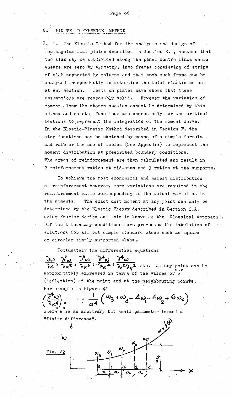
Page 86 ·'
I -
G • j FINITE DTFFERF.NCE MP,THOD I
G. j 1. The Elastic Method for the analysis and design of
rectangular flat plates described in Section FJ.l, assumes that
the slab may be subdivided along the panel ce~tre lines where
shears are zero hy symmetry, into frames- consiFJting of strips
of slab supported b,y columns and that each such frame ce.n be
analysed independently to determine the total ela~tic moment
at any section. Tests on plates have shown that these
assumptions are reasonably valid. However the variation of
moment along the chosen section cannot be determined by this
mA"thod and so step functions are chosen only for the critical
sections to repref'lent the integration of the moment curve. . .
In the Elastic-Plastic Method described in Section F, the
step functions can be sketched by means of a simple formula
and rule or the use of Tables (See Appendix) to represent the
moment diFJtribution at prescribed boundary conditions.
The areas of reinforcement are then calculated and result in
2 reinforcement ratios at mid-span and 3 ratios at the supports.
To achieve the most economical and safest riistribution
of reinforcement however, more variations are requireri in the
reinforcement ratio.corr~sponding to the actual variation in
the moments. The exact unit moment at any point can only be
determined by the Elastic Theory described in Section 2.A.
using Fourier Series and this is known as the "Classical Approach".
Difficult boundary conditions have prevented the tabulation of
solutions for all but simple standard oases such as square
or circular simply supported. slabs.
Fortunately the differential equations
~~ ?}~AJ :O~w -~4CA) ~4w ))(.. .> o x'Z. > 6~3 > · ()')(4 > ')l(~d .... ~ etc. at any point can be
., " " approximately expressed in terms of the values of w
(deflection) at the point and at the neighbouring points.
For example
(~)o \\ /I
where a is
in Figure 42
= __!_ ( t.03 +W..,- .d.w -.4w + 6 w0 ) . 4 . ~ ' 2 Vl .
an arbitrary but small parameter termed a
"finite difference".
Fig. 1£

Page87
Any rectane;ula.r slab may be then arbitrarily sub-d.ivid.ed
into a sq_uare or rectangular mesh and the intArsections thereof
(nodal points) numbered. The governing biharmonic equation '
-- •••••••• ( 62)
r ·~· . . . . .. *·· . ~· .• • ~ ·- - ~ .. -. --- -
at any nodal point is then expressed in terms\ of the deflections at: L . .
surrounding points, the mesh size and the average loading at . the point.
For example from Figure 43
1 where w 0 - w12 la~~---! the values of w1 at J?Ointf o - 12 shown
ltJ
~ .. r s
Fig. 43 IZ 4 0 !z lo ~
7 ~ ~ ' ~ II"
In operator form, the ge~eral operator on the deflections is
-~ ,,.._, ll ~- ..... ( 64) _,......_, -
J)
At points on or close to the slab boundaries the general operator ·
can be adjusted provided at least two boundary conditions are
known e.e;. a simply supported edge·has
:-0 ) and
a clamped edge has etc.
:=.0 )
In I

Page· 88
In this way the biharmonic equation at each nodal point
can be replaced by a finite difference approximation.
As many simultaneous equation~:can be set up as there are
unknown deflections. These are represented in Matrix Form by
[VJ· [w J - ~4- ••••.•.•••••••.•• ( 65 )
D [L l [V]
-'
is a square matrix n x n
where n = n'umber of ·unknow·n deflections and row "J" represents the operator pattern at nodal point "J".
[w] is ~ column matrix 1 x n representing the
unknown deflections
column matrix 1 x n representing one of any number
of loading patterns
is a constant representing the maximum loading at any
point and. the slab and mesh parameters.
The "n" equations are rapidly solved by electronic computer
for each loading pattern. Having obtained the deflectiom
at all the nodal points in each case>the unit values·of Mx,
My, Mxy etc. are then calculated at each point by finite
difference approximation using a different computerprogram.
For example
I
where -t)-" ..
D = Poissons Ratio
Eh3 -.,-;- 1 12~1- "\)""")
Flexural Rigidity of the Plate

Page' 89 L
FURTHER ADVA"NTAG.ES
1. Provi.ded D is constant th~oughout, ·the Moments are independent
thereof. The values may be used to determine whether the section
is cracked or uno racked a.t the nodes and then the effeoti ve value
of D calculated • Ey introducing these values into the equations
. a new set of moments can be calculated and the process repeated
until the moment variations are relatively small. In most
practical oases, these will be no need to proceed beyond the
first set of calculated moments.
DISADVANTAGES
1. From the values of Mx, My determined at each point)steel
reinforcement can be provided for the full width of the grid .
.. (half the width.on either side). Less steel will be required but
·the extra labour for detailing and fixing will only be justifie~
in the case of large numbers of similar large paJjels with heavy
loading.
2. Column stiffness cannot be taken, into,acoount directly
unless the columns are so stiff that no rot~tion is possible
along the column centre lines. Such oases are exceptiqns.
In all other cases, the column Moments. and rotation l~~ :=: M j 4~Kc must first be calculated from analysis by the Elastic Method.
E.l)so that the deflection~ of the ~lab middle surface directly
pver the corners of.the columns (e.g. Points 1 - 4) are known and
can be used in the· difference ·equations· at adjacent ·nodal points·
in a finer mesh which picks up points in line with· the column faces - .
(~.g. Points 5, 6, 7 and 8).
lr Cot..
M,e(G(f~- ~ .. f~c~. @@)
, I 2. 7
e< ~ ~ / . ·t(; ~
3 4 ~tj
8 c---9.)(,
• 5 ~ ·er
b
' ' <t;.
Sec.T,oAJ
Fig. 44
..
:90 Page.
TbiR finer nat RlAo on~bloA the determination of (Mx)5
(Mx) 6 eta.
whioh are diffarant due to the column moment.
In general hm.,.ever, the method is best sui ted to simple
column joints or slender columns.
APPLICATION
The use of this method. will be illustrated in the analysis
of a ~cale model in the following section •
--

Page 91
H. EXPERIMENTAL FLAT PLATE
1 .. DESCRIPTION
An experimental slab representing a typical flat plate
prototype to about one-third full aize, was designed by the
Elastic-Plastic Method in Section F 2.1, construdted and tested
to destruction. The model consists of 4 rectangular bays
each measuring 2,085 x 1,440 x 63 mm (aspect ratio 1. = 1.45)
ff'Elely l:!Uppo'rted. ort 9 co1umrts, 5
2. DESIGN LOADING 2 .
A uniformly distributed load of 2.5 KN/m-, (50 p.s.f.)
toeether with line loading from 115 mm x 900 mm hieh brick
walls along the column centre lines in the long direction and
from one wall on the slab edge in the short direction.
Deta.ils of the slab, supports, design loading an'd reinforcement
layout are shown in Figur~ (. 45 ), (46) and (47)
3. SPBCTFICATION
(A) CONCRETE
Strength
Aggregate
Slump
30 MPa average at 7 days
12 mm and 6 mm in the proportions
of 30 70
50 - 75 mm·
(B) STEEL REINFORCEMENT
10 mm and 8 mm Mild Steel Rods with a minimum
yield stress of 300 MPa (44,000:ip.s.i.)
ERECTION PROCEDURE ----------·--The slab was cast on. 20 mm "plydeck" formboard and
approximately 150 x 150 x 10 mm thick rubber pads on mortar
beds over the 9 columns. ! 8 _mm cover to the r~inforcement w~s [ _____ ---
provided by placing short lengths of this size of reinforcement
under the bottom layer and 40 mm wood blocks und.Ar the first
layer of the "top" reinforcement. The position of·the'slab
was cho!=>en so as to be centrally below t1.;0 suApended hydraulic
.i a.cks each ofiOO KN capacity, which could then be used to apply I '
the loarling to thA top of the slab.
5- CONCRETE SM~PLE TESTS
The f~llowin~ samples were made for testing at the same
time as the loa~ing test :-
(a) . 4 cubAs 150xl50xl50 for crushing
(b) 2· cylinders 150 diameter x 300 long for tensile splitting
(c) /

Paee 92 ··· , -- -. - · · · ----· ·-· ,- · ; .. · · · -T' ·· · -~ · · ]-- · · · · ~ - · 1 : 3 ·o o r; r :·· · " · · · · - 1 : · -··- · ~ · ·
. . . ' . :
. i ' I I I I I I
: · · · . · · · · ~ ! 7 'Z.o ~ s Go
~--· r/Q-::~~ ) 1 1 . .. I,,_
360 1.· ' .. 1 !
720
I' o o' '
: ' . . . I / /I ~ / ' -~ / A N.l/ . / [I .I ·/- / bll'~ . ' ; : ; ' . ' . . . . . . . . --: j . I -"- ,...... . ,_ . : : ; 0 : : • : , . . .. : ; : : : : ~ . : V : :.. . ~ :. : : , . ~ :.· : I . . ·, . l/ ·~ ~ ~"- 7d,.,h / ~ . .. .... ~ .,_!.. ....... I~ .. I':.' I i
.·:::;;_·:· :~::.<> ll (~~ .. · .. _ 1 (~ ~,, li 1~:~~H 7:::~ H-~~~ ---~~·~;;:;::·'"····. I I I /$() J(! 7$ I': . ; . ' I . ' '
I J?; 1 ·,~~1 , ... ,1 · :.:.: r~··.'·.•• · ·~·· :::~ ::::!:·:: 1\1\ ' I . I ~ i ; 0 • 0 0 + ' ,} i
~ :.: . ~.--· i- • 'I . ~~ t- ·::.~;;,,, 't- ~ ... ~ ·--1 J~·:f'· ~ -
1
,-J ~ I .. ~ ' ~~ .••. ~ I" I ~ - •••• ' • I I
; 1,.~ ~ ::; ~ ; :.~~ ;; ·:: : ~ <";:< ~.· ~-.... ·' .·l (lr" ' ~ '.: (ti: ."' ll . : l 'II -~ LL . I ' ::; ; :::
-"-: • I• III/ rr ·.. ' ~. ~- IT rr ; . 0 ~ .: • .. r• ·-~··-. ~ : ' ' ..... : I i ,". : ' 'j ·>:-. ; . 'I I ~ : ' : )( ' . I~ '/II) ' ' . ' :
N ' ... o - lf' · •:· 0 - I---"· : ' • 0 l- ft\ J d, ..,h ~:.. : ~ I ' ' . ~ ' ' ' , , ' .
"1 t-a [_# I"': C'& ; ·. ; · " ) · : ·
~~ ~ r-..., I· "t~r-.~- i. ~- rl ::; :; ' · ~~1\ ; .. : :I' :: r~ : '-\\ · :" '~ J ··~~~ll·. :; ::: lY ~ ···::;I. -p\~rl :,, ; .!·.:::. _:. ~~ - I· ·.' . ~ · ' l/ L«HHl !P -.;-·~: · :i i: ·: i ::: ~ 1/tJ;t ei"o'IJ,-L
.. ' ' • . . ' (\J . ' • ' ' .. ' I I 7-.., ' ,'' ''" '"l!.~-' 'I '• : • - l : : ; ; : : : : ~:~~ [I ~(IT~. : · : lr (ffD~r) ~ ~_:_> 11 , ~- L ~ .u .~~ =.r. -~:;~~A _,i : : : : : : : . . . ~ ' : II ... \1:.~· If I ~ . ' 'r:t . ' . .• [I ' ' . . \.,; (r;;e, r~Hedj .. ::: : :.· : · ~ v:;: · :; > : :; ; :v·. ~ >. ·: ::: ,. ·:: : ._: :.:·:.: : ::: i j: ;].:
• t ! • ; ' ; I . I ""\: ; ~ ' . I I ' t ;. ! • -· l t • I •
• • : : : : 1
: o• IV) 1
0
:
1
° ~ . ' ; ' I ~ I 0 • ! f ; ! : : !- 1
· · · · · · · '1- · .;.._;__;_ l/ · · 1 0 ~ :.t.· .. :_;_TJ ~ ~-r ...: , . . ~ 1 . .:.._ _ . : ; :. : : : : : · -u_· ; : <:\ . ' . (.: - . ' I ' ::: If. I~ . . . '..._ . . . ~':: :':; . ::
; . : ! . ....... :: I h 1/.fD~:,.r. :nl :! ::' " ; :I ; r r:; I::: :; ; . ' : i 'i ~-.; l:f . ~" I ' .,. • : ' • I ; : I ' ~ ~ 1 • .: • i ~ : ' ....:_..!J: ; i
:' 4 ~. l:. j. t ., I . ' I ' . t t·t . j· 0 I ,j f I.. • 1' ~ .. ~ ~' t! l' ', L-,. ·•~I~ ·~ • ·.~, ~ •{• •j"t~4~,1~ I> ,,O~Ilo.J
... ': ..... · ~ : ·: l!-~ .. ~([ 1
.';;:!::: ~-(~D-; 1.:~·: vI-~~~ ::::::.:: I' ·~.: - ~;:: ~: ~: ••• ,· • • • • ~ I • : 1 • : : ~ . ~ ' t • • I ' • •• • ~ • ' •• ' • -:· ·_.,. 0. • • I~. . ! t ;_ 01 I '," , •. . . .. • .. . . : : : ; ~ ! : . . . . . ~ . ,- . I ~ · .. ~··· ...... , .. ~ · ttox9~~-,4tq/, ·: .. '~· :~:>: ::.;;;:.· .. :::i;: · :::;;;:~~ • •• • • • • • 0 • ' • • 1-t-:-:- I ' It -.. ' . . : .. ' . ' ' .. I ! •• ~- .• ' i ~ t . i .
-r·~::~l!t'(P~~·)·: ~ t' .. :'I'"';:::.:~.~,~··~·····~ .... ·,, .J. ' . ··.·· I' I I~ .:: :· ,, .... I .··::·1:!
f •• i'
1--..1......0.._..._ .... ,
I.; l

: r
<1-
!I ..
T
11
:,
I .I
I ·-
·-il
ld _l
t:/:
;>~-
-:.L
.c.l
:·.
=--
---·~::.::t~-·-:_:::~1-=--
-~ ·I:
~.-.::
: __
:: ..
:.··-=
-~1-=~
~=~-:l
\ .·::
·:·~--
!----:
:.~=:-
~ .::-
.::==-~-
= :~~
-=:-.-
~ ·.·
.:=··
::<.
: i ,-
I •
;-1:_
~:"-;.
:• ~:·
.
/1:/,.
'rQ~,-
;~ }ic~/
:-~,-c
-.::~-
~-~-:~
~ 1~--~-~-:
~~-~~~:i
.:.~~-;_
.~:~-~~~
~~~~~-~
~:--::
~::,
:~.-
.--_
::-.
..1.
-.
lfJ
IJ"I.
:.·
:::-.
:.:
.:.·-~:.:
~""'~'
----
-~-~
----
----
--·~
.
---~
--:.:
::--::
.~~-=-
-=-.::
--
=-==
--:·/
_1/
.·
,;/-
-·
.. -=~---~
-i-·
. __
··r·
... --
--~~~
..... -=-~~-
:.:-_
=-=-
·=-=
=·
t .
·=~-=--=
-·r.:::-
::::.: .~
-~~~
~ ·~
...
:.:·.~-=
-.._ -
--==-~-=
---=--=-
=-= =-=::::..~ ~-~7er:r:. ~
_-l
.-::
:::.
:_t-
_ -:
,rl·
. 3/_~·
·.u
. --
-_ -
-:
--··
·:·
. ~
~ . .::~.--ltJ~-,~~,;,r-
· --
, ~-
-·--
--·-
----
---.
L~·
.. .P
I-·
· 1 '/
'...::
-:-:: _
-. ; ·
-_ -.
rr7 /
~-~-l(
l._
1t.r
~..-:.
::. _:
.. · ¥1
-:. · :·:
f: ..=
-:-_:~
-~.--:
:I::-.
...:: ~Ri ..
··:~
~~I.
:=~-
~~;~
·r-·
;=~ ~
. c,
~fr~
-? n~
K/o_~~:
. --.
:: : t
zzzz
zn-:
" . .
. . .
: ~-I
~ . I:
::c:.
; .i1
~:::.
: .. ~--
=-_q
.r '(
. /!!:
' ..
:::
. i;
;i .
. ----'1
19 R
.. l
j
-. I
--< .-
:[-: : d
. -::
:· v I~.
::> l ~ :
;;:: j:i:
~~: (_7"
~ : -
-. (
~ [ ?-Lb~-; ~ ::
:: .
---\U
:~:-::-:·: ..
·=::
::~<
=~:
·:~:
::.
~:'('
:.::[~
:;~--=
:~·:·~
··
:. i
::·-
:~~:
--.::
.::=t
:::-.:
.}\1
::=--=~-t=-=-~J-~ ./
.. :.-:--=
.. =~·:
. :::
.::..=
.: .
.:::.:
.:~.~
~ ~~ :::
~ · ~ ~
_:~~~ ~
-~~~ ~-
~~~~--~
~ ~~--~
~~/. ·
: · ,. --
~ --~ ~
~: ~ IJ~
mn __ :
:: :·I :
· ~~
I =
:: ~:~ ~-}t
~~ · ~ .m
:]m.
-: ~: :,
-~ ~ )-
~~-:E:
V L ~-~i~
=. ;~·:
= ~: ~
~ ~~~-~-
-~~-~ _::
~ =-=-:
: . ==-
~'fl::_-
-+_:: ~;
_~~~·:
_?-.. --
~ :·--. ·:
-/ :
9 J(
~
. r
7.:-~
:./ w
_~-~--
·-=-~:
. :::
~j· ::
:-..:. :.
.:.· .J
r ~-:·'\
':": ,r.
==
. l ~.
<. :: l
. < ~~-:
·:~ ~ :
:_=•~. =
:: ~ J
----
.fj
M,.
..,
'P-t
f-1'
". ~~ ·-1-
I ---·
.
' ,_
\
p.:.
...
-II
' ~-
-...
f ...
· ...
-
-· .
· ·-
-1--
-.
! ...
·--
-·--
' ..
....
.. 1
..
·--
--. I
•.
' l
. tid
!.
j .
. ,..
. '~=
~' t
'C)
,,..
~L
1----
---.r.-
-·'· ....
.-----
--....
.-{:.
;e]•
r-
, .\
·v
.. ··f
.. ,
... i·
ir
...
!---
:. -
,·_~ .. :
::.
:'""
~ ...
. ,._,q
,o.e
r-_
)}j~t~
E:::
_,,~y
: T.;
, :q
:,\-
.i~ :
E
-~ -rr-<
:I ~I·
· ( ~
!:-:
;::~
~-t ..
"'f :-...:
. i
---
--..
-j
-~---
---
t.--....
.j
_
; --
. ..L.
. ..t.
t
. .-d
-. L .
......
[:/
. : ~. :
--.!
I~-
=-~-=.
I i--.
' .--F
-::.~ :~
-. :
~~,.y_
~,. p~
#f".r.
--
---.
. ·--
-~·
· · ·
---~
-·
· '
I '·1
•
• ·\ ·'
·; ..
'
• ·
• •
·/.·
•
• ·
•• ·'
• •
• ·
t •
• •
• ~ •
•
• ~
• ·
' ·
••
• •
..;
I --
-'-
-(·
j i~:
~:~.::
:L~~=~
~=-~~~
::~~
;~:· ;
.:~L.
:,·-.t:\
·:~r :
=·~·:j
d~::':
:·:·;·
i·_·: __
' :·.:~
6~~-~l
.~---·
-~_: ..
·-·-~
.-~: -
~--~.-
-:. J
-.:_:-
~~--::
:~:_~~
--ji
:::~~:~::~~.::-~~.::~.
::. __ ~·
-·
J~}:·_
:.;:·
·:
i ... \-
LJ
/ ;;
! -
·-·-
-1·
-· ::
~t::
::::
-:::
·:.·
:_:=
t-:.
: ::_:--:_::f._~=:.::.: __
.~:L<:··==~-~=:::-
~
....
P
·-·,
· --
----
--..
....
_t
_ __
_ ..
... /
P,..
_1Cu
~~!.
_4if
".f
. t
4,n
,_
..
----
--·.
-··
---.-
---
---·r·
-------
. -~
..... :.
--·j
~~ :::: :
:0:b
:: : :-t
::
h ~~: :·: .
. ~{~·« J
t ~· ~ ~
~ f0 ::
.; : ~~:~
;f~:~'
" d'1~~
~/.r
: :-:
:·= =1
::~: J ~
'1-1 -:
-: ~ ::
~ :=IJ
--~-
.. ---
.,--
....
... ~ ..
. ! .
. ___
_ ..
... .
,, ...
....
.,. ..
i .. ,
~ --
--..
... "
"'~
....
...
·---
·-:.;.
. ··
·---
-~·
----
· -.
....
....
----
· :: ~:
:~ ~ ;~
~--~ ~
~ :~: ~
~ r.
A .
~ · >
· ; ·. ::_ ·
·> ·. · ·
. · ~ ~ ::
.. : ~-. : : ~
: ~ -; :.
; ~ . : ---
: >>~:
~ ~ · · ....
~: ~ ~-~
· . -. :
: . -~ .: ~
_: ~ ~:
-~ ~ _.---
: : _-} ._.
-~ -: ~ :
· · ~-·
· : ~ .: ~.
:~ -~ ~ ~
~ ~ ~-i
::-
=-~::·.:
. =:-= .
. =~:=:
.~: -
-·-31·=~-:~:::-.-~i.';:_:
::::
(~= .,
e'l'
-~2>
1:.:
~-~-
~#f£
1 -
--
.. ---
·---
---~
----
----
---
---
---
·--
·1
:Lc_l,:
. -_" :iJ
tf f-~f:
-,;J~+f~
_ !.f/ill·
: (~-:~::
_. ~:: "I
i;~J~~
~:, 1;: ·
·~ :~1.8~
~-=f~~;
~-~ ~;:-F
f:_)~_
; d _::~ ~
:; •.. -' -
-:;. :·
·:~:.:
::-:: ~
---~
= ::·: :
.: :td-r-~~-?' ~;
:..;.
.:-~ ~
EC:TI'oN,//L ~ .
.... -"E
:.£-
~P4-
iYoh
_ ~-EL-=?:_i(~~~7:E .
.fr·
-. .ii 4
&
. -
....
.
-,:~==:~
~ :~~r
:n L:I
:t f:~:
L~:: ;t
ht~~~I
IE ([d
~: _f;
l· :1~)
_: ,~ :;:
:_TI~:
-~ ~\EI
~ 1'\;t
.j t n==
~:L :I;:
lU~=~~~~
~~:n·F \
:~ 1
·-·-
-···
•·
···-
....
. ·-
-·--
-.··
-'
....
....
~---
--•···
-;-·•~
------
~·r••-
1-.. --
--•~->
-•·•
....
...
: ...
.. .i
.-:-
----
-.. •-······
·· ·--
----~-
--·t
·--~ .
......
......
......
. ··
·.

Page 94
I '• ·--·-·- ---~~ 44~-;-, ~~~-~~,·~:-:-~---~ r;· I i
.:·.~ bO' ' 0 I .I' ' • :
I . : ' ' '' I 't:;::\D· ': ;:j· ~~·JrB:A·<:_Ivlv~. ~ .. ; ·.· .. 1: ·;' :;:·1 'tV ·:~~.;: 1_ I ·, _ ; 1; i;
1· i · ..:~ L,.: 1~ ~~-: :,0 · I' -=~t-- I· 1 1 11:; f,. . ·,,o- ~I':
• • ' ' ; ;~ 1" ' I I ' . . !·' ' ' I'> .. • I' ·,· •• ' ',·_ ,' ~~ I, ,, ~v 1- .,o l I I ' • I ' • J ' I I I I ' I ' ! ' +· . I i ~ 1
1 I ' + . • . \"7 ' l I I l I . ...-::: ' t I t • I ' ~ I I I I I . tO I f • I I : ' • i I I ' I I I (I ' .
, , ~ .... 0 t- • ' ' · 1 , , I , ~ • • : 1 , , ~ ,....,.. • , ' J t t , \'::» t 1 ! , • 1 • ~ I , ' 1 , I ' , ' t ~ , f : ~ , . ' ; : ;· ' (V': ; : i : t t I ·, I ' ~t ' I ' ' ' " ~ "' I I I • I I . I ' I I . I I ' ' . I I ' I I ' II i I . !t I I I ; I .
I tr I I l I i I I I ' I , .• I I ! I ' I II I I ' I I ! . • ' ' . I I I I ' I I ' I ·. '1. t' ', II I I t I.... ~ t l I• ! I I· l· I ! I t ,. ' ~ I I t "' ~ ~~ • I l I I I : I . \J I ' I t- ! ' ~ l i . '
1-- , I,. I • •. • 1' I • , , • I • • 1 i 1 I •• ~ -r. · 1·,:" ot 1 r 1
1• 1;; · ;~ ~-;,.....:_. f~,_.;..j-:--1!+,._ ..... ,1.-:.1·_:·,-:-:· •. :-~.+.._, ~~-~-,-,-.--,l ;-
, :I;.!: . .. , I I., 1 , • , .. r .. I 1 , . . • , . 1. 1 'I 1 I . I'' 1 , • 1 I 1., 1.,. 1 • I I t i f I t • : :J ; l ,. i I n I i I ; I ! ; 1,' ! l : ; ...ll.o.' I J : I t ,,· '. : I I J I' I ·_ I ; ! ..l.,_· : i ,, ,,. r I II I ! : 1!' f n ! I ! • , •• I • , , I 1 ~ ~ ·r ' 1 • 1 ~ ~ 1 I' t 1, . ~ 1 1 "I·. ~ . 1 1 , , • 1 I . . . . . . -.
1- I 1 : ; , 1 . : 1 I , ,
• Ill• • ''l'' ·I' I] II~ tt! I jl ·oil 11 I .·• •' 11j ff'l ·· ''' l I ,_, ' I I ' I ' ' ' t ' 1 .. I l . I It I ' ' I I ; I I I ' ' ' I I I II I I ' ' . I ' ' t I I II I I ., I. II ' .· I • -I.. I I I I I . I I • I ' I II' i_ I ..,..::::r-·' ' I : ' I I I t ' ·...:L.... I ' I l i i ' : I
·-- • ; I ..;_~_; I I I ! : I I I . .1'. _LJJ_:_;_ '" ·"~:._:_1_W-W-J- ~_;_j-~t- L.L. I'~ ~-.L: -'--l...!.l...w..i .... '_._l_._l_.l...!-.'-1 I •• ' !
I \ I ' " I I I I I I II' ,· I ,. I ! I I fri ' I j I I \:.;, : I' l II ! ' I I I I i I : ' . . I ~ l I" I I i I i I l i I ' I • I' I . ,. • 1 , . : " 1 1 • 1 1 1 , , 'l_ I , I I , ~ . , 1 , , , 1 , 1 , . ' , , , . -.- , 1· jl 1 , jl ' 1 1 1 ' " r j II' 1•11''•· ··l-;j I I I •. ''Ill''' '4'~ '•.' ~'! ., ",• jll'>i:.'' • l I I I' I I I! I ' I ' ' I I I " I I ' II ' . ' ' I I I . ' ' I .::.0 i '. ' (lo' I I I I I I' ' II I I I. I
I I; 'I I I I J ' I' I I I I' I II- I I I ' i t I .. ~' I I I I I ,. I I I j i I I ' '
: : ~hi ; 1~ ; : ; ! I : : 1 ! ll 1 1 ! : : ! II 1 : ~~ · · : c ~ ' · I : : 1 I : 1!:: 1 :'1 : r 1 : 1 I : • , '; 1 : i : i. 1 1 : ; :
,_, "'f'ti' I '·'<tlj jl~-~~·~1 llijJ'~) e_.o..,.., 1111' •'' ~-. jtt]il·!li t~!-t!ll•' ~ J f t ~ ... . , t , ~ , ~ , ~ , , 1 I ~ t ~ , , , • , • • • • . . • • • ~ , , • , • t , . f t , i 1 r 1 ! t ~ ~+ 1 ' -. t ! : ..
tx> ,. ; .I I I I I ' I . • . ·c,·- - " ; : ! t II I' 1 I ~\...- I ' ' I I ., ., ~ f I I j ·' ' . ,. -,_J -~ ~ i ' i I • I I I I I ! ! I ' i ' • ' I ' ,0 ~ + I ., l i . I ! c . I . • ; 1 I . ' t I I ' ;- l : I ; ! I i . ~ ' ' - ~ \. ~ .I t L :- ~ l : t· : ~ I t ; I ! I I ~ '
N I : 11 n : · .. · ~..., · ' · 1 I · • · · • • · • • • • . '-J
.,.. .... ;;:r()tJ~i;l .. ~::;l;· ·ii:l··,_:;\ :;ilij''l:. ·,:,·ri·;:'rJ ,,~ ··~·~ ::j:~~,~: :~t:J:J;: ' . : l tl i ; I I t ' ,' • " 1'/. I ' " II ' I I -r i l t • I l I t-. I ' ; . . I t· I I " " . I_ .I ,' I il I, L r_·· ~ I t I ' l l I • -l t i .. ~ ! • ; ! " I t ! I ' I I ••• ' • I ' . -, I I ' ! I jl''-1 1' l I !-'· ., t ' \J ! ' t • I d t ' I ' ; t 1 • • 1 , .. ; • 1 i ~ ... 1 1 • • • • , • . : • j - 1 1 r 1 1 , , . . t 1 ~ _'_'_._' :-t -1-:-~-!-t-1' ..;.''"--+1,1"'"1:-'+· ~· ..... : .... ; ..._t_..l...!t...;1_;_ • ._1
" : ~ ; ~ 11
l ; ; i ,: ; : j 1! i · ~ -n-. -~. . : ~ ·: t ·
1; l 1 1 · : ~ i 1
1
r1
;, r ; ,: ·,i ; t j 11·--~; li
11
•
1
• tj '1 ~ : · ; :
1
1 1,_ ~,'--i: l t,·_ i.J_ tt 1~·- I n n ! i ; :
" ,. I ···t , , , , I • I _ 1 .. • -li.:- {f) n . ,1
I • ~ : ...l !c" ·-1 , , I I r _ . _ ,....; ... ;4 , ~ • ! i I I ••• t ' ,. ' f I •I • f ' I ' ' I I t ' ' I' ' I " I ' I I ' I ' ' I I ' 1 t j . ' . l • ' I I I I ' I I I ! ;. I i ! i • ' I • 1 ' ' ' ,. I ! 1' ! ' 'I 1 I ' : I f I ' . . • I " ' I t I • ! . j " ·f l' . I " t I I 1 • ; j !· I I t • I I !
•• J : ' I t ' I I ' I I J • ' " -~ I ' ' .I ' . I I I I ' I I ' I t I ·} ' I • t I t •· ' I I I I i ' t + I II ' • ,,4 1,,:, '"'J·I· ·r ... 1 .-IC""·-t-'~·•1' !l 111 •. -=~~ 1 ..;.!_' ••Jjl ,,,~, ~- ,. I·.. . ' I t I t I \ ' ~ ...:. ' ' I I ' • . t ' i ' I • . I j : . . t -j I · __ '_:t_;_t,-;-· H-1.,....,...' +1_,.1_.•_.·-..;.L.I:.....j-.!...1 .;..' ..... -~-~-'-'--1
; . ; ; ~ i ~ ~ ' : Lo ~_. ; : o -~ 'f l i ~ i-/~ l.. ~. i . . - : : : : : )o' ! l' ' ' i ' t 1_- t' \ t ~-{ ~--j I +I j
:.::·:; · ... o+'i:i 11 '~~.,.~ '.l·,'f~;(, ~:0 :~~o~'1~i,:l r·~ ~~~~.- 11 1-,:·Jf-1-H -.,r.::j:: .. :®++ , , , t \.. • • i . 1 , : I -~ , , , , \E.) " t 1 . 1 . f , r:. - 1 , l I I' ,.
. • . , • • • 1 1 • • '<l 1 ... ,., I I i ~ ~ ,_ • • . • ,. ., 1 ; r i 1 " ~ , 1
, i 1 1 ·. , •
t-~. ~ • : : 1 - I :' ' J • i ' t' ; ' : j l . VJ::V/ : : ! t I : ~ : . ' 0 , I ; ' ; I I ; l1 f ; • . ~
. ; ~ : ~ 1 ~- : ~ : ! J : ; ~~ : . . ~- ; ~ ~ : ~ l!.J r 1 1. ~ ~ I·; ~ n-j- 1 i ~ I : · -~ ~ ; 1 J 1 1 q r : : : ~ : 1~1.; ~1: l56-li: . L Jo~ Jb~IP L:: Ll:: 11°6~ 7J-:!! ri ~ 1 L: :s-6-~/.f"~:' ! I L;S"i .. J.r'L
~ : ~ ~::I J.(-1)~-' - -11- -- - .C.-r~~ ll~~o_get_ ~ ~~_:_~.:Jl-ill~ I I' t /7')' ~I : :'1 (-r-' ',_ • I i . • • . ' . ' ' I i I I . ' . ' I • l . ' I • ~ I ' i I II l . I ' ' ~./. 1 ' ,-j' t ~ I ' ' I ; I l:: I I 1 I t ' • ' ' ' :; ' ..
, :~t.J;:; ;·:::l:~~~·e -1 • tlt''i:·n.~l~~~~d~-l~ :J::jjli-{1 i'i7~1 .. ,;-J ,\J!l tJJ ,.1:_·,:11:~: •• _t,,.,._i',.-· •. 1.' ··l•lt ~~ ... w . Iii!•' 1!-•f··· lit! ' tl' ''"I' I''''!'''"'
, • • •• , I ~ • I· . f I + • I , " • I ~ 1 r 1
. 1. , I· 1 • • , , I • , 1 f , 1 • l . , 1 ,.J. , .. , ; ! ! It I : • ' . • •. I ' r--tor- . ' . I I I ' f...;~. ' ' f I I • • ,. I -~-t t 1 I ;...;,~ I I I I - I I l ' I ill ''' ~ 1 ._ t ' • • • r I • 1 t , , ,_ • • ' ! , t I I 1· • 1 i I i l l ·_ ,. 1 1 -t. 1 ~ I · j t I - t 1 I t t 1 t 1 1 ! I ' I f ~ I 1 ! • 1
• l-t-1 ,., ; '.I ''I I ' ·_u .. :'I • t I'\! I· I. 'I rj I i I t I' I '.,, r I I I! I' I I I I I I I ' '-'1 \ 1 1 1 j ~ I I I i I • ~ ~ ~ ·; ! t : : ~+~ I . j . • I ! l I ~ l J I t I I : '·' t I I ! I I
Oo -li;:•: A ' I ·:l·:; ,.1;:/':1 ·:·~1;;;· ''L' :~ l~~:;:l·l: ·;.,··· ' o ........ ·t~·t"o :L:·SG?.IP · ·· ···hCJt..t- t~-til•· ;; wa r-.~v.. ,..c:::t.·/C1•l t'J ,:;;~!- 1/ .. ..,_,.LJ~ ••:1• It ••tjt;'l,:l1•ti'~ ~~~jltj+ 't/1 o t•ij:1';,! ! .~f.
:l:.:r: ,..,. --- ,ii::.1~:l. :;;,- 11:· ::1;:,;~. ·ifJI~-t~ :~t· · .! :~r:·:l~: ·;::r~:.': • • ; I i . . . I 'i ' I • ; I ~ ' I· 1- • ' ' •• I ·I I I . ' I J I L ' j I I· . •· I . i . I t ; "'""" ' I J II I ' ( " 1 1 ·t I •• 1 1 j· : 1 ! I ' ! 1 1 r I f f t· I t- :· ! ~ t • . :- ~ · :- ! ~ l 1 _ j f. ·: !. 1 ~ i t ! ~ ~ t t l ~ I 1 ! l f· ! I I 1· I I i 1 I
: : ; ! ~ U , 1 ~ : i ; ~ i ; ~ : ~ + llp H : : ·r 11 , : ~ t : I 1; j-1··' '
1 1. j tr tll1j ~ r S : r: jl ~ ; : ~ J : i ; : · : : , : ' ;
+ 1 • ; , • , t r t 1 •--+ • ~ ' l i I , • [' 1 i ·t -t I .j j , · f't ~ ; I II· · j I :- i j l' 11 -- • t ', ' I J ' " " 1- • ' ', ', 1 ' 1
'. J 1 ' ' '1 '1 +- + • •. j ' ' ; ,. I_ I t ( ; I I • I I • I i ~- . ,. ,.,~ . -~I . i I '_ , ; 1' l I . ,. ·t • R . ! ! ' • • ; :. : 1 , 1 1 11 , • , ' • ! 1 • 1 1 t 1 j,, ' t", -, f 1 . i +,
1 1- - r 1-1 1 ' \, ~. , • •
' .. 1 .. I I ·i 1--,l ~ ; ! . . i t I I I ,.+ ' ;_ "i +·j' t ~ 1'- • I I ·-.'I I· ! . ' t 1 t 1' "-- ' I ' < • + -;· ' I • ' I ..• I ' ! I· i I I· I + t I t•.· 4 + I t {;: • I i ' I f I ·t ' 1 I I j·-t . 1'1' \. ~ • I ' ' ' ), • I ' '
: ,: 1 :·1:~ ;;i:;1;,, n:~::.;: :i1·t:ll:-.J ·:,;~·1 :1: ::iiL~~J!,:;· "': L,;e.:~'o:;t?~·:.·· ::·:r:~ ·,; ;::': ;~::Jt::· :·r:t.:l·_;J.;~~J~il'lir·l- :jH~r~,H~ .:;.! ... ~ . ·I .0 .. ~-
' + t- I I . ' • ' I ! I t ' + , .... ' ' ,. ' t I I ' + . +I ; I . i I-I ' I I 1 t I . 1 I I .. ! I I ' I + I : .::t. 'z ;5: *'AI ,.,· . t -~ -! ~ .. , , r , ~ , , , 1 .1 , i , , t • - .1. ~-1 ' . , r ~ 1
1- ·J ~ 1 ·1 t· ·1 ~ 1 + ' t- t· -1 1 1 .. 1 , • ' 1 ' • , , 1 ' • • . , •
~ 1-if f ... I+~ +-~J t!+J.ftl!• tf:t·l•• fl-;tt·r'"+ 'j' ~If , , ., .._ 1 , , ••. , ; 1 t "t ~ , , +. : 1 ~ ..:.~ t I , , • , , ~ , ~ , r, , 1 r i. , , ~,. ~ i I , • i '! t • 1 ,
, ....•.• ',f tJ·~·-~·~· 1-i-•·•-· •. ··14+fl .•••• _1
1 f-l~~·~·· ,,. 1 .. , •111 '1'1'
.. ~ l .... ! , • , 1
• i t j I t , _ t .11. ~ . , , t l 1
••. ~ ~ ; . ! 1· , 1 _ • , i ~- j , .1
I , • t-t ~, ·~ .,_ 1 •1 , , • ;_ ~.- •. 1 , .- ~- + 1 1 r I j 1 1 1 1 •
I _,_,_._· so . t t l ! .. · I ~ 7'\B. ' '- ' ' ' : ' . : ' : t ..:' ..... 1-+-' ~...:..-..... 1 ..,..' ..!.' _;_1_:1_;_1;....' _,. -1-~~- --• ._.\ •• 1 , 11 ,.,,; [.,,,,. 1 •. "' . J,.,.,, 1 ;,X ,,.,., .. ,;.11 1 1.j,. 1_
1,-
1,,_@
I . . 7' •• '. '. I I+ •• f I I . ' •. , t- I \.J· 'F. ' t I • " ' ; I • I j t t ' t • I I l ~. t t I ' ' ' - 0 • ' • ' 1 f t • " t I 1 '_ j. I "_ (\. ' ·_ ' " t· ' ; : ; I • 1 ' -\, t I· t-1' I I . I • L I I I j •
, ... t .. • • , \v ; ~ -· .. ~, 1 ~- • , ... t • t ,_ .. 1 J t t ~ • , , i , . 1
, • ~ J : ~ \.....- , , .. 1 : t . t- ~ . 1 ~ ., . VJ . t • ~ .. I j . .I f ' 1 I l ' I. l I + I 1 "" .... f - . •· t ~· I I ~ I I t i I I I· ~ I !· -f.. t .. ~- .J. ; 1
-(' ~·©-c ~-; ,1' ':· • ; ; :; : I " : : : : : ! : • , ! :. fi t' ; : f?~'{o'~ \, I ; I : ' ' : : : 1 ; ; ~: ; : : ~; ; tj.; ~ f ... I I . ' : I ' • I ~ t ,;1 1 I I i ....... I ·I I t + + ·i I
i t I ~ • I I t j I l'j I : 1 I I I r/ i t ,. f t I ' ! ,. I .i > I I ! t f j t f .. 1 t- L .. t '/
''
11 .. ·t·· ..... l·jtj"l ... , ~~ ii'··. jjl,.j
111 .. ~~~ .. , , ... ~~~ 1-. ·-·tl·r··~·
• t • f •• ! t ', II ',: . . ~ I ' t • ' i- I ·.· t ' ; !- 1. 1 ' ' I I ·_ • ' ' I ' I 1- I ~ 1 i .. l ' I I I t ' I i f t- I ~ I ~-I t .I ~- ~ ~ t I I I t .. t I • • • I I • f ~ : 1 I ; -~ ·~ ·: : ' ! t !· l ~ j • : t ~ i : ' I : ~ : : : ; : ! ~ ; : ! l ~ 1 I ~ ! ;- ~ f l ! ·t ~
I :;;;·::; ,,, .. r ,.-.(47) · --n-L·A'Jo.J-_ -·-oF·f-1--1· f2EtiVJ::o~ce.Lo\IE.IvTft~t ···:'''~!1 t t .. , , , • , , l 1 t 1- -r-\ 1 '-1:::1 . • ---· r4 . .. . . ' 1 ·• '· ~- ~ t_. • • 'i · l!i;. • ·'~ '; • ·-r-+--+--
1 - --t~-r-~-lt------'1 -
i t: : ~ :: ; : t ! ; t ; • • • " · : 1•. · " • ' 1 1 ' j· c t <- o + fj. • ,. ·I < j I 1 11 ! ·I ' t t ' " t i ' ; ~ : :: lf~ ·j1· -~ 1 n l J ""' .l : • t .. • ~ .. J t ! ' t t ; ' ' I ~ ' l ' I ... 4 •. : .. ! ~ ·t ,· t· t t t 1 "; t ! t ! 1 ·1-j I I j .j 1- ~ + f I 1 ..... ,. 1 , .. 1 I t ·--4 ' t -I ... • .!
J·

Page 95
(c) 2 bea.ml'1 400xl00xl00 for measurine· jthe Dynamic Mod.ul11s
followed by bending to d.eterrnine the moriuluR of rupture.
All samples were demoulried after 3 days and store~ in a we.ter
tank under sta.nc'l.ard conrii tions. till they were tested •
. 6. CURING
The slab was covered with black p61ythene sheeting
for 3 riays after casting, when it w~e removed to permit th~
building of 115 w~lls on the slab as shown. The w~lls were
completed 7 days after the slab had been cast. The formwork
and props were struck 21 days after casting.
7. LOADING ARRANGEMENT
The load frpm eaoh jack was applied as a central point
load to a 230xl00 RSJ spanning betwsen the centres of 2 adjacent
panels and distributed from each end th.ereof through a grillage
of short 150x75 R.S.J. 's to the one-quarter points of each panel,
. to simulate the effect of a distributed load on the panel
bending moments and deflections as 'nearly as possible. As each
jack could be individually controlled, it was possible to load
each half of the total slab on ~ither side of the long axis
separately. However it was decided to always load bot~ halves
simultaneously to simulate a uniformly distributed load over.the
entire slab.· to mm rubber pads (75x75) were placed at all
pressure points between the steel girders and between the girders
and the slab and glued to one side to allow for the relative
rotations. To check the distribution of the load from each
jack, "load-cells" were inserted between.the rubber pads on the
·slab and the girder ends only in one half of the slab.
As stated pre~ious~y 115 x 900 high brick walls had been
built on the slab as sho1m in Figure ( 46 ) using stock R.O.K.'s
and 4 .: 1 cement mortar (N~ lime) and the effect of the weights
of these walls would be additional to the effects of the loading
from the jacks. Half of the walls were reinforced with nbrick-
force" galvanised reinforcement and half of the walls had 12 mm
vertical expansion joints.
It was expected that at the beginning of the loading test,
t.he walls would "arch" between supports and that the vertical
loading intensity on the slab would be concentrated over or
near the supports. ~1rthermore, this distribution of loading
would probably alter with increasing slab 'deflection after
the wall had cracked~ For desi~n purposes however, it was
conservatively decided to assume that the weight of the wall
was uniformly spread. over the entire panel width.
s. I

Page 96
8. INSTRTTMFiNTATTON
Dial gua.e-es were clamped to 50x50x6 mm steel angles
i.nclepenrlently spa.nn:ine the full length of the slab and about
100 mm above it. These aneles were stiffened by clamping them
to inclined. hangers suspended from the heavy steel cross-head
supporting the jacks. Slab deflections were measured at the
centres of all panels, midway between all supports and over the·
centre support to make all01·1a.nce for the compression in the rubber
pad.
Discs were glued to the outsicle of the external walls to
measure horizontal strains on the centre-lines of.~he walls at the
top of slab, top of wall and midway between the middle.surface
and the outer edges. Horizontal and vertical strains were also
measured on the intersection of the face of the supports and the
middle surface. The guage length was approximately 200.
Dial guages were placed on the tops of the walls over the slab
corners to measure slab uplift and against the outside face of
the short wall to measure the wall rotations corresponding to
the rotation of the edge of the slab.
9. PURPOSE OF TEST
The purpose was four-fold:-
(a) To verify the elastic behaviour ~f the slab as designed by
the Elastic-Plastic method for loads approaching the
Ultimate Load.
(b) To verify the Ultimate Load in Bending predicted from
Yield-Line Theory.
(c) To compare the measured deflections with those predicted
using the "Finite Difference" approximation to the Elastic
theory equations for uncracked sections and therefore to
check the accuracy of this method to predict both the
deflections and the moments throughout.
(d) To observe the behaviour of the brick walls under increasing
slab deflections including the strains at which cracking
if any occurred in both the reinforced and unreinforced walls
and to determine criteria if possible for indirectly preventing
cracking.
10. "EXACT" ANALYSIS BY FINITE DIFFERENCES
Each panel was sub-divide d. as show).'l in Figure ( 48 ) . ·
into a 4 x 6 grid giving a mesh size of 1440 x 2082 4 6
i.e. 360x348. The mesh size was taken to be 354 mm square as
the actual./

' . . ' 4 • 1 I
t •• ! t I I
~ I I • 1 ! . . ~ ... -A· t' t ' I'
'. ' . . . t I I I
'I' +·t j.
'I' ... ... ~ I • ' ' .. () 'I'(' It
: . 1 ~ i
~- -t l t ' . t' .. . . -.:~' f .... t ·t.
f t I
' I II f! l tt • t f I ' ' I' 'I'
't I t'
Page 97 ' I 1 I ~ I I
I ~ I ~ I : ! I I I J I It I I
I I! I! I I t
I I. I ..
It ' 'I
I • 1 I
. I:: i:;', I;;! t: I
I ~ I '- I I
If I I I I
I+ +I .. i: iII t;: j
':~~~I~ 1, I 1
1. I I I
l I It J t' II I I I • t t t I I I
'
I I Ill !It I
ll; 1. I! I I I I I,::
:! I" .. I I I'' .
''I I' I I I I j I I I
::I,H: I It It
I I I' '. '
i; I 11 ; : I ' ' : I : 1J1 ~ i : t' ! ; t 111 1, !' : : :I . . '
!J· 1 1;;:~ 'tj::.!~l l,' . :llj·A)(£S::of'' I t " I I -~,_,:..... __ __:1_1 -1--, -,--~---, --~ -J-_,.-j'-----f-------+
;j:'!!:ji i·!i::!: ::i!:::· :1::~;"'(M~-E~'( ~ 1----:~~
• .•• t•'o<!fl jt•fft-tl ltlff ~~~ • ~ ' lj Ill • "t I I + I I t : '- t t f t i I I ; • • f 1- t I I f l '
t ~ : t i, ; ; ~ .•• : : ; 1 \ ~ .. t : r t t j 1 ! · ~ : : : C'\. -= 3 ?4 I : : ~ t 11 r . I I I I I It If I 'I
t! t • -f 1- i
~ I ·I t ' ·t t j t1 t • It-·
... l • t ... . f· I ~ ~ 1 .. 1- t I I • I t -t f ~ + t- t t:.. I t t I +•----.... ~----....,.---+-------lf-....,.-~---+------1-.j 1-11;:! ·•lt~~it+~ f_r;·~· t-~;: :., ~~~~ ~t;~:tlJ, ... J:t;:~~ l"'t•·tl ~~J~!~:-;:l t~t~tt!t;, , . ; : : ' · : !~.: ~ ; .; · 1 : : : j : : • : ~ ~ • : ; j ~ · 1 1 : : t : 1 I • , ; t l : • f 1 1 : r: r · : · : . : · : . : : · ? • : 1 ; ; :
~~;-:--·~:-_-:.~.-~--.-:-t·,-,-,-:-+~~-:-t-:-~-~-.--:-~--.-:-.-:-·~-:-·-·_)~.,.i-,1-1·-:-.:~~.-:~.-~-:-. -;-,-l-1-.+-.-;--r-~~r~-;~,,-1....,..~-:-,-.-t-;.~.-~-:-:_r_t_l~-~-:~:-.~.-;-:-,--;-.~---:-:--.-.--.-.-.-:~ ~~·t:•·l,'1 ... ,,:-~++ t+l"''l .'l ••.. ,, ,., ... ,It• 'll~ I I' lil~llt'l ;,:,''jl' lf•tt••
: ·: ... I • : : • : r; ; : i: ; : : ,·, ~ : :, r ;1' ;1 1 ' ; :1: r: " : d~ i
1• • • r • I : • : : : : 1 1 ~ 1~ • : ; : :r. : : >
1
1 ~.: i .1 ~.: : • ,_ i • '.It. '. r·l' 't '' • I I'. -t t j ll 1 :::,I~. ::: r 11
I' I' t t ! ' 'tIt I • : 1 1 t t ; ! ~ t ; + f I I • I ! I I : I ! : I
1 1 : ! t ~ : 1 I I 1 < I I : I !" : ! ~ I ! • : I t
1 ! ; i t : ' t I
T ~ 7 I I t f t r ~ I I • ~ t t + ,_ 1 I t ! I
: ~ . ~ . i : : . '
t· t- ~ ~ t 'I+ t t I
~c-tIt.,
' '. t If I I t
t t- I t 1 ~ t I
I ~ l- i ~ -f t t
~ ~ t ....... ~ t· t I ~ I t I I t
, • i, r 1•
i ~ f r ~ · t.'
f 1 : : I t ~ 1
1 + i •· J 1' I I t t I If It • I
t- I I\ I ; -f I t I J.- '
I.:::!; t I
t ' '
l -t , ' ~ r· I , t j-" ~- , • r -t i
l•i t I· i I l t f f' ,. f I ; ! t • t I
:! ll fi!ll
if t j t I
0 It i 1 I I
' I t I t 1 ~ 1 i t- t
! f ~ ; I
I t I I ! t fIt
I'
t I! I 1
f t '! J j.. +-.!
I t ~ I l I 1
: t : : i ; ! ! I I I I· I. I. t!
I t I ~ t I f , , I I l I
j ! t : :- l ~ l
;;:!:Hn ; t:::! l'!
It. I I
'' .
-t i 1 f
;· i l- ~ : . : : I I i '
·-~-,·r • 1 t t t
! J!: ' .
It ' I , •. ' : • i ' ., ' I t ' I I I I ' • I " • • • l . ' ' I I :', ': ' ' ,. • •• t1 11' :,· t ,· ', ,' I I I I. ; • 'f t I I : t I,, I' It ,' f t I I! ,' i
I t • ' ' ' '4 8: I~' ! I • I t ' ' I ' : Ill ' " ' • ' I : : l : IF' G . . I • I : ! : ' ~ 'N ·' T ·~ : : 'J> ·, F.~ ~ f E; ~c.~, ! M ·' s ~ : 'I i l : ~
~~~~~~:~·~--·-·~·~:_1~~~:_1~: ;._Lj 1~:-~-:~~.~·~:~~:~l~J:~I~~-~~i_i~;~;~l~I~IJI.~!~:~I~I~. t~'~l~;_:~: ~~~~-~~:~;~;_;~· ~~~i~l~l~!~l~i~.~;~! ~~~~~:~·~:~;j~'-J~J~~~~-~I!_:~:~l~:~:_f~j~i

Page 98
actual lengthR varir-?.d. only_£_ i.e. 2% from i;he·chosen 360
size and therefore was unlikely.to affect the accuracy.
"PoiEisons Ratio ~was assumed equal to 0.2.
As the loading would be symmetrical, only 31 nodal points
were required. The various operator patterns then reduce to
the following :-
G e.-. e-re=- f Opt-n::tf-o,.
l
-------~
.,
The Matrix equations for the deflections wl ;_ w31
for the following loading conditions, are shown on pages 99-100.
(a) Unit Loading at nodal points
5, ?, 10, 12, 20, 22, 25, 27
to represent the equal applied loads at the
quarter tJOints.
(b) Unit Loading at ~11 nodal points l - 31 to represent
the uniform dead loading and for compa.rison with (a).
" ~

i-

---·--------··-- --~- -
Page 100
·-- ' -r-
i ' '
I
I
I ,_ ./
.I
I .,
I I I •,
I I '
I ,_ _1-7 i·h I
. !I·? -f 2 ·; - ! Z. -.f 2 I .
I z. -8' z i
I . I
1 4 :-8' j
lt¢.2 •//.2 z. i 1-7 J.b ! . j .
~'. t<t -i' 1 I: ;;.p .-~ 2- .I \.
;wl i , ,..., z. I
I I
. IUJ i · ev.t I
I w.f' I
W1i
I Ado! ! I ~~,,I •tMt'2.-o I
!wiJ
lu;l4
X. [wt( I
WI&
ltv'7 IIVIJ' I .
. '~'7 ll<llo
/ -8 2oi-,f I II '2 -~ 2 . . I I I . 'IV l.l
/ · . lwz~ I _;f 2/ ·-8'·1
2 -? Z. I z 1·/,. Zo' 4 -r,
1
·-7 f·' I /.).2 •//.2 z I ].{,. j.;.cr -! 2 -.r-·G~_-e 1 -? z.. I z - .r z I i-tl21 -i I ' '2 .-8' z
2 -? 'Z I I . -f-)22 -f z -K 4 -K : 2 :-/6 Zl ! 4·
3-b -IG: 4 · lt1 ! -i' I : 4 ·-16 4. ~!! 2() ~
. ---+--- l 4 ·-lb l 4! _/ 1~! ~/ ' I z. ___ L.~~ .. ____ z~ _
. ~ .
r . ' 'wz.J
1
lt~~u I ,..,zs-:p, 2.{, I . . t:.~ZJ
eu21l I
w"l.'fl • I
'~t~ttJ I I I 'wHI
I 1
I . I
'
0
0
v 0
I 0
I I 0 I
0
I 0 !,
I i
I (}
f I
' /
I 0 . I 4 = 0 ;~~ -0
I ~. ·o
I I
0
. 0
l
I~ 0
0
I I t) I
I o . . ()
()
0
1 -/.-
i ____ l_ __ ·--·.I I ___ j , . I . ~
..
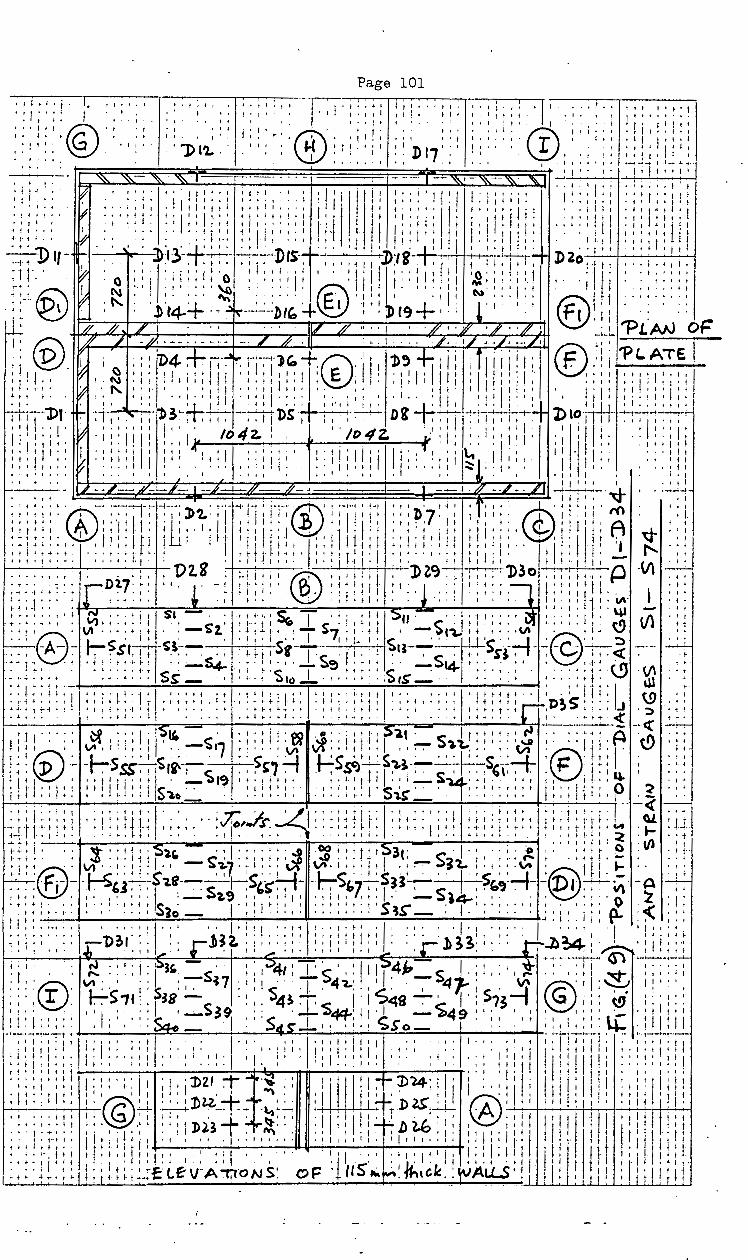
Page 101
I ' I • I ! ~ i ; I : 1 I -~, 1 t ' t ~ j i l 1 t I t • I 1
1 • tll + ! 0 • ~ '!" t t I ~ 4 1 .,. ' :: ·:···.: , .• : :::;~ '"' ill' 't ., ,, ' ' !'"''''' .. . .....
0 ... I • • ••• ··cv· ..... li.!~:!;
I I I j I I '"' I I j • I ' I ~ I • I I I I I I ! j • ~ ; I ; : ',' I 1 I I t ' I l
.. ~ 1'1. ' - ' I . ' 1-{ ' t I - • I ' I I J) I ' ' ' I : ' ' . ' I I I' I ' .v . j I' I j t l 7 I 1. 0 ! I 't t I I I I I
I I i o • I ' t • I I - I · : ; : : • ; : ! ~] : ·:-; r ;· · '• I •
"-"- "-"- ~ I r- - · · - - - I -~' "-"- ~- '- ~•'""'·__.,_,_....._.---i
:;i<. ? '::; ·; li!::: :!:~.··; :j' ~, J! :::!jll~jl:i;;;j: 'i:::!:i ,;:i:;:l: ... A .... It .. lti•t•l ,,,tt, .. , I I I'' t •••• ,, ''''I'll' ·lilt::: ~:l:'t
• 'I.'.' ~ .. ''I.' ''!''I''' I I'' t' I'' I I It I I' )1 I I I t I ''"''I 'I; I·· I'! ',~~.·-~_·::: I~ ':·~. :: :•.tt::: lti;::~: !i- ~ I 1::,:: ~t !':/l~lili '"" 1
1 ;::,::tll 17 I • ' • • •·. I ' I ' ' • I I ' ' I I I ' t l I I ' ' ' ' I ' . -. I I I t I . I I ' 1 ' l
' ' . :1'\ I ~ . ~· . ~·,.'l . ...1..:. I I ' . ' ' Dt~t ' ' ', I ·.'7\' • -1...!.. ' I I I I I . • • I ' ' ' ' • • • I I I ~.v 1- ~--....... ~.-~ . .;1-T.-;-:-: . ,
1• · ~-. --:~~.v:ti-~t.. 1 1 1 1,
1· I,, D2o 1 _, 1 , •• , ; • , , , •
~1 t·. · ~ 0 ; : 1 I :. i:::: ·a 1 : : : : , ·1
: ' • : J'11ll't:: : I : I ! 1 ·~; ; : 1; :.1 .. . . ,· ·j f ·1· ' ·':::::
H . @ I ..... ·-' I . ' ' • ' ' 'a . . . . ® t I ' I I I I ' fl.)' ' • ' ' ' ' .• ' ' ' I '
: :-:. . ~ . ~ : : • . +: .. ~ : . : . . + e·, . : :; . +. I ' : ' . ; : . ! . : ®I I ...... : : • ~-; ,
1
' \ ~ ' l r4- '-~~----bib 1 • (()
1 I i , ~~ ~ ,
-l-,. .r. // L 1 • 1v // .. · · 1 · // • • ·f" ·, · ·/}' ~~ ...;_:... r-LAN oF i ;· '1)\ 7" . / ~ ~iD· 4-•. + .. -~~ .. -~:.:, ~· " 0- -~- : . I']),. -L~,: : I /r·,- ·,/-,. : i--~~· ® ~ i 1: "PL. ATE I ! 1 ~- ~ I~ :': 'I :'; 1
1' :: l: I~~ ; ' I! ! .~~I l : I!! !. ::' • I'' I.''
:t!j,; •·"J ,j. ''''"''' ,,,., •. 1 'E I i· ·!·''lilt ·J,It•il· '"' ,.,;!,,., t I I i I !:.t . "' •• t· I ·' • I t I . I t I I ' t I t • 1 I . I t I ' I j I' l I I I I ' l I I l t I • I I ' ' !- t I t I tr" ! I I i I • t I . I I I I. . I I I I . . I • i ' ' 1 I I • 1 • • I I I ~ t I l • I I I t • I . I I ; I I I
, I, ; , , , +~ . 1 1 , , :j_ 1 •'1 1 1!, + t • I • I, • jlf 't' •' It' I
TI~-1 · -l>t r:- ·:T1 ..... , ; ib3~ .. ; ; . --~l>s trr;·~ Di . . t'--'-11 :-.,,, i, . l>l~ -:-:;1
-~~ I I i .. I' lA ' ' I 'I ' ' ; I 4 I ' ' 'I 4Z. ; I ' ' • I' ! I I - I I I l I ' ' ' I' l . 1 I ' ' f v ' I II I I II I I /() 2. I ' () • • I ' ' ' I I I I I ' ' I I' " ' ' ' I'
I I I t I ~ I • I I I I I ' . . I I ' ' I I ' I I I I I I I
f I . I ·t! l ' I . I 'I' j I ' I! I "I i 'I j I I I I ' I I ' j I ' II' ' 'II'' , I I I 1\.. I . I I I . I ' ' . I + 'I ' f i I' I I ' 1/ ' ' f I I I I I ' I ' ' ' ' ' I I I I I . I I I I ' : ' II I .... I " I ' I ' I ' ; I It : ~ : 1 : : : : v . I . I I • • • I I t I I I t • I , I I I ' + ~ I I I I I I . ~ I ' I I I I I I I ' I I I I ; I .. • • • • I I ; ' I • ' j I ' I j I • I ' I ' I . ~ • ' I I I I I • : ; :
_ _._,__,_. -·f----h"~·-/··1--§~ -/L- J9'-"-~~..J -·I J~ ~-"'··-' '1 '''----.J.. .. ~_.__.
I It . I I I' I ....... ! I
:; ::; :: · . - :--:-:71-:-~-: ),_: :T -1" 11 :-,T~ a\' r :-1-1
: r: ·::: n·7:,: : ::; ; @.;, . :, · 1'(\ ·: ,_
: ~- ; 11 : ~I : ; '! : 11 : i U· ' ' I f It :_ : i II : : l ® ' 11 I ' ! i i ; I : I ; .. ) : ' j
1 t' •. : ; I G:.. ; I II' ,. ; A ~ : ' : •t·····~tl''ifl j II !11 'I' l' ·•I 11 'I ''l'''l't I· ,,, . '1'1 t' '4 •• ·-'-·~····· •I ··•t- I I. I lit l"'i ·It ,, it •It ,,,,,, .• ,, .• ''I ........ ,
t t I ' t t ·• t · - • 1 · • • I · i r ~- f 1 I • I • ' t f 1 1 I I j 1 1 II • · • " t I I 1 ' ' I ' ' I - ' t 1 t t t- 1 t t .. ; I I • ; ' t. I ' . I I I 4 I I I . + I I 1 -i I ' I ' ' ' ~ t -! i I t ! •· I . I I -- ll\ ' t ! , .... ,,, . , ,;, 'V~8 :.:li•' ® ,,,,:it•' J)~~-:--.-r,--;-:-"'l)3o ,;,:i•1· {J, I~ . ,. . . . .... :r·Dl7· .. I I, ~ __ • _, +- ~ f i I a..: I i .. ,. I . , . ~ . I I., I. _, I I, I,,,, . I I , . .,., •• :., ... ,. ' . ~ •Ill .. V- ·:Ill I' .... : .,,.,. '''''I 1·, I •II
~ ~ ; ~ : : • : ' • • ' ' • • ' ' ' ' I . ' ' ' I • ' ' . ' ' ' ' . . ' ~ i : : ; : 1 : : ~- .!.. ' : ; ! ~:: ~:: · ~ ~.::.: 1 1 ss.-;. : ·; ;_; ;·; ~-- T s': 1. :_ ; ! ~, · ~·:I: 1'::: ·. ~ : . . :: 1: · ~ \ll ·;; ····e· Vl··i···+ .. -o%. :t:~:·.:' 7,:L·~~ c.;. -.ti[:to:>'~:+.s::~ ·©· :~·:) .. ~~-A-:- r.-~ic:TI- ~.~:~ .: qj,sr- 1 .. 1 j, ~ .u-:- . ,. sf:--,-~-C~<t ---1~ ~ --t -t ·t • t I 4 ~ ; ~ I + ._, ~ ! • .;_. 4 • t • ~ I · f • - s~ t t t- I t . • --S14- t • t • i- l t 1 ,t· J ~· n ! t
~ .. 1;:: · : ·:;::: ~·: Si _ · :: · ~ ·s,o J._ · . ·::::: .$,$ ___: · · :: ·::: : ·::::: t: ·v · ~ · ·: :;1~:~t; \"·· ~--~·~····· •t '''" .•• ,.,, •• ;,,~~··· •••• ,.,,Ht•··l; .:'lf1:j rn ,: .- r -t -1 , , t ~ I t • : -t L + · r t • t t ~ 1 , t ... , • -1. i. +- ll t , , ~ J ~ • 1 ' ' t · t ,. ~ , • , • t + t + + t rJ;1)2. S' ~ . t • J '-;! • ' '
'~;·,'t,1',"-l~•~ ',l,!l•l<l'''.:'.• '','','.,'~ !ft·tf-.,,1 •tf!,!~ll ·~•t •·t tlt·rtlt t ;I .~~•· ":> '1' + t t' 1--0 1-- ~I • I f j ·o t •.. f •' "~ If of I 0' j l 0 ·0· f"~ • < t t" •
1~. 'll;i;'• I _, - -<( I-'-:-. l .. . .. .~ ... I !""'' ' ' ' I ' ; I . C)Q '0' . ' ' ' ,. ' ~l.\ . l t t t ! I • ..... ' ' • ' " .. 1 l"\ . ' t
1 t- I - , , "l ; i , , , .... _t"" • , , , l .. liS -~. , 1- • 1 + ~ 1 _ s .... · 1 1 , . , • ~ 1 • . • t , 1 . r .. I\ , t .. t I J I· I \I' •• . 'I • I • 0)11 . ' ... ' \1\ Vl .• ' t' 't I •• ' • ~. I ' ' ' ~ '®' -t 'I' \;J 1!-; ~: (V :.. _Ls~,:..:_:_.s,d..-~. , . S" , _:_j ._~sre.~$,.~-:-~·. ~~ .. s, '-L , .,.. : lr ~: ; : ; : ' ... .v I. .»' l I .-' t:_ • '1 ,, ~ .1, ~--~ t 'I' ';. ~ 'h 'Q~ I T"" . 't.. ' ' .. ~ L ' 1 I I t t ~ t ! . t ~ ' - ~I, I t I I t f· t -t t • t. I 1 ~ t j J I .--.. ~~A t !" i ~ ' I ' t 1 I I· . ' .. ... . t .. :- ; -r , , 1 , 1 , , t 1 1 , • 1· S . , 1 ; t " . , , , , • 1 . l , S . . . . ....,.., . , , , • , , , j' . , j :- ' , 0 ~ . ,. ! +-·4 • I t ,_ t t 4 '" ~ • ~0 ' ' ' I ~ • J ' • I I • I t· ' ~~ - I . . I t • t • ~ ' t t I I • I . ~ ~- ' ..
I . . I - . . l ~~-+ t ·'·I .. i t t . ' ' . I I t • • ' . ..,.. ~ ~I . ' ' II t l . - . I • I ' ' ' I ' ' .. ' ' ' ' ' ' . 1 ' .. ' ' - . ' '
• , • t . • , , 1 , • 1 ' • ' t 1 , . . •. • vte w-r , , . , .. + j· ' , i , .. , •• , , t , : , , ' , 1 1 , , • ~-~ i . ~ , J r 1- t .... 1 ~ t- I f , I , + I ~ -+ ,· ~ • t + t .. • rO' .~- . . ... I -1 ... ~ . I . I •. t ,
1 , • , , .... I t t • j.. • • -t , t , t" , • • .... . ._ • __ _,
-i-t ~ . t t I ! • . < l t • ~ t I j • ' • + ' t ' I ' ' I • I I I I I . t • ' +- • I I • - ' . l . ' j t t· ! ~ • ~ • t --+- t·t ~-- . . . '~ 1 t I f: Vl f t +-"··-1· .. ~ •• ,J,."'l' ··l''"''·j .oo,,,t't'3t· -1•' •·1· -o , ..• ,,.a ·•1· ,_ ... , • • • ../) ••• 1 1 1 :-
1. • ,... • • , , , , 1 • . ~ •••. r· ~1 • . s., , . . ... '"'" , ... t ~ • - • , . ,
' • I '®' I \I\ .. I • ' I . ' ' - i:) 1,.:7 ' ... I ' • ' \1\' I • ' ' ' ' I :-- OJ 1.. I ' ' ' •• VI . I f I .... . . ' ' ' ,j,, .•• ·~ ,, I ''l__j LC''·''S ·I . ~··~ ''-1 '@ !- ., .~ ~- ·F;-- · r.-s,J~~
1
1-e---:-:-s 1-:S'"~- ·r.;)"7-~, 1 ~1~~--;:::s-' ~?,,- --Dr :--:-.....-~ -A'--;-:--
, ~ .. t- • , • I • , , • i _ 2.9 1 , •• , 1 1 • , : 1 1 It • I - ~4-, , . . , j •• " ~ • r 1
·t-'"'"t· ~· •.• ~.,~~~s. l'''lt-:1, .• ,,.,.,,s,.. . I,~,, .. ~,,. l·t· y -< ··~ t -t I ~ I I . • • . •• I • ~0 - j I I I I -1 ' I j. ' ' I I • • ~.;;) - I • I • • • • i I I I t t • n__ ' . ' I 'J 11 '. . • ...I,J,,Jf, \ ., t 1 1 ' .. ' ... , .. I ' . " ' i I " I ' ' I ' ' . I . I ' • I ' ' II ~ ' ' ' ' • ' ' ' • I . I " ' ' . I ... ' . I ' j ' ' ' I '
t•lt•l··· ~2.. 'I I 'l,~ 1 •.••tlj lttlltttt I··~' .,1, ,. ' :::l..__A l .,.,.,~ ., , 1 " .. , " ... , • • • • .-- Jl ~ ~ . ~ .. . • • . , • 1 •• , • • • • r .b ~ ::>. • . . . £r.1l ~ , . .....:-..... ._ ,
1 1 ••.•
. I ! I I ' . ~ ' ~ ~ I , . I .!.. . I : .,. • t .:.._' : I l I t I ~ :..__._ !I I ' ~I .,. --t· ~ ~,. G")--. -~ I ~ I t
t • I ~ : ' I ; I : IJ' s' . : I i .;}41 : I ' s ' I : I' I 14-" $ ' ; ! ' : I ; ,.. . : ; ' : : I :"'it : : ; : ; : : :: : ~: V\ ~· ' i : s : :-:- -17 : I : 1 s ' . T' 41 "L: . I ~ : -:- ~-r ; s ' ~ @G . I I : ~ I : ' . ' ' .. •\t..J· r:-tS7r .. 1 ~e-5 ·: •. ~!..,.< 1'17487~ 1·:.75~1 . 1:: ~ ::,·::: "' ' ' 'I I ' . ' I- 3~ '. '-'-~~,.,_,II 'I - l>AO. I!' ' I ' I'' I ·- . 'I I' I I l. ' I , ' " ' . , , , . <-- - I , , . S I .,..,...., r '"'l., . " ' ' . ' , " . ' ' ' I I' I ' , . ~~, •. , 1, ··.:>t:~-o- . ld.s----~~ ,,,1 -;;,$ 0 _ ·~~~,,, . ....,_·I , 1
r-;-;--;;;n; ,,,,;'''·I' . I''' ''-1'''1'1.''1 " ... ,,.,,II' ~.·,-r-1~: :· ~;.~--;-. I I 1 I i 4 I I I . . j I I • I I ' ' I I ~ I ' I I ' I I I I I I • ' I I ' . ' I I I I ' I ; t f 1 ~ ' f I I '. I' ' I I
'lil·i'•· I' •"•II" ti ''· '[ ;, '-'1 Ill'''· •!' ,., i•lt l''l!jl' •"I' 'JI ;:!!:;;:; f•• "I' '•" '' I., t" ' 'I .:; ~~:tl I:: 1: ";:·;:,; : :, : : ; : ,: : ; ! ; : : . ; : I : i ! : i l>ZI. +T .... -~ : : ' I ,. I Iii ! :~. J)"24-: ! J,· i : . : ll' I ~ ,, ll : II : ! ; : : ; I ! ~,· ll :::;;; ~;; ;~ .@1 ~r~l· :~~--t-,·::;~~ :: ., ~, 11 t:t~T~~~t; .®i:;; 1
[:; I i; i ; ; :;jf1 t~; • 1 • 1 • t- •• • , • " , 1 • , . . 1 v~~ . I'W\ . , , • . t ' u '-0 • 1 , , , I , , I 1 1 I !11 1 j • jt l 1 1 ! t I : · ~ ! ;. ~-i : : !f ~ ! : : i ! ~ 1 : ; : . : • : ;
1 · : I : :: : : • • :.1· ; · : : : 1
: ~ : ; ; ; : ; ; i i ~ l : I ! ! 1 H · q t : r: ll 1 1 ! i !-::~:;~::~ t:;it~;~-=-~tfV"A-:T;TONS~ c:>F' (tS,._~~~''"< rvALL..S·j jjl ! 1~1 ; n11;11
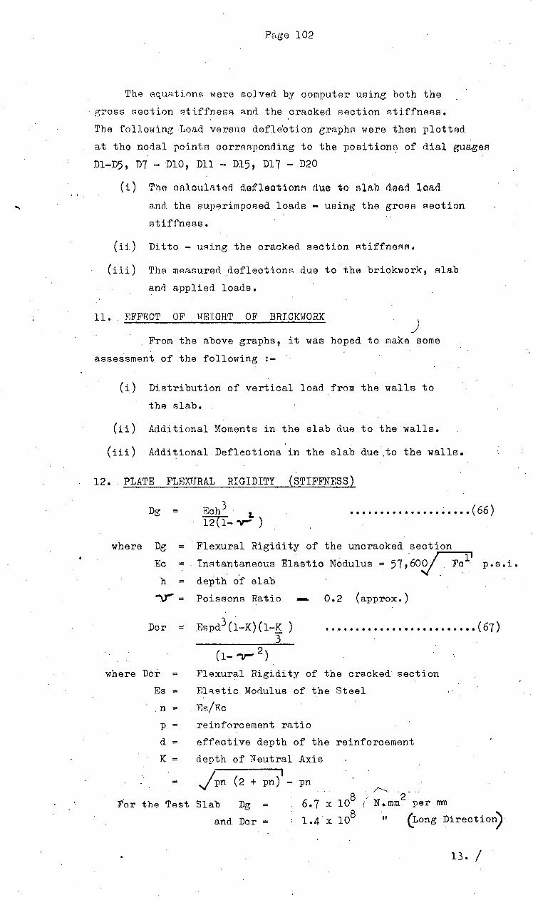
Pc-,.ge 102
The equai;irms i'lere solved by computAr using both the
· gross section stiffness A.nrl the cracked section r-;ti ffnees.
The folloNing Load versns defle'otion e;raphs w13re then plotted
at the nodal points oorrBsponding to the poei tion~ of d.ial guages
Dl-D5, D7- DlO, Dll - Dl5, Dl7- D20
(i) Tha oalcul~ta~ detleotionA due to Alab dead loBd
and the superimposed loads - using the gross Aeotion
stiffneAs.
(ii) Ditto - using the cracked section stiffnesA.
(iii) The mP.8.tmred. deflections due to the brickwork, slab
and applied loads.
11. EFFECT OF t<TETGHT OF BRICKWORK )
From the above graphs, it was hoped to make some
assessment of .the following :-
(i) Distribution of vertical load from the walls to
the slab.
( ii) ·Additional Moments in the slab due to the walls.
(iii) Additional Deflections in the slab due .to the walls.
12 •. PLATE FLEXURAL RIGIDI'l1Y (STIFFNESS)
Dg = 3 Ech 1. 12(1- "V""" )
............... ~ ..... (66)
where Dg
Ec = h =
Flexural Rigidity of the uncracked section
InAtant.aneous Elastic Modulus = 57 ,'6o~ p.s.i.
depth of slab
"\1' = Poissons Ratio - 0.2 (approx.)
Dcr Espd3 (1-K)(l-K ) 3
... • ..................•..•. ( 67)
where Dcr Flexural Rigidity of the cracked section
Es Elastic Modulus of the Steel
. n = . F::s/Bc
p reinforcement ratio
d = effective depth of the reinforcement
K =
=
depth of Neutral
Jpn (2 + pn)
For the Test Slab Dg =
Axis
pn /'-..... . - .
6.7 X 10⁸ - 2
1 N •. mm per mn
a.nd. Dcr = 1.4·x 108 '' (tong Direction)
13. I
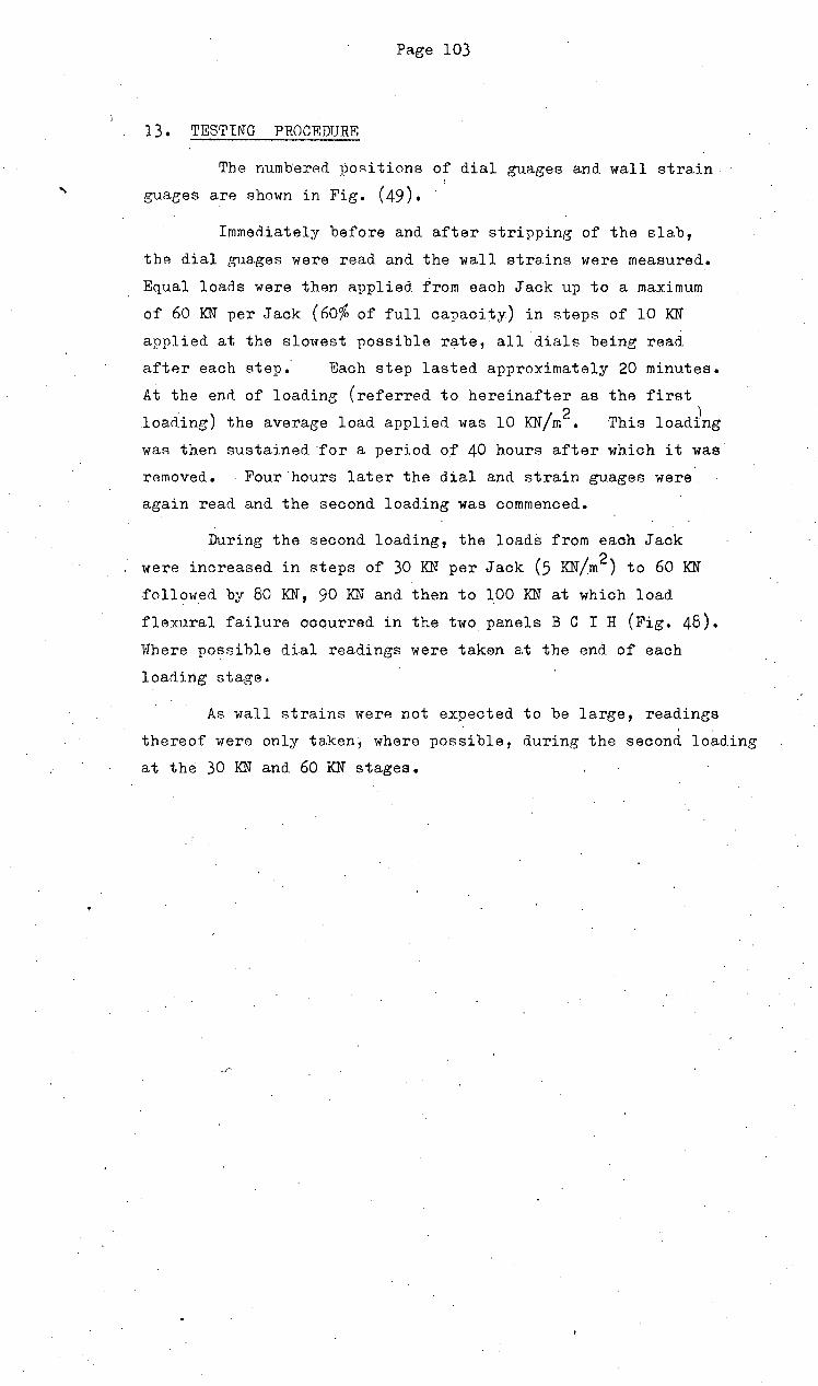
'
Page 103
13. TESTING PROCEDURE
The numbered I)ORi tions of dial guages and wall strain
guages are shown in Fig. (49). '
Immediately before and after stripping of the slab,
the dial gua.ges were read and the wall strains were measured.
Equal loads were then applied from each Jack up to a maximum
of 60 KN per Jack (6o% of full capacity) in steps of 10 KN
applied at the slowest possible r~te, all dials being read
after each step. Each step lasted approximately 20 minutes.
At the end of loading (referred to hereinafter as the first
loading) the average load applied was 10 KN/m2 • This load~ng waR then sustained for a period ot 40 hours after which it was
removed. Four hours later the dial and strain guages were.
again read and the second loading was commenced.
During the second. loading, the loads from each Jack
were increased. in steps of 30 KN per Jack (5 KN/m2 ) to 60 KN
.follo1ved by 80 KN, 90 KN and. then to 100 KN at which load
flexural failure occurred in the two panels B C I H (Fig. 48). Where possible dial readings were taken a.t the end of each
loading stage.
As wall strains were not expected. to be large, readings I .
thereof were only taken, where possible, during the second loading
at the 30 KN and 60 KN stages.

Page 104
'·
I.; R"RSULTS OF TF.STS
(a.)
(b)
·c a)
I '1. TESTS ON CONCRY.:TE SPECIMTt:NS (See Section 5)
The follm-tin:~ average rAsul'ts were obtainerl after 28 days.
(~ay of slab test).
Cube crushing (6 Ramples) - '5150 p.s.i. (35,4 MPa)
Cylin~er splitting (1 sample) 420 p.s.i. (2,9 MPa)
D;ynamic Modulus (3 samples) 6•
- 5,4 x 10 p.s.i.
From the above the Elastic Modulus 6 Eo = 4,4 x 10 p.s.i.
(30 000 MPa) \ .2. T"R':·TS ON 8mm DIA.M~TP.R ~W~"<:li:J, ROD SPECIMENS · -
Four specimens were tested and. had an average breaking
strength of 65,000 p.s.i. at a strain of about 20%.
Yield appeared to start at.:!: 52,000 p.s.i.- (360 MPa.).
and this stress was used in the Ultimate Moment Calculations
although it may have been conservative •
. 3. PREPARATION OF LOAD-DEFLECTION CURVES
Due to the large amount of work entaile.d curves were plotted
only for the following Dial gu.ages.
Dial Corresponding Nodes N Fieure
D9, Dl9 Average of Nl7 Nl8 50
bB, Dl8 Nl6 51
D5, Dl5 N30 52
D3, Dl3 Nl6 53
D4, Dl4 Average of Nl7 Nl8 54
D6, Dl6 Support E 55
DlO, D20 N2 56
Dl?· Nl4 57
Dl2 Nl4 58
D2l, D22, D23 Rotation wall D-G 59
·As the dials placed together in the left hand column
represented. similar Nodes, straight lines with the closest
fit were dra:wn through all. the points plotted for the
respective loadings. In general, both sets of points
were very close together in the first loading test, but
deviated slightly in the second loading test. It was
preferred to draw the graphs as a series of best fitting
straight lines rather than curves.
Only /

•' I
I'
'' 'I
I I I I
• I
-~:.7]· t • ; : ; ~ I ' .,
-·-loot-----+·-• l "1
'I ; ·f I ~
•·• I. I 11 t t ~ ' t ;
I' • I it I
r!.: ::. 9o -t· t i!. t • t t • .. ., .. t. t1;
+ ~:r!·
"' 8o I ~ t ~ I +I·.·
.J f. _J t·•., t I i-: t ..f f
~ t + , f··t 'I 1
~ 1 -'· . • .J •
~-7o· ~ + • I 1 ' t _, t· t-' .....
' f I t ' ! ; ; ~
HilJJ-i:;.~ • "t- _._ ~ j t ... t 1' .. t j :&g ' J .. i l +I
--~ -t-i- i t· ·I
t·· !_ ~ t t· ! ~ -t- t ' • I
: t ·;_ i -~- .; :!. ~ : ·ttt~~1~· ,.. 1- i 1 ~ i .., ' • I I ~ ! t
~t~~.to I f j I l I •
~ ;- r : ; , 1 f ~ ~ f f t .. :
~ ~ : r ·: ; ; ' ~ ~ f I
: ~ : ~ .: ~ '4o .. +- -i ; t ~
• t ! { ~ ~ '""1 " t t J ~ i t t i I
• 1 t J: L
' t i~ t I·
• ; rl-:--·~-·--'2.-
, t J I- .. IU ' 1 I ,_ _.1.
I I t-1
... t--+· t t. t t' ' ' . ' -.-;-..,.,...Jo .• r •. "
I,
''' ; -! t ,_ t--1 "'t 'I
• '' I I 'I
t I
'I I'
t.
•·
t I
I' I' . I
'.'
I I
'I
! I
, I
. '' I • ·I
'' It
. '
I I ~ I
I I ~ I
! ! I I I I
·j I
I I
1 I I
t j I! j I I I
I I
I I I 1
0 I
I I
'.
t /.;I' I 1 ,.,1.1 H I ~+ ·j· I
~ ~ : : ~· ! ; ; -~ I l!!
I'' 'I
I' I
I I' I
Page 105
I • I I-:--;;-:-.- -; -,7~-:: I I t I I I I
I I I I
'I 1
'I tIl I
I ! • (
11 I I
• I. I I
! • i j ' • ~
It 1 i . '
'I I I I
I I
I I I I
j
i'
I I I
I I If I I
I I J I I I'
I
I I!-.
'I t! j ,I I' I +" I j · l- I I
I I !
• -f I' t I I I
' 4 t'
'' 0 I
~~, 'I' I I I' I I
I I • I'
I I
I I I I
! I, I 1 I • I I ! I I
' ' I I I I I
If f I
---l I I I.
• I " ' '
I' I 1 I I
I I
I I ' ,, lltl liD
J t I
I' I t j I I I' t I I' I i !
I
I j If' I I
1 fIt t I
If jj! + ~ t ! ! ;
~ i ! I· I
t I I-
I!
I I I ~ ', 10 ! I I
i I I i I I I J I 1 I j l ' ' I
J!. l! ~:!it' 1; l!l; !· :-~. I i .. I' I 'I i ·+ 1·,,. I ' I I I. i l I I t ·i '
I l 1 J· 1' I I j i l i I ~ 1 . f I ! i ·
I' 1 i l j
j! I i Iff j
''It I
I I o
'I'
I I 1
~ ' I " i ,_ 1 1 I t i I · i ~ t- -.!
111
' ·I I t 1 ' I • j I
+ j l ~ ~ t
t f 'j t f
! • I t- • I 1 It
'
t -!I
'_ 11 i ' f 1 ~ 2
It': I t f
! ' ~ t ! t ~ I j t t t j
'j
'l '''

r---:--.-0'
'• I .. t
t I
'1 ; .
f-.
I'
o I
I 0
I I • I
'0
'I 'I
I •
I'
1 I
I I
Pa.ge 106
I'
- --- ---r'T ~
I
'0 o I '0
t I·
I i I o I
I l I o I I
t-! r! t
\ t I t" ~ t f I f. I I
0!
I l ! : ' :- ; ~ f f I 1 I It
t ~ t • I ._ 1
1 r • I I I. i: 1 t +
'"-j I
f'' I'
I''
f I j '0 1 I' t + 1 t
I' I
I'
'I
o I I
t • '
t -11 1
I· I
0
It
L : I
t I

1-' -,- -- -- ~ _ ... _ ------ ~.! -~-- ~- -- -
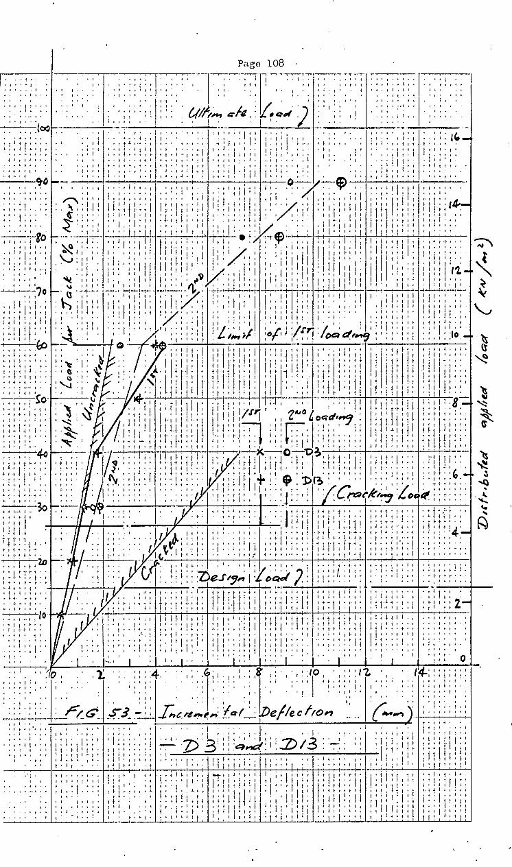
'I ' I t I
l·t I'
' ''
t I
It I I
I I I '1 I;. t
. ' t • I 1 I I
' ' j I
I • f I •
I' ! t ·t I It
.J ~ ! I ~ I i t t!' I I •• ~ t j I I j t
I I
J 1 I t t' t I , .. It I ! i.
• I t j I
I ~ I ' ' I ' l
t I< I l' t J ~ t
t '
Pa~e 108
I f; I I~~ I I r J I I I
I I I I I 1 ' L 1
I.
'''
j'
I
'' j
11A •1
I 1 I I I I
~ ljllj
'I' I I ' l! f f
' ''

--- --ro
·- · · ·- · 7o
-- . bO
-····So
· - · · lo
Pa~e 109
----~---(1-!J~~,.., Qlt { tJeul-.-~:,-2_..._ __
~--- .. ; ....
'-...J '.
~ i
" •. I
~ I
: ' ~ (J ';)
"-1
rs-
~~
:/
....... __ .,._ -·
. y( -. .. . . . : -.. -.: -- .. ~.- -·-- ... -+-- -.
...... ~ .......... - ·f
I I •
L,.vl ¥ ;u /DqQ',...S' ------- --------
. f.Ir . -- .. ~ - . - -+-- - .. - . -,
. . . I . ><
,, ~
J . ·• ... , - . - - - - - - . .....~ --o -- · o · l> r &t · · · - • • • · -- · - - - ~ -----+
I ' ~ I Cre~~~c,~,. ~~~} { ---· --f-74:..----· , _______ ___;,_ ___ .. -. -·.. .. '
1 ---~~~--· t•• t- ...... ~ ... -~~ -~ ......... ,-~·- •• ( I
0
-7)4 . ... . . . .. - - -..
I - ........... j
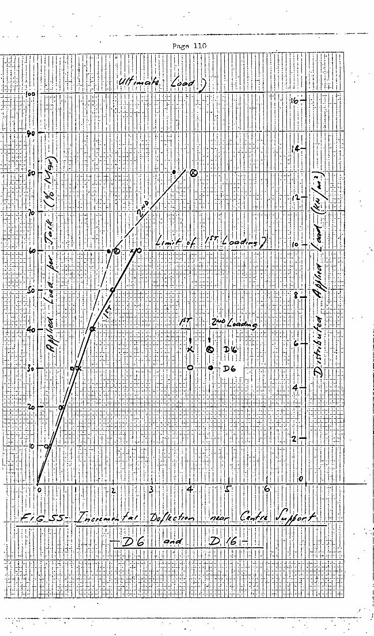
--·· -- __ ... ___ ..... _._ .... --.. ·------------------ ·----
.. _~ ... --·- --~--··-..-- . ·~-------:----: •• • • t
·,
. i ·j I I I •
\ •i
I
I I ' I·
I ..
-- ----~----------- )

'I
'I t • t t ~
I •
, I
I I
I
.. I
I 1
I'
1 I t. I
t.
1 I I ' It I
'.,_I l'
I' ~ t •
'I! t It
I' I
I •
• I
I' I
,, t l I
I I I
I • t I I I' t
I • I
't
I j
f I 1 ~
'.
I I
1 I I J ' j • ~ :
f f ;. t
t ~ t t I • I
I j i I' .. '
I I
I'
. ''
I •
I I t I I
' '.
• t
l)/0 I I
• It f I •
I I l t I • I
t. 't I I It
f f I 1
3
..-------- ..----·-----
. '. i'
I ; I I I
I I' t
I I'
i 1 i 1
I I I+ I' ! I r
't f I
I I
! I
I I
' It I • I
'I
I
• I I I I I
I I
' I •
I • t j.
I : I ~ II
I I . '
I I • I • I
'I . ' • I ' ' I
I
i l f t • I
I'' I'
·I I
'.
('.'
• t I .f. f-
'I I I i i ~ t ~ i t t i It; I
' • t ~
;. '. • r
'I
• I f ~ r I • t ~ I t
I ~ I I •! ~ 1 : : ~ I : t -+ ! t I
'. I I I •• t 'lj
I I I I
:1: II ~- t : : 1
I. t I ~ •
j I I t -t t I I t 1 I j I f It 1 I
+ ~ f t t I f
1: t '. '. I I
1 I I • • t I
I I I
' :I , I I I 'I '+
I
!I 411. ;(,_S II c; : ~ : : : • ; I j • f : I'~ ! ! : : ~ : ! : I : ::·?J~/_&d}~ tr~? ::
a,.t:(: • z>: 2o :f: {lfve.,..,.~~J '' .. ! t
t I I • f. t i
I j I 1· t I t + It I I If
:.1 I"'- I I t t: I
i i i f 1' IJ I
i j ~ I '
I I I I I •
I ,.I' 1 t r t j ~ l t I I I
+ t t I I 1
I I i I
1 iII I I 'I
'I
I t ~ t I
t'
'. • !
' ~ ·t
I l- ~ t t I ~ I f f I f
I' i 'f t I
I' I If I I I i
, 1 I!: i 'f . jl
'. t. i I
t I If
I I I
I I I ~ I ! ! I
! I
'I (I
'I • I I I
I' I ' .. . '
I'
• I l I I ~ t
• I t • I • t-' t l I
>- 1 I I ~ I I ! I It •.
t t 1" I 1 I
i fIt
I t .. I I I ' 1· I! I I I
I • ~ t t- •· I I
I I'' I I I t
I I I 1 I
'I: + 1 ,. ' I i
I I I·
I ~ t t ~ I t t I t 4 tIt- t
t' t I I I
• t I f t t
I I -1 t I t. t,.. + t t t
I ! I ,t f ' + t t ~ I t + I 1 I
1 It f I If f t I I t--4
t t t j '-t' ' ~ 1 t • i • ~ r
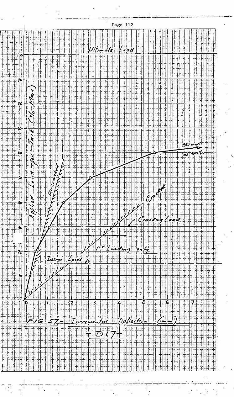
-- --·----- --- ____ .._--.... ~-----~-·---- -----------
\.
-- ·~--.- -----...---'- -~ ... --.,....._.--.-- ...

. -··---· ---:-----.---------,·---·-·-- .... -- --- --""'!" ___ ........
Pa~e 113
,.
I I
·I ' i I I
'
f· '
~
-!
I . I
I
I
! '-· I r i. I I. t
. I
I: --- ----~ ~-:---.-·.------·. -----.,.._-~- ~·------------ ------ ·' . .. .

~...- -·· ..---.--~--·- -~--. . .
-~-------·~·-------'---- ----
----.. ----

I Paee: 115j
Only incremental deflections due to the applied loadl'! from
the hydraulic jacks were plotterl, no account being taken of
the effects of the slab dead load, walls and loading girders
under the jacks.
From the computer print out of deflection in terms of
aa.4 the load versus deflection straight line graphs were D
drawn for both D e~ual to the gross section stiffness Dg
and the cracked section stiffness Dcr respectively. In
calculating Dcr, the average percentage of bottom reinforcement
in the entire panel width in the long direction was used
viz. p = 0.008. The ratio ][ is nearly e~ual to 5· Dcr
4. CORRECTIONS TO MEASURED DEFLECTIONS
(a). SETTLEMENT OF SUPPORT E
As shown from D6 and Dl6 (Figure 55) Support E settled
due to compression of the rubber pad. The settlement was
linear up to 60% of the failure load when it reached 2 mm: ·
AR the nettlementA of the other supports were small by
comparir:;on, the true ·deflection at any node, say Nl6, for
this load, would be less than that measured, by the deflection
of Nl6 when the node E is displaced 2mm by a concentrated ,
load applied at E to the panel supp.orted as before but not
at E • .- (See Figure 60)
Fi.c;. 60
Therefore apply /

-•
(b)
Therefore.apply unit load at E, calculate the relative
d.eflections everywhere by solving 32 Finite Difference
Bquations and apply corrections at all the nodes in ·
prot;ortion to the known value of WE
The steel ffirder supporting the hydraulic ,jacks as well
the ·steel framewol;'k to which all the-centre dials were
clamped viz. D3-D6, D8-D9, Dl3-Dl9, is a 18" X 7" R.S.J. with A. welded. bottom plate 11~11 x 1}" and. spanA 11 1 0".
(See Figure 61 below)
-,
~ td,
a a
t J:.i t ;2. cstQ"'e
'3!.t" ,:.,0 .. .~ &1 I II 3~ I " • l. , ... \0
()0 (J\
A _j p
~0' •ll)
~ -Oo ., - -· f ~ ~ Q Afl\
"" ~ x A
,_ .
RS.1 t'f J 1•
1. u~·l( 11-,; --J~~
se c.TtotJ.
1>. Fig. 61
Th1e to the jacking loads, an upward deflection was caused
at each hangar position which can be calculated. Hence. all
the dfal guages deflect upward by the same amount which should.
be deducted from the readings • This correction is also .. p~oportional to the jacking load.
The total correction to ea.ch dial rea.ding is therefore
·proportional to the applied load and if deducted would
only cau~e a rotation of the grap~ about the oriffin so as.
to re~1ce deflections. However, the graphs were not
corrected as the corrections were small and a.s the shape
of the graph was considered to be more significant than the
correct position.
,5. CRACKING LOAD
The elevation of the lonffer spans and the cross-section
at L/4

Page 117
at L/4 where the positive moment reaches a maxim1m, i~
shown in Figure 62.
p T/IC~
/r----------~1'~--------~
Fig. 62
If the Modulus of Rupture is taken as ~ p.s.i.
= 510 p.s.i. = 3,5 ,MPa
Mer = fZ =· 3,5 X l X 1440 X 632 = 3,34 Kn.m. 6
Less Moment due to slab dead load at L/4 = 9.Jj7 __ _
Net Moment = 2,77 ~.m
Moment <lue to P o, 18 PL
Therefore P = 7,4 KN
Cracking Load P = 4P = 29,6·KN = 30% Failure Load J
Similarly the cracking load at the support section is
approximately 14% of the failure load. The cracking
load for the bottom of the slab is shown on each graph
to a.Rsess the slab behaviour for loads less or greater
than the cracking load.
6. SLAB BBHAVIOUR
(a) FIRST LOADING
Out of the 14 central nodes investigated 50% deflected
according to the slab's uncracked stiffness for loads
up to 20% of the Fa.ilure load a.nrl 50% of nodes for loads
up to 40% of the Fai.lnre load, or nearly 7KN/m2 • The
changes in the slope at the 20% and 40% levels a.re due to
the spread of cracks throughout the slab particularly
near mid-span.· At the 60% level, P = 15 KN and the
total slab negative moment is
Page 118
M = 0,282 PL + 0,125 WL
= 0,282 X 15 X 2,085 + 0,125 X 1,5 X 1,440 :X: 2,085
2
10 KN.m
From the reinforcement provided
- Mult = 11,2 KN .m
Similarly the total slab positive moment ifl
M = 0,18 PL + 0,57 = 6,2 KN.m
and + Mult = 8,9 KN.m
Theoretically therefore, the steel of both Critical
Sections had nearly reached its elastic limit. This was
confirmed in the test as the slab had deflected elastically
at all the nodeA up to the 60% level (10 KN/m2).
(b) SBCOND LOADING
On removal of the load and re-loading to failure, the
slab initially behaved elastically at all the nodes, with
a constant stiffness at any nod.e, so that it reached a
.slightly SMALLER deflection than before at the 60% level.
In all cases except Dl7, the effective slab stiffness was
greater than the cracked section stiffness for loads less
than 75% of failure and in all oases for loads less than
60% which _in fact represents 75% of the design ultimate load.
As expected, for loads less than the cracking load, the
gross section stiffness can be used to predict short-term
deflections very closely.
With the load at 80%, deflections had increased non
elastically due to yield of ~he negative reinforcement
so that visible cracks occurred in the top surface over
the columns and parallel to BEH, and wider cracks in the
bottom surface on either side of and parallel to the
loaded areas nearest to supports. CFI. This concentration
of cracking in the region of the section having the maximum
positive moment, was accompanied by a concentration of
curvature, so that the slab distinctly folded in this
region from one edge to· the other. In other words,
a positive yield line had formed at this section.
A crack also formed in a wide arc around side column H.
At the 90% level, deflections increased further without
noticeablB increase in the ora.ok widths. Some of the guages
e.g. :D8, D9, DJ8, Dl9 lost contact with the slab and could
not be read further.
At the 100% level, fe.ilure commenced by spalling of the/

7
Page 119
the concrete in the top surface at the section of maximum
positive moment where the slab had earlier found a yield ltne.
A few minutes later a punching shAar failure occurred around
the rubber pad at B accompanied by a sharp crack.
Detail~ of these and other cracks in both surfaces which
occurred just before or at failure are shown in Fi~1res 63 I
and. 64. Note the conical or near conical crack patterne
aroun~ columns A, C and H.
For some inexplicable reason, deflection and cracking
were far more severe in panels B-C-I-H than in panels
B-A-G-H. This may be due to either variations in the
concrete quality or bond slip. Despite the heavy cracking
over the internal supports, the slab curvature was not
excessive and so a yield line had not yet formed there.
Consequently it would have been possible for the slab to
carry further load if shear failure had not.occurred but
this additional load wouid have been small as .shown later
iri the calculation of the Ultimate Load.
YTELD OF REINFORCEMENT AT COLUMN EDGE
This was· expected from theory to occur when the pane1··load
p . = - 4 ~~_y_:__ Log rb + 2,31-~
e Lx Lx
••••••••••• (55)
Mpy = 2 p.fy x 0,9d where p = reinforcement ratio over
the column.
Mpy = 2.9 X 360 X 0 2 ~ X ~82 = 10,4 KN · 75 X 48 )( 103
From (55) p = - 4,.. X 1024 ci 54 KN _§5.
Loge 2000 + 2,310 1,4
Deduct:weight of slab and girders = hl_ Applied Load per panel .
48 KN = . ,. . Although.Atrict speaking equation (55) only applies to
a uniformly loaded internal pa.nel, it was used as a
r6ugh guide to show that yielding at the column edge
would occur at loads ·near to the design ultimate load.
It was therefore anticipated and confirmed by the graphs.
that the /

- -..... ---- -·- -_ ... ,. ----- ·---·- -· - --I
Pago 120
. . !_; ~ , 'r' I rl , J 1/-' I ' f I , l''ll , I ' • lljl r~·TP Ill ! ..-ll I ,_ I .1' l . Ill I' I 11' ! ~ -~ \ \ I \ I t \ !.fi-Ut)! 11)/!11!: l,\1 1illfll!liil!i ''ll:!1! . ,J, I ,·IIi ili!H '111\ii : f_ I - L ;_ .1. I ! I I I ' I .. -I ' . . ! I . I I ' I ' I • I ' I . I I ! . I ! I I I I 1 . ' . I :i)j:i-Y:fil !:tdllliliLill]ill !!l\iii!ilil!i_;;:9?,~\1\l /illfllit I ~li!l!' !ll!t;Jtj
:.-..J.! .. J1·'+r' j'l··'.l··i.lll ~~·,lt·ij-1' ,l.1J.I'{.1f. ,.,,r.t:J-1@: 1.:-~~-,l·.~~ IJ''j''l:''·' IJ'III-j'· ,·!iJJI+: · ~.,. · .. n ~.. ~- ' 1-1 · · : ., 11·1 · t · · · I· · 1 • - · · -II · ~ 1· 1 · ' ' I · r 1 1 • lr! ·1-'···1 J::l!~-i-l~h LJ: :J-t~. j, .. ,: t j l l·j rl i ·.· ; i 1 ·.I 1._ r ,,_. -]~ . : I ~j I I!= ~t·l- J -~~,~ ... 11 l.l.l·jL~ \. t I· I ; ! !'L'.·.:=l.i I -· .. j ... l J·j- . _,_, I ' 1 1-1 .• ,I. I ljj 1-, . t I 1 ' . I "I -, 1 I. I·· I .... I.J I . ' ' . ··H·j . ··jJ· -1- -1-l-,- - . I .. •• I i • . I . ! i . : I : ' • . . . I i j ' • ' ' I ' . ! • . I ll L .• . • !. • ·-~-~ ~;..!.... r--
J .. ,-'-+1·- ,·+4)-; 7 ' . I l''ll' Ill' 'j .,!. I @U±LLJ .I . ·-' ~- 1-! I -1 -r · · · I : i ! · • I I • . J. I , ' · · I · · · · · ·· · I · · · -H·I H-=[-:,-: ·:-l-1' A . f I 'II: l i! I ! I I. ! II- 'T li I II!. I .jJ ,. ·1- . I!- j. i· .I,,-! ·! ... ~ II
ti-l-!-- +t-'- -~·-~--I l i J • -j ~-1 f '1'-l%lffi' , . . .I ,. t .1.1 .. ·u ,,,_ jl I ~- -,-~,- -~ 'I ·-11_,_, t ,_L- -~-~.,~-· II ~~-~-~ j.L! ..l.Li. __ 1_.J_ ~. . 1 .
1~ 1
1. .. . . I ~., .
1 _ . .. . . I . __ .. 1. __ .• _j_ .
1_ 1 , ~-~- +I r··i' +j+- -1- -' • - .. I I I .. j - : ' : I l ! I . .. I . '-1 . - . - . .. _, 1.. - ! I. .. _, .. I
I I . . . 1- I . . I ' . I . . .. . - . ' . . . - - . - I I ' ~ .. -+!-jt u.~ll .. j--~j--:-1-1 I· :1
1· .l:~illll [i ! ·I ·-t· ,.,1.1 -li-- 1,·11 .. 1-1'' 1··--j:J-I-1 ~-· ·- -- -~- -l -~- . -.- ~·.- j: • . . . . . . I • • • • I ~ , • I _,_ - , ' - - \ I j·-. I. .,., -L - . J .- - .. - - - - l I I I I I I . . .I - . ·I ' - ... ' .
- • - ! '· - - .• - . . .. I I • • I • • I • I· . ; 1~: j I _I . • . . I ! _,_j L -1-!l:· I. . I 11:..~ l ~ I I i !Ill: i ; _Pa.Jljjj_ I r: m ~-'1 Ill I i_~ I I :·1·'1 i I. r . f I i !
·lti.~~=~~=~~u t)ll·'.-~' i-J' IJ!.i~:i~,~~J-u H.i1lll!ll' 1'1lll ,.~,-~,~ .. In',,~''''". L·I'.,J--!~~1'' i-!-ll}l'--1'' J.,J _ _jj_l_ 1. ... 1.-·j- ~~- ··,· IJ 1!/:..._..JMJI.: ~-~~ ~~ ~~ 'J'~I. ·J'I !! I , .. IJ ,, . ---- -H- I .. 1.!. -- . .. , I 1 ~ ~· • Hr--.-T~: tl,, 'o 1 ~IQ6' _ • ! . , , :-: :i:-1+ ~ 1 J: - 1- J~-~~ -1· ··::11..- = j ·I 1 1-1 . :f. : 1 1 ' , · , ; i i l · .
1 . ·1 . I 1 ·h 1 I~ J f. 1 I I .
1 r: 1 1 1 : 1 ·1-l-~- . ~l - - -· .I I .. -.. I I I . - I . II ' I . . .I I . - .. I I . . J •. I I
,-,,h-1-H-1 il+1!dli ,lti-IJi, i,J/iJ[~ ~_,ll,d li ,JJil) +-1-1-I_UJjlllll I liH!'l -~.J'_I,_t.~'j_,_,t· :1 .. ,.,,,,=,~~~~~--~ li'll~-·~~~~~·:1~ J-ttliB,-,-:_1_1,~1-~-r.l,,~~ J', ~ 1·-!i·'·'~-----.~~--f~J-J,~-'.J'- ~~~.'; ,.,,.l··J·:,'!o~ '-- jji_l_ .. , ---~---·, _J ····-~· um'I''XL j:j. ~~-t ~ -- , ·'--··t-1 . --II - ....• I ~ + t j - I . -,· .. . . : .I . ·j- .I t -j-1• .. I I -. . . I· . . . ·I· - '+ . . I I I . ' I ,. - . 'N ·1: i-jl.: ,·.! lji,i:-!': .. 1 -Jt :11.,~ .. -~l=l·j·l·.,·t 1:1:~[ .. 1-.--l~lj-.t,l ·),l~-j ... :.- 'I~- It r.l:l_!-1-1:~
.. • . I I 'II I 'I ., .. J llllJf' ... , . ·' I - lill' I • .... ·j·l -., : . ,. -- .,. ' I ' l l.. . \ ~ . j • I • J 1 I . -~~- j ' I ' .. . . . I . . - - . • . • • • . ., . I I I I ' - I ,.. ~~-c;6~~~~ ~: ~: : . 1 -1-· ~ l+~!., J_~ 1' 1 _L~~m I . 1- -1. ~-~~~-~~-ill-:, H l ~ I • ' ' • ' . I . ' ~ I . I • I I .. I I -. ~- I . -··· . i . . . ~ -'l i I _,_ -' J I • . .11 I I I +j . I I ~~~.;:/~;.~~~~ !l1l~i·l::l!'~j-1--=1-~~-~-J:jtJ.l ~J-I-1J-j~~-==-I::I:':L':~ ·!· :·~J.L..~,, ·!lt·.EIJ· 1 --· , ·-· 1 .rc . ! .. . I 1 1. J .. . . ___ -1-'- _ I . _ . . •. __ . _ .. .. 1 .. _ . . 1 _ 1 • .t. 1 . _, ·l !.!+1-1-+ .. 1-~., 1. ! : ! • ~; ·-r i·' ~ ,, N'~- .t,. -~_1 1, f .,.1 .
1 , .. ~ .,. +L.f -!.·, J.-.1-t- __ ! 1 . ~,.i ..1 1 , ,, L , -.1~-~
i:1J±ITH+·:i_il~-l!·:l~1 :;;1' lit· I '*j~l++-ll II-.· II ~·=t-··+ ·tt .::::·11, l':·t .!il !.ll:j.j·. ·J~t=~j:t-i~J~: r-= -i®'-~ ~b.ilUJ I flt ~d l- J@'-~ :lt:n .~J.,- t l ,, .. ~ ~-i-ll i ; r i !_E .... @)'I ITI ;-;-.:i_ +J-L~-L I.-~ , B. . P) ,, f., . Irf-l- -~-~-, .. 1 .I ". J. I W-LU 1-:~i~,l- -t-~~~-- ·j-'-jl , I ~.,. r . . i ~-,·-; ---1 ..., ... _J_- .j •.. J ·I I V(: . . l" - -!- - -~- j . . . . I . - ' .. j I ' i I ,_J I +I++.!.~.~.-~ ..J.LI---r'·t··~ !·! : ~ 3; .. ,~-- 1-+~-- ··J I: r: ·t I ,_ I j t •...•• ~-~ , . I J , :I ' .... i ~~.: ··-·--rr--L J. ·t±t-J- .. -·, l- j ~... • . • t± -~-~··J- - f·t· - -.I . - • 1 . I . ·j -~ ·- l .. . , I h L I '-'· ... - ·I~ :+- .. t'-' t· . -,- .. . . . _l : ·-- ..... -- ... 1.. • - . -. • • . I : J. 1-. -·. ···i . I i ' : j I _LJ 1-1" .. 1 -;- ... L I ' ·1-- _ _j_l . - . -, I - -- + -. . I L,_ .. . . .. I J - • ·t - I I -· I. - I - _j_ .J. j ~J!:j)Jt ~+=l::':1JiJlJ ~f]~ l.! L' l-~l:l:l:lj.~h· _,:I·Jit~b-J-1-Ill.~·l ! I . -11-L J~J3J ·I i u. t·l_lj. ;I! ~,J,J ' .. !J:H+ .. \ + 1• !JJ-\:1~1·1 td 1J. 1 i-'1 1-i j • .1.+. 1 1.1 .,.-r --1-. +· _. , , , , 1 1 Jl1. 1 ; 1 .. -1- , 1 t i_,I_J 1• .i
I I ! ~~f!-t-~-.1. ! I ,·r , I I I I . i . I ! I I / . . ! . .:_t--:~' • I ~ I ·--· _1 I I I . I I 1
•-1-j-H-iiL + ·1-!i· I..!J-j-l-1 1-'J t-,·-1 ~ ~~~~! 'j'i l..t +- ! ·.~ I I !J I J'' : f. 10f.;-I I !'1'l f'-lj' I ' I ! II I I!· i I! i·' II +- ±J·- · · -r- ··l- .--1-- ··j -~- z. , f- -·-h·'· ·'-·~·- . I .t . J!4-7 . . - .. ' , '·, 1 .. 1 +·· ... I .•.. , ___ -- --'-• --1-1- ---··J .1 .. __ ,_.1_1 .. 1. --! --. - I•. •· ·- · ·~II -i · ·-1 tr-ffb-. -~ ~::1.- ~~~-~3. JJ l:r --1-=d.:l.l:li\! [I -j:J:!=tj.: :tJ :f-·t~t 1 .. ·j·1Jj.j·l·tl l.·j J-jJj,, ·;,. r.J 1 . t=! l~H-.t+t qlt· bf f' -1- ~+Jt· f-l_,_ --·r·ll I, t -1-- -J-J-1]- =!.} T'-f- ·I . 'I I r., I I ~I r •+j- ! ' I q! I lfi· i~l-t Ill
t'::i':1j :d:.cj· t :JJl- -j·-l -~-~~~ tj·lt·j tj -,It~~. ~i~ ~ t ! ~~h;t;=J' ;.,; .. , Jlc; l ;: f I'P.Vc. : I '·. i-!-- ·, : : : ' ' ; ! ; i.::- ~-iu~L. ;:! - - .1.1.1..- ·I -1-1-1- . ·- . -· . ...l.j. -1 I i -- - L. I I ,. I ' ........ ~~- • ..... .. # '-t··· I I I I ' • . I L ·I 1-,""-' I \ I I I I 1 J I I 1 I I I j I 1 1 ~ ...,..,.._., • j .... ,,.,.. I I I I , I 1
Lj-Llttt·\1- ·j·~-tH·J-jj· H· -l-1-lj ~: r j.l i I l·j·l I!\ .I ·t·t··t·t·j l .. , rm·-1.1 1.1 ·I 11!·J··I'_I.-t·l·· r j' . f. J ;-; I ,· -~ lttl·! .. H· .L '-t"l-l . .L .. -- ···--- t·j ,-'+'·-· ll]'l!··l·' Lj-jl.--. T't K -{····I ljll,,. ,j__lj" .L ~;-:-!-·'-=t··r-~--j·jt j··r'•··l ··i· II ·t·j·L-j-··· . 1 .. - ; .,·t 1-~ J! l'l!. jJ·I-' •... J. :~-,~·- ., - -·~.- -,-,· -~J . ·I ·I ·I . ' • ' . 1 I J! I . I I I ' . r· f I . . • ! •. r· I ' ' . l-'-1-' -, .. L. I ---_--···-----··-- t ,, I.·:-..: .. '~· I .,,. I 1 1~·-· 11'1'''1'' '+f-t--.-~-----r -·
11:--· ---1 ~ +·' . --': ........ ,,. .. . ..... , .. -. l'··I·J· 1 .... , ...... .. 1. . -r _ - - . -' ... L. . 1 . ; ~ . • : , 1 1 1 , , . . . 1 ; 1 , , , ~ 1 . r. i ;. . . . . · LJ-f-t:H.,+~· +-- f*t~-jl-fj K. : B I · 1
' • • '1 · tr;t • 1 1
1 , ~j-r I j· ' ' 1 llliill' j·li ~d I 1 ! ; · llt~ 1 j Jj ·-~ -·- '-ri- ·j _ _ . , ., . • ~ . j I ~ I r l, J·H .. t 11a :, , . . . . I •. , • • , r r . ,. 1 r I til t\1 1-.. ~ .. I .111 I lo I 1. ~,• 1
1
rf=f1±U-L ,_J 1-L! ). ,. , """"- . r'-J~-:-i!l-; . -. x· ·I J . • • ' ; i I J;ll.l I I I t I~ . ~ I : : ·'=f . r-~~±t:l=!·\~= j~-f ··-! ~ n t I If I . ' . I C\" i 11 ];(i'll"f'l~ =1- t-j~:J I~ !.L d ~'t.J i-B! ~; ; I j I ~~kj~ a~d~-I:i~.LiJ ~.~~t~·.lj:l.-1·1 n i1·; i-r-~ mt~· : Lj. i.1 :_ :l'·j=l=f=> ·I rtf: .:j~J··J·lJ ~I-· ·=t-J·J i i. Jl IJt=J]~~J~~IIL_,-_11 r I::J,i1IJ-,i_ I ~~J:~it.ll·t-1 ±_ -1-JJ ·1·1·1, ~·~--· ~ I ~~-------·! ·j .t ... ···j-··-. ..,---- t·-. 11~-~Jw···· 1--•-'-- ·· 1--'· 1 rl, ' .. ;f_ · .... } 1-· ·-------- ·I -----···- · · ' -•--tl --l-'J.L.! _ -·'r'' I ,, 1
1 l tj. :. !_f ... ,_1 . 1.Lf- .~l-··11. ... _-1 .. 1• __ ,J .... _, ··1,!, ,®. j, __ ,t I I I I I I .-!....., ~~ . ~~ ! I I I' ~ I· t 1 r I I I r I I I
LJ .. ! Ll .I . • I- ·I . ' I I . r- • • • I ;_ ' .. ,_ ,_ . ' .I . I I . ·H I j I i I .. J.J_; II I • • .!.1 j J:li1 : 1 1./-1-tjJ1@ltn~. ;It: It!!\ l:hj.jl ll·ll·l:ll l~'ll·! ·! !-!llt!l· ,T.I£~1:..~ LltlJ-11 ... 1-·1·1-·I·t ..• 1t11
r •.. ,,1. 1 r·~ .1.,,.1 •
1 .. 1t1J1· ~. 1 .1 .... ,M ....
1 .. ,~1=~J-1 ~ 1_,_tl-1 -~ -1~-th- -1-J-jt-·TL. .:,~. li :-·11 ·-~~-~--- __ , _, , l l lt. _,_ -'--- ·lj' J -j- .~_ ··-
~+j:li:ljj=C :.:i~ I~J·il,tl~ 1fll J,~l t t f!-trJ~l-,L~iJL •. ,-tJ. j= I@ 1:'1~-,~ lij··- ~-~l,-.lh~- ::j:l~,+~~i-j=~~~ ~. Ji~!JL~IiJ ~-! .. +. 1i-. ',h- -~-~--,j .H-,! -~~ ·1 !+ fl -~-fll .. tl· --H-.- .. :-,-. -li~rl i·l--~-~=~i-Hl-+ H+:·'l'=! 1,.!.!).1-l-j-'J- ,,~t··ll·tl·rl1!- 1 1 1 ,t .. l.
1
.. r 1 ~~~~ rn~ ~-~~j-1 1. i~~~~-·.1., Ll 1·-~~·,·t·,-j 1j·j·-1-t-~-~·--f:~
-;-f•-1·!1·· r!l.·'-!·t,-1 .. 1-t·.rj'·t--.J'I·tl· •-·- ---···.J--·' I -f·J- .i .... ~~-~--- ···j:·l·-~j .-; +·$·--~--) +j·J ! J , ' · ··- + 1· -··- · · 1 · I · • j· ~· · · · ·j·· · · ·1· · r· - I · 1 1
· f · · ··· - -- · · · · · · ·r· , .. - ··J· 1 - - T -- --- .:. L ;ttl .. , l-1··- -~ . .!I . I- I.- . -f- .. , ,.. . .. -- +-·· --'- ·+lrr-----J.J'1~lt--11j.1!11tl.J ::ll~!.\; 1• 1· •1· .. d~.l,' ., ,·:-1',-~!jll 1 ... -~-1 11r:· 11., -=~I· r,,,· ,r). 1-p.,J;=·t:~-:~~= -lJ-1-I 'I ·!r,l':lr ·'~'~" ~ .•... , :· ·!. ~~ ,, . I, ····~q ~~·,t·J:•· ·.+·r!-·--,+
~~~!,€t:..~Ji~~: 11 C::~1't:i:r ~ ·P4~t=tl'Aitj_lf4J: i dtJ7o7tJM l i_()/i; I I' J'~-~~: \:1 I l ~,-!= -~-~ I • t 111 ., 'J' i . I • II . . , ~
1 . I , . ,. 1· 1 • 1 1 r 1 J ,
1. ~~ . , ; , . ~ El ~~ 'j ,~*·~ ~- 1 ·- 1 -·- · I ·1 I ' ' · • • I '·· • r · · ·. . ' ' ' ' ' · I · · • · • · . · - t· - · .. - - ·· · · - - - ··
L ~p d! 1 r:J:t Lj. :J' ·t· ~! I r ;}.; -~ ~ i..-9 ,~! I:,&": ,4/i.· v:.P £_ ' . I ~·~ ~ L:l . ~.:-j. . T.::.: :L· . :j._J=d= =:=~=~= .= - _JLJ.L ..• L~ -j--1-l-t__,_J ---1 ... 1.. ,t. -·1 ... _r ... I-· _j_ -·------- LJ ___ ::j -
JH¥'-1. _ Lfi- .1 r.l_f .. 1 ~. 1- ).~. :-d-~. f ~- , .. t. , 1~. i , • .~ . ·'j;1~.~-J 1 . .~ ~.-- t -~ ~- - .1
...
1
. tl1.-l~-~ 1~.~ ~~~ - 1~~ f- -~-r-t- ~--1+J~J~ j~_ · t 1 c! .. - ·.Il-L- ·j ~- -~ /11 -1·1 111· II' 1 • l·j 1 · ~n -~-~ -1= ·· · -- - -- ·- · + 1· + -· !:!- -~-~-'--- 1- -·- -tl~ -f, ~-l \. ·n! t: t- fi-1-l=t -1 .~ :..fl; lrLI--.-1- ~:f :,.--j.:! -i - -~-~-- ·j -~~~=+---H~. ·t=!==f-i:T,=I· .=;.~-.= ·1+r. t-t-ll -. ·tJt:J=I.J. :'- 1-H=! +.1
1 ~-1- tl-lJl~· -t ~ +l:j~:j=.Jtl. ~J:- . =j-1= ~- J ~Yjtt~r-r t~':i=:fi:L{· ~~l=jJ~I='=H$ f~f!I~ J )_JJ~ t :.f= ~: f=~ _:!:..1':)- ~ =ti_~!-"1:- . Jl: :-- :1= t ~J ~ J -= :~:- = ~j= :}~1~=~~~ :1: ::.. ~1 ft~i~ :t: .1:ti ~~::!~J: ... 1_ ~-1·.{J_J 11 +- 1- .. [:tl + :ic;_- _[_f,+l1 ~-1-1-Y- d L -1+-' J H- 1 --~i= ~~- ll :r-iTij; l:i- J:l~::i:l1u l1-~--A
-: .. , ~-~-~l- :rf-t-1:,,. . .L lH-t=l. :L I '-t 1+!+ . -~- +.+ -.- -rt -1-- ll-H-H-1+1· Jfh:l~+ -1- .,.,.~= - t,-J.·:'JiJ' :_.J_: .L-. :.._: ____ J: ···:JT~J-~::..j·-'-~~~--= .1.:----.-:tt:.::t:::..~: :_c~.J.:1-- _-.:-
\
.;
r I
~
. I
-· - ···-- -·· .. -. ·------ ---- ------ ___ _:_ ____ --------· j . .

-- ____ r_ .. -· .. -·---------..---~----~-
Page 121 '
-H.-' +~-~--~+J-1. -~-~~--_,_J·_·J·j+~- lj_'_··j-1_~._,,_1_., ._.,.~.!- j·j·m~-j _l_j -''i_·J·-,-1 -~· -~- -~ - . -. -'~--~- ... ,._. 1'·1 .,-j, ']·~-~~-- -~-~-~- +1-l-lJ., !:It!·· -1:1-·J'--J-··t·l· ., -,I l·t--1.-r ·'. __ ,- ,_ ... , .. -·-·--- ·-----·,--,· ·····-,- ,----~-~--,.
=I~EI:,:,~f'f1 ~ :r h Tf(t -I- =
1·-,=! lt1~~ : = * {j·. -~11 ·"J ~ t(r · . ·. -= : ·: . : _ -·~ · . >- = .l--1 < ~ ~~ l :, ~ l)=l~ : tr
-j:!l'~tl ~~r ·J1:lt!Jl:! l~j'- "i"i'~)j·~t,= [-· ·!,ll-1-!J ~ 1 .- 1:: IJ1
1I·(.tl>: · ~ ~ .,. l -- · llJ· · .'{iTI ! ·~:,·,.fJ~·.l~ t 1:t: i
... u J .• :r.-!. .,~., 1-1 1+- . -,-'"J.:L±L .. , .. ·1- -.-. ,:u_ 1 +I 1 · · ' ' LL IJJJJ-lm _;~_,·J __ ,_+I ~-~· . 1 ~ 1 .: 1. :r-u
1·._,_,,._,,,·_;_,
1
.,,1 .,1
-:
1
--1 ... 1
p-r-, 1· ..... ,.~ _, .l.l' !l'lr~lf-ll 1 '!~.'~~1-'-' -]-1- -··-1-;·_J ··j·'- I ,,,,.1-·1-' .,.I . . ... ®I I I. I• - 'l· I 'I I 1'1 I' . - ' ' - ... - ., ·1 - . I· . .. I . . . I . . . . I I I I I I I I L. - - - - . • • . ·- f ,. I . -I . - - . - .. ! • • I ! I • • ., -):I:::I~:JJ {, !l!jjl.!i.l-1 i.ll l\l· .I,-, I .. IIi il .I !- -.. l!l, ,!\,-,!1;!. I ·jj·+ -l-1-'--·'1··-'-1 t+,~AI'!; J:illl 11 'j-!Jjl·i·!·i JJ"I"U 11 111 jll 11"1' -II .. , U.lUl_:l,· ;@~!'1-:-·-t+.- H, h·I\2./~-.J.~ · r _:1 ,·1· lj·1 1 . •_:;- JJJJl.~l • · ·- · · _ · j~ .l...:'='ll1J+ =J=l-~'-=j':l:l···_!~ J ·j:JIJ~:i.rl._I·.J j_·l· rH·.j:.l,-Lll_ : ~l~ :Lj ~ ·-,'+IJ -~1:1:_1 ·I:!:]~ .... ~l: .: : ·J· I' )- . ~~=. +~·-~: -1-_·J·- 1"-)-1'. !' II. 1,_ ... ' -f ·j:! ··~!~!---1---~---,··j· ·-~- I··-! ... , ... 1 .. --]-~- ·J···I- ....... ··- -· .. -il ···--· ........ , -·rj··-····j····-,---···'--·-·-!-1-1. u ··J-!-11 ·-····-- 1""1 , •••• ---·-·1 I· Jl. ----, I· .. I·- I·-·-···'-· -!- ------·-1--J-LI-,- -jf-·- !_~ --· ..... ,J ... :··-+--·-·-· . . --·-··-· +- ~----I·-'-· =~~~~,:I~J~·J.J :.\'ttl:l:l':l:l:l JitUI'··~= .. :t !+it I :·~~-~~-~=-!: =1--:t~~j'· .I i J:~-=: :c · -,-:-:: 1 ' I . ~-:- +r· -
1 ,ill_ l_=i_· !<:=!:~II: :11 -1--t-Lt--l-1-J •.•.... -.j-. -·-·· ILt-··----,-·j-·11•· --·J:l' ·-····- ,1! j·-, ~-, ~~~~ j_ l ..... Oi. --1· -;-h·J-,--,-J+- -···til'' - - ·- •·• , I'·· --+ !m, : ·· :· i ·1 , . . , . _ ~rfa-· -~-~- --mm ~l..r:l:i=l=': 1 :ttiJ··':'--'~U ·i:L:d·-~:~- :J::'.I.1:.J .1~: .. :_ .. :.1~ .:, 1 ~- • 111 ,' 1·::-! J=~=':f-1.:
:1:l:lj·':/:: ~~~ :!- =!=H:J:i, ,j :r_l.l: -l:l+j + -j-:IJ::: :j:':l: JI_L +: I~ IJIIIII' i tll,l: -! I=!= )1~:· j~11~J~~-~l: :1: :j= = 1
1'-J- =.-i l=IJ:!=~J{':!-~.: ~~-= 1~1·= = :1:: ~: --[~1~1:~ =: =!=: ~ ::
1::: ~~-~u1Jt ,,~!, ~ .·11! I· i) ll!.!l !=1 rE~= = ~uJ1~
T -j·LI-!-,-1- .. ·~-!-j· J·1J..·i' 1.11-J·j·[· "j .. _ _L -l··ii· -.-.--. 21·--.--- •·-- _, .,_£.:/)QdaHI fi'~:j/II"J jcol:j=. -L~~-~-1-~ .... L. •• 1- - ,_ .. -! ... 1. I .j. . . - - -'--- --- - -1-'- - .. L -- -j-- + .,. . ·t-,-j--- -l-1-
±·~_; ;_J:_~-l·l·l-··r: ,,: :{1 i_·r·~-! ~-~--1 ;_;_;·J-f-l-+1-~·-j·j~-j--1-I--\-J·~~-'--I-u1_~ __ :~--l-l·t·I~-V3-T-'-'-'-j_JJ .. ~~--~- it·j_Li~,_,_,_, -jt-ll::J-1-J_j_J_,_ :l-i-1 .,.,-,., j I ···1
- 1 ljj·ll-•··1-;-·'·j···~----··- '--j-J-1-. ·1···-···-. j ·--~--j .-'- !---t·'+·--1· , .... Ll.j-~1-J _, L .•.. ~ 1 .•. ; 1 11 .. ,1 ___ ,J. ______ , ____ L-j--··•-. ------·-- - ---- •I ·•·-----1-j- ·- ---'--·-_J'!·~Jl!fl.l)~!.d ; :::~: 1•---l·l· ·j·--'1.---t-- ~. 1 . 1 JuJ ______ L ,-' --lj- ~--.1 -11-j-Jj---' -j---~1+'--···Ye,.ilcN:I.J,i~Rtt~ t',r. ····-·1--J-j----··-· 1 --'-J-1. ---++I-·!--··· · · 1 ---l- -1 ·---·-L-1--.Lt.
1 1 '·I l ,jf'[· ..
1 1 ....
1 !· .:!.. ______ 1! .. -j- -----,I __ ! ••. - l __ L ____ J I .. !.L-t-~L
·I+- · . q .. :~ . 1 : , ·:-1 :-~ 1 .1 .1L -'-j+j-'·i··l- -1. +uli_._r_,_ -·--- ~- f-l-{ j·j-1-Lt1 ~ , 1-l-1-~-l~l~ 1..,.-1-J-'-)-r-LL -·· -0_/'_., .L .1 ~~.,.-·- , I . ·- I .. 1- 1_ ·rL .. --. : I I !- -1 j 1• ·II- ·j- ill· -- j' l.j'-j·· -I' ~ ·, .1.- +I --1-'-,+ -,-1-l-
.J 1..., 'j •.••. ,.,.1 I I I I· IZ1 I -j-L.! -~· -II' I i-: I'-~ l -. • • -' L~-. "' .... 1 I., .. L.,_ -t-1+ I ' , i I I , r f 1 ' ~ I ltf.4. I I I I I . ~- 1 ! '.....1.-+-4- -(!1:1:. l l I r I i 1 ! _ _1_ _! _1
. .LV;' '1,'/ 1_..-'l-t-j·~;-~! Jj' :; . -1: ~'II: ILl f i·lj~ I. j·l' 1.114·1 i! .: J·j ,~.r,_, ·-~-~ ·J-'j·Jj I j-jl I: fT!-l ··i-1 ucL1-j-tj-'-j-+ · t:/tf{Wn- , • . . . ·- I· . 1 . +· . - j . I · I .- . 1.1.- .I - . . - 1 - .I .I .. 1 LJ.-. . --. " l . ~ ·-L;
1
... -~-~ ... \ • . . ~- ! i 1 I ,. ~ 1- 1,·- [ , , -, .. 1
, t .. 1
..
1
®· j -r- .,. t- 1- -~-~-,-j-1 -1-' J. .,.~~, . _,. 1 -~~-~.~ ,_,_,_~_!_ .l·m'-••· T I .. L 1.1 .•. -- -'-, I·' ' . i ' ' . I . I •. L -1-'- . I I . . J_ I· I ' ' • ' '.I .,I I I j ., f! f- -1 , .. 1 •..• I.J- _L J_ +~!il+l .!-.-1-·lL! l -1!·!: 1 ·ii+i 1 l-ll··l· J _, I ,.I 'j 1 ! i 1·'.! ' 1 1,-lj---!--H+t+--r- -q/1,.., .. , ' .•. ·;::l,r ;::·;!,!·•·, I Jlll ,. ljjl 1- ' I. ~It!, ;-l,T··-L·--_. I I .. . +r-1-,1.' I I • • • ' '' . . 'I J -~ .. ,, t' ~·'I' I ••• I' • I:.~ ,_,_ ,,.1.- - -· _j_: '-·-•-!·· -·•· ·• '0' I I . ' ' !~ • ~ I • • . ·• .... ; .. ;1• : l @. I ' • ·•·--i-(+!-H~tl- +-I-!- - L TI ';:.I; I IJll!! 1-]l! I i ... HI :-t~ I' I I! I I H; j l I II::! ~·r-:- j __ · _:_)-4-.:JJ]:l=i-=t='jt r=l:!j-. B: , I ._:.;~·}.; · · ' '·I ' ! 1:1 1 I Til 1 I · ...;-;-.!iJ:'"' 1 I i i i.!. q' 1: 1 -H-'c! :· ,. _ 1 1 i to..~ ! ,_II _ct:l-'c ~=t~l~Jj-~lctJ ~ jj~~tltJ':J·lt%~:1.' ·-~~~j:Eif ::~:J:j·~ ::1~=~~---· _f!J~J-·J'~~i:~~~-=3'= = ~l=Fj~IJJ-j- .---·,~~~:l=j ij: J~~~:-_J, __ j··J:l1Jt!· l:j:J~~~lj-!:1lj:lJ±i: _!jj~+ -- _,_- -i-l--1~-L.~--'-- . 1- - _,_L~-. -~--- -mt·--- _,_ -'-- I+. _tt -~--,.,f.- ------ --1- -- -'- ~-~ ~-.- --- -j- ~ -I+J-~-r.. -[-- ·-- --f . + _u . 1...j.J_ ·t·l , .. - - ~ -~-- -- -. ·-j-- -1- - ------ - .. 1... ---.--. ·I --- :i· -· -- --'-- -- -~ - .LJ- - • - - - .LI.
1• J .. .LL ·-··•- . ·- _f_- ,_ • ~ - . . • - 1. _- - _ _ ·- . _ • - .• _. __ • • ___ • _ _ • _ - - L __ I..L :~H,:tr!tl:~tfl: ::b J:!-i" :!:!-i!i i~::- :.:!:, :~ :~~}!~.: ~JJt~r!--: :I: -.~:.:1=~ l}r"} , lj: :t/Jt
J±I*L:I=r~3.: :1:1~11~:1=1 rtli:t!-~~=' :ll~ijl~~-J: +·=~~··: : =l=f.J~ =1-ijjjJ'jj1=L = ~-tll_J: :jl±1: {lfjl=1~j~ :tJ: --J~:~t~--:1 __ -J-: j*l'~i~~ -?±B~J~~~~=1~:1'fr:E Jjr=,~t~tt Ji:
1
ffi-=J; ;t ~~ ~-1t~1( ~ = j~: ~~ ~~~=Jm. 3: =·: : = ~:~m®= :~:~-J-it!~~ ~J= ~l~1f~·= ·1·--~-JJ_·~---- --L •.. ..L~j-1--~-jj---i-- -- --·- -L-----'--1- -1--- .. .::I __ --··----~'1: __ j :i=L_ -;+~1-Hj~-j- ,J_j_ T --Ei -!+l·i··l-;-1-fJ_ J!- ,-r · +, f- .] -HJ- --l-1- + ,.j., · -t --ft~-lt-1.~- -l~j 1-- +H-l -! tl +1-i -.LH-LLi-H-~·- ~~-~1..1-tfl -1-'-'-l-i.J+i ~ j_~ 1-1-!Jl L'/:-'~t·J_.J~:.J-,-~- .L~--~·-~Aq//,,;.,,· + r-1·_,_,_,]" + '·J·l-ltJ-·J_j +. _aJJ.J_i .!_._._ '-·-·- -~-•-•- -· J.~··h ;~Of"l'l"?" /t:l(#- ··-- --1 I . ---·--'-L--j-----·-- ______ I...J _
tt•±J±u +· _ , -.- -H='- _ .. . t:-l.u.-~. T'-1- .. t ~ .. ' : .·-·· .1 1 .:.j -f·l :- 1 ; .1 . 1 :- -. J. -1- -t -1-'-lj· - .1. .. -1-;.-'- -}
1- -l :J_ -+- '··-+·-'-j -•- ---·-1---· .I:J+'-;-j--1-'- .1-:-! ~U-: -! i-1-'·\-,--., :-1 . "i\' -1-1-- •. .JT -·l --~--1.!--J·•- L -I -_.J ____ --1-j--- -1. j.J.J _____ 1.J_-j- _L, ____ --'--··. _1_1 __ L _ - --·t-------·--j-1- -·- '--H- -L
L 1=Li-J+J:1:1 ___ J_8fl-[ - 1 ~ 1 '-l-j:l.i.j_ .. f]-1~-J. -~-~~~-~lf- +jJ-'-1·]-t-fJ%1 ~~-~ l-_-1-jyl jili __ J_~L~?-1_ jt-J-,.LLLf ·'- -J·tJ~~-
~_.]_tTJ=t_.+ _t, __ ,_l 1'--1 ... ]-L.I ..• -, ·-•- ·"- ·-··-·-1-t··-U{i . ___ 1 - l1- .L J 1.1.:L ·-lj-1 .IJ.LL j-L--....1-LI--_J-J.J_L,_ ·j.::i- . ~-j- -L+: j- - ' .. ! .. -1-L.I _f U. - . Lj- --.!I -·~-,-·j• .. l I . l - . ' .!. I .J., '- .,_ - -L·± _J - .. ' --, - '; • j ! j-·j-1- _j.J_I.J_ -'-t-1-l-t-LL- . - _ _!_I_! _! ~· I : ! I I I .L l .l 1'- -'- _).1 ! -- . I . ! ~~~ ! ' J I I I - _!.._,. - ,' l:j ~· ·. 1·-- -1- .LLLj-j t j I , 1 I I I J I 1 I 1 I, r ! I : I · •• • I I J I J I
I I ± l j j I l I I J I Jl 0
'\o -~ " ' ·" on" -.C: •- ~-,·.. 1 ' 1 j 0 I I :tl=-.. •:;.• . - ' -~~ j~j ' --- ----- ... ----~--- .. '"" rttl-·--..&• _.,.,.,.,,_,.,.,"'_.. ,, .'· ,J '[~"ln. •! -==~-...;;:=-.J-i_ ,- j ___ L., _____ L 1... -'·-'- -~ ~- ;-•-'-1 j ..... -· • I _f.•_ .; ' ••. ! I . •'' ~-- 1--' L .1 . ____ j L1L _,_j ,J . .I_. LL:J--1-:Lt 1-·1+-'-+-1 _; __ _j- -----'-1---, ~~~·1--· · .. 1 . . n-LJ 1 p-~=tt~J=b: -ili~=~t~Lt,:r3. j:j:l:[~. ~~=~=~-~= ::r~Jt,_1 _~~~1-= ~ ='~-:1 ~-J~j: J Jr#
1
:j-l:::1: ~- ~~ :1·~·.:,:l:j='=l- J~-Jl- _ =\=lJ !=1 \=l~~== ±t ~~=rl-'-.. -1-t'- .. J.u 1-~-~-1- ._
1_,_- -+ 1. ~~*··-~~~-~ -!_-'-;· - ·j- 1- ~H,Jr -r- ·r· -·~j'-- -'-f·l------ ~j- -j-;· ·j· -1+ .· . -
1-, i-!-. -r·!t~~-!-·--1--l-- j-- -1- f __ J_ 1·-,- -1..--L ------!------- _J"-- ·- · ----1-·------1-1--·-•- ------·: ,-,-!-. j:J-·±1-·=L,. j- .l-l~r-1-}: I LJ_ . r· . J _~.,.1-1- - -1- .• lH--1 - - --j:j· ~:-' . --j- -~- -[- -f- . ·- -t- -1- .~- + - -~-'-- -- -~ .. ;·: J.J:1-~-J---1-->-1-'-J-·-- ·--1_ •• tl-LJ ·•··. -...l·t-1··· --1-- ----···-----1· I I _--i------- -------~---·-'--'-1·1-· @1 :)_r-iT
'I I ! I '....;.. J I I It' I I l I I'· 1 '1' I I I ' It I. : ~
L I - 1- -l.L ~ .!-1 ' i.! .! "":~. Lj-L!- '- ~ -'- _J_ -Li+-- __ .l ... '- _j_ .. "':i , __ LJ_- -LL -1- _j __ J_- - .. f_ ·- -1- ljl : - .L L ttt±tr:t{t: :r±!(d.-\:1 t-1:-.h; !-~-!-ll-l+l-!-h-1- =l-l-~-!-1-1-1 Hr.! :ll-JI ! ·-+I- -J-Il-J-t-1-- --1-41-1-J 1;1-! j ~~ =l=j= •-t-'+1_-1-1+- J:~-~-1~-I ' -j·-'- -~ -~'·-'-j~· -U·j·-i- j-'-- -jj]-l...L -~-~--~·-~_j_,_, ®: . i ·j· -t-1+ -l~- - ·t· -j-,'-1-~- -1. ··J·j~~- -1- 11j- ·]·j-l·'- -1= ·~. L ._,]. -'-· - • - - -r·j.J-·-[- -·- _, -1 .. 1-·-L -- -- -- -'- -- -~-1.- -1 , --- - -1 • - .. - - -J- --- -- -.. -·- . -- . -·- .. -- -L ---!---·· _ ....!---k- .. 1-L.L-l.!--l-.L H---.J--L-1., •. 1.1 -•j------1--------.:._- ··------·-·L!--·----l-l~~~-:':t:.fj· Jf-~-~--jj=i=J: :JJ~:':' :!:JJ!: J -Jj: :1=!= :1: :j=~~~~':l . . . _·: :j: + .::1:: ::- J: =J=l= .·: ~~-: -·: : ~ .. : J -1 :jJ:j: :j:lJ!:: 1- h-t!~l-l 1 1- -11-. IJi .1- -~-1-l-l !-1 -1- · + -- .1. =i-1· - -1+- - -ll- --1~·,-- + ~i+ --- -h- ·-- · -~ "1- -·- -l-1- ·- +I- .- -Lr 1~-=L:Jtl:l:l:l_ :1=1=1-J=!Jitj: ~~]~ ='= I ·j J_-1_:i:I~JJIJ/:- tj:!~ ··!- ·j'=- =J·: :I::~!,:~~-~- =j= ~ :j~ Ji: :1.: ~ ~~- =j=' +j- :. :: i}: :1: J~ J-j+l..·j~L.,.j ...
1--+·rj--l+-l ~--·11-~-'-ll· + -1--- ----··-· + ----·l-1-j-··· --j·:l-·--+--1--=1~·-
l,:.::l]=f,- :~-11: rt:l=j·j ·,··j= ~ :1 r~,:: .,u :. i: .:,:1=_:1-J -- ~,=,-,: ~ .. -- ~··: -:= .. -,·~1 _,. 1: :~- ~.,:!: =.·- -t -~: ::1:1~: :~-~~:: :-:: =l'=J'= -I- ---- j··· ·· -j--- -·- -1 - J __ - - · l- - 1· -1·· -1 1 --- · 1- · · ·- - · --I·-··· · - - ·· · ···r 1 1- - - ~----- -1- -··· - -- -1 I ,. - --I·.. + .,. .. '.1- ' - ··.- - ·• I -· I· I . - . . ··- - - ... -- - I I 1-11 I -- - - -- .. -,_j_t_ __ --~'·~· .. l/.!,. ~,- .. I. ILl I __ , ___ ,Ill''··~~ , ___ II _j_-1--:.n'l- L.-'- !j,:_:.,_A_..,I -----~--f:L H-H- +.·lni':~J f- 1~~· I· -.-C://?A..C.Ki--1-.PA.E~~"N .. I~ I :r. a,.-IT .~r.1 ~ !;,z. "~ r- · ---- -d- + ~j=~=J~:t:!:i=~=_Lj=i:i=::=l=}~j~ jtb~1'-::i~t-=~~~jj=jj=1 -;~r,·~ ~ ~--i:i;;;--1·=1· :i~ :j.=tt.=i_=~--~ i;=l= t_~=~=~=~--=~=l:: 1~=1·= =j=i~-:1:}~-~!=j=l=: J1:J:1t~tl:= t~r:l-!-t·l·!-j-1- ·~f·-'-'=f:r~-~ ~-l.l-1- -1" ·j-+ ~]_ -1- ±!-• . ·'JI·J-'+ I . l + ' ! I I..L.f- +~'-1-'-f-l-£- .. --1 j=j- -t __ ,_ . -d-1_L,_I~ffi=-t1 -l-·---1j_l_ .J- -~-!Jj_ :t-- j-- -l---.- -'--!- 1)1.;,.-- -j·;&._~• £jV/?~-~ . --- -~-•--- --.- --L- j_t_-- ---1- -t-- --+ -~-1
1- · -j-- ·[-1+: ·- ·- ·-- + -- -· -r • · i ~ ·,-.- -. , +: . ( ! • ···1 I I r· - ---- ·- -~--.-- -j- -r- I -.------!=J=~-,t·-=~j=!= =·If~': =H~-l!=!::t =t'=~=f:tJ.::d.~-j-1= =.~j~~~-_,_LI-tl~-l+H~J ~- ·J~J~- .,_ tl- -~- =1~~-l=rd:IJ-. -:r-::t::l+ =1~ =l='=l'=i=I~JJ!:.t~:~-$-- = .-1_1_ 1.1 i' •. - ··•--LJ. ·•-j _J.,-~-1. -- ·r-!j -·-1-- --. -•-··- - -· -···---L J .. ---1---1-- --. 1-L,_ --j--- .1-LL-1-j-'--'-' I 1 , I I I I 1 1 r I 1l I I 1 I I I I I I I -~ I I I I 1 I I
!-~-H-1·! 1-i·~- +J·t-+_·['-!·H-1- .j.l.l-!-t::r'-l-1-j- .I .. L -1-I·H·~=j·- -~~-~..:I.J~~-- ~- Jj:l -j-1-~-j-'- if'ili3 -L- 1~1-J -r- -tLj·±~-'- 1±'- ±f:.J.Jili+fJ+ 1,-,-l-·-::r---f-t-:- ,-1-,-j __ ,~.J---,+I·j-J·+I-·±· ------- ----·- c..j ______ 3~-------1-- -'-L+ -t- -r---t---~.J-rl ~-- -~-+--~·-, .. J--!-1--· ·- ~_ ·-·--·-' ,--·-- - -- ·--------1----- ---- ____ j ____ J.J.L. ___ _J __ t·±f-· ·-1-·-'---'- -------~--~--·' ---J·I-·-'- --- ±·-H--- ··-- --··--'-- --- - . _________ l_,_j_ L.l- -Lj.LLLf-- ·+·-- ----.l-·-·'·i-·-1- .---·- _,_J_ ___ - .J- _ _J - _J __ • -1-'-- -·- ---l--- -·-··---L 1-~;-~-f.:b:b?~ ~~-~-~1tJ1J-·T~r~ 1= :!t~ftffi= {jj~-1'-'= =~=t=.:-h=ill-- ::1~-'r::~~==rL1 ~-'=·= ~= =- = = = =m= :-i:l:l:m~=J~= T = J~JL1t~~J= ~ :d_: :li~~-f =l= ._i-f:~~-H-1-L ±J:- .J 4-- · -1:.1-L -l-1·~-l-.-J-,- Jj-p:-- · + J -d+ - :i~- -- · ++ ·-!~l*L!- _d:- :b::'cj-l~-H- Jj~j-rt=l~l j· -!=Fr+r-ii-1- .Lr- ~-t.,,- · -H- -n+ ·i- .- -;-1- +I-+ + ·f ·i-1-1· - +- · - -+!· -d:l·+ -F -+H+-i·l-t·i- -!-1-t 1-J~I-1· . -
• ..
1 ~ J
-"7"" ·-----.r--~-----------___., -~---.---- J

\4 do 0 ~
w Co 0 t-)
that the slab t.auld behave elastically up to nearly the
th~oretical failure load.
__ j8. PUNCHING STRENGTH
At column E the punchine sh~ar stren(5th i's giveri by
various investi(5ators as follows :-
A.C.I.
Fe' =
Tasker
= v u = 4b0d~ 4,120 p.s.i. ~= 0,45 PMa d·
v - 4 X 4 (150 +. 43) 43 X 0,45 = u
v = bd;-;;. [2,5 + rlO -] u . (d + 1)
= 4 X 150 X 43 X 0,45 +
=
10 [2,5 (1.'20 +
63 = 64 KN •
43 mm average
60 KN __.,.
1)] At the Ultimate Load in bending, the .reaction at column E
was 50 + 5 = 55 KN which is less than the shear capacity.
-- - ··1 _ _ __ \9. ULTIMATE LOAD .
From Yield-Line theory, a lm-ter bound for the ultimate load
Pu = 2P for flexural failure bi the yield-line pattern in
Fi(5ure 69.
l 'P "P 'P ~
L4
1.08~ 'l.o ll~
"'Po.scfce~t- · Y.c.t ct L,.,..t. (.b) L OQdt.., ;
lq~e cCt~ "'" ~ "'.t X '< X )(
·X -x X )
MCA., Yrefd a-... ct Ne<JCllhva Y•~td L •. ..e.. (e) S ecf,o...- c:rc::tclc:S
. Locttl.ct '"Po,,..ts.
(Q.) Pf~..., j
is given by /
'

\A Oo 0 N
L I
Page 123
is given by thR following Virtual-work equation :-
p r c 1 + 13
) + )2.:.. w r , M co'-. +~ ) + M ~
ul u2
Where oL == 'r;L tJ. = : f;3L '4)1."' 4
Therefore PL (1 - .?.~ ) ::: 4 M + M ~ 3/s WL .••••.. ·c 69) 1r ul u2
+ As = 11 no. 8mm,- As ::: 15 no. 8mm
+ M. . 550 X 360 X 0,9 X 50 X l0-6 +8,9 KN'.m ~\» = ul .
M . 750 X 360 X 0,9 X 46 10-6 11,2 KN'.rri u2 = X .. •
p (2,085) (0,964) = 4 X 8,9 + 11,2 - 3/8 X 4,5 X 2,09
p = 21,5 P = 2P = 43 KN u
Actual superimposed load at failure waB 49KN. The higher
f::dlure load may be d.ue to membrane action after yield or
the steel reaching a stress higher than its yielci stress
when the concrete failed in compression.
144 4-.....,. "Pos,f,re. Yutaf L...,ll$ 0 .J. I -, r J
·'~ ' )< . )(' k "Poc•h : L·~
-•'., ~~-' '
I. -· I Y. ~~ Nt~al,
!
~ L. ...
II t .. )( ' k' I '
- -·
•
(b) -(, """' I .
Fig. 70
For the Yield-Line pattern in Figure 70 a
the Ultimate Load is determined by a similar equation
·to (69) and is greater than 50KN.
+M 14 x·28,3 x 360 x 0,9 x 44 +5,7 KN.m ul
-M = 12 X 50 X 360 X 0,9 X 40 = -7,8 KN.m u2
This confirms the test result that failure will occur
according to the yield-line pattern in Figure 69.
As a matter of /

(R33)
Page 124
Ar:; a ma.tter of interest the Ultimate uniformly diotributed.
panel load was calculated by the following formula
(See Fie;. 70 b)
m = 2 ( j 1 ~· +1-fl + i 2 ) 2
+ .J.l "' where m = positive 7ield moment = 8,9 KN.m
il = 0 i2 = 112 = 1,25 L = 2,085 8,9
WL = Panel Load = 54KN including the dead of the slab.
load
1 10.. COMPUTED D"BFLECTIONS
The deflections at the principal nodes for
(a) Concentrated load at the quarter-points of eaoh panel
(b) Uniformly distributed load on each panel
are shown below in terms of vTL 2
D
where W = Total load per panel
L = Long Span
D c Slab stiffness per unit length
~n 18 f r h·
.>- 1- 1-4
1"7
'' !O
IS ' .
t1' t -t. J.-:-1 A
L 14 B
.'f'r 8 '-
J:
(a) Quarter Point Loads (b) Uniformly Distributed Load
= p WL2 Node A
2
14
15
16
Max. 17 OIIC--
18
30
(
o/.WL2 D
ol..
0.00337
0.00865
0.0105
0.0114
O.Oll6
0.0113
0.00482·
D
p 0.00332
0.00856
0.00905
0.0108
0.0108
0.0107
0.0044b
Contracy /

Page 125
Contrary to expectation the results are in good agreement
with a maximum error of 10%. However, it was surprising
to find that the maximum deflection occurs a.t Node 17
which is off the centre of, the Panel. The only possible
explanation is that the relatively closer spacing .of the
columns in the short direqtion stiffens the slab so much
that it approaches the behaviour of a slab on continuous
supports along AD ••••• BE ••• and CF , ••• In such a
case, the maximum deflection would be at Nl8 and so in the
plate the maximum deflection will be between the expected I
Nl6 and Nl8 i.~. towards.Nl7 as the resultsi .. ~~w.
:-- .. l , -~ _[11. .:.:M..:..OM~ENT.:;;:CJ .;.:;_,_V..;..;A~R;.;;;I;.;;.;]{~T.;;;.I O..:..N;_S~A:;..:;.C.:;;:R_O~S.;_S;__:;T=H;.;;;;E_P;;...;A.;;;.N....;E;.:;;L;,.._;.;.W.;..;.IDT~H
From the. Finite Difference Equations for the deflections
at Nodes 1 - 31 due to a total of 8qa2 in each panel
(Figure 48), the deflections were solved by the Computer
in terms of qa4ID. These are shown on page 124 -2 I 2 For a panel load of 10 KN, q = 10 N mm q ., 354mm.
The Bending Moments M or M were then calculated by X y
slide-~1le, at the Nodes on the critical sections, using
the following.operators:~
My=
J) --
t ·~-=-o, 2.
~~)(
(R. 4, 20)
The Bending Moments were plotted and smooth curves were
drawn. (See Figures 71, 72). Positive and Negative
moments My were then compared with the two alternative
step-function approximations recommended in Section F.
For the two-span condition below tbe'moments obtained (Fig.73)
were +M = 0,18 PL
-M = 0,282 PL (no reduction)
By integrating I
\.
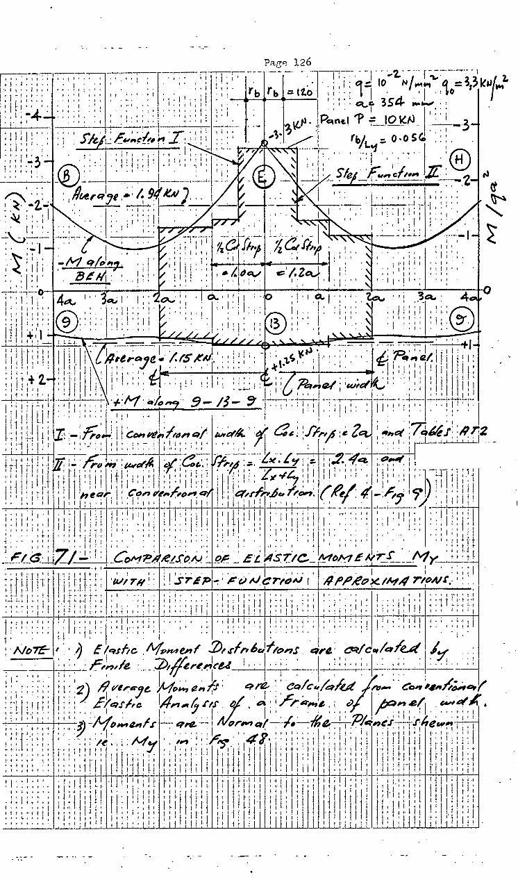
I I I It
• ,. I I I I
l t''. I j I I I I'
I: I l I! i! I
:I::: I
• j I •. It! I 1 I
' 'I' I 1 l •

Pa.ee 127 . • 1 • I'.'"; I I ::.;. r-:-:-TTT-~-:-: -~-:-. I''.; '1~-~~,-,-~-, I. 'I; ll :liT I II;:: l I. ' •• I.'.
I ' I j ~ I I I ; I • ' I~ ~ I I ' ! I I 1 I f t • 0 I I I . ' •• I I I I • I . I I ~ f 1 I' I ! I I • I I • l I l . ~ . ·• • •• •I•• .... t lit!'j "•llj"' • , ... ''111 1 1 I •l•f''''' ll·'llj• • ,. ' •. " •• ;. I : • • 0' ' I' I! lj' . ! I ' ': '! I I ''·jl I,.,.,' II I :''I' I {. ' ' I • '1. t 1 I.-~ J .... J! i I I It I' I I ' I • It I I I' 'I I I I'' . i I+ l ... • • I • .. ·(C) I • I :"l ' I ,.,, I • I I ' ' ' I ' I • I • ' ' ' ' I ' 'I " I I I • • I • : 'I I ' ' . j ~ I I 0 • • f I • • I l : I. • : • I ~ . j l . I I I t i f I I 0 I i I I : ! . I I I • ! I t l , , 11 : f"\ 'j' •, l !' I . ,,, 1 ,. I , 1 o • ....._. !all lj J 1'1\'•' '''''''' , : 1 , : . , ......, , : I l • • . ; 1 , 1 o I • \ ! , • , • • ; .. r- ~I '~-W- ..J_jj ' : : : I I I I j '
0
. I I : : : I ' ~ I I ' . I' ' 'I\. ' ' ' •. I 0 I~ l ' ' .... I ' ; ' . ' ~ i I I i ; ,. I I I l • I I . I ' ; I I • : , . , i j l, ' I •• , ' 1 I . . ' , , . . . . I • : . ..._· f ~ . . . . . I ' II ' ~ r I I l' I r: I I •• , , , , , IVt.. . . . • • , N· . . '. . , • , . 1 , • r " \ · J' 1 • • • I 1 • 1 , I 1 I 1
" I , .... ,;·t;j·• .. ,:~l'fl ......... ;··•i.·l l ,,.(AI f/ IJ'.: lilt 1,'' II jltjt¥
I •• j I I • • • ' 'j . ; I ' ..... ',.' 'I ' • ' • I ' . ...., "'' • ' t I I I 'I I . I I ' ' • ' I I I " t' I' •• f J ',, •••• ,., ''j ,-1 II. I~ ... ' • I. t I jl I I' I I I' I' jl' I II . j I ~ ·t I ~ : t" ~ 0 • : I 1 . ' ~ • I I I • /· , • '-:. • • ' • ! I ' ! I ' ' I I I t ~ I t I ~ 1 I : I t ' ··--ll•->tl••' ·"·I' II. ., :,) ~. ·~··''''''!I'll'"' '·l•ll II • • 1! ~! 1 • :__tO;)~--'::::_~ , ,i_...._ ~~- 'e \'~-VI lJ. .~ t t 'l, _j_~,:..J.. .'I 1 1,: I • 1
. : I . : I • i '\::..) ' • ' . . ' . '-' \.. "'J ~I\.' ' "'I ' . I ' I ' ' : I : I ' : .. .. . I i ! I : i I •
; : i j' j·: II i.' ; . . : i : .. . I : • : . " - ~-: ~-: \: "":"' ! ~- • : . I I t II J ; 1 i I . I ' i ' . I : . ; ; l : : I ~ : \tJ t' lji .. :.ill • 1 • 11']' li:l ' .. , j1 ''"l' .• ,j,.,,l ! : !' jjll li ' .j 1 • -I .... j • I • ' J ~ I . I I - i l j ~ • I . ., v. : . I • • • ~ I I I I ~ I I • I t ! I I t t ' ''J'f"i" ·!'•• "·I'' It! \,! •\ , I' •' . '•jt'l ~ , .. I• • '''J' ~ : ; j j J ~..J ' !@: ' . ; ~ II : ~ l !. l : i ; : J' " ' ' '.J \ : ; I : : ' ' ·@. ' ; i -1 I I ~ ; !~:' : . ~ ; : t-' : i \ j,; -1 : : l I 1 ' i I l • ~ • I ' 1 • I .. I ' I I t l \r . ....w-;.. ' ' . ~ I I • ' I •• ' ~ ,. ' ' ' ! ' I ' I 1 • "iil\['1-,-• ··"-.;_tli't:-:-;:- j11il !Ji \ "",·-:·t -...._,: ...._--~:IIJ!i-~~---~-l-:-;--~·:;1;;.,_: •.• f'l : I I : . I I t ' ; I '-I I I ' 1 I . ' '' ' .v. ~· I I I I l I .. ' 1 ' I' . t I : :
' : : 1'1 I 11 I ; ; : : i 'j 't! l ~ i ,-'11 1 : l; i \ ( : :' ' . l : i t ' . : : ; ll I : I i' : : ·~ . ' ht ·; ; i 11 ; I
• I! j ,_j 1'·· I.: f I . j. ~. l I : II .. ~ : ; . :. ; I ....... 0'! I': I •I • ! ! ' I. ' I. ~II' J I I ~ 1 1 '-1-j I I • ' ' I j I ·" i 1 l I I 11 '\; 1\ • ' . " ' I I 1' " " I I I ' . • ' . "'' I • ~ ' I I j I I I -~ ' t ; f • • I I ' • I l . t ! l I I I I . ~ I ' . ' ' ' ~ ct N . ' ~ I • I • I . b.. : ; ' ' I I -' I l
~:::;:-:. :®·\\0-~\t~--l·;!: ~~_;_:~'~ ;)_,_'ll! ____ ._:'-11·~: .. ltliJ~.:.~~-1~ 'l!:lJ.J; ~ . I I It I . . ' I J I t'' ' I 1 1'' I I • I' • 1\ • ~-' I I l "' ' - I f I f\ I 'I I ~·: <. I • ., 1- I ·
1 J' • I • ' I . J j I I I ' I f I . 1 I I I I I ' ! \ • • . I ' < I • ' I I ,. I I~ ' ' . . \) 1 I I I 1 I
: : ; ; l i ·f-j 1 I ; ; : : 1 : : ~' l I • • I .. ; () ~ ' : \ ' : I l .... I I . : ; : : : : I ! ; I '": ~ ~ . t ; II ! : I " : l : 11 J I i I : : : : Jj l ; : (~~ I h ; j I ; I • ' ~1\ :. : ,. ' ' I I )..'-; . ; j
1 11 : ' '1l'1 ! ,· ,. I ~ : \\.~. : : '(f Ll:.-,,· I. '! !
~!Jl ·jjl :@ .... j:: n1·.-.· :1::· i::~ I' i" 1: ;::j. @ .. :, 1 !1 li1\'~~ ~ :'C\'.:I:; .. i ' ., iII I-~- I •••. 1\~-~ k+w---- l N' :'1 ..i_;_ ~_._._l_j_ -,9' ~KL .-":._~:_~;I: f I •·I
~ I ; ' Ill I I . ; I • I ,. . ' ' •. ~ I i I I "" I . ' ' ' I I I I ; I I ' I j J I' I ., ., \:. I l kl 11 II I I I ~'fl-·'·1 , .. ,:i · '\.i··a. 'ii/' ''II: 1 ·I.: rl 1~11 1 ~ '' '1,~~:1 ~:~:.u;.'1 .:: 1~~~~ !111.· II;)!':'! ' ;' :; ·.·,,,~,; ,:;1 !j
1' · 1 :. :: ~'1 1;1jl, I\."': . J l ' l j I ' ' • • I ... • ' I t i • • ('If • ' 1\. t I • ' ' • ' " ' I I • I t '11 I I (\ \ . . I t • I j I I .,
I .... i L.' - l' I . " . I~.... ' I :.: ' ' ' • • I' I I I • ' • ' ' ' • ' : : : I ' I . ' "'t : . ' ! I • • I I • ljJI. i ...... , • "' :!' .. ·:.·I'' ,,~, ·m·' .. ,~,~
I t··•·· '® . I J ... ,. '11 ''"'&..'I' ' ' 11 ... 1-•1 -~-· 1·: :! I ~- __ N '-~__:_:_ ~ "~!\-_;_ .)~" t- -- ~-.J-- I I I ll.L..~' L -<- I i : I ' . I I I
•• 1 ' :.j ; ' ~ I . . ' ' ~,-: 11 ' l . \): ; . : \ .. I ' (V ltft i i' I I ~I • A I : '!ol~ ' ' . 1 'J
I t ' l ' ' . 1 , , . . . . ; , , . h ' II I , ' ' ! • t I a . . I I i I ' : ' ! I ~~ , ~ ' I i ~ : • . j ' I a- . I • ·J I " . <. ' . ' I • I I • I ' I ' ~ j ' . i • I • I .. I I &.' I . I CL. I I I ·~' d t j I I ' ' <U I V' ""' ' 1'1 ' ' I 1 I -I I I "· 0' ! • • ' i-' ; ' I : I .... ,I "' 1 ; • ' -~~ • 1 1 , ·':;''1 ............ l'·' ' ,,. 'I"'"''' -,;;.~· ·:. 111 "·•- ,~, .. "·II
• , .. • 4 • 1 • ,'Q- 00 : ~ · -~ ' 1' • • t-1 < I 1- '(' • cw 1 • t I ' • I • 'V I I • • o I j ~·-1 1 •·::•, ,:,· •• ·• ,., l-111-11'- ~ •' "'I 1: lit• · • · ,; · •:: . ' I .. • • ! l • a '~. . ' , I I l I ' / ' I f ' 1 ' • I\.._ I U 1~ I ' I 1' I li J ~ ~ ~ (' ~ • I . 4 J
: ~ · .~ Z:::~ , ~": · ~ { ·" ··' t-1 :~) ; ·, : r .:..~->-i-!-~~"~.:J+ ;~:f•:·;ij' ;1;;;;:. ~-:; ·;:.:i::' i~ ~!-:\ : .~:t;l ~:~ 1:-1
11 ... ·\t: :i ~ :\,~"1Jl l·t t- I I ; j 1 r -1 : : ! 1 " 1 t t-- ' • 1 I
1 L.' · · t 1 1
• 1·1 ' ' ; ..; ! ( t 1· I 1 ' i \- ; I , ' 1 ' '- : ' · 1 i'' ~ J i'
• + 1 " 1· r t ~ 1 • • : " 1 "' • ,~ ~' ~ • ' 11- ., , ~ 1 1 1 • . • , , 1 ·~· ,...! , . , . 1 , .•.•. ] .. '1''l't - ,-1 1-,1 1, .... , '·" '!''i' ·I'·'' to~ '1"1- .,~ 1j:· "j ·. 1 ,· .,,.,, ' 1 " I • I J I ~ 1 j ' t 1 ' : • ~ ,... . ' ' I ! I ' . : ~ "'-J ' 1111 I I I I I I ' . ' I ; ' •• I ,.
-+-~ r 1 -~ -t • t t r " :)/,' , • J , • f\..~ ~ f, 1 -+ • • , 0 1 , ' 1 1 , : , • t t . 1 , ~ •• ,. , : • ,
tl1;•·l1], 11''••'· •:t·~·· 1' \>i! ·'•·•:..._ • • ;.11 :1·· tl·'' .a il ·i•,.!rj· ' ••• • . •- 1 • , • 1 • 1 • ' • "' .•. ~ , , , • (f. , . 4 • , 1 • • - r 1 , 1 , 1 • ' 1 1 , ' • • \) • , " • 1
~.il: ··':Jti .1l ~~~~~--r;-t\.t-~,~ .:~: .... ,. ;. ~~~~~~ 11~--rL-! ~:~~--~~~~"~~t , I • ' - • I ' I ' I • ' ' ' I .. , ... ~ . ' ' 1 . I ~ • -:..J-0- 1 I I ' l . ; j I ' ()· . " I • "· ' •• I I+
J i 't ' .• I J I ' ' I • ~ • : ' I ' \:.:' I i I ~· ' ! ~ ' ! . . • : •• 1- .• 1 . I ' .: ' • ! I . tj: L i . ' . 1 ' i • f • J" , .... i ."' 1 l J •••• .f I , i J + t J ~ , t ~ t • . I • ; : ! .1. ' l. I·~· ! ~~ • J ,. L, , t ! r·1' . , t- j ' ...... , .• . :-. ..ii) . , .... r L ~...., I ._- : , 1'
1 , -1 • : • , . , • I I +- 1 .
1 ~ ~. .- , I 1 • t , .• ,
1 . ! . 1 . 1 , + 1 .
. ;;.;~.l-; :· .!j;-J J:;;;l •11 ~!H. :·1 !; -l-l-V-~]~11--J-ll J.t\~ 1 1.J
1 \t\.1 ~, ~~- ;;!.~'1.·l(;rl -t''' ~ ~·~~~ t.t.~~l·· .t.~~;tt1 i Jtf-f~j·; _\, .1 .. i~ .lit--. tr 1~-~ t Jl~, ,,, I1I'·.~L~.a ~ : .. : ~ ':· ~ 1': - ~ ~ ! I : t I : ' I : : I' :-1 ~ t ~--. ! (f I ; i·i i1 ·H·!-+' j ': " .j i: ~ ~'i.. .. ' : :: t-: ~_;_;L j-' • " .... ' f. I • ~ .•• I I ·1 ; i l ' ; • i J I I l ~ f I 'I'~ I . 'I I .J ll ' 1 ·-I ' . I I . ~I . ' I I ~ ' i •• t I r~•.-:-...:tl: l•,:·t 1·'1·•i•Hl -i--ll ,,. t --H 'i'L- ti 11 Jlii ;.;,;~· -~ ' _r.•·•·•~j+ :r::~:l! ;\lJ ;; 1')\ ::
1
.P 1
1J.::tJ rt--:1~ · 1·: a-
1
·,
1.-- :1·--1•1
1 jj;n t-la lll.l ~ ·K :l ~:;:::·14 ''I''~ ··f !·· ,, ., -· ··4 -]-1' t . f•i fj--- 1-- lllf- l'l'' •1 '<.!' '• ~·· ., ..
1" i ... 1-. ; \t , J--'-1 • • -•.. ! -! 1 1· r , 1 1 , I , 1 . ~-~ , .- f ~ 1 1 . j , , , I • ()! . , . , ~· : .. 1 1 1
;:1:,~11 .•. :1:r: ~-l-1 1tJ! il_lp::~ ' ~~r 1 r'll't-t ~;!~. 1·:1 1:-i''l,:!:; : :~ ;: .::~:11 ' . ' ' ' ' . "\. ' . i '_, i I i.l r I . ! I ·t I ,_ 0:: I r-1 -j J ,-1 I I ' i I r -· . . ' _, I . ' ' I I • ' ' . X· I I I
~~ " . 1 .'- ;.·,· 1- i ! .1 ~I J i I~ t.l . J_;_ : i ""! i--• It i 1 : i i f-l1 j'·~ I i.; i I I i 1 I :1--'-L•' ; I ' : ; i : - ' • ~ .• ,., • . . . *' . I I . ' I i 1 -1-1 ... : 1' J I L '-1· .. i •• t ....... 11 t 'i"1 I· ' I· 1·1-l 'I t I • • ' I t 1' ' I ,...........,._;'-. J j < < " • ' ' ; I t t I _, -1 i 1 1-f 1-; ·. fJ' .,. f !-· ·4 I H·l I I lit 1' I . t + 1- H ' ,. H-: ' t 1 't\. ~ ·. t-! t i 1 ., ., .I j i '. -·· .... I·· , .... 1"' ·• 1 'jt+t •+ j!l •ltli-Jjtl·· H-~-,-t-111- 1 .... ,-•-!['''·" jj• ..... lt~li-:: .. , .•. :· :t ii ''j]--t ·-· 1·- :1-r 1 ~~~-:1 !111·1· -J-+ J-1t·!··1i11 1jl·q I·~·· ,,_) ~~ ·· ti tfi ::::~·:· ·_.:,: ;til:: :jj ··jiJ· 1-il.t~l··· ·I Jt~+~-1·1.1 11·1:··,-~·,- ... ,., ,.t!·.:·!'~:: .. :~,,~~,i~ ·::··~~~·ti·l _, .
1 1 1_· r- J t I 1 I t : ·i ·!·.JJ. ·,.- •. , r.· :, 1 , , . . ~ . I ... 1
""' . 'N : . ' ! . ! . I I' j ! 'I ' I I . I "11 I ' i I I ! t . 1- • . -1 t. II I I ' I I I •. , ' . ' ' I . I . : I • !- . I . .:... t :........ _ _:_ . ! ' ' I I : ! I t j I ' I ~ ! • I . -1 I ·: I 1 j : I I I i I . -! t ti I :·! ~ I ! . + i : : ! ...:...;__ " ! : ! : -. .:. . ! : : ! ! t· ,t .. f •JI 1,i!•·jl
1.t;,,.,l -\ lj•i-ijij, jilll!jtl ''''''itt iJti!Jt!•('--" -lt1'1 )!:' •'·•lji
~- ; -'- f : · 1 :'I I I j ,_ : ! : ;· ; ; ! ' 1 1 1 + r 1 l/"1 1 I r 1 II 1-1 I ~ • 1 .
1 • -1 1 t 1 • 1 , ,. K) , 1 ~ 1 . 1 • I 1 , . 1
·~'-.. ~ : ' i t II I : . f ; ! i j I ' ! ! t i j : ; 11 ·,; ;·; ' -I, I 1 II I j I I l ; j I ! t' I . "l : I ~; : I j' : : I l. ' ; ; : : .~ .. ~ , ~- .. . I 1 , , I , • , , I , I
11
11 :. 11 .
1• _ jl J_ 1 I ,· t 1 I'· 1· l-, • 1 )' .1 1 1 lll , , ; . 1 , ~- I 1 ~ . 1 i 1 ! ,
~- ; : : , : ' , : · 1 I : 1 i : 1 1 1 • 1 . 1 ~ 1 1 : : 1 •
1
. 1 1 i , ' 1 j , 11 : 1 1 , · : r I : : · : : : : " : · : : : 1 I""'' ": •. ijt .• ,., •. ·1 '''I"' I,. '1''11 t:·l:·: ,lj.!·:'' "''jf'l' ~ 11''1 ·~;__~ l:__ ~ ~-i- ; : I • ! : ! : ' I I : I I i • ! I I I i ! .LJ~Lt-4 j_l I : '__,_:_~ ~ I I ' I :-:-~ J-l I ~~-_j~ I 1 .• I '
' ' " - 1 . ' ! I I I : i I' I • I I I : i I I I I ; ; i ! : 1_ ' I'' . . I tt, .. I • I : ' I • I ' I l I I ·ll I I ! ' I I ' ' I j ! ! I, I ' •• ''\ ' ' ~ ' : I ! I • ! 1 I l I i • i I i ! I I ! : i I ! I ' :-, II I i 1 I I " ' ·._ • I I I I I I I I I I I I . ' I I I I ; I' I 1
.~•:·: ~-..\ ,;;:i!i! 1 .i;j:; l'''j''" ·II I !I I' !11!::.· !·;:;::: il:ill'lli 1;:1 1::; ~ ~ \) 60 ... : . ; : : : I : : • : , : : 11 , 1 i 11 : I ; ~~ ; • : I ! 11. .8: i : : t: ; : ; . ~ ,
1, ~ , J , •
1· ~, ! ~· ·: ~ ,·.
' I ' - I • I I 1''' I. ~' Jl II I i 1 I' I I It j,' ! 1 I I; ~I· I' i I' I ! i' I I t I f iII ., .,, .. ,, I·:, : .. 'I :'·'~· , !·''" •lll'l. I I'.~,. 'irl'!·l I 'lr'''l _. _' ~ • : t ·""'- • • ' ~ • i I .' • I : . ! ; I ' • ' • I I I ' I I . ; ~ ' . f ~ I j • t l . ~ : . ' 1 . f • ! I ! I I t I ! : t .
; .: •• ·_ ; :. •• .• .• . ·, ; ,.· :.· ·""' ._ ·,' ~ I • · : • ' · :,i -1•
1i ~ i .~: i ' 1 ! li :~ : 1jl
1 ~ ~ : i ~,. 1 ·1: ; ll ; ~ : :
1
1 : j I r : : ! 1 j i i1 JI : i
• ; : : i : : : ; : I ~ ; !-r I ~ ~ ! ;7: i ; ! l : ~-.1· .: i ; : i ! l I' 1' i 111 r,j ! I !' ! 1: ~j lr: II : ,. II ! 1'1 11, I 'I I I : : ! ! ! : It I l : l ! ;· ~
. I:.'!:! I'\.! •• ~ .. ' '_I· .. : • I I . :. : 111 I I I I~ ,. ~ i \ I I l I I I ! I: I I' I I I f·l' I I i ' ' : • I • • ' ' ' ' • . ;v!'\/ ) ' J~ :, 1._· .l·. :· : I ' ' I I ' I I II I : ' . II ; ' I ' ' I ! • ' I ' I I l I j ,· . I ,' I_ I ' ••
'"'';: ·::;: ..:..:~~· ·~ j;_:_, .:;.:! l; 11 lill'! ::Iii;;:; i~:l:il !1;!;1:;1 S a~'ed
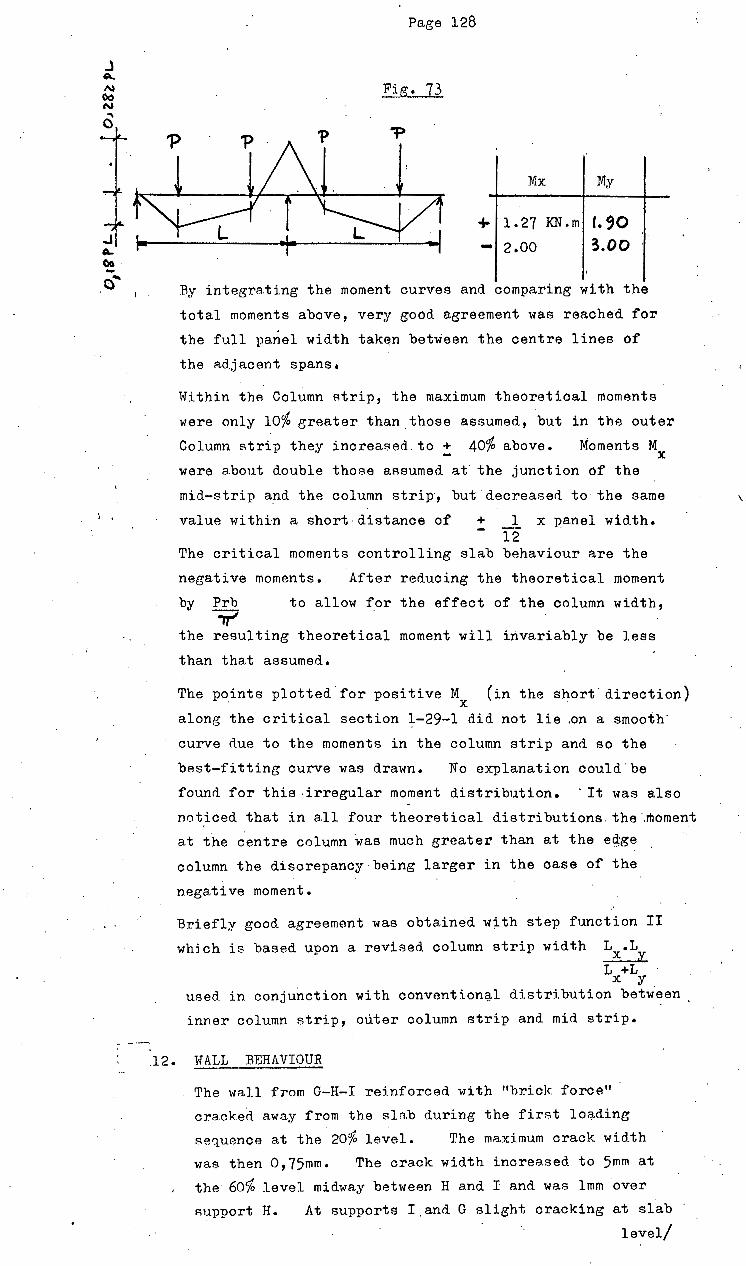
.l A. N Oo N
"' c
- -~ . .
Pa,ge 128
Fig. 73
Mx My
... 2.00 3.00
By integrating the moment curves and comparing with the
total moments above, very ,good agreement was reached for
the full pa~el width taken bet~een the centre lines of
the Rd.jacent spans.
Within thA Column strip, the maximum theoretical moments
were only 10% ,greater than_those assumed, but in the outer
Column strip they increased.to + 40% above. Moments M X
were about double those aAsumed at the junction of the
mid-strip a:nd the column strip·, but· decreased to the same
value within a short-distance of + _1. x panel wid.th. 12
The critical moments controlling slab behaviour are the
negative moments. After reducing the theoretical moment
by Prb to allow for the effect of the column width, _,..;
the resulting theoretical moment will invariably be less
than that assumed.
The points plotted for positive M (in the short· direction) X
along the ori tical section ~-29-1 did not lie .on a smooth·
·.curve due to the moments in the column strip and so the
best-fitting curve was drawn. No explanation could.be
found for this ·irregular moment distribution. · It was also
noticed that in all four theoretical distributions. the ·.moment
at the centre column was much greater than at the egge
column the discrepancy being larger in the case of the
negative moment.
Briefly good agreement was obtained w~th step function II
whj ch is based upon a revised. column strip width L .L X y L +L
X y used in conjunction with convention~l distribution betw.een
inner column strip, outer column strip and mid strip.
12. \'TALL BEHAVIOUR
The '"all from G-H-I reinforced with "brick force"
cra.ckea away from the slab during the first lo~d.ing
sequence at the 20% level. The maximum crack width
was then 0,75mm. The crack width increased to 5mm at
the 60Yo level midway between H and I and was lmm over
Ruppert H. At supports I and G slight cracking at slab
level/
\
Page 129
level indicated some relative inward movement of the top
of the 8lah rlue to its C'lnd rotations.
During the second loading sequence the maximum crack
width started at ! 2mm and increased to :t 30mm at 90% of failure
and 40mm at failure. F.xcept for the opening.of
the wall to slab .ioint, no other cracks occurred in the
wall G-H-I throughout the test.
The reinforced wall D-"E-F, open-jointed at E, behaved
in a similar fashion although the crack widths were smaller.
Hair cracks commenced at the 30% level in the first loading
and increased to 4mm at the 60% level.
The unreinforced walls A-B-C and D-E-F behaved: slightly
differently. During the first loading, hair cracks
opened in A-B-C in the first mortar joint above the
slab at the 30% level and increased to 3mm at the 60%
level. + Also at this level a smaller crack of - lmm
opened at the slab level.
\-Tall D-E-F showed a 3mm crack in the slab joint and a 2mm
crack in the joint I course above at the 6o% level.
'Hall G-A (unreinforced) showed a 0,5mm crack in the slab
joint at the 60% level.
The behaviour of the unreinforced walls in the second
loading test was similar to the first, but the walls
had wider cracks at the same ·load levels •.
Except for the horizontal cracks in the slab to wall joints
and in the first mortar joints above, no further cracks
were observed in these walls throughout either loading test.
After the formation of the above horizontal cracks, all
the walls appeared to span independently of the slab
between the supports, lead.ing to the conclusion that the
wall had negligible effect on the slab moments at the outset
and no effect on the deflections or moments after the slab
cracking load had been reached.
'13. TF:ST SHORT-COMINGS
The loadine system applied 4 concentrated loads at the
panel quarter points to simulate a distributed load.
As a result the total negative moments were 0,142 = 13% o, 125
higher and. the total posi tive;•moments were 0,18 = 29% o, 14
· higher than if the panel load was uniformly distributed.
These /
(R.26,28)
(R28)
-
'
Paee 130
These discrepancies are too large to assume equivalence.
The best methods to simulate a distributed load are to ·
place either
(a) A tank of water on top of the slab
(b) Plastic bagB filled with air between the slA.b and
a supporting frame as has been clone. by other investigators.
Dia.l gua.gep, clamped to a steel frame suspended from the same
steel girder as the hydraulic jacks, gave incorrect readings
owing to the upward deflection of the gir~er, thus
necessitating corrections. The dials could only be read
from cramped positions on top of the slab and it is inevitable
that some would be disturbed without our knowledge. Dials
should preferably be placed on stands under the slab with
sufficient head room to facilitate readings and the marking
up of cracks.
The rubber pa.ds under the slab were provided t<? permit slab
rotations and a near-uniform distribution.of ,pressure from
the supports. Unfortunately the centre pad in particular
compressed considerably ( : 4mm at so% level) although
it may have been less if the readings had been corrected
to allow for the girder's upward deflection. Steel
plates.on.roller bearings would have been ideal.
The dial guages 11sed had ranees from 5mm to 20mm. At the
so% load level and above, most of the 0 dials left the slab
and no readings were possible. It is essential that the
dials have ranges commensurate with the deflections expected.
Strain readings of the brick work were largely ineffective
as the discs ~lued to the wall either moved during readings
or fell off. However, no vertical cracks were observed
during the tests and so readings were not necessary. For
future test~, the discs should. be glued to the brickwork on
either side of vertical mortar ,joints with an epoxy at least
24 hours before the test.
~14. m<NBRAI, TBST CONCLUSIONS
Despite its shortcomings, the test enabled some useful
conclusions to be drawn as follows:~
(1) The slab behaved elastically right up to + 75% of the
theoretical Ultimate Load.
(2) The Ultimate Load in bend.ings was approximately 14%
greater than that predicted by the Yield-Line theory·
due possibly to strain-hard.ening of the steel or membrane
action or /

Page 131
action or a combination of both.
(3) For loads below the cracking load, deflection could
be pred_icted by the fini t'e difference equations U8ing
the gross section stiffness to within 25~ in all cases.
For loads below ~ of the cracking load, the deflections
could be predicted to within 10%. The deflections
throughout were less than if calculated using
the cracked section stiffness for loads less than 75~
of the theoretical ultimate, i.e. within the elastic
range of the slab. The area.A under the moment curves
agreed well with the total moments across the panel
width from elastic theory and we conclude that actual
discrete moments though not measured, would agree with
the theoretical for loads less than the cracking load.
The step-function approximation to the actual moment
distribution curve was based on a revised width of
column strip. It agreed reasonably well with the
theoretical moments but produced local overstressing
at design loads. In the actual test, no cracks were
observed at loads below 90~ of the theoretical ultimate
and hence the approximation served its purpose.
(A) Solid wa.lls of normal proportions (length:height 2,5:1)
in line with the supports had negligible effect on the
slab moments and deflections and conversely even large
slab deflections from the walls produced no cracks in
·either reinforced or unreinforced walls above the first
brick course. Similar walls in an actual slab'would
appear to require no special treatment to prevent cracks.

J •. CONCT.,TJSIONS
Tho optimum rlesign of e. flA-t concrete plate if3 that which
ensures that its strength and behaviour satisfy the following
criteria at the lowest relative ~oet.
1. (a) The UJ.timate Load capacity before failure in bending
or shea.r should be not lese than the total design load
multiplied by an appropriate Load Factor.
(b) It should behave elastically for any live load leAs
than twice the design live load but not for more thA.n
80~ of thl3 Ul tfmate Sup<'lrimpoaed Load LA. rfltatn no
permanAnt deflection after unloading.
(c) At working load, cracking,. if any, should not be visible
to the naked eye
(d) Deflections due to the transient live-load should be a
practical minimum.
(e) Creep and shrinkage deflections due to the dead load and
sustained live-loads should not exceed L or 8 mm if it
supports brick partitions and L 540
720 for all other loads.
2. The relative cost of the slab is the total cost of steel and '
concrete per square metre. If criterion l(a) only is satisfied
for minimum cost, the slab depth will be much less than if all
the criteria are satisfied, but the relative costs should not
differ by more than 10%. In terms of the building cost as a
whole this represents an increase of about 1% if the slabs are
"heavy" and less for "light" slabs.
3. The Elastic, Empirical a.nd Yield Line methods of design satisfy.
only criterion l(a) fully and this has been amply demonstrated
by many tests and structures in use. The slabs designed are
roughly equivalent in cost as well as performance. The
limitation of the span to slab depth ratio is by itself
insufficient to control deflection and cracking behaviour and
must be coupled to a limitation of concrete strains at 'mid-span.
4· The Finite Difference method enables all the criteria to be
satisfied. directly provided mid-span cracking is avoided.
However, the writer feels that more time is required by the
desie-ner for the various operations F.luch as writing and checking
the equations, calculating moments from the print-out of
deflections, plotting the graphs a.ncl detailing the reinforcement
tha.n in any other method. Furthermore, no allm-fance can be /

Pa.gA 133
' can be directly made of the effect of ·column stiffneases.
As other methods are possible which can satisfy all the criteria. '
the writar cannot justify its1use for·recta.ngular plates.
5· The Elastic-Plastic Method. using unstressed reinforcement
differs from the Elastic in the distribution of moments only, •
the cost being the same. It satisfies criteria l(a), l(b) and l(d) · ;
but ignores the others. However, they can also be satisfied
by the following·additional procedure :-
(a) Determine· the ·slab depth so that the cra.ck.ing moment
across the full panel width at mid.-span is equal to
the positive moment due to the ~ustained loads.
(b) Check the depth for punching shear by the {ormulae
recommended by Moe, Taske.r and Wyatt or the A. C. I. Code
for shear •. If necessary structural steel shear heads
oan be used to spread the.column reaction into the slab. ',
(c) Check the Elastic deflection d.ue to the sustained loads
. and hence the ultimate creep deflection which is twice
the Elastic defleotion,.by the following approximate
·.formula using the gross section stiffness.
b:.. = L (5M1 M2) where L · 48EI
/:::,. .- deflection at mid point between two columns
L = Long Span
Ml = Positive moment in the column strip
M2· = Negative If II II " "
...l .
Eo Instantaneous Elastic Modulus of the concrete
I = Gross Moment of inertia of the column strip
Alternatively the deflection can be indirectly controlled
by making L ~ 32 for all spans where L · = Longer span d
6. The writer believes that the slab deflections which may affect
brick partitions are the deflections in the plane of the wall,
of the panel centre .in relation to its ends, and not of the
panel centre point in relation to its column supports which· is
slightly greater depending on the aspect ratio. In the tests
the walls v1ere a.ble to "arch" between C?lumns independently
of the slab without distress to itself or affecting the slab
moments or behaviour.
The effect'of walls partly inter~1pted by openings in
ra.ndom positions on the slab was not investigated and could
be the /

Page 134
bA the sub,ject of further research. Light brick reinforcement
will con~iderably improve their ability to withstand uneven floor
deflection or movements without the ·sudden formation of large
cra.cks.
DistresR to brick partitions may be due mainly to the
additional load transferred from higher slabs under their creep
deflections. To reduce this possibility it is propOsed that
(a) building of walls be delayed as long as possible
(b) wall8 should not be built hard up against the underside
of the slab above but a gap of at least 10 mm should be
provtded.
(o) creep deflections of all slabs can be reduced by better
curing, longer propping through a.t least two floors and
by reducing water content of the mtxes to a minimum.
Apart from reducin~ the possibility of un~ightly oracka,
maintenance coste will be substantially :reduced.
7• The limitation of the Elastic behaviour in criterion l(b)
will permtt Plastic deformation before collapse for a li~ited
range of loading which would give warning of serious overloa.ds.
·a.· By pre-stressing the plate in both directions according to the
. Elastic-Plastic method, all criteria. are satisfied. Further
advantageB gained are as follows:
(a) Short-term'deflection is zero at sustained loads and long
term deflections are a minimum
(b) The slab is crack-free and water-tight due to the
uniform compression, brick partitions are crack-free and
overall maintenance is therefore minimised.
9. The tests carried out on the Experimental Model which was
deBigned by the Elastic-Pla.Btio method confirmed the expected
behaviour of such slabs. The. failure load war-;, ·however, 14% /
higher than predicted but this may be due to uncertainty
regar~ing the onset of yield in the steel, which may have possibly
commt:lnced later than assumed owing to the large variation in
the commencement of yteld which is possible in mild steel.
10. Optimum design can, as illustrated, be achieved in the
Drawing Offl.ce but the slab behaviour will not be optimum
unleRs thr-!re iE' full co-operation from the Contractor in
ensuring that the Engineer's carefully prep<ned specification
is carried out to the letter to ensure proper control of the
quantity of water, compaction of concrete, maintenance of
steel in the right position, curing a.nd. the propping of floors.
Provided./
Page 135
Provirled this is done, there can be no rear-;on why optimum
behaviour of flat rectaneular concrete plates cannot be
achieved economically.
11. ThA behaviour of the slab at working loads is largely
depend.r:mt upon both its tensile str~ngth and the tensile
cracking strain. Consequently _cylinrler splitting teGts
to measure and. control the concrete tenRile streneth of
flat plate:::; should. be made in a.ddi tion to crushing test!'!.
~1rther reRearch on measures or additives likely to inoreaAa
the tem:ile strf'lngth A.nd ii0oreaRe tho tenRile cracking strain
of concrete would be-a step nearer the optimum design of
even more slender flat plates.
ACKNOWLEDGEMENTS
The Writer hereby wishes to record his sincere thanks
to the Civil Engineering Faculty of the U.C.T. which placed all
the facilities of its l"aboratory a.t his disposal, to Mr. 1'1. S. Doyle,
Lecturer in St~1ctures at U.C.T. for his ~1idanoe and assistance
in preparing the experiment and to the staff of the laboratory who
so ably and enthusiastically built the test slab.

Pagf'l 136
PART 3. REFERENCES
BROTCHIE 1. General Method of Analysis of Flat Slabs and Plates
J.F. A.c.r. July 1957.
F.A. BLAKEY
,J .J. RUSSELL
2. Elastic-Plastic Ana.lysis of Transversely Loaded
Plates. Trans. A.S.C.E. October 1960. 3. A Concept for Direct Design of Structures.
Trfl.ns. I .E·I Al!Elt:r.A-1 ia. Septemhe:r 1963. 4• Flat Plate Structures Elastic-Plastic Analysis
A.C.I. August 1964. 5. A Refined Theory for R.C. Slabs. Journal I.E.
Australia. October 1963. 6. Direct Design of P~estressed Concrete Flat Plate
Structures. ( Constr.. Review. ,January 1964)
7. On Moments in Slabs (Constr. Review. March 1967)
8. Experimental Study of a Prestressed Concrete Flat
Plate Structure. (Trans. Inst. of Eng. Australia)
October 1967. 9. A Criterion for Optimal Design of Plates
(A.C.I. November 1969)
10. Deformations of Experimental Lightweight Flat
Plate Structures. (Trans. Inst. of Ehg.
Australia. March 1961)
11.· Design of Flat Plates by Simple Analysis
(Constr. Review November 1962)
12. Australian Experiments with Flat Plates.
A.C.t~. April 1963.
13. · Deflection of Flat Plate Structures.
Civil Eng. V.58 1963.
14. Deflection as a Design Criterion in Concrete Buildings
(Trans. Inst. E. Australia. September 1963) 15. Towards an Australian Structural Form - The Flat
Plate (Archi teet in Australia. Se.ptAmber 1965) 16. Changine Fashions in Concrete• Australian Bldg.
Science. December 1965. 17. An Experimf)ntal Study of Flat Jlates. C.I.B. No. 4
1965. 18. A RAviAw of Some ~xperimental Stu~ios of Slab-Column
Junction. Constr. Review July 1967.
19. Lightweight Aggregate Concrete in Flat Plate Floors
c.s.r.R.o. v.rr. - 1968. ·
20. Analytical Data for Direc't 'Design of Reinforcement
Distribution in Internal Panels of Flat Plates.
C.S.I.R.O. Australia. 1966.
21. Numerical Methods of Analysis by Computer.
Civil Eng. V .58. 1963.
22. /

Pa{Se 137
BERF.SFORD 22. TeP.ts of Ed[Se Column Connections of a FJ.at Plate
Structure. Trans. InAt. of E. Australia,. October 1967.
~ .
23. An:1lytical Bx:1mination of Propped Floors in Multi
Storey Construction. (Constr. Review. November 1964)
24• Experimental LightweiB'ht Flat Plate Structure. C.S.I.R.O.
Australia
,part I. · Measurements and Observations during Erections-1961
II.
III.
Deformat~on due to self weight - 1961
Long Term Deformations - 1961
IV. Design and Erection of Structure with Concrete Columns - 1962.
v. VI.
VII.
Deformation under Lateral Load - 1962
Design and Erection of Post Tensioned Flat
A Te~t to Dl'lstruotion - 1963.
Plate 1963 •,
VIII. Tor1t to f.g.:!J.url!l of Prl'lRtraFH'I~d f)lnbn (Oamhln 1964)
25. ShM,r :i.n Flat Plate ConRtruotj.on undl'lr TJntform Loa,d.tng
(Commonwealth 'Experimental Building Stat1.on-Tasker & Wyatt . 1963)
26. F.xperimental Investigation.of the Strength Behaviour
of Prestressed Plate. Div. . of Bldg. Research. Gamble 1964)
27. Flat Slab solved by Model Analysis- Bowen & Staffer.
A.C.I. (February 1955)
28. Strength of a Concrete Slab prestressed in TtiO Directions
(Scordelis, Pister & Lin. A.C.I. September 1956)
29. Load Test on Flat Slab floor with Steel Grillage Caps
(Meisel, Jensen, 1-Theeler. A.C.I. July 1958)
30. Ultimate Shear Strength of R.C. Flat Slabs, footings etc.
without Shear Reinforcement (1ihi tney. A. C. I. October 1957)
31. Deflection of Multiple-Panel R.C. Floor Slabs
(Vanderbilt, Sozen & Siess). Proc. A.S.C.E. -Structural
Division. August 1965.
32. Design of Prestressed Concrete Structures." T.Y. Lin
33. Yield-line Theory for Ultimate Flexural Strength of
R.C. Slabs. E. Hognestad. A.C.I. March 1953.
34. Theory of Plates & Shells. l Timoshenko, Woinowsky
& Kruger. 1953· 35· Plastic & Elastic Design of Plates and Shells.
H' oori & .Jones.
36. Rl."linforoeo. MaRoney DaEiign & Praotioe. , Proo. ·A. S.C. "F;.
DAoAmher 1961.
37. 'T'hA Intorn,otion of FloorA and. BAA,mA. Nat:i.ona.l Blc'lg.
Studiee. R~eearoh Paper No. 22. -Wood
38. European Committee for Concrete-Information Bulletin No. 35. '
39• A.C.I. Manual of Concrete Practice
40. Sudden Collapse of Unbonded Prestressed Structures
G. Rozvanny & .J. Wood. A.C. I. February 1969.

A P P E N D I X

'· ..
___ 77777/
. I
. MOVEMENT JOlMT. ·
. ' CP.ACK RUWEEN £XTEttiA.L WALL 0~ COLUMN AND IK1E.R.N~\. PAit11TION:
INTLl~\. PAl11TICN.
\
Pn.go 1~8
· WAll CHC~ DUt 10 DEFECTION Ot FLOOt t[NEATU UE WALL.
COU.\DOl.
tmKINIA CAU!tD ~y DUltCTION Cf fLAi PLAT£ ..
. .
nmECTICN
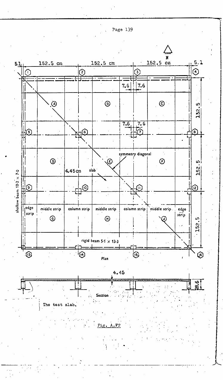
, Page 139
N S~.l~1 _____ 1_5_2~·~5_c~n_l __ --~ ___ 1_5_2 .• ~5 __ c_m ____ ~ ____ l_5 __ 2.5 c~m ____ ~_S.l
,0. I® I®
~-@ . ® . (C) I ~ """I'-, ' · I - .... ! 7.6, ' , 7-. 6--~----~'----· --+-~! ~
-~h(G) ! -~rfr11 . ~l(a) • ~. L f\" . --]. . Lt...l • ~ 'T :"
I ' ' - -·-~~ --+----4--H
· "' symmetry diagonal
® ·1- ·,®. l ! . 0
ll .-c~ 4.45cm slab' u• ,.
J(o) . -~
II
II 'I
~ II X II
Cb@J . " - "--~--~- . l1Q2:J
i _J__':~- -- ! ·~ -~®
E w--::""----+-
·~ 11 .
middle strip column strip mid.dle strip . 1
column strip ·_middle strip . : e_d~e I ..2 ~ l·edge "" · strip .
'I II I
®
:1 . . 1 ! I rigid beam 5·1 x 13·3
- h---~ - -f- ---rl""\._ I - --l- -rl"l--
·® -·'e ® Plan
4.45
· rfr · · :~· .. · J!' ~, '· Section. ,. ~,, i'.: . , •..
'I I 0
' . \ . The tes~ slab., j I
' •
;,
.) : .... : !
, . • ...
Fig. A.F2
-I
: .
. ' ''\ .nr;p I ~ . 1.{)
,-4
~ _,___· '. I
•tt .,I . 4~ .. ,, .. -~ ,1 •
~ : I ' •
... t',l •
-~- -··-- --. ·---------.----··- ---------.------- ...
. I
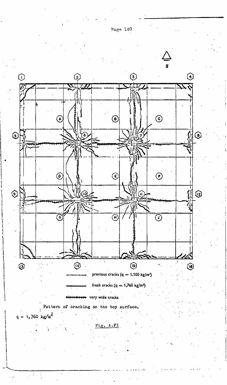
I
t I •
l l I l I
I j l
\ ·1 ~
l ·I
l
'I l 1
1
I I I
®
G)
-- previous cracks (q = 1,100 kg/m2)
.. . fresh cracks (q = 1,760 kgfm2)
I H. i HI H H very wide cracks
1 .Pattern of cracking on.the top surface.
• I
q ::: 1, 760 kg/m2
Fig •. A .F3 .
. I
11
'@
·-
0
.. '
. 'I
. ' I I !' ' I •
l:i I
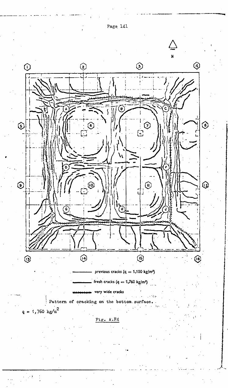
Page. 141
0
•
.® . •.
previous cracks ( -. . . q "'""" 1,100 kg/m2)
-- fres~ cracks ( _ ·
.I . oiiOIIIIO~ ver 0 q-1,760kg/m~ ....
' Pattern . y wode mcks • . - . of oraokin . . q = 1' 760 k-' 2 0 • g on the bott . 0 ••• ,., .., m . . 0 'om 0 surf' ace • .
'. .
6 -
. '
. :
.. -. -
i ~ .~ '
,...\. ' • ! I I
I . ' I
: ....
I I
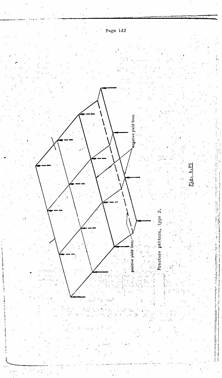
...
W ., •• -~e,_ .... -:..-
...
r ..
.,.,~
... -
,.,--
. .,.
, ..
_ ..
....
--.:
_..
.,,.
;..
•
....
....
....
. ---
,.r
.... ,--"W«~'""' _
__
_
,
•,.
l ! , _
_ . --
.--·
,..
· . . p
osi
tiv
e yi
eld
line
s .. ~·
. '
'
-~~ -..
.... '
Fra
ctu
re p
att
ern
, ty
pe
2.
·-··
---~---,.-
----
i
. ~ F
ig.
A.F
5 c
. '
. _
_:_;
_7_:
=-,_:_·=~:-··-
~=~-
-:.·
: ~=~2-~=
·:-~
~==·
~=~:
~~ .. --=~--
~-:._:
:.::_~
:_:-::
_~·:!
~:.:~-
~-:~--
---=--
~~~--~
:=---~ ·
··-----. "·
......
•
'
ne:g
ativ
e .Y
ield
lin
es
~ -·-
----
. .
'
't:l
~
OQ
(l) I-'
..p..
f\)
l I l 1 1 ·\ (i I :1 .I

,.
1.:,
'.
... QJ c:
-o .Qj ·:;:.
Q)
> ·p ';;;
&.
.•
. . . t -;
I ·.
. I
· ...... _
,. ....• "1
. ~ .. .. . ! '
. ''\ . ...
.. j
\ t . I·,
'
. ; .
. • 4 • ~ •
i
.. i
,L
•
' ': I
\
\
i \
' .. I
~ '' ' l
'
..... ·.
.· .,_
c ..... i ... ~ •
. \
.. i ·'
.. • . . . .... ·~ : ' ·. '
'... , .. :: ~ .
i ._,_
i ... ;
•.,
I ·~ • .. ~ I
. .,....
"' ~-H Q)
+> +> ~-Q)
'~ ·.+J . o· ~-
lkl
.. ~
! ~ .. i
i ... , ...
I !
'i
. ..
·'•
' .
....
'
_._

Page 144
RF.INFORCEI't1ENT DISTRIBUTION I 'IN INTERNAL PANELS
/ ,.
,. [ __
(Mo)
' . DIVISION ·OF/ MOMENTS IN A SQUARE OR RECTANGULAR PANEL
L = slo.b spo.n; rb = cffcct.ivc column ro.diua
...
Ncgntive Moment Positive 1\Ioment
Pnncl Shape Ratio Direction -~
of Column :Middle Column 1\Iiddlo Lv:Ls. rbfL11 Span . Strip Strif1 Strip Strip
. (%) (%) (%) ' (%)
1: 1 0 50 16 21' 13 0•025 48 16 22 14' 0·05 45 17 23 '15
: 0·075 42 18 25 15 - 0·1 39 18 26 17 1·1: 1 0·025 X 49 15 23 13
y 47 18 20 15 // ..
.0·05 X 45 15 25 15 y 44 19. 22 15
0·075 X 42 16 28 14 y 40 20 24 16
1•2: 1 0·025 X 50 13 2_5 12 y 46 19 .20 15
0·05 X 46 14 27 13 ·. y 42 20 22 16
. 0·075 X· 42 . ·' 14' 30 14 y 39 21 23 17 . . I
1·3: 1 0•025 X 62 11 26 11 · ..
y 44 20 20 16 0·05 X 48 12 28 12
y 41 21 21 17 0·075 X 44 13 31 12
y 38 22 22 18 1•5:1 0·025 X 64 9 29 8
- y 42 22 . 19 17 . . 0·05 X 60 9 32 9 y . 39 ·23 20 18 ,,
0·075 X 46 10 35 10 y 36 24 21 19
2il 0·025 X 66 5 35 5 y 39 26 18 17
0·05 X 60 5 39 6 y 36 27 19 18 ·-
3:1 0·025 X 66 2 39 3 y 34 31 18 17
0·05 X 47 2 46 5 y 32 31 19 18
Width of column strip = width of mid strip = t panel width
Table A.Tl

•
-·, ' I· :\ (:
i'
.... -·-------·-
\·
Page 145
:REINFORCEMENT DISTRIBUTION IN .lNTI:ItNAt.. PA~l! &.$ I I \ I • __ 1
DISTRIBUTION OF MOMENT ACROSS PA:s'EL WIDl ...
Negative Moment Positive .Mo...,t.,t Direction )ii('t · Conc:e."t,.at
Panel Shape Rat.io Column :M,~Ic. Ol/4..r- (Al ....
L 11 :Ls rb/L11 of
Strip Middle Column . ···-
Span Strip Strip :·Stn~ ~ (o.v.) Pn (%) (%) (%) (%)
1: 1 0 76 24 62 38 0·025 ,• 75 . 25 62 as 1·63 0·05 72 28 62 38 1•35 0·075 70 30 61 39 1•20 0·1 68 32 61 39 ·1·12
I+: 1 0•025 X 78 . 22 63 37 1·73 y 73 27 58 42 1·58 .
0·05 X 75 25 63 37 1•40 y. . 70 30 58· 42 1·30
0·075 X 72 28 64 36 1·23 y 68 32 59 41 .: 1•15
1•2: 1 0·025 X 80 20 68 32 1·77 y 71 29 57 43 1·53
0·05 X. 77 23 67, 33 1•41 . y 68 32 57 43 1·26 0·075 X 75 25 67 33 1•22
y 65 . 35 57 43 1•13 1 .. 3 :1 0•025 X
. . 82 71 29 1·83 18
y 69 32 55 45 1·45 . .. 0·05 X 80 20 71 29 1·46
y 66 34 55 45 1·22 0•075 X 77 23 71 . 29 1·28
y 63 37/ 55 45 1·11 1·~: 1 0·025 X 86 14 77 23 1·90
y 65 35 53 47 1·36 0·05 X 84 16 77 23 1·48
y 62 38 53 47 1·15 0·075 •· X 81 19 77 23 1•29
' y 60 40 53 47 1·06 211 0·025 X 92. 8 87 )3 2·13
1': 60 40 51 49 1·21 0·05 X 91 9 86 14 1·63
y 57 43 51 49 1·06 3:1 0·025 X· 97 3 93 .. 7 2·49
y 55 45 50 ·so 1·08 0·05 X 96
., 4. 90 10 1·78
y 53 47 50 50 1·02 ;
Code requirement (see Table I) 76 24 60 40 1·0t
• Rntio of stool percentage per unit width over column to nvernge p<'rcent.nge of top stool in colmnn strip.
I
t 25% of negative stool within the column strip must. be locnt<'d within t.ho width 2rd+2t.. ~ ~ \J,al"-· of Coft~,..n Strit··::. .,.d«-. o( M:t~. S'tr;p • 12 of 'P~t'\et \J,tt~.
Table A.T2
\

~ ~·
~
~--
" . \
·I
lx I
. ·
lA
JB
_<
:>-
e-1
I
fi~-~-L-,--
-:l
-.-
l . I
Ll
i-0
-t=
l--1
'
.-
Mom
ents
Mx
alon
g co
lum
n ce
ntre
lin
e
'~-·
-·-·
. -··
. --
----
----
-------------~ -
----
----
----
~
,......_
__
-.·--·--~--. -.-
...
\ ·.
M
_,,_
. ib
t"
.
Col
umn
cent
re
.·Gne
o-~
I I
,.....
_
~
:;:
0·1
_:. :~-·~ --~-~.:~
1 _
_ ___
___ --~
om
ent
lll'>
•n
u 1
0n
s m
a
.. _..
un
ifo
rmly
lo
aded
sq
uar
e in
tern
al
pan
el f
or v
ario
us
rati
os
of
colu
mn
.
rad
ius
rb t
o s
lab
sp
an i
.
Cri.
tical
neg
ativ
e· m
omen
ts
My
norm
al t
o co
lum
n ce
ntre
. lin
e
Cri
tical
pos
itiv
e m
omen
ts
My
norm
al t
o pa
nel
cent
re l
ine
---·-~---~---
......
.,.
-·
1
~
·t:;
i .... z ""1
0 ~
a t,:j a= t;:.1 z ~ ~
rn
·~
~ .... ~ .... ~ .... z ~ t;:.
1 ~ t"
1-j
> z t;
1 t<
a!
'---:.
.
~
,,-,
"d
Ill
Gq (I)
1-'
.p
:. 0
'\

' .
B
I~
Moments Mx along column · centre line
Column centre line
0·1
0·1
0 n
Pa.ge 147
Critical negative moments My normal to column centr~ line
Critical negative. moments My · normal to panel centre line
B ...;c ll)
6
Fig. a-Moment distributions over width L., for rectangular panel (LJi = 1·5 L.,) under uniform loading (of. Fig. 16).
The appropriate step functions under this theoretical treatment were obtained from numerical integration of the curves. These numerical integrations were c~rried out on a National Elliott 803 computer for both the positive and negative momenf curve&.
Fig. A.F8
,\
I •
i.
I._
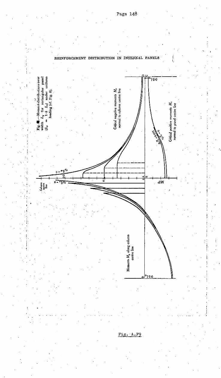
~ ~
.... --~----
~:
~------
.,._ , _
__
_ .'
-~
_, ~-
+:
Mom
ents
M9
alon
g co
lum
n ce
ntre
lin
e
•. ~-·~-'
. Col
umn
cent
re
line
OIA
B
~ ::!-:~
/
-....:
Fig
••. -
Mo
men
t dis
trib
uti
on
s o
ver
w
idth
L
11
·for
re
ctan
gu
lar
pan
el
(L11
=
1
· 5
L.,)
u
nd
er
un
ifo
rm
load
ing
(cf
. F
ig.
8).
Cri~
cal
nega
tive
mom
ents
M
x no
rmal
to
colu
mn
cent
re ~ne
--=
==
==
==
lo
Cri
tical
pos
itive
mom
ents
M
,, no
rmal
to
p'ID
e.l
cent
re ~ne
~I I I
----
~~-
~
t:=.l' .... z I:J
0 ~
0 t:! :s: t::.
l z ~ t:l .... Ul ~
~ .... t:;
l c:l ~ .... 0 z .... z
-"tS
Ill
.... z
~
(!)
~
t:=.l ~
t-' ~
>
co
t-4
I'd > z ~ t-4
Cll
.---~

Moments Mx along column I cen Ire line
B ><
-J ll'l 6
Column centre line
0 II
-.l"' --;::>
0·1
OA
"' D ~ 6
Pag e 149
Critical negative moments My normal to column
centre line
B ..:;c lfl . 6
rb/L = 0
0·1 Critical positive moments Mu normal to panel centre line
Fig. W.-Moment distributions over width L., for rectangular panel (L11 = 2 L.,) under uniform loading (of. Fig. 18).
- · --- ·· -- - ----- --- - - - ···· ---- ··- ·-· - ····· ·--·-__.. ____ ... _ ___ _____________ .._ ..... ~. · · - - - --~- ---
Fig . A.FlO
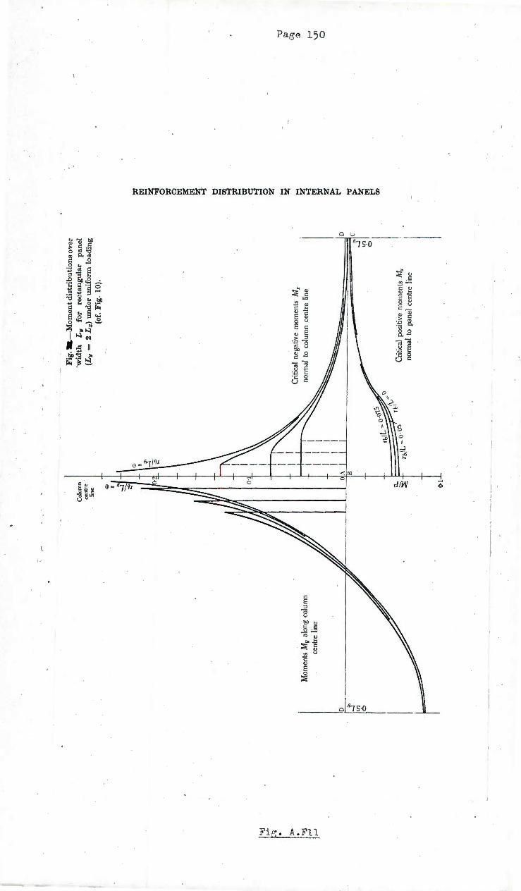
~
1-'· > . ~ t-'
t-'
.D "'
-.l
lfl 6
Mom
ents
My
alon
g co
lum
n ce
ntre
lin
e
Col
umn
cen
tre
line 0 R
OIA
IB
"' -.
l ~
1[)
1 ...
..
0...
' ~
rb/L
~ o-o
:> tb
l
0·1
Fig
. a-M
om
en
t dis
trib
uti
on
s o
ver
·w
idth
L
v
for
rect
ang
ula
r p
anel
(L
v =
2 L
:z:)
un
der
un
ifo
rm l
oad
ing
(c
f. F
ig.
10).
Cri
tica
l ne
gati
ve
mom
ents
M
x no
rmal
to
colu
mn
cent
re l
ine
D
~'l
0
Cri
tica
l po
sitiv
e m
omen
ts M
x no
rmal
to
pane
l ce
ntre
lin
e
~
J.xj ..... ~ 0 ~
0 J.xj ~
J.xj ~
-tj .....
112 ..., ~
.....
b:t s .....
0 z ..... z ..... ~ J.xj ~ ~ t'
I-tt ~ J.xj
t'
112
'U
ill
~
(j)
1--'
\Jl
0
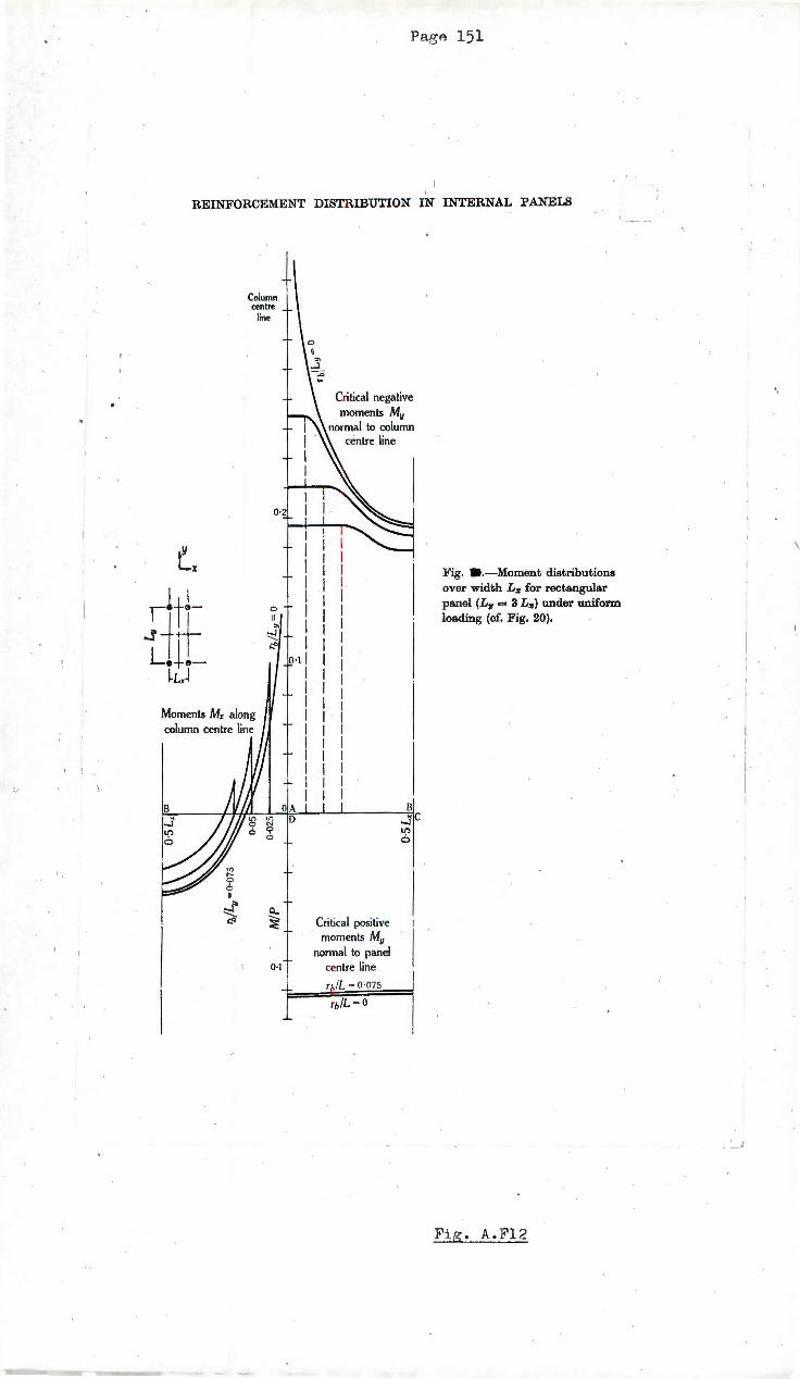
l•
PagA 151
REINFORCEMENT DISTRIBUTION IN INTERNAL PANELS
Column centre ,.
11ne
0·2
Lx ,ltl- 0
II -+t "' -...1 ;:.>
Le~e-~L.J
Moments Mx along column centre line
0..
0·1
Critical negative moments My
normal to column . centre line
B ..sc ll')
6
~ Critical positive . moments My normal to panel
0·1 centre line
r&!L = 0 ·075
Fig. a .-Moment distributions over width Lz for rectangular panel (L11 = 3 Lz) under uniform loading (cf. Fig. 20).
Fig . A.F12
\_

>xj
!-'·
;I>
0 >x
j .....
.. V
J
D .s l/')
6
Mom~n
ts M
y al
ong
colu
mn
cent
re l
ine
0 ~r-
-..J
cen
tre
-:.:a
lin
e
I 0 ft "' ~
. 1e
()-2
0·1
OIA
B
Q..L
--
~
0·1
Fig
. --M
om
en
t dis
trib
uti
on
s o
ver
w
idth
L
11
for
rect
ang
ula
r p
anel
(L
11
= 3
L,.)
un
der
un
ifo
rm l
oad
ing
(c
f. F
ig.
12).
Cri
tica
l ne
gati
ve m
omen
ts M
x no
rmal
to
colu
mn
cen
tre
line
D
~l
Cri
tical
pos
itiv
e m
omen
ts
Mx
norm
al t
o pa
nel
cen
tre
line
~
tzj s 0 ~
a tzj
~
tzj ~ t;j .....
00
t-3
~
.....
b:l ~ .....
0 z z ..... ~ tz
j ~ ~ t"'
'"d > z tz
j t"
' 0
0
'""d
(lJ
(q (I)
:-'
\J1
(\)

Page 153
~ ·-~
~ 4--" I
-r J! J 4c w "' "' ~ q
f v d s w ~ t ... 1..
0 0
t U"'
w J \1 -Cl
('I ,.n ~ ' ~ . 0 <{ ~
. \:; <! 0
-4- u:

,
Pa ,e 154
Fi • A.P4
lab aft r ailu e, s t· l . upportin ,
wall. anrl loa in.~ ri •
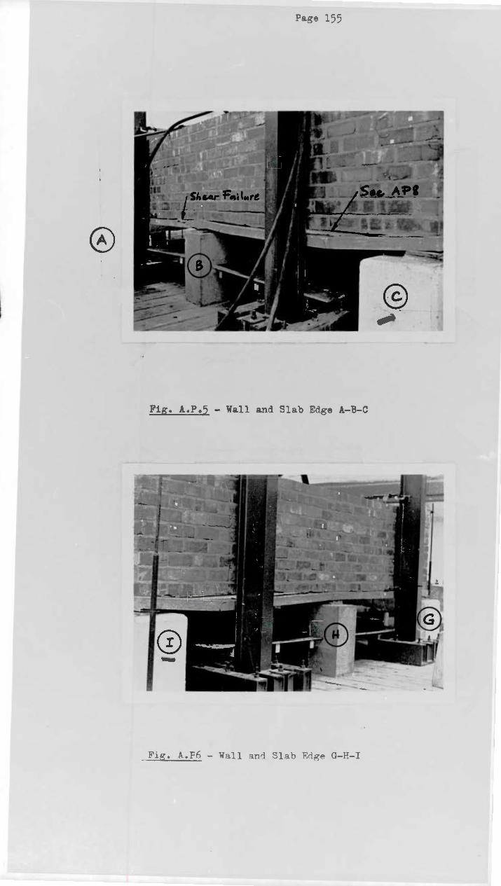
Pa~e 155
I Fig . A.P. 5 - Wall and Slab Edge A-B-C
Fi~. A.Pn - W~l1 ~n~ ~lab F.rl~~ G-H-I

F" • A.P1 - j acks in top of lab and ghear
failu ove B
®-
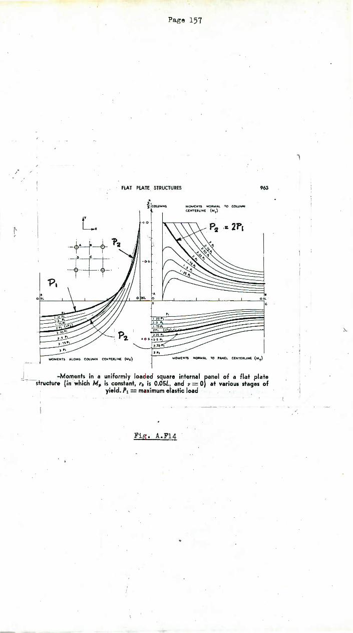
f' 1
-
• Q.>L
Pag e 157
FLAT PLATE STRUCTURES
L. ·+-i-+ l++ . . .
ALONG COl.UMH C[NTE.RLIN( ( ... )()
.. 2 i COWMNS
+ 0
UOM£NTS NORMAl ·'TO CO\.U .. N
C.(NTlALIN( (My)
.: 2J>,
963
.• -Moments in a uniformly loaded square internal panel of a flat plate ---structure (in which M, is constant, rb is O.OSL, and v = 0) at various stages of
· yield. P1 = maximum el'astic load
Fig . A.Fl4