Embed Size (px)
Citation preview

1
TOWN OF HAMILTON SKAGIT COUNTY, WA
TOWN OF HAMILTON WATER SYSTEM PLAN
SYSTEM ID# 30700 0
Prepared For: Joan Cromley, Mayor
Prepared By:
Carl Garrison, PE Garrison Engineering
May 6, 2013
Revised: May 29, 2013
(includes signed consistency form)
Notes, Disclaimers:
Garrison Engineering takes no responsibility for items not specifically addressed within this report. Some of the documents in this report were prepared by others. Garrison Engineering makes no claims
as to the accuracy or completeness of such work. These items have been included as a courtesy to the owner and review agency in an effort to present a complete water system plan.
This water system plan is valid only for the specific project shown above and herein. Further, this report is valid only if it is bound as it originally left this office, and contains all of the sheets as originally bound. Any sheets, which are not bound to the original complete set, are not valid and shall not be used (excluding authorized, stamped addenda).
This report includes 59 pages and 23 Appendices

2
3
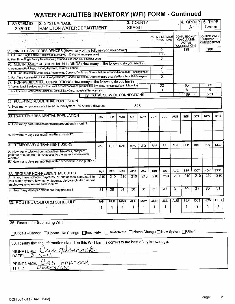
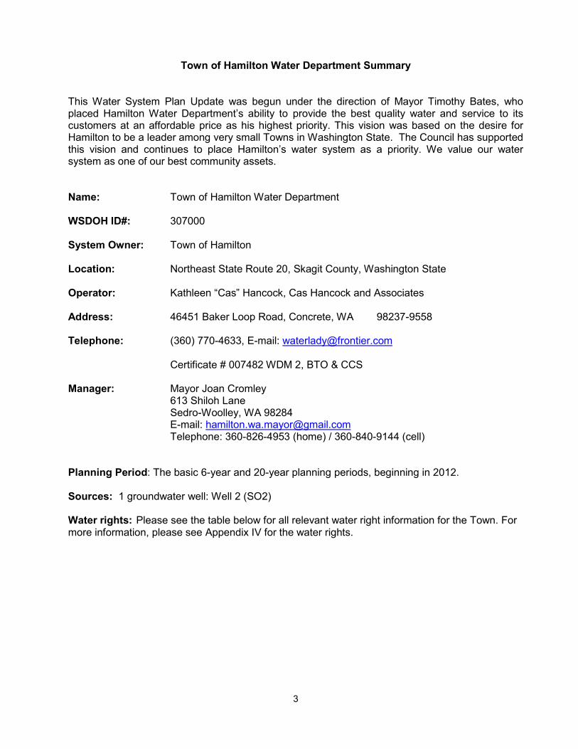
Town of Hamilton Water Department Summary This Water System Plan Update was begun under the direction of Mayor Timothy Bates, who placed Hamilton Water Department’s ability to provide the best quality water and service to its customers at an affordable price as his highest priority. This vision was based on the desire for Hamilton to be a leader among very small Towns in Washington State. The Council has supported this vision and continues to place Hamilton’s water system as a priority. We value our water system as one of our best community assets. Name: Town of Hamilton Water Department WSDOH ID#: 307000 System Owner: Town of Hamilton Location: Northeast State Route 20, Skagit County, Washington State Operator: Kathleen “Cas” Hancock, Cas Hancock and Associates Address: 46451 Baker Loop Road, Concrete, WA 98237-9558 Telephone: (360) 770-4633, E-mail: [email protected] Certificate # 007482 WDM 2, BTO & CCS Manager: Mayor Joan Cromley
613 Shiloh Lane Sedro-Woolley, WA 98284 E-mail: [email protected] Telephone: 360-826-4953 (home) / 360-840-9144 (cell)
Planning Period: The basic 6-year and 20-year planning periods, beginning in 2012. Sources: 1 groundwater well: Well 2 (SO2) Water rights: Please see the table below for all relevant water right information for the Town. For more information, please see Appendix IV for the water rights.

4
Water Right Number Priority Date
Instantaneous Pumping Rate
(Qi) (gpm)
Annual Pumping Rate (Qa) (acre-feet
per year)
Purpose of Use
G1-20003C 3-02-1972 36 35 Municipal/Domestic
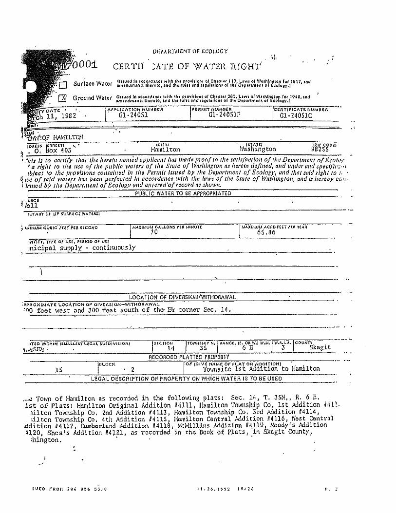
G1-24051C 3-11-1982 70 65.86 Municipal/Domestic
G1-28066A 9-30-1999 30 36
For mitigation only. As needed for stream augmentation purposes (non-consumptive use) in accordance with the Town of Hamilton water right mitigation plan for Little Carey’s Creek (see Appendix VI)
Total: 106(+30) 100.86(+36) Water System Demands: ADD Design 290 gpd/ERU* MDD Design 475 gpd/ERU* Year 2012 2018 2032 ERU Growth/Increase projections 149 170** 184**
Peak Hour Demands Design (PHD) 100 gpm 155 gpm* 164 gpm* * These numbers should be updated for the next Water System Plan cycle or when the Town needs more approved connections with at least 2 full years of meter readings using the presently upgraded water system. See chapter 4 for more details. **As development begins to occur north of State Route 20, the calculations for ERU’s, Storage, and Water System demands will be updated as necessary to adequately represent the number of new connections added to the Town. Fire Flow (FF) for Single Family & Duplex Residential within the Urban Growth Area is 1000-gpm for 60 minutes duration and the fire flow for the Janicki Plant is 2,850-gpm for 120 minutes. FF Storage for Residential 60,000 gallons FF Storage for Commercial 342,000 gallons System Storage: Two 290,000 gallon concrete water reservoirs, 30’ Ø x 55’ tall. Total storage for drinking water: 580,000 gallons. One 23,500 gallon concrete storage tank for Little Carey’s Creek stream mitigation. Equalizing Storage: Equalizing Storage (ES) for 2012 = 0 gallons, ES for 2018 =7,800 gallons, ES for 2032 = 9,300 gallons

5
Fire Suppression Storage: Fss = 342,000 gallons Standby Storage: Standby Storage (SS) for 2012 = 495,637 gallons, SS for 2018 = 488,287, SS for 2032 = 486,937 gallons.
System Pumping: A 10hp submersible pump capable of delivering 136 gpm has been installed in well S02. All connections are served by gravity. (106 gpm for Municipal/Domestic use and 30 gpm for mitigation only)
Total Customers: In 2012, there were 124 metered water connections, including 109 residential connections, 3 small RV parks (serving 22 RVs through 6 meters), 6 very small, 2 small and 1 large commercial customers.
Design Year: 2012: 124 connections (serving 149 ERUs); 2018: 130 connections (serving 170 ERUs); 2032: 144 connections (serving 184 ERUs); WSDOH Approved Connections 193 (Residential), 251 (Total). Future System Demands: Based on historical usage, the system is expected to increase by 1 new residential connection per year over the next 20 years. Janicki plant is expected to reach full development within the next 6 years (to 30 ERUs) Existing Water Treatment: Chlorination with sodium hypochlorite followed by manganese greensand filtration (106 gpm capacity) is provided. A sufficient dosage of chlorine is added ahead of the treatment system to oxidize the iron and manganese, carrying a residual through the reservoir and an additional injection of chlorine immediately after storage to carry the residual to the extreme ends of the distribution system. Sediments in the backwash water from the filters are allowed to settle out, and the water is recycled to the treatment system. Disinfection is still operated today but the filtration was discontinued in October 2010.
Proposed Improvements: The following summary of recommended improvements is based on the conclusions of this report. The outline describes the recommendations for the 6 and 20 year planning periods. These are discussed in more detail in Chapter 6.
System Improvements 6 year-planning period:
Monitoring well: Reconnection of electronics and monthly monitoring of the SWL and weir levels.
Replace Automatic Dialing System Controller Purchase of 10hp replacement well pump to have on hand for back-up Leakage Control Program Well Head Protection Program Water Conservation & Water Use Efficiency Programs Replacement of aging AC distribution system main along Cumberland Avenue (north of
Hamilton street)
20 year-planning period: Development of a second source of supply Water main looping Replacement of aging distribution system main along Nolle Avenue (between Michigan Ave
& Water Street) / Install new 8” pipe along Water Street between Nolle & Railroad Ave to create a loop

6
Town of Hamilton Water Department Water System Plan
Table of Contents
Town of Hamilton Water Department Summary .............................................................................. 3 Chapter One: Introduction ........................................................................................................... 11 1.1 Authorization/Objectives ........................................................................................................ 11 1.2 Scope of Work ........................................................................................................................ 11 1.3 Water System Description ....................................................................................................... 11 1.4 Population and Water Demand Projections ............................................................................. 12 1.5 Source Capacity ...................................................................................................................... 12 1.6 Water Transmission, Pumping, and Storage ........................................................................... 13 1.7 Water Quality and Treatment .................................................................................................. 13 1.8 Conclusions ............................................................................................................................ 13 1.9 Ownership & Management ...................................................................................................... 14 Chapter 2: Service Area Description ........................................................................................... 16 2.1 Introduction ............................................................................................................................. 16 2.2 Location and Surroundings ..................................................................................................... 16 2.3 Town Service Area Zoning and Skagit County Land Use ........................................................ 17 2.4 History ..................................................................................................................................... 17 2.5 Population ............................................................................................................................... 18 2.6 Topography and Geography ................................................................................................... 19 2.7 Climate .................................................................................................................................... 19 2.8 Proposed Development Projects ............................................................................................ 19 2.9 Water Service Area Agreements ............................................................................................. 20 2.10 Retail Service Area Policies .................................................................................................. 20 Chapter 3: Existing System .......................................................................................................... 23 3.1 Introduction ............................................................................................................................. 23 3.2 Source .................................................................................................................................... 23 3.2.1 Well S02............................................................................................................................... 23 3.2.2 Monitoring Well .................................................................................................................... 24 3.3 Water Quality .......................................................................................................................... 24 3.3.1 Radionuclides ...................................................................................................................... 24 3.3.2 Volatile Organic Chemicals .................................................................................................. 25 3.3.3 EDB & other fumigants ......................................................................................................... 25 3.3.4 General SOC’s ..................................................................................................................... 25 3.3.5 Herbicides, Insecticides, & general pesticides. ..................................................................... 25 3.3.6 Asbestos .............................................................................................................................. 25 3.3.7 Inorganic Compounds .......................................................................................................... 25 3.3.8 Nitrates ................................................................................................................................ 25 3.3.9 Lead and Copper ................................................................................................................. 25 3.3.10 Bacteriological .................................................................................................................... 25 3.3.11 Total Trihalomethanes and Halo Acetic Acid 5s ................................................................. 26 3.4 Source Treatment ................................................................................................................... 26 3.4.1 Disinfection .......................................................................................................................... 26 3.4.2 Iron and Manganese Treatment ........................................................................................... 26 3.5 Distribution and Pressure Zones ............................................................................................. 27 3.5.1 Proposed Pipelines .............................................................................................................. 27 3.5.2 Pressure Zones .................................................................................................................... 28 3.6 Storage ................................................................................................................................... 28

7
3.7 Control/Telemetry .................................................................................................................... 29 3.8 Operation & Maintenance Schedule ........................................................................................ 29 Chapter 4: System Analysis ......................................................................................................... 30 4.1 Introduction ............................................................................................................................. 30 4.2 Water Usage ........................................................................................................................... 30 4.3 Historical and Existing Demands ............................................................................................. 30 4.4 Water System Future Demands .............................................................................................. 32 4.5 Supply ..................................................................................................................................... 34 4.6 Water Quality Issues ............................................................................................................... 35 4.6.1 Wellhead Protection ............................................................................................................. 35 4.6.2 Safe Drinking Water Act ....................................................................................................... 35 4.6.3 Manganese .......................................................................................................................... 35 4.7 Power Supply .......................................................................................................................... 36 4.8 Control .................................................................................................................................... 36 4.9 Distribution System Requirements .......................................................................................... 36 4.10 Hydraulic Evaluation ............................................................................................................. 37 4.10.1 Scenarios ........................................................................................................................... 37 4.10.2 Model Results & Analysis ................................................................................................... 37 4.11 Water Loss ............................................................................................................................ 38 4.12 Storage ................................................................................................................................. 39 4.12.1 Total Storage Capacity ....................................................................................................... 39 4.12.2 Dead Storage ..................................................................................................................... 39 4.12.3 Operational Storage ........................................................................................................... 39 4.12.4 Equalizing Storage ............................................................................................................. 39 4.12.5 Fire Suppression Storage ................................................................................................... 40 4.12.6 Standby Storage ................................................................................................................ 40 4.13 Review of Source, Storage and ERU Capability .................................................................... 41 Chapter 5 Water Conservation Plan, Water Use Efficiency Program & Water Rights Analysis ...... 42 5.1 Introduction ............................................................................................................................. 42 5.2 Background ............................................................................................................................. 42 5.2.1 State Conservation Planning Requirements ......................................................................... 42 5.3 Water Conservation Program .................................................................................................. 42 5.3.1 Conservation Program Goals and Objectives ....................................................................... 42 5.3.2 Evaluation and Selection of Alternative Conservation Measures .......................................... 43 5.3.3 Technical Assistance ........................................................................................................... 43 5.3.4 System Measures ................................................................................................................ 44 5.3.5 Incentives and Other Measures ............................................................................................ 45 5.3.6 Conservation Program Monitoring ........................................................................................ 46 5.4 Water Use Efficiency Program ................................................................................................ 46 5.5 Water Rights Analysis ............................................................................................................. 47 Chapter 6 Proposed System Improvement Program ..................................................................... 48 6.1 Introduction ............................................................................................................................. 48 6.2 Improvement Criteria ............................................................................................................... 48 6.3 Project Proposals .................................................................................................................... 48 6.4 Immediate ............................................................................................................................... 48 6.5 Six Year Capital Improvements ............................................................................................... 49 6.6 Twenty Year and beyond Capital Improvements ..................................................................... 50 6.6 Improvement Schedule ........................................................................................................... 52 Chapter 7 Financial Program ........................................................................................................ 53 7.1 Introduction ............................................................................................................................ 53 7.2 Monthly Service Charges ....................................................................................................... 53

8
7.3 Capital Improvement Charges ............................................................................................... 53 7.4 Financial Status ..................................................................................................................... 54 Chapter 8 Construction Standards ................................................................................................ 55 8.1 Introduction ............................................................................................................................. 55 8.2 Service Applications ................................................................................................................ 55 8.3 Construction and Design Standards ........................................................................................ 55 8.3.1 Scheduled improvements ..................................................................................................... 55 8.3.2 Unscheduled Improvements ................................................................................................. 56 8.4. Performance Standards ......................................................................................................... 56 8.5. Construction Procedures ........................................................................................................ 56 8.6. System Design Standards ...................................................................................................... 57 Chapter 9 Source Protection ......................................................................................................... 59 9.1 Introduction ............................................................................................................................ 59 9.2 Ground Water Contamination Initial Assessment ................................................................... 59 9.3 Wellhead Protection Program ................................................................................................ 59 9.4 Resource Protection ................................................................................................................ 59

9
List of Appendices
Appendices Appendix I Water Facilities Inventory (WFI) form Appendix II Town of Hamilton Water Service Ordinance #297 Appendix III Easements Appendix IV Water Rights and Water Right Self-Assessments Appendix V Consistency Forms Appendix VI Little Carey’s Creek Water Right Mitigation Plan Appendix VII Typical Stream Mitigation Daily Log Appendix VIII Service Area Maps Appendix IX Past and Present Water Use Figures Appendix X Water Quality Monitoring Program Appendix XI Treatment Discontinuity Appendix XII Emergency Response Plan Appendix XIII Hydraulic Analysis Appendix XIV Wellhead Protection Program Appendix XV Water Quality Documents Appendix XVI DOH Ground Water Treatment Plan Reports Appendix XVII Well Log Appendix XVIII Well Pump Curve Appendix XIX Water Use Efficiency Program documents Appendix XX Water Conservation Plan documents Appendix XXI Franchise agreement Appendix XXII Budgets Appendix XXIII Maintenance & Operation Schedule

10
Glossary of Terms
Definition Acronym Town of Hamilton Water Department Town Water System Plan WSP Water Service Area WSA Washington State Department of Health WSDOH Equivalent Residential Unit ERU Washington State Department of Ecology WSDOE Capital Improvement Plan CIP Developers Extension Agreement DEA Critical Water Supply Service Area CWSSA Safe Drinking Water Act SDWA Inorganic Compounds IOC Synthetic Organic Compounds SOC Volatile Organic Compounds VOC Radionuclides RAD Disinfection By-Products DBP Total Trihalomethanes TTHMs Halo Acetic Acid 5 HAA5s Environmental Protection Agency EPA Average Day Demand ADD Maximum Day Demand MDD Peak Hourly Demand PHD Gallons Per Day GPD Gallons Per Hour GPH Gallons Per Minute GPM Pressure Reducing Valve PRV Town System Leakage DSL Operating Storage OS Equalizing Storage ES Standby Storage SB Dead Storage DS Fire Suppression Storage FSS High Density Polyethylene HDPE Backflow Assembly Tester BAT Cross Connection Specialist CCS Double Check Valve Assembly DCVA Reduced Pressure Backflow Assembly RPBA Fire Flow FF Water Treatment Plant WTP Lineal Foot lf Hydraulic Grade Line HGL Polyvinyl Chloride PVC Annual Flow Amount Qa Time of Travel TOT Average Mean Sea Level AMSL Federal Emergency Management Act FEMA Safe Drinking Water Act SDWA

11
Chapter One: Introduction
1.1 Authorization/Objectives The Town of Hamilton Water Department (Town) operates as a Municipal Group A water system under the laws of the State of Washington. The Town Mayor and Council authorized this updated Water System Plan in 2012. The objectives of this plan are to address the existing conditions of the Town system, determine future demands, and to develop a schedule and financial plan to upgrade the system. This information will provide the Town with the information needed to continue to meet the water needs of its customers and also meet the Washington State Department of Health (WSDOH) requirements. This plan will also replace the previous Water Plan prepared in 2002 and updated in 2007. It is recommended that this plan is updated on an annual basis to ensure accuracy and utility.
1.2 Scope of Work This 2012 Water System Plan (WSP) Update has been prepared according to requirements outlined in the 2009 Washington State Department of Health (DOH) Water System Design Manual to fulfill the water system's regulatory obligations under Washington Administrative Code (WAC) 246-290-100. Principle objectives of the WSP include the following: Review service area boundaries and policies Review minimum performance and design standards and policies Identify water service requirements based on projected land use and development Assess existing system capabilities Assess existing system deficiencies Develop a capital improvement program to provide for existing and future needs
Current system conditions are reviewed and presented, along with evaluations of the 6-year (2018) and 20-year (2032) planning horizons.
1.3 Water System Description The Town is primarily a residential community with a limited business area. The majority of the water retail service area is located south of State Route 20, within a relatively flat floodplain just north of the Skagit River. Within the retail service area, land slopes gently to the south and west toward the river. Elevations are generally between 90 and 125 feet above mean sea level (AMSL). In 2012, approximately 548 customers were served through 124 connections (including the commercial enterprises of Janicki Inc.). The water supply is provided through a single well located outside of the floodplain at an elevation of approximately 250 feet. High levels of Manganese used to be filtered at the treatment facility located next the well. The system operates on gravity flow from the two main 290,000 gallon reservoirs located at the well site; Pressure Zone #1. The lower part (south of State Route 20, Pressure zone #2) is protected from too high pressure by a main Pressure Reducing Valve (PRV) Station located just north of State Route 20. This PRV station will need to be relocated south of State Route 20 so that the full head in the reservoirs would be available for fire flow for the Janicki plant. See chapter 4 & 6 for more details.

12
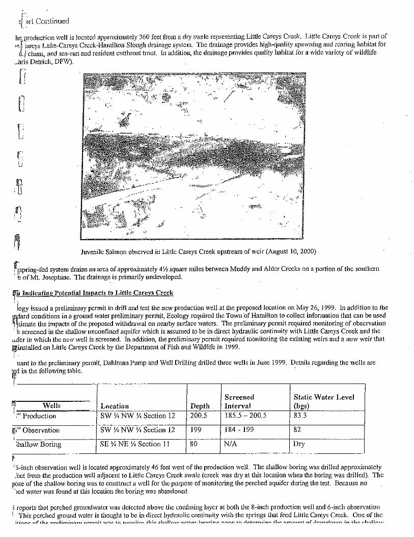
There is also an additional 23,500 gallon mitigation reservoir at the well site to supply Little Carey’s Creek, a year-round fisheries habitat that flows near the well site, with water during the summer months (see chapter 2 for more details on the fisheries mitigation program)
See Map 9 - Water System Map in Appendix VIII for main sizes and infrastructure locations.
Table 1.3 -- Pressure Zones Zone 1 295’ HGL Shiloh Lane Gravity Service from Reservoirs.
Zone 2 250’ HGL Reduced Zone
(includes Janicki Property) (1)
Pressure Reduced Service from Zone 1 Reservoirs
(1) The Janicki property will switch from zone 2 to zone 1 once the PRV station is relocated from north to south of Highway 20 at a point after the Janicki 16” pipeline connection, so that there is no PRV flow restriction serving the hydrants and Janicki plant.
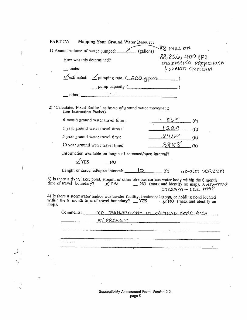
1.4 Population and Water Demand Projections In 1978, the Town reached a maximum of 174 service connections. In 2001, there were only 107 connections. Currently, the Town serves approximately 548 people with 124 connections (including 200 Janicki employees), with an average demand of 33,264 gallons per day and an estimated peak day demand of 46,816 gallons per day. The Town estimates slow growth in the retail service area with an increase of one residential connection per year for the next 20 years. The total annual water consumption was approximately 12,217,624 gallons (from 9/1/2011 to 8/31/2012), and is expected to increase to 20,005,650 gallons by the year 2032. The average day demand per ERU used in this report has been established by water records at 290 gallons and the maximum day demand per ERU at 475 gallons per day, based on 3 years of historical data. Please see chapter 4 for more details. In addition to the normal growth projected by the County, there are two developments that may increase water usage above this general trend. Further discussion on development is discussed in Chapter 2.
1.5 Source Capacity Water rights have been issued for a total of 136 gpm (New G1-20003C; Transferred G1-24051C); including 106 gpm for municipal purposes and 30 gpm (new G1-28066A) for fish mitigation (Water Rights are included as Appendix IV). A 10hp submersible pump capable of delivering 136 gpm has been installed. An automated control system restricts flow to the Town’s distribution system to 106 gpm; the balance of the flow is diverted to a mitigation tank adjacent to the Town’s storage reservoirs. At this capacity and with existing reservoirs, the Town has the capacity to serve 279 ERUs or residential connections. The target number of connections for 2032 is considerably less than this, at 184 ERU’s. See chapter 4.4 for more details.

13
1.6 Water Transmission, Pumping, and Storage The capital improvements discussed in this report are oriented around water quality and public health improvements, additional looping of the system, and replacement of older mains and valves.
1.7 Water Quality and Treatment The Town’s water is supplied by one groundwater well. The quality of the system’s water supply has been good and has met or exceeded all current DOH drinking water standards for primary contaminants. The Well source has high levels of manganese that were initially filtered to meet state DOH recommended levels for secondary contaminants. In 2009, the Mayor asked the DOH staff to assist with exploring options to reduce the exorbitant cost to the Town for operation and treatment. The DOH Engineer for Skagit County and the Town made an agreement to monitor manganese levels in both the raw (untreated) water and the finished (treated) water for 1 year. Based on the data collected and customer input, on October 13, 2010 the Town Council voted to discontinue operation of the manganese greensand filtration equipment, thereby saving the Town approximately $30,000 per year in Operator/operations costs. See Appendix XI for more details. The Town is currently collecting raw water samples for bacterial analysis (in addition to the required distribution system samples) in anticipation of discontinuing disinfecting the drinking water. This option would further reduce treatment and operations costs. See Appendix XI for the first four laboratory results (October 2012 – January 2013). The drinking water regulations are constantly changing and will require additional monitoring and reporting in the future in an effort to ensure safe drinking water for its customers. Therefore, it is imperative that the Town stay abreast of the regulations to maintain compliance.
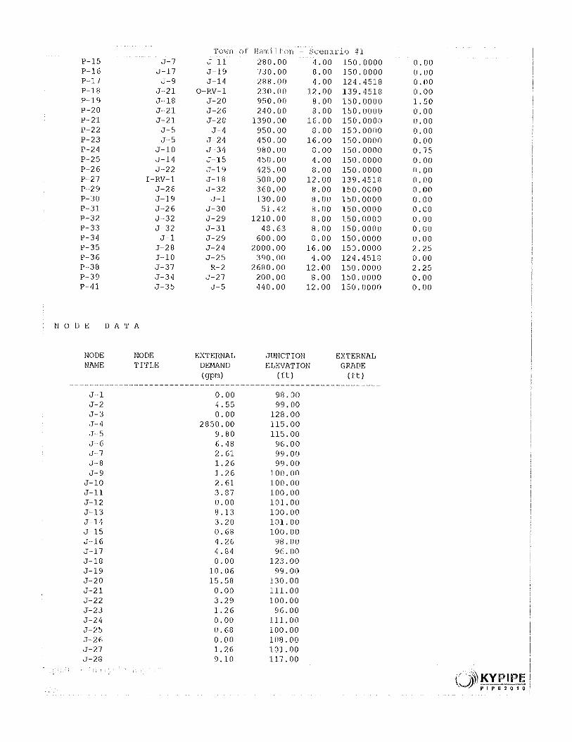
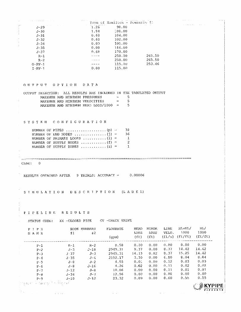
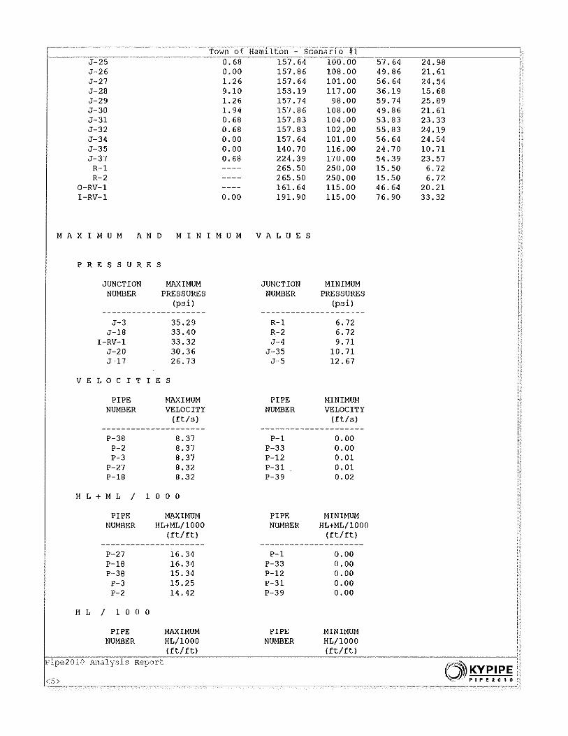
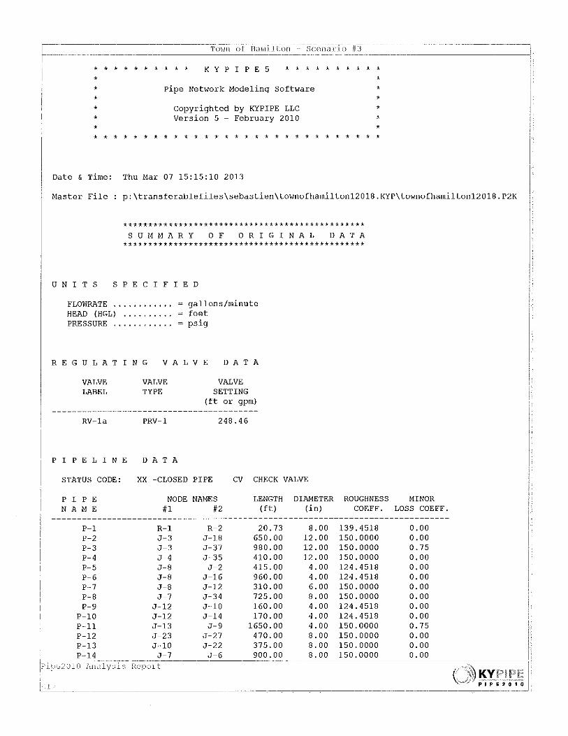
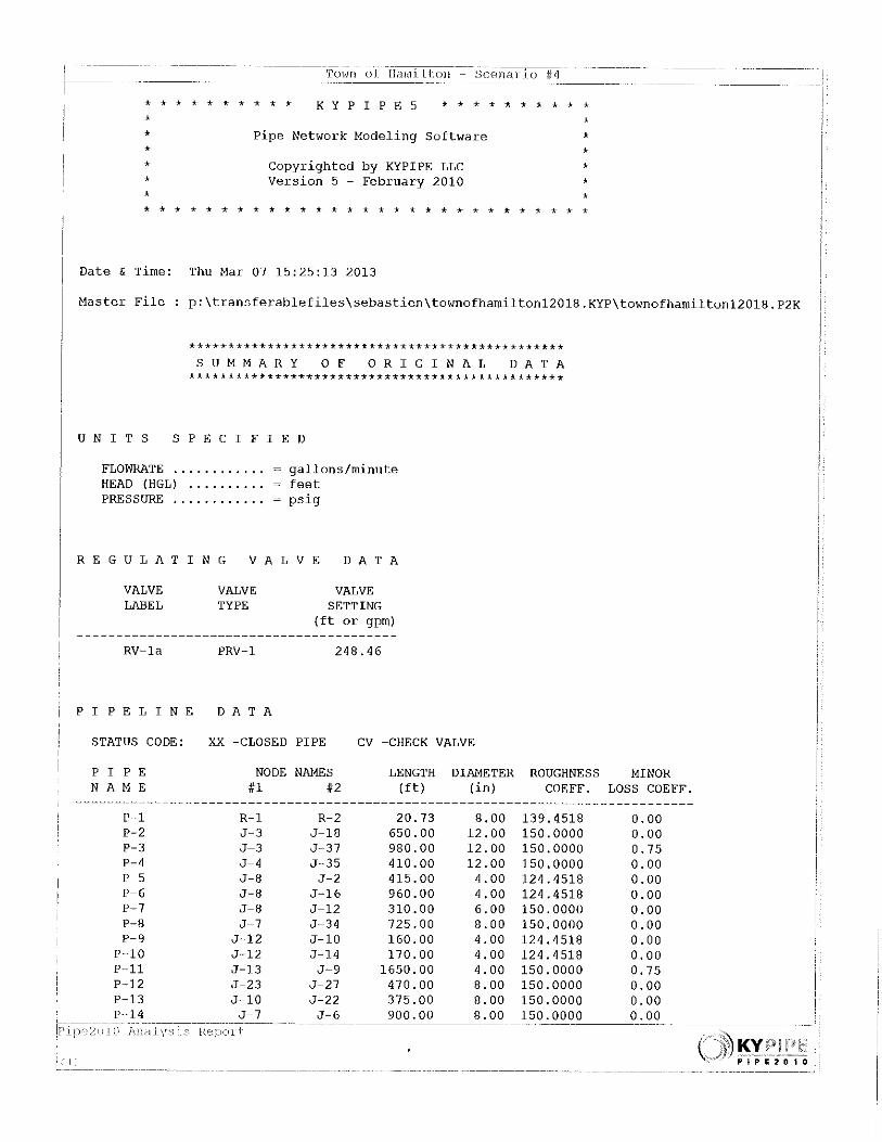
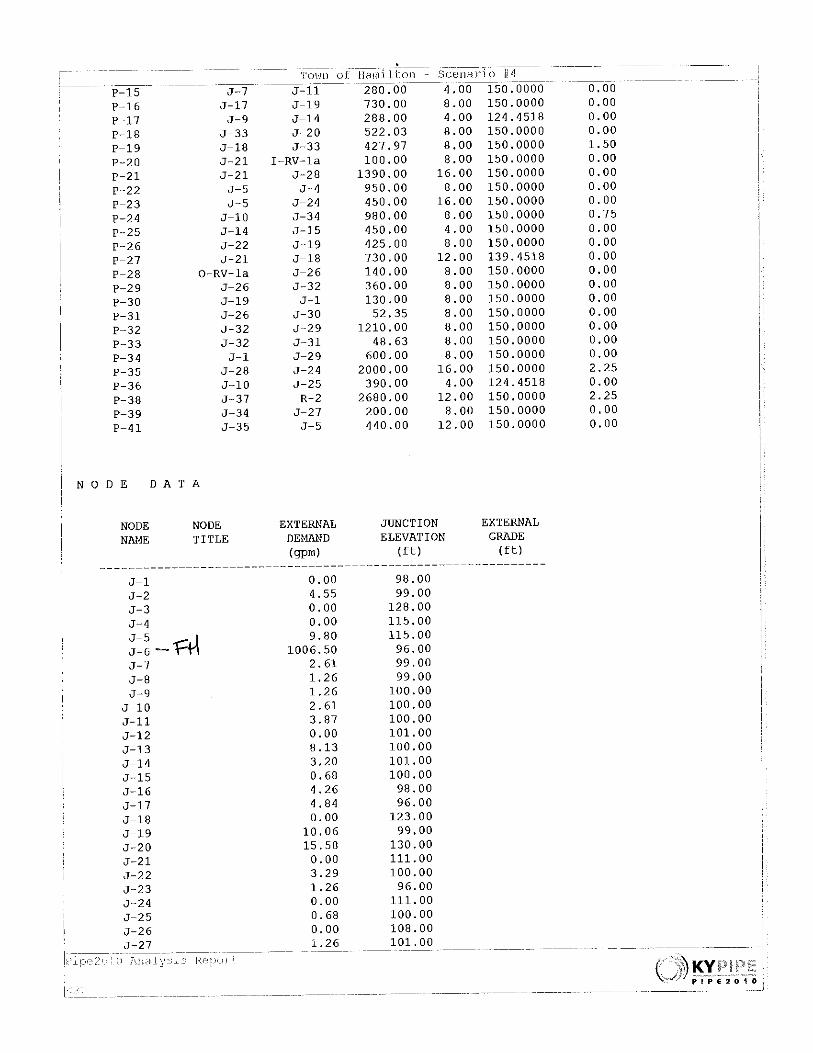
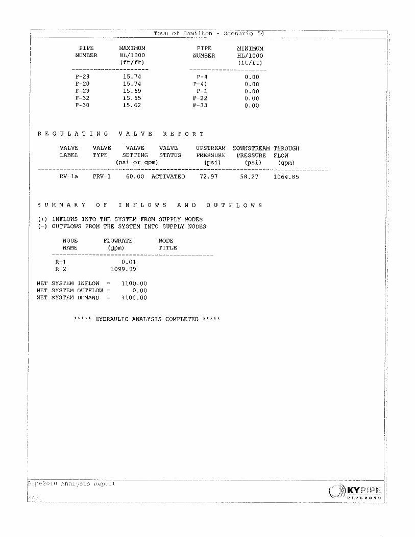
1.8 Conclusions The present water system facilities are sufficient to meet the needs of the Town for maximum day and peak hour demands for 184 ERUs through the year 2032. Growth, for planning purposes, has been projected at 6 new residential services to the existing town retail service area by 2018, and 20 new residential services by 2032. In addition, Janicki plant is expected to reach full development within the next 6 years (to 30 ERUs). In addition, the Town can serve upwards of 279 total ERUs with the system’s existing source and storage facilities. However, we recommend that the Town begin planning for a second source of supply. With only one well, the Town & Janicki Industries have some risk of running out of water if/when the well pump or well itself fails. At a minimum, we recommend purchasing a 10hp replacement well pump to have on hand for back-up. Additionally, the Town should budget for the development of a 2nd source. The evaluation of the system’s distribution capabilities with projected demands shows that fire flows are beyond requirements with the exception of the Janicki Plant area (northwest of the water retail service area). Relocating the PRV from the north side of SR 20 to the south side of SR 20 will allow the full head in the reservoirs to be available for fire flow for the Janicki plant. See chapter 4 for more details.

14
Future line extensions and loops will continue to improve the distribution system and meet and maintain fire flows as maximum day demands increase. Fire protection of 1000-gpm is adequate under existing state and County requirements and should be adequate in the future based on the proposed Skagit County Land Use Plan for the residential zone within the Town retail service area. Improvements to the system to provide for new services (including developer extensions) will be designed to meet the required fire flows as domestic and commercial demands increase.
1.9 Ownership & Management
Town of Hamilton 584 Maple Street PO Box 528 Hamilton, WA 98255 Phone/fax: 360-826-3027 E-mail: [email protected] The Town elected officials are listed below: Joan Cromley- Mayor 613 Shiloh Lane Sedro-Woolley, WA 98284 E-mail: [email protected] Telephone: 360-826-4953 (home) / 360-840-9144 (cell) Ruth M. McDermott - Councilmember #1 401 Maple Street Hamilton, WA 98255 E-mail: [email protected] Telephone: 360-333-7996 Jennifer Benjamin-Councilmember #2 PO Box 71 Hamilton WA 98255 E-mail: [email protected] Telephone: 360-826-6644 (home) / 360-610-0220 (cell) Bethany Henderson -Councilmember #3 PO Box 31 217 South Street Hamilton, WA 98255 E-mail: [email protected] Telephone: 360-770-0080 Andrew Jensen- Councilmember #4 P. O. Box 57 Hamilton WA 98255 Telephone: 360-826-4733 (home) / 360-391-2954 (cell)

15
P. Richard Moore- Councilmember #5 P. O. Box 432 Hamilton WA 98255 E-mail: [email protected] Telephone: 360-929-1015 (cell) The Town clerk is: Susan West-Mani 33827 SR 20 Sedro-Woolley, WA 98284 E-mail: [email protected] Telephone: 360-826-3919 The Certified water operator is employed by contract. The current operator is: Kathleen “Cas” Hancock Cas Hancock and Associates 46451 Baker Loop Road Concrete WA 98237-9558 E-mail: [email protected] Telephone: 360 770 4633 Certification # 007482, WDM 2, BTO and CCS

16
Chapter 2: Service Area Description
2.1 Introduction This chapter describes the Town of Hamilton Water Department’s existing and future water retail service areas and water service agreements.
2.2 Location and Surroundings The Town of Hamilton is a rural community located in Skagit County adjacent to State Route 20 and the Skagit River. The retail service area includes Sections 11-14 in Township 35 North, Range 6 East. The Town owns and operates a potable water system, which currently serves a population of approximately 548 through 109 residential, 22 RV (served by 6 meters) and 9 non-residential connections (includes the 200 Janicki employees). The Town of Hamilton is located within the Skagit County Critical Water Supply Service Area. As such, Hamilton's Water System Plan is required to meet all legislated service area identification requirements of the Skagit County Coordinated Water System Plan developed under the State of Washington Water System Coordination Act. Hamilton representatives, as members of the Skagit County Water Utility Coordinating Committee, participated in revision of the County's Utility Service Review Procedures and identified a water service area boundary for Hamilton as part of the 1999 Skagit County Coordinated Water System Plan (CWSP). The area is predominately rural and is a mix of wooded areas and open fields. The elevation of the retail service area ranges from 95 feet along the Skagit River to 125 feet along the State Highway, on the north margin of the retail service area. Several small wetland areas exist within the water system boundary. The water system currently serves approximately 548 people with 124 service connections (2012). The retail service area of the Town consists primarily of single-family homes and a limited number of commercial connections, most of which are located within the floodway. All the residential connections are considered full time. It is understood that among the existing 124 connections, 123 were located within the current Town retail service area boundary, and one outside (Parcel # P41080 – see full size map #9 in Appendix VIII for location). It is understood that this lot has been served and has paid the water fees since 2002. At the time of original connection of the above referenced property to the Hamilton Water System in 2002, the Town Council agreed to waive the normal hook-up and connection fees and charges in return for easement and construction of the water system transmission line through the above mentioned property. The lot owners and the Town have agreed to include the property in the Town retail service area using this Water System Plan update (see agreement letter signed by both parties in Appendix V). A consistency statement based on the updated retail service area including the subject lot and provided by Gary Christensen from Skagit County Planning Department is included in Appendix V.
Map 9 - Water System Map in Appendix VIII

17
2.3 Town Service Area Zoning and Skagit County Land Use The land use zoning within the Town retail service Area has been defined by the Board of Skagit County Commissioners as Incorporated areas and Commercial/Industrial within the Urban Growth Area. There are also two pieces of land defined as Hamilton Residential and Hamilton Urban Reserve north of State Route 20 to allow the Town to eventually move out of the floodplain in the future. See maps 2, 3, 4, & 5 in Appendix VIII. Future land use is expected to follow existing patterns and the zoning currently in place, based on Skagit Planning Department projections. Please see maps 2, 3, 4, & 5 in Appendix VIII which presents the relevant section of the Current and Future land use map prepared by Skagit County for the Town of Hamilton area. After numerous flooding incidents, a number of properties were purchased by Federal Emergency Management Agency (FEMA) funds and can no longer be used as building sites for residential or commercial uses. See map 1 in Appendix VIII.
Map 1-Flood Warning Map for the Skagit River Valley (See Appendix VIII) Map 2-Skagit County Comprehensive Plan Designations and Zoning Districts Map (See Appendix VIII) Maps 3 & 4 -Town of Hamilton Retail Service Area (See Appendix VIII) Map 5 – Town of Hamilton Urban Growth Area (See Appendix VIII)
2.4 History The Town is primarily a residential community with a limited business area. The majority of the retail service area is located south of State Route 20, within a relatively flat floodplain just north of the Skagit River. Within the retail service area, land slopes gently to the south and west toward the river. Elevations are generally between 90 and 125 feet above mean sea level (AMSL). The Town was originally founded as a series of homesteads with accompanying water rights filed under the 1881-1889 Homestead Act. When the Seattle Northern Railroad came to Hamilton in 1891, the Town was incorporated with a population of 327. In 1935 a new 20-ft well and elevated 4,000-gallon storage tank were constructed to serve the Town. At the same time, the Town began acquiring private water rights. In 1978, the Town reached a maximum of 174 service connections. In 2012, approximately 548 customers were served through 124 connections (including Janicki employees). The Town experiences regular flooding, and the flood of 1980 prompted construction of a new well and 65,000-gallon reservoir. In 1982, the Town acquired the current water rights (certificate G1-24051C) for this well. In 1993, the installation of a new 8-inch water line allowed for the Town to expand north of State Route 20. Mo r e r ecently, the Town extended the corporate limits and the retail service area to include additional land north of State Route 20 with the intention of gradually shifting growth and development to this higher elevation. I n 1997, the well was classified as a “Groundwater Under the Influence of Surface Water” (GUI) source and the Town was required to consider installing filtration treatment or relocating its source of supply. In 1999, the Town drilled a new production well about one mile north of the existing well. The new well is located outside of the floodplain at an elevation of

18
approximately 250 feet. Switchover to this new source occurred in December 2002 following the construction of the chlorination and greensand filtration facilities that were required to treat elevated levels of manganese. While manganese is not a health threat, it is of esthetic concern and treatment techniques were developed. Chlorination with sodium hypochlorite followed by manganese greensand filtration (106 gpm capacity) was provided. A sufficient dosage of chlorine was added ahead of the treatment system to oxidize the iron and manganese, as well as carrying a residual through the reservoir and to the extreme ends of the distribution system. Sediments in the backwash water from the filters are allowed to settle out, and the water is recycled to the treatment system. This system is currently being bypassed with permission of the DOH to avoid having the cost of a special classification of operator. Along with the treatment facilities, a 290,000 gallon concrete reservoir (55 ft high and 30 ft in diameter) was installed at the well-site. The overflow elevation of the reservoir is 305 feet. With annexation of the Janicki Industries (JI) property (formerly Crown Pacific property) in 2007, a second similar 290,000 gallons of storage was constructed next to the first one to provide adequate fire-flow. In addition, addressing concerns for impact on Little Carey’s Creek, a year-round fisheries habitat that flows near the well site, a fisheries mitigation program was developed by the Town and Washington Department of Fish and Wildlife (WDFW), which was accepted by the Washington Department of Ecology and 30 gpm of water rights (Gl-28066A), were issued to implement the plan. A 2-inch diameter pipeline was constructed from the well/mitigation tank site to the vicinity of the springs, and when the flow in Little Carey’s Creek drops below an agreed rate (during the months of May through October, as measured at a WDFW stream gauge), the Town provides additional water flow to the springs through the 23,500 gallon mitigation reservoir and pipeline (only un-treated water is provided for fish mitigation). The mitigation flow rate is 1 gpm (or 1,440 gallons per day) for fish mitigation for each 10,000 gallons per day of water sent to the Town’s distribution system. For example, if the Town’s usage is 30,000 gallons per day, the continuous rate of flow through the fish mitigation pipeline would be 3 gpm (fisheries mitigation applies May through October). The daily demands are routinely determined and fish mitigation flows are adjusted accordingly and recorded on a daily basis. See Little Carey’s Creek Water Right Mitigation Plan in Appendix VI and Typical Stream Mitigation Daily Log in Appendix VII. There are historical records for three earlier efforts for Water System Planning: Group A Comprehensive Water System Plan was prepared for the Town in the years 1994 and 2002. An Amendment to the Group A Water System Plan was prepared in 2007.
2.5 Population Growth, for planning purposes, has been projected at 6 new residential services to the existing Town retail service area by 2018, and 20 new residential services by 2032. This projection was based on growth from 1990 to 2000, the number of vacant properties available within the system boundaries, and Skagit County growth projections for the Skagit area. The commercial connections are expected to stay the same except for the Janicki plant which is expected to reach full development within the next 6 years (to 30 ERUs). The basis for these projections has been discussed among the Town Council and it was agreed that one new residential connection per year is a reasonable assumption based on past experience and their knowledge of the community.

19
Some of the assumptions made include the following:
Zoning will not change during the 20-year period Growth will continue at a rate similar to the last 10 years Slower growth in the floodplain will be offset by growth at the higher elevations Water service area will expand to the north of SR 20. No major development will take place north of SR20 during the 20-year period. Shangri La Community Club Water System will not be annexed by the Town during the 20-
year period.
If any of these assumptions are changed, the projections of future service connections should also be modified to reflect the changes. Calculations for ERU’s, Storage, and Water System demands will be updated as necessary to adequately represent the number of new connections added to the Town.
2.6 Topography and Geography The Town of Hamilton retail water service area includes the upland areas of Shiloh Lane (north of State Route 20) and the portions that lie outside the floodway (south of State Route 20) and the Town proper. The retail service area includes steep slopes along low bank portions of the shoreline of the Skagit River and the lowland floodway to the east and west. The topography rises from 90 to approximately 125 feet northeast of the State Highway. Several wetland areas are found within the retail service area. The old growth timbered lands were all logged off in the mid 1800’s and were converted to the Town site and residential home sites with some vacant parcels and several farms.
Map 6 -USGS Topographic Map (See Appendix VIII)
2.7 Climate The Town of Hamilton is in the Pacific Mountain Climate Zone. Hamilton experiences a mild climate with few extremes in high and low temperatures. The average daily temperature varies from 31 degrees in January to 77 degrees in August. The average annual precipitation in the Town of Hamilton is approximately 67 inches, mostly occurring from October through June.
2.8 Proposed Development Projects The Town’s existing retail service area is shown graphically in map 7 (See Appendix VIII). There are several problem private wells within the Town’s retail service area on Bella and Division Streets, as well as two small residential areas that could be annexed in the future:
Shangri La Community Club Water System # 77486U- 65 approved connections Punkin Center- 25 residential connections served by individual wells
The residential development of Shangri-La is a plat with 65 approved connections located along the north bank of the Skagit River just east of Hamilton. This community currently operates their own well, although flooding is a recurring problem. The Shangri La Community showed some interest in joining the Town of Hamilton Water System a few years ago but made repairs and do not lean toward that direction anymore. The Punkin Center residents have not expressed interest but the changing climatic conditions may require this move in the future. These annexations are

20
unlikely to happen during the next 20 years and are not part of the 20-year forecast for the Town. The Water System Plan will be updated if either of the projects move forward.
Map 7- Proposed Development Vicinity Map (See Appendix VIII)
2.9 Water Service Area Agreements All water purveyors located within a Critical Water Supply Service Area (CWSSA) are required to have a water service area agreement that identifies the external boundary of their water service area. The Town of Hamilton was incorporated into the Skagit County Coordinated Water System Plan of 1999. The Town’s current retail service area (including parcel # P41080) was approved by Skagit County.
Maps 3 & 4 -Town of Hamilton Water Service Area (See Appendix VIII)
2.10 Retail Service Area Policies
Retail service area Policies directly or indirectly affect the provision of water service to Hamilton customers. These defined policies have accumulated over the years and are designed to guide the growth of the system and establish how the Town will respond to requests for water service within the water system retail service area. An extension of service must be in accordance with the Skagit County CWSP (1999). The cost of water distribution mains, fire hydrants, and a portion of the cost of general facilities will be paid for by the owners of the land that is being benefited. Additional details about system extension policies are described in Ordinance No. 297 (see Appendix II). Conditions of Service address specific requirements that facilitate the implementation of the Town's service area policies. These conditions, which are formalized in the Ordinance, must be met prior to an applicant receiving water service. The Hamilton water system is not interconnected in a manner to enable it to wheel water to other entities. There are no interties between the Hamilton water system and adjacent systems. General Water Service Policies adopted by the Town are as follows: General Facility charges- The Town has a nominal charge for new water service connections. This is discussed in Chapter 7 Financial Program. Cost Recovery and Late Comers- Water system extensions constructed by a developer sometimes have the potential for other customers to connect for water service. The Town allows for the creation of a late comers/cost recovery contract with an eligible Developer who may construct a new water main across or along properties that are not involved with the Developer’s work. New water customers that connect to the new water main may be subject to the late comer/cost recovery contract. These cost recovery contracts are subject to review by the Council, and equitable distribution of the costs and benefits of the proposed water main extension. Requests to create a late comer/cost recovery contract must be submitted by the Developer to the Town before construction begins, outlining the preliminary construction costs and plans. The Town will develop the final benefit area, cost allocation to properties, recording of the contract with the county clerk, hold a public meeting, and charge the Developer direct costs related to administration of the contract.

21
Surcharges for Water Service Outside of the Corporate Limits- The Town does levy a rate or fee surcharge against water customers outside of the Town’s corporate limits. New Construction Standards and Requirements - The Town’s construction standards, as well as the Policies and Procedures for Developers, are presented in Chapter 8 of this document. Requirements for cross connection control devices, inspection, testing and new water services can be found in the Town of Hamilton Water Service Ordinance #297, provided in Appendix II. Urban Growth Area- All of the Town system is within its own Urban Growth Area (UGA). Wholesale and Wheeling Water Supplies The Town does not maintain interties with neighboring systems; this precludes the possibility of buying, selling, or wheeling water. The Lyman water system is the closest municipal system, located approximately 4 miles west of Hamilton on the north bank of the Skagit River. Skagit County Water No. 1 (Birdsview Water System) is situated approximately one mile to the east of Hamilton's r e t a i l service area. The residential development of Shangri-La is a plat with 65 approved connections located along the north bank of the Skagit River just east of Hamilton. This community currently operates their own well, although flooding is a recurring problem. Punkin Center is a development located just north of Hamilton with 25 residential connections served by individual wells. The prospective Centennial Annexation development is located northeast of Hamilton. This area is currently undeveloped and without a water source. There are also several individual problematic wells located both within and outside of the Town retail service area boundaries. The Town is open to regional planning efforts, and will consider actions that are consistent with State and regional goals, and those that protect the rate payers and customers of the Town, as well as the aquifer that it uses for supply. Priorities for New Water Service- the Town’s water source supply is limited by the water rights as delineated on page 3. The Town grants new water meters for individual new service and water connection and water facilities improvements for commercial and residential construction. Town Financial Participation in Developer Extension- the Town may participate in cost sharing and contribution with a new Developer Extension which will convey the improvement to the Town for ownership and operation. The amount of participation by the Town will be based upon the proportion of benefit to the Town (such as pipeline over sizing) as well as the availability of Town funds and will be in accordance to the State Revised Code of Washington and Town procedures. New Water Service Requests- the Town will consider all new water service requests from residents, property owners, or for parcels that are located within, or partially within, the Town’s retail service area. The Town may consider new water service requests for parcels outside of the Town’s retail service area if the request is consistent with the Town’s policies, and consistent with county and regional agency policies, and adjacent utilities. New water service will be reviewed for consistency with local land use plans and county development regulations. Issues of inconsistency or conflict will be referred to the applicant and the county for resolution before a water service request is processed. New water service requests will be considered by the Council as well as other information when evaluating new water service request(s).

22
New water service is available to the extent of available, unallocated water rights for the new service. If the application for new water service exceeds the unallocated water rights for the Town’s sources, the applicant must investigate a new water source supply and may be required to develop additional source capacity. New water service will be subject to the policies and procedures of the Town, to the requirements for new construction, subject to payment of all fees, charges, and obtaining permits and water rights where applicable and construction of the required system improvements or new water mains. Duty to Serve Requirements- the Town commits to provide water service to all new connections within the retail water service area when the circumstances meet the four threshold factors listed below:
1. The Town has sufficient capacity to serve water to the customer in a safe and reliable manner.
2. The proposed service request is consistent with adopted local plans and development regulations.
3. The Town has water rights capacity (or sufficiency) to serve the proposed service request.
4. The Town commits to provision of water (or deny availability of water supply) to the proposed service request in a timely and reasonable manner.
New water service will not be denied without cause and will be based upon the four threshold factors as listed above and compliance with the Town’s development standards. The appeals process established in the Skagit County Coordinated Water System Plan is available for use by applicants.
Annexation- the Town of Hamilton does not have a formal annexation policy. In practice, if properties are annexed, the annexed property owners pay the costs of expanding the water facilities. Connection fees are charged in addition to the cost of system expansion. (See Appendix II- Ordinance 297, Chapter 13.28) Annexation of properties is currently limited to properties within the retail water service area boundary.

23
Chapter 3: Existing System
3.1 Introduction The previous chapter described the areas served by the Town of Hamilton water system. This chapter will detail the system components and how water is supplied, distributed and stored. The Town’s system consists of a distribution grid and transmission mains along with two 290,000 gallon above ground concrete storage reservoirs. Water is provided to the system from one well that is controlled by the water level in the main storage tank. The system is divided into 2 pressure zones, #1 and #2, to provide acceptable working pressure at all elevations throughout the retail service area. The map #9 (See Appendix VIII) shows the Water System as well as the storage tanks and well location. The following sections inventory the system’s existing facilities. The Town’s well source (SO2) is located on property that is owned by the Town.
3.2 Source The Town obtains all of its water from one well within the study area. The wellhead protection plan for the Town is included in Appendix XIV. The existing well is currently capable of supplying the total authorized Qa of 100.86 acre-feet per year for domestic/industrial usage and 36 acre-feet per year for the Little Carey’s Mitigation Plan.
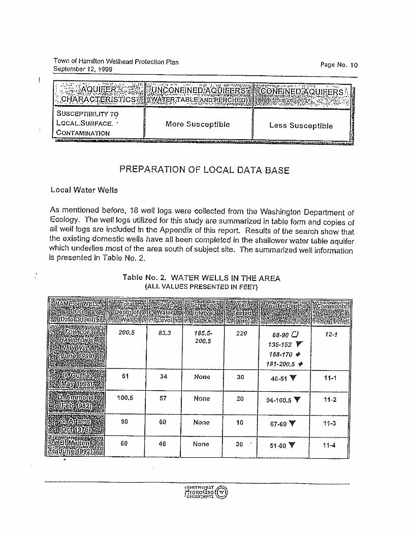
3.2.1 Well S02 The well was drilled in 1999, as an 8” diameter steel casing to a depth of 200.5 feet. There is a 20
foot segment of stainless steel “Johnson” brand Screen with a slot size 60. The Well static water level is at 83.3 feet below top of well. The well penetrates an aquifer that was test pumped under the supervision of Associated Earth Sciences (AES), who estimated that the well is capable of producing 525 gpm (AES’s Well Completion Report is included in a September 1999 Project Report Update for Water Production Facilities produced by Wilson Engineering). Water rights have been issued for a total of 136 gpm, including 106 gpm for municipal purposes and 30 gpm for fish mitigation (Water Rights are enclosed as Appendix IV). A 10hp submersible pump capable of delivering 136 gpm has been installed. An automated control system restricts flow to the Town’s distribution system 106 gpm; the balance of the flow is diverted to a mitigation tank adjacent to the Town’s storage reservoir. The Town holds water rights from one source as seen in the summary of this WSP. Well S01 is no longer in use, and its water rights have been transferred to Well S02.
Picture 1- Well S02 in treatment house

24
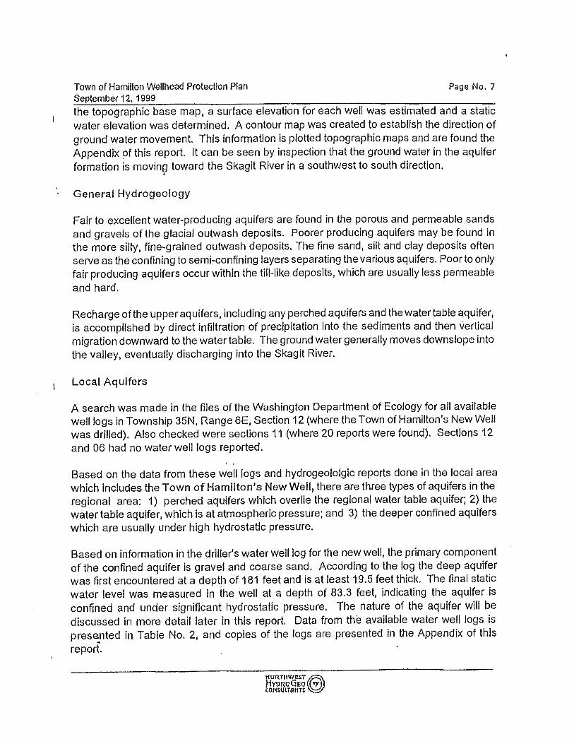
3.2.2 Monitoring Well A preliminary permit was issued by the Department of Ecology (DOE) to the Town in 1999 as part of the Change of Use application for Water Right Certificate G1-2003C. The purpose of the preliminary permit was to determine if water was available to transfer another Water Right Certificate to the new well and to estimate the impacts of that withdrawal to Little Carey’s Creek. During drilling of the production well, a shallow unconfined aquifer was encountered and DOE required drilling of two monitoring wells (one shallow, one deep) as part of the preliminary permit to gather data for the aquifer test concerning the production well’s influence on the Carey’s Lake- Carey’s Creek-Hamilton Slough drainage system. No data was able to be gathered from the shallow well and it was abandoned. Monitoring of the deeper well was used to estimate the impacts of production well withdrawal. The data collected did indicate that the new well is recharged when production well pumping occurs. It was concluded that the leakage is likely being supplied by the shallow unconfined aquifer. Provisions attached to authorizing the October 2000 Change of Use of Certificate G1-2003C include using production well meter reading and monthly recording of the static water level (SWL) in the observation/monitoring well to analyze the impacts to Little Carey’s Creek. The mitigation plan referred to in section 2.4 of this WSP Update was implemented based on this data. The static water levels in the monitoring well have inadvertently not been collected since operator changeover in 2007. Hard copies, if ever printed, of data do not exist and all computer files were erased before handover to a new operator. No mention was made that there were such requirements, only instructions about the seasonal use of the mitigation tank and stream weir readings. The data logging function has not been attached to the monitoring well since early 2008. Discovery of the data logging software was made in 2013. Re-connecting the electronics and monthly monitoring of the SWL and weir levels is the top priority for the Town. Detailed well logs can be found in Appendix XVII.
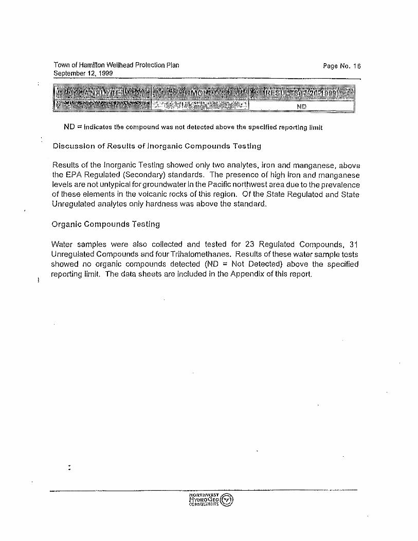
3.3 Water Quality The Town of Hamilton Water system monitors the system’s water quality in accordance with Washington State Department of Health (DOH) requirements and consistently meets or exceeds all testing criteria for primary contaminants. The Safe Drinking Water Act (SDWA) and its amendments have increased the monitoring requirements to include trihalomethanes, radionuclides, and Volatile and Synthetic Organic Compounds. The Town used chlorination and pressure filtration for treatment of iron and manganese from well SO2 until October 2010. Additional bacteriological analyses of non-treated water from the well are underway to provide data in support of eliminating the need for chlorination now that the filtration system has been disabled. These analyses of “raw” water show no contamination to date.
3.3.1 Radionuclides The Town sources are in compliance with federal radionuclide maximum contaminant criteria. Testing is done every 3 years and the last testing was in September 2010. See laboratory results in Appendix XV.

25
3.3.2 Volatile Organic Chemicals Testing is done every 3 years and the last testing was in September 2012. Since sampling began, none of the regulated chemicals have been detected. See laboratory results in the Appendix XV.
3.3.3 EDB & other fumigants The last testing was in September 2010. Since sampling began, none of the regulated chemicals have been detected. See laboratory results in the Appendix XV.
3.3.4 General SOC’s State waiver for general SOC’s.
3.3.5 Herbicides, Insecticides, & general pesticides. The last testing was in October 2005. Since sampling began, none of the regulated chemicals have been detected. See laboratory results in the Appendix XV.
3.3.6 Asbestos The Town distribution piping has asbestos cement walled pipe in use. Results of samples taken were within maximum contaminant levels and were last tested in August of 2009. See laboratory results in the Appendix XV. The Town is expecting to replace the last sections of asbestos cement pipe in use in the near future (see chapter 6 for more details)
3.3.7 Inorganic Compounds State guidelines require that the source water is tested for IOC’s once every three years. The Well source has high levels of manganese that were initially filtered to meet state DOH recommended levels for secondary contaminants. Manganese is classified as secondary and does not pose a risk to the health of those who drink the water. IOC’s were last tested in September of 2007. The Town received a waiver in 2010. Next testing is due in September 2013. See laboratory results in the Appendix XV.
3.3.8 Nitrates Nitrate testing is due each year. The last test for nitrates was in September 2012. Since sampling began, none of the regulated chemicals have been detected. See laboratory results in the Appendix XV.
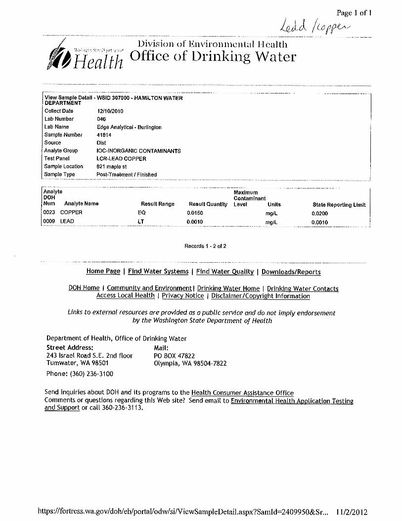
3.3.9 Lead and Copper The Town completed both initial rounds of lead and copper sampling in accordance with the EPA regulations. They were within maximum contaminant levels and were last tested in December of 2010. A copy of the Lead & Copper Monitoring Plan and several test results are provided in the Appendix X.
3.3.10 Bacteriological

26
Samples taken for coliform bacteria are collected at several sites throughout the system monthly. A copy of the Coliform Monitoring Plan and several test results are provided in the Appendix X.
3.3.11 Total Trihalomethanes and Halo Acetic Acid 5s The Town is required to monitor the disinfection byproducts in the water following the Disinfection Byproducts Monitoring Plan found in Appendix X. Since sampling began none of the regulated chemicals have exceeded the maximum contaminant levels and were last tested in July of 2012. See last laboratory results in the Appendix X.
3.4 Source Treatment
Picture 2 - Treatment house
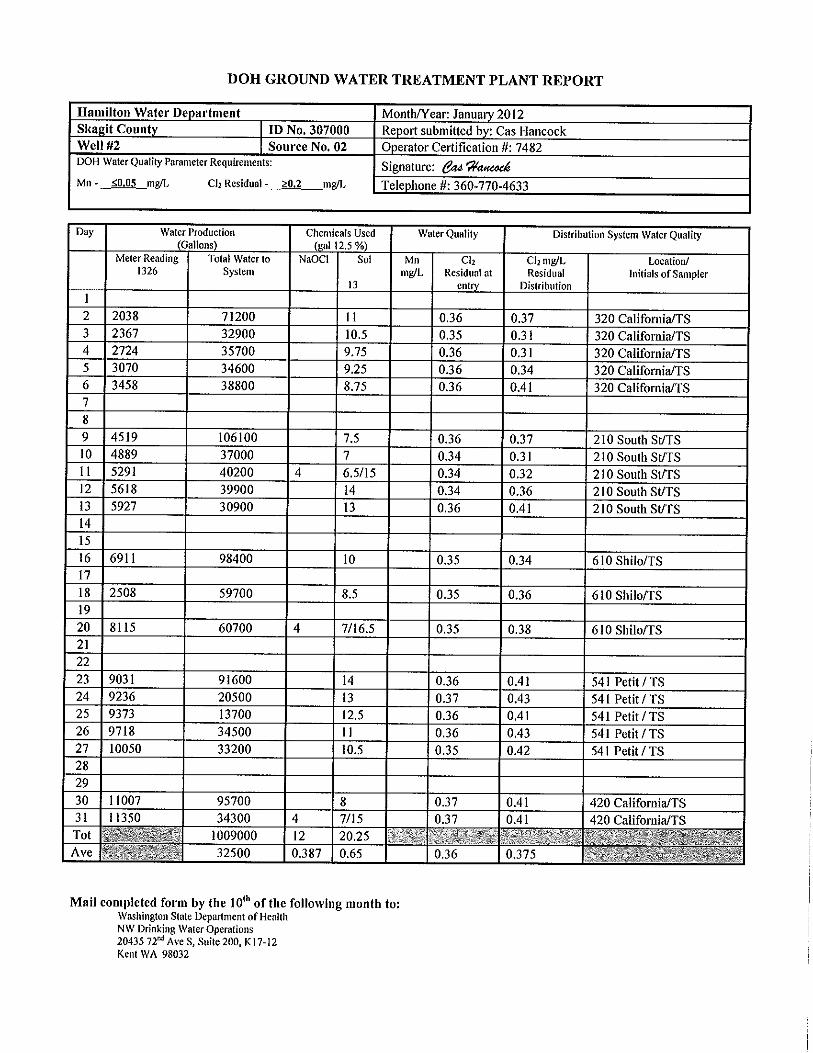
3.4.1 Disinfection Well SO2 is treated with sodium hypochlorite to prevent microbial contamination. Sodium hypochlorite is first added to the water in the treatment house before entering the reservoirs and then added through a flow-proportional post chlorination system on the discharge side of the reservoirs to ensure that a free chlorine residual of at least 0.20 mg/L is maintained in the distribution system See DOH Ground Water Treatment Plant Reports for 2012 in Appendix XVI.
3.4.2 Iron and Manganese Treatment In 2009 the Mayor asked the DOH staff to assist with exploring options to reduce the exorbitant cost to the Town for operation and treatment. The DOH Engineer for Skagit County and the Town made an agreement to monitor manganese levels in both the raw (untreated) water and the finished (treated) water for 1 year. Based on the data collected and customer input, on October 13, 2010 the Town Council voted to discontinue operation of the manganese greensand filtration equipment, thereby saving the Town approximately $30,000 per year in Operator/operations costs. Although the source is currently not treated for removal of iron and manganese, the equipment is kept available for use should the Town decide the filtration process is necessary. When the

27
equipment is in use, the iron and manganese is oxidized with hypochlorite followed by pressure filters. The treatment process uses two-30-inch diameter pressure filters assembled in a parallel process train. The treatment equipment is housed in the Town’s control facility, which is a cement block building at the well site with the dimensions of: 24 feet wide by 30 feet long. Sediments in the backwash water from the filters are allowed to settle out in a 4,000 gallon reservoir located in the treatment house and the water is recycled to the treatment system. Backwash solids are disposed outdoors into a concrete evaporation basin.
3.5 Distribution and Pressure Zones Since the Town’s well is not located within the distribution grid, there is approximately 3,800 lf of a dedicated transmission main. Distribution pipes throughout the system have service connections. The system is comprised primarily of 16”, 12” 8”, 6” and 4” pipe. Copies of the distribution system easements are attached in Appendix III. A copy of the Skagit County Franchise for operating the utility system within County rights of way is included in Appendix XXI. The Town has the following water main sizes and footages: 4” PVC 1,700 linear feet (lf) 4” Asbestos Cement 2,700 lf 6” PVC 800 lf 8” PVC 8,700 lf 12” PVC 6,000 lf 16” PVC 3,800 lf Total length of existing Water Mains is approximately 4.5 miles. The system also includes19 fire hydrants (not including the private fire hydrants located on the Janicki property), 9 blow offs, and approximately 10 water main valves.
3.5.1 Proposed Pipelines There are a few future projects that include installation of pipelines in the Town retail service area. The proposed pipelines are as follows:
Replacement of asbestos cement pipe along Cumberland Street (6-year planning period): Approximately 1,550 lf of 8” PVC
Replacement of aging pipe along Nolle Ave & creation of a loop (20-year planning periods): Approximately 2,000 lf of 8” PVC
8-inch water main looping along California, Maple and Petit Street (20-year planning period): Approximately 1,000 lf of 8” PVC
The amount of installed pipeline may vary, depending upon the order of completion. All water sold is metered at its point of use. There are the following meters in the system: (115) 3/4” residential meters (6) ¾” commercial meters (2) 1-1/2” commercial meters (1) 2” commercial meter

28
Note: RV parks are equipped with meters. Individual RV connections are not individually metered. See updated Water Facility Inventory (WFI) form in Appendix I (signed by Kathleen “Cas” Hancock, the certified water operator of the system)
3.5.2 Pressure Zones The system operates on gravity flow from the two main 290,000 gallon reservoirs located at the well site: Pressure zone 1 serves elevation areas above elevation 120’ foot north of SR20. Maximum water pressure in the zone is approximately 78 psi. Pressure zone 2 serves areas below 120’ elevation. Pressure ranges from 58 psi to 69 psi at 90 foot contour when the storage reservoirs are completely full. The 12” PRV station is recommended to be relocated south of State Route 20 between the 16” diameter Janicki waterline and the 8” Bella Street connections so that the full head in the reservoirs would be available for fire flow for the Janicki plant. See chapter 4 for more details.
See Map 9 - Water System Map in Appendix VIII for main sizes and infrastructure locations.
Table 1.3 -- Pressure Zones Zone 1 300’ HGL Shiloh Lane Gravity Service from Reservoirs.
Zone 2 250’ HGL Reduced Zone
(includes Janicki Property) (1)
Pressure Reduced Service from Zone 1 Reservoirs
(1) The Janicki property will switch from zone 2 to zone 1 once the PRV station is relocated from north to south of Highway 20 after the Janicki 16” pipeline connection. Individual PRVs may be required along the 16” pipe to keep the water pressure below 80 psi.
3.6 Storage
Storage is provided to the system by two 290,000-gallon Mount Baker cast in place concrete reservoir tanks located next to the well. The control facility, treatment system, and one reservoir were constructed in 2002. The second reservoir was constructed in 2008. The reservoirs are 55’ high and 30’ in diameter. Total water storage capacity is 580,000 gallons. Well S02 fills the reservoirs.
Picture 3 – Treatment house and concrete reservoirs

29
3.7 Control/Telemetry The main distribution reservoirs at the treatment facility site are filled by operation of well S02. The well pump is controlled by level sensors. Control panel at the treatment house shows:
Level of water in reservoirs If chlorination injectors are malfunctioning
The dialer at the treatment house is currently out of order and is expected to be replaced in 2013.
3.8 Operation & Maintenance Schedule
The Operation & Maintenance Schedule is provided in Appendix XXIII.

30
Chapter 4: System Analysis
4.1 Introduction This chapter describes the types of customers the Town of Hamilton Water Department serves and their historical water usage patterns.
4.2 Water Usage The population projections presented in Chapter 2 will be used in this analysis. The system serves primarily residential users. Commercial use is limited to 9 businesses at this time. Water use by Town residents shows seasonal variations. Water use is generally higher in the summer months due to outside water use and seasonal use by RV park visitors.
4.3 Historical and Existing Demands
The Hamilton water system is a completely metered system. As of September 2012, Hamilton serves 124 metered accounts. This is composed of:
109 residential meters serving 109 residences (109 ERUs) 6 residential meters serving 22 RV users (11 ERUs) (For purposes of this analysis, each
RV is estimated to represent 0.5 ERU). 9 commercial meters serving 9 commercial users.
Water usage records for the past 3 years were reviewed to obtain historical data on water system usage. (See exhibit IX for detailed water usage records) The first step was to evaluate the non-residential water usage in order to determine the total number of ERUs served by the water system. Table 4.3.1 – Number of ERUs served by system
Year
water usage for ¾”
residential water
meters (gallons)
Resid. Connec.
RVs served
by ¾”
residential
meters
Total ERUs
served by ¾”
residential meters
ADD for resid.
connec. (without water
losses) (1)
Total water usage –
Connection meter
readings (gallons)
Total number of ERUs served
by water system
Non-Residential
ERUs (2)
9/1/09-8/31/10 6,584,203 109 22 120 150 8,723,670 159 39
9/1/10-8/31/11 6,111,399 109 22 120 140 8,436,080 (3) 166 46
9/1/11-8/31/12 5,525,379 109 22 120 126 6,847,543 149 29
Notes: (1) Calculations in table 4.3.1 are based on the connection water meter readings. The calculated
Average Day Demand for the residential connections (ADD) does not take into account water losses in the water system.
(2) Non-Residential ERUs = Total number of ERUs served– Number of Residential ERUs

31
(3) Water usage lowered by approximately 800,000 gallons to take into account a large leak located after one of the ¾” commercial meters.
As of August 2012, the Town had 9 active non-residential connections serving a total of 34 ERUs. 2012 water usage readings are available for these connections, as summarized in table 4.3.2. Table 4.3.2 – Non-Residential Water Use Summary for 2012.
Meter type Water Usage
(gallons) (9/1/11 to 8/31/12)
Total number of ERUs served per size of water
meter (2)
¾” commercial (6 meters)
Bank building
190,187 4
Bar/Lounge Restaurant / Store
Post Office Frontier Telephone
Building Unimin Plant (1)
Lumber Shop 1-½” commercial
(2 meters) Janicki Lumber
467,979 10 Skagit Ready-Mix
2” commercial Janicki Plant 664,000 15 Total of non-residential ERUs 29
Notes: (1) Closed since May 2012 (2) ERU = Water Usage/(Residential ADD*366) = Water Usage/(123 gpd * 366 days) The Average Day Demand (ADD) and Maximum Day Demand (MDD) were determined using data collected from the source and connection meters and are summarized in Table 4.3.3. Table 4.3.3 – Water Usage
Year
Annual Gal.
Pumped from well
S02
Annual metered Cons.
(gallons)
Annual Unaccounted
/ loss (gallons)
ADD (gal/day/ERU) (include water losses in water
system)
MMAD- Max month average
day (gal/day/ERU) (include water losses in water
system)
MDD/ERU Calculated
via 1.7 x
MMAD (gal/day)
9/1/09-8/31/10 19,888,800 8,723,670 11,165,130 343 434 737
9/1/10-8/31/11 21,359,220 8,436,080 12,923,140 353 371 631
9/1/11-8/31/12
11,999,300 (1) 6,847,543 5,151,757 220 185 (2) 314
Design 290 (3) 475 (3)

32
Notes: 1. The Town’s annual water usage has been reduced from 21,359,220 gallons in 2011 to
11,999,300 gallons in 2012 while the number and type of connections were staying approximately the same (a 44% reduction in water use). This significant reduction in demand is a result of the following aggressive efforts to save water:
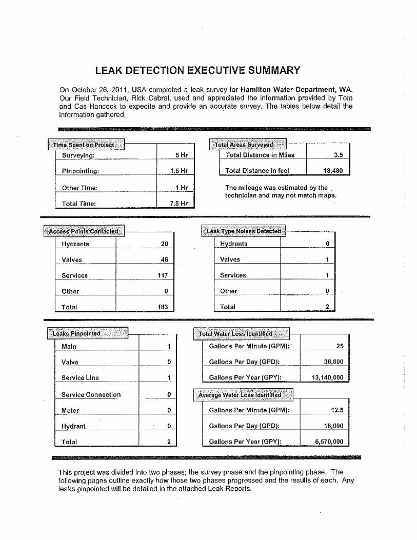
Find and repair leaks (Professional leak detection serviced the entire system in December 2011 - Survey Report in provided in Appendix XIX)
The PRV reduces excessive pressure in the older portion of the distribution system Installation of meters on all service connections (RV parks have a master meter,
individual RVs are not metered), Implementation of an increasing block rate structure intended to encourage
conservation Repair of leaks on private property Distribution of water conservation materials.
The annual volume of water pumped from the well is expected to decrease even more once we have a full year of data with the upgraded distribution system.
2. Most of the leaks were repaired by the end of March 2012, leading to a substantial decrease of
volume of water pumped from the well starting in April 2012. The Town has decided to use the month of August 2012 to calculate the MMAD for 2012 even if all the monthly water usages between September 2011 and March 2012 were higher because of the leaks (August was the month with the highest water usage in 2010 and 2011)
3. Using current information, it appears that an Average Daily Demand of 290 gpd / ERU and a
Maximum Daily Demand of 475 gpd / ERU are reasonable for future water usage projections (average of 2011 and 2012 figures). We understand that these numbers are very conservative as they are partially based on water usage readings dated before April 2012 (period of high leakage). These numbers should be updated for the next Water System Plan cycle or when the Town needs more approved connections with at least 2 full years of meter readings using the upgraded water system.
The use of these numbers would allow the system to serve additional connections; however a request for increased ERUs is not the purpose of this Water System Plan, nor is the Town seeking additional water rights at this time.
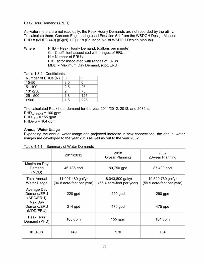
4.4 Water System Future Demands The approach used to calculate the projected system demand was first to determine the demand per connection for average and peak days. Based on historical usage, the system is expected to increase by 1 new residential connection per year over the next 20 years. Janicki plant is expected to reach full development within the next 6 years (to 30 ERUs). Future water use per ERU is expected to decrease if the Town goes on with its water conservation efforts. The ADD and MDD values should be updated after 2 full years of meter readings using the upgraded water system. Average Day and Maximum Day Demands ADD= 290 gpd/ERU MDD= 475 gpd/ERU Both numbers include water leakage.
33
Peak Hour Demands (PHD) As water meters are not read daily, the Peak Hourly Demands are not recorded by the utility. To calculate them, Garrison Engineering used Equation 5-1 from the WSDOH Design Manual. PHD = (MDD/1440) [(C)(N) + F] + 18 (Equation 5-1 of WSDOH Design Manual) Where PHD = Peak Hourly Demand, (gallons per minute) C = Coefficient associated with ranges of ERUs N = Number of ERUs F = Factor associated with ranges of ERUs MDD = Maximum Day Demand, (gpd/ERU) Table 1.3.2– Coefficients Number of ERUs (N) C F 15-50 3.0 0 51-100 2.5 25 101-250 2 75 251-500 1.8 125 >500 1.6 225
The calculated Peak hour demand for the year 2011/2012, 2018, and 2032 is: PHD2011/2012 = 100 gpm PHD 2018 = 155 gpm PHD2032 = 164 gpm Annual Water Usage Expanding the annual water usage and projected increase in new connections, the annual water usages are developed to the year 2018 as well as out to the year 2032. Table 4.4.1 – Summary of Water Demands
2011/2012 2018 6-year Planning
2032 20-year Planning
Maximum Day Demand (MDD)
46,786 gpd 80,750 gpd 87,400 gpd
Total Annual Water Usage
11,997,480 gal/yr (36.8 acre-feet per year)
18,043,800 gal/yr (55.4 acre-feet per year)
19,529,760 gal/yr (59.9 acre-feet per year)
Average Day Demand/ERU (ADD/ERU)
220 gpd 290 gpd 290 gpd
Max Day Demand/ERU (MDD/ERU)
314 gpd 475 gpd 475 gpd
Peak Hour Demand (PHD) 100 gpm 155 gpm 164 gpm
# ERUs 149 170 184

34
4.5 Supply The primary supply consideration is that the well and pumps, in coordination with the reservoirs, are able to meet the System’s peak hour and peak day demands. There are several factors to consider when calculating what the source capacity will be. They include the following: Replenishing Depleted Fire Suppression
For reliability purposes, supply sources should also be able to replenish depleted fire suppression storage within 72 hours while concurrently supplying the MDD of the water system (Chapter 7.1 of the WSDOH Water System Design Manual). To be clear, it means that if a fire were to occur during the summer (when the regular water demand is the highest), the Fire Flow Suppression Storage of 60,000 gallons protecting the Town should be replenished within 72 hours (FSS protecting the Janicki site is not included in our calculations). This is to help prevent running out of water if, for example, a second fire happens soon after the first one.
Water flow required to replenish depleted fire suppression storage within 3 days = FSS (Town) / (3 days) = 60,000 / (1440 x3) = 13.9 gpm.
Distribution System Leakage ADD and MDD values include distribution system leakage.
Water Right limits
The maximum annual volume to be pumped from the wells shall not be over the Water Rights limits as explained in table on page 3 (ADD criteria) The sources for a water system must be able to meet the water system’s Maximum Day Demand (MDD) (WAC 246-290-222(4)). (MDD criteria)
Thus, the source capacity will be:
Source Capacity – MDD criteria= ((Qs-13.9) x 1440 minutes) / (MDD) = (106-13.9) x 1440 / 475 = 279 ERU’s
Source Capacity – ADD criteria= Qa / (ADD x 365 days) = 32,865,375 / (290 x 365) = 310 ERU’s
Where Qs = Maximum Instantaneous Flow rate from well S02, (gallons per minute) Qa = Maximum Annual Volume (gallons) MDD = Maximum Day Demand, (gpd/ERU) ADD = Average Day Demand, (gpd/ERU)
Source Capacity – MDD criteria= 279 ERU’s Source Capacity – ADD criteria= 310 ERU’s Thus, the source is capable of the lower of the two methods or 279 ERUs.

35
Based on the growth projections in Chapter 2, the existing supply would meet all system demands through the year 2032. Redundancy
The Town has one well, 2 reservoirs and a partially looped distribution system. We recommend that the Town begin planning for a second source of supply. With only one well, the Town & Janicki Industries have some risk of running out of water if/when the well pump or well itself fails. At a minimum, we recommend purchasing a 10hp replacement well pump to have on hand for back-up. Additionally, the Town should budget for the development of a 2nd source. The system’s water supply characteristics can best be summarized as:
ground water source a limited, finite water supply requires careful management to preserve both quality and quantity
The Town has implemented a management plan for the protection of the existing ground water supply.
4.6 Water Quality Issues Issues of concern include manganese removal, Disinfection By-Products, SDWA amendments, and wellhead protection. The following is a discussion of the approach and criteria for each: The inorganic quality meets DOH requirements and the bacteriological tests regularly show lack of any contamination. The Town’s Water Quality Monitoring Schedule, Coliform Monitoring Plan, Disinfection By-Products Monitoring Plan, and Lead and Copper Monitoring Plan are attached in Appendix X.
4.6.1 Wellhead Protection Since the Town obtains all of its water from the well, protection of the source aquifer is critical to the long term viability of the system. The Town has prepared a wellhead protection plan (see Appendix XIV) and implemented the initial public education phase of the program in 1999.
4.6.2 Safe Drinking Water Act All required tests have been completed and the Town is in compliance with all requirements.
4.6.3 Manganese Water from the well showed elevated levels of manganese. Chlorination with sodium hypochlorite followed by manganese greensand filtration (106 gpm capacity) was originally provided. In 2009 the Mayor asked the DOH staff to assist with exploring options to reduce the exorbitant cost to the Town for operation and treatment. The DOH Engineer for Skagit County and the Town made an agreement to monitor manganese levels in both the raw (untreated) water and the finished (treated) water for 1 year (see Appendix XI). Based on the data collected and customer input, on October 13, 2010 the Town Council voted to discontinue operation of the manganese greensand filtration equipment, thereby saving the Town approximately $30,000 per year in Operator/operations costs. Prior to discontinuing the filtration system operation, sediments in the backwash water from the filters were allowed to settle out, and the water was recycled to the

36
treatment system. The greensand filters are currently backwashed monthly to prevent any accumulation of bacteria in the filter media. The filters may be re-activated in the future if the raw water manganese levels rise again. A sufficient dosage of chlorine is still added ahead of the storage system to oxidize the iron and manganese and carry a residual through the reservoirs; and an additional dose of chlorine is added as the water enters the transmission line to carry the residual to the extreme ends of the distribution system.
4.7 Power Supply The Town is dependent upon electrical power to pump water and the system vulnerability to power outages is considered moderate. Water is supplied to the system from the storage tanks by gravity, so short term outages do not impact the users; however, historically, the area has been without power for as long as eight days. A 25 kW Kohler propane generator is installed near the treatment facility as a back-up to run the controls and the well pump in case of a power outage. The generator automatically starts every Tuesday for 15 minutes (self-testing) to be sure it is operational.
4.8 Control The current automatic system provides the Town with efficient and effective control of the chlorine injectors and well production. The pump switches are set such that the tanks remain nearly full at all times (to 50’). Keeping the tanks full provides excess standby storage and helps maintain system pressures in all areas. The control system for the filters has been temporarily disabled and can be enabled quickly if the Town decided to re-instate operation of the filtration equipment. The operator currently manually activates the infrequent backwash cycles for the filters.
4.9 Distribution System Requirements The criteria used to determine the adequacy of the existing distribution system is based upon facilities designed to assure that pressure meets the Town distribution standard. During peak flow conditions, the pressure at each meter should be approximately 60 psi, and in no case lower than 30 psi. The distribution system must also be able to deliver the required fire flow during peak demand conditions at a minimum residual of 20 psi. A general rule in system design is that a looped system comprised of moderately sized mains providing multiple (or alternate) routes to any area is much more reliable and efficient than a system comprised of a few large mains. A looped system also increases circulation of the water, which minimizes poor water quality associated with stagnant water. The Town is currently implementing replacement of aging distribution system piping and is incorporating looping segments within the project. The current design standards, the Town’s Standard Specifications for Developer Extensions and the Town’s Water Policies are included in the Town Services Ordinance No. 297 in Appendix II.

37
4.10 Hydraulic Evaluation
4.10.1 Scenarios The existing water system was modeled using 2010 KY Pipe hydraulic modeling software to examine the system performance during peak hour consumptive demands, and also during fire flow conditions. Elevations are based on different previous documents by others and on Google Earth. Four scenarios regarding water use were analyzed. Please see below for more details on each scenario. For all the scenarios, we have made the following assumptions:
The model of the main Cla-val PRV is unknown. The Cv factor of 810 has been estimated based on manufacturer specification sheets for similar models.
All scenarios have been simulated with current development and water usage Scenario #1: Simulation of a fire event at the Janicki site with the main PRV station at its current location (north of SR20). A demand of 2,850 gpm has been added on fire hydrant J-4 in addition to the 100 gpm representing the Peak Hour Demand (PHD). The water level in the reservoirs is at elevation 265.5’ (Bottom of Fss for Janicki) Scenario #2: During PHD with the main PRV station relocated south of SR20. The reservoir is full, with a water level at elevation 300’. Scenario #3: Simulation of a fire event at the Janicki site with the main PRV station relocated south of SR20. A demand of 2,850 gpm has been added on fire hydrant J-4 in addition to the 100 gpm representing the PHD. The water level in the reservoirs is at elevation 265.5’ (Bottom of Fss for Janicki) Scenario #4: Simulation of a fire event on California Street with the main PRV station relocated south of SR20. A demand of 1,000 gpm has been added on fire hydrant J-6 in addition to the 100 gpm representing the PHD. The water level in the reservoirs is at elevation 292.3’ (Bottom of Fss for the Town) Figure 8 - Storage Elevations (See Appendix VIII)
4.10.2 Model Results & Analysis 1. Fire event at Janicki Plant:
Scenario #1 (main PRV station at its current location):
A demand of 2,850 gpm has been added on fire hydrant J-4 in addition to the 100 gpm representing the PHD. The pressures along the 16” diameter main are between 12 and 16 psi. The pressure at the fire hydrant J-4 itself is approximately 10 psi which is well below the minimum required pressure of 20 psi.
Simulation shows that the pressure drop through the PRV station is approximately 13 psi. This report recommends relocating the PRV from the north side of SR 20 to the south side of SR 20 so

38
that the full head in the reservoirs would be available for fire flow for the Janicki plant. See scenario #3 below and chapter 6 for more details. Note: The fire hydrants at the Janicki plant area are currently capable of approximately 2,500 gpm with minimum calculated pressure above 20 psi. See hydraulic analysis in Appendix XIII for more details.
Scenario #3: (main PRV station relocated south of SR20):
Fire hydrants at Janicki plant are all capable of at least 2,850 gpm with minimum calculated pressure above 20 psi. The maximum water velocity is approximately 8.4 ft/s under fire flow conditions. 2. Normal operations:
Scenario #2 (main PRV station relocated south of SR20)
During Peak Hourly Demand (PHD) with the main PRV station relocated south of SR20. The minimum pressure in the system will be approximately 56 psi under normal operations. The maximum pressure in the system will be approximately 82 psi under normal operations. All connections upstream of the main PRV station and below 115 feet should have PRV’s installed at their meters to keep operational pressure under 80 psi. 3. Fire Event in the Town:
Scenario #4 (main PRV station relocated south of SR20)
The pressure at the fire hydrant J-6 is approximately 26.2 psi. Fire conditions have been simulated at all the other hydrants in the Town and they are all capable of at least 1,000 gpm with minimum calculated pressure above 20 psi. Maximum water velocity is approximately 6.8 ft/s under fire flow conditions. A copy of the KY Pipe model input and output files are attached in the Appendix XIII.
4.11 Water Loss Distribution System Leakage (DSL) or water losses in the distribution system can be estimated by comparing records of volumes of water pumped, all authorized consumption, metered water treatment process water uses, and water sold. Table 4.3.3 summarizes the results of the water loss for 2010, 2011 and 2012. The Town installed water meters on all customer connections in 2006. Prior to 2006, there were no customer water meters and water use and losses were estimated. Customers paid a flat rate water charge prior to the year 2006. After meters were installed, the years 2006 through 2011 observed very high water losses or distribution system leakage. Acoustical leak detection service in December 2011 and aging pipeline/service line repairs in 2012 have significantly reduced the overall leakage rate. The Town monitors water usage records monthly to identify overall water usage and for distribution system leakage. Monthly DSL reports for 2011 and 2012 are included in Appendix XIX. This monitoring and evaluation effort is on-going.

39
4.12 Storage
4.12.1 Total Storage Capacity The reservoirs are 30’ Ø x 55’ tall for a total capacity of 580,000 gallons. The tanks are filled to a maximum of 50’. Thus, the total storage capacity (TS) will be approximately 527,272 gallons. TS = 527,272 gallons. The State Department of Health requires that all four storage elements be added together to calculate the total storage. Minimum design standards specify that the storage facility be sized to provide for the larger of standby storage or fire storage plus equalizing storage. The total storage (TS) requirement is also further modified by the Skagit County Coordinated Water System Plan to allow nesting of the fire suppression and standby storage volumes. Therefore, since FSS can be nested within storage volume, the larger of the two components (SB or FSS) is used to determine the TS. TS = DS + OS + ES + (the larger of either SB or Fss) Where: DS: Dead Storage
OS: Operational Storage ES: Equalizing Storage Fss: Fire Suppression Storage SB: Standby Storage
4.12.2 Dead Storage Dead Storage (DS) is the volume of stored water not available to all consumers at the minimum design pressure (WAC 246-290-230(5) & (6)) The highest connection served by the system is at 170’ of elevation and the highest fire hydrant served is at 130’ of elevation. The tank floor is at elevation 250 feet. The outlet pipe is going through the floor of the reservoir and has a 4” silt stop. With a minimum water level of 251 feet, the minimum pressure will be approximately 52 Psi at the highest hydrant and 35 Psi at the highest connection which meets DOH requirements for distribution system pressure. DS = 10,545 gallons.
4.12.3 Operational Storage The top 2 feet of the reservoirs is the operational swing between pumps off and call for the well on. This result is a total operational storage of 21,090 gallons. OS = 21,090 gallons
4.12.4 Equalizing Storage Equalizing storage must be provided for when the source pumping capacity cannot meet the periodic demands placed on the water system. Over a 24 hour period the supply and demand volumes should equalize. The volume of equalizing storage needed depends upon several factors including peak system demand, diurnal variation in system demand and the source production rate. Detailed daily variations in demand are not known for this water system.

40
Equalizing Storage is determined in accordance with the DOH Design Manual using Equation 9-1.
ES = (PHD-Qs) x (150 minutes), but in no case less than zero.
The ES equation compares the PHD with the source capacity. If PHD exceeds the source capacity (Qs), then an allocation of storage volume is made. The ES value has been calculated for the design years 2012, 2018, and 2032 which represents the current, 6-year, and 20-year design periods. The total Q from the well is 106 gpm. Peak Hour Demands (PHD) from Table # 4.4.1 (Page 32) are: PHD 2012 = 100 gpm, PHD 2018 = 155 gpm, & PHD 2032 = 164 gpm ES2012 = 0 gallons ES2018 = 7,350 gallons ES2032 = 8,700 gallons
4.12.5 Fire Suppression Storage Reserve storage for firefighting is necessary to provide large volumes of water for fire flow without disrupting service to customers. The fire flow requirements for the Town of Hamilton per Skagit County Code are the following: FF Storage for residential within UGA 1,000-gpm for 60 minute = 60,000 gallons FF Storage for Janicki Plant 2,850-gpm for 120 minutes = 342,000 gallons Fss = 342,000 gallons
4.12.6 Standby Storage Standby Storage is reserved to provide a measure of reliability should the well sources fail or if extreme water demands are experienced. Skagit County Coordinated Water System Plan allows consolidating standby and fire suppression storage which means that the Town can exclude the SB or FSS component, whichever is smaller, from the water system's total storage requirement. SB = TS-OS-DS- ES Thus, the standby storage available per ERU for the current, 6-year, and 20-year design periods are:
2012 SB (gallons) ERUs served
SB Gallons / ERU / day for
2 days 2012 495,637 149 1,663 2018 488,287 170 1,436 2032 486,937 184 1,323
Sometime after 2032 477,787 279 (maximum source capacity) 856

41
Table 4.12 - Summary of storage requirements (in gallons) Year 2012 2018 2032 Operational Storage (OS) 21,090 21,090 21,090 Equalizing (ES) 0 7,350 8,700 Standby (SB) 495,637 488,287 486,937 Fire Suppression (Fss) 342,000* 342,000* 342,000* Dead Storage (DS) 10,545 10,545 10,545 Total (TS) 527,272 527,272 527,272 *Skagit County Coordinated Water System Plan allows consolidating standby and fire suppression storage which means that the Town can exclude the SB or FSS component, whichever is smaller, from the water system's total storage requirement.
4.13 Review of Source, Storage and ERU Capability The existing water storage facility has sufficient capacity to serve the system through the 6 and 20-year planning periods. The ERU capability is summarized against the following components of the water system: Source Capacity – ADD criteria = 310 ERU’s Source Capacity – MDD criteria= 279ERU’s Storage Capacity > 279 ERUs

42
Chapter 5 Water Conservation Plan, Water Use Efficiency Program & Water Rights Analysis
5.1 Introduction The Town recognizes that water is a valuable and essential natural resource that needs to be used wisely. This water conservation plan provides an approach to increase water use efficiency within the Town’s retail water service area.
5.2 Background
5.2.1 State Conservation Planning Requirements The Conservation Planning Requirements published by the State Department of Ecology (Ecology) and State Department of Health (DOH) in March 1994 and 2009 Update, identify the water use reporting, forecasting, and conservation program requirements for public water systems. A water conservation plan meeting these requirements is a necessary element of a Water System Plan as required by DOH and is necessary to obtain water rights permits from Ecology. The Conservation Planning Requirements defines the necessary components of a water conservation plan as (1) water use data collection, (2) water demand forecasting, and (3) water conservation program. The planning requires the water conservation program to identify its goals and objectives, evaluate alternative conservation measures, and identify the selected measures including their schedule, cost, monitoring requirements, and estimated water savings.
5.3 Water Conservation Program As described above, the three elements of a water conservation plan are water use data collection, demand forecasting, and the conservation program. The water use data and system-wide demand forecasts are contained in Chapter 4 of the Town’s Comprehensive Water System Plan, and the conservation program is presented here. The Town will continue to collect water use data for evaluation of its conservation program and water use patterns, and for forecasting demands for future facility requirements. The following program includes a statement of the goals and objectives, an evaluation and selection of alternative conservation measures, the conservation program schedule and budget, and the method of program monitoring. The Town’s Emergency Response Plan is found in Appendix XII. (Includes Water Shortage Response Plan)
5.3.1 Conservation Program Goals and Objectives The goals and objectives of this water conservation program consist of:
Increase awareness among all water users of the value and importance of conserving water and of the methods available to achieve reductions in water use.
Reduce overall system withdrawal from the well. The Town will achieve these goals and objectives through the implementation of the water conservation program that follows.

43
5.3.2 Evaluation and Selection of Alternative Conservation Measures The Town’s evaluation of conservation measures and selected levels of implementation are presented below. Public Education School Outreach - This conservation measure is only required for larger systems. This measure requires educational programs that increase awareness of local water resources and encourage water conservation. Speakers Bureau This conservation measure is described in the Conservation Planning Requirements as “Seeking speaking opportunities and making speakers available to a wide cross-section of services, community and other groups.” The Town will encourage and make information available about upcoming water conservation speakers or meetings to their customers. As resources allow, the Town will strive to schedule speakers for their monthly Council meetings to discuss water conservation measures and benefits. Program Promotion This conservation measure is a required element of all water conservation programs. The planning requirements provide the following definition for this measure: “Publicize the need for water conservation through television and radio public service announcements, news articles, public water systems’ bill inserts, or other means. This includes promoting efficient indoor and outdoor water usage, distribution of conservation brochures, informing customers, builders and contractors of new plumbing code regulations requiring efficient plumbing fixtures, and other efforts.” The Town includes conservation brochures in water bills at the beginning of summer, which includes lawn watering calendars, and conservation tips. The Town also includes tips on water conservation and phone numbers for other conservation resources in the annual Consumer Confidence Report. See Appendix XX for the 2012 Consumer Confidence Report and for some samples of conservation brochures. Theme Shows and Fairs This measure requires that a portable display be made, along with educational materials to be exhibited at local fairs and theme shows. The Town will evaluate opportunities for more public education.
5.3.3 Technical Assistance Purveyor Assistance This item is described in the planning requirements as “assistance from wholesale suppliers to aide wholesale customers in developing and implementing conservation programs tailored to their needs, and in carrying out the wholesale suppliers’ conservation program.”

44
The Town does not have any current wholesale customers. Customer Assistance This measure is described as the utility providing “assistance and information to customers which facilitates water conservation.” A great deal of the information on water conservation will be disseminated to customers in the distribution brochures and mailings described above under “program promotion”. The Town will continue to have lawn watering tips, informational brochures and other conservation information available at their monthly Council meeting. Technical Studies This measure requires that “Studies would be designed and conducted by the public water system and/or regional organization.” The Town will utilize studies conducted by larger water systems such as the Skagit County PUD #1. These studies will be used to evaluate the latest water conservation techniques applicable to the Town’s water system and how they can best be implemented. Bill Showing Consumption History According to this conservation plan requirement, water billing should display a comparison of current water use with the past use from the same period of the previous year, and show a percent increase or decrease. The Town will explore implementing water bills that show the previous meter reading, current meter reading, usage in gallons, average daily use and usage for the same period last year for comparison.
5.3.4 System Measures Source Meters Metering of all sources is required for all water systems. The Town’s source is currently equipped with a meter and the readings are recorded five days per week. The meters are periodically tested and repaired or replaced, as necessary. Meters are installed on the water treatment plant backwash and rinse drain lines to monitor process water used by the treatment equipment for filter backwash and rinse. Service Meters All of the system’s service connections are metered, with installation having occurred in 2006. All new services will be metered. The Town has already begun water conservation and leakage reduction efforts by:
Installing water meters on all services in 2006

45
New water meters with remote read or radio read technology will be considered when Town funding allows
Performing leak repairs as leaks are identified The Town experienced a running average of approximately 65.9% percent leakage/lost water for the years 2009 through 2011. This is a very high rate of lost water. Such a loss appears to have been attributed to two leaks discovered near the end of 2011 and repaired in early 2012, as well as leaky, aging distribution mains which are currently being replaced. The Town’s goal of reducing overall system withdrawal from the well requires an ongoing effort. The Town recently purchased inexpensive but efficient acoustical leak detection equipment to monitor suspected water main leaks throughout the system.
5.3.5 Incentives and Other Measures Single-Family/Multi-Family Kits This includes the distribution of kits containing easily installed water saving devices to single-family residential homes. These kits could include shower flow restrictors, toilet tank water displacement bags, leak detection dye tablet for toilets, and informational brochures. The 1993 State Plumbing Code requires all new construction to install fixtures that comply with the following maximum water usage: toilets – 1.6 gallons per flush, urinals – 1.0 gallons per flush, shower heads and faucet aerators – 2.5 gallons per minute. The Town will evaluate the efficacy of distributing Conservation Kits before deciding to have these available to customers at their office and at the Council meetings. Nurseries/Agriculture This measure is defined as encouraging and/or requiring the application of current technology for water use practices of large agriculture/irrigation operations. Examples include nurseries and commercial agriculture. There are no large nurseries or commercial agriculture users in the Town system. However, the Town will continue billing increased rates for high water users. (See below under Conservation Pricing). Landscape Management/Playfield – Xeriscaping: “Promote low water demand landscaping in all retail customer classes (private, public, commercial, industrial, etc.).” The Town will have literature explaining the importance of low water demand landscaping at Town Hall and will include similar information in the annual Consumer Confidence Report. Conservation Pricing All conservation programs are required to consider the benefits and costs of implementing rate design techniques to provide economic incentives to conserve water.

46
The Town’s water rates are structured to increase incrementally in cost as the consumption increases. Such rate structures have been effective in reducing water use. Utility Financed Retrofit This measure requires that the purveyor “install water efficient fixtures in existing residences and commercial/industrial facilities by: (a) providing fixtures at no cost, (b) giving a rebate for consumer purchased fixtures, or (c) arranging for suppliers to provide fixtures at a reduced price.” The Town Council will consider implementation of a low or no cost distribution of low flow toilets, plumbing fixtures and appliances. Seasonal Demand Management This includes conservation measures aimed at controlling peak seasonal demand. The evaluation of this measure is not required for Hamilton, because the Plan requires this of large systems only. Recycling/Reuse Ecology requires that the Town “Examine opportunities for water reuse and recycling as an approach to providing additional water.” The Town currently wastes all filter process backwash water to a settling swale. When the filter process is activated, recovery of most of the back wash water is recycled back through the filter system instead of wasting it.
5.3.6 Conservation Program Monitoring The Town will continue to monitor overall water use, per capita water use, and the amount of distribution system leakage on a monthly basis. The Town will monitor the success or failure of its water conservation program by analyzing this data and determining the long-term trend in per capita water usage. If the results of the program monitoring show that the water savings’ goals are not being met, more rigorous program implementation or additional program items will be considered.
5.4 Water Use Efficiency Program In 2003 the Washington State Legislature enacted ESSHD 1338, a bill that requires the state Office of Drinking Water to encourage Water Use Efficiency (WUE). On January 22, 2007, the State Department of Health Office of Drinking Water instituted the new WUE Rule—WAC 246-290-800. Municipal water suppliers are now required to set WUE goals through a public process and report annually on their performance to customers and to DOH, and also make the information available to the public. Limiting and controlling water loss is important to the Town because of the financial costs of the extra pumping and treatment (when activated), as well as the increased pumping and mitigation demands on the nearby Little Carey’s Creek. Hamilton is committed to a leakage reduction program. The Town has incorporated the guidelines and rules in the WAC 264-290-810 Water Use Efficiency Program and WAC 246-290-820 Distribution System Leakage Standard in the preparation of its own efficiency efforts.

47
On July 13, 2010 the Town afforded its water customers the opportunity to set demand side goals for WUE. Those customers present agreed to reduce customer water usage by 10% by the year 2013. The supply side goal was also set at 10% reduction in water pumped by 2013. The annual Distribution System Leakage (DSL) average for 2011 was 48.8%. The DSL had been reduced to 22% for 2012 (and even 8.5% between June and December 2012). In addition, household usage has been reduced by 15.3% between 2010 and 2012. The Town anticipates an even greater and steadier improvement in water savings as it continues to replace old distribution piping. Although the Town has achieved the original WUE goals, it is committed to improving the DSL percentage. Coupled with the WUE program, Water Conservation is encouraged periodically with educational mailings and posters as well as being included in the Annual Water Quality Report that is delivered to all customers by July 1st of each year. Data regarding the DSL is listed in Appendix XIX.
5.5 Water Rights Analysis The groundwater rights held by the Town have three conditions on their use, in addition to concerns over Little Carey’s Creek mitigation:
Maximum rate of withdrawal limitations Maximum annual withdrawal quantity limitations Area to be served
As part of this water plan, the water rights limitations are compared against current and future use patterns. The Town’s water supply is within the annual withdrawal limitation of Claim G1-24051C, Claim G1-20003C, and Claim G1-28066A which allow for up to 136 gpm instantaneous demand or 136.86 acre feet per year. The Water Right documents are located in Appendix IV. The Town’s maximum mechanical pumping rate from the well totals 136-gpm (106 gpm maximum for domestic demand and 30 gpm for Little Carey’s Creek Mitigation when required), which does not exceed the allowable water right limitations. The current pumping rate of the well is less than the water right limitations and the Town is in compliance with the issued water rights. The Town retail service area has been referenced in the current Water Right Claims as the approved place of use.

48
Chapter 6 Proposed System Improvement Program
6.1 Introduction The Town of Hamilton strives to provide the best quality water and fire protection to its customers at the most efficient and affordable price. This chapter explains the short-term and long-term goals for the water system.
6.2 Improvement Criteria System improvements for the Town of Hamilton Water System are classified into either a 6-year or 20 year Planning Period. Each Capital Improvement Plan (CIP) is prioritized to meet the requirements set forth by the Washington State Department of Health to improve the system and to meet the present and future needs of the retail service area to the years 2018 (6- Year Planning) and 2032 (20-Year Planning) and beyond. From this, six General Categories of water system improvements are identified in the CIP program. They are:
Water distribution main replacement and looping improvements. Treatment facility improvements (M-series) – replace aging electronic equipment Policy Initiatives - to increase water conservation and water use efficiency education efforts
and future planning efforts “Going Green” Power Supply Efforts – an outline of new facilities to provide electrical power
supply to the Town’s treatment plant facility and eventually to the entire water service area, and to provide guidance for the Town
Continued revitalization of the water system infrastructure to provide fire protection and to accommodate innovative use of the non-buildable properties within the floodway
New source for water supply redundancy / back-up
Over the last 10 years Hamilton has made significant improvements to the Town’s water system including new water mains, a new well, new water treatment facilities, additional storage capacity, and the addition of individual service meters. The projects included in this plan continue the past effort to provide economical healthful water supply and fire protection to the Town’s residents.
6.3 Project Proposals A series of proposed improvements have been scheduled over the length of the planning period.
6.4 Immediate These immediate project improvements are important and can be implemented in the short term. These recommended improvements are:
Monitoring well: Reconnection of electronics and monthly monitoring of the SWL and weir levels
Replace automatic dialer in the existing water treatment plant Purchase of 10hp replacement well pump to have on hand for back-up

49
The replacement of the automatic dialer and purchase of the replacement well pump are intended to be funded with current and on-going Water Department Capital Improvement funds.
6.5 Six Year Capital Improvements The following water distribution improvements are proposed over the next 6 years:
Replacement of aging AC distribution system main along Cumberland Street, north of Hamilton Ave.
Relocation of the PRV from the north side of SR 20 to the south side of SR 20 so that the full head in the reservoirs would be available for fire flow for the Janicki plant.
The replacement of aging distribution lines (the Cumberland Street Avenue project) shall be funded by any available short-term loan/grant program. The relocation of the PRV station shall be paid by Janicki. Table 6.5 - 6-year Planning Period (Est. costs based on 2012 dollars) CIP No. Project Location Description Est. Cost Year
1 Monitoring well Reconnection of electronics and monthly monitoring of the SWL and weir levels
$2,000 2013
2 PRV Station
Relocation of the PRV from the north side of SR 20 to the south side of SR 20 to get the required fire flow at Janicki site (PRV station shall be installed between SR 20 and the Bella Street connection in order to keep the pressure below 80 psi at the Bella & Division Street meters) All connections upstream of the main PRV station and below 115 feet should have PRV’s installed at their meters to keep operational pressure under 80 psi.
All cost by Janicki 2013
3 Replace WTP Automatic Dialer $ 7,500 Before 2014
4 Well site Purchase of 10hp replacement well pump to have on hand for back-up
$5,000 2014
5 Leakage Control Program Meter Calibration and Leak detection $ 1,000
Between Present & 2018
6 Well Head Protection Program Annual Informational program $ 200/yr Present to 2018

50
7 Water Conservation Water Use Efficiency Annual Informational programs $ 200/yr Present -
2018
8
Cumberland Avenue pipeline replacement project (north of Hamilton Ave) / Connection to the 8” main on Hamilton Ave to add a loop to the system.
1,550 LF of 8-inch C900 PVC pipe + Fire Hydrants $125,000 2016
6.6 Twenty Year and beyond Capital Improvements The 20 Year and beyond Capital Improvement plans have not been completely developed for the Town at this time. However, a series of water distribution and control improvements are proposed. These projects are:
Development of a second source of supply The Town has one well, 2 reservoirs and a partially looped distribution system. We recommend that the Town begin planning for a second source of supply. With only one well, the Town & Janicki Industries have some risk of running out of water if/when the well pump or well itself fails. The project will be funded by the Water Department Capital Improvement funds or by any available short-term loan/grant program, should that be needed.
Water main looping & Water main replacement
Creation of loop between the corner of Hamilton and California and the corner of Petit
and Noble Streets by installing 8” C900 PVC pipe along California, Maple and Petit Street - Project #9.
Replacement of aging AC distribution system main along Nolle Street (between Hamilton Ave & Michigan Ave) – Project #13.
Replacement of aging distribution system main along Nolle Avenue (between Hamilton Ave & Water Street) / Install new 8” pipe along Water Street between Nolle & Railroad Aves to create a loop – Project #14.
All these projects shall be funded by any available short-term loan/grant program.
Development of a “Destination RV Park” It is the desire of the Town to convert the undevelopable FEMA owned properties, and any other vacated properties within the floodway, into a seasonal RV park owned by the Town. Replacement of aging pipelines and additional looping of the existing water mains within the floodway is necessary to ensure excellent water quality at the present time but it also extends the life of the water system infrastructure far into the future. The Town believes the expense for both circumstances can be recaptured if the land within the floodway is used to its fullest extent. As growth shifts north of the floodway, historical sites may be preserved, but a majority of the existing structures would be razed and the properties would be unused.

51
Wind / Solar Power Generation Facility
It is the desire of the Town to go “green” by developing a wind and solar power facility on the property that houses the Water Treatment plant. The green facility would provide the opportunity to reduce the Town’s carbon footprint and water system operating expenses by reducing the need for purchasing conventional power. The Town would like to find a way to eventually provide power to the entire retail water service area.
Development out of the Floodway Development out of the floodway, to the north of State Route 20, is listed in the CIP to identify major water main improvements above and beyond normal looped water main improvements that land developments typically construct for the direct benefit of their project. These specific improvements should be incorporated into future land development activities along higher elevation property frontage within the current retail service area or within the proposed higher elevation land development north of State Route 20. These 3 last projects are not anticipated to be funded by the Water Utility and are not incorporated in the long-term funding and water rate analysis. We expect that these improvements will be incrementally constructed as land use development occurs. Table 6.6.2 - 20-year Planning Period (Est. costs based on 2012 dollars) CIP No. Project Location Description Est. Cost Year
9 Treatment house site Development of a second source of supply $20,000
Within the
next 10 years
10 Along California, Maple and Petit Street 8-inch Water main looping $70,000 Beyond
2018
11 Downtown Hamilton Development of a “Destination RV Park” TBD Beyond
2018
12 Treatment Plant site Wind / Solar power generation facility TBD Beyond
2018
13 Development out of Floodway 8-inch WM All cost by developer
Beyond 2018
14 Nolle Avenue pipeline replacement project (north of Hamilton Ave)
1,000 LF of 8-inch C900 PVC pipe + Fire Hydrants $75,000 Beyond
2018
15
Replacement of aging distribution system main along Nolle Avenue (between Hamilton Ave & Water Street) / Install new 8” pipe along Water Street between Nolle & Railroad Aves to create a loop
1,000 LF of 8-inch C900 PVC pipe + Fire Hydrants $75,000 Beyond
2018
Map 10 – Water System Map including improvement projects #2, 7, 8, &9 (See Appendix VIII)

52
6.6 Improvement Schedule Capital improvements for the 6-Year and 20-Year period are scheduled for rate making and cash flow purposes. These projections are incorporated into Chapter 7, Rates and Financial Recommendations.

53
Chapter 7 Financial Program
7.1 Introduction The Town of Hamilton Water Department is a rate supported municipal water system incorporated in the State of Washington. The Town’s water system revenue is derived from monthly service charges, new customer connection charges and miscellaneous fees and charges relating to new connections. The Town of Hamilton Water System Policies (including water rates) are included in the Ordinance # 297 adopted on November 13, 2012. This ordinance is provided in Appendix II.
7.2 Monthly Service Charges The monthly base service fee is based upon the size of the meter plus an increasing block commodity charge. Water meters are read monthly. There are two classes of customers: residential customers and commercial customers. The customers pay according to meter size and water usage according to the following water rates. There is also an on-going annual 5% increase in the Rate for Water Consumption.
Table 7.2 Water Rates
Meter Size Base Customer
Charge
Water Rate for Consumption
(price per 100 cf.)
3/4-inch $30.00
$1.89@ 1 -300 cf $2.76 @ 301-600 cf $3.94@601-1,000 cf $5.51 @ > 1000 cf
1-inch $57.00 $2.84 up to 5,000 cf $5.51 > 5,000 cf
1-1/2-inch $102.00 $2.84 up to 1,000 cf $5.51 > 1,000 cf
2-inch $120.00 $3.15 up to 5,000 cf $5.51 > 5,000 cf
3-inch $372.00 $3.15 up to 1,000cf $5.51 > 1,000 cf
Fire Hydrant Use $25.00 $2.77 up to 100cf
$1.89 per 100 cf > 100cf
7.3 Capital Improvement Charges The Town currently has varied System Development Fees (SDF) for new connections. These fees were developed to pay for any water system improvements.

54
Table 7.3 System Development Fees
Meter Size
ERUs
SDF Amount ¾ inch 1 $3,150
1-inch 2.5 $7,875 1-1/2 inch 5 $15,750
2-inch 8 $25,200 3-inch 20 $63,000
The Town’s current system value of its water mains, valves, hydrants, Reservoirs, well and water treatment facilities are estimated as: Distribution Water mains 24,200 linear feet ($80/lf) $ 1,936,000 Reservoirs 2 each at 290,000 gallons $ 600,000 Water Treatment Plant $ 400,000 Well 2 @ $30,000 $ 60,000 Total Estimated System Value $ 2,996,000
7.4 Financial Status Summaries of each past year’s (2011 & 2012) budget and projected budget (2013-2018) may be reviewed in Appendix XXII. As of January 1, 2013, the Town had a savings of approximately $55,000 in a Capital Improvement Fund. Some of this money may be available for the water system in order to finance some of the capital improvement projects described in chapter 6. In addition, this report recommends that the Town start transferring money to:
An emergency fund to cope with unexpected events A fund to be able to drill a second well within the next 10 years A Water System Plan fund to finance the update of this Water System Plan every six years.
See Appendix XXII for more details.

55
Chapter 8 Construction Standards
8.1 Introduction Construction Standards including topics covering new extensions are included in the Town of Hamilton Ordinance#297 located in Appendix II.
8.2 Service Applications
All new water service applications follow the Town’s Adopted Policies and Procedures. The steps for implementation are listed below:
1. Water service desired by property owner or developer. 2. Applicant completes water service application form and submits to the Town Council. 3. Council reviews application and determines if water main extension is required: 4. If main is needed go to step #6 5. If no extension required go to step #14 6. The applicant then is subject to the facility improvement and extension policy and
completes and executes the facility extension contract and pays the $1,000 retainer for engineering review services.
7. The applicant selects the licensed professional engineer for preparation of plans. 8. The water main extension plans are prepared in accordance with the Town construction
Standards. 9. The plans are reviewed by the Town’s engineer. The engineer makes recommendations
for acceptance to the Town Council. 10. When plans are approved, the applicant selects contractor and submits name with
references to the Council for review. The applicant and contractor sign the Contractor Agreement.
11. New water main extension construction performed. 12. Send a satisfactory coliform sample, satisfactory pressure test, as-built drawings, and a
construction completion report to the Town. The Town forwards applicable copies to the Washington State Department of Health
13. At the end of construction, a Bill of Sale and Recovery Contract (if any) are signed, and the Council transmits the letter of terms and conditions.
14. Applicant pays meter and hookup fees 15. Applicant signs usage contract 16. The final connection of water service is made by the Town staff
8.3 Construction and Design Standards The Town has adopted design standards from the current edition of the “Standard Specifications for the American Public Works Association” (APWA) and the American Water Works Association (AWWA). New facility designs shall be in accordance with Skagit County, WSDOH and the current Town WSP criteria. The Town’s design standards, technical standards, and standard details are included in Appendix II.
8.3.1 Scheduled improvements Improvements that have been identified in the WSP will be prepared by a Washington State licensed professional engineer and include construction plans, specifications, and a cost estimate. No WSDOH review is required for water main construction and/or improvement that is listed in an

56
approved WSP. WSDOH review is required, however, for water storage, pumping, and/or water treatment facilities and other improvements.
8.3.2 Unscheduled Improvements Improvements that have not been identified in the WSP will be prepared as outlined above for scheduled improvements and will all require WSDOH review. Payment of the WSDOH review fees and expenses will be the developer’s responsibility when the developer initiates water system improvements. After construction is complete, and accepted by the Council, the Town will submit the following to the WSDOH:
Certification by the professional engineer of record that construction complied with the Town’s Standards, State standards, and any additional requirements developed during review.
Documentation of passing the pressure tests and disinfection procedures, Coliform test and water quality sample results must be obtained before placing the new main into service.
8.4. Performance Standards The water system performance standards are as follows:
Flow – Meet Peak Hourly Demand (PHD) with pipeline velocities less than 10 fps. Pressure – minimum 30 psi throughout distribution system at peak hour, max 80 psi
downstream of system PRV at minimum demand period. Fire Flow – residential service 1,000-gpm for 60 minutes duration, commercial service per
fire marshal, sustain distribution main residual pressures with 20-psi minimum residual, with pipeline velocities less than 10 fps.
Water Mains – All water mains shall comply with the chapter 13.08.020 of the Town of Hamilton Ordinance # 297 provided in Appendix II and with the chapter 4.6 of the 2000 Skagit County Coordinated Water System Plan.
Fire hydrants – All fire hydrants shall comply with the chapter 13.08.030 of the Town of Hamilton Ordinance # 297 provided in Appendix II and with the chapter 4.6 of the 2000 Skagit County Coordinated Water System Plan.
8.5. Construction Procedures New Developer construction will follow the following procedures:
Design Review: All construction plans and specifications will be reviewed by the Town’s engineer prior to release for construction. If WSDOH or other State or County review is required, the developer must obtain review and approval, and pay any related fees before construction may begin.
Construction: Inspection may be required by the Town, and is to be provided at the developers cost, utilizing qualified inspector personnel using either the Town’s consultant engineer or other technical staff approved by the Town.
Flushing, pressure testing, and water quality sampling: testing and water main tie-ins will be performed under the supervision of Town staff. Upon approval by the Town the new facility shall be put into service.

57
Record drawings are required with field revisions noted on the documents. Record drawings will be signed and dated by the Engineer of Record and conveyed to the Town’s engineer in both paper and electronic format (PDF & AutoCAD)
8.6. System Design Standards The major design requirements of the Washington State Department of Health (WSDOH) and Skagit County are summarized by the following criteria (submitted in a previous WSP): Distribution
The system shall provide a minimum of 30 psi operating pressure to all customers during peak hour demand (PHD) conditions, with the equalizing component of storage depleted. The calculation of PHD shall be based on WA DOH guidelines.
The system shall provide more than 20 psi residual pressure at all operating fire hydrants during Peak Hourly Demand (PHD) plus fire flow conditions. The calculation of PHD shall be based on WA DOH guidelines.
All new or expanding water systems in Skagit County shall provide fire hydrants according to the table 4-3 of the 2000 Skagit County Coordinated Water System Plan.
Water Mains – All water mains shall comply with the chapter 13.08.020 of the Town of Hamilton Ordinance # 297 provided in Appendix II and with the chapter 4.6 of the 2000 Skagit County Coordinated Water System Plan.
The system shall be equipped with adequate isolating valves, air release valves, blow-off assemblies, etc., for proper system operation and maintenance.
An individual well or service booster pump is allowed if approved by the Council and as an
interim measure where distribution system pressure is deficient. Supply
The minimum production capacity shall equal the average day demand (ADD). The 2000 Skagit County Coordinated Water System Plan recommends the establishment
of a water conservation program. The program should follow the latest edition of “Water Conservation Planning Handbook for Public Water Systems”, and “Guidelines and Requirements for Public Water Systems Regarding Water Use Reporting, Demand Forecasting Methodology, and Conservation Programs”.
Storage
The minimum standby (i.e., emergency) storage shall be equal to the maximum day demand (MDD).
Where multiple sources of supply are available, the standby storage may be reduced by the existing pumping capacity of the wells, assuming the highest capacity well is out of service.

58
A minimum standby storage of 200 gpd/ ERU should be provided regardless of the number of, and/or excess capacity of, the sources available.
The minimum equalizing storage shall be provided based on the formula: 150 min x (PHD-Q), where ‘Q’ is the sum of the capacities of the active sources of supply.
The minimum fire protection storage for the Janicki plant shall be based on a fire flow of 2,850 gpm for 120 minutes (342,000 gallons). Standby storage may be used for fire protection storage.
Pressurization of System
The operating cycle of any booster pump shall not exceed 6 cycles per hour.
The booster pumps shall have capacity to supply peak hour demand (PHD), with the highest capacity pump out of service.
The booster pumps shall have capacity to supply fire flow plus a maximum day demand
(MDD), with the highest capacity pump out of service.
Hydro pneumatic tanks shall be ASME approved (labeled) and equipped with an ASME relief valve. Small (up to 120 gallons), non-approved ASME tanks may be used if equipped with an ASME relief valve.
Hydro pneumatic tanks shall be sized in accordance with WSDOH guidelines.
Treatment Systems
All treatment facilities must be pilot plant tested at the site (or full scale tested after installation)
The maximum filter unit application rate and minimum backwash application rate shall be
not more than or less than set by manufacturer’s recommendations, respectively. Documentation must be provided that the method of waste disposal (backwash) is
acceptable to the WSDOE. All treatment vessels and media must have NSF approval, or be recommended by a
licensed engineer and approved by the WSDOH for use.
Chlorination
A WSDOH Hypochlorination Facilities for Small Systems checklist shall be submitted where chlorination is provided.

59
Chapter 9 Source Protection
9.1 Introduction Protection of the source of drinking water supply is of primary importance to all public water systems. The Town is required by RCW 70.119A.060 (b) (i) “to protect the water sources used for drinking water”; (iv) “Plan for future growth and assure the availability of safe and reliable drinking water”; and (vi) “Take whatever investigative or corrective action is necessary to assure that a safe and reliable drinking water supply is continuously available to users.” The State Departments of Health and Ecology, Skagit County, Town, the Skagit County Coordinated Water System Plan and Ground Water Management Plan of Skagit County recognize that there are capacity and quality limitations of the aquifer serving the Town retail service area and surrounding area of Skagit County.
9.2 Ground Water Contamination Initial Assessment
The Town has developed and included in this report the “Ground Water Susceptibility Initial Assessment” on the Well #2 (S02). Using the WSDOH guidelines, the ground water movements were estimated using the calculated fixed radius method. The Wellhead Protection Plan is attached in Appendix XIV.
9.3 Wellhead Protection Program
The Town understands that there will not likely be revisions of its wellhead protection program unless development occurs in the area surrounding the well. Should that event come to pass, the Town will review and revise this program.
9.4 Resource Protection The Town has the overall goal of protecting the aquifer in the region. This includes protecting the aquifer for the other approved public water systems and private wells within the geographic area of the approved water system retail service area, as well as the surrounding areas of Skagit County.