Embed Size (px)
Citation preview

Christine Goupil
First Selectman
PUBLIC WORKS DIESEL TANK REPLACEMENT
AND FUEL FARM UPGRADES
Specifications
BID# FF-DPW-1-18
FEBRUARY 2018
Prepared by
TOWN OF CLINTON, CONNECTICUT


TABLE OF CONTENTS
Clinton DPW Garage Fueling Station TABLE OF CONTENTS
Clinton, Connecticut
IMPORTANT INFORMATION TO BIDDERS
NOTICE TO CONTRACTOR LIQUIDATED DAMAGES
NOTICE TO CONTRACTOR CONTRACT TIME
SECTION 01 10 00 SUMMARY
SECTION 01 11 10 ENVIRONMENTAL HEALTH & SAFETY
SECTION 01 21 00 ALLOWANCES
SECTION 01 22 00 UNIT PRICES
SECTION 01 25 00 SUBSTITUTION PROCEDURES
SECTION 01 26 00 CONTRACT MODIFICATION PROCEDURES
SECTION 01 29 00 PAYMENT PROCEDURES
SECTION 01 31 00 PROJECT MANAGEMENT AND COORDINATION
SECTION 01 32 00 CONSTRUCTION PROGRESS DOCUMENTATION
SECTION 01 32 33 PHOTOGRAPHIC DOCUMENTATION
SECTION 01 33 00 SUBMITTAL PROCEDURES
SECTION 01 40 00 QUALITY REQUIREMENTS
SECTION 01 73 00 EXECUTION
SECTION 01 76 20 EXCAVATION AND HANDLING OF CONTROLLED MATERIALS
SECTION 01 77 00 CLOSEOUT PROCEDURES
SECTION 01 78 39 PROJECT RECORD DOCUMENTS
SECTION 01 79 00 DEMONSTRATION AND TRAINING
SECTION 02 41 19 SELECTIVE DEMOLITION
SECTION 02 65 00 UST CLEANING, REMOVAL, & DISPOSAL
SECTION 23 05 53 IDENTIFICATION FOR PIPING AND EQUIPMENT
SECTION 23 11 13 FACILITY FUEL-OIL PIPING
SECTION 23 12 13 FACILITY FUEL-OIL PUMPS
SECTION 23 12 23 FACILITY ABOVEGROUND FUEL-OIL STORAGE TANKS
SECTION 23 14 13 FACILITY FUEL-OIL DISPENSER
SECTION 26 01 00 GENERAL REQUIREMENTS FOR ELECTRICAL WORK
SECTION 26 05 19 LOW-VOLTAGE ELECTRICAL POWER CONDUCTORS AND CABLES
SECTION 26 05 29 HANGERS AND SUPPORTS FOR ELECTRICAL SYSTEMS
SECTION 26 05 33 RACEWAYS AND BOXES FOR ELECTRICAL SYSTEMS
SECTION 26 05 44 SLEEVES AND SLEEVE SEALS FOR ELECTRICAL RACEWAYS AND
CABLING
SECTION 26 05 53 IDENTIFICATION FOR ELECTRICAL SYSTEMS
SECTION 26 24 16 PANELBOARDS
SECTION 26 27 26 WIRING DEVICES
SECTION 26 56 19 LED EXTERIOR LIGHTING
SECTION 31 20 00 EARTH MOVING
SECTION 31 21 00 DISPOSAL OF CONTROLLED MATERIALS
SECTION 32 12 16 ASPHALT PAVING
SECTION 32 13 13 CONCRETE PAVING
SECTION 33 41 00 STORM DRAINAGE


IMPORTANT INFORMATION TO BIDDERS
It is YOUR responsibility to register with the office of First Selectman if you
use the TOWN WEB SITE to download this RFP/BID. Failure to register may
prevent you from receiving important addendums, changes or answers to questions
submitted by other vendors regarding the specifications. The Town of Clinton
assumes no responsibilities for defects and/or omissions in Bid responses due to
failure to register with the Office of First Selectman.
It is strongly recommended that you E-mail the following information to
Name:
E-mail Address:
Phone:
Bid Name:
Bid Number:

SPECIFICATIONS FOR
BID# FF-DPW-1-18
FIRST SELECTMAN: CHRISTINE GOUPIL
DIRECTOR OF PUBLIC WORKS: PETER NEFF

Page 1
BID # FF-DPW-1-18
LEGAL NOTICE
TOWN OF CLINTON
SEALED BIDS will be received until 10:30 a.m. MARCH 21, 2018, at the Office of the
First Selectman, Andrews Memorial Town Hall, 54 E. Main Street, Clinton, Conn. 06413 at which
time they will be opened and read aloud for Public Works Diesel Tank Replacement and
Fuel Farm Upgrades. Bids received after the above date and time will be rejected. BID
DOCUMENTS may be picked up at the following locations:
Town of Clinton, Town Hall, 54 East Main St., Clinton, CT., Office of the First Selectman
between the hours of 9:00 am. - 4:00 p.m. Monday thru Wednesday, 9:00 a.m. - 7:00 p.m.
Thursday or 9:00 a.m. - 12:00 noon on Friday or by calling 860-669-9333.
Documents may be downloaded at the Town of Clinton Website
http://www.clintonct.org/
A non-mandatory pre-bid meeting will be held on March 6, 2018 at 10:00 am at the
Clinton Department of Public Works Garage, 117 Nod Road Clinton CT 06413
THIS IS A PREVAILING WAGE JOB
All questions are to be submitted by E-Mail to John Treichel at
The First Selectman reserves the right to reject any, or any part of, or all proposals; to waive
informalities and technicalities and to accept the Bid which the Town deems to be in the best
interest of the Town, whether or not it is the lowest dollar amount.
Christine Goupil
First Selectman
DATE: TBD
PUBLISH: Harbor News
Page 2
BID # FF-DPW-1-18
TOWN OF CLINTON INFORMATION TO BIDDERS
SEALED BIDS will be received at the Office of the First Selectman, Andrews Memorial Town Hall, 54 E. Main
Street, Clinton, Conn. 06413 until 10:30 a.m., March 21, 2018, at which time they will be opened and read
aloud for:
Public Works Diesel Tank Replacement and Fuel Farm Upgrades
Bids received after the above stated time will be rejected. Bids may be picked up at the following locations: Town of Clinton, Town Hall, 54 East Main St., Clinton, CT., Office of the First Selectman between the hours of 9:00 am. - 4:00 p.m. Monday thru Wednesday, 9:00 a.m. - 7:00 p.m. Thursday or 9:00 a.m. - 12:00 noon on Friday or by calling 860-669-9333.
Documents may be downloaded at the Town of Clinton Website, http://www.clintonct.org/
Certificates of Insurance in a form acceptable to Town Counsel, will be submitted by the successful bidder
upon written or verbal notification that the proposal has been accepted. Required insurance must be
maintained for the duration of the contract.
Terms of payment, except when specified in the proposal, will be net 45 days after receipt of approved
invoice. The Town of Clinton is exempt from taxes imposed by the Federal and State Governments including the
Federal Transportation Tax. Such taxes should not be included in your proposal. Where applicable, freight
charges, setup charges and any other charges are to be included in the total price to the Town.
Equipment supplied and work performance must be in conformance with all OSHA regulations and all
vehicles must meet Federal and State Department of Transportation rules and regulations governing their use
in Connecticut. All equipment will be maintained in a safe clean working condition as intended by the
manufacturer. Violation of this provision may result in immediate termination of contract.
When applicable, the Contractor assumes responsibility to conform to all local ordinances and to obtain all necessary permits before start of work. Certificates of Insurance shall include the Town of Clinton as an additional insured for the life of the Contract.
Pursuant to Section 10-6 of the Town of Clinton Charter, the First Selectman may reject any and all
bids, or waive informalities and technicalities and to accept the Proposal (bid) which the Town deems to
be in the best interest of the Town, whether or not it is the lowest dollar amount. Bids received after the
above stated time will be rejected. No bid shall be accepted from or contract awarded to any person
who is in arrears to the Town of Clinton on any tax, debt, or contract.

Page 3
BID # FF-DPW-1-18
GENERAL INFORMATION TO ALL RESPONDENTS
The first page of each BID must be clearly labeled with the proposer's name, the name of a contact person within the proposer's organization, and the proposer's mailing address, telephone number, fax number, webpage address and email address.
To be considered, a vendor must submit a complete BID that satisfies all requirements and addresses all information requested or specified in this RFP.
The Town reserves the right to amend or withdraw this Request for BIDs at any time prior to the deadline date for submission of proposals. If this BID is amended, the Town will notify each proposer in writing, via email.
When quantities are listed in these specifications they may be increased or decreased by the Town of
Clinton, depending upon its actual requirements.
The Town of Clinton is an equal opportunity employer and we advise you of our intent to negotiate business only with other equal opportunity employers. All Contractors and subcontractors with whom we contract are obligated to provide equal opportunity without regard to race, creed, color, national origin, age, sex or handicap.
Bids must be submitted on proposal forms attached hereto. Bids received later than the time and date specified will not be considered.
No bid shall be accepted from, or contract awarded to any person who is in arrears to the Town of Clinton on any tax, debt, or contract.
Price is not the sole determining factor used to determine award. The Contractor past history
and work performance on previous Town of Clinton projects as well as references received or
submitted for past work other than the Town of Clinton will be considered when making awards.
The Town of Clinton reserves the right to award work to the most qualified contractor base upon
its evaluation regardless of proposed price.
All questions are to be submitted via email. Only questions submitted in this manner will be answered. All bidders will receive copies of questions and answers upon request.

Page 4
BID TERMS AND CONDITIONS BID # FF-DPW-1-18
All bid prices must include prepaid delivery, assembly and/or installation (ready for operation and/
or use) of all equipment and/or materials to the individual location(s) as designated by the Town of Clinton. All bid prices are to be submitted on the sheets provided on this bid. Quantities and pricing are to be listed in accordance with these sheets.
Bidders offering(s) under this bid must meet and be in compliance with all local, state and federal
specifications, regulations and requirements pertaining to the work, materials, equipment or items requested in the bid.
The successful bidder, vendor and/or contractor must protect all property of the Town of Clinton,
(i.e., all floors, furniture, grass, land, etc.) from injury or other damage. Any damage so caused must be repaired by contractor/vendor at his/her own expense.
At the completion of the work the vendor and/or contractor must remove from the premises all
surplus materials and all debris created by him. He must leave the premises in a clean and finished condition acceptable to the owner or its agents. It is the responsibility of the VENDOR to document before and after conditions.
Default - It shall be understood that a bidder supplying equipment and/or supplies will be
considered to be in default if/when he/she has not delivered the item(s) within the time
constraints listed in this document. Bidders providing a service and/or construction will be
considered to be in default if/when they have failed to meet the completion date set forth in this
document and/or they have ceased work on the project for a period of fifteen (15) working days
cumulative or consecutive.
Samples that are forwarded by the bidder will be returned to the bidder at his request and at his
expense. Samples not returned to the bidder will be disposed of at the discretion of the Town of Clinton or its designated representative. Large pieces of equipment submitted for evaluation and inspection are to be picked up by the bidder within thirty (30) days of bid opening date. Items not picked up within thirty (30) days of bid opening will be disposed of by the Town Clinton.
Any and all references to trade names, types, styles, models or catalogs are intended to be descriptive
only and not restrictive. The intention is to indicate to bidders the type and quality of the articles and/or materials that will be satisfactory. Bids received on other makes or models with reference to other catalogs will be considered. The bidder is to clearly state in his bid exactly what he intends to furnish, and to furnish with his bid a cut or illustration or other descriptive matter that will clearly indicate and give specification as to the product he proposes to furnish. Where a bid is offered on an item other than the trade standard used in the specification the item should be identified on the bid form by entering the MAKE, TRADE NAME AND MODEL NUMBER. It is understood that any substitutes that might be offered are guaranteed by the bidder to be of equal or better quality than is requested in the bid. The item(s) offered must be equivalent as to function, basic design, type and quality of material, method of construction and any required dimensions. It shall be further understood that during original as well as subsequent shipments spot checks will be performed to insure that the items received are in fact the items offered in the bid. WHEN RECEIVED, SHOULD ITEMS/MATERIALS PROVE TO BE DIFFERENT IN ANY WAY, THE BIDDER AGREES TO THE RETURN OF THE ITEMS AND AGREES TO SUPPLY THE CORRECT ITEMS (PER BID SPECIFICATIONS) AT THE BIDDER'S EXPENSE.

Page 5
BID # FF-DPW-1-18
Bidders are cautioned that surplus, seconds, factory rejects, close-outs or distressed items are not acceptable and shipment of substitutions, defective or shop-worn equipment will be returned for a full refund at the vendor's expense.
The quantities and/or material listed in the specifications may be increased or decreased by the
Town of Clinton or its designated representative based on actual need at the time the orders are placed.
The Town of Clinton or its designated representative reserves the right to reject any proposal in
whole or part offering equipment and/or materials and/or services that in his/her opinion does not meet the quality standards desired. Such decision will be considered final and not subject to further recourse by the bidder.
The Town of Clinton or its designated agent reserves the right to award or reject by item, or part
thereof, groups of items, or parts thereof, or all items of the bid and to award contracts to one or more bidders submitting identical proposals as to price, to reject any and all bids in whole or in part, to waive technical defects, irregularities and omissions if, in his/her judgment the best interest of the town will be served.
The Town of Clinton specifically reserves the right to reject any and all bids until a purchase order
and/or contract has been awarded, no bidder can claim any contract rights by virtue of bidding alone. Awarding of the contract means actual written notice by letter and a properly executed purchase order to the bidder or bidders that the contract has been awarded.
It is the intent to award this bid by line item; however the Town of Clinton reserves the right to award the bid in total if it is deemed by the Town of Clinton that the award in total would be in the best interest of the Town. In addition, bidders should be advised that should budgetary constraints dictate, part and/or all the items listed in this bid may be rejected. This decision(s) shall be considered final and not subject to recourse by the bidder.
In determining the lowest or highest responsible bidder, the Town of Clinton reserves the right to
consider, in addition to price, the compatibility, the quality, the cost of maintenance and availability of parts, the experience of the bidder, the sufficiency of the financial resources of the bidder as relates to the offerings, as well as the ability of the bidder to provide future maintenance and service.
Page 6
BID # FF-DPW-1-18
WHERE A BID BOND IS REQUIRED, IT IS TO BE SUBMITTED WITH THE BID
AT THE TIME OF SUBMISSION. (see page 11)
Bid Bond - shall be in the amount equivalent to ten per cent (10~) of the contract made out in
favor of the Town of Clinton and issued by a surety company acceptable to and approved by the Town of Clinton..
WHERE A PERFORMANCE BOND IS REQUIRED, IT IS TO BE SUBMITTED AFTER AWARD OF BID
AND PRIOR TO CONTRACT EXECUTION . (see page 11)
Performance Bond - the bidder whose proposal shall be accepted shall file a performance bond and execute said contract within fifteen (15) days from the date of notification of such award. The bond furnished must be in favor of the Town of Clinton and executed by a surety company authorized to transact business in the State of Connecticut and acceptable and approved by the Town of Clinton. It shall be for not less than one hundred per cent (100%) of the total contract price but in no case less than one thousand dollars ($1,000).
WHERE A PAYMENT BOND IS REQUIRED, IT IS TO BE SUBMITTED AFTER AWARD OF BID AND
PRIOR TO CONTRACT EXECUTION . (see page 11)
Payment Bond - if requested by the Town of Clinton, bidder whose proposal shall be accepted shall file a payment bond and execute said contract within fifteen (15) days from the date of notification of such award. The bond furnished must be in favor of the Town of Clinton and executed by a surety company authorized to transact business in the State of Connecticut and acceptable and approved by the Town of Clinton. It shall be for not less than one hundred per cent (100%) of the total contract price but in no case less than one thousand dollars ($1,000).
The Town of Clinton reserves the right to require successful bidder(s) to enter into such security
arrangements as are deemed necessary to protect the Town of Clinton property and goods.
Facsimile Transmissions - Submission of this bid or any portion of this bid and/or any documents
relating to the bid by means of Facsimile Transmission (fax machine) is unacceptable and will not be considered in the bid process.
The bidder agrees to obtain all work/building permit(s) as might be required. The cost of
obtaining said permit(s) shall be included in the bid price(s). In addition, it shall be understood where property lines are to be considered, bidders are to verify said lines/measurements with proper Town Officials prior to commencement of work.
In connection with the execution of this bid, subsequent purchase orders and/or contracts, the
seller shall not discriminate against any employee or applicant for employment because of age, race, religion, color, sex or national origin.

Page 7
BID # FF-DPW-1-18
The successful bidder shall not employ any subcontractor to fulfill any of the duties as herein
specified without express, prior written approval of the Town of Clinton or its designated representative.
Material Safety Data Sheet (MSDS) - the successful bidder must warrant that any chemicals
supplied hereunder will contain appropriate warning labels, cautioning instructions and notices. In addition, any chemical products supplied in bulk and/or used in the execution of this bid and/or its content, bidder agrees to furnish as directed, sufficient copies of the products MSDS and a supply of labels and cautionary instruction notices to be used in the plant(s).
The successful bidder must warrant that he has supplied all appropriate information that he is
aware of concerning any potential hazards involved in the use, handling, transportation, labeling, storage or disposal of any/all chemicals and/or materials supplied and/or used in the execution of this bid and/or its contents.
The successful bidder must warrant that he has supplied any data on the possible toxic or harmful
effect the chemicals provided and/or used may have and the precautions the Town of Clinton should take to eliminate or minimize those risks.
When the State of Connecticut Prevailing Wage Rate is applicable to the bid, it is to be known by
the prospective bidders that a Certified Payroll Record must be forwarded prior to any request and/ or invoice for payment(s).
Machines and/or Equipment (lockout/tag out) - In an effort to comply with OSHA's final rule on
control of hazardous energy sources, vendors must warrant that any and all machines and/or equipment as is covered under this bid will be supplied and/or installed equipped with lockout/tag out devices as prescribed by OSHA.
All energy isolating devices must be designed to accept a lockout device, as required by OSHA
lockout/tag out requirements, 29 C.F.R. 1910.147(C)(2)(iii). 54 Fed. Reg. 36681, 36688 (September 1, 1989). For this purpose, an "energy isolating device" is a mechanical device that physically prevents the transmission or release of energy (such as a valve), and "lockout device" is a device that uses a positive means, such as a lock, to hold an energy isolating device in the safe position and prevent the energizing of a machine or equipment.
The successful bidder shall agree that any award resulting from this bid will be extended to any/
all departments and agencies of the Town of Clinton and that the successful vendor shall invoice said Town agency and/or department separately.
The terms and contents of these general bid terms and conditions are made a part of this bid.

BID # FF-DPW-1-18
REQUESTED SERVICE OR SCOPE OF WORK DESCRIPTION
PRICE WILL INCLUDE ALL NECESSARY LABOR AND EQUIPMENT TO COMPLETE ALL REQUIRED WORK.
Page 8
The town of Clinton is Seeking Bids for the Public Works Diesel Tank Replacement and Fuel Farm Upgrades See Attachment A for Special Provisions See attachment B for Plans

BID # FF-DPW-1-18
REQUESTED SERVICE OR SCOPE OF WORK DESCRIPTION
PRICE WILL INCLUDE ALL NECESSARY LABOR AND EQUIPMENT TO COMPLETE ALL REQUIRED WORK.
Page 9
Please review/complete all requested information in this package: Page 8 & 9 Pricing Page 14 Exception to the Bid (must be signed even if there are no exceptions) Page 15 Bid Proposal Form Page 11 Review Page 16 Submitting Procedures
You are responsible to read the entire document.
Including the following:
Specifications Book Dated February 2018 Plan Sheets as Follows:
TS.01 Title Sheet GN.01 General Notes EX-1 Existing Conditions UT-1 Utility Plan DT-1 Detail Sheet DT-2 Detail Sheet DT-3 Detail Sheet
Questions:
All questions will be submitted a minimum of 10 business days prior to bid due date.
Only questions submitted by e-mail will be addressed.
Please submit all questions to:
John Treichel [email protected]
Copy to: Peter Neff [email protected]

PRICE WILL INCLUDE ALL NECESSARY LABOR AND EQUIPMENT TO COMPLETE ALL REQUIRED WORK.
Page 10
REQUESTED SERVICE OR SCOPE OF WORK DESCRIPTION
THIS PAGE IS BLANK

Page 11
Yes
Yes
Yes
Yes
No
No
Yes
BID # FF-DPW-1-18
BID DIRECTIONS: Bids to be considered must be presented on the sheets provided within this bid. Additional information sheets may be attached. No bidder may withdraw his bid for a period of 45 days after the opening date. Prices must hold for at least 90 days after opening. Payment is subject to a 5% retainer
Bid bond is required with this bid: ( with submittal of bid, see Page 6 )
Performance bond will be required: ( prior to contract execution, see page 6 )
Payment bond will be required: ( prior to contract execution, see page 6 )
This is a prevailing wage project: ( see addenda )
Material samples are required with this bid:
Descriptive and/or equipment specifications are to be submitted with your bid:
Proof of insurance required: (prior to execution of contract, see page 12)
Other:

Page 12
BID # FF-DPW-1-18
Insurance Requirements
Contractor shall agree to maintain in force at all times during which services are to be performed the following coverages and shall name the Town of Clinton as an Additional Insured on a primary and non-contributory basis to
the Contractor's Commercial General Liability and Automobile Liability policies. These requirements shall be
clearly stated in the remarks section on the bidders Certificate of Insurance. Insurance shall be written with
Carriers approved in the State of Connecticut and with a minimum Best's Rating of A-. In addition, all Carriers are
subject to approval by the Town of Clinton.
(Minimum Limits) General Liability: Each Occurrence $1,000,000
General Aggregate $2,000,000
Products/Completed Operations Aggregate $2,000,000
A Waiver of Subrogation shall be provided
Auto Liability: Combined Single Limit $1,000,000
Each Accident $1,000,000
Umbrella:
Each Occurrence
$2,000,000
(Excess Liability) Aggregate $2,000,000
Workers' Compensation and WC Statutory Limits
Employers' Liability EL Each Accident $500,000
EL Disease Each Employee $500,000
EL Disease Policy Limit $500,000
A Certificate of Insurance: documenting the coverage listed above must be presented by your company prior to
the commencing of any work or service. The Contractor or Vendor also agree to provide replacement and/or
renewal certificates at least 30 days prior to the expiration of each policy.
If any policy is written on a "Claims Made" basis, the policy must be continually renewed for a minimum of two(2) years following the completion date of the work and/or service. If the claims-made policy is replaced and/or the retroactive date is changed, then the expiring policy must be endorsed to extend the reporting period for clams two (2) years from completion date.
A copy of the Declaration Pages: Will be provided to the Town.
An Additionally Insured Endorsement: A letter stating that the Town in listed as additional insured from the Insurance carrier.
Exclusions to the Policy: A statement of exclusions to all policies will be submitted prior to the award of contract

BID # FF-DPW-1-18
Page 13
NO BID
In the event you are unable to submit a proposal against this bid, please complete below, clip and mail to the address listed. Failure to respond will result in your name being removed from our bid list.
Our Firm will not submit a bid for the stated reasons:
Company Name: Phone:
Response By: Date:
Please submit your NO BID document by E-mail to [email protected] or my mail addressed to:
Town of Clinton Office of First Selectman BID # 2017-1PC 48 East Main Street Clinton, CT. 06413

Page 14
BID # FF-DPW-1-18
EXCEPTIONS
No exceptions to the bid will be considered after award and acceptance by the contractor unless such exceptions are noted as part of your bid response. Please note any exceptions to the bid in your response.
We take EXCEPTION to the following specifications and/or requirements in the bid document:
We propose the following SUBSITUTION for the excepted specifications and/or regulations:
NO EXCEPTIONS ARE NOTED TO THE BID
Name (printed):
Signature: Date:
Page 15
BID # FF-DPW-1-18
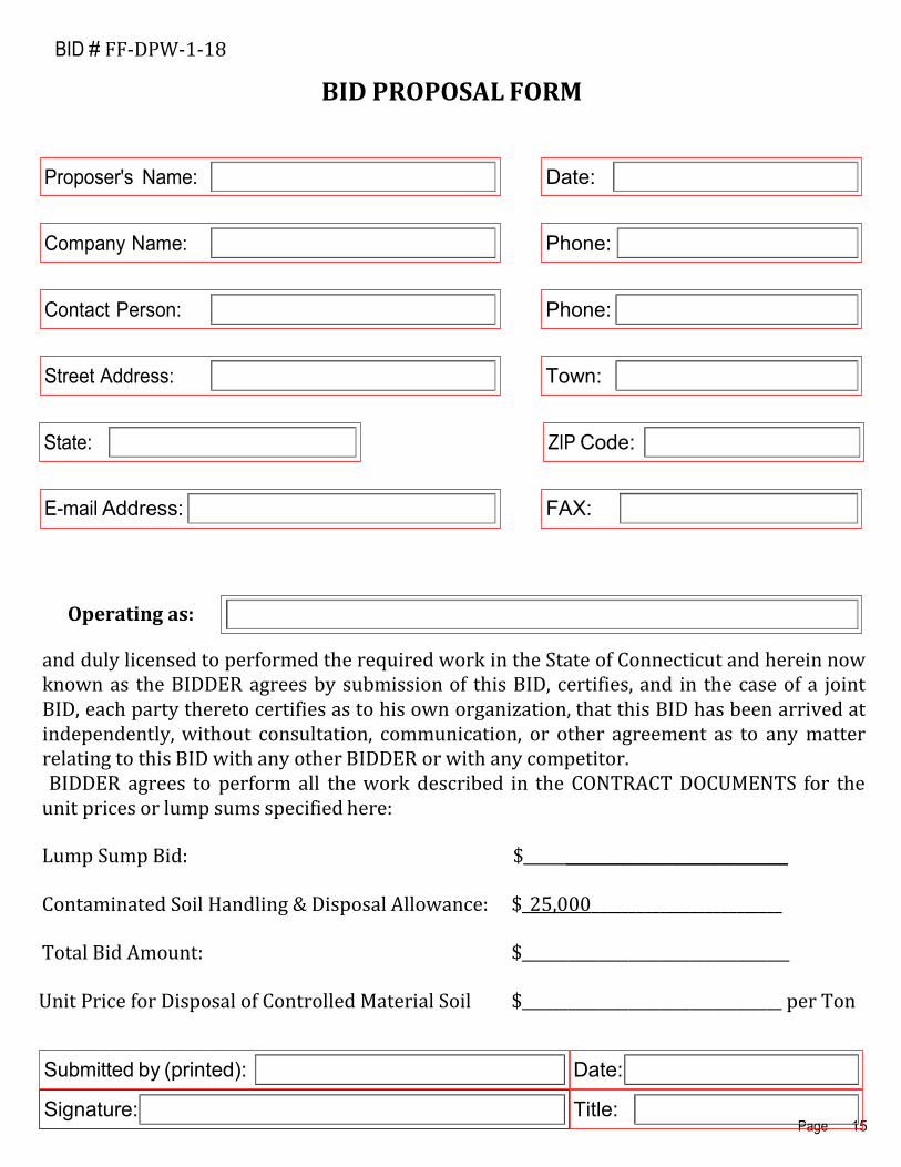
BID PROPOSAL FORM
Proposer's Name: Date:
Company Name: Phone:
Contact Person: Phone:
Street Address: Town:
State: ZIP Code:
E-mail Address:
Operating as:
FAX:
and duly licensed to performed the required work in the State of Connecticut and herein now known as the BIDDER agrees by submission of this BID, certifies, and in the case of a joint BID, each party thereto certifies as to his own organization, that this BID has been arrived at independently, without consultation, communication, or other agreement as to any matter relating to this BID with any other BIDDER or with any competitor. BIDDER agrees to perform all the work described in the CONTRACT DOCUMENTS for the
unit prices or lump sums specified here:
Lump Sump Bid: $ _____________________________ Contaminated Soil Handling & Disposal Allowance: $_25,000_________________________ Total Bid Amount: $___________________________________
Unit Price for Disposal of Controlled Material Soil $__________________________________ per Ton
Submitted by (printed): Date:
Signature: Title:

Page 16
BID # FF-DPW-1-18
SUBMITTING PROCEDURES
Bids may be considered INCOMPLETE if the following conditions are not met.
1. All forms must be filled out completely (Red highlighted boxes)
2. Bid Documents must be submitted as a complete set. Do not omit any pages
3. THREE (3) complete copies of your bid proposal must be submitted.
4. Bids are DUE in the Office of First Selectman prior to the advertised deadline. It is your responsibility to use what ever means necessary to assure that they are delivered on time.
5. Bids will be submitted in a sealed envelope and clearly marked with your name, the company name and the Bid #( FF-DPW-1-18)
It is suggested if you have any questions on the submittal process that you contact Mary Schettino, 860-669-9333 or [email protected] prior to the submittal deadline.

Clinton DPW Garage Fueling Station NOTICE TO CONTRACTOR Clinton, Connecticut
NOTICE TO CONTRACTOR
PART 1 - NOTICE TO CONTRACTOR – LIQUIDATED DAMAGES
1.1 The Town of Clinton advises the Contractor that time is of the essence in completing this work The Town of Clinton will suffer financial loss if the work is not delivered as specified contract time. The Town of Clinton will assess as liquidated damages for delay (but not as a penalty). Therefore; the Contractor shall pay The Town of Clinton, Two Hundred & Fifty dollars ($250.00) for each day that expires after the time specified in Part 2 notice to Contractor Contract Time below.
PART 2 - NOTICE TO CONTRACTOR - CONTRACT TIME
2.1 The date of completion for the total work shall be 120 Calendar Days from Notice to Proceed.

SECTION 01 10 00
SUMMARY
Clinton DPW Garage Fueling Station SUMMARY
Clinton, Connecticut 01 10 00 - 1
PART 1 - GENERAL
1.1 RELATED DOCUMENTS
A. Drawings and general provisions of the Contract, including General and Supplementary
Conditions and other Division 01 Specification Sections, apply to this Section.
1.2 SUMMARY
A. Section Includes:
1. Project information.
2. Work covered by Contract Documents.
3. Phased construction.
4. Work by Owner.
5. Work under separate contracts.
6. Future work.
7. Purchase contracts.
8. Owner-furnished products.
9. Contractor-furnished, Owner-installed products.
10. Access to site.
11. Coordination with occupants.
12. Work restrictions.
13. Specification and Drawing conventions.
14. Miscellaneous provisions.
B. Related Requirements:
1. Section 015000 "Temporary Facilities and Controls" for limitations and procedures
governing temporary use of Owner's facilities.
1.3 PROJECT INFORMATION
A. Project Identification: Public Works Diesel Tank Replacement and Fuel Farm Upgrades.
1. Project Location: Clinton Public Works Garage, 117 Nod Road, Clinton, CT 06413
B. Owner: Town of Clinton
1. Owner's Representative: Peter Neff – Director of Public Works
C. Architect: DTC Inc., 2321 Whitney Avenue, Suite 301, Hamden, CT 06518.

Clinton DPW Garage Fueling Station SUMMARY
Clinton, Connecticut 01 10 00 - 2
1.4 WORK COVERED BY CONTRACT DOCUMENTS
A. The Work of Project is defined by the Contract Documents and consists of the following:
1. This project includes the removal and disposal of an existing diesel UST, diesel fueling
island, and appurtenances, and construction of new 8,000 gal AST, fuel dispenser island,
fuel piping, electrical & telecom conduit and wiring, replacement fuel controller and
central monitoring system, reconfiguration of existing gasoline tank to include a new
submersible turbine pump, reconfiguration of existing gasoline fuel control and central
monitoring systems (to work with new equipment), and other Work indicated in the
Contract Documents.
B. Type of Contract:
1. Project will be constructed under a single prime contract.
1.5 PHASED CONSTRUCTION
A. The Work shall be conducted in three phases, with each phase substantially complete as
indicated.
1. Phase 1: Work in this phase includes removal and disposal of existing catch basin and
drainage pipe, and installation of new catch basin and drainage pipe. Work of this phase
will be performed by the Town of Clinton and will be substantially complete prior to
issuance of a Notice to Proceed for the remaining work on the project.
2. Phase 2: Work in this phase includes installation of a new Above Ground Diesel Storage
Tank including tank and all associated equipment, and concrete pad with bollards. Work
of this phase shall commence within 15 days after the Notice to Proceed and be
substantially complete within 60 days after the Notice to Proceed.
3. Phase 3: The remaining Work shall be substantially complete and ready for occupancy at
time of Substantial Completion for the Work.
B. Before commencing Work of each phase, submit an updated copy of Contractor's construction
schedule showing the sequence, commencement and completion dates for all phases of the
Work.
1.6 WORK BY OWNER
A. General: Cooperate fully with Owner so work may be carried out smoothly, without interfering
with or delaying work under this Contract or work by Owner. Coordinate the Work of this
Contract with work performed by Owner.
B. Preceding Work: Owner will perform the following construction operations at Project site.
Those operations are scheduled to be substantially complete before work under this Contract
begins.
1. Proposed Drainage Improvements.

Clinton DPW Garage Fueling Station SUMMARY
Clinton, Connecticut 01 10 00 - 3
1.7 ACCESS TO SITE
A. General: Contractor shall have limited use of Project site for construction operations as
indicated by requirements of this Section. The Contractor is cautioned that the proposed
construction activities take place at an active public works garage facility. Access in and
around the project site must be left open and available at all times during the duration of the
construction period. Contractor shall work closely with Clinton DPW Officials in reviewing
and evaluating any proposed construction operations that have any effect on site utilization and
circulation.
B. Driveways, Walkways and Entrances: Keep driveways, parking areas, garage buildings, loading
areas, and entrances serving premises clear and available to Owner, Owner's employees, and
emergency vehicles at all times. Do not use these areas for parking or for storage of materials.
a. Schedule deliveries to minimize use of driveways and entrances by construction
operations.
b. Schedule deliveries to minimize space and time requirements for storage of
materials and equipment on-site.
C. Use of Site: Limit use of Project site during Phase 2 to only areas necessary for completion of
the proposed AST installation. Do not disturb portions of Project site beyond areas in which the
Work is indicated. The Town intends to fully utilize the existing diesel and gasoline fueling
facilities during the Phase 2 AST installation.
D. Condition of Existing Building: Maintain portions of existing building affected by construction
operations in a weathertight condition throughout construction period. Repair damage caused by
construction operations.
E. Condition of Existing Grounds: Maintain portions of existing grounds, landscaping, and
hardscaping affected by construction operations throughout construction period. Repair damage
caused by construction operations.
1.8 COORDINATION WITH OCCUPANTS
A. Full Owner Occupancy: Owner will occupy site and existing building(s) during entire
construction period. Cooperate with Owner during construction operations to minimize conflicts
and facilitate Owner usage. Perform the Work so as not to interfere with Owner's day-to-day
operations. Maintain existing exits unless otherwise indicated.
1. Maintain access to existing walkways, corridors, and other adjacent occupied or used
facilities. Do not close or obstruct walkways, corridors, or other occupied or used
facilities without written permission from Owner and approval of authorities having
jurisdiction.
2. Notify Owner not less than 72 hours in advance of activities that will affect Owner's
operations.
1.9 WORK RESTRICTIONS
A. Work Restrictions, General: Comply with restrictions on construction operations.

Clinton DPW Garage Fueling Station SUMMARY
Clinton, Connecticut 01 10 00 - 4
1. Comply with limitations on use of public streets and with other requirements of
authorities having jurisdiction.
B. On-Site Work Hours: Limit work in the existing building to normal business working hours of
7:30 a.m. to 5:00 p.m., Monday through Friday, unless otherwise indicated.
1. Weekend Hours: May be permitted after review of Contractors advanced written request
2. Early Morning Hours: Not allowed.
3. Hours for Utility Shutdowns: Not allowed.
C. Noise, Vibration, and Odors: Coordinate operations that may result in high levels of noise and
vibration, odors, or other disruption to Owner occupancy with Owner.
1. Notify Architect and Owner not less than two days in advance of proposed disruptive
operations.
2. Obtain Architect's written permission before proceeding with disruptive operations.
D. Restricted Substances: Use of tobacco products and other controlled substances on Project site
is not permitted.
E. Employee Identification: Provide identification tags for Contractor personnel working on
Project site. Require personnel to use identification tags at all times.
F. Employee Screening: Comply with Owner's requirements for drug and background screening of
Contractor personnel working on Project site.
1. Maintain list of approved screened personnel with Owner's representative.
1.10 SPECIFICATION AND DRAWING CONVENTIONS
A. Specification Content: The Specifications use certain conventions for the style of language and
the intended meaning of certain terms, words, and phrases when used in particular situations.
These conventions are as follows:
1. Imperative mood and streamlined language are generally used in the Specifications. The
words "shall," "shall be," or "shall comply with," depending on the context, are implied
where a colon (:) is used within a sentence or phrase.
2. Specification requirements are to be performed by Contractor unless specifically stated
otherwise.
B. Division 01 General Requirements: Requirements of Sections in Division 01 apply to the Work
of all Sections in the Specifications.
C. Drawing Coordination: Requirements for materials and products identified on Drawings are
described in detail in the Specifications. One or more of the following are used on Drawings to
identify materials and products:
1. Terminology: Materials and products are identified by the typical generic terms used in
the individual Specifications Sections.

Clinton DPW Garage Fueling Station SUMMARY
Clinton, Connecticut 01 10 00 - 5
2. Keynoting: Materials and products are identified by reference keynotes referencing
Specification Section numbers found in this Project Manual.
PART 2 - PRODUCTS (Not Used)
PART 3 - EXECUTION (Not Used)
END OF SECTION 011000

SECTION 01 11 10
ENVIRONMENTAL HEALTH & SAFETY
Clinton DPW Garage Fueling Station ENVIRONMENTAL HEALTH & SAFETY
Clinton, Connecticut 01 11 10 - 1
PART 1 - GENERAL
1.1 RELATED DOCUMENTS
A. Drawings and General Provisions of the Contract, including General and Supplementary
Conditions and Division 1 Specifications Sections, apply to this Section.
1.2 SUMMARY
A. Section Includes:
1. Establishing protocols and providing procedures to protect worker’s health and safety
specifically when workers are handling, or otherwise may be exposed to, contaminants
present in Underground Storage Tanks.
2. Preparing a site-specific Health and Safety Plan (HASP).
3. Training requirements.
4. THE ESTABLISHMENT OF PROTOCOLS AND PROCEDURES TO ADDRESS
POTENTIAL AND/OR ACTUAL RISK OF EXPOSURE TO SITE-SPECIFIC HAZARDS
POSED TO CONTRACTOR’S EMPLOYEES AND SUBCONTRACTORS IS SOLELY
THE RESPONSIBILITY OF THE CONTRACTOR.
B. Related Requirements:
1. Section 017620 – Excavation and Handling of Controlled Materials
2. Section 026500 – Underground Storage Tank Cleaning, Removal, and Disposal
3. Section 312100 – Disposal of Controlled Materials
1.3 DEFINITIONS
A. Certified Hazardous Material Manager (CHMM): A person certified by the Institute of
Hazardous Materials Management.
B. Certified Industrial Hygienist (CIH): A person certified by the American Board of Industrial
Hygiene.
C. Certified Safety Professional (CSP): A person certified by the Board of Certified Safety
Professionals.
D. Chemical Protective Clothing (CPC): Clothing worn to shield or isolate individuals from the
chemical, physical, and biological hazards that may be encountered during construction
operations involving contaminated building materials and Controlled Material.
E. Contractor-designated Health and Safety Manager (HSM): Qualified person responsible for the
development of the Contractor’s HASP, who shall be a CIH, CSP, or CHMM. The HSM shall
have review and approval authority over the HASP, and the HASP shall bear the signature of said
HSM indicating that the HASP meets the minimum requirements of 29 CFR 1910.120, 29 CFR
1910.1001, 29 CFR 1910.1101, and 29 CFR 1926.65.

Clinton DPW Garage Fueling Station ENVIRONMENTAL HEALTH & SAFETY
Clinton, Connecticut 01 11 10 - 2
F. Contractor-designated On-site Health and Safety Officer (HSO): Certified person having full
authority to carry out and ensure compliance with the Contractor’s HASP. In accordance with 29
CFR 1926, one who is trained and capable of identifying existing or potential hazards within the
Project limits, or working conditions which are or may present a hazard, and who has authority to
take prompt corrective action to eliminate such hazards. NOTE: The Contractor shall designate
an HSO who shall be on-site full-time during all work associated with UST removal, petroleum
impacted soil excavation activities (if encountered). If the Contractor’s HSO is not on site at any
time whatsoever, all work shall be stopped. The Contractor’s HSO shall not be removed from the
project without the written approval of the Owner.
G. HASP: Contractor’s Site-specific Health and Safety Plan. The HASP shall establish health and
safety protocols that address the relative risk of exposure to regulated substances in accordance
with 29 CFR 1910.120, 29 CFR 1910.1001, 29 CFR 1910.1101, and 29 CFR 1926.65. Such
protocols shall only address those concerns directly related to site conditions.
H. Personal Protective Equipment (PPE): Equipment worn to minimize exposure to a variety of
hazards. Examples of PPE include such items as gloves, foot and eye protection, protective
hearing devices (earplugs, muffs), hard hats, respirators, and full body suits.
1.4 REGULATORY REQUIREMENTS
A. The following statutes, laws, regulations, and standards are cited for the information and guidance
of the Contractor. The list below is not all-inclusive. The Contractor shall be responsible for a
thorough knowledge and full implementation of all requirements for removal, management,
transportation, and disposal of the materials managed under this Section.
1. 29 CFR 1910 “Safety and Health Regulations for General Industry”.
2. 29 CFR 1910.120 “Hazardous Waste Site Operations and Emergency Response”
(HAZWOPER), where appropriate.
3. 29 CFR 1910.1200 “Hazard Communication (HAZCOM)”.
4. 29 CFR 1926 “Safety and Health Regulations for Construction”.
5. Publications, Practices for Respiratory Protection, z88.2-1992 – American National Standards
Institute (ANSI).
6. All other applicable Local, State and Federal regulations applicable to the work.
1.5 SUBMITTALS FOR REVIEW
A. At least four (4) weeks prior to starting any construction activities, Contractor shall submit two
(2) copies of their Corporate Health & Safety Plan (CHASP) to the Owner.
B. At least three (3) weeks before the start of the UST removal activities, the Contractor shall submit
three (3) copies of their Site-specific HASP for this project to the Owner for review. If the HASP
does not bear the signature and license number of the HSM, it will be rejected and not reviewed.
The Owner shall review the HASP for conformance with the specifications within two (2) weeks
after submittal and shall provide written comments to the Contractor as to deficiencies in and/or
exceptions to the HASP, if any, to assure consistency with the specifications, applicable
standards, policies and practices, and appropriateness given potential or known site conditions.
Items identified in the HASP which do not conform to the specifications will be brought to the
Clinton DPW Garage Fueling Station ENVIRONMENTAL HEALTH & SAFETY
Clinton, Connecticut 01 11 10 - 3
attention of the Contractor, and the Contractor shall revise the HASP to correct the deficiencies
and resubmit it to the Owner for determination of compliance with this Section. The Contractor
shall not be allowed to commence work activities involving UST removal activities or where site
conditions exist that may pose a risk to worker health and safety and/or the environment, until the
HASP has been reviewed and accepted by the Owner. No claim for delay in the progress of work
will be considered for the Contractor’s failure to submit a Site-specific HASP that conforms to
the requirements of the Contract.
C. The HASP shall include copies of the Contractor-designated HSO’s and HSM’s training
certificates as well as a demonstration of the required experience, as indicated in Part 2(2.1)(C)(3)
of this Section.
PART 2 - PRODUCTS
2.1 HASP
A. General Requirements: The Contractor shall prepare a HASP covering all Project site work
regulated by 29 CFR 1910.120, 29 CFR 1910.1001, 29 CFR 1910.1025, 29 CFR 1910.1101, and
29 CFR 1926.62, 29 CFR 1926.65(b) to be performed by the Contractor and all subcontractors
under this Contract. The HASP shall establish in detail, the protocols necessary for the
recognition, evaluation, and control of all hazards associated with each task performed under this
Contract. The HASP shall address site-specific safety and health hazards of each phase of site
operation and include the requirements and procedures for employee protection. The level of
detail provided in the HASP shall be tailored to the type of work, complexity of operations to be
performed, and hazards anticipated. Details about some activities may not be available when the
initial HASP is prepared and submitted. Therefore, the HASP shall address, in as much detail as
possible, all anticipated tasks, their related hazards and anticipated control measures.
B. The HASP shall interface with the Contractor’s Corporate Safety and Health Program. All topics
regulated by 29 CFR 1910.120(b)(4), and those listed below, shall be addressed in the HASP.
Where the use of a specific topic is not applicable to the Project, the HASP shall include a
statement to justify its omission or reduced level of detail and establish that adequate
consideration was given the topic.
C. Elements: The following elements shall be included in the site-specific HASP.
1. Site Description and Contamination Characterization: The Contractor shall provide a site
description and contaminant characterization in the HASP that meets the applicable
requirements of 29 CFR 1910.120, 29 CFR 1910.1001, 29 CFR 1910.1101, and 1926.65.
2. Safety and Health Risk Analysis / Activity Hazard Analysis: The HASP shall address the
safety and health hazards on this site for every operation to be performed during UST
removal activities. The Contractor shall review existing records and data to identify potential
chemical and physical hazards associated with the site and shall evaluate their impact on field
operations. Sources, concentrations (if known), potential exposure pathways, and other
factors as noted in CFR 1910.120 and paragraph (c)(7) of 29 CFR 1926.65, employed to
assess risk shall be described. The Contractor shall develop and justify “Action Levels” for

Clinton DPW Garage Fueling Station ENVIRONMENTAL HEALTH & SAFETY
Clinton, Connecticut 01 11 10 - 4
implementation of engineering controls and PPE upgrades and downgrades for controlling
worker exposure to the identified hazards. If there is no permissible exposure limit (PEL) or
published exposure level for an identified hazard, available information from other published
studies may be used as guidance. Any modification of a regulatory PEL must be fully
documented.
The HASP shall include a comprehensive section that discusses the tasks and objectives of
the site operations and logistics and resources required to complete each task associated with
UST removal activities. The hazards associated with each task shall be identified. Hazard
prevention techniques, procedures, and/or equipment shall be identified to mitigate each of
the hazards identified.
3. Staff Organization, Qualifications and Responsibilities: The HASP shall include a list of
personnel expected to be engaged in site activities and certify that said personnel have
completed the educational requirements stipulated in 29 CFR 1910.120, 29 CFR 1910.1001,
29 CFR 1910.1025, 29 CFR 1910.1101, 29 CFR 1926.1101, 29 CFR 1926.62, and 29 CFR
1926.65, are currently monitored under a medical surveillance program in compliance with
those regulations, and that they are fit for work under “level C” PPE conditions.
For some operations, “Level B” PPE may be necessary. The HASP shall include a list of
personnel that may be required to use Level B PPE.
The Contractor shall assign responsibilities for safety activities and procedures. An outline or
flow chart of the safety chain of command shall be provided in the HASP. Qualifications,
including education, experience, certifications, and training in safety and health for all
personnel engaged in safety and health functions shall be documented in the HASP. Specific
duties of each on-site team member shall be identified.
The HASP shall also include the name and qualifications of the individual proposed to serve
as HSO. The HSO shall have full authority to carry out and ensure compliance with the
HASP. The Contractor shall provide a competent HSO on site who is capable of identifying
existing and potential hazards in the surroundings or working conditions which are
unsanitary, hazardous, or dangerous to employees and who has authorization to take prompt
corrective measures to eliminate or control them. The Contractor’s HSO shall be on site full-
time during all work associated with UST closure activities. If the Contractor’s HSO is not
on site at any time whatsoever, all work shall be stopped.
The qualifications of the HSO SHALL include completion of OSHA 40-hour HAZWOPER
training (including current 8-hour refresher training); 8-hour HAZWOPER supervisory
training; a minimum of one (1) year of working experience with the regulated compounds
that have been documented to exist within the Project limits; a working knowledge of Federal
and State safety regulations; specialized training in personal and respiratory protective
equipment program implementation; the proper use of air monitoring instruments, air
sampling methods, and procedures; and certification training in first aid and CPR by a
recognized, approved organization such as the American Red Cross.
The primary duties of the HSO shall be those associated with worker health and safety. The
Contractor’s HSO responsibilities shall be detailed in the written HASP and shall include, but
not be limited to the following:
(A) Directing and implementing the HASP.

Clinton DPW Garage Fueling Station ENVIRONMENTAL HEALTH & SAFETY
Clinton, Connecticut 01 11 10 - 5
(B) Ensuring that all Project personnel have been adequately trained in the recognition and
avoidance of unsafe conditions and the regulations applicable to the work environment to
control or eliminate any hazards or other exposure to illness or injury (29 CFR 1926.21).
All personnel shall be adequately trained in procedures outlined in the Contractor’s
written HASP.
(C) Authorizing Stop Work Orders, which shall be executed upon the determination of an
imminent health and safety concern.
(D) Contacting the Contractor’s HSM and the Owner immediately upon the issuance of a
Stop Work order when the HSO has made the determination of an imminent health and
safety concern.
(E) Authorizing work to resume, upon approval from the Contractor’s HSM and the Owner.
(F) Directing activities, as defined in the Contractor’s written HASP, during emergency
situations; and
(G) Providing personal monitoring where applicable and as identified in the HASP.
4. Employee Training: The Contractor shall develop a training program to inform employees,
supplier’s representatives, and visitors on behalf of the Contractor of the special hazards and
procedures (including PPE, its uses and inspections) to control these hazards during field
operations. This program shall be consistent with the applicable requirements of 29 CFR
1910.120, 29 CFR 1910.1001, 29 CFR 1910.1025, 29 CFR 1926.1101, 29 CFR 1926.62, and
29 CFR 1926.65.
5. Personal Protective Equipment: The plan shall include the requirements and procedures for
employee protection and shall include a detailed section on respiratory protection. The
Contractor shall describe in detail and provide appropriate PPE to ensure that workers are not
exposed to levels greater than the Action Level for identified hazards for each operation
stated for each work zone. The level of protection shall be specific for each operation and
shall be in compliance with all applicable requirements of 29 CFR 1910 and 29 CFR 1926.
The Contractor shall provide, maintain, and properly dispose of all PPE.
6. Medical Surveillance Program: All on-site Contractor personnel engaged in 29 CFR
1910.120, 29 CFR 1910.1001, 29 CFR 1910.1025, 29 CFR 1926.1101, 29 CFR 1926.62, and
1926.65 operations shall have medical examinations meeting the requirements of 29 CFR
1910.120(f) and/or other applicable OSHA regulatory requirements for compounds
associated with diesel fuel, etc. prior to commencement of work.
The HASP shall include certification of medical evaluation and clearance by the physician for
each employee engaged in 29 CFR 1910.120, 29 CFR 1910.1001, 29 CFR 1910.1025, 29
CFR 1926.1101, 29 CFR 1926.62, 1926.65 operations (as applicable) at the site.
7. Site Layout and Control: The HASP shall include a map, work zone delineation (support,
contamination, reduction, exclusion zones; soil “Work Areas”; waste storage areas; &
decontamination stations), on/off-site communications, site access controls, and security
(physical and procedural).
8. Communications: Written procedures for routine and emergency communications shall be
included in the Contractor’s HASP.
Clinton DPW Garage Fueling Station ENVIRONMENTAL HEALTH & SAFETY
Clinton, Connecticut 01 11 10 - 6
9. Personal Hygiene, Personal and Equipment Decontamination: Decontamination facilities and
procedures for PPE, sampling equipment, and heavy equipment shall be discussed in detail in
the HASP.
10. Emergency Equipment and First Aid Requirements: The Contractor shall provide appropriate
emergency first aid kits and equipment. The Contractor shall provide at least one person that
has certified first aid / CPR training on site at all times during site UST closure operations.
11. Emergency Response Plan (ERP) and Spill Containment Program: The Contractor shall
establish procedures in order to take emergency action in the event of immediate hazards (i.e.,
a chemical agent leak or spill, fire, or personal injury). Personnel and facilities supplying
support in emergency procedures will be identified. The emergency equipment to be present
on site and the emergency response procedures, as required by 29 CFR 1910.120, paragraph
(1)(1)(ii), shall be specified in the ERP. The ERP shall be included as part of the HASP. The
ERP shall include written directions to the closest hospital as well as a map showing the route
to the hospital.
12. Logs, Reports, and Record Keeping: The Contractor shall maintain safety inspections, logs,
weekly reports, accident/incident reports, medical certifications, training logs, monitoring
results, etc. All exposure and medical monitoring records are to be maintained according to
29 CFR 1910 and 29 CFR 1926. The format of these logs and reports shall be developed by
the Contractor to include training logs, daily logs, weekly reports, safety meetings, medical
surveillance records, and a phase-out report. These logs, records, and reports shall be
maintained by the Contractor and be made available to the Owner.
The Contractor shall immediately notify the Owner of any accident or incident. Within two
(2) working days of any reportable accident, the Contractor shall complete and submit to the
Owner an accident report.
13. Confined space entry procedures: Confined space entry procedures, both permit required and
non-permit required, shall be discussed in detail.
14. “Tailgate health & safety briefings”: The HASP shall provide for daily tailgate health and
safety briefings to be held at the start of each workday to ensure that employees are apprised
of the HASP, the specific tasks for that particular day, and the appropriate health and safety
procedures.
15. Inspections/audits: The HSM or HSO shall conduct inspections or audits to determine the
effectiveness of the HASP. The Contractor shall correct any deficiencies in the effectiveness
of the HASP.
PART 3 - EXECUTION
3.1 IMPLEMENTATION
A. The Contractor shall implement and maintain the HASP throughout the performance of work
associated with the UST closure activities. In areas identified as having a potential risk to worker
health and safety, and in any other areas deemed appropriate by the HSO, the Contractor shall be
prepared to immediately implement the appropriate health and safety measures, including but not
limited to the use of PPE, and engineering and administrative controls.

Clinton DPW Garage Fueling Station ENVIRONMENTAL HEALTH & SAFETY
Clinton, Connecticut 01 11 10 - 7
B. If the Owner observes deficiencies in the Contractor’s operations with respect to the HASP, they
shall be assembled in a written field directive and given to the Contractor. The Contractor shall
immediately correct the deficiencies and respond, in writing, as to how each was corrected.
Failure to bring the work area(s) and implementation procedures into compliance will result in a
Stop Work Order and a written directive to discuss an appropriate resolution(s) to the matter.
When the Contractor demonstrates compliance, the Owner shall remove the Stop Work Order. If
a Stop Work Order has been issued for cause, no delay claims on the part of the Contractor will
be honored.
C. Disposable CPC/PPE, i.e. disposable coveralls, gloves, etc.: Handling, storage, and disposal of
CPC/PPE used during UST closure activities shall be handled in accordance with the provisions
of the applicable section governing that work.
3.2 REVISIONS
A. The HASP shall be maintained on site by the Contractor and shall be kept current with
construction activities and site conditions under this Contract. The HASP shall be recognized as
a flexible document which shall be subject to revisions and amendments, as required, in response
to actual site conditions, changes in work methods and/or alterations in the relative risk present.
All changes and modifications shall be signed by the Contractor’s HSM and shall require the
review and acceptance by the Owner prior to the implementation of such changes.
B. Should any unforeseen hazard become evident during the performance of the work, the HSO shall
bring such hazard to the attention of the Contractor and the Owner as soon as possible. In the
interim, the Contractor shall take action, including stopping work and/or upgrading PPE as
necessary to re-establish and maintain safe working conditions and to safeguard on-site
personnel, visitors, the public, and the environment. The HASP shall then be revised/amended to
reflect the changed condition.
C. The Contractor shall demonstrate to the Owner monthly that the HASP has been kept current and
is being implemented.
3.3 FAILURE TO COMPLY
A. Failure to fully comply with this Section, the HASP, and all applicable OSHA regulations will
result in immediate cessation of activities until compliance with the HASP and applicable
regulations is achieved.
END OF SECTION 011110

SECTION 01 21 00
ALLOWANCES
Clinton DPW Garage Fueling Station Clinton, Connecticut
ALLOWANCES 01 21 00 - 1
PART 1 - GENERAL
1.1 RELATED DOCUMENTS
A. Drawings and general provisions of the Contract, including General and Supplementary Conditions and other Division 01 Specification Sections, apply to this Section.
1.2 SUMMARY
A. Section includes administrative and procedural requirements governing allowances.
B. Types of allowances include the following: 1. Unit-cost allowances.
C. Related Requirements:
1. Section 012200 "Unit Prices" for procedures for using unit prices, including adjustment of quantity allowances when applicable.
2. Section 014000 "Quality Requirements" for procedures governing the use of allowances for field testing by an independent testing agency.
1.3 DEFINITIONS
A. Allowance is a quantity of work or dollar amount established in lieu of additional requirements, used to provide a payment means for pre-defined construction items that cannot be accurately quantified prior to the time of bid.
1.4 INFORMATIONAL SUBMITTALS
A. Coordinate and process submittals for allowance items in same manner as for other portions of the Work.
1.5 ALLOWANCES
A. Allowance shall include cost to Contractor of specific products and materials ordered by Owner or selected by Architect under allowance and shall include delivery to Project site.

Clinton DPW Garage Fueling Station Clinton, Connecticut
ALLOWANCES 01 21 00 - 2
PART 2 - PRODUCTS (Not Used)
PART 3 - EXECUTION
3.1 EXAMINATION
A. Examine products covered by an allowance promptly on delivery for damage or defects. Return damaged or defective products to manufacturer for replacement.
3.2 PREPARATION
A. Coordinate materials and their installation for each allowance with related materials and installations to ensure that each allowance item is completely integrated and interfaced with related work.
3.3 SCHEDULE OF ALLOWANCES
A. Allowance No. 1: The Contractor shall include the sum of $25,000 in his bid to be billed against for disposal of Controlled Material Soil as detailed in Section 01 22 00 Unit Prices, and Section 31 21 00 Disposal of Controlled Material Soil. Controlled Material Soil disposal will be paid for under this Allowance at the negotiated unit price multiplied by the actual quantity of Controlled Material Soil disposed of.
1. This allowance includes material cost, receiving, handling, and installation, and Contractor overhead and profit.
END OF SECTION 012100

SECTION 01 22 00
UNIT PRICES
Clinton DPW Garage Fueling Station UNIT PRICES
Clinton, Connecticut 01 22 00 - 1
PART 1 - GENERAL
1.1 RELATED DOCUMENTS
A. Drawings and general provisions of the Contract, including General and Supplementary
Conditions and other Division 01 Specification Sections, apply to this Section.
1.2 SUMMARY
A. Section includes administrative and procedural requirements for unit prices.
B. Related Requirements:
1. Section 012100 "Allowances" for procedures for using unit prices to adjust quantity
allowances.
2. Section 012600 "Contract Modification Procedures" for procedures for submitting and
handling Change Orders.
3. Section 014000 "Quality Requirements" for field testing by an independent testing
agency.
1.3 DEFINITIONS
A. Unit price is an amount incorporated into the Agreement, applicable during the duration of the
Work as a price per unit of measurement for materials, equipment, or services, or a portion of
the Work, added to or deducted from the Contract Sum by appropriate modification, if the scope
of Work or estimated quantities of Work required by the Contract Documents are increased or
decreased.
1.4 PROCEDURES
A. Unit prices include all necessary material, plus cost for delivery, installation, insurance,
overhead, and profit.
B. Measurement and Payment: See individual Specification Sections for work that requires
establishment of unit prices. Methods of measurement and payment for unit prices are specified
in those Sections.
C. Owner reserves the right to reject Contractor's measurement of work-in-place that involves use
of established unit prices and to have this work measured, at Owner's expense, by an
independent surveyor acceptable to Contractor.
D. List of Unit Prices: A schedule of unit prices is included in Part 3. Specification Sections
referenced in the schedule contain requirements for materials described under each unit price.

Copyright 2015 AIA MasterSpec Premium 09/15
Clinton DPW Garage Fueling Station UNIT PRICES
Clinton, Connecticut 01 22 00 - 2
PART 2 - PRODUCTS (Not Used)
PART 3 - EXECUTION
3.1 SCHEDULE OF UNIT PRICES
A. Unit Price No. 1: Disposal of Controlled Material Soil.
1. Description: Controlled material soil handling and disposal off-site and replacement with
satisfactory granular fill from off-site, as required, according to Section 312000 "Earth
Moving."
2. Unit of Measurement: Tons of soil excavated, based on weight bills issued by the
licensed disposal facility.
3. Quantity Allowance: Coordinate unit price with allowance adjustment requirements in
Section 012100 "Allowances."
END OF SECTION 012200

SECTION 01 25 00
SUBSTITUTION PROCEDURES
Clinton DPW Garage Fueling Station SUBSTITUTION PROCEDURES
Clinton, Connecticut 01 25 00 - 1
PART 1 - GENERAL
1.1 RELATED DOCUMENTS
A. Drawings and general provisions of the Contract, including General and Supplementary
Conditions and other Division 01 Specification Sections, apply to this Section.
1.2 SUMMARY
A. Section includes administrative and procedural requirements for substitutions.
1.3 DEFINITIONS
A. Substitutions: Changes in products, materials, equipment, and methods of construction from
those required by the Contract Documents and proposed by Contractor.
1. Substitutions for Cause: Changes proposed by Contractor that are required due to
changed Project conditions, such as unavailability of product, regulatory changes, or
unavailability of required warranty terms.
2. Substitutions for Convenience: Changes proposed by Contractor or Owner that are not
required in order to meet other Project requirements but may offer advantage to
Contractor or Owner.
1.4 ACTION SUBMITTALS
A. Substitution Requests: Submit three copies of each request for consideration. Identify product or
fabrication or installation method to be replaced. Include Specification Section number and title
and Drawing numbers and titles.
1. Substitution Request Form: Use facsimile of form provided in Project Manual.
2. Documentation: Show compliance with requirements for substitutions and the following,
as applicable:
a. Statement indicating why specified product or fabrication or installation method
cannot be provided, if applicable.
b. Coordination of information, including a list of changes or revisions needed to
other parts of the Work and to construction performed by Owner and separate
contractors that will be necessary to accommodate proposed substitution.
c. Detailed comparison of significant qualities of proposed substitutions with those of
the Work specified. Include annotated copy of applicable Specification Section.
Significant qualities may include attributes, such as performance, weight, size,
durability, visual effect, sustainable design characteristics, warranties, and specific

Clinton DPW Garage Fueling Station SUBSTITUTION PROCEDURES
Clinton, Connecticut 01 25 00 - 2
features and requirements indicated. Indicate deviations, if any, from the Work
specified.
d. Product Data, including drawings and descriptions of products and fabrication and
installation procedures.
e. Samples, where applicable or requested.
f. Certificates and qualification data, where applicable or requested.
g. List of similar installations for completed projects, with project names and
addresses as well as names and addresses of architects and owners.
h. Material test reports from a qualified testing agency, indicating and interpreting
test results for compliance with requirements indicated.
i. Research reports evidencing compliance with building code in effect for Project.
j. Detailed comparison of Contractor's construction schedule using proposed
substitutions with products specified for the Work, including effect on the overall
Contract Time. If specified product or method of construction cannot be provided
within the Contract Time, include letter from manufacturer, on manufacturer's
letterhead, stating date of receipt of purchase order, lack of availability, or delays
in delivery.
k. Cost information, including a proposal of change, if any, in the Contract Sum.
l. Contractor's certification that proposed substitution complies with requirements in
the Contract Documents, except as indicated in substitution request, is compatible
with related materials and is appropriate for applications indicated.
m. Contractor's waiver of rights to additional payment or time that may subsequently
become necessary because of failure of proposed substitution to produce indicated
results.
3. Architect's Action: If necessary, Architect will request additional information or
documentation for evaluation within seven days of receipt of a request for substitution.
Architect will notify Contractor of acceptance or rejection of proposed substitution within
15 days of receipt of request, or seven days of receipt of additional information or
documentation, whichever is later.
a. Forms of Acceptance: Change Order, Construction Change Directive, or
Architect's Supplemental Instructions for minor changes in the Work.
b. Use product specified if Architect does not issue a decision on use of a proposed
substitution within time allocated.
1.5 QUALITY ASSURANCE
A. Compatibility of Substitutions: Investigate and document compatibility of proposed substitution
with related products and materials. Engage a qualified testing agency to perform compatibility
tests recommended by manufacturers.
1.6 PROCEDURES
A. Coordination: Revise or adjust affected work as necessary to integrate work of the approved
substitutions.

Clinton DPW Garage Fueling Station SUBSTITUTION PROCEDURES
Clinton, Connecticut 01 25 00 - 3
1.7 SUBSTITUTIONS
A. Substitutions for Cause: Submit requests for substitution immediately on discovery of need for
change, but not later than 15 days prior to time required for preparation and review of related
submittals.
1. Conditions: Architect will consider Contractor's request for substitution when the
following conditions are satisfied. If the following conditions are not satisfied, Architect
will return requests without action, except to record noncompliance with these
requirements:
a. Requested substitution is consistent with the Contract Documents and will produce
indicated results.
b. Substitution request is fully documented and properly submitted.
c. Requested substitution will not adversely affect Contractor's construction schedule.
d. Requested substitution has received necessary approvals of authorities having
jurisdiction.
e. Requested substitution is compatible with other portions of the Work.
f. Requested substitution has been coordinated with other portions of the Work.
g. Requested substitution provides specified warranty.
h. If requested substitution involves more than one contractor, requested substitution
has been coordinated with other portions of the Work, is uniform and consistent, is
compatible with other products, and is acceptable to all contractors involved.
B. Substitutions for Convenience: Architect will consider requests for substitution if received
within 15 days after the Notice to Proceed. Requests received after that time may be considered
or rejected at discretion of Architect.
1. Conditions: Architect will consider Contractor's request for substitution when the
following conditions are satisfied. If the following conditions are not satisfied, Architect
will return requests without action, except to record noncompliance with these
requirements:
a. Requested substitution offers Owner a substantial advantage in cost, time, energy
conservation, or other considerations, after deducting additional responsibilities
Owner must assume. Owner's additional responsibilities may include
compensation to Architect for redesign and evaluation services, increased cost of
other construction by Owner, and similar considerations.
b. Requested substitution does not require extensive revisions to the Contract
Documents.
c. Requested substitution is consistent with the Contract Documents and will produce
indicated results.
d. Substitution request is fully documented and properly submitted.
e. Requested substitution will not adversely affect Contractor's construction schedule.
f. Requested substitution has received necessary approvals of authorities having
jurisdiction.
g. Requested substitution is compatible with other portions of the Work.
h. Requested substitution has been coordinated with other portions of the Work.
i. Requested substitution provides specified warranty.

Clinton DPW Garage Fueling Station SUBSTITUTION PROCEDURES
Clinton, Connecticut 01 25 00 - 4
j. If requested substitution involves more than one contractor, requested substitution
has been coordinated with other portions of the Work, is uniform and consistent, is
compatible with other products, and is acceptable to all contractors involved.
PART 2 - PRODUCTS (Not Used)
PART 3 - EXECUTION (Not Used)
END OF SECTION 012500

SECTION 01 26 00
CONTRACT MODIFICATION PROCEDURES
Clinton DPW Garage Fueling Station
Clinton, Connecticut
CONTRACT MODIFICATION PROCEDURES
01 26 00 - 1
PART 1 - GENERAL
1.1 RELATED DOCUMENTS
A. Drawings and general provisions of the Contract, including General and Supplementary
Conditions and other Division 01 Specification Sections, apply to this Section.
1.2 SUMMARY
A. Section includes administrative and procedural requirements for handling and processing
Contract modifications.
B. Related Requirements:
1. Section 012500 "Substitution Procedures" for administrative procedures for handling
requests for substitutions made after the Contract award.
1.3 MINOR CHANGES IN THE WORK
A. Architect will issue supplemental instructions authorizing minor changes in the Work, not
involving adjustment to the Contract Sum or the Contract Time, on AIA Document G710.
1.4 PROPOSAL REQUESTS
A. Owner-Initiated Proposal Requests: Architect will issue a detailed description of proposed
changes in the Work that may require adjustment to the Contract Sum or the Contract Time. If
necessary, the description will include supplemental or revised Drawings and Specifications.
1. Work Change Proposal Requests issued by Architect are not instructions either to stop
work in progress or to execute the proposed change.
2. Within time specified in Proposal Request after receipt of Proposal Request, submit a
quotation estimating cost adjustments to the Contract Sum and the Contract Time
necessary to execute the change.
a. Include a list of quantities of products required or eliminated and unit costs, with
total amount of purchases and credits to be made. If requested, furnish survey data
to substantiate quantities.
b. Indicate applicable taxes, delivery charges, equipment rental, and amounts of trade
discounts.
c. Include costs of labor and supervision directly attributable to the change.
d. Include an updated Contractor's construction schedule that indicates the effect of
the change, including, but not limited to, changes in activity duration, start and

Clinton DPW Garage Fueling Station
Clinton, Connecticut
CONTRACT MODIFICATION PROCEDURES
01 26 00 - 2
finish times, and activity relationship. Use available total float before requesting an
extension of the Contract Time.
e. Quotation Form: Use forms acceptable to Architect.
B. Contractor-Initiated Proposals: If latent or changed conditions require modifications to the
Contract, Contractor may initiate a claim by submitting a request for a change to Architect.
1. Include a statement outlining reasons for the change and the effect of the change on the
Work. Provide a complete description of the proposed change. Indicate the effect of the
proposed change on the Contract Sum and the Contract Time.
2. Include a list of quantities of products required or eliminated and unit costs, with total
amount of purchases and credits to be made. If requested, furnish survey data to
substantiate quantities.
3. Indicate applicable taxes, delivery charges, equipment rental, and amounts of trade
discounts.
4. Include costs of labor and supervision directly attributable to the change.
5. Include an updated Contractor's construction schedule that indicates the effect of the
change, including, but not limited to, changes in activity duration, start and finish times,
and activity relationship. Use available total float before requesting an extension of the
Contract Time.
6. Comply with requirements in Section 012500 "Substitution Procedures" if the proposed
change requires substitution of one product or system for product or system specified.
7. Proposal Request Form: Use form acceptable to Architect.
1.5 CHANGE ORDER PROCEDURES
A. On Owner's approval of a Work Change Proposal Request, Architect will issue a Change Order
for signatures of Owner and Contractor on AIA Document G701
1.6 CONSTRUCTION CHANGE DIRECTIVE
A. Construction Change Directive: Architect may issue a Construction Change Directive on
AIA Document G714. Construction Change Directive instructs Contractor to proceed with a
change in the Work, for subsequent inclusion in a Change Order.
1. Construction Change Directive contains a complete description of change in the Work. It
also designates method to be followed to determine change in the Contract Sum or the
Contract Time.
B. Documentation: Maintain detailed records on a time and material basis of work required by the
Construction Change Directive.
1. After completion of change, submit an itemized account and supporting data necessary to
substantiate cost and time adjustments to the Contract.

Clinton DPW Garage Fueling Station
Clinton, Connecticut
CONTRACT MODIFICATION PROCEDURES
01 26 00 - 3
PART 2 - PRODUCTS (Not Used)
PART 3 - EXECUTION (Not Used)
END OF SECTION 012600

SECTION 01 29 00
PAYMENT PROCEDURES
Clinton DPW Garage Fueling Station
Clinton, Connecticut
PAYMENT PROCEDURES
01 29 00 - 1
SECTION 012900 - PAYMENT PROCEDURES
PART 1 - GENERAL
1.1 RELATED DOCUMENTS
A. Drawings and general provisions of the Contract, including General and Supplementary
Conditions and other Division 01 Specification Sections, apply to this Section.
1.2 SUMMARY
A. Section includes administrative and procedural requirements necessary to prepare and process
Applications for Payment.
B. Related Requirements:
1. Section 012100 "Allowances" for procedural requirements governing the handling and
processing of allowances.
2. Section 012200 "Unit Prices" for administrative requirements governing the use of unit
prices.
3. Section 012600 "Contract Modification Procedures" for administrative procedures for
handling changes to the Contract.
4. Section 013200 "Construction Progress Documentation" for administrative requirements
governing the preparation and submittal of the Contractor's construction schedule.
1.3 DEFINITIONS
A. Schedule of Values: A statement furnished by Contractor allocating portions of the Contract
Sum to various portions of the Work and used as the basis for reviewing Contractor's
Applications for Payment.
1.4 SCHEDULE OF VALUES
A. Coordination: Coordinate preparation of the schedule of values with preparation of Contractor's
construction schedule.
1. Coordinate line items in the schedule of values with items required to be indicated as
separate activities in Contractor's construction schedule.
2. Submit the schedule of values to Engineer at earliest possible date, but no later than seven
days before the date scheduled for submittal of initial Applications for Payment.
Clinton DPW Garage Fueling Station
Clinton, Connecticut
PAYMENT PROCEDURES
01 29 00 - 2
3. Subschedules for Phased Work: Where the Work is separated into phases requiring
separately phased payments, provide subschedules showing values coordinated with each
phase of payment.
B. Format and Content: Use Project Manual table of contents as a guide to establish line items for
the schedule of values. Provide at least one line item for each major necessary Specification
Section.
1. Identification: Include the following Project identification on the schedule of values:
a. Project name and location.
b. Name of Engineer.
c. Engineer's Project number.
d. Contractor's name and address.
e. Date of submittal.
2. Arrange the schedule of values in tabular form, with separate columns to indicate the
following for each item listed:
a. Related Specification Section or Division.
b. Description of the Work.
c. Name of subcontractor.
d. Name of manufacturer or fabricator.
e. Name of supplier.
f. Change Orders (numbers) that affect value.
g. Dollar value of the following, as a percentage of the Contract Sum to nearest one-
hundredth percent, adjusted to total 100 percent. Round dollar amounts to whole
dollars, with total equal to Contract Sum.
1) Labor.
2) Materials.
3) Equipment.
3. Provide a breakdown of the Contract Sum in enough detail to facilitate continued
evaluation of Applications for Payment and progress reports. Provide multiple line items
for principal subcontract amounts in excess of five percent of the Contract Sum.
4. Provide a separate line item in the schedule of values for each part of the Work where
Applications for Payment may include materials or equipment purchased or fabricated
and stored, but not yet installed.
a. Differentiate between items stored on-site and items stored off-site.
5. Allowances: Provide a separate line item in the schedule of values for each allowance.
Show line-item value of unit-cost allowances, as a product of the unit cost, multiplied by
measured quantity. Use information indicated in the Contract Documents to determine
quantities.
6. Overhead Costs: Include total cost and proportionate share of general overhead and profit
for each line item.
7. Overhead Costs: Show cost of temporary facilities and other major cost items that are not
direct cost of actual work-in-place as separate line items.

Clinton DPW Garage Fueling Station
Clinton, Connecticut
PAYMENT PROCEDURES
01 29 00 - 3
8. Closeout Costs. Include separate line items under Contractor and principal subcontracts
for Project closeout requirements in an amount totaling five percent of the Contract Sum
and subcontract amount.
9. Schedule of Values Revisions: Revise the schedule of values when Change Orders or
Construction Change Directives result in a change in the Contract Sum. Include at least
one separate line item for each Change Order and Construction Change Directive.
1.5 APPLICATIONS FOR PAYMENT
A. Each Application for Payment following the initial Application for Payment shall be consistent
with previous applications and payments as certified by Engineer and paid for by Owner.
B. Payment Application Times: The date for each progress payment is indicated in the Agreement
between Owner and Contractor. The period of construction work covered by each Application
for Payment is the period indicated in the Agreement.
C. Payment Application Times: Submit Application for Payment to Architect within seven days
after the end of each month. The period covered by each Application for Payment is one month,
ending on the last day of the month
1. Submit draft copy of Application for Payment three days prior to due date for review by
Architect.
D. Application for Payment Forms: Use form acceptable to Engineer and Owner
E. Application Preparation: Complete every entry on form. Notarize and execute by a person
authorized to sign legal documents on behalf of Contractor. Engineer will return incomplete
applications without action.
1. Entries shall match data on the schedule of values and Contractor's construction schedule.
Use updated schedules if revisions were made.
2. Include amounts for work completed following previous Application for Payment,
whether or not payment has been received. Include only amounts for work completed at
time of Application for Payment.
3. Include amounts of Change Orders and Construction Change Directives issued before last
day of construction period covered by application.
4. Indicate separate amounts for work being carried out under Owner-requested project
acceleration.
F. Stored Materials: Include in Application for Payment amounts applied for materials or
equipment purchased or fabricated and stored, but not yet installed. Differentiate between items
stored on-site and items stored off-site.
1. Provide certificate of insurance, evidence of transfer of title to Owner, and consent of
surety to payment for stored materials.
2. Provide supporting documentation that verifies amount requested, such as paid invoices.
Match amount requested with amounts indicated on documentation; do not include
overhead and profit on stored materials.
3. Provide summary documentation for stored materials indicating the following:

Clinton DPW Garage Fueling Station
Clinton, Connecticut
PAYMENT PROCEDURES
01 29 00 - 4
a. Value of materials previously stored and remaining stored as of date of previous
Applications for Payment.
b. Value of previously stored materials put in place after date of previous Application
for Payment and on or before date of current Application for Payment.
c. Value of materials stored since date of previous Application for Payment and
remaining stored as of date of current Application for Payment.
G. Transmittal: Submit signed and notarized original copies of each Application for Payment to
Engineer by email. A copy of waivers of lien and similar attachments is also required.
1. Transmit each copy with a transmittal form listing attachments and recording appropriate
information about application.
H. Waivers of Mechanic's Lien: With each Application for Payment, submit waivers of mechanic's
lien from subcontractors, sub-subcontractors, and suppliers for construction period covered by
the previous application.
1. Submit partial waivers on each item for amount requested in previous application, after
deduction for retainage, on each item.
2. When an application shows completion of an item, submit conditional final or full
waivers.
3. Owner reserves the right to designate which entities involved in the Work must submit
waivers.
4. Submit final Application for Payment with or preceded by conditional final waivers from
every entity involved with performance of the Work covered by the application who is
lawfully entitled to a lien.
5. Waiver Forms: Submit executed waivers of lien on forms acceptable to Owner.
I. Initial Application for Payment: Administrative actions and submittals that must precede or
coincide with submittal of first Application for Payment include the following:
1. List of subcontractors.
2. Schedule of values.
3. Contractor's construction schedule (preliminary if not final).
4. Combined Contractor's construction schedule (preliminary if not final) incorporating
Work of multiple contracts, with indication of acceptance of schedule by each Contractor.
5. Products list (preliminary if not final).
6. Submittal schedule (preliminary if not final).
7. List of Contractor's staff assignments.
8. List of Contractor's principal consultants.
9. Copies of all required permits.
10. Copies of authorizations and licenses from authorities having jurisdiction for
performance of the Work.
11. Initial progress report.
12. Certificates of insurance and insurance policies.
13. Performance and payment bonds.
14. Data needed to acquire Owner's insurance.
Clinton DPW Garage Fueling Station
Clinton, Connecticut
PAYMENT PROCEDURES
01 29 00 - 5
J. Application for Payment at Substantial Completion: After Architect issues the Certificate of
Substantial Completion, submit an Application for Payment showing 100 percent completion
for portion of the Work claimed as substantially complete.
1. Include documentation supporting claim that the Work is substantially complete and a
statement showing an accounting of changes to the Contract Sum.
2. This application shall reflect Certificate(s) of Substantial Completion issued previously
for Owner occupancy of designated portions of the Work.
K. Final Payment Application: After completing Project closeout requirements, submit final
Application for Payment with releases and supporting documentation not previously submitted
and accepted, including, but not limited, to the following:
1. Evidence of completion of Project closeout requirements.
2. Insurance certificates for products and completed operations where required and proof
that taxes, fees, and similar obligations were paid.
3. Updated final statement, accounting for final changes to the Contract Sum.
4. AIA Document G706.
5. AIA Document G706A.
6. AIA Document G707.
7. Evidence that claims have been settled.
8. Final meter readings for utilities, a measured record of stored fuel, and similar data as of
date of Substantial Completion or when Owner took possession of and assumed
responsibility for corresponding elements of the Work.
9. Final liquidated damages settlement statement.
PART 2 - PRODUCTS (Not Used)
PART 3 - EXECUTION (Not Used)
END OF SECTION 012900

SECTION 01 31 00
PROJECT MANAGEMENT AND COORDINATION
Clinton DPW Garage Fueling Station
Clinton, Connecticut
PROJECT MANAGEMENT AND COORDINATION
01 31 00 - 1
PART 1 - GENERAL
1.1 RELATED DOCUMENTS
A. Drawings and general provisions of the Contract, including General and Supplementary
Conditions and other Division 01 Specification Sections, apply to this Section.
1.2 SUMMARY
A. Section includes administrative provisions for coordinating construction operations on Project
including, but not limited to, the following:
1. General coordination procedures.
2. Coordination drawings.
3. RFIs.
4. Digital project management procedures.
5. Project meetings.
B. Each contractor shall participate in coordination requirements. Certain areas of responsibility
are assigned to a specific contractor.
C. Related Requirements:
1. Section 013200 "Construction Progress Documentation" for preparing and submitting
Contractor's construction schedule.
2. Section 017300 "Execution" for procedures for coordinating general installation and
field-engineering services, including establishment of benchmarks and control points.
3. Section 017700 "Closeout Procedures" for coordinating closeout of the Contract.
1.3 DEFINITIONS
A. RFI: Request for Information. Request from Owner, Engineer, or Contractor seeking
information required by or clarifications of the Contract Documents.
1.4 INFORMATIONAL SUBMITTALS
A. Subcontract List: Prepare a written summary identifying individuals or firms proposed for each
portion of the Work, including those who are to furnish products or equipment fabricated to a
special design. Include the following information in tabular form:
1. Name, address, telephone number, and email address of entity performing subcontract or
supplying products.

Clinton DPW Garage Fueling Station
Clinton, Connecticut
PROJECT MANAGEMENT AND COORDINATION
01 31 00 - 2
2. Number and title of related Specification Section(s) covered by subcontract.
3. Drawing number and detail references, as appropriate, covered by subcontract.
B. Key Personnel Names: Within 15 days of starting construction operations, submit a list of key
personnel assignments, including superintendent and other personnel in attendance at Project
site. Identify individuals and their duties and responsibilities; list addresses and cellular
telephone numbers and e-mail addresses. Provide names, addresses, and telephone numbers of
individuals assigned as alternates in the absence of individuals assigned to Project.
1. Keep list current at all times.
1.5 GENERAL COORDINATION PROCEDURES
A. Coordination: Coordinate construction operations included in different Sections of the
Specifications to ensure efficient and orderly installation of each part of the Work. Coordinate
construction operations included in different Sections that depend on each other for proper
installation, connection, and operation.
1. Schedule construction operations in sequence required to obtain the best results where
installation of one part of the Work depends on installation of other components, before
or after its own installation.
2. Coordinate installation of different components to ensure maximum performance and
accessibility for required maintenance, service, and repair.
3. Make adequate provisions to accommodate items scheduled for later installation.
B. Coordination: Each contractor shall coordinate its construction operations with those of other
contractors and entities to ensure efficient and orderly installation of each part of the Work.
Each contractor shall coordinate its own operations with operations included in different
Sections that depend on each other for proper installation, connection, and operation.
1. Schedule construction operations in sequence required to obtain the best results where
installation of one part of the Work depends on installation of other components, before
or after its own installation.
2. Coordinate installation of different components with other contractors to ensure
maximum performance and accessibility for required maintenance, service, and repair.
3. Make adequate provisions to accommodate items scheduled for later installation.
C. Prepare memoranda for distribution to each party involved, outlining special procedures
required for coordination. Include such items as required notices, reports, and list of attendees at
meetings.
1. Prepare similar memoranda for Owner and separate contractors if coordination of their
Work is required.
D. Administrative Procedures: Coordinate scheduling and timing of required administrative
procedures with other construction activities to avoid conflicts and to ensure orderly progress of
the Work. Such administrative activities include, but are not limited to, the following:

Clinton DPW Garage Fueling Station
Clinton, Connecticut
PROJECT MANAGEMENT AND COORDINATION
01 31 00 - 3
1. Preparation of Contractor's construction schedule.
2. Preparation of the schedule of values.
3. Installation and removal of temporary facilities and controls.
4. Delivery and processing of submittals.
5. Progress meetings.
6. Preinstallation conferences.
7. Project closeout activities.
8. Startup and adjustment of systems.
1.6 COORDINATION DRAWINGS
A. Coordination Drawings, General: Prepare coordination drawings according to requirements in
individual Sections, and additionally where installation is not completely indicated on Shop
Drawings, where limited space availability necessitates coordination, or if coordination is
required to facilitate integration of products and materials fabricated or installed by more than
one entity.
1. Content: Project-specific information, drawn accurately to a scale large enough to
indicate and resolve conflicts. Do not base coordination drawings on standard printed
data. Include the following information, as applicable:
a. Use applicable Drawings as a basis for preparation of coordination drawings.
Prepare sections, elevations, and details as needed to describe relationship of
various systems and components.
b. Coordinate the addition of trade-specific information to coordination drawings in a
sequence that best provides for coordination of the information and resolution of
conflicts between installed components before submitting for review.
c. Indicate functional and spatial relationships of components of architectural,
structural, civil, mechanical, and electrical systems.
d. Indicate space requirements for routine maintenance and for anticipated
replacement of components during the life of the installation.
e. Show location and size of access doors required for access to concealed dampers,
valves, and other controls.
f. Indicate required installation sequences.
g. Indicate dimensions shown on Drawings. Specifically note dimensions that appear
to be in conflict with submitted equipment and minimum clearance requirements.
Provide alternative sketches to Architect indicating proposed resolution of such
conflicts. Minor dimension changes and difficult installations will not be
considered changes to the Contract.
B. Coordination Drawing Organization: Organize coordination drawings as follows:
1. Mechanical and Plumbing Work: Show the following:
a. Sizes and bottom elevations of ductwork, piping, and conduit runs, including
insulation, bracing, flanges, and support systems.
b. Dimensions of major components, such as dampers, valves, diffusers, access
doors, cleanouts and electrical distribution equipment.
c. Fire-rated enclosures around ductwork.

Clinton DPW Garage Fueling Station
Clinton, Connecticut
PROJECT MANAGEMENT AND COORDINATION
01 31 00 - 4
2. Electrical Work: Show the following:
a. Runs of vertical and horizontal conduit 1 inches in diameter and larger.
b. Light fixture, exit light, emergency battery pack, smoke detector, and other fire-
alarm locations.
c. Panel board, switch board, switchgear, transformer, busway, generator, and motor-
control center locations.
d. Location of pull boxes and junction boxes, dimensioned from column center lines.
3. Review: Architect will review coordination drawings to confirm that in general the Work
is being coordinated, but not for the details of the coordination, which are Contractor's
responsibility. If Architect determines that coordination drawings are not being prepared
in sufficient scope or detail, or are otherwise deficient, Architect will so inform
Contractor, who shall make suitable modifications and resubmit.
4. Coordination Drawing Prints: Prepare coordination drawing prints according to
requirements in Section 013300 "Submittal Procedures."
C. Coordination Digital Data Files: Prepare coordination digital data files according to the
following requirements:
1. File Preparation Format: Same digital data software program, version, and operating
system as original Drawings.
2. File Preparation Format: DWG, Version 2018, operating in Microsoft Windows operating
system.
3. Architect will furnish Contractor one set of digital data files of Drawings for use in
preparing coordination digital data files.
a. Architect makes no representations as to the accuracy or completeness of digital
data files as they relate to Drawings.
b. Contractor shall execute a data licensing agreement in a form acceptable to Owner
and Engineer.
1.7 REQUEST FOR INFORMATION (RFI)
A. General: Immediately on discovery of the need for additional information, clarification, or
interpretation of the Contract Documents, Contractor shall prepare and submit an RFI in the
form specified.
1. Architect will return without response those RFIs submitted to Architect by other entities
controlled by Contractor.
2. Coordinate and submit RFIs in a prompt manner so as to avoid delays in Contractor's
work or work of subcontractors.
B. Content of the RFI: Include a detailed, legible description of item needing information or
interpretation and the following:
1. Project name.

Clinton DPW Garage Fueling Station
Clinton, Connecticut
PROJECT MANAGEMENT AND COORDINATION
01 31 00 - 5
2. Project number.
3. Date.
4. Name of Contractor.
5. Name of Engineer.
6. RFI number, numbered sequentially.
7. RFI subject.
8. Specification Section number and title and related paragraphs, as appropriate.
9. Drawing number and detail references, as appropriate.
10. Field dimensions and conditions, as appropriate.
11. Contractor's suggested resolution. If Contractor's suggested resolution impacts the
Contract Time or the Contract Sum, Contractor shall state impact in the RFI.
12. Contractor's signature.
13. Attachments: Include sketches, descriptions, measurements, photos, Product Data, Shop
Drawings, coordination drawings, and other information necessary to fully describe items
needing interpretation.
a. Include dimensions, thicknesses, structural grid references, and details of affected
materials, assemblies, and attachments on attached sketches.
C. RFI Forms: Form with substantially the same content as indicated above, acceptable to
Engineer.
1. Attachments shall be electronic files in PDF format.
D. Engineer’s Action: Engineer will review each RFI, determine action required, and respond.
Allow seven working days for Engineer's response for each RFI. RFIs received by Engineer
after 1:00 p.m. will be considered as received the following working day.
1. The following Contractor-generated RFIs will be returned without action:
a. Requests for approval of submittals.
b. Requests for approval of substitutions.
c. Requests for approval of Contractor's means and methods.
d. Requests for coordination information already indicated in the Contract
Documents.
e. Requests for adjustments in the Contract Time or the Contract Sum.
f. Requests for interpretation of Architect's actions on submittals.
g. Incomplete RFIs or inaccurately prepared RFIs.
2. Engineer's action may include a request for additional information, in which case
Engineer's time for response will date from time of receipt by Engineer of additional
information.
3. Engineer's action on RFIs that may result in a change to the Contract Time or the
Contract Sum may be eligible for Contractor to submit Change Proposal according to
Section 012600 "Contract Modification Procedures."
a. If Contractor believes the RFI response warrants change in the Contract Time or
the Contract Sum, notify Engineer in writing within 10 days of receipt of the RFI
response.

Clinton DPW Garage Fueling Station
Clinton, Connecticut
PROJECT MANAGEMENT AND COORDINATION
01 31 00 - 6
E. RFI Log: Prepare, maintain, and submit a tabular log of RFIs organized by the RFI number.
Submit log monthly with not less than the following:
1. Project name.
2. Name and address of Contractor.
3. Name and address of Engineer.
4. RFI number including RFIs that were returned without action or withdrawn.
5. RFI description.
6. Date the RFI was submitted.
7. Date Engineer’s response was received.
8. Identification of related Minor Change in the Work, Construction Change Directive, and
Proposal Request, as appropriate.
9. Identification of related Field Order, Work Change Directive, and Proposal Request, as
appropriate.
F. On receipt of Engineer’s action, update the RFI log and immediately distribute the RFI response
to affected parties. Review response and notify Engineer within 7 days if Contractor disagrees
with response.
1.8 DIGITAL PROJECT MANAGEMENT PROCEDURES
A. Use of Engineer's Digital Data Files: Digital data files of Engineer’s CAD drawings will be
provided by Architect for Contractor's use during construction.
1. Digital data files may be used by Contractor in preparing coordination drawings, Shop
Drawings, and Project record Drawings.
2. Engineer makes no representations as to the accuracy or completeness of digital data files
as they relate to Contract Drawings.
3. Digital Drawing Software Program: Contract Drawings are available in AutoCAD
Version 2018
4. Contractor shall execute a data licensing agreement on a form acceptable to Owner and
Engineer.
a. Subcontractors, and other parties granted access by Contractor to Architect's digital
data files shall execute a data licensing agreement on a form acceptable to Owner
and Engineer.
B. PDF Document Preparation: Where PDFs are required to be submitted to Architect, prepare as
follows:
1. Assemble complete submittal package into a single indexed file incorporating submittal
requirements of a single Specification Section and transmittal form with links enabling
navigation to each item.
2. Name file with submittal number or other unique identifier, including revision identifier.
3. Certifications: Where digitally submitted certificates and certifications are required,
provide a digital signature with digital certificate on where indicated.

Clinton DPW Garage Fueling Station
Clinton, Connecticut
PROJECT MANAGEMENT AND COORDINATION
01 31 00 - 7
1.9 PROJECT MEETINGS
A. General: Engineer will schedule and conduct meetings and conferences at Project site unless
otherwise indicated.
1. Attendees: Inform participants and others involved, and individuals whose presence is
required, of date and time of each meeting. Notify Owner and Engineer of scheduled
meeting dates and times a minimum of 10 working days prior to meeting.
2. Agenda: Prepare the meeting agenda. Distribute the agenda to all invited attendees.
3. Minutes: Entity responsible for conducting meeting will record significant discussions
and agreements achieved. Distribute the meeting minutes to everyone concerned, within
three days of the meeting.
B. Preconstruction Conference: Engineer will schedule and conduct a preconstruction conference
before starting construction, at a time convenient to Owner and Engineer, but no later than 15
days after execution of the Agreement.
1. Attendees: Authorized representatives of Owner, Engineer, Contractor, and their
consultants; Contractor and its superintendent; major subcontractors; suppliers; and other
concerned parties shall attend the conference. Participants at the conference shall be
familiar with Project and authorized to conclude matters relating to the Work.
2. Agenda: Discuss items of significance that could affect progress, including the following:
a. Responsibilities and personnel assignments.
b. Tentative construction schedule.
c. Phasing.
d. Critical work sequencing and long lead items.
e. Designation of key personnel and their duties.
f. Lines of communications.
g. Procedures for processing field decisions and Change Orders.
h. Procedures for RFIs.
i. Procedures for testing and inspecting.
j. Procedures for processing Applications for Payment.
k. Distribution of the Contract Documents.
l. Submittal procedures.
m. Sustainable design requirements.
n. Preparation of Record Documents.
o. Use of the premises.
p. Work restrictions.
q. Working hours.
r. Owner's occupancy requirements.
s. Responsibility for temporary facilities and controls.
t. Procedures for disruptions and shutdowns.
u. Construction waste management and recycling.
v. Parking availability.
w. Office, work, and storage areas.
x. Equipment deliveries and priorities.
y. First aid.
z. Security.

Clinton DPW Garage Fueling Station
Clinton, Connecticut
PROJECT MANAGEMENT AND COORDINATION
01 31 00 - 8
aa. Progress cleaning.
3. Minutes: Entity responsible for conducting meeting will record and distribute meeting
minutes.
C. Progress Meetings: Engineer will conduct progress meetings at regular intervals.
1. Coordinate dates of meetings with preparation of payment requests.
2. Attendees: In addition to representatives of Owner and Engineer, each contractor,
subcontractor, supplier, and other entity concerned with current progress or involved in
planning, coordination, or performance of future activities shall be represented at these
meetings. All participants at the meeting shall be familiar with Project and authorized to
conclude matters relating to the Work.
3. Agenda: Review and correct or approve minutes of previous progress meeting. Review
other items of significance that could affect progress. Include topics for discussion as
appropriate to status of Project.
a. Contractor's Construction Schedule: Review progress since the last meeting.
Determine whether each activity is on time, ahead of schedule, or behind schedule,
in relation to Contractor's construction schedule. Determine how construction
behind schedule will be expedited; secure commitments from parties involved to
do so. Discuss whether schedule revisions are required to ensure that current and
subsequent activities will be completed within the Contract Time.
1) Review schedule for next period.
b. Review present and future needs of each entity present, including the following:
1) Interface requirements.
2) Sequence of operations.
3) Status of submittals.
4) Deliveries.
5) Off-site fabrication.
6) Access.
7) Site use.
8) Temporary facilities and controls.
9) Progress cleaning.
10) Quality and work standards.
11) Status of correction of deficient items.
12) Field observations.
13) Status of RFIs.
14) Status of Proposal Requests.
15) Pending changes.
16) Status of Change Orders.
17) Pending claims and disputes.
18) Documentation of information for payment requests.
4. Minutes: Entity responsible for conducting the meeting will record and distribute the
meeting minutes to each party present and to parties requiring information.

Clinton DPW Garage Fueling Station
Clinton, Connecticut
PROJECT MANAGEMENT AND COORDINATION
01 31 00 - 9
a. Schedule Updating: Revise Contractor's construction schedule after each progress
meeting where revisions to the schedule have been made or recognized. Issue
revised schedule concurrently with the report of each meeting.
PART 2 - PRODUCTS (Not Used)
PART 3 - EXECUTION (Not Used)
END OF SECTION 013100

SECTION 01 32 00
CONSTRUCTION PROGRESS DOCUMENTATION
Clinton DPW Garage Fueling Station
Clinton, Connecticut
CONSTRUCTION PROGRESS DOCUMENTATION
01 32 00 - 1
PART 1 - GENERAL
1.1 RELATED DOCUMENTS
A. Drawings and general provisions of the Contract, including General and Supplementary
Conditions and other Division 01 Specification Sections, apply to this Section.
1.2 SUMMARY
A. Section includes administrative and procedural requirements for documenting the progress of
construction during performance of the Work, including the following:
1. Startup construction schedule.
2. Contractor's Construction Schedule.
3. Construction schedule updating reports.
4. Daily construction reports.
5. Material location reports.
6. Site condition reports.
7. Unusual event reports.
1.3 DEFINITIONS
A. Activity: A discrete part of a project that can be identified for planning, scheduling, monitoring,
and controlling the construction Project. Activities included in a construction schedule consume
time and resources.
1. Critical Activity: An activity on the critical path that must start and finish on the planned
early start and finish times.
2. Predecessor Activity: An activity that precedes another activity in the network.
3. Successor Activity: An activity that follows another activity in the network.
B. Cost Loading: The allocation of the schedule of values for completing an activity as scheduled.
The sum of costs for all activities must equal the total Contract Sum.
C. CPM: Critical path method, which is a method of planning and scheduling a construction
project where activities are arranged based on activity relationships. Network calculations
determine when activities can be performed and the critical path of Project.
D. Critical Path: The longest connected chain of interdependent activities through the network
schedule that establishes the minimum overall Project duration and contains no float.
E. Event: The starting or ending point of an activity.
Clinton DPW Garage Fueling Station
Clinton, Connecticut
CONSTRUCTION PROGRESS DOCUMENTATION
01 32 00 - 2
F. Float: The measure of leeway in starting and completing an activity.
1. Float time is not for the exclusive use or benefit of either Owner or Contractor, but is a
jointly owned, expiring Project resource available to both parties as needed to meet
schedule milestones and Contract completion date.
2. Free float is the amount of time an activity can be delayed without adversely affecting the
early start of the successor activity.
3. Total float is the measure of leeway in starting or completing an activity without
adversely affecting the planned Project completion date.
G. Resource Loading: The allocation of manpower and equipment necessary for completing an
activity as scheduled.
1.4 INFORMATIONAL SUBMITTALS
A. Format for Submittals: Submit required submittals in the following format:
1. Working electronic copy of schedule file, where indicated.
2. PDF file.
B. Startup construction schedule.
1. Submittal of cost-loaded, startup construction schedule will not constitute approval of
schedule of values for cost-loaded activities.
C. Startup Network Diagram: Of size required to display entire network for entire construction
period. Show logic ties for activities.
D. Contractor's Construction Schedule: Initial schedule, of size required to display entire schedule
for entire construction period.
1. Submit a working digital copy of schedule, using software indicated, and labeled to
comply with requirements for submittals.
E. Construction Schedule Updating Reports: Submit with Applications for Payment.
F. Daily Construction Reports: Submit at weekly intervals.
G. Site Condition Reports: Submit at time of discovery of differing conditions.
H. Unusual Event Reports: Submit at time of unusual event.

Clinton DPW Garage Fueling Station
Clinton, Connecticut
CONSTRUCTION PROGRESS DOCUMENTATION
01 32 00 - 3
1.5 QUALITY ASSURANCE
1.6 COORDINATION
A. Coordinate Contractor's Construction Schedule with the schedule of values, submittal schedule,
progress reports, payment requests, and other required schedules and reports.
1. Secure time commitments for performing critical elements of the Work from entities
involved.
2. Coordinate each construction activity in the network with other activities and schedule
them in proper sequence.
1.7 CONTRACTOR'S CONSTRUCTION SCHEDULE, GENERAL
A. Computer Scheduling Software: Prepare schedules using current version of a program that has
been developed specifically to manage construction schedules.
1. Use Microsoft Project, for current Windows operating system.
B. Time Frame: Extend schedule from date established for the Notice to Proceed to date of final
completion.
1. Contract completion date shall not be changed by submission of a schedule that shows an
early completion date, unless specifically authorized by Change Order.
C. Activities: Treat each floor or separate area as a separate numbered activity for each main
element of the Work. Comply with the following:
1. Activity Duration: Define activities so no activity is longer than 20 days, unless
specifically allowed by Architect.
2. Submittal Review Time: Include review and resubmittal times indicated in
Section 013300 "Submittal Procedures" in schedule. Coordinate submittal review times
in Contractor's Construction Schedule with submittal schedule.
3. Startup and Testing Time: Include no fewer than 15 days for startup and testing.
4. Substantial Completion: Indicate completion in advance of date established for
Substantial Completion, and allow time for Engineer’s administrative procedures
necessary for certification of Substantial Completion.
5. Punch List and Final Completion: Include not more than 30 days for completion of punch
list items and final completion.
D. Constraints: Include constraints and work restrictions indicated in the Contract Documents and
as follows in schedule, and show how the sequence of the Work is affected.
1. Phasing: Arrange list of activities on schedule by phase.
2. Work by Owner: Include a separate activity for each portion of the Work performed by
Owner.

Clinton DPW Garage Fueling Station
Clinton, Connecticut
CONSTRUCTION PROGRESS DOCUMENTATION
01 32 00 - 4
3. Products Ordered in Advance: Include a separate activity for each product. Include
delivery date indicated in Section 011000 "Summary." Delivery dates indicated stipulate
the earliest possible delivery date.
4. Owner-Furnished Products: Include a separate activity for each product. Include delivery
date indicated in Section 011000 "Summary." Delivery dates indicated stipulate the
earliest possible delivery date.
5. Work Restrictions: Show the effect of the following items on the schedule:
a. Coordination with existing construction.
b. Limitations of continued occupancies.
c. Uninterruptible services.
d. Partial occupancy before Substantial Completion.
e. Use-of-premises restrictions.
f. Provisions for future construction.
g. Seasonal variations.
h. Environmental control.
6. Work Stages: Indicate important stages of construction for each major portion of the
Work, including, but not limited to, the following:
a. Subcontract awards.
b. Submittals.
c. Purchases.
d. Mockups.
e. Fabrication.
f. Sample testing.
g. Deliveries.
h. Installation.
i. Tests and inspections.
j. Adjusting.
k. Curing.
l. Building flush-out.
m. Startup and placement into final use and operation.
n. Commissioning.
7. Construction Areas: Identify each major area of construction for each major portion of
the Work. Indicate where each construction activity within a major area must be
sequenced or integrated with other construction activities to provide for the following:
a. Structural completion.
b. Temporary enclosure and space conditioning.
c. Permanent space enclosure.
d. Completion of mechanical installation.
e. Completion of electrical installation.
f. Substantial Completion.
E. Milestones: Include milestones indicated in the Contract Documents in schedule, including, but
not limited to, the Notice to Proceed, Substantial Completion, and final completion

Clinton DPW Garage Fueling Station
Clinton, Connecticut
CONSTRUCTION PROGRESS DOCUMENTATION
01 32 00 - 5
F. Upcoming Work Summary: Prepare summary report indicating activities scheduled to occur or
commence prior to submittal of next schedule update. Summarize the following issues:
1. Unresolved issues.
2. Unanswered Requests for Information.
3. Rejected or unreturned submittals.
4. Notations on returned submittals.
5. Pending modifications affecting the Work and the Contract Time.
G. Contractor's Construction Schedule Updating: At monthly intervals, update schedule to reflect
actual construction progress and activities. Issue schedule one week before each regularly
scheduled progress meeting.
1. Revise schedule immediately after each meeting or other activity where revisions have
been recognized or made. Issue updated schedule concurrently with the report of each
such meeting.
2. Include a report with updated schedule that indicates every change, including, but not
limited to, changes in logic, durations, actual starts and finishes, and activity durations.
3. As the Work progresses, indicate final completion percentage for each activity.
H. Recovery Schedule: When periodic update indicates the Work is 14 or more calendar days
behind the current approved schedule, submit a separate recovery schedule indicating means by
which Contractor intends to regain compliance with the schedule. Indicate changes to working
hours, working days, crew sizes, equipment required to achieve compliance, and date by which
recovery will be accomplished.
I. Distribution: Distribute copies of approved schedule to Engineer, Owner, separate contractors,
testing and inspecting agencies, and other parties identified by Contractor with a need-to-know
schedule responsibility.
1. Post copies in Project meeting rooms and temporary field offices.
2. When revisions are made, distribute updated schedules to the same parties and post in the
same locations. Delete parties from distribution when they have completed their assigned
portion of the Work and are no longer involved in performance of construction activities.
1.8 STARTUP CONSTRUCTION SCHEDULE
A. Gantt-Chart Schedule: Submit startup, horizontal, Gantt-chart-type construction schedule within
seven days of date established for the Notice to Proceed.
B. Preparation: Indicate each significant construction activity separately. Identify first workday of
each week with a continuous vertical line. Outline significant construction activities for first 90
days of construction. Include skeleton diagram for the remainder of the Work and a cash
requirement prediction based on indicated activities.
Clinton DPW Garage Fueling Station
Clinton, Connecticut
CONSTRUCTION PROGRESS DOCUMENTATION
01 32 00 - 6
1.9 GANTT-CHART SCHEDULE REQUIREMENTS
A. Gantt-Chart Schedule: Submit a comprehensive, fully developed, horizontal, Gantt-chart-type,
Contractor's Construction Schedule within 30 days of date established for the Notice to Proceed.
1. Base schedule on the startup construction schedule and additional information received
since the start of Project.
B. Preparation: Indicate each significant construction activity separately. Identify first workday of
each week with a continuous vertical line.
1. For construction activities that require three months or longer to complete, indicate an
estimated completion percentage in 10 percent increments within time bar.
C. Contract Modifications: For each proposed contract modification and concurrent with its
submission, prepare a time-impact analysis using a network fragment to demonstrate the effect
of the proposed change on the overall Project schedule.
D. Initial Issue of Schedule: Prepare initial network diagram from a sorted activity list indicating
straight "early start-total float." Identify critical activities. Prepare tabulated reports showing the
following:
1. Contractor or subcontractor and the Work or activity.
2. Description of activity.
3. Main events of activity.
4. Immediate preceding and succeeding activities.
5. Early and late start dates.
6. Early and late finish dates.
7. Activity duration in workdays.
8. Total float or slack time.
9. Average size of workforce.
10. Dollar value of activity (coordinated with the schedule of values).
E. Schedule Updating: Concurrent with making revisions to schedule, prepare tabulated reports
showing the following:
1. Identification of activities that have changed.
2. Changes in early and late start dates.
3. Changes in early and late finish dates.
4. Changes in activity durations in workdays.
5. Changes in the critical path.
6. Changes in total float or slack time.
7. Changes in the Contract Time.
1.10 REPORTS
A. Daily Construction Reports: Prepare a daily construction report recording the following
information concerning events at Project site:

Clinton DPW Garage Fueling Station
Clinton, Connecticut
CONSTRUCTION PROGRESS DOCUMENTATION
01 32 00 - 7
1. List of subcontractors at Project site.
2. List of separate contractors at Project site.
3. Approximate count of personnel at Project site.
4. Equipment at Project site.
5. Material deliveries.
6. High and low temperatures and general weather conditions, including presence of rain or
snow.
7. Testing and inspection.
8. Accidents.
9. Meetings and significant decisions.
10. Unusual events.
11. Stoppages, delays, shortages, and losses.
12. Meter readings and similar recordings.
13. Emergency procedures.
14. Orders and requests of authorities having jurisdiction.
15. Change Orders received and implemented.
16. Change Directives received and implemented.
17. Services connected and disconnected.
18. Equipment or system tests and startups.
19. Partial completions and occupancies.
20. Substantial Completions authorized.
B. Site Condition Reports: Immediately on discovery of a difference between site conditions and
the Contract Documents, prepare and submit a detailed report. Submit with a Request for
Information. Include a detailed description of the differing conditions, together with
recommendations for changing the Contract Documents.
C. Unusual Event Reports: When an event of an unusual and significant nature occurs at Project
site, whether or not related directly to the Work, prepare and submit a special report. List chain
of events, persons participating, responses by Contractor's personnel, evaluation of results or
effects, and similar pertinent information. Advise Owner in advance when these events are
known or predictable.
1. Submit unusual event reports directly to Owner within one day of an occurrence.
Distribute copies of report to parties affected by the occurrence.
PART 2 - PRODUCTS (Not Used)
PART 3 - EXECUTION (Not Used)
END OF SECTION 013200

SECTION 01 32 33
PHOTOGRAPHIC DOCUMENTATION
Clinton DPW Garage Fueling Station
Clinton, Connecticut
PHOTOGRAPHIC DOCUMENTATION
13 23 33 - 1
PART 1 - GENERAL
1.1 RELATED DOCUMENTS
A. Drawings and general provisions of the Contract, including General and Supplementary
Conditions and other Division 01 Specification Sections, apply to this Section.
1.2 SUMMARY
A. Section includes administrative and procedural requirements for the following:
1. Preconstruction photographs.
2. Periodic construction photographs.
3. Final completion construction photographs.
4. Preconstruction video recordings.
5. Periodic construction video recordings.
6. Construction webcam.
B. Related Requirements:
1. Section 017700 "Closeout Procedures" for submitting photographic documentation as
Project Record Documents at Project closeout.
2. Section 017900 "Demonstration and Training" for submitting video recordings of
demonstration of equipment and training of Owner's personnel.
3. Section 311000 "Site Clearing" for photographic documentation before site clearing
operations commence.
1.3 INFORMATIONAL SUBMITTALS
A. Key Plan: Submit key plan of Project site and building with notation of vantage points marked
for location and direction of each photograph. Indicate elevation or story of construction.
Include same information as corresponding photographic documentation.
B. Digital Photographs: Submit image files within three days of taking photographs.
1. Submit photos on CD-ROM or thumb-drive. Include copy of key plan indicating each
photograph's location and direction.
2. Identification: Provide the following information with each image description:
a. Name of Project.
b. Name and contact information for photographer.
c. Name Engineer
d. Name of Contractor.

Clinton DPW Garage Fueling Station
Clinton, Connecticut
PHOTOGRAPHIC DOCUMENTATION
13 23 33 - 2
e. Date photograph was taken.
f. Description of location, vantage point, and direction.
g. Unique sequential identifier keyed to accompanying key plan.
1.4 QUALITY ASSURANCE
A. Photographer Qualifications: An individual who has been regularly engaged as a professional
photographer of construction projects for not less than three years.
1.5 FORMATS AND MEDIA
A. Digital Photographs: Provide color images in JPG format, produced by a digital camera with
minimum sensor size of 8 megapixels. Use flash in low light levels or backlit conditions.
B. Digital Images: Submit digital media as originally recorded in the digital camera, without
alteration, manipulation, editing, or modifications using image-editing software.
C. File Names: Name media files with date, project area and sequential numbering suffix.
1.6 CONSTRUCTION PHOTOGRAPHS
A. Photographer: Engage a qualified photographer to take construction photographs.
B. General: Take photographs with maximum depth of field and in focus.
1. Maintain key plan with each set of construction photographs that identifies each
photographic location.
C. Preconstruction Photographs: Before starting construction, take photographs of Project site and
surrounding properties, including existing items to remain during construction, from different
vantage points.
1. Flag construction limits before taking construction photographs.
2. Take 20 photographs to show existing conditions adjacent to property before starting the
Work.
3. Take 20 photographs of existing buildings either on or adjoining property to accurately
record physical conditions at start of construction.
4. Take additional photographs as required to record settlement or cracking of adjacent
structures, pavements, and improvements.
D. Periodic Construction Photographs: During active site construction, take a minimum of 20
photographs weekly. Select vantage points to show status of construction and progress since last
photographs were taken.
E. Final Completion Construction Photographs: Take 20 photographs after date of Substantial
Completion for submission as Project Record Documents.

Clinton DPW Garage Fueling Station
Clinton, Connecticut
PHOTOGRAPHIC DOCUMENTATION
13 23 33 - 3
F. Additional Photographs: Engineer may request photographs in addition to periodic photographs
specified. No additional payment is made for additional photographs .
1. Three days' notice will be given, where feasible.
2. In emergency situations, take additional photographs within 24 hours of request.
3. Circumstances that could require additional photographs include, but are not limited to,
the following:
a. Special events planned at Project site.
b. Immediate follow-up when on-site events result in construction damage or losses.
c. Photographs to be taken at fabrication locations away from Project site. These
photographs are not subject to unit prices or unit-cost allowances.
d. Substantial Completion of a major phase or component of the Work.
e. Extra record photographs at time of final acceptance.
f. Owner's request for special publicity photographs.
PART 2 - PRODUCTS (Not Used)
PART 3 - EXECUTION (Not Used)
END OF SECTION 013233

SECTION 13 30 00
SUBMITTAL PROCEDURES
Clinton DPW Garage Fueling Station
Clinton, Connecticut
SUBMITTAL PROCEDURES
13 30 00 - 1
PART 1 - GENERAL
1.1 RELATED DOCUMENTS
A. Drawings and general provisions of the Contract, including General and Supplementary
Conditions and other Division 01 Specification Sections, apply to this Section.
1.2 SUMMARY
A. Section Includes:
1. Submittal schedule requirements.
2. Administrative and procedural requirements for submittals.
B. Related Requirements:
1. Section 012900 "Payment Procedures" for submitting Applications for Payment and the
schedule of values.
2. Section 013100 "Project Management and Coordination" for submitting coordination
drawings and subcontract list and for requirements for web-based Project software.
3. Section 013200 "Construction Progress Documentation" for submitting schedules and
reports, including Contractor's construction schedule.
4. Section 013233 "Photographic Documentation" for submitting preconstruction
photographs, periodic construction photographs, and final completion construction
photographs.
5. Section 014000 "Quality Requirements" for submitting test and inspection reports, and
schedule of tests and inspections.
6. Section 017700 "Closeout Procedures" for submitting closeout submittals and
maintenance material submittals.
7. Section 017839 "Project Record Documents" for submitting record Drawings, record
Specifications, and record Product Data.
8. Section 017900 "Demonstration and Training" for submitting video recordings of
demonstration of equipment and training of Owner's personnel.
1.3 DEFINITIONS
A. Action Submittals: Written and graphic information and physical samples that require
Engineer’s responsive action. Action submittals are those submittals indicated in individual
Specification Sections as "action submittals."
B. Informational Submittals: Written and graphic information and physical samples that do not
require Engineer’s responsive action. Submittals may be rejected for not complying with

Clinton DPW Garage Fueling Station
Clinton, Connecticut
SUBMITTAL PROCEDURES
13 30 00 - 2
requirements. Informational submittals are those submittals indicated in individual Specification
Sections as "informational submittals."
1.4 SUBMITTAL SCHEDULE
A. Submittal Schedule: Submit, as an action submittal, a list of submittals, arranged in
chronological order by dates required by construction schedule. Include time required for
review, ordering, manufacturing, fabrication, and delivery when establishing dates. Include
additional time required for making corrections or revisions to submittals noted by Engineer and
additional time for handling and reviewing submittals required by those corrections.
1. Coordinate submittal schedule with list of subcontracts, the schedule of values, and
Contractor's construction schedule.
2. Initial Submittal: Submit concurrently with startup construction schedule. Include
submittals required during the first 60 days of construction. List those submittals required
to maintain orderly progress of the Work and those required early because of long lead
time for manufacture or fabrication.
3. Final Submittal: Submit concurrently with the first complete submittal of Contractor's
construction schedule.
a. Submit revised submittal schedule to reflect changes in current status and timing
for submittals.
4. Format: Arrange the following information in a tabular format:
a. Scheduled date for first submittal.
b. Specification Section number and title.
c. Submittal Category: Action; informational.
d. Name of subcontractor.
e. Description of the Work covered.
f. Scheduled date for Engineer’s final release or approval.
g. Scheduled dates for purchasing.
h. Scheduled date of fabrication.
i. Scheduled dates for installation.
j. Activity or event number.
1.5 SUBMITTAL FORMATS
A. Submittal Information: Include the following information in each submittal:
1. Project name.
2. Date.
3. Name of Architect.
4. Name of Construction Manager.
5. Name of Contractor.
6. Name of firm or entity that prepared submittal.
7. Names of subcontractor, manufacturer, and supplier.

Clinton DPW Garage Fueling Station
Clinton, Connecticut
SUBMITTAL PROCEDURES
13 30 00 - 3
8. Unique submittal number, including revision identifier. Include Specification Section
number with sequential alphanumeric identifier; and alphanumeric suffix for
resubmittals.
9. Category and type of submittal.
10. Submittal purpose and description.
11. Number and title of Specification Section, with paragraph number and generic name for
each of multiple items.
12. Drawing number and detail references, as appropriate.
13. Indication of full or partial submittal.
14. Location(s) where product is to be installed, as appropriate.
15. Other necessary identification.
16. Remarks.
17. Signature of transmitter.
B. Options: Identify options requiring selection by Architect.
C. Deviations and Additional Information: On each submittal, clearly indicate deviations from
requirements in the Contract Documents, including minor variations and limitations; include
relevant additional information and revisions, other than those requested by Engineer on
previous submittals. Indicate by highlighting on each submittal or noting on attached separate
sheet.
D. PDF Submittals: Prepare submittals as PDF package, incorporating complete information into
each PDF file. Name PDF file with submittal number.
1. Place a permanent label or title block on each submittal item for identification; include
name of firm or entity that prepared submittal.
2. Provide a space approximately on label or beside title block to record Contractor's review
and approval markings and action taken by Engineer.
3. Transmittal for Submittals: Assemble each submittal individually and appropriately for
transmittal and handling. Transmit each submittal using an acceptable transmittal form.
1.6 SUBMITTAL PROCEDURES
A. Prepare and submit submittals required by individual Specification Sections. Types of
submittals are indicated in individual Specification Sections.
1. Email: Prepare submittals as PDF package, and transmit to Architect by sending via
email. Include PDF transmittal form. Include information in email subject line as
requested by Architect.
a. Engineer will return annotated file. Annotate and retain one copy of file as a digital
Project Record Document file.
B. Coordination: Coordinate preparation and processing of submittals with performance of
construction activities.
1. Coordinate each submittal with fabrication, purchasing, testing, delivery, other
submittals, and related activities that require sequential activity.

Clinton DPW Garage Fueling Station
Clinton, Connecticut
SUBMITTAL PROCEDURES
13 30 00 - 4
2. Submit all submittal items required for each Specification Section concurrently unless
partial submittals for portions of the Work are indicated on approved submittal schedule.
3. Submit action submittals and informational submittals required by the same Specification
Section as separate packages under separate transmittals.
4. Coordinate transmittal of submittals for related parts of the Work specified in different
Sections so processing will not be delayed because of need to review submittals
concurrently for coordination.
a. Engineer reserves the right to withhold action on a submittal requiring
coordination with other submittals until related submittals are received.
C. Processing Time: Allow time for submittal review, including time for resubmittals, as follows.
Time for review shall commence on Engineer’s receipt of submittal. No extension of the
Contract Time will be authorized because of failure to transmit submittals enough in advance of
the Work to permit processing, including resubmittals.
1. Initial Review: Allow 15 days for initial review of each submittal. Allow additional time
if coordination with subsequent submittals is required. Engineer will advise Contractor
when a submittal being processed must be delayed for coordination.
2. Intermediate Review: If intermediate submittal is necessary, process it in same manner as
initial submittal.
3. Resubmittal Review: Allow 7 days for review of each resubmittal.
D. Resubmittals: Make resubmittals in same form and number of copies as initial submittal.
1. Note date and content of previous submittal.
2. Note date and content of revision in label or title block and clearly indicate extent of
revision.
3. Resubmit submittals until they are marked with approval notation from Engineer’s action
stamp.
E. Distribution: Furnish copies of final submittals to manufacturers, subcontractors, suppliers,
fabricators, installers, authorities having jurisdiction, and others as necessary for performance of
construction activities. Show distribution on transmittal forms.
F. Use for Construction: Retain complete copies of submittals on Project site. Use only final action
submittals that are marked with approval notation from Engineer’s action stamp.
1.7 SUBMITTAL REQUIREMENTS
A. Product Data: Collect information into a single submittal for each element of construction and
type of product or equipment.
1. If information must be specially prepared for submittal because standard published data
are unsuitable for use, submit as Shop Drawings, not as Product Data.
2. Mark each copy of each submittal to show which products and options are applicable.
3. Include the following information, as applicable:
a. Manufacturer's catalog cuts.
Clinton DPW Garage Fueling Station
Clinton, Connecticut
SUBMITTAL PROCEDURES
13 30 00 - 5
b. Manufacturer's product specifications.
c. Standard color charts.
d. Statement of compliance with specified referenced standards.
e. Testing by recognized testing agency.
f. Application of testing agency labels and seals.
g. Notation of coordination requirements.
h. Availability and delivery time information.
4. For equipment, include the following in addition to the above, as applicable:
a. Wiring diagrams that show factory-installed wiring.
b. Printed performance curves.
c. Operational range diagrams.
d. Clearances required to other construction, if not indicated on accompanying Shop
Drawings.
5. Submit Product Data before Shop Drawings, and before or concurrent with Samples.
B. Shop Drawings: Prepare Project-specific information, drawn accurately to scale. Do not base
Shop Drawings on reproductions of the Contract Documents or standard printed data.
1. Preparation: Fully illustrate requirements in the Contract Documents. Include the
following information, as applicable:
a. Identification of products.
b. Schedules.
c. Compliance with specified standards.
d. Notation of coordination requirements.
e. Notation of dimensions established by field measurement.
f. Relationship and attachment to adjoining construction clearly indicated.
g. Seal and signature of professional engineer if specified.
2. Sheet Size: Except for templates, patterns, and similar full-size Drawings, submit Shop
Drawings on sheets at least 8-1/2 by 11 inches, but no larger than 24 by 36 inches .
C. Samples: Submit Samples for review of kind, color, pattern, and texture for a check of these
characteristics with other materials.
1. Transmit Samples that contain multiple, related components such as accessories together
in one submittal package.
2. Identification: Permanently attach label on unexposed side of Samples that includes the
following:
a. Project name and submittal number.
b. Generic description of Sample.
c. Product name and name of manufacturer.
d. Sample source.
e. Number and title of applicable Specification Section.
f. Specification paragraph number and generic name of each item.

Clinton DPW Garage Fueling Station
Clinton, Connecticut
SUBMITTAL PROCEDURES
13 30 00 - 6
3. Email Transmittal: Provide PDF transmittal. Include digital image file illustrating Sample
characteristics, and identification information for record.
4. Web-Based Project Software: Prepare submittals in PDF form, and upload to web-based
Project software website. Enter required data in web-based software site to fully identify
submittal.
5. Paper Transmittal: Include paper transmittal including complete submittal information
indicated.
6. Disposition: Maintain sets of approved Samples at Project site, available for quality-
control comparisons throughout the course of construction activity. Sample sets may be
used to determine final acceptance of construction associated with each set.
a. Samples that may be incorporated into the Work are indicated in individual
Specification Sections. Such Samples must be in an undamaged condition at time
of use.
b. Samples not incorporated into the Work, or otherwise designated as Owner's
property, are the property of Contractor.
7. Samples for Initial Selection: Submit manufacturer's color charts consisting of units or
sections of units showing the full range of colors, textures, and patterns available.
a. Number of Samples: Submit one full set(s) of available choices where color,
pattern, texture, or similar characteristics are required to be selected from
manufacturer's product line. Engineer will return submittal with options selected.
D. Product Schedule: As required in individual Specification Sections, prepare a written summary
indicating types of products required for the Work and their intended location. Include the
following information in tabular form:
1. Type of product. Include unique identifier for each product indicated in the Contract
Documents or assigned by Contractor if none is indicated.
2. Manufacturer and product name, and model number if applicable.
3. Number and name of room or space.
4. Location within room or space.
E. Qualification Data: Prepare written information that demonstrates capabilities and experience of
firm or person. Include lists of completed projects with project names and addresses, contact
information of architects and owners, and other information specified.
F. Design Data: Prepare and submit written and graphic information indicating compliance with
indicated performance and design criteria in individual Specification Sections. Include list of
assumptions and summary of loads. Include load diagrams if applicable. Provide name and
version of software, if any, used for calculations. Number each page of submittal.
G. Certificates:
1. Certificates and Certifications Submittals: Submit a statement that includes signature of
entity responsible for preparing certification. Certificates and certifications shall be
signed by an officer or other individual authorized to sign documents on behalf of that
entity. Provide a notarized signature where indicated.

Clinton DPW Garage Fueling Station
Clinton, Connecticut
SUBMITTAL PROCEDURES
13 30 00 - 7
2. Installer Certificates: Submit written statements on manufacturer's letterhead certifying
that Installer complies with requirements in the Contract Documents and, where required,
is authorized by manufacturer for this specific Project.
3. Manufacturer Certificates: Submit written statements on manufacturer's letterhead
certifying that manufacturer complies with requirements in the Contract Documents.
Include evidence of manufacturing experience where required.
4. Material Certificates: Submit written statements on manufacturer's letterhead certifying
that material complies with requirements in the Contract Documents.
5. Product Certificates: Submit written statements on manufacturer's letterhead certifying
that product complies with requirements in the Contract Documents.
6. Welding Certificates: Prepare written certification that welding procedures and personnel
comply with requirements in the Contract Documents. Submit record of Welding
Procedure Specification and Procedure Qualification Record on AWS forms. Include
names of firms and personnel certified.
H. Test and Research Reports:
1. Compatibility Test Reports: Submit reports written by a qualified testing agency, on
testing agency's standard form, indicating and interpreting results of compatibility tests
performed before installation of product. Include written recommendations for primers
and substrate preparation needed for adhesion.
2. Field Test Reports: Submit written reports indicating and interpreting results of field tests
performed either during installation of product or after product is installed in its final
location, for compliance with requirements in the Contract Documents.
3. Material Test Reports: Submit reports written by a qualified testing agency, on testing
agency's standard form, indicating and interpreting test results of material for compliance
with requirements in the Contract Documents.
4. Preconstruction Test Reports: Submit reports written by a qualified testing agency, on
testing agency's standard form, indicating and interpreting results of tests performed
before installation of product, for compliance with performance requirements in the
Contract Documents.
5. Product Test Reports: Submit written reports indicating that current product produced by
manufacturer complies with requirements in the Contract Documents. Base reports on
evaluation of tests performed by manufacturer and witnessed by a qualified testing
agency, or on comprehensive tests performed by a qualified testing agency.
6. Research Reports: Submit written evidence, from a model code organization acceptable
to authorities having jurisdiction, that product complies with building code in effect for
Project. Include the following information:
a. Name of evaluation organization.
b. Date of evaluation.
c. Time period when report is in effect.
d. Product and manufacturers' names.
e. Description of product.
f. Test procedures and results.
g. Limitations of use.

Clinton DPW Garage Fueling Station
Clinton, Connecticut
SUBMITTAL PROCEDURES
13 30 00 - 8
1.8 DELEGATED-DESIGN SERVICES
A. Performance and Design Criteria: Where professional design services or certifications by a
design professional are specifically required of Contractor by the Contract Documents, provide
products and systems complying with specific performance and design criteria indicated.
1. If criteria indicated are insufficient to perform services or certification required, submit a
written request for additional information to Architect.
1.9 CONTRACTOR'S REVIEW
A. Action Submittals and Informational Submittals: Review each submittal and check for
coordination with other Work of the Contract and for compliance with the Contract Documents.
Note corrections and field dimensions. Mark with approval stamp before submitting to
Engineer.
B. Contractor's Approval: Indicate Contractor's approval for each submittal with a uniform
approval stamp. Include name of reviewer, date of Contractor's approval, and statement
certifying that submittal has been reviewed, checked, and approved for compliance with the
Contract Documents.
1. Engineer will not review submittals received from Contractor that do not have
Contractor's review and approval.
1.10 ENGINEER'S REVIEW
A. Action Submittals: Engineer will review each submittal, indicate corrections or revisions
required, and return it.
1. PDF Submittals: Engineer will indicate, via markup on each submittal, the appropriate
action.
B. Informational Submittals: Engineer will review each submittal and will not return it, or will
return it if it does not comply with requirements. Engineer will forward each submittal to
appropriate party.
C. Partial submittals prepared for a portion of the Work will be reviewed when use of partial
submittals has received prior approval from Engineer.
D. Incomplete submittals are unacceptable, will be considered nonresponsive, and will be returned
for resubmittal without review.
E. Engineer will discard submittals received from sources other than Contractor.
F. Submittals not required by the Contract Documents will be returned by Architect without
action.

Clinton DPW Garage Fueling Station
Clinton, Connecticut
SUBMITTAL PROCEDURES
13 30 00 - 9
PART 2 - PRODUCTS (Not Used)
PART 3 - EXECUTION (Not Used)
END OF SECTION 013300

SECTION 14 00 00
QUALITY REQUIREMENTS
Clinton DPW Garage Fueling Station
Clinton, Connecticut
QUALITY REQUIREMENTS
14 00 00 - 1
PART 1 - GENERAL
1.1 RELATED DOCUMENTS
A. Drawings and general provisions of the Contract, including General and Supplementary
Conditions and other Division 01 Specification Sections, apply to this Section.
1.2 SUMMARY
A. Section includes administrative and procedural requirements for quality assurance and quality
control.
B. Testing and inspection services are required to verify compliance with requirements specified or
indicated. These services do not relieve Contractor of responsibility for compliance with the
Contract Document requirements.
1. Specific quality-assurance and quality-control requirements for individual work results
are specified in their respective Specification Sections. Requirements in individual
Sections may also cover production of standard products.
2. Specified tests, inspections, and related actions do not limit Contractor's other quality-
assurance and quality-control procedures that facilitate compliance with the Contract
Document requirements.
3. Requirements for Contractor to provide quality-assurance and quality-control services
required by Owner, or authorities having jurisdiction are not limited by provisions of this
Section.
4. Specific test and inspection requirements are not specified in this Section.
1.3 DEFINITIONS
A. Experienced: When used with an entity or individual, "experienced" unless otherwise further
described means having successfully completed a minimum of five previous projects similar in
nature, size, and extent to this Project; being familiar with special requirements indicated; and
having complied with requirements of authorities having jurisdiction.
B. Field Quality-Control Tests: Tests and inspections that are performed on-site for installation of
the Work and for completed Work.
C. Installer/Applicator/Erector: Contractor or another entity engaged by Contractor as an
employee, Subcontractor, or Sub-subcontractor, to perform a particular construction operation,
including installation, erection, application, assembly, and similar operations.
Clinton DPW Garage Fueling Station
Clinton, Connecticut
QUALITY REQUIREMENTS
14 00 00 - 2
1. Use of trade-specific terminology in referring to a trade or entity does not require that
certain construction activities be performed by accredited or unionized individuals, or
that requirements specified apply exclusively to specific trade(s).
D. Preconstruction Testing: Tests and inspections performed specifically for Project before
products and materials are incorporated into the Work, to verify performance or compliance
with specified criteria.
E. Product Tests: Tests and inspections that are performed by a nationally recognized testing
laboratory (NRTL) according to 29 CFR 1910.7, by a testing agency accredited according to
NIST's National Voluntary Laboratory Accreditation Program (NVLAP), or by a testing agency
qualified to conduct product testing and acceptable to authorities having jurisdiction, to
establish product performance and compliance with specified requirements.
F. Source Quality-Control Tests: Tests and inspections that are performed at the source; for
example, plant, mill, factory, or shop.
G. Testing Agency: An entity engaged to perform specific tests, inspections, or both. Testing
laboratory shall mean the same as testing agency.
H. Quality-Assurance Services: Activities, actions, and procedures performed before and during
execution of the Work to guard against defects and deficiencies and substantiate that proposed
construction will comply with requirements.
I. Quality-Control Services: Tests, inspections, procedures, and related actions during and after
execution of the Work to evaluate that actual products incorporated into the Work and
completed construction comply with requirements. Contractor's quality-control services do not
include contract administration activities performed by Engineer.
1.4 DELEGATED-DESIGN SERVICES
A. Performance and Design Criteria: Where professional design services or certifications by a
design professional are specifically required of Contractor by the Contract Documents, provide
products and systems complying with specific performance and design criteria indicated.
1. If criteria indicated are not sufficient to perform services or certification required, submit
a written request for additional information to Engineer.
1.5 CONFLICTING REQUIREMENTS
A. Conflicting Standards and Other Requirements: If compliance with two or more standards or
requirements are specified and the standards or requirements establish different or conflicting
requirements for minimum quantities or quality levels, comply with the most stringent
requirement. Refer conflicting requirements that are different, but apparently equal, to Architect
for direction before proceeding.

Clinton DPW Garage Fueling Station
Clinton, Connecticut
QUALITY REQUIREMENTS
14 00 00 - 3
B. Minimum Quantity or Quality Levels: The quantity or quality level shown or specified shall be
the minimum provided or performed. The actual installation may comply exactly with the
minimum quantity or quality specified, or it may exceed the minimum within reasonable limits.
To comply with these requirements, indicated numeric values are minimum or maximum, as
appropriate, for the context of requirements. Refer uncertainties to Architect for a decision
before proceeding.
1.6 ACTION SUBMITTALS
A. Shop Drawings:
1. Include plans, sections, and elevations, indicating materials and size construction.
2. Indicate manufacturer and model number of individual components.
3. Provide axonometric drawings for conditions difficult to illustrate in two dimensions.
B. Delegated-Design Services Submittal: In addition to Shop Drawings, Product Data, and other
required submittals, submit a statement signed and sealed by the responsible design
professional, for each product and system specifically assigned to Contractor to be designed or
certified by a design professional, indicating that the products and systems are in compliance
with performance and design criteria indicated. Include list of codes, loads, and other factors
used in performing these services.
1.7 INFORMATIONAL SUBMITTALS
A. Contractor's Quality-Control Plan: For quality-assurance and quality-control activities and
responsibilities.
B. Qualification Data: For Contractor's quality-control personnel.
C. Contractor's Statement of Responsibility: When required by authorities having jurisdiction,
submit copy of written statement of responsibility submitted to authorities having jurisdiction
before starting work on the following systems:
1. Seismic-force-resisting system, designated seismic system, or component listed in the
Statement of Special Inspections.
2. Main wind-force-resisting system or a wind-resisting component listed in the Statement
of Special Inspections.
D. Testing Agency Qualifications: For testing agencies specified in "Quality Assurance" Article to
demonstrate their capabilities and experience. Include proof of qualifications in the form of a
recent report on the inspection of the testing agency by a recognized authority.
E. Schedule of Tests and Inspections: Prepare in tabular form and include the following:
1. Specification Section number and title.
2. Entity responsible for performing tests and inspections.
3. Description of test and inspection.

Clinton DPW Garage Fueling Station
Clinton, Connecticut
QUALITY REQUIREMENTS
14 00 00 - 4
4. Identification of applicable standards.
5. Identification of test and inspection methods.
6. Number of tests and inspections required.
7. Time schedule or time span for tests and inspections.
8. Requirements for obtaining samples.
9. Unique characteristics of each quality-control service.
F. Reports: Prepare and submit certified written reports and documents as specified.
G. Permits, Licenses, and Certificates: For Owner's record, submit copies of permits, licenses,
certifications, inspection reports, releases, jurisdictional settlements, notices, receipts for fee
payments, judgments, correspondence, records, and similar documents established for
compliance with standards and regulations bearing on performance of the Work.
1.8 REPORTS AND DOCUMENTS
A. Test and Inspection Reports: Prepare and submit certified written reports specified in other
Sections. Include the following:
1. Date of issue.
2. Project title and number.
3. Name, address, telephone number, and email address of testing agency.
4. Dates and locations of samples and tests or inspections.
5. Names of individuals making tests and inspections.
6. Description of the Work and test and inspection method.
7. Identification of product and Specification Section.
8. Complete test or inspection data.
9. Test and inspection results and an interpretation of test results.
10. Record of temperature and weather conditions at time of sample taking and testing and
inspection.
11. Comments or professional opinion on whether tested or inspected Work complies with
the Contract Document requirements.
12. Name and signature of laboratory inspector.
13. Recommendations on retesting and reinspecting.
B. Manufacturer's Technical Representative's Field Reports: Prepare written information
documenting manufacturer's technical representative's tests and inspections specified in other
Sections. Include the following:
1. Name, address, telephone number, and email address of technical representative making
report.
2. Statement on condition of substrates and their acceptability for installation of product.
3. Statement that products at Project site comply with requirements.
4. Summary of installation procedures being followed, whether they comply with
requirements and, if not, what corrective action was taken.
5. Results of operational and other tests and a statement of whether observed performance
complies with requirements.
6. Statement whether conditions, products, and installation will affect warranty.
Clinton DPW Garage Fueling Station
Clinton, Connecticut
QUALITY REQUIREMENTS
14 00 00 - 5
7. Other required items indicated in individual Specification Sections.
C. Factory-Authorized Service Representative's Reports: Prepare written information documenting
manufacturer's factory-authorized service representative's tests and inspections specified in
other Sections. Include the following:
1. Name, address, telephone number, and email address of factory-authorized service
representative making report.
2. Statement that equipment complies with requirements.
3. Results of operational and other tests and a statement of whether observed performance
complies with requirements.
4. Statement whether conditions, products, and installation will affect warranty.
5. Other required items indicated in individual Specification Sections.
1.9 QUALITY ASSURANCE
A. General: Qualifications paragraphs in this article establish the minimum qualification levels
required; individual Specification Sections specify additional requirements.
B. Manufacturer Qualifications: A firm experienced in manufacturing products or systems similar
to those indicated for this Project and with a record of successful in-service performance, as
well as sufficient production capacity to produce required units. As applicable, procure products
from manufacturers able to meet qualification requirements, warranty requirements, and
technical or factory-authorized service representative requirements.
C. Fabricator Qualifications: A firm experienced in producing products similar to those indicated
for this Project and with a record of successful in-service performance, as well as sufficient
production capacity to produce required units.
D. Installer Qualifications: A firm or individual experienced in installing, erecting, applying, or
assembling work similar in material, design, and extent to that indicated for this Project, whose
work has resulted in construction with a record of successful in-service performance.
E. Professional Engineer Qualifications: A professional engineer who is legally qualified to
practice in jurisdiction where Project is located and who is experienced in providing
engineering services of the kind indicated. Engineering services are defined as those performed
for installations of the system, assembly, or product that are similar in material, design, and
extent to those indicated for this Project.
F. Specialists: Certain Specification Sections require that specific construction activities shall be
performed by entities who are recognized experts in those operations. Specialists shall satisfy
qualification requirements indicated and shall be engaged for the activities indicated.
1. Requirements of authorities having jurisdiction shall supersede requirements for
specialists.
G. Testing Agency Qualifications: An NRTL, an NVLAP, or an independent agency with the
experience and capability to conduct testing and inspection indicated, as documented according

Clinton DPW Garage Fueling Station
Clinton, Connecticut
QUALITY REQUIREMENTS
14 00 00 - 6
to ASTM E 329; and with additional qualifications specified in individual Sections; and, where
required by authorities having jurisdiction, that is acceptable to authorities.
H. Manufacturer's Technical Representative Qualifications: An authorized representative of
manufacturer who is trained and approved by manufacturer to observe and inspect installation
of manufacturer's products that are similar in material, design, and extent to those indicated for
this Project.
I. Factory-Authorized Service Representative Qualifications: An authorized representative of
manufacturer who is trained and approved by manufacturer to inspect installation of
manufacturer's products that are similar in material, design, and extent to those indicated for this
Project.
J. Preconstruction Testing: Where testing agency is indicated to perform preconstruction testing
for compliance with specified requirements for performance and test methods, comply with the
following:
1. Contractor responsibilities include the following:
a. Provide test specimens representative of proposed products and construction.
b. Submit specimens in a timely manner with sufficient time for testing and analyzing
results to prevent delaying the Work.
c. Provide sizes and configurations of test assemblies, mockups, and laboratory
mockups to adequately demonstrate capability of products to comply with
performance requirements.
d. Build site-assembled test assemblies and mockups using installers who will
perform same tasks for Project.
e. Build laboratory mockups at testing facility using personnel, products, and
methods of construction indicated for the completed Work.
f. When testing is complete, remove test specimens and test assemblies; do not reuse
products on Project.
2. Testing Agency Responsibilities: Submit a certified written report of each test,
inspection, and similar quality-assurance service to Engineer, with copy to Contractor.
Interpret tests and inspections and state in each report whether tested and inspected work
complies with or deviates from the Contract Documents.
1.10 QUALITY CONTROL
A. Owner Responsibilities: Where quality-control services are indicated as Owner's responsibility,
Owner will engage a qualified testing agency to perform these services.
1. Owner will furnish Contractor with names, addresses, and telephone numbers of testing
agencies engaged and a description of types of testing and inspection they are engaged to
perform.
2. Payment for these services will be made from testing and inspection allowances, as
authorized by Change Orders.

Clinton DPW Garage Fueling Station
Clinton, Connecticut
QUALITY REQUIREMENTS
14 00 00 - 7
3. Costs for retesting and reinspecting construction that replaces or is necessitated by work
that failed to comply with the Contract Documents will be charged to Contractor.
B. Contractor Responsibilities: Tests and inspections not explicitly assigned to Owner are
Contractor's responsibility. Perform additional quality-control activities, whether specified or
not, to verify and document that the Work complies with requirements.
1. Unless otherwise indicated, provide quality-control services specified and those required
by authorities having jurisdiction. Perform quality-control services required of Contractor
by authorities having jurisdiction, whether specified or not.
2. Engage a qualified testing agency to perform quality-control services.
a. Contractor shall not employ same entity engaged by Owner, unless agreed to in
writing by Owner.
3. Notify testing agencies at least 24 hours in advance of time when Work that requires
testing or inspection will be performed.
4. Where quality-control services are indicated as Contractor's responsibility, submit a
certified written report, in duplicate, of each quality-control service.
5. Testing and inspection requested by Contractor and not required by the Contract
Documents are Contractor's responsibility.
6. Submit additional copies of each written report directly to authorities having jurisdiction,
when they so direct.
C. Retesting/Reinspecting: Regardless of whether original tests or inspections were Contractor's
responsibility, provide quality-control services, including retesting and reinspecting, for
construction that replaced Work that failed to comply with the Contract Documents.
D. Testing Agency Responsibilities: Cooperate with Engineer and Contractor in performance of
duties. Provide qualified personnel to perform required tests and inspections.
1. Notify Engineer and Contractor promptly of irregularities or deficiencies observed in the
Work during performance of its services.
2. Determine the locations from which test samples will be taken and in which in-situ tests
are conducted.
3. Conduct and interpret tests and inspections and state in each report whether tested and
inspected work complies with or deviates from requirements.
4. Submit a certified written report, in duplicate, of each test, inspection, and similar
quality-control service through Contractor.
5. Do not release, revoke, alter, or increase the Contract Document requirements or approve
or accept any portion of the Work.
6. Do not perform duties of Contractor.
E. Manufacturer's Field Services: Where indicated, engage a factory-authorized service
representative to inspect field-assembled components and equipment installation, including
service connections. Report results in writing as specified in Section 013300 "Submittal
Procedures."

Clinton DPW Garage Fueling Station
Clinton, Connecticut
QUALITY REQUIREMENTS
14 00 00 - 8
F. Manufacturer's Technical Services: Where indicated, engage a manufacturer's technical
representative to observe and inspect the Work. Manufacturer's technical representative's
services include participation in preinstallation conferences, examination of substrates and
conditions, verification of materials, observation of Installer activities, inspection of completed
portions of the Work, and submittal of written reports.
G. Associated Contractor Services: Cooperate with agencies and representatives performing
required tests, inspections, and similar quality-control services, and provide reasonable auxiliary
services as requested. Notify agency sufficiently in advance of operations to permit assignment
of personnel. Provide the following:
1. Access to the Work.
2. Incidental labor and facilities necessary to facilitate tests and inspections.
3. Adequate quantities of representative samples of materials that require testing and
inspection. Assist agency in obtaining samples.
4. Facilities for storage and field curing of test samples.
5. Delivery of samples to testing agencies.
6. Preliminary design mix proposed for use for material mixes that require control by testing
agency.
7. Security and protection for samples and for testing and inspection equipment at Project
site.
H. Coordination: Coordinate sequence of activities to accommodate required quality-assurance and
quality-control services with a minimum of delay and to avoid necessity of removing and
replacing construction to accommodate testing and inspection.
1. Schedule times for tests, inspections, obtaining samples, and similar activities.
I. Schedule of Tests and Inspections: Prepare a schedule of tests, inspections, and similar quality-
control services required by the Contract Documents. Coordinate and submit concurrently with
Contractor's Construction Schedule. Update as the Work progresses.
1. Distribution: Distribute schedule to Owner, Engineer, testing agencies, and each party
involved in performance of portions of the Work where tests and inspections are required.
PART 2 - PRODUCTS (Not Used)
PART 3 - EXECUTION
3.1 TEST AND INSPECTION LOG
A. Test and Inspection Log: Prepare a record of tests and inspections. Include the following:
1. Date test or inspection was conducted.
2. Description of the Work tested or inspected.
3. Date test or inspection results were transmitted to Architect.

Clinton DPW Garage Fueling Station
Clinton, Connecticut
QUALITY REQUIREMENTS
14 00 00 - 9
4. Identification of testing agency or special inspector conducting test or inspection.
B. Maintain log at Project site. Post changes and revisions as they occur. Provide access to test and
inspection log for Engineer’s reference during normal working hours.
1. Submit log at Project closeout as part of Project Record Documents.
3.2 REPAIR AND PROTECTION
A. General: On completion of testing, inspection, sample taking, and similar services, repair
damaged construction and restore substrates and finishes.
1. Provide materials and comply with installation requirements specified in other
Specification Sections or matching existing substrates and finishes. Restore patched areas
and extend restoration into adjoining areas with durable seams that are as invisible as
possible. Comply with the Contract Document requirements for cutting and patching in
Section 017300 "Execution."
B. Protect construction exposed by or for quality-control service activities.
C. Repair and protection are Contractor's responsibility, regardless of the assignment of
responsibility for quality-control services.
END OF SECTION 014000

SECTION 17 30 00
EXECUTION
Clinton DPW Garage Fueling Station
Clinton, Connecticut
EXECUTION
17 30 00 - 1
PART 1 - GENERAL
1.1 RELATED DOCUMENTS
A. Drawings and general provisions of the Contract, including General and Supplementary
Conditions and other Division 01 Specification Sections, apply to this Section.
1.2 SUMMARY
A. Section includes general administrative and procedural requirements governing execution of the
Work including, but not limited to, the following:
1. Construction layout.
2. Field engineering and surveying.
3. Installation of the Work.
4. Cutting and patching.
5. Coordination of Owner-installed products.
6. Progress cleaning.
7. Starting and adjusting.
8. Protection of installed construction.
B. Related Requirements:
1. Section 011000 "Summary" for limits on use of Project site.
2. Section 013300 "Submittal Procedures" for submitting surveys.
3. Section 017700 "Closeout Procedures" for submitting final property survey with Project
Record Documents, recording of Owner-accepted deviations from indicated lines and
levels, replacing defective work, and final cleaning.
1.3 DEFINITIONS
A. Cutting: Removal of in-place construction necessary to permit installation or performance of
subsequent work.
B. Patching: Fitting and repair work required to restore construction to original conditions after
installation of subsequent work.
1.4 INFORMATIONAL SUBMITTALS
A. Qualification Data: For land surveyor
B. Certified Surveys: Submit two copies signed by land surveyor.

Clinton DPW Garage Fueling Station
Clinton, Connecticut
EXECUTION
17 30 00 - 2
1.5 QUALITY ASSURANCE
A. Land Surveyor Qualifications: A professional land surveyor who is legally qualified to practice
in jurisdiction where Project is located and who is experienced in providing land-surveying
services of the kind indicated.
B. Manufacturer's Installation Instructions: Obtain and maintain on-site manufacturer's written
recommendations and instructions for installation of products and equipment.
PART 2 - PRODUCTS
2.1 MATERIALS
A. General: Comply with requirements specified in other Sections.
B. In-Place Materials: Use materials for patching identical to in-place materials. For exposed
surfaces, use materials that visually match in-place adjacent surfaces to the fullest extent
possible.
1. If identical materials are unavailable or cannot be used, use materials that, when installed,
will provide a match acceptable to Architect for the visual and functional performance of
in-place materials.
PART 3 - EXECUTION
3.1 EXAMINATION
A. Existing Conditions: The existence and location of underground and other utilities and
construction indicated as existing are not guaranteed. Before beginning sitework, investigate
and verify the existence and location of underground utilities, mechanical and electrical
systems, and other construction affecting the Work.
1. Before construction, verify the location and invert elevation at points of connection of
sanitary sewer, storm sewer, and water-service piping; underground electrical services;
and other utilities.
2. Furnish location data for work related to Project that must be performed by public
utilities serving Project site.
B. Examination and Acceptance of Conditions: Before proceeding with each component of the
Work, examine substrates, areas, and conditions, with Installer or Applicator present where
indicated, for compliance with requirements for installation tolerances and other conditions
affecting performance. Record observations.
1. Examine roughing-in for mechanical and electrical systems to verify actual locations of
connections before equipment and fixture installation.

Clinton DPW Garage Fueling Station
Clinton, Connecticut
EXECUTION
17 30 00 - 3
2. Examine walls, floors, and roofs for suitable conditions where products and systems are
to be installed.
3. Verify compatibility with and suitability of substrates, including compatibility with
existing finishes or primers.
C. Written Report: Where a written report listing conditions detrimental to performance of the
Work is required by other Sections, include the following:
1. Description of the Work.
2. List of detrimental conditions, including substrates.
3. List of unacceptable installation tolerances.
4. Recommended corrections.
D. Proceed with installation only after unsatisfactory conditions have been corrected. Proceeding
with the Work indicates acceptance of surfaces and conditions.
3.2 PREPARATION
A. Existing Utility Information: Furnish information to Owner that is necessary to adjust, move, or
relocate existing utility structures, utility poles, lines, services, or other utility appurtenances
located in or affected by construction. Coordinate with authorities having jurisdiction.
B. Field Measurements: Take field measurements as required to fit the Work properly. Recheck
measurements before installing each product. Where portions of the Work are indicated to fit to
other construction, verify dimensions of other construction by field measurements before
fabrication. Coordinate fabrication schedule with construction progress to avoid delaying the
Work.
C. Space Requirements: Verify space requirements and dimensions of items shown
diagrammatically on Drawings.
D. Review of Contract Documents and Field Conditions: Immediately on discovery of the need for
clarification of the Contract Documents caused by differing field conditions outside the control
of Contractor, submit a request for information to Architect according to requirements in
Section 013100 "Project Management and Coordination."
3.3 CONSTRUCTION LAYOUT
A. Verification: Before proceeding to lay out the Work, verify layout information shown on
Drawings, in relation to the property survey and existing benchmarks. If discrepancies are
discovered, notify Engineer promptly.
B. General: Engage a land surveyor to lay out the Work using accepted surveying practices.
1. Establish benchmarks and control points to set lines and levels at each story of
construction and elsewhere as needed to locate each element of Project.
2. Establish limits on use of Project site.

Clinton DPW Garage Fueling Station
Clinton, Connecticut
EXECUTION
17 30 00 - 4
3. Establish dimensions within tolerances indicated. Do not scale Drawings to obtain
required dimensions.
4. Inform installers of lines and levels to which they must comply.
5. Check the location, level and plumb, of every major element as the Work progresses.
6. Notify Engineer when deviations from required lines and levels exceed allowable
tolerances.
7. Close site surveys with an error of closure equal to or less than the standard established
by authorities having jurisdiction.
C. Site Improvements: Locate and lay out site improvements, including pavements, grading, fill
and topsoil placement, utility slopes, and rim and invert elevations.
D. Building Lines and Levels: Locate and lay out control lines and levels for structures, building
foundations, column grids, and floor levels, including those required for mechanical and
electrical work. Transfer survey markings and elevations for use with control lines and levels.
Level foundations and piers from two or more locations.
E. Record Log: Maintain a log of layout control work. Record deviations from required lines and
levels. Include beginning and ending dates and times of surveys, weather conditions, name and
duty of each survey party member, and types of instruments and tapes used. Make the log
available for reference by Engineer.
3.4 FIELD ENGINEERING
A. Identification: Owner will identify existing benchmarks, control points, and property corners.
B. Reference Points: Locate existing permanent benchmarks, control points, and similar reference
points before beginning the Work. Preserve and protect permanent benchmarks and control
points during construction operations.
1. Do not change or relocate existing benchmarks or control points without prior written
approval of Engineer. Report lost or destroyed permanent benchmarks or control points
promptly. Report the need to relocate permanent benchmarks or control points to
Engineer before proceeding.
2. Replace lost or destroyed permanent benchmarks and control points promptly. Base
replacements on the original survey control points.
C. Benchmarks: Establish and maintain a minimum of two permanent benchmarks on Project site,
referenced to data established by survey control points. Comply with authorities having
jurisdiction for type and size of benchmark.
1. Record benchmark locations, with horizontal and vertical data, on Project Record
Documents.
2. Where the actual location or elevation of layout points cannot be marked, provide
temporary reference points sufficient to locate the Work.
3. Remove temporary reference points when no longer needed. Restore marked construction
to its original condition.

Clinton DPW Garage Fueling Station
Clinton, Connecticut
EXECUTION
17 30 00 - 5
D. Certified Survey: On completion of foundation walls, major site improvements, and other work
requiring field-engineering services, prepare a certified survey showing dimensions, locations,
angles, and elevations of construction and sitework.
E. Final Property Survey: Engage a land surveyor to prepare a final property survey showing
significant features (real property) for Project. Include on the survey a certification, signed by
land surveyor, that principal metes, bounds, lines, and levels of Project are accurately positioned
as shown on the survey.
1. Show boundary lines, monuments, streets, site improvements and utilities, existing
improvements and significant vegetation, adjoining properties, acreage, grade contours,
and the distance and bearing from a site corner to a legal point.
2. Recording: At Substantial Completion, have the final property survey recorded by or with
authorities having jurisdiction as the official "property survey."
3.5 INSTALLATION
A. General: Locate the Work and components of the Work accurately, in correct alignment and
elevation, as indicated.
1. Make vertical work plumb and make horizontal work level.
2. Where space is limited, install components to maximize space available for maintenance
and ease of removal for replacement.
3. Conceal pipes, ducts, and wiring in finished areas unless otherwise indicated.
B. Comply with manufacturer's written instructions and recommendations for installing products in
applications indicated.
C. Install products at the time and under conditions that will ensure the best possible results.
Maintain conditions required for product performance until Substantial Completion.
D. Conduct construction operations so no part of the Work is subjected to damaging operations or
loading in excess of that expected during normal conditions of occupancy.
E. Sequence the Work and allow adequate clearances to accommodate movement of construction
items on site and placement in permanent locations.
F. Tools and Equipment: Where possible, select tools or equipment that minimize production of
excessive noise levels.
G. Templates: Obtain and distribute to the parties involved templates for work specified to be
factory prepared and field installed. Check Shop Drawings of other portions of the Work to
confirm that adequate provisions are made for locating and installing products to comply with
indicated requirements.
H. Attachment: Provide blocking and attachment plates and anchors and fasteners of adequate size
and number to securely anchor each component in place, accurately located and aligned with

Clinton DPW Garage Fueling Station
Clinton, Connecticut
EXECUTION
17 30 00 - 6
other portions of the Work. Where size and type of attachments are not indicated, verify size
and type required for load conditions.
1. Mounting Heights: Where mounting heights are not indicated, mount components at
heights directed by Architect.
2. Allow for building movement, including thermal expansion and contraction.
3. Coordinate installation of anchorages. Furnish setting drawings, templates, and directions
for installing anchorages, including sleeves, concrete inserts, anchor bolts, and items with
integral anchors, that are to be embedded in concrete or masonry. Deliver such items to
Project site in time for installation.
I. Joints: Make joints of uniform width. Where joint locations in exposed work are not indicated,
arrange joints for the best visual effect. Fit exposed connections together to form hairline joints.
J. Repair or remove and replace damaged, defective, or nonconforming Work.
1. Comply with Section 017700 "Closeout Procedures" for repairing or removing and
replacing defective Work.
3.6 CUTTING AND PATCHING
A. Cutting and Patching, General: Employ skilled workers to perform cutting and patching.
Proceed with cutting and patching at the earliest feasible time, and complete without delay.
1. Cut in-place construction to provide for installation of other components or performance
of other construction, and subsequently patch as required to restore surfaces to their
original condition.
B. Existing Warranties: Remove, replace, patch, and repair materials and surfaces cut or damaged
during installation or cutting and patching operations, by methods and with materials so as not
to void existing warranties.
C. Temporary Support: Provide temporary support of work to be cut.
D. Protection: Protect in-place construction during cutting and patching to prevent damage.
Provide protection from adverse weather conditions for portions of Project that might be
exposed during cutting and patching operations.
E. Adjacent Occupied Areas: Where interference with use of adjoining areas or interruption of free
passage to adjoining areas is unavoidable, coordinate cutting and patching according to
requirements in Section 011000 "Summary."
F. Existing Utility Services and Mechanical/Electrical Systems: Where existing services/systems
are required to be removed, relocated, or abandoned, bypass such services/systems before
cutting to minimize interruption to occupied areas.
G. Cutting: Cut in-place construction by sawing, drilling, breaking, chipping, grinding, and similar
operations, including excavation, using methods least likely to damage elements retained or

Clinton DPW Garage Fueling Station
Clinton, Connecticut
EXECUTION
17 30 00 - 7
adjoining construction. If possible, review proposed procedures with original Installer; comply
with original Installer's written recommendations.
1. In general, use hand or small power tools designed for sawing and grinding, not
hammering and chopping. Cut holes and slots neatly to minimum size required, and with
minimum disturbance of adjacent surfaces. Temporarily cover openings when not in use.
2. Finished Surfaces: Cut or drill from the exposed or finished side into concealed surfaces.
3. Concrete and Masonry: Cut using a cutting machine, such as an abrasive saw or a
diamond-core drill.
4. Excavating and Backfilling: Comply with requirements in applicable Sections where
required by cutting and patching operations.
5. Mechanical and Electrical Services: Cut off pipe or conduit in walls or partitions to be
removed. Cap, valve, or plug and seal remaining portion of pipe or conduit to prevent
entrance of moisture or other foreign matter after cutting.
6. Proceed with patching after construction operations requiring cutting are complete.
H. Patching: Patch construction by filling, repairing, refinishing, closing up, and similar operations
following performance of other work. Patch with durable seams that are as invisible as
practicable. Provide materials and comply with installation requirements specified in other
Sections, where applicable.
1. Inspection: Where feasible, test and inspect patched areas after completion to
demonstrate physical integrity of installation.
2. Exposed Finishes: Restore exposed finishes of patched areas and extend finish restoration
into retained adjoining construction in a manner that will minimize evidence of patching
and refinishing.
a. Clean piping, conduit, and similar features before applying paint or other finishing
materials.
b. Restore damaged pipe covering to its original condition.
3. Floors and Walls: Where walls or partitions that are removed extend one finished area
into another, patch and repair floor and wall surfaces in the new space. Provide an even
surface of uniform finish, color, texture, and appearance. Remove in-place floor and wall
coverings and replace with new materials, if necessary, to achieve uniform color and
appearance.
a. Where patching occurs in a painted surface, prepare substrate and apply primer and
intermediate paint coats appropriate for substrate over the patch, and apply final
paint coat over entire unbroken surface containing the patch. Provide additional
coats until patch blends with adjacent surfaces.
4. Ceilings: Patch, repair, or rehang in-place ceilings as necessary to provide an even-plane
surface of uniform appearance.
5. Exterior Building Enclosure: Patch components in a manner that restores enclosure to a
weathertight condition and ensures thermal and moisture integrity of building enclosure.
I. Cleaning: Clean areas and spaces where cutting and patching are performed. Remove paint,
mortar, oils, putty, and similar materials from adjacent finished surfaces.

Clinton DPW Garage Fueling Station
Clinton, Connecticut
EXECUTION
17 30 00 - 8
3.7 OWNER-INSTALLED PRODUCTS
A. Site Access: Provide access to Project site for Owner's construction personnel.
B. Coordination: Coordinate construction and operations of the Work with work performed by
Owner's construction personnel.
1. Construction Schedule: Inform Owner of Contractor's preferred construction schedule for
Owner's portion of the Work. Adjust construction schedule based on a mutually agreeable
timetable. Notify Owner if changes to schedule are required due to differences in actual
construction progress.
2. Preinstallation Conferences: Include Owner's construction personnel at preinstallation
conferences covering portions of the Work that are to receive Owner's work. Attend
preinstallation conferences conducted by Owner's construction personnel if portions of
the Work depend on Owner's construction.
3.8 PROGRESS CLEANING
A. General: Clean Project site and work areas daily, including common areas. Enforce
requirements strictly. Dispose of materials lawfully.
1. Comply with requirements in NFPA 241 for removal of combustible waste materials and
debris.
2. Do not hold waste materials more than seven days during normal weather or three days if
the temperature is expected to rise above 80 deg F.
3. Containerize hazardous and unsanitary waste materials separately from other waste. Mark
containers appropriately and dispose of legally, according to regulations.
a. Use containers intended for holding waste materials of type to be stored.
4. Coordinate progress cleaning for joint-use areas where Contractor and other contractors
are working concurrently.
B. Site: Maintain Project site free of waste materials and debris.
C. Work Areas: Clean areas where work is in progress to the level of cleanliness necessary for
proper execution of the Work.
1. Remove liquid spills promptly.
2. Where dust would impair proper execution of the Work, broom-clean or vacuum the
entire work area, as appropriate.
D. Installed Work: Keep installed work clean. Clean installed surfaces according to written
instructions of manufacturer or fabricator of product installed, using only cleaning materials
specifically recommended. If specific cleaning materials are not recommended, use cleaning
materials that are not hazardous to health or property and that will not damage exposed surfaces.
E. Concealed Spaces: Remove debris from concealed spaces before enclosing the space.
Clinton DPW Garage Fueling Station
Clinton, Connecticut
EXECUTION
17 30 00 - 9
F. Exposed Surfaces in Finished Areas: Clean exposed surfaces and protect as necessary to ensure
freedom from damage and deterioration at time of Substantial Completion.
G. Waste Disposal: Do not bury or burn waste materials on-site. Do not wash waste materials
down sewers or into waterways.
H. During handling and installation, clean and protect construction in progress and adjoining
materials already in place. Apply protective covering where required to ensure protection from
damage or deterioration at Substantial Completion.
I. Clean and provide maintenance on completed construction as frequently as necessary through
the remainder of the construction period. Adjust and lubricate operable components to ensure
operability without damaging effects.
J. Limiting Exposures: Supervise construction operations to ensure that no part of the
construction, completed or in progress, is subject to harmful, dangerous, damaging, or otherwise
deleterious exposure during the construction period.
3.9 STARTING AND ADJUSTING
A. Start equipment and operating components to confirm proper operation. Remove
malfunctioning units, replace with new units, and retest.
B. Adjust equipment for proper operation. Adjust operating components for proper operation
without binding.
C. Test each piece of equipment to verify proper operation. Test and adjust controls and safeties.
Replace damaged and malfunctioning controls and equipment.
D. Manufacturer's Field Service: Comply with qualification requirements in Section 014000
"Quality Requirements."
3.10 PROTECTION OF INSTALLED CONSTRUCTION
A. Provide final protection and maintain conditions that ensure installed Work is without damage
or deterioration at time of Substantial Completion.
B. Protection of Existing Items: Provide protection and ensure that existing items to remain
undisturbed by construction are maintained in condition that existed at commencement of the
Work.
C. Comply with manufacturer's written instructions for temperature and relative humidity.
END OF SECTION 017300

SECTION 01 76 20
EXCAVATION AND HANDLING OF CONTROLLED MATERIALS
Clinton DPW Garage Fueling Station EXCAVATION AND HANDLING OF
Clinton, Connecticut CONTROLLED MATERIALS
01 76 20 - 1
PART 1 - GENERAL
1.1 SECTION INCLUDES
A. Work under this item shall include all materials, equipment, tools and labor required to
excavate, load, transport, stockpile and manage Controlled Materials (all soil excavated from
the site including petroleum impacted soil from the UST excavation (if encountered), as defined
in these specifications.
B. This item shall include construction, maintenance and dismantling of a Temporary Waste
Stockpile Area.
C. This item shall apply to Controlled Materials, generated by the Contractor and all
subcontractors, associated with petroleum impacted soil related to the UST closure (if
encountered). All soil excavated from the site shall be considered Controlled Materials until it
has been fully characterized in accordance with these specifications.
1.2 RELATED SECTIONS
A. Section 011010 – Environmental Health and Safety
B. Section 026500 - Underground Storage Tank Cleaning and Removal
C. Section 312100 - Disposal of Controlled Materials
PART 2 - PRODUCTS
2.1 MATERIALS
A. Polyethylene sheeting used for covering stockpiled Controlled Materials shall be grid
reinforced, and have a minimum thickness of 8-10 mils; or shall be an approved equal.
B. Polyethylene sheeting used for underlayment beneath stockpiled Controlled Materials shall be
high density, grid and/or geotextile reinforced, and have a minimum thickness of 8-10 mils; or
shall be an approved equal.
C. Sandbags used to secure polyethylene sheeting covers shall have a minimum weight of 20
pounds.

Clinton DPW Garage Fueling Station EXCAVATION AND HANDLING OF
Clinton, Connecticut CONTROLLED MATERIALS
01 76 20 - 2
PART 3 - EXECUTION
3.1 PREPARATION
A. The Contractor shall coordinate with the Engineer to identify limits and access for the
Temporary Waste Stockpile Area. The Contractor shall be responsible for registering under the
DEEP General Permit for Contaminated Soil and/or Sediment Management, if required.
B. Prior to the start of excavation, the Contractor shall construct the Temporary Waste Stockpile
Area in a location to be verified by the engineer prior to construction.
C. The Contractor shall locate, identify and protect from damage utilities that shall remain, as
shown on the contract drawings.
D. Protect benchmarks from damage by excavating equipment and vehicular traffic. Benchmarks
that are damaged or destroyed will be repaired or replaced by the Owner at the Contractor’s
expense.
E. Characterization of stockpiled material designated for off-site disposal or reuse on site shall be
completed by the Engineer. It is the Contractor’s responsibility to select the soil disposal
facility and provide the Engineer with appropriate disposal facility sampling requirements.
3.2 EXCAVATION OF CONTROLLED MATERIALS
A. All soil excavated from the Site is considered Controlled Material and will require Special
Handling per the requirements of these specifications and any applicable Federal, State or local
regulations.
B. Upon removal of the existing UST, petroleum impacted soil (if encountered) will be excavated
and placed in the Temporary Waste Stockpile Area. Once the Engineer has deemed that the
impacted soil has been adequately removed (based on visual and field screening results),
confirmation sampling will be completed. The UST excavation will remain open, until the
Engineer deems that the remaining soil is analytically acceptable.
C. Contractors that work with, or have the potential to be exposed to Controlled Materials during
construction activities shall use personal protective equipment, implementation of engineering
controls, air and personnel monitoring, and decontamination procedures, as necessary.
D. Transport all excavated site soil to the Temporary Waste Stockpile Area.
E. Notify Engineer of unexpected subsurface conditions and discontinue work in affected area
until notified to resume work.
F. The Contractor shall keep paved areas including, but not limited to, areas adjacent to
excavations, roadways leading to and from the project site, parking areas, and public roadways
free from dirt, dust, Controlled Materials, or other materials. If such materials are deposited,
spilled, or spread, such material shall be removed promptly, and properly disposed of to the
satisfaction of the Engineer no later than the end of each working day or as directed by the
Engineer.
Clinton DPW Garage Fueling Station EXCAVATION AND HANDLING OF
Clinton, Connecticut CONTROLLED MATERIALS
01 76 20 - 3
3.3 CONFIRMATORY SOIL SAMPLING
A. The Engineer shall obtain confirmatory soil samples from sidewalls and bottom of the UST
excavation for laboratory testing to confirm successful removal of the petroleum impacted soil.
The excavation shall remain open until the Engineer notifies the Contractor that the analytical
results are below the cleanup levels. The Contractor shall not backfill or disrupt the excavations
until instructed by the Engineer.
B. Additional excavation may be required if the confirmation sample results exceed the
Connecticut Department of Energy and Environmental Protection (DEEP) soil cleanup criteria.
The Engineer shall obtain additional confirmation samples from the new limits of any extended
excavations.
3.4 STOCKPILING OF CONTROLLED MATERIAL
A. Controlled Materials stockpiled in the Temporary Waste Stockpile Area will be sampled by the
Engineer in order to classify such Controlled Materials for final disposition or possible reuse in
the tank grave.
B. Excavation and handling of Controlled Materials performed by the Contractor or subcontractors
within the Project Limits shall be performed in a manner which considers the health and safety
of operating personnel, the community, and the surrounding environment in conformance with
the Specifications.
C. All Controlled Materials excavated from the UST excavation and soil excavated from other
areas of the site during the project shall be stockpiled separately within the designated waste
stockpile area only. Comingling of these soils will not be allowed. Materials shall be kept
covered at all times with polyethylene sheeting when the stockpile is not being worked.
Polyethylene sheeting shall be secured/weighed down with sandbags, roped tires, a combination
thereof in such a manner as to prevent the plastic from being dislodged by wind or other
incidental disturbances. If stockpile covers are displaced, the Contractor shall immediately
replace and re-secure the sheeting. If soil stockpile covers are damaged, the Contractor shall
immediately replace damaged sheeting with new sheeting. It shall be the Contractor’s
responsibility to maintain all aspects of the Temporary Waste Stockpile Area and to prevent
release of contaminants from the stockpile to the environment throughout the duration of the
project.
3.5 EQUIPMENT DECONTAMINATION
A. All equipment shall be provided to the work site free of contamination. The Engineer may
prohibit from the site any equipment, which in his opinion has not been thoroughly
decontaminated prior to arrival. Any decontamination of the Contractor's equipment prior to
arrival at the site shall be at the expense of the Contractor. The Contractor is prohibited from
decontaminating on the project site that equipment which is not thoroughly decontaminated
prior to arrival.
B. The Contractor shall furnish labor, materials, tools, and equipment for decontamination of all
equipment and supplies, which are used to handle Controlled Materials. Decontamination shall
be conducted at an area designated by the Engineer for such purpose. Frequency of

Clinton DPW Garage Fueling Station EXCAVATION AND HANDLING OF
Clinton, Connecticut CONTROLLED MATERIALS
01 76 20 - 4
decontamination shall be determined by the Engineer, and may be required prior to equipment
and supplies leaving the project site and/or between stages of the work.
C. Dry decontamination procedures are recommended. Residuals from dry decontamination
activities shall be collected and managed as Controlled Materials. If dry methods are
unsatisfactory as determined by the Engineer, the Contractor shall modify decontamination
procedures as required subject to the Engineer's approval.
3.6 DUST CONTROL
A. The Contractor shall implement a fugitive dust suppression program to prevent the off-site
migration of particulate matter and/or dust resulting from excavation, loading, transportation,
and filling operations associated with Controlled Materials. It shall be the Contractor's
responsibility to supervise fugitive dust control measures and to monitor airborne particulate
matter. The Contractor shall:
1. Employ reasonable fugitive dust suppression techniques.
2. Visually observe the amounts of particulate and/or fugitive dust generated during the
handling of soil. If the apparent amount of fugitive dust and/or particulate matter is not
acceptable to the Engineer, the Engineer may direct the Contractor to implement
corrective measures at his discretion, including, but not necessarily limited to, the
following:
a. Sweep and/or apply water to pavement surfaces;
b. apply water to equipment and excavation faces; and
c. apply water during soil excavation, loading and dumping.
3.7 PROTECTION
A. Protect excavations by methods required to prevent cave-in or loose soil from falling into
excavation.
END OF SECTION 017620

SECTION 01 77 00
CLOSEOUT PROCEDURES
Clinton DPW Garage Fueling Station CLOSEOUT PROCEDURES
Clinton, Connecticut 01 77 00 - 1
PART 1 - GENERAL
1.1 RELATED DOCUMENTS
A. Drawings and general provisions of the Contract, including General and Supplementary
Conditions and other Division 01 Specification Sections, apply to this Section.
1.2 SUMMARY
A. Section includes administrative and procedural requirements for contract closeout, including,
but not limited to, the following:
1. Substantial Completion procedures.
2. Final completion procedures.
3. Warranties.
4. Final cleaning.
5. Repair of the Work.
B. Related Requirements:
1. Section 013233 "Photographic Documentation" for submitting final completion
construction photographic documentation.
2. Section 017823 "Operation and Maintenance Data" for additional operation and
maintenance manual requirements.
3. Section 017839 "Project Record Documents" for submitting Record Drawings, Record
Specifications, and Record Product Data.
4. Section 017900 "Demonstration and Training" for requirements to train the Owner's
maintenance personnel to adjust, operate, and maintain products, equipment, and
systems.
1.3 ACTION SUBMITTALS
A. Product Data: For each type of cleaning agent.
B. Contractor's List of Incomplete Items: Initial submittal at Substantial Completion.
C. Certified List of Incomplete Items: Final submittal at final completion.
1.4 CLOSEOUT SUBMITTALS
A. Certificates of Release: From authorities having jurisdiction.
B. Certificate of Insurance: For continuing coverage.

Clinton DPW Garage Fueling Station CLOSEOUT PROCEDURES
Clinton, Connecticut 01 77 00 - 2
C. Field Report: For pest control inspection.
1.5 MAINTENANCE MATERIAL SUBMITTALS
A. Schedule of Maintenance Material Items: For maintenance material submittal items specified in
other Sections.
1.6 SUBSTANTIAL COMPLETION PROCEDURES
A. Contractor's List of Incomplete Items: Prepare and submit a list of items to be completed and
corrected (Contractor's punch list), indicating the value of each item on the list and reasons why
the Work is incomplete.
B. Submittals Prior to Substantial Completion: Complete the following a minimum of 10 days
prior to requesting inspection for determining date of Substantial Completion. List items below
that are incomplete at time of request.
1. Certificates of Release: Obtain and submit releases from authorities having jurisdiction
permitting Owner unrestricted use of the Work and access to services and utilities.
Include occupancy permits, operating certificates, and similar releases.
2. Submit closeout submittals specified in other Division 01 Sections, including project
record documents, operation and maintenance manuals, damage or settlement surveys,
property surveys, and similar final record information.
3. Submit closeout submittals specified in individual Sections, including specific warranties,
workmanship bonds, maintenance service agreements, final certifications, and similar
documents.
4. Submit maintenance material submittals specified in individual Sections, including tools,
spare parts, extra materials, and similar items, and deliver to location designated by
Architect. Label with manufacturer's name and model number.
a. Schedule of Maintenance Material Items: Prepare and submit schedule of
maintenance material submittal items, including name and quantity of each item
and name and number of related Specification Section. Obtain Architect's signature
for receipt of submittals.
5. Submit testing, adjusting, and balancing records.
6. Submit sustainable design submittals not previously submitted.
7. Submit changeover information related to Owner's occupancy, use, operation, and
maintenance.
C. Procedures Prior to Substantial Completion: Complete the following a minimum of 10 days
prior to requesting inspection for determining date of Substantial Completion. List items below
that are incomplete at time of request.
1. Advise Owner of pending insurance changeover requirements.
2. Make final changeover of permanent locks and deliver keys to Owner. Advise Owner's
personnel of changeover in security provisions.

Clinton DPW Garage Fueling Station CLOSEOUT PROCEDURES
Clinton, Connecticut 01 77 00 - 3
3. Complete startup and testing of systems and equipment.
4. Perform preventive maintenance on equipment used prior to Substantial Completion.
5. Instruct Owner's personnel in operation, adjustment, and maintenance of products,
equipment, and systems. Submit demonstration and training video recordings specified in
Section 017900 "Demonstration and Training."
6. Advise Owner of changeover in utility services.
7. Participate with Owner in conducting inspection and walkthrough with local emergency
responders.
8. Terminate and remove temporary facilities from Project site, along with mockups,
construction tools, and similar elements.
9. Complete final cleaning requirements.
10. Touch up paint and otherwise repair and restore marred exposed finishes to eliminate
visual defects.
D. Inspection: Submit a written request for inspection to determine Substantial Completion a
minimum of 10 days prior to date the Work will be completed and ready for final inspection and
tests. On receipt of request, Architect will either proceed with inspection or notify Contractor of
unfulfilled requirements. Architect will prepare the Certificate of Substantial Completion after
inspection or will notify Contractor of items, either on Contractor's list or additional items
identified by Architect, that must be completed or corrected before certificate will be issued.
1. Request reinspection when the Work identified in previous inspections as incomplete is
completed or corrected.
2. Results of completed inspection will form the basis of requirements for final completion.
1.7 FINAL COMPLETION PROCEDURES
A. Submittals Prior to Final Completion: Before requesting final inspection for determining final
completion, complete the following:
1. Submit a final Application for Payment according to Section 012900 "Payment
Procedures."
2. Certified List of Incomplete Items: Submit certified copy of Architect's Substantial
Completion inspection list of items to be completed or corrected (punch list), endorsed
and dated by Architect. Certified copy of the list shall state that each item has been
completed or otherwise resolved for acceptance.
3. Certificate of Insurance: Submit evidence of final, continuing insurance coverage
complying with insurance requirements.
4. Submit pest-control final inspection report.
5. Submit final completion photographic documentation.
B. Inspection: Submit a written request for final inspection to determine acceptance a minimum of
10 days prior to date the work will be completed and ready for final inspection and tests. On
receipt of request, Architect will either proceed with inspection or notify Contractor of
unfulfilled requirements. Architect will prepare a final Certificate for Payment after inspection
or will notify Contractor of construction that must be completed or corrected before certificate
will be issued.
Clinton DPW Garage Fueling Station CLOSEOUT PROCEDURES
Clinton, Connecticut 01 77 00 - 4
1. Request reinspection when the Work identified in previous inspections as incomplete is
completed or corrected.
1.8 LIST OF INCOMPLETE ITEMS (PUNCH LIST)
A. Organization of List: Include name and identification of each space and area affected by
construction operations for incomplete items and items needing correction including, if
necessary, areas disturbed by Contractor that are outside the limits of construction.
1. Organize list of spaces in sequential order.
2. Organize items applying to each space by major element, including categories for ceiling,
individual walls, floors, equipment, and building systems.
3. Include the following information at the top of each page:
a. Project name.
b. Date.
c. Name of Architect.
d. Name of Contractor.
e. Page number.
4. Submit list of incomplete items in the following format:
a. MS Excel electronic file. Architect will return annotated file.
1.9 SUBMITTAL OF PROJECT WARRANTIES
A. Time of Submittal: Submit written warranties on request of Architect for designated portions of
the Work where warranties are indicated to commence on dates other than date of Substantial
Completion, or when delay in submittal of warranties might limit Owner's rights under
warranty.
B. Partial Occupancy: Submit properly executed warranties within 15 days of completion of
designated portions of the Work that are completed and occupied or used by Owner during
construction period by separate agreement with Contractor.
C. Organize warranty documents into an orderly sequence based on the table of contents of Project
Manual.
D. Warranty Electronic File: Provide warranties and bonds in PDF format. Assemble complete
warranty and bond submittal package into a single electronic PDF file with bookmarks enabling
navigation to each item. Provide bookmarked table of contents at beginning of document.
1. Submit on digital media acceptable to Architect.
E. Warranties in Paper Form:

Clinton DPW Garage Fueling Station CLOSEOUT PROCEDURES
Clinton, Connecticut 01 77 00 - 5
1. Bind warranties and bonds in heavy-duty, three-ring, vinyl-covered, loose-leaf binders,
thickness as necessary to accommodate contents, and sized to receive 8-1/2-by-11-inch
paper.
2. Provide heavy paper dividers with plastic-covered tabs for each separate warranty. Mark
tab to identify the product or installation. Provide a typed description of the product or
installation, including the name of the product and the name, address, and telephone
number of Installer.
3. Identify each binder on the front and spine with the typed or printed title
"WARRANTIES," Project name, and name of Contractor.
F. Provide additional copies of each warranty to include in operation and maintenance manuals.
PART 2 - PRODUCTS
2.1 MATERIALS
A. Cleaning Agents: Use cleaning materials and agents recommended by manufacturer or
fabricator of the surface to be cleaned. Do not use cleaning agents that are potentially hazardous
to health or property or that might damage finished surfaces.
1. Use cleaning products that comply with Green Seal's GS-37, or if GS-37 is not
applicable, use products that comply with the California Code of Regulations maximum
allowable VOC levels.
PART 3 - EXECUTION
3.1 FINAL CLEANING
A. General: Perform final cleaning. Conduct cleaning and waste-removal operations to comply
with local laws and ordinances and Federal and local environmental and antipollution
regulations.
B. Cleaning: Employ experienced workers or professional cleaners for final cleaning. Clean each
surface or unit to condition expected in an average commercial building cleaning and
maintenance program. Comply with manufacturer's written instructions.
1. Complete the following cleaning operations before requesting inspection for certification
of Substantial Completion for entire Project or for a designated portion of Project:
a. Clean Project site, yard, and grounds, in areas disturbed by construction activities,
including landscape development areas, of rubbish, waste material, litter, and other
foreign substances.
b. Sweep paved areas broom clean. Remove petrochemical spills, stains, and other
foreign deposits.

Clinton DPW Garage Fueling Station CLOSEOUT PROCEDURES
Clinton, Connecticut 01 77 00 - 6
c. Rake grounds that are not planted, mulched, or paved to a smooth, even-textured
surface.
d. Remove tools, construction equipment, machinery, and surplus material from
Project site.
e. Remove snow and ice to provide safe access to building.
f. Clean exposed exterior and interior hard-surfaced finishes to a dirt-free condition,
free of stains, films, and similar foreign substances. Avoid disturbing natural
weathering of exterior surfaces. Restore reflective surfaces to their original
condition.
g. Remove debris and surface dust from limited access spaces, including roofs,
plenums, shafts, trenches, equipment vaults, manholes, attics, and similar spaces.
h. Sweep concrete floors broom clean in unoccupied spaces.
i. Vacuum carpet and similar soft surfaces, removing debris and excess nap; clean
according to manufacturer's recommendations if visible soil or stains remain.
j. Clean transparent materials, including mirrors and glass in doors and windows.
Remove glazing compounds and other noticeable, vision-obscuring materials.
Polish mirrors and glass, taking care not to scratch surfaces.
k. Remove labels that are not permanent.
l. Wipe surfaces of mechanical and electrical equipment and similar equipment.
Remove excess lubrication, paint and mortar droppings, and other foreign
substances.
m. Clean plumbing fixtures to a sanitary condition, free of stains, including stains
resulting from water exposure.
n. Replace disposable air filters and clean permanent air filters. Clean exposed
surfaces of diffusers, registers, and grills.
o. Clean luminaires, lamps, globes, and reflectors to function with full efficiency.
p. Leave Project clean and ready for occupancy.
C. Pest Control: Comply with pest control requirements in Section 015000 "Temporary Facilities
and Controls." Prepare written report.
D. Construction Waste Disposal: Comply with waste disposal requirements in Section 017419
"Construction Waste Management and Disposal."
3.2 REPAIR OF THE WORK
A. Complete repair and restoration operations before requesting inspection for determination of
Substantial Completion.
B. Repair, or remove and replace, defective construction. Repairing includes replacing defective
parts, refinishing damaged surfaces, touching up with matching materials, and properly
adjusting operating equipment. Where damaged or worn items cannot be repaired or restored,
provide replacements. Remove and replace operating components that cannot be repaired.
Restore damaged construction and permanent facilities used during construction to specified
condition.
1. Remove and replace chipped, scratched, and broken glass, reflective surfaces, and other
damaged transparent materials.

Clinton DPW Garage Fueling Station CLOSEOUT PROCEDURES
Clinton, Connecticut 01 77 00 - 7
2. Touch up and otherwise repair and restore marred or exposed finishes and surfaces.
Replace finishes and surfaces that that already show evidence of repair or restoration.
a. Do not paint over "UL" and other required labels and identification, including
mechanical and electrical nameplates. Remove paint applied to required labels and
identification.
3. Replace parts subject to operating conditions during construction that may impede
operation or reduce longevity.
4. Replace burned-out bulbs, bulbs noticeably dimmed by hours of use, and defective and
noisy starters in fluorescent and mercury vapor fixtures to comply with requirements for
new fixtures.
END OF SECTION 017700

SECTION 01 78 39
PROJECT RECORD DOCUMENTS
Clinton DPW Garage Fueling Station PROJECT RECORD DOCUMENTS
Clinton, Connecticut 01 78 39 - 1
PART 1 - GENERAL
1.1 RELATED DOCUMENTS
A. Drawings and general provisions of the Contract, including General and Supplementary
Conditions and other Division 01 Specification Sections, apply to this Section.
1.2 SUMMARY
A. Section includes administrative and procedural requirements for project record documents,
including the following:
1. Record Drawings.
2. Record Specifications.
3. Record Product Data.
4. Miscellaneous record submittals.
B. Related Requirements:
1. Section 017300 "Execution" for final property survey.
2. Section 017700 "Closeout Procedures" for general closeout procedures.
3. Section 017823 "Operation and Maintenance Data" for operation and maintenance
manual requirements.
1.3 CLOSEOUT SUBMITTALS
A. Record Drawings: Comply with the following:
1. Number of Copies: Submit one set of marked-up record prints.
2. Number of Copies: Submit copies of record Drawings as follows:
a. Initial Submittal:
1) Submit one paper-copy set of marked-up record prints.
2) Submit PDF electronic files of scanned record prints and one of file prints.
3) Architect will indicate whether general scope of changes, additional
information recorded, and quality of drafting are acceptable.
b. Final Submittal:
1) Submit three paper-copy set(s) of marked-up record prints.
2) Submit PDF electronic files of scanned record prints and three set(s) of
prints.
3) Print each drawing, whether or not changes and additional information were
recorded.

Clinton DPW Garage Fueling Station PROJECT RECORD DOCUMENTS
Clinton, Connecticut 01 78 39 - 2
B. Record Product Data: Submit one paper copy of each submittal.
1. Where record Product Data are required as part of operation and maintenance manuals,
submit duplicate marked-up Product Data as a component of manual.
1.4 RECORD DRAWINGS
A. Record Prints: Maintain one set of marked-up paper copies of the Contract Drawings and Shop
Drawings, incorporating new and revised drawings as modifications are issued.
1. Preparation: Mark record prints to show the actual installation where installation varies
from that shown originally. Require individual or entity who obtained record data,
whether individual or entity is Installer, subcontractor, or similar entity, to provide
information for preparation of corresponding marked-up record prints.
a. Give particular attention to information on concealed elements that would be
difficult to identify or measure and record later.
b. Accurately record information in an acceptable drawing technique.
c. Record data as soon as possible after obtaining it.
d. Record and check the markup before enclosing concealed installations.
e. Cross-reference record prints to corresponding photographic documentation.
2. Content: Types of items requiring marking include, but are not limited to, the following:
a. Dimensional changes to Drawings.
b. Revisions to details shown on Drawings.
c. Depths of foundations.
d. Locations and depths of underground utilities.
e. Revisions to routing of piping and conduits.
f. Revisions to electrical circuitry.
g. Actual equipment locations.
h. Duct size and routing.
i. Locations of concealed internal utilities.
j. Changes made by Change Order or Construction Change Directive.
k. Changes made following Architect's written orders.
l. Details not on the original Contract Drawings.
m. Field records for variable and concealed conditions.
n. Record information on the Work that is shown only schematically.
3. Mark the Contract Drawings and Shop Drawings completely and accurately. Use
personnel proficient at recording graphic information in production of marked-up record
prints.
4. Mark record sets with erasable, red-colored pencil. Use other colors to distinguish
between changes for different categories of the Work at same location.
5. Mark important additional information that was either shown schematically or omitted
from original Drawings.
6. Note Construction Change Directive numbers, alternate numbers, Change Order
numbers, and similar identification, where applicable.
Clinton DPW Garage Fueling Station PROJECT RECORD DOCUMENTS
Clinton, Connecticut 01 78 39 - 3
B. Record Digital Data Files: Immediately before inspection for Certificate of Substantial
Completion, review marked-up record prints with Architect. When authorized, prepare a full set
of corrected digital data files of the Contract Drawings, as follows:
1. Format: DWG, Version 2018, Microsoft Windows operating system.
2. Format: Annotated PDF electronic file with comment function enabled.
3. Incorporate changes and additional information previously marked on record prints.
Delete, redraw, and add details and notations where applicable.
4. Refer instances of uncertainty to Architect for resolution.
5. Architect will furnish Contractor with one set of digital data files of the Contract
Drawings for use in recording information.
a. See Section 013100 "Project Management and Coordination" for requirements
related to use of Architect's digital data files.
b. Architect will provide data file layer information. Record markups in separate
layers.
C. Format: Identify and date each record Drawing; include the designation "PROJECT RECORD
DRAWING" in a prominent location.
1. Record Prints: Organize record prints into manageable sets. Bind each set with durable
paper cover sheets. Include identification on cover sheets.
2. Format: Annotated PDF electronic file with comment function enabled
3. Record Digital Data Files: Organize digital data information into separate electronic files
that correspond to each sheet of the Contract Drawings. Name each file with the sheet
identification. Include identification in each digital data file.
4. Identification: As follows:
a. Project name.
b. Date.
c. Designation "PROJECT RECORD DRAWINGS."
d. Name of Architect[ and Construction Manager].
e. Name of Contractor.
1.5 RECORD PRODUCT DATA
A. Recording: Maintain one copy of each submittal during the construction period for project
record document purposes. Post changes and revisions to project record documents as they
occur; do not wait until end of Project.
B. Preparation: Mark Product Data to indicate the actual product installation where installation
varies substantially from that indicated in Product Data submittal.
1. Give particular attention to information on concealed products and installations that
cannot be readily identified and recorded later.
2. Include significant changes in the product delivered to Project site and changes in
manufacturer's written instructions for installation.
3. Note related Change Orders and record Drawings where applicable.
C. Format: Submit record Product Data as annotated PDF electronic file or scanned PDF electronic
file(s) of marked-up paper copy of Product Data.

Clinton DPW Garage Fueling Station PROJECT RECORD DOCUMENTS
Clinton, Connecticut 01 78 39 - 4
1. Include record Product Data directory organized by Specification Section number and
title, electronically linked to each item of record Product Data.
1.6 MISCELLANEOUS RECORD SUBMITTALS
A. Assemble miscellaneous records required by other Specification Sections for miscellaneous
record keeping and submittal in connection with actual performance of the Work. Bind or file
miscellaneous records and identify each, ready for continued use and reference.
B. Format: Submit miscellaneous record submittals as PDF electronic file or scanned PDF
electronic file(s) of marked-up miscellaneous record submittals.
1. Include miscellaneous record submittals directory organized by Specification Section
number and title, electronically linked to each item of miscellaneous record submittals.
1.7 MAINTENANCE OF RECORD DOCUMENTS
A. Maintenance of Record Documents: Store record documents in the field office apart from the
Contract Documents used for construction. Do not use project record documents for
construction purposes. Maintain record documents in good order and in a clean, dry, legible
condition, protected from deterioration and loss. Provide access to project record documents for
Architect's reference during normal working hours.
PART 2 - PRODUCTS
PART 3 - EXECUTION
END OF SECTION 017839

SECTION 01 79 00
DEMONSTRATION AND TRAINING
Clinton DPW Garage Fueling Station DEMONSTRATION AND TRAINING
Clinton, Connecticut 01 79 00 - 1
PART 1 - GENERAL
1.1 RELATED DOCUMENTS
A. Drawings and general provisions of the Contract, including General and Supplementary
Conditions and other Division 01 Specification Sections, apply to this Section.
1.2 SUMMARY
A. Section includes administrative and procedural requirements for instructing Owner's personnel,
including the following:
1. Instruction in operation and maintenance of systems, subsystems, and equipment.
2. Demonstration and training video recordings.
1.3 INFORMATIONAL SUBMITTALS
A. Instruction Program: Submit outline of instructional program for demonstration and training,
including a list of training modules and a schedule of proposed dates, times, length of
instruction time, and instructors' names for each training module. Include learning objective and
outline for each training module.
1. Indicate proposed training modules using manufacturer-produced demonstration and
training video recordings for systems, equipment, and products in lieu of video recording
of live instructional module.
B. Qualification Data: For instructor.
C. Attendance Record: For each training module, submit list of participants and length of
instruction time.
D. Evaluations: For each participant and for each training module, submit results and
documentation of performance-based test.
1.4 CLOSEOUT SUBMITTALS
1.5 QUALITY ASSURANCE
A. Facilitator Qualifications: A firm or individual experienced in training or educating
maintenance personnel in a training program similar in content and extent to that indicated for
this Project, and whose work has resulted in training or education with a record of successful
learning performance.

Clinton DPW Garage Fueling Station DEMONSTRATION AND TRAINING
Clinton, Connecticut 01 79 00 - 2
B. Instructor Qualifications: A factory-authorized service representative, complying with
requirements in Section 014000 "Quality Requirements," experienced in operation and
maintenance procedures and training.
C. Preinstruction Conference: Conduct conference at Project site to comply with requirements in
Section 013100 "Project Management and Coordination." Review methods and procedures
related to demonstration and training including, but not limited to, the following:
1. Inspect and discuss locations and other facilities required for instruction.
2. Review and finalize instruction schedule and verify availability of educational materials,
instructors' personnel, audiovisual equipment, and facilities needed to avoid delays.
3. Review required content of instruction.
4. For instruction that must occur outside, review weather and forecasted weather conditions
and procedures to follow if conditions are unfavorable.
1.6 COORDINATION
A. Coordinate instruction schedule with Owner's operations. Adjust schedule as required to
minimize disrupting Owner's operations and to ensure availability of Owner's personnel.
B. Coordinate instructors, including providing notification of dates, times, length of instruction
time, and course content.
C. Coordinate content of training modules with content of approved emergency, operation, and
maintenance manuals. Do not submit instruction program until operation and maintenance data
have been reviewed and approved by Architect.
1.7 INSTRUCTION PROGRAM
A. Program Structure: Develop an instruction program that includes individual training modules
for each system and for equipment not part of a system, as required by individual Specification
Sections.
B. Training Modules: Develop a learning objective and teaching outline for each module. Include a
description of specific skills and knowledge that participant is expected to master. For each
module, include instruction for the following as applicable to the system, equipment, or
component:
1. Basis of System Design, Operational Requirements, and Criteria: Include the following:
a. System, subsystem, and equipment descriptions.
b. Performance and design criteria if Contractor is delegated design responsibility.
c. Operating standards.
d. Regulatory requirements.
e. Equipment function.
f. Operating characteristics.
g. Limiting conditions.
h. Performance curves.

Clinton DPW Garage Fueling Station DEMONSTRATION AND TRAINING
Clinton, Connecticut 01 79 00 - 3
2. Documentation: Review the following items in detail:
a. Emergency manuals.
b. Systems and equipment operation manuals.
c. Systems and equipment maintenance manuals.
d. Product maintenance manuals.
e. Project Record Documents.
f. Identification systems.
g. Warranties and bonds.
h. Maintenance service agreements and similar continuing commitments.
3. Emergencies: Include the following, as applicable:
a. Instructions on meaning of warnings, trouble indications, and error messages.
b. Instructions on stopping.
c. Shutdown instructions for each type of emergency.
d. Operating instructions for conditions outside of normal operating limits.
e. Sequences for electric or electronic systems.
f. Special operating instructions and procedures.
4. Operations: Include the following, as applicable:
a. Startup procedures.
b. Equipment or system break-in procedures.
c. Routine and normal operating instructions.
d. Regulation and control procedures.
e. Control sequences.
f. Safety procedures.
g. Instructions on stopping.
h. Normal shutdown instructions.
i. Operating procedures for emergencies.
j. Operating procedures for system, subsystem, or equipment failure.
k. Seasonal and weekend operating instructions.
l. Required sequences for electric or electronic systems.
m. Special operating instructions and procedures.
5. Adjustments: Include the following:
a. Alignments.
b. Checking adjustments.
c. Noise and vibration adjustments.
d. Economy and efficiency adjustments.
6. Troubleshooting: Include the following:
a. Diagnostic instructions.
b. Test and inspection procedures.
7. Maintenance: Include the following:
Clinton DPW Garage Fueling Station DEMONSTRATION AND TRAINING
Clinton, Connecticut 01 79 00 - 4
a. Inspection procedures.
b. Types of cleaning agents to be used and methods of cleaning.
c. List of cleaning agents and methods of cleaning detrimental to product.
d. Procedures for routine cleaning.
e. Procedures for preventive maintenance.
f. Procedures for routine maintenance.
g. Instruction on use of special tools.
8. Repairs: Include the following:
a. Diagnosis instructions.
b. Repair instructions.
c. Disassembly; component removal, repair, and replacement; and reassembly
instructions.
d. Instructions for identifying parts and components.
e. Review of spare parts needed for operation and maintenance.
1.8 PREPARATION
A. Assemble educational materials necessary for instruction, including documentation and training
module. Assemble training modules into a training manual organized in coordination with
requirements in Section 017823 "Operation and Maintenance Data."
B. Set up instructional equipment at instruction location.
1.9 INSTRUCTION
A. Facilitator: Engage a qualified facilitator to prepare instruction program and training modules,
to coordinate instructors, and to coordinate between Contractor and Owner for number of
participants, instruction times, and location.
B. Engage qualified instructors to instruct Owner's personnel to adjust, operate, and maintain
systems, subsystems, and equipment not part of a system.
1. Architect will furnish an instructor to describe basis of system design, operational
requirements, criteria, and regulatory requirements.
2. Owner will furnish an instructor to describe Owner's operational philosophy.
3. Owner will furnish Contractor with names and positions of participants.
C. Scheduling: Provide instruction at mutually agreed-on times. For equipment that requires
seasonal operation, provide similar instruction at start of each season.
1. Schedule training with Owner through Architect, with at least seven days' advance notice.
D. Training Location and Reference Material: Conduct training on-site in the completed and fully
operational facility using the actual equipment in-place. Conduct training using final operation
and maintenance data submittals.

Clinton DPW Garage Fueling Station DEMONSTRATION AND TRAINING
Clinton, Connecticut 01 79 00 - 5
E. Cleanup: Collect used and leftover educational materials and remove from Project site. Remove
instructional equipment. Restore systems and equipment to condition existing before initial
training use.
PART 2 - PRODUCTS
PART 3 - EXECUTION
END OF SECTION 017900

SECTION 02 41 19
SELECTIVE DEMOLITION
Clinton DPW Garage Fueling Station SELECTIVE DEMOLITION
Clinton, Connecticut 02 41 19 - 1
PART 1 - GENERAL
1.1 RELATED DOCUMENTS
A. Drawings and general provisions of the Contract, including General and Supplementary
Conditions and Division 01 Specification Sections, apply to this Section.
1.2 SUMMARY
A. Section Includes:
1. Demolition and removal of selected portions of building or structure.
2. Demolition and removal of selected site elements.
3. Salvage of existing items to be reused or recycled.
B. Related Requirements:
1. Section 011000 "Summary" for restrictions on use of the premises, Owner-occupancy
requirements, and phasing requirements.
2. Section 017300 "Execution" for cutting and patching procedures.
1.3 DEFINITIONS
A. Remove: Detach items from existing construction and dispose of them off-site unless indicated
to be salvaged or reinstalled.
B. Remove and Salvage: Detach items from existing construction, in a manner to prevent damage,
and deliver to Owner ready for reuse or storage.
C. Remove and Reinstall: Detach items from existing construction, in a manner to prevent damage,
prepare for reuse, and reinstall where indicated.
D. Existing to Remain: Leave existing items that are not to be removed and that are not otherwise
indicated to be salvaged or reinstalled.
E. Dismantle: To remove by disassembling or detaching an item from a surface, using gentle
methods and equipment to prevent damage to the item and surfaces; disposing of items unless
indicated to be salvaged or reinstalled.
1.4 MATERIALS OWNERSHIP
A. Unless otherwise indicated, demolition waste becomes property of Contractor.

Clinton DPW Garage Fueling Station SELECTIVE DEMOLITION
Clinton, Connecticut 02 41 19 - 2
B. Historic items, relics, antiques, and similar objects including, but not limited to, cornerstones
and their contents, commemorative plaques and tablets, and other items of interest or value to
Owner that may be uncovered during demolition remain the property of Owner.
1. Carefully salvage in a manner to prevent damage and promptly return to Owner.
1.5 PREINSTALLATION MEETINGS
A. Predemolition Conference: Conduct conference at Project site.
1. Inspect and discuss condition of construction to be selectively demolished.
2. Review structural load limitations of existing structure.
3. Review and finalize selective demolition schedule and verify availability of materials,
demolition personnel, equipment, and facilities needed to make progress and avoid
delays.
4. Review requirements of work performed by other trades that rely on substrates exposed
by selective demolition operations.
5. Review areas where existing construction is to remain and requires protection.
1.6 INFORMATIONAL SUBMITTALS
A. Qualification Data: For refrigerant recovery technician.
B. Engineering Survey: Submit engineering survey of condition of building.
C. Proposed Protection Measures: Submit report, including Drawings, that indicates the measures
proposed for protecting individuals and property. Indicate proposed locations and construction
of barriers.
D. Schedule of Selective Demolition Activities: Indicate the following:
1. Detailed sequence of selective demolition and removal work, with starting and ending
dates for each activity. Ensure Owner's building manager's and other tenants' on-site
operations are uninterrupted.
2. Interruption of utility services. Indicate how long utility services will be interrupted.
3. Coordination for shutoff, capping, and continuation of utility services.
4. Use of elevator and stairs.
5. Coordination of Owner's continuing occupancy of portions of existing building and of
Owner's partial occupancy of completed Work.
E. Predemolition Photographs or Video: Show existing conditions of adjoining construction,
including finish surfaces, that might be misconstrued as damage caused by demolition
operations. Comply with Section 013233 "Photographic Documentation." Submit before Work
begins.
F. Warranties: Documentation indicating that existing warranties are still in effect after completion
of selective demolition.

Clinton DPW Garage Fueling Station SELECTIVE DEMOLITION
Clinton, Connecticut 02 41 19 - 3
1.7 CLOSEOUT SUBMITTALS
A. Inventory: Submit a list of items that have been removed and salvaged.
1.8 FIELD CONDITIONS
A. Owner will occupy portions of building immediately adjacent to selective demolition area.
Conduct selective demolition so Owner's operations will not be disrupted.
B. Conditions existing at time of inspection for bidding purpose will be maintained by Owner as
far as practical.
C. Notify Architect of discrepancies between existing conditions and Drawings before proceeding
with selective demolition.
D. Hazardous Materials: It is not expected that hazardous materials will be encountered in the
Work.
1. If suspected hazardous materials are encountered, do not disturb; immediately notify
Architect and Owner.
E. Storage or sale of removed items or materials on-site is not permitted.
F. Utility Service: Maintain existing utilities indicated to remain in service and protect them
against damage during selective demolition operations.
1. Maintain fire-protection facilities in service during selective demolition operations.
1.9 WARRANTY
A. Existing Warranties: Remove, replace, patch, and repair materials and surfaces cut or damaged
during selective demolition, by methods and with materials and using approved contractors so
as not to void existing warranties. Notify warrantor before proceeding.
B. Notify warrantor on completion of selective demolition, and obtain documentation verifying
that existing system has been inspected and warranty remains in effect. Submit documentation
at Project closeout.
1.10 COORDINATION
A. Arrange selective demolition schedule so as not to interfere with Owner's operations.
Clinton DPW Garage Fueling Station SELECTIVE DEMOLITION
Clinton, Connecticut 02 41 19 - 4
PART 2 - PRODUCTS
2.1 PERFORMANCE REQUIREMENTS
A. Regulatory Requirements: Comply with governing EPA notification regulations before
beginning selective demolition. Comply with hauling and disposal regulations of authorities
having jurisdiction.
B. Standards: Comply with ASSE A10.6 and NFPA 241.
PART 3 - EXECUTION
3.1 EXAMINATION
A. Verify that utilities have been disconnected and capped before starting selective demolition
operations.
B. Review Project Record Documents of existing construction or other existing condition and
hazardous material information provided by Owner. Owner does not guarantee that existing
conditions are same as those indicated in Project Record Documents.
C. Survey of Existing Conditions: Record existing conditions by use of measured drawings and
preconstruction photographs or video.
1. Comply with requirements specified in Section 013233 "Photographic Documentation."
2. Inventory and record the condition of items to be removed and salvaged. Provide
photographs or video of conditions that might be misconstrued as damage caused by
salvage operations.
3. Before selective demolition or removal of existing building elements that will be
reproduced or duplicated in final Work, make permanent record of measurements,
materials, and construction details required to make exact reproduction.
3.2 UTILITY SERVICES AND MECHANICAL/ELECTRICAL SYSTEMS
A. Existing Services/Systems to Remain: Maintain services/systems indicated to remain and
protect them against damage.
B. Existing Services/Systems to Be Removed, Relocated, or Abandoned: Locate, identify,
disconnect, and seal or cap off utility services and mechanical/electrical systems serving areas
to be selectively demolished.
1. Owner will arrange to shut off indicated services/systems when requested by Contractor.
2. Arrange to shut off utilities with utility companies.
3. If services/systems are required to be removed, relocated, or abandoned, provide
temporary services/systems that bypass area of selective demolition and that maintain
continuity of services/systems to other parts of building.

Clinton DPW Garage Fueling Station SELECTIVE DEMOLITION
Clinton, Connecticut 02 41 19 - 5
4. Disconnect, demolish, and remove equipment, and components indicated on Drawings to
be removed.
a. Piping to Be Removed: Remove portion of piping indicated to be removed and cap
or plug remaining piping with same or compatible piping material.
b. Piping to Be Abandoned in Place: Drain piping and cap or plug piping with same
or compatible piping material and leave in place.
c. Equipment to Be Removed: Disconnect and cap services and remove equipment.
d. Equipment to Be Removed and Reinstalled: Disconnect and cap services and
remove, clean, and store equipment; when appropriate, reinstall, reconnect, and
make equipment operational.
e. Equipment to Be Removed and Salvaged: Disconnect and cap services and remove
equipment and deliver to Owner.
3.3 PROTECTION
A. Temporary Protection: Provide temporary barricades and other protection required to prevent
injury to people and damage to adjacent buildings and facilities to remain.
1. Provide protection to ensure safe passage of people around selective demolition area and
to and from occupied portions of building.
2. Provide temporary weather protection, during interval between selective demolition of
existing construction on exterior surfaces and new construction, to prevent water leakage
and damage to structure and interior areas.
3. Protect walls, ceilings, floors, and other existing finish work that are to remain or that are
exposed during selective demolition operations.
4. Cover and protect furniture, furnishings, and equipment that have not been removed.
5. Comply with requirements for temporary enclosures, dust control, heating, and cooling
specified in Section 015000 "Temporary Facilities and Controls."
B. Temporary Shoring: Design, provide, and maintain shoring, bracing, and structural supports as
required to preserve stability and prevent movement, settlement, or collapse of construction and
finishes to remain, and to prevent unexpected or uncontrolled movement or collapse of
construction being demolished.
1. Strengthen or add new supports when required during progress of selective demolition.
C. Remove temporary barricades and protections where hazards no longer exist.
3.4 SELECTIVE DEMOLITION, GENERAL
A. General: Demolish and remove existing construction only to the extent required by new
construction and as indicated. Use methods required to complete the Work within limitations of
governing regulations and as follows:
1. Proceed with selective demolition systematically, from higher to lower level. Complete
selective demolition operations above each floor or tier before disturbing supporting
members on the next lower level.

Clinton DPW Garage Fueling Station SELECTIVE DEMOLITION
Clinton, Connecticut 02 41 19 - 6
2. Neatly cut openings and holes plumb, square, and true to dimensions required. Use
cutting methods least likely to damage construction to remain or adjoining construction.
Use hand tools or small power tools designed for sawing or grinding, not hammering and
chopping. Temporarily cover openings to remain.
3. Cut or drill from the exposed or finished side into concealed surfaces to avoid marring
existing finished surfaces.
4. Do not use cutting torches until work area is cleared of flammable materials. At
concealed spaces, such as duct and pipe interiors, verify condition and contents of hidden
space before starting flame-cutting operations. Maintain portable fire-suppression devices
during flame-cutting operations.
5. Maintain fire watch during and for at least four hours after flame-cutting operations.
6. Maintain adequate ventilation when using cutting torches.
7. Remove decayed, vermin-infested, or otherwise dangerous or unsuitable materials and
promptly dispose of off-site.
8. Remove structural framing members and lower to ground by method suitable to avoid
free fall and to prevent ground impact or dust generation.
9. Locate selective demolition equipment and remove debris and materials so as not to
impose excessive loads on supporting walls, floors, or framing.
10. Dispose of demolished items and materials promptly. Comply with requirements in
Section 017419 "Construction Waste Management and Disposal."
B. Site Access and Temporary Controls: Conduct selective demolition and debris-removal
operations to ensure minimum interference with roads, streets, walks, walkways, and other
adjacent occupied and used facilities.
C. Removed and Salvaged Items:
1. Clean salvaged items.
2. Pack or crate items after cleaning. Identify contents of containers.
3. Store items in a secure area until delivery to Owner.
4. Protect items from damage during transport and storage.
D. Removed and Reinstalled Items:
1. Clean and repair items to functional condition adequate for intended reuse.
2. Pack or crate items after cleaning and repairing. Identify contents of containers.
3. Protect items from damage during transport and storage.
4. Reinstall items in locations indicated. Comply with installation requirements for new
materials and equipment. Provide connections, supports, and miscellaneous materials
necessary to make item functional for use indicated.
E. Existing Items to Remain: Protect construction indicated to remain against damage and soiling
during selective demolition. When permitted by Architect, items may be removed to a suitable,
protected storage location during selective demolition and cleaned and reinstalled in their
original locations after selective demolition operations are complete.
3.5 SELECTIVE DEMOLITION PROCEDURES FOR SPECIFIC MATERIALS
A. Concrete: Demolish in small sections. Using power-driven saw, cut concrete to a depth of at
least 3/4 inch at junctures with construction to remain. Dislodge concrete from reinforcement at

Clinton DPW Garage Fueling Station SELECTIVE DEMOLITION
Clinton, Connecticut 02 41 19 - 7
perimeter of areas being demolished, cut reinforcement, and then remove remainder of concrete.
Neatly trim openings to dimensions indicated.
B. Concrete: Demolish in sections. Cut concrete full depth at junctures with construction to remain
and at regular intervals using power-driven saw, and then remove concrete between saw cuts.
C. Masonry: Demolish in small sections. Cut masonry at junctures with construction to remain,
using power-driven saw, and then remove masonry between saw cuts.
D. Concrete Slabs-on-Grade: Saw-cut perimeter of area to be demolished, and then break up and
remove.
3.6 DISPOSAL OF DEMOLISHED MATERIALS
A. Remove demolition waste materials from Project site and recycle or dispose of them according
to Section 017419 "Construction Waste Management and Disposal."
1. Do not allow demolished materials to accumulate on-site.
2. Remove and transport debris in a manner that will prevent spillage on adjacent surfaces
and areas.
3. Remove debris from elevated portions of building by chute, hoist, or other device that
will convey debris to grade level in a controlled descent.
4. Comply with requirements specified in Section 017419 "Construction Waste
Management and Disposal."
B. Burning: Do not burn demolished materials.
3.7 CLEANING
A. Clean adjacent structures and improvements of dust, dirt, and debris caused by selective
demolition operations. Return adjacent areas to condition existing before selective demolition
operations began.
END OF SECTION 024119

SECTION 02 65 00
UST CLEANING, REMOVAL, & DISPOSAL
Clinton DPW Garage Fueling Station UST CLEANING, REMOVAL, & DISPOSAL
Clinton, Connecticut 02 65 00 - 1
PART 1 - GENERAL
1.1 SUMMARY
Under this Section of the Specifications the Contractor will furnish all labor, equipment,
appliances/materials, and perform all operations in connection with the removal, cleaning, and
disposal of the underground petroleum storage tank (UST) and tank appurtenant piping.
A. This work includes: uncovering, removing contents from, cleaning, inerting, excavating,
transportation and disposal of one steel fuel oil UST. The quantity of contents contained
within the UST is unknown. These contents will require removal and disposal/recylcing.
B. This work includes: uncovering, removing contents from, cleaning, excavating, transportation
and disposal of product piping and capping or plugging of the remaining piping.
C. Project description and related work specified elsewhere:
1. Section 011100 – Environmental Health and Safety
2. Section 017620 – Excavation and Handling of Controlled Materials
3. Section 312100 – Disposal of Controlled Materials
1.2 SUBMITTALS
A. Bidders shall submit with their bid documents the name, address, telephone number, and fax
number of the proposed treatment/disposal facility for disposal of product, sludge, and clean-
ing fluids, which shall include the name and phone number of an authorized representative of
the facility. This letter shall also include a copy of the facilities waste disposal acceptance
criteria and a copy of the facility’s operational permit.
B. No facility may be substituted for the one designated in the Contractor's submittals unless ap-
proved by the Owner in writing.
PART 2 - PRODUCTS
A. Polyethylene sheeting to be placed at the limits of the excavation prior to backfill, shall have
a minimum thickness of 6-mil.
PART 3 - EXECUTION
3.1 LIQUID/SLUDGE REMOVAL AND TANK CLEANING
A. The Contractor shall be responsible for the removal, transportation, and disposal of any
product and sludge removed from the UST and appurtenant piping at a licensed facility.
Product shall be removed from the piping between the UST and the equipment.

Clinton DPW Garage Fueling Station UST CLEANING, REMOVAL, & DISPOSAL
Clinton, Connecticut 02 65 00 - 2
B. The Contractor shall protect existing site surfaces, materials, and structures from inadvertent
contamination during this work. Should such contamination occur, the Contractor shall not
be reimbursed for costs associated with replacement or proper disposal of such contaminated
materials.
C. The Contractor shall remove all free liquids and residual sludges from the UST prior to
removal from the grave. Any release of petroleum or contaminated material from the UST
will be the sole responsibility of the Contractor and at the sole expense of the Contractor.
D. After removal of all remaining product within the UST, the Contractor shall remove all water
and residual sludges from the UST and piping, purge vapors, and properly clean the UST and
appurtenant piping (through to the pump island) and materials in accordance with U.S.
Environmental Protection Agency, U.S. Department of Labor - Occupational Safety and
Health Administration, Connecticut Department of Energy and Environmental Protection (CT
DEEP), State fire safety agency regulations and policies, as well as NFPA 30, NFPA 327,
API Recommended Practice 1604, "Removal and Disposal of Used Underground Petroleum
Storage Tanks", and API Publication 2015, "Cleaning Petroleum Storage Tanks.", and other
applicable industry standards and guidelines.
E. The Contractor upon removal of all remaining liquids and sludges from the UST and
associated piping and shall transport, manifest, waste characterize, and dispose of these
materials in a manner consistent with all applicable Federal, State, and municipal waste
disposal regulations.
F. All contaminated wastes generated from tank and pipe cleaning work, such as sludges, water,
rags, absorbent media, disposable clothing, PPE, etc., as well as salvageable petroleum
product, shall be properly handled, packaged, manifested, and disposed off site at the
Contractor's expense and in accordance with Federal, State, and municipal regulations. The
Contractor shall use cleaning methods designed to minimize the volume of waste generated
as a result of cleaning operations.
G. The Contractor is responsible for all work and costs involved with off-site transportation and
disposal of tank liquids.
3.2 TANK EXCAVATION
A. The Contractor shall provide all the tools, materials, services, and equipment necessary to
properly excavate the UST and associated piping and appurtenances in preparation for tank
cleaning and disposal activities.
B. Once the UST and piping are cleaned, the Contractor shall excavate around the UST to uncover
the UST for removal. The Contractor shall remove any hold-down straps, lift the tank out of
the excavation, place on a level surface, and block the tank to prevent movement. If
contaminated soil or groundwater conditions exist, the exterior of the tank shall be cleaned, and
cleaning wastes contained for proper disposal. Any existing tank hold-down slabs or anchors
shall be demolished and removed. The piping shall be drained and removed.
C. The Contractor shall excavate the UST and shall excavate and stockpile clean fill and clean soil
separately. The clean fill/soil shall be stockpiled on site as directed by the Engineer designated
by the Owner unless it is suspected that the soil may be contaminated based upon visual

Clinton DPW Garage Fueling Station UST CLEANING, REMOVAL, & DISPOSAL
Clinton, Connecticut 02 65 00 - 3
observations, field screening, and/or laboratory analysis. Soil that is suspected to be
contaminated shall be brought to the Temporary Waste Stockpile Area (segregated from other
site soils not originating from the UST area) for characterization and off-site disposal.
D. The Contractor shall be responsible for maintaining the structural stability of the excavations to
ensure the safety of the workers and the integrity of the surrounding structures and utilities.
E. The Contractor shall provide and maintain proper and satisfactory means and devices for the
removal of all water entering the excavations and shall remove all such water as fast as it may
collect, in such a manner that it does not interfere with the progression of the work. The
Contractor shall make every effort to prevent surface water from collecting within the
excavations by providing positive drainage away from the excavation, use of berms, trenches,
etc.
F. Where contaminated soil is present below the groundwater table, at the discretion of the
Engineer, the Contractor shall discontinue excavation. Excavations in which contaminated soil
is encountered below the groundwater and left in place shall be lined with 6-mil thick
polyethylene sheeting prior to backfill.
G. The Contractor shall furnish, place, and compact any required granular fill needed to
compensate for the volume of the disposed tank itself.
3.3 UNDERGROUND STORAGE TANK CONFIRMATORY SAMPLING
A. The Engineer will be responsible for confirmatory soil sampling. Confirmatory soil samples
will be collected from the UST excavation in accordance with CT DEEP guidance. Soil
samples from the UST excavation will be collected and analyzed for extractable total petroleum
hydrocarbons (ETPH), aromatic volatile organics (VOCs), and semi-volatile organics (SVOCs).
B. The UST excavation will remain open until laboratory results and direction from Engineer
confirm remaining soil is acceptable. The contractor shall secure the excavation to prevent
unauthorized entry and/or collapse prior to being backfilled.
3.4 TANK DISPOSAL
A. The Contractor shall properly dispose of the UST and all appurtenant piping removed from the
site in accordance with Federal, State, and municipal regulations governing such.
B. The Contractor shall prominently label the UST with product content and date of removal. The
UST shall be removed from the site the same day the tank is excavated, and transported to a
certified tank disposal/recycling facility.
C. The UST shall be transported to a disposal/recycling facility in accordance with all applicable
Federal, State, and municipal regulations. The Contractor shall prepare the proper bill(s) of
lading. The certificate of receipt for proper disposal shall be submitted to the engineer within
72 hours of tank removal.
3.5 DOCUMENTATION
The Contractor shall submit environmental documentation of the project to the Construction

Clinton DPW Garage Fueling Station UST CLEANING, REMOVAL, & DISPOSAL
Clinton, Connecticut 02 65 00 - 4
Manager as project related information becomes available. The environmental documentation for
submittal includes, but is not limited to the following:
1. A detailed accounting of the closure of the UST. This will include at a minimum
documentation of the wastes generated from the work; an accounting for disposal of the
wastes generated detailing the name and address of each disposal facility and their EPA
RCRA identification number; clear copies of waste manifests, scale receipts, and disposal
receipts, and copies of all characterization sampling.
2. Any incident reports that may involve the work, accidents occurring at the site, and a copy of
the project logs which include site entry by Contractor personnel and visitors to the site.
3. All documents necessary to demonstrate compliance with applicable Federal, State, and
municipal regulations for work completed.
END OF SECTION 026500

SECTION 23 05 53
IDENTIFICATION FOR PIPING AND EQUIPMENT
Clinton DPW Garage Fueling Station
Clinton, Connecticut
IDENTIFICATION FOR PIPING AND EQUIPMENT
23 05 53 - 1
PART 1 - GENERAL
1.1 RELATED DOCUMENTS
A. Drawings and general provisions of the Contract, including General and Supplementary
Conditions and Division 01 Specification Sections, apply to this Section.
1.2 SUMMARY
A. Section Includes:
1. Equipment labels.
2. Warning signs and labels.
3. Pipe labels.
4. Duct labels.
5. Stencils.
6. Valve tags.
7. Warning tags.
1.3 ACTION SUBMITTALS
A. Product Data: For each type of product.
B. Samples: For color, letter style, and graphic representation required for each identification
material and device.
C. Equipment Label Schedule: Include a listing of all equipment to be labeled with the proposed
content for each label.
D. Valve numbering scheme.
E. Valve Schedules: For each piping system to include in maintenance manuals.
PART 2 - PRODUCTS
2.1 EQUIPMENT LABELS
A. Plastic Labels for Equipment:
1. Material and Thickness: Multilayer, multicolor, plastic labels for mechanical engraving,
1/8 inch thick, and having predrilled holes for attachment hardware.
2. Letter Color: Black
3. Background Color: White
4. Maximum Temperature: Able to withstand temperatures up to 160 deg F

Clinton DPW Garage Fueling Station
Clinton, Connecticut
IDENTIFICATION FOR PIPING AND EQUIPMENT
23 05 53 - 2
5. Minimum Label Size: Length and width vary for required label content, but not less than
2-1/2 by 3/4 inch
6. Minimum Letter Size: 1/4 inch for name of units if viewing distance is less than 24
inches, 1/2 inch for viewing distances up to 72 inches, and proportionately larger lettering
for greater viewing distances. Include secondary lettering two-thirds to three-quarters the
size of principal lettering.
7. Fasteners: Stainless-steel rivets or self-tapping screws
8. Adhesive: Contact-type permanent adhesive, compatible with label and with substrate.
B. Label Content: Include equipment's Drawing designation or unique equipment number.
C. Equipment Label Schedule: For each item of equipment to be labeled, on 8-1/2-by-11-inch
bond paper. Tabulate equipment identification number, and identify Drawing numbers where
equipment is indicated (plans, details, and schedules) and the Specification Section number and
title where equipment is specified. Equipment schedule shall be included in operation and
maintenance data.
2.2 WARNING SIGNS AND LABELS
A. Material and Thickness: Multilayer, multicolor, plastic labels for mechanical engraving, 1/8
inch thick, and having predrilled holes for attachment hardware.
B. Letter Color: Black
C. Background Color: Yellow.
D. Maximum Temperature: Able to withstand temperatures up to 160 deg F
E. Minimum Label Size: Length and width vary for required label content, but not less than 2-1/2
by 3/4 inch.
F. Minimum Letter Size: 1/4 inch for name of units if viewing distance is less than 24 inches, 1/2
inch for viewing distances up to 72 inches, and proportionately larger lettering for greater
viewing distances. Include secondary lettering two-thirds to three-quarters the size of principal
lettering.
G. Fasteners: Stainless-steel rivets or self-tapping screws
H. Adhesive: Contact-type permanent adhesive, compatible with label and with substrate.
I. Label Content: Include caution and warning information plus emergency notification
instructions.
2.3 PIPE LABELS
A. General Requirements for Manufactured Pipe Labels: Preprinted, color-coded, with lettering
indicating service, and showing flow direction according to ASME A13.1.

Clinton DPW Garage Fueling Station
Clinton, Connecticut
IDENTIFICATION FOR PIPING AND EQUIPMENT
23 05 53 - 3
B. Pretensioned Pipe Labels: Precoiled, semirigid plastic formed to partially cover circumference
of pipe and to attach to pipe without fasteners or adhesive.
C. Self-Adhesive Pipe Labels: Printed plastic with contact-type, permanent-adhesive backing.
D. Pipe Label Contents: Include identification of piping service using same designations or
abbreviations as used on Drawings; also include pipe size and an arrow indicating flow
direction.
1. Flow-Direction Arrows: Integral with piping system service lettering to accommodate
both directions or as separate unit on each pipe label to indicate flow direction.
2. Lettering Size: Size letters according to ASME A13.1 for piping.
2.4 VALVE TAGS
A. Description: Stamped or engraved with 1/4-inch letters for piping system abbreviation and 1/2-
inch numbers.
1. Tag Material: anodized aluminum, 0.032-inch minimum thickness, and having predrilled
or stamped holes for attachment hardware.
2. Fasteners: Brass wire-link chain.
B. Valve Schedules: For each piping system, on 8-1/2-by-11-inch bond paper. Tabulate valve
number, piping system, system abbreviation (as shown on valve tag), location of valve (room or
space), normal-operating position (open, closed, or modulating), and variations for
identification. Mark valves for emergency shutoff and similar special uses.
1. Valve-tag schedule shall be included in operation and maintenance data.
2.5 WARNING TAGS
A. Description: Preprinted or partially preprinted accident-prevention tags of plasticized card stock
with matte finish suitable for writing.
1. Size: Approximately 4 by 7 inches.
2. Fasteners: Brass grommet and wire
3. Nomenclature: Large-size primary caption such as "DANGER," "CAUTION," or "DO
NOT OPERATE."
4. Color: Safety-yellow background with black lettering.

Clinton DPW Garage Fueling Station
Clinton, Connecticut
IDENTIFICATION FOR PIPING AND EQUIPMENT
23 05 53 - 4
PART 3 - EXECUTION
3.1 PREPARATION
A. Clean piping and equipment surfaces of substances that could impair bond of identification
devices, including dirt, oil, grease, release agents, and incompatible primers, paints, and
encapsulants.
3.2 GENERAL INSTALLATION REQUIREMENTS
A. Coordinate installation of identifying devices with completion of covering and painting of
surfaces where devices are to be applied.
B. Coordinate installation of identifying devices with locations of access panels and doors.
3.3 EQUIPMENT LABEL INSTALLATION
A. Install or permanently fasten labels on each major item of mechanical equipment.
B. Locate equipment labels where accessible and visible.
3.4 PIPE LABEL INSTALLATION
A. Stenciled Pipe Label Option: Stenciled labels may be provided instead of manufactured pipe
labels, at Installer's option. Install stenciled pipe labels, complying with ASME A13.1, with
painted, color-coded bands or rectangles on each piping system.
1. Identification Paint: Use for contrasting background.
2. Stencil Paint: Use for pipe marking.
B. Pipe Label Locations: Locate pipe labels at exterior exposed locations as follows:
1. Near each valve and control device.
2. Near each branch connection, excluding short takeoffs for fixtures and terminal units.
Where flow pattern is not obvious, mark each pipe at branch.
3. Near penetrations and on both sides of through walls, floors, ceilings, and inaccessible
enclosures.
4. At access doors, manholes, and similar access points that permit view of concealed
piping.
5. Near major equipment items and other points of origination and termination.
6. Spaced at maximum intervals of 25 feet along each run. Reduce intervals to 10 feet in
areas of congested piping and equipment.
C. Directional Flow Arrows: Arrows shall be used to indicate direction of flow in pipes, including
pipes where flow is allowed in both directions.

Clinton DPW Garage Fueling Station
Clinton, Connecticut
IDENTIFICATION FOR PIPING AND EQUIPMENT
23 05 53 - 5
3.5 VALVE-TAG INSTALLATION
A. Install tags on valves and control devices in piping systems, except check valves, valves within
factory-fabricated equipment units, shutoff valves, faucets, convenience and lawn-watering hose
connections, and HVAC terminal devices and similar roughing-in connections of end-use
fixtures and units. List tagged valves in a valve schedule.
1. Valve-Tag Colors:
a. Toxic and Corrosive Fluids: Black letters on a safety-orange background.
b. Flammable Fluids: Black letters on a safety-yellow background.
c. Combustible Fluids: White letters on a safety-brown background.
d. Potable and Other Water: White letters on a safety-green background.
e. Compressed Air: White letters on a safety-blue background.
f. Defined by User: White letters on a safety-purple background, black letters on a
safety-white background, white letters on a safety-gray background, and white
letters on a safety-black background
3.6 WARNING-TAG INSTALLATION
A. Write required message on, and attach warning tags to, equipment and other items where
required.
END OF SECTION 230553

SECTION 23 11 13
FACILITY FUEL-OIL PIPING
Clinton DPW Garage Fueling Station
Clinton, Connecticut
FACILITY FUEL-OIL PIPING
23 11 13 - 1
PART 1 - GENERAL
1.1 RELATED DOCUMENTS
A. Drawings and general provisions of the Contract, including General and Supplementary
Conditions and Division 01 Specification Sections, apply to this Section.
1.2 SUMMARY
A. Section Includes:
1. Double-containment piping and fittings.
2. Piping specialties.
3. Joining materials.
4. Specialty valves.
5. Mechanical leak-detection valves.
6. Leak detection and monitoring system.
7. Labels and identification.
1.3 DEFINITIONS
A. Exposed, Interior Installations: Exposed to view indoors. Examples include finished occupied
spaces and mechanical equipment rooms.
B. Exposed, Exterior Installations: Exposed to view outdoors or subject to outdoor ambient
temperatures and weather conditions. Examples include rooftop locations.
C. Finished Spaces: Spaces other than mechanical and electrical equipment rooms, furred spaces,
pipe and duct shafts, unheated spaces immediately below roof, spaces above ceilings,
unexcavated spaces, crawlspaces, and tunnels.
1.4 ACTION SUBMITTALS
A. Product Data: For each type of product.
1. Include construction details, material descriptions, and dimensions of individual
components and profiles.
2. Include, where applicable, rated capacities, operating characteristics, electrical
characteristics, and furnished specialties and accessories.
3. For valves, include pressure rating, capacity, settings, and electrical connection data of
selected models.
B. Shop Drawings: For fuel-oil piping.

Clinton DPW Garage Fueling Station
Clinton, Connecticut
FACILITY FUEL-OIL PIPING
23 11 13 - 2
1. Include plans, elevations sections, hangers, and supports for multiple pipes.
2. Include details of location of anchors, alignment guides, and expansion joints and loops.
C. Delegated-Design Submittal: For fuel-oil piping indicated to comply with performance
requirements and design criteria.
1. Include analysis data by a qualified professional responsible for their preparation.
2. Detail fabrication and assembly of anchors and seismic restraints.
3. Design Calculations: Calculate requirements for selecting seismic restraints.
4. Detail fabrication and assembly of pipe anchors, hangers, supports for multiple pipes, and
attachments of the same to building structure.
1.5 INFORMATIONAL SUBMITTALS
A. Coordination Drawings:
1. Plans and details, drawn to scale, on which fuel-oil piping is shown and coordinated with
other installations, using input from installers of the items involved.
2. Site Survey: Plans, drawn to scale, on which fuel-oil piping and tanks are shown and
coordinated with other services and utilities.
B. Brazing certificates.
C. Welding certificates.
D. Field quality-control reports.
E. Sample Warranty: For special warranty.
1.6 CLOSEOUT SUBMITTALS
A. Operation and Maintenance Data: For fuel-oil equipment and accessories to include in
emergency, operation, and maintenance manuals.
1.7 MAINTENANCE MATERIAL SUBMITTALS
A. Furnish extra materials that match products installed and that are packaged with protective
covering for storage and identified with labels describing contents.
1.8 QUALITY ASSURANCE
A. Brazing: Qualify processes and operators according to ASME Boiler and Pressure Vessel Code:
Section IX.
B. Steel Support Welding Qualifications: Qualify procedures and personnel according to
AWS D1.1/D1.1M, "Structural Welding Code - Steel."
Clinton DPW Garage Fueling Station
Clinton, Connecticut
FACILITY FUEL-OIL PIPING
23 11 13 - 3
C. Pipe Welding Qualifications: Qualify procedures and personnel according to ASME Boiler and
Pressure Vessel Code.
1.9 DELIVERY, STORAGE, AND HANDLING
A. Lift and support fuel-oil storage tanks only at designated lifting or supporting points, as shown
on Shop Drawings. Do not move or lift tanks unless empty.
B. Deliver pipes and tubes with factory-applied end caps. Maintain end caps through shipping,
storage, and handling to prevent pipe end damage and to prevent entrance of dirt, debris, and
moisture.
C. Store pipes and tubes with protective PE coating to avoid damaging the coating and to protect
from direct sunlight.
D. Store PE pipes and valves protected from direct sunlight.
1.10 FIELD CONDITIONS
A. Interruption of Existing Fuel-Oil Service: Do not interrupt fuel-oil service to facilities occupied
by Owner or others unless permitted under the following conditions and then only after
arranging to provide temporary fuel-oil supply according to requirements indicated:
1. Notify Owner no fewer than 14 days in advance of proposed interruption of fuel-oil
service.
2. Do not proceed with interruption of fuel-oil service without Owner's written permission.
1.11 WARRANTY
A. Special Warranty: Manufacturer agrees to repair or replace components of flexible, double-
containment piping and related equipment that fail in materials or workmanship within specified
warranty period.
1. Failures due to defective materials or workmanship for materials including piping,
dispenser sumps, water-tight sump entry boots, terminations, and other end fittings.
2. Warranty Period: 10 years from date of Substantial Completion.
PART 2 - PRODUCTS
2.1 SYSTEM DESCRIPTION
A. Electrical Components, Devices, and Accessories: Listed and labeled as defined in NFPA 70, by
a qualified testing agency, and marked for intended location and application.

Clinton DPW Garage Fueling Station
Clinton, Connecticut
FACILITY FUEL-OIL PIPING
23 11 13 - 4
B. Comply with ASME B31.9, "Building Services Piping," for fuel-oil piping materials,
installation, testing, and inspecting.
C. Fuel-Oil Valves: Comply with UL 842 and have service mark initials "WOG" permanently
marked on valve body.
D. Comply with requirements of the EPA and of state and local authorities having jurisdiction.
Include recording of fuel-oil piping.
2.2 PERFORMANCE REQUIREMENTS
A. Maximum Operating-Pressure Ratings: 100-psig fuel-oil supply pressure at oil-fired appliances.
2.3 DOUBLE-CONTAINMENT PIPE AND FITTINGS IN DUCT
A. Flexible, Nonmetallic, Double-Containment Piping: Comply with UL 971.
1. Pipe Materials: Franklin Fueling or APT XP Series or equivalent
2. Duct Materials: Franklin Fueling or XP Series Duct or equivalent
3. Largemouth Polyethylene sumps. Franklin Fueling Systems or equivalent
4. Watertight sump entry boots, pipe adapters with test ports and tubes, coaxial fittings, and
couplings.
5. Minimum Operating Pressure Rating: 10 psig.
6. Plastic to Steel Pipe Transition Fittings: Factory-fabricated fittings with plastic end
matching or compatible with carrier piping, and steel pipe end complying with
ASTM A 53/A 53M, black steel, Schedule 40, Type E or S, Grade B.
7. Include design and fabrication of double-containment pipe and fitting assemblies with
provision for field installation of cable leak-detection system in annular space between
carrier and containment piping.
8. Leak-Detection System: Include design and fabrication of double-containment pipe and
fitting assemblies with provision for field installation of cable leak-detection system in
annular space between carrier and containment piping.
2.4 PIPING SPECIALTIES
A. Metallic Flexible Connectors:
1. Listed and labeled for aboveground and underground applications by an NRTL
acceptable to authorities having jurisdiction.
2. Stainless-steel bellows with woven, flexible, bronze or stainless-steel, wire-reinforcing
protective jacket.
3. Minimum Operating Pressure: 150 psig.
4. End Connections: Socket, flanged, or threaded end to match connected piping.
5. Maximum Length: 30 inches
6. Swivel end, 50-psig maximum operating pressure.

Clinton DPW Garage Fueling Station
Clinton, Connecticut
FACILITY FUEL-OIL PIPING
23 11 13 - 5
7. Factory-furnished anode for connection to cathodic protection.
B. Basket Strainers:
1. Body: ASTM A 126, Class B, high-tensile cast iron with bolted cover and bottom drain
connection.
2. End Connections: Threaded ends for NPS 2 and smaller; flanged ends for NPS 2-1/2 and
larger.
3. Strainer Screen: 60 mesh startup strainer and perforated stainless-steel basket with 50
percent free area.
4. CWP Rating: 125 psig.
C. Manual Air Vents:
1. Body: Bronze.
2. Internal Parts: Nonferrous.
3. Operator: Screwdriver or thumbscrew.
4. Inlet Connection: NPS 1/2.
5. Discharge Connection: NPS 1/8.
6. CWP Rating: 150 psig.
7. Maximum Operating Temperature: 225 deg F.
2.5 JOINING MATERIALS
A. Joint Compound and Tape for Threaded Joints: Suitable for fuel oil.
B. Welding Filler Metals: Comply with AWS D10.12/D10.12M for welding materials appropriate
for wall thickness and chemical analysis of steel pipe being welded.
C. Brazing Filler Metals: Alloy with melting point greater than 1000 deg F complying with
AWS A5.8/A5.8M. Brazing alloys containing more than 0.05 percent phosphorus are
prohibited.
D. Bonding Adhesive for RTRP and RTRF: As recommended by piping and fitting manufacturer.
2.6 SPECIALTY VALVES
A. Pressure Relief Valves:
1. Listed and labeled for fuel-oil service by an NRTL acceptable to authorities having
jurisdiction.
2. Body: Brass, bronze, or cast steel.
3. Springs: Stainless steel, interchangeable.
4. Seat and Seal: Nitrile rubber.
5. Orifice: Stainless steel, interchangeable.
6. Factory-Applied Finish: Baked enamel.
7. Maximum Inlet Pressure: 150 psig
8. Relief Pressure Setting: 40 psig

Clinton DPW Garage Fueling Station
Clinton, Connecticut
FACILITY FUEL-OIL PIPING
23 11 13 - 6
9. Oil Safety Valves:
10. Listed and labeled for fuel-oil service by an NRTL acceptable to authorities having
jurisdiction.
11. Body: Brass, bronze, or cast steel.
12. Springs: Stainless steel.
13. Seat and Diaphragm: Nitrile rubber.
14. Orifice: Stainless steel, interchangeable.
15. Factory-Applied Finish: Baked enamel.
16. Manual override port.
17. Maximum Inlet Pressure: 60 psig
18. Maximum Outlet Pressure: 3 psig
B. Emergency Shutoff Valves:
1. Listed and labeled for fuel-oil service by an NRTL acceptable to authorities having
jurisdiction.
2. Double poppet valve.
3. Body: ASTM A 126, cast iron.
4. Disk: FPM.
5. Poppet Spring: Stainless steel.
6. Stem: Plated brass.
7. O-Ring: FPM.
8. Packing Nut: PTFE-coated brass.
9. Fusible link to close valve at 165 deg F.
10. Thermal relief to vent line pressure buildup due to fire.
11. Air test port.
12. Maximum Operating Pressure: 0.5 psig.
2.7 MECHANICAL LEAK-DETECTION VALVES
A. Listed and labeled for fuel-oil service by an NRTL acceptable to authorities having jurisdiction.
B. Body: ASTM A 126, cast iron.
C. O-Rings: Elastomeric compatible with fuel oil.
D. Piston and Stem Seals: PTFE.
E. Stem and Spring: Stainless steel.
F. Piston Cylinder: Burnished brass.
G. Indicated Leak Rate: Maximum 3 gph at 10 psig.
H. Leak Indication: Reduced flow.

Clinton DPW Garage Fueling Station
Clinton, Connecticut
FACILITY FUEL-OIL PIPING
23 11 13 - 7
2.8 LEAK-DETECTION AND MONITORING SYSTEM
A. Controller to be Veeder Root TLS-450 plus or equivalent with wet monitoring, dry monitoring,
line leak detection, and sump monitoring .
2.9 LABELS AND IDENTIFICATION
A. Detectable Warning Tape: Acid- and alkali-resistant PE film warning tape manufactured for
marking and identifying underground utilities, a minimum of 6 inches wide and 4 mils thick,
continuously inscribed with a description of utility, with metallic core encased in a protective
jacket for corrosion protection, detectable by metal detector when tape is buried up to 30 inches
deep; colored yellow.
PART 3 - EXECUTION
3.1 EXAMINATION
A. Examine areas for compliance with requirements for installation tolerances and other conditions
affecting performance of fuel-oil piping.
B. Examine installation of fuel-burning equipment and fuel-handling and storage equipment to
verify actual locations of piping connections before installing fuel-oil piping.
C. Proceed with installation only after unsatisfactory conditions have been corrected.
3.2 EARTHWORK
A. Comply with requirements in Section 312000 "Earth Moving" for excavating, trenching, and
backfilling.
3.3 PREPARATION
A. Close equipment shutoff valves before turning off fuel oil to premises or piping section.
B. Comply with NFPA 30 and NFPA 31 requirements for prevention of accidental ignition.
3.4 OUTDOOR PIPING INSTALLATION
A. Install Underground Fuel-Oil Piping Buried:
1. Minimum cover of 2’-4”
2. Comply with requirements in Section 312000 "Earth Moving" for excavating, trenching,
and backfilling.

Clinton DPW Garage Fueling Station
Clinton, Connecticut
FACILITY FUEL-OIL PIPING
23 11 13 - 8
B. Steel Piping with Protective Coating:
1. Apply joint cover kits to pipe after joining, to cover, seal, and protect joints.
2. Repair damage to PE coating on pipe as recommended in writing by protective coating
manufacturer. Review protective coating damage with Architect prior to repair.
3. Replace pipe having damaged PE coating with new pipe.
C. Install double-containment, fuel-oil pipe at a minimum slope of 1 percent downward toward
fuel-oil storage tank sump.
D. Install vent pipe at a minimum slope of 2 percent downward toward fuel-oil storage tank sump.
E. Assemble and install entry boots for pipe penetrations through sump sidewalls for liquid-tight
joints.
F. Install metal pipes and tubes, fittings, valves, and flexible connectors at piping connections to
AST and UST.
G. Install fittings for changes in direction in rigid pipe.
H. Install system components with pressure rating equal to or greater than system operating
pressure.
3.5 VALVE INSTALLATION
A. Install manual fuel-oil shutoff valves on branch connections to fuel-oil appliance.
B. Install valves in accessible locations.
C. Install oil safety valves at inlet of each oil-fired appliance.
D. Install pressure relief valves in distribution piping between the supply and return lines.
E. Install one-piece, bronze ball valve with hose end connection at low points in fuel-oil piping.
F. Install manual air vents at high points in fuel-oil piping.
G. Install emergency shutoff valves at dispensers.
3.6 PIPING JOINT CONSTRUCTION
A. Ream ends of pipes and tubes and remove burrs.
B. Remove scale, slag, dirt, and debris from inside and outside of pipe and fittings before
assembly.
Clinton DPW Garage Fueling Station
Clinton, Connecticut
FACILITY FUEL-OIL PIPING
23 11 13 - 9
C. Threaded Joints: Thread pipe with tapered pipe threads according to ASME B1.20.1. Cut
threads full and clean using sharp dies. Ream threaded pipe ends to remove burrs and restore
full ID. Join pipe fittings and valves as follows:
1. Apply appropriate tape or thread compound to external pipe threads unless dry seal
threading is specified.
2. Damaged Threads: Do not use pipe or pipe fittings with threads that are corroded or
damaged. Do not use pipe sections that have cracked or open welds.
D. Welded Joints: Construct joints according to AWS D10.12/D10.12M, using qualified processes
and welding operators according to "Quality Assurance" Article.
1. Bevel plain ends of steel pipe.
2. Patch factory-applied protective coating as recommended by manufacturer at field welds
and where damage to coating occurs during construction.
E. Brazed Joints: Construct joints according to AWS's "Brazing Handbook," "Pipe and Tubing"
Chapter.
F. Flanged Joints: Install gasket material, size, type, and thickness for service application. Install
gasket concentrically positioned.
G. Flared Joints: Comply with SAE J513. Tighten finger tight then use wrench according to fitting
manufacturer's written instructions. Do not overtighten.
H. Fiberglass-Bonded Joints: Prepare pipe ends and fittings, apply adhesive, and join according to
pipe manufacturer's written instructions.
3.7 LEAK-DETECTION AND MONITORING SYSTEM INSTALLATION
A. Install leak-detection and monitoring system. Install alarm panel inside building where
indicated.
B. Double-Containment, Fuel-Oil Piping: Install leak-detection sensor probes at low points in
piping.
3.8 CONNECTIONS
A. Where installing piping adjacent to equipment, allow space for service and maintenance.
B. Install unions, in piping NPS 2 and smaller, adjacent to each valve and at final connection to
each piece of equipment having threaded pipe connection.
C. Install flanges, in piping NPS 2-1/2 and larger, adjacent to flanged valves and at final
connection to each piece of equipment having flanged pipe connection.

Clinton DPW Garage Fueling Station
Clinton, Connecticut
FACILITY FUEL-OIL PIPING
23 11 13 - 10
D. Connect piping to equipment with shutoff valve and union. Install union between valve and
equipment.
E. Install flexible piping connectors at final connection to appliances.
3.9 LABELING AND IDENTIFYING
A. Nameplates, pipe identification, valve tags, and signs are specified in Section 230553
"Identification for HVAC Piping and Equipment."
B. Equipment Nameplates and Signs: Install engraved plastic-laminate equipment nameplates and
signs on or near each service regulator, service meter, and earthquake valve.
1. Text: In addition to identifying unit, distinguish between multiple units; inform operator
of operational requirements; indicate safety and emergency precautions; and warn of
hazards and improper operations.
C. Install detectable warning tape directly above fuel-oil piping, 6 inches below subgrade under
pavements and slabs. Terminate tracer wire in an accessible area, and identify as "tracer wire"
for future use with plastic-laminate sign.
1. Piping: Over underground fuel-oil distribution piping.
3.10 FIELD QUALITY CONTROL
A. Pressure Test Piping: Minimum hydrostatic or pneumatic test-pressures measured at highest
point in system:
1. Fuel-Oil, Double-Containment Piping:
a. Carrier Pipe: Minimum 5 psig for minimum 30 minutes.
b. Containment Conduit: Minimum 5 psig for minimum 60 minutes.
2. Isolate storage tanks if test pressure in piping will cause pressure in storage tanks to
exceed 10 psig.
B. Inspect and test fuel-oil piping according to NFPA 31, "Tests of Piping" Paragraph; and
according to requirements of authorities having jurisdiction.
C. Test leak-detection and monitoring system for accuracy by manually operating sensors and
checking against alarm panel indication.
D. Test and adjust controls and safeties. Replace damaged and malfunctioning controls and
equipment.
E. Bleed air from fuel-oil piping using manual air vents.
F. Fuel-oil piping and equipment will be considered defective if it does not pass tests and
inspections.
Clinton DPW Garage Fueling Station
Clinton, Connecticut
FACILITY FUEL-OIL PIPING
23 11 13 - 11
G. Prepare test and inspection reports.
3.11 OUTDOOR PIPING SCHEDULE
A. Underground Fuel-Oil Piping: Flexible, double-containment piping. Size indicated is carrier-
pipe size.
B. Underground fuel-oil-tank fill and vent piping shall be one of the following:
1. NPS 2 and Smaller: Steel pipe, steel or malleable-iron threaded fittings, and threaded
joints. Coat pipe and fittings with protective coating for steel piping.
2. NPS 2-1/2 and Larger: Steel pipe, steel welding fittings, and welded joints. Coat pipe and
fittings with protective coating for steel piping.
C. Aboveground fuel-oil piping shall be one of the following:
1. NPS 2 and Smaller: Steel pipe, steel or malleable-iron threaded fittings, and threaded
joints.
2. NPS 2-1/2 and Larger: Steel pipe, steel welding fittings, and welded joints.
3.12 SHUTOFF VALVE SCHEDULE
A. Valves for aboveground distribution piping NPS 2 and smaller shall be one of the following:
1. One-piece, bronze ball valve with bronze trim.
2. Two-piece, full-port, bronze ball valves with bronze trim.
B. Distribution piping valves for pipe NPS 2-1/2 and larger shall be one of the following:
1. Two-piece, full-port, bronze ball valves with bronze trim.
2. Bronze, nonlubricated plug valve.
C. Valves in branch piping for single appliance shall be one of the following:
1. One-piece, bronze ball valve with bronze trim.
2. Two-piece, full-port, bronze ball valves with bronze trim.
END OF SECTION 231113

SECTION 23 12 13
FACILITY FUEL-OIL PUMPS
Clinton DPW Garage Fueling Station
Clinton, Connecticut
FACILITY FUEL-OIL PUMPS
23 12 13 - 1
PART 1 - GENERAL
1.1 RELATED DOCUMENTS
A. Drawings and general provisions of the Contract, including General and Supplementary
Conditions and Division 01 Specification Sections, apply to this Section.
1.2 SUMMARY
A. Section Includes:
1. Submersible fuel-oil storage tank pumps and accessories.
1.3 DEFINITIONS
A. Exposed, Interior Installations: Exposed to view indoors. Examples include finished occupied
spaces and mechanical equipment rooms.
B. Exposed, Exterior Installations: Exposed to view outdoors or subject to outdoor ambient
temperatures and weather conditions. Examples include rooftop locations.
C. Finished Spaces: Spaces other than mechanical and electrical equipment rooms, furred spaces,
pipe and duct shafts, unheated spaces immediately below roof, spaces above ceilings,
unexcavated spaces, crawlspaces, and tunnels.
1.4 ACTION SUBMITTALS
A. Product Data: For each type of product.
1. Include construction details, material descriptions, and dimensions of individual
components and profiles.
2. Include, where applicable, rated capacities, operating characteristics, electrical
characteristics, and furnished specialties and accessories.
B. Shop Drawings: For fuel-oil pumps.
1. Include construction details and dimensions of individual components for fuel-oil pumps.
2. Include rated capacities, operating characteristics, electrical characteristics, and furnished
specialties and accessories.
3. Scale: 1/4 inch per foot.
C. Delegated-Design Submittal: For fuel-oil pumps.
1. Detail fabrication and assembly of anchors and seismic restraints.

Clinton DPW Garage Fueling Station
Clinton, Connecticut
FACILITY FUEL-OIL PUMPSS
23 12 13 - 2
2. Design Calculations: Calculate requirements for selecting seismic restraints.
3. Detail fabrication and assembly of hangers, supports, and attachments of the same to
building structure.
1.5 INFORMATIONAL SUBMITTALS
A. Qualification Data: For qualified professional engineer.
B. Seismic Qualification Certificates: For fuel-oil pumps from manufacturer.
1. Basis for Certification: Indicate whether withstand certification is based on actual test of
assembled components or on calculation.
2. Dimensioned Outline Drawings of Equipment Unit: Identify center of gravity and locate
and describe mounting and anchorage provisions.
3. Detailed description of equipment anchorage devices on which the certification is based
and their installation requirements.
C. Field quality-control reports.
D. Sample Warranty: For special warranty.
1.6 CLOSEOUT SUBMITTALS
A. Operation and Maintenance Data: For fuel-oil pumps and fuel-oil maintenance systems to
include in emergency, operation, and maintenance manuals.
PART 2 - PRODUCTS
2.1 PERFORMANCE REQUIREMENTS
A. Maximum Operating-Pressure Ratings: 3-psig fuel-oil supply pressure at oil-fired appliances.
B. Delegated Design: Engage a qualified professional engineer, as defined in Section 014000
"Quality Requirements," to design restraint and anchors for fuel-oil pumps, including
comprehensive engineering analysis by a qualified professional engineer, using performance
requirements and design criteria indicated.
C. Seismic Performance: Factory-installed support attachments for pumps shall withstand the
effects of earthquake motions determined according to ASCE/SEI 7.
1. The term "withstand" means "the unit will remain in place without separation of any parts
when subjected to the seismic forces specified and the unit will be fully operational after
the seismic event."
D. Electrical Components, Devices, and Accessories: Listed and labeled as defined in NFPA 70, by
a qualified testing agency, and marked for intended location and application.
E. Listed and labeled for fuel-oil service by an NRTL acceptable to authorities having jurisdiction.
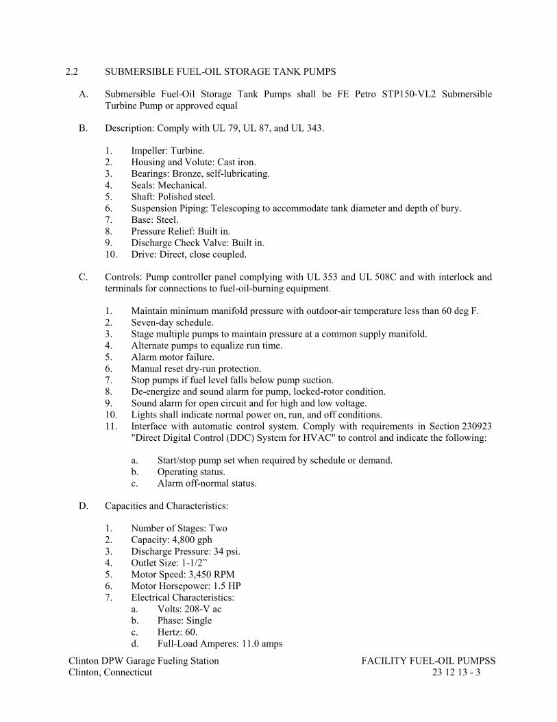
Clinton DPW Garage Fueling Station
Clinton, Connecticut
FACILITY FUEL-OIL PUMPSS
23 12 13 - 3
2.2 SUBMERSIBLE FUEL-OIL STORAGE TANK PUMPS
A. Submersible Fuel-Oil Storage Tank Pumps shall be FE Petro STP150-VL2 Submersible
Turbine Pump or approved equal
B. Description: Comply with UL 79, UL 87, and UL 343.
1. Impeller: Turbine.
2. Housing and Volute: Cast iron.
3. Bearings: Bronze, self-lubricating.
4. Seals: Mechanical.
5. Shaft: Polished steel.
6. Suspension Piping: Telescoping to accommodate tank diameter and depth of bury.
7. Base: Steel.
8. Pressure Relief: Built in.
9. Discharge Check Valve: Built in.
10. Drive: Direct, close coupled.
C. Controls: Pump controller panel complying with UL 353 and UL 508C and with interlock and
terminals for connections to fuel-oil-burning equipment.
1. Maintain minimum manifold pressure with outdoor-air temperature less than 60 deg F.
2. Seven-day schedule.
3. Stage multiple pumps to maintain pressure at a common supply manifold.
4. Alternate pumps to equalize run time.
5. Alarm motor failure.
6. Manual reset dry-run protection.
7. Stop pumps if fuel level falls below pump suction.
8. De-energize and sound alarm for pump, locked-rotor condition.
9. Sound alarm for open circuit and for high and low voltage.
10. Lights shall indicate normal power on, run, and off conditions.
11. Interface with automatic control system. Comply with requirements in Section 230923
"Direct Digital Control (DDC) System for HVAC" to control and indicate the following:
a. Start/stop pump set when required by schedule or demand.
b. Operating status.
c. Alarm off-normal status.
D. Capacities and Characteristics:
1. Number of Stages: Two
2. Capacity: 4,800 gph
3. Discharge Pressure: 34 psi.
4. Outlet Size: 1-1/2”
5. Motor Speed: 3,450 RPM
6. Motor Horsepower: 1.5 HP
7. Electrical Characteristics:
a. Volts: 208-V ac
b. Phase: Single
c. Hertz: 60.
d. Full-Load Amperes: 11.0 amps
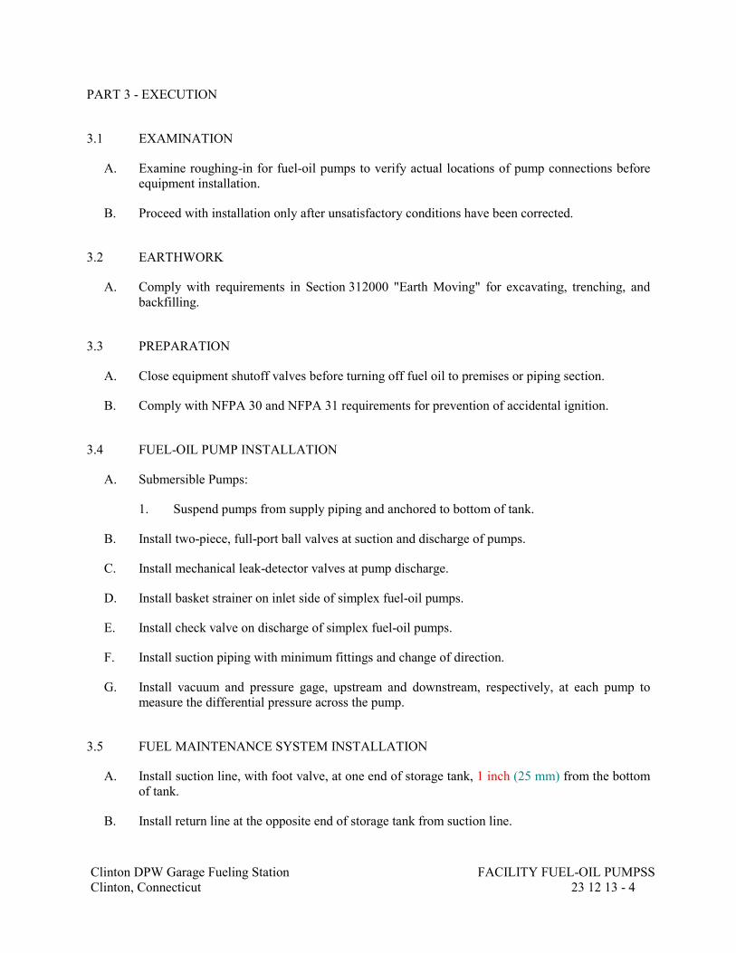
Clinton DPW Garage Fueling Station
Clinton, Connecticut
FACILITY FUEL-OIL PUMPSS
23 12 13 - 4
PART 3 - EXECUTION
3.1 EXAMINATION
A. Examine roughing-in for fuel-oil pumps to verify actual locations of pump connections before
equipment installation.
B. Proceed with installation only after unsatisfactory conditions have been corrected.
3.2 EARTHWORK
A. Comply with requirements in Section 312000 "Earth Moving" for excavating, trenching, and
backfilling.
3.3 PREPARATION
A. Close equipment shutoff valves before turning off fuel oil to premises or piping section.
B. Comply with NFPA 30 and NFPA 31 requirements for prevention of accidental ignition.
3.4 FUEL-OIL PUMP INSTALLATION
A. Submersible Pumps:
1. Suspend pumps from supply piping and anchored to bottom of tank.
B. Install two-piece, full-port ball valves at suction and discharge of pumps.
C. Install mechanical leak-detector valves at pump discharge.
D. Install basket strainer on inlet side of simplex fuel-oil pumps.
E. Install check valve on discharge of simplex fuel-oil pumps.
F. Install suction piping with minimum fittings and change of direction.
G. Install vacuum and pressure gage, upstream and downstream, respectively, at each pump to
measure the differential pressure across the pump.
3.5 FUEL MAINTENANCE SYSTEM INSTALLATION
A. Install suction line, with foot valve, at one end of storage tank, 1 inch (25 mm) from the bottom
of tank.
B. Install return line at the opposite end of storage tank from suction line.

Clinton DPW Garage Fueling Station
Clinton, Connecticut
FACILITY FUEL-OIL PUMPSS
23 12 13 - 5
3.6 LABELING AND IDENTIFYING
A. Install nameplates and signs on each fuel-oil pump. Comply with requirements in
Section 230553 "Identification for HVAC Piping and Equipment."
3.7 FIELD QUALITY CONTROL
A. Manufacturer's Field Service: Engage a factory-authorized service representative to test and
inspect components, assemblies, and equipment installations, including connections.
B. Perform the following tests and inspections with the assistance of a factory-authorized service
representative
1. Start fuel-oil transfer pumps to verify for proper operation of pump, and check for leaks.
2. Test and adjust controls and safeties. Replace damaged and malfunctioning controls and
equipment.
C. Fuel-oil pumps will be considered defective if they do not pass tests and inspections.
D. Prepare test and inspection reports.
3.8 DEMONSTRATION
A. Engage a factory-authorized service representative to train Owner's maintenance personnel to
adjust, operate, and maintain fuel-oil pumps
END OF SECTION 231213

SECTION 23 13 23
FACILITY ABOVEGROUND FUEL-OIL STORAGE TANKS
Clinton DPW Garage Fueling Station
Clinton, Connecticut
FACILITY ABOVEGROUND FUEL-OIL STORAGE TANKS
23 13 23 - 1
PART 1 - GENERAL
1.1 RELATED DOCUMENTS
A. Drawings and general provisions of the Contract, including General and Supplementary
Conditions and Division 01 Specification Sections, apply to this Section.
1.2 SUMMARY
A. Section Includes:
1. Insulated, steel, fuel-oil ASTs and accessories.
1.3 DEFINITIONS
A. AST: Aboveground storage tank.
1.4 ACTION SUBMITTALS
A. Product Data: For each type of product.
1. Include construction details, material descriptions, and dimensions of individual
components and profiles.
2. Include rated capacities, operating characteristics, electrical characteristics, and furnished
specialties and accessories.
3. Fuel-oil storage tank accessories.
B. Shop Drawings:
1. Include plans, elevations, sections, and ballast pads and anchors, and lifting or supporting
points.
2. Indicate dimensions, components, and location and size of each field connection.
3. Shop Drawing Scale: 1/4 inch per foot
1.5 INFORMATIONAL SUBMITTALS
A. Site Survey: Plans, drawn to scale, on which fuel-oil storage tanks are shown and coordinated
with other services and utilities.
B. Qualification Data: For qualified professional engineer.
C. Seismic Qualification Data: For ASTs, accessories, and components, from manufacturer.

Clinton DPW Garage Fueling Station
Clinton, Connecticut
FACILITY ABOVEGROUND FUEL-OIL STORAGE TANKS
23 13 23 - 2
1. Basis for Certification: Indicate whether withstand certification is based on actual test of
assembled components or on calculation.
2. Dimensioned Outline Drawings of Equipment Unit: Identify center of gravity and locate
and describe mounting and anchorage provisions.
3. Detailed description of equipment anchorage devices on which the certification is based
and their installation requirements.
D. Brazing certificates.
E. Welding certificates.
F. Field quality-control reports.
G. Sample Warranty: For special warranty.
1.6 CLOSEOUT SUBMITTALS
A. Operation and Maintenance Data: For fuel-oil equipment and accessories to include in
emergency, operation, and maintenance manuals.
1.7 QUALITY ASSURANCE
A. EPA Compliance: Comply with EPA and state and local authorities having jurisdiction. Include
recording of fuel-oil storage tanks and monitoring of tanks.
B. Steel Support Welding Qualifications: Qualify procedures and personnel according to
AWS D1.1/D1.1M, "Structural Welding Code - Steel."
1.8 WARRANTY
A. Special Warranty: Manufacturer agrees to repair or replace components of fuel-oil storage tanks
that fail in materials or workmanship within specified warranty period.
1. Storage Tanks:
a. Failures include, but are not limited to, the following when used for storage of fuel
oil at temperatures not exceeding 150 deg F:
1) Structural failures including cracking, breakup, and collapse.
2) Corrosion failure including external and internal corrosion of steel tanks.
b. Warranty Period: 30 years from date of Substantial Completion.

Clinton DPW Garage Fueling Station
Clinton, Connecticut
FACILITY ABOVEGROUND FUEL-OIL STORAGE TANKS
23 13 23 - 3
PART 2 - PRODUCTS
2.1 PERFORMANCE REQUIREMENTS
A. Engage a qualified professional to configure a complete fueling system solution including tank,
piping, probes and leak detection, inventory monitoring and control, dispenser access control,
reporting and regulatory compliance, piping thrust support and anchorage and electrical wiring.
Provide a complete submittal package identifying all elements of the proposed fueling system,
including a site layout plan and manufacturers material and equipment specifications for all
system components. The new proposed fueling system is described in detail in the plans and
specifications but generally shall consist of the following:
1. Demolition and disposal of existing UST, piping, dispensers, appurtenances, and
equipment
2. Remediation and disposal of any impacted soils based on testing to be performed by
others
3. New insulated dual wall diesel Aboveground Storage Tank (AST) including tank and
Interstitial ventilation, access stairs and platform, traffic protection, product and water
level sensors, pumps, electrical services, and filling spill containment.
4. New dispenser island including dispensers, dispenser sumps, lighting, traffic protection,
and concrete filling pad.
5. Two new electronic fuel dispensers (one gasoline, and one diesel) including access
control, electronic inventory management, vapor recovery, as well as hoses, nozzles, and
high hose retractor system (2 for each dispenser).
6. New tank, dispenser, and fuel line leak detection sensors and associated equipment
7. Conversion of nearby existing gasoline fueling system to supply new gasoline dispenser
including selective equipment demolition, new fuel piping (with secondary containment),
electrical services, dispenser sump, and connection to new tank monitoring and inventory
control equipment.
8. New fuel lines (diesel and gasoline) including valves and accessories
B. Seismic Performance: Factory-installed support attachments for AST shall withstand the effects
of earthquake motions determined according to ASCE/SEI 7.
1. The term "withstand" means "the unit will remain in place without separation of any parts
when subjected to the seismic forces specified and the unit will be fully operational after
the seismic event."
2.2 INSULATED, STEEL, FUEL-OIL AST
A. Tank shall be Highland Tank UL-2085 Fireguard thermal insulated FG Double Wall steel
aboveground storage tank or approved equal
B. Description: UL 142 and UL 2085, thermally insulated and fire-resistant, double-wall,
horizontal, steel tank; with primary- and secondary-containment walls and insulation and with
interstitial space.
C. Construction: Fabricated with welded, carbon steel and insulation; suitable for operation at
atmospheric pressure and for storing fuel oil with specific gravity up to 1.1 and with test
temperature according to UL 2085.
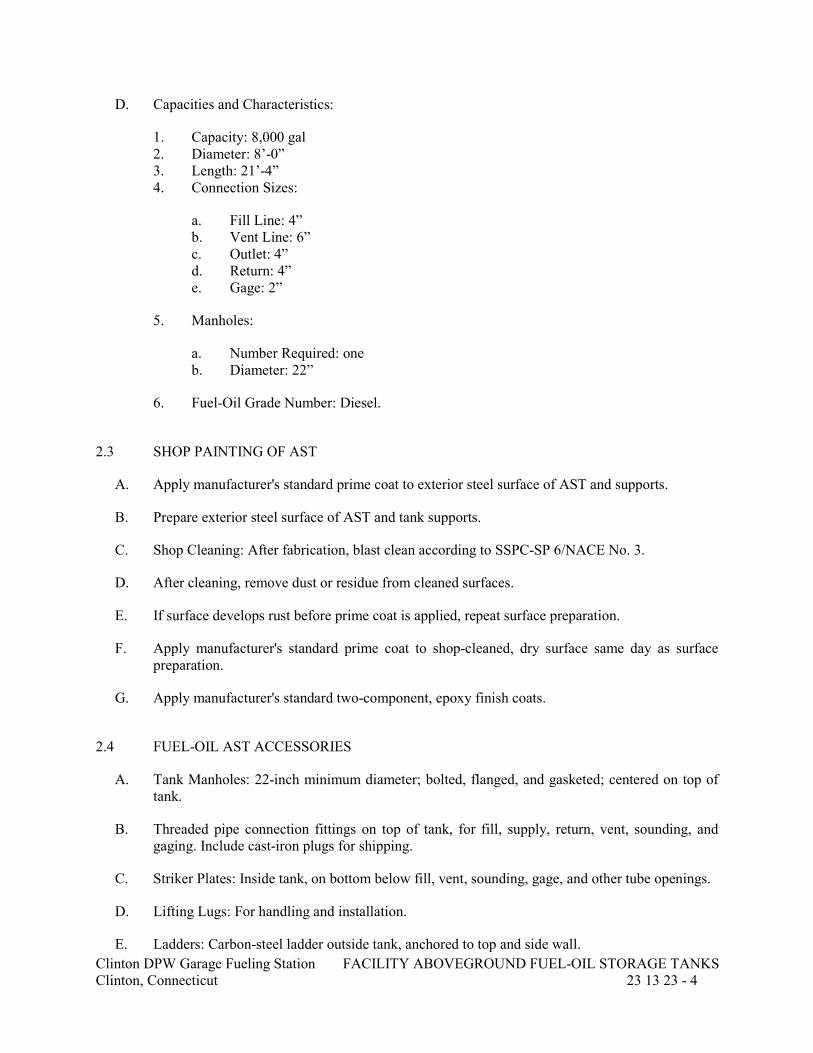
Clinton DPW Garage Fueling Station
Clinton, Connecticut
FACILITY ABOVEGROUND FUEL-OIL STORAGE TANKS
23 13 23 - 4
D. Capacities and Characteristics:
1. Capacity: 8,000 gal
2. Diameter: 8’-0”
3. Length: 21’-4”
4. Connection Sizes:
a. Fill Line: 4”
b. Vent Line: 6”
c. Outlet: 4”
d. Return: 4”
e. Gage: 2”
5. Manholes:
a. Number Required: one
b. Diameter: 22”
6. Fuel-Oil Grade Number: Diesel.
2.3 SHOP PAINTING OF AST
A. Apply manufacturer's standard prime coat to exterior steel surface of AST and supports.
B. Prepare exterior steel surface of AST and tank supports.
C. Shop Cleaning: After fabrication, blast clean according to SSPC-SP 6/NACE No. 3.
D. After cleaning, remove dust or residue from cleaned surfaces.
E. If surface develops rust before prime coat is applied, repeat surface preparation.
F. Apply manufacturer's standard prime coat to shop-cleaned, dry surface same day as surface
preparation.
G. Apply manufacturer's standard two-component, epoxy finish coats.
2.4 FUEL-OIL AST ACCESSORIES
A. Tank Manholes: 22-inch minimum diameter; bolted, flanged, and gasketed; centered on top of
tank.
B. Threaded pipe connection fittings on top of tank, for fill, supply, return, vent, sounding, and
gaging. Include cast-iron plugs for shipping.
C. Striker Plates: Inside tank, on bottom below fill, vent, sounding, gage, and other tube openings.
D. Lifting Lugs: For handling and installation.
E. Ladders: Carbon-steel ladder outside tank, anchored to top and side wall.

Clinton DPW Garage Fueling Station
Clinton, Connecticut
FACILITY ABOVEGROUND FUEL-OIL STORAGE TANKS
23 13 23 - 5
F. Supply Tube: Extension of supply piping fitting into tank, terminating 6 inches above tank
bottom and cut at a 45-degree angle.
G. Sounding and Gage Tubes: Extension of fitting into tank, terminating 6 inches above tank
bottom and cut at a 45-degree angle.
2.5 LIQUID-LEVEL GAGE SYSTEM
A. Description: Calibrated liquid-level gage system complying with UL 180 with floats or other
sensors and remote annunciator panel.
B. Annunciator Panel: With visual and audible, high-tank-level and low-tank-level alarms; fuel
indicator with registration in gallons; and overfill alarm. Include gage volume range that covers
fuel-oil storage capacity.
C. Controls: Electrical, operating on 120-V ac.
2.6 LEAK-DETECTION AND MONITORING SYSTEM
A. Cable and Sensor System: Comply with UL 1238.
1. Calibrated leak-detection and monitoring system with probes and other sensors and
remote alarm panel for fuel-oil storage tanks and fuel-oil piping.
2. Include fittings and devices required for testing.
3. Controls: Electrical, operating on 120-V ac.
4. Calibrated liquid-level gage complying with UL 180 with floats or other sensors and
remote annunciator panel.
5. Remote Annunciator Panel: With visual and audible, high-tank-level and low-tank-level
alarms; fuel indicator with registration in gallons; and overfill alarm. Include gage
volume range that covers fuel-oil storage capacity.
6. Controls: Electrical, operating on 120-V ac.
2.7 FUEL OIL
A. Diesel Fuel Oil: ASTM D 975, Grade Low Sulfur volatility.
2.8 SOURCE QUALITY CONTROL
A. Pressure test and inspect fuel-oil storage tanks, after fabrication and before shipment, according
to ASME and the following:
1. Horizontal, Double-Wall Steel ASTs: UL 142, STI F921, and STI R931.
B. Affix standards organization's code stamp.

Clinton DPW Garage Fueling Station
Clinton, Connecticut
FACILITY ABOVEGROUND FUEL-OIL STORAGE TANKS
23 13 23 - 6
PART 3 - EXECUTION
3.1 EXAMINATION
A. Examine roughing-in for aboveground fuel-oil storage tanks to verify actual locations.
B. Proceed with installation only after unsatisfactory conditions have been corrected.
3.2 EARTHWORK
A. Comply with requirements in Section 312000 "Earth Moving" for excavating, trenching, and
backfilling.
B. Allow for cast-in-place, concrete base.
3.3 FUEL-OIL AST INSTALLATION
A. Install tank bases and supports.
B. Concrete Bases: Anchor AST to concrete base according to equipment manufacturer's written
instructions and according to seismic codes at Project.
1. Construct concrete bases of dimensions indicated, but not less than 4 inches larger in both
directions than supported unit.
2. Place and secure anchorage devices. Use supported equipment manufacturer's setting
drawings, templates, diagrams, instructions, and directions furnished with items to be
embedded.
3. Install anchor bolts to elevations required for proper attachment to supported equipment.
4. Use 3000-psig, 28-day, compressive-strength concrete and reinforcement as specified in
Section 033000 "Cast-in-Place Concrete."
C. Connect piping and vent fittings.
D. Install ground connections.
E. Install tank leak-detection and monitoring devices.
F. Install steel ASTs according to STI R912.
G. Install insulated and concrete-vaulted, steel ASTs according to STI R942.
H. Fill storage tanks with fuel oil.
3.4 LIQUID-LEVEL GAGE SYSTEM INSTALLATION
A. Install liquid-level gage system. Install panel inside building where indicated.
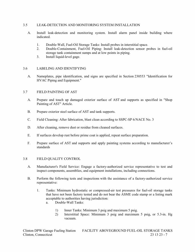
Clinton DPW Garage Fueling Station
Clinton, Connecticut
FACILITY ABOVEGROUND FUEL-OIL STORAGE TANKS
23 13 23 - 7
3.5 LEAK-DETECTION AND MONITORING SYSTEM INSTALLATION
A. Install leak-detection and monitoring system. Install alarm panel inside building where
indicated.
1. Double-Wall, Fuel-Oil Storage Tanks: Install probes in interstitial space.
2. Double-Containment, Fuel-Oil Piping: Install leak-detection sensor probes in fuel-oil
storage tank containment sumps and at low points in piping.
3. Install liquid-level gage.
3.6 LABELING AND IDENTIFYING
A. Nameplates, pipe identification, and signs are specified in Section 230553 "Identification for
HVAC Piping and Equipment."
3.7 FIELD PAINTING OF AST
A. Prepare and touch up damaged exterior surface of AST and supports as specified in "Shop
Painting of AST" Article.
B. Prepare exterior steel surface of AST and tank supports.
C. Field Cleaning: After fabrication, blast clean according to SSPC-SP 6/NACE No. 3
D. After cleaning, remove dust or residue from cleaned surfaces.
E. If surfaces develop rust before prime coat is applied, repeat surface preparation.
F. Prepare surface of AST and supports and apply painting systems according to manufacturer’s
standards
3.8 FIELD QUALITY CONTROL
A. Manufacturer's Field Service: Engage a factory-authorized service representative to test and
inspect components, assemblies, and equipment installations, including connections.
B. Perform the following tests and inspections with the assistance of a factory-authorized service
representative:
1. Tanks: Minimum hydrostatic or compressed-air test pressures for fuel-oil storage tanks
that have not been factory tested and do not bear the ASME code stamp or a listing mark
acceptable to authorities having jurisdiction:
a. Double-Wall Tanks:
1) Inner Tanks: Minimum 3 psig and maximum 5 psig.
2) Interstitial Space: Minimum 3 psig and maximum 5 psig, or 5.3-in. Hg
vacuum.

Clinton DPW Garage Fueling Station
Clinton, Connecticut
FACILITY ABOVEGROUND FUEL-OIL STORAGE TANKS
23 13 23 - 8
b. Where vertical height of fill and vent pipes is such that the static head imposed on
the bottom of the tank is greater than 10 psig, hydrostatically test the tank and fill
and vent pipes to a pressure equal to the static head thus imposed.
c. Maintain the test pressure for one hour.
C. ASTs will be considered defective if they do not pass tests and inspections.
D. Prepare test and inspection reports.
END OF SECTION 231323
SECTION 23 14 13
FACILITY FUEL-OIL DISPENSER
Clinton DPW Garage Fueling Station
Clinton, Connecticut
FACILITY FUEL-OIL DISPENSER
23 14 13 - 1
PART 1 - GENERAL
1.1 RELATED DOCUMENTS
A. Drawings and general provisions of the Contract, including General and Supplementary
Conditions and Division 01 Specification Sections, apply to this Section.
1.2 SUMMARY
A. Section Includes:
1. Fuel-oil dispenser with integral fuel control system.
1.3 ACTION SUBMITTALS
A. Product Data: For each type of product.
1. Include construction details, material descriptions, and dimensions of individual
components and profiles.
2. Include, where applicable, rated capacities, operating characteristics, electrical
characteristics, and furnished specialties and accessories.
B. Shop Drawings: For fuel-oil dispensers.
1. Include construction details and dimensions of individual components for fuel-oil
dispensers.
2. Include rated capacities, operating characteristics, electrical characteristics, and furnished
specialties and accessories.
3. Scale: 1/4 inch per foot.
C. Delegated-Design Submittal: For fuel-oil dispensers.
1. Detail fabrication and assembly of all system components.
2. Detail fabrication and assembly of system components.
1.4 INFORMATIONAL SUBMITTALS
A. Field quality-control reports.
B. Sample Warranty: For special warranty.

Clinton DPW Garage Fueling Station
Clinton, Connecticut
FACILITY FUEL-OIL DISPENSERS
23 14 13 - 2
1.5 CLOSEOUT SUBMITTALS
A. Operation and Maintenance Data: For fuel-oil dispensers and fuel control systems to include in
emergency, operation, and maintenance manuals.
PART 2 - PRODUCTS
2.1 PERFORMANCE REQUIREMENTS
A. Delegated Design: Engage a qualified professional to develop a detailed comprehensive fuel-oil
dispensing system with fuel control, using performance requirements and design criteria
indicated.
B. Electrical Components, Devices, and Accessories: Listed and labeled as defined in NFPA 70, by
a qualified testing agency, and marked for intended location and application.
C. Listed and labeled for fuel-oil service by an NRTL acceptable to authorities having jurisdiction.
2.2 FUEL-OIL DISPENSERS
A. Fuel-oil dispensers shall be Wayne Fueling Systems Select Model 3/G7242D/2GHJ/D4JKS3 or
approved equal
B. Capacities and Characteristics:
1. Electronic displays. Mechanical registers are not acceptable.
a. For each hose, matching backlit 6-digit 1" liquid crystal (LCD) gallons display on
each side of dispenser.
b. Display backup for a minimum of 15 minutes in the event of power loss.
c. Four-character 1/2" LCD operator message display for each hose to denote
authorization status, cut-off limit, etc.
d. All displays covered with tempered or double-strength glass (plastic not
acceptable).
2. Electronic register and lights - 115VAC, 60 hz.
3. Electromechanical totalizer, 7-digit non-resettable, for each hose located on dispenser
sides for inventory control.
4. Electronic 6-digit non-resettable and resettable totalizers per hose.
5. Diagnostics including log of last 50 errors/events. Dispenser software configurable and
downloadable from PC.
6. Dual pulse output interface for each hose for connection to fuel control and tank
monitoring systems.
7. Cabinet: Lower hydraulic cabinet top, sides, and base constructed from stainless steel.
a. Top register cabinet constructed from galvannealed steel with powder-coated
black finish.
b. Stainless steel lower doors.
c. Hinged lower doors for easy service access without having to remove panels.
8. Lighted brand panels labeled ‘Diesel’ for the diesel dispenser and ‘Gasoline’ for the
gasoline dispenser.

Clinton DPW Garage Fueling Station
Clinton, Connecticut
FACILITY FUEL-OIL DISPENSERS
23 14 13 - 3
9. Island-oriented nozzle boots located on sides of cabinet with lift-to-start nozzle hooks to
turn on/off dispenser.
a. Nozzle boots shall accommodate UL standard interchangeable nozzles and short
spout vapor recovery nozzles. Diesel nozzles shall be provided with green covers,
and gasoline nozzles with black covers . Nozzles shall be OPW 11BP-0992-E85
and OPW 11A-00900-B20 or approved equal.
b. High mount hose mast for each hose outlet with heavy duty spring base and top
swivel connector to ease handling of hose.
c. Hoses shall be VSTaflex with Sentry Breakaway System or approved equal
10. Two (2) positive displacement, two-piston meters with integral hall effect pulsers with no
moving parts to wear out.
11. Electronic calibration without the need to set mechanical adjusters.
12. One (1) proportional solenoid valve for each hose, programmable through electronic
register to set maximum flow rate.
13. One (1) internal filter with 30-micron element for each hose to help ensure product
purity.
14. Two (2) 1" discharge outlets with ¾” reducing bushings so that either a ¾” or 1” hoses
may be used.
15. One (1) 1.5" NPT inlet for one product.
16. Explosion-proof junction box in hydraulic cabinet to make all dispenser power and
control wiring terminations.
17. Dispenser shall include one integral in-dispenser terminal to control access to that
dispenser. In-dispenser terminal shall include:
a. CPU with 32-bit embedded processor, 5 USB ports, & Windows CE operating
system
b. 4 x 3 membrane keypad, 0-9, clear, & enter keys, for user entries
18. HID ProxPoint Plus 6005B 125khz proximity reader for HID Prox cards or tags.
19. Thermostatically-controlled heater for cold temperatures.
20. User prompts shall be settable by individual vehicle and/or employee (e.g. Enter
Odometer, Enter Hours, etc.)
21. Dispenser shall be configurable for the access id to identify (one of):
a. vehicle with optional keypad entry of the employee number
b. employee with optional keypad entry of the vehicle number
22. Dispensers shall have IP address & 4-port ethernet switch for connection to controller,
other dispensers, or LAN.
23. Dispenser shall authorize & record transactions independently of controller in case
communication is interrupted.
24. Recorded transactions shall be backed up in at least two places in addition to RAM to
provide redundancy.
25. Recorded transactions shall be able to be moved to controller with a USB key if
communication is interrupted.
26. Each dispenser shall have the capacity to store up to one year of transactions if not
transmitted to the controller.
27. Warranty: One year parts and labor.
28. Standards/Approvals: UL listed, FCC, W&M approvals.
2.3 SYSTEM CONTROLLER
A. System Controller shall be Wayne Fueling Systems iX Fleet Fuel Controller WU015626-0001
or approved equal

Clinton DPW Garage Fueling Station
Clinton, Connecticut
FACILITY FUEL-OIL DISPENSERS
23 14 13 - 4
B. Capacities and Characteristics:
1. System shall include a central controller for controlling & reporting fueling activity from
the dispensers.
a. Only one controller shall be required for all sites.
b. Controller shall be designed for industrial applications & include a fan-less SBC
with 120GB solid state drive.
c. Controller shall include battery back-up for graceful shutdown with loss of power.
d. Controller shall include Windows POS Ready operating system.
e. Controller shall include 19" color LCD monitor, keyboard, & mouse; 2 USB ports;
& Ethernet port.
f. Controller shall be designed to be either desk or wall-mounted.
g. Controller shall communicate to the dispensers via a direct LAN cable connection
or over a local area network.
h. Data for authorizing & controlling fueling transactions shall be entered at the
controller & downloaded to each dispenser.
i. Each dispenser shall independently control the transactions without
communicating to the controller.
j. Controller & dispensers shall communicate automatically every 5 minutes, or on
demand, to exchange data.
2. Vehicle controls shall include:
a. Authorized fuel site(s)
b. Authorized product(s)
c. Maximum fuel per transaction
d. Maximum fuelings per day
e. Odometer reasonability minimum and maximum miles
3. Employee controls shall include:
a. Authorized fuel site(s)
b. Authorized vehicle types
c. Maximum fuelings per day
4. Data shall be able to be entered directly into the database, or optionally through an excel
template.
5. System shall be able to handle a total of 500 vehicles and employees.
6. Software shall include a management dashboard showing the status of all fueling sites on
a single screen.
7. Dashboard shall provide alerts of equipment, inventory, or communication issues; &
transaction errors.
8. Dashboard shall include key graphs and tables for monitoring fueling activity.
9. An ad hoc report generator shall be included to create custom transaction reports.
10. Reports shall be able to be filtered for specific or ranges of data and time/date range.
11. Transaction data in reports shall include:
a. Site number and name
b. Transaction number
c. Date/Time
d. Department number and name
e. Vehicle number and name
f. Employee number and name
g. Fueling point number
h. Product number and name
i. Quantity
j. Odometer or hours
k. Miles traveled or hours used

Clinton DPW Garage Fueling Station
Clinton, Connecticut
FACILITY FUEL-OIL DISPENSERS
23 14 13 - 5
l. Unit price or cost
m. Total price or cost
n. Miles per gallon
o. Cost per mile or hour
p. Errors
q. Subtotals and grand totals
12. A transaction export file in XML format shall be created for use by third party software
or Excel.
13. Warranty: One year parts and labor.
14. Standards/Approvals: C-UL-US listed, FCC approval
PART 3 - EXECUTION
3.1 EXAMINATION
A. Examine site conditions to ensure that manufacturers recommended conditions exist prior to
dispenser and system controller installation is performed.
B. Proceed with installation only after unsatisfactory conditions have been corrected.
3.2 PREPARATION
A. Close equipment shutoff valves before turning off fuel oil to premises or piping section.
B. Comply with NFPA 30 and NFPA 31 requirements for prevention of accidental ignition.
3.3 FUEL-OIL DISPENSER INSTALLATION
A. Ship, handle, and store dispenser hardware and equipment in accordance with manufacturers
written instructions.
B. Install, configure, and test all systems and equipment in conformance with all manufacturers
written installation instructions and conditions. Provide written results of system testing.
Provide a detailed configuration report to document system setup configuration.
C. Contractor shall provide a factory-authorized technician with a minimum of five (5) years of
experience in setup and configuration of the systems to be installed. Testing and configuration
of dispenser systems shall be in conformance with manufacturers recommendations. Configure
system setup only after detailed consultation with the Owner and Engineer. Technician shall
perform a detailed review of operational options and complete setup to conform fully to Owner
desired system configuration decisions.

Clinton DPW Garage Fueling Station
Clinton, Connecticut
FACILITY FUEL-OIL DISPENSERS
23 14 13 - 6
3.4 SYSTEM CONTROLLER INSTALLATION
A. Ship, handle, and store system controller hardware in accordance with manufacturers written
instructions. System controller shall be installed within the Clinton Public Works Garage
administrative offices in a location to be determined by the Owner.
B. Install, configure, and test all systems and equipment in conformance with all manufacturers
written installation instructions and conditions. Provide written results of system testing.
Provide a detailed configuration report to document system setup configuration
C. Contractor shall provide a factory-authorized technician with a minimum of five (5) years of
experience in setup and configuration of the systems to be installed. Testing and configuration
of system controller shall be in conformance with manufacturers recommendations. Configure
system setup only after detailed consultation with the Owner and Engineer. Technician shall
perform a detailed review of operational options and complete setup to conform fully to Owner
desired system configuration decisions.
3.5 LABELING AND IDENTIFYING
A. Install nameplates and signs on each fuel-oil dispenser. Comply with requirements in
Section 230553 "Identification for HVAC Piping and Equipment."
3.6 DEMONSTRATION
A. Engage a factory-authorized service representative to train Owner's maintenance personnel to
adjust, operate, and maintain fuel-oil pumps
END OF SECTION 231213

Clinton DPW Garage Fueling Station GENERAL REQUIREMENTS FOR ELECTRICAL WORK
Clinton, Connecticut 26 01 00 - 1
SECTION 26 01 00
GENERAL REQUIREMENTS FOR ELECTRICAL WORK
PART 1 - GENERAL
1.1 RELATED DOCUMENTS
A. Drawings and general provisions of the Contract, including General and Supplementary
Conditions and Division 1 Specification Sections, apply to this Section.
1. General Conditions, Supplementary Conditions and Division 1 paragraphs may be
repeated in this Division for emphasis or for inclusion of more stringent/additional
related requirements. Such repetition shall not be construed to reduce the requirements of
those Divisions nor to eliminate other requirements under those Divisions.
2. Contractor is responsible for Specification Section 019113 – General Commissioning
Requirements as it pertains to their work, and shall participate in and perform
commissioning team activities.
1.2 SUMMARY
A. This Section includes General Requirements for Electrical Work.
B. Related Sections include the following:
1. Division 01 Section “Closeout Procedures” for Warranties.
2. Division 01 Section “Demonstration and Training”.
3. Division 23 Section “Instrumentation and Control for HVAC” for installation, wiring and
connections of controls.
4. Division 31 Section “Earth Moving” for building services.
1.3 SHOP DRAWING SUBMITTALS
A. Prepare and submit Shop Drawings through the Contractor to the Architect for review.
B. The selection and intention to use a product specified by name shall not excuse the need for
timely submission of shop drawings for that product.
C. Prior to submitting shop drawings, submit for review preliminary list of intended or proposed
manufacturers for all items for which shop drawings are required.
D. Submission of shop drawings of an unnamed manufacturer shop drawings at variance with the
Contract Documents is not a proper request for substitution.
E. Samples that are submitted in lieu of shop drawings shall be clearly identified and shall be
submitted in duplicate. Only one sample will be returned and that accepted sample shall be
Clinton DPW Garage Fueling Station GENERAL REQUIREMENTS FOR ELECTRICAL WORK
Clinton, Connecticut 26 01 00 - 2
kept available at appropriate job site office. Accepted sample retained by Architect will be kept
available at Architect’s home office.
F. Upon completion of shop drawing review, shop drawings will be returned, marked with one of
following notations: No Exception Taken, Revise as Noted, Revise and Resubmit, or Rejected.
Only products whose shop drawings are marked “No Exception Taken” or “Revise as Noted”
shall be used on the project.
G. Submittals shall include the following information:
1. Descriptive and product data necessary to verify compliance with Contract Documents.
2. Manufacturer’s specifications including materials of construction, metal gauge, thickness
and finish.
3. Certified dimensional drawings including clearances required for maintenance or access.
4. Performance data, ratings, operating characteristics, and operating limits.
5. Electrical ratings and characteristics.
6. Wiring and control diagrams, where applicable.
7. Certifications requested, including UL label or listing.
8. List of accessories which are required but are not being provided by the product
manufacturer or are not being furnished under this Section. Identify the Section(s) under
which the accessories are being furnished.
H. In addition, submittals shall be clearly marked for the following:
1. Specification Section and Paragraph, or Drawing Schedule/Note/Detail/etc., where
equipment is specified.
2. Equipment or fixture identification corresponding to that used in Contract Documents.
3. Accessories and special or non-standard features and materials which are being furnished.
1.4 INTENT
A. It is the intent of the Contract Documents to require finished work, tested and ready for
operation.
B. It is not intended that Contract Documents show every pipe, wire, conduit, fitting and
appurtenance; however, such parts as may be necessary to complete the systems in accordance
with best trade practice and Code requirements and to Architect’s satisfaction shall be deemed
to be included.
C. Drawings are diagrammatic and indicate the general arrangement of systems and work included
in the Contract. DO NOT SCALE THE DRAWINGS.
1.5 PRODUCT SELECTION
A. Contractor’s options for selecting products are limited by Contract Document requirements and
governing regulations and are not controlled by industry traditions or procedures experienced
by Contractor on previous construction projects. Required procedures include, but are not
necessarily limited to, following various methods of specifying:

Clinton DPW Garage Fueling Station GENERAL REQUIREMENTS FOR ELECTRICAL WORK
Clinton, Connecticut 26 01 00 - 3
1. Single Product Manufacturer Named: Provide product indicated. Advise Architect, and
obtain instructions before proceeding, when named product is known to be unacceptable or
not feasible.
2. Two or More Manufacturers’ Products Named: Provide one of the named products, at
Contractor’s option, but excluding products which do not comply with requirements. Do
not provide, nor offer to provide, an unnamed product unless named products do not
comply with requirements or are not feasible.
3. “Acceptable Equivalent” or “Or Equal”: Where named products are accompanied by this
term or words of similar effect, provide named products or propose substitute product
according to SUBSTITUTIONS paragraph.
4. Standards, Codes and Regulations: Where specification requires only compliance with a
standard, code or regulation, Contractor may select any product which complies with
requirements of that standard, code or regulation.
5. Performance Requirements: Provide products which comply with specific performances
indicated and which are recommended by manufacturer (in published product literature or
by individual certification) for application intended. Overall performance of product is
implied where product is specified with only certain specific performance requirements.
6. Prescriptive Requirements: Provide products which have been produced in accordance
with prescriptive requirements using specified materials and components, and complying
with specified requirements for fabricating, finishing, testing and other manufacturing
processes.
7. Visual Matching: Where matching with an established material is required, Architect’s
judgment of whether proposed product matches established material shall be final. Where
product specified does NOT match established material, propose substitute product
according to SUBSTITUTIONS paragraph. Follow requirements for CHANGE ORDERS,
also, if matching product within cost category of specified product is not available.
8. “Color as Selected by Architect”: Unless otherwise noted, where specified product
requirements include “Color as Selected by Architect” or words of similar effect, the
selection of manufacturer and basic product complying with Contract Documents is
Contractor’s option and subsequent selection of color is Architect’s option.
B. Inclusion by name, of more than one manufacturer or fabricator, does not necessarily imply
acceptability of standard products of those named. All manufacturers, named or proposed, shall
conform, with modification as necessary, to criteria established by contract documents for
performance, efficiency, materials and special accessories.
1.6 SUBSTITUTIONS
A. Contractor shall also comply with the Architect’s substitution form located in Division 01.
B. Contractor’s request for substitution may be submitted only after award of Contract. Requests
shall be in writing on Contractor’s letterhead and shall include:
1. Contractor’s detailed comparison of significant qualities between specified item and
proposed substitution.
2. Statement of effect on construction time, coordination with other affected work, and cost
information or proposal.
3. Contractor’s statement to the effect that proposed substitution will result in overall work
equal to, or better than, work originally intended.

Clinton DPW Garage Fueling Station GENERAL REQUIREMENTS FOR ELECTRICAL WORK
Clinton, Connecticut 26 01 00 - 4
C. Substitution requests will be considered: If extensive revisions to Contract Documents are not
required; if changes are in keeping with general intent of Contract Documents; if submitted in
timely and proper manner, fully documented; and if one or more of following conditions is
satisfied; all as judged by Architect:
1. Where request is directly related to “acceptable equivalent” clause, “or equal” clause or
words of similar effect in Contract Documents.
2. Where specified product, material or method can not be provided within Contract Time; but
not as a result of Contractor’s failure to pursue the work promptly or to coordinate various
activities properly.
3. Where specified product, material or method can not be provided in manner which is
compatible with other materials of the work and where Contractor certifies that proposed
substitution is compatible.
4. Where specified product, material or method can not be properly coordinated with other
materials of the work and where Contractor certifies that proposed substitution can be
properly coordinated.
5. Where specified product, material or method can not be warranted as required and where
Contractor certifies that proposed substitution can be so warranted.
6. Where specified product, material or method can not be used without adversely affecting
Owner’s insurance coverage on completed work and where Contractor certifies that
proposed substitution can be so used.
7. Where specified product, material or method will encounter other substantial non-
compliance which are not possible to otherwise overcome except by using proposed
substitution.
8. Where specified product, material or method can not receive required approval by
governing authority and proposed substitution can be so approved.
9. Where substantial advantage is offered to the Owner; in terms of cost, time, energy
conservation or other valuable considerations; after deducting offsetting responsibilities
that Owner may be required to bear, including additional compensation to Architect for
redesign and evaluation services, increased cost of other work by Owner or separate
contractors, and similar considerations.
D. The burden is upon the Contractor, supplier and manufacturer to satisfy Architect that:
1. Proposed substitute is equal to, or superior to, the item specified.
2. Intent of the Contract Documents, including required performance, capacity, efficiency,
quality, durability, safety, function, appearance, space clearances and delivery date, will be
equaled or bettered.
E. Submission of shop drawings of unspecified manufacturer or shop drawings at variance with
the Contract Documents is not a proper request for substitution.
F. Changes in work of other trades, such as structural supports, which are required as a result of
substitution and the associated costs for such changes shall be the complete responsibility of
Contractor proposing substitution. Except as noted in subparagraph 1.6.C.9 above, there shall
be no additional expense to the Owner.

Clinton DPW Garage Fueling Station GENERAL REQUIREMENTS FOR ELECTRICAL WORK
Clinton, Connecticut 26 01 00 - 5
1.7 SAMPLES
A. Submit samples as requested by Architect/Engineer and at no additional cost to the owner.
1.8 RECORD DRAWINGS
A. Furnish and keep on the job at all times, one complete and separate set of blackline prints of the
Electrical work.
B. As work progresses, record changes, revisions and additions to Architectural and Electrical
work clearly, neatly, accurately and promptly. Items to be indicated include but are not limited
to:
1. Dimensional change
2. Revision to Drawing detail
3. Location and depth of underground utility
4. Revision to conduit routing
5. Revision to electrical circuitry
6. Actual equipment location
7. Ductbank size and routing
8. Location of concealed internal utility
9. Changes made by Change Order
10. Details not on original Contract Drawings
11. Information on concealed elements which would be difficult to identify or measure later
C. Indicate daily progress on these prints by coloring in the various lines, fixtures, apparatus and
associated appurtenances as they are erected.
D. Approval of requisition for payment for work installed will not be given unless supported by
record prints as required above.
E. At the conclusion of work, prepare record drawings on reproducible mylar sepias. Submit
record drawings for review by Architect. Refer to DIVISION 01, General Conditions and
Supplementary Conditions for further requirements.
1.9 OPERATING AND MAINTENANCE MANUALS
A. Submit for review operating and maintenance manuals for each system or piece of equipment,
at least two weeks prior to request for acceptance of same. Upon acceptance, furnish six copies
of each manual (or greater quantity if otherwise specified under DIVISION 01) to Architect for
transmittal to Owner. Operating and maintenance manual shall include:
1. Description of Unit (System) and Component Parts, including function, normal operating
characteristics and limiting conditions, performance curves, engineering data and tests, and
complete nomenclature and manufacturer’s number for replaceable parts.
2. Operating Procedures, including start-up, break-in, routine and normal operating
instructions; regulation, control, stopping, shutdown and emergency instructions; summer
and winter operating instructions; and any special operating instructions.
Clinton DPW Garage Fueling Station GENERAL REQUIREMENTS FOR ELECTRICAL WORK
Clinton, Connecticut 26 01 00 - 6
3. Maintenance Procedures, including routine operations, guide to trouble-shooting;
disassembly, repair and reassemble; alignment, adjusting and checking; servicing and
lubrication schedule, and list of lubricants; manufacturer’s installation and maintenance
bulletins and related information.
4. Sequence of Operation and Control Diagrams, corrected for as-built conditions.
5. Parts List, including illustrations, assembly drawings and diagrams required for
maintenance, predicted life of parts subject to wear, and recommendations for stocking
spare parts.
6. Copies of accepted shop drawings, charts and diagrams.
7. Names, addresses and telephone numbers of manufacturer’s representative and Service
Company.
8. Other data, as required under pertinent Sections of these Specifications.
9. Letters from each manufacturer certifying that his equipment was properly installed and is
operating in accordance with manufacturer’s intent.
1.10 GUARANTEE
A. Furnish standard manufacturers’ guarantees for work under this Division. Such guarantees
shall be in addition to, and not in lieu of, other liabilities under the law or by other provisions of
the Contract Documents.
B. Materials, equipment and workmanship shall carry the standard warranty against defects in
material and workmanship. Failure which may develop due to defective or improper material,
equipment, workmanship or design shall be made good, forthwith, by and at the expense of the
Contractor, including damage done to areas, materials and other systems resulting from this
failure.
C. Guarantee that all elements of the systems are of sufficient capacity to meet the specified
performance requirements as set forth in Contract Documents.
D. Upon receipt of notice from Owner of a failure of system(s) or component(s) during the
guarantee period, replace affected components within reasonable time period at no additional
cost.
E. Before final request for payment, furnish written guarantee covering above requirements.
1.11 EXAMINATION OF SITE AND CONTRACT DOCUMENTS
A. Before submitting prices or beginning work, thoroughly examine the site and the Contract
Documents.
B. No claim for extra compensation will be recognized if difficulties are encountered which would
have been revealed by examination of site conditions and Contract Documents prior to
executing Contract.
C. Where discrepancies occur within Contract Documents, notify Architect, in writing, or
discrepancy and request clarification. Until notified of Architect’s decision, include item or
arrangement of better quality, greater quantity or higher cost in Contract price.

Clinton DPW Garage Fueling Station GENERAL REQUIREMENTS FOR ELECTRICAL WORK
Clinton, Connecticut 26 01 00 - 7
1. For material, device and equipment identified on Contract Drawings by manufacturer and
model: Check Specification for ancillary requirements such as pilot lights or alarms, and
include same with furnished item. If Specifications require different model, notify
Engineer of discrepancy and request clarification.
D. Notify Engineer, in writing, of materials and apparatus believed to be omitted, inadequate or
unsuitable, or in violation of laws, ordinances, rules or regulations of authorities having
jurisdiction. In absence of such written notice, it is mutually agreed that bid price for work
under each Section has included the cost of items required for acceptable satisfactory
functioning of entire system.
1.12 DEFINITIONS
A. Where more than one material, item, or grade is listed in same paragraph, “Design Based” is
preferred choice.
B. The following terms are used in this Division and are defined as follows:
1. “Provide”: To furnish and install, ready for safe and regular operation the item, material or
service indicated.
2. “Furnish”: To purchase, acquire and deliver to the site, complete with related accessories.
3. “Install”: To erect, mount and connect completely, by acceptable methods.
4. “Work”: Labor, materials, equipment, apparatus, controls and accessories required for
proper and complete installation.
5. “Concealed”: Embedded in masonry or other construction; or installed in furred spaces,
trenches or crawl spaces; or installed within double partitions or hung ceilings; or in
enclosures.
6. “Exposed”: Visible to building occupants, excluding mechanical room and utility tunnel
locations.
7. “Acceptable equivalent” or “Equal”: Of weight, size, design, capacity and efficiency to
meet requirements specified and shown, and of acceptable manufacturer, as determined in
the opinion of the Architect.
8. “Acceptable”: Acceptable, as determined in the opinion of the Architect.
9. “Contractor”: General Contractor.
10. “Named” Product: Manufacturer’s name for product, as recorded in published documents
of latest issue as of date of Contract Documents. Obtain Architect’s permission before
using products of later or earlier model.
C. Standards, specifications and tests of following technical societies, organizations and
governmental bodies, as referenced in Contract Documents, are hereby made part of Contract
Documents.
1. IBC: International Building Code.
2. IES: Illuminating Engineering Society
3. ANSI: American National Standards Institute
4. ASTM: American Society for Testing and Materials
5. EPA: Environmental Protection Agency
6. FSSC: Federal Specification
7. IECC: International Energy Conservation Code

Clinton DPW Garage Fueling Station GENERAL REQUIREMENTS FOR ELECTRICAL WORK
Clinton, Connecticut 26 01 00 - 8
8. IEEE: Institute of Electrical and Electronics Engineers
9. IMC: International Mechanical Code
10. IRI: Industrial Risk Insurers
11. ISO: Insurance Services Office
12. NBS: National Bureau of Standards
13. NEC: National Electrical Code
14. NECA: National Electrical Contactors Association
15. NEMA: National Electrical Manufacturers Association
16. NETA: National Electrical Testing Association
17. NFPA: National Fire Protection Association
18. NSC: National Safety Council
19. OSHA: Occupational Safety and Health Administration
20. UL: Underwriters Laboratories
D. CODE: Codes and regulations of the Federal, State and local governments and of utility
companies having jurisdiction, as appropriate.
E. Use of singular or plural reference form in these Specifications shall not be construed to limit
number of units required. Specifications are intended to define quality and performance
characteristics; quantity of units supplied shall be as needed to meet requirements as specified
and as shown on Contract Documents.
1.13 LAWS, ORDINANCES AND CODES
A. Contractor shall comply with laws, ordinances, rules and regulations of Local, State and
Federal authorities having jurisdiction; and shall comply with rules and regulations of National
Board of Fire Underwriters, National Electrical Code and local utility companies.
B. Contract Documents shall govern whenever they are more stringent than Code requirements.
PART 2 - PRODUCTS
2.1 GENERAL PRODUCT REQUIREMENTS
A. Products shall be undamaged and unused at time of installation and shall be complete with
accessories, trim, finish, safety guards and other devices and details needed for complete
installation and for intended use.
B. Where available, products shall be standard products of types which have been produced and
use previously and successfully on other projects and in similar applications.
C. Where products by their nature and their use are likely to need replacement parts on future date,
for maintenance and repair or replacement work, products shall be standard domestically
produced products likely to have such parts available to Owner in future.

Clinton DPW Garage Fueling Station GENERAL REQUIREMENTS FOR ELECTRICAL WORK
Clinton, Connecticut 26 01 00 - 9
D. Labels and stamps which are required for observation after installation shall be located on
accessible surfaces which, in occupied spaces, are not conspicuous. Other labels and stamps
shall be located on concealed surfaces.
PART 3 - EXECUTION
3.1 ARRANGEMENT OF WORK
A. Consult Architectural Contract Drawings and Details for exact locations of fixtures and
equipment. If exact location is not given, obtain information from Architect. Verify
measurements in field; base measurements on Architect’s established benchmarks.
B. Install work as closely as possible to layouts shown on Contract Drawings. Modify work as
necessary to:
1. Provide maximum possible headroom and space clearance on each side.
2. Provide adequate clearance and ready access to all parts of the work, for inspection,
operation, safe maintenance and repair, and code conformance.
3. Coordinate and arrange work to avoid conflicts with work of other trades, to avoid
unnecessary cutting and patching, and as needed for satisfactory space conditions shown on
coordination drawing submittals.
4. Where space appears inadequate, consult Architect before proceeding with installation.
C. Work shall present a neat coordinated appearance.
3.2 COORDINATION
A. Examine Contract Documents and coordinate with Contractor and other trades as necessary to
facilitate the progress of the work.
B. Each trade shall keep Contractor and other trades fully informed as to shape, size, and locations
of openings, chases, equipment, panels, access doors, sleeves, inserts and anchor bolts required;
whether temporary or permanent. Coordinate sizes, depths, fill and bedding requirements with
excavation trades. Give sufficient advance notice so that coordination may be completed in
advance. If information is not furnished in proper and timely fashion, the trade involved shall
do own cutting and patching or have same done by Contractor, without additional cost to
Owner.
C. Particular emphasis is placed on timely installation of major apparatus and furnishing of other
trades and Contractor with relevant information.
D. Do not install a system until critical components of system and related systems have been
coordinated and applicable shop drawings have been accepted.
3.3 WORKMANSHIP

Clinton DPW Garage Fueling Station GENERAL REQUIREMENTS FOR ELECTRICAL WORK
Clinton, Connecticut 26 01 00 - 10
A. Work covered under this Division shall be constructed and finished in every respect in a
workmanlike and substantial manner.
B. Equipment and materials shall be new, of first quality, selected and arranged to fit properly into
spaces indicated.
C. Obtain detailed information from manufacturer as to proper methods for installation and
connections. This includes such tests as equipment manufacturer recommends. Where
documentation regarding installation is not obtainable, work shall be installed in accordance
with best trade practice.
1. Unless specifically indicated otherwise on Contract Documents, equipment and materials
shall be installed in accordance with manufacturer’s recommendations.
2. Notify Architect of conflicts between manufacturer’s recommendations and Contract
Documents requirements, and request clarification before proceeding with installation.
D. Where equipment, piping, ductwork, conduit, etc. is exposed, color of finish or paint shall be as
selected by Architect.
3.4 OPERATION OF SERVICES AND UTILITIES
A. During the construction period and until finally inspected, tested and accepted, maintain new
services and utilities.
B. Shutdown of existing services and utilities shall, without exception, be coordinated with the
proper utility and with the Owner as to date, time of day, and duration.
1. Notify Architect and Owner of estimated duration of shutdown is proposed. Approval of
shutdown shall be obtained from proper utility and Owner, before any service is
interrupted.
2. Work during shutdown period shall be arranged for continuous performance, including
overtime if required, to ensure that existing operating services will be shut down only for
time actually necessary to complete connections.
3. No interruption of electrical services shall be caused to the occupants of the facility. All
shutdowns to be scheduled on holidays or weekends. If the Contractor wants shutdowns
during normal operation hours of the facility, he should provide a generator for power
shutdowns and watch guards for fire alarm system shutdowns.
3.5 PROTECTION
A. Contractor shall be responsible for work and equipment until fully inspected, tested and
accepted. Carefully store materials and equipment which are not immediately installed after
delivery to site. Close open ends of work with temporary covers and plug during construction
to prevent entry of obstructing material or damaging water.
B. Protect work and material of other trades from damage that might be caused by electrical work
and make good damage thus caused.

Clinton DPW Garage Fueling Station GENERAL REQUIREMENTS FOR ELECTRICAL WORK
Clinton, Connecticut 26 01 00 - 11
3.6 IDENTIFICATION
A. Basic materials such as piping, tubing, sheet metal, insulation, etc., shall have following
information clearly printed on the material: manufacturer’s name, material grade, gauge,
thickness, type, and data to identify required methods of attachment; as applicable. Unmarked
material shall not be used.
3.7 LUBRICATION
A. Equipment shall be furnished and installed so that lubrication points are conveniently and
readily accessible for maintenance. Make these provisions by whatever means is appropriate:
extended fittings, access doors, equipment location, etc.
B. No equipment shall be operated for temporary service or for testing purposes without proper
lubrication. Items requiring lubrication shall be left freshly and fully lubricated at time of
substantial completion.
C. Prior to substantial completion, deliver to Owner, along with itemized list: one complete new
set of special lubrication devices required for servicing, such as grease guns, fittings and
adapters.
3.8 ATTACHMENT OF SUPPORTS TO BUILDING STRUCTURE
A. Equipment shall be securely attached to building structure in acceptable manner. Attachments
shall be of strong and durable nature as determined by Architect.
B. Attachment of supports to roof decking is not permitted. Pipes, ducts, boxes, etc. must be
supported from bar joists or steel construction or additional members spanning roof steel as
determined by structural engineer.
3.9 TESTS
A. Make final adjustments to equipment before testing. Manufacturer’s authorized representative
shall verify proper installation and adjustment prior to startup of major equipment; refer to
Operating and Maintenance manuals paragraph.
B. Furnish labor, materials, instruments, supplies and services necessary for testing required under
this Division. Correct defects appearing during tests, and repeat tests until no defects are
disclosed. Final tests shall be made in Architect’s presence.
C. Use true RMS ammeter to measure current, for equipment which may have harmonic (non-
linear) load component.
D. Notify Owner, Architect and Engineer of testing schedule at least 48 hours in advance of tests.
E. Perform specified tests and tests required by legal authorities and by agencies having
jurisdiction over this Work. Tests shall be performed to the satisfaction of legal authorities,
agencies having jurisdiction, and Owner.

Clinton DPW Garage Fueling Station GENERAL REQUIREMENTS FOR ELECTRICAL WORK
Clinton, Connecticut 26 01 00 - 12
F. Each piece of equipment, including motors and controls, shall be operated continuously for
minimum test period of one hour.
G. If manufacturer’s startup services are specified under other Sections in this Division, furnish
services of factory-trained service engineering representative to provide following. If
manufacturer’s startup services are not required, Contractor shall furnish following services.
1. Inspection of equipment/system installation.
2. Assistance in initial startup and adjustment of equipment; including necessary time to
achieve proper installation and adjustments.
3. Instruction of Owner’s staff; see INSTRUCTIONS paragraph.
H. Upon completion of tests, demonstrate the following:
1. Equipment and systems are installed and operating in accordance with manufacturer’s
specifications and instructions and with Contract Documents.
2. Proper adjustment of equipment and systems.
3. Systems are properly cleaned and free of contaminants.
4. Systems are properly phase balanced.
5. Circuits and motorized equipment are equipped with proper overload protection and are not
operating under overload.
6. Instruments are recording properly.
3.10 INSTRUCTIONS
A. Arrange for each installer of work requiring continuing maintenance or operation, to meet with
Owner’s personnel at project site and instruct them in the operation and maintenance. Include
instruction by manufacturer’s representatives where installers are not expert in the required
procedures. Instruction periods for all trades shall be minimum of 8 hours total; refer to
individual SECTIONS for further requirements.
B. Instruction shall include review of maintenance manuals, record documentation, tools, spare
parts and materials, lubricants, fuels, identification system, control sequences, hazards, cleaning
and similar procedures and facilities.
C. Start-up, shut down, emergency operations, noise and vibration adjustment, safety,
economy/efficiency adjustments, and similar operations shall be demonstrated.
D. Applicable warranties shall be reviewed.
E. Procedures for routine maintenance shall be demonstrated at the equipment involved, to ensure
accessibility to components involved.
3.11 QUIET OPERATION
A. Equipment and material provided as part of the Work shall NOT produce sound level greater
than 55 decibels (or level required by Code, if more stringent) in adjacent occupied areas.

Clinton DPW Garage Fueling Station GENERAL REQUIREMENTS FOR ELECTRICAL WORK
Clinton, Connecticut 26 01 00 - 13
Sound level shall be as measured on A-weighting scale of sound level meter or sound survey
meter.
B. Methods described in ASHRAE guide and data books may be used to determine sound level of
equipment when total of background sound and equipment sound exceeds the required
minimum.
C. Contractor shall ensure that equipment and materials provided as part of the Work do not
produce excessive noise/vibration and do not transmit excessive noise/vibration to occupied
spaces. If objectionable noise/vibration occurs, Contractor shall provide systems, devices, and
equipment necessary to eliminate objectionable noise/vibration at no additional cost to Owner.
3.12 FINAL CLEANING
A. Clean each surface of each unit of work, to normal “clean” condition expected for a first-class
building cleaning and maintenance program. Comply with manufacturer’s instructions for
cleaning operations. The following are examples, but not limitations, of cleaning required:
1. Remove labels which are not required as permanent labels.
2. Clean transparent materials, removing substances which are noticeable as vision-obscuring.
3. Clean exposed hard-surfaced finishes, until free of dust, stains, films and similar noticeable
substances.
4. Wipe surfaces of mechanical and electrical equipment clean, remove excess lubrication and
other substances.
5. Remove debris and surface dust from limited-access spaces such as plenums, shafts, and
ceiling spaces.
6. Clean lighting fixtures and lamps; removing dust, smudge marks and protective wraps; so
as to function with full efficiency.
END OF SECTION 26 01 00

Clinton DPW Garage Fueling Station LOW-VOLTAGE ELECTRICAL POWER CONDUCTORS
Clinton, Connecticut AND CABLES
26 05 19 - 1
SECTION 26 05 19
LOW-VOLTAGE ELECTRICAL POWER CONDUCTORS AND CABLES
PART 1 - GENERAL
1.01 RELATED DOCUMENTS
A. Drawings and general provisions of the Contract, including General and Supplementary
Conditions and Division 01 Specification Sections, apply to this Section.
1.02 SUMMARY
A. Section Includes:
1. Building wires and cables rated 600 V and less.
2. Connectors, splices, and terminations rated 600 V and less.
1.03 ACTION SUBMITTALS
A. Product Data: For each type of product.
1.04 INFORMATIONAL SUBMITTALS
A. Qualification Data: For testing agency.
B. Field quality-control reports.
1.05 QUALITY ASSURANCE
A. Testing Agency Qualifications: Member company of NETA or an NRTL.
1. Testing Agency's Field Supervisor: Certified by NETA to supervise on-site testing.
PART 2 - PRODUCTS
2.01 CONDUCTORS AND CABLES
A. Manufacturers: Subject to compliance with requirements, provide products by one of the
following:
1. Encore Wire Corporation.
2. General Cable.
3. Southwire.
B. Aluminum and Copper Conductors: Comply with NEMA WC 70/ICEA S-95-658.
C. Conductor Insulation: Comply with NEMA WC 70/ICEA S-95-658 for Type THHN/THWN-2,
Type XHHW-2, and Type SO.
Clinton DPW Garage Fueling Station LOW-VOLTAGE ELECTRICAL POWER CONDUCTORS
Clinton, Connecticut AND CABLES
26 05 19 - 2
D. Multiconductor Cable: Comply with NEMA WC 70/ICEA S-95-658 for metal-clad cable,
Type MC with ground wire.
2.02 CONNECTORS AND SPLICES
A. Manufacturers: Subject to compliance with requirements, provide products by one of the
following:
1. AFC Cable Systems; a part of Atkore International.
2. ILSCO.
3. O-Z/Gedney; a brand of Emerson Industrial Automation.
B. Description: Factory-fabricated connectors and splices of size, ampacity rating, material, type, and
class for application and service indicated.
2.03 SYSTEM DESCRIPTION
A. Electrical Components, Devices, and Accessories: Listed and labeled as defined in NFPA 70, by a
qualified testing agency, and marked for intended location and application.
B. Comply with NFPA 70.
PART 3 - EXECUTION
3.01 CONDUCTOR MATERIAL APPLICATIONS
A. Feeders: Copper for feeders smaller than No. 4 AWG; copper or aluminum for feeders No. 4
AWG and larger. Solid for No. 10 AWG and smaller; stranded for No. 8 AWG and larger.
B. Branch Circuits: Copper for branch smaller than No. 4 AWG; copper or aluminum for branch No.
4 AWG and larger. Solid for No. 10 AWG and smaller; stranded for No. 8 AWG and larger,
except VFD cable, which shall be extra flexible stranded.
3.02 CONDUCTOR INSULATION AND MULTICONDUCTOR CABLE APPLICATIONS AND
WIRING METHODS
A. Exposed Feeders: Type THHN/THWN-2, single conductors in raceway
B. Feeders Concealed in Ceilings, Walls, Partitions, and Crawlspaces: Type THHN/THWN-2, single
conductors in raceway or MC feeders.
C. Exposed Branch Circuits, Including in Crawlspaces: Type THHN/THWN-2, single conductors in
raceway
D. Branch Circuits Concealed in Ceilings, Walls, and Partitions: Metal-clad cable, Type MC
3.03 INSTALLATION OF CONDUCTORS AND CABLES
A. Conceal cables in finished walls, ceilings, and floors unless otherwise indicated.

Clinton DPW Garage Fueling Station LOW-VOLTAGE ELECTRICAL POWER CONDUCTORS
Clinton, Connecticut AND CABLES
26 05 19 - 3
B. Complete raceway installation between conductor and cable termination points according to
Section 260533 "Raceways and Boxes for Electrical Systems" prior to pulling conductors and
cables.
C. Use manufacturer-approved pulling compound or lubricant where necessary; compound used
must not deteriorate conductor or insulation. Do not exceed manufacturer's recommended
maximum pulling tensions and sidewall pressure values.
D. Use pulling means, including fish tape, cable, rope, and basket-weave wire/cable grips, which will
not damage cables or raceway.
E. Install exposed cables parallel and perpendicular to surfaces of exposed structural members, and
follow surface contours where possible.
F. Support cables according to Section 260529 "Hangers and Supports for Electrical Systems."
3.04 CONNECTIONS
A. Tighten electrical connectors and terminals according to manufacturer's published torque-
tightening values. If manufacturer's torque values are not indicated, use those specified in
UL 486A-486B.
B. Make splices, terminations, and taps that are compatible with conductor material and that possess
equivalent or better mechanical strength and insulation ratings than unspliced conductors.
1. Use oxide inhibitor in each splice, termination, and tap for aluminum conductors.
C. Wiring at Outlets: Install conductor at each outlet, with at least 6 inches (150 mm) of slack.
3.05 SLEEVE AND SLEEVE-SEAL INSTALLATION FOR ELECTRICAL PENETRATIONS
A. Install sleeves and sleeve seals at penetrations of exterior floor and wall assemblies. Comply with
requirements in Section 260544 "Sleeves and Sleeve Seals for Electrical Raceways and Cabling."
3.06 FIRESTOPPING
A. Apply firestopping to electrical penetrations of fire-rated floor and wall assemblies to restore
original fire-resistance rating of assembly.
3.07 FIELD QUALITY CONTROL
A. Testing Agency: Engage a qualified testing agency to perform tests and inspections.
B. Manufacturer's Field Service: Engage a factory-authorized service representative to test and
inspect components, assemblies, and equipment installations, including connections.
C. Perform the following tests and inspections with the assistance of a factory-authorized service
representative:
1. After installing conductors and cables and before electrical circuitry has been energized.

Clinton DPW Garage Fueling Station LOW-VOLTAGE ELECTRICAL POWER CONDUCTORS
Clinton, Connecticut AND CABLES
26 05 19 - 4
2. Perform each visual and mechanical inspection and electrical test stated in NETA
Acceptance Testing Specification. Certify compliance with test parameters.
D. Test and Inspection Reports: Prepare a written report to record the following:
1. Procedures used.
2. Results that comply with requirements.
3. Results that do not comply with requirements and corrective action taken to achieve
compliance with requirements.
E. Cables will be considered defective if they do not pass tests and inspections.
END OF SECTION 26 05 19

Clinton PDW Garage Fueling Station HANGERS AND SUPPORTS FOR ELECTRICAL SYSTEMS
Clinton, Connecticut 26 05 29 - 1
SECTION 26 05 29
HANGERS AND SUPPORTS FOR ELECTRICAL SYSTEMS
PART 1 - GENERAL
1.01 RELATED DOCUMENTS
A. Drawings and general provisions of the Contract, including General and Supplementary
Conditions and Division 01 Specification Sections, apply to this Section.
1.02 SUMMARY
A. Section Includes:
1. Hangers and supports for electrical equipment and systems.
1.03 ACTION SUBMITTALS
A. Product Data: For each type of product.
1. Include construction details, material descriptions, dimensions of individual
components and profiles, and finishes for the following:
a. Hangers.
b. Steel slotted support systems.
c. Trapeze hangers.
d. Clamps.
e. Turnbuckles.
f. Sockets.
g. Eye nuts.
h. Saddles.
i. Brackets.
2. Include rated capacities and furnished specialties and accessories.
B. Shop Drawings: Signed and sealed by a qualified professional engineer. For fabrication
and installation details for electrical hangers and support systems.
1. Trapeze hangers. Include product data for components.
2. Steel slotted-channel systems.
3. Equipment supports.
PART 2 - PRODUCTS
2.01 PERFORMANCE REQUIREMENTS
A. Delegated Design: Engage a qualified professional engineer, as defined in
Section 014000 "Quality Requirements," to design hanger and support system.
B. Seismic Performance: Hangers and supports shall withstand the effects of earthquake
motions determined according to ASCE/SEI 7.

Clinton PDW Garage Fueling Station HANGERS AND SUPPORTS FOR ELECTRICAL SYSTEMS
Clinton, Connecticut 26 05 29 - 2
1. The term "withstand" means "the supported equipment and systems will remain
in place without separation of any parts when subjected to the seismic forces
specified and the system will be fully operational after the seismic event."
2. Component Importance Factor: 1.5.
3. Requirements for Component Amplification Factor: 1.0 and Component
Response Modification Factor: 2.5.
2.02 SUPPORT, ANCHORAGE, AND ATTACHMENT COMPONENTS
A. Steel Slotted Support Systems: Comply with MFMA-4 factory-fabricated components
for field assembly.
1. Manufacturers: Subject to compliance with requirements, provide products by
one of the following:
a. B-line, an Eaton business.
b. Thomas & Betts Corporation, A Member of the ABB Group.
c. Unistrut; Part of Atkore International.
2. Material: Galvanized Steel.
3. Channel Width: 1-5/8 inches (41.25 mm).
4. Metallic Coatings: Hot-dip galvanized after fabrication and applied according to
MFMA-4.
5. Painted Coatings: Manufacturer's standard painted coating applied according to
MFMA-4.
6. Protect finishes on exposed surfaces from damage by applying a strippable,
temporary protective covering before shipping.
7. Channel Dimensions: Selected for applicable load criteria.
B. Conduit and Cable Support Devices: Steel hangers, clamps, and associated fittings,
designed for types and sizes of raceway or cable to be supported.
C. Support for Conductors in Vertical Conduit: Factory-fabricated assembly consisting of
threaded body and insulating wedging plug or plugs for nonarmored electrical
conductors or cables in riser conduits. Plugs shall have number, size, and shape of
conductor gripping pieces as required to suit individual conductors or cables supported.
Body shall be made of malleable iron.
D. Structural Steel for Fabricated Supports and Restraints: ASTM A 36/A 36M steel
plates, shapes, and bars; black and galvanized.
E. Mounting, Anchoring, and Attachment Components: Items for fastening electrical items
or their supports to building surfaces include the following:
1. Powder-Actuated Fasteners: Threaded-steel stud, for use in hardened portland
cement concrete, steel, or wood, with tension, shear, and pullout capacities
appropriate for supported loads and building materials where used.
a. Manufacturers: Subject to compliance with requirements, provide products
by one of the following:
1) Hilti, Inc.
2) ITW Ramset/Red Head; Illinois Tool Works, Inc.
3) Simpson Strong-Tie Co., Inc.

Clinton PDW Garage Fueling Station HANGERS AND SUPPORTS FOR ELECTRICAL SYSTEMS
Clinton, Connecticut 26 05 29 - 3
2. Mechanical-Expansion Anchors: Insert-wedge-type, zinc-coated steel, for use in
hardened portland cement concrete, with tension, shear, and pullout capacities
appropriate for supported loads and building materials where used.
a. Manufacturers: Subject to compliance with requirements, provide products
by one of the following:
1) Hilti, Inc.
2) ITW Ramset/Red Head; Illinois Tool Works, Inc.
3) Simpson Strong-Tie Co., Inc.
3. Concrete Inserts: Steel or malleable-iron, slotted support system units are similar
to MSS Type 18 units and comply with MFMA-4 or MSS SP-58.
4. Clamps for Attachment to Steel Structural Elements: MSS SP-58 units are
suitable for attached structural element.
5. Through Bolts: Structural type, hex head, and high strength. Comply with
ASTM A 325.
6. Toggle Bolts: All-steel springhead type.
7. Hanger Rods: Threaded steel.
2.03 FABRICATED METAL EQUIPMENT SUPPORT ASSEMBLIES
A. Description: Welded or bolted structural-steel shapes, shop or field fabricated to fit
dimensions of supported equipment.
B. Materials: Comply with requirements in Section 055000 "Metal Fabrications" for steel
shapes and plates.
PART 3 - EXECUTION
3.01 APPLICATION
A. Comply with NECA 1 and NECA 101 for application of hangers and supports for
electrical equipment and systems unless requirements in this Section are stricter.
B. Comply with requirements for raceways and boxes specified in Section 260533
"Raceways and Boxes for Electrical Systems."
C. Maximum Support Spacing and Minimum Hanger Rod Size for Raceway: Space
supports for EMTs, IMCs, and RMCs as required by NFPA 70. Minimum rod size shall
be 1/4 inch (6 mm) in diameter.
D. Multiple Raceways or Cables: Install trapeze-type supports fabricated with steel slotted
support system, sized so capacity can be increased by at least 25 percent in future
without exceeding specified design load limits.
1. Secure raceways and cables to these supports with two-bolt conduit clamps.
E. Spring-steel clamps designed for supporting single conduits without bolts may be used
for 1-1/2-inch (38-mm) and smaller raceways serving branch circuits and
communication systems above suspended ceilings and for fastening raceways to trapeze
supports.

Clinton PDW Garage Fueling Station HANGERS AND SUPPORTS FOR ELECTRICAL SYSTEMS
Clinton, Connecticut 26 05 29 - 4
3.02 SUPPORT INSTALLATION
A. Comply with NECA 1 and NECA 101 for installation requirements except as specified
in this article.
B. Raceway Support Methods: In addition to methods described in NECA 1, EMTs, RMCs
may be supported by openings through structure members, according to NFPA 70.
C. Strength of Support Assemblies: Where not indicated, select sizes of components so
strength will be adequate to carry present and future static loads within specified
loading limits. Minimum static design load used for strength determination shall be
weight of supported components plus 200 lb (90 kg).
D. Mounting and Anchorage of Surface-Mounted Equipment and Components: Anchor
and fasten electrical items and their supports to building structural elements by the
following methods unless otherwise indicated by code:
1. To Wood: Fasten with lag screws or through bolts.
2. To New Concrete: Bolt to concrete inserts.
3. To Masonry: Approved toggle-type bolts on hollow masonry units and expansion
anchor fasteners on solid masonry units.
4. To Existing Concrete: Expansion anchor fasteners.
5. Instead of expansion anchors, powder-actuated driven threaded studs provided
with lock washers and nuts may be used in existing standard-weight concrete 4
inches (100 mm) thick or greater. Do not use for anchorage to lightweight-
aggregate concrete or for slabs less than 4 inches (100 mm) thick.
6. To Steel: Welded threaded studs complying with AWS D1.1/D1.1M, with lock
washers and nuts Beam clamps (MSS SP-58, Type 19, 21, 23, 25, or 27),
complying with MSS SP-69.
7. To Light Steel: Sheet metal screws.
8. Items Mounted on Hollow Walls and Nonstructural Building Surfaces: Mount
cabinets, panelboards, disconnect switches, control enclosures, pull and junction
boxes, transformers, and other devices on slotted-channel racks attached to
substrate.
E. Drill holes for expansion anchors in concrete at locations and to depths that avoid the
need for reinforcing bars.
3.03 INSTALLATION OF FABRICATED METAL SUPPORTS
A. Cut, fit, and place miscellaneous metal supports accurately in location, alignment, and
elevation to support and anchor electrical materials and equipment.
B. Field Welding: Comply with AWS D1.1/D1.1M.
3.04 PAINTING
A. Touchup: Clean field welds and abraded areas of shop paint. Paint exposed areas
immediately after erecting hangers and supports. Use same materials as used for shop
painting. Comply with SSPC-PA 1 requirements for touching up field-painted surfaces.
1. Apply paint by brush or spray to provide minimum dry film thickness of 2.0 mils
(0.05 mm).

Clinton PDW Garage Fueling Station HANGERS AND SUPPORTS FOR ELECTRICAL SYSTEMS
Clinton, Connecticut 26 05 29 - 5
B. Touchup: Clean and touchup painting of field welds, bolted connections, and abraded
areas of shop paint on miscellaneous metal.
C. Galvanized Surfaces: Clean welds, bolted connections, and abraded areas and apply
galvanizing-repair paint to comply with ASTM A 780.
END OF SECTION 26 05 29

Clinton DPW Garage Fueling Station RACEWAYS AND BOXES FOR ELECTRICAL SYSTEMS
Clinton, Connecticut 26 05 33 - 1
SECTION 26 05 33
RACEWAYS AND BOXES FOR ELECTRICAL SYSTEMS
PART 1 - GENERAL
1.01 RELATED DOCUMENTS
A. Drawings and general provisions of the Contract, including General and Supplementary
Conditions and Division 01 Specification Sections, apply to this Section.
1.02 SUMMARY
A. Section Includes:
1. Metal conduits, tubing, and fittings.
2. Nonmetal conduits, tubing, and fittings.
3. Metal wireways and auxiliary gutters.
4. Surface raceways.
5. Boxes, enclosures, and cabinets.
1.03 DEFINITIONS
A. GRC: Galvanized rigid steel conduit.
1.04 ACTION SUBMITTALS
A. Product Data: For surface raceways, wireways and fittings, floor boxes, hinged-cover
enclosures, and cabinets.
B. Shop Drawings: For custom enclosures and cabinets. Include plans, elevations, sections,
and attachment details.
PART 2 - PRODUCTS
2.01 METAL CONDUITS, TUBING, AND FITTINGS
A. Manufacturers: Subject to compliance with requirements, provide products by one of
the following:
1. AFC Cable System
2. Allied Tube
3. Wheatland
B. Listing and Labeling: Metal conduits, tubing, and fittings shall be listed and labeled as
defined in NFPA 70, by a qualified testing agency, and marked for intended location
and application.
C. GRC: Comply with ANSI C80.1 and UL 6.
D. EMT: Comply with ANSI C80.3 and UL 797.
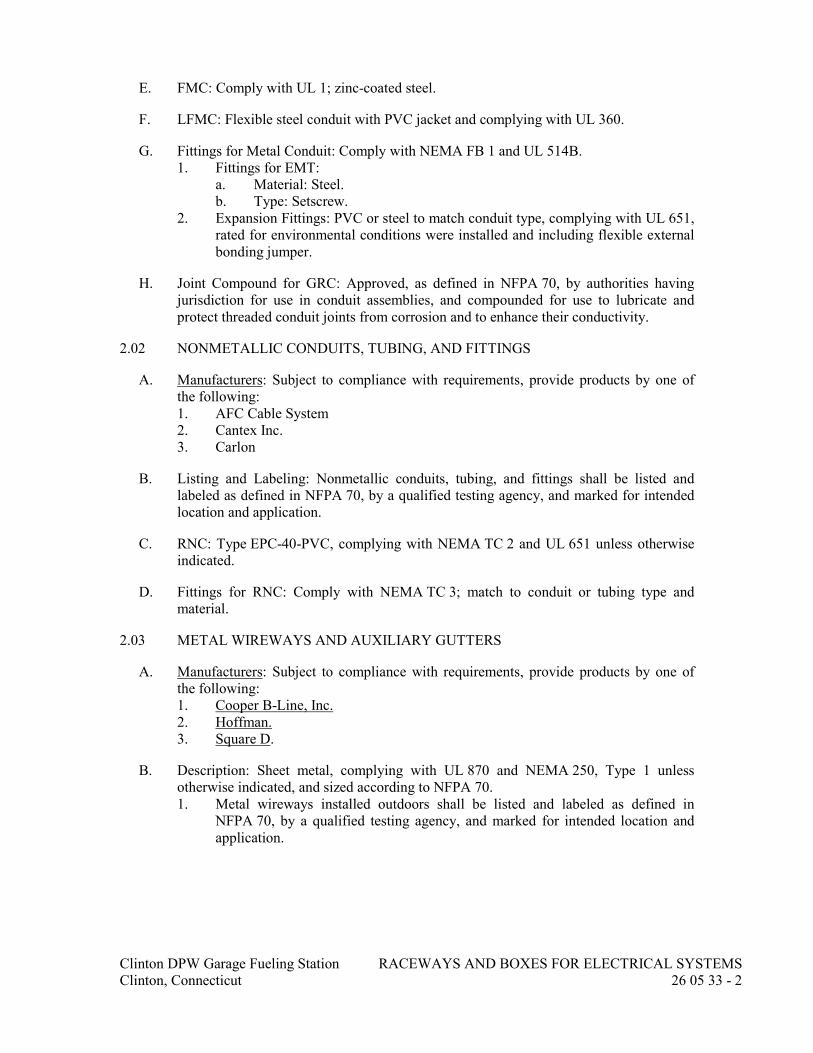
Clinton DPW Garage Fueling Station RACEWAYS AND BOXES FOR ELECTRICAL SYSTEMS
Clinton, Connecticut 26 05 33 - 2
E. FMC: Comply with UL 1; zinc-coated steel.
F. LFMC: Flexible steel conduit with PVC jacket and complying with UL 360.
G. Fittings for Metal Conduit: Comply with NEMA FB 1 and UL 514B.
1. Fittings for EMT:
a. Material: Steel.
b. Type: Setscrew.
2. Expansion Fittings: PVC or steel to match conduit type, complying with UL 651,
rated for environmental conditions were installed and including flexible external
bonding jumper.
H. Joint Compound for GRC: Approved, as defined in NFPA 70, by authorities having
jurisdiction for use in conduit assemblies, and compounded for use to lubricate and
protect threaded conduit joints from corrosion and to enhance their conductivity.
2.02 NONMETALLIC CONDUITS, TUBING, AND FITTINGS
A. Manufacturers: Subject to compliance with requirements, provide products by one of
the following:
1. AFC Cable System
2. Cantex Inc.
3. Carlon
B. Listing and Labeling: Nonmetallic conduits, tubing, and fittings shall be listed and
labeled as defined in NFPA 70, by a qualified testing agency, and marked for intended
location and application.
C. RNC: Type EPC-40-PVC, complying with NEMA TC 2 and UL 651 unless otherwise
indicated.
D. Fittings for RNC: Comply with NEMA TC 3; match to conduit or tubing type and
material.
2.03 METAL WIREWAYS AND AUXILIARY GUTTERS
A. Manufacturers: Subject to compliance with requirements, provide products by one of
the following:
1. Cooper B-Line, Inc.
2. Hoffman.
3. Square D.
B. Description: Sheet metal, complying with UL 870 and NEMA 250, Type 1 unless
otherwise indicated, and sized according to NFPA 70.
1. Metal wireways installed outdoors shall be listed and labeled as defined in
NFPA 70, by a qualified testing agency, and marked for intended location and
application.

Clinton DPW Garage Fueling Station RACEWAYS AND BOXES FOR ELECTRICAL SYSTEMS
Clinton, Connecticut 26 05 33 - 3
C. Fittings and Accessories: Include covers, couplings, offsets, elbows, expansion joints,
adapters, hold-down straps, end caps, and other fittings to match and mate with
wireways as required for complete system.
D. Wireway Covers: Hinged type unless otherwise indicated.
E. Finish: Manufacturer's standard enamel finish.
2.04 BOXES, ENCLOSURES, AND CABINETS
A. Manufacturers: Subject to compliance with requirements, provide products by one of
the following:
1. Cooper Technologies
2. Hubbell Inc.
3. Wiremold
B. General Requirements for Boxes, Enclosures, and Cabinets: Boxes, enclosures, and
cabinets installed in wet locations shall be listed for use in wet locations.
C. Sheet Metal Outlet and Device Boxes: Comply with NEMA OS 1 and UL 514A.
D. Cast-Metal Outlet and Device Boxes: Comply with NEMA FB 1, ferrous alloy,
Type FD, with gasketed cover.
E. Small Sheet Metal Pull and Junction Boxes: NEMA OS 1.
F. Cast-Metal Access, Pull, and Junction Boxes: Comply with NEMA FB 1 and UL 1773,
cast aluminum with gasketed cover.
G. Box extensions used to accommodate new building finishes shall be of same material as
recessed box.
H. Device Box Dimensions: 4 inches square by 2-1/8 inches deep (100 mm square by 60
mm).
I. Gangable boxes are allowed.
PART 3 - EXECUTION
3.01 RACEWAY APPLICATION
A. Outdoors: Apply raceway products as specified below unless otherwise indicated:
1. Exposed Conduit: GRC.
2. Concealed Conduit, Aboveground: GRC.
3. Connection to Vibrating Equipment (Including Transformers and Hydraulic,
Pneumatic, Electric Solenoid, or Motor-Driven Equipment): LFMC.
4. Boxes and Enclosures, Aboveground: NEMA 250, Type 3R.
B. Indoors: Apply raceway products as specified below unless otherwise indicated:
1. Exposed, Not Subject to Physical Damage: EMT.

Clinton DPW Garage Fueling Station RACEWAYS AND BOXES FOR ELECTRICAL SYSTEMS
Clinton, Connecticut 26 05 33 - 4
2. Exposed, Not Subject to Severe Physical Damage: EMT.
3. Exposed and Subject to Severe Physical Damage: GRC. Raceway locations
include the following:
a. Corridors used for traffic of mechanized carts, forklifts, and pallet-
handling units.
b. Mechanical rooms.
4. Concealed in Ceilings and Interior Walls and Partitions: EMT or Metal Clad
Cable/Feeders.
5. Connection to Vibrating Equipment (Including Transformers and Hydraulic,
Pneumatic, Electric Solenoid, or Motor-Driven Equipment): FMC, except use
LFMC in damp or wet locations.
6. Damp or Wet Locations: GRC.
7. Boxes and Enclosures: NEMA 250, Type 1, except use NEMA 250, Type 4
stainless steel in institutional and commercial kitchens and damp or wet
locations.
C. Minimum Raceway Size: 3/4-inch (21-mm) trade size.
D. Raceway Fittings: Compatible with raceways and suitable for use and location.
1. Rigid and Intermediate Steel Conduit: Use threaded rigid steel conduit fittings
unless otherwise indicated. Comply with NEMA FB 2.10.
2. PVC Externally Coated, Rigid Steel Conduits: Use only fittings listed for use
with this type of conduit. Patch and seal all joints, nicks, and scrapes in PVC
coating after installing conduits and fittings. Use sealants recommended by
fitting manufacturer and apply in thickness and number of coats recommended
by manufacturer.
3. EMT: Use setscrew steel fittings. Comply with NEMA FB 2.10.
4. Flexible Conduit: Use only fittings listed for use with flexible conduit. Comply
with NEMA FB 2.20.
E. Install surface raceways only where indicated on Drawings.
F. Do not install nonmetallic conduit where ambient temperature exceeds 120 deg F (49
deg C).
3.02 INSTALLATION
A. Comply with NECA 1 and NECA 101 for installation requirements except where
requirements on Drawings or in this article are stricter. Comply with NECA 102 for
aluminum conduits. Comply with NFPA 70 limitations for types of raceways allowed in
specific occupancies and number of floors.
B. Keep raceways at least 6 inches (150 mm) away from parallel runs of flues and steam or
hot-water pipes. Install horizontal raceway runs above water and steam piping.
C. Complete raceway installation before starting conductor installation.

Clinton DPW Garage Fueling Station RACEWAYS AND BOXES FOR ELECTRICAL SYSTEMS
Clinton, Connecticut 26 05 33 - 5
D. Comply with requirements in Section 260529 "Hangers and Supports for Electrical
Systems" for hangers and supports.
E. Install no more than the equivalent of three 90-degree bends in any conduit run except
for control wiring conduits, for which fewer bends are allowed. Support within 12
inches (300 mm) of changes in direction.
F. Conceal conduit and EMT within finished walls, ceilings, and floors unless otherwise
indicated. Install conduits parallel or perpendicular to building lines.
G. Support conduit within 12 inches (300 mm)of enclosures to which attached.
H. Threaded Conduit Joints, Exposed to Wet, Damp, Corrosive, or Outdoor Conditions:
Apply listed compound to threads of raceway and fittings before making up joints.
Follow compound manufacturer's written instructions.
I. Raceway Terminations at Locations Subject to Moisture or Vibration: Use insulating
bushings to protect conductors including conductors smaller than No. 4 AWG.
J. Terminate threaded conduits into threaded hubs or with locknuts on inside and outside
of boxes or cabinets. Install bushings on conduits up to 1-1/4-inch (35mm) trade size
and insulated throat metal bushings on 1-1/2-inch (41-mm) trade size and larger
conduits terminated with locknuts. Install insulated throat metal grounding bushings on
service conduits.
K. Install raceways square to the enclosure and terminate at enclosures with locknuts.
Install locknuts hand tight plus 1/4 turn more.
L. Do not rely on locknuts to penetrate nonconductive coatings on enclosures. Remove
coatings in the locknut area prior to assembling conduit to enclosure to assure a
continuous ground path.
M. Cut conduit perpendicular to the length. For conduits 2-inch (53-mm) trade size and
larger, use roll cutter or a guide to make cut straight and perpendicular to the length.
N. Install pull wires in empty raceways. Use polypropylene or monofilament plastic line
with not less than 200-lb (90-kg) tensile strength. Leave at least 12 inches (300 mm) of
slack at each end of pull wire. Cap underground raceways designated as spare above
grade alongside raceways in use.
O. Install raceway sealing fittings at accessible locations according to NFPA 70 and fill
them with listed sealing compound. For concealed raceways, install each fitting in a
flush steel box with a blank cover plate having a finish similar to that of adjacent plates
or surfaces. Install raceway sealing fittings according to NFPA 70.
P. Install devices to seal raceway interiors at accessible locations. Locate seals so no
fittings or boxes are between the seal and the following changes of environments. Seal
the interior of all raceways at the following points:
1. Where conduits pass from warm to cold locations, such as boundaries of
refrigerated spaces.
2. Where an underground service raceway enters a building or structure.
3. Where otherwise required by NFPA 70.
Q. Comply with manufacturer's written instructions for solvent welding RNC and fittings.

Clinton DPW Garage Fueling Station RACEWAYS AND BOXES FOR ELECTRICAL SYSTEMS
Clinton, Connecticut 26 05 33 - 6
R. Expansion-Joint Fittings:
1. Install in each run of aboveground RNC that is located where environmental
temperature change may exceed 30 deg F (17 deg C) and that has straight-run
length that exceeds 25 feet (7.6 m). Install in each run of aboveground RMC
conduit that is located where environmental temperature change may exceed 100
deg F (55 deg C) and that has straight-run length that exceeds 100 feet (30 m).
2. Install type and quantity of fittings that accommodate temperature change listed
for each of the following locations:
a. Outdoor Locations Not Exposed to Direct Sunlight: 125 deg F (70 deg C)
temperature change.
b. Outdoor Locations Exposed to Direct Sunlight: 155 deg F (86 deg C)
temperature change.
c. Indoor Spaces Connected with Outdoors without Physical Separation: 125
deg F (70 deg C) temperature change.
d. Attics: 135 deg F (75 deg C) temperature change.
3. Install fitting(s) that provide expansion and contraction for at least 0.00041 inch
per foot of length of straight run per deg F (0.06 mm per meter of length of
straight run per deg C) of temperature change for PVC conduits. Install fitting(s)
that provide expansion and contraction for at least 0.000078 inch per foot of
length of straight run per deg F (0.0115 mm per meter of length of straight run
per deg C) of temperature change for metal conduits.
4. Install expansion fittings at all locations where conduits cross building or
structure expansion joints.
5. Install each expansion-joint fitting with position, mounting, and piston setting
selected according to manufacturer's written instructions for conditions at
specific location at time of installation. Install conduit supports to allow for
expansion movement.
S. Flexible Conduit Connections: Comply with NEMA RV 3. Use a maximum of 72
inches (1830 mm) of flexible conduit for recessed and semirecessed
luminaires, equipment subject to vibration, noise transmission, or movement; and for
transformers and motors.
1. Use LFMC in damp or wet locations subject to severe physical damage.
2. Use LFMC in damp or wet locations not subject to severe physical damage.
T. Mount boxes at heights indicated on Drawings. If mounting heights of boxes are not
individually indicated, give priority to ADA requirements. Install boxes with height
measured to center of box unless otherwise indicated.
U. Recessed Boxes in Masonry Walls: Saw-cut opening for box in center of cell of
masonry block, and install box flush with surface of wall. Prepare block surfaces to
provide a flat surface for a raintight connection between box and cover plate or
supported equipment and box.
V. Horizontally separate boxes mounted on opposite sides of walls so they are not in the
same vertical channel.
W. Locate boxes so that cover or plate will not span different building finishes.
X. Support boxes of three gangs or more from more than one side by spanning two
framing members or mounting on brackets specifically designed for the purpose.

Clinton DPW Garage Fueling Station RACEWAYS AND BOXES FOR ELECTRICAL SYSTEMS
Clinton, Connecticut 26 05 33 - 7
Y. Fasten junction and pull boxes to or support from building structure. Do not support
boxes by conduits.
3.03 SLEEVE AND SLEEVE-SEAL INSTALLATION FOR ELECTRICAL
PENETRATIONS
A. Install sleeves and sleeve seals at penetrations of exterior floor and wall assemblies.
Comply with requirements in Section 260544 "Sleeves and Sleeve Seals for Electrical
Raceways and Cabling."
3.04 FIRESTOPPING
A. Install firestopping at penetrations of fire-rated floor and wall assemblies.
3.05 PROTECTION
A. Protect coatings, finishes, and cabinets from damage and deterioration.
1. Repair damage to galvanized finishes with zinc-rich paint recommended by
manufacturer.
END OF SECTION 26 05 33

Clinton DPW Garage Fueling Station SLEEVES AND SLEEVE SEALS FOR
Clinton, Connecticut ELECTRICAL RACEWAYS AND CABLING
26 05 44 - 1
SECTION 26 05 44
SLEEVES AND SLEEVE SEALS FOR ELECTRICAL RACEWAYS
AND CABLING
PART 1 - GENERAL
1.01 RELATED DOCUMENTS
A. Drawings and general provisions of the Contract, including General and Supplementary
Conditions and Division 01 Specification Sections, apply to this Section.
1.02 SUMMARY
A. Section Includes:
1. Sleeves for raceway and cable penetration of non-fire-rated construction walls
and floors.
2. Sleeve-seal systems.
3. Sleeve-seal fittings.
4. Grout.
5. Silicone sealants.
PART 2 - PRODUCTS
2.01 SLEEVES
A. Wall Sleeves:
1. Cast-Iron Pipe Sleeves: Cast or fabricated "wall pipe," equivalent to ductile-iron
pressure pipe, with plain ends and integral waterstop unless otherwise indicated.
B. Sleeves for Conduits Penetrating Non-Fire-Rated Gypsum Board Assemblies:
Galvanized-steel sheet; 0.0239-inch (0.6-mm) minimum thickness; round tube closed
with welded longitudinal joint, with tabs for screw-fastening the sleeve to the board.
C. PVC-Pipe Sleeves: ASTM D 1785, Schedule 40.
D. Molded-PVC Sleeves: With nailing flange for attaching to wooden forms.
E. Molded-PE or -PP Sleeves: Removable, tapered-cup shaped, and smooth outer surface
with nailing flange for attaching to wooden forms.
F. Sleeves for Rectangular Openings:
1. Material: Galvanized sheet steel.
2. Minimum Metal Thickness:
a. For sleeve cross-section rectangle perimeter less than 50 inches (1270 mm)
and with no side larger than 16 inches (400 mm), thickness shall be 0.052
inch (1.3 mm).

Clinton DPW Garage Fueling Station SLEEVES AND SLEEVE SEALS FOR
Clinton, Connecticut ELECTRICAL RACEWAYS AND CABLING
26 05 44 - 2
b. For sleeve cross-section rectangle perimeter 50 inches (1270 mm) or more
and one or more sides larger than 16 inches (400 mm), thickness shall be
0.138 inch (3.5 mm).
2.02 SLEEVE-SEAL SYSTEMS
A. Description: Modular sealing device, designed for field assembly, to fill annular space
between sleeve and raceway or cable.
1. Sealing Elements: EPDM rubber interlocking links shaped to fit surface of pipe.
Include type and number required for pipe material and size of pipe.
2. Pressure Plates: Carbon steel.
3. Connecting Bolts and Nuts: Carbon steel, with corrosion-resistant coating of
length required to secure pressure plates to sealing elements.
2.03 SLEEVE-SEAL FITTINGS
A. Description: Manufactured plastic, sleeve-type, waterstop assembly made for
embedding in concrete slab or wall. Unit shall have plastic or rubber waterstop collar
with center opening to match piping OD.
2.04 GROUT
A. Description: Nonshrink; recommended for interior and exterior sealing openings in non-
fire-rated walls or floors.
B. Standard: ASTM C 1107/C 1107M, Grade B, post-hardening and volume-adjusting,
dry, hydraulic-cement grout.
C. Design Mix: 5000-psi (34.5-MPa), 28-day compressive strength.
D. Packaging: Premixed and factory packaged.
2.05 SILICONE SEALANTS
A. Silicone Sealants: Single-component, silicone-based, neutral-curing elastomeric
sealants of grade indicated below.
1. Grade: Pourable (self-leveling) formulation for openings in floors and other
horizontal surfaces that are not fire rated.
B. Silicone Foams: Multicomponent, silicone-based liquid elastomers that, when mixed,
expand and cure in place to produce a flexible, nonshrinking foam.
PART 3 - EXECUTION
3.01 SLEEVE INSTALLATION FOR NON-FIRE-RATED ELECTRICAL
PENETRATIONS
A. Comply with NECA 1.
B. Comply with NEMA VE 2 for cable tray and cable penetrations.

Clinton DPW Garage Fueling Station SLEEVES AND SLEEVE SEALS FOR
Clinton, Connecticut ELECTRICAL RACEWAYS AND CABLING
26 05 44 - 3
C. Sleeves for Conduits Penetrating Above-Grade Non-Fire-Rated Concrete and Masonry-
Unit Floors and Walls:
1. Interior Penetrations of Non-Fire-Rated Walls and Floors:
a. Seal annular space between sleeve and raceway or cable, using joint
sealant appropriate for size, depth, and location of joint. Comply with
requirements in Section 079200 "Joint Sealants."
b. Seal space outside of sleeves with mortar or grout. Pack sealing material
solidly between sleeve and wall so no voids remain. Tool exposed surfaces
smooth; protect material while curing.
2. Use pipe sleeves unless penetration arrangement requires rectangular sleeved
opening.
3. Size pipe sleeves to provide 1/4-inch (6.4-mm) annular clear space between
sleeve and raceway or cable unless sleeve seal is to be installed or unless seismic
criteria require different clearance.
4. Install sleeves for wall penetrations unless core-drilled holes or formed openings
are used. Install sleeves during erection of walls. Cut sleeves to length for
mounting flush with both surfaces of walls. Deburr after cutting.
5. Install sleeves for floor penetrations. Extend sleeves installed in floors 2 inches
(50 mm) above finished floor level. Install sleeves during erection of floors.
D. Sleeves for Conduits Penetrating Non-Fire-Rated Gypsum Board Assemblies:
1. Use circular metal sleeves unless penetration arrangement requires rectangular
sleeved opening.
2. Seal space outside of sleeves with approved joint compound for gypsum board
assemblies.
E. Roof-Penetration Sleeves: Seal penetration of individual raceways and cables with
flexible boot-type flashing units applied in coordination with roofing work.
F. Aboveground, Exterior-Wall Penetrations: Seal penetrations using steel pipe sleeves
and mechanical sleeve seals. Select sleeve size to allow for 1-inch (25-mm) annular
clear space between pipe and sleeve for installing mechanical sleeve seals.
G. Underground, Exterior-Wall and Floor Penetrations: Install cast-iron pipe sleeves. Size
sleeves to allow for 1-inch (25-mm) annular clear space between raceway or cable and
sleeve for installing sleeve-seal system.
3.02 SLEEVE-SEAL-SYSTEM INSTALLATION
A. Install sleeve-seal systems in sleeves in exterior concrete walls and slabs-on-grade at
raceway entries into building.
B. Install type and number of sealing elements recommended by manufacturer for raceway
or cable material and size. Position raceway or cable in center of sleeve. Assemble
mechanical sleeve seals and install in annular space between raceway or cable and
sleeve. Tighten bolts against pressure plates that cause sealing elements to expand and
make watertight seal.
3.03 SLEEVE-SEAL-FITTING INSTALLATION
A. Install sleeve-seal fittings in new walls and slabs as they are constructed.

Clinton DPW Garage Fueling Station SLEEVES AND SLEEVE SEALS FOR
Clinton, Connecticut ELECTRICAL RACEWAYS AND CABLING
26 05 44 - 4
B. Assemble fitting components of length to be flush with both surfaces of concrete slabs
and walls. Position waterstop flange to be centered in concrete slab or wall.
C. Secure nailing flanges to concrete forms.
D. Using grout, seal the space around outside of sleeve-seal fittings.
END OF SECTION 26 05 44

Clinton DPW Garage Fueling Station IDENTIFICATION FOR ELECTRICAL SYSTEMS
Clinton, Connecticut 26 05 53 - 1
SECTION 26 05 53
IDENTIFICATION FOR ELECTRICAL SYSTEMS
PART 1 - GENERAL
1.01 RELATED DOCUMENTS
A. Drawings and general provisions of the Contract, including General and Supplementary
Conditions and Division 01 Specification Sections, apply to this Section.
B. Contractor is responsible for Specification Section 019113 – General Commissioning
Requirements as it pertains to their work, and shall participate in and perform
commissioning team activities.
1.02 SUMMARY
A. Section Includes:
1. Identification for raceways.
2. Identification of power and control cables.
3. Identification for conductors.
4. Underground-line warning tape.
5. Warning labels and signs.
6. Instruction signs.
7. Equipment identification labels, including arc-flash warning labels.
8. Miscellaneous identification products.
1.03 ACTION SUBMITTALS
A. Product Data: For each type of product.
1. Include construction details, material descriptions, dimensions of individual
components and profiles, and finishes for electrical identification products.
B. Identification Schedule: For each piece of electrical equipment and electrical system
components to be an index of nomenclature for electrical equipment and system
components used in identification signs and labels. Use same designations indicated on
Drawings.
C. Delegated-Design Submittal: For arc-flash hazard study.
PART 2 - PRODUCTS
2.01 PERFORMANCE REQUIREMENTS
A. Comply with NFPA 70.
B. Comply with 29 CFR 1910.144 and 29 CFR 1910.145.
C. Comply with ANSI Z535.4 for safety signs and labels.

Clinton DPW Garage Fueling Station IDENTIFICATION FOR ELECTRICAL SYSTEMS
Clinton, Connecticut 26 05 53 - 2
D. Adhesive-attached labeling materials, including label stocks, laminating adhesives, and
inks used by label printers, shall comply with UL 969.
E. Thermal Movements: Allow for thermal movements from ambient and surface
temperature changes.
1. Temperature Change: 120 deg F (67 deg C) ambient; 180 deg F (100 deg C),
material surfaces.
2.02 COLOR AND LEGEND REQUIREMENTS
A. Raceways and Cables Carrying Circuits at 600 V or Less:
1. Black letters on an orange field.
2. Legend: Indicate voltage and system or service type.
B. Warning labels and signs shall include, but are not limited to, the following legends:
1. Multiple Power Source Warning: "DANGER - ELECTRICAL SHOCK
HAZARD - EQUIPMENT HAS MULTIPLE POWER SOURCES."
2.03 LABELS
A. Vinyl Labels for Raceways Carrying Circuits at 600 V or Less: Preprinted, flexible
labels laminated with a clear, weather- and chemical-resistant coating and matching
wraparound clear adhesive tape for securing label ends.
1. Manufacturers: Subject to compliance with requirements, provide products by
one of the following:
a. Brady Corporation.
b. emedco.
c. Panduit Corp.
B. Snap-Around Labels for Raceways and Cables Carrying Circuits at 600 V or Less: Slit,
pretensioned, flexible, preprinted, color-coded acrylic sleeves, with diameters sized to
suit diameters of raceways they identify, and that stay in place by gripping action.
1. Manufacturers: Subject to compliance with requirements, provide products by
one of the following:
a. Brady Corporation.
b. emedco.
c. Panduit Corp.
C. Self-Adhesive Labels:
1. Manufacturers: Subject to compliance with requirements, provide products by
one of the following:
a. Brady Corporation.
b. emedco.
c. Panduit Corp.
2. Preprinted, 3-mil- (0.08-mm-) thick, polyester flexible label with acrylic
pressure-sensitive adhesive.
a. Self-Lamination: Clear; UV-, weather- and chemical-resistant; self-
laminating, protective shield over the legend. Labels sized to fit the cable
raceway diameter, such that the clear shield overlaps the entire printed
legend.
3. Polyester, thermal, transfer-printed, 3-mil- (0.08-mm-) thick, multicolor,
weather- and UV-resistant, pressure-sensitive adhesive labels, configured for

Clinton DPW Garage Fueling Station IDENTIFICATION FOR ELECTRICAL SYSTEMS
Clinton, Connecticut 26 05 53 - 3
display on front cover, door, or other access to equipment unless otherwise
indicated.
a. Nominal Size: 3.5-by-5-inch (76-by-127-mm).
4. Marker for Tags: Machine-printed, permanent, waterproof, black ink
recommended by printer manufacturer.
2.04 BANDS AND TUBES:
A. Snap-Around, Color-Coding Bands for Raceways and Cables: Slit, pretensioned,
flexible, solid-colored acrylic sleeves, 2 inches (50 mm) long, with diameters sized to
suit diameters of raceways or cables they identify, and that stay in place by gripping
action.
1. Manufacturers: Subject to compliance with requirements, provide products by
one of the following:
a. Brady Corporation.
b. emedco.
c. Panduit Corp.
B. Heat-Shrink Preprinted Tubes: Flame-retardant polyolefin tubes with machine-printed
identification labels, sized to suit diameters of and shrunk to fit firmly around cables
they identify. Full shrink recovery occurs at a maximum of 200 deg F (93 deg C).
Comply with UL 224.
1. Manufacturers: Subject to compliance with requirements, provide products by
one of the following:
a. Brady Corporation.
b. emedco.
c. Panduit Corp.
2.05 TAPES AND STENCILS:
A. Marker Tapes: Vinyl or vinyl-cloth, self-adhesive wraparound type, with circuit
identification legend machine printed by thermal transfer or equivalent process.
1. Manufacturers: Subject to compliance with requirements, provide products by
one of the following:
a. Brady Corporation.
b. emedco.
c. Panduit Corp.
B. Self-Adhesive Vinyl Tape: Colored, heavy duty, waterproof, fade resistant; not less
than 3 mils (0.08 mm) thick by 1 to 2 inches (25 to 50 mm) wide; compounded for
outdoor use.
1. Manufacturers: Subject to compliance with requirements, provide products by
one of the following:
a. Brady Corporation.
b. emedco.
c. Marking Services, Inc.
C. Tape and Stencil for Raceways Carrying Circuits 600 V or Less: 4-inch- (100-mm-)
wide black stripes on 10-inch (250-mm) centers placed diagonally over orange
background that extends full length of raceway or duct and is 12 inches (300 mm) wide.
Stop stripes at legends.
1. Manufacturers: Subject to compliance with requirements, provide products by
one of the following:

Clinton DPW Garage Fueling Station IDENTIFICATION FOR ELECTRICAL SYSTEMS
Clinton, Connecticut 26 05 53 - 4
a. LEM Products Inc.
b. Marking Services, Inc.
c. Seton Identification Products.
D. Floor Marking Tape: 2-inch- (50-mm-) wide, 5-mil (0.125-mm) pressure-sensitive vinyl
tape, with black and white stripes and clear vinyl overlay.
1. Manufacturers: Subject to compliance with requirements, provide products by
one of the following:
a. Carlton Industries, LP.
b. Seton Identification Products.
E. Underground-Line Warning Tape
1. Manufacturers: Subject to compliance with requirements, provide products by
one of the following:
a. Brady Corporation.
b. Ideal Industries, Inc.
c. Marking Services, Inc.
2. Tape:
a. Recommended by manufacturer for the method of installation and suitable
to identify and locate underground electrical and communications utility
lines.
b. Printing on tape shall be permanent and shall not be damaged by burial
operations.
c. Tape material and ink shall be chemically inert and not subject to
degradation when exposed to acids, alkalis, and other destructive
substances commonly found in soils.
3. Color and Printing:
a. Comply with ANSI Z535.1, ANSI Z535.2, ANSI Z535.3, ANSI Z535.4,
and ANSI Z535.5.
b. Inscriptions for Red-Colored Tapes: "ELECTRIC LINE, HIGH
VOLTAGE".
c. Inscriptions for Orange-Colored Tapes: "TELEPHONE CABLE, CATV
CABLE, COMMUNICATIONS CABLE, OPTICAL FIBER CABLE".
F. Stenciled Legend: In nonfading, waterproof, black ink or paint. Minimum letter height
shall be 1 inch (25 mm).
2.06 TAGS
A. Metal Tags: Brass or aluminum, 2 by 2 by 0.05 inch (50 by 50 by 1.3 mm), with
stamped legend, punched for use with self-locking cable tie fastener.
1. Manufacturers: Subject to compliance with requirements, provide products by
one of the following:
a. Brady Corporation.
b. emedco.
c. Marking Services, Inc.
B. Nonmetallic Preprinted Tags: Polyethylene tags, 0.023 inch (0.58 mm) thick, color-
coded for phase and voltage level, with factory screened printed permanent
designations; punched for use with self-locking cable tie fastener.
1. Manufacturers: Subject to compliance with requirements, provide products by
one of the following:
a. Brady Corporation.

Clinton DPW Garage Fueling Station IDENTIFICATION FOR ELECTRICAL SYSTEMS
Clinton, Connecticut 26 05 53 - 5
b. emedco.
c. Marking Services, Inc.
2.07 SIGNS
A. Baked-Enamel Signs:
1. Preprinted aluminum signs, punched or drilled for fasteners, with colors, legend,
and size required for application.
2. 1/4-inch (6.4-mm) grommets in corners for mounting.
3. Nominal Size: 7 by 10 inches (180 by 250 mm).
4. Manufacturers: Subject to compliance with requirements, provide products by
one of the following:
a. Carlton Industries, LP.
b. emedco.
c. Marking Services, Inc.
B. Metal-Backed Butyrate Signs:
1. Weather-resistant, nonfading, preprinted, cellulose-acetate butyrate signs, with
0.0396-inch (1-mm) galvanized-steel backing and with colors, legend, and size
required for application.
2. 1/4-inch (6.4-mm) grommets in corners for mounting.
3. Nominal Size: 10 by 14 inches (250 by 360 mm).
4. Manufacturers: Subject to compliance with requirements, provide products by
one of the following:
a. Brady Corporation.
b. emedco.
c. Marking Services, Inc.
C. Laminated Acrylic or Melamine Plastic Signs:
1. Engraved legend.
2. Thickness:
a. For signs up to 20 sq. inches (129 sq. cm), minimum 1/16-inch- (1.6-mm-
).
b. For signs larger than 20 sq. inches (129 sq. cm), 1/8 inch (3.2 mm) thick.
c. Punched or drilled for mechanical fasteners.
d. Framed with mitered acrylic molding and arranged for attachment at
applicable equipment.
e. Manufacturers: Subject to compliance with requirements, provide products
by one of the following:
1) Brady Corporation.
2) emedco.
3) Marking Services, Inc.
2.08 CABLE TIES
A. Manufacturers: Subject to compliance with requirements, provide products by one of
the following:
1. Ideal Industries, Inc.
2. Marking Services, Inc.
3. Panduit Corp.
B. General-Purpose Cable Ties: Fungus inert, self-extinguishing, one piece, self-locking,
Type 6/6 nylon.
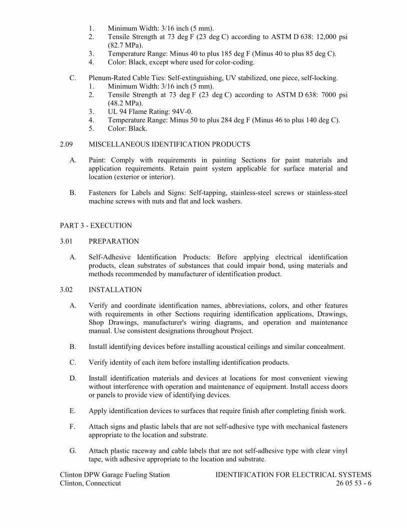
Clinton DPW Garage Fueling Station IDENTIFICATION FOR ELECTRICAL SYSTEMS
Clinton, Connecticut 26 05 53 - 6
1. Minimum Width: 3/16 inch (5 mm).
2. Tensile Strength at 73 deg F (23 deg C) according to ASTM D 638: 12,000 psi
(82.7 MPa).
3. Temperature Range: Minus 40 to plus 185 deg F (Minus 40 to plus 85 deg C).
4. Color: Black, except where used for color-coding.
C. Plenum-Rated Cable Ties: Self-extinguishing, UV stabilized, one piece, self-locking.
1. Minimum Width: 3/16 inch (5 mm).
2. Tensile Strength at 73 deg F (23 deg C) according to ASTM D 638: 7000 psi
(48.2 MPa).
3. UL 94 Flame Rating: 94V-0.
4. Temperature Range: Minus 50 to plus 284 deg F (Minus 46 to plus 140 deg C).
5. Color: Black.
2.09 MISCELLANEOUS IDENTIFICATION PRODUCTS
A. Paint: Comply with requirements in painting Sections for paint materials and
application requirements. Retain paint system applicable for surface material and
location (exterior or interior).
B. Fasteners for Labels and Signs: Self-tapping, stainless-steel screws or stainless-steel
machine screws with nuts and flat and lock washers.
PART 3 - EXECUTION
3.01 PREPARATION
A. Self-Adhesive Identification Products: Before applying electrical identification
products, clean substrates of substances that could impair bond, using materials and
methods recommended by manufacturer of identification product.
3.02 INSTALLATION
A. Verify and coordinate identification names, abbreviations, colors, and other features
with requirements in other Sections requiring identification applications, Drawings,
Shop Drawings, manufacturer's wiring diagrams, and operation and maintenance
manual. Use consistent designations throughout Project.
B. Install identifying devices before installing acoustical ceilings and similar concealment.
C. Verify identity of each item before installing identification products.
D. Install identification materials and devices at locations for most convenient viewing
without interference with operation and maintenance of equipment. Install access doors
or panels to provide view of identifying devices.
E. Apply identification devices to surfaces that require finish after completing finish work.
F. Attach signs and plastic labels that are not self-adhesive type with mechanical fasteners
appropriate to the location and substrate.
G. Attach plastic raceway and cable labels that are not self-adhesive type with clear vinyl
tape, with adhesive appropriate to the location and substrate.

Clinton DPW Garage Fueling Station IDENTIFICATION FOR ELECTRICAL SYSTEMS
Clinton, Connecticut 26 05 53 - 7
H. Cable Ties: For attaching tags. Use general-purpose type, except as listed below:
1. Outdoors: UV-stabilized nylon.
2. In Spaces Handling Environmental Air: Plenum rated.
I. Painted Identification: Comply with requirements in painting Sections for surface
preparation and paint application.
J. Aluminum Wraparound Marker Labels and Metal Tags: Secure tight to surface of
conductor or cable at a location with high visibility and accessibility.
K. System Identification Color-Coding Bands for Raceways and Cables: Each color-
coding band shall completely encircle cable or conduit. Place adjacent bands of two-
color markings in contact, side by side. Locate bands at changes in direction, at
penetrations of walls and floors, at 50-foot (15-m) maximum intervals in straight runs,
and at 25-foot (7.6-m) maximum intervals in congested areas.
L. During backfilling of trenches, install continuous underground-line warning tape
directly above cable or raceway at 6 to 8 inches (150 to 200 mm) below finished grade.
Use multiple tapes where width of multiple lines installed in a common trench or
concrete envelope exceeds 16 inches (400 mm) overall.
3.03 IDENTIFICATION SCHEDULE
A. Accessible Raceways and Metal-Clad Cables, 600 V or Less, for Service, Feeder, and
Branch Circuits, More Than 30 A and 120 V to Ground: Identify with self-adhesive
vinyl label. Install labels at 30-foot (10-m) maximum intervals.
B. Accessible Raceways and Cables within Buildings: Identify the covers of each junction
and pull box of the following systems with self-adhesive vinyl labels containing the
wiring system legend and system voltage. System legends shall be as follows:
1. "POWER."
C. Power-Circuit Conductor Identification, 600 V or Less: For conductors in vaults, pull
and junction boxes, manholes, and handholes, use color-coding conductor tape to
identify the phase.
1. Color-Coding for Phase-Identification, 600 V or Less: Use colors listed below for
ungrounded service, feeder, and branch-circuit conductors.
a. Color shall be factory applied.
b. Colors for 240/120-V Circuits:
1) Phase A: Black.
2) Phase B: Red.
3) Neutral: White.
c. Field-Applied, Color-Coding Conductor Tape: Apply in half-lapped turns
for a minimum distance of 6 inches (150 mm) from terminal points and in
boxes where splices or taps are made. Apply last two turns of tape with no
tension to prevent possible unwinding. Locate bands to avoid obscuring
factory cable markings.
D. Install instructional sign, including the color code for grounded and ungrounded
conductors using adhesive-film-type labels.
E. Control-Circuit Conductor Identification: For conductors and cables in pull and junction
boxes, manholes, and handholes, use self-adhesive, self-laminating polyester labels
with the conductor or cable designation, origin, and destination.

Clinton DPW Garage Fueling Station IDENTIFICATION FOR ELECTRICAL SYSTEMS
Clinton, Connecticut 26 05 53 - 8
F. Control-Circuit Conductor Termination Identification: For identification at
terminations, provide elf-adhesive, self-laminating polyester labels with the conductor
designation.
G. Conductors to Be Extended in the Future: Attach write on tags to conductors and list
source.
H. Auxiliary Electrical Systems Conductor Identification: Identify field-installed alarm,
control, and signal connections.
1. Identify conductors, cables, and terminals in enclosures and at junctions,
terminals, and pull points. Identify by system and circuit designation.
2. Use system of marker-tape designations that is uniform and consistent with
system used by manufacturer for factory-installed connections.
3. Coordinate identification with Project Drawings, manufacturer's wiring diagrams,
and operation and maintenance manual.
I. Locations of Underground Lines: Identify with underground-line warning tape for
power, lighting, communication, and control wiring and optical-fiber cable.
1. Limit use of underground-line warning tape to direct-buried cables.
2. Install underground-line warning tape for direct-buried cables and cables in
raceways.
J. Workspace Indication: Install floor marking tape to show working clearances in the
direction of access to live parts. Workspace shall comply with NFPA 70 and
29 CFR 1926.403 unless otherwise indicated. Do not install at flush-mounted
panelboards and similar equipment in finished spaces.
K. Warning Labels for Indoor Cabinets, Boxes, and Enclosures for Power and Lighting:
Self-adhesive warning labels.
1. Comply with 29 CFR 1910.145.
2. Identify system voltage with black letters on an orange background.
3. Apply to exterior of door, cover, or other access.
4. For equipment with multiple power or control sources, apply to door or cover of
equipment, including, but not limited to, the following:
a. Power-transfer switches.
b. Controls with external control power connections.
L. Operating Instruction Signs: Install instruction signs to facilitate proper operation and
maintenance of electrical systems and items to which they connect. Install instruction
signs with approved legend where instructions are needed for system or equipment
operation.
M. Emergency Operating Instruction Signs: Install instruction signs with white legend on a
red background with minimum 3/8-inch- (10-mm-) high letters for emergency
instructions at equipment used for power transfer.
N. Equipment Identification Labels: On each unit of equipment, install unique designation
label that is consistent with wiring diagrams, schedules, and operation and maintenance
manual. Apply labels to disconnect switches and protection equipment, central or
master units, control panels, control stations, terminal cabinets, and racks of each
system. Systems include power, lighting, control, communication, signal, monitoring,
and alarm unless equipment is provided with its own identification.
1. Labeling Instructions:

Clinton DPW Garage Fueling Station IDENTIFICATION FOR ELECTRICAL SYSTEMS
Clinton, Connecticut 26 05 53 - 9
a. Indoor Equipment: Self-adhesive, engraved, laminated acrylic or
melamine plastic label. Unless otherwise indicated, provide a single line of
text with 1/2-inch- (13-mm-) high letters on 1-1/2-inch- (38-mm-) high
label; where two lines of text are required, use labels 2 inches (50 mm)
high.
b. Outdoor Equipment: Engraved, laminated acrylic or melamine label.
c. Elevated Components: Increase sizes of labels and letters to those
appropriate for viewing from the floor.
d. Unless labels are provided with self-adhesive means of attachment, fasten
them with appropriate mechanical fasteners that do not change the NEMA
or NRTL rating of the enclosure.
2. Equipment To Be Labeled:
a. Panelboards: Typewritten directory of circuits in the location provided by
panelboard manufacturer. Panelboard identification shall be in the form of
a self-adhesive, engraved laminated acrylic or melamine label.
b. Enclosures and electrical cabinets.
c. Access doors and panels for concealed electrical items.
d. Switchboards.
e. Transformers: Label that includes tag designation shown on Drawings for
the transformer, feeder, and panelboards or equipment supplied by the
secondary.
f. Emergency system boxes and enclosures.
g. Enclosed switches.
h. Enclosed circuit breakers.
i. Enclosed controllers.
j. Variable-speed controllers.
k. Push-button stations.
l. Power-transfer equipment.
m. Contactors.
n. Remote-controlled switches, dimmer modules, and control devices.
o. Battery-inverter units.
p. Power-generating units.
END OF SECTION 26 05 53

Clinton DPW Garage Fueling Station PANELBOARDS
Clinton, Connecticut 26 24 16 - 1
SECTION 26 24 16
PANELBOARDS
PART 1 - GENERAL
1.1 RELATED DOCUMENTS
A. Drawings and general provisions of the Contract, including General and Supplementary
Conditions and Division 01 Specification Sections, apply to this Section.
1.2 SUMMARY
A. Section Includes:
1. Distribution panelboards.
2. Lighting and appliance branch-circuit panelboards.
1.3 DEFINITIONS
A. ATS: Acceptance testing specification.
B. GFCI: Ground-fault circuit interrupter.
C. GFEP: Ground-fault equipment protection.
D. HID: High-intensity discharge.
E. MCCB: Molded-case circuit breaker.
F. VPR: Voltage protection rating.
1.4 ACTION SUBMITTALS
A. Product Data: For each type of panelboard.
1. Include materials, switching and overcurrent protective devices, SPDs, accessories, and
components indicated.
2. Include dimensions and manufacturers' technical data on features, performance, electrical
characteristics, ratings, and finishes.
B. Shop Drawings: For each panelboard and related equipment.
1. Include dimensioned plans, elevations, sections, and details.
2. Show tabulations of installed devices with nameplates, conductor termination sizes,
equipment features, and ratings.

Clinton DPW Garage Fueling Station PANELBOARDS
Clinton, Connecticut 26 24 16 - 2
3. Detail enclosure types including mounting and anchorage, environmental protection,
knockouts, corner treatments, covers and doors, gaskets, hinges, and locks.
4. Detail bus configuration, current, and voltage ratings.
5. Short-circuit current rating of panelboards and overcurrent protective devices.
6. Include evidence of NRTL listing for SPD as installed in panelboard.
7. Detail features, characteristics, ratings, and factory settings of individual overcurrent
protective devices and auxiliary components.
8. Include wiring diagrams for power, signal, and control wiring.
9. Key interlock scheme drawing and sequence of operations.
10. Include time-current coordination curves for each type and rating of overcurrent
protective device included in panelboards. Submit on translucent log-log graft paper;
include selectable ranges for each type of overcurrent protective device. Include an
Internet link for electronic access to downloadable PDF of the coordination curves.
1.5 INFORMATIONAL SUBMITTALS
A. Qualification Data: For testing agency.
B. Panelboard Schedules: For installation in panelboards. Submit final versions after load
balancing.
1.6 CLOSEOUT SUBMITTALS
A. Operation and Maintenance Data: For panelboards and components to include in emergency,
operation, and maintenance manuals. In addition to items specified in Section 017823
"Operation and Maintenance Data," include the following:
1. Manufacturer's written instructions for testing and adjusting overcurrent protective
devices.
2. Time-current curves, including selectable ranges for each type of overcurrent protective
device that allows adjustments.
1.7 QUALITY ASSURANCE
A. Manufacturer Qualifications: ISO 9001 or 9002 certified.
1.8 DELIVERY, STORAGE, AND HANDLING
A. Remove loose packing and flammable materials from inside panelboards; install temporary
electric heating (250 W per panelboard) to prevent condensation.
B. Handle and prepare panelboards for installation according to NEMA PB 1.
1.9 FIELD CONDITIONS
A. Environmental Limitations:
1. Do not deliver or install panelboards until spaces are enclosed and weathertight, wet work
in spaces is complete and dry, work above panelboards is complete, and temporary

Clinton DPW Garage Fueling Station PANELBOARDS
Clinton, Connecticut 26 24 16 - 3
HVAC system is operating and maintaining ambient temperature and humidity conditions
at occupancy levels during the remainder of the construction period.
2. Rate equipment for continuous operation under the following conditions unless otherwise
indicated:
B. Interruption of Existing Electric Service: Do not interrupt electric service to facilities occupied
by Owner or others unless permitted under the following conditions and then only after
arranging to provide temporary electric service according to requirements indicated:
1. Notify Architect no fewer than two days in advance of proposed interruption of electric
service.
2. Do not proceed with interruption of electric service without Architect's written
permission.
3. Comply with NFPA 70E.
1.10 WARRANTY
A. Manufacturer's Warranty: Manufacturer agrees to repair or replace panelboards that fail in
materials or workmanship within specified warranty period.
1. Panelboard Warranty Period: 18 months from date of Substantial Completion.
B. Special Warranty: Manufacturer's standard form in which manufacturer agrees to repair or
replace SPD that fails in materials or workmanship within specified warranty period.
1. SPD Warranty Period: Five years from date of Substantial Completion.
PART 2 - PRODUCTS
2.1 PANELBOARDS AND LOAD CENTERS COMMON REQUIREMENTS
A. Fabricate and test panelboards according to IEEE 344 to withstand seismic forces defined in
Section 260548.16 "Seismic Controls for Electrical Systems."
B. Product Selection for Restricted Space: Drawings indicate maximum dimensions for
panelboards including clearances between panelboards and adjacent surfaces and other items.
Comply with indicated maximum dimensions.
C. Electrical Components, Devices, and Accessories: Listed and labeled as defined in NFPA 70, by
a qualified testing agency, and marked for intended location and application.
D. Comply with NEMA PB 1.
E. Comply with NFPA 70.
F. Enclosures: Flush and Surface-mounted, dead-front cabinets.
1. Rated for environmental conditions at installed location.
a. Indoor Dry and Clean Locations: NEMA 250, Type 1.
b. Outdoor Locations: NEMA 250, Type 3R.

Clinton DPW Garage Fueling Station PANELBOARDS
Clinton, Connecticut 26 24 16 - 4
c. Kitchen Areas: NEMA 250, Type 4X, stainless steel.
d. Other Wet or Damp Indoor Locations: NEMA 250, Type 4.
2. Height: 84 inches (2.13 m) maximum.
3. Hinged Front Cover: Entire front trim hinged to box and with standard door within
hinged trim cover. Trims shall cover all live parts and shall have no exposed hardware.
4. Skirt for Surface-Mounted Panelboards: Same gage and finish as panelboard front with
flanges for attachment to panelboard, wall, and ceiling or floor.
5. Finishes:
a. Panels and Trim: Steel, factory finished immediately after cleaning and pretreating
with manufacturer's standard two-coat, baked-on finish consisting of prime coat
and thermosetting topcoat.
b. Back Boxes: Galvanized steel.
G. Incoming Mains:
1. Location: Top or Bottom.
2. Main Breaker: Main lug interiors up to 400 amperes shall be field convertible to main
breaker.
H. Phase, Neutral, and Ground Buses:
1. Material: Hard-drawn copper, 98 percent conductivity.
a. Bus shall be fully rated the entire length.
2. Interiors shall be factory assembled into a unit. Replacing switching and protective
devices shall not disturb adjacent units or require removing the main bus connectors.
3. Equipment Ground Bus: Adequate for feeder and branch-circuit equipment grounding
conductors; bonded to box.
4. Full-Sized Neutral: Equipped with full-capacity bonding strap for service entrance
applications. Mount electrically isolated from enclosure. Do not mount neutral bus in
gutter.
I. Conductor Connectors: Suitable for use with conductor material and sizes.
1. Material: Hard-drawn copper, 98 percent conductivity.
2. Terminations shall allow use of 75 deg C rated conductors without derating.
3. Size: Lugs suitable for indicated conductor sizes, with additional gutter space, if required,
for larger conductors.
4. Main and Neutral Lugs: Mechanical type, with a lug on the neutral bar for each pole in
the panelboard.
5. Ground Lugs and Bus-Configured Terminators: Mechanical type, with a lug on the bar
for each pole in the panelboard.
6. Feed-Through Lugs: Mechanical type, suitable for use with conductor material. Locate at
opposite end of bus from incoming lugs or main device.
J. Future Devices: Panelboards or load centers shall have mounting brackets, bus connections,
filler plates, and necessary appurtenances required for future installation of devices.
1. Percentage of Future Space Capacity: Ten percent.

Clinton DPW Garage Fueling Station PANELBOARDS
Clinton, Connecticut 26 24 16 - 5
K. Panelboard Short-Circuit Current Rating: Fully rated to interrupt symmetrical short-circuit
current available at terminals. Assembly listed by an NRTL for 100 percent interrupting
capacity.
1. Panelboards and overcurrent protective devices rated 240 V or less shall have short-
circuit ratings as shown on Drawings, but not less than 10,000 A rms symmetrical.
2.2 PERFORMANCE REQUIREMENTS
A. Seismic Performance: Panelboards shall withstand the effects of earthquake motions determined
according to ASCE/SEI 7.
2.3 POWER PANELBOARDS
A. Manufacturers: Subject to compliance with requirements, available manufacturers offering
products that may be incorporated into the Work include, but are not limited to the following:
1. Eaton.
2. General Electric Company; GE Energy Management - Electrical Distribution.
3. Siemens Energy.
4. Square D; by Schneider Electric.
B. Panelboards: NEMA PB 1, distribution type.
C. Doors: Secured with vault-type latch with tumbler lock; keyed alike.
1. For doors more than 36 inches (914 mm) high, provide two latches, keyed alike.
D. Mains: Circuit breaker.
E. Branch Overcurrent Protective Devices for Circuit-Breaker Frame Sizes 125 A and Smaller:
Bolt-on circuit breakers.
2.4 LIGHTING AND APPLIANCE BRANCH-CIRCUIT PANELBOARDS
A. Manufacturers: Subject to compliance with requirements, provide products by one of the
following:
1. Eaton.
2. General Electric Company; GE Energy Management - Electrical Distribution.
3. Siemens Energy.
4. Square D; by Schneider Electric.
B. Panelboards: NEMA PB 1, lighting and appliance branch-circuit type.
C. Mains: Circuit breaker or lugs only.
D. Branch Overcurrent Protective Devices: Bolt-on circuit breakers, replaceable without
disturbing adjacent units.

Clinton DPW Garage Fueling Station PANELBOARDS
Clinton, Connecticut 26 24 16 - 6
E. Doors: Door-in-door construction with concealed hinges; secured with multipoint latch with
tumbler lock; keyed alike. Outer door shall permit full access to the panel interior. Inner door
shall permit access to breaker operating handles and labeling, but current carrying terminals and
bus shall remain concealed.
2.5 DISCONNECTING AND OVERCURRENT PROTECTIVE DEVICES
A. Manufacturers: Subject to compliance with requirements, provide products by one of the
following:
1. Eaton.
2. General Electric Company; GE Energy Management - Electrical Distribution.
3. Siemens Energy.
4. Square D; by Schneider Electric.
B. MCCB: Comply with UL 489, with interrupting capacity to meet available fault currents.
1. Thermal-Magnetic Circuit Breakers:
a. Inverse time-current element for low-level overloads.
b. Instantaneous magnetic trip element for short circuits.
c. Adjustable magnetic trip setting for circuit-breaker frame sizes 250 A and larger.
2. Electronic Trip Circuit Breakers:
a. RMS sensing.
b. Field-replaceable rating plug or electronic trip.
c. Digital display of settings, trip targets, and indicated metering displays.
d. Multi-button keypad to access programmable functions and monitored data.
e. Ten-event, trip-history log. Each trip event shall be recorded with type, phase, and
magnitude of fault that caused the trip.
f. Integral test jack for connection to portable test set or laptop computer.
g. Field-Adjustable Settings:
1) Long- and short-time pickup levels.
2) Long and short time adjustments.
3. GFCI Circuit Breakers: Single- and double-pole configurations with Class A ground-fault
protection (6-mA trip).
4. GFEP Circuit Breakers: Class B ground-fault protection (30-mA trip).
5. MCCB Features and Accessories:
a. Standard frame sizes, trip ratings, and number of poles.
b. Breaker handle indicates tripped status.
c. UL listed for reverse connection without restrictive line or load ratings.
d. Lugs: Mechanical style, suitable for number, size, trip ratings, and conductor
materials.
e. Application Listing: Appropriate for application; Type SWD for switching
fluorescent lighting loads; Type HID for feeding fluorescent and HID lighting
circuits.
f. Rating Plugs: Three-pole breakers with ampere ratings greater than 150 amperes
shall have interchangeable rating plugs or electronic adjustable trip units.
g. Multipole units enclosed in a factory assembled to operate as a single unit.
h. Handle Padlocking Device: Fixed attachment, for locking circuit-breaker handle in
on or off position.

Clinton DPW Garage Fueling Station PANELBOARDS
Clinton, Connecticut 26 24 16 - 7
2.6 IDENTIFICATION
A. Panelboard Label: Manufacturer's name and trademark, voltage, amperage, number of phases,
and number of poles shall be located on the interior of the panelboard door.
B. Breaker Labels: Faceplate shall list current rating, UL and IEC certification standards, and AIC
rating.
C. Circuit Directory: Computer-generated circuit directory mounted inside panelboard door with
transparent plastic protective cover.
1. Circuit directory shall identify specific purpose with detail sufficient to distinguish it
from all other circuits.
PART 3 - EXECUTION
3.1 EXAMINATION
A. Verify actual conditions with field measurements prior to ordering panelboards to verify that
equipment fits in allocated space in, and comply with, minimum required clearances specified
in NFPA 70.
B. Receive, inspect, handle, and store panelboards according to NEMA PB 1.1.
C. Examine panelboards before installation. Reject panelboards that are damaged, rusted, or have
been subjected to water saturation.
D. Examine elements and surfaces to receive panelboards for compliance with installation
tolerances and other conditions affecting performance of the Work.
E. Proceed with installation only after unsatisfactory conditions have been corrected.

Clinton DPW Garage Fueling Station PANELBOARDS
Clinton, Connecticut 26 24 16 - 8
3.2 INSTALLATION
A. Coordinate layout and installation of panelboards and components with other construction that
penetrates walls or is supported by them, including electrical and other types of equipment,
raceways, piping, encumbrances to workspace clearance requirements, and adjacent surfaces.
Maintain required workspace clearances and required clearances for equipment access doors
and panels.
B. Comply with NECA 1.
C. Install panelboards and accessories according to NEMA PB 1.1.
D. Equipment Mounting:
E. Temporary Lifting Provisions: Remove temporary lifting eyes, channels, and brackets and
temporary blocking of moving parts from panelboards.
F. Comply with mounting and anchoring requirements specified in Section 260548.16 "Seismic
Controls for Electrical Systems."
G. Mount top of trim 90 inches (2286 mm) above finished floor unless otherwise indicated.
H. Mount panelboard cabinet plumb and rigid without distortion of box.
I. Mount recessed panelboards with fronts uniformly flush with wall finish and mating with back
box.
J. Mount surface-mounted panelboards to steel slotted supports 1 1/4 inch (32 mm) in depth.
Orient steel slotted supports vertically.
K. Install overcurrent protective devices and controllers not already factory installed.
1. Set field-adjustable, circuit-breaker trip ranges.
2. Tighten bolted connections and circuit breaker connections using calibrated torque
wrench or torque screwdriver per manufacturer's written instructions.
L. Make grounding connections and bond neutral for services and separately derived systems to
ground. Make connections to grounding electrodes, separate grounds for isolated ground bars,
and connections to separate ground bars.
M. Install filler plates in unused spaces.
N. Stub four 1-inch (25 mm) empty conduits from panelboard into accessible ceiling space or
space designated to be ceiling space in the future. Stub four 1-inch (25 mm) empty conduits into
raised floor space or below slab not on grade.
O. Arrange conductors in gutters into groups and bundle and wrap with wire ties after completing
load balancing.
P. Mount spare fuse cabinet in accessible location.

Clinton DPW Garage Fueling Station PANELBOARDS
Clinton, Connecticut 26 24 16 - 9
3.3 IDENTIFICATION
A. Identify field-installed conductors, interconnecting wiring, and components; install warning
signs complying with requirements in Section 260553 "Identification for Electrical Systems."
B. Create a directory to indicate installed circuit loads after balancing panelboard loads;
incorporate Owner's final room designations. Obtain approval before installing. Handwritten
directories are not acceptable. Install directory inside panelboard door.
C. Panelboard Nameplates: Label each panelboard with a nameplate complying with requirements
for identification specified in Section 260553 "Identification for Electrical Systems."
D. Install warning signs complying with requirements in Section 260553 "Identification for
Electrical Systems" identifying source of remote circuit.
3.4 FIELD QUALITY CONTROL
A. Perform tests and inspections.
B. Acceptance Testing Preparation:
1. Test insulation resistance for each panelboard bus, component, connecting supply, feeder,
and control circuit.
2. Test continuity of each circuit.
C. Tests and Inspections:
1. Perform each visual and mechanical inspection and electrical test for low-voltage air
circuit breakers stated in NETA ATS, Paragraph 7.6 Circuit Breakers. Do not perform
optional tests. Certify compliance with test parameters.
2. Correct malfunctioning units on-site, where possible, and retest to demonstrate
compliance; otherwise, replace with new units and retest.
3. Perform the following infrared scan tests and inspections and prepare reports:
a. Initial Infrared Scanning: After Substantial Completion, but not more than 60 days
after Final Acceptance, perform an infrared scan of each panelboard. Remove front
panels so joints and connections are accessible to portable scanner.
b. Follow-up Infrared Scanning: Perform an additional follow-up infrared scan of
each panelboard 11 months after date of Substantial Completion.
c. Instruments and Equipment:
1) Use an infrared scanning device designed to measure temperature or to
detect significant deviations from normal values. Provide calibration record
for device.
D. Panelboards will be considered defective if they do not pass tests and inspections.
E. Prepare test and inspection reports, including a certified report that identifies panelboards
included and that describes scanning results, with comparisons of the two scans. Include
notation of deficiencies detected, remedial action taken, and observations after remedial action.

Clinton DPW Garage Fueling Station PANELBOARDS
Clinton, Connecticut 26 24 16 - 10
3.5 ADJUSTING
A. Adjust moving parts and operable components to function smoothly, and lubricate as
recommended by manufacturer.
B. Set field-adjustable circuit-breaker trip ranges as specified in Section 260573 "Overcurrent
Protective Device Coordination Study."
C. Load Balancing: After Substantial Completion, but not more than 60 days after Final
Acceptance, measure load balancing and make circuit changes. Prior to making circuit changes
to achieve load balancing, inform Architect of effect on phase color coding.
1. Measure loads during period of normal facility operations.
2. Perform circuit changes to achieve load balancing outside normal facility operation
schedule or at times directed by the Architect. Avoid disrupting services such as fax
machines and on-line data processing, computing, transmitting, and receiving equipment.
3. After changing circuits to achieve load balancing, recheck loads during normal facility
operations. Record load readings before and after changing circuits to achieve load
balancing.
4. Tolerance: Maximum difference between phase loads, within a panelboard, shall not
exceed 20 percent.
3.6 PROTECTION
A. Temporary Heating: Prior to energizing panelboards, apply temporary heat to maintain
temperature according to manufacturer's written instructions.
END OF SECTION 26 24 16

Clinton DPW Garage Fueling Station WIRING DEVICES
Clinton, Connecticut 26 27 26 - 1
SECTION 26 27 26
WIRING DEVICES
PART 1 - GENERAL
1.01 RELATED DOCUMENTS
A. Drawings and general provisions of the Contract, including General and Supplementary
Conditions and Division 01 Specification Sections, apply to this Section.
1.02 SUMMARY
A. Section Includes:
1. Receptacles, receptacles with integral GFCI.
2. Twist-locking receptacles.
3. Pendant cord-connector devices.
4. Cord and plug sets.
5. Toggle switches.
6. Wall switch sensor light switches with dual technology sensors.
7. Wall switch sensor light switches with passive infrared sensors.
8. Wall switch sensor light switches with ultrasonic sensors.
9. Digital timer light switches.
10. Wall plates.
11. Floor service outlets.
12. Poke-through assemblies.
1.03 DEFINITIONS
A. GFCI: Ground-fault circuit interrupter.
B. Pigtail: Short lead used to connect a device to a branch-circuit conductor.
1.04 ACTION SUBMITTALS
A. Product Data: For each type of product.
B. Shop Drawings: List of legends and description of materials and process used for
premarking wall plates.
1.05 INFORMATIONAL SUBMITTALS
A. Field quality-control reports.
1.06 CLOSEOUT SUBMITTALS
A. Operation and Maintenance Data: For wiring devices to include in all manufacturers'
packing-label warnings and instruction manuals that include labeling conditions.

Clinton DPW Garage Fueling Station WIRING DEVICES
Clinton, Connecticut 26 27 26 - 2
PART 2 - PRODUCTS
2.01 MANUFACTURERS
A. Manufacturers: Subject to compliance with requirements, provide products by one of
the following:
1. Hubbell Incorporated; Wiring Device-Kellems.
2. Leviton Manufacturing Co., Inc.
3. Pass & Seymour/Legrand (Pass & Seymour)
4. Philips Lighting Electronics.
B. Source Limitations: Obtain each type of wiring device and associated wall plate from
single source from single manufacturer.
C. Devices for Owner-Furnished Equipment:
1. Receptacles: Match plug configurations.
2. Cord and Plug Sets: Match equipment requirements.
D. Source Limitations: Obtain each type of wiring device and associated wall plate from
single source from single manufacturer.
2.02 GENERAL WIRING-DEVICE REQUIREMENTS
A. Wiring Devices, Components, and Accessories: Listed and labeled as defined in
NFPA 70, by a qualified testing agency, and marked for intended location and
application.
B. Comply with NFPA 70.
2.03 STRAIGHT-BLADE RECEPTACLES
A. Duplex Convenience Receptacles, 125 V, 20 A: Comply with NEMA WD 1,
NEMA WD 6 Configuration 5-20R, UL 498, and FS W-C-596.
2.04 GFCI RECEPTACLES
A. General Description:
1. Duplex, straight blade, non-feed-through type.
2. Comply with NEMA WD 1, NEMA WD 6, UL 498, UL 943 Class A, and FS W-
C-596.
3. Include indicator light that shows when the GFCI has malfunctioned and no
longer provides proper GFCI protection.
2.05 TWIST-LOCKING RECEPTACLES
A. Twist-Lock, Single Convenience Receptacles: 125 V, 20 A; comply with
NEMA WD 1, NEMA WD 6 Configuration L5-20R, and UL 498.
2.06 PENDANT CORD-CONNECTOR DEVICES
A. Description:
1. Matching, locking-type plug and receptacle body connector.
2. NEMA WD 6 Configurations L5-20P and L5-20R, heavy-duty grade, and FS W-
C-596.

Clinton DPW Garage Fueling Station WIRING DEVICES
Clinton, Connecticut 26 27 26 - 3
3. Body: Nylon, with screw-open, cable-gripping jaws and provision for attaching
external cable grip.
4. External Cable Grip: Woven wire-mesh type made of high-strength, galvanized-
steel wire strand, matched to cable diameter, and with attachment provision
designed for corresponding connector.
2.07 CORD AND PLUG SETS
A. Description:
1. Match voltage and current ratings and number of conductors to requirements of
equipment being connected.
2. Cord: Rubber-insulated, stranded-copper conductors, with Type SOW-A jacket;
with green-insulated grounding conductor and ampacity of at least 130 percent of
the equipment rating.
3. Plug: Nylon body and integral cable-clamping jaws. Match cord and receptacle
type for connection.
2.08 TOGGLE SWITCHES
A. Comply with NEMA WD 1, UL 20, and FS W-S-896.
B. Switches, 120/277 V, 20 A, Single Pole; Two Pole; Three Way; Four Way.
C. Pilot-Light Switches: 120/277 V, 20 A.
1. Description: Single pole, with LED-lighted handle, illuminated when switch is
off.
D. Key-Operated Switches: 120/277 V, 20 A.
1. Description: Single pole, with factory-supplied key in lieu of switch handle.
E. Single-Pole, Double-Throw, Momentary-Contact, Center-off Switches: 120/277 V,
20 A; for use with mechanically held lighting contactors.
F. Key-Operated, Single-Pole, Double-Throw, Momentary-Contact, Center-off Switches:
120/277 V, 20 A; for use with mechanically held lighting contactors, with factory-
supplied key in lieu of switch handle.
2.09 WALL SWITCH SENSOR LIGHT SWITCH, DUAL TECHNOLOGY
A. Description: Switchbox-mounted, combination lighting-control sensor and conventional
switch lighting-control unit using dual technology.
1. Connections: Hard wired.
2. Rated 960 W at 120-V ac for tungsten lighting, 10 A at 120-V ac or 10 A at 277-
V ac for fluorescent or LED lighting, and 1/4 hp at 120-V ac.
3. Integral relay for connection to BAS.
4. Adjustable time delay of 20 minutes.
5. Able to be locked to Manual-On mode.
6. Automatic Light-Level Sensor: Adjustable from 2 to 200 fc (21.5 to 2152 lux).
7. Comply with NEMA WD 1, UL 20, and FS W-S-896.
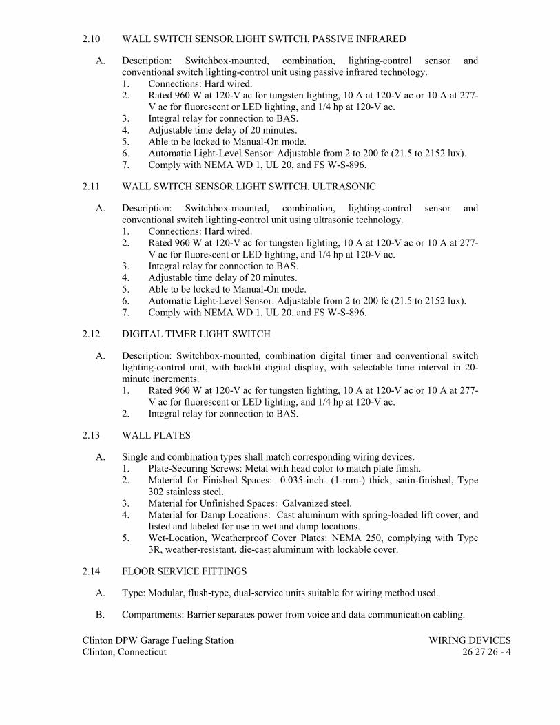
Clinton DPW Garage Fueling Station WIRING DEVICES
Clinton, Connecticut 26 27 26 - 4
2.10 WALL SWITCH SENSOR LIGHT SWITCH, PASSIVE INFRARED
A. Description: Switchbox-mounted, combination, lighting-control sensor and
conventional switch lighting-control unit using passive infrared technology.
1. Connections: Hard wired.
2. Rated 960 W at 120-V ac for tungsten lighting, 10 A at 120-V ac or 10 A at 277-
V ac for fluorescent or LED lighting, and 1/4 hp at 120-V ac.
3. Integral relay for connection to BAS.
4. Adjustable time delay of 20 minutes.
5. Able to be locked to Manual-On mode.
6. Automatic Light-Level Sensor: Adjustable from 2 to 200 fc (21.5 to 2152 lux).
7. Comply with NEMA WD 1, UL 20, and FS W-S-896.
2.11 WALL SWITCH SENSOR LIGHT SWITCH, ULTRASONIC
A. Description: Switchbox-mounted, combination, lighting-control sensor and
conventional switch lighting-control unit using ultrasonic technology.
1. Connections: Hard wired.
2. Rated 960 W at 120-V ac for tungsten lighting, 10 A at 120-V ac or 10 A at 277-
V ac for fluorescent or LED lighting, and 1/4 hp at 120-V ac.
3. Integral relay for connection to BAS.
4. Adjustable time delay of 20 minutes.
5. Able to be locked to Manual-On mode.
6. Automatic Light-Level Sensor: Adjustable from 2 to 200 fc (21.5 to 2152 lux).
7. Comply with NEMA WD 1, UL 20, and FS W-S-896.
2.12 DIGITAL TIMER LIGHT SWITCH
A. Description: Switchbox-mounted, combination digital timer and conventional switch
lighting-control unit, with backlit digital display, with selectable time interval in 20-
minute increments.
1. Rated 960 W at 120-V ac for tungsten lighting, 10 A at 120-V ac or 10 A at 277-
V ac for fluorescent or LED lighting, and 1/4 hp at 120-V ac.
2. Integral relay for connection to BAS.
2.13 WALL PLATES
A. Single and combination types shall match corresponding wiring devices.
1. Plate-Securing Screws: Metal with head color to match plate finish.
2. Material for Finished Spaces: 0.035-inch- (1-mm-) thick, satin-finished, Type
302 stainless steel.
3. Material for Unfinished Spaces: Galvanized steel.
4. Material for Damp Locations: Cast aluminum with spring-loaded lift cover, and
listed and labeled for use in wet and damp locations.
5. Wet-Location, Weatherproof Cover Plates: NEMA 250, complying with Type
3R, weather-resistant, die-cast aluminum with lockable cover.
2.14 FLOOR SERVICE FITTINGS
A. Type: Modular, flush-type, dual-service units suitable for wiring method used.
B. Compartments: Barrier separates power from voice and data communication cabling.

Clinton DPW Garage Fueling Station WIRING DEVICES
Clinton, Connecticut 26 27 26 - 5
C. Service Plate: Rectangular, die-cast aluminum with satin finish.
D. Power Receptacle: NEMA WD 6 Configuration 5-20R, gray finish, unless otherwise
indicated.
2.15 POKE-THROUGH ASSEMBLIES
A. Description:
1. Factory-fabricated and -wired assembly of below-floor junction box with
multichanneled, through-floor raceway/firestop unit and detachable matching
floor service-outlet assembly.
B. Comply with UL 514 scrub water exclusion requirements.
C. Size: Selected to fit nominal 4-inch (100-mm) cored holes in floor and matched to floor
thickness.
D. Fire Rating: Unit is listed and labeled for fire rating of floor-ceiling assembly.
E. Closure Plug: Arranged to close unused 4-inch (100-mm) cored openings and
reestablish fire rating of floor.
2.16 FINISHES
A. Device Color:
1. Wiring Devices Connected to Normal Power System: Ivory unless otherwise
indicated or required by NFPA 70 or device listing.
PART 3 - EXECUTION
3.01 INSTALLATION
A. Comply with NECA 1, including mounting heights listed in that standard, unless
otherwise indicated.
B. Coordination with Other Trades:
1. Protect installed devices and their boxes. Do not place wall finish materials over
device boxes and do not cut holes for boxes with routers that are guided by riding
against outside of boxes.
2. Keep outlet boxes free of plaster, drywall joint compound, mortar, cement,
concrete, dust, paint, and other material that may contaminate the raceway
system, conductors, and cables.
3. Install device boxes in brick or block walls so that the cover plate does not cross
a joint unless the joint is troweled flush with the face of the wall.
4. Install wiring devices after all wall preparation, including painting, is complete.
C. Conductors:
1. Do not strip insulation from conductors until right before they are spliced or
terminated on devices.
2. Strip insulation evenly around the conductor using tools designed for the
purpose. Avoid scoring or nicking of solid wire or cutting strands from stranded
wire.
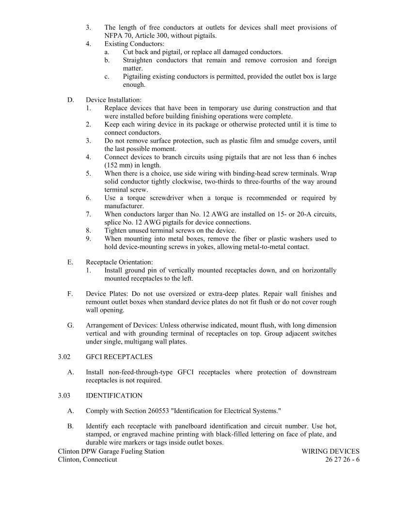
Clinton DPW Garage Fueling Station WIRING DEVICES
Clinton, Connecticut 26 27 26 - 6
3. The length of free conductors at outlets for devices shall meet provisions of
NFPA 70, Article 300, without pigtails.
4. Existing Conductors:
a. Cut back and pigtail, or replace all damaged conductors.
b. Straighten conductors that remain and remove corrosion and foreign
matter.
c. Pigtailing existing conductors is permitted, provided the outlet box is large
enough.
D. Device Installation:
1. Replace devices that have been in temporary use during construction and that
were installed before building finishing operations were complete.
2. Keep each wiring device in its package or otherwise protected until it is time to
connect conductors.
3. Do not remove surface protection, such as plastic film and smudge covers, until
the last possible moment.
4. Connect devices to branch circuits using pigtails that are not less than 6 inches
(152 mm) in length.
5. When there is a choice, use side wiring with binding-head screw terminals. Wrap
solid conductor tightly clockwise, two-thirds to three-fourths of the way around
terminal screw.
6. Use a torque screwdriver when a torque is recommended or required by
manufacturer.
7. When conductors larger than No. 12 AWG are installed on 15- or 20-A circuits,
splice No. 12 AWG pigtails for device connections.
8. Tighten unused terminal screws on the device.
9. When mounting into metal boxes, remove the fiber or plastic washers used to
hold device-mounting screws in yokes, allowing metal-to-metal contact.
E. Receptacle Orientation:
1. Install ground pin of vertically mounted receptacles down, and on horizontally
mounted receptacles to the left.
F. Device Plates: Do not use oversized or extra-deep plates. Repair wall finishes and
remount outlet boxes when standard device plates do not fit flush or do not cover rough
wall opening.
G. Arrangement of Devices: Unless otherwise indicated, mount flush, with long dimension
vertical and with grounding terminal of receptacles on top. Group adjacent switches
under single, multigang wall plates.
3.02 GFCI RECEPTACLES
A. Install non-feed-through-type GFCI receptacles where protection of downstream
receptacles is not required.
3.03 IDENTIFICATION
A. Comply with Section 260553 "Identification for Electrical Systems."
B. Identify each receptacle with panelboard identification and circuit number. Use hot,
stamped, or engraved machine printing with black-filled lettering on face of plate, and
durable wire markers or tags inside outlet boxes.
Clinton DPW Garage Fueling Station WIRING DEVICES
Clinton, Connecticut 26 27 26 - 7
3.04 FIELD QUALITY CONTROL
A. Perform the following tests and inspections:
1. Test Instruments: Use instruments that comply with UL 1436.
2. Test Instrument for Convenience Receptacles: Digital wiring analyzer with
digital readout or illuminated digital-display indicators of measurement.
B. Tests for Convenience Receptacles:
1. Line Voltage: Acceptable range is 105 to 132 V.
2. Percent Voltage Drop under 15-A Load: A value of 6 percent or higher is
unacceptable.
3. Ground Impedance: Values of up to 2 ohms are acceptable.
4. GFCI Trip: Test for tripping values specified in UL 1436 and UL 943.
5. Using the test plug, verify that the device and its outlet box are securely mounted.
6. Tests shall be diagnostic, indicating damaged conductors, high resistance at the
circuit breaker, poor connections, inadequate fault current path, defective
devices, or similar problems. Correct circuit conditions, remove malfunctioning
units and replace with new ones, and retest as specified above.
C. Wiring device will be considered defective if it does not pass tests and inspections.
D. Prepare test and inspection reports.
END OF SECTION 26 27 26

Clinton DPW Garage Fueling Station LED EXTERIOR LIGHTING
Clinton, Connecticut 26 56 19 - 1
SECTION 26 56 19
LED EXTERIOR LIGHTING
PART 1 - GENERAL
1.01 RELATED DOCUMENTS
A. Drawings and general provisions of the Contract, including General and Supplementary
Conditions and Division 01 Specification Sections, apply to this Section.
1.02 SUMMARY
A. Section Includes:
1. Exterior solid-state luminaires that are designed for and exclusively use LED
lamp technology.
2. Luminaire supports.
3. Luminaire-mounted photoelectric relays.
1.03 DEFINITIONS
A. CRI: Color rendering index.
B. Luminaire: Complete lighting unit, including lamp, reflector, and housing.
1.04 ACTION SUBMITTALS
A. Product Data: For each type of luminaire.
1. Arrange in order of luminaire designation.
2. Include data on features, accessories, and finishes.
3. Include physical description and dimensions of luminaire.
4. Lamps, include life, output (lumens, CCT, and CRI), and energy-efficiency data.
5. Photometric data and adjustment factors based on laboratory tests, complying
with IES LM-79 IES LM-80.
a. Manufacturer's Certified Data: Photometric data certified by
manufacturer’s laboratory with a current accreditation under the NVLAP
for Energy Efficient Lighting Products.
b. Testing Agency Certified Data: For indicated luminaires, photometric data
certified by a qualified independent testing agency. Photometric data for
remaining luminaires shall be certified by manufacturer.
6. Wiring diagrams for power, control, and signal wiring.
7. Photoelectric relays.
8. Means of attaching luminaires to supports and indication that the attachment is
suitable for components involved.
B. Shop Drawings: For nonstandard or custom luminaires.
1. Include plans, elevations, sections, and mounting and attachment details.
2. Include details of luminaire assemblies. Indicate dimensions, weights, loads,
required clearances, method of field assembly, components, and location and size
of each field connection.
3. Include diagrams for power, signal, and control wiring.
Clinton DPW Garage Fueling Station LED EXTERIOR LIGHTING
Clinton, Connecticut 26 56 19 - 2
C. Product Schedule: For luminaires and lamps. Use same designations indicated on
Drawings.
1.05 INFORMATIONAL SUBMITTALS
A. Qualification Data: For testing laboratory providing photometric data for luminaires.
B. Seismic Qualification Certificates: For luminaires, accessories, and components, from
manufacturer.
1. Basis for Certification: Indicate whether withstand certification is based on actual
test of assembled components or on calculation.
2. Dimensioned Outline Drawings of Equipment Unit: Identify center of gravity and
locate and describe mounting and anchorage provisions.
3. Detailed description of equipment anchorage devices on which the certification is
based and their installation requirements.
C. Product Certificates: For each type of the following:
1. Luminaire.
D. Product Test Reports: For each luminaire, for tests performed by a qualified testing
agency.
E. Source quality-control reports.
F. Sample warranty.
1.06 CLOSEOUT SUBMITTALS
A. Operation and Maintenance Data: For luminaires to include in operation and
maintenance manuals.
1. Provide a list of all lamp types used on Project. Use ANSI and manufacturers'
codes.
1.07 QUALITY ASSURANCE
A. Luminaire Photometric Data Testing Laboratory Qualifications: Provided by an
independent agency, with the experience and capability to conduct the testing indicated,
that is an NRTL as defined by OSHA in 29 CFR 1910.7, accredited under the NVLAP
for Energy Efficient Lighting Products and complying with applicable IES testing
standards.
B. Provide luminaires from a single manufacturer for each luminaire type.
C. Each luminaire type shall be binned within a three-step MacAdam Ellipse to ensure
color consistency among luminaires.
D. Installer Qualifications: An authorized representative who is trained and approved by
manufacturer.
1. Obtain Architect's approval of luminaires in mockups before starting
installations.
2. Maintain mockups during construction in an undisturbed condition as a standard
for judging the completed work.

Clinton DPW Garage Fueling Station LED EXTERIOR LIGHTING
Clinton, Connecticut 26 56 19 - 3
3. Approval of mockups does not constitute approval of deviations from the
Contract Documents contained in mockups unless Architect specifically approves
such deviations in writing.
4. Subject to compliance with requirements, approved mockups may become part of
the completed Work if undisturbed at time of Substantial Completion.
1.08 DELIVERY, STORAGE, AND HANDLING
A. Protect finishes of exposed surfaces by applying a strippable, temporary protective
covering prior to shipping.
1.09 WARRANTY
A. Warranty: Manufacturer and Installer agree to repair or replace components of
luminaires that fail in materials or workmanship within specified warranty period.
1. Failures include, but are not limited to, the following:
a. Structural failures, including luminaire support components.
b. Faulty operation of luminaires and accessories.
c. Deterioration of metals, metal finishes, and other materials beyond normal
weathering.
2. Warranty Period: 2 years from date of Substantial Completion.
PART 2 - PRODUCTS
2.01 PERFORMANCE REQUIREMENTS
A. Seismic Performance: Luminaires shall withstand the effects of earthquake motions
determined according to ASCE/SEI 7.
B. Seismic Performance: Luminaires and lamps shall be labeled vibration and shock
resistant.
1. The term "withstand" means "the luminaire will remain in place without
separation of any parts when subjected to the seismic forces specified."
2.02 LUMINAIRE REQUIREMENTS
A. Electrical Components, Devices, and Accessories: Listed and labeled as defined in
NFPA 70, by a qualified testing agency, and marked for intended location and
application.
B. UL Compliance: Comply with UL 1598 and listed for wet location.
C. Lamp base complying with ANSI C81.61.
D. Bulb shape complying with ANSI C79.1.
E. CRI of minimum 80. CCT of 2700 K
F. L70 lamp life of 50,000 hours.
G. Lamps dimmable from 100 percent to 0 percent of maximum light output.
H. Internal driver.

Clinton DPW Garage Fueling Station LED EXTERIOR LIGHTING
Clinton, Connecticut 26 56 19 - 4
I. Nominal Operating Voltage: As indicated on plans.
J. In-line Fusing: On the primary for each luminaire.
K. Lamp Rating: Lamp marked for outdoor use.
L. Source Limitations: Obtain luminaires from single source from a single manufacturer.
2.03 LUMINAIRE TYPES
A. As indicated on plans.
2.04 MATERIALS
A. Metal Parts: Free of burrs and sharp corners and edges.
B. Sheet Metal Components: Stainless steel. Form and support to prevent warping and
sagging.
C. Doors, Frames, and Other Internal Access: Smooth operating, free of light leakage
under operating conditions, and designed to permit relamping without use of tools.
Designed to prevent doors, frames, lenses, diffusers, and other components from falling
accidentally during relamping and when secured in operating position. Doors shall be
removable for cleaning or replacing lenses.
2.05 FINISHES
A. Variations in Finishes: Noticeable variations in same piece are unacceptable. Variations
in appearance of adjoining components are acceptable if they are within the range of
approved Samples and are assembled or installed to minimize contrast.
B. Luminaire Finish: Manufacturer's standard paint applied to factory-assembled and -
tested luminaire before shipping. Where indicated, match finish process and color of
pole or support materials.
2.06 LUMINAIRE SUPPORT COMPONENTS
A. Comply with requirements in Section 260529 "Hangers and Supports for Electrical
Systems" for channel and angle iron supports and nonmetallic channel and angle
supports.
PART 3 - EXECUTION
3.01 EXAMINATION
A. Examine substrates, areas, and conditions, with Installer present, for compliance with
requirements for installation tolerances and other conditions affecting performance of
the Work.
B. Examine roughing-in for luminaire electrical conduit to verify actual locations of
conduit connections before luminaire installation.
C. Examine walls, roofs, and canopy ceilings for suitable conditions where luminaires will
be installed.

Clinton DPW Garage Fueling Station LED EXTERIOR LIGHTING
Clinton, Connecticut 26 56 19 - 5
D. Proceed with installation only after unsatisfactory conditions have been corrected.
3.02 GENERAL INSTALLATION REQUIREMENTS
A. Comply with NECA 1.
B. Use fastening methods and materials selected to resist seismic forces defined for the
application and approved by manufacturer.
C. Install lamps in each luminaire.
D. Fasten luminaire to structural support.
E. Supports:
1. Sized and rated for luminaire weight.
2. Able to maintain luminaire position after cleaning and relamping.
3. Support luminaires without causing deflection of finished surface.
4. Luminaire-mounting devices shall be capable of supporting a horizontal force of
100 percent of luminaire weight and a vertical force of 400 percent of luminaire
weight.
5. Attached to structural members in walls Attached to a minimum 1/8 inch (3 mm)
backing plate attached to wall structural members.
F. Wiring Method: Install cables in raceways. Conceal raceways and cables.
G. Install luminaires level, plumb, and square with finished grade unless otherwise
indicated.
H. Coordinate layout and installation of luminaires with other construction.
I. Adjust luminaires that require field adjustment or aiming. Include adjustment of
photoelectric device to prevent false operation of relay by artificial light sources,
favoring a north orientation.
J. Comply with requirements in Section 260519 "Low-Voltage Electrical Power
Conductors and Cables" and 260533 "Raceways and Boxes for Electrical Systems" for
wiring connections and wiring methods.
3.03 CORROSION PREVENTION
A. Aluminum: Do not use in contact with earth or concrete. When in direct contact with a
dissimilar metal, protect aluminum by insulating fittings or treatment.
B. Steel Conduits: Comply with Section 260533 "Raceways and Boxes for Electrical
Systems." In concrete foundations, wrap conduit with 0.010-inch- (0.254-mm-) thick,
pipe-wrapping plastic tape applied with a 50 percent overlap.
3.04 IDENTIFICATION
A. Identify system components, wiring, cabling, and terminals. Comply with requirements
for identification specified in Section 260553 "Identification for Electrical Systems."

Clinton DPW Garage Fueling Station LED EXTERIOR LIGHTING
Clinton, Connecticut 26 56 19 - 6
3.05 FIELD QUALITY CONTROL
A. Inspect each installed luminaire for damage. Replace damaged luminaires and
components.
B. Perform the following tests and inspections:
1. Operational Test: After installing luminaires, switches, and accessories, and after
electrical circuitry has been energized, test units to confirm proper operation.
2. Verify operation of photoelectric controls.
C. Illumination Tests:
1. Measure light intensities at night. Use photometers with calibration referenced to
NIST standards. Comply with the following IES testing guide(s):
a. IES LM-5.
2. Operational Test: After installing luminaires, switches, and accessories, and after
electrical circuitry has been energized, test units to confirm proper operation.
D. Luminaire will be considered defective if it does not pass tests and inspections.
E. Prepare a written report of tests, inspections, observations, and verifications indicating
and interpreting results. If adjustments are made to lighting system, retest to
demonstrate compliance with standards.
3.06 DEMONSTRATION
A. Train owner's maintenance personnel to adjust, operate, and maintain luminaires and
photocell relays.
3.07 ADJUSTING
A. Occupancy Adjustments: When requested within 12 months of date of Substantial
Completion, provide on-site assistance in adjusting the direction of aim of luminaires to
suit occupied conditions. Make up to two visits to Project during other-than-normal
hours for this purpose. Some of this work may be required during hours of darkness.
1. During adjustment visits, inspect all luminaires. Replace lamps or luminaires that
are defective.
2. Parts and supplies shall be manufacturer's authorized replacement parts and
supplies.
3. Adjust the aim of luminares in the presence of the Architect.
END OF SECTION 26 56 19

Clinton DPW Garage Fueling Station
Clinton, Connecticut
EARTH MOVING
31 20 00 - 1
SECTION 31 20 00
EARTH MOVING
PART 1 - GENERAL
1.1 RELATED DOCUMENTS
A. Drawings and general provisions of the Contract, including General and Supplementary
Conditions and Division 01 Specification Sections, apply to this Section.
B. References to the Standard Specifications for this section shall mean the State of
Connecticut Department of Transportation Standard Specifications for Roads, Bridges
and Incidental Construction Form 817 supplemented and amended through the date of
this project bid.
C. 2002 Connecticut Guidelines for Soil Erosion and Sediment Control, DEP Bulletin 34
or as amended through the date of this project bid.
D. 2005 Connecticut State Building Code which includes 2003 International Building
Code, 2009 Connecticut Supplement.
E. 2010 ADA Standards for Accessible Design by the Department of Justice dated
September 15, 2010 or as amended through the date of this project bid.
1.2 SUMMARY
A. Section Includes:
1. Excavating and backfilling for buildings and structures.
2. Subbase course for concrete walks and pavements.
3. Subbase course and base course for asphalt paving.
4. Subsurface drainage backfill for walls and trenches.
5. Excavating and backfilling trenches for utilities and pits for buried utility
structures.
B. Related Requirements:
1.3 DEFINITIONS
A. Backfill: Soil material or controlled low-strength material used to fill an excavation.
1. Initial Backfill: Backfill placed beside and over pipe in a trench, including
haunches to support sides of pipe.
2. Final Backfill: Backfill placed over initial backfill to fill a trench.
B. Base Course: Aggregate layer placed between the subbase course and hot-mix asphalt
paving.

Clinton DPW Garage Fueling Station
Clinton, Connecticut
EARTH MOVING
31 20 00 - 2
C. Bedding Course: Aggregate layer placed over the excavated subgrade in a trench before
laying pipe.
D. Borrow Soil: Satisfactory soil imported from off-site for use as fill or backfill.
E. Drainage Course: Aggregate layer supporting the slab-on-grade that also minimizes
upward capillary flow of pore water.
F. Excavation: Removal of material encountered above subgrade elevations and to lines
and dimensions indicated.
1. Authorized Additional Excavation: Excavation below subgrade elevations or
beyond indicated lines and dimensions as directed by Architect. Authorized
additional excavation and replacement material will be paid for according to
Contract provisions for changes in the Work.
2. Bulk Excavation: Excavation more than 10 feet in width and more than 30 feet
in length.
3. Unauthorized Excavation: Excavation below subgrade elevations or beyond
indicated lines and dimensions without direction by Architect. Unauthorized
excavation, as well as remedial work directed by Architect, shall be without
additional compensation.
G. Fill: Soil materials used to raise existing grades.
H. Rock: Rock material in beds, ledges, unstratified masses, conglomerate deposits, and
boulders of rock material that exceed 1 cu. yd. for bulk excavation or 3/4 cu. yd. for
footing, trench, and pit excavation that cannot be removed by rock-excavating
equipment equivalent to the following in size and performance ratings, without
systematic drilling, ram hammering, ripping, or blasting, when permitted:
1. Equipment for Footing, Trench, and Pit Excavation: Late-model, track-mounted
hydraulic excavator; equipped with a 42-inch- maximum-width, short-tip-radius
rock bucket; rated at not less than 138-hp flywheel power with bucket-curling
force of not less than 28,700 lbf and stick-crowd force of not less than 18,400 lbf
with extra-long reach boom.
2. Equipment for Bulk Excavation: Late-model, track-mounted loader; rated at not
less than 230-hp flywheel power and developing a minimum of 47,992-lbf
breakout force with a general-purpose bare bucket.
I. Structures: Buildings, footings, foundations, retaining walls, slabs, tanks, curbs,
mechanical and electrical appurtenances, or other man-made stationary features
constructed above or below the ground surface.
J. Subbase Course: Aggregate layer placed between the subgrade and base course for hot-
mix asphalt pavement, or aggregate layer placed between the subgrade and a cement
concrete pavement or a cement concrete or hot-mix asphalt walk.
K. Subgrade: Uppermost surface of an excavation or the top surface of a fill or backfill
immediately below subbase, drainage fill, drainage course, or topsoil materials.
L. Utilities: On-site underground pipes, conduits, ducts, and cables as well as underground
services within buildings.

Clinton DPW Garage Fueling Station
Clinton, Connecticut
EARTH MOVING
31 20 00 - 3
1.4 ACTION SUBMITTALS
A. Product Data: For each type of the following manufactured products required:
1. Geotextiles.
2. Controlled low-strength material, including design mixture.
3. Warning tapes.
B. Samples for Verification: For the following products, in sizes indicated below:
1. Geotextile: 12 by 12 inches.
2. Warning Tape: 12 inches long; of each color.
1.5 INFORMATIONAL SUBMITTALS
A. Qualification Data: For qualified testing agency.
B. CONNDOT Certification, classification according to ASTM D 2487, and laboratory
compaction curve according to ASTM D 1557: For each soil material proposed for fill
and backfill as follows:
1. Borrow
2. Processed Aggregate / Processed Coarse Aggregate
3. Subbase
4. Bedding Material / Bedding Course / Select Backfill
5. Controlled / Engineered / Granular fill
6. No. 8 Stone
7. No. 6 Stone Bedding Material
8. No. 67 Stone
9. ASTM C-33 Sand
C. Preexcavation Photographs or Videotape: Show existing conditions of adjoining
construction and site improvements, including finish surfaces that might be
misconstrued as damage caused by earth-moving operations. Submit before earth
moving begins.
D. Test Reports: Submit appropriate reports in accordance with the following criteria
directly from the testing services to the Engineer, with copy to the Contractor:
1. Laboratory collection and analysis of each soil material/source proposed from all
on-site and borrow sources.
2. Verification of suitability of subgrade material, in accordance with specified
requirements.
3. Report of actual unconfined compressive strength and/or results of bearing tests
of each stratum tested.
4. Soil Sampling: Prior to placement of any soil material on site,
representative samples shall be collected and analyzed to verify the fill
material meets the Connecticut Department of Environmental Protection
(CTDEP) and Remediation Standard Regulations (RSRs) requirements.
Samples shall be collected from the source area of the proposed material
prior to excavation and delivery to or movement on the site. Sample

Clinton DPW Garage Fueling Station
Clinton, Connecticut
EARTH MOVING
31 20 00 - 4
analysis frequency will be equal to or greater than 1 sample per 500 cubic
yards of soil.
5. If more than one source of fill will be used, at least one (1) fill sample shall
be collected and laboratory analyzed from each source (even if less than 500
cubic yards of material is obtained from the source).
6. Samples being collected for analysis of Volatile Organic Compounds (VOCs)
will not be composited or mixed.
a. Fill samples will be analyzed by a Connecticut Department of Public
Health certified laboratory for the following constituents:
1) VOCs per EPA Method 8260B;
2) Extractable Total Petroleum Hydrocarbons (ETPH) per CTDEP
approved method;
3) Polynuclear aromatic hydrocarbon (PAHs) compounds per EPA
Method 8270C;
4) Mass and Synthetic Precipitation Leaching Procedure (SPLP) 8
RCRA metals per EPA Methods 6010 and 7471; and
5) Polychlorinated biphenyls (PCBs) per EPA Method 8082.
b. The analyses of the fill samples will be evaluated by the Engineer and the
fill will not be transported to the site or used on site unless the results
demonstrate compliance with the applicable RSR criteria for the site,
which are the Residential Direct Exposure Criteria (DEC) and the GA
Pollutant Mobility Criteria (PMC). The material must be approved by the
Engineer prior to delivery to the site.
7. Testing reports must be submitted within seven calendar days of collection.
E. Construction Staging Plan for Site Grading Activities.
F. Construction schedule for earth moving activities.
G. Material hauling route.
1.6 QUALITY ASSURANCE
A. Blasting: Blasting is NOT permitted.
B. Geotechnical Testing Agency Qualifications: Qualified according to ASTM E 329 and
ASTM D 3740 for testing indicated.
C. Employ and pay for a State Licensed environmental analytical laboratory to collect
samples and perform all testing of the borrow material.
1. Borrow material shall be tested at the rate of once per 500 cubic yards and
representatives samples shall be collected at the source prior to initiation of work.
Samples shall be collected, stored, and transported in accordance with laboratory
recommendations.
1.7 FIELD CONDITIONS
A. Traffic: Minimize interference with adjoining roads, streets, walks, and other adjacent
occupied or used facilities during earth-moving operations.

Clinton DPW Garage Fueling Station
Clinton, Connecticut
EARTH MOVING
31 20 00 - 5
1. Do not close or obstruct streets, walks, or other adjacent occupied or used
facilities without permission from Owner and authorities having jurisdiction.
2. Provide alternate routes around closed or obstructed traffic ways if required by
Owner or authorities having jurisdiction.
B. Utility Locator Service: Notify "Call Before You Dig for area where Project is located
before beginning earth-moving operations.
C. Do not commence earth-moving operations until temporary site fencing and erosion-
and sedimentation-control measures specified in Section 015000 "Temporary Facilities
and Controls" and Section 311000 "Site Clearing" are in place.
D. Do not commence earth-moving operations until plant-protection measures specified in
Section 015639 "Temporary Tree and Plant Protection" are in place.
E. The following practices are prohibited within protection zones:
1. Storage of construction materials, debris, or excavated material.
2. Parking vehicles or equipment.
3. Foot traffic.
4. Erection of sheds or structures.
5. Impoundment of water.
6. Excavation or other digging unless otherwise indicated.
7. Attachment of signs to or wrapping materials around trees or plants unless
otherwise indicated.
F. Do not direct vehicle or equipment exhaust towards protection zones.
G. Prohibit heat sources, flames, ignition sources, and smoking within or near protection
zones.
PART 2 - PRODUCTS
2.1 SOIL MATERIALS
A. General: Provide borrow soil materials when sufficient satisfactory soil materials are
not available from excavations.
B. Satisfactory Soils: Soil Classification Groups GW, GP, GM, SW, SP, and SM
according to ASTM D 2487, or a combination of these groups; free of rock or gravel
larger than 3 inches in any dimension, debris, waste, frozen materials, vegetation, and
other deleterious matter.
C. Unsatisfactory Soils: Soil Classification Groups GC, SC, CL, ML, OL, CH, MH, OH,
and PT according to ASTM D 2487, or a combination of these groups.
1. Unsatisfactory soils also include satisfactory soils not maintained within 2
percent of optimum moisture content at time of compaction.
D. Subbase Material: Imported material shall comply with Article M.02.06 Grading ‘B’ of
the Standard Specifications. Reclaimed aggregate shall satisfy resistance to abrasion
and soundness requirements set forth in Article M.02.06 of the Standard Specification.

Clinton DPW Garage Fueling Station
Clinton, Connecticut
EARTH MOVING
31 20 00 - 6
E. Base Course: Material shall comply with Article M.05.01 Processed Aggregate Base of
the Standard Specifications.
F. Controlled / Engineered / Structural / Granular Fill: Material shall comply with Article
M.02.01 Granular Fill of the Standard Specifications.
Material shall consist of sandy gravel, gravelly sand, free of organic matter, snow, ice
or other unsuitable materials. Reclaimed aggregate shall satisfy resistance to abrasion
and soundness requirements set forth in Article M.02.06 of the Standard Specification.
Reclaimed aggregate shall not be used under building footprints.
G. Bedding Course and Select Backfill: Materials shall comply with Section M.08.01-21
of the Standard Specifications for bedding material.
H. No. 4, No. 6 No. 67 and No. 8 Stone: Materials shall comply with Section M.01.01 of
the Standard Specifications respectively.
I. Sand: ASTM C 33/C 33M; fine aggregate.
J. Impervious Fill: Clayey gravel and sand mixture capable of compacting to a dense state.
2.2 GEOTEXTILES
A. All products must be listed on CONNDOT Qualified product list with can be obtained
at http://www.ct.gov/dot/LIB/dot/documents/dresearch/conndot_qpl.pdf.
B. Subsurface Drainage Geotextile: Nonwoven needle-punched geotextile, manufactured
for subsurface drainage applications, made from polyolefins or polyesters; with
elongation greater than 50 percent; complying with AASHTO M 288 and the following,
measured per test methods referenced:
1. Survivability: Class 2; AASHTO M 288.
2. Survivability: As follows:
a. Grab Tensile Strength: 157 lbf; ASTM D 4632.
b. Sewn Seam Strength: 142 lbf; ASTM D 4632.
c. Tear Strength: 56 lbf; ASTM D 4533.
d. Puncture Strength: 56 lbf; ASTM D 4833.
3. Apparent Opening Size: No. 60 sieve, maximum; ASTM D 4751.
4. Permittivity: 0.2 per second, minimum; ASTM D 4491.
5. UV Stability: 50 percent after 500 hours' exposure; ASTM D 4355.
C. Separation Geotextile: Woven geotextile fabric, manufactured for separation
applications, made from polyolefins or polyesters; with elongation less than 50 percent;
complying with AASHTO M 288 and the following, measured per test methods
referenced:
1. Survivability: Class 2; AASHTO M 288.
2. Survivability: As follows:
a. Grab Tensile Strength: 247 lbf; ASTM D 4632.
b. Sewn Seam Strength: 222 lbf; ASTM D 4632.

Clinton DPW Garage Fueling Station
Clinton, Connecticut
EARTH MOVING
31 20 00 - 7
c. Tear Strength: 90 lbf; ASTM D 4533.
d. Puncture Strength: 90 lbf; ASTM D 4833.
3. Apparent Opening Size: No. 60 sieve, maximum; ASTM D 4751.
4. Permittivity: 0.02 per second, minimum; ASTM D 4491.
5. UV Stability: 50 percent after 500 hours' exposure; ASTM D 4355.
D. Geotextile for use in Trench: Sections for “Sanitary Sewer Main” and “Sanitary Sewer
Lateral” shall be Mirafi 140N or Supac 5NP Filter Fabric or approved equal.
2.3 ACCESSORIES
A. Detectable Warning Tape: Acid- and alkali-resistant, polyethylene film warning tape
manufactured for marking and identifying underground utilities, a minimum of 6 inches
wide and 4 mils thick, continuously inscribed with a description of the utility, with
metallic core encased in a protective jacket for corrosion protection, detectable by metal
detector when tape is buried up to 30 inches deep; colored as follows:
1. Red: Electric.
2. Yellow: Gas, oil, steam, and dangerous materials.
3. Orange: Telephone and other communications.
4. Blue: Water systems.
5. Green: Sewer systems.
PART 3 - EXECUTION
3.1 PREPARATION
A. Protect structures, utilities, sidewalks, pavements, and other facilities from damage
caused by settlement, lateral movement, undermining, washout, and other hazards
created by earth-moving operations.
B. Protect and maintain erosion and sedimentation controls during earth-moving
operations.
C. Protect subgrades and foundation soils from freezing temperatures and frost. Remove
temporary protection before placing subsequent materials.
3.2 DEWATERING
A. Prevent surface water and ground water from entering excavations, from ponding on
prepared subgrades, and from flooding Project site and surrounding area.
B. Protect subgrades from softening, undermining, washout, and damage by rain or water
accumulation.
1. Reroute surface water runoff away from excavated areas. Do not allow water to
accumulate in excavations. Do not use excavated trenches as temporary drainage
ditches.
Clinton DPW Garage Fueling Station
Clinton, Connecticut
EARTH MOVING
31 20 00 - 8
3.3 EXPLOSIVES
A. Explosives: Do not use explosives.
3.4 EXCAVATION, GENERAL
A. Unclassified Excavation: Excavate to subgrade elevations regardless of the
character of surface and subsurface conditions encountered. Unclassified
excavated materials may include rock, soil materials, and obstructions. No changes
in the Contract Sum or the Contract Time will be authorized for rock excavation
or removal of obstructions.
1. If excavated materials intended for fill and backfill include unsatisfactory soil
materials and rock, replace with satisfactory soil materials.
B. Rock Excavation:
1. Remove rock to lines and grades indicated to permit installation of permanent
construction without exceeding the following dimensions:
a. 24 inches outside of concrete forms other than at footings.
b. 12 inches outside of concrete forms at footings.
c. 6 inches outside of minimum required dimensions of concrete cast against
grade.
d. Outside dimensions of concrete walls indicated to be cast against rock
without forms or exterior waterproofing treatments.
e. 6 inches beneath bottom of concrete slabs-on-grade.
f. 6 inches beneath pipe in trenches, and the greater of 24 inches wider than
pipe or 42 inches wide with vertical walls.
2. Wherever rock to be excavated is encountered, the Contractor shall strip or
expose the rock to such an extent that in the Owner’s opinion the necessary
measurements can be taken. The Contractor shall provide the Owner with a
survey by a licensed land surveyor indicating top of rock elevations at points of
intersection on a rectilinear grid with lines spaced sufficiently close to show
accurately the rock surface contours. At the Owner’s option, an additional
survey may be furnished by the Owner from a licensed surveyor. The volume of
material conforming to the above limits derived from this survey data will be the
basis of payment of this item. Quantity shall be calculated by the contractor and
provided to the engineer for review and verification
3. Rock excavation is to be paid at the unit prices established below (Basis For
Payment): Prices include backfill with on-site excavated material if it is suitable.
Prices also include all excavation and disposal of all surplus or unsuitable
material. Prices include costs of shoring, de-watering, and sloping for sides of
excavation as necessary. Payment and credit amounts shall be determined based
on the limits identified above. The total quantity of earth or rock excavation
encountered in each depth payment category shall be paid for at its respective
unit price as shown below. For example, in a 15’ trench the first 6’ will be paid
for at the 0’ - 6’ price; the next 4’ will be paid for at the over 6’ - 10’ price and
the next 5’ will be paid for at the over 10’ - 15’ price. Thus three different price
brackets will prevail.
4. If the conditions of the excavation work indicated are clearly of a special nature
as identified by the Contractor and confirmed by the Engineer, the Contractor
may ask the Owner for reconsideration of the established unit prices and if

Clinton DPW Garage Fueling Station
Clinton, Connecticut
EARTH MOVING
31 20 00 - 9
granted, the unit prices will not apply, and prices will be negotiated in
accordance with Article 13 “Compensations for Changes in the Work” of the
General Conditions.
3.5 EXCAVATION FOR STRUCTURES
A. Excavate to indicated elevations and dimensions within a tolerance of plus or minus 1
inch. If applicable, extend excavations a sufficient distance from structures for placing
and removing concrete formwork, for installing services and other construction, and for
inspections.
1. Excavations for Footings and Foundations: Do not disturb bottom of excavation.
Excavate by hand to final grade just before placing concrete reinforcement. Trim
bottoms to required lines and grades to leave solid base to receive other work.
2. Pile Foundations: Stop excavations 6 to 12 inches above bottom of pile cap
before piles are placed. After piles have been driven, remove loose and displaced
material. Excavate to final grade, leaving solid base to receive concrete pile caps.
3. Excavation for Underground Tanks, Basins, and Mechanical or Electrical Utility
Structures: Excavate to elevations and dimensions indicated within a tolerance of
plus or minus 1 inch. Do not disturb bottom of excavations intended as bearing
surfaces.
B. Excavations at Edges of Tree- and Plant-Protection Zones:
1. Excavate by hand or with an air spade to indicated lines, cross sections,
elevations, and subgrades. If excavating by hand, use narrow-tine spading forks
to comb soil and expose roots. Do not break, tear, or chop exposed roots. Do not
use mechanical equipment that rips, tears, or pulls roots.
2. Cut and protect roots according to requirements in Section 015639 "Temporary
Tree and Plant Protection."
3.6 EXCAVATION FOR WALKS AND PAVEMENTS
A. Excavate surfaces under walks and pavements to indicated lines, cross sections,
elevations, and subgrades.
3.7 EXCAVATION FOR UTILITY TRENCHES
A. Excavate trenches to indicated gradients, lines, depths, and elevations.
1. Beyond building perimeter, excavate trenches to allow installation of top of pipe
below frost line.
B. Excavate trenches to uniform widths to provide the following clearance on each side of
pipe or conduit. Excavate trench walls vertically from trench bottom to 12 inches higher
than top of pipe or conduit unless otherwise indicated.
1. Clearance: 12 inches each side of pipe or conduit.
C. Trench Bottoms: Excavate and shape trench bottoms to provide uniform bearing and
support of pipes and conduit. Shape subgrade to provide continuous support for bells,

Clinton DPW Garage Fueling Station
Clinton, Connecticut
EARTH MOVING
31 20 00 - 10
joints, and barrels of pipes and for joints, fittings, and bodies of conduits. Remove
projecting stones and sharp objects along trench subgrade.
1. For pipes and conduit less than 6 inches in nominal diameter, hand-excavate
trench bottoms and support pipe and conduit on an undisturbed subgrade.
2. For pipes and conduit 6 inches or larger in nominal diameter, shape bottom of
trench to support bottom 90 degrees of pipe or conduit circumference. Fill
depressions with tamped sand backfill.
3. For flat-bottomed, multiple-duct conduit units, hand-excavate trench bottoms and
support conduit on an undisturbed subgrade.
4. Excavate trenches 6 inches deeper than elevation required in rock or other
unyielding bearing material to allow for bedding course.
D. Trenches in Tree- and Plant-Protection Zones:
1. Hand-excavate to indicated lines, cross sections, elevations, and subgrades. Use
narrow-tine spading forks to comb soil and expose roots. Do not break, tear, or
chop exposed roots. Do not use mechanical equipment that rips, tears, or pulls
roots.
2. Do not cut main lateral roots or taproots; cut only smaller roots that interfere with
installation of utilities.
3. Cut and protect roots according to requirements in Section 015639 "Temporary
Tree and Plant Protection."
3.8 SUBGRADE INSPECTION
A. Notify Architect when excavations have reached required subgrade.
B. If Architect determines that unsatisfactory soil is present, continue excavation and
replace with compacted backfill or fill material as directed.
C. Proof-roll subgrade below the building slabs and pavements with a pneumatic-tired and
loaded 10-wheel, tandem-axle dump truck weighing not less than 15 tons to identify
soft pockets and areas of excess yielding. Do not proof-roll wet or saturated subgrades.
1. Completely proof-roll subgrade in one direction, repeating proof-rolling in
direction perpendicular to first direction. Limit vehicle speed to 3 mph.
2. Excavate soft spots, unsatisfactory soils, and areas of excessive pumping or
rutting, as determined by Architect, and replace with compacted backfill or fill as
directed.
D. Authorized additional excavation and replacement material will be paid for according to
Contract provisions for changes in the Work.
E. Reconstruct subgrades damaged by freezing temperatures, frost, rain, accumulated
water, or construction activities, as directed by Architect, without additional
compensation.

Clinton DPW Garage Fueling Station
Clinton, Connecticut
EARTH MOVING
31 20 00 - 11
3.9 UNAUTHORIZED EXCAVATION
A. Fill unauthorized excavation under foundations or wall footings by extending bottom
elevation of concrete foundation or footing to excavation bottom, without altering top
elevation. Lean concrete fill, with 28-day compressive strength of 2500 psi, may be
used when approved by Architect.
1. Fill unauthorized excavations under other construction, pipe, or conduit as
directed by Architect.
3.10 STORAGE OF SOIL MATERIALS
A. Stockpile borrow soil materials and excavated satisfactory soil materials without
intermixing. Place, grade, and shape stockpiles to drain surface water. Cover to prevent
windblown dust.
1. Stockpile soil materials away from edge of excavations. Do not store within drip
line of remaining trees.
3.11 GENERAL BACKFILL
A. Place and compact backfill in excavations promptly, but not before completing the
following:
1. Construction below finish grade including, where applicable, subdrainage,
dampproofing, waterproofing, and perimeter insulation.
2. Surveying locations of underground utilities for Record Documents.
3. Testing and inspecting underground utilities.
4. Removing concrete formwork.
5. Removing trash and debris.
6. Removing temporary shoring, bracing, and sheeting.
7. Installing permanent or temporary horizontal bracing on horizontally supported
walls.
B. Place backfill on subgrades free of mud, frost, snow, or ice.
3.12 UTILITY TRENCH BACKFILL
A. Place backfill on subgrades free of mud, frost, snow, or ice.
B. Place and compact bedding course on trench bottoms and where indicated. Shape
bedding course to provide continuous support for bells, joints, and barrels of pipes and
for joints, fittings, and bodies of conduits.
C. Trenches under Footings: Backfill trenches excavated under footings and within 18
inches of bottom of footings with controlled fill; fill with concrete to elevation of
bottom of footings. Concrete is specified in Section 033000 "Cast-in-Place Concrete."
D. Trenches under Roadways: Provide 4-inch thick, concrete-base slab support for piping
or conduit less than 30 inches below surface of roadways. After installing and testing,
completely encase piping or conduit in a minimum of 4 inches of concrete before

Clinton DPW Garage Fueling Station
Clinton, Connecticut
EARTH MOVING
31 20 00 - 12
backfilling or placing roadway subbase course. Concrete is specified in Section 033000
"Cast-in-Place Concrete."
E. Backfill voids with satisfactory soil while removing shoring and bracing.
F. Initial Backfill:
1. Soil Backfill: Place and compact initial backfill of granular fill, free of particles
larger than 1 inch in any dimension, to a height of 12 inches over the pipe or
conduit.
a. Carefully compact initial backfill under pipe haunches and compact evenly
up on both sides and along the full length of piping or conduit to avoid
damage or displacement of piping or conduit. Coordinate backfilling with
utilities testing.
G. Final Backfill:
1. Soil Backfill: Place and compact final backfill of satisfactory soil to final
subgrade elevation.
2. Controlled Low-Strength Material: Place final backfill of controlled low-strength
material to final subgrade elevation.
H. Warning Tape: Install warning tape directly above utilities, 12 inches below finished
grade, except 6 inches below subgrade under pavements and slabs.
3.13 SOIL FILL
A. Plow, scarify, bench, or break up sloped surfaces steeper than 1 vertical to 4 horizontal
so fill material will bond with existing material.
B. Place and compact fill material in layers to required elevations as follows:
1. Under grass and planted areas, use satisfactory soil material.
2. Under walks and pavements, use granular fill.
3. Under steps and ramps, use granular fill.
4. Under building slabs, use granular fill.
5. Under footings and foundations, use granular fill.
C. Place soil fill on subgrades free of mud, frost, snow, or ice.
3.14 SOIL MOISTURE CONTROL
A. Uniformly moisten or aerate subgrade and each subsequent fill or backfill soil layer
before compaction to within 2 percent of optimum moisture content.
1. Do not place backfill or fill soil material on surfaces that are muddy, frozen, or
contain frost or ice.
2. Remove and replace, or scarify and air dry, otherwise satisfactory soil material
that exceeds optimum moisture content by 2 percent and is too wet to compact to
specified dry unit weight.

Clinton DPW Garage Fueling Station
Clinton, Connecticut
EARTH MOVING
31 20 00 - 13
3.15 COMPACTION OF SOIL BACKFILLS AND FILLS
A. Place backfill, granular fill, and fill soil materials in layers not more than 12 inches in
loose depth for material compacted by heavy compaction equipment and not more than
6 inches in loose depth for material located in confined areas or compacted by hand-
operated tampers.
B. Place backfill and fill soil materials evenly on all sides of structures to required
elevations and uniformly along the full length of each structure.
C. Compact soil materials to not less than the following percentages of maximum dry unit
weight according to ASTM D 1557:
1. Under structures, building slabs, steps, and pavements, scarify and recompact top
12 inches of existing subgrade and each layer of backfill or fill soil material at 95
percent.
2. Under walkways, scarify and recompact top 6 inches below subgrade and
compact each layer of backfill or fill soil material at 92 percent.
3. Under turf or unpaved areas, scarify and recompact top 6 inches below subgrade
and compact each layer of backfill or fill soil material at 92 percent.
4. For utility trenches, compact each layer of initial and final backfill soil material
at 92 percent.
3.16 GRADING
A. General: Uniformly grade areas to a smooth surface, free of irregular surface changes.
Comply with compaction requirements and grade to cross sections, lines, and elevations
indicated.
1. Provide a smooth transition between adjacent existing grades and new grades.
2. Cut out soft spots, fill low spots, and trim high spots to comply with required
surface tolerances.
B. Site Rough Grading: Slope grades to direct water away from buildings and to prevent
ponding. Finish subgrades to elevations required to achieve indicated finish elevations,
within the following subgrade tolerances:
1. Turf or Unpaved Areas: Plus or minus 1 inch.
2. Walks: Plus or minus 1 inch.
3. Pavements: Plus or minus 1/2 inch.
C. Grading inside Building Lines: Finish subgrade to a tolerance of 1/2 inch when tested
with a 10-foot straightedge.
3.17 SUBSURFACE DRAINAGE
A. Field under drain, see C-813 for detail.
1. Compact each filter material layer to 85 percent of maximum dry unit weight
according to ASTM D 698.
B. Rain garden under drain, see C-810 for detail.

Clinton DPW Garage Fueling Station
Clinton, Connecticut
EARTH MOVING
31 20 00 - 14
1. Compact each filter material layer to 85 percent of maximum dry unit weight
according to ASTM D 698.
3.18 SUBBASE AND BASE COURSES UNDER PAVEMENTS AND WALKS
A. Place subbase course and base course on subgrades free of mud, frost, snow, or ice.
B. On prepared subgrade, place subbase course and base course under pavements and
walks as follows:
1. Place base course material over subbase course under hot-mix asphalt pavement.
2. Shape subbase course and base course to required crown elevations and cross-
slope grades.
3. Place subbase course and base course 6 inches or less in compacted thickness in a
single layer.
4. Place subbase course and base course that exceeds 6 inches in compacted
thickness in layers of equal thickness, with no compacted layer more than 6
inches thick or less than 3 inches thick.
5. Compact subbase course and base course at optimum moisture content to
required grades, lines, cross sections, and thickness to not less than 95 percent of
maximum dry unit weight according to ASTM D 1557.
C. Pavement Shoulders: Place shoulders along edges of subbase course and base course to
prevent lateral movement. Construct shoulders, at least 12 inches wide, of satisfactory
soil materials and compact simultaneously with each subbase and base layer to not less
than 95 percent of maximum dry unit weight according to ASTM D 1557.
3.19 DRAINAGE COURSE UNDER CONCRETE SLABS-ON-GRADE
A. Place drainage course on subgrades free of mud, frost, snow, or ice.
B. On prepared subgrade, place and compact drainage course under cast-in-place concrete
slabs-on-grade as follows:
1. Install subdrainage geotextile on prepared subgrade according to manufacturer's
written instructions, overlapping sides and ends.
2. Place drainage course 6 inches or less in compacted thickness in a single layer.
3. Place drainage course that exceeds 6 inches in compacted thickness in layers of
equal thickness, with no compacted layer more than 6 inches thick or less than 3
inches thick.
4. Compact each layer of drainage course to required cross sections and thicknesses
to not less than 95 percent of maximum dry unit weight according to
ASTM D 698.
3.20 FIELD QUALITY CONTROL
A. Special Inspections: Owner will engage a qualified special inspector to perform the
following special inspections:
1. Determine prior to placement of fill that site has been prepared in compliance
with requirements.

Clinton DPW Garage Fueling Station
Clinton, Connecticut
EARTH MOVING
31 20 00 - 15
2. Determine that fill material classification and maximum lift thickness comply
with requirements.
3. Determine, during placement and compaction that in-place density of compacted
fill complies with requirements.
B. Testing Agency: Owner will engage a qualified geotechnical engineering testing agency
to perform tests and inspections.
C. Allow testing agency to inspect and test subgrades and each fill or backfill layer.
Proceed with subsequent earth moving only after test results for previously completed
work comply with requirements.
D. Footing Subgrade: At footing subgrades, at least one test of each soil stratum will be
performed to verify design bearing capacities. Subsequent verification and approval of
other footing subgrades may be based on a visual comparison of subgrade with tested
subgrade when approved by Architect.
E. Testing agency will test compaction of soils in place according to ASTM D 1556,
ASTM D 2167, ASTM D 2937, and ASTM D 6938, as applicable. Tests will be
performed at the following locations and frequencies:
1. Paved and Building Slab Areas: At subgrade and at each compacted fill and
backfill layer, at least one test for every 2000 sq. ft. or less of paved area or
building slab but in no case fewer than three tests.
2. Foundation Wall Backfill: At each compacted backfill layer, at least one test for
every 100 feet or less of wall length but no fewer than two tests.
3. Trench Backfill: At each compacted initial and final backfill layer, at least one
test for every 150 feet or less of trench length but no fewer than two tests.
F. When testing agency reports that subgrades, fills, or backfills have not achieved degree
of compaction specified, scarify and moisten or aerate, or remove and replace soil
materials to depth required; recompact and retest until specified compaction is obtained.
3.21 PROTECTION
A. Protecting Graded Areas: Protect newly graded areas from traffic, freezing, and erosion.
Keep free of trash and debris.
B. Repair and reestablish grades to specified tolerances where completed or partially
completed surfaces become eroded, rutted, settled, or where they lose compaction due
to subsequent construction operations or weather conditions.
1. Scarify or remove and replace soil material to depth as directed by Architect;
reshape and recompact.
C. Where settling occurs before Project correction period elapses, remove finished
surfacing, backfill with additional soil material, compact, and reconstruct surfacing.
1. Restore appearance, quality, and condition of finished surfacing to match
adjacent work, and eliminate evidence of restoration to greatest extent possible.

Clinton DPW Garage Fueling Station
Clinton, Connecticut
EARTH MOVING
31 20 00 - 16
3.22 DISPOSAL OF SURPLUS AND WASTE MATERIALS
A. Remove surplus satisfactory soil and waste materials, including unsatisfactory soil,
trash, and debris, and legally dispose of them off Owner's property.
END OF SECTION 31 20 00

SECTION 31 21 00
DISPOSAL OF CONTROLLED MATERIALS
Clinton DPW Garage Fueling Station DISPOSAL OF CONTROLLED MATERIALS
Clinton, Connecticut 31 21 00 - 1
PART 1 - GENERAL
1.1 SECTION INCLUDES
A. The work included under this item consists of the Contractor's requirements for the loading,
transportation and final off-site disposal of all Controlled Materials within the contract limits as
specified in Section 017620-Excavation and Handling of Controlled Materials.
B. This item shall apply to Controlled Materials generated by the Contractor and all
subcontractors.
C. The Contractor must use an approved, permitted treatment/disposal facility for State-regulated
solid waste disposal. Identification of the proposed disposal facility must be included with the
Contactor’s bid as required in the bid documents.
1.2 RELATED SECTIONS
A. Section 011110 – Environmental Health and Safety
B. Section 017620 - Excavation and Handling of Controlled Materials
C. Section 026500 – Underground Storage Tank Cleaning and Removal
1.3 SUBMITTALS
A. Bidders shall submit with their bid documents the name, address, telephone number and fax
number of the proposed treatment/disposal facility, which shall include the name and phone
number of an authorized representative of the facility. This letter shall also include a copy of
the facility acceptance criteria and a copy of the facility’s operational permit.
Failure to comply with the above requirements may result in rejection of the bid.
B. No facility may be substituted for the one designated in the Contractor's submittals unless
approved by the Owner in writing.
C. The contractor shall submit copies of transportation and disposal documentation, including bills
of lading and weight tickets/receipts for disposal of Controlled Materials. The Contractor shall
prepare and submit copies of all manifests for disposal of Controlled Materials.
1.4 REGULATORY REQUIRMENTS
A. Conform to all applicable Federal, State and local regulations, including local permits, if
applicable.

Clinton DPW Garage Fueling Station DISPOSAL OF CONTROLLED MATERIALS
Clinton, Connecticut 31 21 00 - 2
B. Conform to 29 CFR Section 1926, “Safety and Health Regulations for Construction”, as
required.
PART 2 - PRODUCTS
2.1 TRANSPORTATION
A. Vehicles used to transport Controlled Materials must be free from leaks, equipped with load
tarpaulins, and any discharge openings must be securely closed during transportation.
PART 3 - EXECUTION
3.1 CONSTRUCTION METHODS
A. All Controlled Materials handled and transported for disposal will require Special Handling
according to the requirements of these specifications and any applicable federal, state or local
regulations
B. Contractors that work with, or have the potential to be exposed to, Controlled Materials in the
course of UST closure activities shall meet OSHA requirements for health and safety provisions
which may include the use of chemical protective clothing, personal protective equipment,
implementation of engineering controls, air and personnel monitoring, and decontamination
procedures.
C. The Contractor shall minimize the spread of Controlled Materials during handling and
transportation for disposal. Transport vehicles used to move Controlled Materials at the project
site shall be free from leaks. Discharge openings must be securely closed during transportation.
D. The Contractor shall keep paved areas including, but not limited to, areas adjacent to
excavations, roadways leading to and from the project site, parking areas, and public roadways
free from dirt, dust, Controlled Materials, or other materials. If such materials are deposited,
spilled, or spread, such material shall be removed promptly, and properly disposed of to the
satisfaction of the Engineer no later than the end of each working day or as directed by the
Engineer.
3.2 DISPOSAL
A. The Contractor shall be responsible for coordinating treatment/disposal facility approval,
loading, transportation, and ultimate disposal of the material at the facility. No claim for delay
will be considered based upon the facility failing to meet the Contractor's production
schedule or based upon the Contractor's failure to accommodate the disposal/treatment
facility requirements as identified above.
B. It shall be the Contractor's responsibility to comply with applicable over-the-road Federal, State,
or local weight limits and all rules and regulations applicable to the transportation of Controlled
Materials.

Clinton DPW Garage Fueling Station DISPOSAL OF CONTROLLED MATERIALS
Clinton, Connecticut 31 21 00 - 3
C. Manifests or bills of lading, whichever is required, shall be prepared by the Contractor and
signed by an authorized representative of the Owner as "Generator" for each load of Controlled
Materials (truck) that leaves the site. The Contractor shall forward the appropriate original
copies of manifests or bills of lading to the Engineer and/or Owner’s representative the same
day the materials leave the project site.
D. Discharge openings on trucks used for the transportation of soils must be securely closed during
transportation, and load tarpaulins must be deployed. Trucks deemed unacceptable for use by
the Engineer shall not be used for the transportation of Controlled Materials.
E. Following load-out each day, residual Controlled Materials resulting from spillage shall be
removed from the loading area and returned to appropriate stockpiles.
PART 4 – MEASUREMENT AND PAYMENTFollowing
4.1 MEASUREMENT
Disposal of Controlled Materials Soil will be measured as the actual net weight in tons of
“Controlled Material” delivered to the treatment/disposal facility. Such determinations shall be
made by measuring each hauling vehicle on the permanent scales at the treatment/recycling
facility. Total weight shall be the summation of weigh bills issued by the facility. Contractor
shall submit his proposed Unit Price along with his bid and shall include a detailed breakdown
of costs to justify the proposed Unit Price. Final Unit Price shall be subject to negotiation prior
to contract award. Contractors Unit Price shall include the cost for removal of the material from
the temporary stockpile, material handling, transportation and disposal at a treatment/recycling
center. This item shall also include furnishing, placing, and compacting any required granular
fill needed to replace soils disposed of as Controlled Material Soil, preparation of manifests or
bills of lading, all fees paid, and all equipment, materials, tools, and labor incidental to loading,
transporting, treating/recycling and disposal of Controlled Materials. This item pays for the
Contractors incremental costs associated with the disposal of Controlled Materials above and
beyond costs for handling and disposal of non-Controlled Materials already included in the
contract. No additonal measurement or payment shall be made for establishment of the
Temporary Waste Stockpile Area, Dust Control, Soil Characterization, or Equipment
decontamination, which shall be part of the Contractors lump sum bid.
4.2 PAYMENT
A. Payment under this item shall be at the Contract Unit Price per ton of material for "Disposal of
Controlled Material Soils”.
Item No. PAY ITEMS PAY UNITS
312100-A Disposal of Controlled Material Soil Ton
END OF SECTION 0312100

Clinton DPW Garage Fueling Station ASPHALT PAVING
Clinton, Connecticut 32 12 16 - 1
SECTION 32 12 16
ASPHALT PAVING
PART 1 - GENERAL
1.1 RELATED DOCUMENTS
A. Drawings and general provisions of the Contract, including General and Supplementary
Conditions and Division 01 Specification Sections, apply to this Section.
B. References to the Standard Specifications for this section shall mean the State of
Connecticut Department of Transportation Standard Specifications for Roads, Bridges
and Incidental Construction Form 817 supplemented and amended through the date of
this project bid.
C. 2002 Connecticut Guidelines for Soil Erosion and Sediment Control, DEP Bulletin 34
or as amended through the date of this project bid.
D. 2005 Connecticut State Building Code which includes 2003 International Building
Code, 2009 Connecticut Supplement.
E. 2010 ADA Standards for Accessible Design by the Department of Justice dated
September 15, 2010 or as amended through the date of this project bid.
1.2 SUMMARY
A. Section Includes:
1. Hot-mix asphalt patching.
2. Hot-mix asphalt paving.
B. Related Requirements:
1. Section 312000 "Earth Moving" for subgrade preparation, fill material, unbound-
aggregate subbase and base courses, and aggregate pavement shoulders.
1.3 PREINSTALLATION MEETINGS
A. Preinstallation Conference: Conduct conference at Project site.
1. Review methods and procedures related to hot-mix asphalt paving including, but
not limited to, the following:
a. Review proposed sources of paving materials, including capabilities and
location of plant that will manufacture hot-mix asphalt.
b. Review requirements for protecting paving work, including restriction of
traffic during installation period and for remainder of construction period.

Clinton DPW Garage Fueling Station ASPHALT PAVING
Clinton, Connecticut 32 12 16 - 2
1.4 ACTION SUBMITTALS
A. Product Data: For each type of product.
1. Job-Mix Designs: Certification, by the Connecticut Department of
Transportation, of approval of each job mix proposed for the Work. Certification
shall include name of project covered under these specifications.
1.5 INFORMATIONAL SUBMITTALS
A. Qualification Data: For manufacturer and testing agency.
B. Material Certificates: For each paving material. Include statement that mixes containing
recycled materials will perform equal to mixes produced from all new materials.
C. Material Test Reports: For each paving material, by a qualified testing agency.
D. Field quality-control reports.
1.6 QUALITY ASSURANCE
A. Manufacturer Qualifications: A paving-mix manufacturer registered with and approved
by the Connecticut Department of Transportation.
B. Testing Agency Qualifications: Qualified according to ASTM D 3666 for testing
indicated.
C. Regulatory Requirements: Comply with materials, workmanship, and other applicable
requirements of the Connecticut Department of Transportation for asphalt paving work.
1. Measurement and payment provisions and safety program submittals included in
standard specifications do not apply to this Section.
1.7 FIELD CONDITIONS
A. Environmental Limitations: Do not apply asphalt materials if subgrade is wet or
excessively damp, if rain is imminent or expected before time required for adequate
cure, or if the following conditions are not met:
1. Tack Coat: Minimum surface temperature of 60 deg F.
2. Asphalt Base Course: Minimum surface temperature of 40 deg F and rising at
time of placement.
3. Asphalt Surface Course: Minimum surface temperature of 60 deg F at time of
placement.

Clinton DPW Garage Fueling Station ASPHALT PAVING
Clinton, Connecticut 32 12 16 - 3
PART 2 - PRODUCTS
2.1 MIXES
A. Hot-Mix Asphalt: Dense, hot-laid, hot-mix asphalt plant mixes approved by the
Connecticut Department of Transportation and complying with the following
requirements:
1. Comply with Form 817 Section M.04 – Bituminous Concrete Materials.
PART 3 - EXECUTION
3.1 EXAMINATION
A. Verify that subgrade is dry and in suitable condition to begin paving.
B. Proof-roll subgrade below pavements with heavy pneumatic-tired equipment to identify
soft pockets and areas of excess yielding. Do not proof-roll wet or saturated subgrades.
1. Completely proof-roll subgrade in one direction. Limit vehicle speed to 3 mph.
2. Proof roll with a loaded 10-wheel, tandem-axle dump truck weighing not less
than 15 tons.
3. Excavate soft spots, unsatisfactory soils, and areas of excessive pumping or
rutting, as determined by Architect, and replace with compacted backfill or fill as
directed.
C. Proceed with paving only after unsatisfactory conditions have been corrected.
3.2 PATCHING
A. Asphalt Pavement: Saw cut perimeter of patch and excavate existing pavement section
to sound base. Excavate rectangular or trapezoidal patches, extending 12 inches into
perimeter of adjacent sound pavement, unless otherwise indicated. Cut excavation faces
vertically. Remove excavated material. Recompact existing unbound-aggregate base
course to form new subgrade.
B. Portland Cement Concrete Pavement: Break cracked slabs and roll as required to reseat
concrete pieces firmly.
1. Pump hot undersealing asphalt under rocking slab until slab is stabilized or, if
necessary, crack slab into pieces and roll to reseat pieces firmly.
2. Remove disintegrated or badly cracked pavement. Excavate rectangular or
trapezoidal patches, extending into perimeter of adjacent sound pavement, unless
otherwise indicated. Cut excavation faces vertically. Recompact existing
unbound-aggregate base course to form new subgrade.
C. Tack Coat: Before placing patch material, apply tack coat uniformly to vertical asphalt
surfaces abutting the patch. Apply at a rate of 0.05 to 0.15 gal./sq. yd..

Clinton DPW Garage Fueling Station ASPHALT PAVING
Clinton, Connecticut 32 12 16 - 4
1. Allow tack coat to cure undisturbed before applying hot-mix asphalt paving.
2. Avoid smearing or staining adjoining surfaces, appurtenances, and surroundings.
Remove spillages and clean affected surfaces.
D. Placing Patch Material: Fill excavated pavement areas with hot-mix asphalt base mix
for full thickness of patch and, while still hot, compact flush with adjacent surface.
E. Placing Patch Material: Partially fill excavated pavements with hot-mix asphalt base
mix and, while still hot, compact. Cover asphalt base course with compacted, hot-mix
surface layer finished flush with adjacent surfaces.
3.3 REPAIRS
A. Leveling Course: Install and compact leveling course consisting of hot-mix asphalt
surface course to level sags and fill depressions deeper than 1 inch in existing
pavements.
1. Install leveling wedges in compacted lifts not exceeding 3 inches thick.
B. Crack and Joint Filling: Remove existing joint filler material from cracks or joints to a
depth of 1/4 inch.
1. Clean cracks and joints in existing hot-mix asphalt pavement.
2. Use emulsified-asphalt slurry to seal cracks and joints less than 1/4 inch wide.
Fill flush with surface of existing pavement and remove excess.
3. Use hot-applied joint sealant to seal cracks and joints more than 1/4 inch wide.
Fill flush with surface of existing pavement and remove excess.
3.4 SURFACE PREPARATION
A. General: Immediately before placing asphalt materials, remove loose and deleterious
material from substrate surfaces. Ensure that prepared subgrade is ready to receive
paving.
B. Tack Coat: Apply uniformly to surfaces of existing pavement at a rate of 0.05 to 0.15
gal./sq. yd..
1. Allow tack coat to cure undisturbed before applying hot-mix asphalt paving.
2. Avoid smearing or staining adjoining surfaces, appurtenances, and surroundings.
Remove spillages and clean affected surfaces.
3.5 PLACING HOT-MIX ASPHALT
A. Machine place hot-mix asphalt on prepared surface, spread uniformly, and strike off.
Place asphalt mix by hand in areas inaccessible to equipment in a manner that prevents
segregation of mix. Place each course to required grade, cross section, and thickness
when compacted.
1. Place hot-mix asphalt base course in number of lifts and thicknesses indicated.
2. Place hot-mix asphalt surface course in single lift.
Clinton DPW Garage Fueling Station ASPHALT PAVING
Clinton, Connecticut 32 12 16 - 5
3. Spread mix at a minimum temperature of 265 deg F.
4. Begin applying mix along centerline of crown for crowned sections and on high
side of one-way slopes unless otherwise indicated.
5. Regulate paver machine speed to obtain smooth, continuous surface free of pulls
and tears in asphalt-paving mat.
B. Place paving in consecutive strips not less than 10 feet wide unless infill edge strips of a
lesser width are required.
1. After first strip has been placed and rolled, place succeeding strips and extend
rolling to overlap previous strips. Overlap mix placement about 1 to 1-1/2 inches
from strip to strip to ensure proper compaction of mix along longitudinal joints.
2. Complete a section of asphalt base course before placing asphalt surface course.
C. Promptly correct surface irregularities in paving course behind paver. Use suitable hand
tools to remove excess material forming high spots. Fill depressions with hot-mix
asphalt to prevent segregation of mix; use suitable hand tools to smooth surface.
3.6 JOINTS
A. Construct joints to ensure a continuous bond between adjoining paving sections.
Construct joints free of depressions, with same texture and smoothness as other sections
of hot-mix asphalt course.
1. Clean contact surfaces and apply tack coat to joints.
2. Offset longitudinal joints, in successive courses, a minimum of 6 inches.
3. Offset transverse joints, in successive courses, a minimum of 24 inches.
4. Construct transverse joints at each point where paver ends a day's work and
resumes work at a subsequent time. Construct these joints using either
"bulkhead" or "papered" method according to AI MS-22, for both "Ending a
Lane" and "Resumption of Paving Operations."
5. Compact joints as soon as hot-mix asphalt will bear roller weight without
excessive displacement.
6. Compact asphalt at joints to a density within 2 percent of specified course
density.
3.7 COMPACTION
A. General: Begin compaction as soon as placed hot-mix paving will bear roller weight
without excessive displacement. Compact hot-mix paving with hot, hand tampers or
with vibratory-plate compactors in areas inaccessible to rollers.
1. Complete compaction before mix temperature cools to 185 deg F.
B. Breakdown Rolling: Complete breakdown or initial rolling immediately after rolling
joints and outside edge. Examine surface immediately after breakdown rolling for
indicated crown, grade, and smoothness. Correct laydown and rolling operations to
comply with requirements.

Clinton DPW Garage Fueling Station ASPHALT PAVING
Clinton, Connecticut 32 12 16 - 6
C. Intermediate Rolling: Begin intermediate rolling immediately after breakdown rolling
while hot-mix asphalt is still hot enough to achieve specified density. Continue rolling
until hot-mix asphalt course has been uniformly compacted to the following density:
1. Density: Not less than 92 percent of reference maximum theoretical density
according to AASHTO T209, or greater than 97 percent.
D. Finish Rolling: Finish roll paved surfaces to remove roller marks while hot-mix asphalt
is still warm.
E. Edge Shaping: While surface is being compacted and finished, trim edges of pavement
to proper alignment. Bevel edges while asphalt is still hot; compact thoroughly.
F. Repairs: Remove paved areas that are defective or contaminated with foreign materials
and replace with fresh, hot-mix asphalt. Compact by rolling to specified density and
surface smoothness.
G. Protection: After final rolling, do not permit vehicular traffic on pavement until it has
cooled and hardened.
H. Erect barricades to protect paving from traffic until mixture has cooled enough not to
become marked.
3.8 INSTALLATION TOLERANCES
A. Pavement Thickness: Compact each course to produce the thickness indicated within
the following tolerances:
1. Base Course: Plus or minus 1/2 inch.
2. Surface Course: Plus 1/4 inch, no minus.
B. Pavement Surface Smoothness: Compact each course to produce a surface smoothness
within the following tolerances as determined by using a 10-foot straightedge applied
transversely or longitudinally to paved areas:
1. Base Course: 1/4 inch.
2. Surface Course: 1/8 inch.
3. Crowned Surfaces: Test with crowned template centered and at right angle to
crown. Maximum allowable variance from template is 1/4 inch.
3.9 FIELD QUALITY CONTROL
A. Testing Agency: Engage a qualified testing agency to perform tests and inspections.
B. Thickness: In-place compacted thickness of hot-mix asphalt courses will be determined
according to ASTM D 3549.

Clinton DPW Garage Fueling Station ASPHALT PAVING
Clinton, Connecticut 32 12 16 - 7
C. Surface Smoothness: Finished surface of each hot-mix asphalt course will be tested for
compliance with smoothness tolerances.
D. In-Place Density: Testing agency will take samples of uncompacted paving mixtures
and compacted pavement according to AASHTO T 168.
1. Reference maximum theoretical density will be determined by averaging results
from four samples of hot-mix asphalt-paving mixture delivered daily to site,
prepared according to AASHTO T209, and compacted according to job-mix
specifications.
2. In-place density of compacted pavement will be determined by testing core
samples according to ASTM D 1188 or ASTM D 2726.
a. One core sample will be taken for every 1000 sq. yd. or less of installed
pavement, with no fewer than three cores taken.
b. Field density of in-place compacted pavement may also be determined by
nuclear method according to ASTM D 2950 and correlated with
ASTM D 1188 or ASTM D 2726.
E. Replace and compact hot-mix asphalt where core tests were taken.
F. Remove and replace or install additional hot-mix asphalt where test results or
measurements indicate that it does not comply with specified requirements.
END OF SECTION 32 12 16

Clinton DPW Garage Fueling Station CONCRETE PAVING
Clinton, Connecticut 32 13 13 - 1
SECTION 32 13 13
CONCRETE PAVING
PART 1 - GENERAL
1.1 RELATED DOCUMENTS
A. Drawings and general provisions of the Contract, including General and Supplementary
Conditions and Division 01 Specification Sections, apply to this Section.
B. References to the Standard Specifications for this section shall mean the State of
Connecticut Department of Transportation Standard Specifications for Roads, Bridges
and Incidental Construction Form 817 supplemented and amended through the date of
this project bid.
C. 2002 Connecticut Guidelines for Soil Erosion and Sediment Control, DEP Bulletin 34
or as amended through the date of this project bid.
D. 2005 Connecticut State Building Code which includes 2003 International Building
Code, 2009 Connecticut Supplement.
E. 2010 ADA Standards for Accessible Design by the Department of Justice dated
September 15, 2010 or as amended through the date of this project bid.
1.2 SUMMARY
A. Section Includes Concrete Paving Including the Following:
1. Driveways.
2. Pads.
3. Curbs.
4. Walks.
1.3 DEFINITIONS
A. Cementitious Materials: Portland cement alone or in combination with one or more of
blended hydraulic cement, fly ash, slag cement, and other pozzolans.
B. W/C Ratio: The ratio by weight of water to cementitious materials.
1.4 PREINSTALLATION MEETINGS
A. Preinstallation Conference: Conduct conference at Project site.
1. Review methods and procedures related to concrete paving, including but not
limited to, the following:

Clinton DPW Garage Fueling Station CONCRETE PAVING
Clinton, Connecticut 32 13 13 - 2
a. Concrete mixture design.
b. Quality control of concrete materials and concrete paving construction
practices.
2. Require representatives of each entity directly concerned with concrete paving to
attend, including the following:
a. Contractor's superintendent.
b. Independent testing agency responsible for concrete design mixtures.
c. Ready-mix concrete manufacturer.
d. Concrete paving Subcontractor.
e. Manufacturer's representative of stamped concrete paving system used for
stamped detectable warnings.
1.5 ACTION SUBMITTALS
A. Product Data: For each type of product.
B. Samples for Initial Selection: For each type of product, ingredient, or admixture
requiring color selection.
C. Samples for Verification: For each type of product or exposed finish, prepared as
Samples of size indicated below:
1. Exposed Aggregate: 10-lb Sample of each mix.
D. Design Mixtures: For each concrete paving mixture. Include alternate design mixtures
when characteristics of materials, Project conditions, weather, test results, or other
circumstances warrant adjustments.
1.6 INFORMATIONAL SUBMITTALS
A. Qualification Data: For qualified Installer of stamped detectable warnings, ready-mix
concrete manufacturer and testing agency.
B. Material Certificates: For the following, from manufacturer:
1. Cementitious materials.
2. Steel reinforcement and reinforcement accessories.
3. Admixtures.
4. Curing compounds.
5. Applied finish materials.
6. Bonding agent or epoxy adhesive.
7. Joint fillers.
C. Field quality-control reports.
1.7 QUALITY ASSURANCE
A. Stamped Detectable Warning Installer Qualifications: An employer of workers trained
and approved by manufacturer of stamped concrete paving systems.

Clinton DPW Garage Fueling Station CONCRETE PAVING
Clinton, Connecticut 32 13 13 - 3
B. Ready-Mix-Concrete Manufacturer Qualifications: A firm experienced in
manufacturing ready-mixed concrete products and that complies with
ASTM C 94/C 94M requirements for production facilities and equipment.
1. Manufacturer certified according to NRMCA's "Certification of Ready Mixed
Concrete Production Facilities" (Quality Control Manual - Section 3, "Plant
Certification Checklist").
C. Testing Agency Qualifications: Qualified according to ASTM C 1077 and ASTM E 329
for testing indicated.
1. Personnel conducting field tests shall be qualified as ACI Concrete Field Testing
Technician, Grade 1, according to ACI CP-1 or an equivalent certification
program.
1.8 PRECONSTRUCTION TESTING
A. Preconstruction Testing Service: Engage a qualified independent testing agency to
perform preconstruction testing on concrete paving mixtures.
1.9 FIELD CONDITIONS
A. Traffic Control: Maintain access for vehicular and pedestrian traffic as required for
other construction activities.
B. Cold-Weather Concrete Placement: Protect concrete work from physical damage or
reduced strength that could be caused by frost, freezing, or low temperatures. Comply
with ACI 306.1 and the following:
1. When air temperature has fallen to or is expected to fall below 40 deg F,
uniformly heat water and aggregates before mixing to obtain a concrete mixture
temperature of not less than 50 deg F and not more than 80 deg F at point of
placement.
2. Do not use frozen materials or materials containing ice or snow.
3. Do not use calcium chloride, salt, or other materials containing antifreeze agents
or chemical accelerators unless otherwise specified and approved in design
mixtures.
C. Hot-Weather Concrete Placement: Comply with ACI 301 and as follows when hot-
weather conditions exist:
1. Cool ingredients before mixing to maintain concrete temperature below 90 deg F
at time of placement. Chilled mixing water or chopped ice may be used to control
temperature, provided water equivalent of ice is calculated in total amount of
mixing water. Using liquid nitrogen to cool concrete is Contractor's option.
2. Cover steel reinforcement with water-soaked burlap, so steel temperature will not
exceed ambient air temperature immediately before embedding in concrete.
3. Fog-spray forms, steel reinforcement, and subgrade just before placing concrete.
Keep subgrade moisture uniform without standing water, soft spots, or dry areas.

Clinton DPW Garage Fueling Station CONCRETE PAVING
Clinton, Connecticut 32 13 13 - 4
PART 2 - PRODUCTS
2.1 CONCRETE, GENERAL
A. ACI Publications: Comply with ACI 301 unless otherwise indicated.
2.2 FORMS
A. Form Materials: Plywood, metal, metal-framed plywood, or other approved panel-type
materials to provide full-depth, continuous, straight, and smooth exposed surfaces.
1. Use flexible or uniformly curved forms for curves with a radius of 100 feet or
less. Do not use notched and bent forms.
B. Form-Release Agent: Commercially formulated form-release agent that will not bond
with, stain, or adversely affect concrete surfaces and that will not impair subsequent
treatments of concrete surfaces.
2.3 STEEL REINFORCEMENT
A. Plain-Steel Welded-Wire Reinforcement: ASTM A 1064/A 1064M, fabricated from
steel wire into flat sheets.
B. Deformed-Steel Welded-Wire Reinforcement: ASTM A 1064/A 1064M, flat sheet.
C. Reinforcing Bars: ASTM A 615/A 615M, Grade 60; deformed.
D. Steel Bar Mats: ASTM A 184/A 184M; with ASTM A 615/A 615M, Grade 60
deformed bars; assembled with clips.
E. Plain-Steel Wire: ASTM A 1064/A 1064M.
F. Deformed-Steel Wire: ASTM A 1064/A 1064M.
G. Joint Dowel Bars: ASTM A 615/A 615M, Grade 60 plain-steel bars. Cut bars true to
length with ends square and free of burrs.
H. Tie Bars: ASTM A 615/A 615M, Grade 60; deformed.
I. Hook Bolts: ASTM A 307, Grade A, internally and externally threaded. Design hook-
bolt joint assembly to hold coupling against paving form and in position during
concreting operations, and to permit removal without damage to concrete or hook bolt.
J. Bar Supports: Bolsters, chairs, spacers, and other devices for spacing, supporting, and
fastening reinforcing bars, welded-wire reinforcement, and dowels in place.
Manufacture bar supports according to CRSI's "Manual of Standard Practice" from steel
wire, plastic, or precast concrete of greater compressive strength than concrete
specified, and as follows:
1. Equip wire bar supports with sand plates or horizontal runners where base
material will not support chair legs.

Clinton DPW Garage Fueling Station CONCRETE PAVING
Clinton, Connecticut 32 13 13 - 5
2.4 CONCRETE MATERIALS
A. Comply with Section M.03 of the Standard Specifications. Mix composition shall
comply with Class “F”.
B. Water: Potable and complying with ASTM C 94/C 94M.
2.5 CURING MATERIALS
A. Absorptive Cover: AASHTO M 182, Class 3, burlap cloth made from jute or kenaf,
weighing approximately 9 oz./sq. yd. dry.
B. Moisture-Retaining Cover: ASTM C 171, polyethylene film or white burlap-
polyethylene sheet.
C. Water: Potable.
D. Evaporation Retarder: Waterborne, monomolecular, film forming, manufactured for
application to fresh concrete.
E. Clear, Waterborne, Membrane-Forming Curing Compound: ASTM C 309, Type 1,
Class B, dissipating.
2.6 RELATED MATERIALS
A. Joint Fillers: ASTM D 1751, asphalt-saturated cellulosic fiber in preformed strips.
B. Epoxy-Bonding Adhesive: ASTM C 881/C 881M, two-component epoxy resin capable
of humid curing and bonding to damp surfaces; of class suitable for application
temperature, of grade complying with requirements, and of the following types:
1. Types I and II, nonload bearing, Types IV and V, load bearing, for bonding
hardened or freshly mixed concrete to hardened concrete.
C. Chemical Surface Retarder: Water-soluble, liquid, set retarder with color dye, for
horizontal concrete surface application, capable of temporarily delaying final hardening
of concrete to a depth of 1/8 to 1/4 inch.
2.7 CONCRETE MIXTURES
A. Prepare design mixtures, proportioned according to ACI 301, for each type and strength
of normal-weight concrete, and as determined by either laboratory trial mixtures or field
experience.
1. Use a qualified independent testing agency for preparing and reporting proposed
concrete design mixtures for the trial batch method.
2. When automatic machine placement is used, determine design mixtures and
obtain laboratory test results that comply with or exceed requirements.
B. Proportion mixtures to provide normal-weight concrete with the following properties:
1. Compressive Strength (28 Days): Class “F” per the Standard Specifications.
2. Maximum Water-Cementitious Materials Ratio at Point of Placement: 0.53

Clinton DPW Garage Fueling Station CONCRETE PAVING
Clinton, Connecticut 32 13 13 - 6
3. Slump Limit: 4 inches, plus or minus 1 inch.
C. Add air-entraining admixture at manufacturer's prescribed rate to result in normal-
weight concrete at point of placement having an air content as follows:
1. Air Content: 5-7 percent.
D. Limit water-soluble, chloride-ion content in hardened concrete to 0.15 percent by
weight of cement.
E. Chemical Admixtures: Use admixtures according to manufacturer's written instructions.
1. Use water-reducing and retarding admixture when required by high temperatures,
low humidity, or other adverse placement conditions.
2.8 CONCRETE MIXING
A. Ready-Mixed Concrete: Measure, batch, and mix concrete materials and concrete
according to ASTM C 94/C 94M. Furnish batch certificates for each batch discharged
and used in the Work.
1. When air temperature is between 85 and 90 deg F, reduce mixing and delivery
time from 1-1/2 hours to 75 minutes; when air temperature is above 90 deg F,
reduce mixing and delivery time to 60 minutes.
2.9 STAINLESS STEEL ISLAND FORM
A. 12 gauge stainless steel provided by formex permanent steel forms, river side steel or
approved equal.
PART 3 - EXECUTION
3.1 EXAMINATION
A. Examine exposed subgrades and subbase surfaces for compliance with requirements for
dimensional, grading, and elevation tolerances.
B. Proof-roll prepared subbase surface below concrete paving to identify soft pockets and
areas of excess yielding.
1. Completely proof-roll subbase in one direction. Limit vehicle speed to 3 mph.
2. Proof-roll with a pneumatic-tired and loaded, 10-wheel, tandem-axle dump truck
weighing not less than 15 tons.
3. Correct subbase with soft spots and areas of pumping or rutting exceeding depth
of 1/2 inch according to requirements in Section 312000 "Earth Moving."
C. Proceed with installation only after unsatisfactory conditions have been corrected.
Clinton DPW Garage Fueling Station CONCRETE PAVING
Clinton, Connecticut 32 13 13 - 7
3.2 PREPARATION
A. Remove loose material from compacted subbase surface immediately before placing
concrete.
3.3 EDGE FORMS AND SCREED CONSTRUCTION
A. Set, brace, and secure edge forms, bulkheads, and intermediate screed guides to
required lines, grades, and elevations. Install forms to allow continuous progress of
work and so forms can remain in place at least 24 hours after concrete placement.
B. Clean forms after each use and coat with form-release agent to ensure separation from
concrete without damage.
3.4 STEEL REINFORCEMENT INSTALLATION
A. General: Comply with CRSI's "Manual of Standard Practice" for fabricating, placing,
and supporting reinforcement.
B. Clean reinforcement of loose rust and mill scale, earth, ice, or other bond-reducing
materials.
C. Arrange, space, and securely tie bars and bar supports to hold reinforcement in position
during concrete placement. Maintain minimum cover to reinforcement.
D. Install welded-wire reinforcement in lengths as long as practicable. Lap adjoining
pieces at least one full mesh, and lace splices with wire. Offset laps of adjoining widths
to prevent continuous laps in either direction.
E. Install fabricated bar mats in lengths as long as practicable. Handle units to keep them
flat and free of distortions. Straighten bends, kinks, and other irregularities, or replace
units as required before placement. Set mats for a minimum 2-inch overlap of adjacent
mats.
3.5 JOINTS
A. General: Form construction, isolation, and contraction joints and tool edges true to line,
with faces perpendicular to surface plane of concrete. Construct transverse joints at
right angles to centerline unless otherwise indicated.
1. When joining existing paving, place transverse joints to align with previously
placed joints unless otherwise indicated.
B. Construction Joints: Set construction joints at side and end terminations of paving and
at locations where paving operations are stopped for more than one-half hour unless
paving terminates at isolation joints.
1. Continue steel reinforcement across construction joints unless otherwise
indicated. Do not continue reinforcement through sides of paving strips unless
otherwise indicated.
2. Provide tie bars at sides of paving strips where indicated.
Clinton DPW Garage Fueling Station CONCRETE PAVING
Clinton, Connecticut 32 13 13 - 8
3. Butt Joints: Use bonding agent at joint locations where fresh concrete is placed
against hardened or partially hardened concrete surfaces.
4. Keyed Joints: Provide preformed keyway-section forms or bulkhead forms with
keys unless otherwise indicated. Embed keys at least 1-1/2 inches into concrete.
5. Doweled Joints: Install dowel bars and support assemblies at joints where
indicated. Lubricate or coat with asphalt one-half of dowel length to prevent
concrete bonding to one side of joint.
C. Isolation Joints: Form isolation joints of preformed joint-filler strips abutting concrete
curbs, catch basins, manholes, inlets, structures, other fixed objects, and where
indicated.
1. Locate expansion joints at intervals of 15 feet unless otherwise indicated.
2. Extend joint fillers full width and depth of joint.
3. Terminate joint filler not less than 1/2 inch or more than 1 inch below finished
surface if joint sealant is indicated.
4. Place top of joint filler flush with finished concrete surface if joint sealant is not
indicated.
5. Furnish joint fillers in one-piece lengths. Where more than one length is required,
lace or clip joint-filler sections together.
6. During concrete placement, protect top edge of joint filler with metal, plastic, or
other temporary preformed cap. Remove protective cap after concrete has been
placed on both sides of joint.
D. Contraction Joints: Form weakened-plane contraction joints, sectioning concrete into
areas as indicated. Construct contraction joints for a depth equal to at least one-fourth of
the concrete thickness, as follows, to match jointing of existing adjacent concrete
paving:
1. Grooved Joints: Form contraction joints after initial floating by grooving and
finishing each edge of joint with grooving tool to a 1/4-inch radius. Repeat
grooving of contraction joints after applying surface finishes
a. Tolerance: Ensure that grooved joints are within 3 inches either way from
centers of dowels.
2. Sawed Joints: Form contraction joints with power saws equipped with
shatterproof abrasive or diamond-rimmed blades. Cut 1/8-inch- wide joints into
concrete when cutting action will not tear, abrade, or otherwise damage surface
and before developing random contraction cracks.
a. Tolerance: Ensure that sawed joints are within 3 inches either way from
centers of dowels.
3. Doweled Contraction Joints: Install dowel bars and support assemblies at joints
where indicated. Lubricate or coat with asphalt one-half of dowel length to
prevent concrete bonding to one side of joint.
E. Edging: After initial floating, tool edges of paving, gutters, curbs, and joints in concrete
with an edging tool to a 1/4-inch radius. Repeat tooling of edges after applying surface
finishes.

Clinton DPW Garage Fueling Station CONCRETE PAVING
Clinton, Connecticut 32 13 13 - 9
3.6 CONCRETE PLACEMENT
A. Before placing concrete, inspect and complete formwork installation, steel
reinforcement, and items to be embedded or cast-in.
B. Remove snow, ice, or frost from subbase surface and steel reinforcement before placing
concrete. Do not place concrete on frozen surfaces.
C. Moisten subbase to provide a uniform dampened condition at time concrete is placed.
Do not place concrete around manholes or other structures until they are at required
finish elevation and alignment.
D. Comply with ACI 301 requirements for measuring, mixing, transporting, and placing
concrete.
E. Do not add water to concrete during delivery or at Project site. Do not add water to
fresh concrete after testing.
F. Deposit and spread concrete in a continuous operation between transverse joints. Do not
push or drag concrete into place or use vibrators to move concrete into place.
G. Consolidate concrete according to ACI 301 by mechanical vibrating equipment
supplemented by hand spading, rodding, or tamping.
1. Consolidate concrete along face of forms and adjacent to transverse joints with
an internal vibrator. Keep vibrator away from joint assemblies, reinforcement, or
side forms. Use only square-faced shovels for hand spreading and consolidation.
Consolidate with care to prevent dislocating reinforcement dowels and joint
devices.
H. Screed paving surface with a straightedge and strike off.
I. Commence initial floating using bull floats or darbies to impart an open-textured and
uniform surface plane before excess moisture or bleedwater appears on the surface. Do
not further disturb concrete surfaces before beginning finishing operations or spreading
surface treatments.
J. Curbs and Gutters: Use design mixture for automatic machine placement. Produce
curbs and gutters to required cross section, lines, grades, finish, and jointing.
3.7 FLOAT FINISHING
A. General: Do not add water to concrete surfaces during finishing operations.
B. Float Finish: Begin the second floating operation when bleedwater sheen has
disappeared and concrete surface has stiffened sufficiently to permit operations. Float
surface with power-driven floats or by hand floating if area is small or inaccessible to
power units. Finish surfaces to true planes. Cut down high spots and fill low spots.
Refloat surface immediately to uniform granular texture.
1. Medium-to-Fine-Textured Broom Finish: Draw a soft-bristle broom across float-
finished concrete surface, perpendicular to line of traffic, to provide a uniform,
fine-line texture.

Clinton DPW Garage Fueling Station CONCRETE PAVING
Clinton, Connecticut 32 13 13 - 10
3.8 CONCRETE PROTECTION AND CURING
A. General: Protect freshly placed concrete from premature drying and excessive cold or
hot temperatures.
B. Comply with ACI 306.1 for cold-weather protection.
C. Evaporation Retarder: Apply evaporation retarder to concrete surfaces if hot, dry, or
windy conditions cause moisture loss approaching 0.2 lb/sq. ft. x h before and during
finishing operations. Apply according to manufacturer's written instructions after
placing, screeding, and bull floating or darbying concrete but before float finishing.
D. Begin curing after finishing concrete but not before free water has disappeared from
concrete surface.
E. Curing Methods: Cure concrete by moisture curing, moisture-retaining-cover curing,
curing compound or a combination of these as follows:
1. Moisture Curing: Keep surfaces continuously moist for not less than seven days
with the following materials:
a. Water.
b. Continuous water-fog spray.
c. Absorptive cover, water saturated and kept continuously wet. Cover
concrete surfaces and edges with 12-inch lap over adjacent absorptive
covers.
2. Moisture-Retaining-Cover Curing: Cover concrete surfaces with moisture-
retaining cover, placed in widest practicable width, with sides and ends lapped at
least 12 inches, and sealed by waterproof tape or adhesive. Immediately repair
any holes or tears occurring during installation or curing period, using cover
material and waterproof tape.
3. Curing Compound: Apply uniformly in continuous operation by power spray or
roller according to manufacturer's written instructions. Recoat areas subjected to
heavy rainfall within three hours after initial application. Maintain continuity of
coating, and repair damage during curing period.
3.9 PAVING TOLERANCES
A. Comply with tolerances in ACI 117 and as follows:
1. Elevation: 3/4 inch.
2. Thickness: Plus 3/8 inch, minus 1/4 inch.
3. Surface: Gap below 10-feet- long; unleveled straightedge not to exceed 1/2 inch.
4. Alignment of Tie-Bar End Relative to Line Perpendicular to Paving Edge: 1/2
inch per 12 inches of tie bar.
5. Lateral Alignment and Spacing of Dowels: 1 inch.
6. Vertical Alignment of Dowels: 1/4 inch.
7. Alignment of Dowel-Bar End Relative to Line Perpendicular to Paving Edge: 1/4
inch per 12 inches of dowel.
8. Joint Spacing: 3 inches.
9. Contraction Joint Depth: Plus 1/4 inch, no minus.
10. Joint Width: Plus 1/8 inch, no minus.

Clinton DPW Garage Fueling Station CONCRETE PAVING
Clinton, Connecticut 32 13 13 - 11
3.10 FIELD QUALITY CONTROL
A. Testing Agency: Engage a qualified testing agency to perform tests and inspections.
B. Testing Services: Testing and inspecting of composite samples of fresh concrete
obtained according to ASTM C 172/C 172M shall be performed according to the
following requirements:
1. Testing Frequency: Obtain at least one composite sample for each 100 cu. yd. or
fraction thereof of each concrete mixture placed each day.
a. When frequency of testing will provide fewer than five compressive-
strength tests for each concrete mixture, testing shall be conducted from at
least five randomly selected batches or from each batch if fewer than five
are used.
2. Slump: ASTM C 143/C 143M; one test at point of placement for each composite
sample, but not less than one test for each day's pour of each concrete mixture.
Perform additional tests when concrete consistency appears to change.
3. Air Content: ASTM C 231/C 231M, pressure method; one test for each
composite sample, but not less than one test for each day's pour of each concrete
mixture.
4. Concrete Temperature: ASTM C 1064/C 1064M; one test hourly when air
temperature is 40 deg F and below and when it is 80 deg F and above, and one
test for each composite sample.
5. Compression Test Specimens: ASTM C 31/C 31M; cast and laboratory cure one
set of three standard cylinder specimens for each composite sample.
6. Compressive-Strength Tests: ASTM C 39/C 39M; test one specimen at seven
days and two specimens at 28 days.
a. A compressive-strength test shall be the average compressive strength
from two specimens obtained from same composite sample and tested at
28 days.
C. Strength of each concrete mixture will be satisfactory if average of any three
consecutive compressive-strength tests equals or exceeds specified compressive
strength and no compressive-strength test value falls below specified compressive
strength by more than 500 psi.
D. Test results shall be reported in writing to Architect, concrete manufacturer, and
Contractor within 48 hours of testing. Reports of compressive-strength tests shall
contain Project identification name and number, date of concrete placement, name of
concrete testing and inspecting agency, location of concrete batch in Work, design
compressive strength at 28 days, concrete mixture proportions and materials,
compressive breaking strength, and type of break for both 7- and 28-day tests.
E. Nondestructive Testing: Impact hammer, sonoscope, or other nondestructive device
may be permitted by Architect but will not be used as sole basis for approval or
rejection of concrete.
F. Additional Tests: Testing and inspecting agency shall make additional tests of concrete
when test results indicate that slump, air entrainment, compressive strengths, or other
requirements have not been met, as directed by Architect.
Clinton DPW Garage Fueling Station CONCRETE PAVING
Clinton, Connecticut 32 13 13 - 12
G. Concrete paving will be considered defective if it does not pass tests and inspections.
H. Additional testing and inspecting, at Contractor's expense, will be performed to
determine compliance of replaced or additional work with specified requirements.
I. Prepare test and inspection reports.
3.11 REPAIR AND PROTECTION
A. Remove and replace concrete paving that is broken, damaged, or defective or that does
not comply with requirements in this Section. Remove work in complete sections from
joint to joint unless otherwise approved by Architect.
B. Drill test cores, where directed by Architect, when necessary to determine magnitude of
cracks or defective areas. Fill drilled core holes in satisfactory paving areas with
portland cement concrete bonded to paving with epoxy adhesive.
C. Protect concrete paving from damage. Exclude traffic from paving for at least 14 days
after placement. When construction traffic is permitted, maintain paving as clean as
possible by removing surface stains and spillage of materials as they occur.
D. Maintain concrete paving free of stains, discoloration, dirt, and other foreign material.
Sweep paving not more than two days before date scheduled for Substantial Completion
inspections.
END OF SECTION 32 13 13
SECTION 33 41 00
STORM DRAINAGE
Clinton DPW Garage Fueling Station
Clinton, Connecticut
STORM DRAINAGE
33 41 00 - 1
PART 1 - GENERAL
1.1 RELATED DOCUMENTS
A. Drawings and general provisions of the Contract, including General and Supplementary
Conditions and Division 1 Specification Sections, apply to this Section.
B. References to the Standard Specifications for this section shall mean the State of Connecticut
Department of Transportation Standard Specifications for Roads, Bridges and Incidental
Construction Form 816 supplemented and amended through the date of this project bid.
C. 2002 Connecticut Guidelines for Soil Erosion and Sediment Control, DEP Bulletin 34 as
amended through the date of this project bid.
1.2 SUMMARY
A. Section Includes:
1. Pipe and fittings.
2. Nonpressure transition couplings.
3. Cleanouts.
4. Drains.
5. Encasement for piping.
6. Manholes.
7. Catch basins.
8. Stormwater inlets.
9. Stormwater detention structures.
10. Pipe outlets.
1.3 SUBMITTALS
A. Product Data: For each type of product indicated.
B. Shop Drawings:
1. Manholes: Include plans, elevations, sections, details, frames, and covers.
2. Catch basins. Include plans, elevations, sections, details, frames, covers, and grates.
3. Storm drainage pipe.
4. Yard Drain. Include plans, elevations, sections, details, frames, covers, grates, material,
and manufacturer.
C. Product Certificates: For each type of cast-iron soil pipe and fitting, from manufacturer.

Clinton DPW Garage Fueling Station
Clinton, Connecticut
STORM DRAINAGE
33 41 00 - 2
D. Field quality-control reports.
1.4 DELIVERY, STORAGE, AND HANDLING
A. Do not store plastic manholes, pipe, and fittings in direct sunlight.
B. Protect pipe, pipe fittings, and seals from dirt and damage.
C. Handle manholes according to manufacturer's written rigging instructions.
D. Handle catch basins according to manufacturer's written rigging instructions.
1.5 PROJECT CONDITIONS
A. Interruption of Existing Storm Drainage Service: Do not interrupt service to facilities occupied
by Owner or others unless permitted under the following conditions and then only after
arranging to provide temporary service according to requirements indicated:
1. Notify Owner no fewer than two days in advance of proposed interruption of service.
2. Do not proceed with interruption of service without Owner's written permission.
PART 2 - PRODUCTS
2.1 PE PIPE AND FITTINGS
A. Corrugated PE Drainage Pipe and Fittings NPS 3 to NPS 10: AASHTO M 252M, Type S, with
smooth waterway for coupling joints.
1. Soiltight Couplings: AASHTO M 252M, corrugated, matching tube and fittings.
B. Corrugated PE Pipe and Fittings NPS 12 to NPS 60: AASHTO M 294M, Type S, with smooth
waterway for coupling joints.
1. Soiltight Couplings: AASHTO M 294M, corrugated, matching pipe and fittings.
2.2 CONCRETE PIPE AND FITTINGS
A. Reinforced-Concrete Sewer Pipe and Fittings: ASTM C 76.
1. Tongue-and-groove ends and gasketed joints with ASTM C 443, rubber gaskets
2. Class IV, Wall B .
3. Class V, Wall B used for catch basin laterals per City of New Haven standard and for all
storm drainage pipe runs with any section having two feet or less of cover.

Clinton DPW Garage Fueling Station
Clinton, Connecticut
STORM DRAINAGE
33 41 00 - 3
2.3 NONPRESSURE TRANSITION COUPLINGS
A. Comply with ASTM C 1173, elastomeric, sleeve-type, reducing or transition coupling, for
joining underground nonpressure piping. Include ends of same sizes as piping to be joined, and
corrosion-resistant-metal tension band and tightening mechanism on each end.
B. Sleeve Materials:
1. For Concrete Pipes: ASTM C 443, rubber.
2. For Plastic Pipes: ASTM F 477, elastomeric seal or ASTM D 5926, PVC.
3. For Dissimilar Pipes: ASTM D 5926, PVC or other material compatible with pipe
materials being joined.
C. Shielded, Flexible Couplings:
1. Description: ASTM C 1460, elastomeric or rubber sleeve with full-length, corrosion-
resistant outer shield and corrosion-resistant-metal tension band and tightening
mechanism on each end.
2.4 CONCRETE
A. General: Cast-in-place concrete according to ACI 318, ACI 350/350R, and the following:
1. Cement: ASTM C 150, Type II.
2. Fine Aggregate: ASTM C 33, sand.
3. Coarse Aggregate: ASTM C 33, crushed gravel.
4. Water: Potable.
B. Portland Cement Design Mix: Class “F” per the Standard Specifications
1. Reinforcing Fabric: ASTM A 185/A 185M, steel, welded wire fabric, plain.
2. Reinforcing Bars: ASTM A 615/A 615M, Grade 60 (420 MPa) deformed steel.
C. Manhole Channels and Benches: Factory or field formed from concrete. Portland cement
design mix, Class “F” per the Standard Specifications. Include channels and benches in
manholes.
1. Channels: Concrete invert, formed to same width as connected piping, with height of
vertical sides to three-fourths of pipe diameter. Form curved channels with smooth,
uniform radius and slope.
a. Invert Slope: 1 percent through manhole.
2. Benches: Concrete, sloped to drain into channel.
a. Slope: 4 percent.

Clinton DPW Garage Fueling Station
Clinton, Connecticut
STORM DRAINAGE
33 41 00 - 4
D. Ballast and Pipe Supports: Portland cement design mix, 3000 psi minimum, with 0.58
maximum water/cementitious materials ratio.
1. Reinforcing Fabric: ASTM A 185/A 185M, steel, welded wire fabric, plain.
2. Reinforcing Bars: ASTM A 615/A 615M, Grade 60 (420 MPa) deformed steel.
2.5 CATCH BASINS
A. Standard Precast Concrete Catch Basins:
1. Standard CT DOT Type CL Double Grate.
B. Frames and Grates:
1. Standard CT DOT Type CL Double Grate.
PART 3 - EXECUTION
3.1 EARTHWORK
A. Excavation, trenching, and backfilling are specified in Division 2 Section "Earthwork."
3.2 PIPING INSTALLATION
A. General Locations and Arrangements: Drawing plans and details indicate general location and
arrangement of underground storm drainage piping. Location and arrangement of piping layout
take into account design considerations. Install piping as indicated, to extent practical. Where
specific installation is not indicated, follow piping manufacturer's written instructions.
B. Install piping beginning at low point, true to grades and alignment indicated with unbroken
continuity of invert. Place bell ends of piping facing upstream. Install gaskets, seals, sleeves,
and couplings according to manufacturer's written instructions for use of lubricants, cements,
and other installation requirements.
C. Install manholes for changes in direction unless fittings are indicated. Use fittings for branch
connections unless direct tap into existing sewer is indicated.
D. Install proper size increasers, reducers, and couplings where different sizes or materials of pipes
and fittings are connected. Reducing size of piping in direction of flow is prohibited.
E. Install gravity-flow, nonpressure drainage piping according to the following:
1. Install piping pitched down in direction of flow.
2. Install piping with 36-inch minimum cover, or as indicated on the plans.
3. Install PE corrugated sewer piping according to ASTM D 2321.
4. Install reinforced-concrete sewer piping according to ASTM C 1479 and ACPA's
"Concrete Pipe Installation Manual."

Clinton DPW Garage Fueling Station
Clinton, Connecticut
STORM DRAINAGE
33 41 00 - 5
3.3 PIPE JOINT CONSTRUCTION
A. Join gravity-flow, nonpressure drainage piping according to the following:
1. Join corrugated PE piping according to ASTM D 3212 for push-on joints.
2. Join reinforced-concrete sewer piping according to ACPA's "Concrete Pipe Installation
Manual" for rubber-gasketed joints.
3. Join dissimilar pipe materials with nonpressure-type flexible couplings.
3.4 CATCH BASIN INSTALLATION
A. Construct catch basins to sizes and shapes indicated.
B. Set frames and grates to elevations indicated.
3.5 CONCRETE PLACEMENT
A. Place cast-in-place concrete according to ACI 318.
3.6 CONNECTIONS
A. Connect nonpressure, gravity-flow drainage piping in building's storm building drains specified
in Division 15 Section "Storm Drainage Piping."
B. Connect force-main piping to building's storm drainage force mains specified in Division 15
Section "Storm Drainage Piping." Terminate piping where indicated.
C. Make connections to existing piping and underground manholes.
1. Protect existing piping, manholes, and structures to prevent concrete or debris from
entering while making tap connections. Remove debris or other extraneous material that
may accumulate.
D. Pipe couplings, expansion joints, and deflection fittings with pressure ratings at least equal to
piping rating may be used in applications below unless otherwise indicated.
1. Use nonpressure-type flexible couplings where required to join gravity-flow, nonpressure
sewer piping unless otherwise indicated.
a. Shielded flexible couplings for same or minor difference OD pipes.
3.7 CLOSING ABANDONED STORM DRAINAGE SYSTEMS
A. Abandoned Piping: Close open ends of abandoned underground piping indicated to remain in
place. Include closures strong enough to withstand hydrostatic and earth pressures that may
result after ends of abandoned piping have been closed. Use either procedure below:
1. Close open ends of piping with at least 8-inch- thick, brick masonry bulkheads.
Clinton DPW Garage Fueling Station
Clinton, Connecticut
STORM DRAINAGE
33 41 00 - 6
2. Close open ends of piping with threaded metal caps, plastic plugs, or other acceptable
methods suitable for size and type of material being closed. Do not use wood plugs.
B. Abandoned Manholes and Structures: Excavate around manholes and structures as required and
use one procedure below:
1. Remove manhole or structure and close open ends of remaining piping.
C. Backfill to grade according to Division 2 Section "Earthwork."
3.8 IDENTIFICATION
A. Materials and their installation are specified in Division 2 Section "Earthwork." Arrange for
installation of green warning tape directly over piping and at outside edge of underground
structures.
1. Use detectable warning tape over ferrous piping.
2. Use detectable warning tape over nonferrous piping and over edges of underground
structures.
3.9 FIELD QUALITY CONTROL
A. Inspect interior of piping to determine whether line displacement or other damage has occurred.
Inspect after approximately 24 inches of backfill is in place, and again at completion of Project.
1. Submit separate reports for each system inspection.
2. Defects requiring correction include the following:
a. Alignment: Less than full diameter of inside of pipe is visible between structures.
b. Deflection: Flexible piping with deflection that prevents passage of ball or
cylinder of size not less than 92.5 percent of piping diameter.
c. Damage: Crushed, broken, cracked, or otherwise damaged piping.
d. Infiltration: Water leakage into piping.
e. Exfiltration: Water leakage from or around piping.
3. Replace defective piping using new materials, and repeat inspections until defects are
within allowances specified.
4. Reinspect and repeat procedure until results are satisfactory.
B. Test new piping systems, and parts of existing systems that have been altered, extended, or
repaired, for leaks and defects.
1. Do not enclose, cover, or put into service before inspection and approval.
2. Test completed piping systems according to requirements of authorities having
jurisdiction.
3. Schedule tests and inspections by authorities having jurisdiction with at least 24 hours'
advance notice.
4. Submit separate report for each test.

Clinton DPW Garage Fueling Station
Clinton, Connecticut
STORM DRAINAGE
33 41 00 - 7
5. Gravity-Flow Storm Drainage Piping: Test according to requirements of authorities
having jurisdiction, UNI-B-6, and the following:
a. Exception: Piping with soiltight joints unless required by authorities having
jurisdiction.
b. Option: Test plastic piping according to ASTM F 1417.
c. Option: Test concrete piping according to ASTM C 924.
C. Leaks and loss in test pressure constitute defects that must be repaired.
D. Replace leaking piping using new materials, and repeat testing until leakage is within
allowances specified.
3.10 CLEANING
A. Clean interior of piping of dirt and superfluous materials
END OF SECTION 02630