Embed Size (px)
Citation preview

Structural Components and Accessories
ERI offers a full line of Structural System Components, Installation Accessories, and System Services to complete your next broadcast facility. These products are designed to protect your investment, lower your maintenance costs, and reduce the likelihood of an off-air emergency.
Our teams of RF and structural engineers have collaborated to produce designs that meet the unique needs of the broadcast industry. Our products include:
• Lightning Spurs• K-ROD® Grounding Systems• ULTRA® Guy Anchor Rods• INVISI-SHIELD® Electrically Transparent Ice Shields• GUY-GUARD™• Safety Signs
Electronics Research, Inc. • 7777 Gardner Road • Chandler, IN 47610-9219 • USA +1 812 925-6000 (tel) • +1 812 925-4030 (fax)
Your Single Source for Broadcast Solutions™ • Call Toll-free at 877 ERI-LINE • Visit Online at www.eriinc.com© 2016 Electronics Research, Inc.
Towers

Structural Components and Accessories
Lightning Dissipation Spur
A Lightning Dissipation System, with the economy of a lightning rodLightning is the leading cause of weather related damage to broadcast equipment. With average lightning currents of 20 to 30 kiloamps and heat energy in excess of 20,000°C, the need for improved lightning protection is evident.
The Lightning Spur is a very efficient hybrid lightning dissipator. When operating as a shield it reduces the potential between the tower and storm cell by transferring electrical charge to the adjacent ionizing air molecules. This transference represents dissipation or the controlled leakage of the charge, thus reducing the probability of a lightning strike.
If the electric charge accumulation rate far exceeds the dissipation rate the Lightning Spur will divert a lightning strike away from the protected equipment and toward a safe, predetermined path to earth.
Lightning strikes can cause various types of damage. Large peak voltages damage transmission lines and voltage sensitive devices. Lightning’s electrical currents often result in an energy transfer and heat. The heat energy can literally melt electrically conductive components including transmitting antennas.
Sudden increase in temperature of non-conductive materials can result in significant structural damage. Lightning damage to the guy wire insulator or to the concrete guy wire anchor could result in tower failure. The addition of an A-I Lightning Spur offers increased protection for critical path, lower level antennas.
Purpose• Shields structure by reducing the electric potential of
the tower or structure.• Divert the electrostatic energy away from critical
equipment and toward a safe path to earth.
Features• Exceptional electrical dissipation characteristics• No antenna and beacon interference• 180 mph survival wind speed• Low cost, replaceable dissipating tips
Electronics Research, Inc. • 7777 Gardner Road • Chandler, IN 47610-9219 • USA +1 812 925-6000 (tel) • +1 812 925-4030 (fax)
Your Single Source for Broadcast Solutions™ • Call Toll-free at 877 ERI-LINE • Visit Online at www.eriinc.com© 2016 Electronics Research, Inc.
Towers

Structural Components and Accessories
Device Dissipationat 350 kv/m
Survival Wind Wind Force lbs. (2) CaAa ft2 (3)Method of Attachment
No Ice 1/2” Ice No Ice 1/2” Ice No Ice 1/2” Ice
A-3 Lightning Spur 1100mA 188 153 207 322 7.91 12.32 bracket with 1/2” structural bolts
C-2 Lightning Spur 920 mA 132 107 96 165 3.52 6.12 threaded rod thru beacon plate
Wire Sphere 790 mA 59 5 50 401 1.83 14.57 hose clamp to leg
Crow’s Nest 690 mA 112 74 192 347 7.08 12.91 threaded rod thru beacon plate
Wire brush 6 -around 450 mA 100 10 67 157 2.4 5.64 hose clamp to leg
A-1 Lightning Spur 370 mA 188 153 66 104 1.97 3.44 bracket with 1/2” structural bolts
Wire brush 3 -around 265 mA 100 10 34 79 1.2 2.82 hose clamp to leg
Lightning Rod 4’ copper 75 mA 82 51 7 18 0.25 0.65 threaded rod thru beacon plate
(1) Survival wind speed has NO safety factor and is based upon TIA/EIA-222-F Standard, K= I, Gh= I, and material yield strengths of; copper = 10,000 psi, stainless steel = 36,000 psi, A-36 steel = 36,000 psi, A-449 steel = 92,000 psi. (2) PSF windload based upon TIA/EIA-222-C Standard criteria of 50 pounds per sq. ft. for flat surface area and 33 pounds per sq. ft. for round surface area. (3) CaAa based upon TIA/EIA-222-F Standard criteria and includes mounting brackets.
Lightning Dissipation Spur
Specifications
Electronics Research, Inc. • 7777 Gardner Road • Chandler, IN 47610-9219 • USA +1 812 925-6000 (tel) • +1 812 925-4030 (fax)
Your Single Source for Broadcast Solutions™ • Call Toll-free at 877 ERI-LINE • Visit Online at www.eriinc.com© 2016 Electronics Research, Inc.
Towers

Structural Components and Accessories
IEEE std. 142-1991 recommends system resistance values of 1 to 5 Ohms
SoilMedian Soil ResistanceOhm-cmCD
Number of Grounding Rods
1 rod Ω 2 rods Ω 3 rods Ω 4 rods Ω 6 rods Ω 8 rods Ω
Inorganic Clays (2),Corrosive
2000 (1) GR 8.0 4.5 3.3 2.7 2.0 1.6
MAG-ROD 1.3 0.7
Peat (2), Brime Waste, Corrosvie
4000 (1)GR 16.0 9.0 6.7 5.4 4.0 3.2
MAG-ROD 2.6 1.5 1.1 0.9
Silt, Fine Clayey Sand, Shale
6000 (1)GR 24.0 14.0 10.0 8.0 6.0 5.0
K-ROD 4.2 2.3 1.7 1.4 1.0 0.8
Clayey Sands 12,500 (1)GR 50.0 28.0 21.0 1.7.0 13.0 10.0
KR 8.8 4.8 3.6 2.9 2.2 1.7
KR-10’-E6” 6.7 3.6 2.7 2.2 1.6 1.3
Silty Sands 20,000 (1)GR 80.0 45.0 33.0 27.0 20.0 16.0
KR 14.0 7.6 5.7 4.7 3.5 2.8
KR-10’-E6” 10.7 5.8 4.3 3.5 2.6 2.1
Silty Sands 30,000 (1)GR 120.0 67.0 50.0 41.0 30.0 24.0
KR 21.0 11.0 8.0 7.0 5.0 4.0
KR-10’-E12” 13.0 7.0 5.0 4.0 3.0 2.0
Gravely Sands 80,000 (1)GR 320.0 180.0 135.0 110.0 80.0 65.0
KR-20’-E12” 20.0 11.0 8.0 6.0 5.0 4.0
Granites, Basalt. Sandstone
100,000 (1)GR 400.0 225.0 165.0 135.0 100.0 80.0
KR-20’-E24” 22.0 12.0 9.0 7.0 5.0 4.0
Gravel, Course Sand 175,000 (1)GR 700.0 400.0 300.0 240.0 175.0 150.0
KR-20’-E36” 20.0 11.0 8.0 6.0 5.0 4.0
(1) Approximate median resistance values in Ohm-cm. Low resistivity soils are highly influenced by moisture + temperature.(2) Increased probability of galvanic or electrolytic corrosion to underground steel components. MAG-ROD should be used to prevent such corrosion. GR = Standard copper grounding rodKR = ERI K-Rod MAG-ROD = ERI cathotic protection grounding rodE = ELF, electrolytic fill, hole
Grounding System Resistances
Electronics Research, Inc. • 7777 Gardner Road • Chandler, IN 47610-9219 • USA +1 812 925-6000 (tel) • +1 812 925-4030 (fax)
Your Single Source for Broadcast Solutions™ • Call Toll-free at 877 ERI-LINE • Visit Online at www.eriinc.com© 2016 Electronics Research, Inc.
Towers

Structural Components and Accessories K-ROD®
Improved Electrolytic Grounding System Low impedance grounding is essential to protect transmitting facilities and personnel from external or internal electrical anomalies. Copper clad driven ground rods are often insufficient due to high ground resistivity or a limited installation area. The K-ROD® provides a superior, stable, low resistance interface with true earth while minimizing installation area and time.
The copper K-ROD® constantly conditions the surrounding soil with a self-contained electrolyte enhancer. When combined with moisture, the resulting solution reduces the resistance between the electrode and earth, providing years of maintenance free, stable, low impedance in a wide variety of soil conditions.
K-RODs® are available in both vertical and horizontal configurations and in single piece lengths from 4 to 20 feet. K-RODs® are also available with silver solder flange connections which allow continuous lengths to over 100 feet. Standard and flange K-RODs® can be shipped for overnight delivery.
Horizontal K-RODs® with a large, easy flow bending radius are used when soil conditions will not permit vertical installations. Horizontal K-RODs® can also be connected by a bolted flange to form long, continuous lengths.
ELF® or Electrolyte Fill will greatly increase the effectiveness of the grounding system.
Approximately 95% of the resistance of any grounding system is determined by the conductivity of the soil in the near proximity of the electrode. As the intervening soil distance increases, the soil conductivity decreases. To illustrate, an expected 35% increase in system resistance can be found just six inches away from a 10’ electrode.
Replacing the excavated soil in the near vicinity of the K-ROD® with ELF® will greatly improve the electrode’s efficiency. Use of this specially formulated back-fill will reduce the near vicinity resistivity to less than 1 ohm-meters. ELF® is greedy for moisture and maintains a highly conductive environment. ELF® is shipped in sealed 33 pound re-usable containers. One container is suggested for every two running feet of K-ROD®.
Most models of the K-ROD® are immediately available and can be shipped for overnight delivery. Ground wire attachment options include a two hole copper buss bar. Optional inspection wells are available.
The K-ROD® fully meets and exceeds the 1996 Telecommunication’s Industry Standard (TIA/EIA-RS-222-F) concerning the primary and secondary electrical connection between a structure and earth. The K-ROD is the first choice of the Broadcast, Cellular, and PCS industries.
ERI also manufactures the MAG-ROD, an anode grounding electrode which will prevent galvanic or electrolytic corrosion of underground steel members. In addition to providing an excellent interface with true earth, the MAG-ROD addresses the need for cathodic protection for guy anchor shafts as described in Annex J of the TIA/EIA-222-F Standard.
Purposes
Low impedance earthing system for:• Lightning protection • AC power systems • Static discharge and transient currents
Features• Stable impedance values over the life of the product • Up to ten times the conductivity of a driven rod • Three times the service life of a driven rod • Reduced installation area and time • Overnight delivery
Electronics Research, Inc. • 7777 Gardner Road • Chandler, IN 47610-9219 • USA +1 812 925-6000 (tel) • +1 812 925-4030 (fax)
Your Single Source for Broadcast Solutions™ • Call Toll-free at 877 ERI-LINE • Visit Online at www.eriinc.com© 2016 Electronics Research, Inc.
Towers

Structural Components and Accessories
ULTRA® Guy Anchor Rod *
Quick, Easy, and Reproducible Inspection Of Buried Guy Anchor Rods
Benefits• Noninvasive (no digging)• Nondestructive (no surface damage)• No temporary anchors required• Provides more detail than visual inspection including detection of stress cracks and internal flaws• Historical record (base line test) for future evaluation• Polyethylene sealed and anticorrosive tape wrapped at the factory for additional protection (available option)* Patent number US 7827741 B2
Front Surface
Discontinuity(Corrosion)
Back Surface
No Abnormalities Corrosion Stress Crack
Electronics Research, Inc. • 7777 Gardner Road • Chandler, IN 47610-9219 • USA +1 812 925-6000 (tel) • +1 812 925-4030 (fax)
Your Single Source for Broadcast Solutions™ • Call Toll-free at 877 ERI-LINE • Visit Online at www.eriinc.com© 2016 Electronics Research, Inc.
Towers

Structural Components and Accessories
24"
"L"
Ø 1-1/2"
Ø 1-1/2"
1/2
10-1/2"
4-3/4"9-11/16"10-15/16"
2"
2"
2"
2"
5X Ø 7/8" HOLES THRU
5-1/4"
TRA020 Series(Strength Rating: 20 kips ASD and 30 kips LRFD)
Type Number “L” feet
TRA020120 10
TRA020144 12
TRA020168 14
TRA020192 16
36"
"L"
Ø 2"
Ø 2"
3/4"
18-5/8"
8-1/2"14-1/8"14-3/4"
16"
3-1/4"
3-1/4"
3"
3"
3"
4X Ø 7/8" Holes Thru
2X Ø 1-1/16" Holes Thru
7"
TRA050 Series(Strength Rating: 50 kips ASD and 75 kips LRFD)
Type Number “L” feet
TRA050120 10
TRA050144 12
TRA050168 14
TRA050192 16
Mechanical Specifications
ULTRA® Guy Anchor Rods
Electronics Research, Inc. • 7777 Gardner Road • Chandler, IN 47610-9219 • USA +1 812 925-6000 (tel) • +1 812 925-4030 (fax)
Your Single Source for Broadcast Solutions™ • Call Toll-free at 877 ERI-LINE • Visit Online at www.eriinc.com© 2016 Electronics Research, Inc.
Towers

Structural Components and Accessories Mechanical Specifications
ULTRA® Guy Anchor Rods
48"
"L"
Ø 2-1/4"
Ø 2-1/4"
3/4"
21"
7-3/4"14-5/8"14-7/8"
16-3/4"
4"
4"
4"
4"
4"
4X Ø 1" Holes Thru
2X Ø 1-1/4" Holes Thru
8-3/8"
TRA070 Series(Strength Rating: 70 kips ASD and 105 kips LRFD)
Type Number “L” feet
TRA070120 10
TRA070144 12
TRA070168 14
TRA070192 16
TRA110 Series(Strength Rating: 110 kips ASD and 165 kips LRFD)
Type Number “L” feet
TRA110120 10
TRA110144 12
TRA110168 14
TRA110192 16
24"
8-1/4"
"L"
Ø 2"
Ø 2"
1"
19-1/8"
9-1/4"15-11/16"
17-15/16"
4-7/8"
4-7/8"
4-7/8"
4X Ø 1-3/8" Holes Thru
8-1/4"
5-7/16"
Electronics Research, Inc. • 7777 Gardner Road • Chandler, IN 47610-9219 • USA +1 812 925-6000 (tel) • +1 812 925-4030 (fax)
Your Single Source for Broadcast Solutions™ • Call Toll-free at 877 ERI-LINE • Visit Online at www.eriinc.com© 2016 Electronics Research, Inc.
Towers

Structural Components and Accessories
Mechanical Specifications
ULTRA® Guy Anchor Rods
TRA150 Series(Strength Rating: 150 kips ASD and 225 kips LRFD)
Type Number “L” feet
TRA150120 10
TRA150144 12
TRA150168 14
TRA150192 16
24"
"L"
8-1/2"
Ø 2-1/4"
Ø 2-1/4"
1-1/2"
18-1/4"
7-1/4"14"
6"
6"
3 X Ø 1-1/2" Holes Thru
17-1/8"
8-1/2"
4-7/8"
Electronics Research, Inc. • 7777 Gardner Road • Chandler, IN 47610-9219 • USA +1 812 925-6000 (tel) • +1 812 925-4030 (fax)
Your Single Source for Broadcast Solutions™ • Call Toll-free at 877 ERI-LINE • Visit Online at www.eriinc.com© 2016 Electronics Research, Inc.
Towers

Structural Components and Accessories GUY-GUARD™
Ground Wire Attachment
Purpose• Electrical grounding wire to guy wire attachment• Guy wire grip protection from ice damage
Benefits• Averts galvanic corrosion between copper grounding
wire and guy wire • Reduces electrical resistance between grounding wire
and guy wire• Eliminates point load stress to guy wire• Prevents ice damage to grounding wire, guy wire grip,
and tower failure
Features• Stainless steel grounding attachment • Machined for close guy wire tolerance and fit • Easy, Single U-bolt attachment
Superior Electrical Grounding Wire Attachment The advantage of the Guy Guard over the typical wire clamps is a neutral stainless steel interface between the copper grounding wire and the galvanized guy wire. This attachment reduces the possibility of galvanic corrosion to the electrical connection which could result in an increased resistance to the grounding rod. Any high fault current (lightning) not finding ground through the grounding rod will dissipate energy into the concrete foundation causing structural damage. The large contact area between the Guy Guard and the guy wire offers a more conductive surface and a reduction in resistance between the two conductors.
Another advantage of the Guy Guard is a reduction in the stress translated to the guy wire by the gripping force. Wire clamps attach to the guy wire by actually deforming the strands of the cable. This point load reduces the load capacity of the guy wire system. The Guy Guard distributes a normal force over a large guy wire area and eliminates any point load stresses.
Guy wire clamps force the copper grounding wire to change direction from vertical to parallel with the guy cable and back to vertical. This repeating “S” configuration results in an indirect path to the ground. The Guy Guard permits straight and continuous path from the top guy wire to the grounding rod.
Guy Wire Grip Protection from Ice Damage Radial ice is among the leading causes of tower failures. One mode of failure is ice damage to the guy wire attachment grip. Once damaged, the grip could release the guy wire and place the tower in jeopardy.
Steel guy wires conduct temperature changes very efficiently. Freezing rain readily accumulates on the guy wires forming cylinders. After the storm, a combination of heat radiating from the sun and temperature rise causes the ice cylinders to melt first where in contact with the guy wire.
The ice cylinders will then spiral effortlessly down the guy wire and impact the guy wire grip and any other intervening tower appurtenance. To illustrate, a ten foot long cylinder piece of ice formed by 1/2” of radial ice accumulation on a guy wire could weigh approximately 10 pounds. This cylinder falling 200 feet would generate a force of 800 g or 8,000 pounds. This destructive action is repeated as higher segments of cylindrical ice release and fall.
Impacts of this magnitude will strip the grip from the guy wire, release the support and could result in tower failure. Any tower accessories in the path of the ice would also be destroyed including the ground wire attachment or guy wire dampeners. Another effect of the ice impact is a surge in guy wire stress.
The Guy Guard protects the guy wire grip and other accessories from ice cylinder damage. The low profile sheds the sliding ice from the guy wire without generating the force caused by a sudden stop of the cylinder.
The Guy Guard is not intended as a guy grip end sleeve. No impact protection device should be in direct contact with the guy grip. The Guy Grip is readily available in guy wire sized from 1/4” to 1-1/4” diameter. A single U-bolt attachment permits a simple attachment process to new or existing guy wires.
Electronics Research, Inc. • 7777 Gardner Road • Chandler, IN 47610-9219 • USA +1 812 925-6000 (tel) • +1 812 925-4030 (fax)
Your Single Source for Broadcast Solutions™ • Call Toll-free at 877 ERI-LINE • Visit Online at www.eriinc.com© 2016 Electronics Research, Inc.
Towers
Structural Components and Accessories
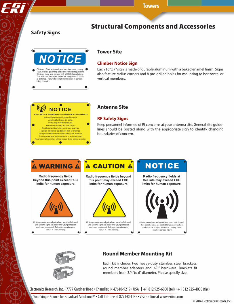
Round Member Mounting Kit
Each kit includes two heavy-duty stainless steel brackets, round member adapters and 3/8” hardware. Brackets fit members from 3/4”to 6” diameter. Please specify size.
Tower Site
Climber Notice SignEach 10” x 7” sign is made of durable aluminum with a baked enamel finish. Signs also feature radius corners and 8 pre-drilled holes for mounting to horizontal or vertical members.
Antenna Site
RF Safety SignsKeep personnel informed of Rf concerns at your antenna site. General site guide-lines should be posted along with the appropriate sign to identify changing boundaries of concern.
Safety Signs
Electronics Research, Inc. • 7777 Gardner Road • Chandler, IN 47610-9219 • USA +1 812 925-6000 (tel) • +1 812 925-4030 (fax)
Your Single Source for Broadcast Solutions™ • Call Toll-free at 877 ERI-LINE • Visit Online at www.eriinc.com© 2016 Electronics Research, Inc.
Towers

Structural Components and Accessories
INVISI-SHIELD®
Electrically Transparent Ice-ShieldRadial icing occurs when water droplets are large enough to fall from the atmosphere and freeze on objects near the ground. The frozen deposits form a clear ice shell on antenna and tower components. Radial ice conditions are typically very short in duration. The proceeding thaw releases segments of ice which fall or sail causing significant damage to antenna elements.
The antenna elements are particularly susceptible to falling ice. Radial ice has a unit weight of 56 pound per cubic foot and can cause significant damage to unprotected tower appurtenances. Steel ice shields can offer some degree of protection. But due to pattern distortion inherent to their construction the steel shields are placed at distances which diminish their ability to adequately protect the antenna. Some applications of a steel ice shield are prohibited due to the detracting effects it could have on neighboring antennas.
The ERI INVISI-SHIELD® is an electrically transparent ice shield. Utilizing custom fabricated materials and careful placement of connection components has resulted in a structure which has no perceptible effect on the antenna’s pattern. The INVISI-SHIELD® can be mounted directly over an antenna element. This close proximity allows the INVISI-SHIELD® to be significantly smaller while increasing protection when compared to a steel shield. The smaller size also results in less load to the tower. The electrical transparency of the INVISI-SHIELD® will permit installation between antenna bays in extreme icing conditions. The top edge of the INVISI-SHIELD® is permeated with a silicone grit. This material helps trap potential freezing rain on the shield reducing the potential of radial ice accumulation and detuning of the antenna element.
Features• Protection from falling ice • No perceptible pattern distortion• Can be mounted directly over each element• Reduces potential accumulation of radial ice• Convenient work platform
SpecificationsLoad Rating: 300 PSF uniform distribution 7,200 lbs. total capacity, High Impact
Resistance
Size: 6-feet x4-fet
Weight: 120 pounds
Wind Load: 320 pounds (50/33psf) (EIA RS-222-C)
Ac: 6.5 square feet projected area of discrete appurtenance
Ca: 2, discrete appurtenance force coefficient
CaAc: 13 square feet (ANSI/EIA-222-D)
Electronics Research, Inc. • 7777 Gardner Road • Chandler, IN 47610-9219 • USA +1 812 925-6000 (tel) • +1 812 925-4030 (fax)
Your Single Source for Broadcast Solutions™ • Call Toll-free at 877 ERI-LINE • Visit Online at www.eriinc.com© 2016 Electronics Research, Inc.
Towers