Embed Size (px)
Citation preview
Towards Prototype and Archetypes for Steel Diaphragm Innovation Initiative (SDII) project
B.W. Schafer March 2016
Objective The objective of this discussion is to examine existing work that may provide insights on appropriate archetypes for exploring the behavior and impact of conventional steel deck (typically topped with concrete) diaphragms in steel framed buildings. Analysis of available information for archetypes The Steel Deck Institute regularly updates its Diaphragm Design Manual (DDM) and this document includes full diaphragm examples as well as a significant amount of supplementary information relevant for steel deck diaphragm systems (Luttrell 2015). However, the DDM does not offer any direct building-scale archetypes; in addition, the bulk of DDM is focused on bare deck. (DDM Example 14 notes that diaphragm design in multi-story buildings with a shear core can result in large diaphragm forces and provides some insight on this case.) DDM provides strength tables for diaphragms with concrete fill following generic or proprietary fastener details. The strength of steel deck diaphragms with fill does not vary widely across the tables - for composite deck diaphragm (1-1/2 in. x 6 in., 2 in. x 12 in., 3 in. x 12 in.) with design thickness from 0.0295 in. (22 gauge) to 0.0598 in. (16 gauge), 36/4 fastener pattern, 2 ½ in. of normal weight concrete fill, spans of 5 to 13 ft, sidelap connections/span from 0 to 8, sidelap connectors of 5/8 in. spot welds, #10 fasteners, or a number of proprietary sidelaps, and perimeter connectors of 5/8 in. spot welds, #12’s, or considering a wide variety of perimeter fastening the nominal shear strength Sn = 5135-6535 plf. Diaphragm stiffness can also be calculated per DDM and is the summation of a fill and deck contribution, with G’=2380 kip/in. + deck contribution, where the deck contribution is small and on the order of 50 to 300 kip/in. depending on gauge, sidelap details, and joist spacing. In summary, DDM provides that a typical deck with normal weight concrete fill has a strength on the order of 5500 plf and stiffness of 2500 kip/in. The analysis of steel moment frame studies performed in the SAC joint venture (Krawinkler 2000) are some of the most comprehensive archetypes performed for steel buildings and formed the intellectual basis for much of the thinking around the performance of steel buildings over the last decade plus. Appendix B of Krawinkler (2000) describes in detail the SAC archetype buildings, which includes 3, 9, and 20-story buildings sited in Seattle, Los Angeles, and Boston and designed to pre-Northridge (prior to the 1994 Northridge) and post-Northridge (based on FEMA 267) standards. Nearly all the models are two-dimensional and all assume rigid diaphragm behavior. For a small set of the models three-dimensional frames were modeled, with the diaphragm assumed rigid and modeled with near-rigid struts. This influential study provides no insight on diaphragm behavior or interaction between the diaphragm and the frame, but provides most design details necessary for developing floor archetypes that match the developed systems. Formal use of building archetypes is a hallmark of the FEMA P695 (FEMA 2009) procedure for determining seismic response modification coefficients: R, Cd, and Wo. The role of diaphragms is conceptually recognized in the methodology and when influential, required to be considered (though no specific guidance is given on noting when this would be the case). Use of 3D models with diaphragm flexibility included is noted as a feature that gives a model with higher confidence, and this is rewarded in the procedure, but no examples given. FEMA P695 provides two extensive suites of examples with complete archetypes: wood light-frame and reinforced concrete moment frames, both assume rigid diaphragms. The reinforced concrete ordinary moment frame (OMF) archetypes cover: bay width (20 and
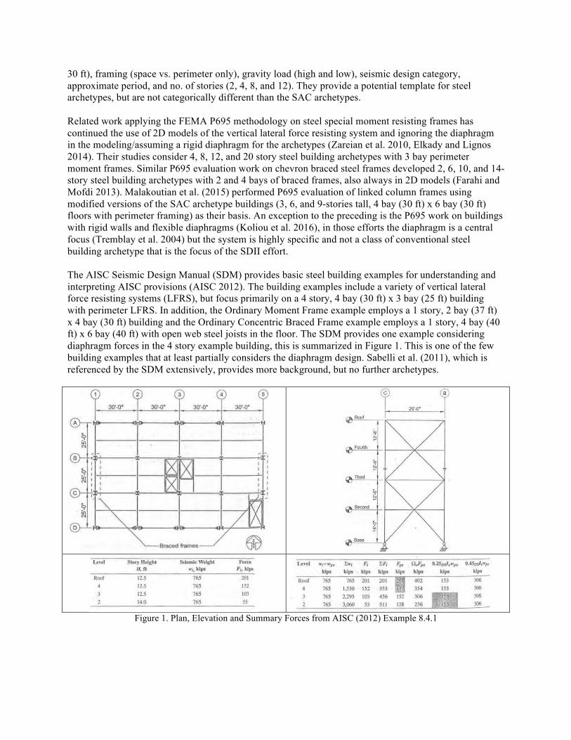
30 ft), framing (space vs. perimeter only), gravity load (high and low), seismic design category, approximate period, and no. of stories (2, 4, 8, and 12). They provide a potential template for steel archetypes, but are not categorically different than the SAC archetypes. Related work applying the FEMA P695 methodology on steel special moment resisting frames has continued the use of 2D models of the vertical lateral force resisting system and ignoring the diaphragm in the modeling/assuming a rigid diaphragm for the archetypes (Zareian et al. 2010, Elkady and Lignos 2014). Their studies consider 4, 8, 12, and 20 story steel building archetypes with 3 bay perimeter moment frames. Similar P695 evaluation work on chevron braced steel frames developed 2, 6, 10, and 14-story steel building archetypes with 2 and 4 bays of braced frames, also always in 2D models (Farahi and Mofdi 2013). Malakoutian et al. (2015) performed P695 evaluation of linked column frames using modified versions of the SAC archetype buildings (3, 6, and 9-stories tall, 4 bay (30 ft) x 6 bay (30 ft) floors with perimeter framing) as their basis. An exception to the preceding is the P695 work on buildings with rigid walls and flexible diaphragms (Koliou et al. 2016), in those efforts the diaphragm is a central focus (Tremblay et al. 2004) but the system is highly specific and not a class of conventional steel building archetype that is the focus of the SDII effort. The AISC Seismic Design Manual (SDM) provides basic steel building examples for understanding and interpreting AISC provisions (AISC 2012). The building examples include a variety of vertical lateral force resisting systems (LFRS), but focus primarily on a 4 story, 4 bay (30 ft) x 3 bay (25 ft) building with perimeter LFRS. In addition, the Ordinary Moment Frame example employs a 1 story, 2 bay (37 ft) x 4 bay (30 ft) building and the Ordinary Concentric Braced Frame example employs a 1 story, 4 bay (40 ft) x 6 bay (40 ft) with open web steel joists in the floor. The SDM provides one example considering diaphragm forces in the 4 story example building, this is summarized in Figure 1. This is one of the few building examples that at least partially considers the diaphragm design. Sabelli et al. (2011), which is referenced by the SDM extensively, provides more background, but no further archetypes.
Figure 1. Plan, Elevation and Summary Forces from AISC (2012) Example 8.4.1
Summary No suitable archetypes or prototypes exist in the open literature that focus on steel deck diaphragms for conventional steel buildings. Existing archetypes such as the SAC study could be extended. Three dimensional building analysis, with meaningful contributions from the diaphragm in terms of behavior, has not formed the basis for modern seismic standards in steel at this time. References: AISC (2012). Seismic Design Manual. American Institute of Steel Conctruction. Elkady, A. and D. G. Lignos. 2014. "Modeling of the Composite Action in Fully Restrained Beam-to-
Column Connections: Implications in the Seismic Design and Collapse Capacity of Steel Special Moment Frames." Earthquake Engineering and Structural Dynamics 43 (13): 1935-1954. doi:10.1002/eqe.2430.
Farahi, M. and M. Mofid. 2013. "On the Quantification of Seismic Performance Factors of Chevron Knee Bracings, in Steel Structures." Engineering Structures 46: 155-164. doi:10.1016/j.engstruct.2012.06.026.
FEMA (2009) Quantification of Building Seismic Performance Factors. Federal Emergency Management Association, FEMA P695, 421 pp.
Koliou, M., Filiatrault, A., Kelly, D. J., Lawson, J.. (2016). "Buildings with Rigid Walls and Flexible Roof Diaphragms. I: Evaluation of Current U.S. Seismic Provisions." Journal of Structural Engineering (United States) 142 (3). doi:10.1061/(ASCE)ST.1943-541X.0001438.
Krawinkler (2000) “State of the Art Report on Systems Performance of Steel Moment Frames Subject to Earthquake Ground Shaking.” Federal Emergency Management Agency, FEMA-355C, SAC Joint Venture.
Luttrell, L., Mattingly, J., Schultz, W., Sputo, T. (2015). Diaphragm Design Manual. Steel Deck Institute. 4th Ed. 405pp.
Malakoutian, M., J. W. Berman, P. Dusicka, and A. Lopes. 2015. "Quantification of Linked Column Frame Seismic Performance Factors for use in Seismic Design." Journal of Earthquake Engineering: 1-24. doi:10.1080/13632469.2015.1104750.
Sabelli, R., Sabol, T.A., Easterling, W.S. (2011). “Seismic Design of Composite Steel Deck and Concrete-filled Diaphragms: A Guide for Practicing Engineers.” NIST GCR 11-917-10, NEHRP Seismic Design Technical Brief No. 5, 38pp.
Tremblay, R., E. Martin, W. Yang, and C. A. Rogers. 2004. "Analysis, Testing and Design of Steel Roof Deck Diaphragms for Ductile Earthquake Resistance." Journal of Earthquake Engineering 8 (5): 775-816. doi:10.1142/S1363246904001699.
Zareian, F., Lignos, D. G., Krawinkler, H. (2010). "Evaluation of Seismic Collapse Performance of Steel Special Moment Resisting Frames using FEMA P695 (ATC-63) Methodology." ASCE Structures Congress 2010. doi:10.1061/41130(369)116.
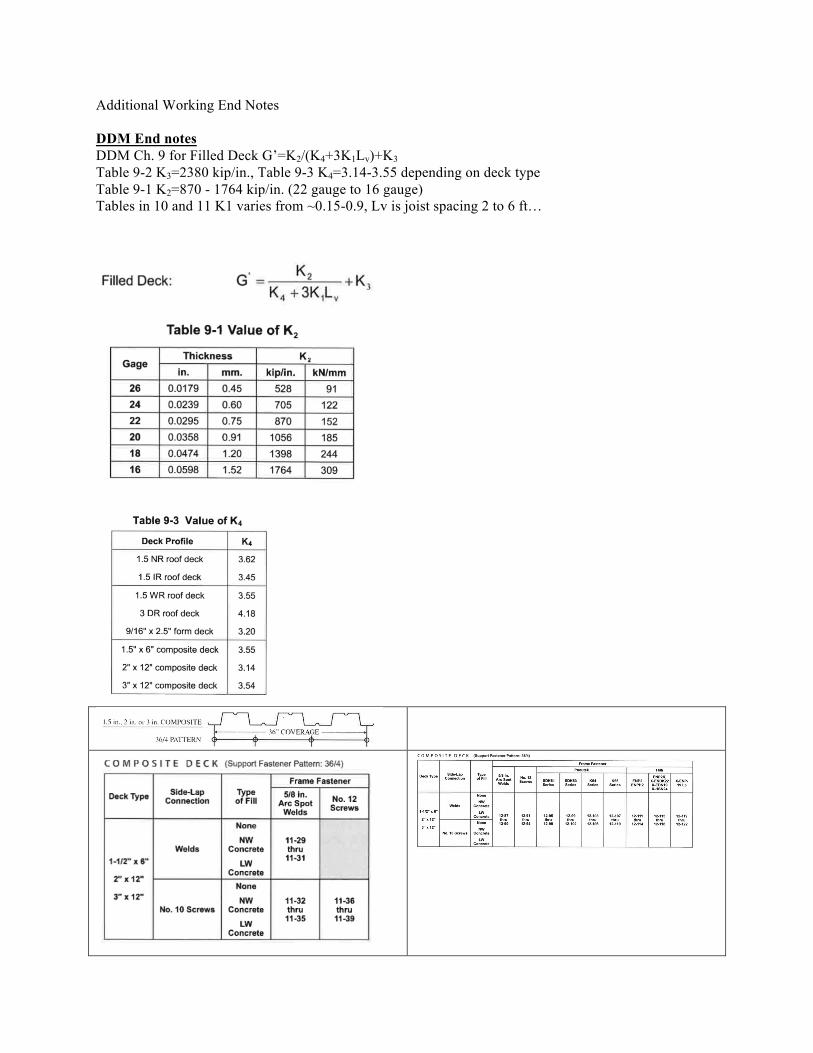
Additional Working End Notes DDM End notes DDM Ch. 9 for Filled Deck G’=K2/(K4+3K1Lv)+K3 Table 9-2 K3=2380 kip/in., Table 9-3 K4=3.14-3.55 depending on deck type Table 9-1 K2=870 - 1764 kip/in. (22 gauge to 16 gauge) Tables in 10 and 11 K1 varies from ~0.15-0.9, Lv is joist spacing 2 to 6 ft…
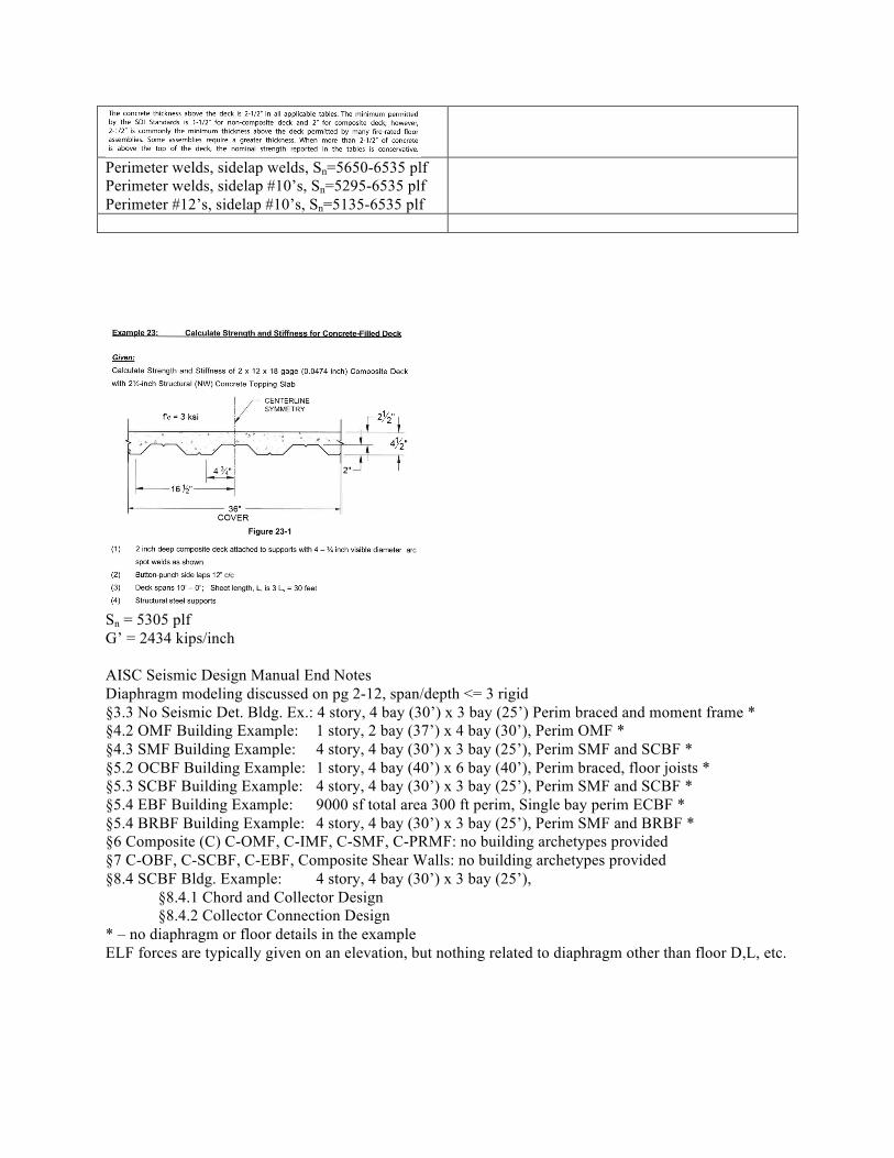
Perimeter welds, sidelap welds, Sn=5650-6535 plf Perimeter welds, sidelap #10’s, Sn=5295-6535 plf Perimeter #12’s, sidelap #10’s, Sn=5135-6535 plf
Sn = 5305 plf G’ = 2434 kips/inch AISC Seismic Design Manual End Notes Diaphragm modeling discussed on pg 2-12, span/depth <= 3 rigid §3.3 No Seismic Det. Bldg. Ex.: 4 story, 4 bay (30’) x 3 bay (25’) Perim braced and moment frame * §4.2 OMF Building Example: 1 story, 2 bay (37’) x 4 bay (30’), Perim OMF * §4.3 SMF Building Example: 4 story, 4 bay (30’) x 3 bay (25’), Perim SMF and SCBF * §5.2 OCBF Building Example: 1 story, 4 bay (40’) x 6 bay (40’), Perim braced, floor joists * §5.3 SCBF Building Example: 4 story, 4 bay (30’) x 3 bay (25’), Perim SMF and SCBF * §5.4 EBF Building Example: 9000 sf total area 300 ft perim, Single bay perim ECBF * §5.4 BRBF Building Example: 4 story, 4 bay (30’) x 3 bay (25’), Perim SMF and BRBF * §6 Composite (C) C-OMF, C-IMF, C-SMF, C-PRMF: no building archetypes provided §7 C-OBF, C-SCBF, C-EBF, Composite Shear Walls: no building archetypes provided §8.4 SCBF Bldg. Example: 4 story, 4 bay (30’) x 3 bay (25’),
§8.4.1 Chord and Collector Design §8.4.2 Collector Connection Design
* – no diaphragm or floor details in the example ELF forces are typically given on an elevation, but nothing related to diaphragm other than floor D,L, etc.