Embed Size (px)
Citation preview

Towards Dynamically-Favourable Quad-Rotor Aerial Robots
Paul Pounds, Robert Mahony, Joel GreshamAustralian National University, Canberra, Australia
[email protected], [email protected], [email protected]
Peter Corke, Jonathan RobertsCSIRO ICT Centre, Brisbane, Australia
[email protected], [email protected]
Abstract
This paper outlines progress towards realisingpractical quad-rotor robot helicopters and, inparticular, the Australian National University’s‘X-4 Flyer’ platform. Two challenges facing theX-4 are generating sufficient thrust and man-aging unstable dynamic behaviour. We ad-dress these issues with a rotor design techniquefor maximising thrust and the application of anovel rotor mast configuration. An aero-elasticblade design is described and its performanceresults are presented. A sprung teetering rotorhub that allows adjustment of the blade flap-ping characteristics and a quad-rotor dynamicmodel with blade flapping are introduced. Theuse of inverted rotors is shown to produce fa-vorable stability properties for the Mark II X-4Flyer.
1 Introduction
The X-4 Flyer design is based on the unique capabilitiesof four-rotor helicopters. Compared with conventionalhelicopters with single large rotors, quad-rotor craft canapproach much closer to an obstacle without fear ofrotor-strike. This makes the X-4 ideal for use indoors.The X-4 was conceived as an experimental platform foraerial robot research (fig. 1).
1.1 MotivationA benefit of electric quad-rotor robots is their mechanicalsimplicity. Hobby radio control (RC) helicopters exhibitfast dynamics due to their small rotor size. To compen-sate for this, the RC models employ Bell-Hillier stabilizerlinkages in the rotor control mechanism that act to slowthe natural dynamic response of the inherent unstableoscillatory mode in helicopter dynamics. This makes itpossible for humans to pilot the system. The X-4 has atotal of eight moving parts and does not require the out-lay in maintenance demanded by traditional helicopters.
Figure 1: X-4 Flyer Mark II.
We show that the stability issues can be addressed byincorporating the effects of rotor flapping into the X-4rotor and airframe design.
1.2 Previous Quad-Rotor SystemsOne of the earliest four rotor craft was the Breguet-Richet Gyroplane No. 1. The device could only at-tain an altitude of 1.5 m, flew for less than a minuteand needed a team of men to hold it steady. It wasthe first full-scale rotorcraft to lift under its own power[Leishman, 2002]. The quad-rotor Bell X-22 and Curtis-Wright X-19 were part of US government initiatives toexplore vertical takeoff and landing aircraft in the 1950s[Starostin, 2004]. The X-22 featured rotating ductedfans with thrust controlled by variable cyclic pitch. TheX-19 much more closely resembled contemporary quad-rotor craft, although the thrust generation system was aspecial type of radial lift propeller.
More recently, much work has been done on quad-rotor robots. A notable development is the popularDraganflyer RC toy. The Draganflyer is the archetypicalsmall-scale quad-rotor flyer and set the trend in current

four-rotor robots. Draganflyers have conventional rotororientation with hingeless rotor hubs and flexible rotorblades. To offset the difficulty in flying them, the flyershave piezo-electric gyros for pitch-roll stabilisation. Thesimplest Draganflyers have little payload, while othermodels can carry a small camera.
Other similar unmanned aerial vehicles (UAV) includethe Mesicopter, a micro-scale quad-rotor [Kroo et al,2000]; the Hoverbot [Borenstein, 2002]; and a ‘Quad-Rotor Tail-Sitter’, a flyer that takes off vertically thenrotates horizontally to fly on a partial wing [Young et al,2002]. With the exception of the Hoverbot, all of theserecent flyers have been fixed-pitch helicopters with fixedblade hubs.
1.3 Goals of Current DevelopmentCurrent work on the X-4 Flyer aims to solve two prob-lems: thrust and stability. Unlike their larger brethren,indoor helicopters have strictly limited rotor sizes, whileindoor quad-rotor flyers must have smaller rotors again.The power required to hover is linked to the size of therotor disc and so maximum lift and endurance will bedictated by the efficiency of the blade design. It is de-sirable to create rotors that produce the most thrustpossible.
Helicopters are intrinsically unstable. They exhibit os-cillating modes that are slow enough to be controlled byhumans in full-scale vehicles, but these are much fasterin small UAVs. The oscillatory mode is related to therotor moment speed-stability derivative. It is possible toconstruct helicopters without this effect and quad-rotorsare ideal for exploring this.
2 Rotors and Thrust
The rotors, motors and batteries determine the payloadand flight time performance of the flyer. The rotors,especially, influence the natural dynamics and power ef-ficiency. An approximate understanding of helicopterrotor performance can be obtained from the momentumtheory of rotors. The design of the X-4 rotors drawsupon the results of blade element theory for wings andhelicopters.
2.1 Rotor Aerodynamics and DesignRequirements
Momentum theory can be used to provide relationshipsbetween thrust, induced velocity and power in the rotor[Seddon, 1996, pp6-7]. Using energy conservation, it canbe shown that in hover:
T = 2ρAv2i (1)
and also:
Pi =T
32
√2ρA
(2)
where T is the thrust produced, ρ is the density of air, Ais the area of the rotor disc, vi is the induced air velocityat the rotor and Pi is the power induced in the air.
The Figure of Merit (F.M .) of the rotor is the ratioof power induced in the air and power in the rotor shaft:
F.M. =PiPs
(3)
This is like a rotor efficiency when calculating the theo-retical onboard power requirements.
Blade element theory is particularly useful for airfoiland rotor performance. The forces and moment devel-oped on a uniform wing are modelled by:
L = Cl12ρU2c (4)
D = Cd12ρU2c (5)
M = Cm12ρU2c2 (6)
where, for unit span, L is the lift produced, D is theprofile drag and M is the pitching moment [Honnery,2000, pp94,pp112]. U is the velocity of the wing throughthe air and c is the chord length. Cl, Cd and Cm arenon-dimensionalised coefficients of lift, drag and mo-ment, respectively. They are dependent upon the wing’sReynolds Number (RE), Mach number and angle of at-tack (AoA, or α).
The RE dictates the aerodynamic conditions in whichthe blade operates. The RE is a dimensionless valuethat can be used as a measure of dynamic similarity influid flows. In this case:
RE =ρUc
µ(7)
where here µ is the viscosity of air.For a rotor with angular velocity ω, the linear velocity
at each point along the rotor is proportional to the radialdistance from the rotor shaft: U = ωr. By integratinglift and drag along the length of the blade, equivalentrules may be produced for the entire rotor [Prouty, 2002,pp15]:
T = CT ρA (ωR)2 (8)
Q = CQρA (ωR)2R (9)
where T is the total thrust produced by the rotor, Q isthe rotor torque and R is the rotor radius. CT and CQare non-dimensionalised thrust and rotor torque coeffi-cients. Smaller rotors require higher speeds and morepower than larger rotors for the same thrust.
For a quad-rotor helicopter weighing 4 kg with a30 per cent control margin, each motor must produce12.7 N of thrust. In addition, the rotor radius can be

Figure 2: ANUX2 Polar Plot.
no greater than 0.165 m, due to the size of the robot,and so this will require 101.2 W of power induced inthe air. The rotational velocity should be less than800 rads−1 to avoid compressibility effects at the bladetip. The battery current limit of 22 A produces a max-imum 0.1749 Nm motor torque and hence a top shaftpower of 131 W. Therefore, the maximum theoreticalthrust is 15.1 N per motor (assuming F.M. = 1). Theactual rotor design F.M. must be no less than 0.77.
The rotor design has two elements: airfoil selectionand planform geometry. As the X-4 has fixed pitch, theblades are specifically optimised for hovering conditions.The aim of airfoil design is to maximise Cl and minimiseCd and Cm in the operating region of the rotor. The aimof the planform design is to set the blade dimensions soas to keep the relative AoA and RE at the ideal valuesfor the airfoil as the linear velocity increases with radius.
2.2 Airfoil DesignAt the low REs in which the blades operate (order of100,000), very thin blade profiles at low angles of attackperform best. The DFmod3 airfoil, designed by MarkDrela for MIT’s four-rotor flyer [Drela, 2003], operatesat RE = 70, 000 and has a thickness to chord ratio of3.5 per cent. However, blades using this airfoil could notbe aerodynamically scaled to suit the X-4. Thin bladesare difficult to make rigid and their sharp leading edgescan cause stalling at angles as low as 10.
Changing the angle of attack alters the values of thenon-dimensionalised coefficients, as shown by the famil-iar polar plot (fig. 2). Increasing AoA increases Cl, upto the stall angle. High-lift airfoils tend to exhibit largepitching moments. The moment is produced by the cen-tre of lift being forward of the airfoil’s geometric centre.The greater the lift produced, the greater the moment.
Figure 3: DFmod3 and ANUX2 Airfoil Sections, Topand Bottom.
This causes a positive-feedback, twisting effect that canlead to exceptionally thin wings, such as low-RE rotorblades, suffering severe torsional deformation.
A custom airfoil, the ANUX2, was designed using theX-foil program by Drela [Drela, 2004]. The airfoil wasmade twice as thick in the body as the DFmod3, witha broader nose and flat bottom surface (fig. 3). Thecentres of camber and thickness were also moved aft toreduce Cm. The ANUX2 was designed to operate atRE = 94, 000 with an ideal AoA of 4.4. In simula-tion the ANUX2 showed superior performance to simi-lar high-lift, low speed airfoils such as the DFmod3, VR8and MA409sm [NASG, 2004]. It has several favourableproperties:
• Good optimal-AoA Cl of 0.9
• Insensitive to small changes in AoA
• Good performance over the operating RE range
• Improved stiffness from 7 per cent thickness ratioand increased mass at leading and trailing edges.
2.3 Planform Design for BladeAero-elasticity
Each airfoil performs best at a specific RE and AoA. Asthe linear velocity changes with radius, so too must thechord length and θ vary to maintain these conditions.To keep RE constant for a given angular velocity, c · rmust be constant.
The velocity of the air down through the rotor reducesthe apparent AoA of the blades. The angle between therelative wind and the hovering blade velocity is the inflowangle, φ:
α = θ − φ (10)
φ =viωr
(11)
where θ is the geometric angle of the blades. To maintainthe design AoA, the blade angle must twist such that:
θ = αideal +viωr
(12)
These are hyperbolic distributions in r - known as ‘idealchord’ and ‘ideal pitch’. Although difficult to implementin full-scale helicopters, the X-4 can readily apply them.
Design for aerodynamics is complicated by bladetwisting. The moment on the blades causes them totwist until either the elastic torque equals the blade pitchmoment or the blade stalls. The twist along the bladeis non-uniform, with the greatest deflection occurring atthe blade tip. It is reasonable to only be concerned withthe outboard third of the rotor, as this is where the ma-jority of the thrust is developed. The geometric bladeangle can be set so that the tip will twist up to the cor-rect pitch.
The motor-rotor system consists of a set of dynamicinteractions that reach equilibrium governed by the cur-rent available to drive the motor. An iterative simulatorwas coded in Matlab to find steady-states and explorethe effects of design changes. The simulator uses bladeelement theory to determine the thrust, drag and mo-ment produced at each radius station. Using the simu-lator, it is possible to test a range of reasonable param-eter settings to find the ideal geometry. A similar, non-elastic method was used to design rotors for the HARVeetilt-rotor developed at the Fulton School of Engineering[Wells, 2004].
The simulator found the optimal geometry to be atip chord of 10.4 mm, and tip pitch of 3.9, with idealpitch and chord. The simulator calculated a total thrustof 13.87 N at 764 rads−1. The length of the blade is165.1 mm (from the shaft centre), with the hub clampat 40 mm. For the production blade, the tip angle wasreduced to 3.1 to allow for any unexpected flex or angu-lar error; simulation showed that variations of as much as2 in mounting pitch error could still produce sufficientthrust. This was favourable as the screw-down mountingbracket used was not accurate to more than 0.5.
2.4 Motors and PowerThe motor-speed servo systems selected were Jeti Phasor30-3 brushless motors, along with their companion Jeti40-3P electronic speed controllers (ESCs). A particularadvantage of this motor is the high torque performancethat allows for direct drive of the rotors, rather thanrequiring gearing. The motors can safely pass more than300 W at a maximum of 35 A.
The batteries used are Kokam 1500 mAh high-discharge cells. Each cell is nominally rated at 3.7 Vand can deliver 12 A constantly, or 15 A for short bursts.The batteries are connected to a power bus of eight par-allel sets of four cells in series; that is, 14.8 V nominalvoltage and current draw of 24 A per motor.
2.5 Performance ResultsAs manufactured (fig. 4), the rotors produce 13.7 N ofthrust on a test-rig, comparing favourably with the sim-
Figure 4: ANUX2 Blade With Ideal Chord and Twist.
ulator prediction. The current draw was 22 A at 12 V atfull speed. This gives the X-4 a theoretical endurance ofmore than eight minutes at constant full speed. At con-stant hovering speed, this could be extended to almost11 minutes.
3 Dynamics and Stability
Most treatments of quad-rotor dynamics do not includeblade flapping. In fact, all rotors flap to some degree dueto blade flexibility. Thin plastic rotors such as those usedin the Draganflyer are particularly prone to this effect.We can model the flyer behaviour using the dynamics ofa rigid-rotor quad-rotor helicopter modified with addi-tional flapping dynamics.
3.1 Rigid Body Dynamic ModelA basic flyer dynamic model [Pounds et al, 2002] ismodified for articulated rotors by implementing a modelof the rotor flapping and generalised rotor force andtorque components: I= Ex, Ey, Ez is a right-handinertial frame where z is in the direction of gravityand ξ = (x, y, z) is the origin of the body fixed frameA =Ea1 , Ea2 , Ea3. A is related to I by the rotation ma-trix R : A → I. V and Ω are the linear and angularvelocities of the frame in A (fig. 5).
The revised equations are:
ξ = RV (13)
mV = −mΩ× V +mgRT e3 +∑
N,S,E,W
Ti (14)
R = R · sk (Ω) (15)
IΩ = −Ω× IΩ +∑
N,S,E,W
[Qi +Mi] (16)
ωi = −1τ
+K
τui −Qi (17)
Ti = CT ρAR2ω2
i
−sa1si
ca1sisb1si
cb1sica1si
(18)
Qi = CQρAR3ωi|ωi|e3 (19)
where m and I are the mass and rotational inertia of theflyer, g is acceleration due to gravity, τ and K are themotor time constant and system gain, a1si and b1si are

Figure 5: Flapping Quad-Rotor Free-body Diagram.
the longitudinal and lateral harmonic flapping angles ofthe ith rotor and Mi is the moment due to the thrust ofthe ith rotor.
Rotors are indexed by their corresponding compass di-rections: North, South, East and West (NSEW ), whereN indicates the front rotor. sk(x) is the skew-symmetricmatrix such that sk(a)b = a×b for vectors in <3. The sxand cx notations represent sinx and cosx respectively.
The rotation matrix R is constructed with the yaw-pitch-roll, η = (φ, θ, ψ) Euler angles:
R =
cθcφ sψsθcφ − cψsφ cψsθcφ + sψsφcθsφ sψsθsφ + cψcφ cψsθsφ − sψcφ−sθ sψcθ cψcθ
(20)
3.2 Blade Flapping Model
Prouty provides a generalised model for the flapping be-haviour that can be adapted to the X-4 [Prouty, 2002,pp469]. The angles are described as functions of the heli-copter’s forward velocity and are obtained by simultane-ously solving the constant and sinusoidal components ofthe blade centrifugal-aerodynamic-static weight momentsystem. For the X-4 it is presumed that the craft is mov-ing in pure translation with no velocity component at therotors due to yaw rotation. Application of the equationsto more general flyer motion is straightforward and notdone here. The flapping angle solutions for fixed pitchrotors subject to linear motion, adapted from Prouty,
and Coleman’s inflow model [Chen, 1990], are:
a1si = 1
1−µ2
i2
µi (4θt − 2λi)
+12( e
R )γ(1− e
R )3(
1+µ4
i4
) × 43
(CT /σ
23
µiγ
a
1+ 32
eR
+ µi
)(21)
b1si = 1
1+µ2
i2
43
(CT /σ
23
µiγ
a
1+ 32
eR
+ µi
)+
12( eR )
γ(1− eR )3
(1−
µ4i4
) × µi (4θt − 2λi) (22)
where e is the hinge offset, µi is the advance ratio ofthe ith rotor, a is the polar lift slope and γ is the LockNumber:
γ =ρacr4
Ib(23)
where Ib is the rotational inertia of the blade about theflapping hinge.
The components of the flapping angles produced bythe craft’s pitch and roll rates are added to those offorward flight:
a1si = . . .+
− 16γ ( q
ω )(1− e
R )2 +(pω
)1− µ2
i
2
+
12γ
eR
(1− eR )3
[− 16
γ ( pω )
(1− eR )2 −
(qω
)]1− µ4
i
4
(24)
b1si = . . .+
− 16γ ( p
ω )(1− e
R )2 +(pω
)1− µ2
i
2
+
12γ
eR
(1− eR )3
[− 16
γ ( qω )
(1− eR )2 −
(pω
)]1− µ4
i
4
(25)
3.3 Rotor MomentsThe moments produced by the rotor flapping are com-prised of two components - the rotor hub stiffness andthe thrust vector acting around a displacement from thevehicle’s centre of gravity:
Mi =dMM
da1sia1si +Di × Ti (26)
where Di is the rotor displacement from the flyer cen-tre of mass:
DN =(
0 d h)
(27)
DS =(
0 −d h)
(28)
DE =(d 0 h
)(29)
DW =(−d 0 h
)(30)
d is the arm length of the flyer and h is the height of therotors above the CoG.
The rotor stiffness, dMM/da1si, is due to physical stiff-ness of the rotor and centrifugal forces derived from theeffective hinge offset e of the rotor. Typically, the physi-cal stiffness of a rotor is ignored in flyer analysis and the

rotor stiffness is modelled purely as a centrifugal term.The rotor stiffness is given by Prouty as:
dMM
da1si=
34
( eR
) AbρR (ωR)2 aγ
(31)
In the proposed rotor design the effective hinge off-set is replaced by a physical torsional spring attached toa teetering rotor. The virtual hinge offset can be cal-culated from the spring constant and blade certripetalbehaviour. The moment about the blade flapping hingeis given by:
MC.F. = ω2β
(Ib +
eMb
g
)(32)
where β is the blade flapping angle and Mb is the staticmoment of the blade about the hinge [Prouty, 2002].
For a torsional spring of stiffness k0 mounted at theteetering hub:
Msprg = ω2βIb + βk0 (33)
It can be seen that the spring will behave the same asa hinge offset, such that:
eeqv =k0g
ω2Ib(34)
The spring is not a perfect offset replacement, as theapparent offset will change with changing ω. However,around hover (near constant rotor speed) the spring willreproduce favourable hinge offset behaviour, allowingstandard helicopter formulae to be applied.
3.4 Stability AnalysisBy using the adapted rotor model and making some sim-plifications particular to the X-4, it is possible to emulatethe longitudinal dynamic stability analysis by Proutyfor near-hover conditions. The essential assumptions arethat the advance ratio is small, the motion is constrainedto pitch and X translation, the flapping angles are smalland the flyer is applying the same thrust at each motor.The differential equations are given in terms of stabilityderivatives in X and q:
−mX +∂X
∂XX +
∂X
∂qq −mgΘ = 0 (35)
∂M
∂XX − Iyy q +
∂M
∂qq = 0 (36)
Using Routh’s Discriminant (R.D.), the stability ofthe system can be assessed for varying physical parame-ters. The characteristic equation is given by:
s3 −(
1m
∂X
∂X+
1Iyy
∂M
∂q
)s2 +
g
Iyy
∂M
∂X= 0 (37)
For a cubic polynomial As3 + Bs2 + Cs + D = 0, thediscriminant is R.D. = BC −AD. In this case:
R.D. = − g
Iyy
∂M
∂X(38)
For the X-4, the stability derivatives are:
∂M
∂X= 4× ∂M
∂a1s
∂a1s
∂µ
∂µ
∂X− ∂X
∂Xh (39)
∂X
∂X= 4×−CT ρA (ωR)2
∂a1s
∂µ
∂µ
∂X(40)
∂a1s
∂µ= 4θt − 2λi (41)
∂µ
∂X=
1ωr
(42)
The discriminant and coefficients provide useful infor-mation about the changing stability of the system withvarying parameters [Prouty, 2002, pp602]. If R.D. ispositive, there will not be any unstable oscillation. ZeroR.D. implies neutral stability. If all characteristic equa-tion coefficients were positive non-zero there would be nopure divergence; this is not achievable because C = 0. IfD is zero, the system will be neutral with no oscillation.It would be ideal to set up the flyer in such a way thatthis final condition can be achieved.
By observation, it can be seen that neutral stabilitycan be achieved by setting ∂M/∂X = 0. However, thisrequires that the rotor stiffness and thrust vector off-set moments cancel and would be difficult to achievein practice. Setting the derivative sufficiently negativeensures that the system is non-oscillatory - the helicopterwill have a single unstable pole in the right-half planewhich can be more easily corrected for by a human orautopilot.
For the X-4, ∂X/∂X is always negative, while∂M/∂a1s · ∂a1s/∂µ is always positive. For pure diver-gence, the geometry must satisfy:
−CT ρA (ωR)2 h >34
( eR
) AbρR (ωR)2 aγ
(43)
This can only be true if h < 0. Physically, this meansthat the centre of gravity (CoG) must be above the rotorplane. The idea of inverting the rotor not new: it hasbeen applied in the past in De Lackner’s HZ-1 [Starostin,2004] and has similarities with the well-known Hiller Fly-ing Platform [Starostin, 2004] and Charles H. Zimmer-man’s ‘whirligig’ [NASM, 2004]. The Mesicopter alsohas an inverted rotor configuration, but fixed rotors; itwas found that increasing CoG distance from the rotorplane increases damping but does not benefit the natu-ral frequency [Kroo et al, 2000]. In all these cases therigid (or near-rigid) rotors would produce small or zero
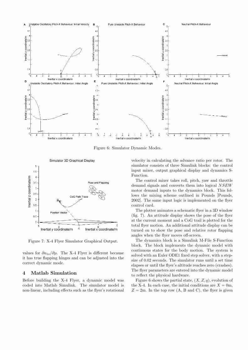
Figure 6: Simulator Dynamic Modes.
Figure 7: X-4 Flyer Simulator Graphical Output.
values for ∂a1s/∂µ. The X-4 Flyer is different becauseit has true flapping hinges and can be adjusted into thecorrect dynamic mode.
4 Matlab Simulation
Before building the X-4 Flyer, a dynamic model wascoded into Matlab Simulink. The simulator model isnon-linear, including effects such as the flyer’s rotational
velocity in calculating the advance ratio per rotor. Thesimulator consists of three Simulink blocks: the controlinput mixer, output graphical display and dynamics S-Function.
The control mixer takes roll, pitch, yaw and throttledemand signals and converts them into logical NSEWmotor demand inputs to the dynamics block. This fol-lows the mixing scheme outlined in Pounds [Pounds,2002]. The same input logic is implemented on the flyercontrol card.
The plotter animates a schematic flyer in a 3D window(fig. 7). An attitude display shows the pose of the flyerat the current moment and a CoG trail is plotted for thetotal flyer motion. An additional attitude display can beturned on to show the pose and relative rotor flappingangles when the flyer moves off-screen.
The dynamics block is a Simulink M-File S-Functionblock. The block implements the dynamic model withcontinuous states for the body motion. The system issolved with an Euler ODE1 fixed step solver, with a step-size of 0.02 seconds. The simulator runs until a set timeelapses or until the flyer’s altitude reaches zero (crashes).The flyer parameters are entered into the dynamic modelto reflect the physical hardware.
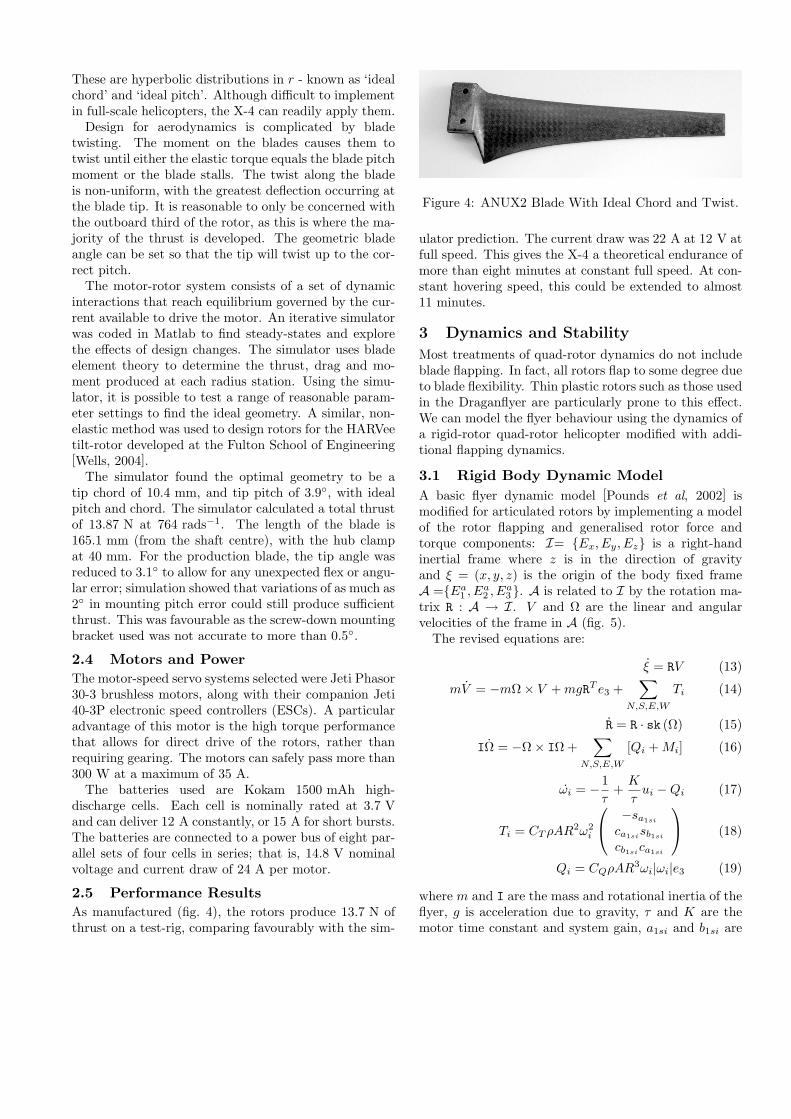
Figure 6 shows the partial state, (X,Z, q), evolution ofthe X-4. In each case, the initial conditions are X = 0m,Z = 2m. In the top row (A, B and C), the flyer is given
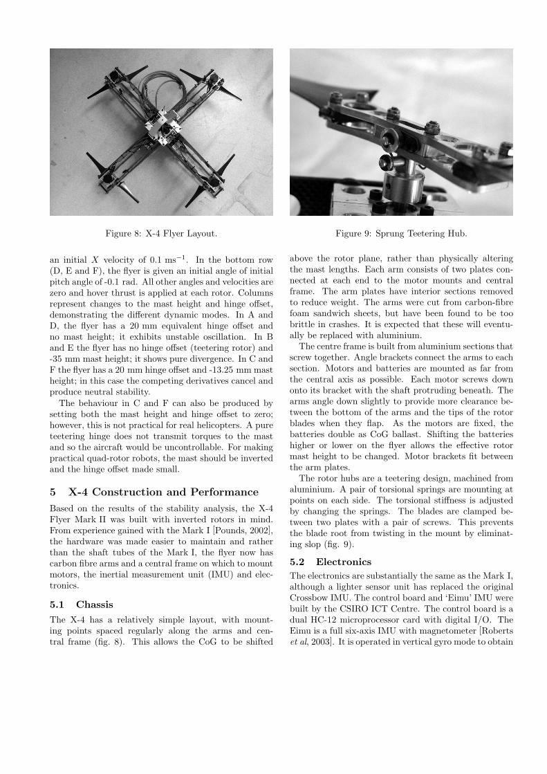
Figure 8: X-4 Flyer Layout.
an initial X velocity of 0.1 ms−1. In the bottom row(D, E and F), the flyer is given an initial angle of initialpitch angle of -0.1 rad. All other angles and velocities arezero and hover thrust is applied at each rotor. Columnsrepresent changes to the mast height and hinge offset,demonstrating the different dynamic modes. In A andD, the flyer has a 20 mm equivalent hinge offset andno mast height; it exhibits unstable oscillation. In Band E the flyer has no hinge offset (teetering rotor) and-35 mm mast height; it shows pure divergence. In C andF the flyer has a 20 mm hinge offset and -13.25 mm mastheight; in this case the competing derivatives cancel andproduce neutral stability.
The behaviour in C and F can also be produced bysetting both the mast height and hinge offset to zero;however, this is not practical for real helicopters. A pureteetering hinge does not transmit torques to the mastand so the aircraft would be uncontrollable. For makingpractical quad-rotor robots, the mast should be invertedand the hinge offset made small.
5 X-4 Construction and Performance
Based on the results of the stability analysis, the X-4Flyer Mark II was built with inverted rotors in mind.From experience gained with the Mark I [Pounds, 2002],the hardware was made easier to maintain and ratherthan the shaft tubes of the Mark I, the flyer now hascarbon fibre arms and a central frame on which to mountmotors, the inertial measurement unit (IMU) and elec-tronics.
5.1 ChassisThe X-4 has a relatively simple layout, with mount-ing points spaced regularly along the arms and cen-tral frame (fig. 8). This allows the CoG to be shifted
Figure 9: Sprung Teetering Hub.
above the rotor plane, rather than physically alteringthe mast lengths. Each arm consists of two plates con-nected at each end to the motor mounts and centralframe. The arm plates have interior sections removedto reduce weight. The arms were cut from carbon-fibrefoam sandwich sheets, but have been found to be toobrittle in crashes. It is expected that these will eventu-ally be replaced with aluminium.
The centre frame is built from aluminium sections thatscrew together. Angle brackets connect the arms to eachsection. Motors and batteries are mounted as far fromthe central axis as possible. Each motor screws downonto its bracket with the shaft protruding beneath. Thearms angle down slightly to provide more clearance be-tween the bottom of the arms and the tips of the rotorblades when they flap. As the motors are fixed, thebatteries double as CoG ballast. Shifting the batterieshigher or lower on the flyer allows the effective rotormast height to be changed. Motor brackets fit betweenthe arm plates.
The rotor hubs are a teetering design, machined fromaluminium. A pair of torsional springs are mounting atpoints on each side. The torsional stiffness is adjustedby changing the springs. The blades are clamped be-tween two plates with a pair of screws. This preventsthe blade root from twisting in the mount by eliminat-ing slop (fig. 9).
5.2 ElectronicsThe electronics are substantially the same as the Mark I,although a lighter sensor unit has replaced the originalCrossbow IMU. The control board and ‘Eimu’ IMU werebuilt by the CSIRO ICT Centre. The control board is adual HC-12 microprocessor card with digital I/O. TheEimu is a full six-axis IMU with magnetometer [Robertset al, 2003]. It is operated in vertical gyro mode to obtain

Figure 10: Logged Tethered Pitch Data Power SpectralDensity.
inertial frame reference angles. There is room inside theframe for mounting the Eimu as close to the centre ofgravity as possible.
Rubber grommets isolate the IMU from vibrationstransmitted along the frame. Additional grommets alsoisolate the frame from the motors. Testing of the flyeron a tethered mount at full rotor speed showed that theIMU is relatively free from vibration. The power spec-tral density shows that the Eimu’s filters do not passany high-frequency noise (fig. 10). The Mark I flyer wasespecially susceptible to resonance in the pitch direction.
Unlike the Mark I, the Mark II incorporates simpleonboard proportional-integral-derivative control. Theprevious iteration used a slow, off-board control systemconnected to the flyer by a tether. It is anticipated thatthe convenient aerodynamics of the X-4 will make so-phisticated control unnecessary. In conjunction with on-board power, this will allow the flyer to be entirely self-contained.
6 Conclusion
The two key challenges facing the development of theAustralian National University’s X-4 Flyer were thrustgeneration and dynamic stability. The thrust genera-tion problem was solved by developing an efficient ro-tor matched to the motor speed, torque and materialsstrength. Although free-flight experimental results arenot yet available, simulation in Matlab shows that theinverted rotor configuration is beneficial to quad-rotorflyers. The X-4 Flyer has been assembled and demon-strated significant thrust. It is expected that it will ex-hibit slow unstable dynamics and be straight-forward tocontrol by a human or autopilot.
7 Acknowledgements
This work was supported by Discovery grant DP0342849.The authors would like to thank
• The CSIRO ICT group for hosting and laboratoryspace; in particular, Leslie Overs, Stephen Brosnanand Dirk Stauffacher for their help with the flyercode and electronics.
• Joel McDonald for his work with flyer data systems.
• Mark Drela for his assistance with airfoil design
References
[Borenstein, 2002] J. Borenstein. Hoverbot: An Electri-cally Powered Flying Robot. Unpublished paper, 2002.
[Chen, 1990] R. T. N. Chen. A Survey of NonuniformInflow Models for Rotorcraft Flight Dynamics andControl Applications. In VERTICA, Vol. 14, No. 2,1990.
[Drela, 2003] M. Drela. MIT 16.82 Flight Vehicle Engi-neering Course Demonstrator.http://student.mit.edu/catalog/m16b.html, 2004.
[Drela, 2004] M. Drela. X-Foil Subsonic Airfoil Devel-opment System.http://raphael.mit.edu/xfoil/, August 2004.
[Honnery, 2000] D. Honnery. Introduction to the Theoryof Flight. Gracie Press, Northcote, Victoria, 2000.
[Kroo et al, 2000] I. Kroo, F. Prinz, M. Shantz, P. Kunz,G. Fay, S. Cheng, T. Fabian, C. Partridge. The Mesi-copter: A Miniature Rotorcraft Concept Phase II In-terim Report. Stanford University, July 2000.
[Leishman, 2002] J. G. Leishman. The Breguet-RichetQuad-Rotor Helicopter of 1907.www.enae.umd.edu/AGRC/Aero/Breguet.pdf, May2002.
[NASG, 2004] Nihon University Aero Student Group.Airfoil Database. www.nasg.com/afdb/index-e.phtml,August 2004.
[NASM, 2004] National Air and Space Museum.Zimmerman Flying Platform ”Whirligig”.www.nasm.si.edu/research/aero/aircraft/zimmerman.htm, August 2004.
[Pounds, 2002] P. Pounds. Design, Fabrication and Con-trol of a Four-Rotor Aerial Robot. Australian NationalUniversity undergraduate thesis, Canberra, Australia,2002.
[Pounds et al, 2002] P. Pounds, R. Mahony, P. Hynesand J. Roberts. Design of a Four-Rotor Aerial Robot.In Proc. of Australasian Conference on Robotics andAutomation, Auckland, New Zealand, 2002.

[Prouty, 2002] R. W. Prouty. Helicopter Performance,Stability, and Control. Krieger Publishing Company,2002, reprint with additions, original edition 1986.
[Roberts et al, 2003] J.M. Roberts and P.I. Corke andG. Buskey. Low-Cost Flight Control System for a sSmall Autonomous Helicopter. In Proceedings of IEEEInt. Conf. on Robotics and Automation, Taipai, 2003.
[Starostin, 2004] M. Starostin. All the World’s Rotor-craft. http://avia.russian.ee, August 2004.
[Seddon, 1996] J. Seddon. Basic Helicopter Aerodynam-ics. Blackwell Science, Osney Mead, Oxford, 1996.
[Wells, 2004] V. Wells. Propeller.www.eas.asu.edu/~harvee/papers/propeller.pdf,August 2004.
[Young et al, 2002] L.A. Young, E.W. Aiken, J.L. John-son, R. Demblewski, J. Andrews, J. Klem. New Con-cepts and Perspectives on Micro-Rotorcraft and SmallAutonomous Rotary-Wing Vehicles. Ames ResearchCenter, Moffett Field, California, 2002.