Embed Size (px)
Citation preview
PAUL SCHERRER INSTITUT
J
(&QW%-fl(V-o^
ribziK^z-N-^n
Second Symposium
Towards Clean Diesel Engines
DiSTEiruTiOH :-T;T^r::-;rrr A
DlV:.)):■ \i-.i:a. Ur/'irri.c-;
Book of Abstracts
Paul Scherrer Institute and
Swiss Federal Institute of Technology
Switzerland, May 14th and 15th, 1998
19980710 120
Foreword
In the next decades Diesel engines should gain more importance in the automobile
market. A larger proportion of Diesel powered vehicles will help to restore the C02
balance significantly. Possibly, other concepts like fuel cells in combination with
electromotors, for example, could solve the C02 problem even more thoroughly; but it
is unrealistic to expect that the whole of the fleet of vehicles could be replaced by such
alternatives in a short time. Continued development of efficient and clean Diesel
engines remains the best speditive route towards better co-existence of transport and
environment.
Particulates and NO emissions from Diesel engines are certainly a major concern. To
solve such problems, all aspects about and around the engine have to be reviewed.
Consequently, many disciplines will have to be engaged if the task is to be completed
reasonably quickly. Cross-disciplinary work does not evolve by itself, but needs to be
established and then encouraged. The first symposium "Towards Clean Diesel Engines"
at Nijmegen in 1996 started this process; we would like to see this continue during the
present meeting.
The combustion group of Paul Scherrer Institut is delighted to welcome you to the
second symposium "Towards Clean Diesel Engines." We hope that our meeting will be
profitable to you. We express our thanks to all who made or will make contributions to
its success.
April 6,1998
T. Gerber
Acknowledgements
The organizing committee would like to thank the following organisations and companies for their generous support:
Stichting voor de Technische Wetenschappen, Utrecht, NL
Lambiotte & Cie, S. A., Brussels, B
Erdöl-Vereinigung, Zürich, CH
ERO, European Research Office, United States Army, London, GB
Federal Office of Energy, Bern, CH
TOWARDS CLEAN DIESEL ENGINES
Local Organizing Committee
Thomas Gerber Reaktionsanalysen Paul Scherrer Institut Fax: +41 56 310 21 99 CH -5232 Villigen PSI E-mail: [email protected]
Konstantinos Boulouchos Inst, für Energietechnik LW ETH Zentrum, MLK 21 Fax: + 411 632 11 02 CH-8092 Zürich E-mail: [email protected]
Mrs. Ursula Grütter Paul Scherrer Institut Tel: +41 56 310 29 19, Fax: 41 56 310 21 99 CH -5232 Villigen PSI E-mail: [email protected]
List of Contributions Invited Lectures
Technical Approaches Geared Towards Complying With Future Emission Standards A Challenge For Simulation and Diagnosis Methods
Klaus Binder Development Commercial Vehicle Engines Daimler-Benz AG, Stuttgart, D
Research Issues in Direct-Injection Diesel Engines
C. Arcoumanis Dept. of Mechanical Engineering Imperial College of Science, Technology & Medicine, London, UK
Modeling of Fuel Sprays in Diesel Engines F. X. Tanner I.C. Engines and Combustion Laboratory ETH, Zürich, CH
Optical Diagnostics in Diesel Sprays
Visualisations of High-Pressure Sprays and their Combustion
E. Schünemann, A. Leipertz Lehrstuhl fur Techn. Thermodynamik Friedrich-Alexander-Universität Erlangen-Nürnberg, D
T. Baritaud, D. Verhoeven Institut Fransais du Petrole Rueil-Malmaison, F
Pitfalls and Promises ofLIF Diagnostics in Diesel Engines
N. Dam Applied Physics (Diesel Lab) University of Nijmegen, NL
Chemical Kinetics and Key Processes in Hydrocarbon Containing Flames
Detailed Chemical Modeling of Pollutant Formation in DI-Diesel Engines
J. Vandooren Universite Catholique de Louvain, B
H. Barths, N. Peters Institut für Technische Mechanik RWTH, Aachen, D
Diesel Combustion Study by Optical Diagnostics
B. M. Vaglieco Fluid-Dynamics & Combustion Div. Istituto Motori, CNR-Napoli, I
Diesel Fuel - Balancing Environmental Requirements and Customer Needs
D. Britton Shell International Petroleum Company London, UK
Environmental Aspects of Fine Particles and Soot
A. Fischer-Riedmann EMPA, Dübendorf, CH
Diesel Particulate Filter: The Most Promising Technology for Achieving a Significant Abatement of Diesel Particulate Emissions in Mass and Number
J. Lemaire, W. Mustel Rhodia - Automotive Emissions Control Courbevoie, F
List of Contributions (continued)
Contributed Papers - Posters
Numerical and Experimental Studies of High- Pressure Diesel Fuel Injection
M. Islam, E. Blümcke Audi AG, Ingolstadt, D
Chemical Kinetic Simulations ofNOx Reduction in Combustion of Heavy Fuel Oil with Diesel Exhaust Gas - A Case Study Using the Flow Tube Approach
T. Norström et al. Äbo Akademi University Turku, SF
Improved Modelling for Key Subprocesses in Diesel Engine Combustion Simulations
G. Weisser, F.X. Tanner, T. Gradinger, K Boulouchos I.C. Engines and Combustion Laboratory ETH, Zürich, CH
Combustion and Pollutant Formation in DI Diesel Engines Equipped with Common-Rail Fuel Injection Systems
K. Boulouchos, L. Jäger, R. Schubiger, H. Stebler, M.K. Eberle I.C. Engines and Combustion Laboratory ETH, Zürich, CH
Liquid and Vapor Distribution of a Diesel Spray During Mixture Formation
M. Astarita, F.E. Corcione, G. Mazziotti, B.M. Vaglieco Istituto Motori, CNR-Napoli, I
A Computational Study of the Effect of Nozzle Geometry on Nitric Oxide Formation under Medium-Size Diesel Engine Conditions
G. Weisser, F.X. Tanner, K Boulouchos I.C. Engines and Combustion Laboratory ETH, Zürich, CH
LIF Diagnostics of NO in a Two-Stroke Diesel Engine
G.G.M. Stoffels, C.M.I. Spaanjaars, N. Dam, W.L. Meerts, J.J. ter Meulen Applied Physics (Diesel Lab) University of Nijmegen, NL
Laser Diagnostics in a 6-Cylinder 11.6 Liter DAF Diesel Engine
E.J. van den Boom, G.G.M. Stoffels, C.M.I. Spaanjaars, N. Dam, W.L. Meerts, J.J. ter Meulen Applied Physics (Diesel Lab) University of Nijmegen, NL
A Novel Laser Speckle Imaging Technique for Fuel Spray Visualization
B. Ineichen, M. Stoeckli I.C. Engines and Combustion Laboratory ETH, Zürich, CH
Dual-Wavelength Temperature Measurements in an IC Engine Using 3-Pentanone Laser-Induced Fluorescence
S. Einecke, C. Schulz, V. Sick Physikalisch-Chemisches Institut University of Heidelberg, D
continued
List of Contributions (continued)
Contributed Papers - Posters
Species Detection from Rotational Recurrences in Femtosecond Degenerate Four-Wave Mixing
H.M. Frey, P. Beaud, T. Gerber, B. Mischler, P. Radi, A. Tzannis Paul Scherrer Institute, Villigen, CH
"CO2 Neutral", Ultra Low Emission Vehicle Fueled by Dimethyl Ether on the Basis ofOn- Board Methanol Conversion
S. Stucki, R. Struis, H. Armbruster, G. Heinzelmann et al. Paul Scherrer Institute, Villigen, CH
Urea-SCR: The Promising Aftertreatment Technique to Reduce N0X Emissions
M. Koebel, M. Elsener, M. Kleemann Paul Scherrer Institute, Villigen, CH

Invited Lectures
Technical Approaches Geared Towards
Complying With Future Emission Standards
A Challenge For Simulation
and Diagnosis Methods
Klaus Binder
Development Commercial Vehicle Engines
DAIMLER-BENZ AG
Stuttgart
INTRODUCTION
Complying with ever more stringent exhaust emission standards while maintaining the good efficiency of direct-injection diesel engines represents a major challenge for design engineers. To meet this challenge, modern analytical methods and simulation models are urgently required to describe the processes taking place within the engine, for example spray propagation, spray decay, droplet formation, evaporation, combustion and thus formation of pollutants, and to illustrate local heat transfer with high time resolution. Various yet unanswered questions have shown that in these areas a purely empirical approach reaches its limits or is extremely time-consuming and costly.
REQUIREMENTS FOR DIAGNOSIS AND MODELLING METHODS
To comply with constantly decreasing NOx limits, combustion before the top dead centre is avoided. Hence the start of injection must be delayed more and more while the injection duration itself must be extended. This, however, entails an increase in particle emission and fuel consumption.
To reconcile these conflicting targets, mixture formation was accelerated by increasing the number of nozzle holes and the injection pressure. Thus the propagation of the fuel spray and the combustion process were changed which, in turn, leads to the piston being subject to high thermal stress. Analysing or calculating this thermal stress in advance has not been possible yet with existing tools.
Experiments have shown that injection retarding reaches its limits when the PM emissions and the fuel consumption become too high. Computational models describing the causes of these effects would be helpful. However, the question arises as to what extent this strategy would be capable of reconciling the conflicting NOx/PM targets.
The pressure increase mentioned above is rendered possible, among others, by common rail injection systems. Compared to systems, however, common rail systems result in different combustion processes although featuring the same injection rate. Here the key question is how and to what extent the inner flow within the nozzle influences the formation of the mixture and thus the combustion process.
However, post injection, which is not acceptable for systems because of the HC and PM emissions, leads to a reduction of PM emissions for common rail systems. As the mechanisms and effects involved in these processes have not been fully identified yet, modern analytical methods or simulation models should be applied to resolve these questions.
Further measures leading to an NOx reduction include exhaust gas recirculation and / or water injection. For automotive engines, the latter should not be based upon an emulsion but on a bi-fluid injection system. Since complex test variants had to be implemented, considerable resources and time were required to come to these findings. For this reason, the assistance by simulation models would have been desirable.
The increased PM emissions of engines with exhaust gas recirculation observed even for identical fuel/air ratios may be due to higher PM formation or lower PM oxidation. Detailed knowledge of the interaction of these processes might enable design engineers to develop specific solutions. As far as water injection, the only technical solution leading to an NOx reduction by way of a PM reduction, is concerned, the question why PM emissions can be lowered continuously by ongoing water injection retarding needs to be answered.
Interestingly enough, the tests conducted so far for a specific point of the engine's characteristic curve have shown that an exhaust gas recirculation of 6 % leads to the same NOx reduction as a 30 % water injection.
SUMMARY
Using several examples, this paper highlights the limits of purely empirical optimisation efforts and the necessity of reinforcing these efforts by modern diagnosis and simulation methods geared towards specific improvement of the engine systems and components.
RESEARCH ISSUES IN DIRECT-INJECTION DIESEL ENGINES
by
C. Arcoumanis Department of Mechanical Engineering
Imperial College of Science, Technology & Medicine London, UK
EXTENDED ABSTRACT
There is a consensus that small direct-injection diesels equipped with a high-pressure electronic fuel injection system and an oxidising/deNOx catalyst offer the best promise for achieving the exhaust emissions and fuel consumption targets set for passenger car engines for the turn of the century and beyond. Since the expected developments are of evolutionary rather than revolutionary nature, intensive research is in progress in both industry and academia on ways to further improve the flow characteristics, mixture preparation and combustion efficiency in two- and four-valve engines incorporating inclined or vertical injectors, and re-entrant piston-bowls under naturally-aspirated and turbocharged inlet conditions.
The present lecture is addressing areas of research currently performed in academic laboratories in collaboration with automotive companies and component suppliers in Europe and abroad. The presentation is divided into five main sections: in-cylinder flow, fuel injection system and sprays, auto-ignition and combustion, exhaust emissions and piston-ring lubrication. The vast majority of the presented results were obtained in the speaker's laboratory at Imperial College using purpose-built optical engines and associated laser instrumentation but examples are also given of one-dimensional and CFD computer models capable of predicting the flow/pressure distribution and in- cylinder spray development in conventional and advanced fuel injection systems.
A number of directed/helical port combinations have been investigated in four-valve cylinder heads in terms of their ability to generate the right level of swirl under part- and full-load conditions. In most cases this is achieved by port-deactivation but at higher engine speeds there is a conflict between swirl level and volumetric efficiency due to the interaction of the emerging annular jets through the two open valves [1]. This interaction requires careful optimisation at high speeds which can be achieved by steady flow tests at high air mass flow rates.
As the swirling flow generated by the two ports develops during the compression stroke into an ordered solid body type of rotation, initiation of squish modifies the flow inside the piston-bowl and this interaction between swirl and squish just before TDC coincides with the injection of the fuel through multi-hole, high-pressure injectors. For the case of four-valve heads the injector is vertical and concentric with the piston-bowl, otherwise it is inclined. The spray characteristics are closely linked with the flow in the sac volume and the holes, which becomes very complicated in the presence of cavitation that is more likely to happen at very high injection pressures. Due to the difficulty to measure the flow characteristics within diesel injectors, 1-D models complemented by CFD in the nozzle were developed which are capable of predicting the flow and pressure distribution in high-pressure fuel injection systems [2-4].
In two-valve engines with inclined injectors, there is a consistent variation in the spray pattern exiting from the various holes and in the associated fuel flowrate, in addition to the random cycle-to-cycle variations. This is due to the different path of the fuel as it
enters the different groups of holes; examples will be presented from distributor-type pump-pipe-nozzle systems where consistent variations of ±10% in the fuel flowrate from different holes were measured and predicted. In the case of vertical multi-hole injectors, measurements in an enlarged transparent nozzle using the refractive index technique and CFD predictions confirmed that, under certain needle lifts, the occurrence of needle precession gives rise to cavitation at the entrance to the holes and to variations in the fuel flowrate through the nominally symmetrical hole pattern around the needle axis. The cavitating structures propagate through the hole exerting a significant effect on the spray pattern and they exhibit a transient nature even under steady flow conditions [5]. An important point requiring further investigation is the structure of the cavitating films which appears to be different in real size injectors and in enlarged models where the need to simulate both the Reynolds and the cavitation numbers cannot be easily satisfied.
The characteristics of high-pressure sprays emerging from multi-hole nozzles under engine conditions seem to be influenced by factors such as the injection pressure, the hole size, the chamber density and temperature and the fuel composition especially its volatility [6-8]. However, contrary to previous observations a consensus is developing that the penetration of the liquid part of the spray is independent of the injection pressure [9] and this has implications for the wall heat transfer process in small direct- injection diesel engines where the liquid penetration length and the distance between the nozzle tip and the piston wall are comparable [10].
The auto-ignition characteristics of the injected fuel and thus the ignition delay depend mainly on the fuel properties, the thermodynamics conditions in the engine cylinder at the time of injection and the rate of air entrainment which is directly related to the spray structure. It seems that the position of the auto-ignition sites, where the first visible emission is observed, is a function of the injection pressure and load while the ignition delay under engine operating conditions is reduced at high boost pressures (supercharged or turbocharged engines) but increased at high levels of EGR [11]. This is an area of intensive research since there is not doubt that future diesel engines will be turbocharged and intercooled, with much higher cylinder pressures, where the spray development from advanced FIE systems involving a common-rail may be different than today's conventional diesels. In addition, high levels of EGR will be employed to reduce the NOx levels, with cooling of the EGR stream not only reducing further NOx but also affecting the particulate size distribution [12]. It seems that the flexibility offered by electronic common-rail fuel injection systems will allow simultaneous reduction of NOx
and particulates using multiple injections with controlled injection rate and timing between injections [13-14].
Control and reduction of exhaust emissions will require a combined and well correlated effort by automotive engineers, oil and lubricant companies. Reduction of the fuel sulphur content has been generally accepted as a mechanism for reducing the soluble organic fraction of the particulates while oxygenated fuels offer promise for nearly eliminating the insoluble organic fraction generated during the combustion process. However, the interaction of the fuel and the burned gases including soot with the wall lubricant film, represents an additional mechanism for increase of the particulate emissions and this requires urgent attention. Fortunately, techniques like laser-induced fluorescence have been developed which are capable of measuring the film thickness under firing conditions with very good accuracy and precision [15]. Use of such a system has allowed characterisation of the film-generating capacity of a range of oils under various operating conditions including cold start [16] and further application of the technique is expected to throw light to the complex interaction between fuel sprays, combustion, lubricant film properties and exhaust aftertreatment system. This research
is in the heart of the present efforts to refine the high-speed direct-injection diesel engine to a stage where it will be able to satisfy the EURO III emission regulations and approach the limits proposed for EURO IV.
Finally, there is no question that the truly European direct-injection diesel engine is here to stay. Not only has it dominated for many years the marine and heavy-duty markets, where engine thermal efficiencies approaching 50% are the "norm", but it is now spreading to the small-size (<1.21) passenger car market offering promise for achieving in the not too distant future the 31/100km fuel consumption target and associated C02
reduction levels previously considered unattainable in our lifetime!
REFERENCES
1. C. Arcoumanis, B. French and J. M. Nouri, "Steady Intake Flow Characteristics through the Intake Valves of a Ford Four-Valve Diesel Cylinder Head", in 'Developments in Laser Techniques and Fluid Mechanics', R. J. Adrian et al (eds.), Springer Verlag, pp. 523-539, 1997.
2. C. Arcoumanis, M. Gavaises, B. French and R. Horrocks, "Evaluation of the Effect of Pump Design Parameters on Nozzle Exit Characteristics", SAE Paper 950078,1995.
3. C. Arcoumanis, R. Fairbrother, M. Gavaises, H. Flora and B. French, "Development and Validation of a Computer Model for Diesel Fuel Injection Systems", Proc. Inst. Mech. Engrs., Vol. 210, pp. 149-160,1996.
4. C. Arcoumanis, M. Gavaises and B. French, "Effect of Fuel Injection Processes on the Structure of Diesel Sprays", SAE Paper 970799,1997.
5. C. Arcoumanis, M. Gavaises, E. Abdul-Wahab and R. Horrocks, "Analysis of the Flow in the Nozzle of a Vertical Multi-Hole Diesel Engine Injector", SAE Paper 980811,1998.
6. D. Verhoeven, J. L. Vanhemelryck and T. Baritaud, "Macroscopic and Ignition Characteristics of High-Pressure Sprays of Single-Component Fuels", SAE Paper 981069, 1998.
7. D. L. Siebers, "Liquid Penetration of Diesel Jets", SAE Paper 980809, 1998. 8. R. E. Canaan, J. E. Dec, R. M. Green and D. T. Daly, "The Influence of Fuel Volatility on the
Liquid-Phase Fuel Penetration in a Heavy-Duty Dl Diesel Engine", SAE Paper 980510, 1998.
9. T. Kamimoto, H. Yokota and H. Kobayashi, "Effect of High Pressure Injection on Soot Formation Process in Rapid Compression Machine to Simulate Diesel Flames", SAE Paper 871610, 1987.
10. C. Arcoumanis, P. Cutter and D. S. Whitelaw, "Heat Transfer Processes in Diesel Engines", Trans. IChemE, Vol. 76, Part A, pp. 124-132,1998.
11. C. Arcoumanis, S. T. Cho and D. S. Whitelaw, "Effects of EGR and Supercharging on Fuel Sprays, Combustion and Emissions in HSDI Diesel Engines", Paper to be presented at the IMechE 6th Intl. Conf. on Turbocharging and Air management Systems, November 3-5, 1998.
12. C. Arcoumanis, R. I. Crane, P. Wisby and R. Horrocks, "Performance of a Cooler/Multicyclone Particulate Separator for Light-Duty Diesel Engines", Proc. Intl. Conf. on Internal Combustion Engines: Experiments and Modelling, pp. 559-565, September 18- 19, Naples, 1997.
13. M. Chan, S. Das and R. D. Reitz, "Modelling Multiple Injection and EGR Effects on Diesel Engine Emissions", SAE Paper 972864, 1997.
14. G. J. Hampson and R. D. Reitz, "Two-Colour Imaging of In-Cylinder Soot Concentration and Temperature in a Heavy-Duty Dl Diesel Engine with Comparison to Multi Dimensional Modelling for Single and Split Injections", SAE Paper 980524, 1998.
15. C. Arcoumanis, M. Duszynski, H. Lindenkamp and H. Preston, "Measurements of the Lubricant Film Thickness in the Cylinder of a Firing Diesel Engine using LIF", Paper to be presented at the 1998 SAE Intl. Fuels & Lubricants Fall Meeting, San Francisco, 19-22 October, 1998.
16. C. Arcoumanis, M. Duszynski, E. Pyke and H. Preston, "Cold-Start Measurements of Lubricant Film Thickness in the Cylinder of a Firing Diesel Engine", Paper to be presented at the SAE Intl. Fuels & Lubricants Fall Meeting, San Francisco, 19-22 October, 1998.
Modeling of Fuel Sprays in Diesel Engines
F.X. Tanner
ETH-Zentrum I.C. Engines and Combustion Laboratory
Clausiusstr. 33, CLT-F1 CH-8092 Zürich, Switzerland
Tel: +41-1-632 4619, Fax: +41-1-632 1255 E-mail: tanner@lvv. iet. mavt. ethz. ch
Abstract
Present-day engine modeling aims at the development of a simulation tool suitable for application in the design process of reciprocating engines. Computational approaches to the investigation of the fundamental processes governing flow, spray and combustion phenomena in direct injected (DI) diesel engines are particularly suited to study the formation of pollutants, a topic motivated by environmental concerns and the desire to produce cleaner and more efficient engines.
Modeling overview [1]: Diesel fuel sprays are frequently modeled as two-phase flows where the gas phase is described by the three-dimensional Favre-Reynolds-averaged conserva- tion equations for species, mass, momentum and energy, in combination with a turbulence model and appropriate initial and boundary conditions. The liquid phase is formulated as a stochastic evolution law of the normalized droplet flux which is governed by various phenomena such as droplet breakups and collisions, evaporation and droplet-air interactions. In order to properly describe these processes, the change in the spray state variables, given by the droplet position, velocity, temperature, size and deformation parameters, is determined by submodels involving the mentioned droplet-droplet and droplet-air interactions, subject to initial and boundary con- ditions for the liquid state. The coupling between the liquid and the gas phase is achieved by means of appropriate source terms in the gas equations, which are obtained from the spray data by integration of the mass, momentum and energy due to phase changes over all droplets at a given position and time.
Solution procedures [2]: The gas-phase solution procedure is based on a Lagrange-Euler method which offers the flexibility to combine computations obtained in a moving frame of reference (updating of spray, chemical reactions and acoustic terms) with solution procedures best suited for a fixed volume approach (convective fluxes to account for a moving mesh). Wide-spread numerical schemes used in this context are variations of the SIMPLE algorithm, an iterative method developed to handle stiff, viscous flow problems. The solution procedure for the spray equation is a discrete particle tracking method, where the normalized droplet flux is approximated by a step function and each step signifies a particle, i.e. a class of droplets of identical states.
Liquid jet atomization: The breakup of liquid fuel jets in diesel combustion plays a de- cisive role in the evolution of the spray and its associated subsequent processes. It is generally agreed that the aerodynamic liquid-gas interaction is the most dominant factor in this disinte- gration process and, therefore, it is the main phenomenon considered in the modeling of liquid jet breakup. (Other effects due to nozzle shape, fuel properties or the behavior of the fuel supply system are absorbed in model constants.) A unified approach to the breakup classification of stationary liquid jets is presented in [3]. More recent investigations conducted by various re- searchers, utilizing different experimental techniques, show that transient, high-pressure-driven
fuel jets axe broken into liquid fragments of various shape and size at the time they exit the injector nozzle or shortly thereafter. Subsequently, the large liquid blobs are subject to further breakups until they reach a stable state. The fundamental mechanisms which govern the liquid breakup are instabilities occurring on the interface of the two-phase flow. More precisely, these instabilities are either the result of the inertial forces when the denser fluid opposes a system acceleration (Rayleigh-Taylor) or are caused by the viscous forces due to the relative tangential motion at the phase-dividing interface (Kelvin-Helmholtz).
The ETAB model [4]: The Enhanced Taylor Analogy Breakup (ETAB) model, discussed in this presentation, imitates the liquid jet disintegration process as a cascade of drop breakups governed by Taylor's linear drop deformation dynamics and the associated drop breakup crite- rion. In fact, the drop distortion is described by a forced, damped harmonic oscillator, where the forcing term is given by the aerodynamic droplet-gas interaction, the damping is due to the liquid viscosity and the restoring force is supplied by the surface tension. Breakup occurs when the normalized drop distortion exceeds a critical value. The breakup into product droplets is modeled after the experimentally observed bag, stripping or catastrophic breakup mechanisms and the radial velocities of the product droplets are derived from an energy conservation con- sideration. At the nozzle exit the liquid jet is simulated as a sequence of large, high velocity drops which are very unstable. In order to avoid an immediate breakup, they are equipped with a deformation velocity such that their lifetime is extended to match experimentally observed jet breakup lengths. This computational artifice leads to the simulation of a fragmented liquid core, as is observed experimentally by various research groups. In addition, the initially injected droplets are given a drop size distribution to compensate for the neglect of the surface stripping near the nozzle exit, a phenomenon which is responsible for the fuel-air mixture formation near the nozzle exit and determines the auto-ignition behavior. The breakup model also provides for adjustments of nozzle and injection system specific properties via model constants. The ETAB model has been validated for non-evaporating and evaporating sprays utilizing measurements obtained under controlled conditions from constant volume combustion cells, either reported in the literature or performed at our laboratory.
Applications [5]: Computer simulations of the in-cylinder processes of medium and large DI diesel engines have been performed and compared with corresponding experimental data. The focus of these investigations has been on the evolution of the cylinder pressure and the associated rate of heat release, as well as on the spatial distribution of other spray and combustion relevant quantities.
References
[1] F. A. Williams. Combustion Theory. Benjamin/Cummings Publishing, Menlo Park, CA, second edition, 1985.
[2] A. A. Amsden, P. J. O'Rourke, and T. D. Butler. KIVA II: A computer program for chem- ically reactive flows with sprays. Technical Report LA-11560-MS, Los Alamos National Laboratory, May 1989.
[3] R. D. Reitz and F. V. Bracco. Mechanisms of breakup of round liquid jets. In Encyclopedia of Fluid Mechanics, volume 3, pages 233-249. Gulf Pub., NJ, 1986.
[4] F. X. Tanner. Liquid jet atomization and droplet breakup modeling of non-evaporating diesel fuel sprays. SAE Technical Paper 970050, 1997.
[5] G. Weisser, F.X. Tanner, and K. Boulouchos. Towards CRFD-simulation of large diesel engines: Modeling approaches for key processes. In Proc. 3rd Int. ICE Conference, Capri, Italy, Sep 17-20 1997.
Optical Diagnostics in Diesel Sprays
E. Schünemann, A. Leipertz
Friedrich-Alexander-Universität Erlangen-Nürnberg Lehrstuhl für Technische Thermodynamik
Am Weichselgarten 8 91058 Erlangen
Germany
Phone: ++49-9131-85-9900 Fax: ++49-9131-85-9901
e-mail: [email protected]
Abstract
The combustion process and the exhaust gas emissions of direct injection diesel engines are controlled by the spray propagation and the mixture formation. For newly developed high pressure fuel injection systems, e.g. Common-Rail, changes of the fuel injection process occur, which are leading to different flow conditions inside the nozzle and to significant changes in the spray propagation. Therefore, it is necessary to gain basic knowledge on the governing phenomena for the new systems. Even for the conventional injection systems the spray propagation and mixture formation process is not completely understood.
Optical measurement techniques with high resolution in time and space can provide valuable informations without influencing the process. With the variety of optical measurement tools it is possible to track the chain starting with flow inside the nozzle hole and primary atomization to spray propagation and spray-wall-interaction, evaporation, fuel-air mixing, autoignition and combustion up to the pollutant formation. Optical access to the injection / combustion is provided by high pressure / high temperature chambers and by optical accessible engines. In the following, examples of measurements inside diesel sprays are presented.
Measurements performed with 2D-Mie Scattering at the exit of single hole nozzles show that already at moderate injection pressures cavitation is generated inside the nozzle hole [1]. This leads to a two-phase flow inside the nozzle hole and at the nozzle exit. Implosion of the cavitation bubbles inside the nozzle and downstream the nozzle exit supports primary atomization. An intact core can be observed at the nozzle exit. The intact core length is reduced with increased injection pressure, with reduced nozzle hole diameter and with increased air pressure.
The spray propagation is characterized by the parameters spray tip penetration, spray tip velocity and spray cone angle. These parameters are obtained by visualizing the spray propagation with the Mie Scattering technique. Thus, a comparison of different nozzle geometries concerning the spray propagation is possible. The measurements are performed inside a high pressure chamber for injection into quiescent air without influence of the in-cylinder flow. A VCO nozzle with second needle guide and a mini-sac-hole nozzle have been applied to a Common-Rail injector of a heavy duty engine. For the VCO nozzle, the spray pattern
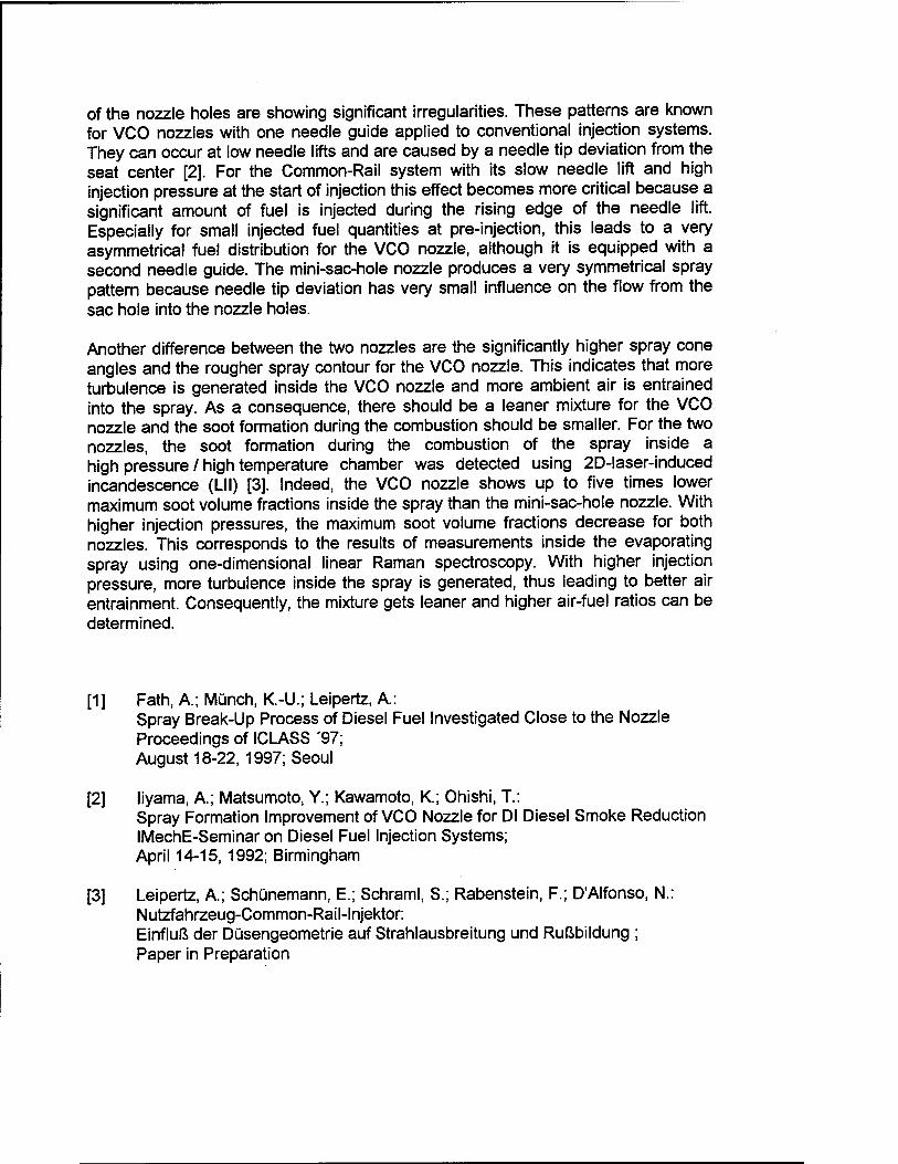
of the nozzle holes are showing significant irregularities. These patterns are known for VCO nozzles with one needle guide applied to conventional injection systems. They can occur at low needle lifts and are caused by a needle tip deviation from the seat center [2]. For the Common-Rail system with its slow needle lift and high injection pressure at the start of injection this effect becomes more critical because a significant amount of fuel is injected during the rising edge of the needle lift. Especially for small injected fuel quantities at pre-injection, this leads to a very asymmetrical fuel distribution for the VCO nozzle, although it is equipped with a second needle guide. The mini-sac-hole nozzle produces a very symmetrical spray pattern because needle tip deviation has very small influence on the flow from the sac hole into the nozzle holes.
Another difference between the two nozzles are the significantly higher spray cone angles and the rougher spray contour for the VCO nozzle. This indicates that more turbulence is generated inside the VCO nozzle and more ambient air is entrained into the spray. As a consequence, there should be a leaner mixture for the VCO nozzle and the soot formation during the combustion should be smaller. For the two nozzles, the soot formation during the combustion of the spray inside a high pressure / high temperature chamber was detected using 2D-laser-induced incandescence (LII) [3]. Indeed, the VCO nozzle shows up to five times lower maximum soot volume fractions inside the spray than the mini-sac-hole nozzle. With higher injection pressures, the maximum soot volume fractions decrease for both nozzles. This corresponds to the results of measurements inside the evaporating spray using one-dimensional linear Raman spectroscopy. With higher injection pressure, more turbulence inside the spray is generated, thus leading to better air entrainment. Consequently, the mixture gets leaner and higher air-fuel ratios can be determined.
[1] Fath, A; Münch, K.-U.; Leipertz, A: Spray Break-Up Process of Diesel Fuel Investigated Close to the Nozzle Proceedings of ICLASS '97; August 18-22, 1997; Seoul
[2] liyama, A.; Matsumoto, Y.; Kawamoto, K.; Ohishi, T.: Spray Formation Improvement of VCO Nozzle for Dl Diesel Smoke Reduction IMechE-Seminar on Diesel Fuel Injection Systems; April 14-15, 1992; Birmingham
[3] Leipertz, A; Schünemann, E.; Schraml, S.; Rabenstein, F.; D'Alfonso, N.: Nutzfahrzeug-Common-Rail-lnjektor: Einfluß der Düsengeometrie auf Strahlausbreitung und Rußbildung ; Paper in Preparation
Visualisations of High-Pressure Sprays and their Combustion Thierry Baritaud and Dean Verhoeven
Institut Frangais du Petrole
Imaging techniques have been combined to form a database of the macroscopic properties of sprays produced by a common- rail injection system in a diesel simulation cell.
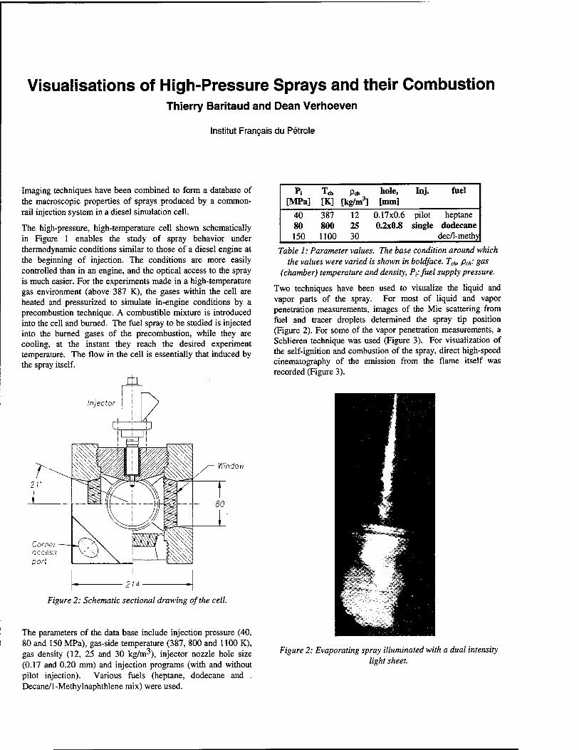
The high-pressure, high-temperature cell shown schematically in Figure 1 enables the study of spray behavior under thermodynamic conditions similar to those of a diesel engine at the beginning of injection. The conditions are more easily controlled than in an engine, and the optical access to the spray is much easier. For the experiments made in a high-temperature gas environment (above 387 K), the gases within the cell are heated and pressurized to simulate in-engine conditions by a precombustion technique. A combustible mixture is introduced into the cell and burned. The fuel spray to be studied is injected into the burned gases of the precombustion, while they are cooling, at the instant they reach the desired experiment temperature. The flow in the cell is essentially that induced by the spray itself.
i±L Injector
Window
Figure 2: Schematic sectional drawing of the cell.
The parameters of the data base include injection pressure (40, 80 and 150 MPa), gas-side temperature (387, 800 and 1100 K), gas density (12, 25 and 30 kg/m^), injector nozzle hole size (0.17 and 0.20 mm) and injection programs (with and without pilot injection). Various fuels (heptane, dodecane and . Decane/1-Methylnaphthlene mix) were used.
Pi Teh Pdl hole, [MPa] [K] [kg/m3] [mm]
Inj. fuel
40 80 150
387 800 1100
12 25 30
0.17x0.6 0.2x0.8
pilot heptane single dodecane dec/1-methy
Table 1: Parameter values. The base condition around which the values were varied is shown in boldface. Tch> pch: gas
(chamber) temperature and density, Pi.-fuel supply pressure.
Two techniques have been used to visualize the liquid and vapor parts of the spray. For most of liquid and vapor penetration measurements, images of the Mie scattering from fuel and tracer droplets determined the spray tip position (Figure 2). For some of the vapor penetration measurements, a Schlieren technique was used (Figure 3). For visualization of the self-ignition and combustion of the spray, direct high-speed cinematography of the emission from the flame itself was recorded (Figure 3).
Figure 2: Evaporating spray illuminated with a dual intensity light sheet.
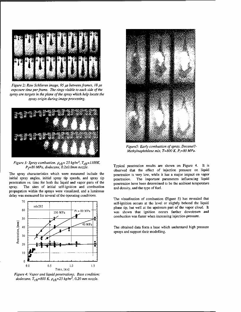
Figure 2: Raw Schlieren image, 95 JJS between frames, 18 /JS
exposure time per frame. The rings visible to each side of the spray are targets in the plane of the spray which help locate the
spray origin during image processing.
Figure 3: Spray combustion. pcn= 25 kg/mJ, Tcn=1100K, Pl=80 MPa, dodecane, 0.2x0.8mm nozzle.
The spray characteristics which were measured include the initial spray angles, initial spray tip speeds, and spray tip penetration vs. time for both the liquid and vapor parts of the spray. The sites of initial self-ignition and combustion propagation within the sprays were visualized, and a luminous delay was measured for several of the operating conditions.
0.5 1.0 Time, [ms]
Figure 4: Vapor and liquid penetrations. Base condition: dodecane, Tcn=800 K, pcn=25 kg/m>, 0.20 mm nozzle.
FigureS': Early combustion of spray. Decane/1- Methylnaphthlene mix, T=800 K, P(=80MPa.
Typical penetration results are shown on Figure 4. It is observed that the effect of injection pressure on liquid penetration is very low, while it has a major impact on vapor penetration. The important parameters influencing liquid penetration have been determined to be the ambient temperature and density, and the type of fuel.
The visualisation of combustion (Figure 5) has revealed that self-ignition occurs at the level or slightly behond the liquid phase tip, but well at the upstream part of the vapor cloud. It was shown that ignition occurs farther dowstream and combustion was faster when increasing injection pressure.
The obtained data form a base which understand high pressure sprays and support their modelling.
Pitfalls and promises of LIF diagnostics in Diesel engines Nico Dam
University of Nijmegen, Applied Physics (Diesel Lab) Toernooiveld 1, NL-6525 ED Nijmegen, The Netherlands
e-mail: [email protected]
One of the research strategies towards clean Diesel engines aims at improving the know- ledge of combustion details by quantitative, non-intrusive measurements of specific mole- cular distributions during the engine cycle. Ideally, such measurements should yield crank angle resolved molecular distributions throughout the whole cylinder volume, but this ideal is still far away, if feasible at all. Two-dimensional distributions of specific molecules can, however, be obtained by means of Laser Induced Fluorescence (LIF) [1].
LIF is probably the only optical diagnostic technique that is sensitive enough to pro- vide crank angle resolved 2D molecular distributions. The translation of measured LIF signals into (semi-)quantitative molecular densities does, however, meet some consider- able obstacles, most of them due to the adverse experimental conditions that are posed by the interior of an internal combustion engine.
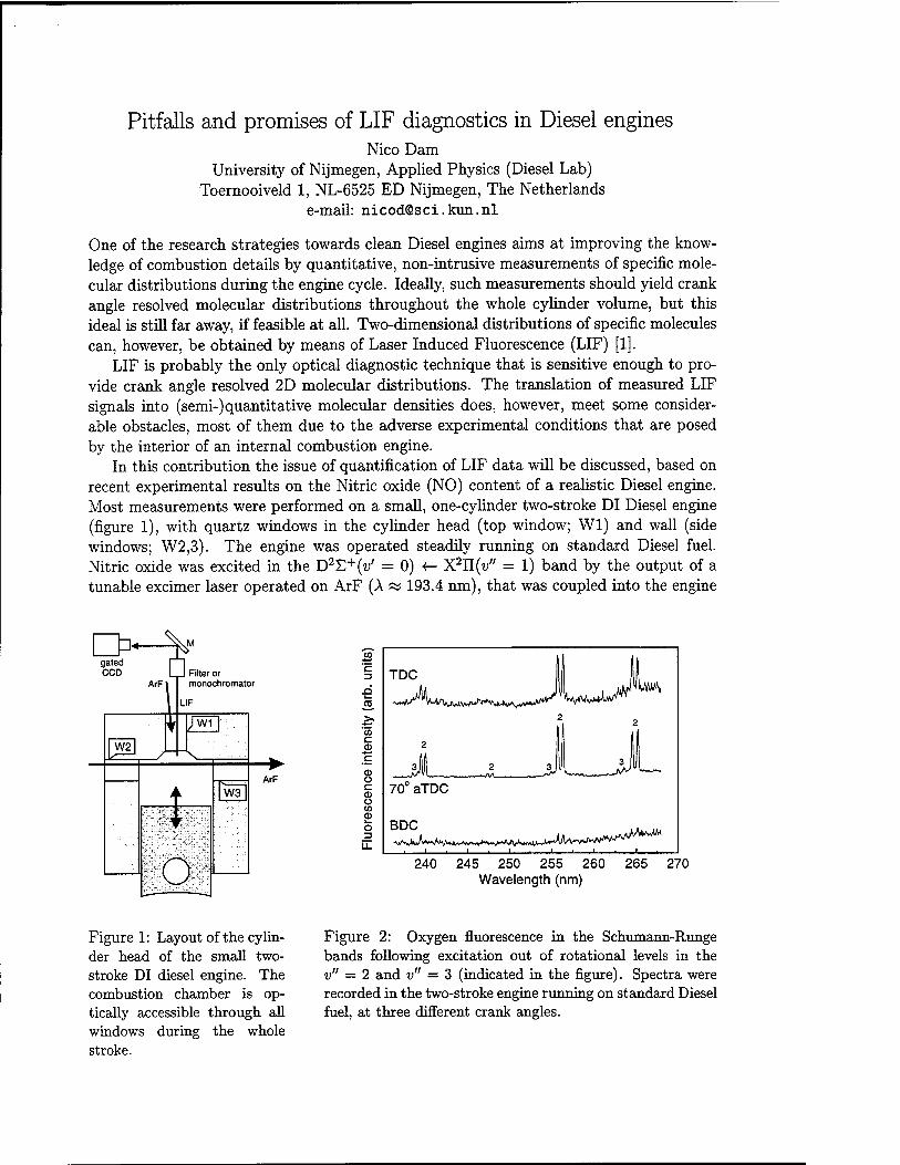
In this contribution the issue of quantification of LIF data will be discussed, based on recent experimental results on the Nitric oxide (NO) content of a realistic Diesel engine. Most measurements were performed on a small, one-cylinder two-stroke DI Diesel engine (figure 1), with quartz windows in the cylinder head (top window; Wl) and wall (side windows; W2,3). The engine was operated steadily running on standard Diesel fuel. Nitric oxide was excited in the D2E+(i/ = 0) <- X2U(v" = 1) band by the output of a tunable excimer laser operated on ArF (A « 193.4 nm), that was coupled into the engine
CO
hi il c 3 TDC | I .a CO ^^/^WA^*^^ VJWA*^ >> ?. 2 CO c
CD J__^_JLJ Ü c CD Ü
70° aTDC
CD
o LL
BDC
1 . 1 . 1 1 . 1 . 1
240 245 250 255 260 265 270 Wavelength (nm)
Figure 1: Layout of the cylin- der head of the small two- stroke DI diesel engine. The combustion chamber is op- tically accessible through all windows during the whole stroke.
Figure 2: Oxygen fluorescence in the Schumann-Runge bands following excitation out of rotational levels in the v" = 2 and v" = 3 (indicated in the figure). Spectra were recorded in the two-stroke engine running on standard Diesel fuel, at three different crank angles.
either through one of the side windows or through the top window. Fluorescence was always detected through the top window, and either dispersed in an Optical Multichannel Analyser (OMA) or imaged by a gated CCD camera through a narrow-band transmission filter.
The relation between the measured fluorescence signal 5LIF and the local NO density pNo can be written as
SLIF = C f /?No(a:)/L(a;)AF(a;)/ViJ(T)p(P,T)5K,i/a)dV (1) Jv
where the integration is taken over the whole laser-illuminated volume seen by the de- tector. C is a proportionality constant including experimental parameters like collection efficiency, window transmission, camera sensitivity, etc., I-L(X) is the local intensity of the laser beam and Ap(x) is a factor describing the attenuation of the laser induced flu- orescence on its way to the top window. The Boltzmann fraction fv,j(T) describes the temperature dependent population of the probed state. The Stern-Vollmer factor p(P, T) accounts for the competition between radiative and non-radiative (collision induced) de- cay of excited molecules, and gfa, z/a) is the overlap integral of the laser line profile with the NO absorption spectrum. With the exception of the apparatus constant C, all fac- tors in eq. 1 depend on pressure and temperature and, therefore, on crank angle. Even worse, they may depend on the position within the combustion chamber. Therefore, any meaningful comparison of fluorescence signals at different moments during the stroke or under different engine operating conditions (fuel, load, ... ) must necessarily consider all of these factors.
Generally speaking, the problem boils down to the determination of local gas temper- ature and local laser intensity. A mean gas temperature can be derived from the crank angle dependent pressure in and volume of the combustion chamber. Alternatively, a temperature may be derived from the spectral distribution of the natural flame emission, largely arising from glowing soot particles. These two temperatures do not agree, the
-20 0 20 40 60 80 100 Crank angle (° aTDC)
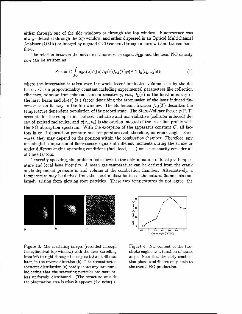
Figure 3: Mie scattering images (recorded through the cylindrical top window) with the laser travelling from left to right through the engine (a) and, 40 nsec later, in the reverse direction (b). The reconstructed scatterer distribution (c) hardly shows any structure, indicating that the scattering particles are more-or- less uniformly distributed. (The structure outside the observation area is what it appears (i.e. noise).)
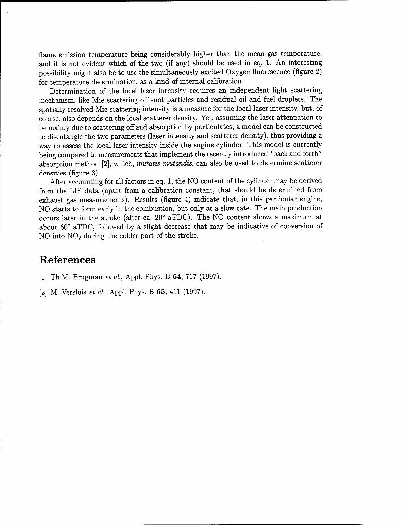
Figure 4: NO content of the two- stroke engine as a function of crank angle. Note that the early combus- tion phase contributes only little to the overall NO production.
flame emission temperature being considerably higher than the mean gas temperature, and it is not evident which of the two (if any) should be used in eq. 1. An interesting possibility might also be to use the simultaneously excited Oxygen fluorescence (figure 2) for temperature determination, as a kind of internal calibration.
Determination of the local laser intensity requires an independent light scattering mechanism, like Mie scattering off soot particles and residual oil and fuel droplets. The spatially resolved Mie scattering intensity is a measure for the local laser intensity, but, of course, also depends on the local scatterer density. Yet, assuming the laser attenuation to be mainly due to scattering off and absorption by particulates, a model can be constructed to disentangle the two parameters (laser intensity and scatterer density), thus providing a way to assess the local laser intensity inside the engine cylinder. This model is currently being compared to measurements that implement the recently introduced "back and forth" absorption method [2], which, mutatis mutandis, can also be used to determine scatterer densities (figure 3).
After accounting for all factors in eq. 1, the NO content of the cylinder may be derived from the LIF data (apart from a calibration constant, that should be determined from exhaust gas measurements). Results (figure 4) indicate that, in this particular engine, NO starts to form early in the combustion, but only at a slow rate. The main production occurs later in the stroke (after ca. 20° aTDC). The NO content shows a maximum at about 60° aTDC, followed by a slight decrease that may be indicative of conversion of NO into NO2 during the colder part of the stroke.
References
[1] Th.M. Brugman et al, Appl. Phys. B 64, 717 (1997).
[2] M. Versluis et al, Appl. Phys. B 65, 411 (1997).
Chemical kinetics and key processes in hydrocarbon containing flames
J. VANDOOREN. Universite Catholique de Louvain. Belgium
The combustion process in compression-ignition engines or diesel engines is strongly dependent on operating conditions which are very different from spark ignition engines. It is an unsteady, heterogeneous combustion process which involves premixed, diffusion and turbulent flame characteristics varying along the compression-expansion cycle. A simple treatment of the combustion ignition and propagation is not realistic and although many efforts are devoted to its understanding it remains lacking quantitative description of such complex phenomena. The liquid fuel injected in the combustion chamber atomizes, vaporizes and mixes with the high temperature high pressure air. Spontaneous ignition occurs after a delay period (few ms) where some portions of fuel and air are mixed. Then the pressure increases, compression of the unburned portion of the charge occurs shortening the ignition delay to finally burn. Injection continues untill the desired amount of fuel has penetrated the combustion chamber while the fuel air mixture burns simultaneously. Diesel engines must operate under lean conditions to avoid the formation of excessive amounts of soot (<|>= 0.5- 0.6). Also for small engines, the combustion process must be ended in due time by appropiate turbulent fuel air mixing within the flammability limits. An important parameter in diesel engines is the ignition delay, which is the time interval between the start of injection and the start of combustion. The chemical component of the ignition delay is the autoignition in premixed fuel air mixtures. It depends on the fuel composition, on the air pressure and temperature (low or high compression ratios), on the injection timing and loading as well as on mixing efficiency. The autoignition ability of a fuel is defined by the cetane number (cetane = n-hexadecane). A very short ignition delay is required to ensure complete and useful combustion and it is obtained when the cetane number is high allowing to produce ignition well before all the fuel is injected.
The correlation of the fuel molecules structure with the cetane number is as follows: Straight chain of alkanes have the lowest ignition delay which improves with the length of the chain. The highest ignition delay is observed for aromatics and alcohols. For isoalkanes, the ignition delay becomes longer with the degree of branching. In the autoignition of alkanes (nC>3), alkenes, large alcohols and aldehydes the occurrence of cool flames is noticed. Normal alkanes are more reactive than their branched isomers and the reactivity increases considerably from C3 to C6. The lowest ignition temperature at a given pressure is observed for rich mixtures (>10% in air).
A good example of the ignition behaviour of n-alkanes is n-heptane. The main ignition delay depends linearly on the reciprocal temperature at low (T<700K) and at high temperature (T>1100K). Inbetween it exists a non linear behaviour with a negative temperature coefficient (NTC). Near the minimum temperature, a two stage ignition is observed. With increasing pressure and as with increasing equivalence ratios the NTC region shifts to higher temperature and lower ignition delays. Three temperature ranges can be examined within specific key branching reactions occur: - Below 900K, reactions of alkyl radicals (R) with molecular oxygen will give chain branching precursors RO2 where R is produced by H-abstraction from the fuel molecule. Above 800K the reverse reaction becomes important and therefore the reaction approaches equilibrium. The R02 radical can isomerize by internal H-atom abstraction to produce a QOOH radical which can decompose into an OH radical and a epoxide (or H02 and alkene) and the efficiency of this process depends on the type of C-H bond to be broken. The QOOH radical can also react with 02 to produce a OOQOOH radical followed by an internal H- atom
abstraction (HOOQ'OOH). Such a molecule can dissociate producing OH radicals and a carbonyl containing compound. Such reactions lead to chain branching and therefore to accelerated ignition. Finally, OH radicals will react rapidly with the fuel and the heat release will increase the temperature and therefore the high temperature regime would be attained. - Between 900K and HOOK, H202 plays a key role by promoting hot autoignition by dissociation into two hydroxyl radicals. The formation of H202 will proceed through reaction of H02 with aldehydes or by recombination of two H02 radicals. H02 radicals and olefins will be produced by the reaction of R with 02. The key reaction in this temperature range is the decomposition reaction of H202
- Above HOOK, the main branching reaction is H + 02 -* OH + O
which means at first sight the independence of the structure of the fuel molecule to ensure propagation of the flame. H atoms are readily formed through propagation reactions like H2 + OH-»H20 + H,H2 + 0->OH + H,CO + OH->C02 + H,etc At the ignition point of view, the decomposition of the R radical to produce H atoms is necessary to start the chain reaction mechanism. Therefore for most of hydrocarbons, two types of reaction are necessary to ensure self propagation of the flame: the above branching reaction together with one or more decomposition reactions. The first reaction, endothermic by about 65 kJ/mol, produces OH radicals and O-atoms which will react with the fuel. The second type of reactions, the dissociation ones, are also essential and are more endothermic. A simple argument corroborates this statement. Indeed, from the overall stoichiometric chemical equation of the oxidation of a fuel CxHyOzNw
CxHyOzNw + (x + y/4 -z/2) 02 -> x C02 + yli H20 + w/2 N2
it is easy to determine the change An of the total number of either particles, or molecules, or moles. An is the difference of the number of moles of products minus that of reactants.
The change of the total number of moles An for non cyclic hydrocarbon fuels can be easily calculated from the expression:
An = (x -1 - p)/2 where p is the number of n bonds present in the molecule. Therefore this simple expression immediately indicates the minimum change of the total number of particles in any hydrocarbon/oxygen burning systems (cycloalkanes and aromatics excluded).
According to this analysis, it comes out that almost all fuels burn with an increase of the total number of moles. It means that decomposition processes must occur in the reaction zone and any combustion mechanism has to include this kind of elementary reactions besides the usual bimolecular and termolecular radical reactions. Furthermore it is also feasible to evaluate the minimum percentage of decomposition per elemental carbon (% dec) of the fuel molecule. It can be calculated from %dec = 100An/ x For instance, in ethane oxygen flames,
C2H5 + 3.5 02 -> 2 C02 + 3 H20 An = 0.5 the decomposition fraction per carbon atom will be at least 25%. Molecules susceptible to dissociate are ethyl radicals
C2H5 -> C2H4 + H AH = + 163 kJ/mol and formyl radicals
CHO -> CO + H AH= + 65 kJ/mol This last reaction occurs in all hydrocarbon flames. For larger hydrocarbons the % dec will increase towards the 50% limit.
Detailed Chemical Modeling of Pollutant Formation in DI-Diesel Engines
H. Barths, N. Peters
Institut für Technische Mechanik, RWTH Aachen
Flamelet modeling allows the application of compre- hensive chemical mechanisms, which include all relevant chemical combustion processes that occur in a DI Diesel engine during autoignition, the burnout in the partially premixed phase, the transition to diffusive burning and formation of pollutants like NOx and soot. Since a de- tailed description of the model is given in previous pub- lications [1,2] only the fundamental concept and the im- plementation into 3-D CFD codes will be outlined here. The basic idea of the model is the numerical separation of fluid dynamics and chemistry. Under the assumption that there exists a thin flame sheet, such that turbulent time and length scales are large compared to the chem- ical ones, the reaction zone can not be be intruded by turbulent eddies. The flame sheet can only be streched by the turbulent movement and the chemical structure of the flame remains, since chemical reactions are fast enough to compensate disturbances. Then, the govern- ing equations for the species mass balance and energy conservation can be transformed to a one-dimensional form and the inner structure of the laminar reaction zone can be determined in a one-dimensional calcula- tion.
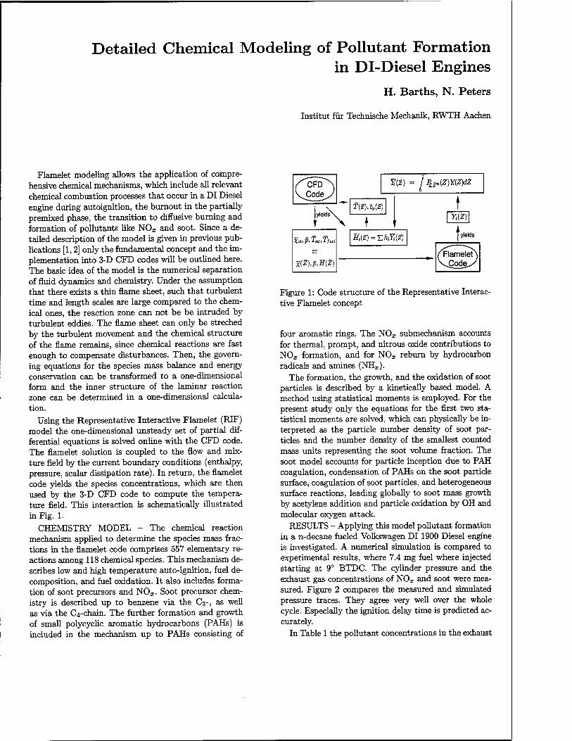
Using the Representative Interactive Flamelet (RIF) model the one-dimensional unsteady set of partial dif- ferential equations is solved online with the CFD code. The flamelet solution is coupled to the flow and mix- ture field by the current boundary conditions (enthalpy, pressure, scalar dissipation rate). In return, the flamelet code yields the species concentrations, which are then used by the 3-D CFD code to compute the tempera- ture field. This interaction is schematically illustrated in Fig. 1.
CHEMISTRY MODEL - The chemical reaction mechanism applied to determine the species mass frac- tions in the flamelet code comprises 557 elementary re- actions among 118 chemical species. This mechanism de- scribes low and high temperature auto-ignition, fuel de- composition, and fuel oxidation. It also includes forma- tion of soot precursors and NOx- Soot precursor chem- istry is described up to benzene via the C3-, as well as via the C^chain. The further formation and growth of small polycyclic aromatic hydrocarbons (PAHs) is included in the mechanism up to PAHs consisting of
JT(5) = I ifrwyfldz
or
x(Z),p,H(Z)
T(x),Cp(S)
' \ ♦ '
Ht(x) = T.hiYi{x)
t Y>(Z)\
I yields
Flamelet JDode^.
Figure 1: Code structure of the Representative Interac- tive Flamelet concept
four aromatic rings. The NOj, submechanism accounts for thermal, prompt, and nitrous oxide contributions to NOJC formation, and for NO^ reburn by hydrocarbon radicals and amines (NHr).
The formation, the growth, and the oxidation of soot particles is described by a kinetically based model. A method using statistical moments is employed. For the present study only the equations for the first two sta- tistical moments are solved, which can physically be in- terpreted as the particle number density of soot par- ticles and the number density of the smallest counted mass units representing the soot volume fraction. The soot model accounts for particle inception due to PAH coagulation, condensation of PAHs on the soot particle surface, coagulation of soot particles, and heterogeneous surface reactions, leading globally to soot mass growth by acetylene addition and particle oxidation by OH and molecular oxygen attack.
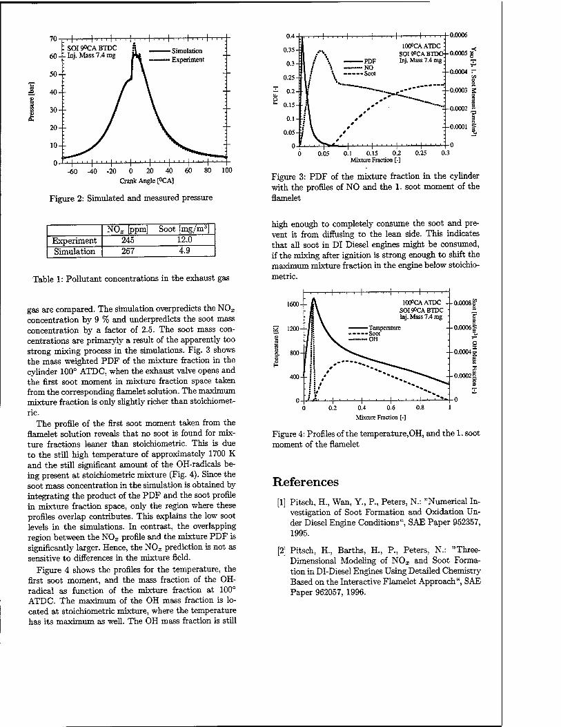
RESULTS - Applying this model pollutant formation in a n-decane fueled Volkswagen DI 1900 Diesel engine is investigated. A numerical simulation is compared to experimental results, where 7.4 mg fuel where injected starting at 9° BTDC. The cylinder pressure and the exhaust gas concentrations of NOx and soot were mea- sured. Figure 2 compares the measured and simulated pressure traces. They agree very well over the whole cycle. Especially the ignition delay time is predicted ac- curately.
In Table 1 the pollutant concentrations in the exhaust
-60 -40 -20 0 20 40 60 80 100
Crank Angle [°CA]
Figure 2: Simulated and measured pressure
I ■ . ■ ■ |. ■ ■ ■.
lOCPCAATDC : S0I9°CABTDG Inj. Mass 7.4 mg:
0.0006
0.0005 g*
0.0004 r
-- 0.0003 S o |
-4-0.0002 3
| •o.oooi I
0.1 0.15 0.2 Mixture Fraction [-]
0.25 0.3
Figure 3: PDF of the mixture fraction in the cylinder with the profiles of NO and the 1. soot moment of the flamelet
NOx [ppm] Soot [mg/ma] Experiment 245 12.0 Simulation 267 4.9
Table 1: Pollutant concentrations in the exhaust gas
gas are compared. The simulation overpredicts the NOz
concentration by 9 % and underpredicts the soot mass concentration by a factor of 2.5. The soot mass con- centrations are primaryly a result of the apparently too strong mixing process in the simulations. Fig. 3 shows the mass weighted PDF of the mixture fraction in the cylinder 100° ATDC, when the exhaust valve opens and the first soot moment in mixture fraction space taken from the corresponding flamelet solution. The maximum mixture fraction is only slightly richer than stoichiomet- ric.
The profile of the first soot moment taken from the flamelet solution reveals that no soot is found for mix- ture fractions leaner than stoichiometric. This is due to the still high temperature of approximately 1700 K and the still significant amount of the OH-radicals be- ing present at stoichiometric mixture (Fig. 4). Since the soot mass concentration in the simulation is obtained by integrating the product of the PDF and the soot profile in mixture fraction space, only the region where these profiles overlap contributes. This explains the low soot levels in the simulations. In contrast, the overlapping region between the NOx profile and the mixture PDF is significantly larger. Hence, the NOx prediction is not as sensitive to differences in the mixture field.
Figure 4 shows the profiles for the temperature, the first soot moment, and the mass fraction of the OH- radical as function of the mixture fraction at 100° ATDC. The maximum of the OH mass fraction is lo- cated at stoichiometric mixture, where the temperature has its maximum as well. The OH mass fraction is still
high enough to completely consume the soot and pre- vent it from diffusing to the lean side. This indicates that all soot in DI Diesel engines might be consumed, if the mixing after ignition is strong enough to shift the maximum mixture fraction in the engine below stoichio- metric.
1600-
1200--
+ 100°CAATDC
SOI9°CABTDC Inj. Mass 7.4 mg
0.0008 g
0.00061=
0.4 0.6
Mixture Fraction [-]
Figure 4: Profiles of the temperature,OH, and the 1. soot moment of the flamelet
References
[1] Pitsch, H., Wan, Y., P., Peters, N.: "Numerical In- vestigation of Soot Formation and Oxidation Un- der Diesel Engine Conditions", SAE Paper 952357, 1995.
[2] Pitsch, H., Barths, H., P., Peters, N.: "Three- Dimensional Modeling of NOx and Soot Forma- tion in DI-Diesel Engines Using Detailed Chemistry Based on the Interactive Flamelet Approach", SAE Paper 962057, 1996.
Diesel Combustion Study by Optical Diagnostics
B.M.Vaglieco Fluid-dynamics and Combustion Division
Istituto Motori, CNR-Napoli, Italy
The science of optics has always played an important role in the measurement and understanding of combustion phenomena, including not only laboratory flames but also practical combustion devices such as the internal combustion engines. In particular, being the Diesel combustion a two-phase, turbulent mixing-controlled process that includes short time scale phenomena such as turbulence production and dissipation, spray breakup and evaporation, and pollutants formation it is appropriate to make investigation by non intrusive diagnostic techniques that have high temporal and spatial resolution.
Laser Doppler Anemometry (LDA), particle image velocimetry (PIY), and phase Doppler analyzer (PDA) have allowed to evaluate and understand the fluid mechanics in the cylinder in terms of mean motion and turbulence characteristics. By these techniques it is possible to analyze as the air, that is inducted and used in the cylinder, contributes both the air/fuel mixing and flame propagation process during combustion.
In order to investigate as the fuel air mixing influences the combustion process, a lot of techniques have been used widely in the past. First of all high speed direct, backlight and Schlieren cinematography were applied to study spray atomization, fuel penetration and evaporation phenomena. Although cycle resolved, these techniques can not provide spatial quantitative information on the air-fuel mixing in the combustion chamber and only statistical data can be obtained, owing to the instability and highly turbulent nature of a Diesel spray.
Recent developments in laser source and detection systems have permitted to set new 2-D laser sheet imaging diagnostics. The spatial distribution of liquid and vapor of fuel was made inside optical accessible Diesel system both by simultaneous use of laser induced Rayleigh and Mie-scattering imaging and EXCIPLEX technique, based on a fluorescence system. This last technique, even if it is able to distinguish simultaneously between spray liquid and vapor phase, needs of a fluorescence dopant and it is limited to oxygen free atmosphere because the doping molecule is severely quenched by oxygen. A different technique, based on the principle of absorption of ultraviolet laser light by fuel vapor and the scattering of visible laser light by fuel, seemed to give good results because it measures simultaneous the concentrations of vapor and liquid in an evaporating Diesel spray. Being an absorption technique its drawback is the integration across the entire width of spray.
Experimental analysis of intermediate steps of ignition and onset of soot formation combustion is generally restricted to measurements of ignition delay
and high speed photography, doping the fuel with copper to create a more luminous emission before the soot formation occurs. These techniques lack of spatial and time resolution and have been overcame partly by imaging the natural chemiluminescence using calibrated intensified video camera. Luminosity imaging and simultaneous planar imaging of laser-induced incandescence and elastic scattering have contributed to detect the onset of soot during the range of time in which a solid particle is formed from fuel molecules
Light extinction, Rayleigh and Mie scattering, laser induced incandescence (LII) and laser induced fluorescence (LIF) have allowed to follow the soot formation and oxidation process in terms of soot particle size and number density, temperature and some species concentration.
The experimental difficulties involved in the following the course of soot formation and oxidation in the environment of the Diesel cylinder are enormous due to the high temperatures, pressures that conditioned extremely the reactive intermediate species occurring.
These diagnostics are applied in optically accessible closed vessel, model combustion chamber, rapid compression machines and optical engine with a moderate swirl in order to reduce the instability and highly turbulent nature of the spray. The advantage of using these devices is to study the influence of a single parameter on the engine internal process and to have large optical accesses for optical measurement techniques. By the way, they do not consider the unsteady environment and role of the swirl motion in the Diesel systems typical of modern IDI and DI engines.
However the high temporal and spatial resolution of optical techniques are a quite useful tool to get a deeper comprehension of the fundamental physics inside Diesel engine, so their improvement is mandatory in the next future.
Diesel Fuel - Balancing Environmental Requirements and Customer Needs
David Britton Shell International Petroleum Company Shell Centre London SEI 7NA
Throughout the world demand for road transport continues to increase. However the local and global impact of emissions from the road transport sector continues generate concern in many countries. The diesel engine remains one of the most efficient and cost effective transport options. Recent advances in vehicle technology and fuel quality have significantly reduced emissions from the levels of 10 years ago. Nevertheless, concern over emissions of nitrogen oxides (NOx) and paniculate matter (PM), particularly in urban areas, continues to produce pressure for even lower emission levels.
As well as the concern over local air quality, there is also increasing concern over the levels of greenhouse gases in The Earth's atmosphere. C02is one of the principal greenhouse gases and levels of C02 emissions are directly related to energy use. Since the diesel engine is more efficient that it's gasoline counterpart, diesel vehicles produce less C02 on a per mile travelled basis. However, when comparing emissions characteristics of fuels it is important that they are considered on a well-to-wheels basis, looking at the energy and emissions generated during their production as well as use. This is particularly important when considering radical modifications to existing fuel specifications, because some of these will significantly increase refinery energy consumption and decrease product yield. These effects mean that emissions of C02 and other pollutants could actually increase when considered on a well-to wheels basis
The European Programme on Emissions, Fuels and Engine technologies (EPEFE) examined the effects of diesel fuel quality on emissions from modern diesel vehicles and concluded that the effect of vehicle technology was significantly greater than that of differences in fuel quality. However, individual fuel parameters can have an effect on emissions and in this paper we will discuss the effects of such changes.
A number of alternatives to conventional diesel fuel have been proposed and indeed are in use in many countries. It is important to understand that, the economic and social imperatives which drive such initiatives will be different in different places and so, solutions will always be location-specific. Alternatives can broadly be considered in two categories : those which serve as replacements for diesel fuel, examples being LPG and CNG, and those which are blended with conventional diesel fuel, examples being synthetic diesel, or biodiesel. Shell has been involved in many projects looking at both categories of alternatives in many different countries. Some trials have shown local success, while other have failed after varying periods of time. However to date it would be reasonable to say that no alternative has yet been found that does not require the customer to make some compromise either in terms of cost, performance or operational flexibility. In this work we will present data from Shell trials of biodiesel, and the gaseous fuels LPG and CNG. We will also describe the patented Shell Middle Distillate Synthesis (SMDS) process by which natural gas is converted into a diesel-like fuel. This product has been tested in diesel engines and has shown excellent emissions performance.
The most well-known environmentally modified diesel fuel available today is "city diesel", an ultra low sulphur, low density product such as the Swedish Class 1 fuel. It is important to understand that the introduction of Swedish Class 1 was supported by large tax incentives. Whilst such fuels offer undoubted emissions benefits, particularly when compared with the quality of fuel available at the time of it's initial introduction, as the quality of the general diesel pool increases, the scale of realizable benefits decreases. Severely reformulated fuels are also not without their problems, the introduction of Swedish Class 1 was associated with a loss in fuel lubricity which led to a number of equipment failures. Although the oil industry has overcome this problem it nevertheless remains an example of how changes to fuels can lead to difficulties for users. Customers in Switzerland have also experienced operational problems
associated with the distribution of diesel fuels with physico-chemical characteristics similar to those of "city diesel". Users of Swedish Class 1 fuels have reported a loss of power and increase in fuel consumption. Therefore, the economic and operational costs to customers associated with the use of reformulated fuels are not inconsiderable and as such their cost effectiveness should be considered very carefully prior to any introduction.
Theoretical calculations, backed by field data, show that at a level of 0.05% sulphur, the contribution of sulphate and associated water to particulate emissions is already very small, therefore further reductions in sulphur level, achieved at a cost of increased refinery energy consumption, show a rapidly diminishing emissions benefit. However as exhaust treatment devices become more common it is recognised that lower sulphur fuels might become necessary to enable these to function efficiently. This clearly illustrates the need for a rational approach to managing urban air quality in which the costs and scale of potential benefits arising from a ranae of measures are assessed in order that the most cost-efficient measures can be utilised.
Shell's most recent experience of the use of biodiesel has been in France. Shell France introduced biodiesel containing 30% Rape oil methyl ester (RME) for fleet customers with central fuelling facilities. The biodiesel blend showed some benefits in terms of emissions of PM over diesel fuel with 0.2% sulphur, however with the introduction of 0.05% sulphur diesel fuel the scale of this benefit was greatly reduced. Fleet operators expressed concern over the validity of vehicle warranties relating to vehicles using the new fuel and, in the end the product was withdrawn although RME is still used as a low percentage blending component. Overall, the economics of biofuels in relation to their environmental benefits remains generally unfavourable. However their relative competitiveness will depend greatly on local circumstances and priorities.
Both CNG and LPG can be considered as viable alternatives to diesel fuel or gasoline, although both require favourable tax treatment to compete with conventional fuels. There is wide international experience with both of these fuels as alternatives to diesel. LPG remains the most widely used alternative fuel in use today with almost 4 million vehicles using it on a world-wide basis. The use of either of the gaseous fuels in vehicles which would normally use diesel fuel requires significant engine modifications. However such initiatives can help to improve urban air quality since both result in very low particulate emissions. For the operator there are penalties in terms of vehicle range and CNG has the further difficulty of requiring longer refuelling times which can interfere with operating schedules. Nevertheless a case can be made to support the use of LPG as an alternative fuel for short-range, local transport where improvements in local air quality can be significant.
In summary, Shell's global experience suggests that, the most efficient means of urban transport, both in terms of environmental performance and economics, remains the combination of modern conventional diesel fuel and modern engines, particularly where the latter utilise modern emission control technology. In certain environments the use of alternative or severely reformulated fuels might be indicated, however our experience has shown that most, if not all of these will require some element of compromise from the user. This is a very important point because in the end it will be the customer who decides what will be used. Customers differ in different parts of the world and so it is inevitable that there will be differences in solutions adopted in different countries. However our experience would suggest that, for an alternative to be truly viable in the longer term it must be based on sound, viable economics.
Environmental aspects of fine particles and soot Andrea Fischer-Riedmann Swiss Federal Laboratories for Materials Testing and Research (EMPA) 8600 Dübendorf, Switzerland
Concern for our environment is not a new phenomenon. Humans have been exposed to smoke, the archetypical air pollutant, since the earliest use of fire. Smoke problems existed even in great cities of antiquity. It was 13th century London where air pollution became particularly evident. Later, when coal was used as a fuel the problem became even more severe. The problems of a coal burning city were fully developed in London of the 17th century, with effects on buildings, health, plants, visibility, etc., all well described by John Evelyn in 1661 (Singh 1995).
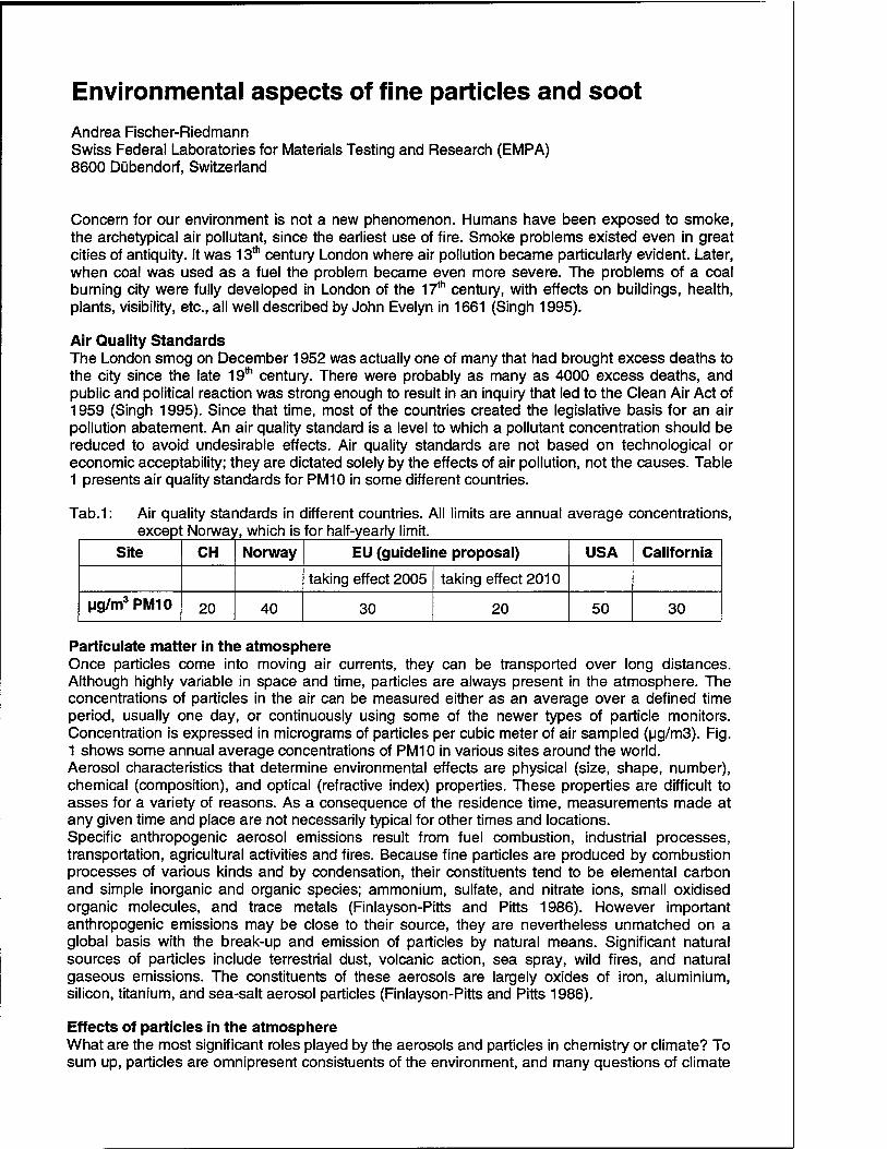
Air Quality Standards The London smog on December 1952 was actually one of many that had brought excess deaths to the city since the late 19th century. There were probably as many as 4000 excess deaths, and public and political reaction was strong enough to result in an inquiry that led to the Clean Air Act of 1959 (Singh 1995). Since that time, most of the countries created the legislative basis for an air pollution abatement. An air quality standard is a level to which a pollutant concentration should be reduced to avoid undesirable effects. Air quality standards are not based on technological or economic acceptability; they are dictated solely by the effects of air pollution, not the causes. Table 1 presents air quality standards for PM10 in some different countries.
Tab.1: Air quality standards in different countries. All limits are annual average concentrations, excepl Norway i, which is for half-yearly limit.
Site CH Norway EU (guideline proposal) USA California
taking effect 2005 taking effect 2010
ug/m3PM10 20 40 30 20 50 30
Particulate matter in the atmosphere Once particles come into moving air currents, they can be transported over long distances. Although highly variable in space and time, particles are always present in the atmosphere. The concentrations of particles in the air can be measured either as an average over a defined time period, usually one day, or continuously using some of the newer types of particle monitors. Concentration is expressed in micrograms of particles per cubic meter of air sampled (ug/m3). Fig. 1 shows some annual average concentrations of PM10 in various sites around the world. Aerosol characteristics that determine environmental effects are physical (size, shape, number), chemical (composition), and optical (refractive index) properties. These properties are difficult to asses for a variety of reasons. As a consequence of the residence time, measurements made at any given time and place are not necessarily typical for other times and locations. Specific anthropogenic aerosol emissions result from fuel combustion, industrial processes, transportation, agricultural activities and fires. Because fine particles are produced by combustion processes of various kinds and by condensation, their constituents tend to be elemental carbon and simple inorganic and organic species; ammonium, sulfate, and nitrate ions, small oxidised organic molecules, and trace metals (Finlayson-Pitts and Pitts 1986). However important anthropogenic emissions may be close to their source, they are nevertheless unmatched on a global basis with the break-up and emission of particles by natural means. Significant natural sources of particles include terrestrial dust, volcanic action, sea spray, wild fires, and natural gaseous emissions. The constituents of these aerosols are largely oxides of iron, aluminium, silicon, titanium, and sea-salt aerosol particles (Finlayson-Pitts and Pitts 1986).
Effects of particles in the atmosphere What are the most significant roles played by the aerosols and particles in chemistry or climate? To sum up, particles are omnipresent consistuents of the environment, and many questions of climate
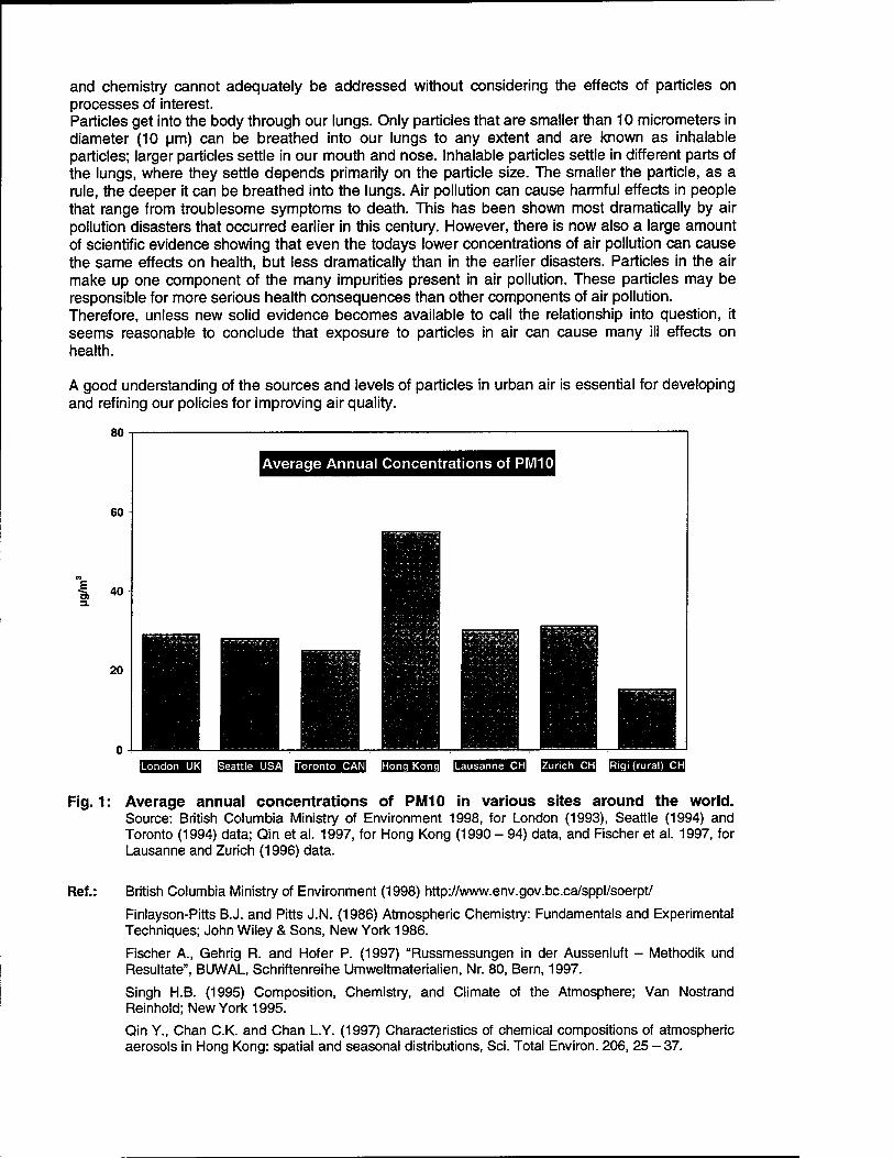
and chemistry cannot adequately be addressed without considering the effects of particles on processes of interest. Particles get into the body through our lungs. Only particles that are smaller than 10 micrometers in diameter (10 urn) can be breathed into our lungs to any extent and are known as inhalable particles; larger particles settle in our mouth and nose. Inhalable particles settle in different parts of the lungs, where they settle depends primarily on the particle size. The smaller the particle, as a rule, the deeper it can be breathed into the lungs. Air pollution can cause harmful effects in people that range from troublesome symptoms to death. This has been shown most dramatically by air pollution disasters that occurred earlier in this century. However, there is now also a large amount of scientific evidence showing that even the todays lower concentrations of air pollution can cause the same effects on health, but less dramatically than in the earlier disasters. Particles in the air make up one component of the many impurities present in air pollution. These particles may be responsible for more serious health consequences than other components of air pollution. Therefore, unless new solid evidence becomes available to call the relationship into question, it seems reasonable to conclude that exposure to particles in air can cause many ill effects on health.
A good understanding of the sources and levels of particles in urban air is essential for developing and refining our policies for improving air quality.
Fig. 1: Average annual concentrations of PM10 in various sites around the world. Source: British Columbia Ministry of Environment 1998, for London (1993), Seattle (1994) and Toronto (1994) data; Qin et al. 1997, for Hong Kong (1990 - 94) data, and Fischer et al. 1997, for Lausanne and Zurich (1996) data.
Ref.: British Columbia Ministry of Environment (1998) http://www.env.gov.bc.ca/sppl/soerpt/ Finlayson-Pitts B.J. and Pitts J.N. (1986) Atmospheric Chemistry: Fundamentals and Experimental Techniques; John Wiley & Sons, New York 1986. Fischer A., Gehrig R. and Hofer P. (1997) "Russmessungen in der Aussenluft - Methodik und Resultate", BUWAL, Schriftenreihe Umweltmaterialien, Nr. 80, Bern, 1997. Singh H.B. (1995) Composition, Chemistry, and Climate of the Atmosphere; Van Nostrand Reinhold; New York 1995. Qin Y., Chan C.K. and Chan L.Y. (1997) Characteristics of chemical compositions of atmospheric aerosols in Hong Kong: spatial and seasonal distributions, Sei. Total Environ. 206, 25-37.
Diesel Particulate Filter: the most promising technology for achieving a significant abatement of Diesel particulate emissions in mass and number
Jacques LEMAIRE, William MUSTEL Rhodia - Automotive Emissions Control - Courbevoie FRANCE
During the past decades, Diesel engine has significantly increased its penetration of the European, and in particular the French, passenger car market. Besides tax advantages, this trend can be explained by different factors among which low fuel consumption is of major importance. However, with the growing concern about urban air quality, Diesel exhaust emissions have become of major importance.
Special attention is now focused on the two major pollutants emitted by diesel engines, i.e: NOx and more recently, particulates. Originally perceived as dirty but inert powder, these particulates are thought to pose a real health risk and recent medical studies identify the smallest ones, generally called ultra-fine particulates, as a major health risk. These particulates have a very large surface area which medical experts suspect as being an aggravating risk factor when the particulates penetrate deep into the lungs (alveoli) and remain deposited there.
Consequently, it became a necessity to improve the characterization of particulates emitted by diesel engines in order to better evaluate the different after-treatments technologies, as well as the effect of engine combustion design or fuel characteristics.
One aim of this paper is to provide a comprehensive summary of major results obtained on particulate size determination in the framework of three European studies performed under the control and sponsorship of British, French and Swiss Environmental Agencies (DETR, ADEME & BUWAL). All the three studies (ETSU, IFP, VERT) find the SMPS (Scanning Mobility Particulate Sizer) as a reliable tool to measure with high accuracy and reproducibility the number of ultra fine particles (smaller than 500 nm) in diesel exhaust at steady state or during transient driving cycles. Special attention was paid on the discrimination of dry soot (carbon) from aerosols that result from exhaust gaseous condensation. This is particularly true when SMPS is applied to particulate size determination at the outlet of Diesel Particulate Filter (DPF) systems: in this case, it was shown that the exhaust has to be treated in order to eliminate condensation of volatile species resulting from a quenching effect downstream of a« hot»trap.
By application of SMPS, it should be noted that size distribution appears to be neither strongly affected by engine characteristics, nor by the engine operating point (engine load/speed). In most cases, a particulate concentration peak centered at about 100 nm in size was detected.
The major conclusion of these studies was that DPF is the only technology capable of significantly reducing the number of particulate emissions. Futhermore, engine and catalyst technologies are not effective in reducing particulate numbers and could even be detrimental (fuel effect was demonstrated to be neutral). Several DPF types were tested within these three studies including surface type filters and deep bed filters. In most cases, trap efficiency as expressed by the reduction ratio in the number of particulates whose diameters are below 500 nm, was found to be 99% and up to 99,9% when some fuel-borne catalysts are used. These studies have also demonstrated that trap efficiency is not affected by engine operating
conditions nor by trap loading.
The main difficulty in DPF technology is trap regeneration. This is because Diesel exhaust temperature levels (120 to 500°C) encountered during normal vehicle operation are significantly lower compared to the temperature required to burn the collected carbon soot (550°C). Uncontrolled soot accumulation in DPF's can result in significant deterioration of engine performance (loss in power, increased fuel consumption), and can also lead to the rapid degradation of the trap material itself during uncontrolled trap regeneration.
There is consequently, a major interest in developing measures that can facilitate or force trap regeneration when necessary. Different measures based on thermal regeneration, i.e based on the increase of the trap inlet temperature (fuel burners, electrical heaters) have been developed in the past. These «active» measures have seen a very limited sucess because of their high complexity, consequent high cost and lack in reliability. At present, none of these measures taken individually seem to be able to offer the
definitive solution.
A parallel approach to thermal regeneration is catalytic « passive » regeneration, where the soot ignition temperature is catalytically reduced to a level that becomes more compatible with normal Diesel exhaust temperature: This catalytic effect can be obtained through a gaseous compound, eg, using N02 as the oxidizing agent, or by fuel-borne additives. Recently, two fuel-borne additives (Ce-based and Iron-based) have been approved by the UBA because of their good toxicological profile and their very positive impact on small particulate abatement when used with DPF. These products do not need the use of low sulphur fuel and can be delivered by on-board dosing systems. In the case of the Ce-based EOLYS fuel additive, trap regeneration temperature as low as 250°C can be observed
Future DPF systems will probably combine the different measures cited above in order to enable reliable regeneration for all vehicle operating conditions, as well as for all engine types. This can be achieved if DPF technology is integrated in a global emissions control strategy using engine or exhaust measures that can provide, in conjunction with a catalyst, the required complement for obtaining the necessary fully safe
emission control systems.

Contributed Papers
Posters
NUMERICAL AND EXPERIMENTAL STUDIES OF HIGH-PRESSURE DIESEL FUEL INJECTION
M. Islam, E. Blümcke AUDI AG, INGOLSTADT, GERMANY
A.D. Gosman IMPERIAL COLLEGE OF SCIENCE, TECHNOLOGY AND MEDICINE, LONDON, UK
ABSTRACT
Computational fluid dynamics (CFD) is gaining importance as a tool for engine de- velopment in the automotive industry. Currently, numerical simulations are routinely used for analysing charge motion in the cylinder during the induction and compression strokes. Several examples of applications of cold-flow simulations are presented.
Progress in the modelling of fuel sprays for Diesel engines is beginning to permit limited numerical investigations of Diesel fuel spray phenomena as well. New fuel injec- tion systems for passenger-car Diesel engines are being developed for which injection pressures are significantly higher than for conventional systems and for which current modelling techniques are expected to provide unsatisfactory results.
The present paper presents an assessment of the ability of current industrial CFD techniques to model such high-pressure fuel sprays. A set of experimental data, ob- tained by a collaborative effort with researchers at the RWTH Aachen, is presented. Laser-induced exciplex fluorescence is used to determine spray angles and penetration, and phase-Doppler anemometry provides information about droplet size and evapo- ration rates for sprays produced by a common-rail fuel-injection system. These ex- perimental data are then compared to simulation results obtained from a commercial CFD code to demonstrate the need for improved spray modelling for high-pressure fuel injection.
Chemical Kinetic Simulations of NOx Reduction in Combustion of Heavy Fuel Oil with Diesel Exhaust Gas -A Case Study using the Flow Tube Approach
Norström,T.*, Kilpinen,R*, Hupa, M.*, Boij, J.**, Broussin,F.***,Weber, R.*** *Äbo Akademi University
**Wärtsilä NSD Finland Oy *** International Flame Research Foundation
Reduction of diesel exhaust gas NOx emission in a pilot-scale furnace, fired with heavy fuel, is
simulated using a special modeling technique. This technique combines three-dimensional flow
calculations and detailed kinetic calculations with a comprehensive elementary reaction scheme. The
simulations are compared with in-furnace and exit gas measurements from the test facility. The
objective has been to give guidance of the parameter values to be tested, to compare simulations
with measured data, and to help in interpretation of the data.
The modeling technique used consists of three steps. First the flow pattern and the concentrations of
the main species (CO, C02, 02, N2, H2, H20, and CJE^OJ in the furnace are calculated using a
commercial CFD code, FLUENT. Then trajectories, representative for the flow, are calculated.
Each trajectory contains information (temperature and concentrations of the main species) from the
flow field. The trajectories are considered as hypothetical "flow tubes". Finally, the "flow tubes"
are transformed into a number of sequential plug flow reactors. In these plug flow reactors (PFR) a
comprehensive elementary reaction mechanism, consisting of 340 reversible reactions between 55
species, is used for simulation of the nitrogen chemistry. The nitrogen species amounts from each
plug flow reactor are taken with to the next. The main species concentration and the temperature
are updated according to the information obtained from the trajectories. The final NOx emission
prediction was based on the NOx concentration in the last PFR, weighed by the relative importance
of the flow tube of the total flow.
The results show that, large reductions of NOx in diesel exhaust gases can be achieved by the
supplementary firing technique. The simulations and the measurements give good qualitative
agreement. The simulations show that the modeling technique can by useful for estimating the
performance and to give guidance for optimization of a required reactor.
ind 2 Conference „ Towards Clean Diesel Engines ", May 14/15, Wiirenlingen
IMPROVED MODELLING FOR KEY SUBPROCESSES IN DIESEL ENGINE COMBUSTION SIMULATIONS
G. Weisser, F.X. Tanner, T. Gradinger, K. Boulouchos
I.C. Engines and Combustion Laboratory Swiss Federal Institute of Technology, ETH
CH-8092 Zürich, Switzerland
(boulouchos(cdlw. iet. mavt. ethz. ch)
Computational Reactive Fluid Dynamics (CRFD) are recognized as a promising tool in Research and Development towards a New Generation of environmental-friendly diesel engines. Application of commercial codes in industrial R&D during the last years has however shown rather limited success and helped identify shortcomings of existing models, which become crucial when quantitative predictions of engine combustion are of importance.
Our work in this context focuses on the development and investigation of improved models for key subprocess, which we believe have a significant impact on the quality of the computational results. We try thereby to continuously confront new theoretical models with non-intrusive experiments carried out in parallel on either constant volume combustion cells or single-cylinder engines. Up to now the break-up and atomization process, the transcritical evaporation of multicomponent fuels, the ignition delay and the early phase of the heat release have been looked at in more detail. Some of them are of relevance not only to diesel engines but also to gas turbines operated with liquid fuels. Our main field of application, based on the substrate of the KIVA-IH Code, are nevertheless large, supercharged, medium and low-speed diesel engines where experience with computational tools for combustion simulations is limited so far.
The experience we have acquired meanwhile suggests that the implemented new modes help to significantly improve the CRFD predictions with regard to spray penetration, evaporation rate, fuel and temperature distribution in the combustion chamber etc. Further work is however necessary for global predictions improvement and there is a long way to go until simulation results become truly predictive for engine-out emissions of pollutants like NOx and soot as well. A step-by-step development procedure and systematic submodel validation are key issues to this end.
J
T Conference „ Towards Clean Diesel Engines ", May 14/15, Wiirenlingen
COMBUSTION AND POLLUTANT FORMATION IN DI DIESEL ENGINES EQUIPPED WITH COMMON-RAIL FUEL INJECTION SYSTEMS
K. Boulouchos, L. Jäger, R. Schubiger, H. Stebler, M.K. Eberle
I.C. Engines and Combustion Laboratory Swiss Federal Institute of Technology, ETH
CH-8092 Zürich, Switzerland
fboulouchos(a),lw. iet. mavt. ethz. ch)
Common-Rail Fuel Injection Systems are promising components towards an improved mixture formation and combustion process in DI diesel engines. Well recognized in the engine community is particularly their unique flexibility for tailoring the injection parameters to the instantaneous combustion requirements over the entire engine operating map.
Beyond that, the focus of interest in our present work is to investigate the combustion behavior of diesel engines equipped with state of the art common-rail injection, in order to detect and interpret particular characteristics, if any, of relevance not only to the thermodynamic efficiency, but also to pollutant formation.
For this purpose three DI diesel engines of distinct size have been extensively investigated in order to provide a consistent data base for answering the questions posed above. The first is a passenger car engine, the second one of a type widely used in heavy duty trucks and the third is a longer medium-speed engine for marine or power generation applications. Heat release analysis together with all other conventional techniques have been involved for the characterization of the combustion performance.
Results obtained so far indicate that for the same thermodynamic efficiency the NOx and soot emissions trade-off is clearly improved with common-rail fuel injection. Moreover increased flexibility is available to reduce engine noise, while thermal and mechanical loading of the engine are similar or even reduced compared to the conventional injection systems. The combination with a Variable Geometry Turbocharger helps in addition to further optimize the mentioned trade off s.
Heat release analysis provides clear insights into the reasons for this behavior. Suitably designed common-rail injectors together with an optimized air path (pressure, temperature, EGR) produce a very small premixed combustion part, high intensity energy conversion in the middle of the combustion duration and a sharp decay in heat release towards the end of it. Extension of these promising results to other engine configurations and enhancing the current interpretation with further computational and optical techniques is in progress.
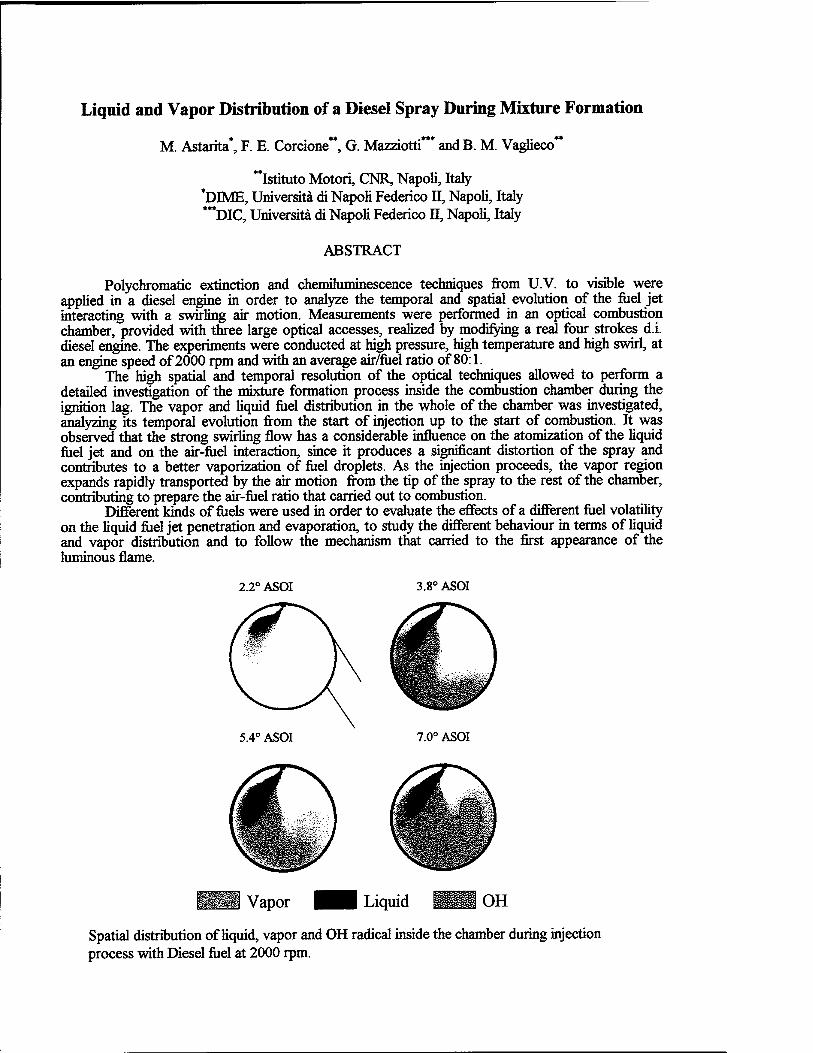
Liquid and Vapor Distribution of a Diesel Spray During Mixture Formation
M. Astarita*, F. E. Corcione**, G. Mazziotti*** and B. M. Vaglieco"
"istituto Motori, CNR, Napoli, Italy *DIME, Universita di Napoli Federico Ü, Napoli, Italy ***DIC, Universita di Napoli Federico n, Napoli, Italy
ABSTRACT
Polychromatic extinction and chemüuminescence techniques from U.V. to visible were applied in a diesel engine in order to analyze the temporal and spatial evolution of the fuel jet interacting with a swirling air motion. Measurements were performed in an optical combustion chamber, provided with three large optical accesses, realized by modifying a real four strokes d.i. diesel engine. The experiments were conducted at high pressure, high temperature and high swirl, at an engine speed of 2000 rpm and with an average air/fuel ratio of 80:1.
The high spatial and temporal resolution of the optical techniques allowed to perform a detailed investigation of the mixture formation process inside the combustion chamber during the ignition lag. The vapor and liquid fuel distribution in the whole of the chamber was investigated, analyzing its temporal evolution from the start of injection up to the start of combustion. It was observed that the strong swirling flow has a considerable influence on the atomization of the liquid fuel jet and on the air-fuel interaction, since it produces a significant distortion of the spray and contributes to a better vaporization of fuel droplets. As the injection proceeds, the vapor region expands rapidly transported by the air motion from the tip of the spray to the rest of the chamber, contributing to prepare the air-fuel ratio that carried out to combustion.
Different kinds of fuels were used in order to evaluate the effects of a different fuel volatility on the liquid fuel jet penetration and evaporation, to study the different behaviour in terms of liquid and vapor distribution and to follow the mechanism that carried to the first appearance of the luminous flame.
2.2° ASOI 3.8°ASOI
5.4° ASOI 7.0° ASOI
^^S Vapor Liquid
Spatial distribution of liquid, vapor and OH radical inside the chamber during injection process with Diesel fuel at 2000 rpm.
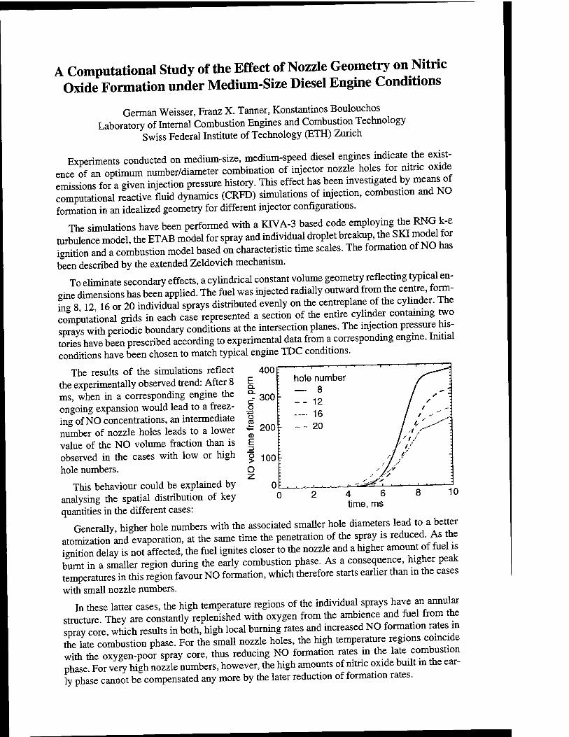
A Computational Study of the Effect of Nozzle Geometry on Nitric Oxide Formation under Medium-Size Diesel Engine Conditions
German Weisser, Franz X. Tanner, Konstantinos Boulouchos Laboratory of Internal Combustion Engines and Combustion Technology
Swiss Federal Institute of Technology (ETH) Zunch
Experiments conducted on medium-size, medium-speed diesel engines indicate the exist- ence of an optimum number/diameter combination of injector nozzle holes for nitric oxide emissions for a given injection pressure history. This effect has been investigated by means of computational reactive fluid dynamics (CRFD) simulations of injection, combustion and NO formation in an idealized geometry for different injector configurations.
The simulations have been performed with a KTVA-3 based code employing the RNG k-e turbulence model, the ETAB model for spray and individual droplet breakup, the SKI model tor ignition and a combustion model based on characteristic time scales. The formation of NO has been described by the extended Zeldovich mechanism.
To eliminate secondary effects, a cylindrical constant volume geometry reflecting typical en- gine dimensions has been applied. The fuel was injected radially outward from the centre, form- ing 8 12 16 or 20 individual sprays distributed evenly on the centreplane of the cylinder. 1 he computational grids in each case represented a section of the entire cylinder containing two sprays with periodic boundary conditions at the intersection planes. The injection pressure his- tories have been prescribed according to experimental data from a corresponding engine. Initial conditions have been chosen to match typical engine TDC conditions.
The results of the simulations reflect the experimentally observed trend: After 8 ms, when in a corresponding engine the ongoing expansion would lead to a freez- ing of NO concentrations, an intermediate number of nozzle holes leads to a lower value of the NO volume fraction than is observed in the cases with low or high hole numbers.
This behaviour could be explained by analysing the spatial distribution of key quantities in the different cases:
Generally, higher hole numbers with the associated smaller hole diameters lead to a better atomization and evaporation, at the same time the penetration of the spray is reduced. As he ignition delay is not affected, the fuel ignites closer to the nozzle and a higher amount of fuel is burnt in a smaller region during the early combustion phase. As a consequence, higher peak temperatures in this region favour NO formation, which therefore starts earlier than in the cases with small nozzle numbers.
In these latter cases, the high temperature regions of the individual sprays have an annular structure They are constantly replenished with oxygen from the ambience and fuel from the spray core, which results in both, high local burning rates and increased NO formation rates m the late combustion phase. For the small nozzle holes, the high temperature regions coincide with the oxygen-poor spray core, thus reducing NO formation rates in the late combustion phase For very high nozzle numbers, however, the high amounts of nitric oxide built in the ear- ly phase cannot be compensated any more by the later reduction of formation rates.
400 E
—,—,—.— 1
hole number Q. — 8 c- 300 o o CO 4= 200
: __ 12 : 16 L _ - 20
£
g 100 :
4 6 time, ms
8 10
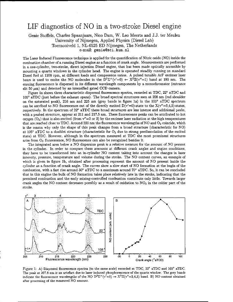
LIF diagnostics of NO in a two-stroke Diesel engine Genie Stoffels, Charles Spaanjaars, Nico Dam, W. Leo Meerts and J.J. ter Meulen
University of Nijmegen, Applied Physics (Diesel Lab) Toernooiveld 1, NL-6525 ED Nijmegen, The Netherlands
e-mail: [email protected]
The Laser Induced Fluorescence technique is applied for the quantification of Nitric oxide (NO) inside the combustion chamber of a running Diesel engine as a function of crank angle. Measurements are performed in a one-cylinder, two-stroke, direct injection Diesel engine, that has been made optically accessible by mounting a quartz windows in the cylinder head. The engine is operated steadily running on standard Diesel fuel at 1200 rpm, at different loads and compression ratios. A pulsed tunable ArF excimer laser beam is used to excite the NO molecules in the D2E+(v'=0) +- X2II(v"=l) band at 193 nm. The ensuing fluorescence is dispersed in its different wavelength components by a monochromator (entrance slit 50 /urn) and detected by an intensified gated CCD camera.
Figure la shows three characteristic dispersed fluorescence spectra, recorded at TDC, 22° aTDC and 105° aTDC (just before the exhaust opens). The broad spectral structures seen at 208 nm (red shoulder on the saturated peak), 216 nm and 225 nm (grey bands in figure la) in the 105° aTDC spectrum can be ascribed to NO fluorescence out of the directly excited D(v'=0)-state to the X(v"=3,4,5)-states, respectively. In the spectrum of 22° aTDC these broad structures are less intense and additional peaks, with a peaked structure, appear at 211 and 217.5 nm. These fluorescence peaks can be attributed to hot oxygen (O2) that is also excited (from v"=2 or 3) by the excimer laser radiation at the high temperatures that are reached close to TDC. Around 225 nm the fluorescence wavelengths of NO and O2 coincide, which is the reason why only the shape of this peak changes from a broad structure (characteristic for NO) at 105° aTDC to a doublet structure (characteristic for O2 due to strong predissociation of the excited state) at TDC. However, although in the spectrum measured at TDC the most prominent structures arise from O2 fluorescence, NO fluorescence can also be recognized besides it.
The integrated area below a NO dispersion peak is a relative measure for the amount of NO present in the cylinder. In order to compare these amounts at different crank angles and engine conditions, they have to be transformed into an in-cylinder NO content taking into account the changes in laser intensity, pressure, temperature and volume during the stroke. The NO content curves, an example of which is given in figure lb, obtained after processing represent the amount of NO present inside the cylinder as a function of crank angle. The curves show a slow start of NO formation at the begin of the combustion, with a fast rise around 30° aTDC to a maximum around 70° aTDC. So, it can be concluded that in this engine the bulk of NO formation takes place relatively late in the stroke, indicating that the premixed combustion and the early mixing-controlled combustion contribute only little. Towards larger crank angles the NO content decreases possibly as a result of oxidation to NO2 in the colder part of the stroke.
V" 3 4 5
A
J \f^ *J\~ j\ TDC
, 22°
x0.4 /
■*—^——1 -, 1"""'1""—■ 1- 1 !*!'i,|ii:
105°
205 210 215 220 225 Fluorescence wavelength (nm)
230 Crank angle (°aTCD)
Figure 1: A) Dispersed fluorescence spectra (to the same scale) recorded at TDC, 22° aTDC and 105° aTDC. The peak at 207.8 nm is an artefact due to laser induced phosphorescence of the quartz window. The grey bands indicate the fluorescence wavelengths of the NO D2E+(v'=0) -*■ X2IT(v"=3,4,5) band. B) NO content obtained after processing of the measured NO amount.
Laser diagnostics in a 6-cylinder 11.6 liter DAF Diesel engine E.J. van den Boom, G.G.M. Stoffels, C.M.I. Spaanjaars, N. Dam,
W.L. Meerts and J.J. ter Meulen University of Nijmegen, Applied Physics (Diesel Lab)
Toernooiveld 1, NL-6525 ED Nijmegen, The Netherlands e-mail: [email protected]
Diesel engines are the most used engines in the transport sector. Because Diesel engines pollute our environment, it is important to get insight in the combustion process and the production of NO and soot. Direct information about the NO production in the combustion process can be obtained by laser diagnostics inside the combustion chamber. Thus far, Laser Induced Flu- orescence (LIF) measurements have been performed in our laboratory in single cylinder 4- and 2-stroke Diesel engines [1, 2]. Recently, experiments have started in a 6-cylinder DAF Diesel engine. One of the six cylinders has been elongated, and the combustion chamber has been made optically accessible by five quartz windows, three at the sides, one in the top and one in the piston crown. This engine modification has been performed in collaboration with DAF, NedCar and the Technical University of Eindhoven (NL). This 6-cylinder engine is motored by 3 cylinders which are working under normal conditions. The elongated, transparant cylinder is not lubricated, in order to minimize the production of soot. Therefore, this cylinder works in skip-fired operation.
An ArF excimer or a dye laser beam excites the NO molecules to the D2S+ or A2E+ state, whereafter the molecules decay back to lower energy levels, which is associated by radiation at different wavelengths, which can be detected by an intensified CCD camera. Additionally, a monochromator can be used to disperse the fluorescence. In this way 2D distributions of the NO molecules can be obtained. In the DAF engine NO has been measured at different crank angles during the combustion cycle by coupling in the laser beam through a side window and detecting the radiation from the NO molecules through the top window by the monochromator/CCD camera combination. Till now we have been able to see NO from 90° aTDC onwards, and we are working on improvements of laser power and engine windows to extend this range to smaller crank angles.
In addition, LIF measurements of NO in a high pressure, high temperature cell are per- formed in the presence of different gases. By the application of LIF detection, information is obtained about quenching and electronic (EET) and vibrational (VET) energy transfer, which is, respectively, the radiationless decay to the ground state, or to another electronically or vi- brationally excited state, as a result of collisions with other particles. The "overall quenching" (i.e. quenching including EET) of NO in the D-state has been studied as a function of pressure in an environment of Ar and N2 at approximately 1000 K. An estimate of the overall quenching cross sections of the NO D-state for these two gases has been made. The quenching cross section for NO in N2 is approximately a factor of 25 larger than the one of NO in Ar. It also appears that the presence of N2 results in a faster energy transfer to the A-state than that of Ar. The interference of the NO spectrum with the O2 spectrum has been studied in excitation and in dispersion. The results of this study have already been applied to the NO measurements in the 2-stroke engine (see poster of G. Stoffels). A new cell is under construction, in order to do more precise measurements.
References
[1] Th.M. Brugman et al, Appl. Phys. B 64, 717 (1997).
[2] G.G.M. Stoffels et al., in K.K. Kuo (ed.), Challenges in Propellants and Combustion, pp. 972-982 (1997).
A Novel Laser Speckle Imaging Technique For Fuel Spray Visualization
Beat Ineichen and Martin Stoeckli
I.C. Engines and Combustion Laboratory Swiss Federal Institute of Technology, ETH
8092 Zurich, Switzerland
A novel laser speckles based imaging technique for droplet size visualization and measurements of injection sprays in Dl diesel engines was developed in order to contribute to a reduction of the parameter optimization time as well as for a more accurate optimization of the parameters of modern electronically controlled diesel engine injection system and for the validation of spray models. In technical combustion systems with direct fuel injection, the detection of combustion relevant parameters of the injection such as spray propagation, droplet size and droplet density distribution is of importance in order to contribute to a better understanding of the spray break-up and eventually of the evaporation process in an operating diesel engine. Our purpose in this paper is to present a technique which requires only a minimal modification of the Dl diesel cylinder head by a small enlargement of the glow plug bore and allows fuel spray investigation under all engine operating conditions. The experimental arrangement makes use of the speckle pattern produced by a coherent monochromatic source such as a laser after passing through a lightwave guide. In order to avoid droplet traces due to droplet movement a frequency-doubled (532 nm) pulsed Nd:YAG laser served as a coherent light source. The images of the reflected/refracted zones of injection spray droplets are collected through a segmented optical linkage and a zoom objective to a fiber coupled intensified ICCD camera. The measured droplet sizes are in good agreement with those obtained with Phase Doppler Anemometry (PDA) of an air brush water spray. We quantified the images of droplets obtained of an injection spray in a Dl diesel engine under different operating conditions. The resolution of the technique is limited to a minimum detectable droplet diameter of about 4 |am. The droplet density distribution can also be quantifiable with this technique. Clearly, the technique is capable of presenting data of considerable importance to validation of spray models.
Dual-wavelength temperature measurements in an IC engine using 3-pentanone laser-induced fluorescence
S. Einecke, C. Schulz Physikalisch-Chemisches Institut, University of Heidelberg, INF 253, D-69120 Heidelberg
Ph. +49 6221 54-8503, Fax: +49 6221 54-4255, email: [email protected]
V. Sick Dept. of Mech. Eng. and Appl. Mech., University of Michigan, 2023 Automotive Laboratory, Ann Arbor, MI 48109-
2121 Ph. (313) 647-9607, Fax: (313) 764-4256, email: [email protected]
Exact knowledge of the local temperature during the compression of air/fuel-mixtures in engines is crucial for evaluating modeling results of the ignition conditions and the flame development after ignition. Especially for DI engines with non-homogenous temperature distributions, two-dimensional temperature imaging techniques have to be applied to provide the necessary information for model calculations. Temperature measurements in the compression stroke both before and after ignition have been performed in specially designed optically accessible engines using Rayleigh scattering '. In more production-like engines, however, due to background scattering the use of Rayleigh scattering for temperature measurements is very limited. It has been demonstrated before2'3 that laser induced fluorescence (LIF) of ketones like acetone and 3-pentanone is susceptible to temperature, depending on the excitation wavelength. This is mainly due to a temperature- dependent shift of the absorption band near 280 nm. The resulting fluorescence occurs between 330 nm and 550 nm. 3-pentanone can be used as a fluorescing tracer for mapping fuel distributions in engines, particularly when excited close to its absorption maximum where the fluorescence signal is nearly independent of temperature. When excited in the wings of the absorption spectrum, however, the signal is strongly dependent on temperature. This suggests the feasibility to quantitatively measure temperatures, as first demonstrated for static conditions by Grossmann et al.
If the same gas volume is excited by two laser pulses of different wavelengths (with a short temporal delay in to ensure separate detection of the induced fluorescence), the ratio of the corresponding fluorescence signals S(A.i, p, T)/S(A,2, p, T) displays the ratio of the pressure and temperature dependent absorption cross sections and fluorescence quantum yields. Pressure effects can be corrected for using the data provided by Grossmann and Ossler4. Therefore the remaining ratio of both signals is a function of temperature. After calibration of the fluorescence ratios at known temperatures, the temperature at any given point in a 2D image can be obtained, even if the physical properties (i.e. mixture ratio) in the measurement volume are transient. Measurements were conducted in a modified single-cylinder two-stroke engine (ELO L372) with a bore of 80 mm and 0.372 1 displacement. The fuel was iso-octane (p.a.) doped with 10 % (v/v) 3-Pentanone, freshly mixed before measurements were taken, and fed into the engine via a carburetor. Two excimer lasers (Lambda Physik EMG 150TMSC and EMG 150EST), operated with KrF (248 nm), and XeCl (308 nm) respectively, were triggered with a fixed time delay of 150 ns to prevent crosstalk between the signals. On the detection side, the fluorescence signal was split using a metal-coated beam splitter and each part was imaged onto an intensified CCD camera (LaVision FlameStar III) equipped with an f/2, f=100 mm achromatic UV lens (Halle). The single-shot image pairs acquired with both laser/camera systems were corrected for background luminosity, inhomogeneous laser sheets, variations of integral laser energy and the pressure influence on the fluorescence signal2. Division of corresponding pairs of corrected images yielded the temperature dependant ratio from which the temperature can be extracted using calibration measurements . The temperature history and a statistical analysis of temperature measurements will be presented.
References: 1. Bräumer, V. Sick, J. Wolfram, V. Drewes, M. Zahn, R. Maly; SAE Paper 952462 (1995) 2. F. Grossmann, P. B. Monkhouse, M. Ridder, V. Sick, J. Wolfram; Appl. Phys. B 62, 249 (1996) 3. M. C. Thurber, F. Grisch, R. K. Hanson; Opt. Lett. 22, 251 (1997) 4. F. Ossler, M. Alden; Appl. Phys. B 64, 493 (1997)
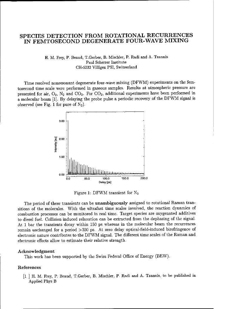
SPECIES DETECTION FROM ROTATIONAL RECURRENCES IN FEMTOSECOND DEGENERATE FOUR-WAVE MIXING
H. M. Prey, P. Beaud, T.Gerber, B. Mischler, P. Radi and A. Tzannis Paul Scherrer Institute
CH-5232 Villigen PSI, Switzerland
Time resolved nonresonant degenerate four-wave mixing (DFWM) experiments on the fem- tosecond time scale were performed in gaseous samples. Results at atmospheric pressure are presented for air, 02, N2 and C02. For C02, additional experiments have been performed in a molecular beam [1]. By delaying the probe pulse a periodic recovery of the DFWM signal is observed (see Fig. 1 for pure of N2).
3.00
1.00
o.oo mm w UWJUMJWLJJUUJJJ*LJUMJUL LJULUJJUXAJU
0.0 50.0 100.0 Delay [ps]
150.0 200.0
Figure 1: DFWM transient for N2
The period of these transients can be unambiguously assigned to rotational Raman tran- sitions of the molecules. With the ultrafast time scales involved, the reaction dynamics of combustion processes can be monitored in real time. Target species are oxygenated additives to diesel fuel. Collision induced relaxation can be extracted from the dephasing of the signal. At 1 bar the transients decay within 150 ps whereas in the molecular beam the recurrences remain unchanged for a period >300 ps. At zero delay optical-field-induced birefringence of electronic nature contributes to the DFWM signal. The different time scales of the Raman and electronic effects allow to estimate their relative strength.
Acknowledgment This work has been supported by the Swiss Federal Office of Energy (BEW).
References
[1 ] H. M. Frey, P. Beaud, T.Gerber, B. Mischler, P. Radi and A. Tzannis, to be published in Applied Phys B
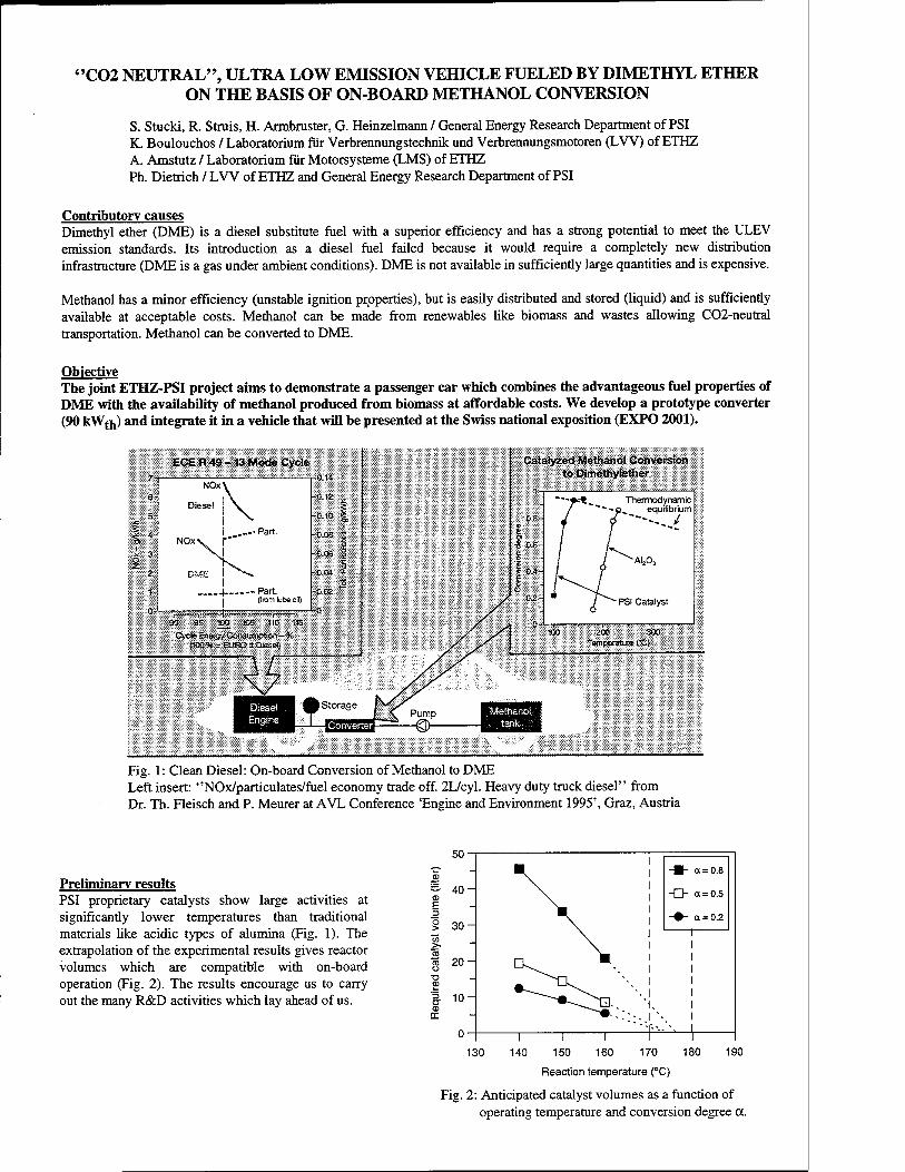
"C02 NEUTRAL", ULTRA LOW EMISSION VEHICLE FUELED BY DIMETHYL ETHER ON THE BASIS OF ON-BOARD METHANOL CONVERSION
S. Stucki, R. Struis, H. Armbruster, G. Heinzelmann / General Energy Research Department of PSI K. Boulouchos / Laboratorium für Verbrennungstechnik und Verbrennungsmotoren (LVV) of ETHZ A. Amstutz / Laboratorium für Motorsysteme (LMS) of ETHZ Ph. Dietrich / LVV of ETHZ and General Energy Research Department of PSI
Contributory causes Dimethyl ether (DME) is a diesel substitute fuel with a superior efficiency and has a strong potential to meet the ULEV emission standards. Its introduction as a diesel fuel failed because it would require a completely new distribution infrastructure (DME is a gas under ambient conditions). DME is not available in sufficiendy large quantities and is expensive.
Methanol has a minor efficiency (unstable ignition properties), but is easily distributed and stored (liquid) and is sufficiently available at acceptable costs. Methanol can be made from renewables like biomass and wastes allowing C02-neutral transportation. Methanol can be converted to DME.
Objective The joint ETHZ-PSI project aims to demonstrate a passenger car which combines the advantageous fuel properties of DME with the availability of methanol produced from biomass at affordable costs. We develop a prototype converter (90 kWt}i) and integrate it in a vehicle that will be presented at the Swiss national exposition (EXPO 2001).
ECE R 49 -13 Mode Cycle Catalyzed Methanol Conversion to Dimethylether
Thermodynamic equilibrium
Fig. 1: Clean Diesel: On-board Conversion of Methanol to DME Left insert: "NOx/particulates/fuel economy trade off. 2L/cyl. Heavy duty truck diesel" from Dr. Th. Fleisch and P. Meurer at AVL Conference 'Engine and Environment 1995', Graz, Austria
Preliminary results PSI proprietary catalysts show large activities at significantly lower temperatures than traditional materials like acidic types of alumina (Fig. 1). The extrapolation of the experimental results gives reactor volumes which are compatible with on-board operation (Fig. 2). The results encourage us to carry out the many R&D activities which lay ahead of us.
130 140 150 160 170
Reaction temperature (°C)
180 190
Fig. 2: Anticipated catalyst volumes as a function of operating temperature and conversion degree a.
Urea-SCR: The promising Aftertreatment Technique to Reduce NO^-Emissions
M. Koebel, M. Elsener, M. Kleemann, Paul Scherrer Institute, CH-5232 Villigen PSI
The selective catalytic reduction process with urea as selective reducing agent has been studied at PSI during the last years. The overall reaction for NO follows a 2:1 stoichiometry:
4 NO + 2 NH.-CO-NH, + 02 -» 4^ + 41^0 + 2 00,
In a first period of the program (1989-1995) the basic properties of the process were investigated in laboratory experiments and on a diesel test stand. The main objective of these experiments was to show the feasibility of DeNOx at stationary diesel engines used in small cogeneration plants. It was shown that no secondary emissions arise if the process is carried out properly. The main secondary emission is ammonia at overdosage of urea. These results were very promising and were further supplemented by the encouraging experience gained in commercial DeNOx installations using urea-SCR.
In a new program period emphasis has been placed on the reduction of NO^-emissions from mobile diesel engines, especially heavy duty vehicles like trucks. Their contribution to global N0X emis- sions is rising constantly and an effective mitigation technology would have a worldwide impact. The key issues to be addressed when urea-SCR is applied to instationary diesel engines are:
a) Reduce the necessary catalyst volumes, i.e. increase the space velocities (GHSV) in the catalyst. This calls for more active catalysts.
b) Reduce the ammonia storage properties of the catalyst. Standard extruded SCR catalysts are based on Ti02-W03-V2Os and show a strongly temperature dependent ammonia storage. At sud- den load/temperature increase of the engine this usually leads to high ammonia emission peaks.
c) Develop an open or closed loop control for the automatic addition of urea. Such a control system must be fast enough to follow fast load changes of a driving cycle.
At PSI we have focused mainly on the first two points both calling for a substantial improvement of the catalysts. The activity may be increased by modifying the preparation procedure and the cataly- tically active components of the catalyst. The ammonia storage properties are reduced by replacing bulk extruded catalysts by coated layer-type catalysts with less active mass. However, as has been shown by model calculations and by tests performed on the catalysts developed, reduced active mass leads to decreased performance at lower temperatures.
It should be born in mind that the activity of a typical catalyst is strongly temperature dependent. On the other hand the range of diesel exhaust temperatures is wide (typically from 150 to 650°C). The development of a suitable catalyst therefore requires a compromise particularly if activity at the lowest temperatures is desired. A catalyst highly active at low temperatures may lead to new problems at higher temperatures, e.g. the formation of N20 or NO. It will therefore be necessary to fix a lower temperature limit where the SCR system is operated, which is estimated to be =280°C. This temperature is reasonable for heavy duty vehicles, but not for passenger cars (due to their oversized engines and corresponding lower average exhaust gas temperatures). New catalysts should allow to increase the maximum GHSV from the previous =10000 h'1 to =60000 h"1 with a corresponding reduction of the catalyst volume by a factor of 6. A 10 dm3 HDV engine with a ma- ximum power output of =325 kW would then require a catalyst volume of 25 dm3.

List of Participants
LIST OF PARTICIPANTS (as per April 16th, 1998)
Roland ALDER Wärtsüä NSD Switzerland Ltd. Postfach 414 Zürcherstr. 12 CH-8401 Winterthur Switzerland Tel.: +41-52-262 4988 Fax: +41-52-262 0724 E-Mail: [email protected]
Sven ANDERSSON Dept. of Thermo- and Fluid Dynamics Chalmers University of Technology S-41296 Göteborg Sweden Tel.: +46-31-772 5033 Fax: +46-31-180 976 E-Mail: [email protected]
C. ARCOUMANIS Department of Mechanical Engineering Imperial College of Science, Technology & Medicine Exhibition Road London SW7 28X U.K. Tel.: +44-171-594 7136 Fax: +44-171-823 8845 E-Mail: [email protected]
Heide ARMBRUSTER Paul Scherrer Institut CH-5232 Villigen PSI Switzerland Tel.: +41-56-310 2137 Fax: +41-56-310 2199 E-Mail: [email protected]
Rik BAERT Eindhoven University of Technology DenOolech2 P.O. Box 513 NL-5600MB Eindhoven The Netherlands Tel.: +31-40-247 2140 Fax: +31-40-243 3445 E-Mail: [email protected]
Christian BARBA EP/MPM Daimler-Benz AG HPC D604 D-70546 Stuttgart Germany Tel.: +49-711-17 59355 Fax: +49-711-17 34078 E-Mail: [email protected] benz.com
Thierry BARITAUD Techniques dApplications Energetiques Institut Frangais du Petrole IFP 1 et 4 Av. de Bois-Preau - BP 311 F-92506 Rueil-Malmaison France Tel.: +33-1-4752 6688 Fax: +33-1-4752 7068(5201) E-Mail: [email protected]
Hardo BARTHS Institut für Technische Mechanik ITM, RWTH Aachen Templergraben 64 D-52056 Aachen Germany Tel.: +49-24180 75 89 Fax: +49-24188 88 223 E-Mail: [email protected]
R. BASTIAANS Eindhoven University of Technology Den Oolech 2 P.O. Box 513 NL-5600MB Eindhoven The Netherlands Tel.: +31-40-247 4836 Fax: +31-40-243 3445 E-Mail: [email protected]
Peter BAUMGARTNER Wärtsüä NSD Switzerland Ltd. Postfach 414 Zürcherstr. 12 CH-8401 Winterthur Switzerland Tel.: +41-52-262 2347 Fax: +41-52-262 0724 E-Mail: [email protected]
Michel BEAUJEAN Director of R&D Lambiotte & Cie S. A. Avenue Des Aubepines 18 B-1180 Brussels Belgium Tel.: +32-2-374 4465 Fax: +32-2-375 3155
Angelo BERNASCONI Dip. Territorio Uff. Prot. Aria Viale St. Franscini 17 CH-6500 Bellinzona Switzerland Tel.: +41-91-804 3738 Fax: +41-91-804 3736 E-Mail: [email protected]
Klaus BINDER Dept. M/EGT Daimler-Benz AG D-70546 Stuttgart Germany Tel.: +49-711-17 22894 Fax: +49-711-17 54356
Erich BLÜMCKE Abteilung I/EK-92 Audi AG D-85045 Ingolstadt Germany Tel.: +49-841-89 5107 Fax: +49-841-89 5018 E-Mail: [email protected]
Clemens BÖGERSHAUSEN EP/MPM Daimler-Benz AG HPC D604 D-70546 Stuttgart Germany Tel.: +49-711-17 54326 Fax: +49-711-17 34078
Konstantinos BOULOUCHOS Inst, für Energietechnik/LW ETH-Zentrum ML K21 Sonneggstr. 3 CH-8092 Zürich Switzerland Tel.: +41-1-632 5648 Fax: +41-1-632 1102 E-Mail: [email protected]
David BRITTON OBMF/52 Shell Centre SHELL International SHELL Centre London SEI 7NA U.K. Tel.: +44-171-934 3758 Fax: +44-171-934 6014 E-Mail: [email protected]
Jan CERWINSKI Automobiltechn. Abt. Abgasprüfstelle Ingenieurschule Biel Gwerdstrasse 5 CH-2560 Nidau Switzerland Tel.: +41-32-3316426 Fax: +41-32-3315934
N.J. DAM Applied Physics University of Nijmegen Toernooiveld P.O. Box 9010 NL-6525ED Nijmegen The Netherlands Tel.: +31-24-365 3016 Fax: +31-24-365 3311 E-Mail: [email protected]
Svenja EINECKE Physikalisch-Chemisches Institut Universität Heidelberg Im Neuenheimer Feld 253 D-69120 Heidelberg Germany Tel.: +49-6221-54 4936 Fax: +49-6221-54 4255 E-Mail: [email protected] heidelberg.de
Andrea FISCHER-REEDMANN Luftfremdstoffe/Umwelttechnik EMPA Überlandstrasse 129 CH-8600 Dübendorf Switzerland Tel.: +41-1-823 4659/5511 Fax: +41-1-8216244 E-Mail: [email protected]
Christian FREI NAW Nutzfahrzeuggesellschaft Schlossgasse 2 CH-9320 Arbon Switzerland Tel.: +41-71-447 1257 Fax: +41-71-447 1391
Thomas GERBER Paul Scherrer Institut CH-5232 Villigen PSI Switzerland Tel.: +41-56-310 2475 Fax: +41-56-310 2199 E-Mail: [email protected]
Peter GLATZ ECO PHYSICS AG Postfach 282 CH-8635 Dürnten Switzerland Tel.: +41-55-240 4343 Fax: +41-55-240 8585 E-Mail: [email protected]
Guido HEINZELMANN Paul Scherrer Institut CH-5232 Villigen PSI Switzerland Tel.: +41-56-310 2615 Fax: +41-56-310 2199 E-Mail: [email protected]
Hans Joachim HELML Advanced Manufacturing Director Lucas Diesel Systems 20/26, bid. du pare lie de la Grande Jatte F-92521 Neuilly sur Seine cedex France Tel.: +33-1-55 62 60 25 Fax: +33-1-55 62 60 02 E-Mail: [email protected]
Christoph HOELLE Abt. ZM-E-23 BMW Motoren GmbH Hinterbergerstrasse 2 A-4400 Steyr Austria Tel.: +43-7252 888 3572 Fax: +43-7252 8886 3572 E-Mail: [email protected]
Rudolf HOLTBECKER R&D KoSt 7055 Wärtsilä NSD Switzerland Ltd. Postfach 414 CH-8401 Winterthur Switzerland Tel.: +41-52-262 4464 Fax: +41-52-262 0725 E-Mail: [email protected]
Walter HUBSCHMID Paul Scherrer Institut CH-5232 Villigen PSI Switzerland Tel.: +41-56-310 2938 Fax: +41-56-310 2199 E-Mail: [email protected]
B. INEICHEN Institut für Energietechnik LW ETH-Zentrum MLK20 CH-8092 Zürich Switzerland Tel.: +41-1-632 3656 Fax: +41-1-632 1102 E-Mail: [email protected]
Moni ISLAM Abteilung I/EK-92 Audi AG D-85045 Ingolstadt Germany Tel.: +49-841-89 5107 Fax: +49-841-89 5018 E-Mail: [email protected]
Laurentius JÄGER Inst, für Energietechnik/LVV ETH-Zentrum CH-8092 Zürich Switzerland Tel.: +41-1-632 5016 Fax: +41-1-6321102 E-Mail: [email protected]
Daniel JERMANN Duap AG Waldgasse 19 CH-3360 Herzogenbuchsee Switzerland Tel.: +41-62-9616565 Fax: +41-62-9616110
Frank KELLER FT1/TV Daimler Benz AG HPC: G 212 D-70546 Stuttgart Germany Tel.: +49-711-17 53915 Fax: +49-711-17 55579 E-Mail: [email protected]
Manfred KOEBEL Paul Scherrer Institut CH-5232 ViUigenPSI Switzerland Tel.: +41-56-310 2604 Fax: +41-56-310 2199 E-Mail: [email protected]
Christian KRÜGER Daimler Benz AG HPC: E222 D-70546 Stuttgart Germany Tel.: +49-711-17 21532 Fax: +49-711-17 52416 E-Mail: [email protected]
Stefan KUNTE Inst, für Energietechnik/LW ETH-Zentrum CH-8092 Zürich Switzerland Tel.: +41-1-632 4976 Fax: +41-1-632 1102 E-Mail: [email protected]
Jacques LEMAIRE Automotive Depollution RHODIA Rare Earths&Gallium 25 Quai Paul Doumer F-92408 Courbevoie cedex 29 France Tel.: +33-1-4768 1654 Fax: +33-1-4768 0400
Thomas LUTZ Inst, für Energietechnik/LW ETH-Zentrum CH-8092 Zürich Switzerland Tel.: +41-1-632 2482 Fax: +41-1-6321102 E-Mail: [email protected]
Willi MAHLER W. Mahler AG Bachstrasse 27 CH-8912 Obfelden Switzerland Tel.: +41-1-7614191 Fax: +41-1-7614458
W. L. MEERTS Dept. of Molecular + Laser Physics University of Nijmegen Toernooiveld P.O. Box 9010 NL-6500GL Nijmegen The Netherlands Tel.: +31-24-365 3023 Fax: +31-24-365 3311 E-Mail: [email protected]
Xavier MONTAGNE Institut Francais du Petrole 1 et 4, avenue de Bois-Preau, B.P. 311 F-92506 Rueil-Malmaison cedex France Tel.: +33-1-4752 6098/6801 Fax: +33-1-4752 7000 E-Mail: [email protected]
Verena MOSER AA/FFA Ford Forschungszentrum Aachen Dennewartstr. 25 Technologiezentrum am Europaplatz D-52068 Aachen Germany Tel.: +49-241-9421 125 Fax: +49-241-9421 301 E-Mail: [email protected]
William MUSTEL Automotive Emissions Control RHODIA Terres Rares & Galhum 25 Quai Paul Doumer F-92408 Courbevoie France Tel.: +33-1-4768 1654 Fax: +33-1-4768 0400 E-Mail: [email protected]
Christian NELLEN Inst, für Energietechnik/LW ETH-Zentrum ML J 41.3 Sonneggstr. 3 CH-8092 Zürich Switzerland Tel.: +41-1-632 7534 Fax: +41-1-632 1177 E-Mail: [email protected]
Tommy NORSTRÖM Combustion Chemistry Research Group ABO Akademi University Lemmihkaisenkatu 14-18B SF-20520 Turku Finland Tel.: +358 2215 4932 Fax: +358 2215 4780 E-Mail: [email protected]
Edwin OTT Advanced Technology Diesel Gumpenwiesen 14 Postfach 156 CH-8157 Dielsdorf Switzerland Tel.: +41-1-853 3495 Fax: +41-1-853 3495
Thiebault PÄQUET Toyota Motor Europe, Technical Centre Hoge Wei 33A B-1930 Zaventem Belgium Tel.: +32-2-712 3227 Fax: +32-2-712 3256 E-Mail: [email protected]
Norbert PETERS Institut für Technische Mechanik ITM, RWTH Aachen Templergraben 64 D-52056 Aachen Germany Tel.: +49-241 80 4609/4616 Fax: +49-2418888 223 E-Mail: [email protected]
Horst PRILOP EP/MPM Daimler-Benz AG HPC D604 D-70546 Stuttgart Germany Tel.: +49-711-17 50087 Fax: +49-711-17 34078
Bernd REINAUER NAW Nutzfahrzeuggesellschaft Schlossgasse 2 CH-9320 Arbon Switzerland Tel.: +41-71-447 1257 Fax: +41-71-447 1391
Bruno SCHNEIDER Inst, für Energietechnik/LW ETH-Zentrum CH-8092 Zürich Switzerland Tel.: +41-1-632 7992 Fax: +41-1-632 1102 E-Mail: [email protected]
Raffael SCHUBIGER Inst, für Energietechnik/LW ETH-Zentrum ML/J15 CH-8092 Zürich Switzerland Tel.: +41-1-632 4824 Fax: +41-1-632 1102 E-Mail: [email protected]
Christof SCHULZ Physikalisch-Chemisches Institut Universität Heidelberg Im Neuenheimer Feld 253 D-69120 Heidelberg Germany Tel.: +49-6221-548503 Fax: +49-6221-544255 E-Mail: [email protected] heidelberg.de
ErikSCHÜNEMANN Lehrstuhl für Technische Thermodynamik Universität Erlangen-Nürnberg Am Weichselgarten 8 D-91058 Erlangen Germany Tel.: +49-9131-85 9775 Fax: +49-9131-85 9901 E-Mail: [email protected] erlangen.de
Rob SMITH G. G. M. STOFFELS Project Management Director Dept. of Molecular + Laser Physics Lucas Diesel Systems University of Nijmegen 26 Bid du Par - He de la Jatte Toernooiveld 1 F-92521 Neuilly sur Seine NL-6525ED Nijmegen France The Netherlands Tel.: +33-155 62 6036 Tel.: +31-24-365 3017 Fax: +33-155 62 6004 Fax: +31-24-365 3311
E-Mail: [email protected] Bart SOMERS Eindhoven University of Technology Tim STRAUSS DenOolech2 P.O. Box 513 EAS-Motorberechnung 1762 NL-5600MB Eindhoven Volkswagen AG The Netherlands D-38436 Wolfsburg Tel.: +31-40-247 2107 Germany Fax: +31-40-243 3445 Tel.: +49-5362 122 E-Mail: [email protected] Fax: +49-5362 267
E-Mail: [email protected] C. M. I. SPAANJAARS Dept. of Molecular + Laser Physics Rudolf STRUIS University of Nijmegen Paul Scherrer Institut Toernooiveld P.O. Box 9010 CH-5232 Villigen PSI NL-6500GL Nijmegen Switzerland The Netherlands Tel.: +41-56-310 4169 Tel.: +31-24-365 3017 Fax: +41-56-310 2199 Fax: +31-24-365 3311 E-Mail: [email protected] E-Mail: [email protected]
Gerrit SUCK Tobias STEINER Konzernforschung K-EFE Inst, für Energietechnik/LW Volkswagen AG Wolfsburg ETH-Zentrum Postfach 1776 CH-8092 Zürich D-38436 Wolfsburg Switzerland Germany Tel.: +41-1-632 4618 Tel.: +49-5361-97 55 16 Fax: +41-1-632 1102 Fax: +49-5361-97 28 37 E-Mail: [email protected]
Franz TANNER Gunnar STIESCH I.C. Engines and Combustion Laboratory ITV Institut für Technische Verbrennung ETHZ, CLT-F1 Universität Hannover Clausiusstrasse 33 Weifengarten 1A CH-8092 Zürich D-30167 Hannover Switzerland Germany Tel.: +41-1-632 4619 Tel.: +49-511-762 4396 Fax: +41-1-632 1255 Fax: +49-511-762 2530 E-Mail: [email protected] E-Mail: [email protected]
Hans TER MEULEN Dept. of Molecular + Laser Physics University of Nijmegen Toernooiveld 1 NL-6525ED Nijmegen The Netherlands Tel.: +31-24-365 3022 Fax: +31-24-365 3311 E-Mail: [email protected]
6
Nassia TZELEPI afdeling B-faculteiten, toegepaste fysica Katholieke Universiteit Nijmegen Toernooiveld 1 NL-6525ED Nijmegen The Netherlands Tel.: +31-24-365 3017 Fax: +31-24-365 3311 E-Mail: [email protected]
Bianca Maria VAGLIECO Fluid Dynamics + Combustion Div. Istituto Motori - CNR 8, via Marconi 1-80125 Napoli Italia Tel.: +39-81-7177 127 Fax: +39-81-239 6097 E-Mail: [email protected]
Erik-Jan VAN DEN BOOM Dept. of Molecular + Laser Physics University of Nijmegen Toernooiveld 1 NL-6525ED Nijmegen The Netherlands Tel.: +31-24-365 3017 Fax: +31-24-365 3311 E-Mail: [email protected]
Jacques VANDOOREN Laboratoire de Physico-Chimie de la Combustion Universite Catholique de Louvain 1, pi. Louis Pasteur B-1348 Louvain-la-Neuve Belgium Tel.: +32-10 47 2727/61 Fax: +32-10 47 2468 E-Mail: [email protected]
Alexander WOKAUN Paul Scherrer Institut CH-5232 Villigen PSI Switzerland Tel: +41-56-310 2751 Fax: +41-56-310 4416 E-Mail: [email protected]
E. E. WOLFF Director, Internatl. R&D CATERPILLAR Inc. Technical Center P. O. Box 1875 Peoria, Illinois 61656 USA Tel.: +1-309-578-8796 Fax: +1-309-578-4484
Lisa I. YEH ESSO Research Centre Abingdon Oxfords. OC13 6AE G.B. Tel.: +44-1235-54 5049 Fax: +44-1235-54 5044 E-Mail: [email protected]
Marian ZABLOCKI Institute of Petroleum Processing ul. Lukasiewicz a 1 31-429 Krakow Poland Tel.: +48-12-6177 528 Fax: +48-12-6114462
Peter VON BÖCKH Fachhochschule beider Basel FHBB Grundenstr. 40 CH-4132 Muttenz Switzerland Tel.: +41-61-467 4276 Fax: +41-61-467 4460 E-Mail: [email protected]