Embed Size (px)
Citation preview
Towards catheter tracking and data-based cathetersteering
Bingbin Yu, Abraham T. Tibebu, Jan Hendrik MetzenUniversity of Bremen
Robotics Research GroupRobert-Hooke-Strasse 5, D-28359 Bremen, Germany
Email: [email protected]
Emmanuel Vander PoortenUniversity of Leuven
Dept. of mechanical engineering, division PMACelestijnenlaan 300B, B-3001 Heverlee, Belgium
Abstract—Minimally invasive surgery (MIS) is an importantapproach for reducing injuries of the body, allowing fasterrecovery and healing, and is considered to be safer than opensurgeries. Especially for the cardiovascular operations, catheterbased diagnosis and therapy are becoming more popular thesedays. This paper presents an approach of tendon-driven cathetersteering by using a joint probability density based catheter model.For tracking the catheter in a 3D rigid mockup, a Qualisys motiontracking system is used. The catheter steering is evaluated insimulation on a mesh generated from the real CT image data.
I. EXPERIMENTAL SETUP
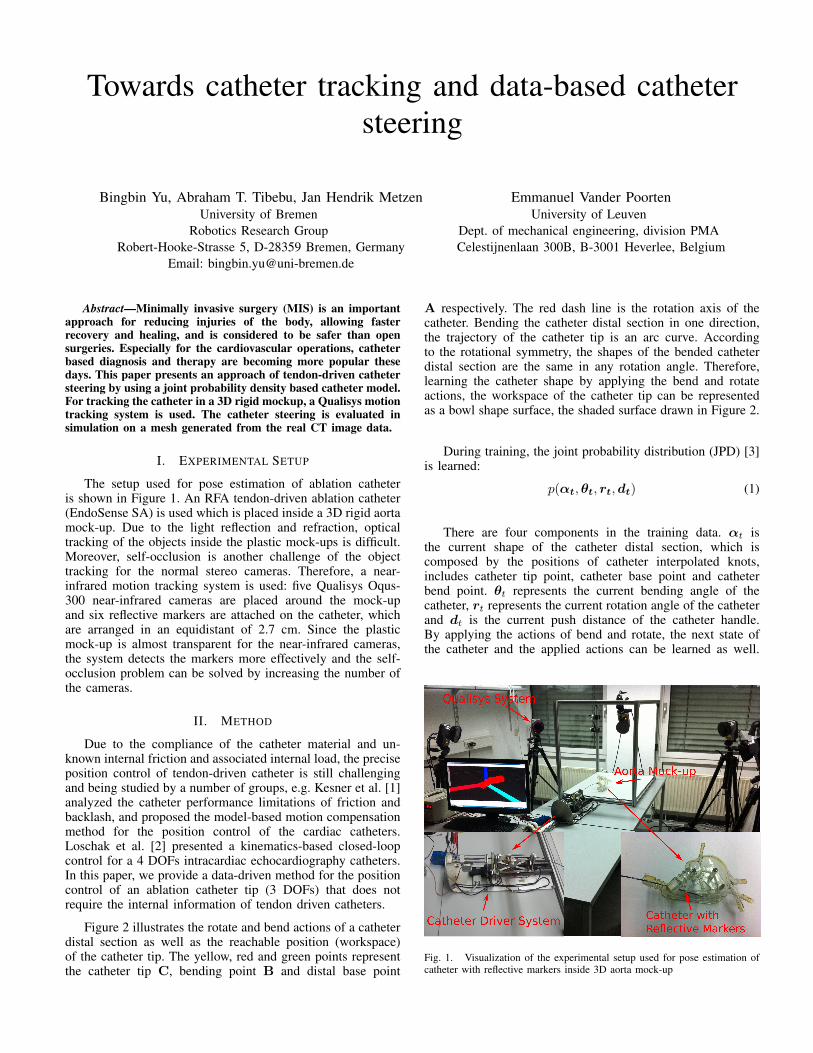
The setup used for pose estimation of ablation catheteris shown in Figure 1. An RFA tendon-driven ablation catheter(EndoSense SA) is used which is placed inside a 3D rigid aortamock-up. Due to the light reflection and refraction, opticaltracking of the objects inside the plastic mock-ups is difficult.Moreover, self-occlusion is another challenge of the objecttracking for the normal stereo cameras. Therefore, a near-infrared motion tracking system is used: five Qualisys Oqus-300 near-infrared cameras are placed around the mock-upand six reflective markers are attached on the catheter, whichare arranged in an equidistant of 2.7 cm. Since the plasticmock-up is almost transparent for the near-infrared cameras,the system detects the markers more effectively and the self-occlusion problem can be solved by increasing the number ofthe cameras.
II. METHOD
Due to the compliance of the catheter material and un-known internal friction and associated internal load, the preciseposition control of tendon-driven catheter is still challengingand being studied by a number of groups, e.g. Kesner et al. [1]analyzed the catheter performance limitations of friction andbacklash, and proposed the model-based motion compensationmethod for the position control of the cardiac catheters.Loschak et al. [2] presented a kinematics-based closed-loopcontrol for a 4 DOFs intracardiac echocardiography catheters.In this paper, we provide a data-driven method for the positioncontrol of an ablation catheter tip (3 DOFs) that does notrequire the internal information of tendon driven catheters.
Figure 2 illustrates the rotate and bend actions of a catheterdistal section as well as the reachable position (workspace)of the catheter tip. The yellow, red and green points representthe catheter tip C, bending point B and distal base point
A respectively. The red dash line is the rotation axis of thecatheter. Bending the catheter distal section in one direction,the trajectory of the catheter tip is an arc curve. Accordingto the rotational symmetry, the shapes of the bended catheterdistal section are the same in any rotation angle. Therefore,learning the catheter shape by applying the bend and rotateactions, the workspace of the catheter tip can be representedas a bowl shape surface, the shaded surface drawn in Figure 2.
During training, the joint probability distribution (JPD) [3]is learned:
p(αt,θt, rt,dt) (1)
There are four components in the training data. αt isthe current shape of the catheter distal section, which iscomposed by the positions of catheter interpolated knots,includes catheter tip point, catheter base point and catheterbend point. θt represents the current bending angle of thecatheter, rt represents the current rotation angle of the catheterand dt is the current push distance of the catheter handle.By applying the actions of bend and rotate, the next state ofthe catheter and the applied actions can be learned as well.
Fig. 1. Visualization of the experimental setup used for pose estimation ofcatheter with reflective markers inside 3D aorta mock-up

Fig. 2. The catheter steering mechanism and the corresponding bowl shapedcatheter tip workspace.
Therefore, the JPD model is represented:
p(αt+1,θt+1, rt+1,dt+1,αt,θt, rt,dt, δd, δr) (2)
Since the tendon-driven catheter is used, the bend action isrepresented by a displacement of the catheter handle δd andδr represents rotate action.
In the test, based on the current catheter shape αt and theevery avaliable actions δ∗d, δ
∗r, the workspace of the catheter
tip can be estimated based on the model.
E[p∗t+1|αt,θt, rt,dt, δ
∗d, δ
∗r
](3)
p∗t+1 is the workspace of the catheter tip. Therefore, Thecrossing point between the planned trajectory and catheter tipworkspace can be calculated as the reference position and thecorresponding actions are the actions for steering the catheter.Further details are given by Yu et al. [4].
III. RESULTS
Before estimating the catheter pose, the accuracy of thecamera system is evaluated by a simple experiment. In thetest, two reflective markers are mounted on a rigid bar with adistance of 30 cm to each other. The bar is moved in the testbedarea and the markers are detected by the Qualisys system. Thedistance between the two markers is captured by the camerasystem in 720 different image frames, which is the estimateddistance. The standard deviation of the real distance and theestimated distance of these two markers is calculated, whichreaches 0.4213mm.
Since the aorta mesh is given in a simulation coordinatesystem, whereas the catheter is captured in the camera coor-dinate system, a registration step is required to transform thecatheter into simulation coordinate system. For calculating theregistration matrix, seven reflective markers are attached onthe feature positions of 3D real aorta mock-up. By registeringthe detected feature points from real aorta mock-up to thevirtual aorta mock-up in simulation, the catheter pose can bepresented in the simulation enviroment as Figure 3 shows.The six reflective markers which are attached on the ablationcatheter are detected and presented as the red dots in the aorta
Fig. 3. The pose estimation using Qualisys system: Catheter spline is shownin green, all six of the reflective markers are shown with red dot.
mesh. The green curve is the catheter shape which is calculatedby the B-spline curve fitting method.
For evaluating the catheter steering, an autonomous trajec-tory following experiment is conducted by using a cathetersimulator. The simulator includes both a 3D aorta meshrepresenting the enviroment and a simulated catheter. Forreducing the risk of catheter steering in the cardiovascularsystem, a trajectory for the catheter tip in the aorta mainbranch is planned, which keeps largest distance to the detectedcalcification areas from the real preoperative data. The catheteris inserted into the aorta mesh with 2mm translation steps,based on the catheter steering algorithm, the correspondingactions are generared and the catheter tip is steered towards thetrajectory autonomously. Figure 4 shows the planned trajectoryand the catheter tip position during the trajectory followingtest. The mean Euclidean distance from the catheter tip to thetrajectory is 4.09mm.
Due to the interaction between the catheter and the aortavessel has not been included into the model yet, the cathetertip could not follow the planned trajectory smoothly. Thereforein the near future, we will focus on extending our model withthe catheter-aorta interaction. In addition to this, safe trajectoryfollowing in a real 3D experimental setup (shown in Figure 1)by using the Qualisys system and a catheter drive system willbe realized.
ACKNOWLEDGMENT
This research has been funded by the EuropeanCommission’s 7th Framework Programme FP7-ICT, bythe project CASCADE under grant agreement No.601021.
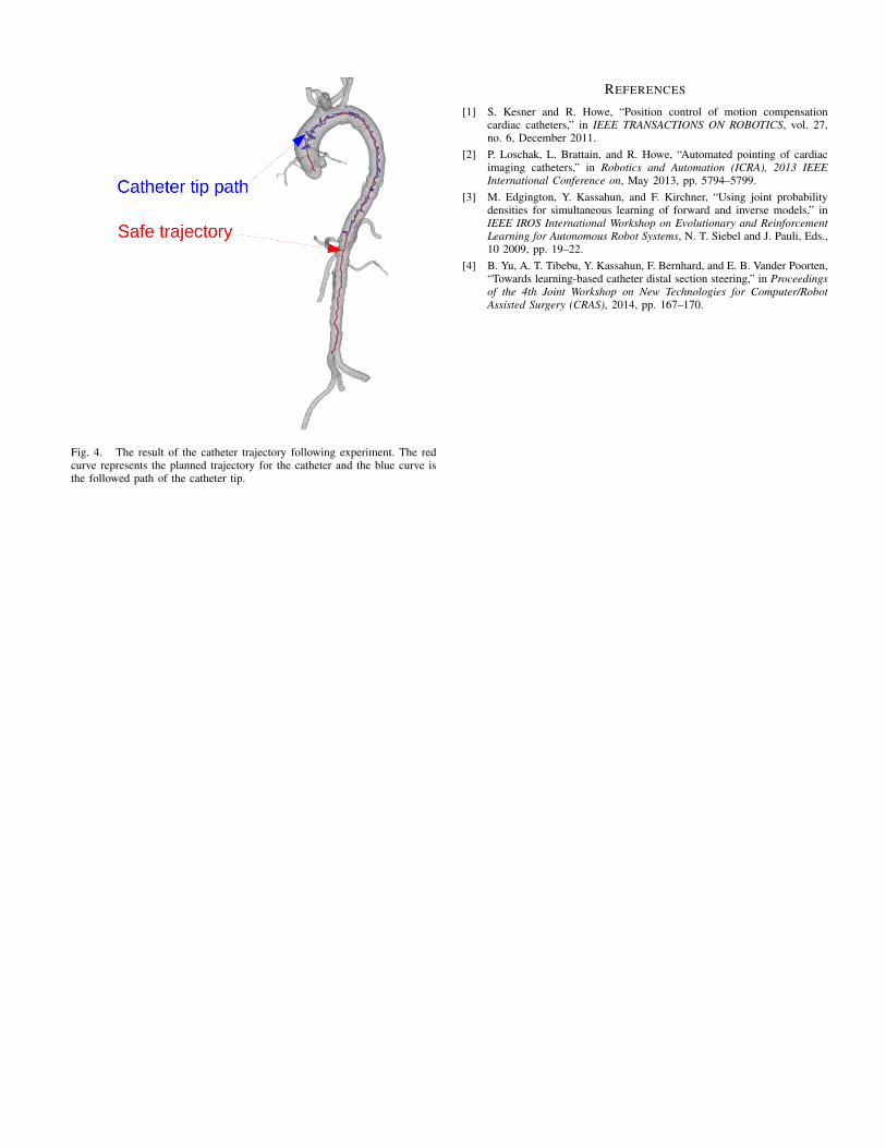
Fig. 4. The result of the catheter trajectory following experiment. The redcurve represents the planned trajectory for the catheter and the blue curve isthe followed path of the catheter tip.
REFERENCES
[1] S. Kesner and R. Howe, “Position control of motion compensationcardiac catheters,” in IEEE TRANSACTIONS ON ROBOTICS, vol. 27,no. 6, December 2011.
[2] P. Loschak, L. Brattain, and R. Howe, “Automated pointing of cardiacimaging catheters,” in Robotics and Automation (ICRA), 2013 IEEEInternational Conference on, May 2013, pp. 5794–5799.
[3] M. Edgington, Y. Kassahun, and F. Kirchner, “Using joint probabilitydensities for simultaneous learning of forward and inverse models,” inIEEE IROS International Workshop on Evolutionary and ReinforcementLearning for Autonomous Robot Systems, N. T. Siebel and J. Pauli, Eds.,10 2009, pp. 19–22.
[4] B. Yu, A. T. Tibebu, Y. Kassahun, F. Bernhard, and E. B. Vander Poorten,“Towards learning-based catheter distal section steering,” in Proceedingsof the 4th Joint Workshop on New Technologies for Computer/RobotAssisted Surgery (CRAS), 2014, pp. 167–170.


![Grasping Using Magnetically-Actuated Tentacle Catheter: A ... · solution to these problems [6]. Several studies have already demonstrated steering of magnetically-actuated catheters](https://img.pdfslide.us/doc/110x75/5f9ad7773511e84af02088a5/grasping-using-magnetically-actuated-tentacle-catheter-a-solution-to-these.jpg)