Embed Size (px)
Citation preview
Towards an industrialisation and standardisation of earthquake isolators: a case study
M. C. Phocas1 & A. Pocanschi2
1Department of Civil and Environmental Engineering, University of Cyprus, Cyprus 2Institute of Structural Systems and Structural Building Design, University of Stuttgart, F.R. Germany
Abstract
Base isolation of buildings has proven over the last years through international research and implementation activities to be mostly promising for earthquake safety. Nevertheless for the practicing engineer all presently available isolator devices are restricted to relatively difficult application procedures due to a lack of supporting frame conditions from the respective national earthquake codes. For enabling an industrialisation, standardisation and economic effectiveness, as regards different isolation needs, seismic sites and vertical loading conditions resulting from the building construction typology, as well as a non special skill demanding construction in conventional low-rise residential buildings, an innovative series of adaptable isolators with a highly flexible set up has been developed. Following the construction development of the isolator the elastic and hysteretic behaviour of prototypes under different vertical loading have been investigated in 1:1 scale in dynamic laboratory tests. Their mechanical properties have been determined and the respective linear-equivalent SDOF systems have been analysed in the time-history range for ten characteristic earthquake components of the Greek Mediterranean region. Keywords: structural control, base isolation, dynamic loading tests, hysteretic behaviour, seismic performance.
© 2005 WIT Press WIT Transactions on The Built Environment, Vol 81, www.witpress.com, ISSN 1743-3509 (on-line)
Earthquake Resistant Engineering Structures V 685
1 Introduction
Structural control through base isolation has proven to be a most promising strategy for earthquake safety of the building. The structure withstands repetitively the ground displacements without undergoing plastic deformations, since the earthquake impacts are picked up and further transferred to the building as smaller, over a longer time span distributed forces. The control technique causes an increase of the period of the structure and a reduction of the earthquake effects on the building. In the frame of the research program on structural control an earthquake isolator series has been developed in the previous years at the University of Stuttgart in cooperation with the firm New York-Hamburger Gummi-Waaren Co. AG. The device exhibits the properties of a rigid bearing as well as of an earthquake isolator with progressive deformation limitation, and is mainly applicable to middle-rise buildings (up to four storeys) and to sites of moderate seismicity (EPA ≤ 0.25g). Decisive for these conditions were the following considerations: - Middle-rise buildings, like residential buildings, schools and hospitals with
up to four storeys make up about 75% of the total building investments worldwide.
- In most countries with high earthquake risk, compact buildings are built due to economic factors in usual concrete and masonry construction. The disregard of elementary earthquake resistance rules leads to catastrophic consequences even during moderate earthquakes. According to statistical analyses the largest losses of human lives from earthquakes occur through the collapse of residential buildings.
- The market suffers from a lack of compact earthquake isolators for low loads of non specialised construction. Presently available devices of laminated elastomeric bearings are difficult to adjust to lower vertical loads. In such cases the necessary horizontal stiffness can only be achieved through the reduction of the section dimensions, not being any more compatible to the stability requirements under ground displacements, Pocanschi and Phocas [1].
2 System parameters
Earthquake isolators should be stable under the design displacement, exhibit increasing resistance with increasing displacement, produce sufficient restoring force, so that the building can return to the original position, be able to withstand repetitively cyclic loads and exhibit a stable characteristic curvature and damping properties, that can be quantified. According to these requirements the following aims were decisive in the development of the isolator: - The limitation of the isolator deformations should be achieved through a
characteristic curvature of a nonlinear, progressive type. - The variation of the stiffness and damping properties of the isolator should be
made possible without change of the basic dimensions.
© 2005 WIT Press WIT Transactions on The Built Environment, Vol 81, www.witpress.com, ISSN 1743-3509 (on-line)
686 Earthquake Resistant Engineering Structures V
- The isolator should obtain in compact form all necessary elements for the vertical load bearing, an adequate initial stiffness for the wind loads and the provision of isolation and damping under earthquake loads. Additionally it should be protected against fire, light and humidity.
- The device should be made simple, robust, mostly light, economic and similarly to bridge bearings, available as catalogue article, that could be also constructed by building personnel without specialised knowledge.
For the determination of the maximum vertical load of the isolator a conventional residential building system is considered; one to four storey buildings with masonry walls and massive storey slabs with a grid of 3.5 x 4.5 m. The total load (self-weight and live loads) for the roof slabs is 5.0 kN/m² and for the intermediate slabs including the walls is 11.0 kN/m². With these values the application of isolators with vertical loads of up to 700 kN seems to be mostly appropriate. The possible vertical load range for the analysis was set at 84 to 910 kN. The period of the isolated building should lie in the “isolation area” of the response spectrum, i.e. T > 1.5 s. For average rigid grounds and a damping ratio of about ζ = 0.1 the maximum displacement of the isolator was set in accordance to [2, 3] at maxU = 10.0 cm.
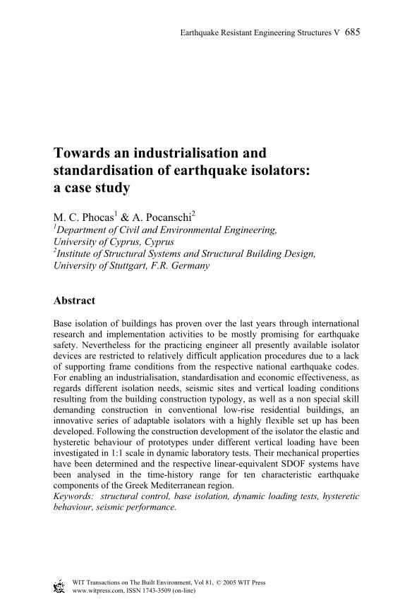
Figure 1: Section view of the earthquake isolator.
3 Construction
The isolator consists of two coupled elements with different mechanical properties: A primary bearing element, responsible for the vertical load transfer and the dynamic isolation and a secondary bearing element, responsible for the displacement control, the unloading of the primary element under large displacements and the provision of additional damping, fig. 1. The primary element is a conventional elastomeric bearing in form of a ring or several columns, placed between two circumferential ring plates, figs 2(a), (b). The secondary element consists of a glass-fibre reinforced epoxy resin ball, embedded in a double concave elastomeric pillow, vulcanised in steel cases, fig. 2(c). The device is protected against fire, contamination and humidity
© 2005 WIT Press WIT Transactions on The Built Environment, Vol 81, www.witpress.com, ISSN 1743-3509 (on-line)
Earthquake Resistant Engineering Structures V 687
through an envelope of fireproof material. The whole device is set within a metal sleeve with a thickness of 2 mm, which ensures the initial stiffness for the wind forces transfer, fig. 2(d).
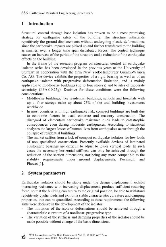
Figure 2: Bearing elements of the isolator; (a) Ring bearing; (b) Column bearing; (c) Ball bearing with lower elastomeric pillow; (d) Metal sleeves.
The ring bearing has an outer diameter of 500 mm, a width of 100 mm and vulcanised setup. It is composed of nine 2 mm thick ring plates and ten 8 mm thick elastomeric sheets. Together with the two 10 mm thick ring endplates the overall height of the bearing is 118 mm. The hardness of the elastomere is 60 Shore degrees. The column bearing consists of four, eight, or twelve laminated elastomeric springs with diameter of 100 mm, placed on the circumference. The springs are composed of twenty 4 mm thick rubber rings of 60 Shore degrees and nineteen 1 mm thick steel plates that together with the two 10 mm thick endplates make up an overall height of 120 mm. The epoxy resin ball of the secondary element has a diameter of 180 mm. The elastomeric pillows of 80 Shore degrees have a basic thickness in the middle of 20 mm, which increases to the rims to 60 mm. At the circumference they are provided with a 15 mm wide and 40 mm deep flute. With an outer diameter of the steel case of 280 mm the diameter of the concavity makes up 230 mm. The inclination angle of the pillows is 22.5°.
© 2005 WIT Press WIT Transactions on The Built Environment, Vol 81, www.witpress.com, ISSN 1743-3509 (on-line)
688 Earthquake Resistant Engineering Structures V
4 Dynamic loading tests
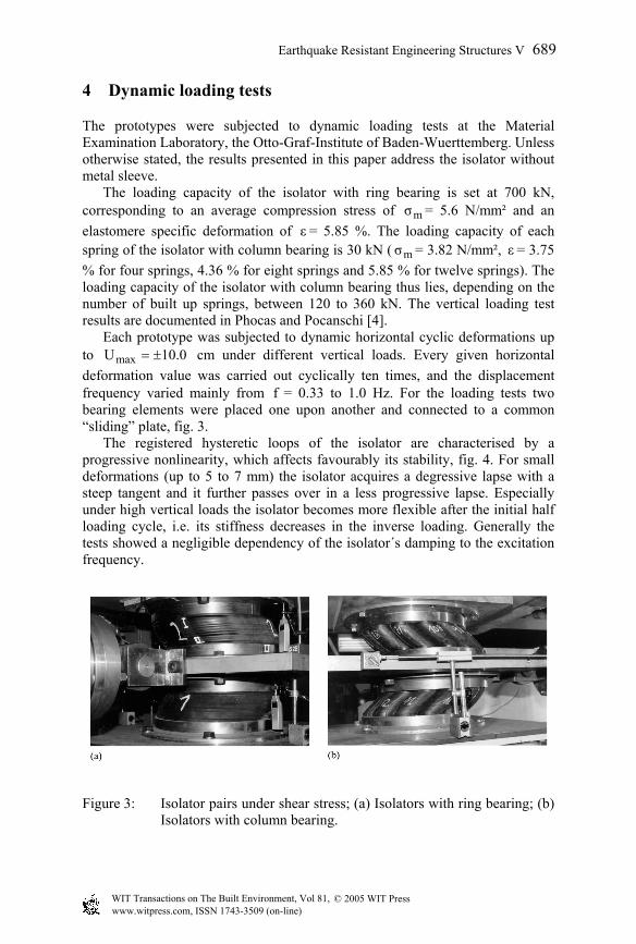
The prototypes were subjected to dynamic loading tests at the Material Examination Laboratory, the Otto-Graf-Institute of Baden-Wuerttemberg. Unless otherwise stated, the results presented in this paper address the isolator without metal sleeve. The loading capacity of the isolator with ring bearing is set at 700 kN, corresponding to an average compression stress of mσ = 5.6 N/mm² and an elastomere specific deformation of ε = 5.85 %. The loading capacity of each spring of the isolator with column bearing is 30 kN ( mσ = 3.82 N/mm², ε = 3.75 % for four springs, 4.36 % for eight springs and 5.85 % for twelve springs). The loading capacity of the isolator with column bearing thus lies, depending on the number of built up springs, between 120 to 360 kN. The vertical loading test results are documented in Phocas and Pocanschi [4]. Each prototype was subjected to dynamic horizontal cyclic deformations up to 0.10Umax ±= cm under different vertical loads. Every given horizontal deformation value was carried out cyclically ten times, and the displacement frequency varied mainly from f = 0.33 to 1.0 Hz. For the loading tests two bearing elements were placed one upon another and connected to a common “sliding” plate, fig. 3. The registered hysteretic loops of the isolator are characterised by a progressive nonlinearity, which affects favourably its stability, fig. 4. For small deformations (up to 5 to 7 mm) the isolator acquires a degressive lapse with a steep tangent and it further passes over in a less progressive lapse. Especially under high vertical loads the isolator becomes more flexible after the initial half loading cycle, i.e. its stiffness decreases in the inverse loading. Generally the tests showed a negligible dependency of the isolator´s damping to the excitation frequency.
Figure 3: Isolator pairs under shear stress; (a) Isolators with ring bearing; (b) Isolators with column bearing.
© 2005 WIT Press WIT Transactions on The Built Environment, Vol 81, www.witpress.com, ISSN 1743-3509 (on-line)
Earthquake Resistant Engineering Structures V 689
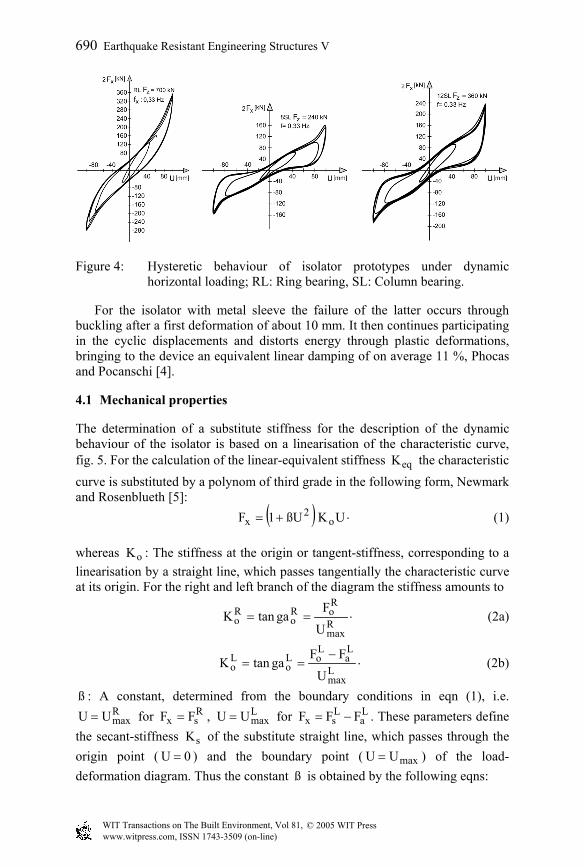
Figure 4: Hysteretic behaviour of isolator prototypes under dynamic horizontal loading; RL: Ring bearing, SL: Column bearing.
For the isolator with metal sleeve the failure of the latter occurs through buckling after a first deformation of about 10 mm. It then continues participating in the cyclic displacements and distorts energy through plastic deformations, bringing to the device an equivalent linear damping of on average 11 %, Phocas and Pocanschi [4].
4.1 Mechanical properties
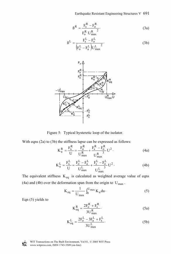
The determination of a substitute stiffness for the description of the dynamic behaviour of the isolator is based on a linearisation of the characteristic curve, fig. 5. For the calculation of the linear-equivalent stiffness eqK the characteristic curve is substituted by a polynom of third grade in the following form, Newmark and Rosenblueth [5]: ( ) ⋅+= UKßU1F o
2x (1)
whereas oK : The stiffness at the origin or tangent-stiffness, corresponding to a linearisation by a straight line, which passes tangentially the characteristic curve at its origin. For the right and left branch of the diagram the stiffness amounts to
⋅== Rmax
RoR
oRo
UF
gatanK (2a)
⋅−
== Lmax
La
LoL
oLo
UFF
gatanK (2b)
ß : A constant, determined from the boundary conditions in eqn (1), i.e. RmaxUU = for R
sx FF = , LmaxUU = for L
aLsx FFF −= . These parameters define
the secant-stiffness sK of the substitute straight line, which passes through the origin point ( 0U = ) and the boundary point ( maxUU = ) of the load-deformation diagram. Thus the constant ß is obtained by the following eqns:
© 2005 WIT Press WIT Transactions on The Built Environment, Vol 81, www.witpress.com, ISSN 1743-3509 (on-line)
690 Earthquake Resistant Engineering Structures V
⋅−
= 2Rmax
Ro
Ro
RsR
UF
FFß (3a)
( )
⋅−
−= 2L
maxLa
Lo
Lo
LsL
UFF
FFß (3b)
Figure 5: Typical hysteretic loop of the isolator. With eqns (2a) to (3b) the stiffness lapse can be expressed as follows:
⋅−
+== 23R
max
Ro
Rs
Rmax
Ro
RxR
u UU
FFUF
UFK (4a)
⋅−
+−
== 23L
max
Lo
Ls
Lmax
La
Lo
LxL
u UU
FFU
FFU
FK (4b)
The equivalent stiffness eqK is calculated as weighted average value of eqns
(4a) and (4b) over the deformation span from the origin to maxU .
⋅= ∫ maxU0 u
maxeq duK
U1K (5)
Eqn (5) yields to
⋅+
= Rmax
Rs
RoR
eqU3
FF2K (5a)
⋅+−
= Lmax
Ls
La
LoL
eqU3
FF3F2K (5b)
© 2005 WIT Press WIT Transactions on The Built Environment, Vol 81, www.witpress.com, ISSN 1743-3509 (on-line)
Earthquake Resistant Engineering Structures V 691
The frequency of the spring-mass system is given with eqns (5a) and (5b) to
⋅
+=
mK
mK
21ω
Leq
Req (6)
The damping ratio ζ and the damping coefficient C can be calculated from the losses work WL within a loading cycle as follows:
⋅=2
maxeq
W
UKπ2
Lζ (7)
⋅=2
max
W
Uπω
LC (8)
The mechanical properties of the isolator under different vertical loads and composition of the primary element are calculated based on the obtained hysteretic loops and eqns (5a) to (8), table 1.
Table 1: Dynamic horizontal analysis results.
Isol.-type
Vertical load
zF [kN]
Eq. stiffness
eqK [kN/cm]
Frequency ω [1/s]
Hyster.-area
WL [kNcm]
Damping ratio ζ
[%]
Damping coefficient
C [kNs/cm]
490 14.39 5.37 538 5.95 0.32 700 12.02 4.10 748 9.91 0.58 RL 910 11.98 3.56 764 10.70 0.72
4SL 84 4.61 7.34 222 7.67 0.10 168 7.44 6.58 473 9.92 0.22 240 6.14 5.01 544 14.11 0.35 8SL 312 4.78 3.88 566 18.86 0.47 252 5.33 4.56 330 9.86 0.23 360 8.72 4.87 718 13.11 0.47 12SL468 7.03 3.83 810 18.72 0.69
5 Time-history analysis
The calculated mechanical properties of the isolator were used in the dynamic analysis in the time-history range (first 30 s) for ten representative earthquake components of the Greek Mediterranean region, table 2. The peak ground accelerations account to 0.10g ÷ 0.50g and the large majority of the earthquake motions develop in their response spectra amplification values in the frequency area of ω = 4 to 8 1/s, Ambraseys et al [6]. The time-history analysis, performed with the programme SAP2000, aims at a first estimation of the isolator´s behaviour under actual earthquakes. The isolator should be capable of enduring maximum deformations of 10 cm. If larger deformations were registered under the given origin ground accelerations, the earthquake was made compatible to the isolator through reduction of the acceleration input record by a certain factor.
© 2005 WIT Press WIT Transactions on The Built Environment, Vol 81, www.witpress.com, ISSN 1743-3509 (on-line)
692 Earthquake Resistant Engineering Structures V
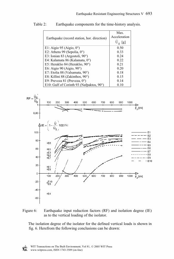
Table 2: Earthquake components for the time-history analysis.
Earthquake (record station, hor. direction) Max.
Acceleration
gU [g] E1: Aigio 95 (Aigio, 0°) 0.50 E2: Athens 99 (Sepolia, 0°) 0.33 E3: Ionian 83 (Argostoli, 90°) 0.24 E4: Kalamata 86 (Kalamata, 0°) 0.22 E5: Heraklio 84 (Heraklio, 90°) 0.21 E6: Aigio 90 (Aigio, 90°) 0.20 E7: Etolia 88 (Valsamata, 90°) 0.18 E8: Killini 88 (Zakinthos, 90°) 0.15 E9: Preveza 81 (Preveza, 0°) 0.14 E10: Gulf of Corinth 93 (Nafpaktos, 90°) 0.10
Figure 6: Earthquake input reduction factors (RF) and isolation degree (IE) as to the vertical loading of the isolator.
The isolation degree of the isolator for the defined vertical loads is shown in fig. 6. Herefrom the following conclusions can be drawn:
© 2005 WIT Press WIT Transactions on The Built Environment, Vol 81, www.witpress.com, ISSN 1743-3509 (on-line)
Earthquake Resistant Engineering Structures V 693
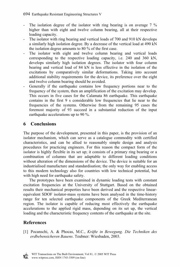
- The isolation degree of the isolator with ring bearing is on average 7 % higher than with eight and twelve column bearing, all at their respective loading capacity.
- The isolator with ring bearing and vertical loads of 700 and 910 kN develops a similarly high isolation degree. By a decrease of the vertical load at 490 kN the isolation degree amounts to 80 % of the first case.
- The isolator with eight and twelve column bearing and vertical loads corresponding to the respective loading capacity, i.e. 240 and 360 kN, develops similarly high isolation degrees. The isolator with four column bearing and vertical load of 84 kN is less effective in the isolation of the excitations by comparatively similar deformations. Taking into account additional stability requirements for the device, its preference over the eight and twelve column bearing should be avoided.
- Generally if the earthquake contains low frequency portions near to the frequency of the system, then an amplification of the excitation may develop. This occurs in five cases for the Calamata 86 earthquake. This earthquake contains in the first 9 s considerable low frequencies that lie near to the frequencies of the systems. Otherwise from the remaining 95 cases the foremost majority of 93 succeed in a substantial reduction of the input earthquake accelerations up to 90 %.
6 Conclusions
The purpose of the development, presented in this paper, is the provision of an isolator mechanism, which can serve as a catalogue commodity with certified characteristics, and can be allied to reasonably simple design and analysis procedures for practicing engineers. For this reason the compact form of the isolator is highly flexible in its set up; it consists of a primary ring bearing or a combination of columns that are adaptable to different loading conditions without alteration of the dimensions of the device. The device is suitable for an industrialised manufacture and standardisation; the only way for enabling access to this modern technology also for countries with low technical potential, but with high need for earthquake safety. The prototypes have been examined in dynamic loading tests with constant excitation frequencies at the University of Stuttgart. Based on the obtained results their mechanical properties have been derived and the respective linear-equivalent SDOF isolator-mass systems have been analysed in the time-history range for ten selected earthquake components of the Greek Mediterranean region. The isolator is capable of reducing most effectively the earthquake accelerations to the applied rigid mass, depending on its set up, the vertical loading and the characteristic frequency contents of the earthquake at the site.
References
[1] Pocanschi, A. & Phocas, M.C., Kräfte in Bewegung. Die Techniken des erdbebensicheren Bauens. Teubner: Wiesbaden, 2003.
© 2005 WIT Press WIT Transactions on The Built Environment, Vol 81, www.witpress.com, ISSN 1743-3509 (on-line)
694 Earthquake Resistant Engineering Structures V
[2] Uniform Building Code. Appendix Division III. Earthquake Regulations for Seismic-Isolated Structures. UBC, American Association of Building Officials: Whittier, CA, 1994.
[3] Kelly, J.M., Griffith, M.C. & Aiken, I.D., Comparison of earthquake simulator test results with the SEAOC tentative seismic isolation design requirements. Earthquake Spectra, 6(2), pp. 403-417, 1990.
[4] Phocas, M.C. & Pocanschi, A., Anpassungsfähige Erdbebenisolatoren für Gebiete mittlerer Seismizität. Forschungsbericht 25, ed. J. Knippers, Institut für Tragkonstruktionen und Konstruktives Entwerfen, Universität Stuttgart: Stuttgart, 2004.
[5] Newmark, N.M. & Rosenblueth, E., Fundamentals of Earthquake Engineering, Prentice-Hall: New York, 1971.
[6] Ambraseys, N., Smit, P., Berardi, R., Rinaldis, D., Cotton, F. & Berge-Thierry, C., Dissemination of European Strong-Motion Data. CD-ROM Collection, European Council, Environment and Climate Research Programme: Brussels, 2000.
© 2005 WIT Press WIT Transactions on The Built Environment, Vol 81, www.witpress.com, ISSN 1743-3509 (on-line)
Earthquake Resistant Engineering Structures V 695