Embed Size (px)
Citation preview

CLEI ELECTRONIC JOURNAL VOLUME 18 NUMBER 2 PAPER 3 AUGUST 2015
Towards an automatic model transformationmechanism from UML state machines to DEVS models
Ariel GonzalezUniversidad Nacional de Rıo Cuarto,
Rıo Cuarto, Argentina,[email protected]
and
Carlos LunaUniversidad de la Republica,
Montevideo, [email protected]
and
Roque Cuello, Marcela Perez, Marcela DanieleUniversidad Nacional de Rıo Cuarto,
Rıo Cuarto, Argentina,{cuello,perez,marcela}@dc.exa.unrc.edu.ar
Abstract
The development of complex event-driven systems requires studies and analysis prior todeployment with the goal of detecting unwanted behavior. UML is a language widelyused by the software engineering community for modeling these systems through statemachines, among other mechanisms. Currently, these models do not have appropriateexecution and simulation tools to analyze the real behavior of systems. Existing toolsdo not provide appropriate libraries (sampling from a probability distribution, plotting,etc.) both to build and to analyze models. Modeling and simulation for design and pro-totyping of systems are widely used techniques to predict, investigate and compare theperformance of systems. In particular, the Discrete Event System Specification (DEVS)formalism separates the modeling and simulation; there are several tools available onthe market that run and collect information from DEVS models. This paper proposesa model transformation mechanism from UML state machines to DEVS models in theModel-Driven Development (MDD) context, through the declarative QVT Relations lan-guage, in order to perform simulations using tools, such as PowerDEVS. A mechanismto validate the transformation is proposed. Moreover, examples of application to analyzethe behavior of an automatic banking machine and a control system of an elevator arepresented.
Keywords: Statecharts, DEVS, UML, MDA, QVT Relations.
1 Introduction
Model-Driven Development (MDD) [1, 2, 3] is a methodology that advocates the use of models as the primaryartifacts that drive the development of software, in order to increase productivity, quality and reduce costs[4, 5]. One of its main objectives is to organize abstraction levels and development methodologies, promotingthe use of models as the main artifacs to be constructed and maintained. A model consist of a set of elementsthat provide a synthetic and asbtract description of a system, specific or hypothetical. Thus, the developmentprocess becomes a refinement process and transformation between models, increasingly generating lower-level
1

CLEI ELECTRONIC JOURNAL VOLUME 18 NUMBER 2 PAPER 3 AUGUST 2015
abstraction models until, in the last step, specific platform code is generated. There is a growing interestin this field. In particular, the Model-Driven Architecture (MDA) [6] is the approach defined by the ObjectManagment Group (OMG) [7].
For the MDD, the Unified Modeling Language (UML) [7, 8] has become the standard for modeling thedifferent aspects of software systems, both in the academic environment and industrial developments. UMLfollows the Object Oriented paradigm and allows the description of both static and dyanimc aspects ofsoftware systems. More than a language, it is a set of languages, mostly graphic notations, supported bya significant number of proprietary and open source tools [9]. While UML is one of the preferred means ofcommunication between modeling experts, due to powerful grapical representation, this capacity is boundedin term of model execution, that is, the execution of a simulation.
In the simulation area, the Discrete Event System Specification (DEVS) [10] is a modular and hierarchicalformalism modeling and analyzing systems of various types; in particular, discrete event systems, systemsof differential equations (continuous systems), and hybrid systems (continuous and discrete) [11, 12]. DEVSprovides a theoretical basis for a system to run models using the DEVS simulation protocol [10, 13, 14]. TheDEVS models are hierarchical in nature and consist of atomic models and coupled models in order to builddesigns at different levels of asbtraction.
There is currently a major need of simulation tools for dynamic UML models to analyze the actualbehavior of complex systems. Moreover, it is recommended to apply modeling and simulation techniquesin early stages of software development, as these help to detect inconspicuous problems before deployment.UML is powerful in terms of its graphical representation, but weak regarding the execution of their dynamicmodels. In the software engineering community, state machines are one of the most used UML modelinglanguages [9, 15]. The present work aims to enhance the simulation of these using the DEVS formalism.Currently, DEVS is widely used by engineers within the academic world, who understand the modeling ofdiscrete event systems and are capable of translating system requirements to DEVS model code.
The main objective of this work is the proposal of a mechanism to execute and analyze UML statemachines through DEVS, a modeling and simulation formalism (M&S). A formal relationship is definedbetween elements of the state machines (State Charts - SCs), proposed by Harel [16], and the elementsof the DEVS formalism [10]. Furthermore, a DEVS representation (metamodel) is defined and a mappingfrom UML statecharts to DEVS models is presented, through transformation rules implemented in QVTRelations language (QVT-R) [17]. Finally, the implementation of a DEVS model is built and can then beimported by the PowerDEVS Simulation Tool [18] for the execution and analysis of the model. Even thoughthe development and analysis of simulations (on models obtained from the transformation) are not the focusof this work, we include examples of analysis of applications. Figure 1 shows the described process.
Even though the transformation of UML models for simulation purposes is not a new idea, and therealso exist other similar approaches that can be used as reference, this paper provides a sound process forachieving this objective, from both the conceptual perspective and the technical implementation perspective.This is the main contribution of this work.
Figure 1: Execution and analysis of UML state machines through DEVS
2

CLEI ELECTRONIC JOURNAL VOLUME 18 NUMBER 2 PAPER 3 AUGUST 2015
The rest of the paper is organized as follows. In Section 2 we describe the motivations that give rise tothe current proposal, along with other related works that are directly linked to this one. Section 3 introducesthe theoretical components that form the basis of the main issues, such as MDA, the SC’s, and the DEVSformalism. In Section 4 we present the formal transformation process of SC’s to DEVS models. Then, inSection 5 we define, first, the relations in QVT-R that implement the process, and then the C++ codegeneration to be imported by PowerDEVS. Section 6 describes a proposal to validate the transformation. InSection 7 includes two application examples: the analysis of the behavior of an automatic banking machineand a control system of an elevator. Finally, in Section 8 detailed conclusions and future work discussionsare presented.
The full development is available at https://www.dropbox.com/sh/4e0zorfyvgdmdg3/dnfWO_ija9.A preliminary version of this paper appeared in XL CLEI [19].
2 Motivation and Related Work
Mapping UML components to DEVS models (and vice versa) is not a new idea, nor an isolated initiative.There are many research projects that aim to integrate developments in modeling and simulation, generatingdifferent methodologies, processes and specific frameworks. However, our proposal differs from previousworks on issues that we discuss in this section.
There are different tools that support UML (UML Computer Aided Software Engineering - UML CASE)providing simulation capabilities, such as IBM Rational Rose [20, 21] and Poseidon [22]. These tools haveproprietary simulation engines which are not extensible and can not be tailored to meet specific requirements.For the current proposal a specific simulation engine is required to support simulation processes in detail(time event management, probability distributions, etc.), such as PowerDevs.
For the representation of DEVS models there are different approaches. One of such approaches is theStructure Entity Modeler Scalable with Complexity Measures (SESM/CM) [23] which is adequate for: de-veloping component-based hierarchical models, modeling behavioral aspects of atomic models, providingstructural specifications, and storing the models using XML. However, this approach is closer to the sim-ulation experts than domain experts and it needs further development to represent atomic models usingXML.
In [24] and [25] another metamodel is defined to represent DEVS systems through XML. In both cases,JavaML [26] is used to describe the behavior of an atomic model. This solution is suitable for transformingplatform specific models to platform independent models, but it does not provide a graphical solution formodeling such systems. One of the goals of our research project is to incorporate in the future a tool forviewing and editing models. Another tool that is available is ATOM3 [27] which is a good solution sinceit has a layer of metamodeling that allows describing domain specific modeling languages, and a layer thatsupports construction, modification and transformation of domain models.
In the field of modeling and simulation based on UML, several authors have approached the subject fromdifferent perspectives. Choi [28] uses UML sequence diagrams to define the behavior of a system. In [29]eight steps to build DEVS models using UML are introduced, but in this case many human decisions areneeded to transform the model.
In [30], Zinoviev presents a formal mapping from DEVS to UML. In this technique, input and outputports are mapped to UML events. Not continuous DEVS state variables are mapped to UML states andthose that are continuous are mapped to attributes of an UML state. The mapping presented is elegant, yettheir representation in UML does not tend to provide a unified representation for the modeling formalism.
Huang and Sarjoughian define in [31] a mapping for coupled models in UML-RT structure diagrams [32,33], but the use of UML profiles for planning, performance and time specification (OMG2005) is unnecessaryfor mapping DEVS to UML. They conclude that UML-RT is not suitable for a simulation environment, andargue that the software design and simulation are inherently different.
In [34] an informal mapping from DEVS to a STATEMATE statechart is introduced. Shulz indicates thatDEVS has greater expressive power than the statechart [35], and that any DEVS model can be representedby a StateMate activity diagram, together with an appropiate indentifier convention for events.
In the MDA context, Tolk and Muguira [36] show how complementary ideas and methods of High LevelArchitecture (HLA) and DEVS can be integrated into a well-defined M&S application domain, within theMDS framework. HLA has a distributed simulation architecture, independent of the computing platform. Itprovides an interface in which each simulation engine must conform to participate in a distributed simulationexercise. While it is widely used in the defense industry, its adoption in commercial industry has beenrestricted. The HLA interface specification does not include a network protocol for Run-Time Infrastructure(RTI). It is up to the developers of an RTI to create a specification. Due to this, interoperability between
3

CLEI ELECTRONIC JOURNAL VOLUME 18 NUMBER 2 PAPER 3 AUGUST 2015
RTI products and often, RTI versions, should not be assumed, therefore, this limits their use in commercialindustry.
Transformations between UML and DEVS models are presented in [37] and [38]. In [37], the authorstransform sequence diagrams to Finite and Deterministic DEVS to verify by means of space state explorationand to validate a set of traces by means of a simulation. The extension of the modeling language basedon DEVS (E-DEVSML) proposed in [38] can help modelers to simulate systematically the systems. Also,an approach to make UML diagrams executable through an automated model transformation process usingE-DEVSM is described. However, it does not specify the types of UML diagrams that are transformedand presents a proposal based on scarce bibliography. Neither [37] or [38] analyze the validation of thetransformation or discuss possible mechanisms.
In [39], the authors present a new extension to the DEVS formalism, called Rational Time-AdvanceDEVS (RTA-DEVS) which can be fomally checked with standard model-checking algorithms and tools.This is done by means of a procedure that creates Timed Automata models that are behaviorally equivalentto the original RTA-DEVS models via a transformation models. This paper also presents a validationmechanism of transformation using the technique known as Correctness-by-Construction.
In [40], Mittal and Risco-Martin present eUDEVS (Executable UML with DEVS Theory of Modelingand Simulation) where the authors analyze not only the specification of the structure and the behavior ofDEVS models in UML, but also a method for modeling general purpose DEVS models, which supports thespecification, analysis, design, verification and validation of a wide variety of systems based on DEVS. In[40] an M&S methodology consisting of three steps is proposed. First, the static structure of the UML statemachine is synthesized and its corresponding representation in State Chart XML (SCXML) [41] is gener-ated. Second, the SCXML file is converted to a DEVS finite and deterministic state machine model (FinteDeterministic DEVS - FD-DEVS), defined by Mittal in [42], which specifies its behavior. At this stage themodel is totally platform independent. Finally, from the XML FD-DEVS, a simulation model is generatedusing a series of XML-based transformations, to be executed later by the DEVSJAVA [43] simulation engine.The proposed method is interesting and ambitious, but the employment of XSL transformations (eXtensibleStylesheet Language Transformations - XSLT) makes it unclear. Additionally, the work is based on a rep-resentation of the SCXML state machine defined by the World Wide Web Consortium (W3C), which doesnot consider all elements of UML state machines. SCXML is a general-purpose event-based state machinelanguage that can be used in many ways and is currently a working draft specification. Also, it provides ageneric state-machine based execution environment based on Harel state tables, Commons SCXML. Com-mons SCXML is an implementation that creates and maintains a Java SCXML engine capable of executinga state machine defined using a SCXML document, however, it does not provide libraries for analysis of themodels.
This work differs from the above, and especially from [40], in the following aspects:
• A proposal in the context of the MDA is made;
• A formal mapping between the SC’s, defined by Harel, and DEVS models is performed;
• A QVT-R transformation, model-to-model (M2M), implementing the mapping from UML state ma-chines to DEVS models is defined. It employes a declarative language standardized by the OMGinstead of using imperative languages or XML transformation tools. The instrumentation of transfor-mation rules through XML definitions leads, in general, to unclear and difficult developments. XSLtransformations are very different from a programming language since they are based on the use oftemplates which often are difficult to maintain when they become large. In contrast, transformationlanguages such as QVT and ATL have similar styles to programming languages. In particular, QVT-Rfollows the style of the logical-relational paradigm. This feature allows us to define transformations asdeclarative, modular, easier to extend and modify specifications.
• A C++ code of DEVS models is generated to be imported by the PowerDEVS (open source) simulationtool.
• Mechanisms to validate transformations are discussed, while this is not done in [40].
• Our proposal focuses on discrete dynamical systems, where time constraints occur in many places anddrive the evolution of these systems. For example, elevator systems and assembly machines.
Even though the transformation of UML models for simulation purposes is not a new idea, and there alsoexist other similar approaches that can be used as reference, we propose a model transformation mechanismfrom UML SC’s to DEVS models in the MDD context, through the declarative QVT-R language, in order
4

CLEI ELECTRONIC JOURNAL VOLUME 18 NUMBER 2 PAPER 3 AUGUST 2015
to perform simulations using tools, such as PowerDEVS. Further research will develop a unified tool thatcontains a specific modeling environment that allows the representation of systems with UML elementsconsidered in this work, along with the transformation to DEVS models. We also propose to integratePowerDEVS for the implementation and analysis of the models.
3 Preliminary Notions
3.1 Model-Driven Architecture (MDA)
MDA is an OMG initiative that proposes a set of standards which specify interoperable technologies toimplement the principles of MDD, incorporating automated transformations. MDA defines a process ofsoftware construction based on the production and processing of models. The principles on which MDAis based are: abstraction, automation and standardization. The MDA central process consist in modeltransformation. The main underlying idea is to use models, so that the properties and characteristics of thesystems remain contained in an abstract model, independent of the changes in technology. MDA provides aset of guidelines or standards expressed as models and establishes four levels of abstraction: ComputationIndependent Model (CIM), Platform Independent Model (PIM), Platform Specific Model (PSM), and thefinal application. The CIM models describe the environment in which the system is used, without directreference to its implementation. The PIM models describe the functionality and structure of an informationsystem without considering technological details of the platform on which the system is implemented. ThePSM models describe the specific platform where the system is executed. MDA proposes the followingdevelopment process: from requirements we get a PIM, then this model is transformed with the help of oneor more tools in PSM, and finally each PSM is transformed into code. Therefore, MDA incorporates the ideaof models transformation (CIM to PIM, PIM to PSM, PSM to code), making use of tools for the automationof these activities. Figure 2 shows the process and the roles defined by MDA.
The principle of abstraction used by MDA focuses its attention on the problem domain rather than onthe technology. Different models aim at the definition of a semantic that separates relevant aspects of theproblem from those related to the technology. Regarding automation, MDA favors the emergence of newCASE tools with specific functionalities for the exchange of models, consistency verification, processing andhandling of meta models, among others.
Figure 2: MDA processes and roles
5

CLEI ELECTRONIC JOURNAL VOLUME 18 NUMBER 2 PAPER 3 AUGUST 2015
Mapping and Model Transformation
A set of mappings between models from different abstraction levels are established in Figure 2. Thesemappings can also be defined between models belonging to the same level. Below are some of the possibletransformations:
• Mapping PIM to PIM. It is applied in order to optimize them for the duration of the developmentprocess. This mapping does not require any information on the implementation platform.
• Mapping PIM to PSM. It is applied in cases where it has a PIM resulting from a series of refinementsof PIM to PIM. This mapping will be implemented in a dependent architecture of a specific platform.
• Mapping from PSM to PSM. It is applied during the encoding and component development. Thismapping is linked to the refinement of PSM own models.
• Mapping from PSM to PIM. This transformation may be required to generate abstract models fromexisting implementations. It can be used in order to extract into generic models, desirable propertiesof a system.
• Mapping from PSM to code. Enables the generation of specific source code to a particular platformfrom a PSM.
The languages most commonly used to describe model-to-model transformations are QVT and ATL(Atlas Transformation Language) [44]. In the present work we opted for QVT-R (QVT-Relations) for itssimplicity and clarity to define relationships between elements of the source and target metamodels.
Query/View/Transformation (QVT) The OMG defined the QVT standard [17] to work with softwaremodels. QVT consists of three parts: query, view and transformation. In particular, a transformationmetamodel describes relationships between a source metamodel S, and a target metamodel T, specified inMOF [45]. The QVT specification 1.1 has a declarative/imperative hybrid nature. In this work the Relationsdeclarative language is employed. The tool used for the definition of the transformations is called MediniQVT[46]. This tool implements the OMG QVT-R specification into a powerful engine QVT. Its interface is basedon Eclipse, and use Eclipse Modeling Framework (EMF) [47] for representing models. MediniQVT requiresthat metamodels (and models) be written in a simplified version of the MOF standard, called Ecore [48],which is defined in the EMF. An Ecore metamodel is represented in XML; however has an EMF Ecoremodels graphic editor which facilitates the creation thereof.
Ecore and Ecplispe Modeling Framework Characteristics The metamodels and EMF models usedare represented by XML documents; EMF has a graphical editor which facilitates the creation of Ecoremodels. There are tools that automatically treat these metamodels and models, including the Eclipse plug-in to transform these models, with the definition of QVT transformations. The features and elements of themodeling language Ecore are: the unifying element (root) is the package EPackage, which physically containsits elements (containment specification) and, in turn, these may be contained in other packages. There isa factory (EFactory) per package that allows the creation of model elements. Constructs that describea set of elements (instances) are classifiers (EClassifiers): EClass and eDataType. Ecore specifies thecharacteristics of the classes (EClass), their structural characteristics (EStructuralFeatures), attributes(EAttributes), operations and relationships (inheritance, reference (EReference)). The EClass have asuperclass and is composed of structural features (EStructuralFeatures: EReference and EAttribute).Both EAttributes and EReferences may be provided with multiplicity. The EDataTypes model basicor indivisible data model types, and the EReferences may be contained or be references (pointers). TheOperations model the operations of the interface (although implementation is not provided for them). Allelements inherit from ENamedElement (nameless) and EModelElement (model element). Moreover, everyelement of the model can have associated annotations (EAnnotation): name / value pairs for additionalspecifications; eg, OCL constraints or documentation strings.
3.2 State Machines
A SC is a visual representation of a finite state automata with hierarchy of states. These machines wereintroduced by Harel [16] and incorporated into the various versions of UML with some variations. The mainfeature of the SCs is that their states can be refined, thus defining a hierarchy of states. The decompositionof a state can be sequential or parallel, in the first, a state decomposes into an automaton, while in thesecond it breaks down into two or more automata running concurrently. Although this hierarchy is allowed,
6

CLEI ELECTRONIC JOURNAL VOLUME 18 NUMBER 2 PAPER 3 AUGUST 2015
a SC with composite states has its equivalent using only simple statements. In this paper, we will rely on thedefinition and application of SCs containing only simple statements. There are many algorithms and toolsthat convert a SC with composite states to an equivalent SC with simple states [16, 49, 50]. Transitions aredirected. A transition (t) is formed by its name, origin state, the event that “triggers” it (e), the triggercondition (c), the actions to be executed ([alpha]) and destination state. The graphical notation used ist : e, c/α.
3.3 M&S and DEVS
A model is a representation of the construction and working of some system of interest. A model is similarto but simpler than the system it represents. One purpose of a model is to enable the analyst to predictthe effect of changes to the system. On the one hand, a model should be a close approximation to the realsystem and incorporate most of its salient features. On the other hand, it should not be so complex that itis impossible to understand and experiment with it. Generally, a model intended for a simulation study isa mathematical model developed with the help of simulation software. Mathematical model classificationsinclude deterministic (input and output variables are fixed values) or stochastic (at least one of the input oroutput variables is probabilistic); static (time is not taken into account) or dynamic (time-varying interactionsamong variables are taken into account). Typically, simulation models are stochastic and dynamic.
Simulation is a descriptive tool, allowing us to experiment with a model instead of the real system. Thepropose of simulating, generally falls into one of three categories as follows:
• Comparison. A comparison of simulation runs can be used to assess the effect of changing a decisionvariable. The results of the different runs can then be evaluated in terms of the objetives.
• Prediction. A simulation may be used for predictive proposes to determine the state of the system atsome future point in time, subject to assumptions about how it behaves now and how it will continueto behave.
• Investigation. Some simulations are developed to provide an insight into the behavior of the system,rather than to perform detailed experimentation. It is of interest to see how the simulation behavesand reacts to normal and abnormal stimuli.
Simulation is used before an existing system is altered or a new system built, to reduce the chances offailure to meet specifications, to eliminate unforeseen bottlenecks, to prevent under or over-utilization ofresources, and to optimize system performance.
During the last decades, the rapid evolution of technology has produced a proliferation of new dynami-cal systems of great complexity. Examples include computer networks, automated production systems, airtraffic control, and general systems of command, control, communications and information. All the activ-ities in these systems are due to the occurrence of asynchronous discrete events, some controlled (such aspressing a key) and some not (like spontaneous equipment failure). This feature is what leads to define theterm: Discrete Event Systems (Discrete-Event Systems - DES) [51]. Among the most popular formalismsfor representation of DES are Petri Nets, the SC, Grafcet, Event Graphs, and many generalizations andparticularizations of them.
With the motivation of problem-oriented modeling and simulation of DES, in the decade of the ’70Bernard Zeigler proposed a theoretical framework and a methodology for M&S systems. It is here thatarises DEVS [10], a formalism for modeling with a solid semantic, based on a theoretical system basis. Thisformalism, sometimes pointed as universal, allows to describe dynamic discrete event systems. Its universalitymeans that any formalism for these systems can be adjusted to DEVS. Because of its great adaptation formodeling complex systems and the simplicity and efficiency of the implementation of simulations, DEVS iscurrently one of the most used tools in modeling and simulation by mean of discrete events. In Section 4.2the details of the formalism are presented.
4 From State Machines to DEVS Models
The main objective of this work is to provide a mechanism that achieves the execution of UML SCs, througha process that transform them to DEVS atomic models, to later be able of carrying simulations on them.To build this process of transformation is necessary to make a review of the elements of each formalisms.Subsequently, a mapping between them through a set of rules that indicate how information from one domaintranslates to another is defined. These rules are especially needed because although the domain elements ofa SC has similar aspects from the DEVS ones, the specification of DEVS elements is more stringent.
7
CLEI ELECTRONIC JOURNAL VOLUME 18 NUMBER 2 PAPER 3 AUGUST 2015
4.1 Formal Definition of a SC
The UML SCs are based on the SCs defined by Harel. They are composed by a set of states, transitions andevents. Formally, following [52], a SC is defined as a tuple ⟨S,Σ, T, A⟩, where:
• S : is a finite (non-empty) set of states.
• Σ : is a finite set of events.
• T is a finite set of transitions represented by the tuple t = (t′, so, e, c, a, sd), where:
– t′ is the transition name;
– so ∈ S is the origin state;
– e ∈ Σ is the trigger event;
– c is a trigger condition;
– a ∈ A A is an action to be executed when the transition occurs;
– sd ∈ S is the destination state.
• (A ⊆ Σ): is a set of actions, where τ ∈ A represents the “null action” or “skip”.
For convenience, a life time (or residence time) can be associated to a state. These are used to describe anew behavior, that defines for how long the system can remain in a state. When time has elapsed, a specialtransition must be triggered. This behavior could also be implemented by associating a time event to atransition, which fires when the origin state reaches that time. On one hand, the association of time to eachstate is formalized, and secondly, a special event γ ∈ Σ called time event to be used in transitions that aretriggered upon reaching the time in his origin state. We refer to these transitions as time transitions. Onlyone time transition must be defined by each state, and the life time must be not equal to ∞.
The SC formal definition is extended with the following components: ⟨S,Σ, T, A,Π⟩, where:
• Π : S × ℜ+0,∞ is a set of pairs that associates with each state a value in ℜ+
0,∞, that represents the lifetime.
• γ ∈ Σ is the time event.
• Si Π(s) = ∞ then there must be a unique time transition (t′, s, γ, true, a, sd) with origin s.
Figure 6 shows an example of a SC. Note that the transitions are triggered when the life time runs outin their origin state (time transition) are drawn simply by associating the life time of their origin state andaction output; the event (event time τ) and condition (true) are not drawn.
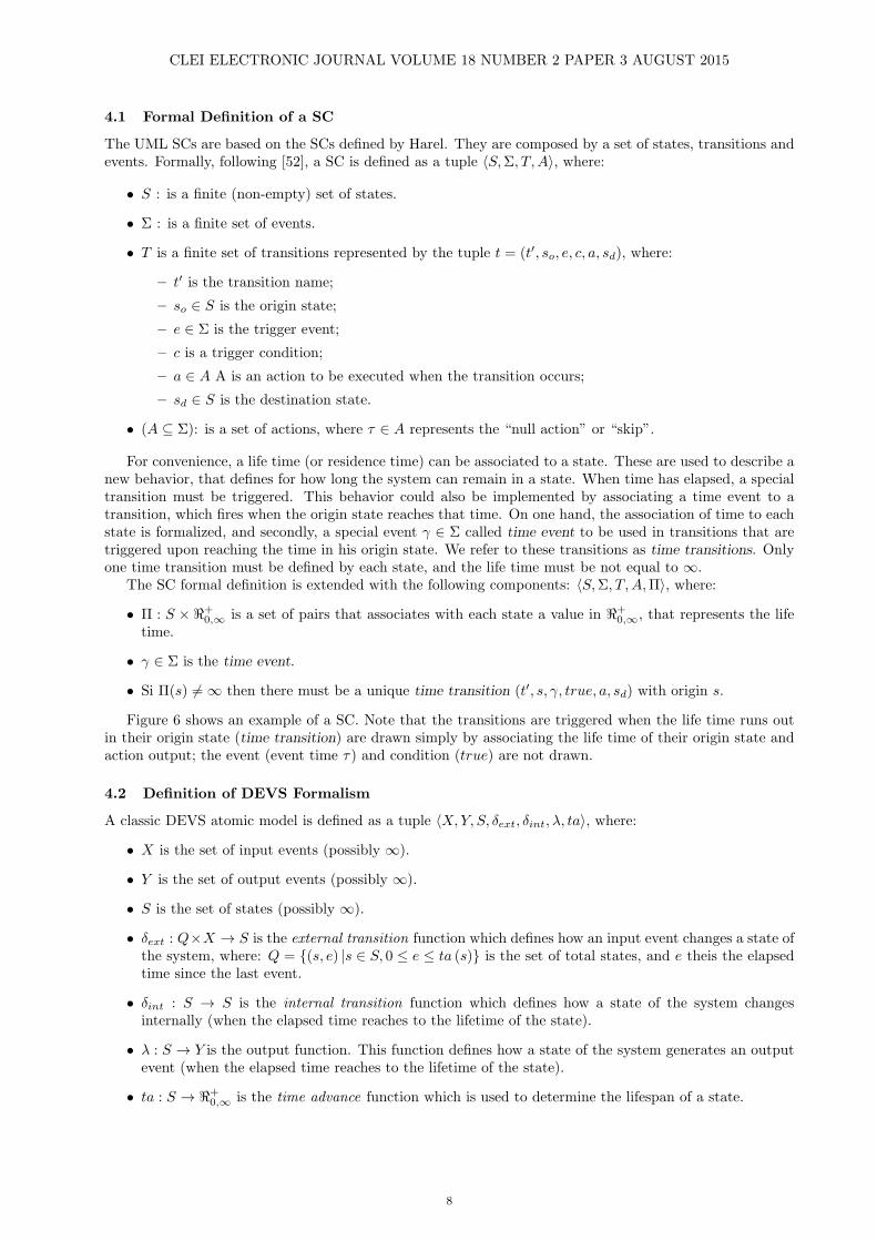
4.2 Definition of DEVS Formalism
A classic DEVS atomic model is defined as a tuple ⟨X,Y, S, δext, δint, λ, ta⟩, where:
• X is the set of input events (possibly ∞).
• Y is the set of output events (possibly ∞).
• S is the set of states (possibly ∞).
• δext : Q×X → S is the external transition function which defines how an input event changes a state ofthe system, where: Q = {(s, e) |s ∈ S, 0 ≤ e ≤ ta (s)} is the set of total states, and e theis the elapsedtime since the last event.
• δint : S → S is the internal transition function which defines how a state of the system changesinternally (when the elapsed time reaches to the lifetime of the state).
• λ : S → Y is the output function. This function defines how a state of the system generates an outputevent (when the elapsed time reaches to the lifetime of the state).
• ta : S → ℜ+0,∞ is the time advance function which is used to determine the lifespan of a state.
8
CLEI ELECTRONIC JOURNAL VOLUME 18 NUMBER 2 PAPER 3 AUGUST 2015
A system that is in a state s ∈ S will remain in it for a ta(s) period of time, unless an input event withvalue x ∈ X occurs, after a time e lower or equal to ta(s) elapses. In this case, the system will experiencean external transition to the state s′ = δext (s, e, x). However, if the elapsed time e is equal to ta(s) withoutexternal events have taken place, an internal event will occur leading to an internal transition. This willproduce an output event with value y = λ (s) and a transition to a new state s′′ = δint (s). In both cases,the system will remain in the new state, by the time ta determined or until an external event occurs again.
Note that in the definition of DEVS filed, the time advance function supports associating a time 0 or∞ to a state s ∈ S. In the first case, the system may remain 0 units of time in s. Therefore, when s isreached, an internal transition happen immediately generating an output event and a state change. Such astate is called transitory state. Moreover, when the system reaches s whose associated time is ∞, no internaltransitions will exist and will remain forever in this state unless an external event occurs. Such a state iscalled passive.
4.3 Element Mapping
Model transformations are defined as programs that take a model (or more than one) as input and returnsanother model (or more than one) as output.Consist of a set of rules describing how one or more sourcemodel elements are transformed into one or more elements of the target model. Below is formally definedthe set of rules that describe how the elements of the source model are transformed into elements of thetarget model by extracting the necessary information from a SC to build a DEVS atomic model.
Given ME = ⟨Suml,Σ, T, A,Π⟩ a SC, and MA = ⟨X,Y, Sdevs, δext, δint, λ, ta⟩ a DEVS atomic model, thetransformation rules are defined as follows:
1. Rule 1: states from Suml and their life time are transformed DEVS states, where: Sdevs = {(s, σ)|s ∈Suml,Π(s) = σ}. On the other hand, the ta function is defined as: ta((s, σ)) = σ.
2. Rule 2: an event e ∈ Σ is transformed into a DEVS input event with the same name; X = Σ− γ.
3. Rule 3: an action a ∈ A is transformed into a DEVS output event with the same name; Y = A.
4. Rule 4: to define the transitions mapping is necessary to distinguish particular cases, as in ME all theinformation is contained in the tuple that defines the transition, while on a DEVS model it is specifiedin various elements of the atomic model. This classification is to distinguish transitions according totheir trigger (event time and the rest), and according to a certain action or null action attached to it.
• Rule 4.1: a transition t ∈ T that is triggered by the occurrence of a time event (γ), is transformedinto an internal transition in MA.
Given t = (t′, so, γ, true, a, sd) ∈ T :
δint((so, σ)) = (sd,Π(sd)), and λ((so, σ)) = a.
• Rule 4.2: a transition t ∈ T that is triggered by the occurrence of an event e = γ and containsthe null action τ , it is transformed into an external transition in MA.
Given t = (t′, so, e, c, τ, sd) ∈ T , where e = γ:if c then δext(((so, σ), te), e) = (sd,Π(sd)) else δext(((so, σ), te), e) = (so, σ − te)).
• Rule 4.3: a transition t ∈ T that is triggered by the occurrence of an event e = γ and contains anon-null action a = τ , produce the following elements in MA.
Given t = (t′, so, e, c, a, sd) ∈ T , where e = γ, and a = τ :
(a) it is defined an intermediate state so − sd with life time 0, in order to produce as output ofthe model MA, the action a: (so − sd, 0) ∈ Sdevs;
(b) an external transition from so to so − sd: δext(((so, σ), te), e) = (so − sd, 0);
(c) an internal transition from so − sd to sd: δint(so − sd, σ) = (sd,Π(sd));
(d) an element from the output function that maps so − sd to the output event (action) a:λ(so − sd) = a.
5 Implementing the Transformation with QVT and Exporting to PowerDEVS
In this section an implementation of the transformation rules from UML statecharts to DEVS atomic modelsbased on the QVT-R language is proposed. Subsequently, the exporting method of the resulting model isdescribed, so that it can be interpreted by PowerDEVS.
9

CLEI ELECTRONIC JOURNAL VOLUME 18 NUMBER 2 PAPER 3 AUGUST 2015
A set of QVT relations that implement the rules detailed in Section 4.3 is defined. We make use of theUML 2.4.1 metamodel described in the official website of the OMG [8]. In function of this specification, theUML elements that are used to support the formalism of the SCs defined in 4.1 are described. Later, theDEVS formalism metamodel presented in Section 4.2, is defined in Ecore format.
An execution of rules in QVT receives a model (or instance) of a UML SC satisfies the UML metamodelin Ecore [47], and builds a DEVS atomic model that satisfies the respective metamodel in Ecore format.
Table 1 reflects briefly which UML elements are used to model the SCs defined in Section 4.1.
Table 1: Mapping between SC elements (formal definition) and UML 2.4.1 elements
Definition Description Ecore (EClass)ME state machines StateMachineS state StateΣ event SignalEventA action FunctionBehaviorT transition TransitionΠ life time Constraint
DEVS Metamodel
The DEVS metamodel definition is based on the specification described in Section 4.2 and is built withthe MediniQVT tool. Note that each element of the tuple that defines the DEVS models is defined by ametaclass. Figure 3 shows graphically that metamodel. Briefly, Table 2 describes the relationship betweenthe elements from the formal definition of an DEVS atomic model and elements of the Ecore metamodel.
Figure 3: DEVS metamodel
10

CLEI ELECTRONIC JOURNAL VOLUME 18 NUMBER 2 PAPER 3 AUGUST 2015
Table 2: Mapping between DEVS atomic model elements (formal definition) and its representation in Ecore
Definition Description Ecore (EClass)MA atomic model AtomicModelS state StateX input event InputEventY output event OutputEventδint internal transition InternalTransitionδext external transition ExternalTransitionλ output function OutputFunctionta time advance lifeTime(Double)
5.1 Transformation Rules in QTV-R
The definition of relationships (rules) in QVT-R implement the rules specified in 4.3. These transformationrules are written declaratively and describe consistent relationships between the set of elements of eachmodel. This consistency can be verified by running the transformation in checkonly mode (read-only), witha satisfactory result if both models are consistent according to the relations. Similarly, it can be executedin enforce mode to modify or build one of the models, so that both satisfy the relations at the end of theexecution. In this paper, QVT relationships are built by checking the UML model, and enforcing the DEVSone, thus the elements of first maps to elements of the second.
For space reasons, the relevant parts of the code relationships are shown. In particular, only the construc-tion of states, input events and partly the construction of internal and external transitions from the DEVSatomic model are shown. In https://www.dropbox.com/sh/4e0zorfyvgdmdg3/dnfWO_ija9 it is possibleto download the full definition of the rules. Note that a rule defined in Section 4.3 may be implemented bymore than one relationship in QVT-R.
The relationship state2state builds the DEVS model states according to the following mapping: thename of the DEVS state corresponds to the name that has in the UML model and its lifetime specified onthe UML (Constraint) time constraint.
top relation state2state {
nameS: String;
checkonly domain smUml s_source :uml::State {
container = regionsource :uml::Region{
stateMachine = sm :uml::StateMachine{} },
stateInvariant = s_stateInvariant :uml::Constraint{
specification = spec :uml::ValueSpecification{} },
name = nameS
};
enforce domain smDevs s_target :devs::State {
atomicModel = am :devs::AtomicModel{},
lifeTime = spec.oclAsType(uml::LiteralDouble).value,
name = nameS
};
when {
statemachine2atomicmodel(sm,am);
}
}
The UML events SignalEvent are mapped to InputEvent elements of the DEVS metamodel. This isdefined by the relationship signalEvent2inputEvent.
top relation signalEvent2inputEvent {
nameT : String;
checkonly domain smUml s_source :uml::SignalEvent {
name = nameT
};
enforce domain smDevs s_target :devs::InputEvent {
name = nameT
};
}
11

CLEI ELECTRONIC JOURNAL VOLUME 18 NUMBER 2 PAPER 3 AUGUST 2015
A UML transition that is triggered by the ocurrence of an external event and contains an action attachedto it, creates various elements of the resulting DEVS atomic model, according to the last rule defined inSection 4.3.
-- Source Transition.
top relation transition2mediatorState {
nameT : String;
checkonly domain smUml s_source :uml::Transition {
container = regionsource :uml::Region{
stateMachine = sm :uml::StateMachine{} },
source = ss_uml :uml::State{},
target = st_uml :uml::State{},
trigger = t_uml :uml::Trigger{
event = se_uml :uml::SignalEvent{} },
effect = a_uml :uml::Activity{
classifierBehavior = fb_uml :uml::FunctionBehavior{} },
name = nameT
};
-- Middle Status
enforce domain smDevs s_target_MS :devs::State {
atomicModel = am :devs::AtomicModel{},
lifeTime = 0.0,
name = ss_uml.name + ’-’ + st_uml.name
};
-- External transition
enforce domain smDevs s_target_ET :devs::
ExternalTransition {
atomicModel = am :devs::AtomicModel{},
source = ss_devs :devs::State{},
target = s_target_MS,
inputEvent = ie_devs :devs::InputEvent{},
name = ss_uml.name + ’to’ + s_target_MS.name +’(?’ + t_uml.name+’)’
};
-- Internal Transition
enforce domain smDevs s_target_ITTarget :devs::
InternalTransition {
atomicModel = am :devs::AtomicModel{},
source = s_target_MS,
target = st_devs :devs::State{},
name = s_target_MS.name + ’to’ + st_uml.name
};
-- Output Function
enforce domain smDevs s_target_OF :devs::OutputFunction {
atomicModel = am :devs::AtomicModel{},
state = s_target_MS,
outputEvent = oe_devs :devs::OutputEvent{},
name = s_target_MS.name + ’(!’ + fb_uml.name + ’)’
};
-- Preconditions
when {
state2state(ss_uml,ss_devs);
state2state(st_uml,st_devs);
signalEvent2inputEvent(se_uml, ie_devs);
function2outputEvent(fb_uml,oe_devs);
isUmlExternalTransition(s_source);
12

CLEI ELECTRONIC JOURNAL VOLUME 18 NUMBER 2 PAPER 3 AUGUST 2015
statemachine2atomicmodel(sm,am);
}
}
5.2 Exporting to PowerDEVS
The DEVS model resulting from the transformation can be exported to various tools to perform simulations;among others, PowerDevs, DEVSJAVA [43], DEVS-C++ [53], DEVSim++ [54], CD++ [55], and JDEVS[56]. These software tools provide different features, which include graphical interfaces and advanced simu-lation functionalities for general purpose and domain-specific DEVS models. In this paper we have chosenPowerDEVS, being an open source tool and easy to use to implement these models; moreover, it has versionsfor both Windows and Linux and is widely used in academia for teaching M&S.
PowerDEVS is implemented in C++ (with QT graphics libraries) and DEVS models must also be definedin C++. It consists of several separate programs:
• Model Editor : contains the graphical interface that allows, among other high-level definitions, thehierarchical construction of the structure of DEVS (files .pdm) models, which have a special syntax.
• Atomic Editor : allows to define in C ++ (.h and .cpp files) the behavior of the DEVS atomic models,i.e. transition functions, the output function, lifetime, and other elements of these models.
• Preprocessor : translates files from the Model Editor in structures with information necessary to buildthe simulation code, and links files created with the Atomic Editor compiling a stand-alone executablefile.
• Simulation Interface: runs the stand-alone executables, allowing to vary the parameters of the simu-lation.
• An instance of a Scilab execution where the simulation parameters are read and the results can beexported.
The export of a DEVS atomic model in Ecore produce, first, a file (.pdm) that defines the structure ofthe model and can be opened by the Model Editor, and secondly, the files that define the behavior (.h and.cpp) so that they can be interpreted by the Atomic Model. The algorithm that generates the code (XEP:XML Ecore to PowerDEVS ) was implemented by the authors of the current work and is based on the SaxonXSLT library and the XQuery Processor [57], which is a collection of tools for processing XML documents.
The export process described is shown in Figure 4. In Section 7 two examples of application can beobserved.
Figure 4: Exporting Ecore DEVS atomic models to PowerDEVS
6 Validation of the Transformation
To validate the application of existing theories and tools about the DEVS models, we need to constructDEVS models from UML SCs models with equivalent behaviors.
In previous sections, we define the transformation by a systematic method and then develop their imple-mentation, but these mechanisms need to be validated in order to increase the credibility of the results.
13

CLEI ELECTRONIC JOURNAL VOLUME 18 NUMBER 2 PAPER 3 AUGUST 2015
The validation of a model transformation typically includes properties which involve the syntactic cor-rection of the transformation with respect to its specification language and syntactic correction of modelsproduced by the transformation [58, 59], but few proposals focus on the semantic consistency of the trans-formation, i.e. the preservation of the correction of the target model in relation to the origin model. In orderto do this we can apply both empirical and theoretical (formal) validation methods.
6.1 Empirical Validation
In the context of MDD, software development is based on the refinement of models until they become codes.An example of this is the theory of refinement of Dijkstra [60], widely applied in the area of formal methods.However, it is difficult to adapt the theory to the validation of the model transformation. [61] describesan agile formal proposal for semantic validation specifying the structures of refinement with OCL whichare equivalent to those employed in the formal languages. This proposal has the support of the softwareengineering community, due to the fact that it uses known languages. Generally, refinement is verified bydemonstrating that the actual system simulates the abstract system.
This paper does not specifically propose a refinement, it aims to obtain an equivalent or more generalmodel in the context of simulation systems, in order to take advantage of existing analysis tools. The modelvalidation mechanisms in the field of M&S are clearly suited to our proposal. The model validation methodstry to show that the models actually represent the actual system which is one of the most important anddifficult tasks faced by a modeler. Therefore, assuming that the validation of the state machine was made,in our proposal, empirical validation of the transformation is limited to the validation of the DEVS model,that is, to determine that the new model resulting from the transformation also models the real system.This is represented in Figure 5.
Real System
UML SC model DEVS modelTransformation
Validation Validation
Figure 5: Empirical validation of the transformation
The modeler should work closely with end users during periods of model development and validation inorder to increase the credibility of the model. We can find various model validation strategies in the currentliterature [62] [63] but the main goals of the validation process are common to all:
• To produce a model that represents a real system behavior, real enough to use it instead of the originalsystem in experimentation and analysis.
• To raise the credibility of the model to an acceptable level so that it is used by those responsible formaking decisions.
In the validation process it is important:
• To examine at the model outputs and determine its acceptability, under a variety of configurations ofthe input parameters. To make this model present a wide variety of statistical results, which shouldbe examined carefully.
• To make the model print the input parameters while analyzing the simulation and verify that theirvalues have not been changed.
• To document the model as much as possible.
• If the operational model is animated, to verify by means of the observation of the simulation that themodel imitates the real system.
14

CLEI ELECTRONIC JOURNAL VOLUME 18 NUMBER 2 PAPER 3 AUGUST 2015
• To monitor the simulation: tracking specific entities, monitoring of the component values, etc.
• To review the acceptability of the model outputs in detail.
• To calculate certain measures of long-term performance analytically, if possible, and then comparethese results with the values that the system provides. his is very important in validating models.
• To use both the real system and the model, the same sets of input data to compare the outputs.
6.2 Proposal for Theoretical Validation
Recent studies describe validation and verification techniques of model transformations. In [64], the idea isto convert a model transformation system into a relational logic specification. The Alloy model analyzeris used to check if any invalid target model is created by the transformation. Other strategies achieve thecorrection of the transformation by means of the correct-by-construction using transformation patterns [65]or using ontologies [66].
In the context of state transition systems there are simulation and/or bisimulation techniques [67, 39]that could be applied in this work. These techniques attempt to formally prove that a state transition systemincludes the behavior of another, and vice versa. In our proposal we must demonstrate, in particular, thatthe behavior of the resulting DEVS model preserves the behavior of the SC, in other words, that the DEVSmodels behave like the SCs.
A simulation is a binary relation between two systems associated state transition systems where thebehavior of one includes the other. A bisimulation is a binary relation between two systems of state transition,which combines systems that behave in the same way. This means, a system simulates another system andvicerversa.
In this work the SCs and DEVS models are state transition systems including time constraints (TLTS).Considering [67], a timed simulation is a binary relation R over a set of states of a TLTS defined as follows:
R is a timed simulation iff ∀(p, q) ∈ R, if pα−→ p′ then ∃q′, q α−→ q′ ∧ (p′, q′) ∈ R
Where α is an external event or permanence time associated with a state.Two TLTSs are said to be bisimilar iff there exists a bisimulation between their state spaces.In a TLTS the eventual transition relation defines a transition from state s to state t that may contain
one or more direct transitions labeled. The eventual transition relation (=⇒) between s and t on α (sα
=⇒ t)is defined as follows:
sα
=⇒ t iff there is an eventual transition relation from s to t (with α = d(delay) or α = e(event)),which is composed of one or more direct transitions. This represents the following sequence of transitions:
sα−→ s′(
0−→)∗t, proved that the only transition output s′ is an even transition time with delay zero, where ∗
defines zero or more occurrences of transition0−→.
Weak timed bisimulation
A weak timed simulation [67] is a binary relation R over a set of states of a TLTS. If we have states s1, s′1, s2
and s′2, R is a weak timed simulation s1Rs2 iff: if s1α−→ s′1, then there is a transition s2
α=⇒ s′2.
We choose the weak bisimulation relation to validate the transformation from SCs to DEVS, as thisrelation allows two models to be in simulation relation even with if one of them has some different transitionsfrom the other, provided that these extra transitions are time transition with delay zero.
Preservation of semantics
Given ME = ⟨Suml,Σ, T, A,Π⟩ a UML SC, and MA = ⟨X,Y, Sdevs, δext, δint, λ, ta⟩ the DEVS atomic modelresulting of the transformation. If we define R as: siR(si, σ) where si ∈ Suml and (si, σ) ∈ Sdevs accordingto rule 1 defined in section 4.3, then R is a weak timed bisimulation, which means that MA simulates ME.
Demonstration and a more detailed analysis of the proposal will be considered in the future.
7 Aplication Examples
Two examples are presented in this paper. The first case study shows the simplified operation of an AutomaticBanking Machine (ABM). The purpose of this one is to give a general view of the mapping from a UML SC toa DEVS model, showing formal and graphical representations. The second example models the behavior ofa control system of an elevator, in order to estimate certain performance variables, such as the average time
15

CLEI ELECTRONIC JOURNAL VOLUME 18 NUMBER 2 PAPER 3 AUGUST 2015
Figure 6: UML SC of an automatic banking machine
of movement of each order, utilization factor, etc., or even plot the trajectory. Current available simulationtools for UML SCs do not provide adequate libraries to estimate these variables. This fact has motivatedthe development of the current work.
Simulations are developed to analyze complex systems. In this first version, the case studies allow thereader to understand the approach proposed in this paper to analyze dynamic systems from a UML diagramstate machines. In future extensions contemplate complex systems in order to discover improvements insystems based on analysis by the DEVS simulation models. In Section 7.2, which corresponds to the exampleof elevator, we describe possible extensions to the case study.
7.1 Automatic Banking Machine (ABM)
The example shows the simplified operation of an ABM, a machine that allow a user to select differenttypes of banking transactions by exchanging data through a magnetic card. In addition, the machine hasmechanisms to diagnose failures and provide information to maintenance personnel to perform repairs. Dueto space limitations, described below are only the most relevant ABM behaviors. It is considered that theABM starts off and, once connected to the electrical power supply, a pre-launch automatic test begins, whichlasts about 10 seconds. In case of failure the machine goes out of service, otherwise it will be ready for onlinebanking (idle). When the user enters their card, he must authenticate his login with a password or PIN.If the authentication fails, after 30 seconds the ABM goes idle again, ejecting the card entered; otherwisepresents an options menu to start a transaction. After the transaction the user decides to make, the usercan return to the menu or exit the system. In case of failure, the ABM has a process of diagnosis and repairthat maintenance staff is responsible for configuring and executing. This procedure can be performed whenthe ABM is idle or out of service.
Figure 6 ilustrates the SC of the ABM using the graphical representation of UML 2.4.1.The formal specification of the ABM SC is as follows: (Sc Cab) = ⟨S,Σ, T, A,Π⟩, where:
S:{Off, Try, Out of Service, Idle, Maintenance, Authentication, Menu, Transaction} ;
Σ:{ButtonOn, ButtonOff, ButtonExit, Ok, ButtonMenu, InsertedCard, OptionSelect, Failure, Repair,Mant-OK} ∪ A;
T :{(Off→Try, Off, ButtonOn, true, TurnOn, Try), (Try→Out Of Service, Failure, true, τ , Out Of Ser-vice), (Idle→Off, Idle, ButtonOff, true, TurnOff, Off), (Idle→Authentication, Idle, InsertedCard, true,τ , Authentication), (Authentication →Idle, Authentication, γ, true, τ , Idle), (Try→Idle, Try, γ, true,τ , Idle), (Idle→Maintenance, Idle, Repair, true, τ , Maintenance), (Maintenance→Out of Service, Main-tenance, Failure, true, τ , Out of Service), (Maintenance→Try, Maintenance, Mant-OK , true, τ , Try),(Out of Service→Maintenance, Out of Service, Repair, true, τ , Maintenance), (Authentication →Menu,Authentication, Ok, true, RegisterUser, Menu), (Menu→Idle, Menu, ButtonExit, true, EjectCard, Idle),(Menu→Transaction, Menu, OptionSelected, true, τ , Transaction), (Transaction→Menu, Transaction, But-tonMenu, true,τ , Menu), (Transaction→Out of Service, Transaction, Failure, true,τ , Out of Service), (Trans-
16

CLEI ELECTRONIC JOURNAL VOLUME 18 NUMBER 2 PAPER 3 AUGUST 2015
action →Idle, Transaction, ButtonExit, true, EjectCard, Idle) } ;
A:{TurnOff, TurnOn, EjectCard, RegisterUser} ;
Π:{(Off, ∞), (Try, 10), (Out of Service, ∞), (Idle, ∞), (Maintenance, ∞), (Authentication, 30), (Menu,∞), (Transaction, ∞)} .
From UML ABM to DEVS ABM
The execution of the transformation rules in QVT-R takes as argument the ABM UML model in Ecore formatand creates a DEVS atomic model. Figure 7 shows a diagram of the resulting DEVS atomic model. AlthoughDEVS models do not have a standardized graphical notation, because the sets may have infinite cardinality,in this case it is possible to plot the model because the number of processed elements is finite. By convention,internal transitions are drawn with dotted lines and the output lambda function is represented implicitly oninternal transitions specifying the output as a function of the source state, for example, !EjectCard. Theother elements are intuitive in the diagram.
Note that the transformation of the transitions that are triggered by the occurrence of external events,and that have actions as output, generate an intermediate state with life time 0(zero), to produce immediateoutput action. For example, the transition going from state Off to state Try produces the intermediate stateOff-Try; when this is reached an internal transition is triggered immediately (because the lifetime is zero) thatchanges the the ABM to the state Try, and also, launches out the action !TurnOn (λ(Off-Try) = TurnOn).
Figure 7: DEVS model of a bank ABM
The formal specification of the resulting DEVS ABM atomic model (Devs Cab) is as follows:
Devs Cab = ⟨X,Y, S, δext, δint, λ, ta⟩, where:
X:{ButtonOff, ButtonExit, Ok, ButtonMenu, InsertedCard, OptionSelect, ButtonOn, Failure, Repair,Off-Try, Idle-Off, Authentication-Menu, Menu-Idle,Transaction-Idle}
17

CLEI ELECTRONIC JOURNAL VOLUME 18 NUMBER 2 PAPER 3 AUGUST 2015
Y :{TurnOff, EjectCard, RegisterUser, TurnOn}
S:{(d, σ) | d ∈ {Off, Try, Out of Service, Idle, Maintenance, Authentication, Menu, Transformation}∧ σ ∈ ℜ+
0,∞}
The external transitions are:δext(((Off, σ), te), ?ButtonOn) = (Off-Try, 0)δext(((Try, σ), te), ?Failure) = (Out of Service, ∞)δext(((Out of Service, σ), te), ?Repair) = (Maintenance, ∞)δext(((Maintenance, σ), te), ?Failure) = (Out of Service, ∞)δext(((Idle, σ), te), ?Repair) = (Maintenance, ∞)δext(((Idle, σ), te), ?ButtonOff) = (Idle-Off, 0)δext(((Idle, σ), te), ?InsertedCard) = (Authentication, 30)δext(((Authentication, σ), te), ?Ok) = (Authentication-Menu, 0)δext(((Menu, σ), te), ?ButtonExit) = (Menu-Idle, 0)δext(((Menu, σ), te), ?OptionSelect) = (Transaction, ∞)δext(((Transaction, σ), te), ?ButtonMenu) = (Menu, ∞)δext(((Transaction, σ), te), ?Failure) = (Out of Service, ∞)δext(((Transaction, σ), te), ?ButtonExit) = (Transaction-Idle, 0)
The internal transition are:δint(Off-Try, σ) = (Try, 10)δint(Try, σ) = (Idle, ∞)δint(Idle-Off, σ) = (Off, ∞)δint(Authentication, σ) = (Idle, ∞)δint(Authentication-Menu, σ) = (Menu, ∞)δint(Menu-Idle, σ) = (Idle, ∞)δint(Transaction-Idle, σ) = (Idle, ∞)
The output function is defined as:λ(Off-Try, σ) = !TurnOnλ(Idle-Off, σ) = !TurnOffλ(Authentication-Menu, σ) = !RegisterUserλ(Menu-Idle, σ) = !EjectCardλ(Transaction-Idle, σ) = !EjectCard
From DEVS ABM in Ecore to PowerDEVS
The DEVS ABM atomic model in Ecore resulting from the transformation, it is translated into C++ codeby the XEP algorithm developed by the authors in order to be interpreted and simulated by PowerDEVS.According to the description in Section 5.2, the files that define the structure (.pdm) and behavior (.h, .cpp)of the model are generated. The following code shows the ABM.pdm generated file:
/* CAB.pdm */
Coupled {
Type = Root
Name = CAB
Ports = 0; 0
Description =
Graphic {
Position = 0; 0
Dimension = 600; 600
Direction = Right
Color = 15
Icon = Window = 5000; 5000; 5000; 5000
}
Parameters {
}
System {
Atomic {
18

CLEI ELECTRONIC JOURNAL VOLUME 18 NUMBER 2 PAPER 3 AUGUST 2015
Name = CAB
Ports = 1 ; 1
Path = discrete\CAB.h
Description = Atomic DEVS model
Graphic {
Position = -6105 ; -2610
Dimension = 675 ; 720
Direction = Right
Color = 15
Icon = None
}
Parameters {
}
}
}
}
The C++ code corresponding to the generated header file ABM.h is displayed below:
/* File: CAB.h */
#if !defined CAB
#define CAB
#include "simulator.h"
#include "event.h"
#include "stdarg.h"
class CAB: public Simulator {
// Declare the state,
// output variables
// and parameters
char *s;
double sigma;
char *y;
#define INF 1e20
public:
CAB(const char *n): Simulator(n) {};
void init(double, ...);
double ta(double t);
void dint(double);
void dext(Event , double );
Event lambda(double);
void exit();
};
#endif
Finally, below are shown just the relevant parts of the generated C++ code corresponding to the behaviorof the DEVS ABM in Ecore (CAB.cpp):
/* File: CAB.cpp */
#include "CAB.h"
void CAB::init(double t,...) {
//The ’parameters’ variable contains the parameters
// transferred from the editor.
va_list parameters;
va_start(parameters,t);
//To get a parameter: %Name% = va_arg(parameters,%Type%)
//where:
// %Name% is the parameter name
// %Type% is the parameter type
19

CLEI ELECTRONIC JOURNAL VOLUME 18 NUMBER 2 PAPER 3 AUGUST 2015
s = "Off";
sigma = INF;
}
double CAB::ta(double t) {
//This function returns a double.
return sigma;
}
void CAB::dint(double t) {
if (strcmp(s,"Try")== 0) {
s = "Idle";
sigma = INF
};
if (strcmp(s,"Autentication")== 0) {
s = "Idle";
sigma = INF
};
if (strcmp(s,"Off-Try")== 0) {
s = "Try";
sigma = 10.0;
};
...
}
void CAB::dext(Event x, double t) {
//The input event is in the ’x’ variable.
//where:
// ’x.value’ is the value (pointer to void)
// ’x.port’ is the port number
// ’e’ is the time elapsed since last transition
if ((strcmp(s,"Try")== 0) && (strcmp((char*)x.value,"Failure")== 0)) {
s = "OutofService";
sigma = INF;
};
if ( (strcmp(s,"Idle")== 0) && (strcmp((char*)x.value,"InsertedCard")== 0)) {
s = "Autentication";
sigma = 30.0;
};
...
}
Event CAB::lambda(double t) {
//This function returns an Event:
// Event(%Value%, %NroPort%)
//where:
//%Value% points to the variable which contains the value.
//%NroPort% is the port number (from 0 to n-1)
if (strcmp(s,"Off-Try")== 0) {
y = "TurnOn";
return Event(y,0);
};
if (strcmp(s,"Idle-Off")== 0) {
y = "TurnOff";
return Event(y,0);
};
...
}
20

CLEI ELECTRONIC JOURNAL VOLUME 18 NUMBER 2 PAPER 3 AUGUST 2015
void CAB::exit() {
//Code executed at the end of the simulation.
}
7.2 Control System of an Elevator
Consider a simple elevator that can be commanded by the events up and down. Each level of the buildinghas a sensor that indicates the presence of the elevator, so that the output of the “system elevator” are theevents produced by these sensors. The elevator goes up and down at constants speeds of 1 meter per second,the distance between one level and another is 2 meters and the building has 4 levels.
The elevator is commanded by a controller that receives events indicating the current level of the elevator.Whenever an event arrives, verifies if the elevator should continue going up or down. Upon reaching thetarget level, it doesn’t send any other signal to the elevator, making it to remain at the current level.
A possible extension to the problem is to attach a generator to the controller which generates the elevatordestinations as Go to level i. Each time the controller sends a Free signal, the generator, after a shorttime (delay), must determine the new level to which the elevator should be directed. Collected data indicatesthat delays follows an exponential probability distribution with mean 4 seconds, and destination levels haveequal probability of being selected.
It is of interest in this problem to get, through simulations, graphics of the elevator trajectory and knowits utilization factor(usage time / total time). Future extensions may include the management of a queueof orders to the elevator and assess, for example, the average waiting time of orders (time between theoccurrence of the order and the beginning of the movement towards the target); and even composing thisoperations to form a system of several elevators.
For clarity, we model the problem by designing three UML state machines: i) SC UML for the elevator,ii) SC UML for the controller, and iii) SC UML for the generator. Figure 8 and Figure 9 ilustrate the SCsof the elevator and controller respectively, using the graphical representation of UML 2.4.1.
Figure 8: UML SC of an elevator
After applying the transformation rules presented in Section 5.1, the resulting DEVS models in Ecoreformat are shown in Figure 10 and Figure 11. Then, through the algorithm XEP, C++ code is generated cor-responding to PowerDEVS models (.pdm, .h and .cpp files) to be handled by this tool. We call PowerDEVSmodels to models that satisfy the metamodel of Figure 3.
Simulation tools, particularly PowerDEVS, contain a lot of libraries that help enrich the models to beanalyzed and discover properties about them. In the present example, as an initial step, the generated modelsof the generator, controller and elevator are connected, and later, PowerDEVS libraries (StochasticLib1.h)are used to plot and generate samples of, an exponential distribution for the delays, and a uniform distributionfor the building leves, as can be seen in Figure 12. The StochasticLib1.h library implements the generationof samples of a variety of probability distributions commonly used in discrete event simulation models.
21

CLEI ELECTRONIC JOURNAL VOLUME 18 NUMBER 2 PAPER 3 AUGUST 2015
Figure 9: UML SC controller of an elevator
Figure 10: DEVS model of an elevator
After several runs of the system and using the technique of confidence interval for the outputs it wasestablished that on average the utilization factor of the elevator is 0,34 (34%) and their confidence limitsare + − 0.027 . Likewise, analyzing the graphics and records (log files) determines that the elevator moves
22

CLEI ELECTRONIC JOURNAL VOLUME 18 NUMBER 2 PAPER 3 AUGUST 2015
Figure 11: DEVS model of an controller
Figure 12: PowerDEVS model of an elevator
on average 1.32 levels for each order, this corresponds to 2.64 sec. This measurement makes more sense in apossible extension of the case study, for example, considering waiting lines with different policies (disciplines)and multiple elevators working together. In this case, if the discipline of the queues changes, the amount ofmovement of the elevators will be modified. It is difficult to analyze this with current available executiontools for UML SCs.
8 Conclusion and Future Work
MDD is an approach with the potential to make development more efficient and obtain more reliable results,since, among other things, it enables the verification of systems in early stages of development offering greatercontrol. Many of MDD techniques use UML, incorporated as a de facto standard language in academic andindustrial areas, which allows the description of many aspects of a system. In particular, UML statechartsprovide a mechanism to specify the behavior of systems using a graphical representation. These diagramsare compact, expressive and provide the ability to model not only simple but also complex reactive systems.Multiple tools support the latest versions of UML, which generally provide graphical features that facilitatethe modeling of systems. However, they lack the ability to execute and simulate dynamic models. Thislimits the analysis of the behavior of systems in real scenarios. DEVS is founded on the principles of systemstheory and its development through component-based engineering. With the advances of UML in recentyears, the community around DEVS has devoted efforts to define a mapping between UML and DEVSelements. It is known that DEVS is more rigorous and expressive than UML, but due to the manipulationof potentially infinite sets which a model can contain, it lacks a graphical notation which is required byindustry professionals. The combination of graphic virtues of UML with the powerful simulation tools ofDEVS models led to the current proposal. Some research groups have addressed various proposals for this
23

CLEI ELECTRONIC JOURNAL VOLUME 18 NUMBER 2 PAPER 3 AUGUST 2015
important relation between DEVS and UML, but none has a formal solution or an implementation basedon the definition of metamodels using standards.
This work presents a mechanism for closing the gap between two formalisms with different tools andtechnologies, different theoretical bases, but united by a common purpose, which is to provide solutions toreal problems through the creation and analysis of abstract models. A process of model transformationthat maps elements from UML SCs to elements of DEVS models is defined. This is achieved by exploitingthe graphic qualities of one, the specificity and rigor of the other, resulting in a simulation model that canbe executed and analyzed by a large number of specific tools. The transformation was defined as a set ofrules by cases and was implemented using QVT-R, a language standardized by the OMG. The UML 2.4.1metamodel in Ecore format is used and the metamodel of the DEVS formalism, also in Ecore, is defined. Theresult of the transformation is a DEVS model in Ecore format that satisfies its corresponding metamodel.This model provides a sufficient set of information that can be exported and executed by different existingDEVS simulation tools and engines, in particular PowerDEVS. Furthermore, two examples of applicationto analyze the behavior of an automatic banking machine and a control system of an elevator are presentedand analyzed. These case studies show the usefulness of the proposed approach.
This research is part of a comprehensive project that in the future will address the following extensions:i) development of a direct transformation of UML statecharts with composite states to DEVS models;ii) incorporation of more elements of UML to the SCs, including their transformations to elements of aDEVS model; iii) extension of the DEVS formalism with conditional transitions, in order to enable addingdecision elements to the flow of the system; iv) exportation of the resulting Ecore DEVS models to othersimulation tools; v) process evaluation with complex cases studies; vi) construction of a tool that coversthe complete process of transformation, execution and analysis; vii) development of a deeper analysis of thevalidation mechanism of transformation; viii) implementation of the model-to-text (M2T) transformationusing the OMG standards, in particular the MOF Model To Text Transformation Language (MOFM2T); andix) development of an editor that allows the use of only those elements of the UML SCs that are consideredin the transformation, preserving the semantics and design constraints defined in the latest version of UML.
References
[1] S. J. Mellor, A. N. Clark, and T. Futagami, “Guest editors’ introduction: Model-driven development,”IEEE Software, vol. 20, no. 5, pp. 14–18, 2003.
[2] B. Selic, “The pragmatics of model-driven development,” IEEE Softw., vol. 20, no. 5, pp. 19–25, 2003.
[3] T. Stahl, M. Voelter, and K. Czarnecki, Model-Driven Software Development: Technology, Engineering,Management. John Wiley & Sons, 2006.
[4] R. France and B. Rumpe, “Model-driven development of complex software: A research roadmap,” in2007 Future of Software Engineering. IEEE Computer Society, 2007, pp. 37–54.
[5] S. Beydeda, M. Book, V. Gruhn et al., Model-driven software development. Springer, 2005, vol. 15.
[6] J. Miller and J. Mukerji, “Mda guide version 1.0.1,” Object Management Group (OMG), Tech. Rep.,2003.
[7] Object Management Group, Object Management Group Std., Last access: May 2015. [Online].Available: http://www.omg.org
[8] OMG Unified Modeling Language (OMG UML), Superstructure, Version 2.4.1, Object ManagementGroup Std., Rev. 2.4.1, 2011. [Online]. Available: http://www.omg.org/spec/UML/2.4.1
[9] J. Rumbaugh, I. Jacobson, and G. Booch, Unified Modeling Language Reference Manual, The (2NdEdition). Pearson Higher Education, 2004.
[10] B. P. Zeigler and S. Vahie, “Devs formalism and methodology: Unity of conception/diversity ofapplication,” in Proceedings of the 25th Conference on Winter Simulation, ser. WSC ’93. New York,NY, USA: ACM, 1993, pp. 573–579. [Online]. Available: http://doi.acm.org/10.1145/256563.256724
[11] G. Wainer and P. Mosterman, Discrete-Event Modeling and Simulation: Theory and Applications,ser. Computational Analysis, Synthesis, and Design of Dynamic Systems. Taylor & Francis, 2010.[Online]. Available: http://books.google.com.uy/books?id=WQvzk7ZnwHkC
[12] Z. Cirino, Devs. CIV, 2012. [Online]. Available: http://books.google.com.uy/books?id=-BxCuAAACAAJ
24

CLEI ELECTRONIC JOURNAL VOLUME 18 NUMBER 2 PAPER 3 AUGUST 2015
[13] B. Zeigler, H. Praehofer, and T. Kim, Theory of Modeling and Simulation: Integrating DiscreteEvent and Continuous Complex Dynamic Systems. Academic Press, 2000. [Online]. Available:http://books.google.com.uy/books?id=REzmYOQmHuQC
[14] H. G. Molter, “Discrete event system specification,” in SynDEVS Co-Design Flow. Springer FachmedienWiesbaden, 2012, pp. 9–42. [Online]. Available: http://dx.doi.org/10.1007/978-3-658-00397-5 2
[15] J. Wang, Handbook of Finite State Based Models and Applications, 1st ed. Chapman & Hall/CRC,2012.
[16] D. Harel, “Statecharts: A visual formalism for complex systems,” Sci. Comput. Program., vol. 8, no. 3,pp. 231–274, 1987.
[17] OMG, Meta Object Facility (MOF) 2.0 Query/View/Transformation Specification, Version 1.1, ObjectManagement Group Std., Rev. 1.1, 2011. [Online]. Available: http://www.omg.org/spec/QVT/1.1/
[18] F. Bergero and E. Kofman, “Powerdevs: A tool for hybrid system modeling and real-time simulation,” Simulation, vol. 87, no. 1-2, pp. 113–132, Jan. 2011. [Online]. Available:http://dx.doi.org/10.1177/0037549710368029
[19] A. Gonzalez, C. D. Luna, R. Cuello, M. Perez, and M. Daniele, “Metamodel-based transformationfrom UML state machines to DEVS models,” in XL Latin American Computing Conference, CLEI2014, Montevideo, Uruguay, September 15-19, 2014. IEEE, 2014, pp. 1–12. [Online]. Available:http://dx.doi.org/10.1109/CLEI.2014.6965145
[20] IBM Rational Rose, IBM, Last access: May 2015. [Online]. Available: http://www.ibm.com/developerworks/rational/products/rose
[21] J. Russell and R. Cohn, Ibm Rational Rose Xde. Book on Demand, 2012. [Online]. Available:http://books.google.com.uy/books?id=vIecMQEACAAJ
[22] Poseidon for UML, Last access: May 2015. [Online]. Available: http://www.gentleware.com/new-poseidon-for-uml-8-0.html
[23] S. Bendre and H. S. Sarjoughian, “Discrete-event behavioral modeling in sesm: Software design andimplementation,” in Advanced Simulation Technology Conference, 2005, pp. 23–28.
[24] P. P. Vladimir and P. Slavıcek, “Towards devs meta language,” in Industrial Simulation Conference,2006, pp. 69–73.
[25] S. Mittal, J. L. Risco-Martın, and B. P. Zeigler, “Devsml: Automating devs execution over soa towardstransparent simulators,” in Proceedings of the 2007 Spring Simulation Multiconference - Volume 2,ser. SpringSim ’07. San Diego, CA, USA: Society for Computer Simulation International, 2007, pp.287–295. [Online]. Available: http://dl.acm.org/citation.cfm?id=1404680.1404725
[26] G. J. Badros, “Javaml: a markup language for java source code.” Computer Networks, vol. 33, no. 1-6,pp. 159–177, 2000. [Online]. Available: http://dblp.uni-trier.de/db/journals/cn/cn33.html#Badros00
[27] J. de Lara and H. Vangheluwe, “Using atom3 as a meta-case tool.” in ICEIS, 2002, pp. 642–649.[Online]. Available: http://dblp.uni-trier.de/db/conf/iceis/iceis2002.html#LaraV02
[28] K. Choi, S. Jung, H. Kim, D.-H. Bae, and D. Lee, “Uml-based modeling and simulation method formission-critical real-time embedded system development,” in IASTED Conf. on Software Engineering,P. Kokol, Ed. IASTED/ACTA Press, 2006, pp. 160–165.
[29] S. Y. Hong and T. G. Kim, “Embedding uml subset into object-oriented devs modeling process,” inSociety of Modeling and Computer Simulation International, 2004, pp. 161 – 166.
[30] D. Zinoviev, “Mapping DEVS models onto UML models,” CoRR, vol. abs/cs/0508128, 2005. [Online].Available: http://arxiv.org/abs/cs/0508128
[31] D. Huang and H. S. Sarjoughian, “Software and simulation modeling for real-time software-intensivesystems,” in DS-RT. IEEE Computer Society, 2004, pp. 196–203.
[32] B. P. Douglass, Real-Time UML: Developing Efficient Objects for Embedded Systems. Boston, MA,USA: Addison-Wesley Longman Publishing Co., Inc., 1997.
25
CLEI ELECTRONIC JOURNAL VOLUME 18 NUMBER 2 PAPER 3 AUGUST 2015
[33] H. Gomaa, Software Modeling and Design: UML, Use Cases, Patterns, and Software Architectures,1st ed. New York, NY, USA: Cambridge University Press, 2011.
[34] S. Schulz, T. Ewing, and J. Rozenblit, “Discrete event system specification (devs) and statemate stat-echarts equivalence for embedded systems modeling,” in ECBS. IEEE Computer Society, 2000, p.308.
[35] D. Harel and M. Politi, Modeling Reactive Systems with Statecharts: The Statemate Approach, 1st ed.New York, NY, USA: McGraw-Hill, Inc., 1998.
[36] A. Tolk and J. A. Muguira, “M&s within the model driven architecture,” in Interservice/IndustryTraining, Simulation, and Education Conference, 2004.
[37] R. Pasqua, D. Foures, A. Vincent, and A. Nketsa, “From sequence diagrams uml 2.x to fd-devs bymodel transformation,” in European Simulation and Modelling Conference, Essen, Germany, Oct. 2012,pp. 37–43 N◦ 12 481. [Online]. Available: https://hal.archives-ouvertes.fr/hal-00781084
[38] J. Hu, L. Huang, B. Cao, and X. Chang, “Extended DEVSML as a model transformation intermediaryto make UML diagrams executable,” in The 26th International Conference on Software Engineering andKnowledge Engineering, Hyatt Regency, Vancouver, BC, Canada, July 1-3, 2013., 2014, pp. 314–317.
[39] H. Saadawi and G. A. Wainer, “Principles of discrete event system specification model verification.”Simulation, vol. 89, no. 1, pp. 41–67, 2013. [Online]. Available: http://dblp.uni-trier.de/db/journals/simulation/simulation89.html#SaadawiW13
[40] J. L. Risco-Martın, J. M. de la Cruz, S. Mittal, and B. P. Zeigler, “eudevs: Executable uml withdevs theory of modeling and simulation.” Simulation, vol. 85, no. 11-12, pp. 750–777, 2009. [Online].Available: http://dblp.uni-trier.de/db/journals/simulation/simulation85.html#Risco-MartinCMZ09
[41] J. Russell and R. Cohn, Scxml. Book on Demand, 2012. [Online]. Available: http://books.google.com.uy/books?id=zXDGMgEACAAJ
[42] S. Mittal, B. Zeigler, and M. Hwang, W3C XML Schema for Finite Deterministic (FD) DEVS Models,Std., Last access: May 2015. [Online]. Available: http://www.saurabh-mittal.com/fddevs/
[43] B. P. Zeigler and H. Sarjoughian, “Introduction to devs modeling and simulation with java: A simpli-fied approach to hla-compliant distributed simulations,” Arizona Center for Integrative Modeling andSimulation, 2000.
[44] ATL Transformation Language, Last access: May 2015. [Online]. Available: http://www.eclipse.org/atl
[45] OMG Meta Object Facility (MOF) Core Specification, Version 2.4.1, Object Management Group Std.,Rev. 2.4.1, 2011. [Online]. Available: http://www.omg.org/spec/MOF/2.4.1
[46] Medini QVT, ikv++ Technologies, Last access: May 2015. [Online]. Available: http://www.ikv.de/
[47] D. Steinberg, F. Budinsky, M. Paternostro, and E. Merks, EMF: Eclipse Modeling Framework 2.0,2nd ed. Addison-Wesley Professional, 2009.
[48] Ecore metamodel specification, Object Management Group, Last access: May 2015. [On-line]. Available: http://download.eclipse.org/modeling/emf/emf/javadoc/2.9.0/org/eclipse/emf/ecore/package-summary.html
[49] MOLA Tool Architecture, Last access: May 2015. [Online]. Available: http://mola.mii.lu.lv
[50] A. Wasowski, “Flattening statecharts without explosions,” SIGPLAN Not., vol. 39, no. 7, pp. 257–266,Jun. 2004. [Online]. Available: http://doi.acm.org/10.1145/998300.997200
[51] B. P. Zeigler, T. G. Kim, and H. Praehofer, Theory of Modeling and Simulation, 2nd ed. Orlando, FL,USA: Academic Press, Inc., 2000.
[52] M. von der Beeck, “A structured operational semantics for uml-statecharts,” Software andSystems Modeling, vol. V1, no. 2, pp. 130–141, December 2002. [Online]. Available: http://dx.doi.org/10.1007/s10270-002-0012-8
[53] H. Cho and Y. Cho, DEVSC++ Reference Guide, The University of Arizona, 1997.
26
CLEI ELECTRONIC JOURNAL VOLUME 18 NUMBER 2 PAPER 3 AUGUST 2015
[54] T. G. Kim, DEVSim++ Users Manual. C++ Based Simulation with Hierarchical Modular DEVS Mod-els, Korea Advance Institute of Science and Technology, 1994.
[55] G. Wainer, “Cd++: A toolkit to develop devs models,” Softw. Pract. Exper., vol. 32, no. 13, pp.1261–1306, 2002. [Online]. Available: http://dx.doi.org/10.1002/spe.482
[56] J.-B. Filippi and P. Bisgambiglia, “Jdevs: an implementation of a devs based formal framework forenvironmental modelling,” in Environmental Modelling and Software, 2004, pp. 261–274.
[57] M. Kay, SAXON. The XSLT and XQuery Processor, Saxonica, Last access: May 2015. [Online].Available: http://saxon.sourceforge.net
[58] J.-M. Mottu, B. Baudry, and Y. L. Traon, “Reusable mda components: A testing-for-trustapproach.” in MoDELS, ser. Lecture Notes in Computer Science, O. Nierstrasz, J. Whittle,D. Harel, and G. Reggio, Eds., vol. 4199. Springer, 2006, pp. 589–603. [Online]. Available:http://dblp.uni-trier.de/db/conf/models/models2006.html#MottuBT06
[59] J. M. Kuster, “Definition and validation of model transformations.” Software and System Modeling,vol. 5, no. 3, pp. 233–259, 2006. [Online]. Available: http://dblp.uni-trier.de/db/journals/sosym/sosym5.html#Kuster06
[60] E. W. Dijkstra, A Discipline of Programming, 1st ed. Upper Saddle River, NJ, USA: Prentice HallPTR, 1997.
[61] C. Pons and D. Garcia, “A lightweight approach for the semantic validation of model refinements,”Electronic Notes in Theoretical Computer Science, vol. 220, no. 1, pp. 43–61, December 2008. [Online].Available: http://dx.doi.org/10.1016/j.entcs.2008.11.005
[62] J. Banks, J. S. Carson, B. L. Nelson, and D. M. Nicol, Discrete-Event System Simulation (5rd Edition),5th ed. Prentice Hall, 2010.
[63] R. G. Sargent, “Verifying and validating simulation models,” in Proceedings of the 2014 WinterSimulation Conference, Savannah, GA, USA, December 7-10, 2014, 2014, pp. 118–131. [Online].Available: http://dx.doi.org/10.1109/WSC.2014.7019883
[64] X. Wang, F. Buttner, and Y. Lamo, “Verification of graph-based model transformations using alloy,”ECEASST, vol. 67, pp. 113–129, 2014. [Online]. Available: http://journal.ub.tu-berlin.de/eceasst/article/view/943
[65] K. Lano, S. Kolahdouz-Rahimi, I. Poernomo, J. Terrell, and S. Zschaler, “Correct-by-constructionsynthesis of model transformations using transformation patterns,” Softw. Syst. Model., vol. 13, no. 2,pp. 873–907, May 2014. [Online]. Available: http://dx.doi.org/10.1007/s10270-012-0291-7
[66] S. Roser and B. Bauer, “Automatic generation and evolution of model transformations using ontologyengineering space,” Journal on Data Semantics XI, vol. 5383, pp. 32–64, 2014.
[67] L. Aceto, A. Ingolfsdottir, K. G. Larsen, and J. Srba, Reactive Systems: Modelling, Specification andVerification. New York, NY, USA: Cambridge University Press, 2007.
27