Embed Size (px)
Citation preview
Towards a Detector Control System for
the ATLAS Pixeldetector
Susanne Kersten, University of WuppertalPixel2002, Carmel September 2002
Overview of the Detector Control SystemThe Front End SystemThe Back End System
Experience with the Testbeam Setup Summary and Outlook
Susanne Kersten, University of Wuppertal
Tasks of the DCS
Guarantee reliable data taking + safe operation of the detector
Monitoring and control of hardware
User interfaces for experts and shifters
- Reaction to error conditions and error reporting
- Histograms for trend analysis
- Communication to Data Acquisition System …..
+ Our detector specific constraints:
- high power density
- harsh radiation environment
- inaccessibility over long terms
Susanne Kersten, University of Wuppertal
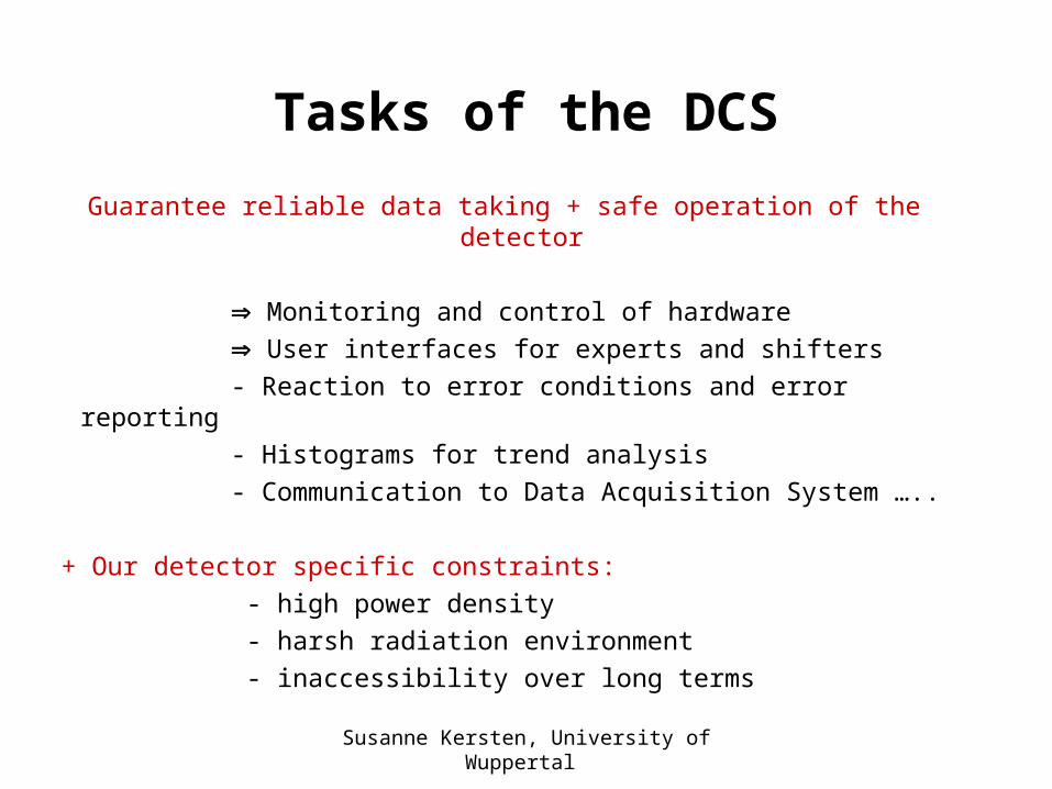
Overview of Pixel-DCS
Susanne Kersten, University of Wuppertal
Front End System
Susanne Kersten, University of Wuppertal
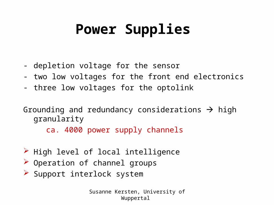
Power Supplies
- depletion voltage for the sensor- two low voltages for the front end electronics- three low voltages for the optolink
Grounding and redundancy considerations high granularity
ca. 4000 power supply channels
High level of local intelligence Operation of channel groups Support interlock system
Susanne Kersten, University of Wuppertal
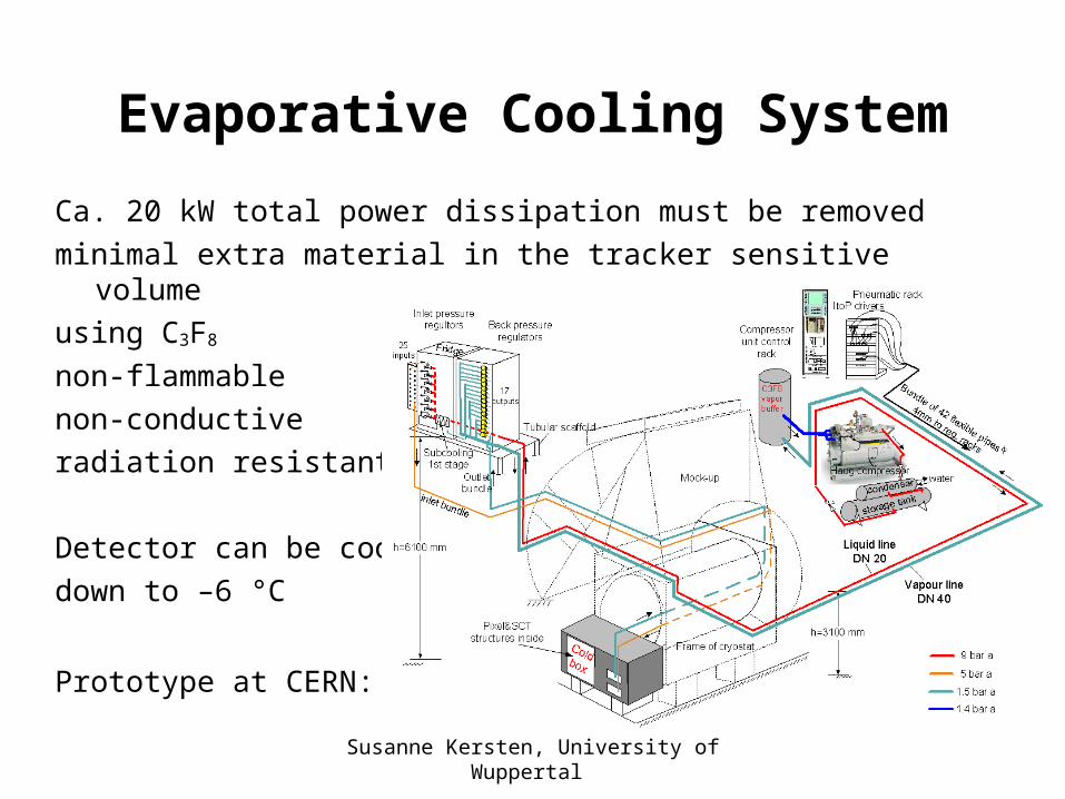
Evaporative Cooling System
Ca. 20 kW total power dissipation must be removedminimal extra material in the tracker sensitive volume using C3F8
non-flammablenon-conductive radiation resistant
Detector can be cooled down to –6 °C
Prototype at CERN:
Susanne Kersten, University of Wuppertal
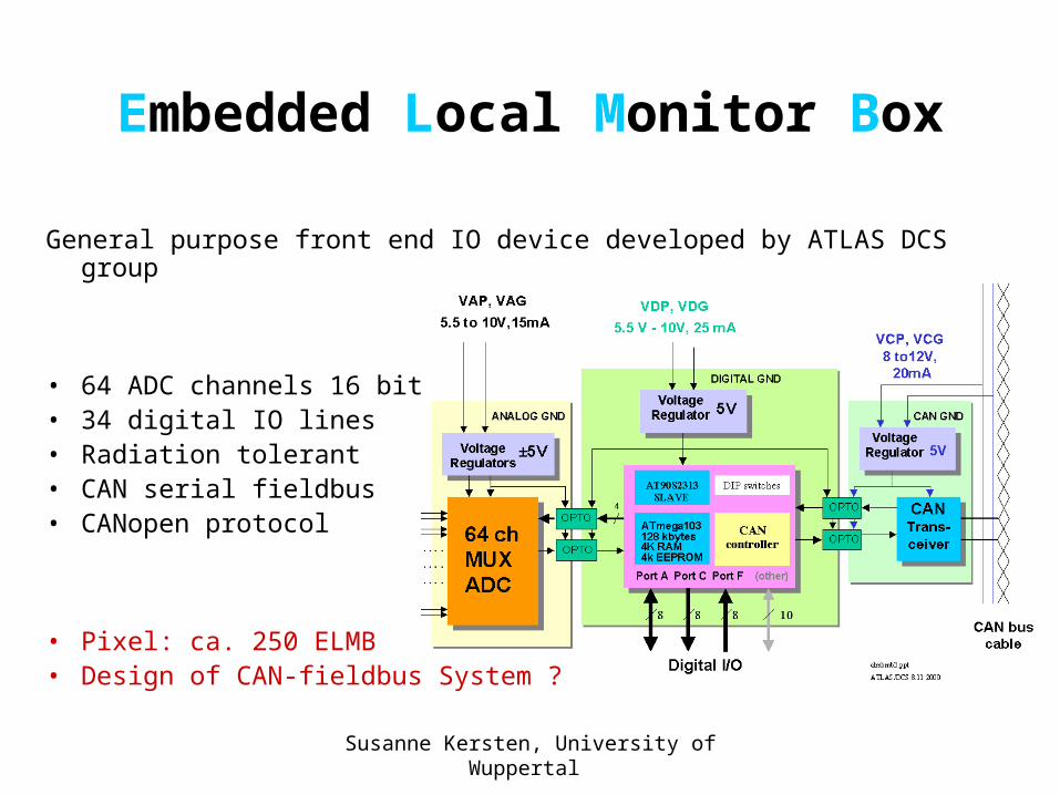
Embedded Local Monitor Box
General purpose front end IO device developed by ATLAS DCS group
• 64 ADC channels 16 bit• 34 digital IO lines• Radiation tolerant• CAN serial fieldbus• CANopen protocol
• Pixel: ca. 250 ELMB• Design of CAN-fieldbus System ?
Susanne Kersten, University of Wuppertal
Thermal Interlock System
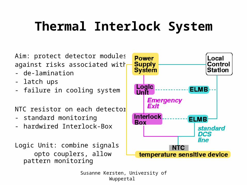
Aim: protect detector modulesagainst risks associated with - de-lamination- latch ups- failure in cooling system
NTC resistor on each detector- standard monitoring- hardwired Interlock-Box
Logic Unit: combine signals opto couplers, allow pattern
monitoring
Susanne Kersten, University of Wuppertal
The Interlock Box
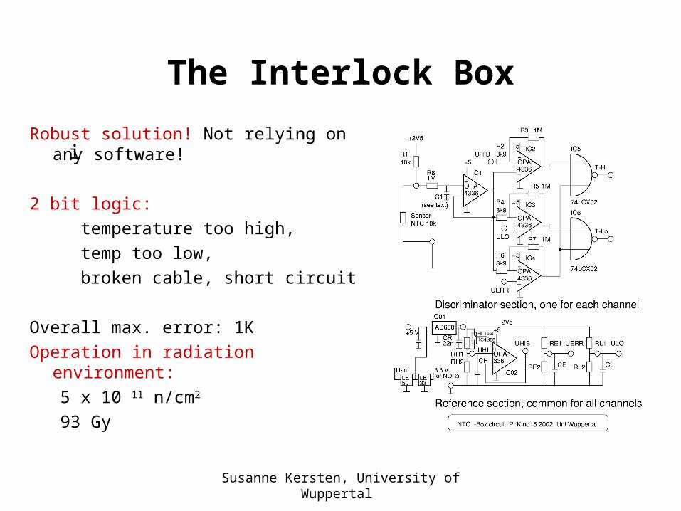
Robust solution! Not relying on any software!
2 bit logic: temperature too high, temp too low, broken cable, short circuit
Overall max. error: 1KOperation in radiation environment: 5 x 10 11 n/cm2
93 Gy
i
Susanne Kersten, University of Wuppertal
Mapping between Hardware components and Software
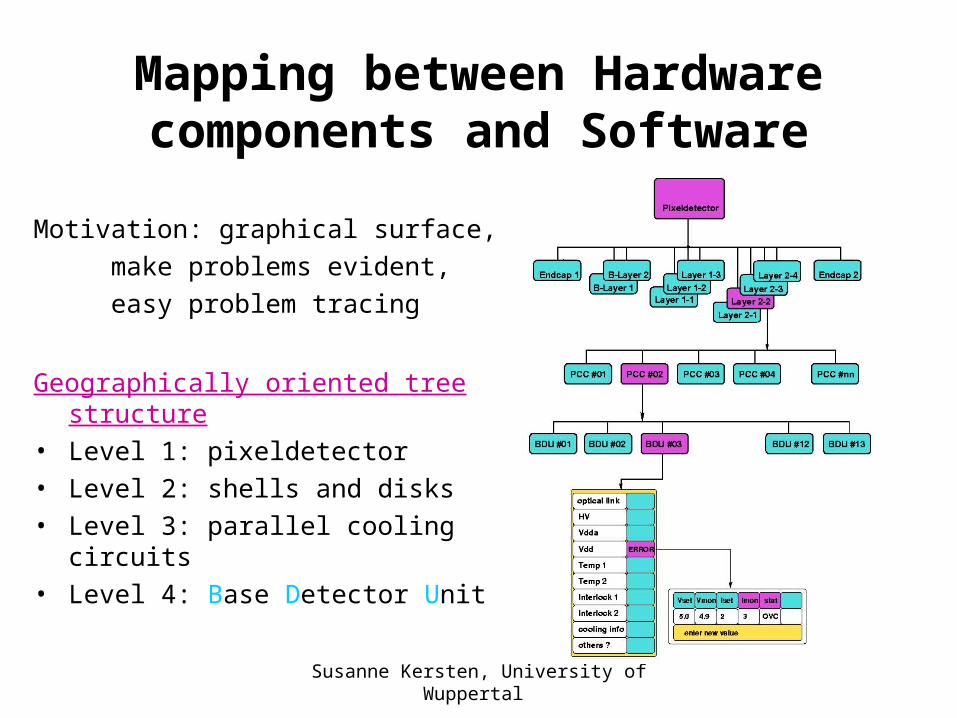
Motivation: graphical surface, make problems evident, easy problem tracing
Geographically oriented tree structure
• Level 1: pixeldetector• Level 2: shells and disks• Level 3: parallel cooling circuits• Level 4: Base Detector Unit
Susanne Kersten, University of Wuppertal
Back End System
Susanne Kersten, University of Wuppertal
Supervisory Control And Data Acquisition System:
PVSS
Commercial product PVSSII from ETM, AustriaLHC wide decision• Can be distributed over many stations• Flexible and open architecture• Basic functions for automatisation• Standardized interface to the hardware• Application programming interfaces
Susanne Kersten, University of Wuppertal
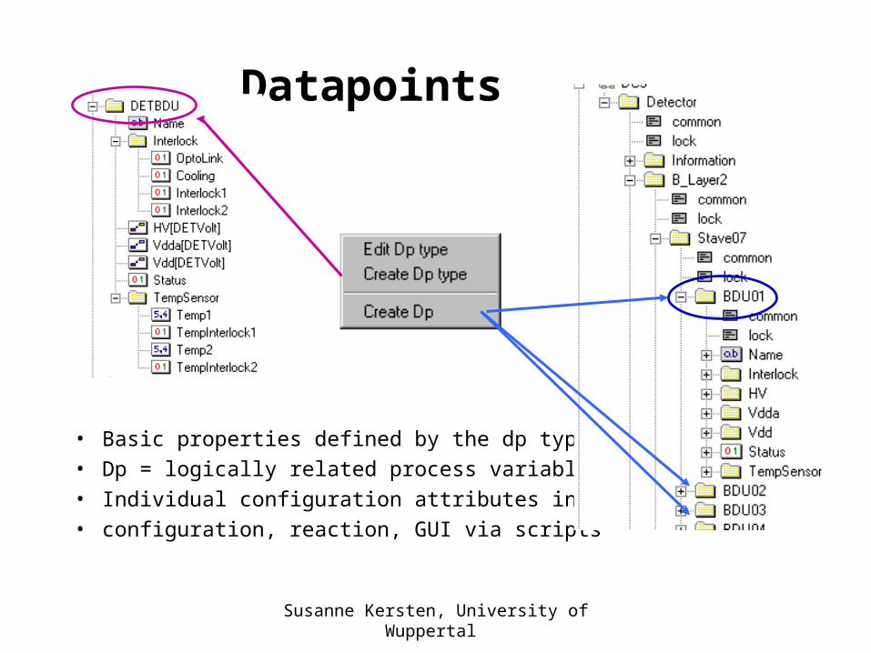
Datapoints
• Basic properties defined by the dp type• Dp = logically related process variable• Individual configuration attributes in dp• configuration, reaction, GUI via scripts
Susanne Kersten, University of Wuppertal
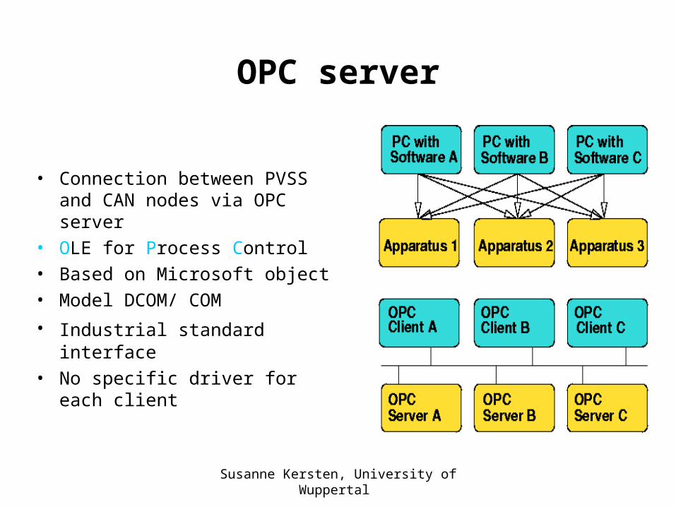
OPC server
• Connection between PVSS and CAN nodes via OPC server
• OLE for Process Control• Based on Microsoft object• Model DCOM/ COM
• Industrial standard interface• No specific driver for each
client
Susanne Kersten, University of Wuppertal
Testbeam Setup
Susanne Kersten, University of Wuppertal
Aims and Questions
• Support shifter with information • Experience with PVSS, are our needs covered by the
program• Temperature behaviour of detector module• System test for thermal interlock system• DCS and DAQ together
• Build a system which can be used for performance tests (operating parameters ..)
• Build a system which can easily be expanded • create basis for hierarchical structure - BDU
Susanne Kersten, University of Wuppertal
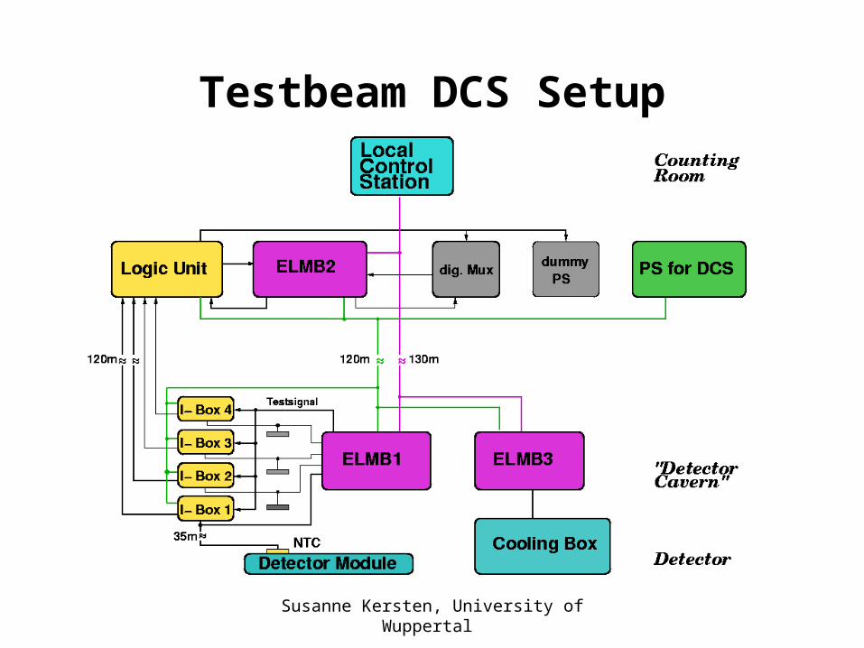
Testbeam DCS Setup
Susanne Kersten, University of Wuppertal
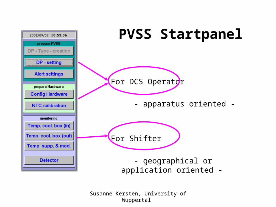
PVSS Startpanel
For DCS Operator - apparatus oriented -
For Shifter
- geographical or application oriented -
Susanne Kersten, University of Wuppertal
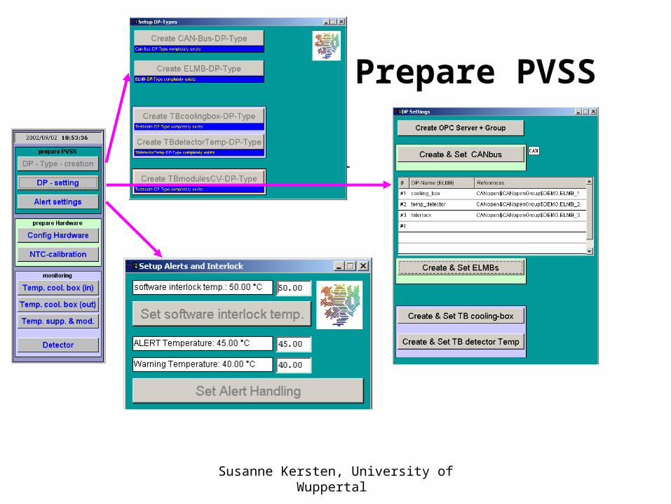
Prepare PVSS
• Start panel
Susanne Kersten, University of Wuppertal
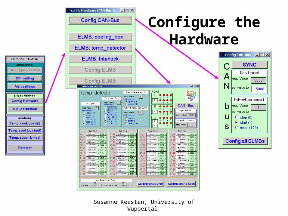
Configure the Hardware
Susanne Kersten, University of Wuppertal
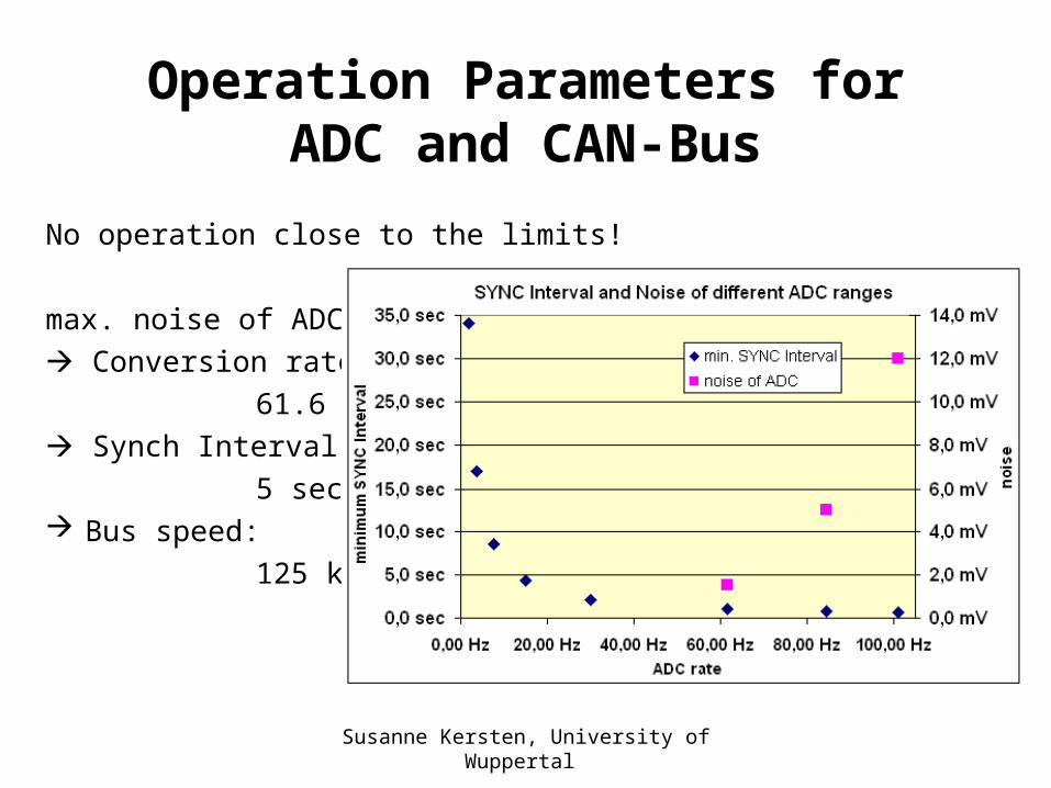
Operation Parameters for ADC and CAN-Bus
No operation close to the limits!
max. noise of ADC Conversion rate: 61.6 Hz Synch Interval: 5 sec Bus speed: 125 kBit/sec
Susanne Kersten, University of Wuppertal
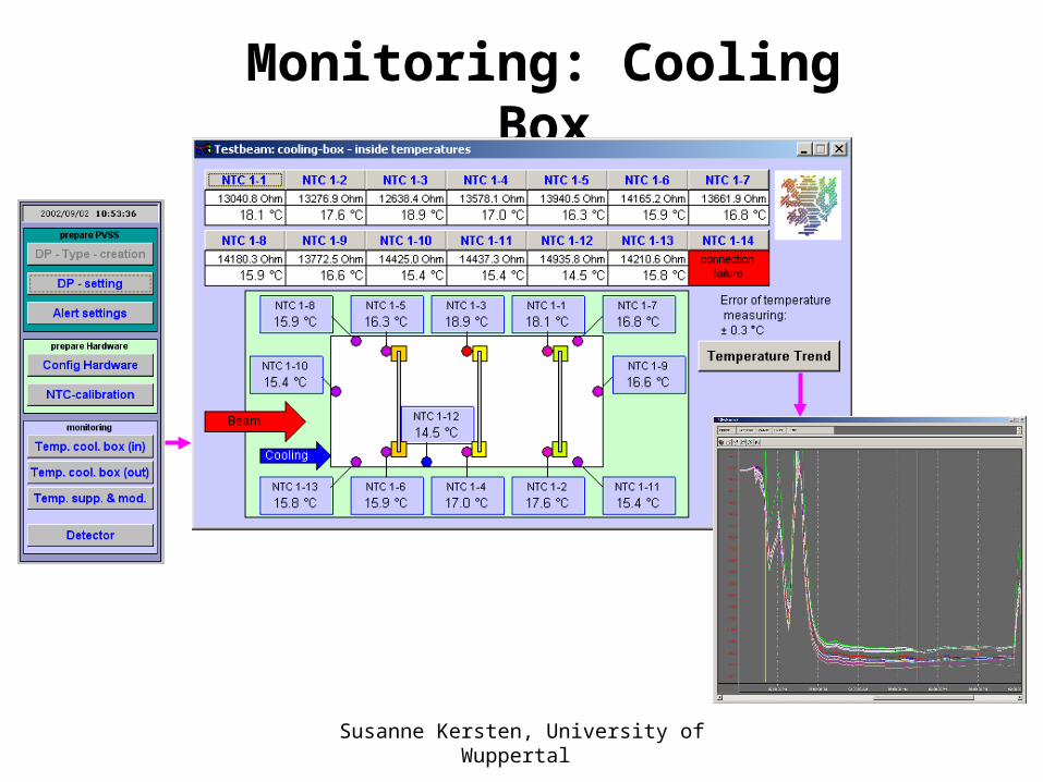
Monitoring: Cooling Box
Susanne Kersten, University of Wuppertal
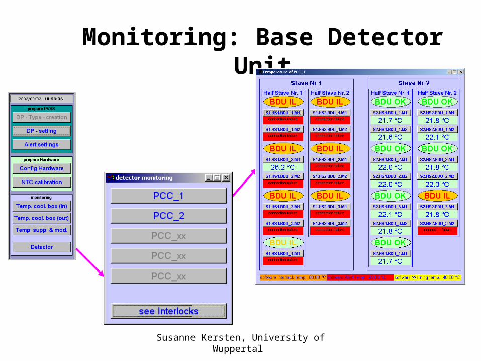
Monitoring: Base Detector Unit
Susanne Kersten, University of Wuppertal
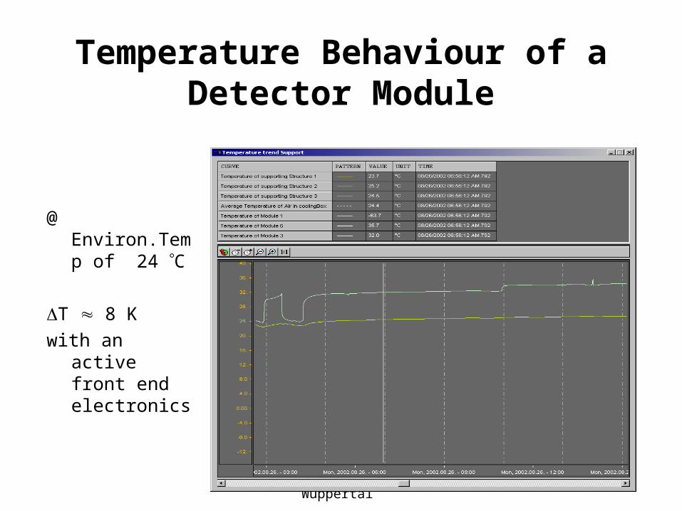
Temperature Behaviour of a Detector Module
@ Environ.Temp of 24 C
T 8 K with an active
front end electronics
Susanne Kersten, University of Wuppertal
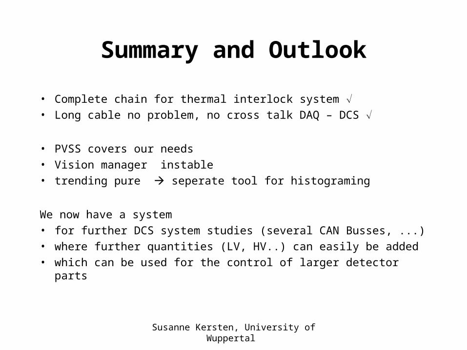
Summary and Outlook
• Complete chain for thermal interlock system • Long cable no problem, no cross talk DAQ – DCS
• PVSS covers our needs • Vision manager instable• trending pure seperate tool for histograming
We now have a system • for further DCS system studies (several CAN Busses, ...)• where further quantities (LV, HV..) can easily be added • which can be used for the control of larger detector parts


![Computational Vision Daniel Kersten Lecture 7: Image ...vision.psych.umn.edu/users/kersten/kersten-lab/... · testimage= ImageDataB F; Remember if you execute ImageData[< >]](https://img.pdfslide.us/doc/110x75/5fb588e8dd352c67bd5165e3/computational-vision-daniel-kersten-lecture-7-image-testimage-imagedatab-f.jpg)