Embed Size (px)
Citation preview

MAGUIRE PRODUCTS INC.
Weigh Scale Blender
For the Maguire Touchscreen Controller
Touch Screen Controller WEIGH SCALE BLENDER
TWELVE COMPONENT SOFTWARE INSTALLATION OPERATION MAINTENANCE
Copyright Maguire Products, Inc. 2017

M A G U I R E P R O D U C T S , I N C .
Edition: January 3, 2017 2
W E I G H S C A L E B L E N D E R

M A G U I R E P R O D U C T S , I N C .
Edition: Janauary 3, 2017 3
W E I G H S C A L E B L E N D E R
Copyright 2017 Maguire Products Inc. To every person concerned with use and maintenance of the Maguire Weigh Scale Blender it is recommended to read thoroughly these operating instructions. Maguire Products Inc. accepts no responsibility or liability for damage or malfunction of the equipment arising from non-observance of these operating instructions. To avoid errors and to ensure trouble-free operation, it is essential that these operating instructions are read and understood by all personnel who are to use the equipment. Should you have problems or difficulties with the equipment, please contact Maguire Products Inc. or your local Maguire distributor. These operating instructions only apply to the equipment described within this manual. Manufacturer’s Contact Information Maguire Products Inc. 11 Crozerville Road Aston, PA. 19014 Phone: 610.459.4300 Fax: 610.459.2700 Website: http://www.maguire.com Email: [email protected]
M A G U I R E P R O D U C T S , I N C .
Edition: January 3, 2017 4
W E I G H S C A L E B L E N D E R
Maguire Weigh Scale Blender 12 Software Operation & Maintenance Manual
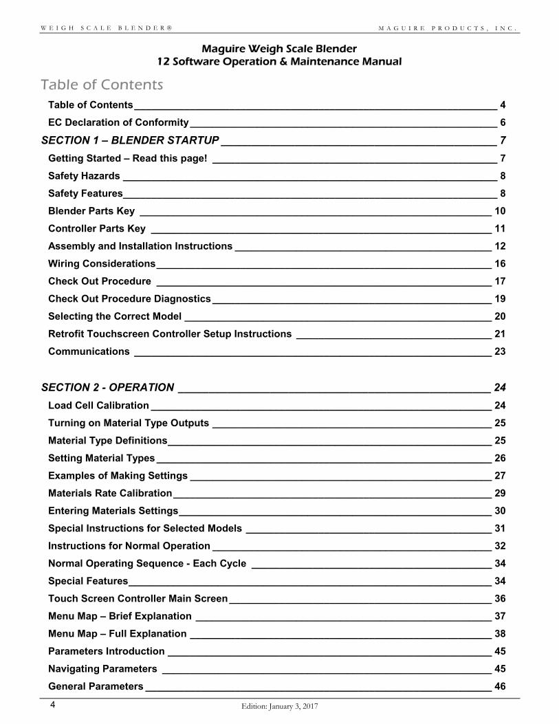
Table of Contents Table of Contents _________________________________________________________________ 4
EC Declaration of Conformity _______________________________________________________ 6
SECTION 1 – BLENDER STARTUP _____________________________________________ 7
Getting Started – Read this page! ___________________________________________________ 7
Safety Hazards ___________________________________________________________________ 8
Safety Features___________________________________________________________________ 8
Blender Parts Key _______________________________________________________________ 10
Controller Parts Key _____________________________________________________________ 11
Assembly and Installation Instructions ______________________________________________ 12
Wiring Considerations ____________________________________________________________ 16
Check Out Procedure ____________________________________________________________ 17
Check Out Procedure Diagnostics __________________________________________________ 19
Selecting the Correct Model _______________________________________________________ 20
Retrofit Touchscreen Controller Setup Instructions ___________________________________ 21
Communications ________________________________________________________________ 23
SECTION 2 - OPERATION ___________________________________________________ 24
Load Cell Calibration _____________________________________________________________ 24
Turning on Material Type Outputs __________________________________________________ 25
Material Type Definitions __________________________________________________________ 25
Setting Material Types ____________________________________________________________ 26
Examples of Making Settings ______________________________________________________ 27
Materials Rate Calibration _________________________________________________________ 29
Entering Materials Settings ________________________________________________________ 30
Special Instructions for Selected Models ____________________________________________ 31
Instructions for Normal Operation __________________________________________________ 32
Normal Operating Sequence - Each Cycle ___________________________________________ 34
Special Features _________________________________________________________________ 34
Touch Screen Controller Main Screen _______________________________________________ 36
Menu Map – Brief Explanation _____________________________________________________ 37
Menu Map – Full Explanation ______________________________________________________ 38
Parameters Introduction __________________________________________________________ 45
Navigating Parameters ___________________________________________________________ 45
General Parameters ______________________________________________________________ 46
M A G U I R E P R O D U C T S , I N C .
Edition: Janauary 3, 2017 5
W E I G H S C A L E B L E N D E R
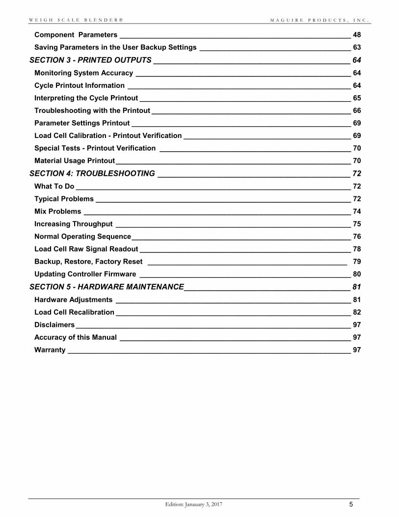
Component Parameters __________________________________________________________ 48
Saving Parameters in the User Backup Settings ______________________________________ 63
SECTION 3 - PRINTED OUTPUTS _____________________________________________ 64
Monitoring System Accuracy ______________________________________________________ 64
Cycle Printout Information ________________________________________________________ 64
Interpreting the Cycle Printout _____________________________________________________ 65
Troubleshooting with the Printout __________________________________________________ 66
Parameter Settings Printout _______________________________________________________ 69
Load Cell Calibration - Printout Verification __________________________________________ 69
Special Tests - Printout Verification ________________________________________________ 70
Material Usage Printout ___________________________________________________________ 70
SECTION 4: TROUBLESHOOTING ____________________________________________ 72
What To Do _____________________________________________________________________ 72
Typical Problems ________________________________________________________________ 72
Mix Problems ___________________________________________________________________ 74
Increasing Throughput ___________________________________________________________ 75
Normal Operating Sequence _______________________________________________________ 76
Load Cell Raw Signal Readout _____________________________________________________ 78
Backup, Restore, Factory Reset __________________________________________________ 79
Updating Controller Firmware _____________________________________________________ 80
SECTION 5 - HARDWARE MAINTENANCE ______________________________________ 81
Hardware Adjustments ___________________________________________________________ 81
Load Cell Recalibration ___________________________________________________________ 82
Disclaimers _____________________________________________________________________ 97
Accuracy of this Manual __________________________________________________________ 97
Warranty _______________________________________________________________________ 97
M A G U I R E P R O D U C T S , I N C .
Edition: January 3, 2017 6
W E I G H S C A L E B L E N D E R
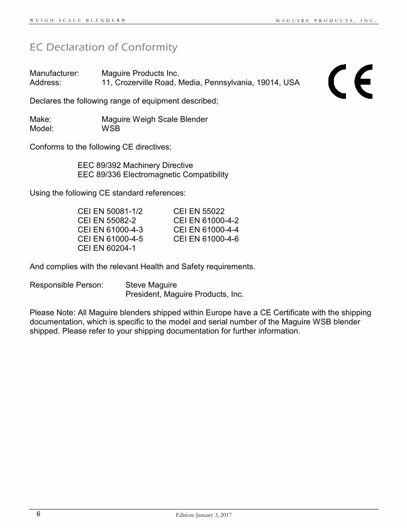
EC Declaration of Conformity
Manufacturer: Maguire Products Inc. Address: 11, Crozerville Road, Media, Pennsylvania, 19014, USA Declares the following range of equipment described; Make: Maguire Weigh Scale Blender Model: WSB Conforms to the following CE directives; EEC 89/392 Machinery Directive EEC 89/336 Electromagnetic Compatibility Using the following CE standard references:
CEI EN 50081-1/2 CEI EN 55022 CEI EN 55082-2 CEI EN 61000-4-2 CEI EN 61000-4-3 CEI EN 61000-4-4 CEI EN 61000-4-5 CEI EN 61000-4-6 CEI EN 60204-1
And complies with the relevant Health and Safety requirements. Responsible Person: Steve Maguire President, Maguire Products, Inc. Please Note: All Maguire blenders shipped within Europe have a CE Certificate with the shipping documentation, which is specific to the model and serial number of the Maguire WSB blender shipped. Please refer to your shipping documentation for further information.
M A G U I R E P R O D U C T S , I N C .
Edition: Janauary 3, 2017 7
W E I G H S C A L E B L E N D E R
SECTION 1 – BLENDER STARTUP Getting Started – Read this page!
THE NEXT SECTIONS OF THIS MANUAL WILL GUIDE YOU, STEP BY STEP, TO A SUCCESSFUL STARTUP. IT WON'T TAKE LONG; SO.... PLEASE, DON'T SKIP AHEAD. HERE ARE THE STEPS YOU WILL FOLLOW: SAFETY HAZARDS - Page 8 ……………………….. TWO HAZARDS exist on this unit: MIX BLADES and SLIDE VALVES. Read
this short sensible page so no one gets hurt. ASSEMBLY INSTRUCTIONS - Page 12 ……………. Very little assembly is required. But you might as well get it right the first
time. ALSO: Pay attention to the section on WIRING. CHECK OUT PROCEDURE - Page 17 ……………. This is to see if you did it right. It also will tell if anything was damaged in
shipping. LOAD CELL CALIBRATION - Page 22 …………… We already did this. But shipping or rough handling during assembly
sometimes creates load cell problems. If weight readings are not correct, you MUST recalibrate the load cells.
SETUP OUTPUTS & MATERIAL TYPES - Page 22.. To "TURN ON" a component, it must be designated as to TYPE, either
REGRIND, NATURAL, or ADDITIVE. Each is handled differently by the MATH routines. The controller MUST know the material TYPE to know what the setting means. This is IMPORTANT. Be SURE you UNDERSTAND this section before trying to operate your system.
RATE CALIBRATION - Page 27 …………………… This is NOT really necessary. But if your system uses non-standard
equipment, you MAY want to do this. SETTINGS & NORMAL OPERATION - Page 28 … From this point forward, operating your system is a snap. This section tells
you just how simple it is and exactly what to expect under normal operating conditions.
SPECIAL FEATURES - Page 29 …………………... Your system can do much more then you may know. This page reviews
briefly some of the added features that are available to you and where in this manual you can find them.
PROCEED TO: SAFETY HAZARDS NEXT PAGE
M A G U I R E P R O D U C T S , I N C .
Edition: January 3, 2017 8
W E I G H S C A L E B L E N D E R
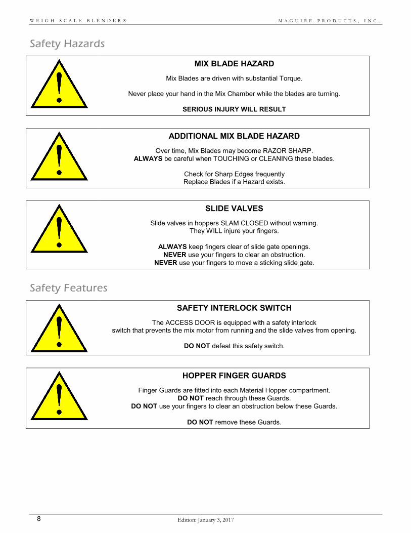
Safety Hazards
MIX BLADE HAZARD
Mix Blades are driven with substantial Torque.
Never place your hand in the Mix Chamber while the blades are turning.
SERIOUS INJURY WILL RESULT
ADDITIONAL MIX BLADE HAZARD
Over time, Mix Blades may become RAZOR SHARP. ALWAYS be careful when TOUCHING or CLEANING these blades.
Check for Sharp Edges frequently Replace Blades if a Hazard exists.
SLIDE VALVES
Slide valves in hoppers SLAM CLOSED without warning. They WILL injure your fingers.
ALWAYS keep fingers clear of slide gate openings.
NEVER use your fingers to clear an obstruction. NEVER use your fingers to move a sticking slide gate.
Safety Features
SAFETY INTERLOCK SWITCH
The ACCESS DOOR is equipped with a safety interlock switch that prevents the mix motor from running and the slide valves from opening.
DO NOT defeat this safety switch.
HOPPER FINGER GUARDS
Finger Guards are fitted into each Material Hopper compartment. DO NOT reach through these Guards.
DO NOT use your fingers to clear an obstruction below these Guards.
DO NOT remove these Guards.
M A G U I R E P R O D U C T S , I N C .
Edition: Janauary 3, 2017 9
W E I G H S C A L E B L E N D E R
M A G U I R E P R O D U C T S , I N C .
Edition: January 3, 2017 10
W E I G H S C A L E B L E N D E R
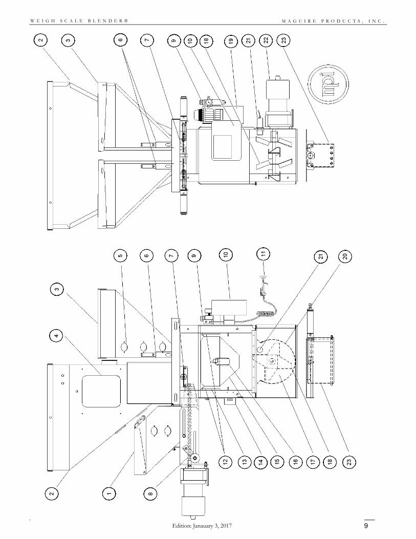
Blender Parts Key 1. Auger Feeder – Screw Feeder for feeding in small percentage materials such as Colors and Additives 2. Fixed Material Hopper – Material Hopper for main materials to be dosed by the slide gates
3. Removable Hopper – Removable Material hopper for small percentage materials such as Colors and
Additives
4. Hopper Access Door – Door to access inside of hopper for quick cleaning and materials changes
5. Sight Glass – Means to view current material level inside the hopper
6. Vertical Valve – Dispense Device mounted inside removable hopper for small percentages up to 10%
7. Slide Gate – Dispense Device mounted below fixed hoppers to dispense large percentages
8. Auger Screw – Dispense Device mounted inside removable hopper for small percentages up to 10%
9. Air Assembly & Solenoids – Pneumatic assembly for activating pneumatic parts automatically and manually
10. Controller – Central Controller for all settings on the blender
11. Cleaning Airline – Airline for quick and easy cleaning of blender during materials changes
12. Load Cells – Load Cells monitor continuously the weight in the Weigh Bin
13. Load Cell Bracket – Load Cell Bracket for mounting Weigh Bin onto the Load Cells
14. Safety Interlock – Pneumatic and Electrical Safety interlock – stops blender operating if door is opened
15. Weigh Bin – Weigh Bin holds materials as materials are dispensed during a batch and weighed
16. Dump Valve – Pneumatic Valve and Flap to release materials from Weigh Bin when a batch is complete
17. Mix Chamber – Area where materials are blended together after being weighed
18. Mix Blades – Removable Mix Blades to fold the materials together to achieve an effective blend
19. Power and Circuitry Box – Central box for power and support circuitry for controller.
20. Mix Chamber Insert – Stainless Steel removable insert to assist in quick materials cleaning and changes
21. Level Sensor – Sensor to monitor material level in the Mix Chamber, pauses blender when covered and mix chamber is full, once uncovered signals Controller to begin a new batch of material.
22. Mix Motor – Electric Motor to drive Mix Blades – Note on WSB MB and WSB 100 Series blenders this
motor is a pneumatic Mix Motor
23. Flow Control Valve – (Optional) – Additional pneumatic slide gate with finger guards to be used when blender is not mounted directly on the throat of a machine but instead a stand or surge hopper. The Flow Control Valve ensures material remains inside the Mix Chamber long enough to be mixed efficiently. Automatically controlled by the blender Controller.
M A G U I R E P R O D U C T S , I N C .
Edition: Janauary 3, 2017 11
W E I G H S C A L E B L E N D E R
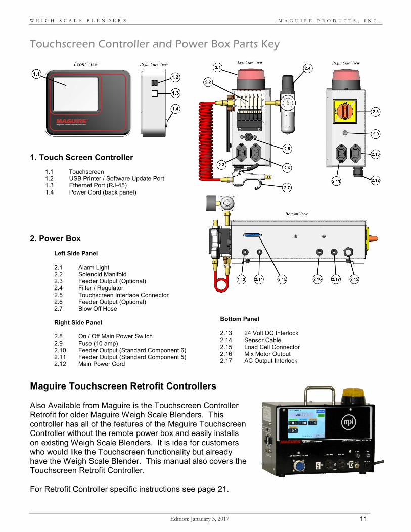
Touchscreen Controller and Power Box Parts Key
1. Touch Screen Controller
1.1 Touchscreen 1.2 USB Printer / Software Update Port 1.3 Ethernet Port (RJ-45) 1.4 Power Cord (back panel)
2. Power Box
Left Side Panel
2.1 Alarm Light 2.2 Solenoid Manifold 2.3 Feeder Output (Optional) 2.4 Filter / Regulator 2.5 Touchscreen Interface Connector 2.6 Feeder Output (Optional) 2.7 Blow Off Hose
Right Side Panel
2.8 On / Off Main Power Switch 2.9 Fuse (10 amp) 2.10 Feeder Output (Standard Component 6) 2.11 Feeder Output (Standard Component 5) 2.12 Main Power Cord
Bottom Panel 2.13 24 Volt DC Interlock 2.14 Sensor Cable 2.15 Load Cell Connector 2.16 Mix Motor Output 2.17 AC Output Interlock
Maguire Touchscreen Retrofit Controllers Also Available from Maguire is the Touchscreen Controller Retrofit for older Maguire Weigh Scale Blenders. This controller has all of the features of the Maguire Touchscreen Controller without the remote power box and easily installs on existing Weigh Scale Blenders. It is idea for customers who would like the Touchscreen functionality but already have the Weigh Scale Blender. This manual also covers the Touchscreen Retrofit Controller. For Retrofit Controller specific instructions see page 21.
M A G U I R E P R O D U C T S , I N C .
Edition: January 3, 2017 12
W E I G H S C A L E B L E N D E R
Assembly and Installation Instructions
CAUTION: LOAD CELLS ARE EASILY DAMAGED. If the FRAME is dropped from TWO FEET, the load cells WILL BE DAMAGED. THE WARRANTY DOES NOT COVER DAMAGED LOAD CELLS.
The following items have been shipped to you:
1. FRAME and HOPPER assembly: (bolted to skid) 2. CONTROLLER BOX: with the instruction manual. 3. FEEDER BOX: contains a COLOR or ADDITIVE feeder: optional. 4. FLOW CONTROL ASSEMBLY: optional 5. FLOOR STAND or VACUUM TAKEOFF ASSEMBLY: optional
RED INSTRUCTION STICKERS will assist you during assembly. LIFT HANGERS are available to allow lifting the blender with a strap or chain. Contact Maguire if you require them.
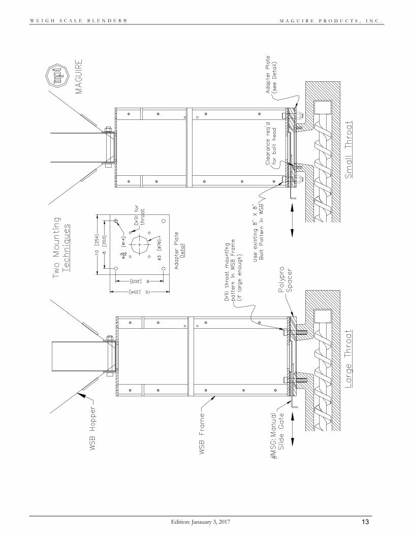
1A. If your unit is to be MACHINE mounted: For WSB MB, 100, 200, and 400 series models: Two ways to do this are suggested ON THE NEXT PAGE: The LEFT diagram shows the FRAME and SLIDE GATE both drilled with the proper bolt pattern for your machine and THROUGH BOLTED to your press. The RIGHT diagram shows only the 10 x 10 steel slide-gate plate drilled for your bolt pattern and bolted to your press. The FRAME is then bolted to it using the existing 8 x 8 inch bolt pattern holes and bolts provided. With this method, bolt head clearance holes are required in the poly-pro slide gate plate. This mounting works well on smaller machines. For WSB 900 and 1800 series models: An additional machine mount adaptor plate may be required. If you have ANY DOUBT about the STABILITY of the unit when bolted directly to your machine throat, please call us for advice.
NOTE: When choosing proper orientation, be sure to retain access to the controller and weigh chamber, clearance for hinged doors, and access to removable feeder hoppers.
1B. If your unit is STAND mounted: A stand is provided and your unit will bolt directly to it. An assembly DIAGRAM is provided on the following pages. An air operated FLOW CONTROL ASSEMBLY is provided for dispensing into a container. The purpose of this unit is to allow time for mixing to occur after each dispense. This flow valve keeps the mix chamber full to just below the sensor. This assembly bolts directly to the bottom of the Weigh Scale Blender frame.
M A G U I R E P R O D U C T S , I N C .
Edition: Janauary 3, 2017 13
W E I G H S C A L E B L E N D E R
M A G U I R E P R O D U C T S , I N C .
Edition: January 3, 2017 14
W E I G H S C A L E B L E N D E R
"Vac
uum
Tak
eoff
Assm
bly"
With
Opt
iona
l VTA
WSB
STA
ND
S
37-1
/4 [9
46]
51-1
/4 [1
302]
Barre
l
VTA
WSB
100
/200
/400
10-1
/8 [2
57]
AB
DC
25-7
/8 [6
57]
36 [9
14]
39-7
/8 [1
012]
8-1/
8 [2
06]
EF
Gay
lord
WSB
900
/180
0
51-7
/8 [1
318]
63-1
/4 [1
607]
56 [1
422]
VTA
Barre
l
Gay
lord
36 [9
14]
8 [2
03]
8 [2
03]
43-1
/4 [1
099]
69-1
/4 [1
759]
57-1
/4 [1
454]
16-1
/8 [4
10]
36 [9
14]
56 [1
422]
36 [9
14]
15 [3
81]
15 [3
81]
15 [3
81]
STAN
D D
IMEN
SIO
NS
NO
TE:
WSB
100
/200
/400
VTA
Sta
nd s
how
n to
sca
le.
10-1
/8 [2
57]
10-1
/8 [2
57]
8 [2
03]
8-1/
8 [2
06]
8-1/
8 [2
06]
14-1
/8 [3
59]
14-1
/8 [3
59]
14-1
/8 [3
59]
51-7
/8 [1
318]
39-7
/8 [1
012]
25-7
/8 [6
57]
16-1
/8 [4
10]
16-1
/8 [4
10]
M A G U I R E P R O D U C T S , I N C .
Edition: Janauary 3, 2017 15
W E I G H S C A L E B L E N D E R
2. Slide the WEIGH BIN into position. It rests behind the clear-hinged access window. Install with the air cylinder toward you. If bin is already in place, remove any shipping materials, packing tape or string.
3. Hang the Color and Additive Feeders: (Optional)
a. Lift side latches and fully extend slide assembly. Remove the hopper. Leave slide extended.
b. Tilting the entire slide assembly, motor end up, insert one corner of hanger cross bar behind frame corner post.
c. Rotate assembly into place so both ends of cross bar are behind corner posts. d. Lower into place, bottom edge resting on frame and cross bar properly positioned behind
corner posts. e. Re-install hopper. Slide motor forward until latches engage.
4. Connect the Touchscreen to the mounting wing and plug in Touchscreen cable
(7-pin connector).
5. Plug the power cord coming from the power box into a 110-volt power source (220 volt outside USA). This cord MUST provide the ONLY power source for the entire system, including the controller. See: WIRING CONSIDERATIONS, next page. 1800 series blenders also require a 240-volt power source for the mix motors.
6. Connect Compressed Air to the unit. About 80 psi (5.5 bar) is recommended (40 psi
for the Micro Blender). Lubricated air is NOT recommended.
NOTE: Micro Blenders should be set to 40 psi (2.7 bar). The Vertical Valves used in removable hoppers on Micro Blenders are more accurate at the lower 40 psi pressure setting.
7. Remove all protective paper from the plastic windows.
M A G U I R E P R O D U C T S , I N C .
Edition: January 3, 2017 16
W E I G H S C A L E B L E N D E R
Wiring Considerations
The wiring of your blender is very important to its proper operation. Electronics are very susceptible to voltage spikes and static charges, both of which are very common in plastics factories. To MINIMIZE these things, consider the following. The power supply should be solid; a strong supply, not limited by a "just adequate" control
transformer. A source of voltage that comes from a large transformer that supplies a large portion of the plant is better then a small power supply transformer that is intended to supply only this device. Power supplies, even though they may be "isolation" transformers, will still pass all voltage spikes right through. Their small size limits their ability to dampen RF (Radio Frequency) noise that is often induced into the system from outside sources. This proves worse then connection to larger central transformers.
Avoid running the power supply line along side any heavy power lines. An unshielded power supply in a raceway along side other heavy power lines will pick up induced RF noise and transfer it into the WSB steel enclosure causing computer trouble.
Long extension cords should be avoided. They also reduce the ability to provide a dampening
effect on spikes and static. The further the equipment is from a substantial power source, the more susceptible it is to spikes.
The CONTROLLER and the WSB frame MUST share the same GROUND PATH. This is why you
MUST plug the controller into the OUTLET that is provided ON THE FRAME.
REMOTE SYSTEMS. If you have your controller mounted in a remote location, you will have a number of power and signal cords running between the frame and the controller. BE SURE that the LOW VOLTAGE lines are NOT BUNDLED to the HIGH VOLTAGE lines and keep them away from other nearby electrical lines. LOW VOLTAGE lines are: Load Cell cable, Level Sensor cord, Air Solenoid cable, and Printer and communication cables. HIGH VOLTAGE lines are: Mixer motor cable, Feeder motors, and MAIN POWER line. Keep these sets of cables SEPARATED.
VACUUM LOADER CONVEYING LINES. Keep them away from all electrical lines, particularly the
Load Cell lines. Conveying plastic produces extreme static sources. A power supply line, even in conduit, that runs next to a vacuum line, can introduce extreme static pulses into the processor. Keep conveying lines SEPARATED from electrical supply lines.
We use many internal tooth "STAR" washers in assembling the WSB to ensure good ground
between painted parts. Do not remove them.
PROCEED TO: CHECK OUT PROCEDURE NEXT PAGE
M A G U I R E P R O D U C T S , I N C .
Edition: Janauary 3, 2017 17
W E I G H S C A L E B L E N D E R
Check Out Procedure
As you go through this procedure, if WHAT SHOULD HAPPEN, doesn't happen, see next section, DIAGNOSTICS, for what to check.
MB/100/200 series models (3K load cells), display all weights in 1/10 grams (xxxx.x). 400/900/1800 series models (10K load cells) display weights in FULL grams, NO decimal point (xxxxx). On this page we show all weights with NO decimal point.
Start with NO MATERIAL in any hoppers. Be sure an AIR SUPPLY is connected. Turn POWER SWITCH OFF (on side of Power Box). PROCEDURE: WHAT SHOULD HAPPEN: 1. POWER UP CONTROLLER / Blender PLUG IN CONTROLLER Nothing should happen.
Air pressure should be holding ALL valves CLOSED. This means all air cylinders are extended. If any slide gate or flap is open, air lines are reversed. If a FLOW CONTROL VALVE is installed, check it.
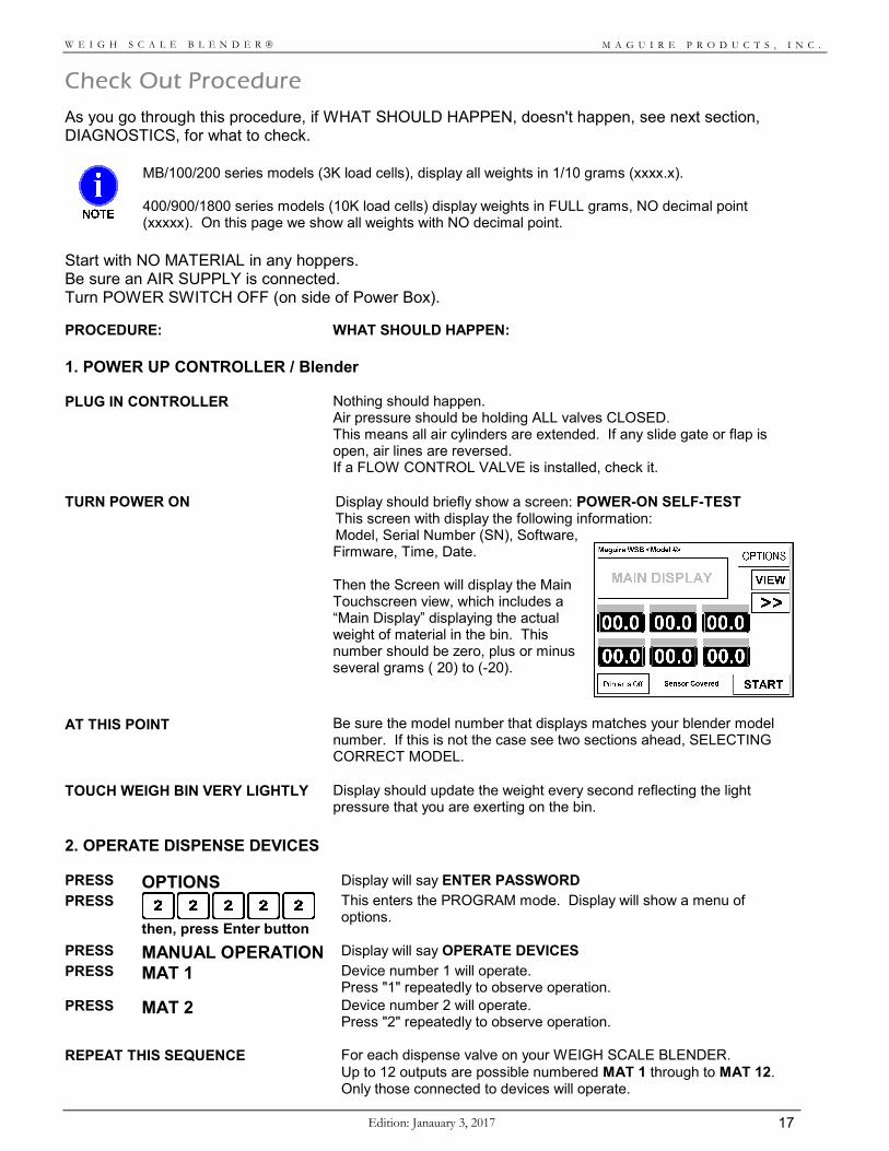
TURN POWER ON Display should briefly show a screen: POWER-ON SELF-TEST This screen with display the following information: Model, Serial Number (SN), Software, Firmware, Time, Date. Then the Screen will display the Main Touchscreen view, which includes a “Main Display” displaying the actual weight of material in the bin. This number should be zero, plus or minus several grams ( 20) to (-20).
AT THIS POINT
Be sure the model number that displays matches your blender model number. If this is not the case see two sections ahead, SELECTING CORRECT MODEL.
TOUCH WEIGH BIN VERY LIGHTLY
Display should update the weight every second reflecting the light pressure that you are exerting on the bin.
2. OPERATE DISPENSE DEVICES PRESS OPTIONS Display will say ENTER PASSWORD
PRESS
then, press Enter button
This enters the PROGRAM mode. Display will show a menu of options.
PRESS MANUAL OPERATION Display will say OPERATE DEVICES
PRESS
MAT 1 Device number 1 will operate. Press "1" repeatedly to observe operation.
PRESS
MAT 2 Device number 2 will operate. Press "2" repeatedly to observe operation.
REPEAT THIS SEQUENCE
For each dispense valve on your WEIGH SCALE BLENDER. Up to 12 outputs are possible numbered MAT 1 through to MAT 12. Only those connected to devices will operate.
M A G U I R E P R O D U C T S , I N C .
Edition: January 3, 2017 18
W E I G H S C A L E B L E N D E R
3. NOTE HOPPER NUMBERS AT THIS POINT
NOTE which component NUMBER is assigned to each hopper. You will want to know each hopper's correct component number.
FOR WSB 940 & WSB 1840 SERIES:
On 9000 and 18000 gram, FOUR hopper compartment systems, facing the Controller side of the blender: Device 1 is the NEAR hopper, 2 the FAR hopper, 3 the LEFT CENTER, and 4 the RIGHT CENTER hopper.
FOR WSB 100, 200 & 400 SERIES:
On 1000, 2000, and 4000 gram, FOUR hopper systems facing the Controller side of the blender: Devices 1, 2, 3, and 4 are counter-clockwise starting with far left corner hopper.
FOR WSB 200, 400, 900 & 1800 SERIES:
On 2000, 4000, 9000 and 18000 gram SIX hopper systems facing the Controller side of the blender: Devices 1, 2, 3, 4, 7, and 8 are counter-clockwise starting with far left corner hopper.
FOR WSB 100, 200, 400, 900 & 1800 SERIES:
On the blender Controller: Device 5 is the LEFT Panel-front OUTLET. Device 6 is the RIGHT Panel-front OUTLET.
4. OPERATE OTHER DEVICES PRESS
DUMP The weigh bin air solenoid will operate. The weigh bin dump valve will open. Press, "DUMP" repeatedly to observe operation.
PRESS
MIX This key controls the mix motor outlet on the side of the controller. The mixer motor will run. Mix blade turns clockwise facing the motor shaft or 270º on Pneumatic Mix Motors. Mixer switch must be down; timed position.
PRESS HOLD The Flow Control Valve will operate. (Under the mix chamber - this device is optional)
PRESS ALARM The Strobe light and Beeper will operate. Display will show ALARM: ON
PRESS
Press twice, to return to normal mode. Verify normal mode by observing that the display is back to the Main Touchscreen display.
If you have made it this far, congratulations. You have done well. The load cells and controller are functioning properly.
LOAD CELL CALIBRATION – SKIP TO PAGE 27
M A G U I R E P R O D U C T S , I N C .
Edition: Janauary 3, 2017 19
W E I G H S C A L E B L E N D E R
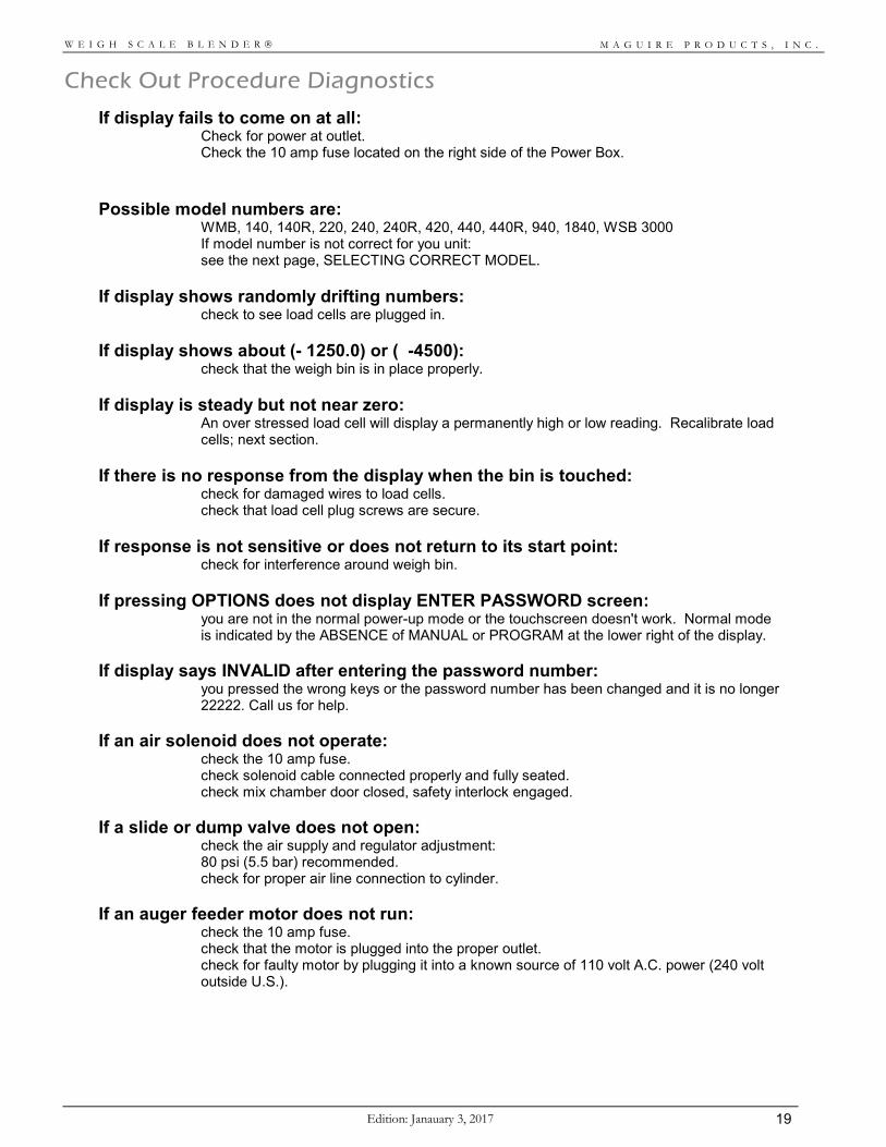
Check Out Procedure Diagnostics
If display fails to come on at all: Check for power at outlet.
Check the 10 amp fuse located on the right side of the Power Box. Possible model numbers are: WMB, 140, 140R, 220, 240, 240R, 420, 440, 440R, 940, 1840, WSB 3000
If model number is not correct for you unit: see the next page, SELECTING CORRECT MODEL.
If display shows randomly drifting numbers: check to see load cells are plugged in. If display shows about (- 1250.0) or ( -4500): check that the weigh bin is in place properly. If display is steady but not near zero: An over stressed load cell will display a permanently high or low reading. Recalibrate load
cells; next section. If there is no response from the display when the bin is touched: check for damaged wires to load cells.
check that load cell plug screws are secure. If response is not sensitive or does not return to its start point: check for interference around weigh bin. If pressing OPTIONS does not display ENTER PASSWORD screen: you are not in the normal power-up mode or the touchscreen doesn't work. Normal mode
is indicated by the ABSENCE of MANUAL or PROGRAM at the lower right of the display. If display says INVALID after entering the password number: you pressed the wrong keys or the password number has been changed and it is no longer
22222. Call us for help. If an air solenoid does not operate: check the 10 amp fuse.
check solenoid cable connected properly and fully seated. check mix chamber door closed, safety interlock engaged.
If a slide or dump valve does not open: check the air supply and regulator adjustment:
80 psi (5.5 bar) recommended. check for proper air line connection to cylinder.
If an auger feeder motor does not run: check the 10 amp fuse.
check that the motor is plugged into the proper outlet. check for faulty motor by plugging it into a known source of 110 volt A.C. power (240 volt outside U.S.).
M A G U I R E P R O D U C T S , I N C .
Edition: January 3, 2017 20
W E I G H S C A L E B L E N D E R
Selecting the Correct Model
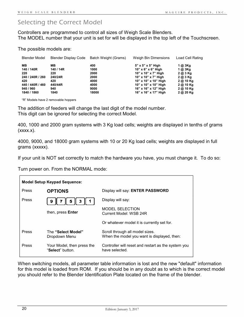
Controllers are programmed to control all sizes of Weigh Scale Blenders. The MODEL number that your unit is set for will be displayed in the top left of the Touchscreen. The possible models are:
Blender Model Blender Display Code Batch Weight (Grams) Weigh Bin Dimensions Load Cell Rating MB MB 400 5” x 5” x 5” High 1 @ 3Kg 140 / 140R 140 / 14R 1000 10” x 6” x 6” High 1 @ 3Kg 220 220 2000 10” x 10” x 7” High 2 @ 3 Kg 240 / 240R / 260 240/24R 2000 10” x 10” x 7” High 2 @ 3 Kg 420 420 4000 10” x 10” x 10” High 2 @ 10 Kg 440 / 440R / 460 440/44R 4000 10” x 10” x 10” High 2 @ 10 Kg 940 / 960 940 9000 16” x 16” x 12” High 2 @ 10 Kg 1840 / 1860 1840 18000 16” x 16” x 17” High 2 @ 20 Kg “R” Models have 2 removable hoppers
The addition of feeders will change the last digit of the model number. This digit can be ignored for selecting the correct Model. 400, 1000 and 2000 gram systems with 3 Kg load cells; weights are displayed in tenths of grams (xxxx.x). 4000, 9000, and 18000 gram systems with 10 or 20 Kg load cells; weights are displayed in full grams (xxxxx). If your unit is NOT set correctly to match the hardware you have, you must change it. To do so: Turn power on. From the NORMAL mode:
Model Setup Keypad Sequence:
Press OPTIONS Display will say: ENTER PASSWORD
Press
then, press Enter
Display will say: MODEL SELECTION Current Model: WSB 24R Or whatever model it is currently set for.
Press The “Select Model” Dropdown Menu
Scroll through all model sizes. When the model you want is displayed, then:
Press Your Model, then press the “Select” button.
Controller will reset and restart as the system you have selected.
When switching models, all parameter table information is lost and the new "default" information for this model is loaded from ROM. If you should be in any doubt as to which is the correct model you should refer to the Blender Identification Plate located on the frame of the blender.
M A G U I R E P R O D U C T S , I N C .
Edition: Janauary 3, 2017 21
W E I G H S C A L E B L E N D E R
Touchscreen Controller Retrofit Instructions
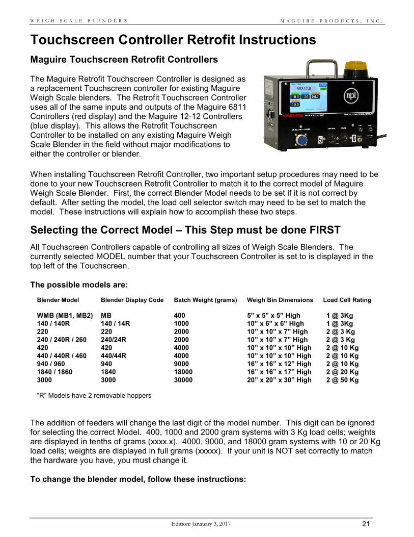
Maguire Touchscreen Retrofit Controllers The Maguire Retrofit Touchscreen Controller is designed as a replacement Touchscreen controller for existing Maguire Weigh Scale blenders. The Retrofit Touchscreen Controller uses all of the same inputs and outputs of the Maguire 6811 Controllers (red display) and the Maguire 12-12 Controllers (blue display). This allows the Retrofit Touchscreen Controller to be installed on any existing Maguire Weigh Scale Blender in the field without major modifications to either the controller or blender.
When installing Touchscreen Retrofit Controller, two important setup procedures may need to be done to your new Touchscreen Retrofit Controller to match it to the correct model of Maguire Weigh Scale Blender. First, the correct Blender Model needs to be set if it is not correct by default. After setting the model, the load cell selector switch may need to be set to match the model. These instructions will explain how to accomplish these two steps.
Selecting the Correct Model – This Step must be done FIRST
All Touchscreen Controllers capable of controlling all sizes of Weigh Scale Blenders. The currently selected MODEL number that your Touchscreen Controller is set to is displayed in the top left of the Touchscreen. The possible models are:
Blender Model Blender Display Code Batch Weight (grams) Weigh Bin Dimensions Load Cell Rating WMB (MB1, MB2) MB 400 5” x 5” x 5” High 1 @ 3Kg 140 / 140R 140 / 14R 1000 10” x 6” x 6” High 1 @ 3Kg 220 220 2000 10” x 10” x 7” High 2 @ 3 Kg 240 / 240R / 260 240/24R 2000 10” x 10” x 7” High 2 @ 3 Kg 420 420 4000 10” x 10” x 10” High 2 @ 10 Kg 440 / 440R / 460 440/44R 4000 10” x 10” x 10” High 2 @ 10 Kg 940 / 960 940 9000 16” x 16” x 12” High 2 @ 10 Kg 1840 / 1860 1840 18000 16” x 16” x 17” High 2 @ 20 Kg 3000 3000 30000 20” x 20” x 30” High 2 @ 50 Kg “R” Models have 2 removable hoppers
The addition of feeders will change the last digit of the model number. This digit can be ignored for selecting the correct Model. 400, 1000 and 2000 gram systems with 3 Kg load cells; weights are displayed in tenths of grams (xxxx.x). 4000, 9000, and 18000 gram systems with 10 or 20 Kg load cells; weights are displayed in full grams (xxxxx). If your unit is NOT set correctly to match the hardware you have, you must change it. To change the blender model, follow these instructions:
M A G U I R E P R O D U C T S , I N C .
Edition: January 3, 2017 22
W E I G H S C A L E B L E N D E R
Turn power on. From the NORMAL mode:
Model Setup Keypad Sequence:
Press OPTIONS Display will say: ENTER PASSWORD
Press
then, press Enter
Display will say: MODEL SELECTION Current Model: WSB 24R Or whatever model it is currently set for.
Press The “Select Model” Dropdown Menu
Scroll through all model sizes. When the model you want is displayed, then:
Press Your Model, then press the “Select” button.
Controller will reset and restart as the system you have selected.
When switching models, all parameter table information is lost and the new "default" information for this model is loaded from ROM. If you should be in any doubt as to which is the correct model you should refer to the Blender Identification Plate located on the frame of the Blender.
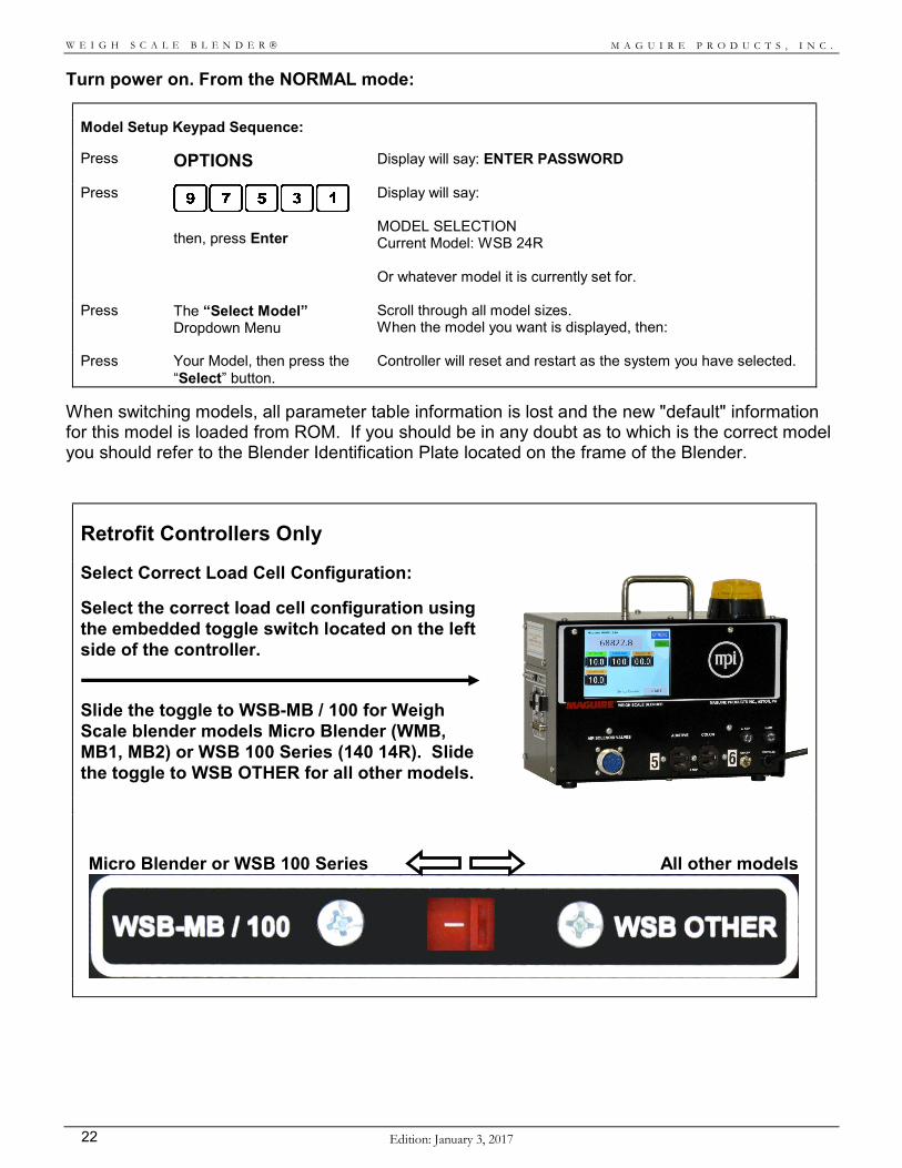
Retrofit Controllers Only
Select Correct Load Cell Configuration:
Select the correct load cell configuration using the embedded toggle switch located on the left side of the controller. Slide the toggle to WSB-MB / 100 for Weigh Scale blender models Micro Blender (WMB, MB1, MB2) or WSB 100 Series (140 14R). Slide the toggle to WSB OTHER for all other models.
Micro Blender or WSB 100 Series All other models
M A G U I R E P R O D U C T S , I N C .
Edition: Janauary 3, 2017 23
W E I G H S C A L E B L E N D E R
Communications
The Maguire Weigh Scale Blenders are capable of two-way communications for enhanced control and data collection. The Maguire Weigh Scale Blender's Controller itself uses Maguire's MLAN Protocol to send and receive data through commands within the protocol. All Maguire Controllers use either an Ethernet port or an RS-232 (MLAN) port for communications. The Maguire Touchscreen Controller has an Ethernet port, located on the right side of the controller. Through this communication port information can be sent to or gathered from the Maguire Weigh Scale Blenders. The standard protocol for communication with the Maguire Weigh Scale Blenders is the MLAN Protocol. Several options are available for methods of communication, all of which use the MLAN Protocol. Communication options are: Direct MLAN Protocol, OPC (OLE for Process Control) or the Gravimetric Gateway Software. For more information on these options visit www.Maguire.com or contact your local Maguire representative. The MLAN Protocol (Maguire Local Area Network) is a protocol consisting of commands that allows two-way communications to the Maguire Weigh Scale Blenders. All Maguire Weigh Scale Blenders dated back to 1992 contain the essential MLAN commands for basic control and data collection while newer Maguire controllers contain additional commands for enhanced control and data collection. The MLAN Protocol was initially intended to provide information for individuals who are writing software for Programmable Logic Controllers (PLCs) and needed to communicate with the Maguire Weigh Scale Blender. The Protocol is available for free and is explained in detail in our MLAN Protocol Manual (available at www.Maguire.com). Customers who wish to write their own software to communicate directly with the Maguire Weigh Scale Blenders will need the MLAN Protocol Manual.
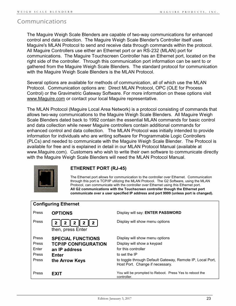
ETHERNET PORT (RJ-45) The Ethernet port allows for communication to the controller over Ethernet. Communication through this port is TCP/IP utilizing the MLAN Protocol. The G2 Software, using the MLAN Protocol, can communicate with the controller over Ethernet using this Ethernet port. All G2 communications with the Touchscreen controller though the Ethernet port communicate over a user specified IP address and port 9999 (unless port is changed).
Configuring Ethernet
Press OPTIONS Display will say: ENTER PASSWORD
Press
then, press Enter
Display will show menu options
Press SPECIAL FUNCTIONS Display will show menu options
Press TCP/IP CONFIGURATION Display will show a keypad
Enter an IP address for this controller
Press Enter to set the IP
Press the Arrow Keys to toggle through Default Gateway, Remote IP, Local Port, Host Port. Change if necessary.
Press EXIT You will be prompted to Reboot. Press Yes to reboot the controller.
M A G U I R E P R O D U C T S , I N C .
Edition: January 3, 2017 24
W E I G H S C A L E B L E N D E R
SECTION 2 - OPERATION Load Cell Calibration
Displays shown here are in full grams. MB, 100 and 200 series models are in 1/10 grams, with a decimal.
If your load cells already display a weight close to zero, plus or minus 10 grams, you may skip this section and go directly to: TURNING ON OUTPUTS (next page). If your unit DOES NOT display an acceptable weight, you should recalibrate them, that is reset your ZERO weight, at this time. To do so: BE SURE the weigh bin is EMPTY. BE SURE the load cell plug is plugged into the side of the controller. BE SURE the weigh bin is resting on the load cells freely. BE SURE the air line to the dump valve is connected as it would be during normal operation. A disconnected
air line adds weight. BE SURE The load cells and bin are not jammed in any way. To test for this see that a light touch on the bin
causes the display to change. When the pressure is removed the display must return to exactly where it was, plus or minus 1 gram. If this does not happen, something is touching something and the bin is not entirely free to move. Check EVERYTHING around the bin.
LOAD CELL CALIBRATION: The sequence of keystrokes is as follows:
Load Cell Zero Calibration Keypad Sequence:
Press OPTIONS Display will say: ENTER PASSWORD
Press
then, press Enter
Display will show menu options
Press SPECIAL FUNCTIONS Display will show menu options
Press SETUP Display will show menu options
Press Calibrate Load Cells
Press SET ZERO WT Display will say: Confirm weigh bin is empty then press: YES (weigh bin can be dumped using DUMP BIN button). Followed by a gram weight of 0
Press
Display will say: WAITING
The ZERO point of the load cells is now set properly. FULL weight calibration may also be done at this time, however, it probably is NOT NECESSARY. When load cell readings shift due to rough handling, the entire range of readings from ZERO to FULL shift together. The ZERO weight calibration routine resets the full range of the cells and, therefore, corrects FULL weight readings as well. For information on FULL weight calibration, see RECALIBRATION OF LOAD CELLS.
PROCEED TO: TURNING ON OUTPUTS and MATERIAL TYPES NEXT PAGE
M A G U I R E P R O D U C T S , I N C .
Edition: Janauary 3, 2017 25
W E I G H S C A L E B L E N D E R
Turning on Material Type Outputs This controller can control up to TWELVE (12) components; 1 through 12. Labeled: MAT 1 through MAT 12 (MAT = MATERIAL). You must "TURN ON" the COMPONENT outputs that you are going to use. Components that are TURNED OFF are not part of ANY routines. A component becomes TURNED ON when it is set to a MATERIAL TYPE.
Material Type Definitions Material TYPES are REGRIND, NATURAL, and ADDITIVE. The WEIGH SCALE BLENDER handles each TYPE DIFFERENTLY. Settings have different meanings for each TYPE. To enter SETTINGS correctly, you MUST UNDERSTAND how different materials are handled based on their TYPE. So PLEASE read this page CAREFULLY. Material TYPES are explained here. How to set them is explained on the next page.
REGRIND (PERCENT OF MIX) Components designated REGRIND will be added as a PERCENT of the ENTIRE MIX of material. For example, If component 1 is designated as REGRIND and is set for 20.0 percent, then for every 100 pounds of blend, 20 pounds will be this component.
NATURAL (RATIO TO EACH OTHER) Components designated NATURAL will be added in the proportion that you specify them to each other. Their actual percentage of the mix will depend on how much Regrind is specified and how much Additive is specified. For example, if components 2 and 3 are both designated NATURAL and are set for 10 and 40 respectively, then the RATIO of component 2 to component 3 will always be 10 to 40 or 1 to 4. If no Regrind or Additives are specified, the mix will be:
Component 2, NATURAL, SET= 10, 20.0 percent of mix, Component 3, NATURAL, SET= 40, 80.0 percent of mix.
The RATIO of 1 to 4 is maintained. If component 1 is specified as REGRIND at 20 percent, the mix is then
Component 1, REGRIND, SET= 20, 20 percent of mix, Component 2, NATURAL, SET= 10, 16.0 percent of mix, Component 3, NATURAL, SET= 40, 64.0 percent of mix.
Components 2 and 3 are still held at a 1 to 4 ratio.
ADDITIVE (PERCENT OF ALL NATURALS) Components designated ADDITIVE will be added as a percentage of all the NATURALS added together. For example: If component 5 is an ADDITIVE at 5 percent, then the above example now looks like this:
Component 1, REGRIND, SET= 20, 20 percent, Component 2, NATURAL, SET= 10, 15.2 percent, Component 3, NATURAL, SET= 40, 61.0 percent, Component 4, ADDITIVE, SET= 05.0, 3.8 percent.
The REGRIND is still 20 percent of the MIX. The NATURALS are still at a RATIO of 1 to 4, although they have been reduced to make room for the Additive. The ADDITIVE is 5 percent of the NATURALS added together (5% of 76.2).
WHY do we do it this way? Because this is how most plastic processors think of these components. REGRIND is generally only added when available, and then as a limited percentage of the entire mix. NATURALS are generally blended at a RATIO to one another. ADDITIVES are most often only intended to be added to the entire NATURAL portion of the mix, because regrind generally already contains these additives.
M A G U I R E P R O D U C T S , I N C .
Edition: January 3, 2017 26
W E I G H S C A L E B L E N D E R
ON THE OTHER HAND: If you prefer to think of your mix as a RATIO OF WEIGHTS, for example, components 1, 2, 3, 4, and 5 are to be mixed at 100, 50, 5, 20 and 7 pounds respectively, then you may wish to specify ALL components as NATURALS. In this way these weights may be entered just as listed here. Components will be dispensed to maintain each at the proper specified RATIO to the other components. If you wish to think of all components as PERCENTAGES of THE MIX, percents that always add up to 100 specify ALL components as REGRIND and enter the exact percent for each. When ALL components are REGRINDS, ALL settings must add up to 99.9 or 100 percent. If they do not, an error message (REG >100) or (REG <100) will appear. BUT... WE RECOMMEND that you do it this way: REGRIND Use this for all materials that DO NOT require the addition of the ADDITIVES. For example, your Regrind scrap. NATURAL Use this for all materials that are the bulk of the mix.
These will be RATIOED to each other and will automatically constitute the ENTIRE mix except for the space needed for Regrind and Additives. A blend of ABS Homo-polymer and Co-polymer or a blend of Styrene Hi Impact and Crystal are examples of NATURALS ratioed together.
ADDITIVES Use this for all materials that are added to the NATURALS only.
For example; color, stabilizer, slip agent, etc.
Setting Material Types The sequence to set MATERIAL TYPES is:
Set Material Types Keypad Sequence:
Press OPTIONS Display will say: ENTER PASSWORD
Press
then, press Enter
Display will show menu options
Press SPECIAL FUNCTIONS
Display will show menu options
Press SETUP
Display will show menu options
Press Components Type Selection
Display will show 12 components and their type
Press the components that you want to turn on (or off)
Display will show a selection panel of 3 types (REGRIND, NATURAL, ADDITIVE) and OFF.
Press the Type you want to assign to this component or select OFF to turn the component off.
Press
to return to the components
Press
Repeatedly (4 times) to exit out of Component Setup
FOUR dispense valve systems use components 1 through 4. TWO dispense valve systems use 1 and 2. SIX dispense valve systems use 1 through 4, then 7 and 8. Panel front OUTLETS are always components 5 and 6. Additional outlets are generally components 7 and 8.
M A G U I R E P R O D U C T S , I N C .
Edition: Janauary 3, 2017 27
W E I G H S C A L E B L E N D E R
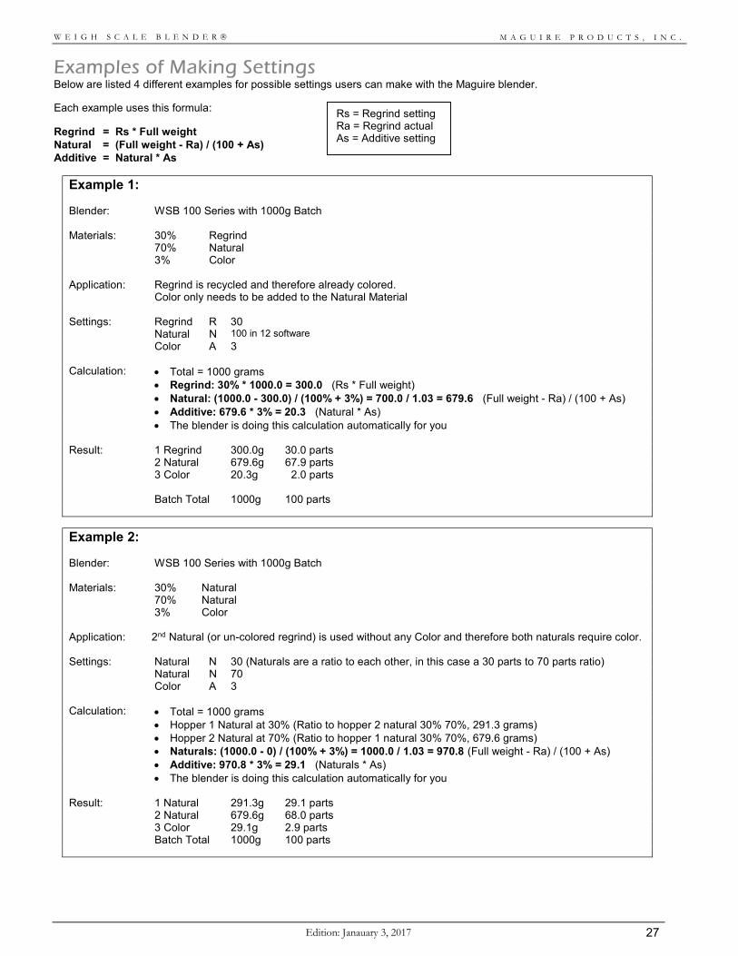
Examples of Making Settings Below are listed 4 different examples for possible settings users can make with the Maguire blender. Each example uses this formula: Regrind = Rs * Full weight Natural = (Full weight - Ra) / (100 + As) Additive = Natural * As
Example 1:
Blender: WSB 100 Series with 1000g Batch Materials: 30% Regrind 70% Natural 3% Color Application: Regrind is recycled and therefore already colored.
Color only needs to be added to the Natural Material Settings: Regrind R 30 Natural N 100 in 12 software Color A 3 Calculation: Total = 1000 grams Regrind: 30% * 1000.0 = 300.0 (Rs * Full weight) Natural: (1000.0 - 300.0) / (100% + 3%) = 700.0 / 1.03 = 679.6 (Full weight - Ra) / (100 + As) Additive: 679.6 * 3% = 20.3 (Natural * As) The blender is doing this calculation automatically for you Result: 1 Regrind 300.0g 30.0 parts 2 Natural 679.6g 67.9 parts 3 Color 20.3g 2.0 parts Batch Total 1000g 100 parts
Example 2:
Blender: WSB 100 Series with 1000g Batch Materials: 30% Natural 70% Natural 3% Color Application: 2nd Natural (or un-colored regrind) is used without any Color and therefore both naturals require color. Settings: Natural N 30 (Naturals are a ratio to each other, in this case a 30 parts to 70 parts ratio) Natural N 70 Color A 3 Calculation: Total = 1000 grams Hopper 1 Natural at 30% (Ratio to hopper 2 natural 30% 70%, 291.3 grams) Hopper 2 Natural at 70% (Ratio to hopper 1 natural 30% 70%, 679.6 grams) Naturals: (1000.0 - 0) / (100% + 3%) = 1000.0 / 1.03 = 970.8 (Full weight - Ra) / (100 + As) Additive: 970.8 * 3% = 29.1 (Naturals * As) The blender is doing this calculation automatically for you Result: 1 Natural 291.3g 29.1 parts 2 Natural 679.6g 68.0 parts 3 Color 29.1g 2.9 parts Batch Total 1000g 100 parts
Rs = Regrind setting Ra = Regrind actual As = Additive setting
M A G U I R E P R O D U C T S , I N C .
Edition: January 3, 2017 28
W E I G H S C A L E B L E N D E R
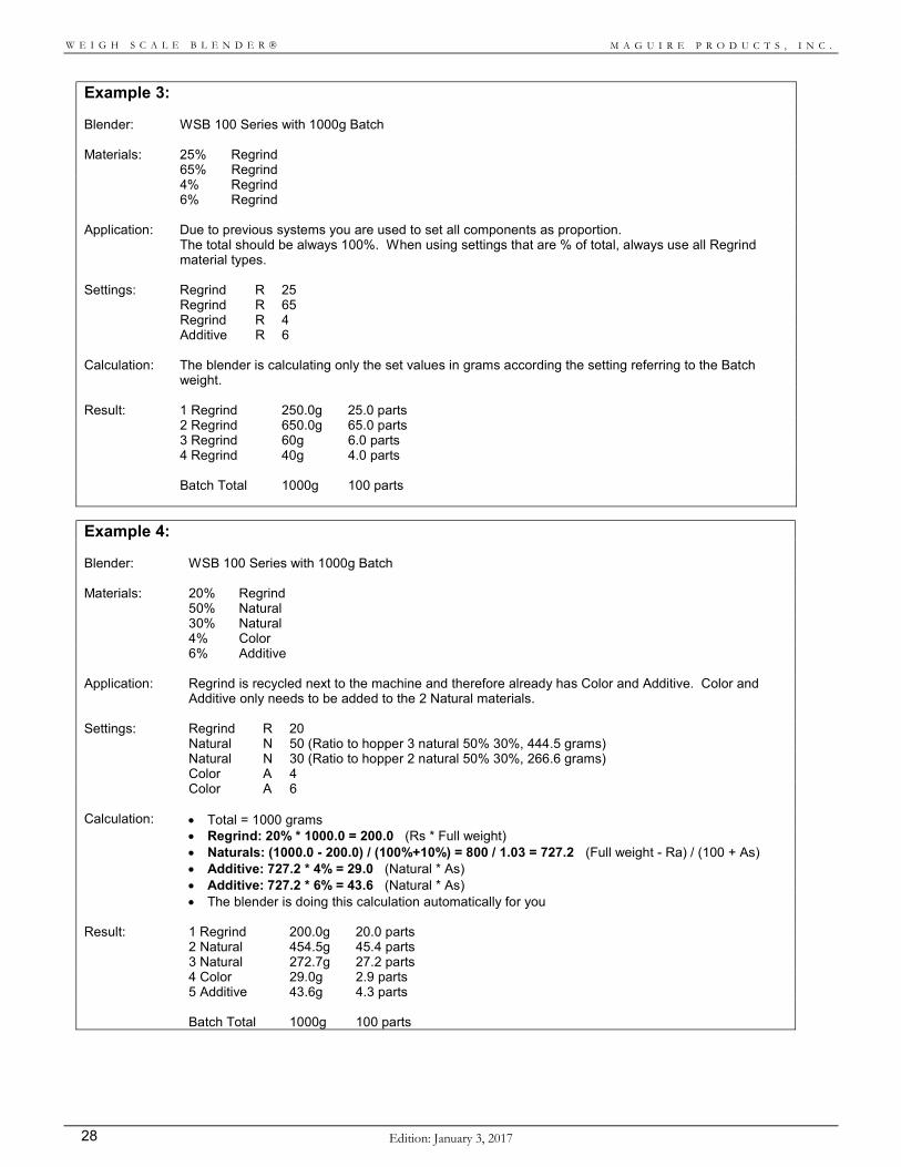
Example 3: Blender: WSB 100 Series with 1000g Batch Materials: 25% Regrind 65% Regrind 4% Regrind 6% Regrind Application: Due to previous systems you are used to set all components as proportion.
The total should be always 100%. When using settings that are % of total, always use all Regrind material types.
Settings: Regrind R 25 Regrind R 65 Regrind R 4 Additive R 6 Calculation: The blender is calculating only the set values in grams according the setting referring to the Batch
weight. Result: 1 Regrind 250.0g 25.0 parts 2 Regrind 650.0g 65.0 parts 3 Regrind 60g 6.0 parts 4 Regrind 40g 4.0 parts Batch Total 1000g 100 parts
Example 4:
Blender: WSB 100 Series with 1000g Batch Materials: 20% Regrind 50% Natural 30% Natural 4% Color 6% Additive Application: Regrind is recycled next to the machine and therefore already has Color and Additive. Color and
Additive only needs to be added to the 2 Natural materials. Settings: Regrind R 20 Natural N 50 (Ratio to hopper 3 natural 50% 30%, 444.5 grams) Natural N 30 (Ratio to hopper 2 natural 50% 30%, 266.6 grams) Color A 4 Color A 6 Calculation: Total = 1000 grams Regrind: 20% * 1000.0 = 200.0 (Rs * Full weight) Naturals: (1000.0 - 200.0) / (100%+10%) = 800 / 1.03 = 727.2 (Full weight - Ra) / (100 + As) Additive: 727.2 * 4% = 29.0 (Natural * As) Additive: 727.2 * 6% = 43.6 (Natural * As) The blender is doing this calculation automatically for you Result: 1 Regrind 200.0g 20.0 parts 2 Natural 454.5g 45.4 parts 3 Natural 272.7g 27.2 parts 4 Color 29.0g 2.9 parts 5 Additive 43.6g 4.3 parts Batch Total 1000g 100 parts
M A G U I R E P R O D U C T S , I N C .
Edition: Janauary 3, 2017 29
W E I G H S C A L E B L E N D E R
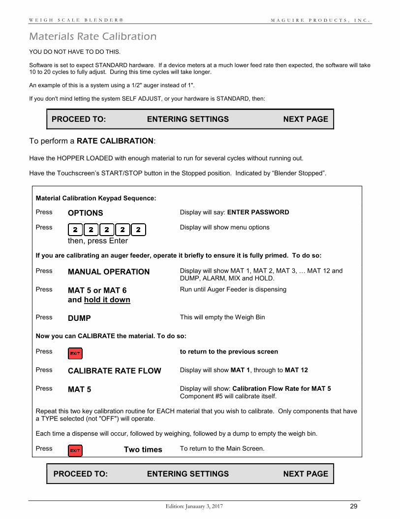
Materials Rate Calibration YOU DO NOT HAVE TO DO THIS. Software is set to expect STANDARD hardware. If a device meters at a much lower feed rate then expected, the software will take 10 to 20 cycles to fully adjust. During this time cycles will take longer. An example of this is a system using a 1/2" auger instead of 1". If you don't mind letting the system SELF ADJUST, or your hardware is STANDARD, then:
PROCEED TO: ENTERING SETTINGS NEXT PAGE
To perform a RATE CALIBRATION: Have the HOPPER LOADED with enough material to run for several cycles without running out. Have the Touchscreen’s START/STOP button in the Stopped position. Indicated by “Blender Stopped”.
Material Calibration Keypad Sequence:
Press OPTIONS Display will say: ENTER PASSWORD
Press
then, press Enter
Display will show menu options
If you are calibrating an auger feeder, operate it briefly to ensure it is fully primed. To do so: Press MANUAL OPERATION
Display will show MAT 1, MAT 2, MAT 3, … MAT 12 and DUMP, ALARM, MIX and HOLD.
Press MAT 5 or MAT 6 and hold it down
Run until Auger Feeder is dispensing
Press DUMP
This will empty the Weigh Bin
Now you can CALIBRATE the material. To do so: Press
to return to the previous screen
Press CALIBRATE RATE FLOW
Display will show MAT 1, through to MAT 12
Press MAT 5 Display will show: Calibration Flow Rate for MAT 5 Component #5 will calibrate itself.
Repeat this two key calibration routine for EACH material that you wish to calibrate. Only components that have a TYPE selected (not "OFF") will operate. Each time a dispense will occur, followed by weighing, followed by a dump to empty the weigh bin. Press
Two times To return to the Main Screen.
PROCEED TO: ENTERING SETTINGS NEXT PAGE
M A G U I R E P R O D U C T S , I N C .
Edition: January 3, 2017 30
W E I G H S C A L E B L E N D E R
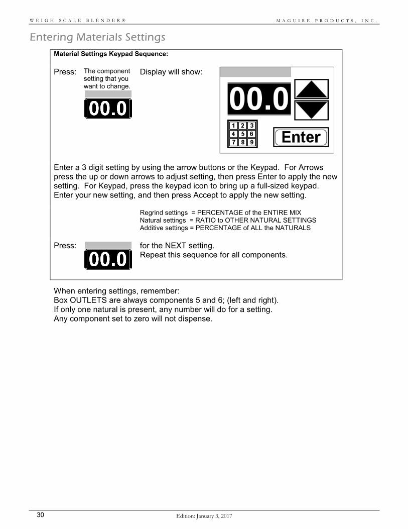
Entering Materials Settings
Material Settings Keypad Sequence:
Press: The component setting that you want to change.
Display will show:
Enter a 3 digit setting by using the arrow buttons or the Keypad. For Arrows press the up or down arrows to adjust setting, then press Enter to apply the new setting. For Keypad, press the keypad icon to bring up a full-sized keypad. Enter your new setting, and then press Accept to apply the new setting. Regrind settings = PERCENTAGE of the ENTIRE MIX
Natural settings = RATIO to OTHER NATURAL SETTINGS Additive settings = PERCENTAGE of ALL the NATURALS
Press:
for the NEXT setting. Repeat this sequence for all components.
When entering settings, remember: Box OUTLETS are always components 5 and 6; (left and right). If only one natural is present, any number will do for a setting. Any component set to zero will not dispense.
M A G U I R E P R O D U C T S , I N C .
Edition: Janauary 3, 2017 31
W E I G H S C A L E B L E N D E R
Special Instructions for Selected Models
This section relates SPECIAL information about a few selected models. MICRO PULSE
Micro Pulse valves are available on models:
WSB MB with optional VERTICAL VALVE MICRO PULSE valves. WSB 122 / WSB 140m2 with optional SLIDE GATE MICRO PULSE valves. WSB 131 / WSB 140m1 with optional SLIDE GATE MICRO PULSE valves. WSB 140Rm1 / WSB 140Rm2 with optional VERTICAL VALVE MICRO PULSE valves. WSB 240Rm1 / WSB 240Rm2 with optional VERTICAL VALVE MICRO PULSE valves. WSB 440Rm1 / WSB 440Rm2 with optional VERTICAL VALVE MICRO PULSE valves.
These models may use our "MICRO PULSE" metering system for Color and Additive components. PULSED OUTPUT parameters control the on/off timing, or pulsing, of the valves. The controlling parameters are the "PO Pulsed output / timing" component settings. When set to 00000, normal slide gate operation occurs. When set to a value, such as 00101, power will pulse ON then OFF, at 1/10 second time intervals each way. This ON/OFF cycling will repeat for the entire dispense time. When using a MICRO PULSE valve, you must set the related PO parameter to 00101. If overall blender throughput is too low, you may increase the metering rate of each Micro Pulse device by adjusting the cylinder airflow control valves for higher flow rate. This causes more rapid movement of the cylinder, ejecting more pellets per pulse. The drawback is noisy operation. We recommend air flow be adjusted for quiet operation, but assuring full valve movement per on/off cycle. We have already done this. No further adjustment should be necessary. The approximate correct airflow adjustments are:
At nose of cylinder, 1.5 full turns out from full closed. At rear of cylinder, 2.5 full turns out from full closed. MICRO BLENDER slant valves, adjust by sound.
On fixed hoppers with horizontal micro pulse valves, CLEAN OUT of the hopper can be accomplished by opening the "clean out" port provided under the valve. Turn to one side to allow material to drain. MICRO PULSE - ACCURACY All MICRO PULSE valves are more accurate if the associated PT parameter is set to 00090. Read PT parameter in the PARAMETER section. Use Options / Special Functions / Operating Options / Progressive Metering, for improved accuracy so long as the additional time necessary for Progressive Metering exists. Read about more about Progressive Metering in the Controller Functions section.
PROCEED TO: NORMAL OPERATION NEXT PAGE
M A G U I R E P R O D U C T S , I N C .
Edition: January 3, 2017 32
W E I G H S C A L E B L E N D E R
Instructions for Normal Operation
Operation is very simple.
1. Fill HOPPERS.
2. Turn POWER ON. Verify correct settings.
3. On Touchscreen Controller, press START Button. Unit will now operate automatically to maintain a level of material high enough to cover the sensor. Use the STOP Button to stop the blender (or PAUSE button for immediate pause). Turn POWER off only on final shutdown.
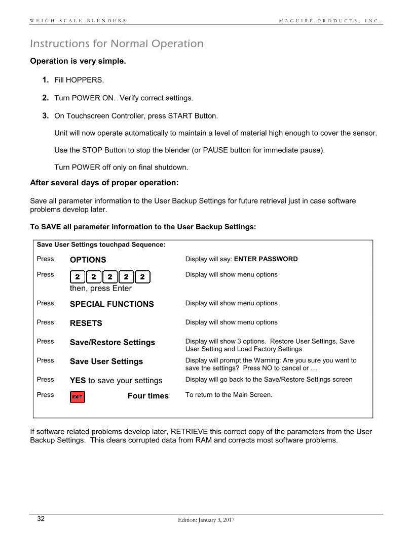
After several days of proper operation: Save all parameter information to the User Backup Settings for future retrieval just in case software problems develop later. To SAVE all parameter information to the User Backup Settings:
Save User Settings touchpad Sequence:
Press OPTIONS Display will say: ENTER PASSWORD
Press
then, press Enter
Display will show menu options
Press SPECIAL FUNCTIONS
Display will show menu options
Press RESETS
Display will show menu options
Press Save/Restore Settings
Display will show 3 options. Restore User Settings, Save User Setting and Load Factory Settings
Press Save User Settings
Display will prompt the Warning: Are you sure you want to save the settings? Press NO to cancel or …
Press YES to save your settings Display will go back to the Save/Restore Settings screen
Press
Four times To return to the Main Screen.
If software related problems develop later, RETRIEVE this correct copy of the parameters from the User Backup Settings. This clears corrupted data from RAM and corrects most software problems.
M A G U I R E P R O D U C T S , I N C .
Edition: Janauary 3, 2017 33
W E I G H S C A L E B L E N D E R
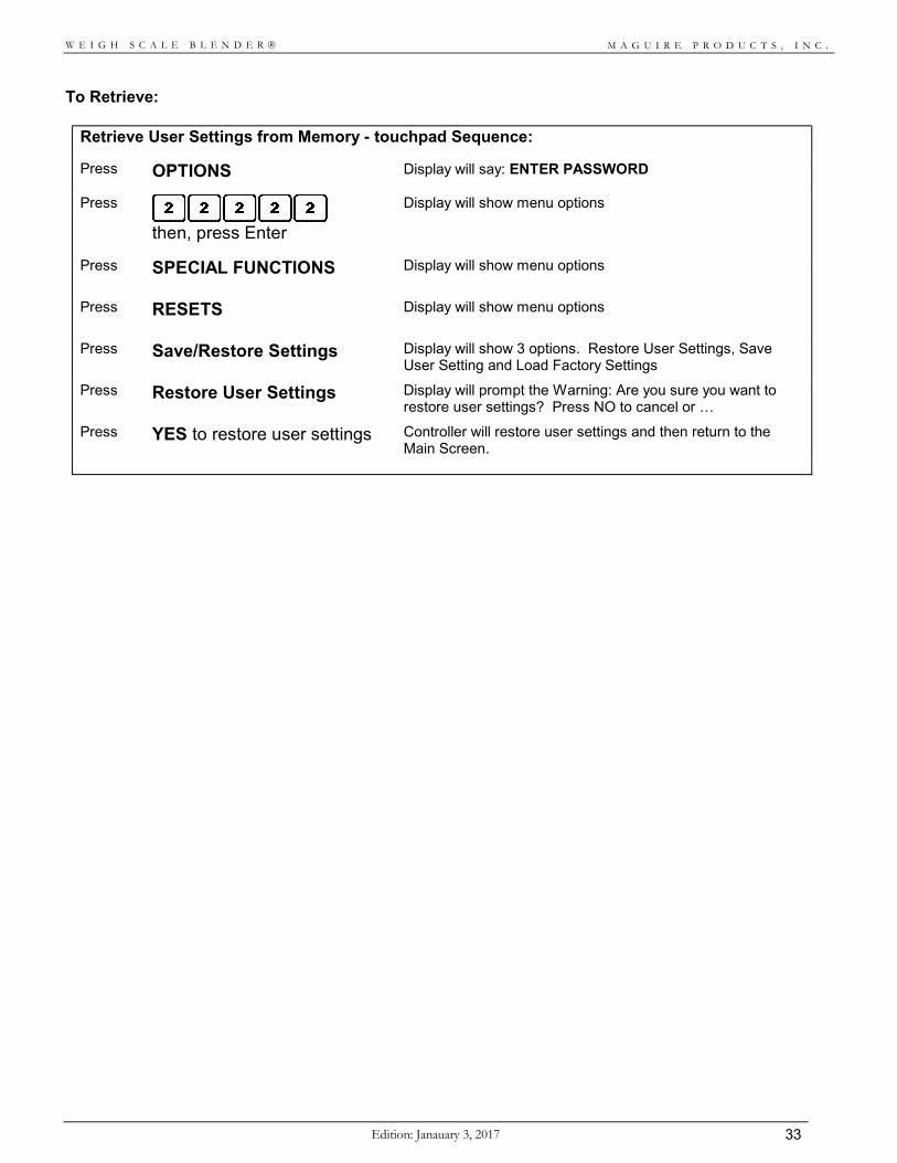
To Retrieve:
Retrieve User Settings from Memory - touchpad Sequence:
Press OPTIONS Display will say: ENTER PASSWORD
Press
then, press Enter
Display will show menu options
Press SPECIAL FUNCTIONS
Display will show menu options
Press RESETS
Display will show menu options
Press Save/Restore Settings
Display will show 3 options. Restore User Settings, Save User Setting and Load Factory Settings
Press Restore User Settings
Display will prompt the Warning: Are you sure you want to restore user settings? Press NO to cancel or …
Press YES to restore user settings Controller will restore user settings and then return to the Main Screen.
M A G U I R E P R O D U C T S , I N C .
Edition: January 3, 2017 34
W E I G H S C A L E B L E N D E R
Normal Operating Sequence - Each Cycle As the sensor is uncovered, the cycle begins. The target weight of a complete batch is 18000, 9000, 4000, 2000, 1000, or 400 grams. REGRINDS are dispensed first, in their order of size, largest dispense first. After all the Regrind dispenses, the space remaining in the weigh bin is determined. NATURALS are dispensed second, in their order of size, each at the correct ratio to the others. These dispenses are calculated to fill the bin leaving just enough space for the Additive dispenses. After all Natural dispense are complete the exact weight of all of the NATURALS is determined and, based on this actual dispense weight, the Additive dispenses are now calculated. ADDITIVES are dispensed last. These dispenses are calculated as a percentage of all the NATURAL components only. If any dispense fails to reach the requested weight, the process does NOT CONTINUE. The ALARM Strobe light flashes, the Beeper sounds, and the system continues to retry the dispense until the problem is remedied. The total batch is then dropped into the mixing chamber for blending before entering the throat of the process machine.
Special Features To use one of these SPECIAL FEATURES, read about it first. The KEYSTROKE sequence required is given at the end of this section. Function: Key: Description: TAG TAG To TAG all material usage data with Work Order or Employee numbers for better tracking of
material used.
RECIPES RECP To store RECIPES using the RECIPE storage feature.
FAST FAST To increase throughput, using the FAST key.
BATCH BTCH To blend a preset BATCH amount of material and then stop.
To display the BATCH, RECIPE, FAST, and TAG buttons these features must be enabled. Read: Enable special operations in the next section.
SETTINGS To use a lower percentage then 00.1 percent, read: PARAMETERS, _XT parameter.
MIXING To change the MIXER RUN TIME, read: PARAMETERS, MIX Parameter.
SETTINGS To place UPPER LIMITS on settings, read: PARAMETERS, _SE Parameter.
PASSWORDS To LOCK OUT others from changing the settings, read: PARAMETERS, Changing the
Password.
ACCURACY To VERIFY ACCURACY of the entire system, read: PRINTER OUTPUT and TROUBLESHOOTING sections.
DATA To TRACK MATERIAL USAGE, read: KEYPAD, VIEW DATA, and PARAMETERS, PRT Parameter.
READ the rest of the manual at your leisure to learn more about how your WEIGH SCALE BLENDER works and what else the blender can do.
M A G U I R E P R O D U C T S , I N C .
Edition: Janauary 3, 2017 35
W E I G H S C A L E B L E N D E R
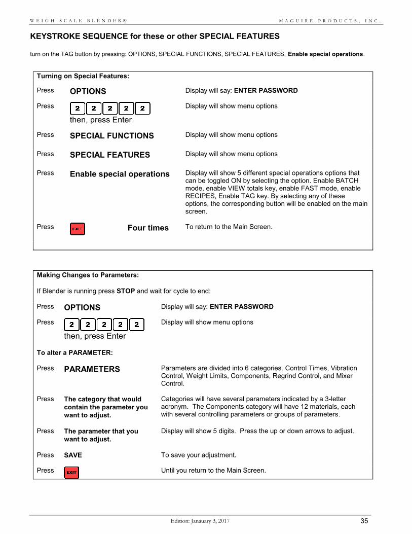
KEYSTROKE SEQUENCE for these or other SPECIAL FEATURES turn on the TAG button by pressing: OPTIONS, SPECIAL FUNCTIONS, SPECIAL FEATURES, Enable special operations.
Turning on Special Features:
Press OPTIONS Display will say: ENTER PASSWORD
Press
then, press Enter
Display will show menu options
Press SPECIAL FUNCTIONS
Display will show menu options
Press SPECIAL FEATURES
Display will show menu options
Press Enable special operations
Display will show 5 different special operations options that can be toggled ON by selecting the option. Enable BATCH mode, enable VIEW totals key, enable FAST mode, enable RECIPES, Enable TAG key. By selecting any of these options, the corresponding button will be enabled on the main screen.
Press
Four times To return to the Main Screen.
Making Changes to Parameters: If Blender is running press STOP and wait for cycle to end: Press OPTIONS Display will say: ENTER PASSWORD
Press
then, press Enter
Display will show menu options
To alter a PARAMETER: Press PARAMETERS Parameters are divided into 6 categories. Control Times, Vibration
Control, Weight Limits, Components, Regrind Control, and Mixer Control.
Press The category that would contain the parameter you want to adjust.
Categories will have several parameters indicated by a 3-letter acronym. The Components category will have 12 materials, each with several controlling parameters or groups of parameters.
Press The parameter that you want to adjust.
Display will show 5 digits. Press the up or down arrows to adjust.
Press
SAVE To save your adjustment.
Press
Until you return to the Main Screen.
M A G U I R E P R O D U C T S , I N C .
Edition: January 3, 2017 36
W E I G H S C A L E B L E N D E R
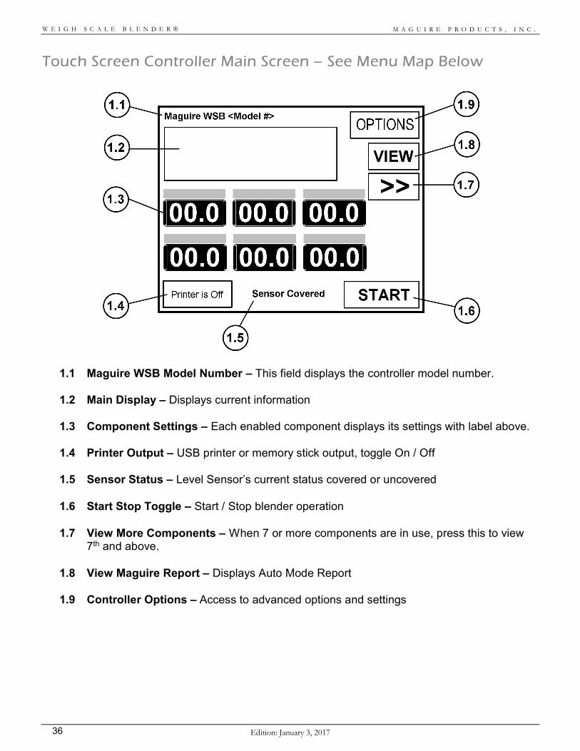
Touch Screen Controller Main Screen – See Menu Map Below
1.1 Maguire WSB Model Number – This field displays the controller model number.
1.2 Main Display – Displays current information
1.3 Component Settings – Each enabled component displays its settings with label above.
1.4 Printer Output – USB printer or memory stick output, toggle On / Off
1.5 Sensor Status – Level Sensor’s current status covered or uncovered
1.6 Start Stop Toggle – Start / Stop blender operation
1.7 View More Components – When 7 or more components are in use, press this to view 7th and above.
1.8 View Maguire Report – Displays Auto Mode Report
1.9 Controller Options – Access to advanced options and settings
M A G U I R E P R O D U C T S , I N C .
Edition: Janauary 3, 2017 37
W E I G H S C A L E B L E N D E R
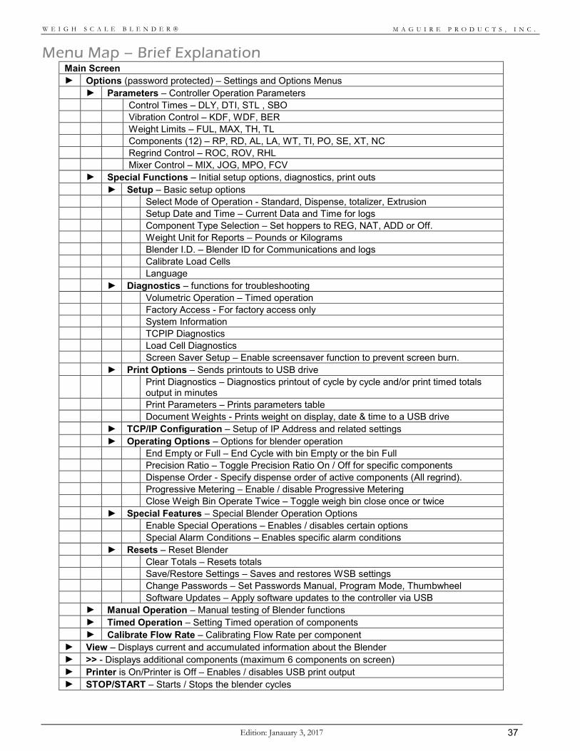
Menu Map – Brief Explanation Main Screen ► Options (password protected) – Settings and Options Menus ► Parameters – Controller Operation Parameters Control Times – DLY, DTI, STL , SBO Vibration Control – KDF, WDF, BER Weight Limits – FUL, MAX, TH, TL Components (12) – RP, RD, AL, LA, WT, TI, PO, SE, XT, NC Regrind Control – ROC, ROV, RHL Mixer Control – MIX, JOG, MPO, FCV ► Special Functions – Initial setup options, diagnostics, print outs ► Setup – Basic setup options Select Mode of Operation - Standard, Dispense, totalizer, Extrusion Setup Date and Time – Current Data and Time for logs Component Type Selection – Set hoppers to REG, NAT, ADD or Off. Weight Unit for Reports – Pounds or Kilograms Blender I.D. – Blender ID for Communications and logs Calibrate Load Cells Language ► Diagnostics – functions for troubleshooting Volumetric Operation – Timed operation Factory Access - For factory access only System Information TCPIP Diagnostics Load Cell Diagnostics Screen Saver Setup – Enable screensaver function to prevent screen burn. ► Print Options – Sends printouts to USB drive
Print Diagnostics – Diagnostics printout of cycle by cycle and/or print timed totals
output in minutes Print Parameters – Prints parameters table Document Weights - Prints weight on display, date & time to a USB drive ► TCP/IP Configuration – Setup of IP Address and related settings ► Operating Options – Options for blender operation End Empty or Full – End Cycle with bin Empty or the bin Full Precision Ratio – Toggle Precision Ratio On / Off for specific components Dispense Order - Specify dispense order of active components (All regrind). Progressive Metering – Enable / disable Progressive Metering Close Weigh Bin Operate Twice – Toggle weigh bin close once or twice ► Special Features – Special Blender Operation Options Enable Special Operations – Enables / disables certain options Special Alarm Conditions – Enables specific alarm conditions ► Resets – Reset Blender Clear Totals – Resets totals Save/Restore Settings – Saves and restores WSB settings Change Passwords – Set Passwords Manual, Program Mode, Thumbwheel Software Updates – Apply software updates to the controller via USB ► Manual Operation – Manual testing of Blender functions ► Timed Operation – Setting Timed operation of components ► Calibrate Flow Rate – Calibrating Flow Rate per component ► View – Displays current and accumulated information about the Blender ► >> - Displays additional components (maximum 6 components on screen) ► Printer is On/Printer is Off – Enables / disables USB print output ► STOP/START – Starts / Stops the blender cycles
M A G U I R E P R O D U C T S , I N C .
Edition: January 3, 2017 38
W E I G H S C A L E B L E N D E R
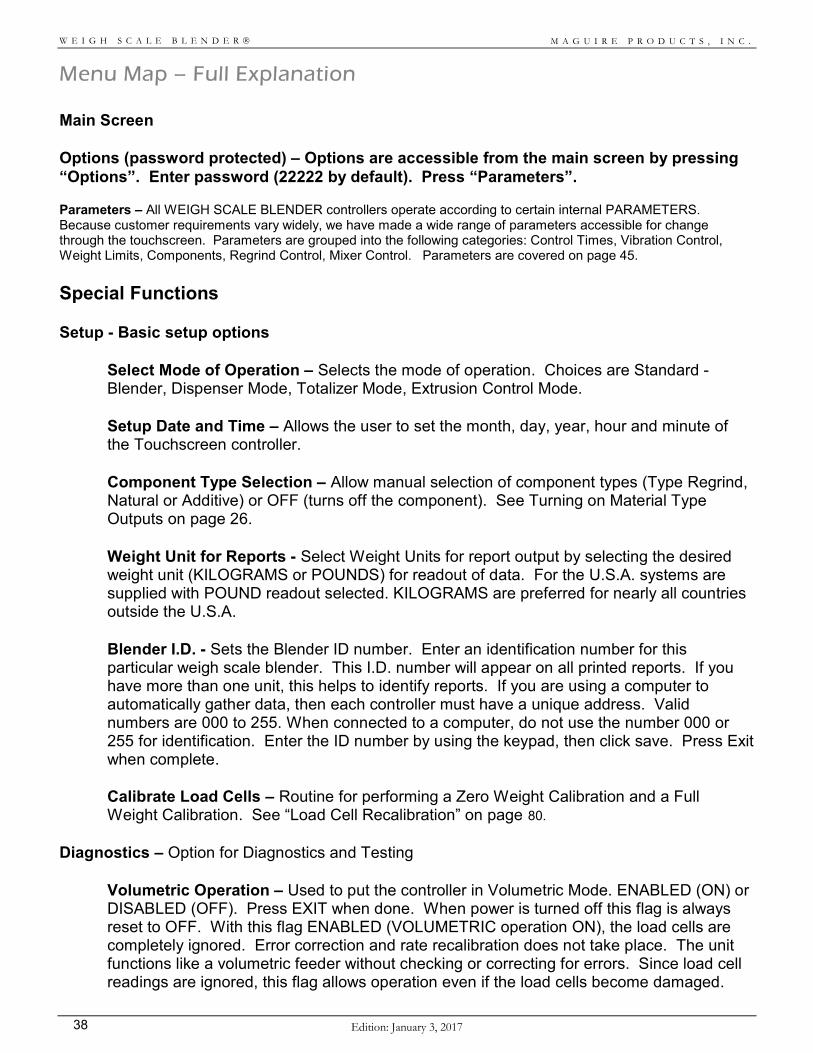
Menu Map – Full Explanation Main Screen Options (password protected) – Options are accessible from the main screen by pressing “Options”. Enter password (22222 by default). Press “Parameters”. Parameters – All WEIGH SCALE BLENDER controllers operate according to certain internal PARAMETERS. Because customer requirements vary widely, we have made a wide range of parameters accessible for change through the touchscreen. Parameters are grouped into the following categories: Control Times, Vibration Control, Weight Limits, Components, Regrind Control, Mixer Control. Parameters are covered on page 45. Special Functions Setup - Basic setup options
Select Mode of Operation – Selects the mode of operation. Choices are Standard - Blender, Dispenser Mode, Totalizer Mode, Extrusion Control Mode. Setup Date and Time – Allows the user to set the month, day, year, hour and minute of the Touchscreen controller. Component Type Selection – Allow manual selection of component types (Type Regrind, Natural or Additive) or OFF (turns off the component). See Turning on Material Type Outputs on page 26.
Weight Unit for Reports - Select Weight Units for report output by selecting the desired weight unit (KILOGRAMS or POUNDS) for readout of data. For the U.S.A. systems are supplied with POUND readout selected. KILOGRAMS are preferred for nearly all countries outside the U.S.A. Blender I.D. - Sets the Blender ID number. Enter an identification number for this particular weigh scale blender. This I.D. number will appear on all printed reports. If you have more than one unit, this helps to identify reports. If you are using a computer to automatically gather data, then each controller must have a unique address. Valid numbers are 000 to 255. When connected to a computer, do not use the number 000 or 255 for identification. Enter the ID number by using the keypad, then click save. Press Exit when complete. Calibrate Load Cells – Routine for performing a Zero Weight Calibration and a Full Weight Calibration. See “Load Cell Recalibration” on page 80.
Diagnostics – Option for Diagnostics and Testing Volumetric Operation – Used to put the controller in Volumetric Mode. ENABLED (ON) or DISABLED (OFF). Press EXIT when done. When power is turned off this flag is always reset to OFF. With this flag ENABLED (VOLUMETRIC operation ON), the load cells are completely ignored. Error correction and rate recalibration does not take place. The unit functions like a volumetric feeder without checking or correcting for errors. Since load cell readings are ignored, this flag allows operation even if the load cells become damaged.
M A G U I R E P R O D U C T S , I N C .
Edition: Janauary 3, 2017 39
W E I G H S C A L E B L E N D E R
Dispense times will be based entirely on the WT and TI parameters. Factory Access – For factory access only.
System Information – System Information displays the following information: Software version, serial number, build version, power board firmware version, WSB model, IO Type, Config version, last loaded software version, time and date, WSB ID#, IP address, subnet mask, TCP port, WTD. TCPIP Diagnostics – TCP diagnostics provides an array of Ethernet diagnostics information. Load Cell Diagnostics – Load cell diagnostics provides raw feedback from the load cells. Screen Saver Setup – Screen saver setup allows a screen saver to be enabled/disabled and a time for the screen saver to be activated. When enabled, the screen saver will only activate if the time selected elapses after no user feedback and when the controller is displaying the main screen. During an active screen saver, the moving display will show the actual weight.
Print Options – Used for Printouts Print Diagnostics – Cycle-by-Cycle Printout. Select “Print Diagnostics” to set flag for a printout of data after each full dispense cycle. With this flag ENABLED and with a USB Flash Drive in the USB port, four lines of information about the dispense cycle that just occurred will be sent to the printer. Press “Print Diagnostics” to toggle between ENABLED (Bullet ON) and DISABLED (Bullet OFF). A file will be created on the USB drive called print.txt. The information in this file includes dispense weight and percentage of each component, the internal rate numbers used by the computer to determine dispense time, and the actual dispense time of each component. This is excellent information to track the accuracy of each dispense cycle and the accuracy of the entire system over an extended period of time. Select “Print material totals every 2 minutes” to add material totals to the file. Print Parameters – Parameter Printout. Press “PRINT” to print a file called parameters.txt to a USB Flash drive. This file will contain all internal parameters. A USB flash drive must be plugged into the USB drive. Up to 13 lists will print, a General list and 12 component lists. Only components that are turned "on" will print. A Summary of the Blender will print followed by five columns, the parameter name, Factory, User, Saved and Current. Also printed is Model, software version, Special Features (on or off), Functions (on or off), Progressive metering state and device, as well as _PT percent. Document Weights – Press “Print” force a printout of the displayed weight on the controller. A USB flash drive must be plugged into the USB drive. DATE, TIME, Machine number, and display will print: Date: 11/09/2008 Time: 17:22:01 Machine number: 002 Display Readout: 500.0
M A G U I R E P R O D U C T S , I N C .
Edition: January 3, 2017 40
W E I G H S C A L E B L E N D E R
This is useful for obtaining printed verification of load cell accuracy for ISO and other international quality program rules. The recommended procedure is: 1. Place the unit into the Program mode (press OPTIONS). 2. Press Special Functions, Print Options, Document Weight, then press the “Print”
button for printout of empty bin TARE weight. 3. Place a KNOWN CERTIFIED WEIGHT into the weight bin. 4. Press “Print” again for printout with the weight added. 5. The different between the two weight printouts should equal the KNOWN
CERTIFIED WEIGHT.
TCP/IP Configuration – Configure controller IP Address, Subnet, Default Gateway, Remote IP, Local Port and Host Port. Communications are used specifically for MLAN (Maguire Local Area Network) Protocol communications. For more, see Communications on page 23. Operating Options – Special Operating Options
End Empty or Full - END the Cycle with: BIN EMPTY (standard), or BIN FULL This flag for SPECIAL APPLICATIONS ONLY. Select Standard: end with bin empty or select Option: end with bin full to tell the controller to end a cycle when the weigh bin is EMPTY or end with the bin FULL. The BIN FULL option is only for special installations where the sensor has been relocated BELOW the mix chamber and the instructions to do otherwise. Precision Ratio – Precision Ratioing for Additives Select this option to produce a precision ratioing of a selected Additive. Press the displayed Component (MAT 3, MAT 4, etc) to toggle between PRECISION RATIOING OFF, PRECISION RATIO Material 1 ON, PRECISION RATIO Material 2 ON, etc. Only those components already designated as an ADDITIVE will be displayed. If precision rationing is selected, the specified additive will dispense BEFORE the Naturals, instead of after. Natural dispenses occur after the selected additive dispense and are calculated to assure the most exact percentage ratio for the selected component. Because the Natural dispenses are larger, this method allows for more exact ratioing of the one selected critical component. Dispense Order - For recipes containing all regrind type components. Specify the dispense order of active regrind components. Select the components by selecting them in the order that they should be dispensed. Dispense order will display above. Clear will remove dispense order. New recipes will inherit dispense order. Internally saved recipes will save the dispense order. Progressive Metering – Progressive Metering allows for more accurate dispenses of selected components. However, cycle time will be extended by a few additional seconds. In normal operation blenders target a dispense of the full requested amount in one try. This almost always works, and generally will fall within acceptable upper and lower error limits. Making the dispense in one try allows for high throughput rates while still achieving a level of accuracy acceptable for most processors. When the accuracy of one particular component is critical, or the process depends on maintaining a tighter tolerance of this
M A G U I R E P R O D U C T S , I N C .
Edition: Janauary 3, 2017 41
W E I G H S C A L E B L E N D E R
component, customers may lengthen the blend cycle time slightly to achieve this higher level of accuracy. The Progressive Metering function is used to turn on this function for a selected component. This sets parameters which will cause the dispense to occur in several progressively smaller dispenses. This results in a more accurate dispense. The first dispense targets only 85 percent (the default percentage) of the full required amount. After careful weighing, each successive dispense targets 50 percent of the remaining shortage. This continues until the amount reaches, or is within 1 percent of, the target. In this manner the software "sneaks up" on the target, providing the maximum achievable accuracy possible. When Progressive Metering is Enabled, then a component is selected and Enabled, the corresponding PT and RP parameters are set to PT 00085 and RP 00001.
The Touchscreen Sequence: Press Progressive Metering (Special Functions, Operating Options, Progressive Metering). Display will show up to 12 components labeled MAT 1, MAT 2, etc. Display will also show a radio button to select (Enable) or deselect (disable) Progressive Metering. Press this radio button to Enable System Progressive Metering. Select the component that you want to enable for Progressive Metering. The Display will show Device 01 (or Device 02, etc) and the First Try % adjustable with the arrow buttons. Also shown will be a radio button to select (Enable) or deselect (disable) Progressive Metering for this component. Press this radio button to Enable System Progressive Metering. You may change the 85 by entering a different number using the arrow keys. Too low a setting will just add time. Too high will cause occasional overshooting.
Press EXIT when done to save new settings.
Close Weigh Bin Operate Twice – Weigh Bin Double Dump Select Optional: Operate Twice option to cause the weigh bin dump valve to operate two times. We call this a "double dump". If you have problems with material hanging up in the weigh pan, this may help shake it loose. Select Optional to operate Dump the dump valve twice. Select Standard to operate the Dump valve once. Press EXIT when done.
Special Features
Enable Special Operations Enable BATCH Mode - This option allows you to blend a PRE-SELECTED WEIGHT of material, and then STOP running and sound the ALARM. The process may also be programmed to sound the alarm but continue running. Since each cycle will always blend a full weigh bin amount, the total amount blended may exceed the target batch weight by up to one cycle's blend weight. When Enabled a new button labeled BTCH will appear on the Main display Screen of the controller. The ALARM SILENCE button on the display is the ONLY way to CONTINUE OPERATION after a BATCH amount has been run. Assuming BATCH Mode is enabled: Press the BTCH key once to view the desired BATCH WEIGHT.
M A G U I R E P R O D U C T S , I N C .
Edition: January 3, 2017 42
W E I G H S C A L E B L E N D E R
Display will say: BATCH Weight (lbs) BATCH WEIGHT is the amount you wish to dispense before stopping and/or sounding the alarm. CURRENT PORTION, of the batch, that has been dispensed. CURRENT PORTION also shows how much of the Batch Weight you have blended so far. Accum. Total (ACCUMULATED TOTAL) is the sum weight of all batches that have been blended. This number will continue to grow until it is manually cleared to zero, or it exceeds its maximum possible value. BATCH COUNT is the total number of batches that have run. This number will continue to grow until it is manually cleared to zero, or it exceeds its maximum possible value. Press Save after any changes have been made. Press EXIT to return to normal operation. When displaying any of the above totals, you may press the Clear to RESET that number to zero. While all four totals can be cleared to zero manually, only the BATCH WEIGHT number can be entered manually. When the BATCH WEIGHT is being displayed, you may enter a NEW batch weight using the keypad. Maximum value in lbs that can be entered is "5999.9". The unit of weight that will be used is either POUNDS or KILOGRAMS as determined by the Weight Units for Reports in Setup. While in operation, when the total is reached, the system will alarm and stop blending if Batch Mode is Enabled. The system will alarm but CONTINUE if this option is enabled. Use the ALARM SILENCE button to silence the alarm. Pressing the BTCH key to view the information will also silence the alarm. If the system is programmed to STOP at the end of a batch, the ALARM SILENCE button MUST be pressed to start blending the next batch. The First press of the ALARM SILENCE button will silence the alarm. The Second press will start the next batch. VIEW TOTALS KEY – Enable this feature to display a main screen button that will show the following data when pressed: The CURRENT Date and Time, LAST CLEARED date and time, Total number of CYCLES that have occurred, and stored material usage data (only active components are displayed). Material totals are available: (in Pounds, Kilos, Grams, or Ounces) Below the report are three buttons: PRINT (Prints to the USB Flash Drive), Clear (Clears totals in the report, NOTE; Clearing totals will effect the Get Totals command if using Ethernet Communications). EXIT will exit out of the View screen.
FAST Mode (FAST CYCLES) – When enabled a button labeled FAST will display on the controller main screen. FAST will allow you to exceed the normal blending rate of your unit. Once your system has learned proper flow rates of each material, the timing of each component dispense is very consistent cycle to cycle. The FAST key allows one or more FAST REPEAT cycles to follow a normal calibrated cycle. In a FAST REPEAT cycle all components are dispensed simultaneously, without any weights being taken. Errors in dispense amounts will not be detected. These are, in fact, volumetric dispenses, not gravimetric. These dispenses take much less time. Throughput is easily doubled in this manner. The shorter mixing time may be a problem. So the number of FAST REPEAT cycles is kept as low as possible. Up to 4 repeats may occur. When enabled (selected) every normal calibrated dispense will be followed by up to 4 FAST repeat dispenses. This series of 4 dispenses is terminated as soon as the sensor is covered, which indicates the blender has "caught up". The next cycle will then be a weighed cycle, followed by the required series of fast cycles to catch up again. When the FAST mode is in operation, the display will flash “FAST” intermittently. RECIPES – When enabled a button labeled RECP will display on the controller main screen. This button allows you to GET, LOAD, and SAVE RECIPES. To SAVE a recipe, enter a recipe number between 1 and 99, then press ENTER. This saves the current settings loaded in the controller under this recipe number. 99 recipes may be stored, numbered 1 to 99. Press CLEAR to clear the current recipe number (currently loaded settings remain loaded). If no RECIPE is currently in use, display says shows current recipe as 0.
M A G U I R E P R O D U C T S , I N C .
Edition: Janauary 3, 2017 43
W E I G H S C A L E B L E N D E R
Enter 2 digits to retrieve one of 50 recipes. Display will flash through this recipe data: (RCP 01), (1R= xx ), (2N= xx.x), etc., (* = LOAD) Press "*" to LOAD this recipe into memory. Routine will exit automatically. Press RCP or EXIT to return to the display (GET --). Press RCP or EXIT again to exit. To SAVE a RECIPE you must be in the PROGRAM mode. If you press RCP key again after display of (GET --), display says (SAVE --). Enter 2 digits, display will say (SAVING ). The current settings are saved into memory under the recipe number you have entered. Routine will EXIT automatically.
EXIT will exit at any time. To clear a recipe, set all component settings to zero and save these settings into the recipe location. TAG - This key allows two pieces of information to be "tagged" onto all data that is either printed or retrieved through the computer communications ports. The items are WORK ORDER number and OPERATOR number. This key is NOT FUNCTIONAL unless the 2nd digit of the "FLG" parameter is set to 1 (x1xxx). To do this, see the SOFTWARE MAINTENANCE section, PARAMETER TABLE, "FLG". Press once to display the current Work Order number: Work Order: xxxxxx. Press again to display the current Operator number: Operator Number: xxx. Press again for the Recipe number: Recipe: xxxxx. You may enter or change the Work Order or Operator number, when each is displayed to tag all information with these numbers. The Recipe number is used only for the Recipe Auto Download feature of the G2 software or the earlier MLAN software. For information on Auto-download see the Recipe Auto Download function in the G2 Software Manual. Work Order and Operator numbers are for your TRACKING of information ONLY. They have NO EFFECT on the operation of the Weigh Scale Blender.
WORK ORDER number (6 digits) allows you to tag all information with an internal accounting number such as a job or purchase order number. To set a work order, enter a number ranging from 1 to 999999, then press SAVE.
OPERATOR number (3 digits) allows you to track who is operating the equipment. To set an operator
number, enter a number ranging from 1 to 999, then press SAVE.
RECIPE number allows you to request a recipe stored in the G2 Software using a recipe number between 100 and 65536. The Recipe Tag number is not for loading internally stored recipes. See the RECIPE key for loading internally stored recipe numbers. If a recipe has been entered using our G2 or MLAN software, then a 3-digit or 5-digit number will be displayed in this field. If a new recipe number is entered and the TAG or EXIT key is pressed, the controller will display: Waiting for Recipe… At this time, the controller is requesting a recipe from the G2 Software using the MLAN protocol. A matching recipe number found in the G2 Recipe database will then be sent to the controller, enabling or disabling components and setting settings. G2 will then begin tracking material usage for that recipe. If the G2 Software does not have a matching recipe number, the controller will alarm briefly and then revert back to it’s previous loaded recipe. A successfully loaded recipe number will be displayed and "tagged" to all printouts and retrievals. EXIT will exit the sequence at any point. Exit will also abort a pending Recipe Auto Download.
Special Alarm Conditions Enable Alarms Weigh bin loosing weight – When enabled, if the weigh bin weight drops more them 20 grams during a cycle this alarm will sound. This serves to detect and report a weigh bin problem, such as material leaking from the bottom of the bin.
M A G U I R E P R O D U C T S , I N C .
Edition: January 3, 2017 44
W E I G H S C A L E B L E N D E R
Maximum weight exceeded – When enabled, if the MAX (parameter) weight is exceeded, the system will stop and the Alarm will sound. This might occur if a valve sticks open or slightly open. Normally the system recovers automatically from such events with only the one batch blended incorrectly. Set the flag only if you want the system to stop and alarm. Batch complete (Batch Mode) – When enabled, the alarm will sound when the batch weight is complete. See page 41 for details on Batch Mode. Enable mix motor failure alarm – When enabled and used with the Mix Motor Failure Kit (KIT-075T), this alarm will sound when the mix motor fails to move during intended operation. Cycle time out: When enabled, this alarm will sound when the MCT parameter is activated. When MCT is used, it monitors sequential cycle times, and alarms (when alarm is enabled) if a cycle time exceeds the previous cycle time by an amount that is not consistent with proper operation. This provides a means to detect mechanical failures such as a sticking valve or weigh bin gate. For more information, see MCT the parameter on page 60.
Resets
Clear Totals – Pressing Clear Totals will reset all component totals back to zero. Component totals are visible from the main screen by pressing the View button. Component totals are also visible through MLAN communications. Save/Restore Settings – Used for saving or restoring previously saved parameters. For more information on Saving and Restoring Settings, see “Saving Parameters in the User Backup Settings” on page 63. Change Passwords – Used to set access passwords for Manual Mode, Program Mode and Thumbwheel Unlock. Default passwords are: 11111 for Manual Mode, 22222 for Program Mode and 14789 for Thumbwheel unlock. Software Update – Software Updates to Touchscreen Controller. See “Updating Controller Firmware” on page 80.
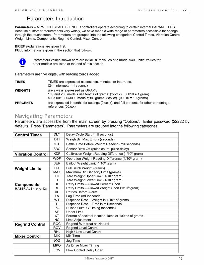
M A G U I R E P R O D U C T S , I N C .
Edition: Janauary 3, 2017 45
W E I G H S C A L E B L E N D E R
Parameters Introduction Parameters – All WEIGH SCALE BLENDER controllers operate according to certain internal PARAMETERS. Because customer requirements vary widely, we have made a wide range of parameters accessible for change through the touchscreen. Parameters are grouped into the following categories: Control Times, Vibration Control, Weight Limits, Components, Regrind Control, Mixer Control. BRIEF explanations are given first. FULL information is given in the section that follows.
Parameters values shown here are initial ROM values of a model 940. Initial values for other models are listed at the end of this section.
Parameters are five digits, with leading zeros added.
TIMES TIMES are expressed as seconds, minutes, or interrupts. (244 interrupts = 1 second).
WEIGHTS are always expressed as GRAMS. 100 and 200 models use tenths of grams: (xxxx.x). (00010 = 1 gram) 400/900/1800/3000 models; full grams: (xxxxx). (00010 = 10 grams)
PERCENTS are expressed in tenths for settings (0xxx.x), and full percents for other percentage references (00xxx).
Navigating Parameters Parameters are accessible from the main screen by pressing “Options”. Enter password (22222 by default). Press “Parameters”. Parameters are grouped into the following categories:
Control Times DLY Delay Cycle Start (milliseconds)
DTI Weigh Bin Max Empty (seconds)
STL Settle Time Before Weight Reading (milliseconds)
SBO Sensor Blow Off (pulse count, pulse delay)
Vibration Control KDF Calibration Weight Reading Difference (1/10th gram)
WDF Operation Weight Reading Difference (1/10th gram)
BER Bailout Weight Limit (1/10th gram)
Weight Limits FUL Full Batch Weight (grams) MAX Maximum Bin Capacity Limit (grams) TH Tare Weight Upper Limit (1/10th gram) TL Tare Weight Lower Limit (1/10th gram)
Components MATERIALS 1 thru 12:
RP Retry Limits – Allowed Percent Short RD Retry Limits – Allowed Weight Short (1/10th gram) AL Retries Before Alarm LA Lag Time (milliseconds) WT Dispense Rate – Weight in 1/10th of grams TI Dispense Rate – Time in milliseconds
PO Pulsed Output / Timing (seconds) SE Upper Limit XT Format of decimal location 10ths or 100ths of grams NC Limit Adjustment
Regrind Control ROC Regrind % to treat as Natural ROV Regrind Level Control RHL High / Low Level Control
Mixer Control MIX Mix Time
JOG Jog Time
MPO Air Drive Mixer Timing
FCV Flow Control Delay Open
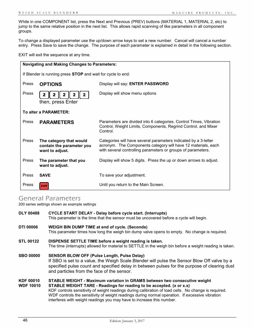
M A G U I R E P R O D U C T S , I N C .
Edition: January 3, 2017 46
W E I G H S C A L E B L E N D E R
While in one COMPONENT list, press the Next and Previous (PREV) buttons (MATERIAL 1, MATERIAL 2, etc) to jump to the same relative position in the next list. This allows rapid scanning of like parameters in all component groups. To change a displayed parameter use the up/down arrow keys to set a new number. Cancel will cancel a number entry. Press Save to save the change. The purpose of each parameter is explained in detail in the following section. EXIT will exit the sequence at any time.
Navigating and Making Changes to Parameters: If Blender is running press STOP and wait for cycle to end: Press OPTIONS Display will say: ENTER PASSWORD
Press
then, press Enter
Display will show menu options
To alter a PARAMETER: Press PARAMETERS Parameters are divided into 6 categories. Control Times, Vibration
Control, Weight Limits, Components, Regrind Control, and Mixer Control.
Press The category that would contain the parameter you want to adjust.
Categories will have several parameters indicated by a 3-letter acronym. The Components category will have 12 materials, each with several controlling parameters or groups of parameters.
Press The parameter that you want to adjust.
Display will show 5 digits. Press the up or down arrows to adjust.
Press
SAVE To save your adjustment.
Press
Until you return to the Main Screen.
General Parameters 200 series settings shown as example settings DLY 00488 CYCLE START DELAY - Delay before cycle start. (Interrupts)
This parameter is the time that the sensor must be uncovered before a cycle will begin. DTI 00006 WEIGH BIN DUMP TIME at end of cycle. (Seconds)
This parameter times how long the weigh bin dump valve opens to empty. No change is required. STL 00122 DISPENSE SETTLE TIME before a weight reading is taken.
The time (interrupts) allowed for material to SETTLE in the weigh bin before a weight reading is taken.
SBO 00000 SENSOR BLOW OFF (Pulse Length, Pulse Delay) If SBO is set to a value, the Weigh Scale Blender will pulse the Sensor Blow Off valve by a specified pulse count and specified delay in between pulses for the purpose of clearing dust and particles from the face of the sensor. KDF 00010 STABLE WEIGHT - Maximum variation in GRAMS between two consecutive weight WDF 10010 STABLE WEIGHT TARE - Readings for reading to be accepted. (x or x.x)
KDF controls sensitivity of weight readings during calibration of load cells. No change is required. WDF controls the sensitivity of weight readings during normal operation. If excessive vibration interferes with weight readings you may have to increase this number.
M A G U I R E P R O D U C T S , I N C .
Edition: Janauary 3, 2017 47
W E I G H S C A L E B L E N D E R
BER 01000 BAIL-OUT THRESHOLD - Excess GRAM weight before dispense is aborted. This parameter controls sensitivity of the emergency "bailout" routine that prevents overfilling of the weigh bin. No change is required.
FUL 20000 FULL BIN WEIGHT - determined by weigh bin size. MAX 30000 Maximum BIN WEIGHT - weight the software will target (grams).
FUL is the target weight that is blended each cycle. Change only for extremely fluffy or very heavy material. MAX prevents overflowing of the weigh bin. It is reset automatically if the FUL parameter is changed.
TH 01000 VALID TARE WEIGHT HIGH - The highest acceptable TARE weights for Blend cycle to start. TL 00500 VALID TARE WEIGHT LOW - The lowest acceptable TARE weights for Blend cycle to start.
TL prevents starting with the weigh bin out of place. No change is required. TH prevents starting with a full weigh bin. Change TH only if clumps of material hang up in the weigh bin.
ROC 00000 REGRIND OVERCOLOR - ROC, ROV, and RHL help control regrind usage.
ROC indicates the PERCENT of REGRIND that will be treated as natural when COLOR and ADDITIVE dispenses are calculated. This adds some color or additive to your regrind.
ROV 00000 REGRIND OVERRIDE - ROV is for closed loop fully automatic reprocessing of regrind scrap. This parameter will detect when more regrind is being produced than consumed, and override the current setting to use a higher amount. This helps prevent material backing up in your grinder.
RHL 00000 REGRIND LEVELS – HI/LOW - RHL has effect only if level sensors are added to your unit to detect material level in the regrind hopper. These level sensors can alter regrind percent usage.
MIX 00015 MIXER MOTOR TIME
This parameter times how long the MIX motor runs.
JOG 03030 MIXER MOTOR JOGGING, COUNTS and TIME JOG indicates the number of times the blade will jog after initial mixing is ended, plus the time interval between these jogs.
MPO 00000 For air drive reciprocating mix motor FCV 00006 FLOW CONTROL DELAY - TIME the Flow Control valve delays before opening (Seconds).
This parameter holds each batch in the mix chamber for a time to assure mixing. This is only for units equipped with the optional flow control valve under the mix chamber.
PRT 00000 REPORT INTERVAL - MINUTE interval between automatic print of TOTALS.
This parameter will cause your system to PRINT MATERIAL TOTALS automatically. A USB Flash Drive must be connected. This parameter is located under Options / Special Functions / Print Options / Print Diagnostics.
M A G U I R E P R O D U C T S , I N C .
Edition: January 3, 2017 48
W E I G H S C A L E B L E N D E R
Component Parameters There are 12 Groups of 10 parameters each. The first digit is the component number. Component 1 is shown here. There are 11 more just like it. 1RP 00010 PERCENT shortage error that will force a retry. 1RD 00300 GRAM weight shortage error that will force a retry.
Retries occur until both conditions are met. 1AL 00000 Last digit = number of retries before ALARM.
00001 to 00009 = sound alarm, hold process. 00011 to 00019 = sound alarm, continue process.
These parameters set ALARM functions. When material runs out, or does not dispense fully, these flags instruct the controller what to do. Default settings shown are for Natural, Color, and Additive to alarm, but not Regrind.
1LA 00020 Lag TIME before dispense ACTUALLY starts.
(mechanical response time, interrupts) These parameters state the lag time between when a device is signaled and when it actually begins to operate. Change ONLY if you change to non-standard equipment.
1WT 24000 WT/TI = the rate that will be used for calculating the next dispense time. 1TI 01952
WT = the Weight portion of the dispense rate, calculated such that WT/TI equals the average of the last two actual dispense rates. TI = the TIME portion of the dispense rate. (Interrupts) These change AUTOMATICALLY during normal operation. They are Weight and Time portions of the flow rate calibration.
1PO 00000 Pulse rate of "MICRO PULSE" valves. 1SE 01000 Upper SETTING limits for thumbwheels (0xxx.x).
Settings greater than limit are held to limit. (01000) = 100%
These parameters can SET UPPER LIMITS to the thumbwheels. For color and additive, lower settings may help ensure expensive material is not wasted.
1XT 00000 Move decimal left on color and additive settings.
These parameters allow entry of less then (00.1) percent for COLOR or ADDITIVE. When set to "00010" settings are read as X.XX percent. When set to "00100" settings are read as .XXX percent.
1NC 00001 Allowable GRAM error within which NO correction is made.
This is the acceptable error range for each component to prevent hunting. They adjust automatically over an extended time period to match the flow characteristics of each material.
M A G U I R E P R O D U C T S , I N C .
Edition: Janauary 3, 2017 49
W E I G H S C A L E B L E N D E R
Parameter List – Full Explanations Parameters – Parameters are grouped into the following categories: Control Times, Vibration Control, Weight Limits, Components, Regrind Control, Mixer Control. Control Times
DLY Consider changing if mixing is a problem
DLY is the TIME the mix chamber level sensor must be uncovered before a cycle begins. The sensor must be uncovered without interruption for the full specified DELAY time. To prevent false starts from material movement caused by the mix blade, a minimum of 2 seconds (00488) is recommended.
Sometimes throughput is slow enough that each new batch buries the mix blade for a while. When this happens the material on top does not mix well. To reduce this, you can delay the start of a new batch by increasing the DLY parameter. The new batch is delayed and mix chamber level has time to fall before the next batch is added.
DTI Probably no need to ever change this
DTI is the maximum TIME allowed for the weighing bin to dump at the end of the cycle. The software will close the bin earlier if it detects no weight change occurring. This time determines the maximum time that is allowed for the bin to empty. We set this maximum time limit according to the model and batch size.
STL No change required
STL is the TIME period allowed to pass after a dispense has occurred, but before a weight reading is taken. This settle time allows falling pellets to reach the bin and also prevents their impact with the bin from adding to the weight reading.
SBO - Sensor Blow Off If SBO is set to a value, the Weigh Scale Blender will pulse the FCV valve by a specified pulse length and specified delay in between pulses for the purpose of clearing dust and particles from the face of the sensor. This is a 5-digit parameter. The first digit (X0000) sets how many times the blow off will pulse every cycle. Example: 1=10, 2=20, 3=30 etc. The second and third digits sets the off time in seconds. The fourth and fifth digits sets the on time in milliseconds. If needed, the recommended SBO parameter setting is 23002, which would set a blow off every 30 seconds for 200 milliseconds up to 20 times as long as the sensor is covered. You can adjust the last digit to increase or decrease the pulse.
Vibration Control
KDF Typically No change required - Change only if you have an extreme vibration problem WDF KDF and WDF are the maximum acceptable variation in GRAMS between two consecutive
weight readings. One weight reading requires 1 second of time. Two readings are always taken and they must be within KDF grams of each other to be accepted as valid. Readings are taken continuously until two consecutive readings meet the criteria. This prevents a single accidental bump of the scale from causing a grossly inaccurate reading. WDF also allows the first digit to determine how long a reading is taken. A 1 in the first position indicates ½ second per reading. 2 means 1 second, 3 means 1.5 seconds, up to 5, which is 2.5 seconds. The higher this number the slower the blend rate, but the more reliable the readings.
M A G U I R E P R O D U C T S , I N C .
Edition: January 3, 2017 50
W E I G H S C A L E B L E N D E R
KDF is used for load cell calibration weights, WDF for starting tare weight and component dispense weights.
BER Change only if severe vibration causes problems
BER is the BAILOUT ERROR weight. Dispenses are controlled by very accurate timing. However, as a precaution, the weigh bin is constantly monitored during each dispense. If bin weight is found to exceed target weight during the dispense, then a BAILOUT occurs. This ends the dispense immediately just as if the end of the dispense time period had been reached. This in no way affects the accuracy of the remainder of the cycle. The dispense is checked and retries will occur if required.
A bailout does not occur unless target weight is exceeded by the weight given in the BAILOUT ERROR parameter. This is primarily to prevent vibration from causing a false bailout during very small dispenses. We set this parameter to a default of 00200 (20 grams or 200 grams). If vibration is causing false bailouts, then you may want to set a higher value in this parameter.
If the BER parameter has a 1 in the last position, (BER 00201), then a printout will occur of all cycle data anytime a bailout occurs for any single component. This is helpful if you want to be aware of occurrences where dispenses significantly exceed target. This will be the same information that you see when the PRINT flag is on (*54). A printer must be connected.
Weight Limits
FUL Change only for extremely fluffy or heavy material
FUL is the full batch weight in GRAMS set at the factory to 1000, 2000, 4000, 9000, or 18000 grams, depending on model. The criteria for this number is to not exceed the volume capacity of the weigh bin and to not exceed the load cell capacity. On a 9000 gram system, load cells are rated for 10,000 grams each. Total load capacity is 20,000 grams. The weigh bin, when empty, weighs about 2400 grams, leaving a net capacity of 17,600 grams for weighing material. However, a dispense over 13,000 grams probably would exceed the volume capacity of the bin. We have set the full batch weight to 9000 grams which we considered a conservative full batch weight. Higher batch weights will increase maximum throughput rates.
If your Regrind is very fluffy and you use a lot of it, you may find 9000 grams to be too much volume for the bin. Select a lower total batch weight such as 7000 to ensure that the bin never overflows or fills completely to the dump valve.
DISPENSE STATION CONFIGURATION.
When this controller is used on a dispensing system (Model WSD; not a Weigh Scale Blender) where you may wish to frequently change the dispense weight of each batch, this parameter acts as a flag to allow that mode of operation. When FUL is set to 00001, the controller will read the top thumbwheel switches as the full batch weight, in pounds from 00.1 to 99.9, and will target that weight for the batch. When set to 00002 it will read the switch as kilograms (00.1 to 99.9).
See "MAX", next, for more information.
MAX Set automatically if FUL parameter is changed
MAX is the maximum gram weight, which the software will allow as a target for dispensing. The initial Full weight target is set by the FUL parameter. As dispenses progress, an over dispense of one component may cause a new target to be calculated for future dispenses in order to maintain proper requested ratios. A recalculated target is not allowed to exceed the value held in the MAX
M A G U I R E P R O D U C T S , I N C .
Edition: Janauary 3, 2017 51
W E I G H S C A L E B L E N D E R
parameter. If you change the FUL parameter, the MAX parameter will automatically be set to a value 50 percent higher then the FUL setting.
DISPENSE STATION CONFIGURATION.
This controller can be configured to operate as a dispense station (model WSD). This is generally done when exact weights of material or blend are required to place into a process, such as rotational molding. In this configuration, the thumbwheel switches tell the controller how much weight to dispense in pounds (or kilos). The FUL parameter is set to 00001 or 00002 for direct reading of the top thumbwheel switch; or optionally, for recipe reading of the second thumbwheel switch.
When dispense weight you request exceeds the amount specified in the MAX parameter, the unit will automatically make multiple dispenses that will add up to the requested amount.
TH Change only if material sticks in the weigh bin TL TH and TL are acceptable error limits for TARE WEIGHT.
Before a dispense cycle begins, the software checks to see that the weigh bin is in place and that it is not already full of material. To do this it looks at the starting TARE weight. If Tare weight is below the value of TL, (50 grams), the software assumes that the bin is either missing or hung up on something. In this case the ALARM sounds. If Tare weight is above the value of TH (100 grams), the software assumes material is in the bin. In this case the ALARM sounds and the weight bin dump flap operates in an attempt to empty the weigh bin.
If you are processing a material that has a tendency to hang up in the corners of the bin, then you may wish to widen the range of acceptable starting tare weight. Since tare weight is always subtracted from dispense weights, these errors do not effect accuracy.
Components – Material 1 through Material 12 RP Retry Limits - No change required RD _RD is set AUTOMATICALLY by the CALIBRATE routine
These two parameters determine the dispense shortage error that is be acceptable for each component.
_RP is the shortage expressed as a PERCENT of the target dispense weight and _RD is the shortage expressed in GRAMS. These parameters are used together, either one will force a "retry". A "retry" is an additional dispense that is calculated to add the amount of material that is short. This comes into play only when the amount dispensed is less than expected. Retries will occur until the difference between the required amount and the metered amount is equal to or less than the _RP percent difference AND the _RD weight difference. These numbers dictate just how close to perfect the dispense has to be before going on. If the dispense overshoots the target, then the process continues. These parameters only control the degree of weight SHORTAGE that is acceptable.
M A G U I R E P R O D U C T S , I N C .
Edition: January 3, 2017 52
W E I G H S C A L E B L E N D E R
The _RP parameter is important when SMALL DISPENSE requests for color or additive are made. Large PERCENT errors are more likely to occur when very small dispenses are requested. The _RD parameter is important when LARGE DISPENSE requests for color or additive are made. Large GRAM weight errors are more likely to occur when very large dispense percentages are being requested. Depending on the accuracy of the metering device, a certain amount of hunting is to be expected from one dispense to the next. Allowing the software to stop trying when it gets sufficiently close to the target results in more perfect average dispenses. The mix chamber and the barrel of your process machine average out the small errors that occur from cycle to cycle. If no shortage is ever to be allowed then these parameters can be set to prevent any shortage from occurring. This will, however, cause an overall error on the plus side.
Remember that EITHER ONE of the two parameters listed here will cause retries to occur. BOTH parameter conditions must be met before the process will continue, with one exception: If the ALARM parameter (_AL) is set to 00000, indicated that you do not want the process to stop, then these two RETRY parameters will have no effect. The first dispense will always be accepted and no retries will be made.
AL Standard Alarm - Sets alarm functions
_AL Alarm FLAGS. When material runs out, or for some other reason material does not dispense fully, these flags will instruct the controller what to do. The last digit is number of retries before the action. The next to last digit is the action:
00000 = NO ALARM, NO RETRIES 00001 to 09 = ALARM, Continue retries. 00011 to 19 = ALARM, Stop retries, Continue process. 00021 to 29 = ALARM, Stop retries, Stop process. 00031 to 39 = NO ALARM, Stop retries, Continue process.
00000 = no alarm, no pause in process, no retries. This is sometimes useful for a Regrind dispense. 00001 to 00009 = sound alarm after specified number of retries and continue retries until successful. The process will not continue until the fault condition is corrected. The last digit determines the number of retries before sounding the alarm. This is appropriate for all important and necessary components. 00011 to 00019 = sound alarm after specified number of retries but then stop the retries and continue with the remainder of the cycle. The alarm will continue until the fault condition is corrected or until the next cycle begins. The last digit determines the number of retries before sounding the alarm. This would be appropriate if you wish to make
M A G U I R E P R O D U C T S , I N C .
Edition: Janauary 3, 2017 53
W E I G H S C A L E B L E N D E R
several attempts at a dispense, such as regrind, but you wish the process to continue even without the component. 00021 to 00029 = same as 1 to 9, Stop Process, Sound Alarm, but NO more retries. Just sound alarm and wait. Press the RESET button to clear alarm and start the retries again. Appropriate ONLY if you absolutely want operator intervention to occur when material runs low. In other words you do not want any automatic loading or other correction to allow the process to continue. 00031 to 00039 = DO NOT sound alarm. After specified number of retries stop the retries and continue with the remainder of the cycle. The last digit determines the number of retries before continuing with the process. This would be appropriate if you wish to make several attempts at a dispense, such as regrind, but you wish the process to continue without any alarm indication. The first three digits of this parameter (_AL xxx00) may be used to STOP and ALARM the blender if an over dispense occurs by a specified number of grams or percent. To specify grams, enter 001 through 499 in the first three digits. To enable percent, entering “5” in the first digit. When percent is enabled, the 2nd and 3rd digits are the percent (01 – 99). In the first digit of the _AL parameter, 6 – 9 are invalid digits. Specified grams example: 4AL 02004 will cause the system to STOP and ALARM if the fourth component dispense is 20 grams over target. (4 - OVER) will be displayed. Specified percent example: 4AL 50504 will cause the system to STOP and ALARM if the fourth component dispense is 5% over target. (4 - OVER) will be displayed.
Use PAUSE (or POWER OFF) to reset the Alarm condition. If a printer is connected, a standard cycle printout will occur.
LA Lag Alarm - Change if you change metering device
_LA is the lag TIME before dumping actually starts. This lagtime is the time it takes for the dispense system to mechanically respond to the controller's signal to start. Lag time is automatically added to all dispense times. Changing the means by which a device is operated such as using a different diameter air cylinder, or a different drive system for an auger feeder may require a change in this parameter. These parameters represent the number of interrupts (time) that pass before the feeder or dispense system actually begins to dispense. There are 244 interrupts per second. To determine these times, use the TIME dispense function in the Manual mode (KEYPAD instructions). Following the instructions given in the KEYPAD portion of the manual (TIME key), start with a dispense time of 1 (001). Try successively higher time numbers until some movement is noted in the mechanical device and a minimum amount of material IS dispensed on each try. This is the MINIMUM lag time number; the lowest number that DOES cause some movement and DOES result in a minimum dispense. Add 5 to this time period and enter as the lag time. Lag times that are too short can cause problems. That is why the MINIMUM lag time determined above should be increased by 5 as a safety factor.
M A G U I R E P R O D U C T S , I N C .
Edition: January 3, 2017 54
W E I G H S C A L E B L E N D E R
These numbers are preset at the factory for the equipment we have supplied. When a dispense of only a few grams is required, the _LA number is very important. Too small a lag time will result in no dispense at all because of inadequate time for the device to operate. Too large a number may result in over dispenses when very small amounts are called for. Since too small a number may stall the process, always add 5 to the minimum as a safety. Pilot valves on removable hoppers are set to 00004. Typical LAG TIMES are: (minimum time plus five) 15 - for an AC motor being powered through a relay. 10 - for a 1" air cylinder sliding a dispense valve. 127 - for a MAGUIRE automatic speed controller.
WT/TI - Dispense Rate (grams/second) WT Weight TI Time Set AUTOMATICALLY by the CALIBRATE routine _WT, and _TI parameters are related to the flow rate or dispense rate of each material. These can be changed manually, set by the RATE CALIBRATION routine, or simply allowed to adjust automatically as necessary after each cycle. _WT and _TI are WEIGHT and TIME numbers that, taken together, indicate a dispense rate for the specified material (WT/TI). This rate is used to calculate an exact time period to dispense the required quantity of material. Both of these numbers are adjusted by the computer logic after each cycle as a means of continuously calibrating the dispense times. Since rate correction takes place continuously and the battery-backed RAM maintains the correct rate even when power has been turned off, these numbers will only be in error during the first several cycles after a flow rate has been considerably altered. Should there be a change in auger size, drive motor RPM, or some other change that substantially alters the feed rate of one of the components, the _WT and _TI parameters can be adjusted using the RATE CALIBRATION routine to ensure that the feeders dispense properly right from the beginning without waiting for adjustments to occur. These numbers are always kept at higher values. The computer will bump both numbers up in value by doubling them both until at least one number exceeds 16,000. The ratio (rate) is still the same but error correction routines work better with higher numbers.
PO Pulsed output / timing - For Micro Pulse devices only
_PO sets the ON and OFF time of the specified device during the time period that the device is operated. This results in a "pulsed' output. This is used in combination with a "micro pulse" equipped slide gate. Set to 00000 for normal operation. Set to 00101 for pulsed operation. The first three digits (001xx) controls ON time in tenths of seconds. The last two digits (xxx01) controls OFF time. Larger numbers produce slower dispense rates without any increase in accuracy. Smaller numbers may not allow enough time for the slide to shift fully.
M A G U I R E P R O D U C T S , I N C .
Edition: Janauary 3, 2017 55
W E I G H S C A L E B L E N D E R
Pulsed Output may also assist in dispensing regrind and some powders when these materials tend to bridge. A parameter of 00501 will produce a 1/2 second open time (5/10 seconds), a long enough time to allow a significant dispense, followed by a 1/10 second close time, just enough to close the gate fully. The rapid gate movement may help in keeping material flowing.
SE SE Upper Limit - Use to lock out high settings or limit access _SE is the upper SETTING limits for this component. This allows a reasonable cap to be set for each component so that an operator cannot accidentally set the controls to an excessively high setting. For additives, these limits will ensure that expensive material is not wasted. Settings that are greater than the limit are held to the limit.
EXAMPLE: If the highest color usage in your plant is 6%, then you can enter this upper limit in the parameter table. Since settings are stored as 1/10's of percent (##.#), the parameter would be:
_SE 00060
Any setting above 060 is held to 6 percent.
When a 1 is entered as the first digit of this parameter, (_SE 1xxxx), setting entries can only be made from the program mode. In this way access is limited to only those who know the password.
XT XT Format - Allows a setting entry of less then 00.1
_XT, is a number that will alter the value of the setting that you enter. The value of the XT parameter, is divided into the setting, thereby reducing the setting's value. The only valid entries are 10 and 100. When set to "00010" the decimal point is moved to the left one place and the setting is read as X.XX percent. When set to "00100" the decimal point is moved to the left two places and the setting is read as .XXX percent. This allows closer control where a requested dispense is less than 1 percent. When set to "00000", this parameter has no effect.
NC Limit Adjustment - Changes itself automatically over time
_NC is the allowable GRAM error within which NO flow rate corrections are made by the software. Gram weight errors that are equal to, or less than, this number will be accepted and no error corrections will take place. Since no equipment is perfect, we must accept that a certain range of error is normal. To make corrections within this range only adds an additional error due to hunting, and broadens the error range. This parameter is adjusted automatically by the software according to the actual conditions of the metering. This number has been set based on our experience with the dispense devices. If, over time, the computer finds that the number is too large or too small, it will automatically adjust it to match the actual conditions that exist with your equipment. These adjustments occur in increments of 1 or 1/10 gram and occur only once every 20 cycles. A change is made only if needed. Checking this number from time to time will indicate the normal error range that is occurring with each dispense device on your unit.
M A G U I R E P R O D U C T S , I N C .
Edition: January 3, 2017 56
W E I G H S C A L E B L E N D E R
If you manually set this number to a very high value, you will effectively eliminate all error correction attempts for the component. Gradually, over several months, the software will adjust this number back down. If you wish to defeat a component's error correction routines permanently, you may set NC to (_NC 29999). The software recognizes this number as special and will not change it. This high setting eliminates error correction attempts for this component. The component is still weighed, and retries still occur if short, but the timing of each dispense is based only on previously learned rates and never adjusted from new experience. A very small dispense in a high vibration environment may actually be more consistently accurate if no adjusting occurs.
Regrind Control ROC Allows for adding some ADDITIVE to one of the REGRIND portions
ROC indicates the PERCENT of one REGRIND that will be treated as natural when ADDITIVE dispenses are calculated. If you feel it is necessary to ADD (or subtract) color or additive to your regrind, this parameter will automatically see that this is accomplished. The first digit is 0 to add, 1 to subtract. The second digit is the REGRIND component number you will be making this adjustment for. The last 3 digits indicate the percent of this Regrind component to add to, or subtract from, the Naturals when computing Additive dispenses. EXAMPLE: ROC set to (ROC 01020). The first 0 means add. The 1 is component 1. The 20 means take 20 % of component 1 (a Regrind) and ADJUST the total of all NATURAL dispenses upward by this amount. Whatever amount of component 1, Regrind, is added, 20 percent of this amount will be added to the Natural amounts before a color calculation is made. Regrind dispense = 600 grams, Natural portions = 1400 grams. At 4 percent, if ROC=00000, Color would be 56 grams. If ROC=01020; increase Natural by 20 % of 600, (120 grams). Color is now 4 % of 1520 grams (1400+120), or 61 grams. In some cases, the addition of pre-colored regrind tends to produce overall better coloring because of an initial more uniform dispersion of pigment. In this case you may want to add LESS color to the Natural portions when Regrind is present. Placing a 1 in the first digit of the ROC parameter (ROC 10000), will cause a portion of this Regrind component to be SUBTRACTED from the Natural portions, instead of added. EXAMPLE: ROC set to (ROC 11020). The first 1 means subtract. The second 1 selects component 1. This means take 20 % of component 1, a Regrind, and reduce the NATURAL portions by this amount. Whatever amount of component 1 is added, 20 percent of this amount will be subtracted from the Natural amounts before a color calculation is made. Component 1 dispense = 600 grams, Natural portions = 1400 grams. At 4 percent, if ROC=00000, Color would be 56 grams. If ROC=11020; reduce Naturals by 20 % of 600, (120 grams).
M A G U I R E P R O D U C T S , I N C .
Edition: Janauary 3, 2017 57
W E I G H S C A L E B L E N D E R
Color is now 4 % of 1280 grams (1400-120), or 51 grams.
ROV ROV and RHL parameters work together. Their combined purpose is to allow the adjustment of one Regrind component up or down based on input from one or two lever sensors. LEVEL SENSORS are required for this parameter to work. Both ROV and RHL must be set for these parameters to have any effect.
The component being controlled is ALWAYS automatically assigned to the bottom set of thumbwheel switches.
The first digit of the ROV parameter indicates which component is controlled by the adjustment routine. Only components 1 through 9 may be controlled.
The last digit determines the adjustment rate. Zero in the last position means make the full adjustment immediately. Any value from 1 to 9 indicates the percentage adjustment that will be made each cycle when the level sensor condition changes. See RHL below for examples.
RHL LEVEL SENSORS are required for this parameter to work Use only if you have regrind level sensors fitted RHL instructs the controller to change the regrind setting of one selected regrind component if optional level sensors in the regrind hopper indicate high or low conditions. The component to be changed is determined by the first digit of the ROV parameter above. If set to all zeros (RHL 00000), then this parameter is ignored. ROV alters the way RHL is interpreted. If the last digit of ROV = 0, (ROV x0000), then RHL numbers indicate NEW settings that are to be run when regrind level is high or low. If the last digit of ROV = 1 to 9 (ROV x0001) to (ROV x0009), then RHL indicates upper and lower regrind usage limits only, and regrind usage will be adjusted slowly, to these limits, based on the ROV number. IF ROV equals zero (ROV 10000): In this (and all) examples, ROV is selecting component 1 as the controlled component. (ROV 10000) If RHL is set to any value, the first 3 digits of the parameter indicate a new Regrind setting to use when the material level is ABOVE the HIGH level sensor; (sensor is covered). The last 2 digits indicate a new setting to use if material level is BELOW the LOW sensor; (both High and Low sensors are uncovered). In other words, RHL allows the selection of a percentage that is HIGHER then normal, and a percentage that is LOWER then normal. NORMAL is what you put on the bottom thumbwheel switch. Sensors are assumed to be covered when NO signal is returned. If a sensor is unplugged from the controller, it is read as "covered". If you only have ONE SENSOR, it must be used as a HIGH level sensor. The absence of a sensor is read as a covered sensor; so the absence of the high sensor would signal the system to run at the high setting all the time. This would not be acceptable. The absence of the LOW sensor simple prevents the system from ever thinking it is very low. This is acceptable.
M A G U I R E P R O D U C T S , I N C .
Edition: January 3, 2017 58
W E I G H S C A L E B L E N D E R
With a high level sensor only, the system switches between the NORMAL thumbwheel setting and the HIGH setting indicated by the first 3 digits of the parameter. The last 2 digits have no effect, since a LOW condition is never detected. Sensors that we supply are wired correctly for this logic. If a "Bindicator" or similar device is used, with a micro-switch dry contact closure signal, then wire to the normally CLOSED contact so that the signal OPENS when regrind covers the bindicator paddle. The circuit board "pin outs" for each sensor are positive, ground, and signal. If you are wiring using a dry contact closure, only the positive and signal lines are used. When the contact is open, the signal is pulled to ground internally through a resistor. Example: RHL is set to 90 and 10 percent (RHL 09010). ROV last digit is set to zero, (ROV 10000). The "Regrind" thumbwheel switch is set to 25 percent (025). The Software logic is as follows: If material level is high, above the high sensor, the HIGH sensor is COVERED, (returns NO signal); Regrind runs at the HIGH setting; 90 percent. If material level is in the middle, between sensors, the High sensor is NOT covered, (returns a signal), the LOW sensor IS covered, (returns NO signal), Regrind runs at the THUMBWHEEL SETTING; 25 percent. If material level is low, below the low sensor, BOTH sensors are NOT covered, (both return a signal), Regrind runs at the LOW setting; 10 percent. IF ROV equals 1 to 9 (ROV 10001 to ROV 10009): All the same rules given above apply, except that the thumbwheel switch regrind setting does not jump in one step to a new setting, but, instead, moves slowly to the new setting which acts as a limit. The usage adjustment is made each cycle by the amount specified by the ROV parameter. Example: RHL is set to 10 and 90 percent (RHL 09010). ROV last digit is set to 3 (ROV 10003). The "Regrind" thumbwheel switch is set to 25 percent (025). The Software logic is as follows: If material level rises, goes above the high sensor, the HIGH sensor is COVERED, Regrind usage will increase 3 percent each cycle up to a high limit of 90 percent. If material level is in the middle, between sensors, the HIGH sensor is NOT covered, the LOW sensor IS covered, Regrind usage will change 3 percent each cycle, moving back toward the THUMBWHEEL SETTING of 25 percent.
If material level drops below the low sensor, BOTH sensors are NOT covered, Regrind usage will decrease 3 percent each cycle down to a low limit of 10 percent.
M A G U I R E P R O D U C T S , I N C .
Edition: Janauary 3, 2017 59
W E I G H S C A L E B L E N D E R
Mixer Control MIX Change this to run the mixer for a longer timed period
MIX indicates the TIME that the mixer will run after the weigh bin dump valve opens. The number is the mix time in seconds. Adequate mixing can be accomplished in a short time. Additional mixing may cause separation and may create a static problem with the material. The default value is (00015), allowing an initial mix time of 15 seconds. A maximum setting of 29999 is possible, for a mix time of over 8 hours. Setting the mix time to 99 (MIX 00099) will cause the mixer to run 360 seconds (6 minutes).
JOG JOG indicates the number of times the blade will jog after initial mixing is ended, plus the time interval between these jogs.
After mix TIME is complete, the mix blade is jogged about 1 turn every 1/2 minute. These jogs serve to level the pile of material in the mix chamber, insuring that the sensor does not remain covered for too long. The first 3 digits (030xx) of the parameter indicate how many jogs will occur. The last two digits (xxx30) indicate the frequency (or interval) in seconds.
The default setting of (03030) produces a jog every 1/2 minute for up to 30 jogs. You may lengthen or shorten these numbers as required. A maximum setting of (29999) produces a maximum jog time of over 8 hours.
MPO For Micro Blender air driven reciprocating mixer. MPO sets the timing, in tenths of seconds the clockwise and counterclockwise timing of the mix blade. MPO 00010 is 1 second for each direction.
FCV Delays opening and closing of the flow control valve
FCV controls three different items: 1) Digit 1 can reverse the output logic of the computer. 2) Digits 2 and 3 set the time delay before closing. 3) Digits 4 and 5 set the time delay before opening.
The most important and primary use of FCV is to set the TIME, in seconds, that the flow control valve delays before opening (4th and 5th digits (FCV 000xx). If your unit is equipped with a Flow Control Valve, under the mix chamber, it is programmed to open whenever the sensor is covered. It will close again immediately when the sensor is uncovered. This assures that material has time to mix before dropping into a bin below. When a batch is dropped into the mix chamber the sensor is covered. To prevent unmixed material from dropping immediately out the bottom, the mix valve is delayed for a time to allow mixing to occur first. This parameter controls the time that the Mix Chamber Valve remains closed after a batch has been dropped. The primary function of the valve is to assure mixing. As such it seems best to keep as high a level as possible in the mix chamber. However, if the chamber gets too full (over the blades), mixing is not as good. To allow the chamber to empty to a lower level after the sensor is uncovered, we can also DELAY the CLOSING of the flow control valve. This is done by using the 2nd and 3rd digits (FCV 0xx00) to specify a delay time. (FCV 00206) delays closing by 2 seconds. If the first digit is set to a 1 (FCV 10006), the signal output to the air solenoid is reversed. Normally, the computer puts out a voltage to open the valve. With this flag set the computer puts out a voltage to close the valve. For this reverse logic to work correctly, you must reverse the air lines to the flow control valve air cylinder.
M A G U I R E P R O D U C T S , I N C .
Edition: January 3, 2017 60
W E I G H S C A L E B L E N D E R
Normal power-off position for the valve is closed. Some customers prefer the valve open when all power is off. This option allows this reversed "power off" position. With power on, no difference is apparent.
MCT Monitor Cycle Time – For Throat Mount Applications Only. This parameter acts as the ultimate fail-safe precaution. When used, it monitors sequential cycle times, and alarms if a cycle time exceeds the previous cycle time by an amount that is not consistent with proper operation. This provides a means to detect mechanical failures such as a sticking valve or weigh bin gate. When set to 00000, this parameter is not active. When set to MCT 02060, an alarm will occur when either a cycle time is double (02xxx) the previous time, or exceeds it by 60 (xx060) seconds. At power-on this alarm is always set off and disabled. Once smooth running is established, the alarm is enabled. Smooth operation is established using the same logic that Extrusion Control uses. If the alarm is activated, the display will say (TIME OUT). Press the alarm silence button to reset the alarm. A new cycle will also reset the alarm. If another alarm is currently active (material not dispensing for example) then this Monitor alarm is ignored or reset.
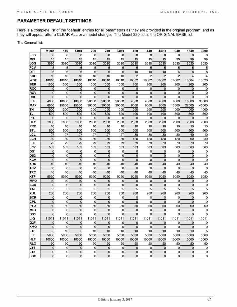
M A G U I R E P R O D U C T S , I N C .
Edition: Janauary 3, 2017 61
W E I G H S C A L E B L E N D E R
PARAMETER DEFAULT SETTINGS Here is a complete list of the "default" entries for all parameters as they are provided in the original program, and as they will appear after a CLEAR ALL or a model change. The Model 220 list is the ORIGINAL BASE list. The General list:
Micro 140 140R 220 240 240R 420 440 440R 940 1840 3000 FLG 0 0 0 0 0 0 0 0 0 0 0 0 MIX 15 15 15 15 15 15 15 15 15 30 99 99 JOG 3030 3030 3030 3030 3030 3030 3030 3030 3030 3030 3030 3030 FCV 5 5 6 5 5 5 5 5 5 5 5 5 DTI 6 6 6 6 6 6 10 10 10 6 8 8 KDF 10 10 10 10 10 10 2 2 2 2 4 4 WDF 10010 10010 10010 10010 10010 10010 10002 10002 10002 10002 10004 10020 BER 1000 1000 1000 1000 1000 1000 200 200 200 200 200 200 ROC 0 0 0 0 0 0 0 0 0 0 0 0 ROV 0 0 0 0 0 0 0 0 0 0 0 0 RHL 0 0 0 0 0 0 0 0 0 0 0 0 FUL 4000 10000 10000 20000 20000 20000 4000 4000 4000 9000 18000 30000 MAX 6000 15000 15000 30000 30000 30000 6000 6000 6000 13500 27000 45000 TH 1000 1000 1000 1000 1000 1000 200 200 200 1000 1000 1000 TL 500 500 500 500 500 500 100 100 100 500 500 500 PRT 0 0 0 0 0 0 0 0 0 0 0 0 DLY 1000 1000 1000 2000 2000 2000 2000 2000 2000 2000 2000 2000 PRC 10 10 10 10 10 10 10 10 10 10 10 10 STL 500 500 500 500 500 500 500 500 500 500 500 500 LCL 27 27 27 27 27 27 80 80 80 80 40 10 LCH 39 39 39 39 39 39 120 120 120 120 60 30 LCF 79 79 79 79 79 79 79 79 79 79 79 79 LCZ 583 583 583 583 583 583 583 583 583 583 583 583 DS1 0 0 0 0 0 0 0 0 0 0 0 0 DS2 0 0 0 0 0 0 0 0 0 0 0 0 XCV 0 0 0 0 0 0 0 0 0 0 0 0 XRC 40 40 40 40 40 40 40 40 40 40 40 40 TCV 0 0 0 0 0 0 0 0 0 0 0 0 TRC 40 40 40 40 40 40 40 40 40 40 40 40 XTP 5020 5050 5020 5050 5050 5050 5050 5050 5050 5050 5050 5050 MPO 10 10 10 0 0 0 0 0 0 0 0 0 SCR 0 0 0 0 0 0 0 0 0 0 0 0 XAL 5 5 5 5 5 5 5 5 5 5 5 5 XUL 200 200 200 200 200 200 200 200 200 200 200 200 BCR 0 0 0 0 0 0 0 0 0 0 0 0 CPL 0 0 0 0 0 0 0 0 0 0 0 0 PTD 60 60 60 60 60 60 60 60 60 60 60 60 MCT 0 0 0 0 0 0 0 0 0 0 0 0 DS3 0 0 0 0 0 0 0 0 0 0 0 0 LIQ 11011 11011 11011 11011 11011 11011 11011 11011 11011 11011 11011 11011 G2F 0 0 0 0 0 0 0 0 0 0 0 0 XMO 0 0 0 0 0 0 0 0 0 0 0 0 LTP 5 10 5 10 10 10 10 10 10 10 10 5 LLF 5000 5000 5000 5000 5000 5000 5000 5000 5000 5000 5000 5000 HLF 10000 10000 10000 10000 10000 10000 10000 10000 10000 10000 10000 10000 RLO 50 50 50 50 50 50 50 50 50 50 50 50 LT1 0 0 0 0 0 0 0 0 0 0 0 0 LT2 0 0 0 0 0 0 0 0 0 0 0 0 SBO 0 0 0 0 0 0 0 0 0 0 0 0
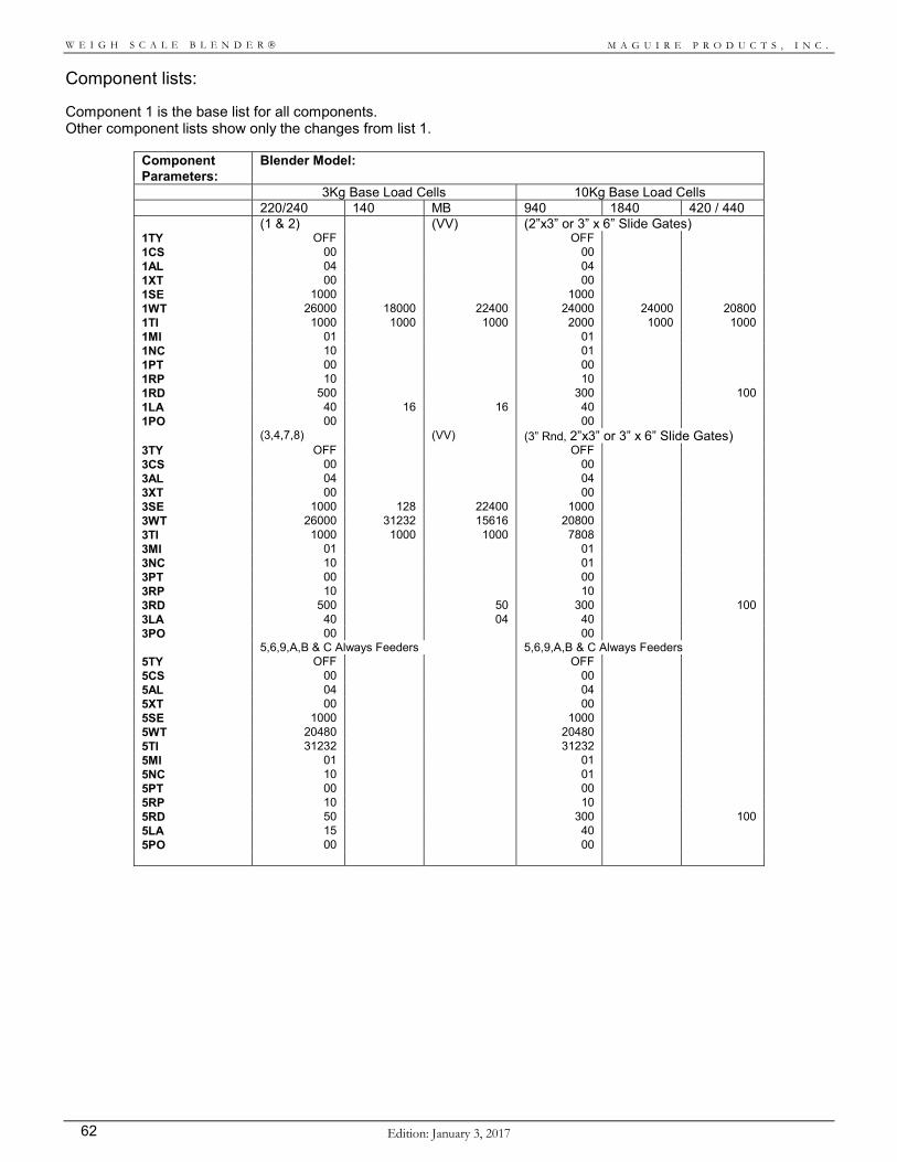
M A G U I R E P R O D U C T S , I N C .
Edition: January 3, 2017 62
W E I G H S C A L E B L E N D E R
Component lists: Component 1 is the base list for all components. Other component lists show only the changes from list 1.
Component Parameters:
Blender Model:
3Kg Base Load Cells 10Kg Base Load Cells 220/240 140 MB 940 1840 420 / 440 (1 & 2) (VV) (2”x3” or 3” x 6” Slide Gates) 1TY OFF OFF 1CS 00 00 1AL 04 04 1XT 00 00 1SE 1000 1000 1WT 26000 18000 22400 24000 24000 20800 1TI 1000 1000 1000 2000 1000 1000 1MI 01 01 1NC 10 01 1PT 00 00 1RP 10 10 1RD 500 300 100 1LA 40 16 16 40 1PO 00 00 (3,4,7,8) (VV) (3” Rnd, 2”x3” or 3” x 6” Slide Gates) 3TY OFF OFF 3CS 00 00 3AL 04 04 3XT 00 00 3SE 1000 128 22400 1000 3WT 26000 31232 15616 20800 3TI 1000 1000 1000 7808 3MI 01 01 3NC 10 01 3PT 00 00 3RP 10 10 3RD 500 50 300 100 3LA 40 04 40 3PO 00 00 5,6,9,A,B & C Always Feeders 5,6,9,A,B & C Always Feeders 5TY OFF OFF 5CS 00 00 5AL 04 04 5XT 00 00 5SE 1000 1000 5WT 20480 20480 5TI 31232 31232 5MI 01 01 5NC 10 01 5PT 00 00 5RP 10 10 5RD 50 300 100 5LA 15 40 5PO 00 00
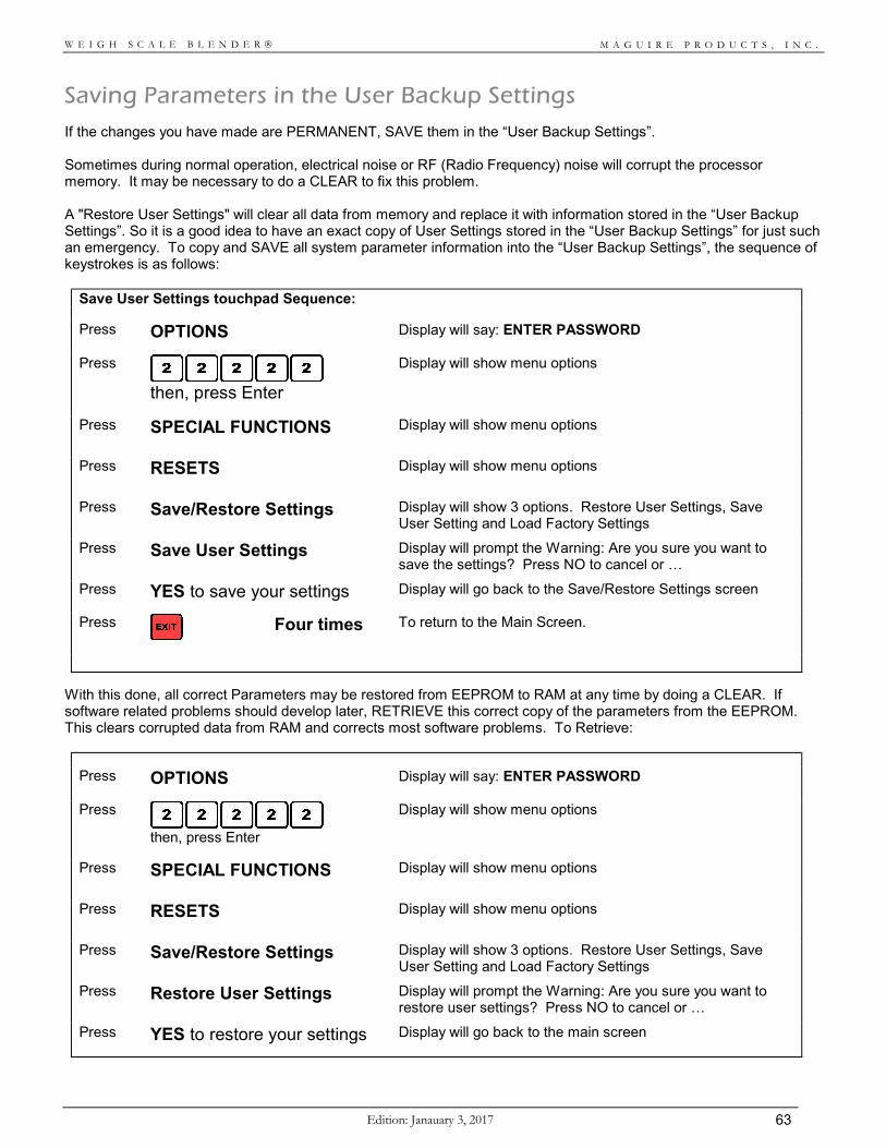
M A G U I R E P R O D U C T S , I N C .
Edition: Janauary 3, 2017 63
W E I G H S C A L E B L E N D E R
Saving Parameters in the User Backup Settings If the changes you have made are PERMANENT, SAVE them in the “User Backup Settings”. Sometimes during normal operation, electrical noise or RF (Radio Frequency) noise will corrupt the processor memory. It may be necessary to do a CLEAR to fix this problem. A "Restore User Settings" will clear all data from memory and replace it with information stored in the “User Backup Settings”. So it is a good idea to have an exact copy of User Settings stored in the “User Backup Settings” for just such an emergency. To copy and SAVE all system parameter information into the “User Backup Settings”, the sequence of keystrokes is as follows:
Save User Settings touchpad Sequence:
Press OPTIONS Display will say: ENTER PASSWORD
Press
then, press Enter
Display will show menu options
Press SPECIAL FUNCTIONS
Display will show menu options
Press RESETS
Display will show menu options
Press Save/Restore Settings
Display will show 3 options. Restore User Settings, Save User Setting and Load Factory Settings
Press Save User Settings
Display will prompt the Warning: Are you sure you want to save the settings? Press NO to cancel or …
Press YES to save your settings Display will go back to the Save/Restore Settings screen
Press
Four times To return to the Main Screen.
With this done, all correct Parameters may be restored from EEPROM to RAM at any time by doing a CLEAR. If software related problems should develop later, RETRIEVE this correct copy of the parameters from the EEPROM. This clears corrupted data from RAM and corrects most software problems. To Retrieve:
Press OPTIONS Display will say: ENTER PASSWORD
Press
then, press Enter
Display will show menu options
Press SPECIAL FUNCTIONS
Display will show menu options
Press RESETS
Display will show menu options
Press Save/Restore Settings
Display will show 3 options. Restore User Settings, Save User Setting and Load Factory Settings
Press Restore User Settings
Display will prompt the Warning: Are you sure you want to restore user settings? Press NO to cancel or …
Press YES to restore your settings Display will go back to the main screen
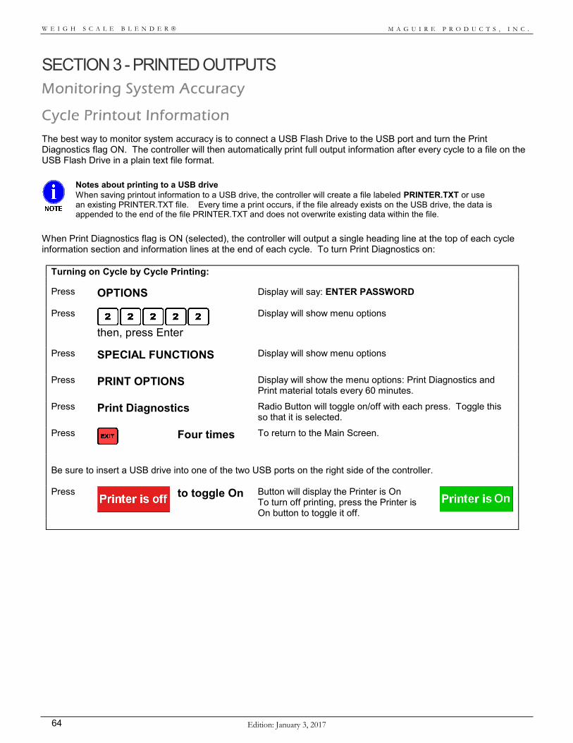
M A G U I R E P R O D U C T S , I N C .
Edition: January 3, 2017 64
W E I G H S C A L E B L E N D E R
SECTION 3 - PRINTED OUTPUTS Monitoring System Accuracy
Cycle Printout Information The best way to monitor system accuracy is to connect a USB Flash Drive to the USB port and turn the Print Diagnostics flag ON. The controller will then automatically print full output information after every cycle to a file on the USB Flash Drive in a plain text file format.
Notes about printing to a USB drive When saving printout information to a USB drive, the controller will create a file labeled PRINTER.TXT or use an existing PRINTER.TXT file. Every time a print occurs, if the file already exists on the USB drive, the data is appended to the end of the file PRINTER.TXT and does not overwrite existing data within the file.
When Print Diagnostics flag is ON (selected), the controller will output a single heading line at the top of each cycle information section and information lines at the end of each cycle. To turn Print Diagnostics on:
Turning on Cycle by Cycle Printing:
Press OPTIONS Display will say: ENTER PASSWORD
Press
then, press Enter
Display will show menu options
Press SPECIAL FUNCTIONS
Display will show menu options
Press PRINT OPTIONS
Display will show the menu options: Print Diagnostics and Print material totals every 60 minutes.
Press Print Diagnostics
Radio Button will toggle on/off with each press. Toggle this so that it is selected.
Press
Four times To return to the Main Screen.
Be sure to insert a USB drive into one of the two USB ports on the right side of the controller. Press
to toggle On Button will display the Printer is On To turn off printing, press the Printer is On button to toggle it off.
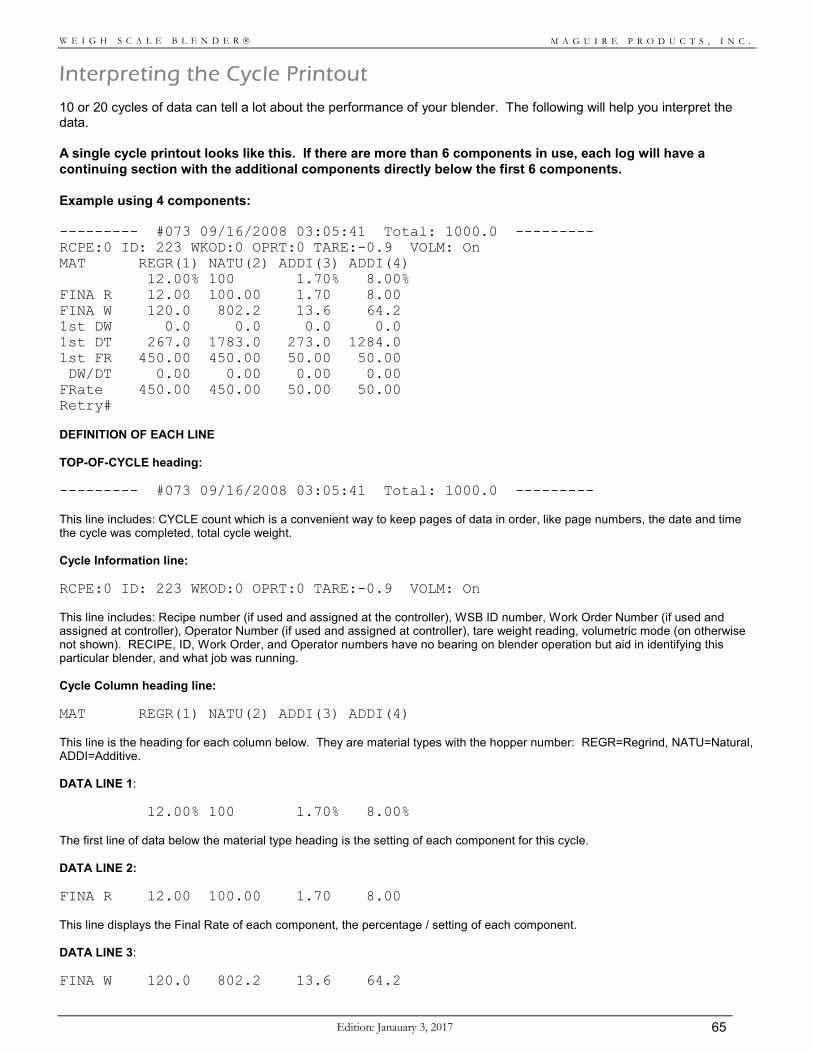
M A G U I R E P R O D U C T S , I N C .
Edition: Janauary 3, 2017 65
W E I G H S C A L E B L E N D E R
Interpreting the Cycle Printout 10 or 20 cycles of data can tell a lot about the performance of your blender. The following will help you interpret the data. A single cycle printout looks like this. If there are more than 6 components in use, each log will have a continuing section with the additional components directly below the first 6 components. Example using 4 components: --------- #073 09/16/2008 03:05:41 Total: 1000.0 --------- RCPE:0 ID: 223 WKOD:0 OPRT:0 TARE:-0.9 VOLM: On MAT REGR(1) NATU(2) ADDI(3) ADDI(4) 12.00% 100 1.70% 8.00% FINA R 12.00 100.00 1.70 8.00 FINA W 120.0 802.2 13.6 64.2 1st DW 0.0 0.0 0.0 0.0 1st DT 267.0 1783.0 273.0 1284.0 1st FR 450.00 450.00 50.00 50.00 DW/DT 0.00 0.00 0.00 0.00 FRate 450.00 450.00 50.00 50.00 Retry# DEFINITION OF EACH LINE TOP-OF-CYCLE heading: --------- #073 09/16/2008 03:05:41 Total: 1000.0 --------- This line includes: CYCLE count which is a convenient way to keep pages of data in order, like page numbers, the date and time the cycle was completed, total cycle weight. Cycle Information line: RCPE:0 ID: 223 WKOD:0 OPRT:0 TARE:-0.9 VOLM: On This line includes: Recipe number (if used and assigned at the controller), WSB ID number, Work Order Number (if used and assigned at controller), Operator Number (if used and assigned at controller), tare weight reading, volumetric mode (on otherwise not shown). RECIPE, ID, Work Order, and Operator numbers have no bearing on blender operation but aid in identifying this particular blender, and what job was running. Cycle Column heading line: MAT REGR(1) NATU(2) ADDI(3) ADDI(4) This line is the heading for each column below. They are material types with the hopper number: REGR=Regrind, NATU=Natural, ADDI=Additive. DATA LINE 1: 12.00% 100 1.70% 8.00% The first line of data below the material type heading is the setting of each component for this cycle. DATA LINE 2: FINA R 12.00 100.00 1.70 8.00 This line displays the Final Rate of each component, the percentage / setting of each component. DATA LINE 3: FINA W 120.0 802.2 13.6 64.2
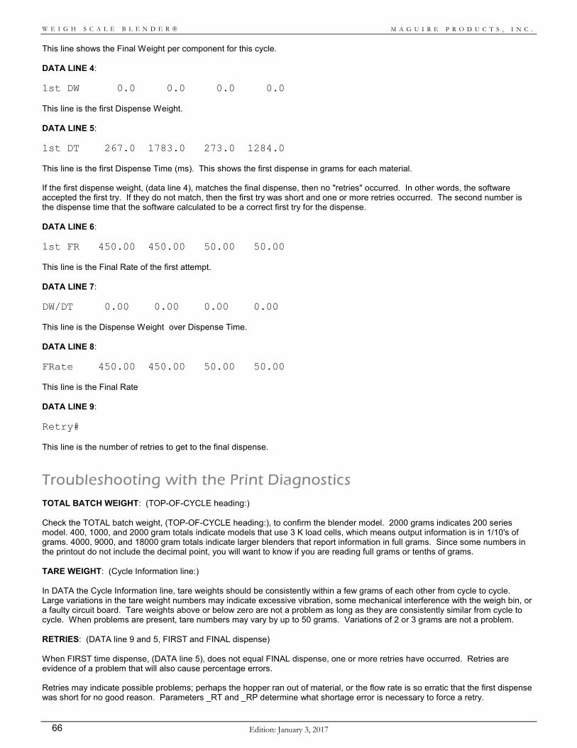
M A G U I R E P R O D U C T S , I N C .
Edition: January 3, 2017 66
W E I G H S C A L E B L E N D E R
This line shows the Final Weight per component for this cycle. DATA LINE 4: 1st DW 0.0 0.0 0.0 0.0 This line is the first Dispense Weight. DATA LINE 5: 1st DT 267.0 1783.0 273.0 1284.0 This line is the first Dispense Time (ms). This shows the first dispense in grams for each material. If the first dispense weight, (data line 4), matches the final dispense, then no "retries" occurred. In other words, the software accepted the first try. If they do not match, then the first try was short and one or more retries occurred. The second number is the dispense time that the software calculated to be a correct first try for the dispense. DATA LINE 6: 1st FR 450.00 450.00 50.00 50.00 This line is the Final Rate of the first attempt. DATA LINE 7: DW/DT 0.00 0.00 0.00 0.00 This line is the Dispense Weight over Dispense Time. DATA LINE 8: FRate 450.00 450.00 50.00 50.00 This line is the Final Rate DATA LINE 9: Retry# This line is the number of retries to get to the final dispense.
Troubleshooting with the Print Diagnostics TOTAL BATCH WEIGHT: (TOP-OF-CYCLE heading:) Check the TOTAL batch weight, (TOP-OF-CYCLE heading:), to confirm the blender model. 2000 grams indicates 200 series model. 400, 1000, and 2000 gram totals indicate models that use 3 K load cells, which means output information is in 1/10's of grams. 4000, 9000, and 18000 gram totals indicate larger blenders that report information in full grams. Since some numbers in the printout do not include the decimal point, you will want to know if you are reading full grams or tenths of grams. TARE WEIGHT: (Cycle Information line:) In DATA the Cycle Information line, tare weights should be consistently within a few grams of each other from cycle to cycle. Large variations in the tare weight numbers may indicate excessive vibration, some mechanical interference with the weigh bin, or a faulty circuit board. Tare weights above or below zero are not a problem as long as they are consistently similar from cycle to cycle. When problems are present, tare numbers may vary by up to 50 grams. Variations of 2 or 3 grams are not a problem. RETRIES: (DATA line 9 and 5, FIRST and FINAL dispense) When FIRST time dispense, (DATA line 5), does not equal FINAL dispense, one or more retries have occurred. Retries are evidence of a problem that will also cause percentage errors. Retries may indicate possible problems; perhaps the hopper ran out of material, or the flow rate is so erratic that the first dispense was short for no good reason. Parameters _RT and _RP determine what shortage error is necessary to force a retry.
M A G U I R E P R O D U C T S , I N C .
Edition: Janauary 3, 2017 67
W E I G H S C A L E B L E N D E R
FLOW RATE NUMBERS: (DATA line 2) Check the RATE numbers, (DATA line 2), to determine each dispense device. In the example above: In the component 1 column, 18224 and 976 translates to 1822.4 grams in 4 seconds (244 interrupts = 1 sec). This is 455.6 grams per second, typical for a regrind flowing through 3" round or 2"x3" dispense valves. In the component 2 column, 19993 and 488 indicate 1999.3 grams in 2 seconds, or 999.6 grams per second flow rate. This is a heavy natural material, not polyethylene. Perhaps Lexan or a glass filled material. In the component 3 column, 12973 and 31232 indicate 1297.3 grams per 31232 interrupts, or 128 seconds, for a flow rate of 9.99 grams per second. This is a 1” auger feeder, from which we would typically expect about 8 grams per second. More recent auger feeders use faster motors delivering about 16 grams per second. In the component 4 column, 10240 and 31232 indicate a flow rate of 8 grams per second EXACTLY. Since it is exact, and since these two numbers are, in fact, the "default" settings from when the blender was first installed, we know that "component 4" has never been run on this blender, or at least not since the last "CLEAR ALL" was performed. DATA line 3 dispense weight of 0.0 for component 4, and the TOP-OF-PAGE heading showing component 4 set to 00.0 percent also confirm that component 4 is not being run. The following information will help you determine what devices are in place on a blender. Material Dispense Device: Approx. Grams
per Second: ½” Auger Feeders, Micro Pulse Valves 0.5 - 02 1” Auger Feeders 06 - 10 Vertical Valves 20 - 40 WSB 100 - Slide Gates 250 - 450 WSB 220, 420 - 3” Round Slide Gates 500 - 900 WSB 240, 260, 440, 460, 940, 960, 1840, 1860 - 2” x 3” Slide Gates 500 - 900 WSB 240, 260, 440, 460, 940, 960, 1840, 1860 - 3” x 6” Slide Gates 3000 - 5000 Regrinds are always lower then naturals. Bulk density will also cause wide variations in flow rates. ERROR CORRECTIONS: RATE NUMBERS: (DATA line 2) The RATE numbers are used by the software, each cycle, to calculate material dispense times. They are adjusted every cycle until flow rates stabilize. When a significant error is detected, the software adjusts the RATE numbers. The GRAM number is adjusted first. The TIME number (interrupts) is changed only if the GRAM number goes below 16,000 or above 32,000 (approximately). In this event both GRAM and TIME numbers are doubled or halved to bring the GRAM number back to between 16,000 and 32,000. This serves to keep all numbers as large as possible allowing for the most accurate math, but not so large as to overflow the registers. Only the GRAM number changes from cycle to cycle, except under the conditions noted above. Check the GRAM number for a series of consecutive cycles. If it remains unchanged, then the dispenses are accurate enough to not trigger error corrections. Another possibility is that the parameters (MI and NC) that determine when error corrections occur are somehow out of range preventing corrections that should be occurring. The PRC parameter limits adjustments to 10 percent. Do not expect any single GRAM number change larger then 10 percent. A gradual decrease in the GRAM number indicates a slowing rate, a hopper that is becoming empty for example. A jump in rate (increased GRAM number) occurs when the hopper is refilled. If Errors are occurring, but the GRAM number is NOT adjusting, check the NC parameter and the MI parameter. These control weather or not error corrections occur. Both are set and adjusted automatically by the software. MI is set after each start up, after 10 cycles have run without retries. MI will be set to indicate 50 percent of normal dispense rate expressed as grams per second. NC adjusts slowly over extended periods of running. NC indicates, in grams, the upper limit of the error in 60 percent of the dispenses. A high number usually indicates poor flowing material. Vibration or drifting load cells are other possibilities. DISPENSE TIMING: (DATA line 3)
M A G U I R E P R O D U C T S , I N C .
Edition: January 3, 2017 68
W E I G H S C A L E B L E N D E R
The second number is the number of interrupts calculated to dispense the material. If these times are consistent but the weight of the first dispense varies, then the material does not flow well, or consistently. Another possibility is excessive vibration or interference with the weigh bin. Excess vibration, particularly on small dispenses, may cause incorrect weight readings even though the weight dispensed was, in fact, correct. If the timing number is very small, 10, 20, 30 interrupts, perhaps this is asking too much from a slide valve. Very short times mean you want small amounts, but are using a high rate dispense valve to do the job. An auger, a vertical valve, a horizontal valve with a flow restrictor, or a smaller valve would help to improve accuracy and control. If the timing number is below 5, you are operating in a range were it is difficult for the blender to perform well. The LAG time parameter adds time to every dispense. This is to compensate for the time at the beginning of a dispense when the solenoid valve shifts and air pressure builds, before the valve starts to move. LAG times are always set slightly longer then the necessary minimum. If a calculated dispense time is very short, the Lag time that is added, while small, may interfere with accuracy, and cause an over dispense. PERCENTAGE ERRORS: (DATA line 1) When looking at errors of percentage of color or additive dispensed, look further.
1. First, look for indications of "retries". Retries are evidence of a problem that will also cause percentage errors. When FIRST time dispense, (DATA line 3), does not equal FINAL dispense, (DATA line 1), one or more retries have occurred. This means the hopper ran out of material, or the flow rate is so erratic that the first dispense was short for no good reason. Parameters _RT and _RP determine what shortage error is necessary to force a retry. Inconsistent loading resulting in large variations in hopper material level can cause retries. Excessive vibration can also cause bad weight readings, which can cause unwarranted retries. If the BAILOUT line is printing occasionally, then vibration is most likely causing this. Increasing the BAILOUT parameter should fix this. A LAG time set too high may cause retries to overshoot their mark resulting in over dispensing.
2. Second, look at ACTUAL weight dispensed (DATA line 1).
Color, for example, is a percentage of the natural. In the example above, Natural is 1908.3 grams, so color, at 4 percent of Natural, is targeted to be 76.3 grams. In fact, 77.6 were dispensed. The error is 1.3 grams, well within the expected accuracy of a 1” auger feeder. The actual GRAM error of a dispense is more meaningful then the percentage error. Mechanical devices are not perfect. The most we can expect from them is to operate within a reasonable range of accuracy. This range is better defined by an error expressed in grams, rather them percentage.
3. Third, look at the dispense TIME (DATA line 3). Very short times (10, 20, 30 interrupts) indicate dispense devices not well matched to the task. Accuracy on a percentage basis, cycle to cycle, will suffer. This may very well be acceptable as long as overall usage percentages are still accurate.
BAILOUT: (line 4) If bailouts occur, vibration is usually the cause and these bailouts may be causing other problems. Raise the value of the BAL parameter to 200 or 300 grams to reduce or eliminate unnecessary bailouts. Vibration may also cause throughput rates to suffer due to the added time required to obtain acceptable weight readings. Increase the WDF parameter to 2 or 3 grams, (WDF 00003) or (WDF 00030), or more if necessary.
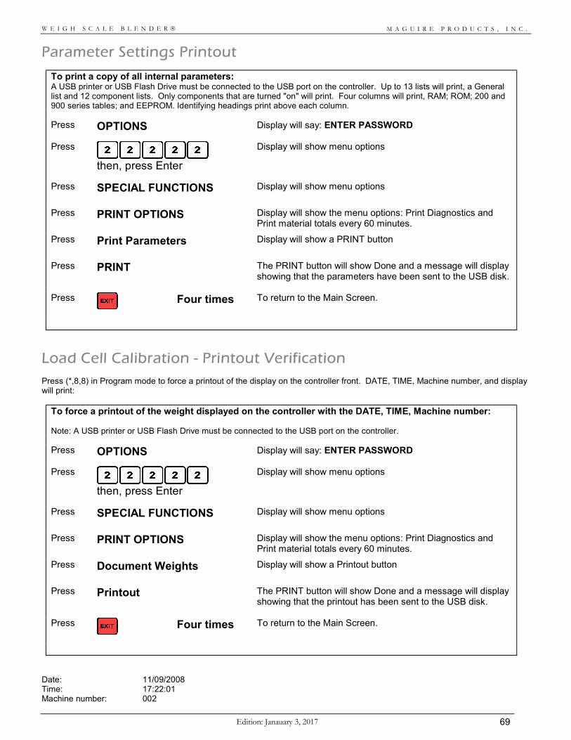
M A G U I R E P R O D U C T S , I N C .
Edition: Janauary 3, 2017 69
W E I G H S C A L E B L E N D E R
Parameter Settings Printout
To print a copy of all internal parameters: A USB printer or USB Flash Drive must be connected to the USB port on the controller. Up to 13 lists will print, a General list and 12 component lists. Only components that are turned "on" will print. Four columns will print, RAM; ROM; 200 and 900 series tables; and EEPROM. Identifying headings print above each column.
Press OPTIONS Display will say: ENTER PASSWORD
Press
then, press Enter
Display will show menu options
Press SPECIAL FUNCTIONS
Display will show menu options
Press PRINT OPTIONS
Display will show the menu options: Print Diagnostics and Print material totals every 60 minutes.
Press Print Parameters
Display will show a PRINT button
Press PRINT
The PRINT button will show Done and a message will display showing that the parameters have been sent to the USB disk.
Press
Four times To return to the Main Screen.
Load Cell Calibration - Printout Verification
Press (*,8,8) in Program mode to force a printout of the display on the controller front. DATE, TIME, Machine number, and display will print:
To force a printout of the weight displayed on the controller with the DATE, TIME, Machine number: Note: A USB printer or USB Flash Drive must be connected to the USB port on the controller.
Press OPTIONS Display will say: ENTER PASSWORD
Press
then, press Enter
Display will show menu options
Press SPECIAL FUNCTIONS
Display will show menu options
Press PRINT OPTIONS
Display will show the menu options: Print Diagnostics and Print material totals every 60 minutes.
Press Document Weights
Display will show a Printout button
Press Printout
The PRINT button will show Done and a message will display showing that the printout has been sent to the USB disk.
Press
Four times To return to the Main Screen.
Date: 11/09/2008 Time: 17:22:01 Machine number: 002
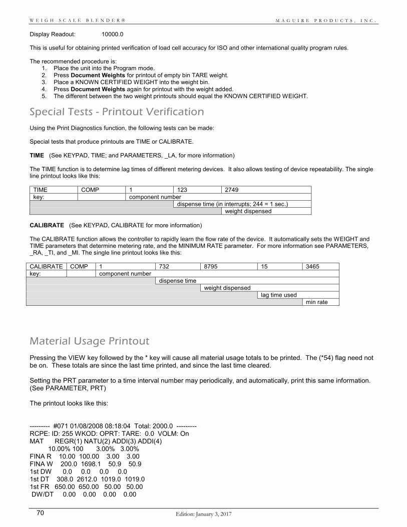
M A G U I R E P R O D U C T S , I N C .
Edition: January 3, 2017 70
W E I G H S C A L E B L E N D E R
Display Readout: 10000.0 This is useful for obtaining printed verification of load cell accuracy for ISO and other international quality program rules. The recommended procedure is:
1. Place the unit into the Program mode. 2. Press Document Weights for printout of empty bin TARE weight. 3. Place a KNOWN CERTIFIED WEIGHT into the weight bin. 4. Press Document Weights again for printout with the weight added. 5. The different between the two weight printouts should equal the KNOWN CERTIFIED WEIGHT.
Special Tests - Printout Verification Using the Print Diagnostics function, the following tests can be made: Special tests that produce printouts are TIME or CALIBRATE. TIME (See KEYPAD, TIME; and PARAMETERS, _LA, for more information) The TIME function is to determine lag times of different metering devices. It also allows testing of device repeatability. The single line printout looks like this:
TIME COMP 1 123 2749 key: component number dispense time (in interrupts; 244 = 1 sec.) weight dispensed
CALIBRATE (See KEYPAD, CALIBRATE for more information) The CALIBRATE function allows the controller to rapidly learn the flow rate of the device. It automatically sets the WEIGHT and TIME parameters that determine metering rate, and the MINIMUM RATE parameter. For more information see PARAMETERS, _RA, _TI, and _MI. The single line printout looks like this: CALIBRATE COMP 1 732 8795 15 3465 key: component number dispense time weight dispensed lag time used min rate
Material Usage Printout Pressing the VIEW key followed by the * key will cause all material usage totals to be printed. The (*54) flag need not be on. These totals are since the last time printed, and since the last time cleared. Setting the PRT parameter to a time interval number may periodically, and automatically, print this same information. (See PARAMETER, PRT) The printout looks like this: --------- #071 01/08/2008 08:18:04 Total: 2000.0 --------- RCPE: ID: 255 WKOD: OPRT: TARE: 0.0 VOLM: On MAT REGR(1) NATU(2) ADDI(3) ADDI(4) 10.00% 100 3.00% 3.00% FINA R 10.00 100.00 3.00 3.00 FINA W 200.0 1698.1 50.9 50.9 1st DW 0.0 0.0 0.0 0.0 1st DT 308.0 2612.0 1019.0 1019.0 1st FR 650.00 650.00 50.00 50.00 DW/DT 0.00 0.00 0.00 0.00
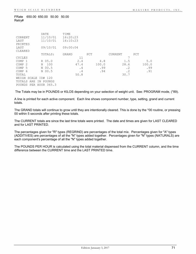
M A G U I R E P R O D U C T S , I N C .
Edition: Janauary 3, 2017 71
W E I G H S C A L E B L E N D E R
FRate 650.00 650.00 50.00 50.00 Retry# DATE TIME CURRENT 11/10/01 16:20:23 LAST PRINTED
11/10/01 16:10:23
LAST CLEARED
09/10/01 09:00:04
TOTALS: GRAND PCT CURRENT PCT CYCLES 11 7 COMP 1 R 05.0 2.4 4.8 1.5 5.0 COMP 2 N 100 47.4 100.0 28.6 100.0 COMP 5 N 00.5 .4 .99 .2 .99 COMP 6 N 00.5 .4 .94 .2 .91 TOTAL 50.8 30.7 WEIGH SCALE ID# 120 TOTALS ARE IN POUNDS POUNDS PER HOUR 365.3
The Totals may be in POUNDS or KILOS depending on your selection of weight unit. See: PROGRAM mode, (*89). A line is printed for each active component. Each line shows component number, type, setting, grand and current totals. The GRAND totals will continue to grow until they are intentionally cleared. This is done by the *00 routine, or pressing 00 within 5 seconds after printing these totals. The CURRENT totals are since the last time totals were printed. The date and times are given for LAST CLEARED and for LAST PRINTED. The percentages given for "R" types (REGRIND) are percentages of the total mix. Percentages given for "A" types (ADDITIVES) are percentages of all the "N" types added together. Percentages given for "N" types (NATURALS) are each component's percentage of all the "N" types added together. The POUNDS PER HOUR is calculated using the total material dispensed from the CURRENT column, and the time difference between the CURRENT time and the LAST PRINTED time.
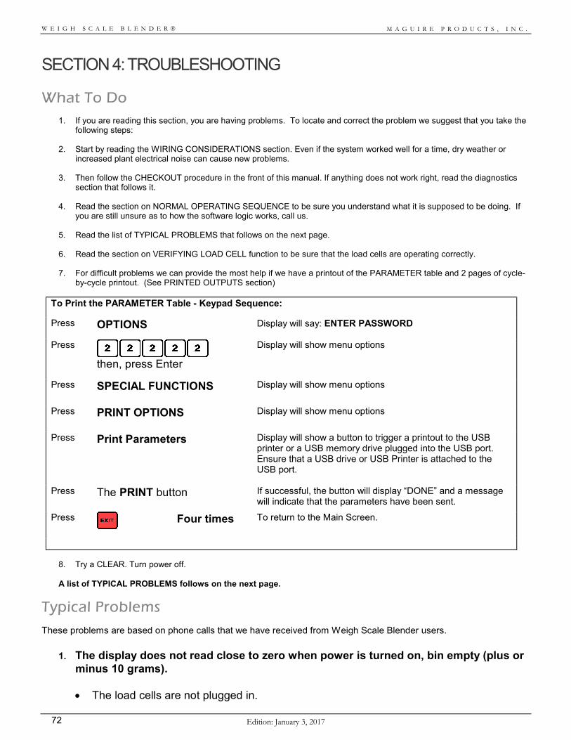
M A G U I R E P R O D U C T S , I N C .
Edition: January 3, 2017 72
W E I G H S C A L E B L E N D E R
SECTION 4: TROUBLESHOOTING
What To Do
1. If you are reading this section, you are having problems. To locate and correct the problem we suggest that you take the following steps:
2. Start by reading the WIRING CONSIDERATIONS section. Even if the system worked well for a time, dry weather or
increased plant electrical noise can cause new problems.
3. Then follow the CHECKOUT procedure in the front of this manual. If anything does not work right, read the diagnostics section that follows it.
4. Read the section on NORMAL OPERATING SEQUENCE to be sure you understand what it is supposed to be doing. If
you are still unsure as to how the software logic works, call us.
5. Read the list of TYPICAL PROBLEMS that follows on the next page.
6. Read the section on VERIFYING LOAD CELL function to be sure that the load cells are operating correctly.
7. For difficult problems we can provide the most help if we have a printout of the PARAMETER table and 2 pages of cycle-by-cycle printout. (See PRINTED OUTPUTS section)
To Print the PARAMETER Table - Keypad Sequence:
Press OPTIONS Display will say: ENTER PASSWORD
Press
then, press Enter
Display will show menu options
Press SPECIAL FUNCTIONS
Display will show menu options
Press PRINT OPTIONS
Display will show menu options
Press Print Parameters Display will show a button to trigger a printout to the USB printer or a USB memory drive plugged into the USB port. Ensure that a USB drive or USB Printer is attached to the USB port.
Press The PRINT button
If successful, the button will display “DONE” and a message will indicate that the parameters have been sent.
Press
Four times To return to the Main Screen.
8. Try a CLEAR. Turn power off.
A list of TYPICAL PROBLEMS follows on the next page.
Typical Problems These problems are based on phone calls that we have received from Weigh Scale Blender users.
1. The display does not read close to zero when power is turned on, bin empty (plus or minus 10 grams).
The load cells are not plugged in.
M A G U I R E P R O D U C T S , I N C .
Edition: Janauary 3, 2017 73
W E I G H S C A L E B L E N D E R
The weigh bin is not resting properly and freely in its platform or the platform is not resting properly on the bolts that protrude from the load cell enclosures.
The controller was never calibrated for these load cells or you just did a CLEAR ALL. In this case it will most likely be off by several hundred grams. See LOAD CELL CALIBRATION.
The load cells are damaged. See CHECKING THE LOAD CELLS
2. The Controller "RESETS" itself for no reason. This indicates electrical noise or voltage spikes disrupting the processor.
See WIRING CONSIDERATIONS, ASSEMBLY section.
3. The ALARM is flashing and the display shows a weight above 100 or below -50
grams. If above 100, the Weigh bin dump valve keeps opening and closing every 6 or 7 seconds.
There is material in the weigh bin that will not dump out. The dump flap may be stuck. The load cells are hung up or obstructed. The load cells are out of calibration. Incorrect grounding is causing wide load cell readouts.
4. The VERY FIRST DISPENSE does NOT take place. After a few seconds the ALARM
begins to flash. The display says (N x.x) and is flashing.
The air supply is not connected or the pressure is set too low. The Natural solenoid is not connected properly. The 1/2 amp panel front fuse is blown. The NATURAL slide gate is jammed. The cylinder mount may be bent.
5. The NATURAL dispense valve continues to dump repeatedly even though the weigh
bin has filled to overflowing. The weight reading is still below 2000.0 grams.
The weigh bin is not free to move. The load cells are jammed. The load cells are damaged. See CHECKING THE LOAD CELLS
6. The system operates but always needs MANY RETRIES to complete a dispense and
never seems to "learn" the proper dispense rate. Vibration is causing frequent "bailouts" causing large swings in rate adjustment.
Increase the BER parameter.
7. The THUMBWHEEL SWITCHES do not seem to be controlling output. Someone has LOCKED IN a setting using the keypad. See KEYPAD, PROGRAM
MODE, SETTING. The _SE parameter is LIMITING the thumbwheel switch setting. See KEYPAD,
PROGRAM MODE, and PARAMETERS, _SE.
M A G U I R E P R O D U C T S , I N C .
Edition: January 3, 2017 74
W E I G H S C A L E B L E N D E R
8. Occasionally, the system gets STUCK doing retries of a component but the retry time is so short that nothing gets dispensed.
The LAG TIME parameter is set for too short a time. See KEYPAD, TIME, and
PARAMETER, _LA. A valve is sticking closed. Check for free operation when air pressure is removed.
9. The system USED TO WORK but now it does unexplainable things.
Static or a voltage surge has altered RAM memory. Do a CLEAR or CLEAR ALL. See
"CLEAR" RESTART or "CLEAR ALL" RESTART. Then do a LOAD CELL CALIBRATION, and RATE CALIBRATION for ALL materials.
10. The Display reads 3100.0 even with the bin empty. This is the upper limit load cell
readout.
The Load Cells are not plugged in and the circuitry has drifted to the top limit. The Load Cells have been overloaded way beyond their limit and are now permanently
deflected.
11. Dispenses from a slide gate are not as consistent as they should be.
The slide gate is sticking slightly. With the hopper empty, move the slide manually to see that it moves freely. Press up or down on the air cylinder to adjust for proper alignment.
The material does not flow very well. A bridge breaker adaptor may be required.
12. Load Cell weight readings are not holding steady. They vary as much as 100 grams from second to second.
This is static and improper grounding. See WIRING CONSIDERATIONS If readings drift slowly in one direction, requiring frequent recalibration, a component on
the circuit board is most likely faulty. Call us. If TARE weights are not steady, something may be physically interfering with free
movement of the cells.
13. At the end of each cycle the MIX MOTOR runs for a fraction of a second only.
The MIX MOTOR pulls a heavy amp load on start up. If the power supply is not adequate (like when using an extension cord), the voltage will drop so low that the computer will reset and the mix motor signal will shut off. The display will show this by restarting as if power was just turned on. Provide a better supply of power; remove extension cord or use larger gage wire.
Mix Problems
Customers with mix problems have several options available. Decrease the batch size by lowering the FUL parameter value. This does two things. First, it causes the components to be dispensed in smaller, more frequent batches, which places more and smaller layers of material into the mix chamber. Second, it lowers the level of material in the mix chamber immediately after a dispense. It is critical to proper mixing that the mix blades reach up through the top of the material in the mix chamber during mix time. Dispensing a large batch may bury these blades,

M A G U I R E P R O D U C T S , I N C .
Edition: Janauary 3, 2017 75
W E I G H S C A L E B L E N D E R
particularly when the process is not running at full blender capacity. A smaller batch size, while reducing throughput rate, will help prevent the mix blades being covered during mix time. Be sure level sensor is mounted in its lowest position, and increase sensitivity as much as possible. Both serve to keep a batch from being dispensed so early as to cover the mix blades. On units without flow control valves (FCA), increase the DLY parameter to as number as high as 50 percent of the time between cycles. DLY is the time delay (in milliseconds) from the sensor being uncovered until we begin the batch. Increasing DLY allows the mix chamber to empty somewhat before the next batch drops. You may increase the mix time at the end of each batch by changing the last two digits of the MIX parameter. If throughput is very high it may be better to run the mixer continuously. However, added mix time sometimes causes separation after an initial mixing. Different bulk densities and static electricity both aggravate this potential for separation from excessive mixing. If a blender is mounted on a stand over a surge hopper, there should be a FCA, automatic flow control valve, fitted to the bottom of the blender. This valve must be plumbed so that it is closed when the level sensor is uncovered. When the sensor is covered the valve opens to release material. The purpose of this valve is to ensure mixing. The FCV parameter delays the opening of this valve for 6 seconds. You can increase this delay time if you feel additional mixing is required before release. On model WSB-940, be sure the weigh bin has two baffles installed. These ensure horizontal layering (as opposed to side by side layering) of materials prior to dropping into the mix chamber. Bulk density and pellet shape differences, specifically smooth virgin pellets mixed with square higher density color pellets, can separate when dropped onto a sloping pile, as exists in a hopper, Gaylord, or surge bin. The light round pellets flow like water to the edges, while the heavier square color pellets stay put. This is difficult to correct. It is best not to drop these kinds of blends into large containers. Vacuum conveying can also separate materials of different bulk densities. Maintain high air velocity to minimize this. Models WSB-MB series units use an air drive for the mix blade, instead of an electric motor. If you are having mix problems with air drives, be sure the blades moves a full 270 degrees (3/4 turn) with each sweep. If they do not, try the following: Increase the air pressure. If the gauge pressure drops more then 5 pounds during operation of the blades, the air supply line is too small. Lower the pile in the mix chamber to reduce torque requirements on the mix blade. This is explained above. Increase the MPO parameter from 122 (1/2 second) to 183 (3/4 second) or 244 (1 full second). This allows more time for a full mix blade sweep to occur. You may also want to increase mix time from 10 seconds to 15 or 20 seconds so that, in spite of slower mix blade speed, the same amount of mixing occurs.
Increasing Throughput A correctly sized blender should have throughput that always exceeds your process requirements. If, for some reason, your blender is not keeping up, here are a few ways to increase throughput.
1. If your blender is equipped with a flow control slide gate, under the blender, this will reduce throughput up to 25 percent. To counter this, set the "END FULL" flag on using the *44 function explained earlier. In the END FULL mode, blending begins even while the sensor is still covered due to flow control valve operation.
2. If your process consumes a large batch of material all at once (such as during injection and screw return time), and
material reserve is not adequate, you may "run out" of material for a few seconds while the Weigh Scale blender is making a new batch. The *44, "END FULL" function will also correct this. Here, when the sensor is uncovered, a completed batch is immediately available to help refill the mix chamber, providing a larger reserve to the process.
3. Increase the FUL parameter. This sets the batch size. Larger batches increase throughput. Depending on the bulk
density of your material, you may be able to increase batch size by 20 to 40 percent.
4. Turn "FAST" on. This causes rapid volumetric "timed" dispenses to occur up to 4 times after each normal gravimetric dispense.
5. Do not confuse "reserve" with "throughput". If your blender has a temporary problem which results in your process
running out of material before you have time to remedy the problem, your "reserve" is inadequate. Add a surge hopper, or material level alarms on individual hoppers to prevent these types of problems.
M A G U I R E P R O D U C T S , I N C .
Edition: January 3, 2017 76
W E I G H S C A L E B L E N D E R
Normal Operating Sequence This section tells you how the system is supposed to work. If your system is not operating correctly, this description may help you spot exactly where the system is failing, providing a clue to the problem.
Turn POWER ON: The current program version date (V=xxxxxT) is displayed for 1 second, followed by the check
sum number (CKS xxxx), followed by a ROM check (ROM OK ), followed by a display of ( 0). The weight in the weight bin is now displayed. It should be 0 plus or minus several grams. During the first few minutes of operation, the displayed weight readings may drift slightly as the circuitry warms up.
BEGIN operation: The unit will begin to operate if both switches on the left side are UP in the CONTINUE position
and the SENSOR in the mix chamber is UNCOVERED. The sensor must be plugged into the right side of the controller. If it is not, this has the same effect as the sensor being covered; the unit will not run.
If the WEIGH BIN DUMP Flap opens and closes repeatedly: If initial empty bin TARE weight is 100 grams or more, the weigh bin dump valve will operate in
an attempt to empty the bin and bring the starting weight closer to zero. If the bin is empty but the weight reading is greater than 100 grams then something is wrong. See TESTING the LOAD CELLS and LOAD CELL CALIBRATION.
If the ALARM flashes: If the initial TARE weight is below -50 grams the Alarm will flash and the unit will not operate. Go
to TESTING of LOAD CELLS and LOAD CELL CALIBRATION.
The DISPENSE sequence begins: If initial tare weight is within limits, between -50 and +100, the sequence will begin.
DISPLAY during dispenses: During all dispenses, the component number and Type letter (R,N,A) will be displayed indicating
which component is being dispensed. The INITIAL display is the tare weight of the bin. This will not change during the first dispense. After each dispense, the new total weight of the material in the bin is updated and displayed.
REGRINDS first: If REGRIND is part of the blend, REGRIND dispenses will occur first in order of size, from
the largest to the smallest. The letter "R" will appear in the display. After these dispenses an exact weight is taken to determine the space remaining in the weigh bin for the remaining dispenses. The total bin weight will appear in the display 2 seconds AFTER each dispense has ended.
NATURALS second: The NATURAL dispenses occur next in the sequence. They will be dispensed in order of
size, largest to smallest. The letter "N" will appear in the display. The exact weight of all NATURAL dispensed is now determined for calculating the ADDITIVE dispenses.
ADDITIVES third: The ADDITIVE dispenses occur last in the sequence. Each dispense must meet
requirements set by internal parameters or RETRIES will occur and the sequence will not continue.
MATERIAL RUNS OUT: If any material runs out or is not enough to meet criteria set by parameters then the process
M A G U I R E P R O D U C T S , I N C .
Edition: Janauary 3, 2017 77
W E I G H S C A L E B L E N D E R
will NOT CONTINUE past this component. RETRIES of this dispense will occur indefinitely until the full dispense occurs or power is turned off. The display will FLASH. The ALARM will sound after 4 retries. This number of retries before alarm is based on the ALARM (_AL) parameters. REGRIND may, or may not, be set to cause an alarm when it runs out. See PARAMETERS, _AL, for how to set the ALARM parameters.
If ALARM flashes: More than four retries of any single component will cause the strobe light ALARM to begin
flashing. The component that is causing the alarm will continue to retry the dispense. The display will blink and the first digit in the display will signify which component is causing the problem. To continue with the dispense sequence, you must satisfy the requirements of the dispense or turn power off.
WEIGH BIN dump: After all dispenses the weigh bin is emptied by the final dump of the weigh bin into the
mixing chamber. The dump valve remains open for four seconds. (DTI parameter)
SENSOR covered: While the sensor is covered, the dump valve remains open to ensure the weigh bin empties
completely. Dispensing stops. The dump valve will remain open for as long as the sensor is covered. This will be until the next cycle begins.
FLOW CONTROL Valve: (optional) The Flow Control Valve under the mix chamber will stay closed for 6 seconds (FCV
parameter) immediately following a dispense into the mix chamber. The rest of the time it opens when the sensor is covered, and closes when the sensor has been uncovered for at least two full seconds (based on DLY parameter).
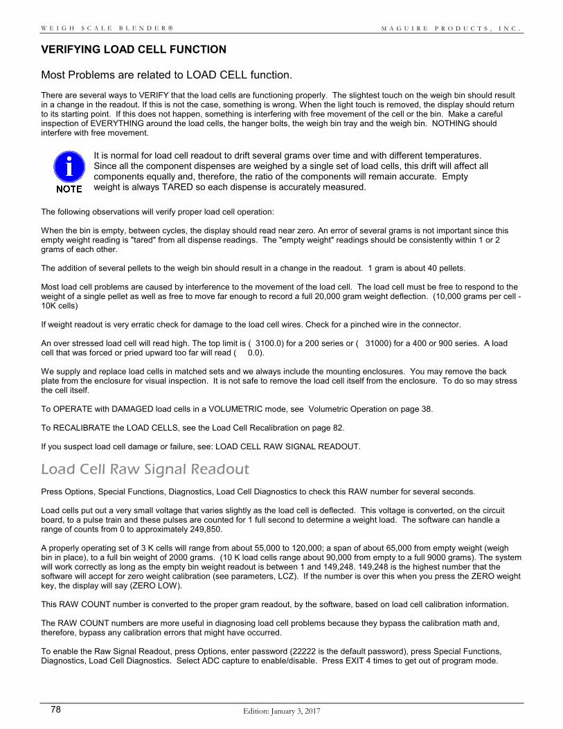
M A G U I R E P R O D U C T S , I N C .
Edition: January 3, 2017 78
W E I G H S C A L E B L E N D E R
VERIFYING LOAD CELL FUNCTION Most Problems are related to LOAD CELL function. There are several ways to VERIFY that the load cells are functioning properly. The slightest touch on the weigh bin should result in a change in the readout. If this is not the case, something is wrong. When the light touch is removed, the display should return to its starting point. If this does not happen, something is interfering with free movement of the cell or the bin. Make a careful inspection of EVERYTHING around the load cells, the hanger bolts, the weigh bin tray and the weigh bin. NOTHING should interfere with free movement.
It is normal for load cell readout to drift several grams over time and with different temperatures. Since all the component dispenses are weighed by a single set of load cells, this drift will affect all components equally and, therefore, the ratio of the components will remain accurate. Empty weight is always TARED so each dispense is accurately measured.
The following observations will verify proper load cell operation: When the bin is empty, between cycles, the display should read near zero. An error of several grams is not important since this empty weight reading is "tared" from all dispense readings. The "empty weight" readings should be consistently within 1 or 2 grams of each other. The addition of several pellets to the weigh bin should result in a change in the readout. 1 gram is about 40 pellets. Most load cell problems are caused by interference to the movement of the load cell. The load cell must be free to respond to the weight of a single pellet as well as free to move far enough to record a full 20,000 gram weight deflection. (10,000 grams per cell - 10K cells) If weight readout is very erratic check for damage to the load cell wires. Check for a pinched wire in the connector. An over stressed load cell will read high. The top limit is ( 3100.0) for a 200 series or ( 31000) for a 400 or 900 series. A load cell that was forced or pried upward too far will read ( 0.0). We supply and replace load cells in matched sets and we always include the mounting enclosures. You may remove the back plate from the enclosure for visual inspection. It is not safe to remove the load cell itself from the enclosure. To do so may stress the cell itself. To OPERATE with DAMAGED load cells in a VOLUMETRIC mode, see Volumetric Operation on page 38. To RECALIBRATE the LOAD CELLS, see the Load Cell Recalibration on page 82. If you suspect load cell damage or failure, see: LOAD CELL RAW SIGNAL READOUT.
Load Cell Raw Signal Readout Press Options, Special Functions, Diagnostics, Load Cell Diagnostics to check this RAW number for several seconds. Load cells put out a very small voltage that varies slightly as the load cell is deflected. This voltage is converted, on the circuit board, to a pulse train and these pulses are counted for 1 full second to determine a weight load. The software can handle a range of counts from 0 to approximately 249,850. A properly operating set of 3 K cells will range from about 55,000 to 120,000; a span of about 65,000 from empty weight (weigh bin in place), to a full bin weight of 2000 grams. (10 K load cells range about 90,000 from empty to a full 9000 grams). The system will work correctly as long as the empty bin weight readout is between 1 and 149,248. 149,248 is the highest number that the software will accept for zero weight calibration (see parameters, LCZ). If the number is over this when you press the ZERO weight key, the display will say (ZERO LOW). This RAW COUNT number is converted to the proper gram readout, by the software, based on load cell calibration information. The RAW COUNT numbers are more useful in diagnosing load cell problems because they bypass the calibration math and, therefore, bypass any calibration errors that might have occurred. To enable the Raw Signal Readout, press Options, enter password (22222 is the default password), press Special Functions, Diagnostics, Load Cell Diagnostics. Select ADC capture to enable/disable. Press EXIT 4 times to get out of program mode.
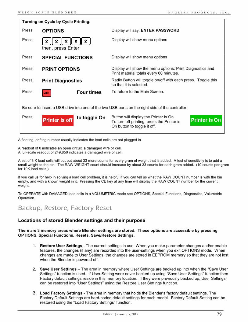
M A G U I R E P R O D U C T S , I N C .
Edition: Janauary 3, 2017 79
W E I G H S C A L E B L E N D E R
Turning on Cycle by Cycle Printing:
Press OPTIONS Display will say: ENTER PASSWORD
Press
then, press Enter
Display will show menu options
Press SPECIAL FUNCTIONS
Display will show menu options
Press PRINT OPTIONS
Display will show the menu options: Print Diagnostics and Print material totals every 60 minutes.
Press Print Diagnostics
Radio Button will toggle on/off with each press. Toggle this so that it is selected.
Press
Four times To return to the Main Screen.
Be sure to insert a USB drive into one of the two USB ports on the right side of the controller. Press
to toggle On Button will display the Printer is On To turn off printing, press the Printer is On button to toggle it off.
A floating, drifting number usually indicates the load cells are not plugged in. A readout of 0 indicates an open circuit, a damaged wire or cell. A full-scale readout of 249,850 indicates a damaged wire or cell. A set of 3 K load cells will put out about 33 more counts for every gram of weight that is added. A test of sensitivity is to add a small weight to the bin. The RAW WEIGHT count should increase by about 33 counts for each gram added. (10 counts per gram for 10K load cells.) If you call us for help in solving a load cell problem, it is helpful if you can tell us what the RAW COUNT number is with the bin empty, and with a known weight in it. Pressing the CE key at any time will display the RAW COUNT number for the current weight. To OPERATE with DAMAGED load cells in a VOLUMETRIC mode see OPTIONS, Special Functions, Diagnostics, Volumetric Operation.
Backup, Restore, Factory Reset Locations of stored Blender settings and their purpose There are 3 memory areas where Blender settings are stored. These options are accessible by pressing OPTIONS, Special Functions, Resets, Save/Restore Settings.
1. Restore User Settings - The current settings in use. When you make parameter changes and/or enable features, the changes (if any) are recorded into the user-settings when you exit OPTIONS mode. When changes are made to User Settings, the changes are stored in EEPROM memory so that they are not lost when the Blender is powered off.
2. Save User Settings – The area in memory where User Settings are backed up into when the “Save User Settings” function is used. If User Setting were never backed up using “Save User Settings” function then Factory default settings reside in this memory location. If they were previously backed up, User Settings can be restored into “User Settings” using the Restore User Settings function.
3. Load Factory Settings - The area in memory that holds the Blender's factory default settings. The Factory Default Settings are hard-coded default settings for each model. Factory Default Setting can be restored using the “Load Factory Settings” function.
M A G U I R E P R O D U C T S , I N C .
Edition: January 3, 2017 80
W E I G H S C A L E B L E N D E R
Updating Controller Firmware Updating the firmware within the Touchscreen Controller can be accomplished through the USB port located on the right side of the controller. USB Drive Software Update
1. This uses a standard USB drive. This method requires a single file supplied by Maguire Products to perform a software update to the Touchscreen Controller. This file may be requested from Maguire Products. The file is labeled (example only):
awb_100708.deb When you are provided with this file, it should be copied to a USB drive in the root directory (not in a sub folder).
2. Insert the USB drive into the USB port on the Touchscreen controller. Note, the controller should be powered on but should not be running cycles.
3. Enter into OPTIONS. Press 22222, then Enter.
4. Press Special Functions, Setup, then Update. The display should show: SOFTWARE UPDATE as well as the Current Version.
5. Press dropdown menu and select the firmware version you want to apply. If more than one firmware version is stored on the flash drive, multiple version will be displayed in the dropdown. If the display says “No Update was found. Please check USB for file.” Then press verify the file is on the USB drive and that it si plugged in. Press Refresh.
6. Highlight the version from the dropdown and Press Select. Display will show: “THE UPDATE IS IN PROGRESS. Please wait…” DO NOT remove flash drive. DO NOT power off controller.
Do not turn off controller or remove the flash drive while firmware is updating! Doing so may corrupt the controller’s firmware.
7. When the display shows The Update Has Completed Successfully, Press <OK> to Run the new
software. Press the OK button. The controller will reboot. After the reboot, the firmware update to the controller is complete.
M A G U I R E P R O D U C T S , I N C .
Edition: Janauary 3, 2017 81
W E I G H S C A L E B L E N D E R
SECTION 5 - HARDWARE MAINTENANCE
Hardware Adjustments
AIR PRESSURE Set AIR PRESSURE to about 80 PSI for best accuracy. However, lower pressures will work.
If you plant air fluctuates, set the regulator to the low end so that the dispense valves always see a consistent pressure. Lubricated air is NOT recommended. Micro Blenders should be set to 40 PSI (2.7 bar). Vertical Valves used in removable hoppers on Micro Blenders, and 100 and 200 series blenders, are more accurate at 60 PSI pressure setting.
LEVEL SENSOR Sensor position; 200 and 400 series models only:
The sensor should protrude into the mix chamber about 1/4 inch past the inside surface of the stainless mounting plate. If it does not protrude far enough, it will sense the mounting plate itself. If it protrudes too far, it will sense the mix blade. Adjusting sensor sensitivity:
1. The adjustment screw is located at the rear of the sensor. It may be protected by a small plastic screw like cover. You will need a very small screwdriver to adjust it.
2. Fill the mix chamber until the sensor is about 3/4 covered. 3. Turn screw counter-clockwise until the LED goes OFF. 4. Then turn clockwise until the LED just goes ON. 5. Empty the chamber and check to be sure the sensor LED does not go on when the
mix blade passes near it.
WEIGH BIN DUMP VALVE The WEIGH BIN DUMP VALVE should be adjusted to close softly. A needle valve is
installed next to the quick disconnect so that air flow to the flap air cylinder may be restricted. Adjust as required for a soft close.
SLIDE VALVES Slide valves must move very freely. If they seem to jam slightly as they reach the full
extended position (closed), this may be due to the air cylinder mount being slightly bent. If someone has pulled down or pushed up on the air cylinder, they may have bent the cylinder mount. You can correct this by pressing up or down on the cylinder as required to correct the problem. If you process very hard pellets (polycarbonate and glass filled resins), your slide gate dispense valves may stick closed occasionally. We provide spacers that limit the full stoke of the air cylinder. This stops the slide from going any further then the just closed position and prevents jamming. Call us for information.
INTERNAL MIX MOTOR and AUGER FEEDER FUSES The MIX MOTOR timed power source and the AUGER FEEDER OUTLETS are driven by
internal solid state plug-in relays. A small 5 amp glass fuse is located to the right of each relay. A spare fuse is also located on the board if replacement is necessary.
M A G U I R E P R O D U C T S , I N C .
Edition: January 3, 2017 82
W E I G H S C A L E B L E N D E R
Load Cell Recalibration This unit was properly calibrated at the factory to match the load cells that were supplied with it. If you are going to recalibrate, note the following. The proper sequence is given below. BE SURE the load cell plug is plugged into the side of the controller. BE SURE the weigh bin is hanging from the load cells freely. BE SURE the air line to the dump valve is connected as it would be
during normal operation. (A disconnected air line adds weight.) Air pressure to the line is not necessary.
BE SURE there is nothing touching the weigh bin or air line. BE SURE the bin is EMPTY when ZEROING the load cells. ZERO WT. must be done before FULL WT. Since changes in ZERO WT will also shift the FULL WT scale by the same amount, it may not be necessary to go any farther than this. When SETTING FULL WEIGHT, BE SURE you know the exact weight (in GRAMS) that you are adding to the bin. Place this weight in the bin and then press the FULL WT. key. Five dashes (FUL-----) will be displayed. Enter the EXACT weight in GRAMS that you have placed in the bin. The weight should be close to the designed full bin weight; (400, 1000, 2000, 4000, 9000, or 18000).
Load Cell Recalibration:
Press OPTIONS Display will say: ENTER PASSWORD
Press
then, press Enter
Display will show menu options
Press SPECIAL FUNCTIONS
Display will show menu options
Press SETUP
Display will show menu options
Press Calibrate Load Cells
Display will show: Calibrate load cells and a “SET ZERO WT” button.
Press SET ZERO WT Confirm weigh bin is empty. Press the DUMP BIN button to dump any material out of the weigh bin. When bin is confirmed empty, press Yes.
Display Wait while calibrating load cells. Do not touch weigh bin during calibration. After zero calibration has completed successfully press OK.
Press SET FULL WT Display will show a keypad and the message: Enter the known weight and then press enter. Enter your known weight in GRAMS and then press enter.
Place the known weight in the weigh bin and then properly re-install the weigh bin into the blender. Press CONTINUE to proceed. Display Wait while calibrating load cells. Do not touch weigh bin during calibration.
After Full calibration has proceeded successfully, you will be prompted.
Press Ok to complete the calibration. Press EXIT three times to exit out of SETUP.
After FULL weight calibration, if the display says BAD LOAD CELL, then the weight you are using does not match the weight you entered, the weigh bin is not free to move, OR the load cells are bad.
M A G U I R E P R O D U C T S , I N C .
Edition: Janauary 3, 2017 83
W E I G H S C A L E B L E N D E R
BLENDER PREVENTIVE MAINTENANCE There are no components of your blender that require periodic maintenance. However, over the years, blenders may be subjected to abuse or difficult conditions, and accuracy can suffer. To maintain control over the cost of expensive color and additives, you must maintain accuracy. We recommend that blenders be examined once a year, and all necessary repairs be made to insure continued accuracy. DISPENSE GATES To be accurate, gates must open and close freely, quickly, and completely. Check for wear on the
slide gate guide rods. Check cylinder clevis adjustment for correct closing of the gate. A gate should close just enough to block the hole, but no further. It is best if they do not pass over the far edge of the opening as this might catch and jam on a pellet. Check that the clevis pin connecting the air cylinder is intact, not broken or worn through. Check for correct air pressure, tight fittings, and no damaged or crimped air lines.
WEIGH BINS Check for smooth correct operation of the dump flap. Hinge points should not be worn. Gate should
overlap the forward edge enough to prevent dribble when closed, even when closed against pellets. Space at the rear of the flap should allow for static build up of pellets on the rear edge of the dump flap without interfering with the closing of the flap. Again, if you see evidence of these problems, newer design parts are available to solve these problems. Check that the flap closes fully, and closes softly. The soft close is adjustable.
CLEARANCES - FREE MOVEMENT OF WEIGH BIN Carefully examine all the parts of the weigh bin and the bin hanging bracket to be sure that nothing
touches any fixed parts. A quarter (1/4) inch of space should exist on all sides of the weigh bin. Over the years, windows and guards have been added, and this has required that the weigh bin size be reduced to maintain 1/4 inch clearance per side. Be sure you do not have an older larger bin installed where windows have been added. A light touch of the bin should show a change in the weight readout. Remove the touch and the display should return to exactly the same number, plus or minus 1 or 1/10 gram depending on model. Only the last digit should drift, or vary, and by no more then one count. If ANY interference is detected, it MUST be fixed.
MIX CHAMBER No bent blades. No SHARP blades. Bent blades might brake off and severally damage your process
screw. Sharp blades are a safety hazard. Replace if mix blades are not perfect. The blade assembly should slip on and off the motor shaft easily. The need to use excessive force to remove the mixer assembly may bend the blades and they may eventually break off. Correct this if it is a problem.
PRINT DIAGNOSTICS, PRINT PARAMETERS PRINTOUTS After you have fixed any problems, use the Print Diagnostics and Print Parameters print options to
obtain printouts and fax or email them to us for evaluation.
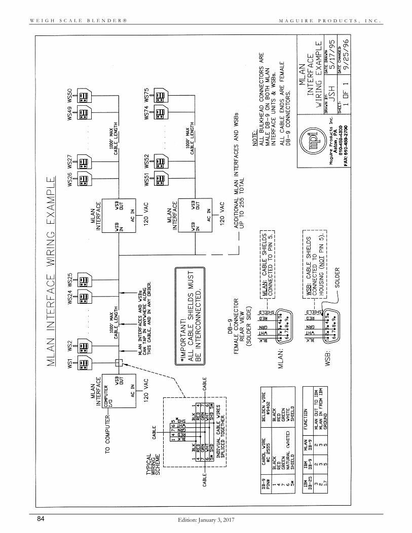
M A G U I R E P R O D U C T S , I N C .
Edition: January 3, 2017 84
W E I G H S C A L E B L E N D E R
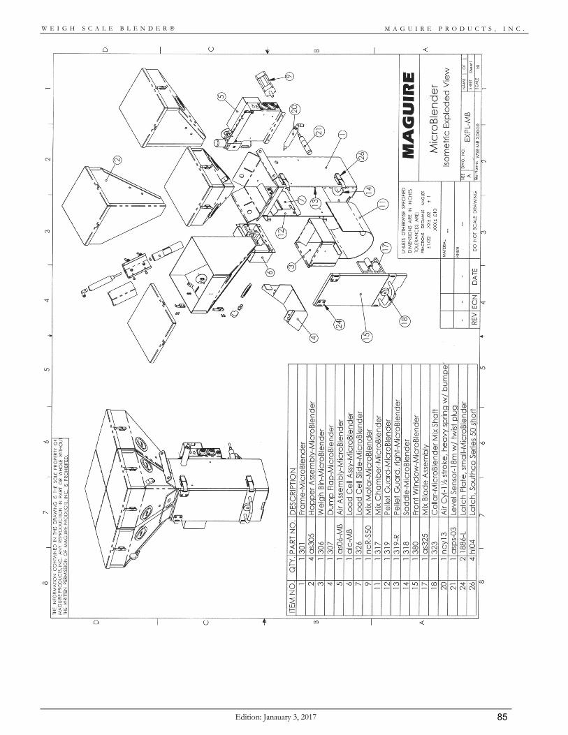
M A G U I R E P R O D U C T S , I N C .
Edition: Janauary 3, 2017 85
W E I G H S C A L E B L E N D E R
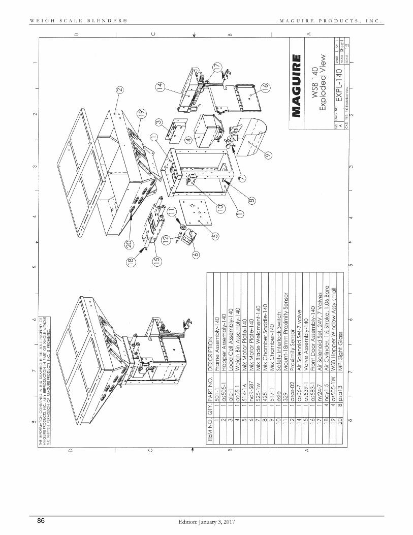
M A G U I R E P R O D U C T S , I N C .
Edition: January 3, 2017 86
W E I G H S C A L E B L E N D E R
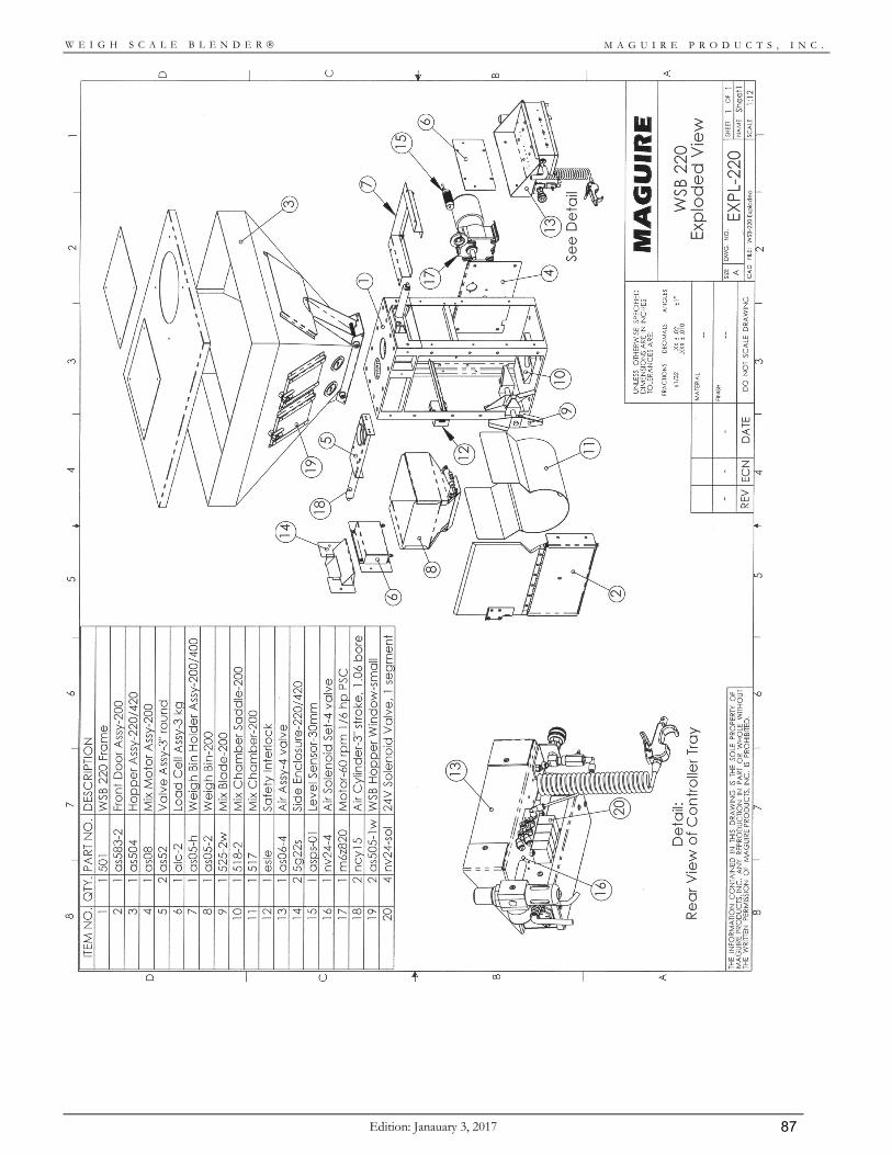
M A G U I R E P R O D U C T S , I N C .
Edition: Janauary 3, 2017 87
W E I G H S C A L E B L E N D E R
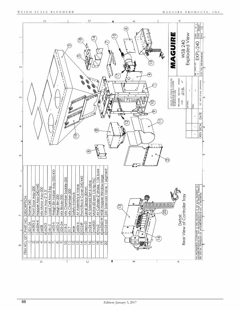
M A G U I R E P R O D U C T S , I N C .
Edition: January 3, 2017 88
W E I G H S C A L E B L E N D E R
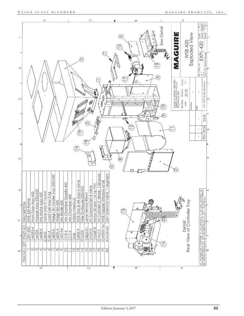
M A G U I R E P R O D U C T S , I N C .
Edition: Janauary 3, 2017 89
W E I G H S C A L E B L E N D E R
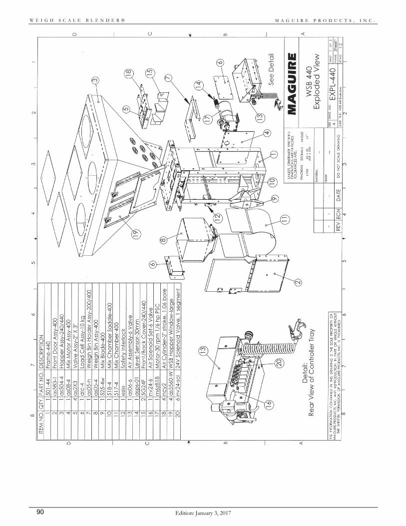
M A G U I R E P R O D U C T S , I N C .
Edition: January 3, 2017 90
W E I G H S C A L E B L E N D E R
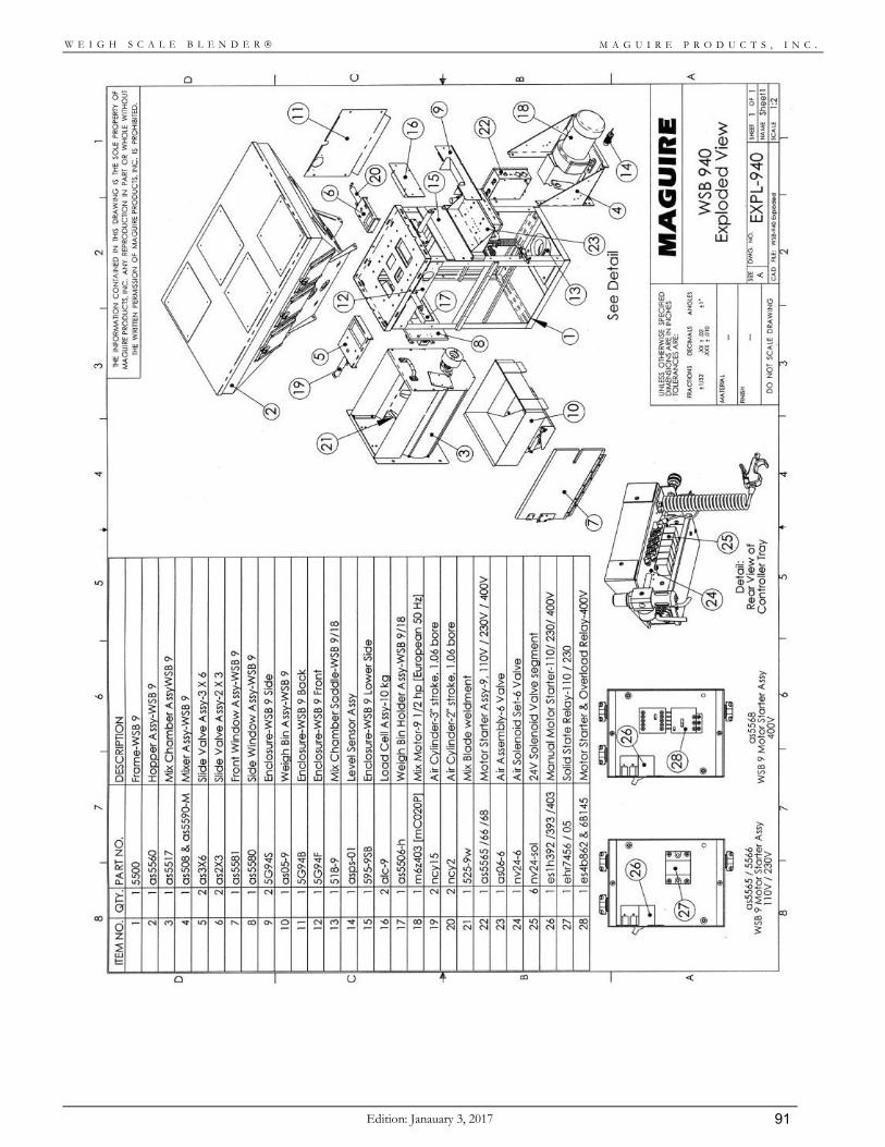
M A G U I R E P R O D U C T S , I N C .
Edition: Janauary 3, 2017 91
W E I G H S C A L E B L E N D E R
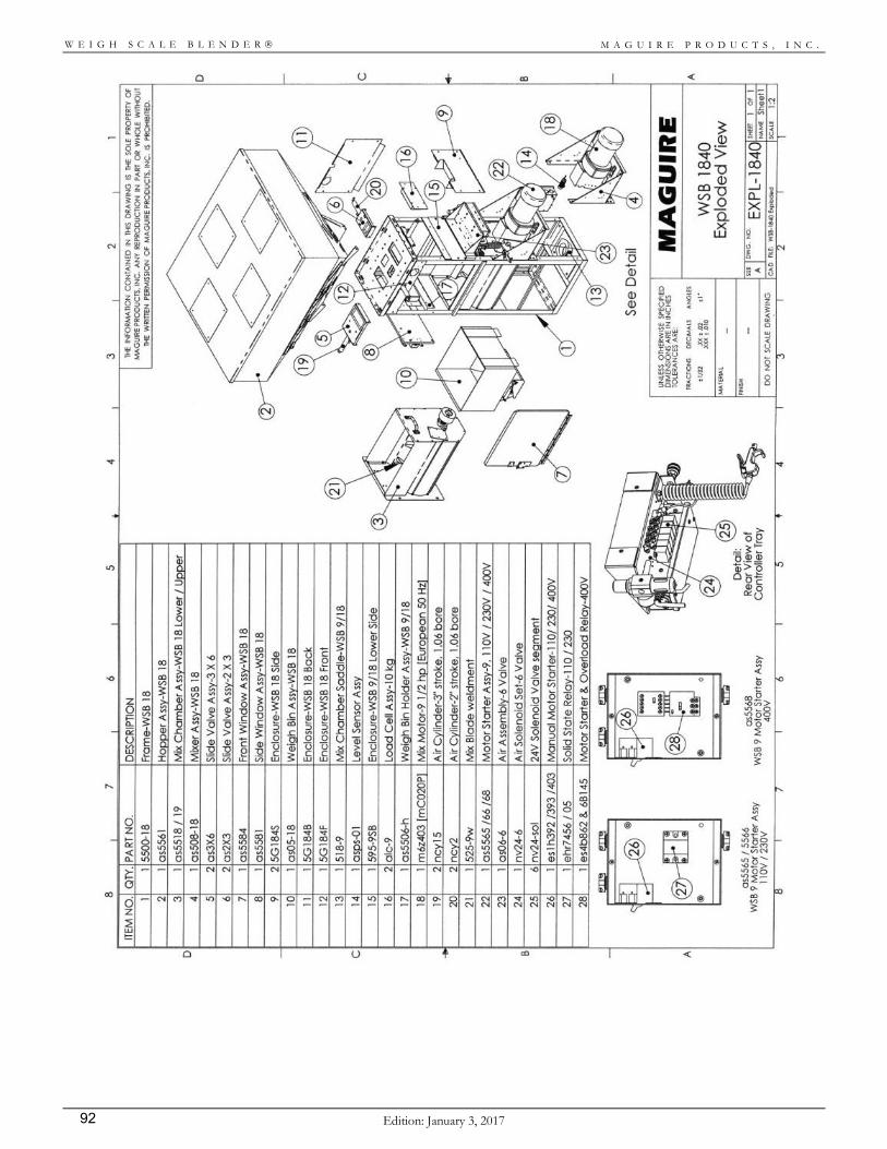
M A G U I R E P R O D U C T S , I N C .
Edition: January 3, 2017 92
W E I G H S C A L E B L E N D E R
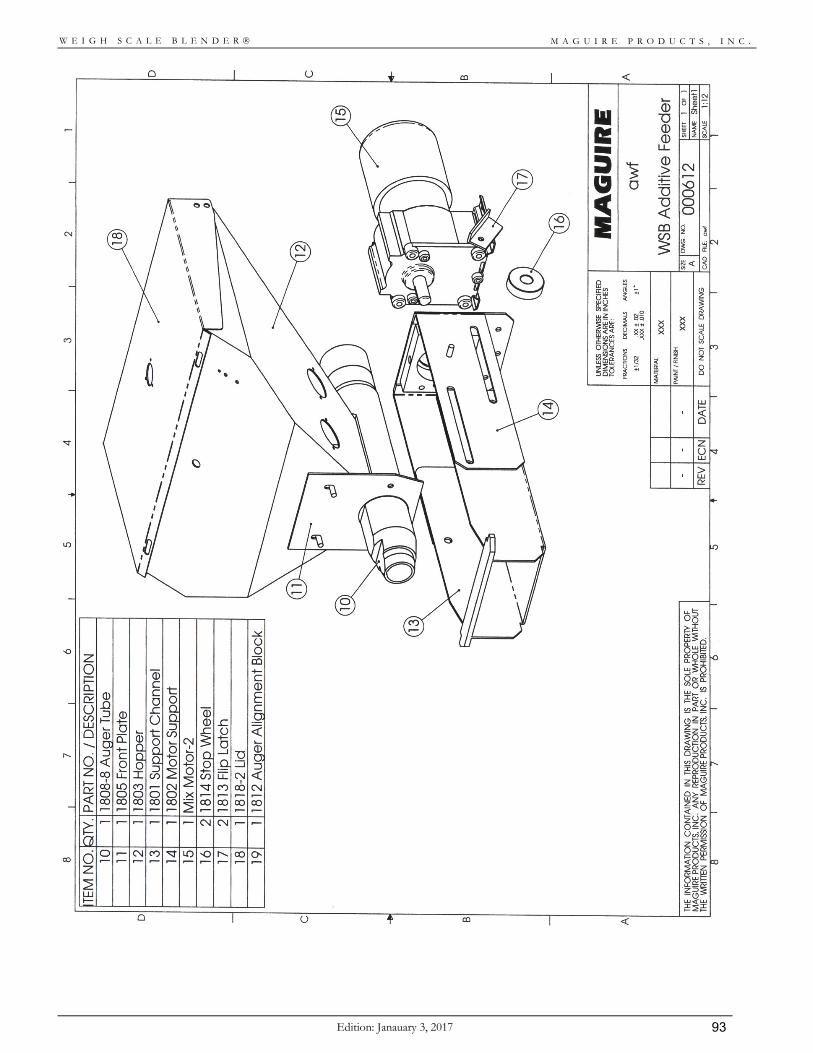
M A G U I R E P R O D U C T S , I N C .
Edition: Janauary 3, 2017 93
W E I G H S C A L E B L E N D E R
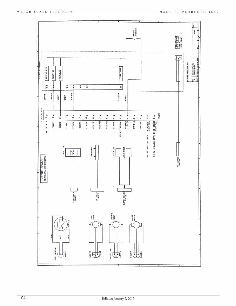
M A G U I R E P R O D U C T S , I N C .
Edition: January 3, 2017 94
W E I G H S C A L E B L E N D E R
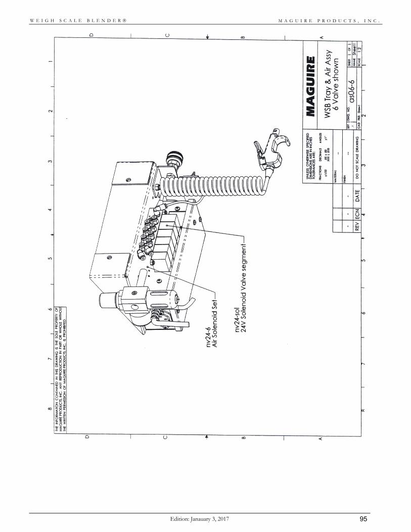
M A G U I R E P R O D U C T S , I N C .
Edition: Janauary 3, 2017 95
W E I G H S C A L E B L E N D E R
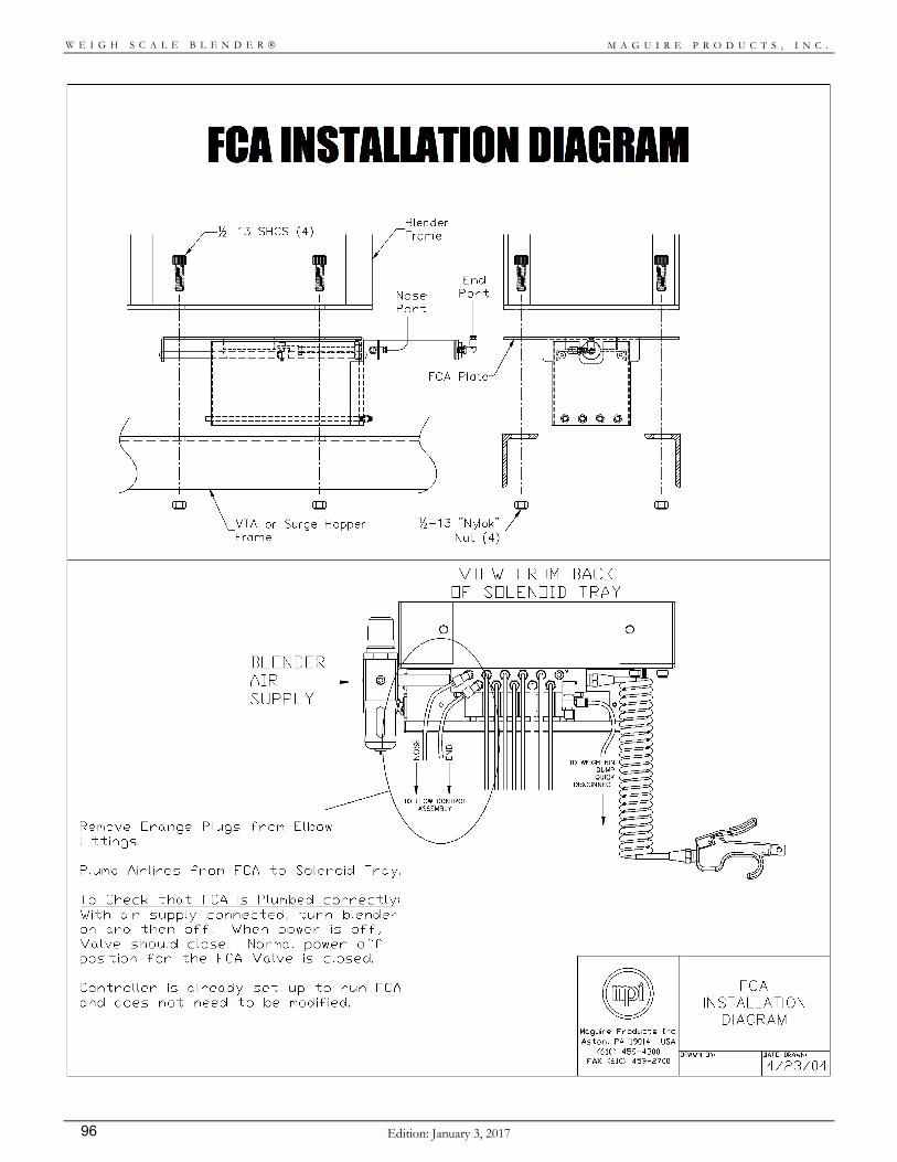
M A G U I R E P R O D U C T S , I N C .
Edition: January 3, 2017 96
W E I G H S C A L E B L E N D E R
M A G U I R E P R O D U C T S , I N C .
Edition: Janauary 3, 2017 97
W E I G H S C A L E B L E N D E R
Disclaimers
Production of Faulty Product
Processing conditions and materials vary widely from customer to customer and from product to product. It is IMPOSSIBLE for us to anticipate ALL processing conditions and requirements, or to be certain that our equipment will perform properly in all instances. You, the customer, must observe and verify the performance level of our equipment in your plant as part of your overall manufacturing process. You must verify to your own satisfaction that this level of performance meets your requirements. We CAN NOT be responsible for losses due to product that is blended incorrectly, even when due to equipment malfunction or design incorrect for your requirements; and/or for any consequential losses due to our equipment not blending to your requirements. We will only be responsible to correct, repair, replace, or accept return for full refund if our equipment fails to perform as designed, or we have inadvertently misrepresented our equipment for your application.
Accuracy of this Manual
We make every effort to keep this manual as correct and current as possible. However, technology and product changes occur more rapidly then the reprinting of this manual. Generally, modifications made to the design of the blender or to the operation of the software are not reflected in the manual for 3 to 6 months. We always reserve the right to make these changes without notice, and we do not guarantee the manual to be entirely accurate. If you question any information in this manual, or find errors, please let us know so that we may make the required corrections. We will gladly provide you with updated manuals.

M A G U I R E P R O D U C T S , I N C .
Edition: January 3, 2017 98
W E I G H S C A L E B L E N D E R
Warranty – Exclusive 5-Year MAGUIRE PRODUCTS offers THE MOST COMPREHENSIVE WARRANTY in the plastics equipment industry. We warrant each Weigh Scale Blender manufactured by us to be free from defects in material and workmanship under normal use and service; excluding only those items listed below as 'excluded items'; our obligation under this warranty being limited to making good at our factory any Weigh Scale Blender which shall within FIVE (5) YEARS after delivery to the original purchaser be RETURNED intact to us, transportation charges PREPAID, and which our examination shall disclose to our satisfaction to have been thus defective; this warranty being expressly in lieu of all other warranties expressed or implied and of all other obligations or liabilities on our part, and MAGUIRE PRODUCTS neither assumes nor authorizes any other persons to assume for it any other liability in connection with the sale of its Weigh Scale Blenders. This warranty shall not apply to any Weigh Scale Blender, which shall have been repaired or altered outside MAGUIRE PRODUCTS factory, unless such repair or alteration was, in our judgment, not responsible for the failure; nor which has been subject to misuse, negligence or accident, incorrect wiring by others, or installation or use not in accord with instructions furnished by Maguire Products. Our liability under this warranty will extend ONLY to equipment that is returned to our factory in Aston, Pennsylvania, PREPAID. Please note that we always strive to satisfy our customers in whatever manner is deemed most expedient to overcome any problems they may have in connection with our equipment. EXCLUDED ITEMS: LOAD CELLS on our WEIGH SCALE BLENDER are covered as long as they have not been damaged from improper handling. MB, 100, and 200 series units use load cells rated for 6.6 pounds (3KG) maximum load. Larger units use load cells rated for 22 pounds (10KG). DO NOT press on them manually. DO NOT disassemble them from their mounting enclosures. Do not DROP then. Do not drop the frame to which they are mounted. If the frame is dropped from a height of two feet, the load cells will most likely be damaged. DISCLAIMER: Processing conditions and materials vary widely from customer to customer and from product to product. Please be aware that it is IMPOSSIBLE for us to anticipate ALL processing conditions and requirements, or to be certain that our equipment will perform properly in all instances. You, the customer, must observe and verify the performance level of our equipment in your plant as part of your overall manufacturing process. You must verify to your own satisfaction that this level of performance meets your requirements. We CAN NOT be responsible for losses due to product that is blended incorrectly, even when due to equipment malfunction or design incorrect for your requirements; and/or for any consequential losses due to our equipment not blending to your requirements.
We will only be responsible to correct, repair, replace, or accept return for full refund if we have inadvertently misrepresented our equipment for your application.

M A G U I R E P R O D U C T S , I N C .
Edition: Janauary 3, 2017 99
W E I G H S C A L E B L E N D E R
Technical Support and Contact Information
Maguire Products Inc. 11 Crozerville Road Aston, PA 19014 Tel: 610.459.4300 Fax: 610.459.2700 Email: [email protected] Web: www.maguire.com Maguire Europe Tame Park Tamworth Staffordshire B775DY UK Tel: + 44 1827 265 850 Fax: + 44 1827 265 855 Email: [email protected] Maguire Products Asia PTE LTD Main Office 15 Changi North Street 1 #01-15, I-Lofts Singapore 498765 Tel: 65 6848-7117 Fax: 65 6542-8577 E-mail: [email protected]