Embed Size (px)
Citation preview
Application description
Application description
Page 1/141Order no. 7574 01 01 6T8736 52a
Displays
Berker
Hersteller
Touch Displays
Touch ControlETS
KNX Touch Control
Order number Product designation Application
programme TP product
7574 01 01 KNX Touch Control
S7574 0101
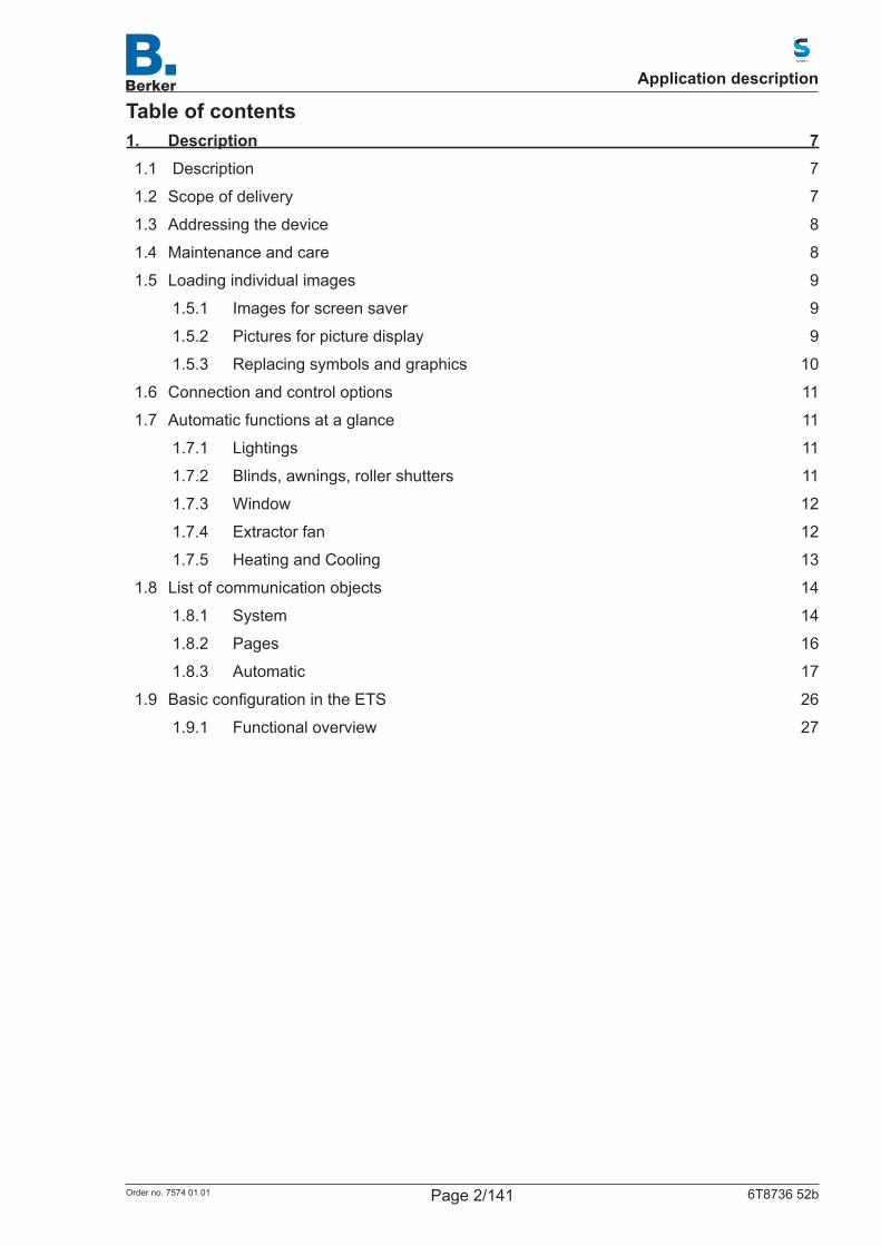
Table of contents1. Description 71.1 Description 7
1.2 Scope of delivery 7
1.3 Addressing the device 8
1.4 Maintenance and care 8
1.5 Loading individual images 9
1.5.1 Images for screen saver 9
1.5.2 Pictures for picture display 9
1.5.3 Replacing symbols and graphics 10
1.6 Connection and control options 11
1.7 Automatic functions at a glance 11
1.7.1 Lightings 11
1.7.2 Blinds, awnings, roller shutters 11
1.7.3 Window 12
1.7.4 Extractor fan 12
1.7.5 Heating and Cooling 13
1.8 List of communication objects 14
1.8.1 System 14
1.8.2 Pages 16
1.8.3 Automatic 17
1.9 BasicconfigurationintheETS 26
1.9.1 Functional overview 27
Application description
Page 2/141Order no. 7574 01 01 6T8736 52b
2. System language selection 282.1 Object control 28
2.2 Adjustment on the display 28
2.3 Adjustment via the ETS 28
3. Language of the editable texts 293.1 Object control 29
3.2 Adjustment on the display 29
3.3 Adjustment via the ETS 29
4. Display 314.1 Object control 31
4.2 Adjustment on the display 31
4.3 Adjustment via the ETS 32
5. Button sound 345.1 Object control 34
5.2 Adjustment on the display 34
5.3 Adjustment via the ETS 34
6. Proximity sensor 357. Alarm 368. Weekly timer 378.1 Timer function 1 ... 16 37
9. Alarm clock 399.1 Object control 39
9.2 Adjustment on the display 39
9.3 Adjustment via the ETS 40
10. Service 4111. Set system on the display 4211.1 Access codes for display menus 43
11.2 System language selection 43
11.3 Language of the editable texts 44
11.4 Display 45
11.4.1 Cleaning mode 45
11.4.2 Display options 45
11.4.3 Brightness 46
11.4.4 Screen saver 47
11.4.5 Start page 49
11.4.6 Do not touch action 49
Application description
Page 3/141Order no. 7574 01 01 6T8736 52b
11.5 Button sound 50
11.6 Alarm 51
11.7 Timer 53
11.8 Alarm clock 55
11.9 Service 58
11.9.1 Resetting access code 58
11.9.2 Resetting device to last ETS download 58
11.9.3 Resetting the device 58
11.9.4 Addressing the device 58
11.9.5 Info 58
11.9.6 Licence 58
12. Configurationofdisplaypages 5912.1 Selecting pages on the display 59
12.2ConfigurationofpagesintheETS 60
12.2.1 Surface 61
12.2.2 Rocker 63
12.2.3 Rotary control 65
12.3 Overviewofpredefinedpages 68
12.4 Overview symbols 73
13. Automatic functions 8013.1 Safety instructions regarding automatic functions 80
13.2 General automatic settings 80
13.2.1 Settings for position of the sun 81
13.2.2 Wind and Rain Alarm 84
13.2.3 Twilight 84
13.2.4 Movement delays 84
13.2.5 Window opening restriction 85
13.2.6 Ventilation lock-up 85
13.2.7 Night-time re-cooling 85
13.2.8 Frost alarm 85
13.2.9 Heat protection 86
13.2.10 Automatic reset 86
13.3 Automatic light control 87
13.4 Automatic shading (blind, awning, roller shutter) 89
13.4.1 Automatic lock-up and safety 89
13.4.2 Priorities of the automatic shading 90
13.4.3 Setting shading 90
13.4.4 Angle of the direction of the sun 95
Application description
Page 4/141Order no. 7574 01 01 6T8736 52b
13.5 Automatic window 96
13.5.1 Automatic lock-up and safety 96
13.5.2 Priorities of the automatic window 97
13.5.3 Setting window ventilation 98
13.6 Automatic fan 101
13.6.1 Automatic lock-up and safety 101
13.6.2 Priorities of the automatic fan 102
14. Automatic temperature control 10514.1 Regulation general 105
14.2 Setpoints 107
14.2.1 Setpoint comfort 108
14.2.2 Setpoint standby 108
14.2.3 Setpoint night reduction 108
14.2.4 Setpoints frost/heat protection (building protection) 109
14.3 Heating control and valve position 110
14.3.1 Valve positions general 110
14.3.2 Heating control level 111
14.3.3 Heating control background and supplementary level 112
14.3.3.12-point control 112
14.3.4 Cooling control level 114
14.3.5 Cooling control background and supplementary level 115
14.3.5.12-point control 115
15. Additional settings (ETS) 11715.1 Interfaces 117
15.1.1 Function as switch 117
15.1.2 Function as toggle switch 118
15.1.3 Settings for blind, roller shutter, awning, or window control 118
15.1.3.1Function as blind control 118
15.1.3.2Function as roller shutter control 119
15.1.3.3Function as awning control 120
15.1.3.4Function as window control 121
15.1.3.5Control mode for drive control 122
15.1.4 Function as dimmer 123
15.1.5 Function as 8-bit value transmitter 123
15.1.6 Function as 16-bit value transmitter 123
15.1.7 Function as scene control 123
15.1.8 Temperature sensor (NTC) 124
Application description
Page 5/141Order no. 7574 01 01 6T8736 52b
15.2 Temperature limit 125
15.2.1 Setting temperature limit 1 - 4 125
15.2.2 ON/OFF output 126
15.2.3 Lock-up 127
15.3 Scene control 128
15.3.1 Scene object 1-16 128
15.4 Logic (ETS) 129
15.4.1 AND Logic 1/2/3/4 and OR Logic 1/2/3/4 130
15.4.1.1Lock-up 131
16. Appendix 13316.1 Table of the logic function 133
16.2 Characteristics 134
16.3 Technical data 134
16.4 Accessories 134
16.5 Warranty 134
Application description
Page 6/141Order no. 7574 01 01 6T8736 52b
1. Description
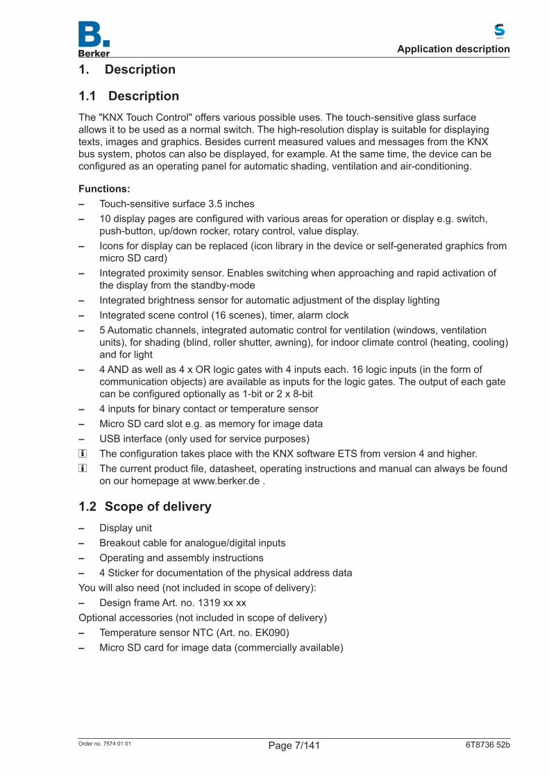
1.1 DescriptionThe "KNX Touch Control" offers various possible uses. The touch-sensitive glass surface allows it to be used as a normal switch. The high-resolution display is suitable for displaying texts, images and graphics. Besides current measured values and messages from the KNX bus system, photos can also be displayed, for example. At the same time, the device can be configuredasanoperatingpanelforautomaticshading,ventilationandair-conditioning.
Functions: – Touch-sensitive surface 3.5 inches – 10displaypagesareconfiguredwithvariousareasforoperationordisplaye.g.switch,
push-button, up/down rocker, rotary control, value display. – Icons for display can be replaced (icon library in the device or self-generated graphics from
micro SD card) – Integrated proximity sensor. Enables switching when approaching and rapid activation of
the display from the standby-mode – Integrated brightness sensor for automatic adjustment of the display lighting – Integrated scene control (16 scenes), timer, alarm clock – 5 Automatic channels, integrated automatic control for ventilation (windows, ventilation
units), for shading (blind, roller shutter, awning), for indoor climate control (heating, cooling) and for light
– 4 AND as well as 4 x OR logic gates with 4 inputs each. 16 logic inputs (in the form of communication objects) are available as inputs for the logic gates. The output of each gate canbeconfiguredoptionallyas1-bitor2x8-bit
– 4 inputs for binary contact or temperature sensor – Micro SD card slot e.g. as memory for image data – USB interface (only used for service purposes) TheconfigurationtakesplacewiththeKNXsoftwareETSfromversion4andhigher. Thecurrentproductfile,datasheet,operatinginstructionsandmanualcanalwaysbefound
on our homepage at www.berker.de .
1.2 Scope of delivery – Display unit – Breakout cable for analogue/digital inputs – Operating and assembly instructions – 4 Sticker for documentation of the physical address data
You will also need (not included in scope of delivery): – Design frame Art. no. 1319 xx xx
Optional accessories (not included in scope of delivery) – Temperature sensor NTC (Art. no. EK090) – Micro SD card for image data (commercially available)
Application description
Page 7/141Order no. 7574 01 01 6T8736 52b

1.3 Addressing the deviceThe programming mode for physical addressing can be carried out via the programming button at the back of the device or via the display. For this purpose, you need to make the following settings on the display:
Settings → System → Service → KNX
KNX-PROG LED
KNX Phys. Address: 1.1.1
OFF
Settings System Service KNX
KNX programming LED ON:Programming mode active.
KNX programming LED OFF:Programming mode off.
The current address is displayed.Address in default state: 15.15.250
Figure 1: Programming physical address
1.4 Maintenance and careYoucanbestremovefingerprintsontheglasssurfaceusingadampclothormicrofibrecloth.
Do not use any abrasive / cleaning agents or aggressive care products for cleaning.The "cleaning mode" is available for cleaning the screen, which is activated via the display.
Settings → Cleaning modeThe operation of the touch-sensitive control surface will then be blocked for a duration preset in the ETS and the display can be cleaned.
Cleaning mode
System
Settings
00:00:42
Figure 2: Cleaning mode
Application description
Page 8/141Order no. 7574 01 01 6T8736 52b
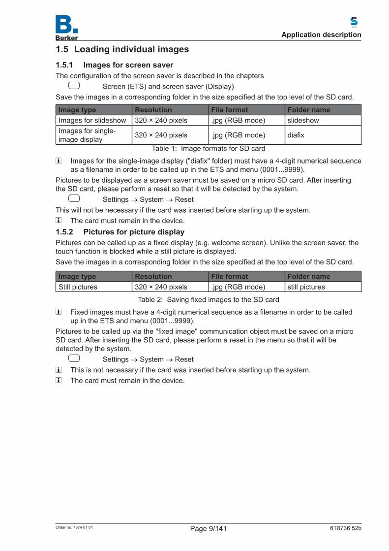
1.5 Loading individual images1.5.1 Images for screen saverTheconfigurationofthescreensaverisdescribedinthechapters
Screen (ETS) and screen saver (Display)SavetheimagesinacorrespondingfolderinthesizespecifiedatthetopleveloftheSDcard.
Image type Resolution File format Folder nameImages for slideshow 320 × 240 pixels .jpg (RGB mode) slideshowImages for single-image display 320 × 240 pixels .jpg (RGB mode) diafix
Table 1: Image formats for SD card
Imagesforthesingle-imagedisplay("diafix"folder)musthavea4-digitnumericalsequenceasafilenameinordertobecalledupintheETSandmenu(0001...9999).
Pictures to be displayed as a screen saver must be saved on a micro SD card. After inserting the SD card, please perform a reset so that it will be detected by the system.
Settings → System → Reset This will not be necessary if the card was inserted before starting up the system.
The card must remain in the device.1.5.2 Pictures for picture displayPicturescanbecalledupasafixeddisplay(e.g.welcomescreen).Unlikethescreensaver,thetouch function is blocked while a still picture is displayed.SavetheimagesinacorrespondingfolderinthesizespecifiedatthetopleveloftheSDcard.
Image type Resolution File format Folder nameStill pictures 320 × 240 pixels .jpg (RGB mode) still pictures
Table 2: SavingfixedimagestotheSDcard
Fixedimagesmusthavea4-digitnumericalsequenceasafilenameinordertobecalledup in the ETS and menu (0001...9999).
Picturestobecalledupviathe"fixedimage"communicationobjectmustbesavedonamicroSD card. After inserting the SD card, please perform a reset in the menu so that it will be detected by the system.
Settings → System → Reset This is not necessary if the card was inserted before starting up the system. The card must remain in the device.
Application description
Page 9/141Order no. 7574 01 01 6T8736 52b
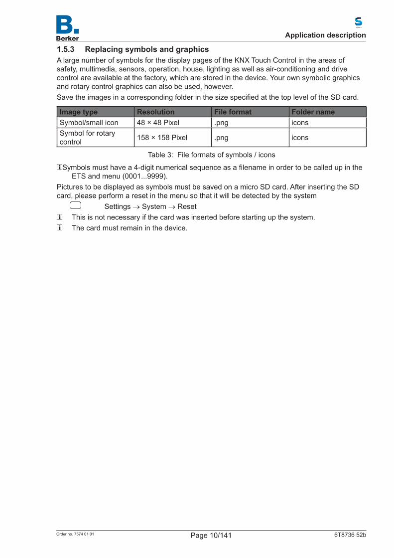
1.5.3 Replacing symbols and graphicsA large number of symbols for the display pages of the KNX Touch Control in the areas of safety, multimedia, sensors, operation, house, lighting as well as air-conditioning and drive control are available at the factory, which are stored in the device. Your own symbolic graphics and rotary control graphics can also be used, however.SavetheimagesinacorrespondingfolderinthesizespecifiedatthetopleveloftheSDcard.
Image type Resolution File format Folder nameSymbol/small icon 48 × 48 Pixel .png iconsSymbol for rotary control 158 × 158 Pixel .png icons
Table 3: File formats of symbols / icons
Symbolsmusthavea4-digitnumericalsequenceasafilenameinordertobecalledupintheETS and menu (0001...9999).
Pictures to be displayed as symbols must be saved on a micro SD card. After inserting the SD card, please perform a reset in the menu so that it will be detected by the system
Settings → System → Reset This is not necessary if the card was inserted before starting up the system. The card must remain in the device.
Application description
Page 10/141Order no. 7574 01 01 6T8736 52b
1.6 Connection and control optionsVarious environmental parameters/measured values have to be provided via the bus for the automatic control of shading, ventilation etc. In chapter 13.2 General automatic settings the necessary parameters are described for the individual automatic functions.A temperature sensor for detecting the room temperature can also be connected directly to one of the 4 analog/digital inputs of the device. Furthermore, for example, conventional push-buttons, switches and window contacts can be connected to these inputs.Date and time should be received periodically at least once per day via the bus (object no. 8+9).Dateandtimearerequiredwiththeobjectno.10.Theinternalclockofthedevicehasamaximum Fehlgang of ± 3 seconds per day. The alarm clock of the KNX Touch Control will only function after the time has been received from the bus.
1.7 Automatic functions at a glanceThedevicehasfiveautomaticchannelsthatcanbeassignedthefunctionslighting,awning,blind, roller shutter, window, ventilation unit and temperature control (heating/cooling).
Basic tips: – For the time-dependent retraction of blinds/roller shutters/awnings the entire running time is
executed (no position is approached) – The approaching of positions is only adjustable for shading and ventilation
1.7.1 LightingsThefollowingenvironmentalparameters/measuredvaluesarerequiredforthecontroloflighting. – Brightness – time
In addition to the settings lighting can be controlled via automatic functions – Switching or dimming. The brightness value for ON/OFF is adjustable when dimming – Switching on at night and during certain periods. Both can also be linked (AND/OR).
The twilight value is adjustable – Automatic reset (time point/time periods adjustable)
1.7.2 Blinds, awnings, roller shuttersThefollowingenvironmentalparameters/measuredvaluesarerequiredforthecontrolofblinds,awnings or shutters. – Brightness – Position of the sun – Outdoor Temperature – Indoor Temperature – Wind speed – Precipitation message – time
In addition to the settings blinds, roller shutters or awnings can be controlled via automatic functions
– Shading according to brightness and position of the sun (sun elevation/direction) – or always (visual protection, i.e. only change the slat position and movement position) – or never (only time-dependent retraction, rain, wind and frost protection) – Position and slat position are adjustable in two stages. Slat tracking according to sun
elevation is possible – Movement delays for extending/retracting adjustable – Night-time closure
Application description
Page 11/141Order no. 7574 01 01 6T8736 52b
– Time-dependent retraction – Room temperature lock-up: Leave open until set room temperature is reached – Outsidetemperaturelock-up:Shadingfirstaboveasetoutsidetemperature – Heat protection (approach alternative position) – Frost protection (retract if precipitation is below a set outside temperature) – Wind protection (retract if a set wind speed is exceeded) – Rain protection (retract if precipitation) – Automatic reset (time point/time periods adjustable)
1.7.3 WindowThefollowingenvironmentalparameters/measuredvaluesarerequiredforthecontrolofwindows. – Outdoor Temperature – Indoor Temperature – Indoor humidity – CO2 content of the indoor air – Wind speed – Precipitation message – time
In addition to the settings windows can be controlled via automatic functions – Opening stages with up to 10 steps – Movement position/Opening restriction – Ventilate according to room temperature, humidity and CO2-content of the indoor air – Outside temperature lock-up: Lock-up below a set outside temperature – Frost protection: Close if precipitation is below a set outside temperature – Close if supply air temperature is higher than room temperature – Rain protection: If precipitation, close or close up to one gap – Wind protection: Close if a set wind speed is exceeded – Timed ventilation, timed closing – Night-time re-cooling (time period, room temperature and window opening adjustable) – Automatic reset (time point/time periods adjustable)
1.7.4 Extractor fanThefollowingenvironmentalparameters/measuredvaluesarerequiredforthecontroloffans. – Outdoor Temperature – Indoor Temperature – Indoor humidity – CO2 content of the indoor air – time
In addition to the settings ventilation can be controlled via automatic functions – Speed range adjustable – Ventilate according to room temperature, humidity and CO2-content of the indoor air – Outside temperature lock-up: Lock-up below a set outside temperature – Do not ventilate if supply air temperature is higher than room temperature – Timed ventilation – Night-time re-cooling (time period, room temperature and fan speed adjustable) – Automatic reset (time point/time periods adjustable)
Application description
Page 12/141Order no. 7574 01 01 6T8736 52b
1.7.5 Heating and CoolingThefollowingenvironmentalparameters/measuredvaluesarerequiredforthecontrolofheatersand cooling devices. – Indoor temperature
In addition to the settings heating and cooling can be controlled via automatic functions – Heating and cooling in two stages, 1st stage PI control, 2nd stage PI control or 2-point
control – Values for the comfort, standby, night reduction and frost/heat protection mode can be
adjusted separately or the comfort value is used as a basis – Change-over between heating and cooling by means of dead zone or changeover object – Dayextension(nightreductioncanbedeactivatedbriefly) – Frost protection (setpoint and activation delay adjustable) – Heat protection (setpoint and activation delay adjustable)
Application description
Page 13/141Order no. 7574 01 01 6T8736 52b
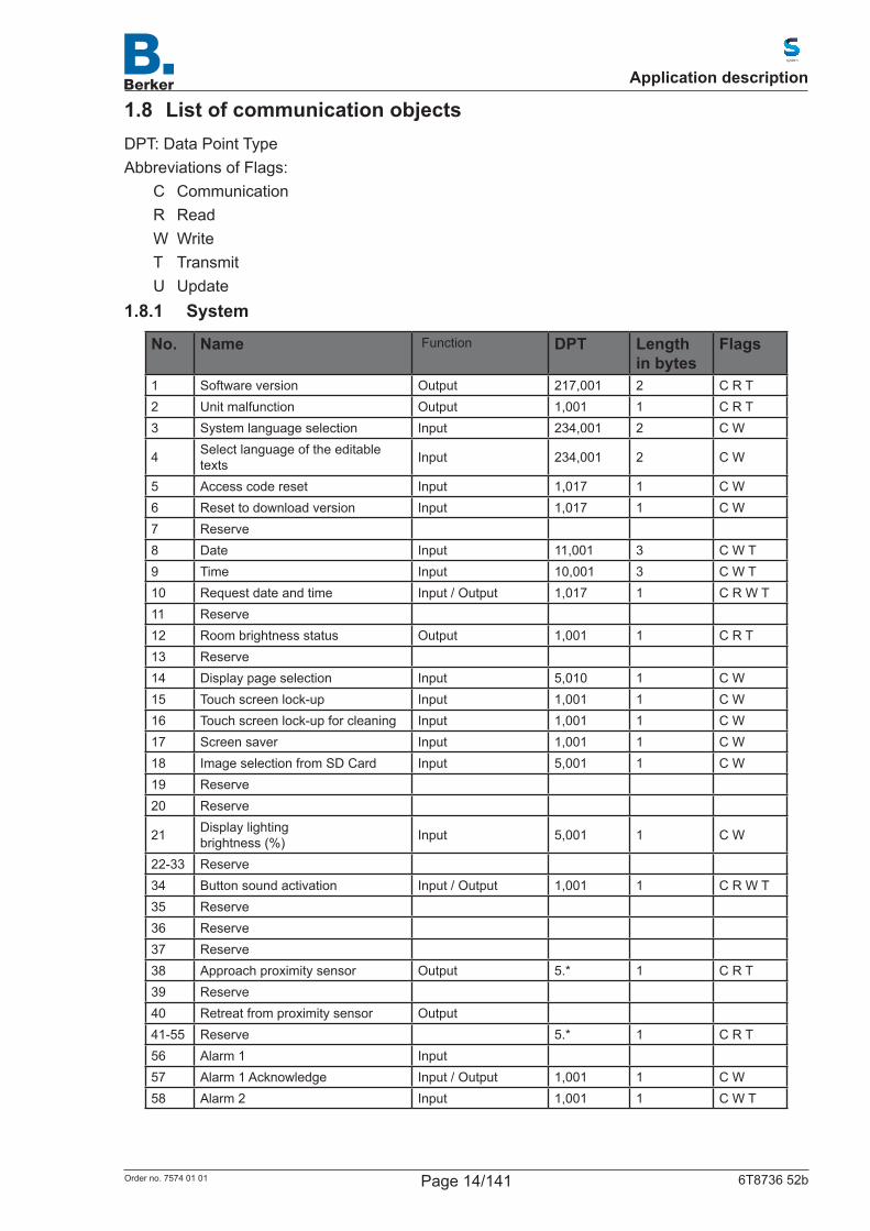
1.8 List of communication objectsDPT: Data Point TypeAbbreviations of Flags:
C CommunicationR ReadW WriteT TransmitU Update
1.8.1 System
No. Name Function DPT Length in bytes
Flags
1 Software version Output 217,001 2 C R T2 Unit malfunction Output 1,001 1 C R T3 System language selection Input 234,001 2 C W
4 Select language of the editable texts Input 234,001 2 C W
5 Access code reset Input 1,017 1 C W6 Reset to download version Input 1,017 1 C W7 Reserve8 Date Input 11,001 3 C W T9 Time Input 10,001 3 C W T10 Requestdateandtime Input / Output 1,017 1 C R W T11 Reserve12 Room brightness status Output 1,001 1 C R T13 Reserve14 Display page selection Input 5,010 1 C W15 Touch screen lock-up Input 1,001 1 C W16 Touch screen lock-up for cleaning Input 1,001 1 C W17 Screen saver Input 1,001 1 C W18 Image selection from SD Card Input 5,001 1 C W19 Reserve20 Reserve
21 Display lighting brightness (%) Input 5,001 1 C W
22-33 Reserve34 Button sound activation Input / Output 1,001 1 C R W T35 Reserve36 Reserve37 Reserve38 Approach proximity sensor Output 5.* 1 C R T 39 Reserve40 Retreat from proximity sensor Output41-55 Reserve 5.* 1 C R T 56 Alarm 1 Input57 Alarm 1 Acknowledge Input / Output 1,001 1 C W58 Alarm 2 Input 1,001 1 C W T
Application description
Page 14/141Order no. 7574 01 01 6T8736 52b
No. Name Function DPT Length in bytes
Flags
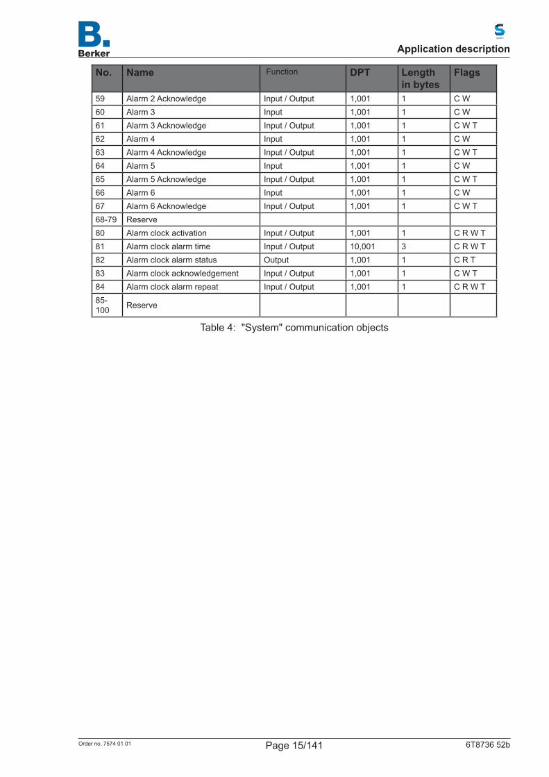
59 Alarm 2 Acknowledge Input / Output 1,001 1 C W60 Alarm 3 Input 1,001 1 C W61 Alarm 3 Acknowledge Input / Output 1,001 1 C W T62 Alarm 4 Input 1,001 1 C W63 Alarm 4 Acknowledge Input / Output 1,001 1 C W T64 Alarm 5 Input 1,001 1 C W65 Alarm 5 Acknowledge Input / Output 1,001 1 C W T66 Alarm 6 Input 1,001 1 C W67 Alarm 6 Acknowledge Input / Output 1,001 1 C W T68-79 Reserve80 Alarm clock activation Input / Output 1,001 1 C R W T81 Alarm clock alarm time Input / Output 10,001 3 C R W T82 Alarm clock alarm status Output 1,001 1 C R T83 Alarm clock acknowledgement Input / Output 1,001 1 C W T84 Alarm clock alarm repeat Input / Output 1,001 1 C R W T85-100 Reserve
Table 4: "System" communication objects
Application description
Page 15/141Order no. 7574 01 01 6T8736 52b
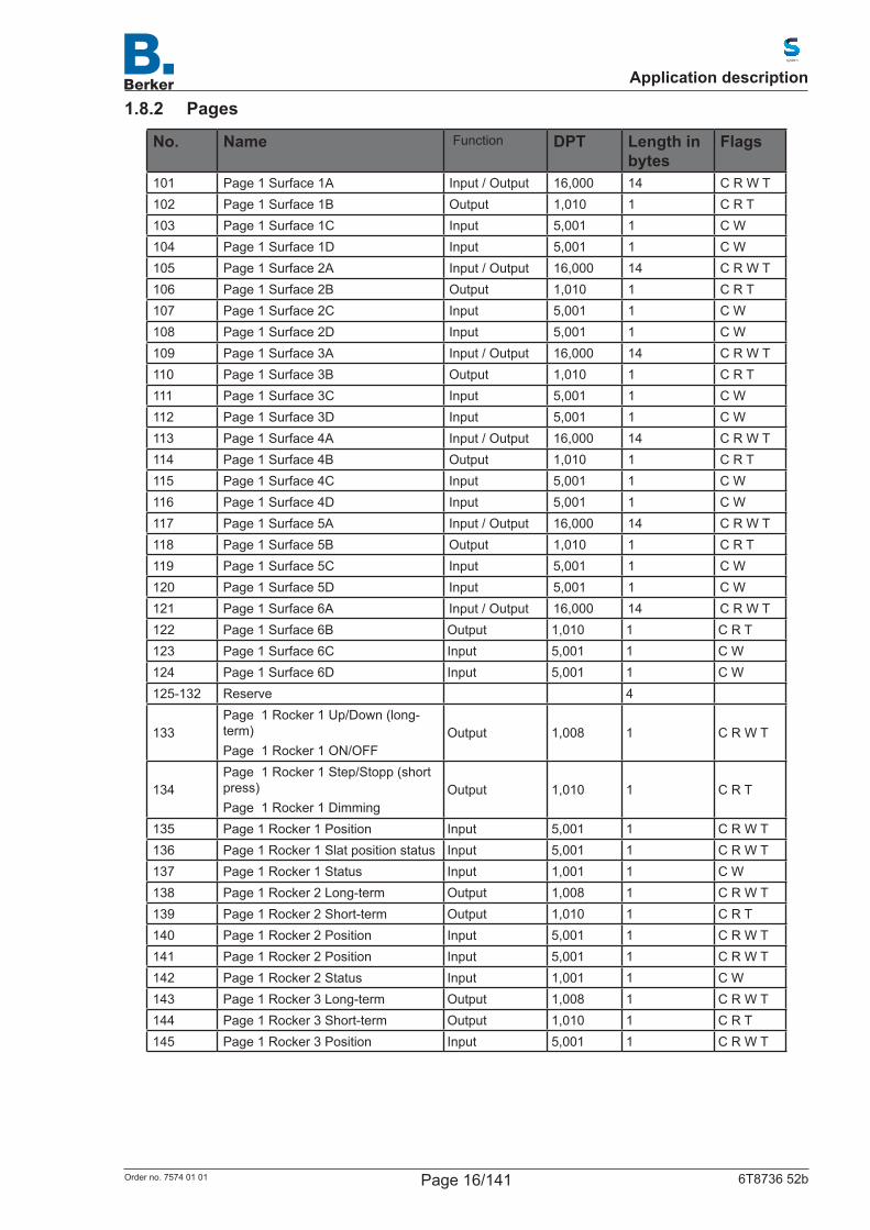
1.8.2 Pages
No. Name Function DPT Length in bytes
Flags
101 Page 1 Surface 1A Input / Output 16,000 14 C R W T102 Page 1 Surface 1B Output 1,010 1 C R T103 Page 1 Surface 1C Input 5,001 1 C W104 Page 1 Surface 1D Input 5,001 1 C W105 Page 1 Surface 2A Input / Output 16,000 14 C R W T106 Page 1 Surface 2B Output 1,010 1 C R T107 Page 1 Surface 2C Input 5,001 1 C W108 Page 1 Surface 2D Input 5,001 1 C W109 Page 1 Surface 3A Input / Output 16,000 14 C R W T110 Page 1 Surface 3B Output 1,010 1 C R T111 Page 1 Surface 3C Input 5,001 1 C W112 Page 1 Surface 3D Input 5,001 1 C W113 Page 1 Surface 4A Input / Output 16,000 14 C R W T114 Page 1 Surface 4B Output 1,010 1 C R T115 Page 1 Surface 4C Input 5,001 1 C W116 Page 1 Surface 4D Input 5,001 1 C W117 Page 1 Surface 5A Input / Output 16,000 14 C R W T118 Page 1 Surface 5B Output 1,010 1 C R T119 Page 1 Surface 5C Input 5,001 1 C W120 Page 1 Surface 5D Input 5,001 1 C W121 Page 1 Surface 6A Input / Output 16,000 14 C R W T122 Page 1 Surface 6B Output 1,010 1 C R T123 Page 1 Surface 6C Input 5,001 1 C W124 Page 1 Surface 6D Input 5,001 1 C W125-132 Reserve 4
133Page 1 Rocker 1 Up/Down (long-term)Page 1 Rocker 1 ON/OFF
Output 1,008 1 C R W T
134Page 1 Rocker 1 Step/Stopp (short press)Page 1 Rocker 1 Dimming
Output 1,010 1 C R T
135 Page 1 Rocker 1 Position Input 5,001 1 C R W T136 Page 1 Rocker 1 Slat position status Input 5,001 1 C R W T137 Page 1 Rocker 1 Status Input 1,001 1 C W138 Page 1 Rocker 2 Long-term Output 1,008 1 C R W T139 Page 1 Rocker 2 Short-term Output 1,010 1 C R T140 Page 1 Rocker 2 Position Input 5,001 1 C R W T141 Page 1 Rocker 2 Position Input 5,001 1 C R W T142 Page 1 Rocker 2 Status Input 1,001 1 C W143 Page 1 Rocker 3 Long-term Output 1,008 1 C R W T144 Page 1 Rocker 3 Short-term Output 1,010 1 C R T145 Page 1 Rocker 3 Position Input 5,001 1 C R W T
Application description
Page 16/141Order no. 7574 01 01 6T8736 52b

No. Name Function DPT Length in bytes Flags
146 Page 1 Rocker 3 Position Input 5,001 1 C R W T147 Page 1 Rocker 3 Status Input 1,001 1 C W148 Page 1 Rotary control Output 14.* 4 C R W T149 Page 1 Rotary control Output 5,001 1 C R W T150 Page 1 Rotary control Output 5,001 1 C R W T151-200 Page 2201-250 Page 3251-300 Page 4301-350 Page 5351-400 Page 6401-450 Page 7501-550 Page 9551-600 Page 10
Table 5: "Pages" communication objects
1.8.3 Automatic
No. Name Function DPT Length in bytes
Flags
601 Automatic inside temperature Input 9,001 2 C W602 Automatic inside humidity value Input 9,007 2 C W
603 Automatic CO2 measuring value in ppm Input 9,008 2 C W
604 Automatic wind speed Input 9,005 2 C W605 Automatic rain Input 1,002 1 C W606 Automatic outside temperature Input 9,001 2 C W607 Automatic brightness value Input 9,004 2 C W608 Automatic cooling status Input 1,001 1 C W609 Automatic sun position azimuth610 Automatic sun position elevation
Table 6: "Automatic 1" communication objects
Application description
Page 17/141Order no. 7574 01 01 6T8736 52b

Objects automatic channels for shading, window, fan or light
N0. Auto 1
No. Auto 1
No. Auto 3
No. Auto 4
No. Auto 5
Name Function DPT Flags
611 653 695 737 779 Auto X Reset / Status Automatic
Input 1,001 C W
612 654 696 738 780 Automatic X Lock-up Input 1,001 C W613 655 697 739 781 Auto X safety Output 1,001 C R T614 656 698 740 782 Auto X rain alarm Output 1,001 C R T615 657 699 741 783 Auto X wind alarm Output 1,001 C R T616 658 700 742 784 Auto X frost alarm Output 1,001 C R T617 659 701 743 785 Auto X status room
temperature lock-upOutput 1,001 C R T
618 660 702 744 786 Auto X status outdoor temperature lock-up
Output 1,001 C R T
619 661 703 745 787 Auto X position Output 5,001 C R T620 662 704 746 788 Auto X slat position Output 5,001 C R T621 663 705 747 789 Auto X status position Input 5,001 C W622 664 706 748 790 Auto X status slat
positionInput 5,001 C W
Table 7: "Automatic for shading, window, fan, light" communication objects
Application description
Page 18/141Order no. 7574 01 01 6T8736 52b

Objects automatic channels for temperature control
N0. Auto 1
No. Auto 1
No. Auto 3
No. Auto 4
No. Auto 5
Name Function DPT Flags
623 665 707 749 791 Auto X temp. HVAC mode, priority 1
Input 1,003 C W
624 666 708 750 792 Auto X temp. HVAC mode, priority 2
Input 1,003 C W
625 667 709 751 793 Auto X temp. HVAC mode frost/heat protection
Input 1,003 C R W T
626 668 710 752 794 Auto X temp. regulator lock-up
Input 1,003 C R W T
627 669 711 753 795 Auto X temp. setpoint current
Output 9,001 C R T
628 670 712 754 796 Auto X temp. changeover object (heating = 1| cooling = 0)
Input 1,002 C W
629 671 713 755 797 Auto X temp. setpoint comfort heating
Input / Output
9,001 C R W T
630 672 714 756 798 Auto X temp. setpoint comfort heating up/down
Input 1,002 C W
631 673 715 757 799 Auto X temp. setpoint comfort cooling
Input / Output
9,001 C R W T
632 674 716 758 800 Auto X temp. setpoint comfort cooling up/down
Input 1,002 C W
633 675 717 759 801 Auto X Temp. base setpoint adjustment
Input 5,001 C W
634 676 718 760 802 Auto X status slat position Input 5,001 C W635 677 719 761 803 Auto x temp. setpoint
standby heatingInput / Output
9,001 C R W T
636 678 720 762 804 Auto X temp. setpoint standby heating up/down
Input 1,002 C W
637 679 721 763 805 Auto X temp. setpoint standby cooling
Input / Output
9,001 C R W T
638 680 722 764 806 Auto X temp. setpoint standby cooling up/down
Input 1,002 C W
638 680 722 764 806 Auto X temp. setpoint night heating
Input / Output
9,001 C R W T
639 681 723 765 807 Auto X temp. setpoint night heating up/down
Output 5,001 C R T
640 682 724 766 808 Auto X temp. setpoint night cooling
Output 5,001 C R T
641 683 725 767 809 Auto X temp. setpoint night cooling up/down
Output 5,001 C R T
642 684 726 768 810 Auto X temp. valve position background heating
Output 5,001 C R T
643 685 727 769 811 Auto X temp. valve position supplementary heating
Output 1,002 C R T
644 686 728 770 812 Auto X temp. valve position background cooling
Output 1,002 C R T
645 687 729 771 813 Auto X temp. valve position supplementary cooling
Output 1,002 C R T
Application description
Page 19/141Order no. 7574 01 01 6T8736 52b
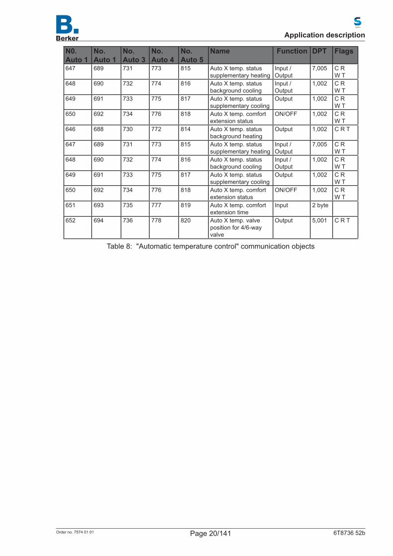
N0. Auto 1
No. Auto 1
No. Auto 3
No. Auto 4
No. Auto 5
Name Function DPT Flags
647 689 731 773 815 Auto X temp. status supplementary heating
Input / Output
7,005 C R W T
648 690 732 774 816 Auto X temp. status background cooling
Input / Output
1,002 C R W T
649 691 733 775 817 Auto X temp. status supplementary cooling
Output 1,002 C R W T
650 692 734 776 818 Auto X temp. comfort extension status
ON/OFF 1,002 C R W T
646 688 730 772 814 Auto X temp. status background heating
Output 1,002 C R T
647 689 731 773 815 Auto X temp. status supplementary heating
Input / Output
7,005 C R W T
648 690 732 774 816 Auto X temp. status background cooling
Input / Output
1,002 C R W T
649 691 733 775 817 Auto X temp. status supplementary cooling
Output 1,002 C R W T
650 692 734 776 818 Auto X temp. comfort extension status
ON/OFF 1,002 C R W T
651 693 735 777 819 Auto X temp. comfort extension time
Input 2 byte
652 694 736 778 820 Auto X temp. valve position for 4/6-way valve
Output 5,001 C R T
Table 8: "Automatic temperature control" communication objects
Application description
Page 20/141Order no. 7574 01 01 6T8736 52b
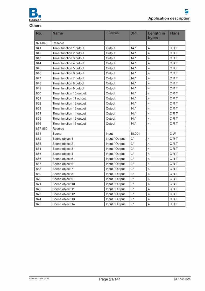
Others
No. Name Function DPT Length in bytes
Flags
821-840 Reserve841 Timer function 1 output Output 14.* 4 C R T842 Timer function 2 output Output 14.* 4 C R T843 Timer function 3 output Output 14.* 4 C R T844 Timer function 4 output Output 14.* 4 C R T845 Timer function 5 output Output 14.* 4 C R T846 Timer function 6 output Output 14.* 4 C R T847 Timer function 7 output Output 14.* 4 C R T848 Timer function 8 output Output 14.* 4 C R T849 Timer function 9 output Output 14.* 4 C R T850 Timer function 10 output Output 14.* 4 C R T851 Timer function 11 output Output 14.* 4 C R T852 Timer function 12 output Output 14.* 4 C R T853 Timer function 13 output Output 14.* 4 C R T854 Timer function 14 output Output 14.* 4 C R T855 Timer function 15 output Output 14.* 4 C R T856 Timer function 16 output Output 14.* 4 C R T857-860 Reserve861 Scene Input 18,001 1 C W862 Scene object 1 Input / Output 9.* 4 C R T863 Scene object 2 Input / Output 9.* 4 C R T864 Scene object 3 Input / Output 9.* 4 C R T865 Scene object 4 Input / Output 9.* 4 C R T866 Scene object 5 Input / Output 9.* 4 C R T867 Scene object 6 Input / Output 9.* 4 C R T868 Scene object 7 Input / Output 9.* 4 C R T869 Scene object 8 Input / Output 9.* 4 C R T870 Scene object 9 Input / Output 9.* 4 C R T871 Scene object 10 Input / Output 9.* 4 C R T872 Scene object 11 Input / Output 9.* 4 C R T873 Scene object 12 Input / Output 9.* 4 C R T874 Scene object 13 Input / Output 9.* 4 C R T875 Scene object 14 Input / Output 9.* 4 C R T
Application description
Page 21/141Order no. 7574 01 01 6T8736 52b
No. Name Function DPT Length in bytes
Flags
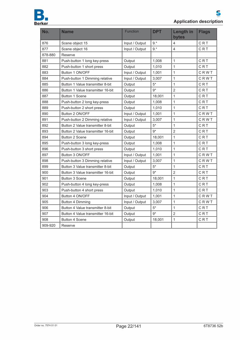
876 Scene object 15 Input / Output 9.* 4 C R T877 Scene object 16 Input / Output 9.* 4 C R T878-880 Reserve881 Push-button 1 long key-press Output 1,008 1 C R T882 Push-button 1 short press Output 1,010 1 C R T883 Button 1 ON/OFF Input / Output 1,001 1 C R W T884 Push-button 1 Dimming relative Input / Output 3,007 1 C R W T885 Button 1 Value transmitter 8-bit Output 5* 1 C R T886 Button 1 Value transmitter 16-bit Output 9* 2 C R T887 Button 1 Scene Output 18,001 1 C R T888 Push-button 2 long key-press Output 1,008 1 C R T889 Push-button 2 short press Output 1,010 1 C R T890 Button 2 ON/OFF Input / Output 1,001 1 C R W T891 Push-button 2 Dimming relative Input / Output 3,007 1 C R W T892 Button 2 Value transmitter 8-bit Output 5* 1 C R T893 Button 2 Value transmitter 16-bit Output 9* 2 C R T894 Button 2 Scene Output 18,001 1 C R T895 Push-button 3 long key-press Output 1,008 1 C R T896 Push-button 3 short press Output 1,010 1 C R T897 Button 3 ON/OFF Input / Output 1,001 1 C R W T898 Push-button 3 Dimming relative Input / Output 3,007 1 C R W T899 Button 3 Value transmitter 8-bit Output 5* 1 C R T900 Button 3 Value transmitter 16-bit Output 9* 2 C R T901 Button 3 Scene Output 18,001 1 C R T902 Push-button 4 long key-press Output 1,008 1 C R T903 Push-button 4 short press Output 1,010 1 C R T904 Button 4 ON/OFF Input / Output 1,001 1 C R W T905 Button 4 Dimming Input / Output 3,007 1 C R W T906 Button 4 Value transmitter 8-bit Output 5* 1 C R T907 Button 4 Value transmitter 16-bit Output 9* 2 C R T908 Button 4 Scene Output 18,001 1 C R T909-920 Reserve
Application description
Page 22/141Order no. 7574 01 01 6T8736 52b
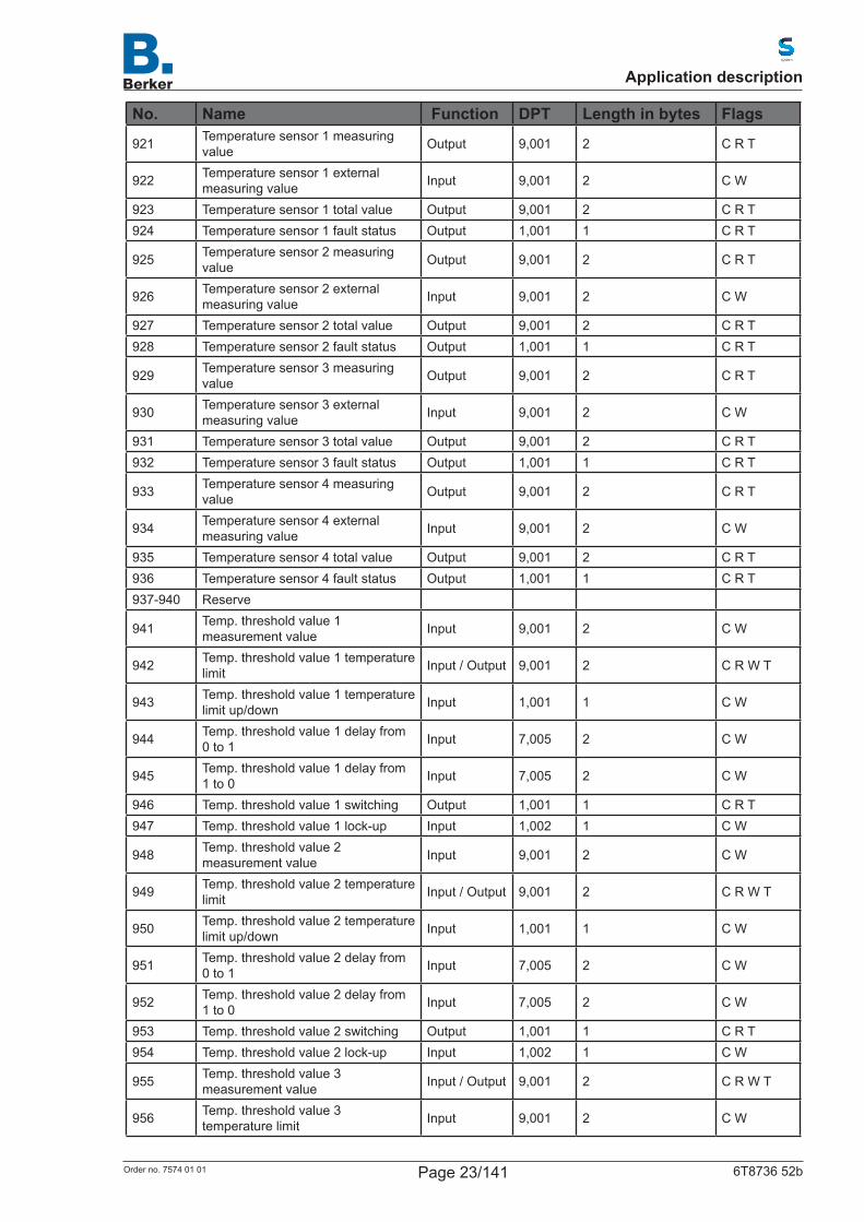
No. Name Function DPT Length in bytes Flags
921 Temperature sensor 1 measuring value Output 9,001 2 C R T
922 Temperature sensor 1 external measuring value Input 9,001 2 C W
923 Temperature sensor 1 total value Output 9,001 2 C R T924 Temperature sensor 1 fault status Output 1,001 1 C R T
925 Temperature sensor 2 measuring value Output 9,001 2 C R T
926 Temperature sensor 2 external measuring value Input 9,001 2 C W
927 Temperature sensor 2 total value Output 9,001 2 C R T928 Temperature sensor 2 fault status Output 1,001 1 C R T
929 Temperature sensor 3 measuring value Output 9,001 2 C R T
930 Temperature sensor 3 external measuring value Input 9,001 2 C W
931 Temperature sensor 3 total value Output 9,001 2 C R T932 Temperature sensor 3 fault status Output 1,001 1 C R T
933 Temperature sensor 4 measuring value Output 9,001 2 C R T
934 Temperature sensor 4 external measuring value Input 9,001 2 C W
935 Temperature sensor 4 total value Output 9,001 2 C R T936 Temperature sensor 4 fault status Output 1,001 1 C R T937-940 Reserve
941 Temp. threshold value 1 measurement value Input 9,001 2 C W
942 Temp. threshold value 1 temperature limit Input / Output 9,001 2 C R W T
943 Temp. threshold value 1 temperature limit up/down Input 1,001 1 C W
944 Temp. threshold value 1 delay from 0 to 1 Input 7,005 2 C W
945 Temp. threshold value 1 delay from 1 to 0 Input 7,005 2 C W
946 Temp. threshold value 1 switching Output 1,001 1 C R T 947 Temp. threshold value 1 lock-up Input 1,002 1 C W
948 Temp. threshold value 2 measurement value Input 9,001 2 C W
949 Temp. threshold value 2 temperature limit Input / Output 9,001 2 C R W T
950 Temp. threshold value 2 temperature limit up/down Input 1,001 1 C W
951 Temp. threshold value 2 delay from 0 to 1 Input 7,005 2 C W
952 Temp. threshold value 2 delay from 1 to 0 Input 7,005 2 C W
953 Temp. threshold value 2 switching Output 1,001 1 C R T954 Temp. threshold value 2 lock-up Input 1,002 1 C W
955 Temp. threshold value 3 measurement value Input / Output 9,001 2 C R W T
956 Temp. threshold value 3 temperature limit Input 9,001 2 C W
Application description
Page 23/141Order no. 7574 01 01 6T8736 52b
No. Name Function DPT Length in bytes
Flags
957 Temp. threshold value 3 temperature limit up/down Input 1,001 1 C W
958 Temp. threshold value 3 delay from 0 to 1 Input 7,005 2 C W
959 Temp. threshold value 3 delay from 1 to 0 Input 7,005 2 C W
960 Temp. threshold value 3 switching Output 1,001 1 C R T961 Temp. threshold value 3 lock-up Input 1,002 1 C W
962 Temp. threshold value 4 measurement value Input 9,001 2 C W
963 Temp. threshold value 4 temperature limit Input / Output 9,001 2 C R W T
964 Temp. threshold value 4 temperature limit up/down Input 1,001 1 C W
965 Temp. threshold value 4 delay from 0 to 1 Input 7,005 2 C W
966 Temp. threshold value 4 delay from 1 to 0 Input 7,005 2 C W
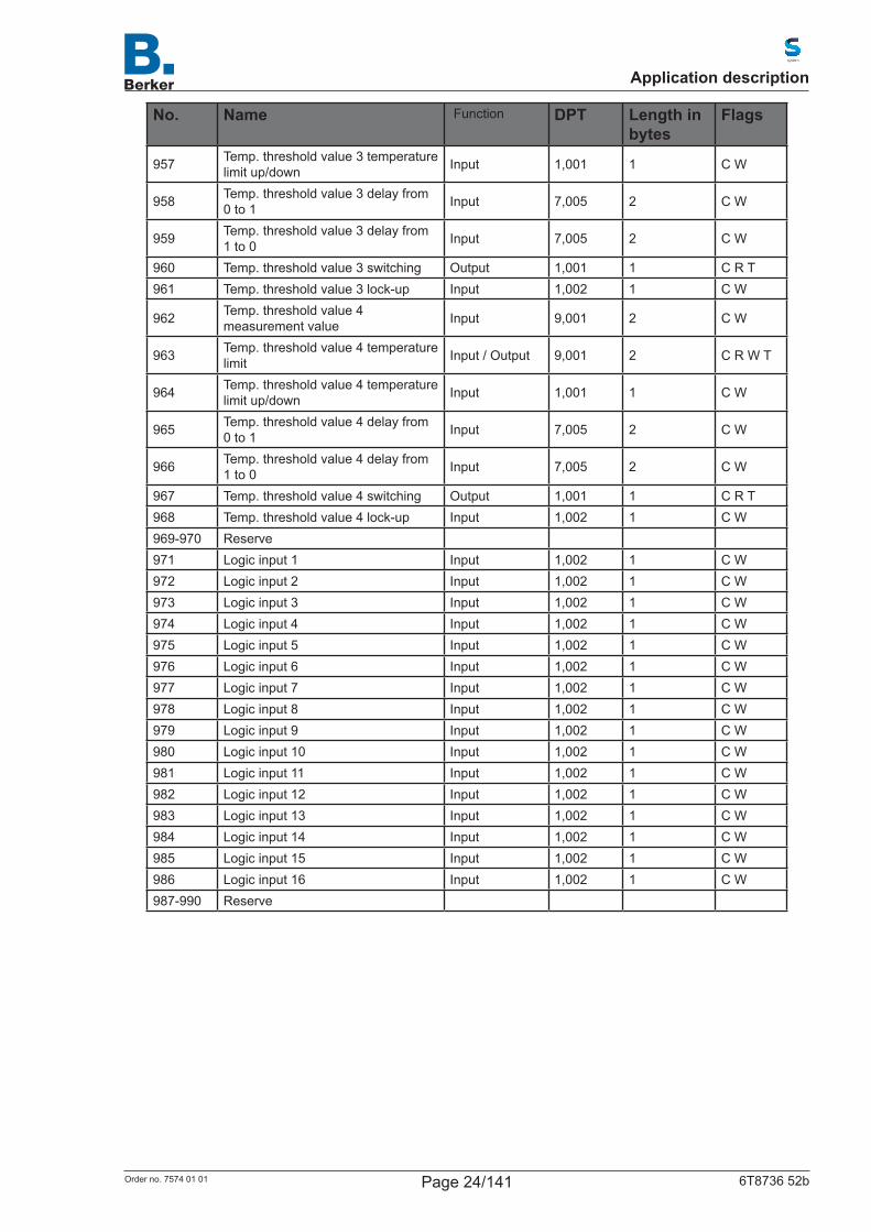
967 Temp. threshold value 4 switching Output 1,001 1 C R T 968 Temp. threshold value 4 lock-up Input 1,002 1 C W969-970 Reserve971 Logic input 1 Input 1,002 1 C W972 Logic input 2 Input 1,002 1 C W973 Logic input 3 Input 1,002 1 C W974 Logic input 4 Input 1,002 1 C W975 Logic input 5 Input 1,002 1 C W976 Logic input 6 Input 1,002 1 C W977 Logic input 7 Input 1,002 1 C W978 Logic input 8 Input 1,002 1 C W979 Logic input 9 Input 1,002 1 C W980 Logic input 10 Input 1,002 1 C W981 Logic input 11 Input 1,002 1 C W982 Logic input 12 Input 1,002 1 C W983 Logic input 13 Input 1,002 1 C W984 Logic input 14 Input 1,002 1 C W985 Logic input 15 Input 1,002 1 C W986 Logic input 16 Input 1,002 1 C W987-990 Reserve
Application description
Page 24/141Order no. 7574 01 01 6T8736 52b
No. Name Function DPT Length in bytes
Flags
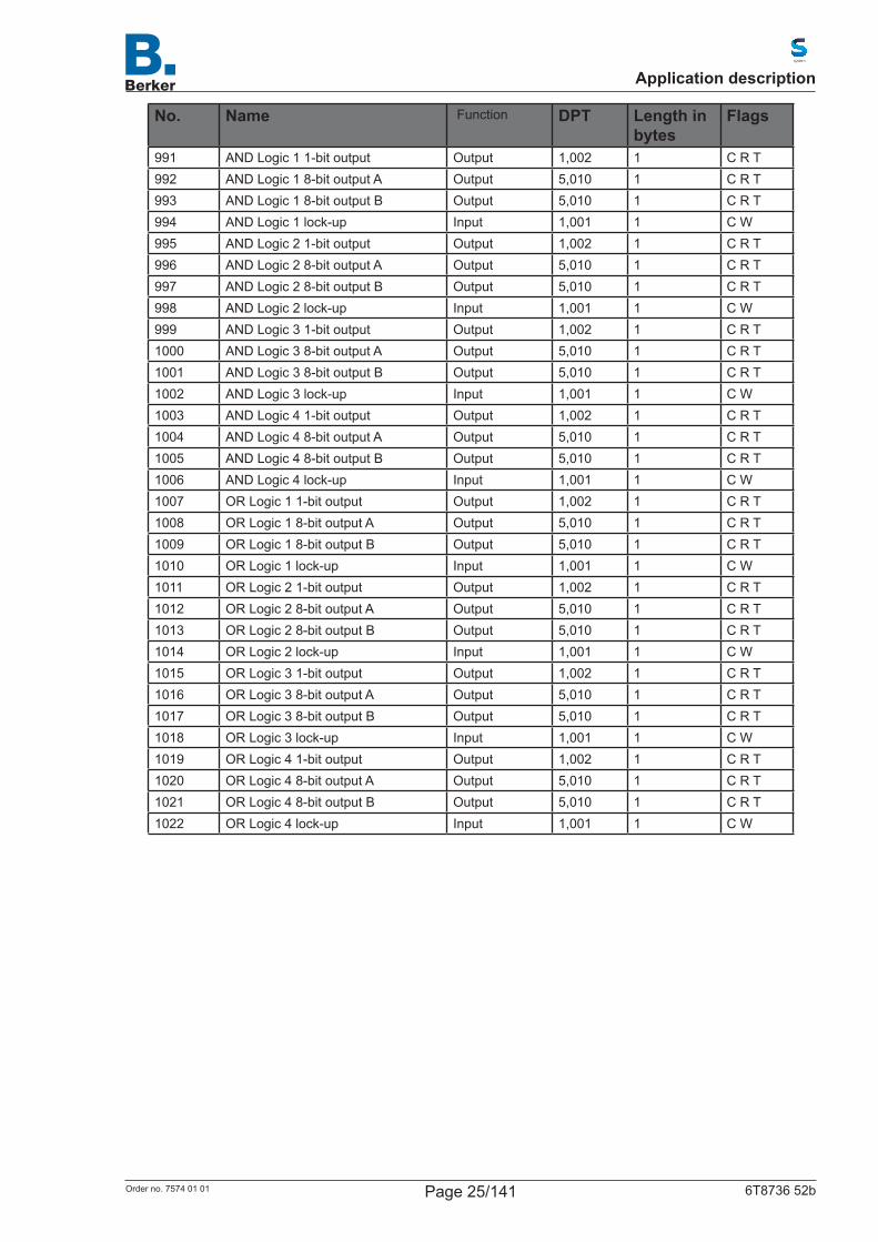
991 AND Logic 1 1-bit output Output 1,002 1 C R T 992 AND Logic 1 8-bit output A Output 5,010 1 C R T 993 AND Logic 1 8-bit output B Output 5,010 1 C R T 994 AND Logic 1 lock-up Input 1,001 1 C W995 AND Logic 2 1-bit output Output 1,002 1 C R T 996 AND Logic 2 8-bit output A Output 5,010 1 C R T 997 AND Logic 2 8-bit output B Output 5,010 1 C R T 998 AND Logic 2 lock-up Input 1,001 1 C W999 AND Logic 3 1-bit output Output 1,002 1 C R T 1000 AND Logic 3 8-bit output A Output 5,010 1 C R T 1001 AND Logic 3 8-bit output B Output 5,010 1 C R T 1002 AND Logic 3 lock-up Input 1,001 1 C W1003 AND Logic 4 1-bit output Output 1,002 1 C R T 1004 AND Logic 4 8-bit output A Output 5,010 1 C R T 1005 AND Logic 4 8-bit output B Output 5,010 1 C R T 1006 AND Logic 4 lock-up Input 1,001 1 C W1007 OR Logic 1 1-bit output Output 1,002 1 C R T 1008 OR Logic 1 8-bit output A Output 5,010 1 C R T 1009 OR Logic 1 8-bit output B Output 5,010 1 C R T 1010 OR Logic 1 lock-up Input 1,001 1 C W1011 OR Logic 2 1-bit output Output 1,002 1 C R T 1012 OR Logic 2 8-bit output A Output 5,010 1 C R T 1013 OR Logic 2 8-bit output B Output 5,010 1 C R T 1014 OR Logic 2 lock-up Input 1,001 1 C W1015 OR Logic 3 1-bit output Output 1,002 1 C R T 1016 OR Logic 3 8-bit output A Output 5,010 1 C R T 1017 OR Logic 3 8-bit output B Output 5,010 1 C R T 1018 OR Logic 3 lock-up Input 1,001 1 C W1019 OR Logic 4 1-bit output Output 1,002 1 C R T 1020 OR Logic 4 8-bit output A Output 5,010 1 C R T 1021 OR Logic 4 8-bit output B Output 5,010 1 C R T 1022 OR Logic 4 lock-up Input 1,001 1 C W
Application description
Page 25/141Order no. 7574 01 01 6T8736 52b
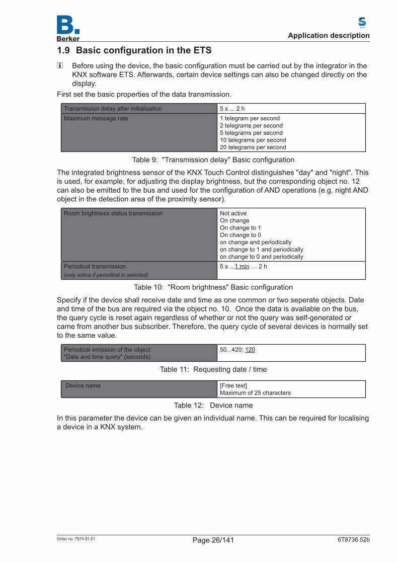
1.9 BasicconfigurationintheETS Beforeusingthedevice,thebasicconfigurationmustbecarriedoutbytheintegratorinthe
KNX software ETS. Afterwards, certain device settings can also be changed directly on the display.
First set the basic properties of the data transmission.
Transmission delay after initialisation 5 s ... 2 hMaximum message rate 1 telegram per second
2 telegrams per second 5 telegrams per second 10 telegrams per second 20 telegrams per second
Table 9: "Transmissiondelay"Basicconfiguration
The integrated brightness sensor of the KNX Touch Control distinguishes "day" and "night". This is used, for example, for adjusting the display brightness, but the corresponding object no. 12 canalsobeemittedtothebusandusedfortheconfigurationofANDoperations(e.g.nightANDobject in the detection area of the proximity sensor).
Room brightness status transmission Not active On change On change to 1 On change to 0 on change and periodically on change to 1 and periodically on change to 0 and periodically
Periodical transmission(only active if periodical is selected)
5 s ...1 min … 2 h
Table 10: "Roombrightness"Basicconfiguration
Specify if the device shall receive date and time as one common or two seperate objects. Date andtimeofthebusarerequiredviatheobjectno.10.Oncethedataisavailableonthebus,thequerycycleisresetagainregardlessofwhetherornotthequerywasself-generatedorcamefromanotherbussubscriber.Therefore,thequerycycleofseveraldevicesisnormallysetto the same value.
Periodical emission of the object "Dateandtimequery"(seconds)
50...420; 120
Table 11: Requestingdate/time
Device name [Free text] Maximum of 25 characters
Table 12: Device name
Inthisparameterthedevicecanbegivenanindividualname.Thiscanberequiredforlocalisinga device in a KNX system.
Application description
Page 26/141Order no. 7574 01 01 6T8736 52b
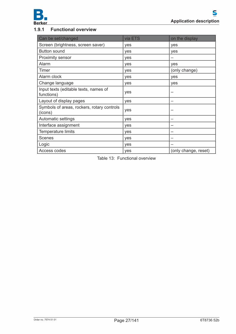
1.9.1 Functional overview
Can be set/changed via ETS on the displayScreen (brightness, screen saver) yes yesButton sound yes yesProximity sensor yes –Alarm yes yesTimer yes (only change)Alarm clock yes yesChange language yes yesInput texts (editable texts, names of functions) yes –
Layout of display pages yes –Symbols of areas, rockers, rotary controls (icons) yes –
Automatic settings yes –Interface assignment yes –Temperature limits yes –Scenes yes –Logic yes –Access codes yes (only change, reset)
Table 13: Functional overview
Application description
Page 27/141Order no. 7574 01 01 6T8736 52b
2. System language selectionThe language used for the display can be changed via an object, on the display or in the ETS menu.
ETS: System language selection
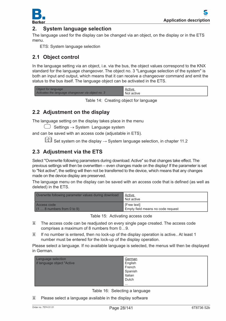
2.1 Object controlIn the language setting via an object, i.e. via the bus, the object values correspond to the KNX standard for the language changeover. The object no. 3 "Language selection of the system" is both an input and output, which means that it can receive a changeover command and emit the status to the bus itself. The language object can be activated in the ETS.
Object for language Activates the language changeover via object no. 3
Active Not active
Table 14: Creating object for language
2.2 Adjustment on the displayThe language setting on the display takes place in the menu
Settings → System Language systemand can be saved with an access code (adjustable in ETS).
ETS
Setsystemonthedisplay→Systemlanguageselection,inchapter11.2
2.3 Adjustment via the ETSSelect "Overwrite following parameters during download: Active" so that changes take effect. The previous settings will then be overwritten – even changes made on the display! If the parameter is set to "Not active", the setting will then not be transferred to the device, which means that any changes made on the device display are preserved.Thelanguagemenuonthedisplaycanbesavedwithanaccesscodethatisdefined(aswellasdeleted) in the ETS.
Overwrite following parameter values during download Active Not active
Access code (1 … 8 numbers from 0 to 9)
[Free text] Emptyfieldmeansnocoderequest
Table 15: Activating access code
The access code can be readjusted on every single page created. The access code comprises a maximum of 8 numbers from 0…9.
If no number is entered, then no lock-up of the display operation is active.. At least 1 number must be entered for the lock-up of the display operation.
Please select a language. If no available language is selected, the menus will then be displayed in German.
Language selection if language object "Active
German English French Spanish Italian Dutch ...
Table 16: Selecting a language
Please select a language available in the display software
Application description
Page 28/141Order no. 7574 01 01 6T8736 52b

3. Language of the editable textsIndividually input texts can be saved in various languages. The displayed language can be changed via an object, on the display or in the ETS menu.
ETS: Language of the editable texts
3.1 Object controlIf a language is set via an object, i.e. via the bus, then use the object table from the chapter "System language selection". The object no. 4 "Language selection of the editable texts" is both an input and output, which means that it can receive a changeover command and emit the status to the bus itself.The language object can be activated in the ETS.
Object for language Activates the language changeover via object no. 4
Active Not active
Table 17: Creating object for language
Thelanguageselectiononthedisplaycanbesavedwithanaccesscodethatisdefined(oreven deleted) in the ETS.
3.2 Adjustment on the displayThe language setting on the display takes place in the menu
Settings System Language of editable textsand can be saved with an access code (adjustable in ETS).
ETS
Set system on the display Language of editable texts, in chapter 11.3 Language of editable texts
3.3 Adjustment via the ETSSelect "Overwrite following parameter values during download: Active" so that changes take effect. The previous settings will then be overwritten – even changes made on the display!Thelanguagemenuonthedisplaycanalsobesavedwithanaccesscodethatisdefined(oreven deleted) in the ETS.
Overwrite following parameter values during download Active Not active
Access code(1 … 8 numbers from 0 to 9)
[Free text]Empty field means no code request
Table 18: Activating access code
The access code can be readjusted on every single page created. The access code comprises a maximum of 8 numbers from 0…9.
Value at initialization language selectionIf language object "Active"
Language selection 1-6
Language selection If language object "Not active"
Language selection 1-6
Table 19: Selecting language
Application description
Page 29/141Order no. 7574 01 01 6T8736 52b

Six languages can be saved. In the parameter table "Example language assignment" the chosen languages are assigned to the six places. The object values correspond to the data point types for the language changeover in the KNX bus.
Example language assignmentLanguage 1 Language 2 Language 3 Language 4 Language 5 Language 6
German English French Spanish Italian Dutch
Table 20: Object values of the languages
Application description
Page 30/141Order no. 7574 01 01 6T8736 52b
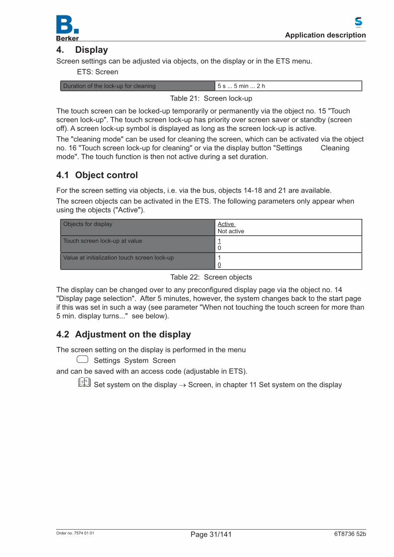
4. DisplayScreen settings can be adjusted via objects, on the display or in the ETS menu.
ETS: Screen
Duration of the lock-up for cleaning 5 s ... 5 min ... 2 h
Table 21: Screen lock-up
The touch screen can be locked-up temporarily or permanently via the object no. 15 "Touch screen lock-up". The touch screen lock-up has priority over screen saver or standby (screen off). A screen lock-up symbol is displayed as long as the screen lock-up is active.The "cleaning mode" can be used for cleaning the screen, which can be activated via the object no. 16 "Touch screen lock-up for cleaning" or via the display button "Settings Cleaning mode". The touch function is then not active during a set duration.
4.1 Object controlFor the screen setting via objects, i.e. via the bus, objects 14-18 and 21 are available.The screen objects can be activated in the ETS. The following parameters only appear when using the objects ("Active").
Objects for display Active Not active
Touch screen lock-up at value 1 0
Value at initialization touch screen lock-up 1 0
Table 22: Screen objects
Thedisplaycanbechangedovertoanypreconfigureddisplaypageviatheobjectno.14"Display page selection". After 5 minutes, however, the system changes back to the start page if this was set in such a way (see parameter "When not touching the touch screen for more than 5 min. display turns..." see below).
4.2 Adjustment on the displayThe screen setting on the display is performed in the menu
Settings System Screenand can be saved with an access code (adjustable in ETS).
ETS
Set system on the display → Screen, in chapter 11 Set system on the display
Application description
Page 31/141Order no. 7574 01 01 6T8736 52b
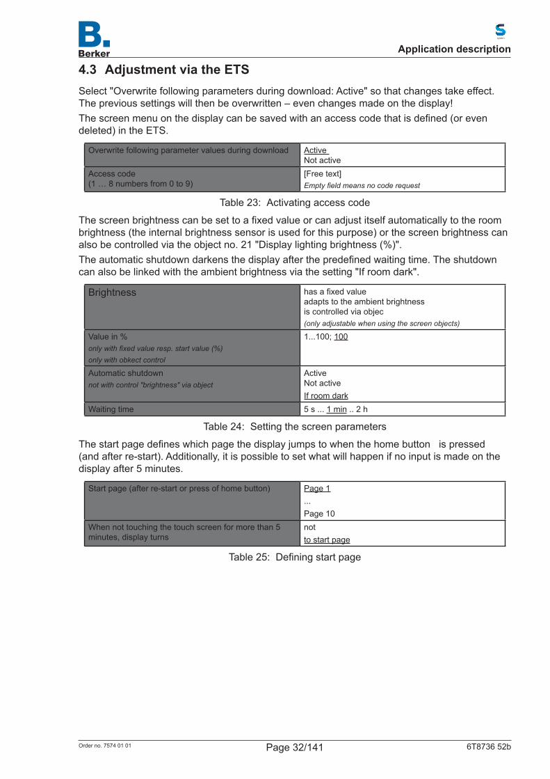
4.3 Adjustment via the ETSSelect "Overwrite following parameters during download: Active" so that changes take effect. The previous settings will then be overwritten – even changes made on the display!Thescreenmenuonthedisplaycanbesavedwithanaccesscodethatisdefined(orevendeleted) in the ETS.
Overwrite following parameter values during download Active Not active
Access code (1 … 8 numbers from 0 to 9)
[Free text]Empty field means no code request
Table 23: Activating access code
Thescreenbrightnesscanbesettoafixedvalueorcanadjustitselfautomaticallytotheroombrightness (the internal brightness sensor is used for this purpose) or the screen brightness can also be controlled via the object no. 21 "Display lighting brightness (%)".Theautomaticshutdowndarkensthedisplayafterthepredefinedwaitingtime.Theshutdowncan also be linked with the ambient brightness via the setting "If room dark".
Brightness hasafixedvalue adapts to the ambient brightness is controlled via objec(only adjustable when using the screen objects)
Value in %only with fixed value resp. start value (%)only with obkect control
1...100; 100
Automatic shutdownnot with control "brightness" via object
Active Not activeIf room dark
Waiting time 5 s ... 1 min .. 2 h
Table 24: Setting the screen parameters
Thestartpagedefineswhichpagethedisplayjumpstowhenthehomebuttonispressed(and after re-start). Additionally, it is possible to set what will happen if no input is made on the display after 5 minutes.
Start page (after re-start or press of home button) Page 1...Page 10
When not touching the touch screen for more than 5 minutes, display turns
notto start page
Table 25: Definingstartpage
Application description
Page 32/141Order no. 7574 01 01 6T8736 52b
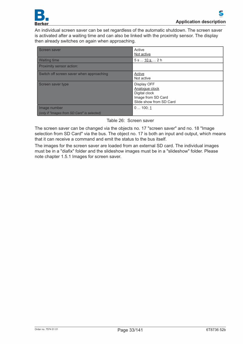
An individual screen saver can be set regardless of the automatic shutdown. The screen saver is activated after a waiting time and can also be linked with the proximity sensor. The display then already switches on again when approaching.
Screen saver Active Not active
Waiting time 5 s ... 10 s … 2 hProximity sensor action:
Switch off screen saver when approaching Active Not active
Screen saver type Display OFF Analogue clock Digital clock Image from SD Card Slide show from SD Card
Image number(only if "Images from SD Card" is selected)
0 ... 100; 1
Table 26: Screen saver
The screen saver can be changed via the objects no. 17 "screen saver" and no. 18 "Image selection from SD Card" via the bus. The object no. 17 is both an input and output, which means that it can receive a command and emit the status to the bus itself.The images for the screen saver are loaded from an external SD card. The individual images mustbeina"diafix"folderandtheslideshowimagesmustbeina"slideshow"folder.Pleasenote chapter 1.5.1 Images for screen saver.
Application description
Page 33/141Order no. 7574 01 01 6T8736 52b
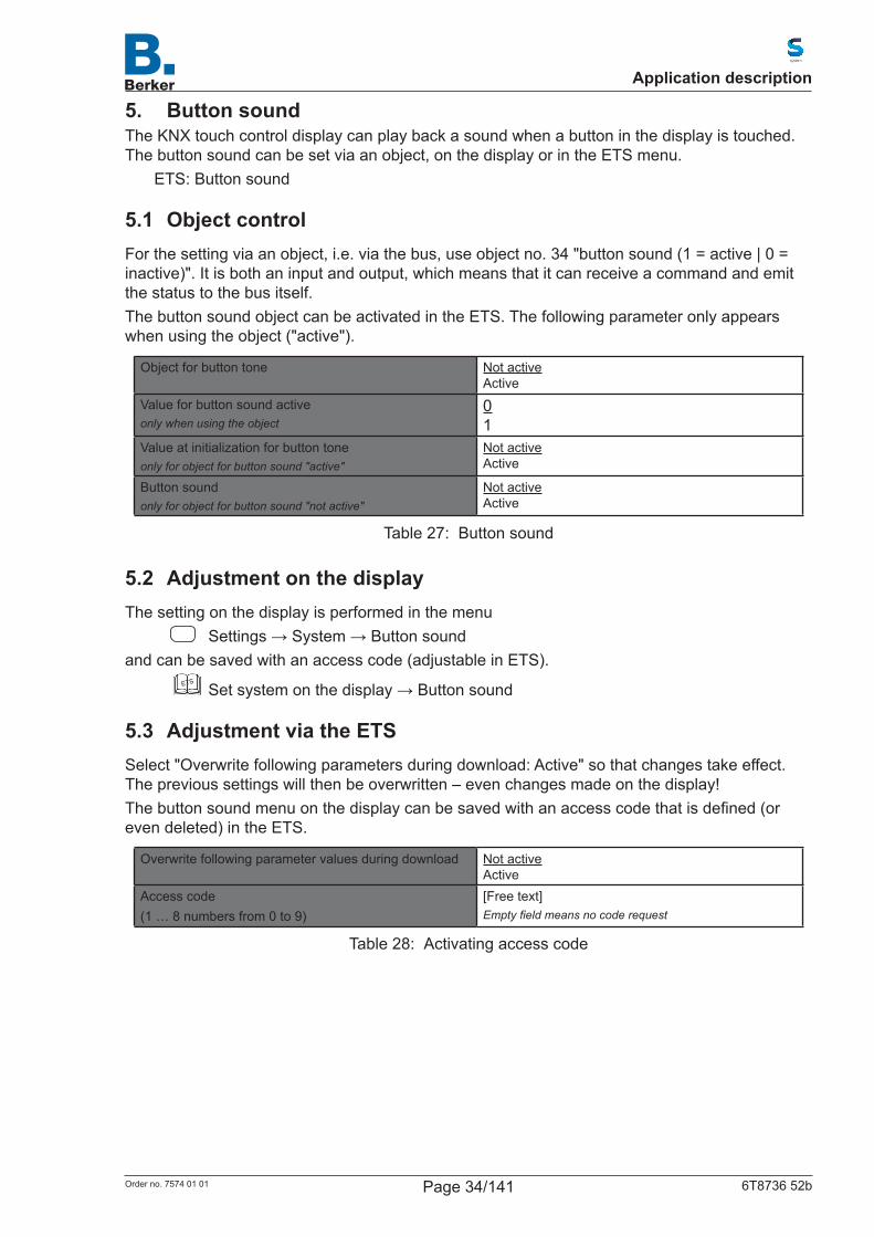
5. Button soundThe KNX touch control display can play back a sound when a button in the display is touched. The button sound can be set via an object, on the display or in the ETS menu.
ETS: Button sound
5.1 Object controlFor the setting via an object, i.e. via the bus, use object no. 34 "button sound (1 = active | 0 = inactive)". It is both an input and output, which means that it can receive a command and emit the status to the bus itself.The button sound object can be activated in the ETS. The following parameter only appears when using the object ("active").
Object for button tone Not active Active
Value for button sound activeonly when using the object
0 1
Value at initialization for button toneonly for object for button sound "active"
Not active Active
Button soundonly for object for button sound "not active"
Not active Active
Table 27: Button sound
5.2 Adjustment on the displayThe setting on the display is performed in the menu
Settings→System→Buttonsoundand can be saved with an access code (adjustable in ETS).
ETS
Setsystemonthedisplay→Buttonsound
5.3 Adjustment via the ETSSelect "Overwrite following parameters during download: Active" so that changes take effect. The previous settings will then be overwritten – even changes made on the display!Thebuttonsoundmenuonthedisplaycanbesavedwithanaccesscodethatisdefined(oreven deleted) in the ETS.
Overwrite following parameter values during download Not active Active
Access code(1 … 8 numbers from 0 to 9)
[Free text]Empty field means no code request
Table 28: Activating access code
Application description
Page 34/141Order no. 7574 01 01 6T8736 52b

6. Proximity sensorThe proximity sensor of the KNX Touch Control registers when a person moves into or retreats from the detection area. In this way, the object no. 38 can be transmitted to the display when approaching, and the object no. 40 can be transmitted to the display when retreating from the detection area.TheobjectfunctionsfortheproximitysensorcanbeconfiguredonlyviatheETS.Eachobjectcanbeconfiguredasabitobjectandcantransmitthevalue1or0ortogglebetween0and1(e.g.forswitchinglights).Ortheobjectcanbeconfiguredasabyteobjectand transmit a value between 0 and 255 or a percentage value (e.g. for dimming lighting, for approaching a shading position or for opening a scene).
Objects for proximity sensorActivates the proximity sensor function
Not active Active
Function when approaching"Approach proximity sensor" object
noneEmission of value 1Emission of value 0Object value is toggledTransmission of value 0 … 255Emission of value 0 … 100%
Function when leaving"Retreat from proximity sensor" object
noneEmission of value 1Emission of value 0Object value is toggledTransmission of value 0 … 255Emission of value 0 … 100%
Transmission delay (seconds)only if something is transmitted
0...240; 2
Valueonly if emission of value 0...255 or 0...100%
0...255; 255or0...100; 100
Table 29: Proximity sensor
Application description
Page 35/141Order no. 7574 01 01 6T8736 52b
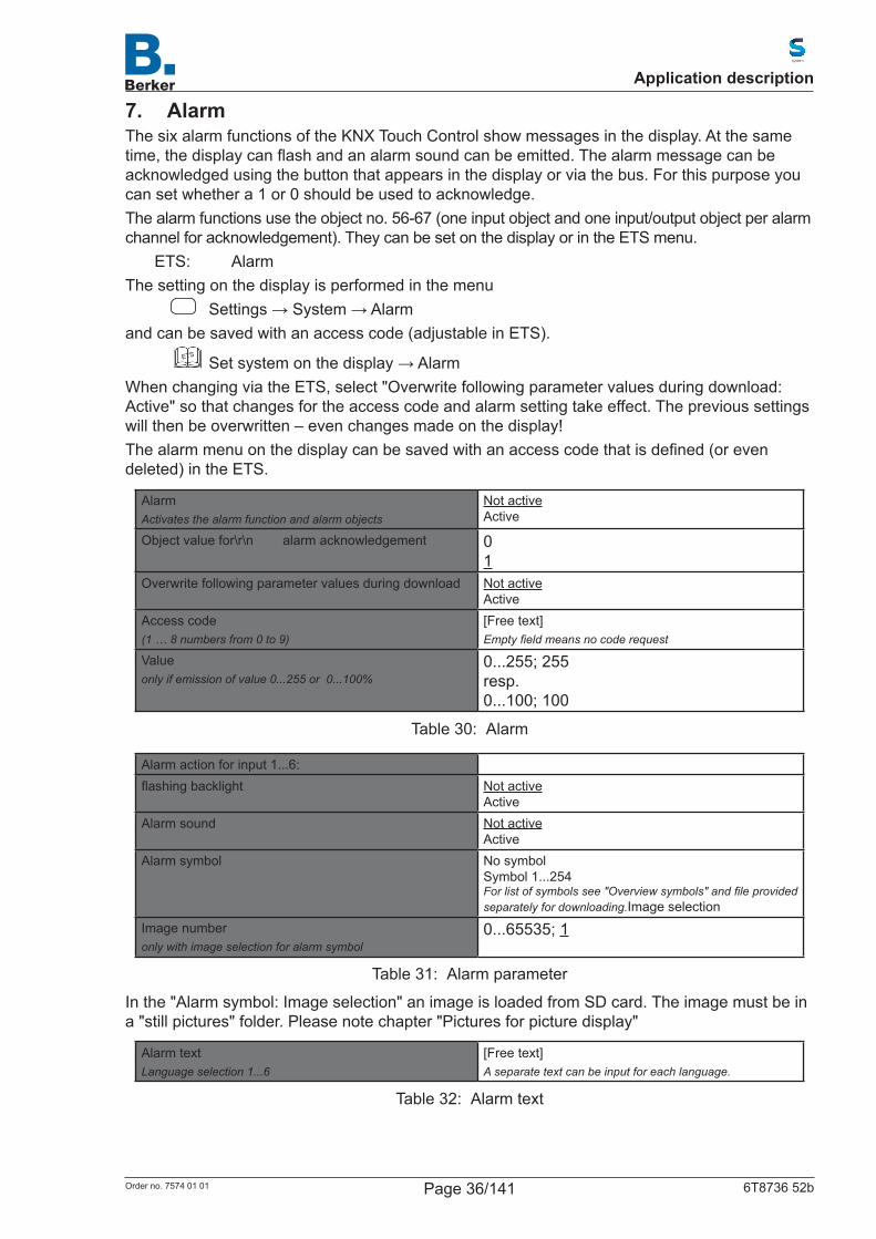
7. AlarmThe six alarm functions of the KNX Touch Control show messages in the display. At the same time,thedisplaycanflashandanalarmsoundcanbeemitted.Thealarmmessagecanbeacknowledged using the button that appears in the display or via the bus. For this purpose you can set whether a 1 or 0 should be used to acknowledge.The alarm functions use the object no. 56-67 (one input object and one input/output object per alarm channel for acknowledgement). They can be set on the display or in the ETS menu.
ETS: AlarmThe setting on the display is performed in the menu
Settings→System→Alarmand can be saved with an access code (adjustable in ETS).
ETS
Setsystemonthedisplay→AlarmWhen changing via the ETS, select "Overwrite following parameter values during download: Active" so that changes for the access code and alarm setting take effect. The previous settings will then be overwritten – even changes made on the display!Thealarmmenuonthedisplaycanbesavedwithanaccesscodethatisdefined(orevendeleted) in the ETS.
AlarmActivates the alarm function and alarm objects
Not active Active
Object value for\r\n alarm acknowledgement 0 1
Overwrite following parameter values during download Not active Active
Access code(1 … 8 numbers from 0 to 9)
[Free text]Empty field means no code request
Valueonly if emission of value 0...255 or 0...100%
0...255; 255 resp. 0...100; 100
Table 30: Alarm
Alarm action for input 1...6:flashingbacklight Not active
ActiveAlarm sound Not active
ActiveAlarm symbol No symbol
Symbol 1...254 For list of symbols see "Overview symbols" and file provided separately for downloading.Image selection
Image numberonly with image selection for alarm symbol
0...65535; 1
Table 31: Alarm parameter
In the "Alarm symbol: Image selection" an image is loaded from SD card. The image must be in a "still pictures" folder. Please note chapter "Pictures for picture display"
Alarm textLanguage selection 1...6
[Free text]A separate text can be input for each language.
Table 32: Alarm text
Application description
Page 36/141Order no. 7574 01 01 6T8736 52b
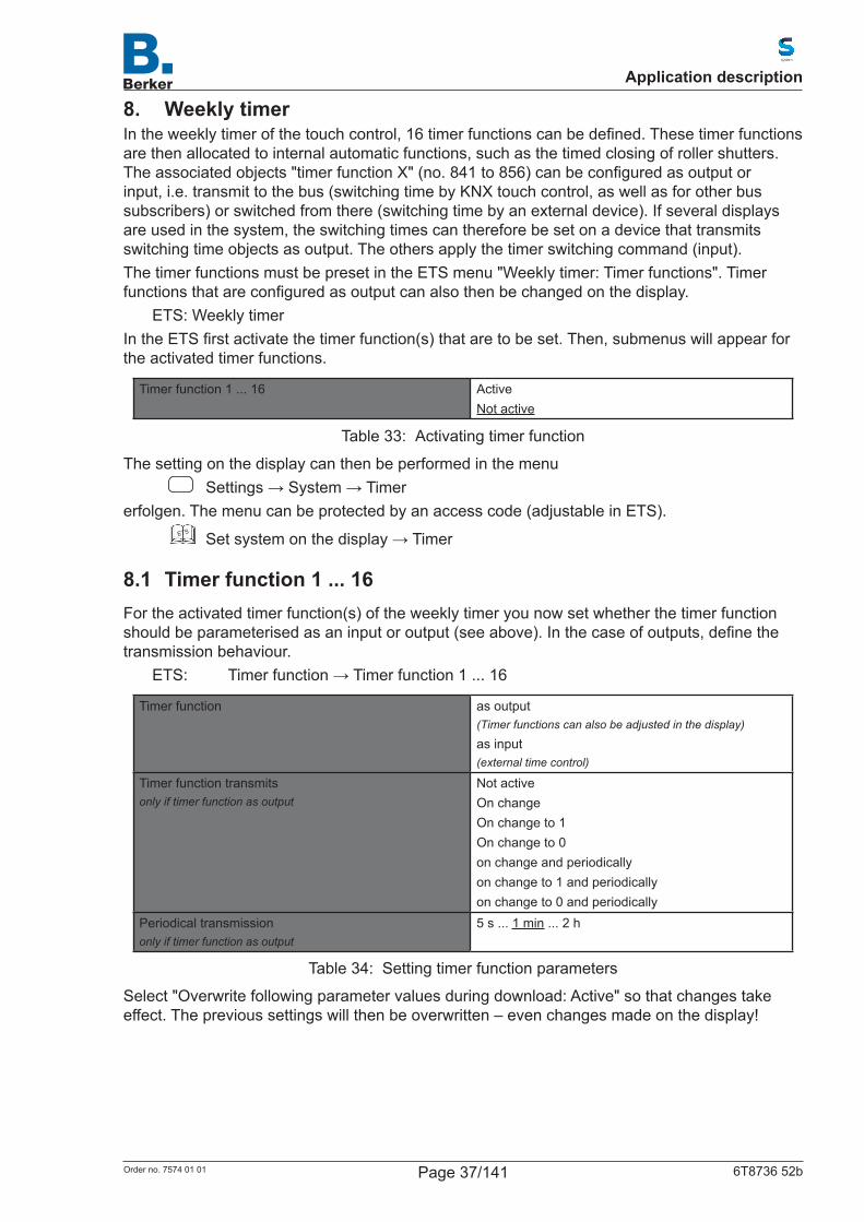
8. Weekly timerIntheweeklytimerofthetouchcontrol,16timerfunctionscanbedefined.Thesetimerfunctionsare then allocated to internal automatic functions, such as the timed closing of roller shutters. Theassociatedobjects"timerfunctionX"(no.841to856)canbeconfiguredasoutputorinput, i.e. transmit to the bus (switching time by KNX touch control, as well as for other bus subscribers) or switched from there (switching time by an external device). If several displays are used in the system, the switching times can therefore be set on a device that transmits switching time objects as output. The others apply the timer switching command (input).The timer functions must be preset in the ETS menu "Weekly timer: Timer functions". Timer functionsthatareconfiguredasoutputcanalsothenbechangedonthedisplay.
ETS: Weekly timerIntheETSfirstactivatethetimerfunction(s)thataretobeset.Then,submenuswillappearforthe activated timer functions.
Timer function 1 ... 16 ActiveNot active
Table 33: Activating timer function
The setting on the display can then be performed in the menu Settings→System→Timer
erfolgen. The menu can be protected by an access code (adjustable in ETS).ETS Setsystemonthedisplay→Timer
8.1 Timer function 1 ... 16For the activated timer function(s) of the weekly timer you now set whether the timer function shouldbeparameterisedasaninputoroutput(seeabove).Inthecaseofoutputs,definethetransmission behaviour.
ETS: Timerfunction→Timerfunction1...16
Timer function as output(Timer functions can also be adjusted in the display)
as input(external time control)
Timer function transmitsonly if timer function as output
Not activeOn changeOn change to 1On change to 0on change and periodicallyon change to 1 and periodicallyon change to 0 and periodically
Periodical transmissiononly if timer function as output
5 s ... 1 min ... 2 h
Table 34: Setting timer function parameters
Select "Overwrite following parameter values during download: Active" so that changes take effect. The previous settings will then be overwritten – even changes made on the display!
Application description
Page 37/141Order no. 7574 01 01 6T8736 52b
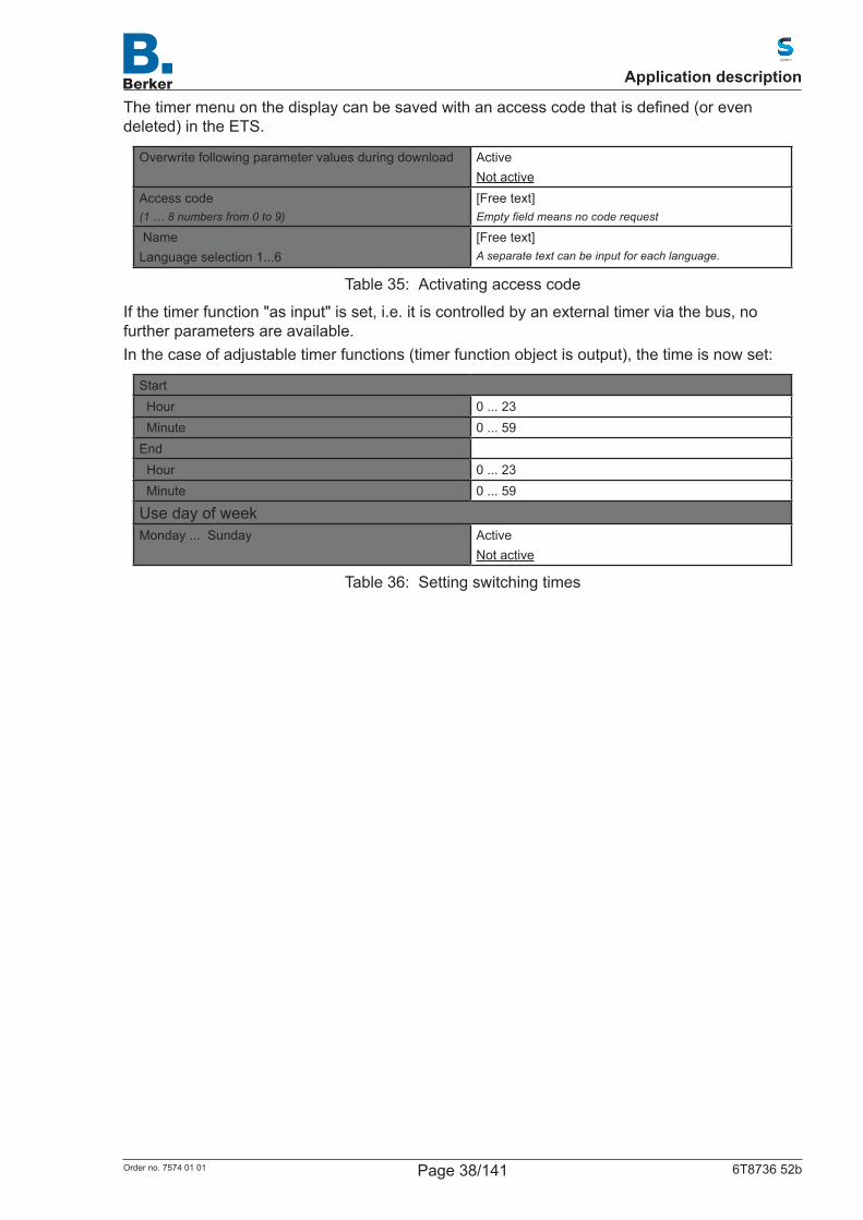
Thetimermenuonthedisplaycanbesavedwithanaccesscodethatisdefined(orevendeleted) in the ETS.
Overwrite following parameter values during download ActiveNot active
Access code(1 … 8 numbers from 0 to 9)
[Free text]Empty field means no code request
NameLanguage selection 1...6
[Free text]A separate text can be input for each language.
Table 35: Activating access code
If the timer function "as input" is set, i.e. it is controlled by an external timer via the bus, no further parameters are available.In the case of adjustable timer functions (timer function object is output), the time is now set:
Start Hour 0 ... 23 Minute 0 ... 59End Hour 0 ... 23 Minute 0 ... 59
Use day of weekMonday ... Sunday Active
Not active
Table 36: Setting switching times
Application description
Page 38/141Order no. 7574 01 01 6T8736 52b

9. Alarm clockTheKNXtouchcontroldisplaycantriggeranalarmwithsoundandflashingdisplayatasettime. Simultaneously, the time and a button for switching off the alarm appears in the display.The alarm function of the KNX Touch Control can be set via an object, on the display or in the ETS menu.
ETS: Alarm clock
9.1 Object controlFor the screen setting via objects, i.e. via the bus, objects 80-84 are available. They are both an input and output, which means that they can receive a status change as well as emit the status to the bus themselves. Thus, for example, the alarm clock can also be activated, switched off or set to snooze mode from another place in the building.The object no. 81 emits or receives the "Alarm clock alarm time". Thus, the alarm clock can also be set from another display.Theobjectno.82"Alarmclockalarmstatus"canbeconfiguredasabitobjectandcantransmitthevalue1or0(e.g.forswitchinglights).Ortheobjectcanbeconfiguredasabyteobjectand transmit a value between 0 and 255 or a percentage value (e.g. for dimming lighting, for approaching a shading position or for opening a scene).The "objects for alarm clock" can be activated in the ETS. The following parameters only appear when using the objects ("Active").
Object for alarm clock ActiveNot active
Object value for alarm activation 01
Object value for\r\n alarm acknowledgement 01
Object value for alarm repeat 01
Alarm clock action noneEmission of value 1Emission of value 0Transmission of value 0 … 255Transmission of value 0 … 100%
Valueonly with alarm clock action value 0…255 or value 0…100%
0 ... 255; 255 resp.0 ... 100; 100
Use day of weekMonday ... Sunday Active
Not active
Table 37: Alarm clock
9.2 Adjustment on the displayThe setting on the display is performed in the menu
Settings→System→Alarmclockand can be saved with an access code (adjustable in ETS).
ETS Setsystemonthedisplay→Alarm
Application description
Page 39/141Order no. 7574 01 01 6T8736 52b

9.3 Adjustment via the ETSSelect "Overwrite following parameters during download: Active" so that changes take effect. The previous settings will then be overwritten – even changes made on the display!Thealarmclockmenuonthedisplaycanbesavedwithanaccesscodethatisdefined(orevendeleted) in the ETS.
Overwrite following parameter values during download ActiveNot active
Access code(1 … 8 numbers from 0 to 9)
[Free text]Empty field means no code request
Table 38: Activating access code
Alarm time hour 0 ... 23Alarm time minute 0 ... 59Alarm duration 5 s ... 30 min ... 2 h
until acknowledgement
Alarm repetition in snooze mode(minutes)
0 ... 30; 5
Alarm sound ActiveNot active
Displaylightingflashesonalarm ActiveNot active
Table 39: Setting the wake-up/ alarm times
Application description
Page 40/141Order no. 7574 01 01 6T8736 52b
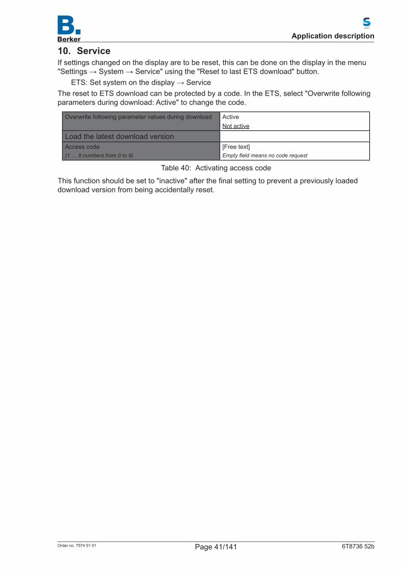
10. ServiceIf settings changed on the display are to be reset, this can be done on the display in the menu "Settings→System→Service"usingthe"ResettolastETSdownload"button.
ETS:Setsystemonthedisplay→ServiceThe reset to ETS download can be protected by a code. In the ETS, select "Overwrite following parameters during download: Active" to change the code.
Overwrite following parameter values during download ActiveNot active
Load the latest download versionAccess code(1 … 8 numbers from 0 to 9)
[Free text]Empty field means no code request
Table 40: Activating access code
Thisfunctionshouldbesetto"inactive"afterthefinalsettingtopreventapreviouslyloadeddownload version from being accidentally reset.
Application description
Page 41/141Order no. 7574 01 01 6T8736 52b

11. Set system on the displayBeforeusingthedevice,thebasicconfigurationmustbecarriedoutbytheintegratorintheKNXsoftwareETS.Afterwards,specificdevicesettingscanalsobechangeddirectlyonthedisplay: – System language selection – Language of the editable texts – Display – Button sound – Alarm – Timer – Alarm clock – Service
You can access the system settings via the symbol on the display pages.Duringtheconfigurationofthedisplaypages,thesymbolcanbesetas"visible"or"invisible".Ifsystem settings are to be possible on the display, the symbol must be displayed on one page at least.
ETS: Configurationofpages
Page 5 Page 6 Page 7
Thu. 30.06.14 10:34
LIGHT BATHROOM
Off
Cleaning mode
Settings
System
Figure 3: System settings on the display
With the return arrow you return to the previous menu page without saving.With the home button you return to the standard page without saving.
Application description
Page 42/141Order no. 7574 01 01 6T8736 52b
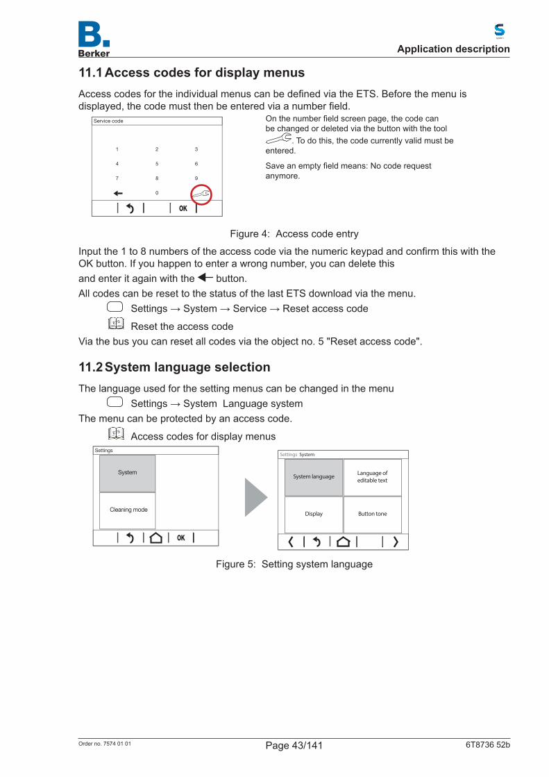
11.1 Access codes for display menusAccesscodesfortheindividualmenuscanbedefinedviatheETS.Beforethemenuisdisplayed,thecodemustthenbeenteredviaanumberfield.
1 2 3
4 5 6
7 8 9
0
Service code
Onthenumberfieldscreenpage,thecodecanbe changed or deleted via the button with the tool
. To do this, the code currently valid must be entered.
Saveanemptyfieldmeans:Nocoderequestanymore.
Figure 4: Access code entry
Inputthe1to8numbersoftheaccesscodeviathenumerickeypadandconfirmthiswiththeOK button. If you happen to enter a wrong number, you can delete thisand enter it again with the button.All codes can be reset to the status of the last ETS download via the menu.
Settings→System→Service→ResetaccesscodeETS Reset the access code
Via the bus you can reset all codes via the object no. 5 "Reset access code".
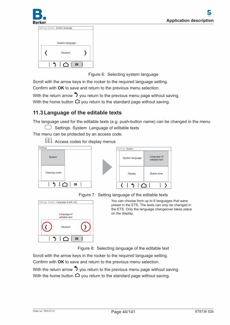
11.2 System language selectionThe language used for the setting menus can be changed in the menu
Settings→SystemLanguagesystemThe menu can be protected by an access code.
ETS Access codes for display menus
Cleaning mode
Settings
System
Display
Settings System
Button tone
Language of editable text
System language
Figure 5: Setting system language
Application description
Page 43/141Order no. 7574 01 01 6T8736 52b
Deutsch
System language
Settings System System language
Figure 6: Selecting system language
Scrollwiththearrowkeysintherockertotherequiredlanguagesetting.ConfirmwithOK to save and return to the previous menu selection.
With the return arrow you return to the previous menu page without saving.With the home button you return to the standard page without saving.
11.3 Language of the editable textsThe language used for the editable texts (e.g. push-button name) can be changed in the menu
Settings System Language of editable textsThe menu can be protected by an access code.
ETS Access codes for display menus
Cleaning mode
Settings
System
Button toneDisplay
Language ofeditable text
System language
Settings System
Figure 7: Setting language of the editable texts
Deutsch
Language ofeditable text
Settings System Language of edit. text
You can choose from up to 6 languages that were preset in the ETS. The texts can only be changed in the ETS. Only the language changeover takes place on the display.
Figure 8: Selecting language of the editable text
Scrollwiththearrowkeysintherockertotherequiredlanguagesetting.ConfirmwithOK to save and return to the previous menu selection.
With the return arrow you return to the previous menu page without saving.With the home button you return to the standard page without saving.
Application description
Page 44/141Order no. 7574 01 01 6T8736 52b
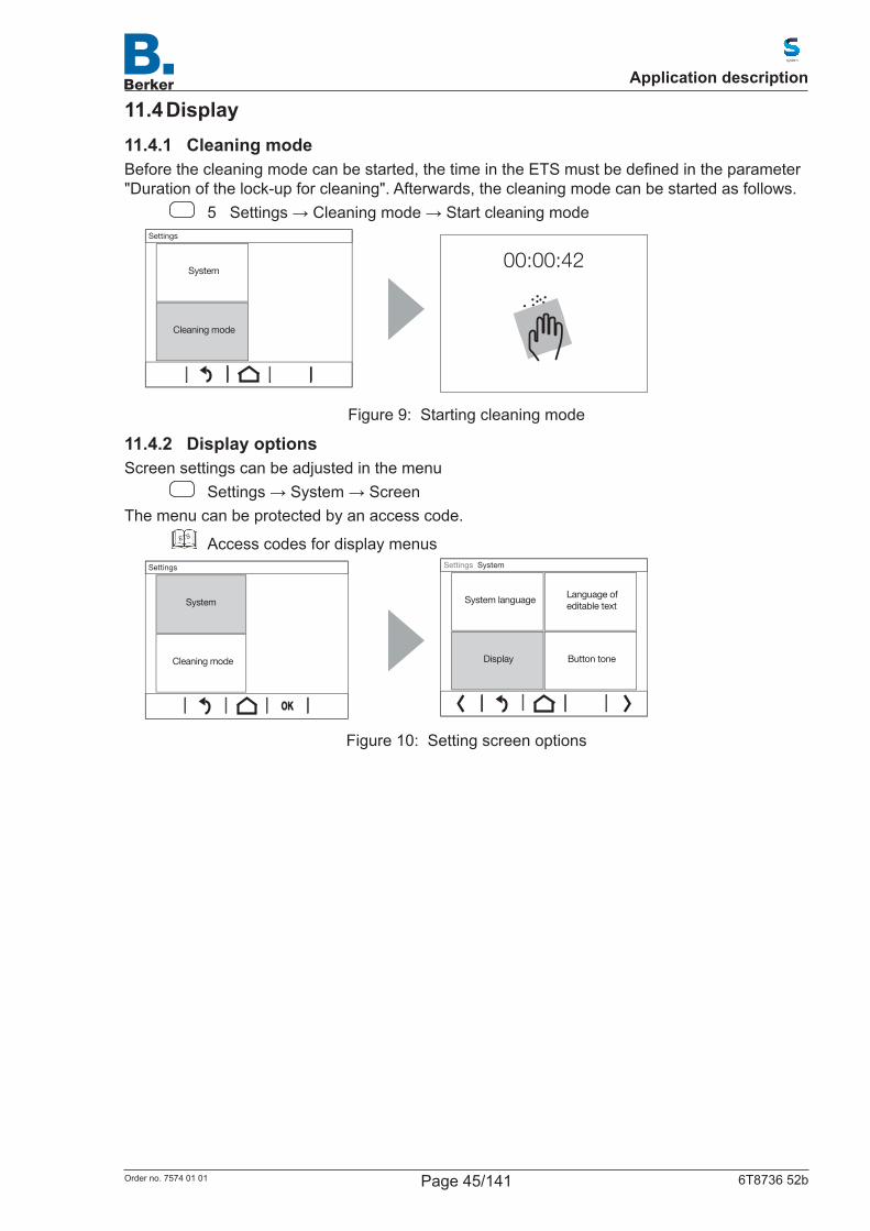
11.4 Display11.4.1 Cleaning modeBeforethecleaningmodecanbestarted,thetimeintheETSmustbedefinedintheparameter"Duration of the lock-up for cleaning". Afterwards, the cleaning mode can be started as follows.
5 Settings→Cleaningmode→Startcleaningmode
Cleaning mode
System
Settings
00:00:42
Figure 9: Starting cleaning mode
11.4.2 Display optionsScreen settings can be adjusted in the menu
Settings→System→ScreenThe menu can be protected by an access code.
ETS Access codes for display menus
Cleaning mode
Settings
System
Button toneDisplay
Language of editable text
System language
Settings System
Figure 10: Setting screen options
Application description
Page 45/141Order no. 7574 01 01 6T8736 52b
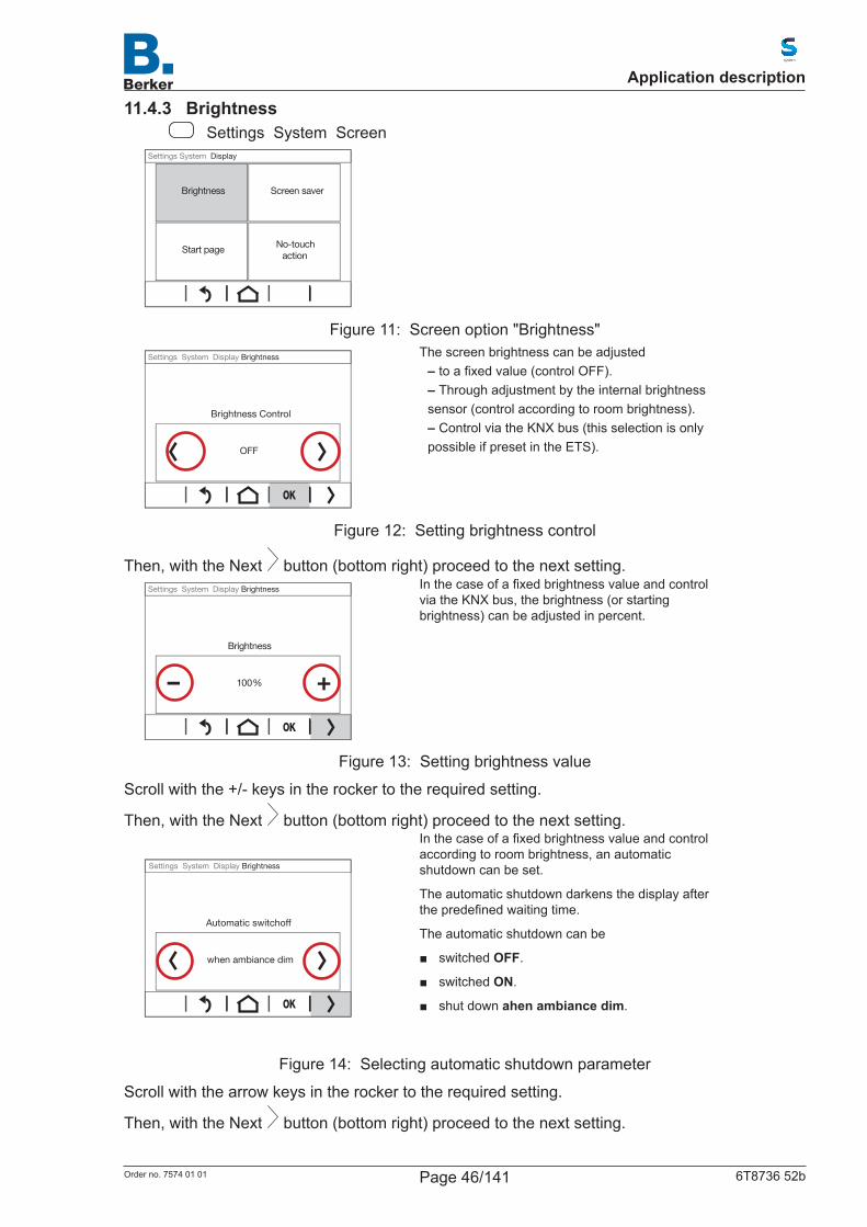
11.4.3 Brightness Settings System Screen
No-touchaction
Start page
Screen saverBrightness
Settings System Display
Figure 11: Screen option "Brightness"
OFF
Brightness Control
Settings System Display Brightness
The screen brightness can be adjusted – toafixedvalue(controlOFF). – Through adjustment by the internal brightness
sensor (control according to room brightness). – Control via the KNX bus (this selection is only
possible if preset in the ETS).
Figure 12: Setting brightness control
Then, with the Next button (bottom right) proceed to the next setting.
– +100%
Brightness
Settings System Display Brightness
Inthecaseofafixedbrightnessvalueandcontrolvia the KNX bus, the brightness (or starting brightness) can be adjusted in percent.
Figure 13: Setting brightness value
Scrollwiththe+/-keysintherockertotherequiredsetting.
Then, with the Next button (bottom right) proceed to the next setting.
when ambiance dim
Automatic switchoff
Settings System Display Brightness
Inthecaseofafixedbrightnessvalueandcontrolaccording to room brightness, an automatic shutdown can be set.
The automatic shutdown darkens the display after thepredefinedwaitingtime.
The automatic shutdown can be
■ switchedOFF.
■ switchedON.
■ shutdownahen ambiance dim.
Figure 14: Selecting automatic shutdown parameter
Scrollwiththearrowkeysintherockertotherequiredsetting.
Then, with the Next button (bottom right) proceed to the next setting.
Application description
Page 46/141Order no. 7574 01 01 6T8736 52b
– +1 min.
Switches off, if the screen has not been touched for
Settings System Display Brightness
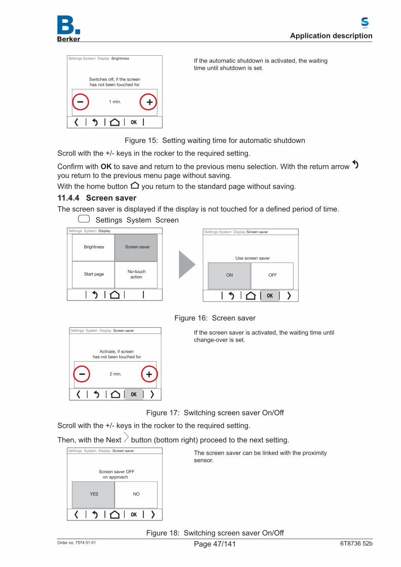
If the automatic shutdown is activated, the waiting time until shutdown is set.
Figure 15: Setting waiting time for automatic shutdown
Scrollwiththe+/-keysintherockertotherequiredsetting.
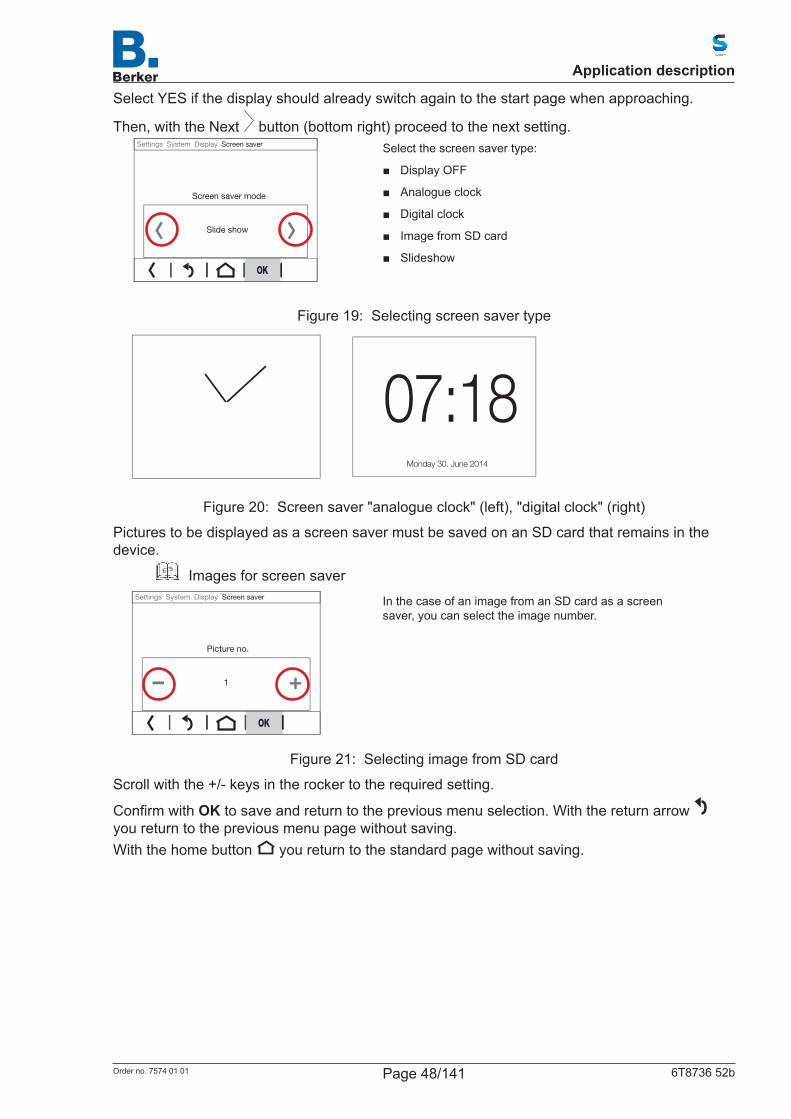
ConfirmwithOK to save and return to the previous menu selection. With the return arrow you return to the previous menu page without saving.With the home button you return to the standard page without saving.11.4.4 Screen saverThescreensaverisdisplayedifthedisplayisnottouchedforadefinedperiodoftime.
Settings System Screen
No-touchaction
Start page
Screen saverBrightness
Settings System Display
OFFON
Use screen saver
Settings System Display Screen saver
Figure 16: Screen saver
2 min.
Activate, if screenhas not been touched for
Settings System Display Screen saver
If the screen saver is activated, the waiting time until change-over is set.
Figure 17: Switching screen saver On/Off
Scrollwiththe+/-keysintherockertotherequiredsetting.
Then, with the Next button (bottom right) proceed to the next setting.
YES NO
Screen saver OFFon approach
Settings System Display Screen saver
The screen saver can be linked with the proximity sensor.
Figure 18: Switching screen saver On/Off
Application description
Page 47/141Order no. 7574 01 01 6T8736 52b
Select YES if the display should already switch again to the start page when approaching.
Then, with the Next button (bottom right) proceed to the next setting.
Slide show
Screen saver mode
Settings System Display Screen saver
Select the screen saver type:
■ DisplayOFF
■ Analogueclock
■ Digitalclock
■ ImagefromSDcard
■ Slideshow
Figure 19: Selecting screen saver type
07:18Monday 30. June 2014
Figure 20: Screen saver "analogue clock" (left), "digital clock" (right)
Pictures to be displayed as a screen saver must be saved on an SD card that remains in the device.
ETS Images for screen saver
– +1
Picture no.
Settings System Display Screen saver
In the case of an image from an SD card as a screen saver, you can select the image number.
Figure 21: Selecting image from SD card
Scrollwiththe+/-keysintherockertotherequiredsetting.
ConfirmwithOK to save and return to the previous menu selection. With the return arrow you return to the previous menu page without saving.With the home button you return to the standard page without saving.
Application description
Page 48/141Order no. 7574 01 01 6T8736 52b

11.4.5 Start pageThestartpagedefineswhichpagethedisplayjumpstowhenthehomebuttonispressed(andafter re-start).
Settings System Screen
No-touchaction
Start page
Screen saverBrightness
Settings System Display
Figure 22: Setting start page
Page1
Start page after reset andafter pressing home button
Settings System Display Start page
AlldisplaypagesdefinedintheETScanbedefinedas a start page.
Figure 23: Selecting start page
Scrollwiththe+/-arrowkeysintherockertotherequiredstartpage.
ConfirmwithOK to save and return to the previous menu selection. With the return arrow you return to the previous menu page without saving.With the home button you return to the standard page without saving.11.4.6 Do not touch actionTheactiondefineswhathappensifnoinputismadeonthedisplayafter5minutes.
Settings System Screen
No-touchaction
Start page
Screen saverBrightness
Settings System Display
Figure 24: Selecting do not touch action
Application description
Page 49/141Order no. 7574 01 01 6T8736 52b
ON OFF
Jump to start page whenthe display has not been
touched for 5 minutes
Settings System Display No-touch action
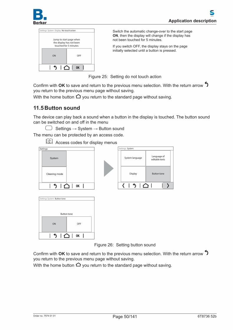
Switch the automatic change-over to the start page ON, then the display will change if the display has not been touched for 5 minutes.
If you switch OFF, the display stays on the page initially selected until a button is pressed.
Figure 25: Setting do not touch action
ConfirmwithOK to save and return to the previous menu selection. With the return arrow you return to the previous menu page without saving.With the home button you return to the standard page without saving.
11.5 Button soundThe device can play back a sound when a button in the display is touched. The button sound can be switched on and off in the menu
Settings→System→ButtonsoundThe menu can be protected by an access code.
ETS Access codes for display menus
Cleaning mode
Settings
System
Button toneDisplay
Language ofeditable texts
System language
Settings System
OFFON
Button tone
Settings System Button tone
Figure 26: Setting button sound
ConfirmwithOK to save and return to the previous menu selection. With the return arrow you return to the previous menu page without saving.With the home button you return to the standard page without saving.
Application description
Page 50/141Order no. 7574 01 01 6T8736 52b
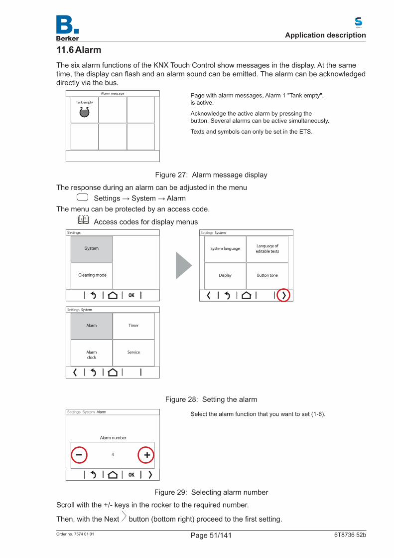
11.6 AlarmThe six alarm functions of the KNX Touch Control show messages in the display. At the same time,thedisplaycanflashandanalarmsoundcanbeemitted.Thealarmcanbeacknowledgeddirectly via the bus.
Tank empty
Alarm message
Page with alarm messages, Alarm 1 "Tank empty", is active.
Acknowledge the active alarm by pressing the button. Several alarms can be active simultaneously.
Texts and symbols can only be set in the ETS.
Figure 27: Alarm message display
The response during an alarm can be adjusted in the menu Settings→System→Alarm
The menu can be protected by an access code.ETS Access codes for display menus
Cleaning mode
Settings
System
Button toneDisplay
Language ofeditable texts
System language
Settings System
ServiceAlarmclock
TimerAlarm
Settings System
Figure 28: Setting the alarm
– +
Alarm number
Settings System Alarm
4
Select the alarm function that you want to set (1-6).
Figure 29: Selecting alarm number
Scrollwiththe+/-keysintherockertotherequirednumber.
Then, with the Next button(bottomright)proceedtothefirstsetting.
Application description
Page 51/141Order no. 7574 01 01 6T8736 52b
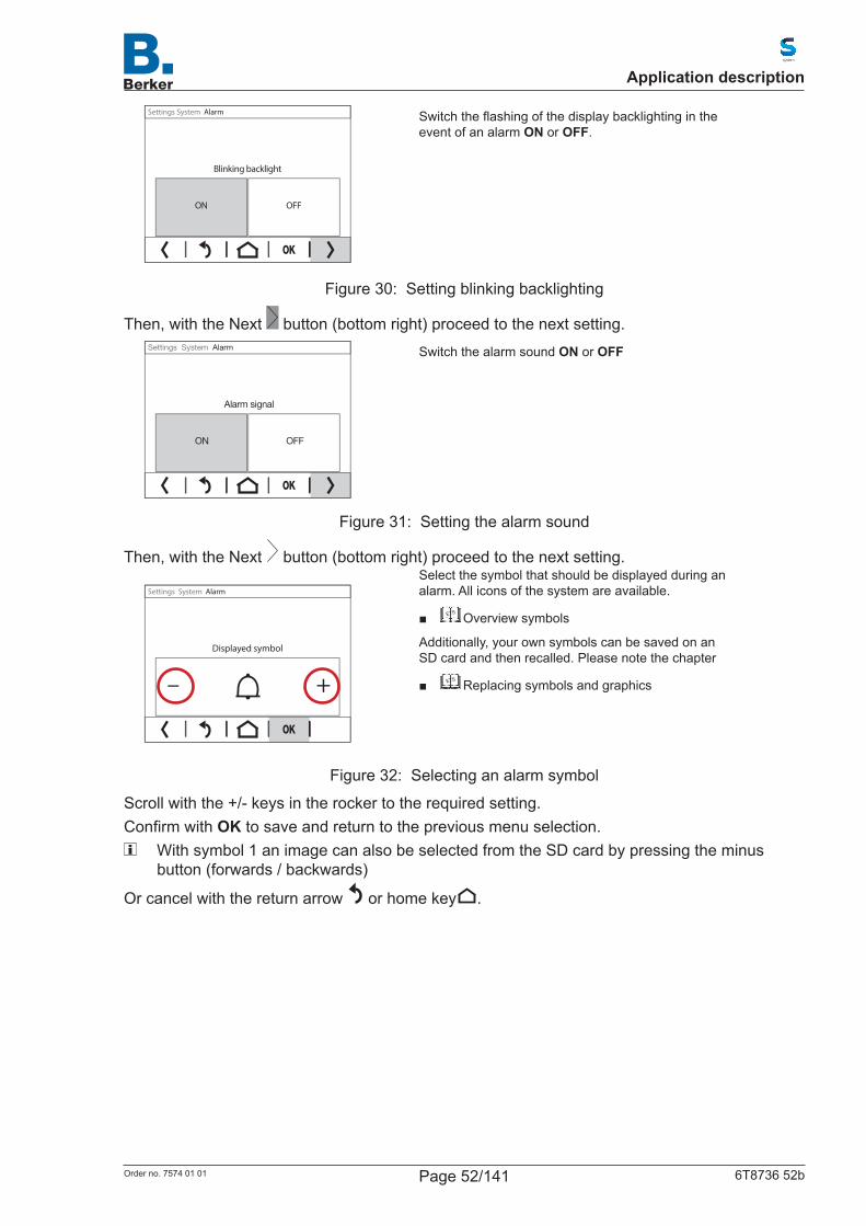
OFFON
Blinking backlight
Settings System Alarm
Switchtheflashingofthedisplaybacklightingintheevent of an alarm ON or OFF.
Figure 30: Setting blinking backlighting
Then, with the Next button (bottom right) proceed to the next setting.
OFFON
Alarm signal
Settings System Alarm
Switch the alarm sound ON or OFF
Figure 31: Setting the alarm sound
Then, with the Next button (bottom right) proceed to the next setting.
– +
Displayed symbol
Settings System Alarm
Select the symbol that should be displayed during an alarm. All icons of the system are available.
■ ETS Overview symbols
Additionally, your own symbols can be saved on an SD card and then recalled. Please note the chapter
■ ETS Replacing symbols and graphics
Figure 32: Selecting an alarm symbol
Scrollwiththe+/-keysintherockertotherequiredsetting.ConfirmwithOK to save and return to the previous menu selection.
With symbol 1 an image can also be selected from the SD card by pressing the minus button (forwards / backwards)
Or cancel with the return arrow or home key .
Application description
Page 52/141Order no. 7574 01 01 6T8736 52b
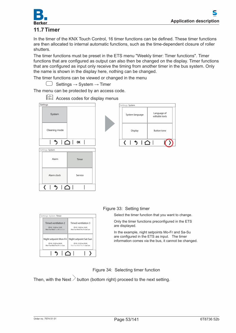
11.7 TimerInthetimeroftheKNXTouchControl,16timerfunctionscanbedefined.Thesetimerfunctionsare then allocated to internal automatic functions, such as the time-dependent closure of roller shutters. The timer functions must be preset in the ETS menu "Weekly timer: Timer functions". Timer functionsthatareconfiguredasoutputcanalsothenbechangedonthedisplay.Timerfunctionsthatareconfiguredasinputonlyreceivethetimingfromanothertimerinthebussystem.Onlythe name is shown in the display here, nothing can be changed.The timer functions can be viewed or changed in the menu
Settings→System→TimerThe menu can be protected by an access code.
ETS Access codes for display menus
Cleaning mode
Settings
System
Button toneDisplay
Language ofeditable texts
System language
Settings System
Alarm clock Service
Alarm Timer
Settings System
Figure 33: Setting timer
Night setpoint Mon-Fri
ZR 04 22:00 to 06:00Mon Tue Wed Thu Fri Sat Sun
Night setpoint Sat-Sun
ZR 05 23:30 to 09:00Mon Tue Wed Thu Fri Sat Sun
Timed ventilation 3
ZR 03 18:00 to 18:05Mon Tue Wed Thu Fri Sat Sun
Timed ventilation 2
ZR 02 12:00 to 12:05Mon Tue Wed Thu Fri Sat Sun
Settings System Timer
Select the timer function that you want to change.
OnlythetimerfunctionspreconfiguredintheETSare displayed.
In the example, night setpoints Mo-Fr and Sa-Su areconfiguredintheETSasinput.Thetimerinformation comes via the bus, it cannot be changed.
Figure 34: Selecting timer function
Then, with the Next button (bottom right) proceed to the next setting.
Application description
Page 53/141Order no. 7574 01 01 6T8736 52b
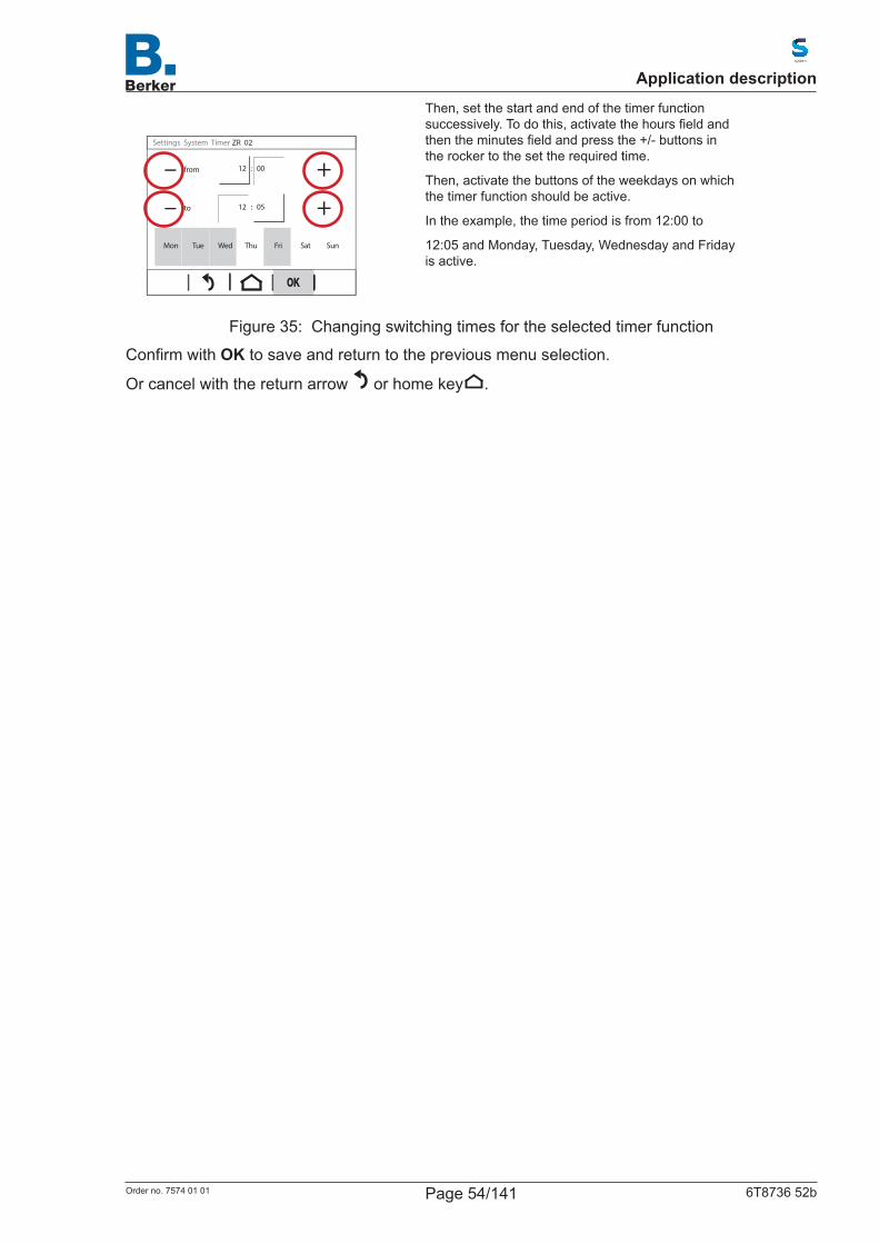
– +
– +
Mon Tue Wed Thu Fri Sat Sun
to
from
Settings System Timer ZR 02
12 : 05
12 : 00
Then, set the start and end of the timer function successively.Todothis,activatethehoursfieldandthentheminutesfieldandpressthe+/-buttonsintherockertothesettherequiredtime.
Then, activate the buttons of the weekdays on which the timer function should be active.
In the example, the time period is from 12:00 to
12:05 and Monday, Tuesday, Wednesday and Friday is active.
Figure 35: Changing switching times for the selected timer function
ConfirmwithOK to save and return to the previous menu selection.
Or cancel with the return arrow or home key .
Application description
Page 54/141Order no. 7574 01 01 6T8736 52b
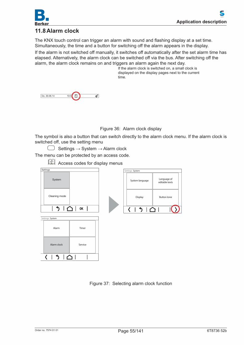
11.8 Alarm clockTheKNXtouchcontrolcantriggeranalarmwithsoundandflashingdisplayatasettime.Simultaneously, the time and a button for switching off the alarm appears in the display.If the alarm is not switched off manually, it switches off automatically after the set alarm time has elapsed. Alternatively, the alarm clock can be switched off via the bus. After switching off the alarm, the alarm clock remains on and triggers an alarm again the next day.
Do. 30.06.14 10:57
If the alarm clock is switched on, a small clock is displayed on the display pages next to the current time.
Figure 36: Alarm clock display
The symbol is also a button that can switch directly to the alarm clock menu. If the alarm clock is switched off, use the setting menu
Settings→System→AlarmclockThe menu can be protected by an access code.
ETS Access codes for display menus
Cleaning mode
Settings
System
Button toneDisplay
Language ofeditable texts
System language
Settings System
ServiceAlarm clock
TimerAlarm
Settings System
Figure 37: Selecting alarm clock function
Application description
Page 55/141Order no. 7574 01 01 6T8736 52b
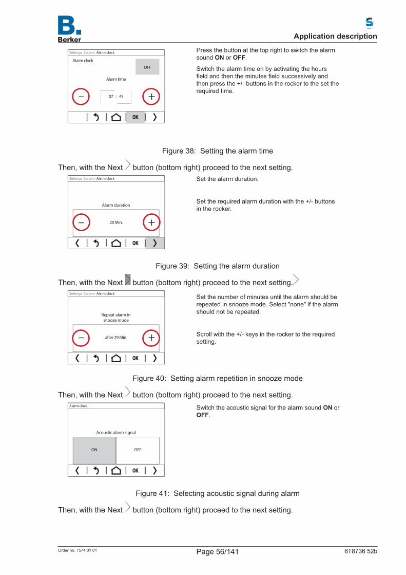
– +
Alarm time
OFFAlarm clock
Settings System Alarm clock
07 : 45
Press the button at the top right to switch the alarm sound ON or OFF.
Switch the alarm time on by activating the hours fieldandthentheminutesfieldsuccessivelyandthen press the +/- buttons in the rocker to the set the requiredtime.
Figure 38: Setting the alarm time
Then, with the Next button (bottom right) proceed to the next setting.
– +
Alarm duration
Settings System Alarm clock
20 Min.
Set the alarm duration.
Settherequiredalarmdurationwiththe+/-buttonsin the rocker.
Figure 39: Setting the alarm duration
Then, with the Next button (bottom right) proceed to the next setting.
– +
Repeat alarm in snooze mode
Settings System Alarm clock
after 29 Min.
Set the number of minutes until the alarm should be repeated in snooze mode. Select "none" if the alarm should not be repeated.
Scrollwiththe+/-keysintherockertotherequiredsetting.
Figure 40: Setting alarm repetition in snooze mode
Then, with the Next button (bottom right) proceed to the next setting.
ON OFF
Acoustic alarm signal
Alarm clock
Switch the acoustic signal for the alarm sound ON or OFF.
Figure 41: Selecting acoustic signal during alarm
Then, with the Next button (bottom right) proceed to the next setting.
Application description
Page 56/141Order no. 7574 01 01 6T8736 52b

ON OFF
Alarm screen �ashing
Alarm clock
Switchtheflashingofthedisplaybacklightingintheevent of an alarm ON or OFF.
Figure 42: Flashing display during alarm
ConfirmwithOK to save and return to the previous menu selection.
Or cancel with the return arrow or home key .
Application description
Page 57/141Order no. 7574 01 01 6T8736 52b
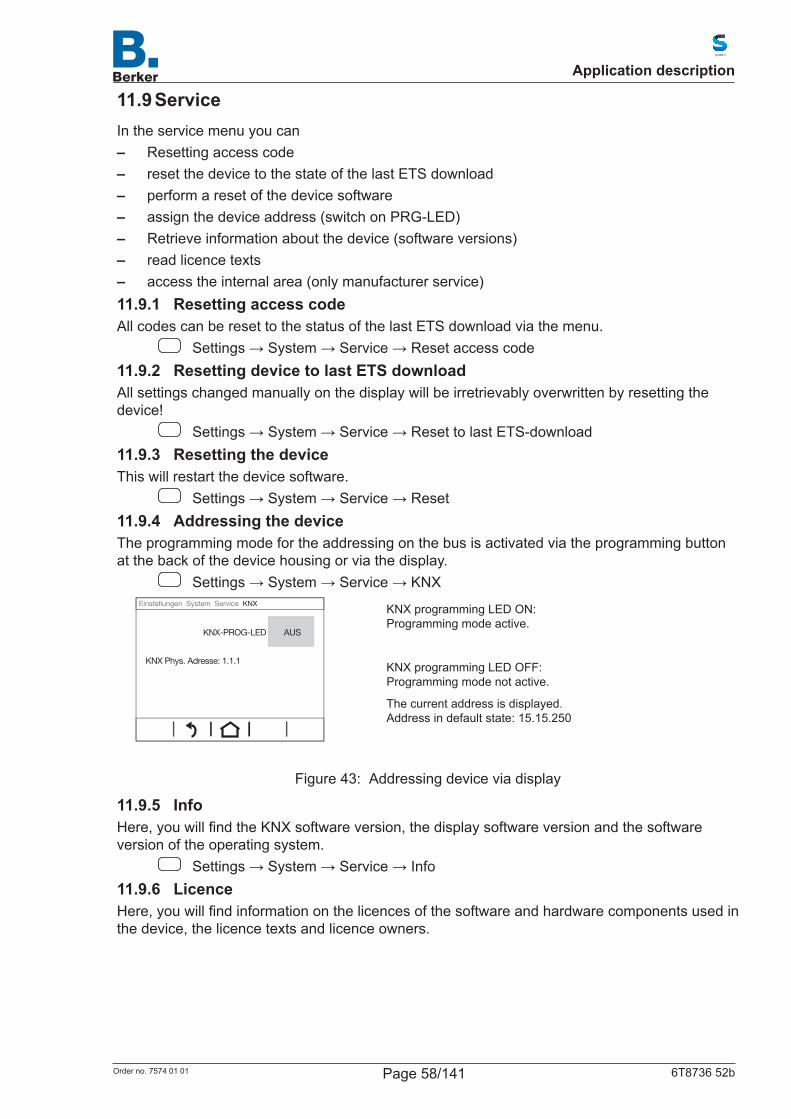
11.9 ServiceIn the service menu you can – Resetting access code – reset the device to the state of the last ETS download – perform a reset of the device software – assign the device address (switch on PRG-LED) – Retrieve information about the device (software versions) – read licence texts – access the internal area (only manufacturer service)
11.9.1 Resetting access codeAll codes can be reset to the status of the last ETS download via the menu.
Settings→System→Service→Resetaccesscode11.9.2 Resetting device to last ETS downloadAll settings changed manually on the display will be irretrievably overwritten by resetting the device!
Settings→System→Service→ResettolastETS-download11.9.3 Resetting the deviceThis will restart the device software.
Settings→System→Service→Reset11.9.4 Addressing the deviceThe programming mode for the addressing on the bus is activated via the programming button at the back of the device housing or via the display.
Settings→System→Service→KNX
KNX-PROG-LED
KNX Phys. Adresse: 1.1.1
AUS
Einstellungen System Service KNX
KNX programming LED ON: Programming mode active.
KNX programming LED OFF: Programming mode not active.
The current address is displayed. Address in default state: 15.15.250
Figure 43: Addressing device via display
11.9.5 InfoHere,youwillfindtheKNXsoftwareversion,thedisplaysoftwareversionandthesoftwareversion of the operating system.
Settings→System→Service→Info11.9.6 LicenceHere,youwillfindinformationonthelicencesofthesoftwareandhardwarecomponentsusedinthe device, the licence texts and licence owners.
Application description
Page 58/141Order no. 7574 01 01 6T8736 52b

12. ConfigurationofdisplaypagesThedeviceprovides10displaypagesthatcanbeconfiguredindividuallywith – surfaces (switches, display areas for sensor values) – Rockers – Control knobThirtysevenpredefinedpagedisplaysareprovidedforthispurpose.Thepagesareconfiguredin the ETS and then represented on the display.
12.1 Selecting pages on the displayOnlypagesconfiguredwiththeETSaredisplayed1to10pagescanbedisplayed.Theindividual pages are selected from the lower menu bar. The page selection is displayed in page blocks of 3-4 pages each. The page blocks are selected with the buttons . The underlying function is executed by pressing the touch control surface.
Page 5 Page 6 Page 7
Thu. 30.06.14 10:34
LIGHT BATHROOM
Off
Operable element
To previous page block Display "page 7"
To next page block
Figure 44: Selecting page on the display
AstartpageisdefinedintheETS.Thedisplayjumpstothispagewhenthehome button in the settings is pressed (and after restart). Additionally, you can set that the start page will be displayed if no input is made on the display after 5 minutes.
Application description
Page 59/141Order no. 7574 01 01 6T8736 52b

12.2 ConfigurationofpagesintheETSETS menu: Page 1...10
At the top right corner of each page the button for accessing the system settings can be displayed. If it is not desirable for the system to be set by the user, the button can be hidden. If, however, the system settings should be carried out on the display, then the button should be activated on one display page at least.
Menu navigation out of this page ActiveNot active
Table 41: Page navigation
Youcanassignanaccesscodeforthedisplaypagesonthescreen.Thecodeisrequestedwhen you switch between the pages. Thus, the standard page is always accessible.Specify whether the settings for the access code should be transferred from the ETS during downloading. The previous settings will then be overwritten – even changes made to the code on the display.
Transfer during download:Overwrite following parameter values during download Active
Not activeAccess code(1 … 8 numbers from 0 to 9)
[Free text]Empty field means no code request
Table 42: General setting of page navigation
Assign a name for this page. A name can be input (max. 15 characters) for each of the six possible languages. This name will appear in the lower menu bar of the screen.
ETS Language of the editable texts
Page nameLanguage selection 1...6 [Free text]
Table 43: Selecting a language for page name
Definethefunctionsofthepage.Apagecancontainfunctionalelementsconsistingofsurfaces(buttons), rockers, rotary controls or combinations of these elements. For this purpose, predefinedlayoutsareprovidedforthepagesettings.Thesecanbeselectedindividuallyforeach display page.Select the layout of the page using the table.
ETS Overviewofpredefinedpages
Page type seeoverviewofpredefinedpages
Table 44: Selecting page type
Symbols and labelling of the individual page elements can be customised.
Application description
Page 60/141Order no. 7574 01 01 6T8736 52b
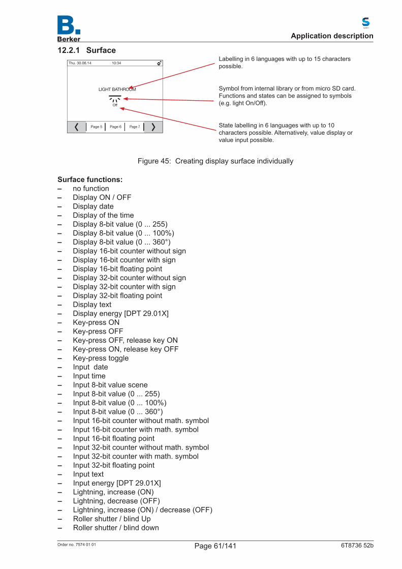
12.2.1 Surface
Page 5 Page 6 Page 7
Thu. 30.06.14 10:34
LIGHT BATHROOM
Off
Labelling in 6 languages with up to 15 characters possible.
Symbol from internal library or from micro SD card. Functions and states can be assigned to symbols (e.g. light On/Off).
State labelling in 6 languages with up to 10 characters possible. Alternatively, value display or value input possible.
Figure 45: Creating display surface individually
Surface functions: – no function – Display ON / OFF – Display date – Display of the time – Display 8-bit value (0 ... 255) – Display 8-bit value (0 ... 100%) – Display 8-bit value (0 ... 360°) – Display 16-bit counter without sign – Display 16-bit counter with sign – Display16-bitfloatingpoint – Display 32-bit counter without sign – Display 32-bit counter with sign – Display32-bitfloatingpoint – Display text – Display energy [DPT 29.01X] – Key-press ON – Key-press OFF – Key-press OFF, release key ON – Key-press ON, release key OFF – Key-press toggle – Input date – Input time – Input 8-bit value scene – Input 8-bit value (0 ... 255) – Input 8-bit value (0 ... 100%) – Input 8-bit value (0 ... 360°) – Input 16-bit counter without math. symbol – Input 16-bit counter with math. symbol – Input16-bitfloatingpoint – Input 32-bit counter without math. symbol – Input 32-bit counter with math. symbol – Input32-bitfloatingpoint – Input text – Input energy [DPT 29.01X] – Lightning, increase (ON) – Lightning, decrease (OFF) – Lightning, increase (ON) / decrease (OFF) – Roller shutter / blind Up – Roller shutter / blind down
Application description
Page 61/141Order no. 7574 01 01 6T8736 52b
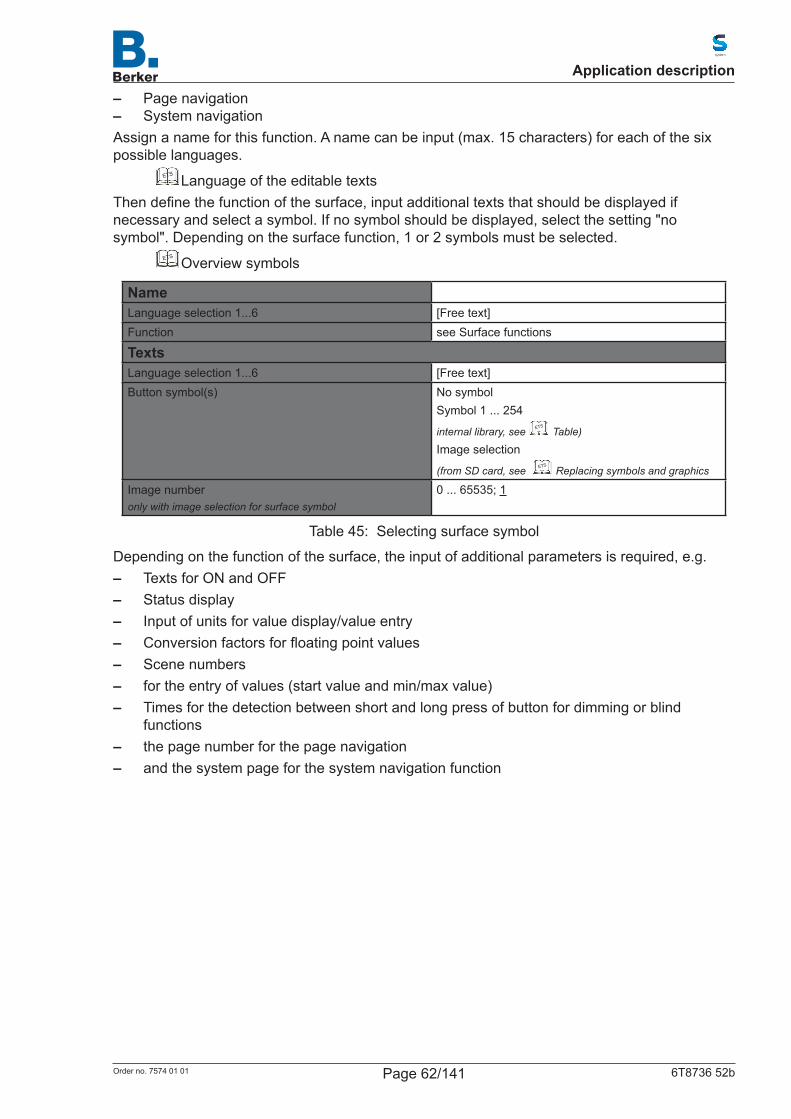
– Page navigation – System navigation
Assign a name for this function. A name can be input (max. 15 characters) for each of the six possible languages.
ETS Language of the editable textsThendefinethefunctionofthesurface,inputadditionaltextsthatshouldbedisplayedifnecessary and select a symbol. If no symbol should be displayed, select the setting "no symbol". Depending on the surface function, 1 or 2 symbols must be selected.
ETS Overview symbols
NameLanguage selection 1...6 [Free text]Function see Surface functions
TextsLanguage selection 1...6 [Free text]Button symbol(s) No symbol
Symbol 1 ... 254
internal library, see ETS
Table)
Image selection
(from SD card, see ETS
Replacing symbols and graphics
Image numberonly with image selection for surface symbol
0 ... 65535; 1
Table 45: Selecting surface symbol
Dependingonthefunctionofthesurface,theinputofadditionalparametersisrequired,e.g. – Texts for ON and OFF – Status display – Input of units for value display/value entry – Conversionfactorsforfloatingpointvalues – Scene numbers – for the entry of values (start value and min/max value) – Times for the detection between short and long press of button for dimming or blind
functions – the page number for the page navigation – and the system page for the system navigation function
Application description
Page 62/141Order no. 7574 01 01 6T8736 52b
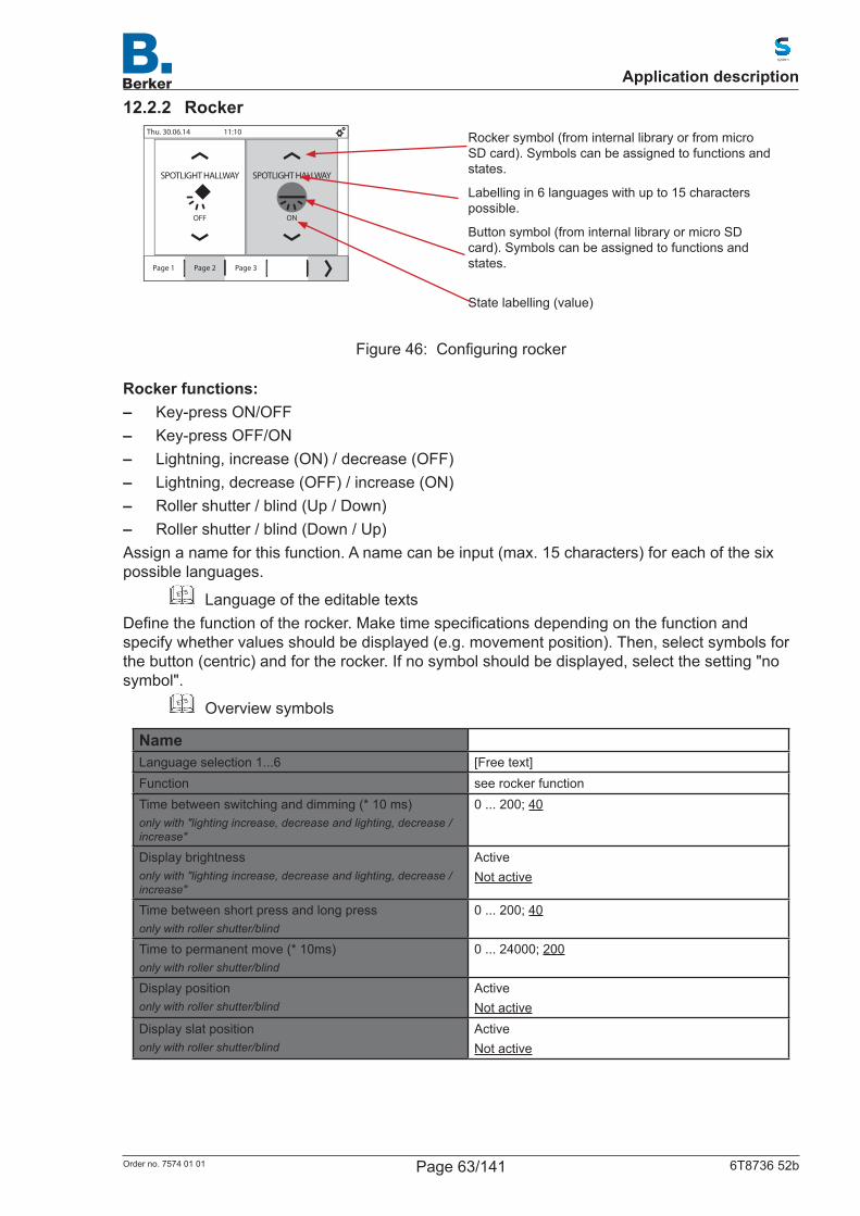
12.2.2 Rocker
Page 1 Page 2 Page 3
Thu. 30.06.14 11:10
ON
SPOTLIGHT HALLWAY
OFF
SPOTLIGHT HALLWAY
Rocker symbol (from internal library or from micro SD card). Symbols can be assigned to functions and states.
Labelling in 6 languages with up to 15 characters possible.
Button symbol (from internal library or micro SD card). Symbols can be assigned to functions and states.
State labelling (value)
Figure 46: Configuringrocker
Rocker functions: – Key-press ON/OFF – Key-press OFF/ON – Lightning, increase (ON) / decrease (OFF) – Lightning, decrease (OFF) / increase (ON) – Roller shutter / blind (Up / Down) – Roller shutter / blind (Down / Up)
Assign a name for this function. A name can be input (max. 15 characters) for each of the six possible languages.
ETS Language of the editable textsDefinethefunctionoftherocker.Maketimespecificationsdependingonthefunctionandspecify whether values should be displayed (e.g. movement position). Then, select symbols for the button (centric) and for the rocker. If no symbol should be displayed, select the setting "no symbol".
ETS Overview symbols
NameLanguage selection 1...6 [Free text]Function see rocker functionTime between switching and dimming (* 10 ms)only with "lighting increase, decrease and lighting, decrease / increase"
0 ... 200; 40
Display brightnessonly with "lighting increase, decrease and lighting, decrease / increase"
ActiveNot active
Time between short press and long press only with roller shutter/blind
0 ... 200; 40
Time to permanent move (* 10ms)only with roller shutter/blind
0 ... 24000; 200
Display positiononly with roller shutter/blind
ActiveNot active
Display slat positiononly with roller shutter/blind
ActiveNot active
Application description
Page 63/141Order no. 7574 01 01 6T8736 52b
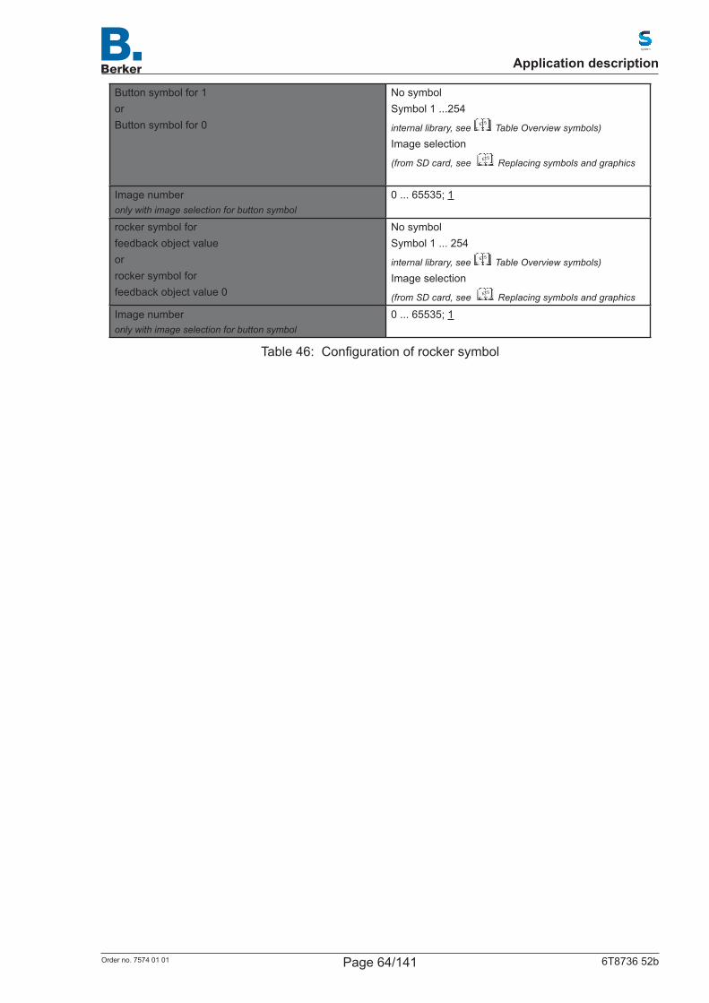
Button symbol for 1orButton symbol for 0
No symbolSymbol 1 ...254
internal library, see ETS
Table Overview symbols)
Image selection
(from SD card, see ETS
Replacing symbols and graphics
Image numberonly with image selection for button symbol
0 ... 65535; 1
rocker symbol forfeedback object value orrocker symbol forfeedback object value 0
No symbolSymbol 1 ... 254
internal library, see ETS
Table Overview symbols)
Image selection
(from SD card, see ETS
Replacing symbols and graphics
Image numberonly with image selection for button symbol
0 ... 65535; 1
Table 46: Configurationofrockersymbol
Application description
Page 64/141Order no. 7574 01 01 6T8736 52b
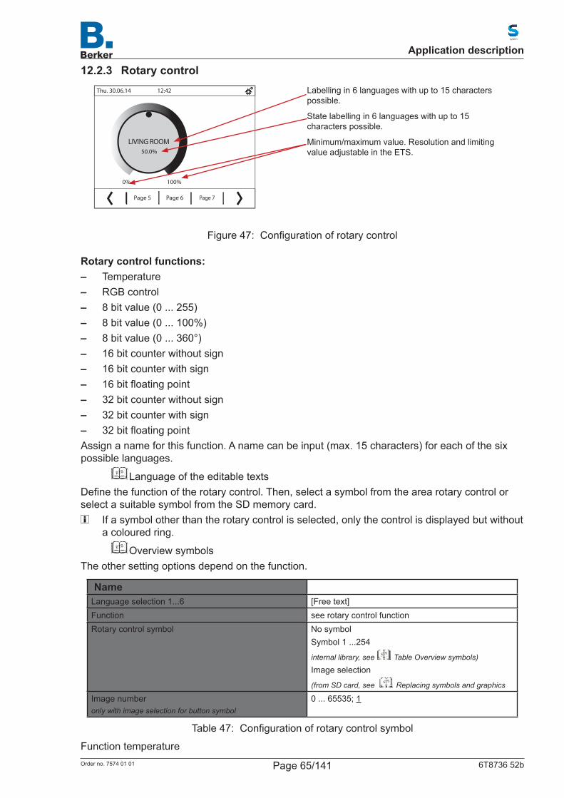
12.2.3 Rotary control
Page 5 Page 6 Page 7
Thu. 30.06.14 12:42
100%0%
50.0%
LIVING ROOM
Labelling in 6 languages with up to 15 characters possible.
State labelling in 6 languages with up to 15 characters possible.
Minimum/maximum value. Resolution and limiting value adjustable in the ETS.
Figure 47: Configurationofrotarycontrol
Rotary control functions: – Temperature – RGB control – 8 bit value (0 ... 255) – 8 bit value (0 ... 100%) – 8 bit value (0 ... 360°) – 16 bit counter without sign – 16 bit counter with sign – 16bitfloatingpoint – 32 bit counter without sign – 32 bit counter with sign – 32bitfloatingpoint
Assign a name for this function. A name can be input (max. 15 characters) for each of the six possible languages.
ETS Language of the editable textsDefinethefunctionoftherotarycontrol.Then,selectasymbolfromthearearotarycontrolorselect a suitable symbol from the SD memory card.
If a symbol other than the rotary control is selected, only the control is displayed but without a coloured ring.
ETS Overview symbolsThe other setting options depend on the function.
NameLanguage selection 1...6 [Free text]Function see rotary control functionRotary control symbol No symbol
Symbol 1 ...254
internal library, see ETS
Table Overview symbols)
Image selection
(from SD card, see ETS
Replacing symbols and graphics
Image numberonly with image selection for button symbol
0 ... 65535; 1
Table 47: Configurationofrotarycontrolsymbol
Function temperature
Application description
Page 65/141Order no. 7574 01 01 6T8736 52b
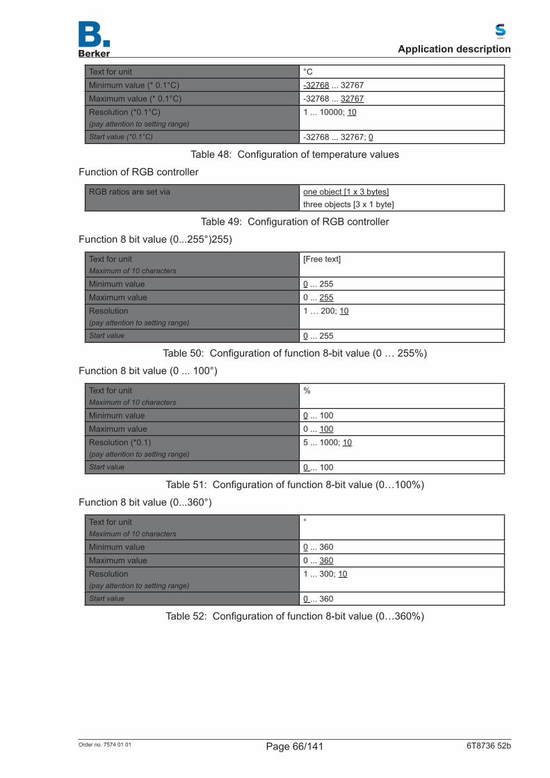
Text for unit °CMinimum value (* 0.1°C) -32768 ... 32767Maximum value (* 0.1°C) -32768 ... 32767Resolution (*0.1°C)(pay attention to setting range)
1 ... 10000; 10
Start value (*0.1°C) -32768 ... 32767; 0
Table 48: Configurationoftemperaturevalues
Function of RGB controller
RGB ratios are set via one object [1 x 3 bytes]three objects [3 x 1 byte]
Table 49: ConfigurationofRGBcontroller
Function 8 bit value (0...255°)255)
Text for unitMaximum of 10 characters
[Free text]
Minimum value 0 ... 255Maximum value 0 ... 255Resolution(pay attention to setting range)
1 … 200; 10
Start value 0 ... 255
Table 50: Configurationoffunction8-bitvalue(0…255%)
Function 8 bit value (0 ... 100°)
Text for unitMaximum of 10 characters
%
Minimum value 0 ... 100Maximum value 0 ... 100Resolution (*0.1)(pay attention to setting range)
5 ... 1000; 10
Start value 0 ... 100
Table 51: Configurationoffunction8-bitvalue(0…100%)
Function 8 bit value (0...360°)
Text for unitMaximum of 10 characters
°
Minimum value 0 ... 360Maximum value 0 ... 360Resolution(pay attention to setting range)
1 ... 300; 10
Start value 0 ... 360
Table 52: Configurationoffunction8-bitvalue(0…360%)
Application description
Page 66/141Order no. 7574 01 01 6T8736 52b
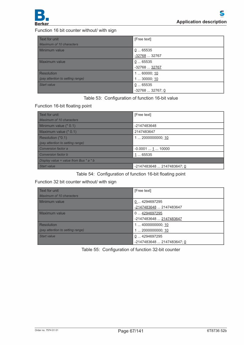
Function 16 bit counter without/ with sign
Text for unitMaximum of 10 characters
[Free text]
Minimum value 0 ... 65535-32768 ... 32767
Maximum value 0 ... 65535-32768 ... 32767
Resolution(pay attention to setting range)
1 ... 60000; 101 ... 30000; 10
Start value 0 ... 65535-32768 ... 32767; 0
Table 53: Configurationoffunction16-bitvalue
Function16-bitfloatingpoint
Text for unitMaximum of 10 characters
[Free text]
Minimum value (* 0.1) -2147483648Maximum value (* 0.1) 2147483647Resolution (*0.1)(pay attention to setting range)
1 ... 2000000000; 10
Conversion factor a -0.0001 ... 1 ... 10000Conversion factor b 1 ... 65535Display value = value from Bus * a * b
Start value -2147483648 ... 2147483647; 0
Table 54: Configurationoffunction16-bitfloatingpoint
Function 32 bit counter without/ with sign
Text for unitMaximum of 10 characters
[Free text]
Minimum value 0 ... 4294697295-2147483648 ... 2147483647
Maximum value 0 ... 4294697295-2147483648 ... 2147483647
Resolution(pay attention to setting range)
1 ... 4000000000; 101 ... 2000000000; 10
Start value 0 ... 4294697295 -2147483648 ... 2147483647; 0
Table 55: Configurationoffunction32-bitcounter
Application description
Page 67/141Order no. 7574 01 01 6T8736 52b
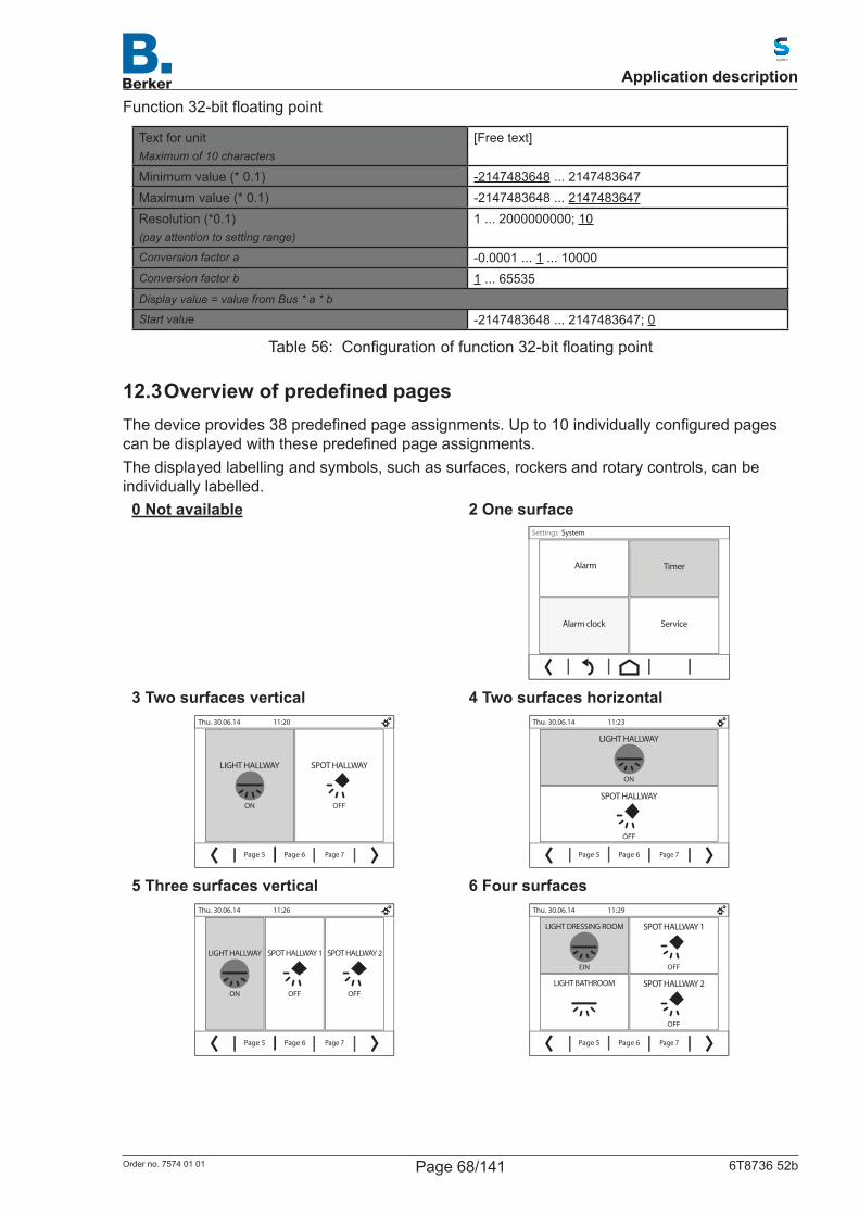
Function32-bitfloatingpoint
Text for unitMaximum of 10 characters
[Free text]
Minimum value (* 0.1) -2147483648 ... 2147483647Maximum value (* 0.1) -2147483648 ... 2147483647Resolution (*0.1)(pay attention to setting range)
1 ... 2000000000; 10
Conversion factor a -0.0001 ... 1 ... 10000Conversion factor b 1 ... 65535Display value = value from Bus * a * b
Start value -2147483648 ... 2147483647; 0
Table 56: Configurationoffunction32-bitfloatingpoint
12.3 OverviewofpredefinedpagesThedeviceprovides38predefinedpageassignments.Upto10individuallyconfiguredpagescanbedisplayedwiththesepredefinedpageassignments.The displayed labelling and symbols, such as surfaces, rockers and rotary controls, can be individually labelled.
0 Not available 2 One surface
Alarm clock Service
Alarm Timer
Settings System
3 Two surfaces vertical
Page 5 Page 6 Page 7
Thu. 30.06.14 11:20
ON
LIGHT HALLWAY
OFF
SPOT HALLWAY
4 Two surfaces horizontal
Page 5 Page 6 Page 7
Thu. 30.06.14 11:23
ON
LIGHT HALLWAY
OFF
SPOT HALLWAY
5 Three surfaces verticalThu. 30.06.14 11:26
ON
LIGHT HALLWAY
OFF
SPOT HALLWAY 2
OFF
SPOT HALLWAY 1
Page 7Page 5 Page 6
6 Four surfaces
Page 5 Page 6 Page 7
EIN
LIGHT DRESSING ROOM
LIGHT BATHROOM
OFF
SPOT HALLWAY 1
OFF
Thu. 30.06.14 11:29
SPOT HALLWAY 2
Application description
Page 68/141Order no. 7574 01 01 6T8736 52b
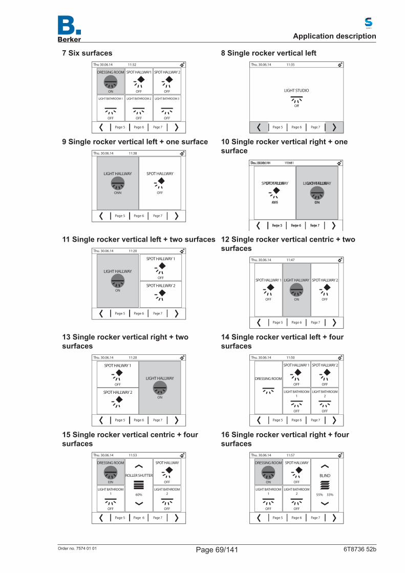
7 Six surfacesThu 30.06.14 11:32
ON
DRESSING ROOM
OFF
LIGHT BATHROOM 1
OFF
LIGHT BATHROOM 2
OFF
LIGHT BATHROOM 3
OFF
SPOT HALLWAY 2
OFF
SPOT HALLWAY1
Page 5 Page 7Page 6
8 Single rocker vertical left
Page 6 Page 7
Thu. 30.06.14 11:35
LIGHT STUDIO
O�
Page 5
9 Single rocker vertical left + one surface
Page 5 Page 6 Page 7
Thu. 30.06.14 11:38
ONN
LIGHT HALLWAY
OFF
SPOT HALLWAY
10 Single rocker vertical right + one surface
Page 5 Page 6 Page 7
Thu. 30.06.14 11:41
ON
LIGHT HALLWAY
OFF
SPOT HALLWAY
Seite 5 Seite 6 Seite 7
Do. 30.06.14 11:41
EIN
LICHT FLUR
AUS
SPOT FLUR
11 Single rocker vertical left + two surfaces
Page 5 Page 6 Page 7
Thu. 30.06.14 11:20
ON
LIGHT HALLWAYOFF
SPOT HALLWAY 1
SPOT HALLWAY 2
12 Single rocker vertical centric + two surfaces
Page 5
Thu. 30.06.14 11:47
ON
LIGHT HALLWAY
OFF
SPOT HALLWAY 2
OFF
SPOT HALLWAY 1
Page 6 Page 7
13 Single rocker vertical right + two surfaces
Page 5 Page 6 Page 7
Thu. 30.06.14 11:20
ON
LIGHT HALLWAYOFF
SPOT HALWAY 1
SPOT HALLWAY 2
14 Single rocker vertical left + four surfaces
Page 5 Page 6 Page 7
Thu. 30.06.14 11:50
DRESSING ROOM
OFF
LIGHT BATHROOM 2
OFF
LIGHT BATHROOM 1
OFF
SPOT HALLWAY 2
OFF
SPOT HALLWAY 1
15 Single rocker vertical centric + four surfaces
Page 5 Page 6 Page 7
Thu. 30.06.14 11:53
EIN
DRESSING ROOM
OFF
LIGHT BATHROOM 2
OFF
LIGHT BATHROOM 1
OFF
SPOT HALLWAY
60%
ROLLER SHUTTER
16 Single rocker vertical right + four surfaces
Page 5 Page 6 Page 7
Thu. 30.06.14 11:57
55% 33%
BLINDON
DRESSING ROOM
OFF
LIGHT BATHROOM 2
OFF
LIGHT BATHROOM 1
OFF
SPOT HALLWAY
Application description
Page 69/141Order no. 7574 01 01 6T8736 52b

17 Dual rocker vertical
Page 5 Page 6 Page 7
Thu. 30.06.14 12:00
65%
LIGHT HALLWAY
45%
SPOT HALLWAY
18 Dual rocker vertical + one surface left
Seite 5 Seite 6 Seite 7
Do. 30.06.14 12:03
AUS
ANKLEIDE
55% 33%
JALOUSIE
60%
ROLLADEN
19 Dual rocker vertical + one surface centric
Seite 5 Seite 6 Seite 7
Do. 30.06.14 12:06
55%
ANKLEIDE
EIN
LICHT BAD
55% 33%
JALOUSIE
20 dual rocker vertical + one surface rightThu. 30.06.14 12:09
55%
DRESSING ROOM
ON
LIGHT BATHROOM
55% 33%
BLIND
Page 5 Page6 Page 7
21 Dual rocker vertical + two surfaces left
Page 5 Page 6 Page 7
55% 33%
BLIND
60%
ROLLER SHUTTER
ON
DRESSING ROOM
OFF
LIGHT BATHROOM
Thu. 30.06.14 12:12
22 Dual rocker vertical + two surfaces centric
Page 5 Page 6 Page 7
Thu. 30.06.14 12:15
55% 33%
BLIND
60%
ROLLER SHUTTER
ON
DRESSING ROOM
OFF
LIGHT BATHROOM
23 Dual rocker vertical + two surfaces right
Page 5 Page 6 Page 7
Thu. 30.06.14 12:18
55% 33%
BLIND
60%
ROLLER SHUTTER
ON
DRESSING ROOM
OFF
LIGHT BATHROOM
24 Single rocker horizontal
– +
Page 5 Page 6 Page 7
Thu. 30.06.14 12:21
50%
AWNING
25 Single rocker horizontal top + one surface
Page 5 Page 6 Page 7
Thu. 30.06.14 12:24
OFF
SPOT HALLWAY
LIGHT HALLWAY
26 Single rocker horizontal bottom + one surface
Page 5 Page 6 Page 7
Thu. 30.06.14 12:27
80%
WINDOW HALLWAY
ON
LIGHT HALLWAY
Application description
Page 70/141Order no. 7574 01 01 6T8736 52b

27 Single rocker horizontal top + three surfaces
Page 5 Page 6 Page 7
Thu. 30.06.14 12:30
20%
WINDOW HALLWAY
OFF
LIGHT HALLWAY 2
OFF
LIGHT HALLWAY 1
OFF
LIGHT WALL
28 Single rocker horizontal bottom + three surfaces
Page 5 Page 6 Page 7
Thu. 30.06.14 12:33
80%
WINDOW HALLWAY
OFF
LIGHT HALLWAY 2
ON
LIGHT HALLWAY 1
OFF
LIGHT WALL
29 Dual rocker horizontal
Page 5 Page 6 Page 7
tHU. 30.06.14 12:36
SPOT HALLWAY
70%
LIGHT HALLWAY
30 Triple rocker vertical
Page 5 Page 6 Page 7
Thu. 30.06.14 12:39
40%
DRESSING RROM
55% 33%
BLIND
60%
ROLLER SHUTTER
31 rotary control
Page 5 Page 6 Page 7
Thu. 30.06.14 12:42
100%0%
50.0%
LIVING ROOM
32 Rotary control + one surface vertical
Page 5 Page 6 Page 7
Thu. 30.06.14 12:45
100%0%
50.0%
LIGHT BATHROOM
OFF
LIGHT WALL
33 Rotary control + rocker
OPERATING MODE
Page 5 Page 6 Page 7
Thu. 30.06.14 12:48
35.0°C10.0°C
22.0°C
HEATING BATHROOM
34 Rotary control + one surface top
Page 5 Page 6 Page 7
Thu. 30.06.14 12:51
24.0°C16.0°C
20.0°C
LIVING ROOM
35 Rotary control + one surface bottom
OPERATING MODE
Page 5 Page 6 Page 7
Thu. 30.06.14 12:54
24.0°C16.0°C
20.0°C
LIVING ROOM
36 Rotary control + two surfaces right
OPERATING MODE
Page 5 Page 6 Page 7
Thu. 30.06.14 12:57
24.0°C16.0°C
20.0°C
LIVING ROOM
Application description
Page 71/141Order no. 7574 01 01 6T8736 52b
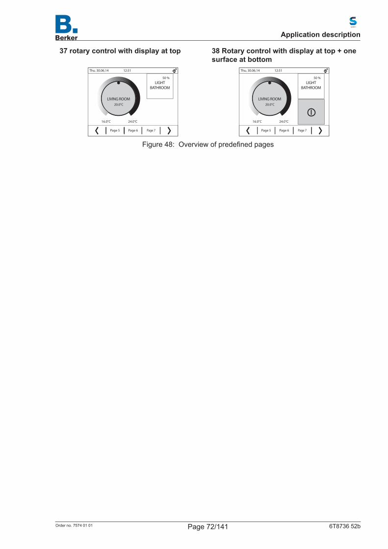
37 rotary control with display at top
Page 5 Page 6 Page 7
Thu. 30.06.14 12:51
24.0°C16.0°C
20.0°C
LIVING ROOM
LIGHT BATHROOM
50 %
38 Rotary control with display at top + one surface at bottom
Page 5 Page 6 Page 7
Thu. 30.06.14 12:51
24.0°C16.0°C
20.0°C
LIVING ROOM
LIGHT BATHROOM
50 %
Figure 48: Overviewofpredefinedpages
Application description
Page 72/141Order no. 7574 01 01 6T8736 52b
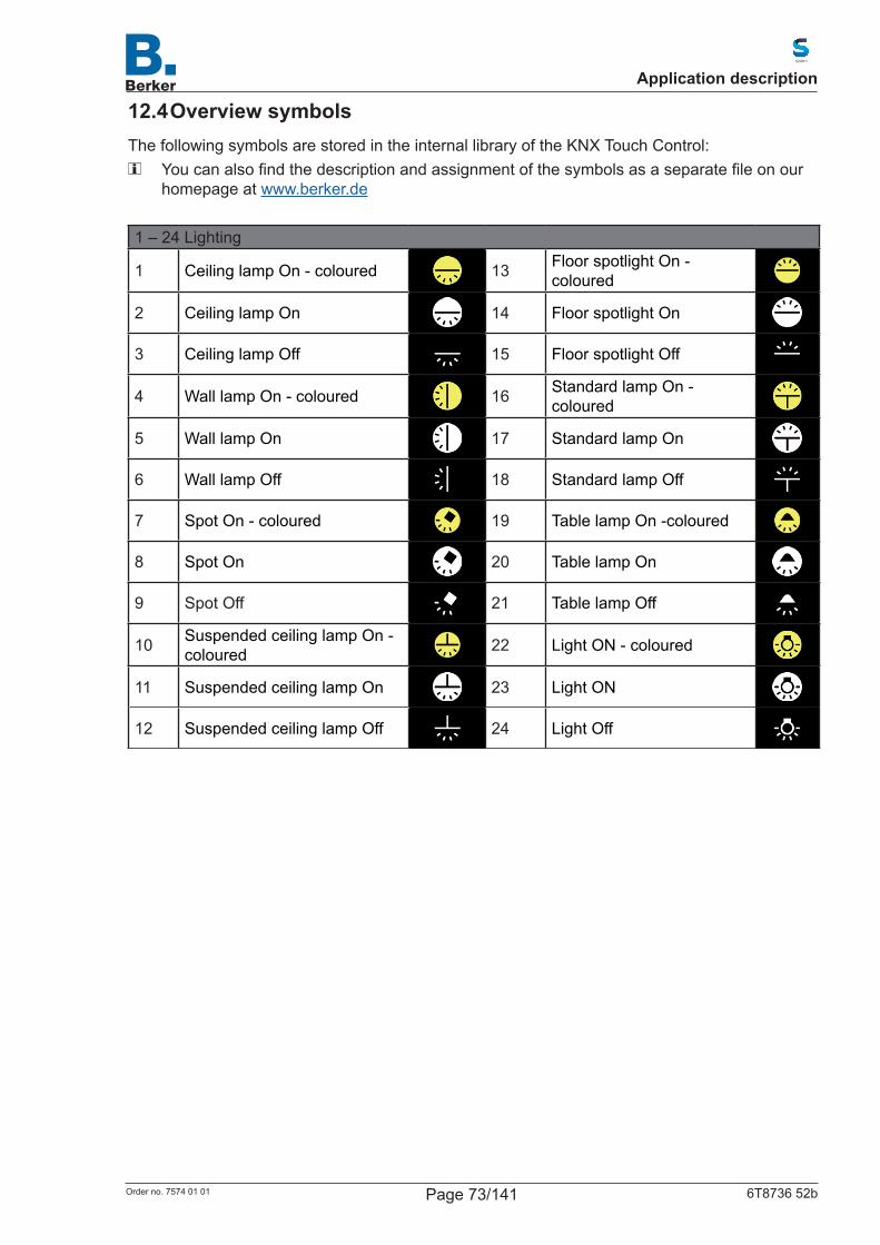
12.4 Overview symbolsThe following symbols are stored in the internal library of the KNX Touch Control: Youcanalsofindthedescriptionandassignmentofthesymbolsasaseparatefileonour
homepage at www.berker.de
1 – 24 Lighting
1 Ceiling lamp On - coloured 13 Floor spotlight On - coloured
2 Ceiling lamp On 14 Floor spotlight On
3 Ceiling lamp Off 15 Floor spotlight Off
4 Wall lamp On - coloured 16 Standard lamp On - coloured
5 Wall lamp On 17 Standard lamp On
6 Wall lamp Off 18 Standard lamp Off
7 Spot On - coloured 19 Table lamp On -coloured
8 Spot On 20 Table lamp On
9 Spot Off 21 Table lamp Off
10 Suspended ceiling lamp On - coloured 22 Light ON - coloured
11 Suspended ceiling lamp On 23 Light ON
12 Suspended ceiling lamp Off 24 Light Off
Application description
Page 73/141Order no. 7574 01 01 6T8736 52b
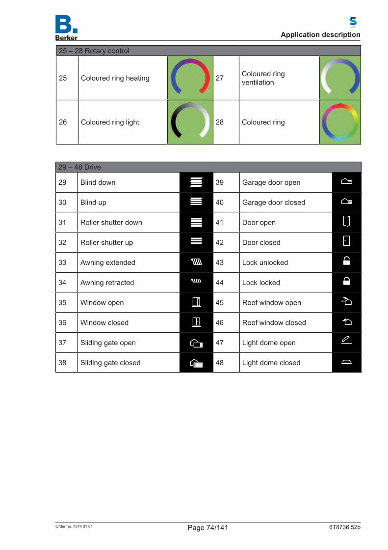
25 – 28 Rotary control
25 Coloured ring heating 27 Coloured ring ventilation
26 Coloured ring light 28 Coloured ring
29 – 48 Drive
29 Blind down 39 Garage door open
30 Blind up 40 Garage door closed
31 Roller shutter down 41 Door open
32 Roller shutter up 42 Door closed
33 Awning extended 43 Lock unlocked
34 Awning retracted 44 Lock locked
35 Window open 45 Roof window open
36 Window closed 46 Roof window closed
37 Sliding gate open 47 Light dome open
38 Sliding gate closed 48 Light dome closed
Application description
Page 74/141Order no. 7574 01 01 6T8736 52b
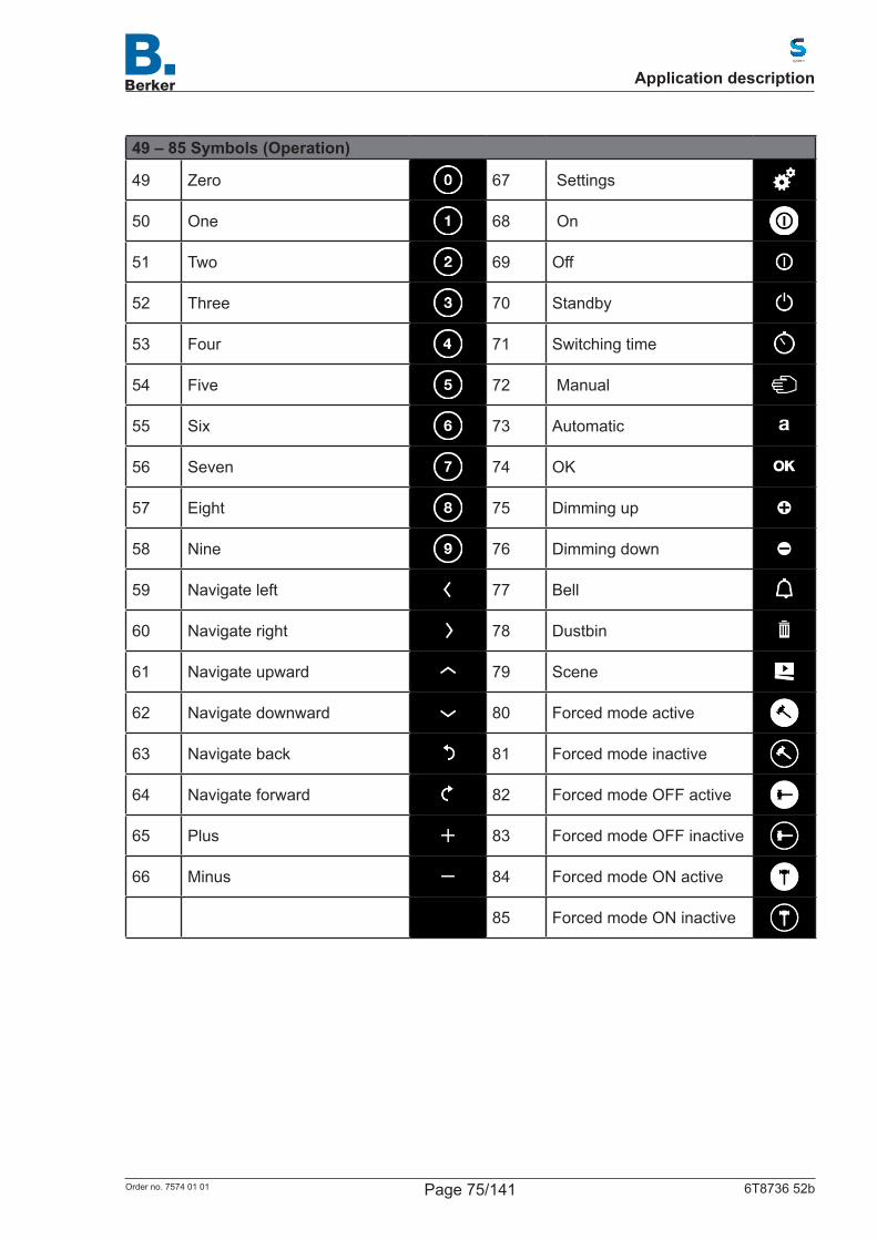
49 – 85 Symbols (Operation)
49 Zero 67 Settings
50 One 68 On
51 Two 69 Off
52 Three 70 Standby
53 Four 71 Switching time
54 Five 72 Manual
55 Six 73 Automatic
56 Seven 74 OK
57 Eight 75 Dimming up
58 Nine 76 Dimming down
59 Navigate left 77 Bell
60 Navigate right 78 Dustbin
61 Navigate upward 79 Scene
62 Navigate downward 80 Forced mode active
63 Navigate back 81 Forced mode inactive
64 Navigate forward 82 Forced mode OFF active
65 Plus 83 Forced mode OFF inactive
66 Minus 84 Forced mode ON active
85 Forced mode ON inactive
Application description
Page 75/141Order no. 7574 01 01 6T8736 52b
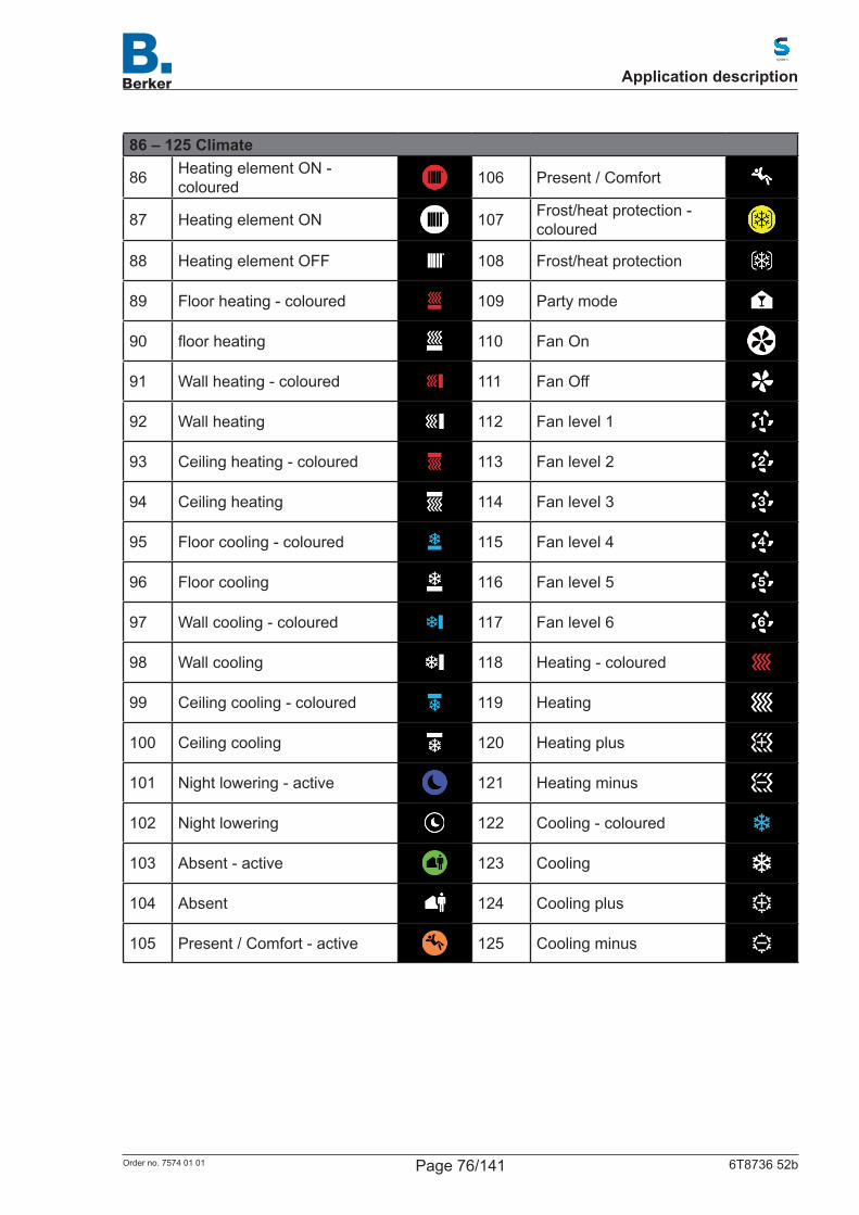
86 – 125 Climate
86 Heating element ON - coloured 106 Present / Comfort
87 Heating element ON 107 Frost/heat protection - coloured
88 Heating element OFF 108 Frost/heat protection
89 Floor heating - coloured 109 Party mode
90 floorheating 110 Fan On
91 Wall heating - coloured 111 Fan Off
92 Wall heating 112 Fan level 1
93 Ceiling heating - coloured 113 Fan level 2
94 Ceiling heating 114 Fan level 3
95 Floor cooling - coloured 115 Fan level 4
96 Floor cooling 116 Fan level 5
97 Wall cooling - coloured 117 Fan level 6
98 Wall cooling 118 Heating - coloured
99 Ceiling cooling - coloured 119 Heating
100 Ceiling cooling 120 Heating plus
101 Night lowering - active 121 Heating minus
102 Night lowering 122 Cooling - coloured
103 Absent - active 123 Cooling
104 Absent 124 Cooling plus
105 Present / Comfort - active 125 Cooling minus
Application description
Page 76/141Order no. 7574 01 01 6T8736 52b
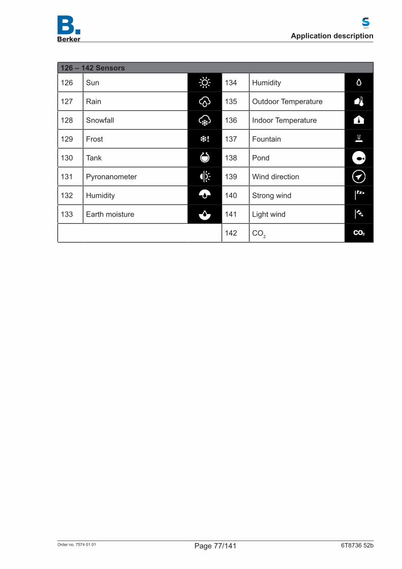
126 – 142 Sensors
126 Sun 134 Humidity
127 Rain 135 Outdoor Temperature
128 Snowfall 136 Indoor Temperature
129 Frost 137 Fountain
130 Tank 138 Pond
131 Pyronanometer 139 Wind direction
132 Humidity 140 Strong wind
133 Earth moisture 141 Light wind
142 CO2
Application description
Page 77/141Order no. 7574 01 01 6T8736 52b
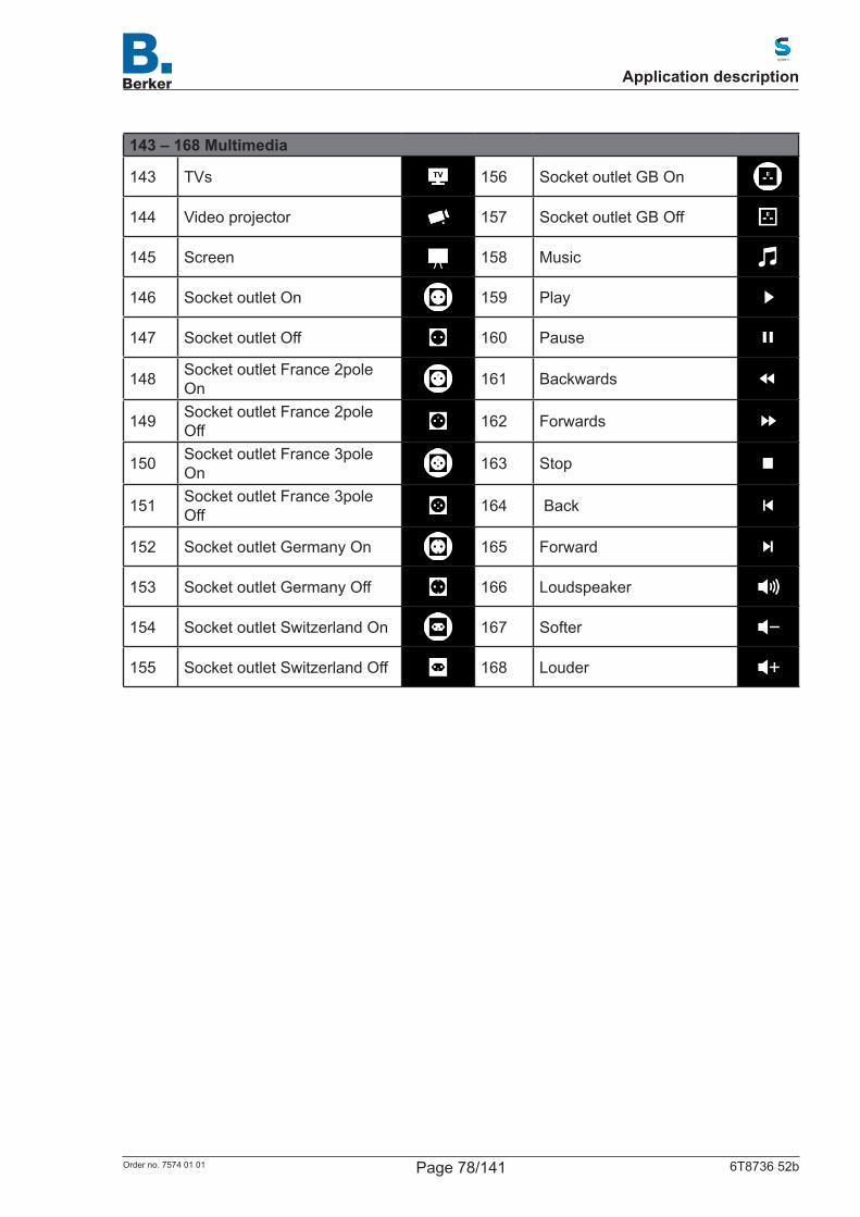
143 – 168 Multimedia
143 TVs 156 Socket outlet GB On
144 Video projector 157 Socket outlet GB Off
145 Screen 158 Music
146 Socket outlet On 159 Play
147 Socket outlet Off 160 Pause
148 Socket outlet France 2pole On 161 Backwards
149 Socket outlet France 2pole Off 162 Forwards
150 Socket outlet France 3pole On 163 Stop
151 Socket outlet France 3pole Off 164 Back
152 Socket outlet Germany On 165 Forward
153 Socket outlet Germany Off 166 Loudspeaker
154 Socket outlet Switzerland On 167 Softer
155 Socket outlet Switzerland Off 168 Louder
Application description
Page 78/141Order no. 7574 01 01 6T8736 52b

169 – 177 Safety
169 Motion detector 174 Siren outside armed
170 Siren 175 Siren armed
171 Attention 176 Siren outside
172 Open 177 Siren inside
173 Siren inside armed
178 – 193 House
178 House 186 Housekeeping
179 Dining room 187 Storage room
180 Lounge 188 Laundry
181 Kitchen 189 Toilet
182 Child's room 190 Office
183 Bathroom 191 Hallway
184 Bedroom 192 Carport
185 Dressing room 193 Garden
Table 57: Overviewofpredefinedsymbols
Application description
Page 79/141Order no. 7574 01 01 6T8736 52b
13. Automatic functions
13.1 Safety instructions regarding automatic functions
WARNING!Risk of injury from automatically moved components!The automatic control can cause components to start and endanger persons.No persons are allowed to stand in the range of movement of electromotively moved parts.Always disconnect the system for maintenance and cleaning from the power supply (e.g. switch off/remove fuse).
Appropriate building regulations must be complied with!
The guideline for power-operated windows, doors and gates BGR 232, among other things, must be complied with.
Rain alarm for automatically controlled windows:If rain starts, depending on the amount of rain and outside temperature, some time may pass until rain is detected by the sensors in the system. In addition, closure time must be taken into account for electrically powered windows or sliding roofs. Moisture-sensitive items should therefore not be placed in an area where they could be damaged by penetrating precipitation. Please also bear in mind that should a power failure occur when rain starts, for example, the windows will no longer be closed automatically if no emergency generator is installed.
Freezing over of guide rails of shadings:Please note that the guide rails of blinds, awnings and shutters that are mounted outside can freeze over. If a drive then moves, the shading and may be damaged.
13.2 General automatic settingsETS: Automatic
In the automatic menu, you assign the light, blind, awning, roller shutter, window, fan or thermostatfunctionstothefiveautomaticchannels.Furthermore, general parameters are set here: – Calculating the position of the sun – Monitoring wind and rain objects – Lock-up duration in the event of a wind alarm – Twilight threshold – Retraction and extension delays for shadings – Window opening restriction – Ventilation lock-up when cooling – Night-time re-cooling – Frost alarm – Heat protection temperature– Times for automatic restart
Application description
Page 80/141Order no. 7574 01 01 6T8736 52b
First determine whether or not the automatic control is used. If this setting is set to "not active", the automatic channels will be inactive even if assignments and settings have already been made.
Automatic Active Not active
Table 58: Activating/deactivating automatic function
Then,assigntherequiredfunctiontothefiveautomaticchannels.
Automatic 1 ... 5 do not useLight Blind Awningroller shuttersWindowExtractor fanThermostats
Table 59: Assigning function of the automatic(s)
13.2.1 Settings for position of the sunThe position of the sun is needed for controlling shadings. The information can be received via the corresponding communication objects or calculated in the device.
Position of the sun will calculatedreceived via communication objects
Type of solar position objectsonly if position of the sun is received via communication objects
2 byte4 byte
Table 60: Position of the sun function
The type of sun position objects (2 or 4 byte, only if position of the sun is calculated) is dependent on the device that transmits the corresponding values.If the position of the sun is not received via objects but is calculated, then the details of the location and time zone must be input. The location can be input by selecting a town or by specifying coordinates.
Application description
Page 81/141Order no. 7574 01 01 6T8736 52b
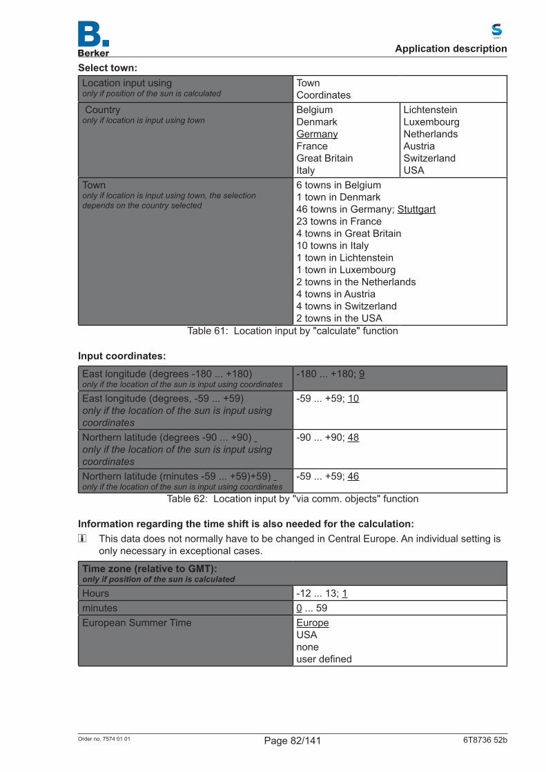
Select town:Location input usingonly if position of the sun is calculated
TownCoordinates
Countryonly if location is input using town
BelgiumDenmarkGermanyFranceGreat BritainItaly
LichtensteinLuxembourg NetherlandsAustria Switzerland USA
Townonly if location is input using town, the selection depends on the country selected
6 towns in Belgium1 town in Denmark46 towns in Germany; Stuttgart23 towns in France 4 towns in Great Britain10 towns in Italy 1 town in Lichtenstein1 town in Luxembourg 2 towns in the Netherlands 4 towns in Austria 4 towns in Switzerland 2 towns in the USA
Table 61: Location input by "calculate" function
Input coordinates:
East longitude (degrees -180 ... +180) only if the location of the sun is input using coordinates
-180 ... +180; 9
East longitude (degrees, -59 ... +59)only if the location of the sun is input using coordinates
-59 ... +59; 10
Northern latitude (degrees -90 ... +90) only if the location of the sun is input using coordinates
-90 ... +90; 48
Northern latitude (minutes -59 ... +59)+59) only if the location of the sun is input using coordinates
-59 ... +59; 46
Table 62: Location input by "via comm. objects" function
Information regarding the time shift is also needed for the calculation: This data does not normally have to be changed in Central Europe. An individual setting is
only necessary in exceptional cases.
Time zone (relative to GMT):only if position of the sun is calculated
Hours -12 ... 13; 1minutes 0 ... 59European Summer Time Europe
USAnoneuserdefined
Application description
Page 82/141Order no. 7574 01 01 6T8736 52b
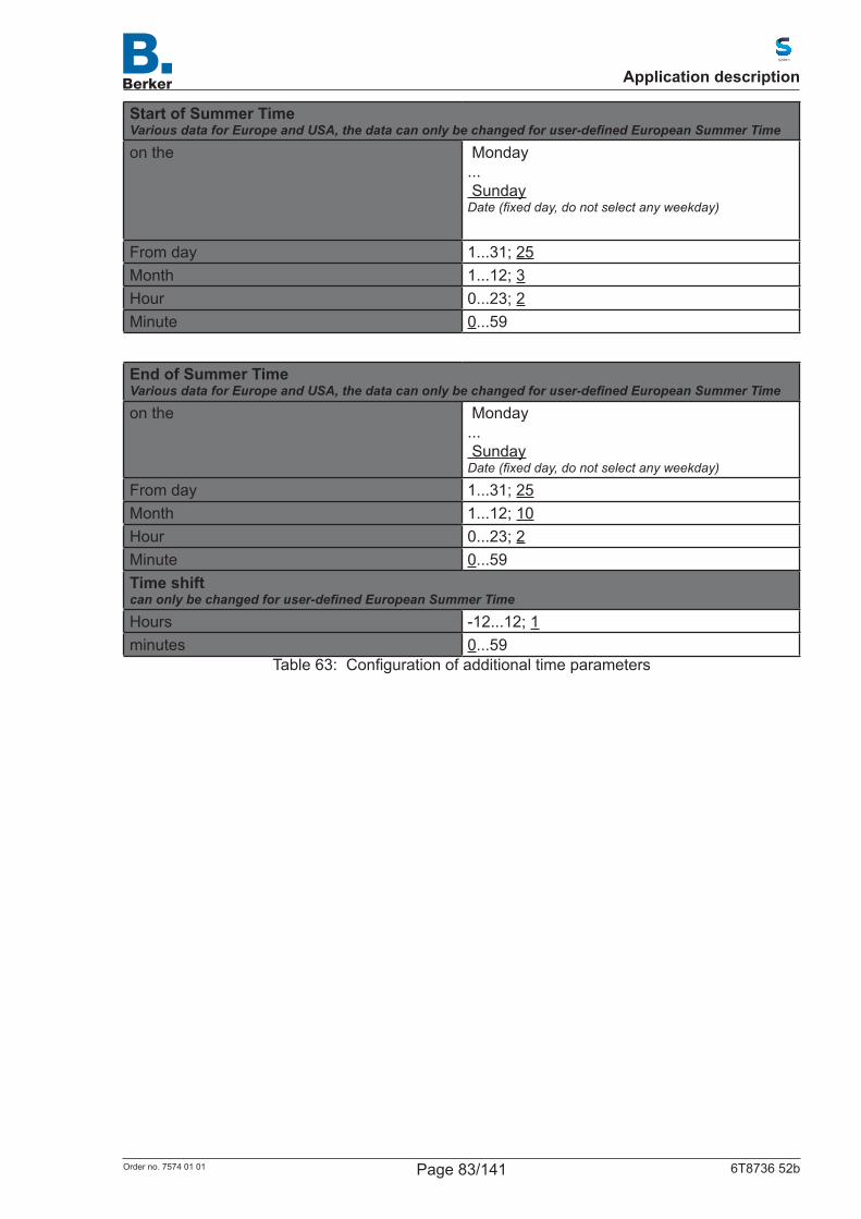
Start of Summer TimeVarious data for Europe and USA, the data can only be changed for user-defined European Summer Time
on the Monday... SundayDate (fixed day, do not select any weekday)
From day 1...31; 25Month 1...12; 3Hour 0...23; 2Minute 0...59
End of Summer TimeVarious data for Europe and USA, the data can only be changed for user-defined European Summer Time
on the Monday... SundayDate (fixed day, do not select any weekday)
From day 1...31; 25Month 1...12; 10Hour 0...23; 2Minute 0...59Time shiftcan only be changed for user-defined European Summer Time
Hours -12...12; 1minutes 0...59
Table 63: Configurationofadditionaltimeparameters
Application description
Page 83/141Order no. 7574 01 01 6T8736 52b
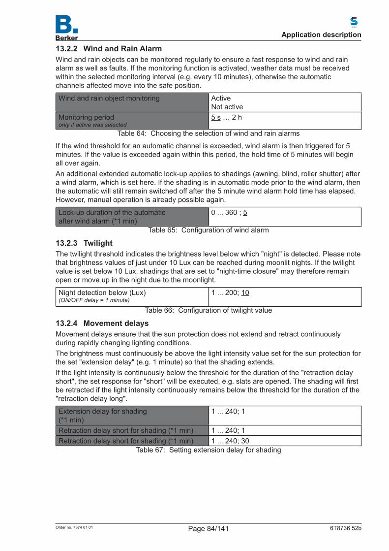
13.2.2 Wind and Rain AlarmWind and rain objects can be monitored regularly to ensure a fast response to wind and rain alarm as well as faults. If the monitoring function is activated, weather data must be received within the selected monitoring interval (e.g. every 10 minutes), otherwise the automatic channels affected move into the safe position.
Wind and rain object monitoring ActiveNot active
Monitoring periodonly if active was selected
5 s … 2 h
Table 64: Choosing the selection of wind and rain alarms
If the wind threshold for an automatic channel is exceeded, wind alarm is then triggered for 5 minutes. If the value is exceeded again within this period, the hold time of 5 minutes will begin all over again.An additional extended automatic lock-up applies to shadings (awning, blind, roller shutter) after a wind alarm, which is set here. If the shading is in automatic mode prior to the wind alarm, then the automatic will still remain switched off after the 5 minute wind alarm hold time has elapsed. However, manual operation is already possible again.
Lock-up duration of the automaticafter wind alarm (*1 min)
0 ... 360 ; 5
Table 65: Configurationofwindalarm
13.2.3 TwilightThe twilight threshold indicates the brightness level below which "night" is detected. Please note that brightness values of just under 10 Lux can be reached during moonlit nights. If the twilight value is set below 10 Lux, shadings that are set to "night-time closure" may therefore remain open or move up in the night due to the moonlight.
Night detection below (Lux)(ON/OFF delay = 1 minute)
1 ... 200; 10
Table 66: Configurationoftwilightvalue
13.2.4 Movement delaysMovement delays ensure that the sun protection does not extend and retract continuously during rapidly changing lighting conditions.The brightness must continuously be above the light intensity value set for the sun protection for the set "extension delay" (e.g. 1 minute) so that the shading extends.If the light intensity is continuously below the threshold for the duration of the "retraction delay short",thesetresponsefor"short"willbeexecuted,e.g.slatsareopened.Theshadingwillfirstbe retracted if the light intensity continuously remains below the threshold for the duration of the "retraction delay long".
Extension delay for shading(*1 min)
1 ... 240; 1
Retraction delay short for shading (*1 min) 1 ... 240; 1Retraction delay short for shading (*1 min) 1 ... 240; 30
Table 67: Setting extension delay for shading
Application description
Page 84/141Order no. 7574 01 01 6T8736 52b
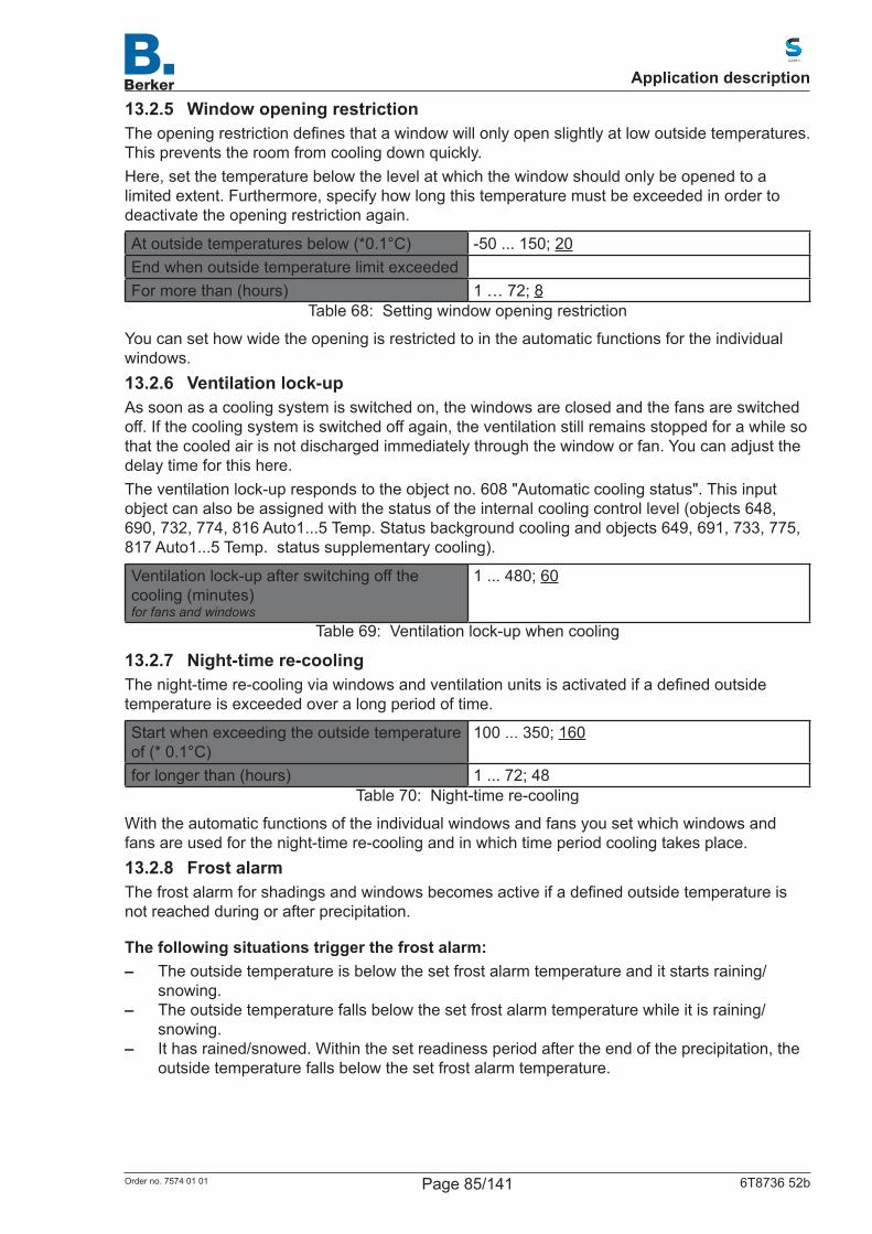
13.2.5 Window opening restrictionTheopeningrestrictiondefinesthatawindowwillonlyopenslightlyatlowoutsidetemperatures.Thispreventstheroomfromcoolingdownquickly.Here, set the temperature below the level at which the window should only be opened to a limited extent. Furthermore, specify how long this temperature must be exceeded in order to deactivate the opening restriction again.
At outside temperatures below (*0.1°C) -50 ... 150; 20End when outside temperature limit exceededFor more than (hours) 1 … 72; 8
Table 68: Setting window opening restriction
You can set how wide the opening is restricted to in the automatic functions for the individual windows.13.2.6 Ventilation lock-upAs soon as a cooling system is switched on, the windows are closed and the fans are switched off. If the cooling system is switched off again, the ventilation still remains stopped for a while so that the cooled air is not discharged immediately through the window or fan. You can adjust the delay time for this here.The ventilation lock-up responds to the object no. 608 "Automatic cooling status". This input object can also be assigned with the status of the internal cooling control level (objects 648, 690, 732, 774, 816 Auto1...5 Temp. Status background cooling and objects 649, 691, 733, 775, 817 Auto1...5 Temp. status supplementary cooling).
Ventilation lock-up after switching off the cooling (minutes)for fans and windows
1 ... 480; 60
Table 69: Ventilation lock-up when cooling
13.2.7 Night-time re-coolingThenight-timere-coolingviawindowsandventilationunitsisactivatedifadefinedoutsidetemperature is exceeded over a long period of time.
Start when exceeding the outside temperature of (* 0.1°C)
100 ... 350; 160
for longer than (hours) 1 ... 72; 48Table 70: Night-time re-cooling
With the automatic functions of the individual windows and fans you set which windows and fans are used for the night-time re-cooling and in which time period cooling takes place.13.2.8 Frost alarmThefrostalarmforshadingsandwindowsbecomesactiveifadefinedoutsidetemperatureisnot reached during or after precipitation.
The following situations trigger the frost alarm: – The outside temperature is below the set frost alarm temperature and it starts raining/
snowing. – The outside temperature falls below the set frost alarm temperature while it is raining/
snowing. – It has rained/snowed. Within the set readiness period after the end of the precipitation, the
outside temperature falls below the set frost alarm temperature.
Application description
Page 85/141Order no. 7574 01 01 6T8736 52b
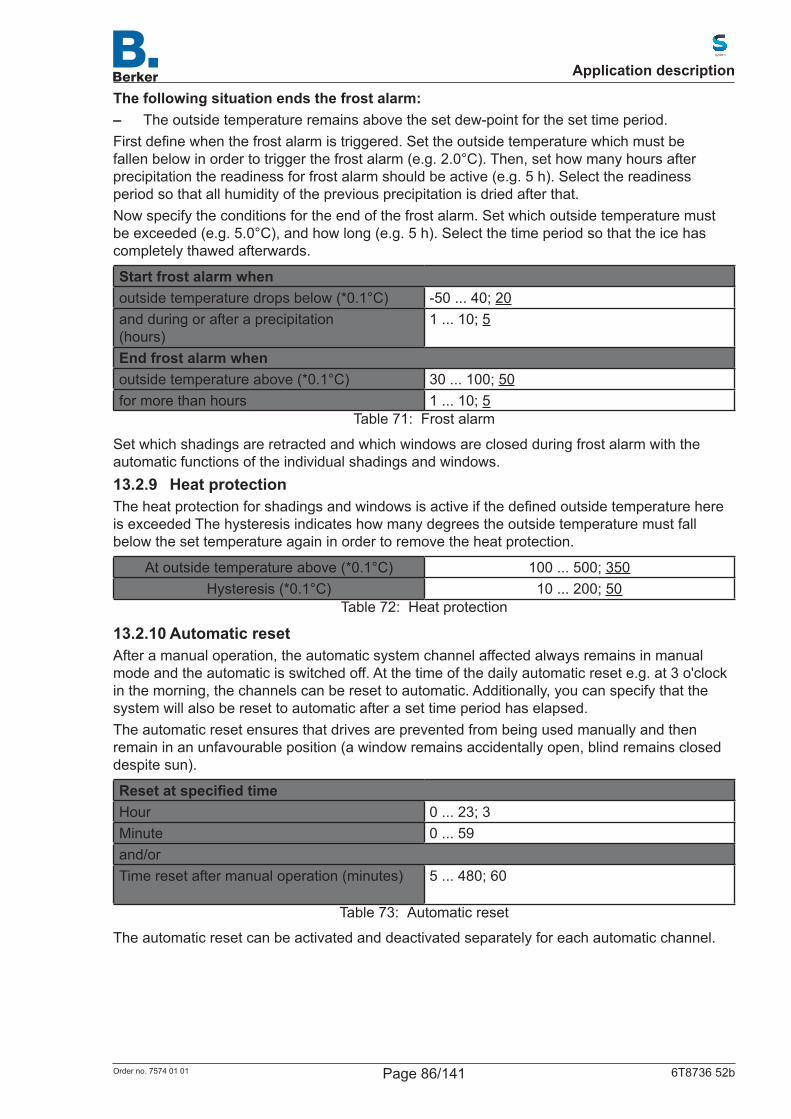
The following situation ends the frost alarm: – The outside temperature remains above the set dew-point for the set time period.Firstdefinewhenthefrostalarmistriggered.Settheoutsidetemperaturewhichmustbefallen below in order to trigger the frost alarm (e.g. 2.0°C). Then, set how many hours after precipitation the readiness for frost alarm should be active (e.g. 5 h). Select the readiness period so that all humidity of the previous precipitation is dried after that.Now specify the conditions for the end of the frost alarm. Set which outside temperature must be exceeded (e.g. 5.0°C), and how long (e.g. 5 h). Select the time period so that the ice has completely thawed afterwards.
Start frost alarm whenoutside temperature drops below (*0.1°C) -50 ... 40; 20and during or after a precipitation(hours)
1 ... 10; 5
End frost alarm whenoutside temperature above (*0.1°C) 30 ... 100; 50for more than hours 1 ... 10; 5
Table 71: Frost alarm
Set which shadings are retracted and which windows are closed during frost alarm with the automatic functions of the individual shadings and windows.13.2.9 Heat protectionTheheatprotectionforshadingsandwindowsisactiveifthedefinedoutsidetemperaturehereis exceeded The hysteresis indicates how many degrees the outside temperature must fall below the set temperature again in order to remove the heat protection.
At outside temperature above (*0.1°C) 100 ... 500; 350Hysteresis (*0.1°C) 10 ... 200; 50
Table 72: Heat protection
13.2.10 Automatic resetAfter a manual operation, the automatic system channel affected always remains in manual mode and the automatic is switched off. At the time of the daily automatic reset e.g. at 3 o'clock in the morning, the channels can be reset to automatic. Additionally, you can specify that the system will also be reset to automatic after a set time period has elapsed.The automatic reset ensures that drives are prevented from being used manually and then remain in an unfavourable position (a window remains accidentally open, blind remains closed despite sun).
ResetatspecifiedtimeHour 0 ... 23; 3Minute 0 ... 59and/orTime reset after manual operation (minutes) 5 ... 480; 60
Table 73: Automatic reset
The automatic reset can be activated and deactivated separately for each automatic channel.
Application description
Page 86/141Order no. 7574 01 01 6T8736 52b
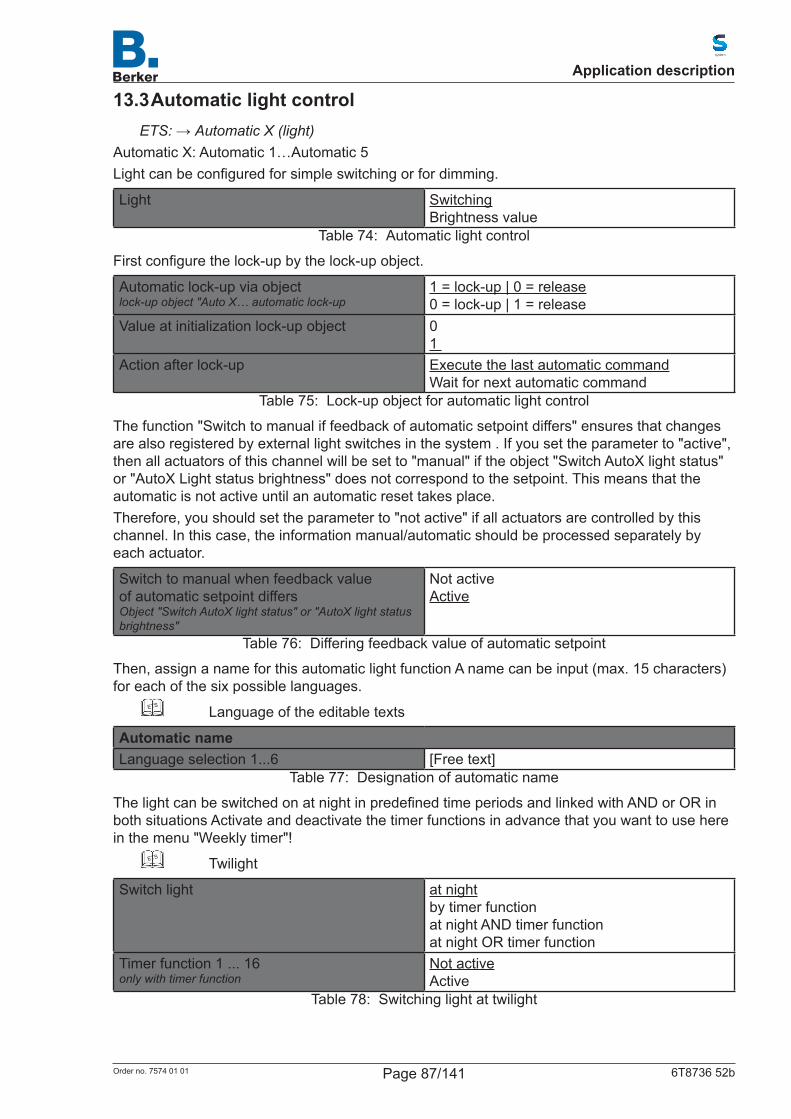
13.3 Automatic light controlETS: →Automatic X (light)
Automatic X: Automatic 1…Automatic 5Lightcanbeconfiguredforsimpleswitchingorfordimming.
Light SwitchingBrightness value
Table 74: Automatic light control
Firstconfigurethelock-upbythelock-upobject.
Automatic lock-up via objectlock-up object "Auto X… automatic lock-up
1 = lock-up | 0 = release0 = lock-up | 1 = release
Value at initialization lock-up object 01
Action after lock-up Execute the last automatic commandWait for next automatic command
Table 75: Lock-up object for automatic light control
The function "Switch to manual if feedback of automatic setpoint differs" ensures that changes are also registered by external light switches in the system . If you set the parameter to "active", then all actuators of this channel will be set to "manual" if the object "Switch AutoX light status" or "AutoX Light status brightness" does not correspond to the setpoint. This means that the automatic is not active until an automatic reset takes place. Therefore, you should set the parameter to "not active" if all actuators are controlled by this channel. In this case, the information manual/automatic should be processed separately by each actuator.
Switch to manual when feedback value of automatic setpoint differsObject "Switch AutoX light status" or "AutoX light status brightness"
Not activeActive
Table 76: Differing feedback value of automatic setpoint
Then, assign a name for this automatic light function A name can be input (max. 15 characters) for each of the six possible languages.
ETS Language of the editable texts
Automatic nameLanguage selection 1...6 [Free text]
Table 77: Designation of automatic name
ThelightcanbeswitchedonatnightinpredefinedtimeperiodsandlinkedwithANDorORinboth situations Activate and deactivate the timer functions in advance that you want to use here in the menu "Weekly timer"!
ETS Twilight
Switch light at nightby timer functionat night AND timer functionat night OR timer function
Timer function 1 ... 16only with timer function
Not activeActive
Table 78: Switching light at twilight
Application description
Page 87/141Order no. 7574 01 01 6T8736 52b
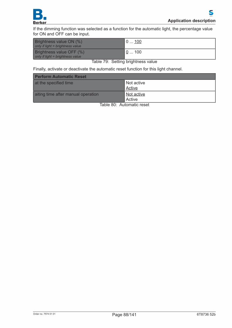
If the dimming function was selected as a function for the automatic light, the percentage value for ON and OFF can be input.
Brightness value ON (%)only if light = brightness value
0 ... 100
Brightness value OFF (%)only if light = brightness value
0 ... 100
Table 79: Setting brightness value
Finally, activate or deactivate the automatic reset function for this light channel.
Perform Automatic Resetatthespecifiedtime Not active
Activeaiting time after manual operation Not active
ActiveTable 80: Automatic reset
Application description
Page 88/141Order no. 7574 01 01 6T8736 52b
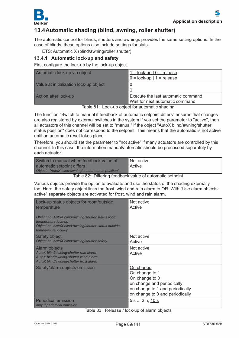
13.4 Automatic shading (blind, awning, roller shutter)The automatic control for blinds, shutters and awnings provides the same setting options. In the case of blinds, these options also include settings for slats.
ETS: Automatic X (blind/awning/roller shutter)13.4.1 Automatic lock-up and safetyFirstconfigurethelock-upbythelock-upobject.
Automatic lock-up via object 1 = lock-up | 0 = release0 = lock-up | 1 = release
Value at initialization lock-up object 01
Action after lock-up Execute the last automatic commandWait for next automatic command
Table 81: Lock-up object for automatic shading
The function "Switch to manual if feedback of automatic setpoint differs" ensures that changes are also registered by external switches in the system If you set the parameter to "active", then all actuators of this channel will be set to "manual" if the object "AutoX blind/awning/shutter status position" does not correspond to the setpoint. This means that the automatic is not active until an automatic reset takes place.Therefore, you should set the parameter to "not active" if many actuators are controlled by this channel. In this case, the information manual/automatic should be processed separately by each actuator.
Switch to manual when feedback value of automatic setpoint differsObjects "AutoX blind/awning/shutter status position"
Not activeActive
Table 82: Differing feedback value of automatic setpoint
Various objects provide the option to evaluate and use the status of the shading externally, too. Here, the safety object links the frost, wind and rain alarm to OR. With "Use alarm objects: active" separate objects are activated for frost, wind and rain alarm.
Lock-up status objects for room/outside temperature Object no. AutoX blind/awning/shutter status room temperature lock-upObject no. AutoX blind/awning/shutter status outside temperature lock-up
Not activeActive
Safety objectObject no. AutoX blind/awning/shutter safety
Not activeActive
Alarm objectsAutoX blind/awning/shutter rain alarmAutoX blind/awning/shutter wind alarmAutoX blind/awning/shutter frost alarm
Not activeActive
Safety/alarm objects emission On changeOn change to 1On change to 0on change and periodicallyon change to 1 and periodicallyon change to 0 and periodically
Periodical emissiononly if periodical emission
5 s ... 2 h; 10 s
Table 83: Release / lock-up of alarm objects
Application description
Page 89/141Order no. 7574 01 01 6T8736 52b
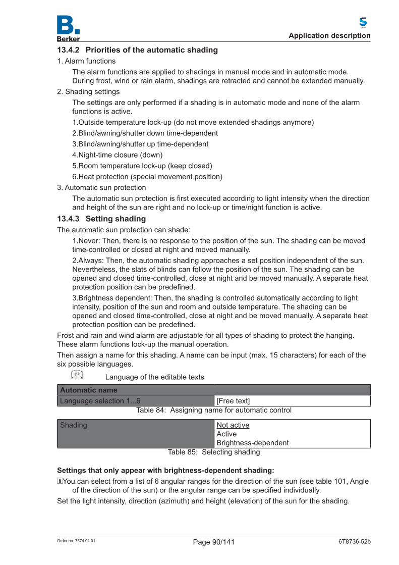
13.4.2 Priorities of the automatic shading1. Alarm functions
The alarm functions are applied to shadings in manual mode and in automatic mode. During frost, wind or rain alarm, shadings are retracted and cannot be extended manually.
2. Shading settingsThe settings are only performed if a shading is in automatic mode and none of the alarm functions is active.1.Outside temperature lock-up (do not move extended shadings anymore)2.Blind/awning/shutter down time-dependent3.Blind/awning/shutter up time-dependent4.Night-time closure (down)5.Room temperature lock-up (keep closed)6.Heat protection (special movement position)
3. Automatic sun protectionTheautomaticsunprotectionisfirstexecutedaccordingtolightintensitywhenthedirectionand height of the sun are right and no lock-up or time/night function is active.
13.4.3 Setting shadingThe automatic sun protection can shade:
1.Never: Then, there is no response to the position of the sun. The shading can be moved time-controlled or closed at night and moved manually.2.Always: Then, the automatic shading approaches a set position independent of the sun. Nevertheless, the slats of blinds can follow the position of the sun. The shading can be opened and closed time-controlled, close at night and be moved manually. A separate heat protectionpositioncanbepredefined.3.Brightness dependent: Then, the shading is controlled automatically according to light intensity, position of the sun and room and outside temperature. The shading can be opened and closed time-controlled, close at night and be moved manually. A separate heat protectionpositioncanbepredefined.
Frost and rain and wind alarm are adjustable for all types of shading to protect the hanging. These alarm functions lock-up the manual operation.Then assign a name for this shading. A name can be input (max. 15 characters) for each of the six possible languages.
ETS Language of the editable texts
Automatic nameLanguage selection 1...6 [Free text]
Table 84: Assigning name for automatic control
Shading Not activeActiveBrightness-dependent
Table 85: Selecting shading
Settings that only appear with brightness-dependent shading:You can select from a list of 6 angular ranges for the direction of the sun (see table 101, Angle
ofthedirectionofthesun)ortheangularrangecanbespecifiedindividually.Set the light intensity, direction (azimuth) and height (elevation) of the sun for the shading.
Application description
Page 90/141Order no. 7574 01 01 6T8736 52b
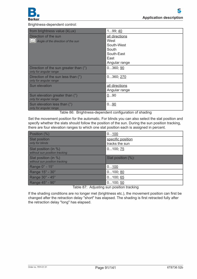
Brightness-dependent control:
from brightness value (kLux) 1...99; 40Direction of the sun
ETS Angle of the direction of the sunall directionsWestSouth-WestSouthSouth-EastEastAngular range
Direction of the sun greater than (°)only for angular range
0...360; 90
Direction of the sun less than (°)only for angular range
0...360; 270
Sun elevation all directionsAngular range
Sun elevation greater than (°)only for angular range
0...90
Sun elevation less than (°)only for angular range
0...90
Table 86: Brightness-dependentconfigurationofshading
Set the movement position for the automatic. For blinds you can also select the slat position and specify whether the slats should follow the position of the sun. During the sun position tracking, there are four elevation ranges to which one slat position each is assigned in percent.
Position (%) 0...100Slat positiononly for blinds
specificpositiontracks the sun
Slat position (in %)without sun position tracking
0...100; 75
Slat position (in %)without sun position tracking
Slat position (%):
Range 0° - 15° 0...100Range 15° - 30° 0...100; 80Range 30° - 45° 0...100; 65Range 45° - 90° 0...100; 50
Table 87: Adjusting sun position tracking
Iftheshadingconditionsarenolongermet(brightnessetc.),themovementpositioncanfirstbechangedaftertheretractiondelay"short"haselapsed.Theshadingisfirstretractedfullyafterthe retraction delay "long" has elapsed.
Application description
Page 91/141Order no. 7574 01 01 6T8736 52b
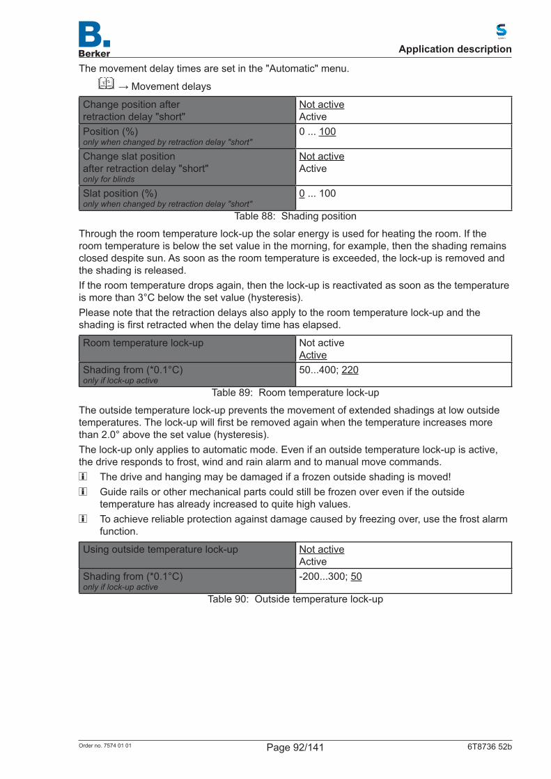
The movement delay times are set in the "Automatic" menu.ETS →Movementdelays
Change position afterretraction delay "short"
Not activeActive
Position (%)only when changed by retraction delay "short"
0 ... 100
Change slat positionafter retraction delay "short"only for blinds
Not activeActive
Slat position (%)only when changed by retraction delay "short"
0 ... 100
Table 88: Shading position
Through the room temperature lock-up the solar energy is used for heating the room. If the room temperature is below the set value in the morning, for example, then the shading remains closed despite sun. As soon as the room temperature is exceeded, the lock-up is removed and the shading is released.If the room temperature drops again, then the lock-up is reactivated as soon as the temperature is more than 3°C below the set value (hysteresis).Please note that the retraction delays also apply to the room temperature lock-up and the shadingisfirstretractedwhenthedelaytimehaselapsed.
Room temperature lock-up Not activeActive
Shading from (*0.1°C)only if lock-up active
50...400; 220
Table 89: Room temperature lock-up
The outside temperature lock-up prevents the movement of extended shadings at low outside temperatures.Thelock-upwillfirstberemovedagainwhenthetemperatureincreasesmorethan 2.0° above the set value (hysteresis).The lock-up only applies to automatic mode. Even if an outside temperature lock-up is active, the drive responds to frost, wind and rain alarm and to manual move commands.
The drive and hanging may be damaged if a frozen outside shading is moved! Guide rails or other mechanical parts could still be frozen over even if the outside
temperaturehasalreadyincreasedtoquitehighvalues. To achieve reliable protection against damage caused by freezing over, use the frost alarm
function.
Using outside temperature lock-up Not activeActive
Shading from (*0.1°C)only if lock-up active
-200...300; 50
Table 90: Outside temperature lock-up
Application description
Page 92/141Order no. 7574 01 01 6T8736 52b
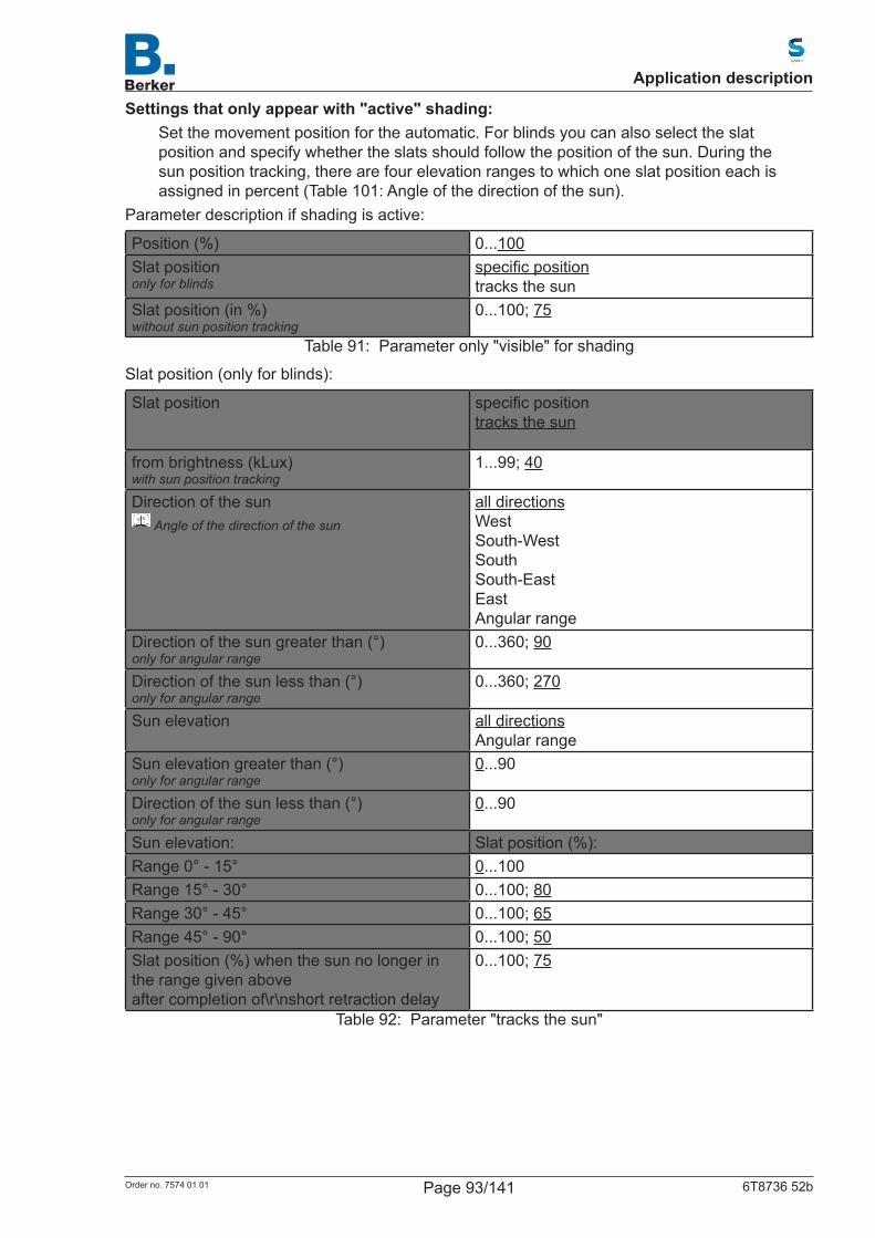
Settings that only appear with "active" shading:Set the movement position for the automatic. For blinds you can also select the slat position and specify whether the slats should follow the position of the sun. During the sun position tracking, there are four elevation ranges to which one slat position each is assigned in percent (Table 101: Angle of the direction of the sun).
Parameter description if shading is active:
Position (%) 0...100Slat positiononly for blinds
specificpositiontracks the sun
Slat position (in %)without sun position tracking
0...100; 75
Table 91: Parameter only "visible" for shading
Slat position (only for blinds):
Slat position specificpositiontracks the sun
from brightness (kLux)with sun position tracking
1...99; 40
Direction of the sunETS
Angle of the direction of the sun
all directionsWestSouth-WestSouthSouth-EastEastAngular range
Direction of the sun greater than (°)only for angular range
0...360; 90
Direction of the sun less than (°)only for angular range
0...360; 270
Sun elevation all directionsAngular range
Sun elevation greater than (°)only for angular range
0...90
Direction of the sun less than (°)only for angular range
0...90
Sun elevation: Slat position (%):Range 0° - 15° 0...100Range 15° - 30° 0...100; 80Range 30° - 45° 0...100; 65Range 45° - 90° 0...100; 50Slat position (%) when the sun no longer in the range given aboveafter completion of\r\nshort retraction delay
0...100; 75
Table 92: Parameter "tracks the sun"
Application description
Page 93/141Order no. 7574 01 01 6T8736 52b
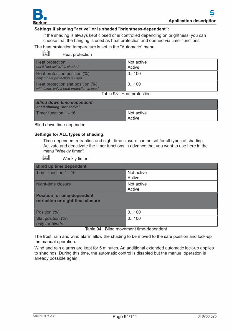
Settings if shading "active" or is shaded "brightness-dependent":If the shading is always kept closed or is controlled depending on brightness, you can choose that the hanging is used as heat protection and opened via timer functions.
The heat protection temperature is set in the "Automatic" menu.ETS Heat protection
Heat protectionnot if "not active" is shaded
Not activeActive
Heat protection position (%)only if heat protection is used
0...100
Heat protection slat position (%)with blind, only if heat protection is used
0...100
Table 93: Heat protection
Blind down time dependent not if shading "not active"
Timer function 1 - 16 Not activeActive
Blind down time-dependent
Settings for ALL types of shading:Time-dependent retraction and night-time closure can be set for all types of shading. Activate and deactivate the timer functions in advance that you want to use here in the menu "Weekly timer"!
ETS Weekly timer
Blind up time dependentTimer function 1 - 16 Not active
ActiveNight-time closure Not active
ActivePosition for time-dependent retraction or night-time closure Position (%) 0...100Slat position (%)only for blinds
0...100
Table 94: Blind movement time-dependent
The frost, rain and wind alarm allow the shading to be moved to the safe position and lock-up the manual operation.Wind and rain alarms are kept for 5 minutes. An additional extended automatic lock-up applies to shadings. During this time, the automatic control is disabled but the manual operation is already possible again.
Application description
Page 94/141Order no. 7574 01 01 6T8736 52b
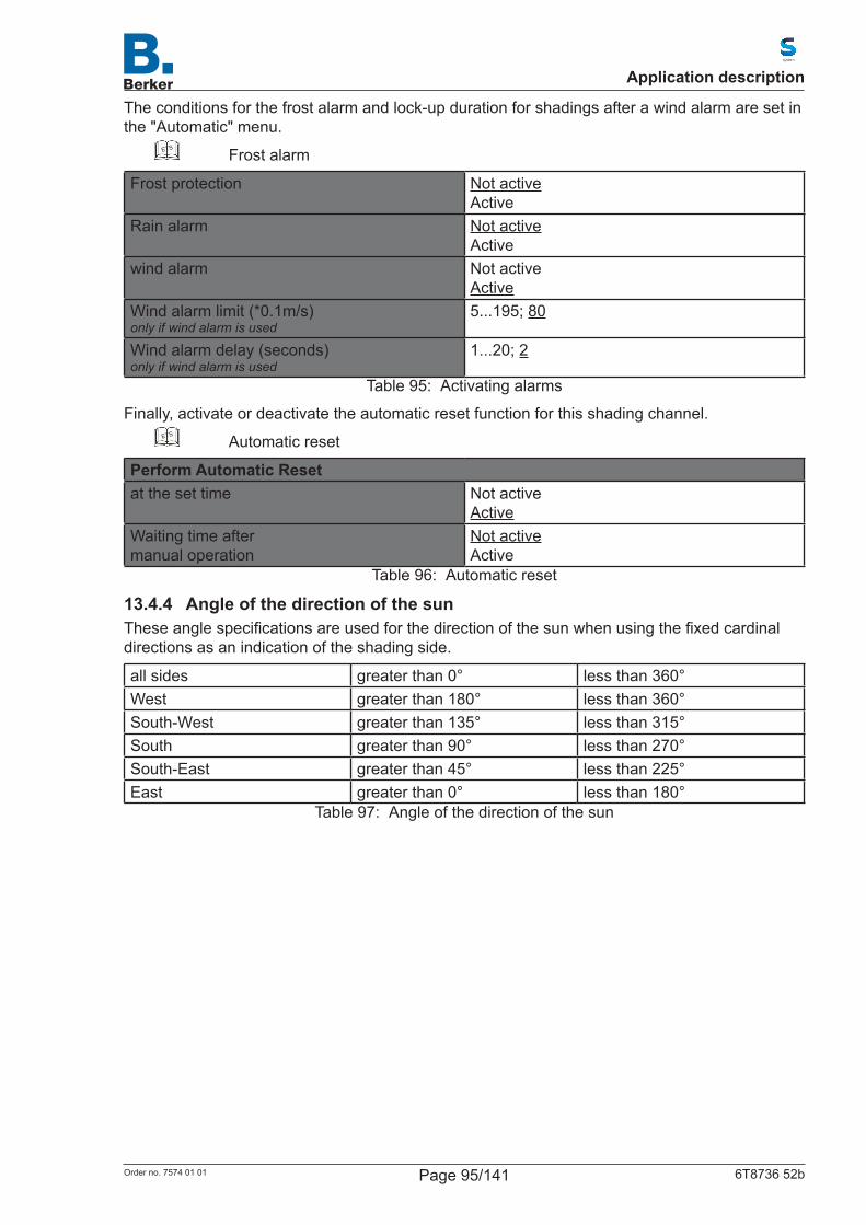
The conditions for the frost alarm and lock-up duration for shadings after a wind alarm are set in the "Automatic" menu.
ETS Frost alarm
Frost protection Not activeActive
Rain alarm Not activeActive
wind alarm Not activeActive
Wind alarm limit (*0.1m/s)only if wind alarm is used
5...195; 80
Wind alarm delay (seconds)only if wind alarm is used
1...20; 2
Table 95: Activating alarms
Finally, activate or deactivate the automatic reset function for this shading channel.ETS Automatic reset
Perform Automatic Resetat the set time Not active
ActiveWaiting time after manual operation
Not activeActive
Table 96: Automatic reset
13.4.4 Angle of the direction of the sunTheseanglespecificationsareusedforthedirectionofthesunwhenusingthefixedcardinaldirections as an indication of the shading side.
all sides greater than 0° less than 360°West greater than 180° less than 360°South-West greater than 135° less than 315°South greater than 90° less than 270°South-East greater than 45° less than 225°East greater than 0° less than 180°
Table 97: Angle of the direction of the sun
Application description
Page 95/141Order no. 7574 01 01 6T8736 52b
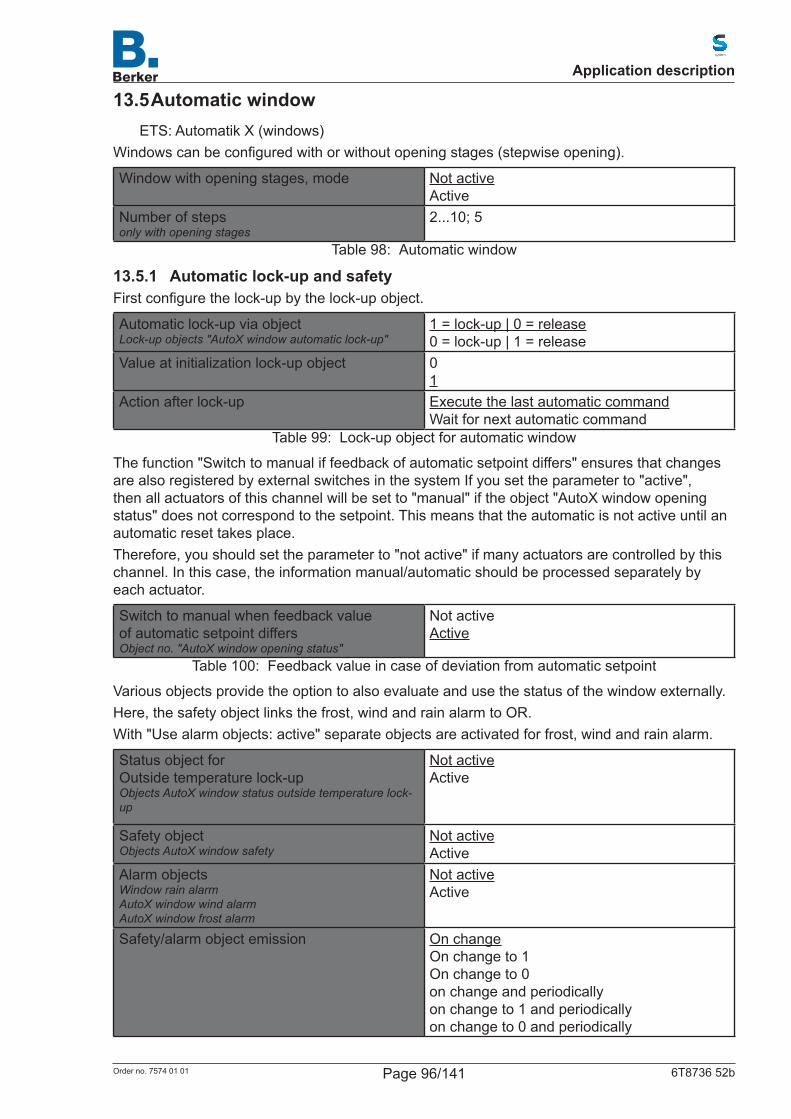
13.5 Automatic windowETS: Automatik X (windows)
Windowscanbeconfiguredwithorwithoutopeningstages(stepwiseopening).
Window with opening stages, mode Not activeActive
Number of stepsonly with opening stages
2...10; 5
Table 98: Automatic window
13.5.1 Automatic lock-up and safetyFirstconfigurethelock-upbythelock-upobject.
Automatic lock-up via objectLock-up objects "AutoX window automatic lock-up"
1 = lock-up | 0 = release0 = lock-up | 1 = release
Value at initialization lock-up object 01
Action after lock-up Execute the last automatic commandWait for next automatic command
Table 99: Lock-up object for automatic window
The function "Switch to manual if feedback of automatic setpoint differs" ensures that changes are also registered by external switches in the system If you set the parameter to "active", then all actuators of this channel will be set to "manual" if the object "AutoX window opening status" does not correspond to the setpoint. This means that the automatic is not active until an automatic reset takes place.Therefore, you should set the parameter to "not active" if many actuators are controlled by this channel. In this case, the information manual/automatic should be processed separately by each actuator.
Switch to manual when feedback value of automatic setpoint differsObject no. "AutoX window opening status"
Not activeActive
Table 100: Feedback value in case of deviation from automatic setpoint
Various objects provide the option to also evaluate and use the status of the window externally.Here, the safety object links the frost, wind and rain alarm to OR.With "Use alarm objects: active" separate objects are activated for frost, wind and rain alarm.
Status object forOutside temperature lock-upObjects AutoX window status outside temperature lock-up
Not activeActive
Safety objectObjects AutoX window safety
Not activeActive
Alarm objectsWindow rain alarmAutoX window wind alarmAutoX window frost alarm
Not activeActive
Safety/alarm object emission On changeOn change to 1On change to 0on change and periodicallyon change to 1 and periodicallyon change to 0 and periodically
Application description
Page 96/141Order no. 7574 01 01 6T8736 52b

Periodical emissiononly if periodical emission
5 s ... 2 h; 10 s
Table 101: Einstellungen für die Alarm-ObjekteSettings for alarm objects
13.5.2 Priorities of the automatic window1. Alarm functions
The alarm functions are applied to windows in manual mode and in automatic mode. During frost, wind or rain alarm, windows are closed and cannot be opened manually.The ventilation lock-up also closes windows (object no. 608 "Automatic cooling status" =1). They are then in automatic mode and can then be immediately reopened manually. The delay time for the ventilation lock-up can be adjusted.
2. Ventilation settingsThe settings are only performed if a window is in automatic mode and none of the alarm functions are active.The priorities must be observed in the following order:1. Time-dependent closure2. Outside temperature lock-up (keep closed)3. Time-dependent ventilation (open)4. Supply air temperature lock-up (keep closed)5. Lowest priority: Night-time re-cooling (open)This means that timed ventilation or night-time re-cooling, for example, only take place if the outside temperature is above the set value of the outside temperature lock-up.
3. Automatic ventilationThe automatic ventilation according to temperature, humidity or CO2 content is only executed if no lock-up is active.
Application description
Page 97/141Order no. 7574 01 01 6T8736 52b

13.5.3 Setting window ventilationRoom temperature, relative humidity and CO2-content of the indoor air can be evaluated for the ventilation.Then, assign a name for this window. A name can be input (max. 15 characters) for each of the six possible languages.
ETS Language of the editable texts
Automatic nameLanguage selection 1...6 [Free text]
Table 102: Language selection of automatic name
Evaluation room temperature Not activeActive
Window open from temp. (*0.1 °C)(Hysteresis = 2°C)only for ventilation according to room temperature
50...400; 220
Evaluation humidity Not activeActive
Window open from humidity (% r.h)(Hysteresis = 3%)only for ventilation according to room temperature
10...95; 60
Evaluation of CO2 Not activeActive
Window open from CO2 value (*10 ppm)only for ventilation according to CO2 value
50...200; 80
Window closed from CO2 value (*10 ppm)only for ventilation according to CO2 value
50...200; 55
Table 103: Setting ventilation parameters
Application description
Page 98/141Order no. 7574 01 01 6T8736 52b
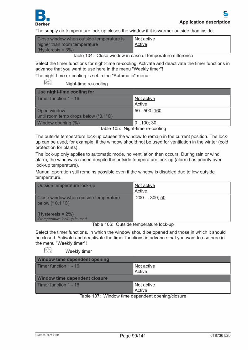
The supply air temperature lock-up closes the window if it is warmer outside than inside.
Close window when outside temperature is higher than room temperature(Hysteresis = 3%)
Not activeActive
Table 104: Close window in case of temperature difference
Select the timer functions for night-time re-cooling. Activate and deactivate the timer functions in advance that you want to use here in the menu "Weekly timer"!The night-time re-cooling is set in the "Automatic" menu.
ETS Night-time re-cooling
Use night-time cooling forTimer function 1 - 16 Not active
ActiveOpen windowuntil room temp drops below (*0.1°C)
50...500; 160
Window opening (%) 0...100; 30Table 105: Night-time re-cooling
The outside temperature lock-up causes the window to remain in the current position. The lock-up can be used, for example, if the window should not be used for ventilation in the winter (cold protection for plants).The lock-up only applies to automatic mode, no ventilation then occurs. During rain or wind alarm, the window is closed despite the outside temperature lock-up (alarm has priority over lock-up temperature).Manual operation still remains possible even if the window is disabled due to low outside temperature.
Outside temperature lock-up Not activeActive
Close window when outside temperature below (* 0.1 °C) (Hysteresis = 2%)if temperature lock-up is used
-200 ... 300; 50
Table 106: Outside temperature lock-up
Select the timer functions, in which the window should be opened and those in which it should be closed. Activate and deactivate the timer functions in advance that you want to use here in the menu "Weekly timer"!
ETS Weekly timer
Window time dependent openingTimer function 1 - 16 Not active
ActiveWindow time dependent closureTimer function 1 - 16 Not active
ActiveTable 107: Window time dependent opening/closure
Application description
Page 99/141Order no. 7574 01 01 6T8736 52b

The opening restriction restricts the opening range of the window at low outside temperatures. The opening restriction is set in the "Automatic" menu.
ETS Window opening restriction
Opening restriction at low outside temperatures
Not activeActive
Window opening (%)only for restricted openings
0 ... 100; 20
Table 108: Setting opening restriction
The ventilation lock-up is activated when switching on a cooling unit (object no. 608 "Automatic cooling status" =1) and closes the window. It can, however, be immediately reopened manually.Frost, rain and wind alarm, on the other hand, close the window and lock-up the manual operation. During rain alarm, the window can remain slightly open. Wind and rain alarms are kept for 5 minutes.The conditions for the frost alarm and delay time for the ventilation lock-up are set in the "Automatic" menu.
ETS Ventilation lock-up and frost alarm
Ventilation lock-up Not activeActive
Frost protection Not activeActive
Rain alarm Not activeActive
Gap opening during rainonly if rain alarm is used
Not activeActive
Window opening (%)only if gap opening is used
0 ... 100; 5
wind alarm Not activeActive
Wind alarm limit (*0.1m/s)only if wind alarm is used
5...195; 80
Wind alarm delay (seconds)only if wind alarm is used
1...20; 2
Table 109: Configurationofparameter"alarms"
Finally, activate or deactivate the automatic reset function for this window channel.ETS Automatic reset
Perform automatic resetatthespecifiedtime Not active
Activeaiting time after manual operation Not active
ActiveTable 110: Perform Automatic Reset
Application description
Page 100/141Order no. 7574 01 01 6T8736 52b
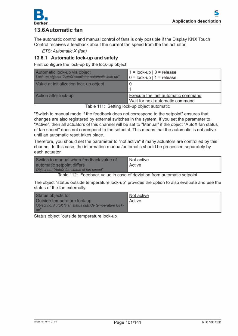
13.6 Automatic fanThe automatic control and manual control of fans is only possible if the Display KNX Touch Control receives a feedback about the current fan speed from the fan actuator.
ETS: Automatic X (fan)13.6.1 Automatic lock-up and safetyFirstconfigurethelock-upbythelock-upobject.
Automatic lock-up via objectLock-up objects "AutoX ventilator automatic lock-up"
1 = lock-up | 0 = release0 = lock-up | 1 = release
Value at initialization lock-up object 01
Action after lock-up Execute the last automatic commandWait for next automatic command
Table 111: Setting lock-up object automatic
"Switch to manual mode if the feedback does not correspond to the setpoint" ensures that changes are also registered by external switches in the system. If you set the parameter to "Active", then all actuators of this channel will be set to "Manual" if the object "AutoX fan status of fan speed" does not correspond to the setpoint. This means that the automatic is not active until an automatic reset takes place.Therefore, you should set the parameter to "not active" if many actuators are controlled by this channel. In this case, the information manual/automatic should be processed separately by each actuator.
Switch to manual when feedback value of automatic setpoint differsObject no. "AutoX fan status of fan speed"
Not activeActive
Table 112: Feedback value in case of deviation from automatic setpoint
The object "status outside temperature lock-up" provides the option to also evaluate and use the status of the fan externally.
Status objects forOutside temperature lock-upObject no. AutoX "Fan status outside temperature lock-up"
Not activeActive
Status object "outside temperature lock-up
Application description
Page 101/141Order no. 7574 01 01 6T8736 52b
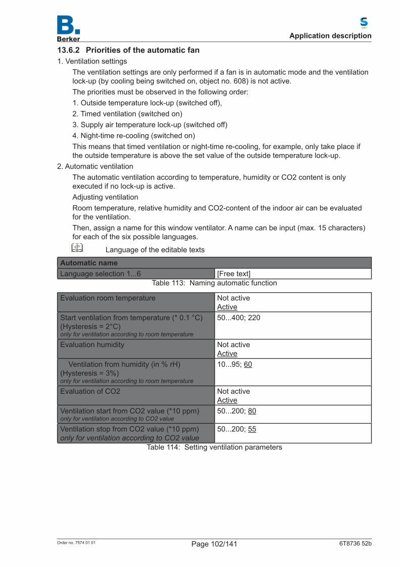
13.6.2 Priorities of the automatic fan1. Ventilation settings
The ventilation settings are only performed if a fan is in automatic mode and the ventilation lock-up (by cooling being switched on, object no. 608) is not active.The priorities must be observed in the following order:1. Outside temperature lock-up (switched off),2. Timed ventilation (switched on)3. Supply air temperature lock-up (switched off)4. Night-time re-cooling (switched on)This means that timed ventilation or night-time re-cooling, for example, only take place if the outside temperature is above the set value of the outside temperature lock-up.
2. Automatic ventilationThe automatic ventilation according to temperature, humidity or CO2 content is only executed if no lock-up is active.Adjusting ventilationRoom temperature, relative humidity and CO2-content of the indoor air can be evaluated for the ventilation.Then, assign a name for this window ventilator. A name can be input (max. 15 characters) for each of the six possible languages.
ETS Language of the editable texts
Automatic nameLanguage selection 1...6 [Free text]
Table 113: Naming automatic function
Evaluation room temperature Not active Active
Start ventilation from temperature (* 0.1 °C)(Hysteresis = 2°C)only for ventilation according to room temperature
50...400; 220
Evaluation humidity Not activeActive
Ventilation from humidity (in % rH)(Hysteresis = 3%)only for ventilation according to room temperature
10...95; 60
Evaluation of CO2 Not activeActive
Ventilation start from CO2 value (*10 ppm)only for ventilation according to CO2 value
50...200; 80
Ventilation stop from CO2 value (*10 ppm)only for ventilation according to CO2 value
50...200; 55
Table 114: Setting ventilation parameters
Application description
Page 102/141Order no. 7574 01 01 6T8736 52b
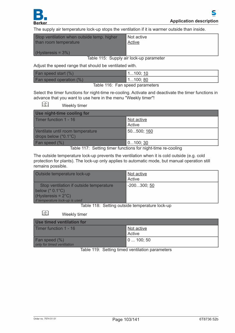
The supply air temperature lock-up stops the ventilation if it is warmer outside than inside.
Stop ventilation when outside temp. higher than room temperature (Hysteresis = 3%)
Not activeActive
Table 115: Supply air lock-up parameter
Adjust the speed range that should be ventilated with.
Fan speed start (%) 1...100; 10Fan speed operation (%) 1...100; 80
Table 116: Fan speed parameters
Select the timer functions for night-time re-cooling. Activate and deactivate the timer functions in advance that you want to use here in the menu "Weekly timer"!
ETS Weekly timer
Use night-time cooling forTimer function 1 - 16 Not active
ActiveVentilate until room temperaturedrops below (*0.1°C)
50...500; 160
Fan speed (%) 0...100; 30Table 117: Setting timer functions for night-time re-cooling
The outside temperature lock-up prevents the ventilation when it is cold outside (e.g. cold protection for plants). The lock-up only applies to automatic mode, but manual operation still remains possible.
Outside temperature lock-up Not activeActive
Stop ventilation if outside temperature below (* 0.1°C)(Hysteresis = 2°C)if temperature lock-up is used
-200...300; 50
Table 118: Setting outside temperature lock-upETS Weekly timer
Use timed ventilation forTimer function 1 - 16 Not active
ActiveFan speed (%)only for timed ventilation
0 ... 100; 50
Table 119: Setting timed ventilation parameters
Application description
Page 103/141Order no. 7574 01 01 6T8736 52b
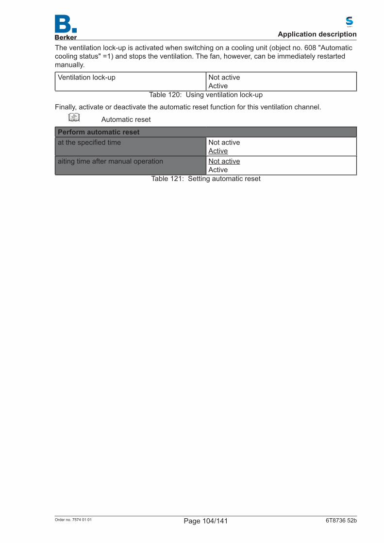
The ventilation lock-up is activated when switching on a cooling unit (object no. 608 "Automatic cooling status" =1) and stops the ventilation. The fan, however, can be immediately restarted manually.
Ventilation lock-up Not activeActive
Table 120: Using ventilation lock-up
Finally, activate or deactivate the automatic reset function for this ventilation channel.ETS Automatic reset
Perform automatic resetatthespecifiedtime Not active
Activeaiting time after manual operation Not active
ActiveTable 121: Setting automatic reset
Application description
Page 104/141Order no. 7574 01 01 6T8736 52b
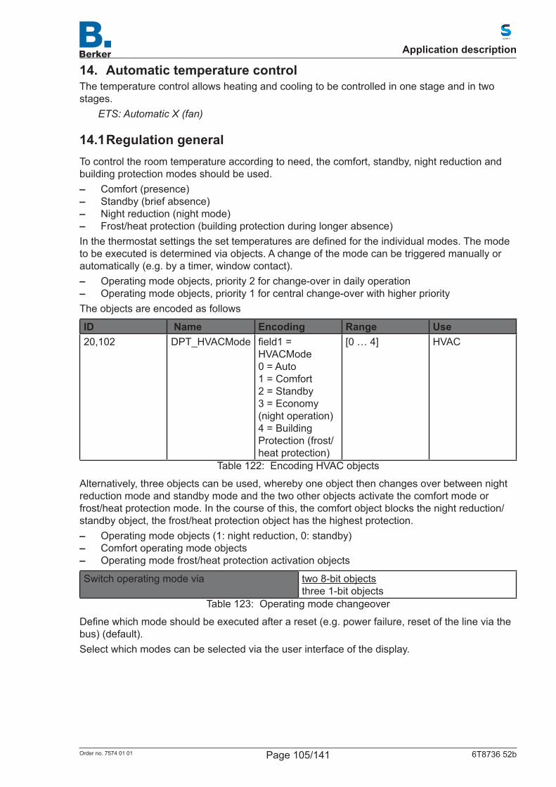
14. Automatic temperature controlThe temperature control allows heating and cooling to be controlled in one stage and in two stages.
ETS: Automatic X (fan)
14.1 Regulation generalTo control the room temperature according to need, the comfort, standby, night reduction and building protection modes should be used. – Comfort (presence) – Standby (brief absence) – Night reduction (night mode) – Frost/heat protection (building protection during longer absence)Inthethermostatsettingsthesettemperaturesaredefinedfortheindividualmodes.Themodeto be executed is determined via objects. A change of the mode can be triggered manually or automatically (e.g. by a timer, window contact). – Operating mode objects, priority 2 for change-over in daily operation – Operating mode objects, priority 1 for central change-over with higher priority
The objects are encoded as follows
ID Name Encoding Range Use20,102 DPT_HVACMode field1=
HVACMode0 = Auto1 = Comfort2 = Standby3 = Economy (night operation)4 = Building Protection (frost/heat protection)
[0 … 4] HVAC
Table 122: Encoding HVAC objects
Alternatively, three objects can be used, whereby one object then changes over between night reduction mode and standby mode and the two other objects activate the comfort mode or frost/heat protection mode. In the course of this, the comfort object blocks the night reduction/standby object, the frost/heat protection object has the highest protection. – Operating mode objects (1: night reduction, 0: standby) – Comfort operating mode objects – Operating mode frost/heat protection activation objects
Switch operating mode via two 8-bit objectsthree 1-bit objects
Table 123: Operating mode changeover
Definewhichmodeshouldbeexecutedafterareset(e.g.powerfailure,resetofthelineviathebus) (default).Select which modes can be selected via the user interface of the display.
Application description
Page 105/141Order no. 7574 01 01 6T8736 52b
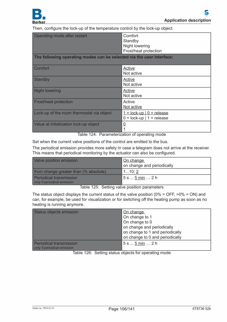
Then,configurethelock-upofthetemperaturecontrolbythelock-upobject.
Operating mode after restart ComfortStandbyNight loweringFrost/heat protection
The following operating modes can be selected via the user interface: Comfort Active
Not activeStandby Active
Not activeNight lowering Active
Not activeFrost/heat protection Active
Not activeLock-up of the room thermostat via object 1 = lock-up | 0 = release
0 = lock-up | 1 = releaseValue at initialization lock-up object 0
1Table 124: Parameterization of operating mode
Set when the current valve positions of the control are emitted to the bus.The periodical emission provides more safety in case a telegram does not arrive at the receiver. Thismeansthatperiodicalmonitoringbytheactuatorcanalsobeconfigured.
Valve position emission On change on change and periodically
from change greater than (% absolute) 1...10; 2Periodical transmissiononly if periodical emission
5 s ... 5 min … 2 h
Table 125: Setting valve position parameters
The status object displays the current status of the valve position (0% = OFF, >0% = ON) and can, for example, be used for visualization or for switching off the heating pump as soon as no heating is running anymore.
Status objects emission On change On change to 1On change to 0on change and periodicallyon change to 1 and periodicallyon change to 0 and periodically
Periodical transmissiononly if periodical emission
5 s ... 5 min … 2 h
Table 126: Setting status objects for operating mode
Application description
Page 106/141Order no. 7574 01 01 6T8736 52b
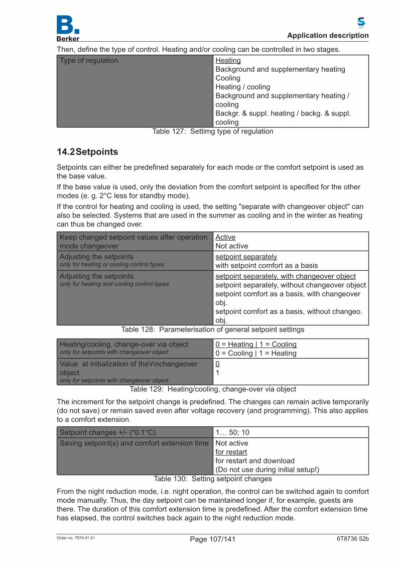
Then,definethetypeofcontrol.Heatingand/orcoolingcanbecontrolledintwostages.Type of regulation Heating
Background and supplementary heatingCoolingHeating / coolingBackground and supplementary heating / coolingBackgr. & suppl. heating / backg. & suppl. cooling
Table 127: Settimg type of regulation
14.2 SetpointsSetpointscaneitherbepredefinedseparatelyforeachmodeorthecomfortsetpointisusedasthe base value.Ifthebasevalueisused,onlythedeviationfromthecomfortsetpointisspecifiedfortheothermodes (e. g. 2°C less for standby mode).If the control for heating and cooling is used, the setting "separate with changeover object" can also be selected. Systems that are used in the summer as cooling and in the winter as heating can thus be changed over.
Keep changed setpoint values after operation mode changeover
ActiveNot active
Adjusting the setpointsonly for heating or cooling control types
setpoint separatelywith setpoint comfort as a basis
Adjusting the setpointsonly for heating and cooling control types
setpoint separately, with changeover objectsetpoint separately, without changeover objectsetpoint comfort as a basis, with changeover obj.setpoint comfort as a basis, without changeo. obj.
Table 128: Parameterisation of general setpoint settings
Heating/cooling, change-over via objectonly for setpoints with changeover object
0 = Heating | 1 = Cooling0 = Cooling | 1 = Heating
Value at initialization of the\r\nchangeover objectonly for setpoints with changeover object
01
Table 129: Heating/cooling, change-over via object
Theincrementforthesetpointchangeispredefined.Thechangescanremainactivetemporarily(do not save) or remain saved even after voltage recovery (and programming). This also applies to a comfort extension.
Setpoint changes +/- (*0.1°C) 1… 50; 10Saving setpoint(s) and comfort extension time
Not activefor restartfor restart and download(Do not use during initial setup!)
Table 130: Setting setpoint changes
From the night reduction mode, i.e. night operation, the control can be switched again to comfort mode manually. Thus, the day setpoint can be maintained longer if, for example, guests are there.Thedurationofthiscomfortextensiontimeispredefined.Afterthecomfortextensiontimehas elapsed, the control switches back again to the night reduction mode.
Application description
Page 107/141Order no. 7574 01 01 6T8736 52b
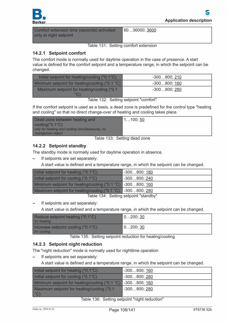
Comfort extension time (seconds) activated only at night setpoint
60…36000; 3600
Table 131: Setting comfort extension
14.2.1 Setpoint comfortThe comfort mode is normally used for daytime operation in the case of presence. A start valueisdefinedforthecomfortsetpointandatemperaturerange,inwhichthesetpointcanbechanged.
Initial setpoint for heating/cooling (*0.1°C) -300…800; 210Minimum setpoint for heating/cooling (*0.1 °C) -300…800; 160
Maximum setpoint for heating/cooling (*0.1 °C)
-300…800; 280
Table 132: Setting setpoint "comfort"
Ifthecomfortsetpointisusedasabasis,adeadzoneispredefinedforthecontroltype"heatingand cooling" so that no direct change-over of heating and cooling takes place.
Dead zone between heating and cooling(*0.1°C)only for heating and cooling simultaneously, no changeover object
1…100; 50
Table 133: Setting dead zone
14.2.2 Setpoint standbyThe standby mode is normally used for daytime operation in absence. – If setpoints are set separately:
Astartvalueisdefinedandatemperaturerange,inwhichthesetpointcanbechanged.
Initial setpoint for heating (*0.1°C) -300…800; 180Initial setpoint for cooling (*0.1°C) -300…800; 240Minimum setpoint for heating/cooling (*0.1 °C) -300…800; 160Maximum setpoint for heating/cooling (*0.1 °C) -300…800; 280
Table 134: Setting setpoint "standby"
– If setpoints are set separately:Astartvalueisdefinedandatemperaturerange,inwhichthesetpointcanbechanged.
Reduce setpoint heating (*0.1°C)for heating
0…200; 30
Increase setpoint cooling (*0.1°C)for cooling
0…200; 30
Table 135: Setting setpoint reduction for heating/cooling
14.2.3 Setpoint night reductionThe "night reduction" mode is normally used for nighttime operation. – If setpoints are set separately:
Astartvalueisdefinedandatemperaturerange,inwhichthesetpointcanbechanged.
Initial setpoint for heating (*0.1°C) -300…800; 160Initial setpoint for cooling (*0.1°C) -300…800; 280Minimum setpoint for heating/cooling (*0.1 °C) -300…800; 160Maximum setpoint for heating/cooling (*0.1 °C)
-300…800; 280
Table 136: Setting setpoint "night reduction"
Application description
Page 108/141Order no. 7574 01 01 6T8736 52b
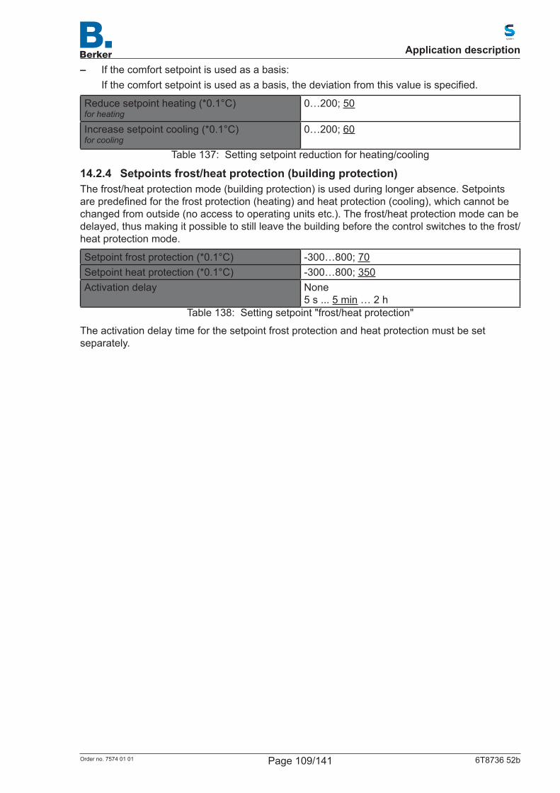
– If the comfort setpoint is used as a basis:Ifthecomfortsetpointisusedasabasis,thedeviationfromthisvalueisspecified.
Reduce setpoint heating (*0.1°C)for heating
0…200; 50
Increase setpoint cooling (*0.1°C)for cooling
0…200; 60
Table 137: Setting setpoint reduction for heating/cooling
14.2.4 Setpoints frost/heat protection (building protection)The frost/heat protection mode (building protection) is used during longer absence. Setpoints arepredefinedforthefrostprotection(heating)andheatprotection(cooling),whichcannotbechanged from outside (no access to operating units etc.). The frost/heat protection mode can be delayed, thus making it possible to still leave the building before the control switches to the frost/heat protection mode.
Setpoint frost protection (*0.1°C) -300…800; 70Setpoint heat protection (*0.1°C) -300…800; 350Activation delay None
5 s ... 5 min … 2 hTable 138: Setting setpoint "frost/heat protection"
The activation delay time for the setpoint frost protection and heat protection must be set separately.
Application description
Page 109/141Order no. 7574 01 01 6T8736 52b
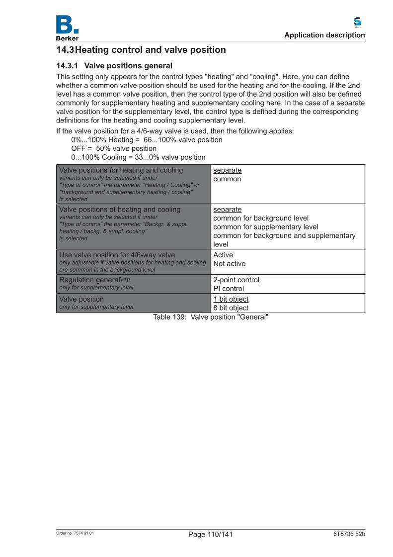
14.3 Heating control and valve position14.3.1 Valve positions generalThissettingonlyappearsforthecontroltypes"heating"and"cooling".Here,youcandefinewhether a common valve position should be used for the heating and for the cooling. If the 2nd levelhasacommonvalveposition,thenthecontroltypeofthe2ndpositionwillalsobedefinedcommonly for supplementary heating and supplementary cooling here. In the case of a separate valvepositionforthesupplementarylevel,thecontroltypeisdefinedduringthecorrespondingdefinitionsfortheheatingandcoolingsupplementarylevel.If the valve position for a 4/6-way valve is used, then the following applies:
0%...100% Heating = 66...100% valve positionOFF = 50% valve position0...100% Cooling = 33...0% valve position
Valve positions for heating and coolingvariants can only be selected if under"Type of control" the parameter "Heating / Cooling" or "Background and supplementary heating / cooling"is selected
separatecommon
Valve positions at heating and coolingvariants can only be selected if under"Type of control" the parameter "Backgr. & suppl. heating / backg. & suppl. cooling"is selected
separatecommon for background levelcommon for supplementary levelcommon for background and supplementary level
Use valve position for 4/6-way valveonly adjustable if valve positions for heating and cooling are common in the background level
ActiveNot active
Regulation general\r\nonly for supplementary level
2-point controlPI control
Valve position only for supplementary level
1 bit object8 bit object
Table 139: Valve position "General"
Application description
Page 110/141Order no. 7574 01 01 6T8736 52b
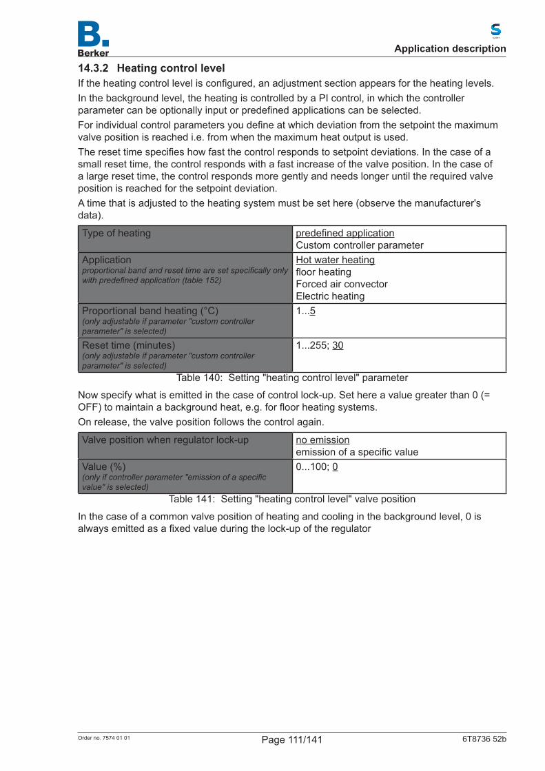
14.3.2 Heating control levelIftheheatingcontrollevelisconfigured,anadjustmentsectionappearsfortheheatinglevels.In the background level, the heating is controlled by a PI control, in which the controller parametercanbeoptionallyinputorpredefinedapplicationscanbeselected.Forindividualcontrolparametersyoudefineatwhichdeviationfromthesetpointthemaximumvalve position is reached i.e. from when the maximum heat output is used.Theresettimespecifieshowfastthecontrolrespondstosetpointdeviations.Inthecaseofasmall reset time, the control responds with a fast increase of the valve position. In the case of alargeresettime,thecontrolrespondsmoregentlyandneedslongeruntiltherequiredvalveposition is reached for the setpoint deviation.A time that is adjusted to the heating system must be set here (observe the manufacturer's data).
Type of heating predefinedapplicationCustom controller parameter
Applicationproportional band and reset time are set specifically only with predefined application (table 152)
Hot water heatingfloorheatingForced air convectorElectric heating
Proportional band heating (°C)(only adjustable if parameter "custom controller parameter" is selected)
1...5
Reset time (minutes)(only adjustable if parameter "custom controller parameter" is selected)
1...255; 30
Table 140: Setting "heating control level" parameter
Now specify what is emitted in the case of control lock-up. Set here a value greater than 0 (= OFF)tomaintainabackgroundheat,e.g.forfloorheatingsystems.On release, the valve position follows the control again.
Valve position when regulator lock-up no emissionemissionofaspecificvalue
Value (%)(only if controller parameter "emission of a specific value" is selected)
0...100; 0
Table 141: Setting "heating control level" valve position
In the case of a common valve position of heating and cooling in the background level, 0 is alwaysemittedasafixedvalueduringthelock-upoftheregulator
Application description
Page 111/141Order no. 7574 01 01 6T8736 52b
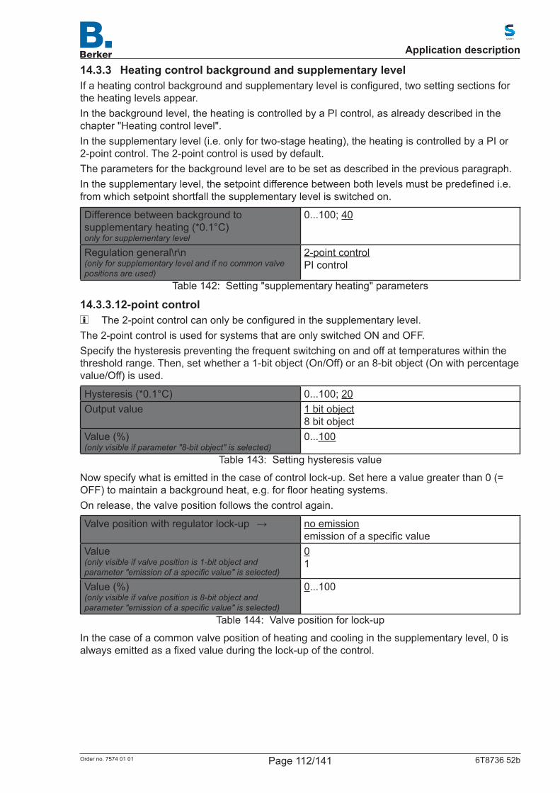
14.3.3 Heating control background and supplementary levelIfaheatingcontrolbackgroundandsupplementarylevelisconfigured,twosettingsectionsforthe heating levels appear.In the background level, the heating is controlled by a PI control, as already described in the chapter "Heating control level".In the supplementary level (i.e. only for two-stage heating), the heating is controlled by a PI or 2-point control. The 2-point control is used by default.The parameters for the background level are to be set as described in the previous paragraph.Inthesupplementarylevel,thesetpointdifferencebetweenbothlevelsmustbepredefinedi.e.from which setpoint shortfall the supplementary level is switched on.
Difference between background to supplementary heating (*0.1°C)only for supplementary level
0...100; 40
Regulation general\r\n(only for supplementary level and if no common valve positions are used)
2-point controlPI control
Table 142: Setting "supplementary heating" parameters
14.3.3.12-point control The2-pointcontrolcanonlybeconfiguredinthesupplementarylevel.
The 2-point control is used for systems that are only switched ON and OFF.Specifythehysteresispreventingthefrequentswitchingonandoffattemperatureswithinthethreshold range. Then, set whether a 1-bit object (On/Off) or an 8-bit object (On with percentage value/Off) is used.
Hysteresis (*0.1°C) 0...100; 20Output value 1 bit object
8 bit objectValue (%)(only visible if parameter "8-bit object" is selected)
0...100
Table 143: Setting hysteresis value
Now specify what is emitted in the case of control lock-up. Set here a value greater than 0 (= OFF)tomaintainabackgroundheat,e.g.forfloorheatingsystems.On release, the valve position follows the control again.
Valvepositionwithregulatorlock-up → no emissionemissionofaspecificvalue
Value(only visible if valve position is 1-bit object and parameter "emission of a specific value" is selected)
01
Value (%)(only visible if valve position is 8-bit object and parameter "emission of a specific value" is selected)
0...100
Table 144: Valve position for lock-up
In the case of a common valve position of heating and cooling in the supplementary level, 0 is alwaysemittedasafixedvalueduringthelock-upofthecontrol.
Application description
Page 112/141Order no. 7574 01 01 6T8736 52b
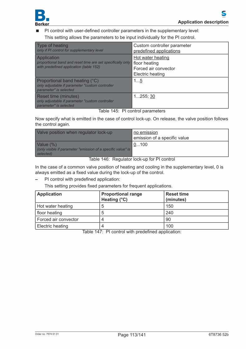
� PIcontrolwithuser-definedcontrollerparametersinthesupplementarylevel:This setting allows the parameters to be input individually for the PI control.
Type of heatingonly if PI control for supplementary level
Custom controller parameterpredefinedapplications
Applicationproportional band and reset time are set specifically only with predefined application (table 152)
Hot water heatingfloorheatingForced air convectorElectric heating
Proportional band heating (°C)only adjustable if parameter "custom controller parameter" is selected
1...5
Reset time (minutes)only adjustable if parameter "custom controller parameter" is selected
1...255; 30
Table 145: PI control parameters
Now specify what is emitted in the case of control lock-up. On release, the valve position follows the control again.
Valve position when regulator lock-up no emissionemissionofaspecificvalue
Value (%)(only visible if parameter "emission of a specific value" is selected)
0...100
Table 146: Regulator lock-up for PI control
In the case of a common valve position of heating and cooling in the supplementary level, 0 is alwaysemittedasafixedvalueduringthelock-upofthecontrol. – PIcontrolwithpredefinedapplication:
Thissettingprovidesfixedparametersforfrequentapplications.
Application Proportional rangeHeating (°C)
Reset time(minutes)
Hot water heating 5 150floorheating 5 240Forced air convector 4 90Electric heating 4 100
Table 147: PIcontrolwithpredefinedapplication:
Application description
Page 113/141Order no. 7574 01 01 6T8736 52b
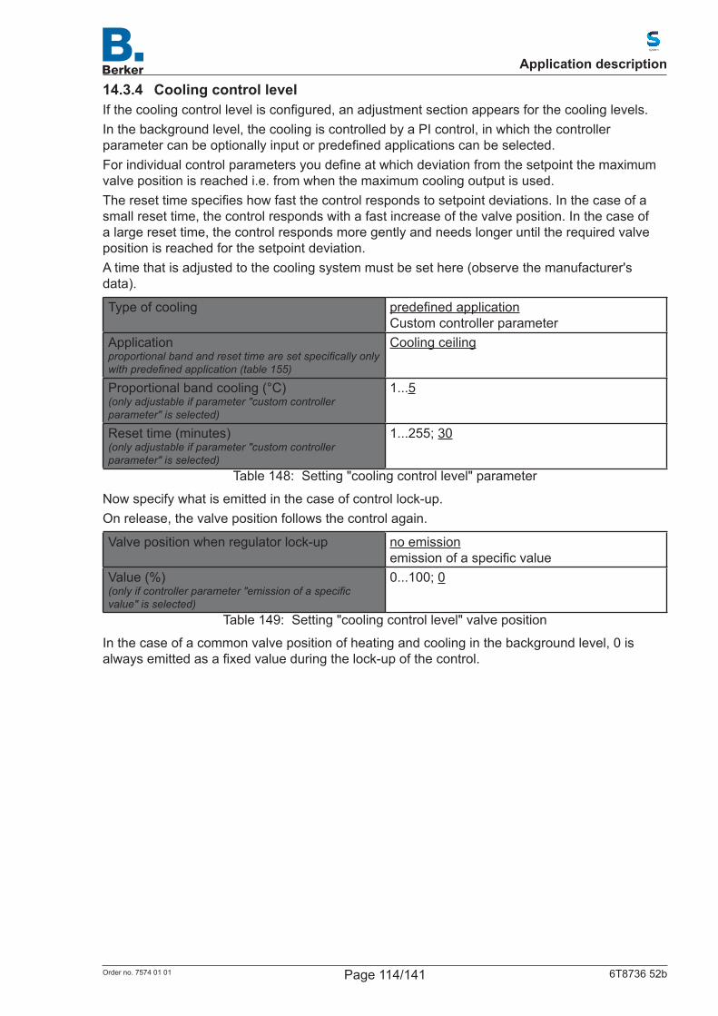
14.3.4 Cooling control levelIfthecoolingcontrollevelisconfigured,anadjustmentsectionappearsforthecoolinglevels.In the background level, the cooling is controlled by a PI control, in which the controller parametercanbeoptionallyinputorpredefinedapplicationscanbeselected.Forindividualcontrolparametersyoudefineatwhichdeviationfromthesetpointthemaximumvalve position is reached i.e. from when the maximum cooling output is used.Theresettimespecifieshowfastthecontrolrespondstosetpointdeviations.Inthecaseofasmall reset time, the control responds with a fast increase of the valve position. In the case of alargeresettime,thecontrolrespondsmoregentlyandneedslongeruntiltherequiredvalveposition is reached for the setpoint deviation.A time that is adjusted to the cooling system must be set here (observe the manufacturer's data).
Type of cooling predefinedapplicationCustom controller parameter
Applicationproportional band and reset time are set specifically only with predefined application (table 155)
Cooling ceiling
Proportional band cooling (°C)(only adjustable if parameter "custom controller parameter" is selected)
1...5
Reset time (minutes)(only adjustable if parameter "custom controller parameter" is selected)
1...255; 30
Table 148: Setting "cooling control level" parameter
Now specify what is emitted in the case of control lock-up.On release, the valve position follows the control again.
Valve position when regulator lock-up no emissionemissionofaspecificvalue
Value (%)(only if controller parameter "emission of a specific value" is selected)
0...100; 0
Table 149: Setting "cooling control level" valve position
In the case of a common valve position of heating and cooling in the background level, 0 is alwaysemittedasafixedvalueduringthelock-upofthecontrol.
Application description
Page 114/141Order no. 7574 01 01 6T8736 52b

14.3.5 Cooling control background and supplementary levelIfacoolingcontrolbackgroundandsupplementarylevelisconfigured,twosettingsectionsforthe cooling levels appear.In the background level, the cooling is controlled by a PI control, as already described above under Cooling control level.In the supplementary level (i.e. only for two-stage cooling), the cooling is controlled by a PI or 2-point control. The 2-point control is used by default.The parameters for the background level are to be set as described in the previous paragraph.Inthesupplementarylevel,thesetpointdifferencebetweenbothlevelsmustbepredefinedi.e.from which setpoint shortfall the 2nd level is switched on.
Difference between background to supplementary heating (*0.1°C)only for supplementary level
0...100; 40
Regulation general\r\n(only for supplementary level and if no common valve positions are used)
2-point controlPI control
Table 150: Setting "supplementary cooling" parameter
14.3.5.12-point controlThe2-pointcontrolcanonlybeconfiguredinthesupplementarylevel.The 2-point control is used for systems that are only switched ON and OFF.Specifythehysteresispreventingthefrequentswitchingonandoffattemperatureswithinthethreshold range. Then, set whether a 1-bit object (On/Off) or an 8-bit object (On with percentage value/Off) is used.
Hysteresis (*0.1°C) 0...100; 20Output value 1 bit object
8 bit objectValue (%)(only visible if parameter "8-bit object" is selected)
0...100
Table 151: Setting hysteresis value
Now specify what is emitted in the case of control lock-up.On release, the valve position follows the control again.
Valve position when regulator lock-up no emissionemissionofaspecificvalue
Value(only visible if valve position is 1-bit object and parameter "emission of a specific value" is selected)
01
Value (%)(only visible if valve position is 8-bit object and parameter "emission of a specific value" is selected)
0...100
Table 152: Lock-up valve position
In the case of a common valve position of heating and cooling in the supplementary level, 0 is alwaysemittedasafixedvalueduringthelock-upofthecontrol.
Application description
Page 115/141Order no. 7574 01 01 6T8736 52b
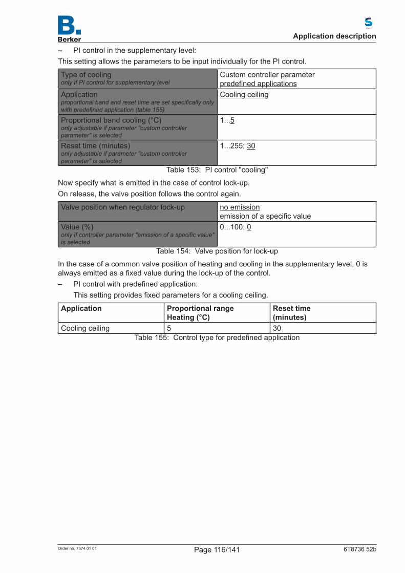
– PI control in the supplementary level:This setting allows the parameters to be input individually for the PI control.
Type of coolingonly if PI control for supplementary level
Custom controller parameterpredefinedapplications
Applicationproportional band and reset time are set specifically only with predefined application (table 155)
Cooling ceiling
Proportional band cooling (°C)only adjustable if parameter "custom controller parameter" is selected
1...5
Reset time (minutes)only adjustable if parameter "custom controller parameter" is selected
1...255; 30
Table 153: PI control "cooling"
Now specify what is emitted in the case of control lock-up.On release, the valve position follows the control again.
Valve position when regulator lock-up no emissionemissionofaspecificvalue
Value (%)only if controller parameter "emission of a specific value" is selected
0...100; 0
Table 154: Valve position for lock-up
In the case of a common valve position of heating and cooling in the supplementary level, 0 is alwaysemittedasafixedvalueduringthelock-upofthecontrol. – PIcontrolwithpredefinedapplication:
Thissettingprovidesfixedparametersforacoolingceiling.
Application Proportional rangeHeating (°C)
Reset time(minutes)
Cooling ceiling 5 30Table 155: Controltypeforpredefinedapplication
Application description
Page 116/141Order no. 7574 01 01 6T8736 52b
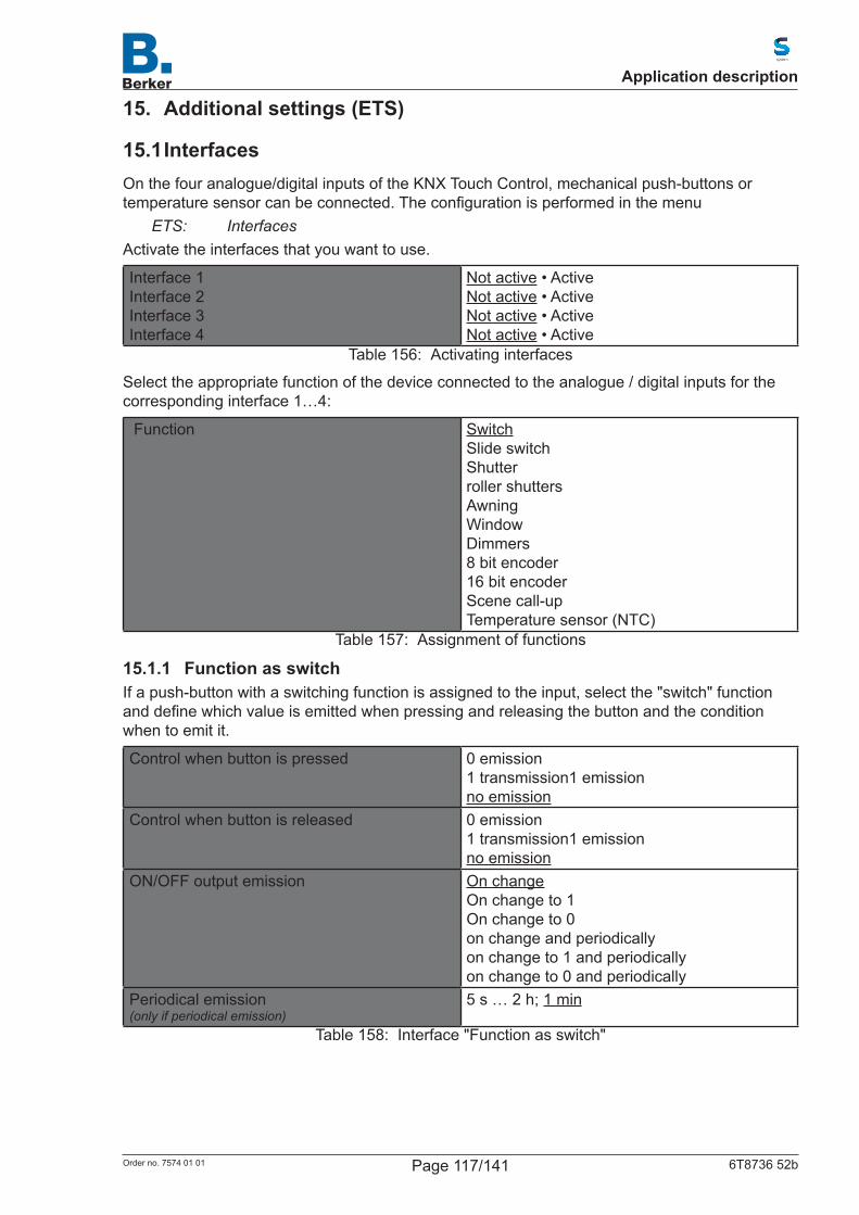
15. Additional settings (ETS)
15.1 InterfacesOn the four analogue/digital inputs of the KNX Touch Control, mechanical push-buttons or temperaturesensorcanbeconnected.Theconfigurationisperformedinthemenu
ETS: InterfacesActivate the interfaces that you want to use.
Interface 1Interface 2Interface 3Interface 4
Not active • ActiveNot active • ActiveNot active • ActiveNot active • Active
Table 156: Activating interfaces
Select the appropriate function of the device connected to the analogue / digital inputs for the corresponding interface 1…4:
Function SwitchSlide switchShutterroller shuttersAwningWindowDimmers8 bit encoder16 bit encoderScene call-upTemperature sensor (NTC)
Table 157: Assignment of functions
15.1.1 Function as switchIf a push-button with a switching function is assigned to the input, select the "switch" function anddefinewhichvalueisemittedwhenpressingandreleasingthebuttonandtheconditionwhen to emit it.
Control when button is pressed 0 emission1 transmission1 emissionno emission
Control when button is released 0 emission1 transmission1 emissionno emission
ON/OFF output emission On changeOn change to 1On change to 0on change and periodicallyon change to 1 and periodicallyon change to 0 and periodically
Periodical emission(only if periodical emission)
5 s … 2 h; 1 min
Table 158: Interface "Function as switch"
Application description
Page 117/141Order no. 7574 01 01 6T8736 52b
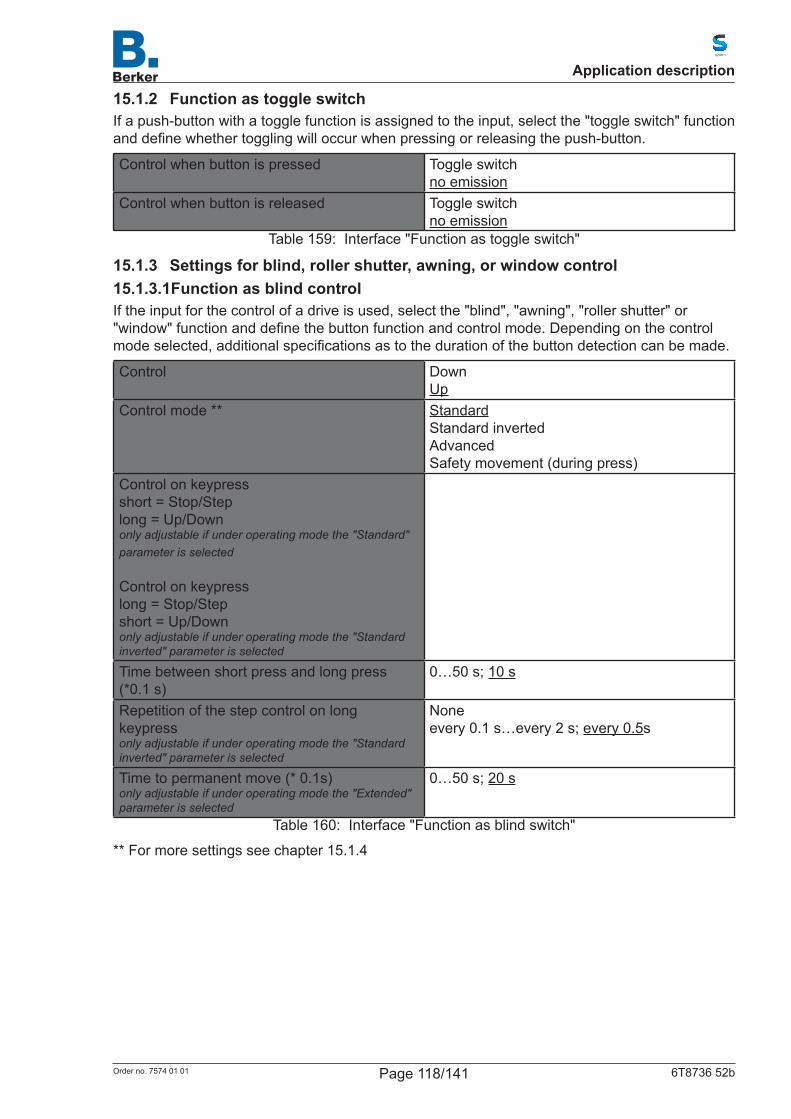
15.1.2 Function as toggle switchIf a push-button with a toggle function is assigned to the input, select the "toggle switch" function anddefinewhethertogglingwilloccurwhenpressingorreleasingthepush-button.
Control when button is pressed Toggle switchno emission
Control when button is released Toggle switchno emission
Table 159: Interface "Function as toggle switch"
15.1.3 Settings for blind, roller shutter, awning, or window control15.1.3.1Function as blind controlIf the input for the control of a drive is used, select the "blind", "awning", "roller shutter" or "window"functionanddefinethebuttonfunctionandcontrolmode.Dependingonthecontrolmodeselected,additionalspecificationsastothedurationofthebuttondetectioncanbemade.
Control DownUp
Control mode ** StandardStandard invertedAdvancedSafety movement (during press)
Control on keypress short = Stop/Steplong = Up/Downonly adjustable if under operating mode the "Standard" parameter is selected
Control on keypress long = Stop/Stepshort = Up/Downonly adjustable if under operating mode the "Standard inverted" parameter is selected
Time between short press and long press(*0.1 s)
0…50 s; 10 s
Repetition of the step control on long keypressonly adjustable if under operating mode the "Standard inverted" parameter is selected
Noneevery 0.1 s…every 2 s; every 0.5s
Time to permanent move (* 0.1s)only adjustable if under operating mode the "Extended" parameter is selected
0…50 s; 20 s
Table 160: Interface "Function as blind switch"
** For more settings see chapter 15.1.4
Application description
Page 118/141Order no. 7574 01 01 6T8736 52b

15.1.3.2Function as roller shutter controlControl Up
DownUp/down
Control mode ** StandardStandard invertedAdvancedSafety movement (during press)
Control on keypress short = Stoplong = Up/Downonly adjustable if under operating mode the"Standard" parameter is selected
Control on keypress long = Stopshort = Up/Downonly adjustable if under operating mode the"Standard inverted" parameter is selected
Time between short press and long press(*0.1 s)
0…50 s; 10 s
Repetition of the step control on long keypressonly adjustable if under operating mode the "Standard inverted" parameter is selected
Noneevery 0.1 s…every 2 s; every 0.5s
Time to permanent move (* 0.1s)only adjustable if under operating mode the "Extended" parameter is selected
0…50 s; 20 s
Table 161: Interface "Function as roller shutter switch"
** For more settings see chapter 15.1.4
Application description
Page 119/141Order no. 7574 01 01 6T8736 52b

15.1.3.3Function as awning controlControl Up
DownUp/down
Control mode ** StandardStandard invertedAdvanced Safety movement (during press)
Control on keypress short = Stoplong = Up/Downonly adjustable if under operating mode the"Standard" parameter is selected
Control on keypress long = Stopshort = Up/Downonly adjustable if under operating mode the"Standard inverted" parameter is selected
Time between short press and long press(*0.1 s)
0…50 s; 10 s
Repetition of the step control on long keypressonly adjustable if under operating mode the "Standard inverted" parameter is selected
Noneevery 0.1 s…every 2 s; every 0.5s
Time to permanent move (* 0.1s)only adjustable if under operating mode the "Extended" parameter is selected
0…50 s; 20 s
Table 162: Interface "Function as awning control"
** For more settings see chapter 15.1.4
Application description
Page 120/141Order no. 7574 01 01 6T8736 52b
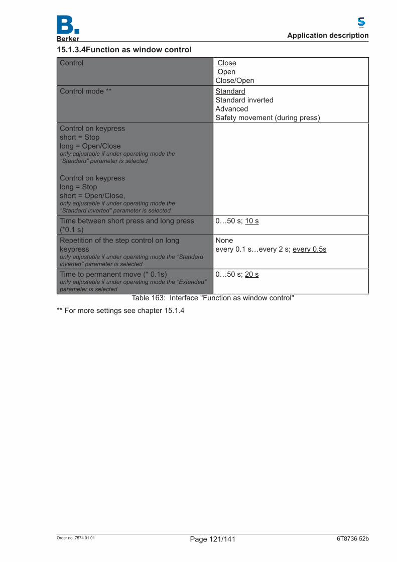
15.1.3.4Function as window controlControl Close
OpenClose/Open
Control mode ** StandardStandard invertedAdvanced Safety movement (during press)
Control on keypress short = Stoplong = Open/Closeonly adjustable if under operating mode the"Standard" parameter is selected
Control on keypress long = Stopshort = Open/Close, only adjustable if under operating mode the"Standard inverted" parameter is selected
Time between short press and long press (*0.1 s)
0…50 s; 10 s
Repetition of the step control on long keypressonly adjustable if under operating mode the "Standard inverted" parameter is selected
Noneevery 0.1 s…every 2 s; every 0.5s
Time to permanent move (* 0.1s)only adjustable if under operating mode the "Extended" parameter is selected
0…50 s; 20 s
Table 163: Interface "Function as window control"
** For more settings see chapter 15.1.4
Application description
Page 121/141Order no. 7574 01 01 6T8736 52b
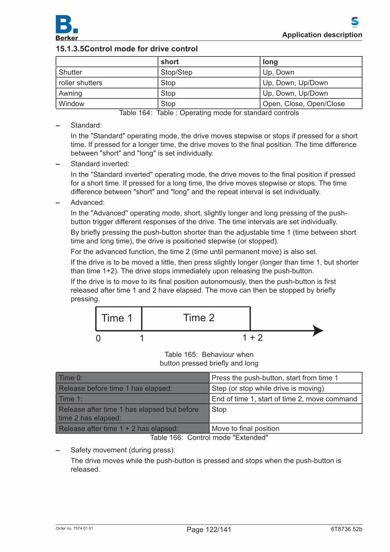
15.1.3.5Control mode for drive controlshort long
Shutter Stop/Step Up, Downroller shutters Stop Up, Down, Up/DownAwning Stop Up, Down, Up/DownWindow Stop Open, Close, Open/Close
Table 164: Table : Operating mode for standard controls
– Standard:In the "Standard" operating mode, the drive moves stepwise or stops if pressed for a short time.Ifpressedforalongertime,thedrivemovestothefinalposition.Thetimedifferencebetween "short" and "long" is set individually.
– Standard inverted:Inthe"Standardinverted"operatingmode,thedrivemovestothefinalpositionifpressedfor a short time. If pressed for a long time, the drive moves stepwise or stops. The time difference between "short" and "long" and the repeat interval is set individually.
– Advanced:In the "Advanced" operating mode, short, slightly longer and long pressing of the push-button trigger different responses of the drive. The time intervals are set individually.Bybrieflypressingthepush-buttonshorterthantheadjustabletime1(timebetweenshorttime and long time), the drive is positioned stepwise (or stopped).For the advanced function, the time 2 (time until permanent move) is also set.If the drive is to be moved a little, then press slightly longer (longer than time 1, but shorter than time 1+2). The drive stops immediately upon releasing the push-button.Ifthedriveistomovetoitsfinalpositionautonomously,thenthepush-buttonisfirstreleasedaftertime1and2haveelapsed.Themovecanthenbestoppedbybrieflypressing.
Time 1 Time 2
0 1 1 + 2
Table 165: Behaviour when buttonpressedbrieflyandlong
Time 0: Press the push-button, start from time 1Release before time 1 has elapsed: Step (or stop while drive is moving)Time 1: End of time 1, start of time 2, move commandRelease after time 1 has elapsed but before time 2 has elapsed:
Stop
Release after time 1 + 2 has elapsed: MovetofinalpositionTable 166: Control mode "Extended"
– Safety movement (during press):The drive moves while the push-button is pressed and stops when the push-button is released.
Application description
Page 122/141Order no. 7574 01 01 6T8736 52b

15.1.4 Function as dimmerIftheinputisusedasadimmer,selectthe"Dimmer"functionanddefinethebuttonfunction,timeinterval(switching/dimming),andifrequired,therepetitionintervalonlongkeypress.
Control Increase (ON)Decrease (OFF)Increase (ON)/decrease (OFF)
Time between switching and dimming(*0.1 s)
1...50; 5
Repetition of the dimming control Not activeActive
Periodical emission on long keypress (only if "Repetition of the dimming control" is set to active)
every 0.1 s... • every 2 s; every 0.5 s
Periodical emission on long keypress (only if "Repetition of the dimming control" is set to active)
1.50%; 3%; 6 %; 12.50%; 25%; 50%
Table 167: Control mode "Function as dimmer"
15.1.5 Function as 8-bit value transmitterIf the input should be used as an 8-bit value transmitter, select the "8-bit value transmitter" functionanddefinewhichvalueisemitted.
Object type 8 bit → 0...2558bit→0...100%8bit→0°...360°
Value 0...255; 0 (for value range 0...255)0...100; 0 (for value range 0%...100%)0...360; 0 (for value range 0°...360°)
Table 168: Control mode "Function as 8-bit value transmitter"
15.1.6 Function as 16-bit value transmitterIf the input should be used as an 16-bit value transmitter, select the "16-bit value transmitter" functionanddefinewhichvalueisemitted.
Function 16 bit encoderValue (*0.1) -6707600...6707600; 0
Table 169: Control mode "Function as 16-bit value transmitter"
15.1.7 Function as scene controlIfasceneistobecalledupandsaved,thenselectthe"Scenecall-up"functionanddefinewhether the push-button should also be used for storing the scene (press longer).
Function Scene call-upScene number 0...63Store scene by long key-press Not active
ActiveDuration to long press (*0.1s)(only visible if "Store scene by long key-press" is set to active)
0...50
Table 170: Control mode "Function for scene control"
Application description
Page 123/141Order no. 7574 01 01 6T8736 52b

15.1.8 Temperature sensor (NTC)If a temperature sensor NTC is to be connected to the input, set the behaviour (malfunction object, transmission behaviour) and mixed value calculation. If the measured values of the sensor deviate from the actual temperature values (e.g. at an unfavourable mounting location), this can be corrected by an offset.
Function Temperature sensor (NTC)Malfunction object Active
Not activeOffset (*0.1°C) -50 ...
50; 0External measured value Active
Not activeMeasured value proportion,\r\ninternal to externalonly if external value is used
95% to 5%90% to 10%.50% to 50%.10% to 90%5% to 95%0% to 100%
All of the following settings then pertain to the total measured value.Measured value emission Periodically
On changeon change and periodically
onchangegreaterthan/equaltoif emission on change
0.1°C ... 0.5°C ... 5.0°C
Periodical emission(if parameter "Measured value emission" is set to periodical)
5 s...2 h
Table 171: Control mode "Temperature sensor NTC"
Application description
Page 124/141Order no. 7574 01 01 6T8736 52b
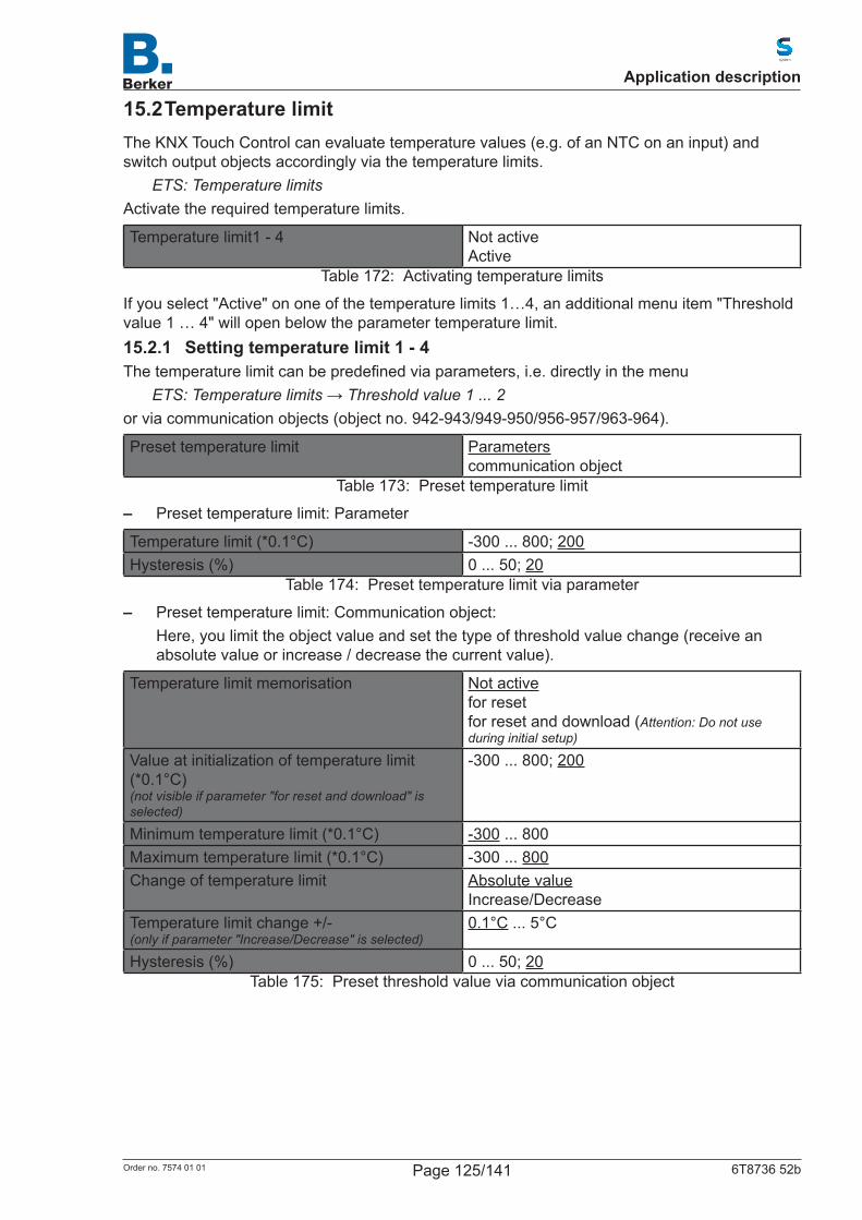
15.2 Temperature limitThe KNX Touch Control can evaluate temperature values (e.g. of an NTC on an input) and switch output objects accordingly via the temperature limits.
ETS: Temperature limitsActivatetherequiredtemperaturelimits.
Temperature limit1 - 4 Not activeActive
Table 172: Activating temperature limits
If you select "Active" on one of the temperature limits 1…4, an additional menu item "Threshold value 1 … 4" will open below the parameter temperature limit.15.2.1 Setting temperature limit 1 - 4Thetemperaturelimitcanbepredefinedviaparameters,i.e.directlyinthemenu
ETS: Temperature limits → Threshold value 1 ... 2or via communication objects (object no. 942-943/949-950/956-957/963-964).
Preset temperature limit Parameterscommunication object
Table 173: Preset temperature limit
– Preset temperature limit: Parameter
Temperature limit (*0.1°C) -300 ... 800; 200Hysteresis (%) 0 ... 50; 20
Table 174: Preset temperature limit via parameter
– Preset temperature limit: Communication object:Here, you limit the object value and set the type of threshold value change (receive an absolute value or increase / decrease the current value).
Temperature limit memorisation Not activefor resetfor reset and download (Attention: Do not use during initial setup)
Value at initialization of temperature limit (*0.1°C)(not visible if parameter "for reset and download" is selected)
-300 ... 800; 200
Minimum temperature limit (*0.1°C) -300 ... 800Maximum temperature limit (*0.1°C) -300 ... 800Change of temperature limit Absolute value
Increase/DecreaseTemperature limit change +/-(only if parameter "Increase/Decrease" is selected)
0.1°C ... 5°C
Hysteresis (%) 0 ... 50; 20Table 175: Preset threshold value via communication object
Application description
Page 125/141Order no. 7574 01 01 6T8736 52b
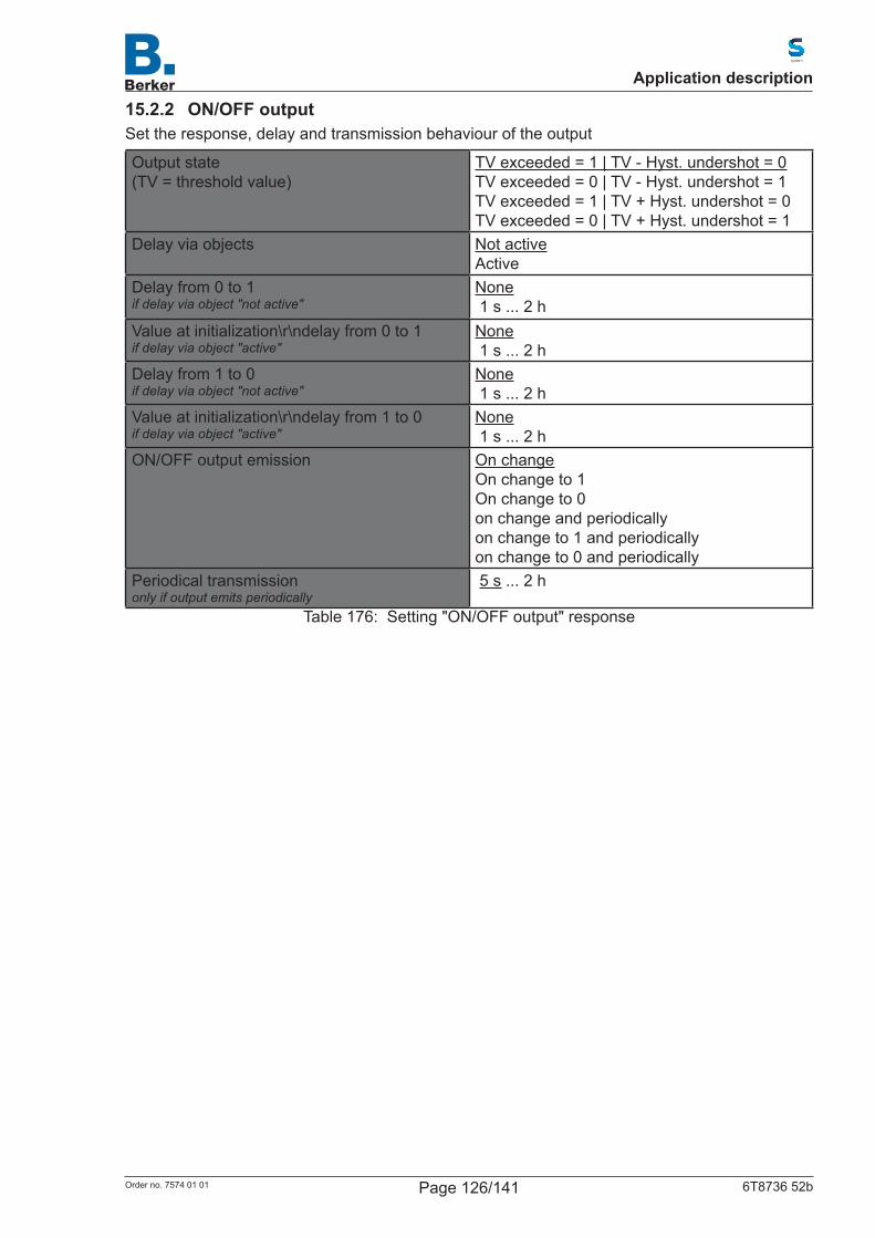
15.2.2 ON/OFF outputSet the response, delay and transmission behaviour of the output
Output state(TV = threshold value)
TV exceeded = 1 | TV - Hyst. undershot = 0TV exceeded = 0 | TV - Hyst. undershot = 1TV exceeded = 1 | TV + Hyst. undershot = 0TV exceeded = 0 | TV + Hyst. undershot = 1
Delay via objects Not activeActive
Delay from 0 to 1if delay via object "not active"
None 1 s ... 2 h
Value at initialization\r\ndelay from 0 to 1if delay via object "active"
None 1 s ... 2 h
Delay from 1 to 0if delay via object "not active"
None 1 s ... 2 h
Value at initialization\r\ndelay from 1 to 0if delay via object "active"
None 1 s ... 2 h
ON/OFF output emission On changeOn change to 1On change to 0on change and periodicallyon change to 1 and periodicallyon change to 0 and periodically
Periodical transmissiononly if output emits periodically
5 s ... 2 h
Table 176: Setting "ON/OFF output" response
Application description
Page 126/141Order no. 7574 01 01 6T8736 52b
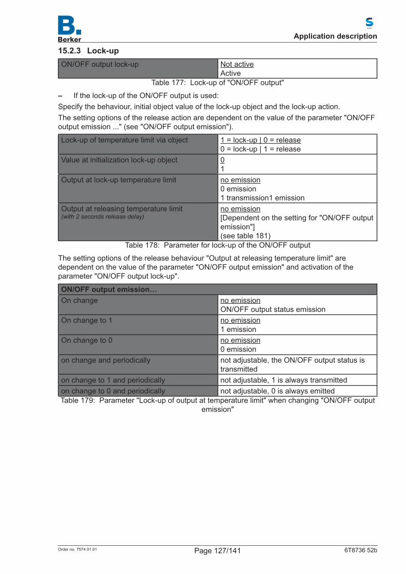
15.2.3 Lock-upON/OFF output lock-up Not active
ActiveTable 177: Lock-up of "ON/OFF output"
– If the lock-up of the ON/OFF output is used:Specify the behaviour, initial object value of the lock-up object and the lock-up action.The setting options of the release action are dependent on the value of the parameter "ON/OFF output emission ..." (see "ON/OFF output emission").
Lock-up of temperature limit via object 1 = lock-up | 0 = release0 = lock-up | 1 = release
Value at initialization lock-up object 01
Output at lock-up temperature limit no emission0 emission1 transmission1 emission
Output at releasing temperature limit(with 2 seconds release delay)
no emission[Dependent on the setting for "ON/OFF output emission"](see table 181)
Table 178: Parameter for lock-up of the ON/OFF output
The setting options of the release behaviour "Output at releasing temperature limit" are dependent on the value of the parameter "ON/OFF output emission" and activation of the parameter "ON/OFF output lock-up".
ON/OFF output emission…On change no emission
ON/OFF output status emissionOn change to 1 no emission
1 emissionOn change to 0 no emission
0 emissionon change and periodically not adjustable, the ON/OFF output status is
transmittedon change to 1 and periodically not adjustable, 1 is always transmittedon change to 0 and periodically not adjustable, 0 is always emittedTable 179: Parameter "Lock-up of output at temperature limit" when changing "ON/OFF output
emission"
Application description
Page 127/141Order no. 7574 01 01 6T8736 52b

15.3 Scene controlConfigurescenesthatarethencalledupviaobjectsandcanalsobechanged.
ETS: Scene controlIf you select "Active" on one of the scene objects 1…16, an additional menu item will open below the parameter scene object X.
Firstactivatetherequirednumberofsceneobjects(upto16objects,no.862-877).
Scene object 1 -16 Not activeActive
Table 180: Selection of scene objects
15.3.1 Scene object 1-16If you select "Active" on one of the scene objects 1…16, an additional menu item will open below the parameter scene object X.Firstactivatetherequirednumberofsceneobjects(upto16objects,no.862-877).
Object value after restart Initial valueValue before restart
Object type 1 bits8-bit value [0...255]8-bit value [0...100]8-bit value [0...360]16bitfloatingpoint
Table 181: Assigning parameters for scene object
These scene objects (e.g. the dimming linked with the living room light) can now be assigned totheindividualscenes(1...16)anddefinedwithavalue.Asaresult,alinkcanbeusedrepeatedly (e.g. dimming to 20% for scene "television", diming to 60% for scene "guest").
Application description
Page 128/141Order no. 7574 01 01 6T8736 52b
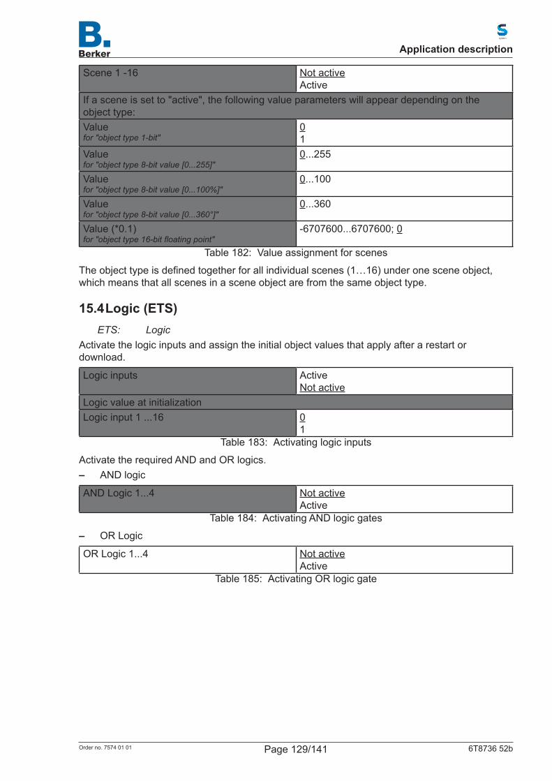
Scene 1 -16 Not activeActive
If a scene is set to "active", the following value parameters will appear depending on the object type:Valuefor "object type 1-bit"
01
Valuefor "object type 8-bit value [0...255]"
0...255
Valuefor "object type 8-bit value [0...100%]"
0...100
Valuefor "object type 8-bit value [0...360°]"
0...360
Value (*0.1)for "object type 16-bit floating point"
-6707600...6707600; 0
Table 182: Value assignment for scenes
Theobjecttypeisdefinedtogetherforallindividualscenes(1…16)underonesceneobject,which means that all scenes in a scene object are from the same object type.
15.4 Logic (ETS)ETS: Logic
Activate the logic inputs and assign the initial object values that apply after a restart or download.
Logic inputs ActiveNot active
Logic value at initializationLogic input 1 ...16 0
1Table 183: Activating logic inputs
ActivatetherequiredANDandORlogics. – AND logic
AND Logic 1...4 Not activeActive
Table 184: Activating AND logic gates
– OR Logic
OR Logic 1...4 Not activeActive
Table 185: Activating OR logic gate
Application description
Page 129/141Order no. 7574 01 01 6T8736 52b

15.4.1 AND Logic 1/2/3/4 and OR Logic 1/2/3/4The same setting options are available for the AND and OR logic.Eachlogicoutputcanemita1-bitobjectortwo8-bitobjects.Definewhattheoutputemitsiflogic = 1 and if logic = 0 in each case.A logic input 1 … 16 must be assigned to each input (1.; 2.; 3.; 4.;), but at least two.
1. Input2. Input3. Input4. Input
Not activeLogic input 1 ... 16Logic input 1 ... 16 inverted
Logic output a 1-bit objecttwo 8-bit objects
Table 186: Setting options for the logic gates
– Logic output emits a 1-bit object:
Object value if logic output = 1 10
Object value if logic output = 0 10
Logic output sends By logic result value changeBy logic result value change to 1By logic result value change to 0By logic result value change and periodicallyBy logic result value change to 1 and periodicallyBy logic result value change to 0 and periodicallyby input value change\nBy input change and periodically
Table 187: Transmission behaviour with 1-bit object
– Logic output emits two 8-bit objects:
Object type Value [0…255]Value [0…100%]Value [0…360°]Scene call-up
Table 188: Transmission behaviour with two 8-bit objects
Object value A if logic result = 1Value Value 0 … 255; 1
Percentage 0 … 100%; 1%Angle 0 … 360°; 1°Scene call-up 0 … 127; 1
Table 189: Object value A if logic result = 1
Object value A if logic result = 0Value Value 0 … 255; 1
Percentage 0 … 100%; 1%Angle 0 … 360°; 1°Scene call-up 0 … 127; 1
Table 190: Object value A if logic result = 0
Application description
Page 130/141Order no. 7574 01 01 6T8736 52b

Object value B if logic result = 1Value Value 0 … 255; 1
Percentage 0 … 100%; 1%Angle 0 … 360°; 1°Scene call-up 0 … 127; 1
Table 191: Object value B with logic output =1
Object value B if logic result = 0Value Value 0 … 255; 1
Percentage 0 … 100%; 1%Angle 0 … 360°; 1°Scene call-up 0 … 127; 1
Table 192: Object value B with logic output =0
Example: Objects for shading controlObject A: Shading position height (0 = safe position, 255 = fully extended).Object B: Shading position slat angle (255 = 100% closed, 200 = approx. 80% closed).
Logic output sends By logic result value changeBy logic result value change 1By logic result value change 0By logic result value change and periodicallyBy logic result value change to 1 and periodicallyBy logic result value change to 0 and periodicallyby input value change\nBy input change and periodically
Periodical emission(only if emitted periodically)
5 s 10 s ... 2 h
Table 193: Transmission behaviour of the logic gate
15.4.1.1Lock-upSpecify the behaviour, initial object value of the lock-up object and the lock-up behaviour.
Lock-up logic via object 1 = lock-up | 0 = release0 = lock-up | 1 = release
Value at initialization lock-up object 01
Behaviour of the outputLogic output after lock-up no emission
Transmit object value if logic result = 0 Transmit object value if logic result = 1
Logic output after authorisation(with 2 seconds release delay)
[dependent on the setting for "Logic output emits"](see table 195)
Table 194: Blockingbehaviourbeforefirstcommunication
Application description
Page 131/141Order no. 7574 01 01 6T8736 52b

The setting options of the release behaviour "Logic output after authorisation" are dependent on the value of the parameter "Logic output emits".
Logic output emits…By logic result value change no emission
Transmit object value of current logic resultBy logic result value change to 1 no emission
Emission object value if logic result = 1By logic result value change to 0 no emission
Transmit object value if logic result = 0By logic result value change and periodically not adjustable, the object value of the current
logic result is emittedBy logic result value change to 1 and periodically
not adjustable, the object value is always transmitted if logic output = 1
By logic result value change to 0 and periodically
not adjustable, the object value is always transmitted if logic output = 0
By logic result value change to 0 and periodically
no emissionTransmit object value of current logic result
on input change and periodically not adjustable, the object value of the current logic result is emitted
Table 195: Transmission behaviour of the logic outputs
Application description
Page 132/141Order no. 7574 01 01 6T8736 52b
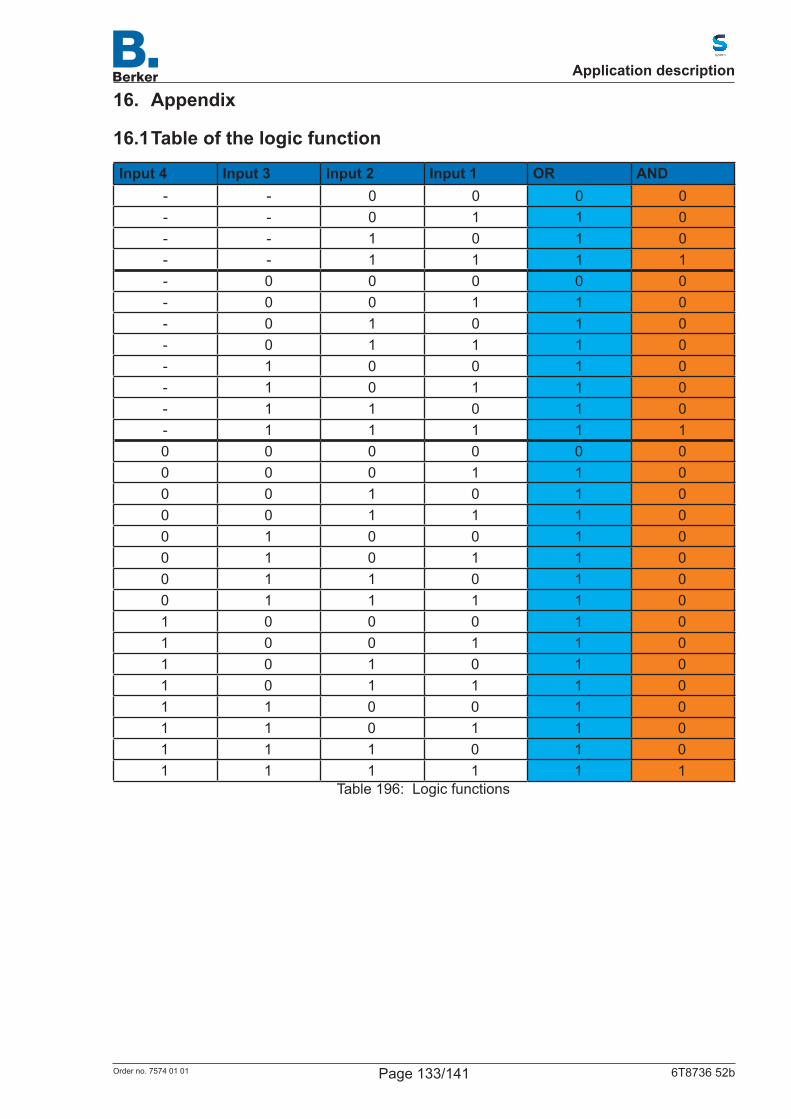
16. Appendix
16.1 Table of the logic function
Input 4 Input 3 Input 2 Input 1 OR AND- - 0 0 0 0- - 0 1 1 0- - 1 0 1 0- - 1 1 1 1- 0 0 0 0 0- 0 0 1 1 0- 0 1 0 1 0- 0 1 1 1 0- 1 0 0 1 0- 1 0 1 1 0- 1 1 0 1 0- 1 1 1 1 10 0 0 0 0 00 0 0 1 1 00 0 1 0 1 00 0 1 1 1 00 1 0 0 1 00 1 0 1 1 00 1 1 0 1 00 1 1 1 1 01 0 0 0 1 01 0 0 1 1 01 0 1 0 1 01 0 1 1 1 01 1 0 0 1 01 1 0 1 1 01 1 1 0 1 01 1 1 1 1 1
Table 196: Logic functions
Application description
Page 133/141Order no. 7574 01 01 6T8736 52b
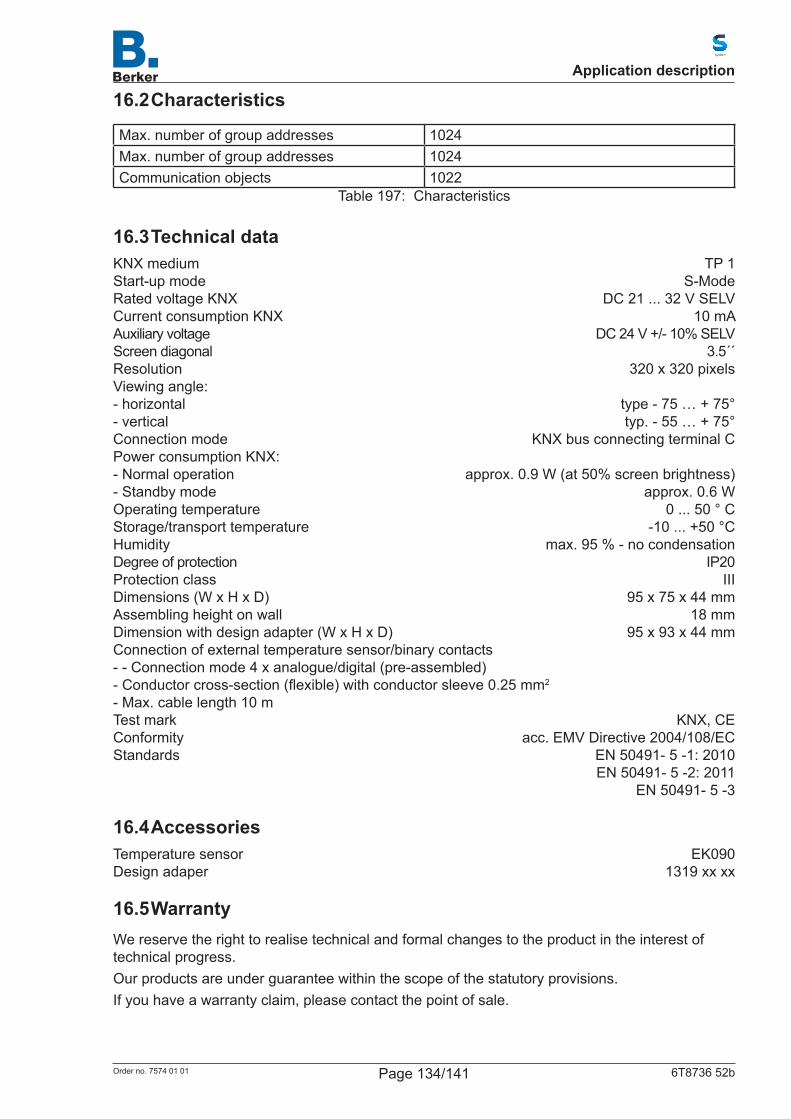
16.2 Characteristics
Max. number of group addresses 1024Max. number of group addresses 1024Communication objects 1022
Table 197: Characteristics
16.3 Technical dataKNX medium TP 1Start-up mode S-ModeRated voltage KNX DC 21 ... 32 V SELVCurrent consumption KNX 10 mAAuxiliary voltage DC 24 V +/- 10% SELVScreen diagonal 3.5´´Resolution 320 x 320 pixelsViewing angle:- horizontal type - 75 … + 75°- vertical typ. - 55 … + 75°Connection mode KNX bus connecting terminal CPower consumption KNX: - Normal operation approx. 0.9 W (at 50% screen brightness)- Standby mode approx. 0.6 WOperating temperature 0 ... 50 ° CStorage/transport temperature -10 ... +50 °CHumidity max. 95 % - no condensationDegree of protection IP20Protection class IIIDimensions (W x H x D) 95 x 75 x 44 mmAssembling height on wall 18 mmDimension with design adapter (W x H x D) 95 x 93 x 44 mmConnection of external temperature sensor/binary contacts - - Connection mode 4 x analogue/digital (pre-assembled) -Conductorcross-section(flexible)withconductorsleeve0.25mm2
- Max. cable length 10 m Test mark KNX, CEConformity acc. EMV Directive 2004/108/ECStandards EN 50491- 5 -1: 2010 EN 50491- 5 -2: 2011 EN 50491- 5 -3
16.4 AccessoriesTemperature sensor EK090Design adaper 1319 xx xx
16.5 WarrantyWe reserve the right to realise technical and formal changes to the product in the interest of technical progress.Our products are under guarantee within the scope of the statutory provisions.If you have a warranty claim, please contact the point of sale.
Application description
Page 134/141Order no. 7574 01 01 6T8736 52b
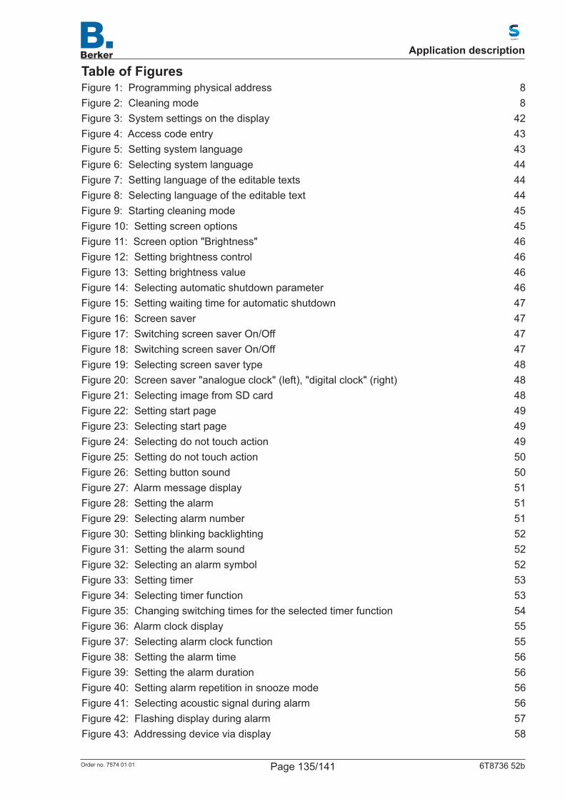
Table of FiguresFigure 1: Programming physical address 8Figure 2: Cleaning mode 8Figure 3: System settings on the display 42Figure 4: Access code entry 43Figure 5: Setting system language 43Figure 6: Selecting system language 44Figure 7: Setting language of the editable texts 44Figure 8: Selecting language of the editable text 44Figure 9: Starting cleaning mode 45Figure 10: Setting screen options 45Figure 11: Screen option "Brightness" 46Figure 12: Setting brightness control 46Figure 13: Setting brightness value 46Figure 14: Selecting automatic shutdown parameter 46Figure 15: Setting waiting time for automatic shutdown 47Figure 16: Screen saver 47Figure 17: Switching screen saver On/Off 47Figure 18: Switching screen saver On/Off 47Figure 19: Selecting screen saver type 48Figure 20: Screen saver "analogue clock" (left), "digital clock" (right) 48Figure 21: Selecting image from SD card 48Figure 22: Setting start page 49Figure 23: Selecting start page 49Figure 24: Selecting do not touch action 49Figure 25: Setting do not touch action 50Figure 26: Setting button sound 50Figure 27: Alarm message display 51Figure 28: Setting the alarm 51Figure 29: Selecting alarm number 51Figure 30: Setting blinking backlighting 52Figure 31: Setting the alarm sound 52Figure 32: Selecting an alarm symbol 52Figure 33: Setting timer 53Figure 34: Selecting timer function 53Figure 35: Changing switching times for the selected timer function 54Figure 36: Alarm clock display 55Figure 37: Selecting alarm clock function 55Figure 38: Setting the alarm time 56Figure 39: Setting the alarm duration 56Figure 40: Setting alarm repetition in snooze mode 56Figure 41: Selecting acoustic signal during alarm 56Figure 42: Flashing display during alarm 57Figure 43: Addressing device via display 58
Application description
Page 135/141Order no. 7574 01 01 6T8736 52b
Figure 44: Selecting page on the display 59Figure 45: Creating display surface individually 61Figure46: Configuringrocker 63Figure47: Configurationofrotarycontrol 65Figure48: Overviewofpredefinedpages 72
Application description
Page 136/141Order no. 7574 01 01 6T8736 52b
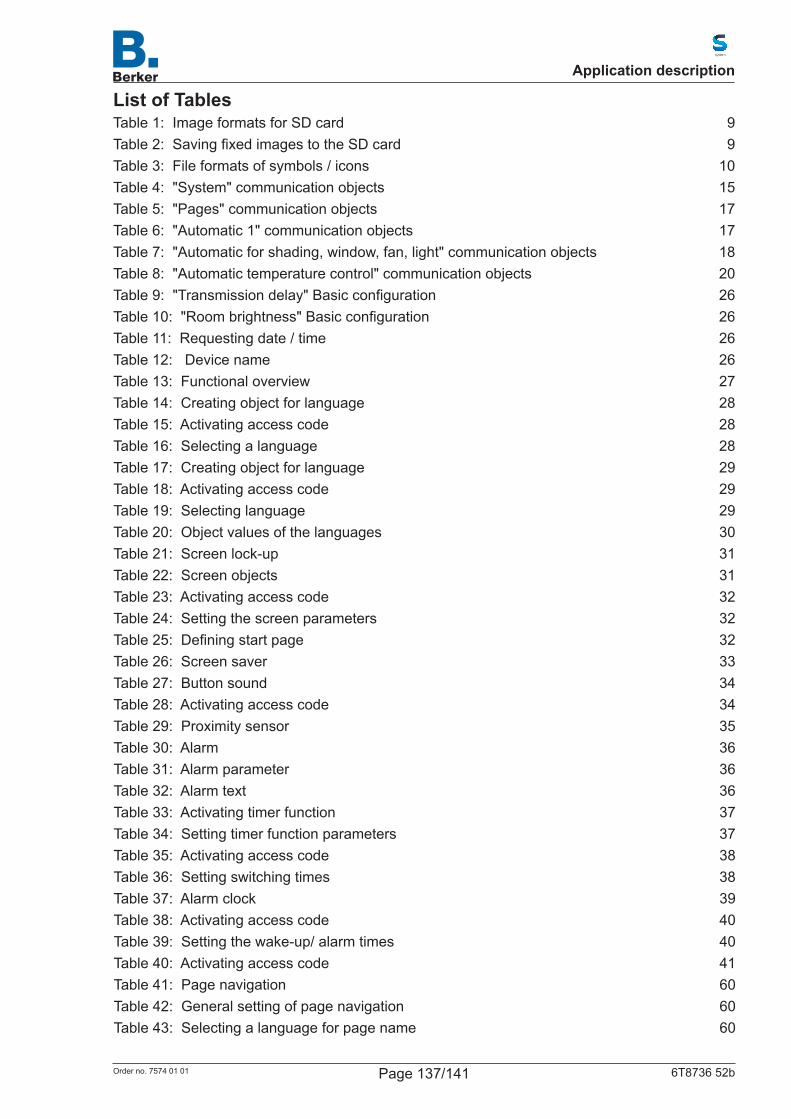
List of TablesTable 1: Image formats for SD card 9Table2: SavingfixedimagestotheSDcard 9Table 3: File formats of symbols / icons 10Table 4: "System" communication objects 15Table 5: "Pages" communication objects 17Table 6: "Automatic 1" communication objects 17Table 7: "Automatic for shading, window, fan, light" communication objects 18Table 8: "Automatic temperature control" communication objects 20Table9: "Transmissiondelay"Basicconfiguration 26Table10: "Roombrightness"Basicconfiguration 26Table11: Requestingdate/time 26Table 12: Device name 26Table 13: Functional overview 27Table 14: Creating object for language 28Table 15: Activating access code 28Table 16: Selecting a language 28Table 17: Creating object for language 29Table 18: Activating access code 29Table 19: Selecting language 29Table 20: Object values of the languages 30Table 21: Screen lock-up 31Table 22: Screen objects 31Table 23: Activating access code 32Table 24: Setting the screen parameters 32Table25: Definingstartpage 32Table 26: Screen saver 33Table 27: Button sound 34Table 28: Activating access code 34Table 29: Proximity sensor 35Table 30: Alarm 36Table 31: Alarm parameter 36Table 32: Alarm text 36Table 33: Activating timer function 37Table 34: Setting timer function parameters 37Table 35: Activating access code 38Table 36: Setting switching times 38Table 37: Alarm clock 39Table 38: Activating access code 40Table 39: Setting the wake-up/ alarm times 40Table 40: Activating access code 41Table 41: Page navigation 60Table 42: General setting of page navigation 60Table 43: Selecting a language for page name 60
Application description
Page 137/141Order no. 7574 01 01 6T8736 52b
Table 44: Selecting page type 60Table 45: Selecting surface symbol 62Table46: Configurationofrockersymbol 64Table47: Configurationofrotarycontrolsymbol 65Table48: Configurationoftemperaturevalues 66Table49: ConfigurationofRGBcontroller 66Table50: Configurationoffunction8-bitvalue(0…255%) 66Table51: Configurationoffunction8-bitvalue(0…100%) 66Table52: Configurationoffunction8-bitvalue(0…360%) 66Table53: Configurationoffunction16-bitvalue 67Table54: Configurationoffunction16-bitfloatingpoint 67Table55: Configurationoffunction32-bitcounter 67Table56: Configurationoffunction32-bitfloatingpoint 68Table57: Overviewofpredefinedsymbols 79Table 58: Activating/deactivating automatic function 81Table 59: Assigning function of the automatic(s) 81Table 60: Position of the sun function 81Table 61: Location input by "calculate" function 82Table 62: Location input by "via comm. objects" function 82Table63: Configurationofadditionaltimeparameters 83Table 64: Choosing the selection of wind and rain alarms 84Table65: Configurationofwindalarm 84Table66: Configurationoftwilightvalue 84Table 67: Setting extension delay for shading 84Table 68: Setting window opening restriction 85Table 69: Ventilation lock-up when cooling 85Table 70: Night-time re-cooling 85Table 71: Frost alarm 86Table 72: Heat protection 86Table 73: Automatic reset 86Table 74: Automatic light control 87Table 75: Lock-up object for automatic light control 87Table 76: Differing feedback value of automatic setpoint 87Table 77: Designation of automatic name 87Table 78: Switching light at twilight 87Table 79: Setting brightness value 88Table 80: Automatic reset 88Table 81: Lock-up object for automatic shading 89Table 82: Differing feedback value of automatic setpoint 89Table 83: Release / lock-up of alarm objects 89Table 84: Assigning name for automatic control 90Table 85: Selecting shading 90Table86: Brightness-dependentconfigurationofshading 91Table 87: Adjusting sun position tracking 91Table 88: Shading position 92
Application description
Page 138/141Order no. 7574 01 01 6T8736 52b
Table 89: Room temperature lock-up 92Table 90: Outside temperature lock-up 92Table 91: Parameter only "visible" for shading 93Table 92: Parameter "tracks the sun" 93Table 93: Heat protection 94Table 94: Blind movement time-dependent 94Table 95: Activating alarms 95Table 96: Automatic reset 95Table 97: Angle of the direction of the sun 95Table 98: Automatic window 96Table 99: Lock-up object for automatic window 96Table 100: Feedback value in case of deviation from automatic setpoint 96Table 101: Einstellungen für die Alarm-ObjekteSettings for alarm objects 97Table 102: Language selection of automatic name 98Table 103: Setting ventilation parameters 98Table 104: Close window in case of temperature difference 99Table 105: Night-time re-cooling 99Table 106: Outside temperature lock-up 99Table 107: Window time dependent opening/closure 99Table 108: Setting opening restriction 100Table109: Configurationofparameter"alarms" 100Table 110: Perform Automatic Reset 100Table 111: Setting lock-up object automatic 101Table 112: Feedback value in case of deviation from automatic setpoint 101Table 113: Naming automatic function 102Table 114: Setting ventilation parameters 102Table 115: Supply air lock-up parameter 103Table 116: Fan speed parameters 103Table 117: Setting timer functions for night-time re-cooling 103Table 118: Setting outside temperature lock-up 103Table 119: Setting timed ventilation parameters 103Table 120: Using ventilation lock-up 104Table 121: Setting automatic reset 104Table 122: Encoding HVAC objects 105Table 123: Operating mode changeover 105Table 124: Parameterization of operating mode 106Table 125: Setting valve position parameters 106Table 126: Setting status objects for operating mode 106Table 127: Settimg type of regulation 107Table 128: Parameterisation of general setpoint settings 107Table 129: Heating/cooling, change-over via object 107Table 130: Setting setpoint changes 107Table 131: Setting comfort extension 108Table 132: Setting setpoint "comfort" 108Table 133: Setting dead zone 108
Application description
Page 139/141Order no. 7574 01 01 6T8736 52b
Table 134: Setting setpoint "standby" 108Table 135: Setting setpoint reduction for heating/cooling 108Table 136: Setting setpoint "night reduction" 108Table 137: Setting setpoint reduction for heating/cooling 109Table 138: Setting setpoint "frost/heat protection" 109Table 139: Valve position "General" 110Table 140: Setting "heating control level" parameter 111Table 141: Setting "heating control level" valve position 111Table 142: Setting "supplementary heating" parameters 112Table 143: Setting hysteresis value 112Table 144: Valve position for lock-up 112Table 145: PI control parameters 113Table 146: Regulator lock-up for PI control 113Table147: PIcontrolwithpredefinedapplication: 113Table 148: Setting "cooling control level" parameter 114Table 149: Setting "cooling control level" valve position 114Table 150: Setting "supplementary cooling" parameter 115Table 151: Setting hysteresis value 115Table 152: Lock-up valve position 115Table 153: PI control "cooling" 116Table 154: Valve position for lock-up 116Table155: Controltypeforpredefinedapplication 116Table 156: Activating interfaces 117Table 157: Assignment of functions 117Table 158: Interface "Function as switch" 117Table 159: Interface "Function as toggle switch" 118Table 160: Interface "Function as blind switch" 118Table 161: Interface "Function as roller shutter switch" 119Table 162: Interface "Function as awning control" 120Table 163: Interface "Function as window control" 121Table 164: Table : Operating mode for standard controls 122Table 165: Behaviour when buttonpressedbrieflyandlong 122Table 166: Control mode "Extended" 122Table 167: Control mode "Function as dimmer" 123Table 168: Control mode "Function as 8-bit value transmitter" 123Table 169: Control mode "Function as 16-bit value transmitter" 123Table 170: Control mode "Function for scene control" 123Table 171: Control mode "Temperature sensor NTC" 124Table 172: Activating temperature limits 125Table 173: Preset temperature limit 125Table 174: Preset temperature limit via parameter 125Table 175: Preset threshold value via communication object 125Table 176: Setting "ON/OFF output" response 126Table 177: Lock-up of "ON/OFF output" 127
Application description
Page 140/141Order no. 7574 01 01 6T8736 52b
Table 178: Parameter for lock-up of the ON/OFF output 127Table 179: Parameter "Lock-up of output at temperature limit" when changing "ON/OFF output emission" 127Table 180: Selection of scene objects 128Table 181: Assigning parameters for scene object 128Table 182: Value assignment for scenes 129Table 183: Activating logic inputs 129Table 184: Activating AND logic gates 129Table 185: Activating OR logic gate 129Table 186: Setting options for the logic gates 130Table 187: Transmission behaviour with 1-bit object 130Table 188: Transmission behaviour with two 8-bit objects 130Table 189: Object value A if logic result = 1 130Table 190: Object value A if logic result = 0 130Table 191: Object value B with logic output =1 131Table 192: Object value B with logic output =0 131Table 193: Transmission behaviour of the logic gate 131Table194: Blockingbehaviourbeforefirstcommunication 131Table 195: Transmission behaviour of the logic outputs 132Table 196: Logic functions 133Table 197: Characteristics 134
Application description
Page 141/141Order no. 7574 01 01 6T8736 52b


![TUIC: Enabling Tangible Interaction on Capacitive Multi-touch … · 2018-05-05 · [6,22,24]. Capacitive multi-touch displays are thinner and lighter than ... The multi-touch controller](https://img.pdfslide.us/doc/110x75/5e8d9174d7de937981669a0c/tuic-enabling-tangible-interaction-on-capacitive-multi-touch-2018-05-05-62224.jpg)


![Pen + Touch = New Toolsiis-lab.org/paper/UIST2010_penplustouch.pdf · touch represent the future of displays [15,21], the presence of both modalities should significantly alter our](https://img.pdfslide.us/doc/110x75/5e83421c96853059a84ac81f/pen-touch-new-toolsiis-laborgpaperuist2010-touch-represent-the-future.jpg)