Embed Size (px)
DESCRIPTION
Not By ME
Citation preview
Pool Pilot ®
Digital Salt Chlorine Generator
By
Swimming Pool and Spa Purification System
Model # 75003
Owners Manual
(For Indoor or Outdoor Use)
IMPORTANT. Read This Manual Before Installing & Operating
This manual covers the installation of the Digital Chlorine Generator with any of the following Cell/Manifold assemblies (sold separately);
94105, 94107, 94113, 941-15C
This manual also covers the installation, connection and programming of the optional #75001 Pool Chemistry Controller for the Pool Pilot Digital Total Control,
and the #75004, 75005, 75006, or 75007 pH Acid Feed Pump and Tank Kit.
Pool Owner - Save this manual for reference. Installer - Leave this manual with pool owner.
IMPORTANT SAFETY INSTRUCTIONS
ii
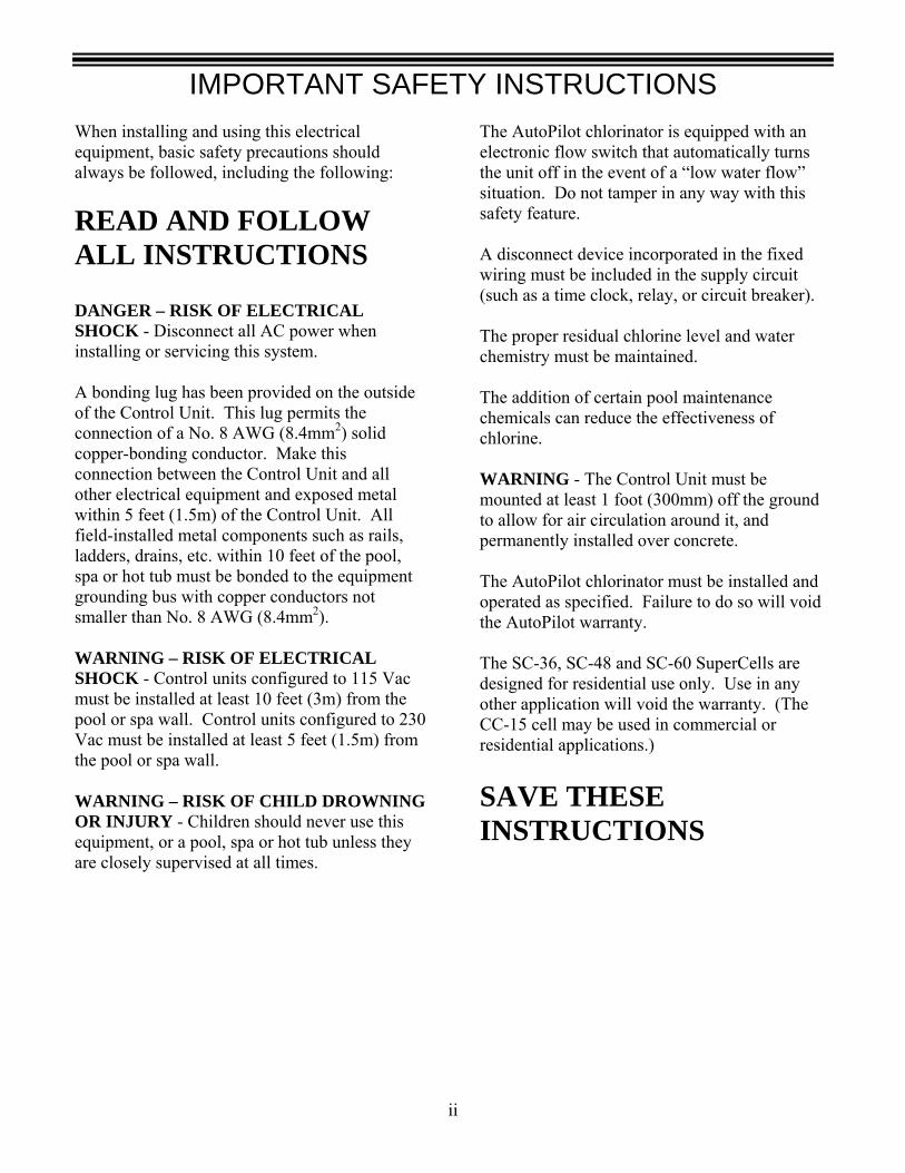
When installing and using this electrical equipment, basic safety precautions should always be followed, including the following:
READ AND FOLLOW ALL INSTRUCTIONS
DANGER – RISK OF ELECTRICAL SHOCK - Disconnect all AC power when installing or servicing this system. A bonding lug has been provided on the outside of the Control Unit. This lug permits the connection of a No. 8 AWG (8.4mm2) solid copper-bonding conductor. Make this connection between the Control Unit and all other electrical equipment and exposed metal within 5 feet (1.5m) of the Control Unit. All field-installed metal components such as rails, ladders, drains, etc. within 10 feet of the pool, spa or hot tub must be bonded to the equipment grounding bus with copper conductors not smaller than No. 8 AWG (8.4mm2). WARNING – RISK OF ELECTRICAL SHOCK - Control units configured to 115 Vac must be installed at least 10 feet (3m) from the pool or spa wall. Control units configured to 230 Vac must be installed at least 5 feet (1.5m) from the pool or spa wall. WARNING – RISK OF CHILD DROWNING OR INJURY - Children should never use this equipment, or a pool, spa or hot tub unless they are closely supervised at all times.
The AutoPilot chlorinator is equipped with an electronic flow switch that automatically turns the unit off in the event of a “low water flow” situation. Do not tamper in any way with this safety feature. A disconnect device incorporated in the fixed wiring must be included in the supply circuit (such as a time clock, relay, or circuit breaker). The proper residual chlorine level and water chemistry must be maintained. The addition of certain pool maintenance chemicals can reduce the effectiveness of chlorine. WARNING - The Control Unit must be mounted at least 1 foot (300mm) off the ground to allow for air circulation around it, and permanently installed over concrete. The AutoPilot chlorinator must be installed and operated as specified. Failure to do so will void the AutoPilot warranty. The SC-36, SC-48 and SC-60 SuperCells are designed for residential use only. Use in any other application will void the warranty. (The CC-15 cell may be used in commercial or residential applications.) SAVE THESE INSTRUCTIONS
UNIT NUMBERS AND CONTACT INFORMATION
iii
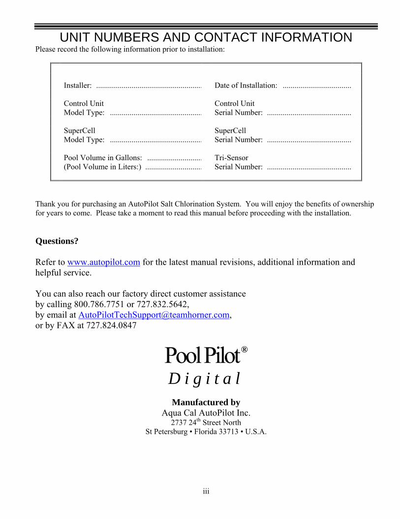
Please record the following information prior to installation:
Installer: ......................................................
Date of Installation: ...................................
Control Unit Model Type: ...............................................
Control Unit Serial Number: ...........................................
SuperCell Model Type: ...............................................
SuperCell Serial Number: ...........................................
Pool Volume in Gallons: ............................(Pool Volume in Liters:) .............................
Tri-Sensor Serial Number: ...........................................
Thank you for purchasing an AutoPilot Salt Chlorination System. You will enjoy the benefits of ownership for years to come. Please take a moment to read this manual before proceeding with the installation. Questions? Refer to www.autopilot.com for the latest manual revisions, additional information and helpful service. You can also reach our factory direct customer assistance by calling 800.786.7751 or 727.832.5642, by email at [email protected], or by FAX at 727.824.0847
Pool Pilot ® D i g i t a l
Manufactured by
Aqua Cal AutoPilot Inc. 2737 24th Street North
St Petersburg • Florida 33713 • U.S.A.

TABLE OF CONTENTS
iv
IMPORTANT SAFETY INSTRUCTIONS ..................................................................................................... ii UNIT NUMBERS / AUTOPILOT CONTACT INFO.................................................................................... iii TABLE OF CONTENTS........................................................................................................................... iv - vi
SYSTEM OVERVIEW .................................................................................................................................... 1 CHLORINE GENERATION ..................................................................................................................................................................1 PH CONTROL M ODE........................................................................................................................................................................2 TOTAL CONTROL MODE ..................................................................................................................................................................2 TOTAL CONTROL PROTECTION.................................................................................................................................................2 DEFINING ORP (ACTIVE CHLORINE) OPERATION...............................................................................................................2 DEFINING PH OPERATION..................................................................................................................................................2 CONTROL UNIT FEATURES................................................................................................................................. 3 PATENTED TEMPERATURE COMPENSATION .....................................................................................................................................3 PATENTED AUTOMATIC-FLOW BYPASS MANIFOLD ASSEMBLY.......................................................................................................3
SPECIFICATIONS........................................................................................................................................... 4 FOR #75003 POOL PILOT DIGITAL CONTROL UNIT AC INPUT POWER ............................................................................................................................................................................4 CHLORINE OUTPUT ..........................................................................................................................................................................4 MANIFOLD FLOW REQUIREMENTS ...................................................................................................................................................4 PUMP/AUXILIARY RELAY INPUT/OUTPUT........................................................................................................................................4 AGENCY APPROVALS.......................................................................................................................................................................4 FOR #75001 POOL CHEMISTRY CONTROLLER UNIT PH ACID FEED PUMP AND TANK AC INPUT POWER ........................................................................................................................4 Low Voltage Input Power ...............................................................................................................................................................4 Flow Cell.........................................................................................................................................................................................4
PREPARING THE POOL WATER................................................................................................................. 5 CALCULATING POOL VOLUME .........................................................................................................................................................5 TYPE OF SALT ..................................................................................................................................................................................5 HOW TO ADD SALT OR REMOVE SALT.............................................................................................................................................5 SALT LEVEL.....................................................................................................................................................................................5 SALT ADDITION CHART ..................................................................................................................................................................6 BASIC WATER CHEMISTRY ..............................................................................................................................................................7 SATURATION INDEX (SI) ..................................................................................................................................................................8
INSTALLATION ............................................................................................................................................. 9 BEFORE INSTALLING THE #75003 POOL PILOT DIGITAL SYSTEM ........................................................................................................9 WHAT IS INCLUDED..........................................................................................................................................................................9 WHAT IS NOT INCLUDED ..................................................................................................................................................................9 PLUMBING REQUIREMENTS............................................................................................................................................................10 ELECTRICAL REQUIREMENTS.........................................................................................................................................................10 INSTALLATION STEPS.....................................................................................................................................................................10 PLUMBING THE MANIFOLD ASSEMBLY ............................................................................................................ 11 MOUNTING THE #75003 DIGITAL CONTROL UNIT ........................................................................................... 12 ELECTRICAL CONNECTIONS ............................................................................................................................. 13 GROUNDING AND BONDING ............................................................................................................................. 13 HIGH VOLTAGE WIRING .................................................................................................................................. 13 CONVERTING FROM 230 VAC TO 115VAC ...................................................................................................................................13 CONNECTING POWER TO THE POOL PILOT .....................................................................................................................................14 CONNECTING POOL PILOT TO AN EXTERNAL TIMER OR CONTROLLER ..........................................................................................14 CONNECTING POOL PILOT TO ONE-SPEED PUMP OR ACID PUMP ......................................................................................................I CONNECTING POOL PILOT TO TWO-SPEED PUMP...........................................................................................................................14
TABLE OF CONTENTS
v
LOW VOLTAGE WIRING .................................................................................................................................... 15 CONNECTING THE SUPERCELL CABLE...........................................................................................................................................15 CONNECTING THE TRI-SENSOR CABLE ..........................................................................................................................................15
INSTALLATION – POOL CHEMISTRY CONTROLLER AND PH CONTROL SYSTEM..................... 16 BEFORE INSTALLING THE #75001 POOL PILOT POOL CHEMISTRY CONTROLLER SYSTEM ............................... 17 WHAT IS INCLUDED .......................................................................................................................................................................17 WHAT IS NOT INCLUDED ................................................................................................................................................................17
MOUNTING THE POOL CHEMISTRY CONTROLLER UNIT ................................................................ 18
POOL CHEMISTRY CONTROLLER SENSORS AND INTERFACE CABLE ......................................... 19 CONNECTING THE ORP AND PH CONNECTORS..............................................................................................................................19 CONNECTING THE INTERFACE CABLE ............................................................................................................................................19
PH INSTALLATION...................................................................................................................................... 20 CONNECTING THE PH FEED PUMP..................................................................................................................................................20 INTO THE DIGITAL CONTROL UNIT............................................................................................................................................20 INTO THE #75008 AUXILIARY RELAY KIT .................................................................................................................................20
POOL CHEMISTRY CONTROLLER FLOW CELL PLUMBING ............................................................. 21 pH CONTROL PLUMBING.......................................................................................................................... 22
CONNECTING THE #75003 DIGITAL TO ANY OTHER ORP CONTROLLER..................................... 23 INSTALLING THE OPTIONAL #110-ORP RELAY KIT...................................................................................................................23
CONNECTING THE #75003 DIGITAL TO AN ELECTRONIC CONTROLLER ..................................... 24
MENU OVERVIEW ...................................................................................................................................... 25
PROGRAMMING AND OPERATION......................................................................................................... 27 CONTROL PANEL FEATURES AND FUNCTIONS.................................................................................................. 26 CONTROL OPTIONS AND SYSTEM START UP...................................................................................................... 27 PURIFIER MODE - QUICK PROGRAMMING......................................................................................................................................27 PH CONTROL MODE - QUICK PROGRAMMING................................................................................................................................28 TOTAL CONTROL (TC) MODE - QUICK PROGRAMMING ................................................................................................................28 OPERATION OF BUTTONS ................................................................................................................................. 29 ADJUSTING THE PURIFIER OUTPUT % ............................................................................................................................................29 BOOST OR SUPERBOOST ................................................................................................................................................................29 MENU BUTTON ..............................................................................................................................................................................29 SELECT BUTTON ............................................................................................................................................................................29 PUMP BUTTON ...............................................................................................................................................................................30 TEST POOL PILOT PROGRAM............................................................................................................................ 31 VIEW SETUP PROGRAM.................................................................................................................................... 31 SELECT LANGUAGE PROGRAM......................................................................................................................... 32 SELECT UNITS PROGRAM................................................................................................................................. 32 SELECT TEMPERATURE PROGRAM ................................................................................................................... 32 SELECT 12/24 HOUR CLOCK PROGRAM ............................................................................................................ 32 SET TIME OF DAY PROGRAM ............................................................................................................................ 32 PROGRAMMING PUMP OPERATING TIMES........................................................................................................ 32 ACTIVATING FORCE REVERSE.......................................................................................................................... 33 PROGRAMMING REVERSE TIME ....................................................................................................................... 33 ENABLE / DISABLE REMOTE ............................................................................................................................ 33 REPLACE CELL (RESET AMPERE - HOUR COUNTER)......................................................................................... 33 SET PRIME PROTECT ........................................................................................................................................ 33

TABLE OF CONTENTS
vi
SALT CALIBRATION.......................................................................................................................................... 34 ADJUSTING TEMPERATURE DISPLAY ................................................................................................................. 34 PROGRAMMING POOL VOLUME ....................................................................................................................... 34 PROGRAMMING CELL TYPE ............................................................................................................................. 34 PROGRAMMING CELL POWER .......................................................................................................................... 34 PROGRAMMING SET RELAY 1 FUNCTION (PUMP CONTROL) ............................................................................ 34 PROGRAMMING SELECT REMOTE (ELECTRONIC CONTROLLER INTERFACE) .................................................... 35 PROGRAMMING SYSTEM MODE ....................................................................................................................... 35 PH CONTROL AND TOTAL CONTROL MENUS ................................................................................................... 35 BOOST ACID ..................................................................................................................................................................................35 PRIME ACID PUMP .........................................................................................................................................................................35 RESET ACID METER ........................................................................................................................................................................35 ENABLE / DISABLE ACID.................................................................................................................................................................35 TOTAL CONTROL MENUS................................................................................................................................. 36 SET PH OVERFEED .........................................................................................................................................................................36 SET PH MIN .....................................................................................................................................................................................36 SET PH MAX....................................................................................................................................................................................36 CALIBRATING PH ............................................................................................................................................................................36 ENABLE/DISABLE ORP...................................................................................................................................................................36 SET ORP OVERFEED.......................................................................................................................................................................36 ELECTRONIC CONTROLLER OPERATION........................................................................................................... 37 ADJUSTING AND SUPERCHLORINATING THE POOL PILOT THROUGH THE ELECTRONIC CONTROLLER CONTROL PANEL..................37 PROGRAMMING THE POOL PILOT DIGITAL FOR AN ELECTRONIC CONTROLLER .............................................................................37 ELECTRONIC CONTROLLER DISPLAYS “CHECK POOL PILOT”...................................................................................................37
SYSTEM MAINTENANCE .......................................................................................................................... 38 WINTERIZING.................................................................................................................................................................................38 FREEZE PROTECTION PROGRAM ....................................................................................................................................................38 SPRING START-UP..........................................................................................................................................................................38 FUSE LOCATIONS AND RATINGS ....................................................................................................................................................39 TRI-SENSOR ASSEMBLY................................................................................................................................... 40 REMOVING/INSPECTING/CLEANING THE TRI-SENSOR.....................................................................................................................40 TESTING THE FLOW SWITCH, CLEANING THE FILTER SCREEN, AND CLEANING THE BYPASS VALVE ............................................41 SUPERCELL...................................................................................................................................................... 41 REMOVAL OF THE SUPERCELL.......................................................................................................................................................41 VISUAL INSPECTION OF THE SUPERCELL .......................................................................................................................................42 MANUAL CLEANING OF THE SUPERCELL.......................................................................................................................................42 INSTALLATION OF THE SUPERCELL................................................................................................................................................42
POOL CHEMISTRY CONTROL MAINTENANCE AND CLEANING..................................................... 43 HELPFUL HINTS .............................................................................................................................................................................43 REMOVAL ......................................................................................................................................................................................43 CLEANING......................................................................................................................................................................................43 TESTING THE FLOW CELL ..............................................................................................................................................................43
TROUBLESHOOTING GUIDE ............................................................................................................. 44 - 49 STANDARD DISPLAYS ............................................................................................................................................................ 44 - 47 OTHER CONDITIONS.......................................................................................................................................................................47 TOTAL CONTROL AND PH DISPLAYS ..................................................................................................................................... 48 - 49
SYSTEM OVERVIEW
1
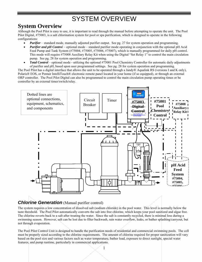
System Overview Although the Pool Pilot is easy to use, it is important to read through the manual before attempting to operate the unit. The Pool Pilot Digital, #75003, is a salt chlorination system for pool or spa purification, which is designed to operate in the following configurations:
• Purifier – standard mode, manually adjusted purifier output. See pg. 27 for system operation and programming. • Purifier and pH Control – optional mode – standard purifier mode operating in conjunction with the optional pH Acid
Feed Pump and Tank System (#75004, #75005, #75006, #75007), which is manually programmed for daily pH control. This mode will require #75008 Auxiliary Relay Kit when using the Digital “Set Relay 1” to control the main circulation pump. See pg. 28 for system operation and programming.
• Total Control – optional mode - utilizing the optional #75001 Pool Chemistry Controller for automatic daily adjustments of purifier and pH, based upon user programmed settings. See pg. 28 for system operation and programming.
The Pool Pilot has a digital interface that allows the unit to be operated through a Jandy® Aqualink RS (versions I and K only), Polaris® EOS, or Pentair IntelliTouch® electronic remote panel located in your home (if so equipped), or through an external ORP controller. The Pool Pilot Digital can also be programmed to control the main circulation pump operating times or be controller by an external timer/switch/relay.
Chlorine Generation (Manual purifier control) The system requires a low concentration of dissolved salt (sodium chloride) in the pool water. This level is normally below the taste threshold. The Pool Pilot automatically converts the salt into free chlorine, which keeps your pool sanitized and algae free. The chlorine reverts back to a salt after treating the water. Since the salt is constantly recycled, there is minimal loss during a swimming season. However, salt can be lost due to filter backwash, rain water overflow, leaks, or bather splashing/carryout, but not through evaporation. The Pool Pilot Control Unit is designed to handle the purification needs of residential and commercial swimming pools. The cell must be properly sized according to the chlorine requirements. The amount of chlorine required for proper sanitization will vary based on the pool size and various factors such as water temperature, bather load, exposure to direct sunlight, special water features, and pump runtime, particularly in commercial applications.
Electronic Controller
System Dotted lines are
optional connection
schematics and components.
pH Acid Feed
System #75004, #75005, #75006
#75008 Auxiliary Relay Kit
Dotted lines are optional connections, equipment, schematics, and components
#75001 Pool
Chemistry Control
Circuit Breaker
Timer
AUTOPILOT SYSTEMS INC
#75003 Digital Control

SYSTEM OVERVIEW
2
pH Control Mode (Manual purifier and pH control) Note: Requires option # 75004, 75005, 75006, or 75007 pH Acid Feed Pump and Tank System must be installed with the #75003 Digital Controller for this mode to function. Option # 75008 Auxiliary Relay Kit will be necessary if the Digital is used to control the main circulation pump. This mode adds to the Purifier mode by using an Acid feed pump that is user programmed for manual feed of diluted muriatic acid. The Acid Feed Pump and Tank System come with Autopilot and Stenner factory components. If the Stenner factory components are used for the installation, follow their installation instructions. Otherwise, follow the instructions in this manual.
Total Control Mode - Pool Chemistry Controller (Automated purifier and pH control) Note: Option #75001 Pool Chemistry Controller and the pH Control System must both be installed with the #75003 Digital Controller for this mode to function. These options activate the Total Control mode in which the purifier (ORP – defined below) and pH levels are monitored (using sensors) and controlled automatically, to maintain proper levels. The system automatically enters the Total Control configuration if it is able to communicate with the Pool Chemistry Controller. The system will display "Error purify off, Error acid off, Check OpEC" if it is not able to communicate with the Pool Chemistry Controller. OpEC is the acronym for “ORP pH Electronic Controller” and is the electronic control logic of the Pool Chemistry Controller. Under normal operating mode, the Total Control display cycles between the “ORP” screen, the “pH” screen, and the “Salt level” screen.
Total Control Protection The Total Control system does not generate chlorine or dispense acid if:
• A one-speed or two speed pump is not running, • Flow (at the Manifold Tri-sensor or Flow Cell flow switch) is not detected, • Salt is below 2000 ppm, • Communications with the #75001 Pool Chemistry Controller is lost, • A sensor error is detected, • An overfeed condition is detected (if set to detect pH or ORP overfeed), • An extended period of high pH condition is detected.
Also: • The Total Control system does not dispense acid until after flow has been detected a minimum of three (3) minutes
after activation. • The Total Control system does not generate chlorine or dispense acid one (1) minute prior to the Pump Program “Off”
time, when programmed for a One speed pump.
ORP (Oxidation Reduction Potential - measured in millivolts, mV) ORP is a measurement of the amount of active oxidizer (chlorine) in the water. This system controls ORP by generating chlorine when the ORP measurement falls below a user programmable set point, which should correspond with the desired free chlorine level. A one-minute timer prevents the chlorine generation circuit from cycling on/off unless an error condition exists. The first line of the ORP screen displays the measured ORP, followed by the ORP set point in parenthesis (as shown below). The ORP screen contains the text “On” only if chlorine is being generated. The ORP display range is 200 to 900mV. The second line of the ORP screen indicates if the ORP is high or low, relative to the set point. If the measured ORP is equal to the set point, a block █ with no text is displayed. If the measurement falls below the set point, the ▼ and Low are displayed and chlorine is generated. If the measurement exceeds the set point, the ▲ and High are displayed and no chlorine is generated.
pH The system controls pH by dispensing diluted mixture of water and muriatic acid (4:1 ratio recommended) when the pH rises above a user programmable set point, which should correspond with the desired pH level. To avoid overdosing, the system dispenses acid in low increments based on the difference between the set point and the measured pH. The first line of the pH screen displays the measured pH, followed by the pH set point in parenthesis (as shown below). The pH screen contains the text “On” only if acid is being dispensed. The pH display range is 4.00 to 9.90. The second line of the pH screen indicates if the pH is high or low, relative to the set point. If the measured pH is equal to the set point, a block █ with no text is displayed. If the measurement falls below the set point, the ▼ and Low are displayed and no acid is fed. If the measurement exceeds the set point, the ▲ and High are displayed and acid is fed until set point is reached.
pH 4.00(7.50) █▼▼▼▼▼▼▼ Low
pH 7.50(7.50) █
pH 9.90(7.50) On High ▲▲▲▲▲▲▲▲█
ORP 200(650)On. █▼▼▼▼▼▼▼ Low
ORP 650(650) █
ORP 900(650) High ▲▲▲▲▲▲▲▲█
SYSTEM OVERVIEW
3
Control Unit Features The control unit has the following features:
• Patented temperature compensation for chlorine output • Programmable Microprocessor Control • Multi-language digital display – (English, Spanish, French & German) • Digitally controlled power to the SuperCell • Tri-sensor Circuitry to monitor water flow, water temperature, and salt level (and salt addition amounts to maintain 3000 ppm (3.0 g/l)) • Internal Relay for controlling an external pump or acid feeder • On-board Diagnostic and Test programs • Lithium battery (CR-2025) back up for clock and program settings • ORP dry contact interface for connection to an external ORP controller. • Electronic controller interface for Jandy® (Versions I, K, and newer), Polaris® EOS, or Pentair IntelliTouch® controllers.
Patented Temperature Compensation The Tri-Sensor Assembly’s temperature sensor works in conjunction with the purifier % output to automatically adjust the chlorine output based upon changes in the water temperature between the range of 55°F – 95°F (13°C - 35°C). As temperatures fall lower than 75°F (24°C), the unit will activate a high purifier % lock out and may not allow purifier adjustments up to 100%. This prevents the unit from overdriving the cell under cold temperatures, which can cause premature cell wear. At 55°F (13°C) or colder, the unit will adjust to a fixed 1% output to prevent the over chlorination and premature cell failure during cooler temperatures. At 95°F (35°C) or warmer, the unit will adjust up to 100% of the normal purifier % setting to prevent under chlorination during warmer temperatures. The Temperature Compensation feature is not needed and is therefore automatically disabled when the Pool Pilot Digital (model #75003) is installed as a part of the Digital TC Total Control System (in conjunction with Autopilot’s Pool Chemistry Controller - # 75001)
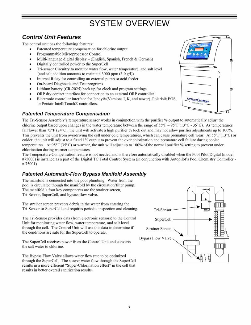
Patented Automatic-Flow Bypass Manifold Assembly The manifold is connected into the pool plumbing. Water from the pool is circulated though the manifold by the circulation/filter pump. The manifold’s four key components are the strainer screen, Tri-Sensor, SuperCell, and bypass flow valve. The strainer screen prevents debris in the water from entering the Tri-Sensor or SuperCell and requires periodic inspection and cleaning. The Tri-Sensor provides data (from electronic sensors) to the Control Unit for monitoring water flow, water temperature, and salt level through the cell. The Control Unit will use this data to determine if the conditions are safe for the SuperCell to operate. The SuperCell receives power from the Control Unit and converts the salt water to chlorine. The Bypass Flow Valve allows water flow rate to be optimized through the SuperCell. The slower water flow through the SuperCell results in a more efficient “Super-Chlorination effect” in the cell that results in better overall sanitization results.
Tri-Sensor
SuperCell
Strainer Screen
Bypass Flow Valve
CHECK SYSTEM
BOOST MENU SELECT PUMP
SPECIFICATIONS
4
Specifications #75003 Pool Pilot Digital Control unit
Input Power 230 Vac 1.5 amps (Normal input configuration shipped from the factory) 115 Vac 3 amps (Optional input configuration – jumper wire to convert included) Dry Contact 5 mA typical Non-factory ORP input circuit (110Vac output require a Relay Kit – PN# 110-ORP)
Chlorine Output SuperCell Type Maximum Chlorine Output (# 75003 Control unit set on Cell Power 3)
SC-36 1.28 lbs/day (0.58 kg/day) SC-48 1.56 lbs/day (0.71 kg/day) SC-60 1.92 lbs/day (0.88 kg/day) CC-15 2.50 lbs/day (1.14 kg/day) – Commercial Cell
Manifold Flow Requirements Minimum Flow Rate 20 gallons per minute (gpm) (76 liters/minute (L/m)) Maximum Flow Rate 100 gallons per minute (gpm) (379 liters/minute (L/m)) Maximum Pressure 85 psi (as tested by NSF)
Pump/Auxiliary Relay Output Voltage Input Amps / HP max 115 Vac 30 amps / 1 HP 230 Vac 30 amps / 2.5 HP
Agency Approvals • ETL tested to conform to the following UL specifications:
o UL1081 - Standard for Safety for Swimming Pool Pumps, Filters and Chlorinators • CAN/CSA-E335-1 - Safety of Household and Similar Electrical Appliances
#75001 Pool Pilot Pool Chemistry Control unit
pH Acid Feed Pump and Tank AC Input Power #75004 120 Vac 1.7 amps #75005 220 Vac 0.9 amps #75006 230 Vac 0.9 amps #75007 250 Vac 0.9 amps #75008 Auxiliary Relay Kit 115 / 230 Vac Relay 30 amps max
Low Voltage Input Power PCC Communication Factory Low Voltage Interface Cable provided with #75001 #75008 pH Auxiliary Relay Kit (Optional) Dedicated Factory Low Voltage Terminal
Flow Cell Flow Sensor Fail – Safe status Maximum working pressure 50 psi

PREPARING THE POOL WATER
5
Calculating Pool Volume (needed to determine proper balance chemical additions)
( )2
end shallow ofdepth end deep ofdepth Depth Average +=
Pool Shape Gallons (pool size measured in feet) Liters (pool size measured in meters) Rectangular Length x Width x Average Depth x 7.5 Length x Width x Average Depth x 1000 Round Diameter x Diameter x Average Depth x 5.9 Diameter x Diameter x Average Depth x 785 Oval Length x Width x Average Depth x 5.9 Length x Width x Average Depth x 785 Your calculated pool volume is ____________. Enter this number for reference on the information section, pg. iii.
Type of Salt It is important to use Sodium Chloride (NaCl) salt that is greater than 99% pure. Common types of salt include granular food grade, water softener pellets, or solar salt flakes. These are usually available in 25 lb to 80 lb bags at a local pool or building supply store. Water softener and solar salt will have a slower dissolve rate than food grade salt. Rock salt and Granular Salt with Iodine or Rust Preventatives should not be used as they contain high levels of impurities that will cause staining. Note: Granular salt with anti-caking additives such as YPS (Yellow Prussiate of Soda) or Sodium Ferrocyanide can be used but may cause a localized tint to the water or yellow staining on the pool finish if not mixed and dissolved immediately.
How to Add or Remove Salt The filter pump should be turned on and run continuously for 24 hours after salt is added to the pool to allow for proper dissolving and circulation throughout the pool. The filter pump should be run continually for up to 24 hours. The salt should be added directly to the pool and over the bottom main drain if so equipped. If there is no main drain, a vacuum head can be used to circulate the salt. Vacuum the salt, brush it around to agitate, or brush into the main drain (if applicable) to speed up the dissolving process. Caution: Do not use a pool cleaner or vacuum head with wheels as they can leave track marks on newly plastered pools. Do not allow Granular salt to pile up in one location without brushing as staining may occur. If the salt level in the pool becomes undesirably high, the only way to remove excess salt is to partially drain the pool and refill with fresh water.
Salt Level Your Pool Pilot requires that the size of your pool be entered into the microprocessor so that it can automatically measure the amount of salt in your pool and indicate how many pounds (kgs) to add when the salt level falls low. To program your pool size, see “Set Pool Volume” on pg. 34. To calculate the number of gallons (liters) of water in your pool, see Calculating Pool Volume above. The salt chart on the following page can also be used to calculate how much salt, in pounds (kgs) should be added to reach the recommended level of 3000 ppm (3.0 g/l). The ideal salt range is 2500 – 3500 PPM (parts per million) (2.5 – 3.5 g/l). However, the Pool Pilot can operate with salt levels in excess of 35,000 PPM (35.0 g/l), if so desired. High salt levels above 6000 PPM are not normally recommended as this may cause corrosion to metallic objects such as light fixtures, ladders, handrails, heaters, and pumps. Low salt levels below 2400ppm will reduce the efficiency of the Pool Pilot and result in low chlorine production. Extremely low salt levels below 1900 ppm will activate the low salt safety cut-off and halt chlorine production until salt is replenished to proper salt levels. The salt is constantly recycled during normal operation. The loss of salt during a swimming season should be minimal. Filter backwashing, draining due to rain water overflow, splashing and bathing suit drag out, and leaks (excessive salt loss in a short span of time) are typical ways the salt is lost. Salt does not evaporate from the pool when the water evaporates.
PREPARING THE POOL WATER
6
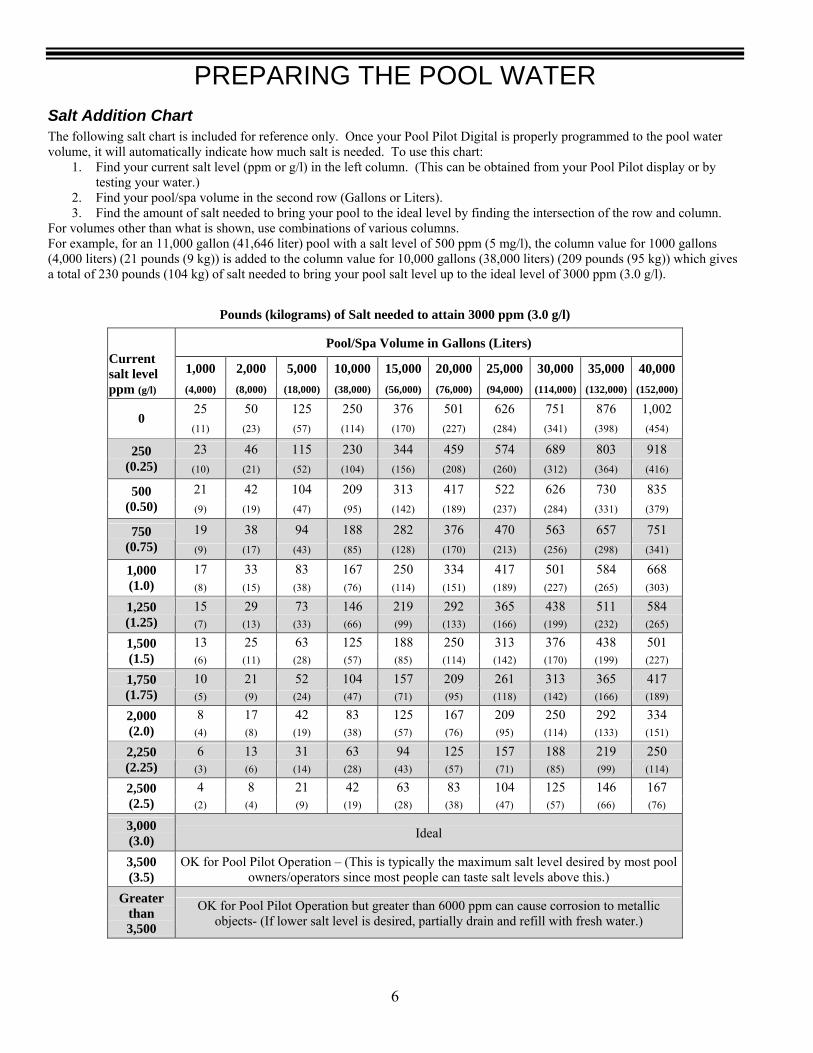
Salt Addition Chart The following salt chart is included for reference only. Once your Pool Pilot Digital is properly programmed to the pool water volume, it will automatically indicate how much salt is needed. To use this chart:
1. Find your current salt level (ppm or g/l) in the left column. (This can be obtained from your Pool Pilot display or by testing your water.)
2. Find your pool/spa volume in the second row (Gallons or Liters). 3. Find the amount of salt needed to bring your pool to the ideal level by finding the intersection of the row and column.
For volumes other than what is shown, use combinations of various columns. For example, for an 11,000 gallon (41,646 liter) pool with a salt level of 500 ppm (5 mg/l), the column value for 1000 gallons (4,000 liters) (21 pounds (9 kg)) is added to the column value for 10,000 gallons (38,000 liters) (209 pounds (95 kg)) which gives a total of 230 pounds (104 kg) of salt needed to bring your pool salt level up to the ideal level of 3000 ppm (3.0 g/l).
Pounds (kilograms) of Salt needed to attain 3000 ppm (3.0 g/l)
Pool/Spa Volume in Gallons (Liters)
1,000 2,000 5,000 10,000 15,000 20,000 25,000 30,000 35,000 40,000 Current salt level ppm (g/l) (4,000) (8,000) (18,000) (38,000) (56,000) (76,000) (94,000) (114,000) (132,000) (152,000)
25 50 125 250 376 501 626 751 876 1,002 0
(11) (23) (57) (114) (170) (227) (284) (341) (398) (454)
23 46 115 230 344 459 574 689 803 918 250 (0.25) (10) (21) (52) (104) (156) (208) (260) (312) (364) (416)
21 42 104 209 313 417 522 626 730 835 500 (0.50) (9) (19) (47) (95) (142) (189) (237) (284) (331) (379)
19 38 94 188 282 376 470 563 657 751 750 (0.75) (9) (17) (43) (85) (128) (170) (213) (256) (298) (341)
17 33 83 167 250 334 417 501 584 668 1,000 (1.0) (8) (15) (38) (76) (114) (151) (189) (227) (265) (303)
15 29 73 146 219 292 365 438 511 584 1,250 (1.25) (7) (13) (33) (66) (99) (133) (166) (199) (232) (265)
13 25 63 125 188 250 313 376 438 501 1,500 (1.5) (6) (11) (28) (57) (85) (114) (142) (170) (199) (227)
10 21 52 104 157 209 261 313 365 417 1,750 (1.75) (5) (9) (24) (47) (71) (95) (118) (142) (166) (189)
8 17 42 83 125 167 209 250 292 334 2,000 (2.0) (4) (8) (19) (38) (57) (76) (95) (114) (133) (151)
6 13 31 63 94 125 157 188 219 250 2,250 (2.25) (3) (6) (14) (28) (43) (57) (71) (85) (99) (114)
4 8 21 42 63 83 104 125 146 167 2,500 (2.5) (2) (4) (9) (19) (28) (38) (47) (57) (66) (76)
3,000 (3.0) Ideal
3,500 (3.5)
OK for Pool Pilot Operation – (This is typically the maximum salt level desired by most pool owners/operators since most people can taste salt levels above this.)
Greater than 3,500
OK for Pool Pilot Operation but greater than 6000 ppm can cause corrosion to metallic objects- (If lower salt level is desired, partially drain and refill with fresh water.)
PREPARING THE POOL WATER
7
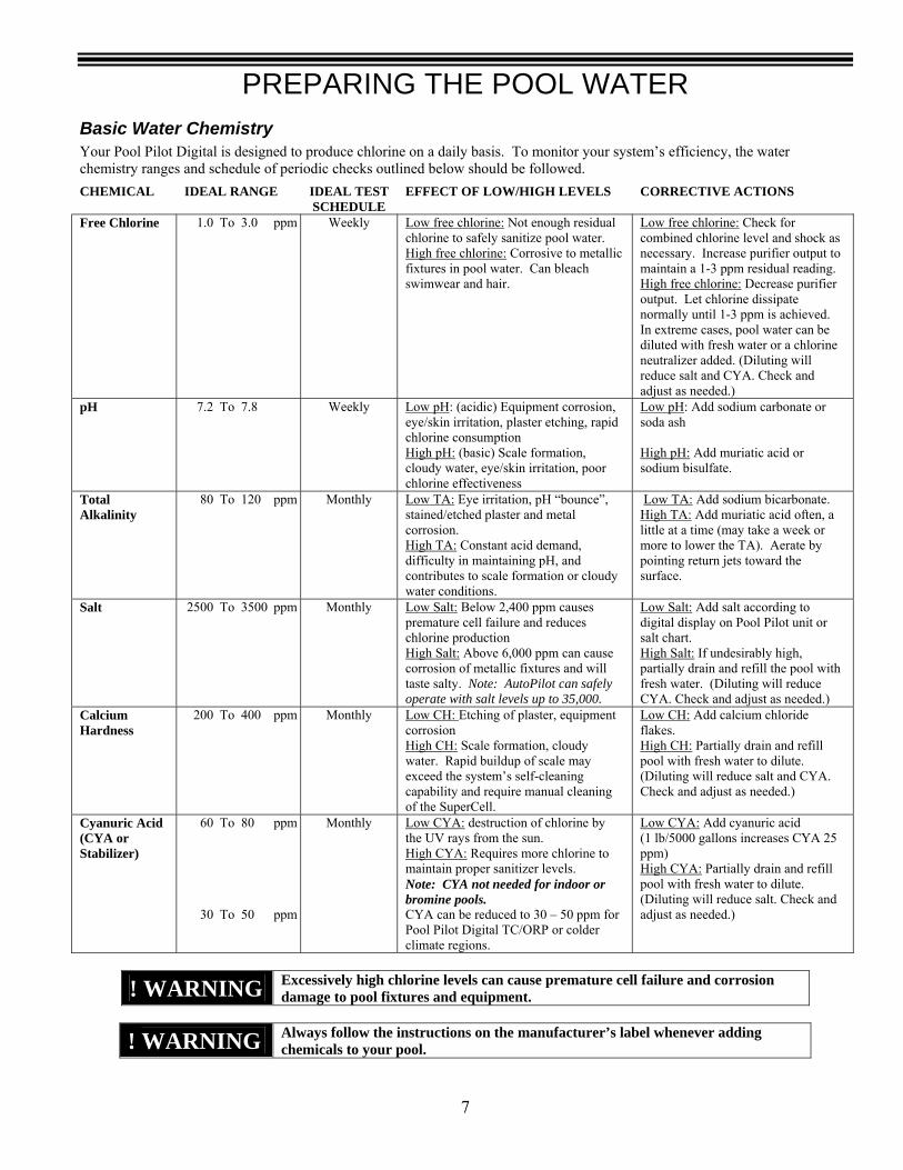
Basic Water Chemistry Your Pool Pilot Digital is designed to produce chlorine on a daily basis. To monitor your system’s efficiency, the water chemistry ranges and schedule of periodic checks outlined below should be followed.
CHEMICAL IDEAL RANGE IDEAL TEST SCHEDULE
EFFECT OF LOW/HIGH LEVELS CORRECTIVE ACTIONS
Free Chlorine 1.0 To 3.0 ppm Weekly Low free chlorine: Not enough residual chlorine to safely sanitize pool water. High free chlorine: Corrosive to metallic fixtures in pool water. Can bleach swimwear and hair.
Low free chlorine: Check for combined chlorine level and shock as necessary. Increase purifier output to maintain a 1-3 ppm residual reading. High free chlorine: Decrease purifier output. Let chlorine dissipate normally until 1-3 ppm is achieved. In extreme cases, pool water can be diluted with fresh water or a chlorine neutralizer added. (Diluting will reduce salt and CYA. Check and adjust as needed.)
pH 7.2 To 7.8 Weekly Low pH: (acidic) Equipment corrosion, eye/skin irritation, plaster etching, rapid chlorine consumption High pH: (basic) Scale formation, cloudy water, eye/skin irritation, poor chlorine effectiveness
Low pH: Add sodium carbonate or soda ash High pH: Add muriatic acid or sodium bisulfate.
Total Alkalinity
80 To 120 ppm Monthly Low TA: Eye irritation, pH “bounce”, stained/etched plaster and metal corrosion. High TA: Constant acid demand, difficulty in maintaining pH, and contributes to scale formation or cloudy water conditions.
Low TA: Add sodium bicarbonate. High TA: Add muriatic acid often, a little at a time (may take a week or more to lower the TA). Aerate by pointing return jets toward the surface.
Salt 2500 To 3500 ppm Monthly Low Salt: Below 2,400 ppm causes premature cell failure and reduces chlorine production High Salt: Above 6,000 ppm can cause corrosion of metallic fixtures and will taste salty. Note: AutoPilot can safely operate with salt levels up to 35,000.
Low Salt: Add salt according to digital display on Pool Pilot unit or salt chart. High Salt: If undesirably high, partially drain and refill the pool with fresh water. (Diluting will reduce CYA. Check and adjust as needed.)
Calcium Hardness
200 To 400 ppm Monthly Low CH: Etching of plaster, equipment corrosion High CH: Scale formation, cloudy water. Rapid buildup of scale may exceed the system’s self-cleaning capability and require manual cleaning of the SuperCell.
Low CH: Add calcium chloride flakes. High CH: Partially drain and refill pool with fresh water to dilute. (Diluting will reduce salt and CYA. Check and adjust as needed.)
Cyanuric Acid (CYA or Stabilizer)
60
30
To
To
80 50
ppm ppm
Monthly Low CYA: destruction of chlorine by the UV rays from the sun. High CYA: Requires more chlorine to maintain proper sanitizer levels. Note: CYA not needed for indoor or bromine pools. CYA can be reduced to 30 – 50 ppm for Pool Pilot Digital TC/ORP or colder climate regions.
Low CYA: Add cyanuric acid (1 lb/5000 gallons increases CYA 25 ppm) High CYA: Partially drain and refill pool with fresh water to dilute. (Diluting will reduce salt. Check and adjust as needed.)
! WARNING Excessively high chlorine levels can cause premature cell failure and corrosion damage to pool fixtures and equipment.
! WARNING Always follow the instructions on the manufacturer’s label whenever adding chemicals to your pool.
PREPARING THE POOL WATER
8
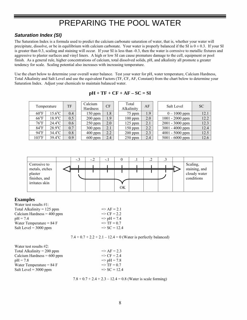
Saturation Index (SI) The Saturation Index is a formula used to predict the calcium carbonate saturation of water, that is, whether your water will precipitate, dissolve, or be in equilibrium with calcium carbonate. Your water is properly balanced if the SI is 0 ± 0.3. If your SI is greater than 0.3, scaling and staining will occur. If your SI is less than -0.3, then the water is corrosive to metallic fixtures and aggressive to plaster surfaces and vinyl liners. A high or low SI can cause premature damage to the cell, equipment or pool finish. As a general rule, higher concentrations of calcium, total dissolved solids, pH, and alkalinity all promote a greater tendency for scale. Scaling potential also increases with increasing temperature. Use the chart below to determine your overall water balance. Test your water for pH, water temperature, Calcium Hardness, Total Alkalinity and Salt Level and use the equivalent Factors (TF, CF, AF, Constant) from the chart below to determine your Saturation Index. Adjust your chemicals to maintain balanced water.
pH + TF + CF + AF – SC = SI
Temperature TF Calcium Hardness CF Total
Alkalinity AF Salt Level SC
60oF 15.6oC 0.4 150 ppm 1.8 75 ppm 1.9 0 – 1000 ppm 12.1 66oF 18.9oC 0.5 200 ppm 1.9 100 ppm 2.0 1001 - 2000 ppm 12.2 76oF 24.4oC 0.6 250 ppm 2.0 125 ppm 2.1 2001 - 3000 ppm 12.3 84oF 28.9oC 0.7 300 ppm 2.1 150 ppm 2.2 3001 - 4000 ppm 12.4 94oF 34.4oC 0.8 400 ppm 2.2 200 ppm 2.3 4001 - 5000 ppm 12.5
103oF 39.4oC 0.9 600 ppm 2.4 250 ppm 2.4 5001 - 6000 ppm 12.6
-.3 -.2 -.1 0 .1 .2 .3 Corrosive to metals, etches plaster finishes, and irritates skin
OK
Scaling, staining, and cloudy water conditions
Examples Water test results #1: Total Alkalinity = 125 ppm => AF = 2.1 Calcium Hardness = 400 ppm => CF = 2.2 pH = 7.4 => pH = 7.4 Water Temperature = 84 F => TF = 0.7 Salt Level = 3000 ppm => SC = 12.4
7.4 + 0.7 + 2.2 + 2.1 – 12.4 = 0 (Water is perfectly balanced)
Water test results #2: Total Alkalinity = 200 ppm => AF = 2.3 Calcium Hardness = 600 ppm => CF = 2.4 pH = 7.8 => pH = 7.8 Water Temperature = 84 F => TF = 0.7 Salt Level = 3000 ppm => SC = 12.4
7.8 + 0.7 + 2.4 + 2.3 – 12.4 = 0.8 (Water is scale forming)
INSTALLATION
9
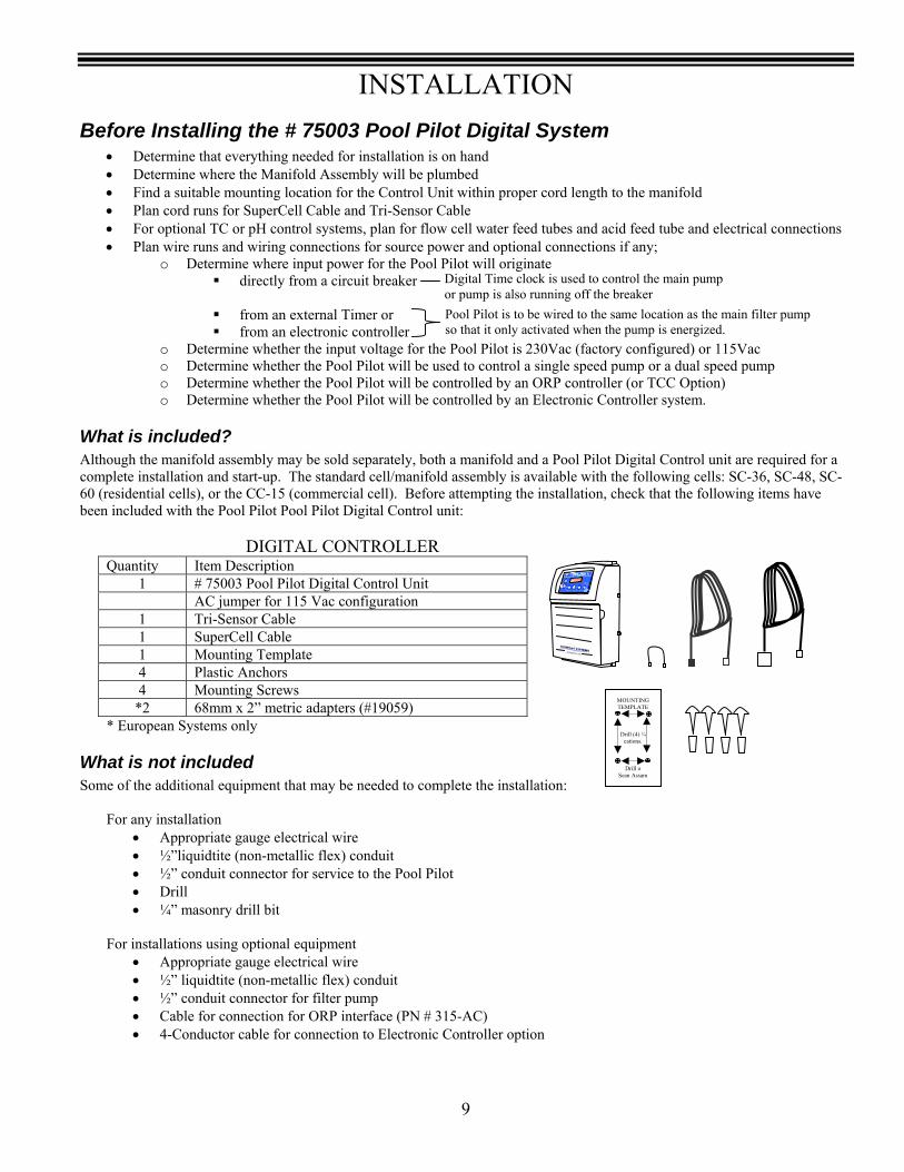
Before Installing the # 75003 Pool Pilot Digital System • Determine that everything needed for installation is on hand • Determine where the Manifold Assembly will be plumbed • Find a suitable mounting location for the Control Unit within proper cord length to the manifold • Plan cord runs for SuperCell Cable and Tri-Sensor Cable • For optional TC or pH control systems, plan for flow cell water feed tubes and acid feed tube and electrical connections • Plan wire runs and wiring connections for source power and optional connections if any;
o Determine where input power for the Pool Pilot will originate directly from a circuit breaker
from an external Timer or from an electronic controller
o Determine whether the input voltage for the Pool Pilot is 230Vac (factory configured) or 115Vac o Determine whether the Pool Pilot will be used to control a single speed pump or a dual speed pump o Determine whether the Pool Pilot will be controlled by an ORP controller (or TCC Option) o Determine whether the Pool Pilot will be controlled by an Electronic Controller system.
What is included? Although the manifold assembly may be sold separately, both a manifold and a Pool Pilot Digital Control unit are required for a complete installation and start-up. The standard cell/manifold assembly is available with the following cells: SC-36, SC-48, SC-60 (residential cells), or the CC-15 (commercial cell). Before attempting the installation, check that the following items have been included with the Pool Pilot Pool Pilot Digital Control unit: DIGITAL CONTROLLER
Quantity Item Description 1 # 75003 Pool Pilot Digital Control Unit AC jumper for 115 Vac configuration
1 Tri-Sensor Cable 1 SuperCell Cable 1 Mounting Template 4 Plastic Anchors 4 Mounting Screws
*2 68mm x 2” metric adapters (#19059) * European Systems only
What is not included Some of the additional equipment that may be needed to complete the installation:
For any installation
• Appropriate gauge electrical wire • ½”liquidtite (non-metallic flex) conduit • ½” conduit connector for service to the Pool Pilot • Drill • ¼” masonry drill bit
For installations using optional equipment
• Appropriate gauge electrical wire • ½” liquidtite (non-metallic flex) conduit • ½” conduit connector for filter pump • Cable for connection for ORP interface (PN # 315-AC) • 4-Conductor cable for connection to Electronic Controller option
Pool Pilot is to be wired to the same location as the main filter pump so that it only activated when the pump is energized.
Digital Time clock is used to control the main pump or pump is also running off the breaker
CHECKSYSTE
M
BOOST MENU SELECT PUMP
MOUNTING TEMPLATE
Drill (4) ¼ cations.
Drill o Sean Assam
INSTALLATION
10
Plumbing Requirements The Manifold Assembly is 2” Schedule 40 and is typically plumbed into the pool return line and, if applicable, after the heater and spa return diverter valve.
Electrical Requirements Power must be shut off at the circuit breaker before performing any wiring. All local and NEC electrical codes should be followed. The Pool Pilot Digital has been factory configured for 230Vac operation. If it needs to be reconfigured for 115Vac operation, then see Converting from 230 Vac to 115Vac on pg. 13.
Installation Steps Details on each step of the installation process are presented on the following pages:
1. Plumbing the Manifold Assembly (pg. 11) 2. Mounting the Pool Pilot Digital (pg. 12) 3. Electrical connections (pgs. 13 - 15)
a. Grounding and bonding b. High voltage wiring
i. Pool Pilot Digital to an external timer or controller ii. Pool Pilot Digital relay for a One-speed pump or pH acid feed pump (optional)
iii. Pool Pilot Digital relay for a Two speed pump output (optional) iv. Pool Pilot Digital relay for acid feeder (optional)
c. Low voltage wiring i. SuperCell cable
ii. Tri-Sensor cable 4. #75001 Pool Chemistry Controller Configuration – optional (pgs. 16 - 23) 5. Electronic Control Configuration – optional (pg. 24) 6. Menu Overview (pg. 25) 7. System Startup and programming (pgs. 26 - 37)
INSTALLATION
11
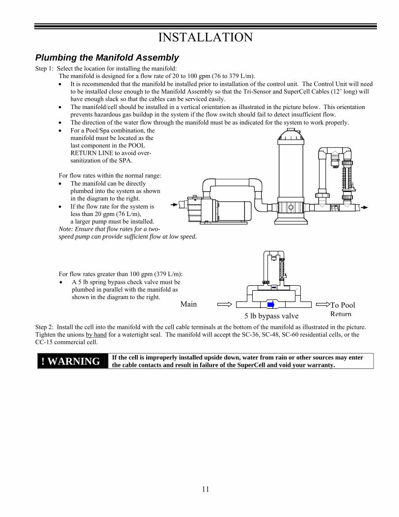
Plumbing the Manifold Assembly Step 1: Select the location for installing the manifold: The manifold is designed for a flow rate of 20 to 100 gpm (76 to 379 L/m).
• It is recommended that the manifold be installed prior to installation of the control unit. The Control Unit will need to be installed close enough to the Manifold Assembly so that the Tri-Sensor and SuperCell Cables (12’ long) will have enough slack so that the cables can be serviced easily.
• The manifold/cell should be installed in a vertical orientation as illustrated in the picture below. This orientation prevents hazardous gas buildup in the system if the flow switch should fail to detect insufficient flow.
• The direction of the water flow through the manifold must be as indicated for the system to work properly. • For a Pool/Spa combination, the
manifold must be located as the last component in the POOL RETURN LINE to avoid over-sanitization of the SPA.
For flow rates within the normal range:
• The manifold can be directly plumbed into the system as shown in the diagram to the right.
• If the flow rate for the system is less than 20 gpm (76 L/m), a larger pump must be installed.
Note: Ensure that flow rates for a two-speed pump can provide sufficient flow at low speed.
For flow rates greater than 100 gpm (379 L/m):
• A 5 lb spring bypass check valve must be plumbed in parallel with the manifold as shown in the diagram to the right.
Step 2: Install the cell into the manifold with the cell cable terminals at the bottom of the manifold as illustrated in the picture. Tighten the unions by hand for a watertight seal. The manifold will accept the SC-36, SC-48, SC-60 residential cells, or the CC-15 commercial cell.
! WARNING If the cell is improperly installed upside down, water from rain or other sources may enter the cable contacts and result in failure of the SuperCell and void your warranty.
5 lb bypass valve
Main Fl
To Pool Return

INSTALLATION
12
Mounting the #75003 Pool Pilot Digital Control Unit Caution: All electrical connections should be made by a licensed electrician or certified electrical contractor. Your Pool Pilot Digital is suitable for indoor or outdoor mounting. If it is connected to 230 Vac, it must be installed at least 5’ (1.5m) horizontal distance from the pool or spa wall (or more if local codes require). If it is connected to 115 Vac, it must be installed at least 10’ (3m) horizontal distance from the pool or spa wall. The Pool Pilot Digital is designed to mount vertically on a flat surface with the wiring inputs facing downward. The enclosure is designed to allow heat to dissipate from inside the box. It is important not to block the top or bottom of the box. Do NOT mount the unit inside a panel or a tightly enclosed area without proper ventilation. The cover of the Pool Pilot Digital is removed from the sides by four thumbscrews so it is advisable to leave adequate space on the sides for hand access to the thumbscrews. When selecting a location for installing the Pool Pilot Digital, please note that the Tri-Sensor and SuperCell cables are 12’ (3.6 m) long. Warning: Verify that the selected Pool Pilot Digital location is close enough to the Manifold Assembly so that the Tri-Sensor and SuperCell Cables will have enough slack so that the cables can be easily handled for service or maintenance. Read the following section completely before proceeding (damage to wires and connectors may occur):
1. Level and tape the mounting template to the selected mounting location. Mark the wall for the 4 mounting holes.
2. Plastic anchors and screws have been provided for concrete or stucco walls. Drill and install the plastic anchors and/or screws. Leave a ¼” gap from the wall when tightening the screws.
3. Loosen but do not remove the 4 thumbscrews on the sides of the Control Unit. (2 thumbscrews on each side)
4. Carefully slide off the outer housing cover. Disconnect the 3 plugs that connect to the display board (indicated by ) that is mounted inside the cover. (The display circuit board does not need to be removed from the cover.)
5. Safely set the cover aside.
6. Hang the Pool Pilot Digital on the four mounting screws. Using a long shaft slotted screwdriver, tighten the screws through the black plastic access holes (indicated by ).
7. For access to the electrical terminal strip, remove the four screws and lift off the inner metal protective cover.
8. Route the (2) ribbon connectors from the display circuit board side through the slotted access hole, then remove the (1) power plug on the power circuit board side and route through the slotted access hole.
9. Safely set the metal protective cover aside. 10. See Electrical Connections on pgs. 13 – 15 for terminal connections. 11. Reverse steps 3 - 8 to re-install the metal and outer covers. Make sure to route and connect the ribbon
connectors and power plug through the metal protective cover properly, then replace the outer housing cover after first connecting the 3 plugs (that were disconnected in Step 4).
CHECK SYSTEM
BOOST MENU SELECT PUMP

INSTALLATION
13
Optional 115 Volt configuration
230 Volt factory configuration
Electrical Connections The Pool Pilot Digital uses both high and low voltage connections. High voltage connections will be made for providing the direct input power to it. Additional high voltage connections may be made to the filter pump from the Pool Pilot Digital. Low voltage connections will be made to the Tri-Sensor and SuperCell. Additional low voltage connections are provided for optional equipment such as #75008 pH feeder, #75001 Pool Chemistry Controller, or an ORP or electronic control.
! DANGER
Ensure that power is disconnected before wiring this unit. Follow all state / local / NEC (CEC if applicable) electrical codes. Use copper conductors only.
Grounding and Bonding Connect a ground wire from the primary electrical input to the grounding lug located inside the box. Also ground any piece of high voltage equipment that is connected to the Pool Pilot Digital relay. The Pool Pilot Digital must also be connected to the pool bonding system with an 8AWG (6AWG for Canada) wire. A lug is provided on exterior of the unit at the bottom.
High Voltage Wiring
Converting from 230 Vac to 115Vac The #75003 Pool Pilot Digital has been configured at the factory for 230Vac service. Verify that this is the desired input voltage configuration. If 115Vac input power is required, follow the directions below to convert the input voltage.
• If the cover has not been removed, review the steps in Mounting the #75003 Pool Pilot Digital on pg. 12 for instructions on removing the cover and disconnecting the cable plugs at the display board.
• Remove the single jumper wire and re-attach as shown in the diagram.
• Locate the jumper wire provided in the installation kit and attach as shown in the diagram.
INSTALLATION
14
High Voltage Wiring
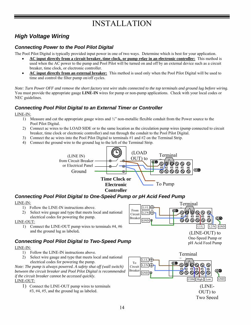
Connecting Power to the Pool Pilot Digital The Pool Pilot Digital is typically provided input power in one of two ways. Determine which is best for your application.
• AC input directly from a circuit breaker, time clock, or pump relay in an electronic controller: This method is used when the AC power to the pump and Pool Pilot will be turned on and off by an external device such as a circuit breaker, time clock, or electronic controller.
• AC input directly from an external breaker: This method is used only when the Pool Pilot Digital will be used to time and control the filter pump on/off cycles.
Note: Turn Power OFF and remove the short factory test wire stubs connected to the top terminals and ground lug before wiring. You must provide the appropriate gauge LINE-IN wires for pump or non-pump applications. Check with your local codes or NEC guidelines.
Connecting Pool Pilot Digital to an External Timer or Controller LINE-IN:
1) Measure and cut the appropriate gauge wires and ½” non-metallic flexible conduit from the Power source to the Pool Pilot Digital. 2) Connect ac wires to the LOAD SIDE or to the same location as the circulation pump wires (pump connected to circuit breaker, time clock or electronic controller) and run through the conduit to the Pool Pilot Digital. 3) Connect the ac wires into the Pool Pilot Digital to terminals #1 and #2 on the Terminal Strip. 4) Connect the ground wire to the ground lug to the left of the Terminal Strip.
Connecting Pool Pilot Digital to One-Speed Pump or pH Acid Feed Pump LINE-IN:
1) Follow the LINE-IN instructions above. 2) Select wire gauge and type that meets local and national electrical codes for powering the pump.
LINE-OUT: 1) Connect the LINE-OUT pump wires to terminals #4, #6 and the ground lug as labeled.
Connecting Pool Pilot Digital to Two-Speed Pump LINE-IN:
1) Follow the LINE-IN instructions above. 2) Select wire gauge and type that meets local and national electrical codes for powering the pump.
Note: The pump is always powered. A safety shut off (wall switch) between the circuit breaker and Pool Pilot Digital is recommended if the circuit breaker cannot be accessed quickly. LINE-OUT:
1) Connect the LINE-OUT pump wires to terminals #3, #4, #5, and the ground lug as labeled.
(LINE-OUT) to
Two Speed
Terminal St i
#1 #2 #3 #4 #5 #6 GND
L1/L
L2/N
To
Circuit Breaker
GNDLowHighCOM
Time Clock or Electronic Controller
R l
(LINE IN) from Circuit Breaker or Electrical Panel
(LOAD OUT) to
Terminal St i#1 #2 #3 #4 #5 #6
Ground
To Pump
(LINE-OUT) to One-Speed Pump or pH Acid Feed Pump
Terminal St i#1 #2 #3 #4 #5 #6
GND
L1/L
L2/N
From
Circuit Breaker
GNDL2/NL1/L
INSTALLATION
15
Digital Control Panel Base Plate Ground Lug Cell Cord C t
Tri-sensor assembly
Low voltage wiring
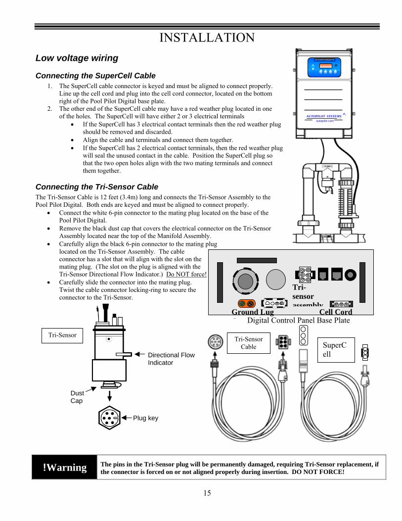
Connecting the SuperCell Cable 1. The SuperCell cable connector is keyed and must be aligned to connect properly.
Line up the cell cord and plug into the cell cord connector, located on the bottom right of the Pool Pilot Digital base plate.
2. The other end of the SuperCell cable may have a red weather plug located in one of the holes. The SuperCell will have either 2 or 3 electrical terminals
• If the SuperCell has 3 electrical contact terminals then the red weather plug should be removed and discarded.
• Align the cable and terminals and connect them together. • If the SuperCell has 2 electrical contact terminals, then the red weather plug
will seal the unused contact in the cable. Position the SuperCell plug so that the two open holes align with the two mating terminals and connect them together.
Connecting the Tri-Sensor Cable The Tri-Sensor Cable is 12 feet (3.4m) long and connects the Tri-Sensor Assembly to the Pool Pilot Digital. Both ends are keyed and must be aligned to connect properly.
• Connect the white 6-pin connector to the mating plug located on the base of the Pool Pilot Digital.
• Remove the black dust cap that covers the electrical connector on the Tri-Sensor Assembly located near the top of the Manifold Assembly.
• Carefully align the black 6-pin connector to the mating plug located on the Tri-Sensor Assembly. The cable connector has a slot that will align with the slot on the mating plug. (The slot on the plug is aligned with the Tri-Sensor Directional Flow Indicator.) Do NOT force!
• Carefully slide the connector into the mating plug. Twist the cable connector locking-ring to secure the connector to the Tri-Sensor.
!Warning
The pins in the Tri-Sensor plug will be permanently damaged, requiring Tri-Sensor replacement, if the connector is forced on or not aligned properly during insertion. DO NOT FORCE!
Directional Flow Indicator
Dust Cap
Plug key
Tri-Sensor Cable Tri-Sensor
Cable SuperCell
AUTOPILOT SYSTEMS INC
autopilot.com
INSTALLATION
16
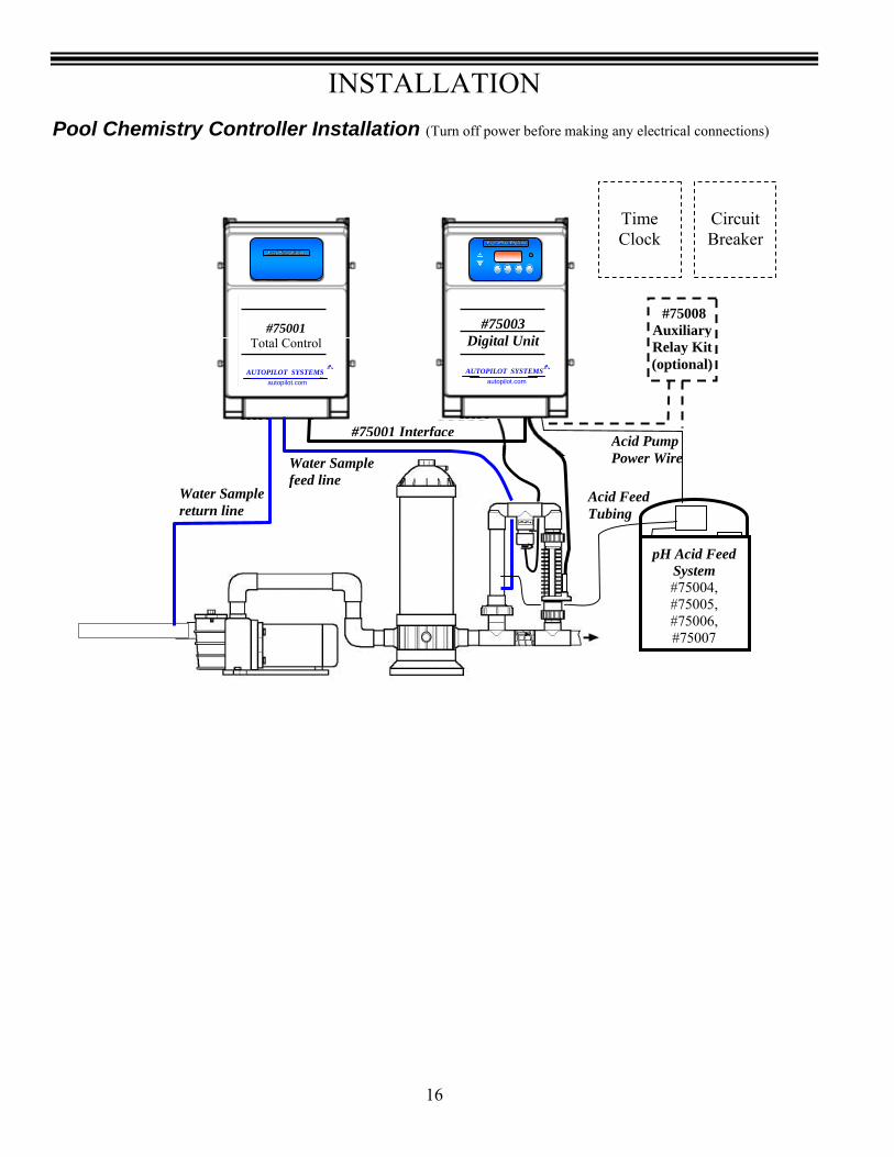
Pool Chemistry Controller Installation (Turn off power before making any electrical connections)
Electronic Controller
System
#75008 Auxiliary Relay Kit (optional) AUTOPILOT SYSTEMS
INC
autopilot.com AUTOPILOT SYSTEMS INC
autopilot.com
#75001 Total Control
Water Sample return line
Water Sample feed line
Acid Pump Power Wire
#75001 Interface
Acid Feed Tubing
pH Acid Feed System #75004, #75005, #75006, #75007
Time Clock
Circuit Breaker
#75003 Digital Unit

INSTALLATION
17
Before Installing the #75001 Pool Pilot Pool Chemistry Controller System or the #75004, #75005, #75006, or #75007 pH Acid Feed Pump and Tank System
• Determine that everything needed for installation is on hand • Find a suitable mounting location for the Pool Chemistry Controller Unit within proper cord length to the Digital Control
Unit • Find a suitable mounting location for the Stenner acid feeder and tank. • Plan tubing runs for Flow Cell water sample tubing and Acid Feed lines • For optional #75008 pH Auxiliary Relay Kit, plan for electrical connections
What is included? Before attempting the Total Control installation, check that the following items have been included with the Pool Chemistry Controller:
Quantity Item Description 1 #75001 Pool Chemistry Control unit with Flow cell, flow
switch, and interface cable 1 ORP sensor (in storage cap) 1 pH sensor (in storage cap) 1 Total Control interface cable 1 Mounting Template 4 Plastic Mounting Wall Anchors 4 Mounting Screws
16’ (5.3 m) 3/8” Water Sample tubing 2 Injection Fitting with gasket and S.S. saddle clamp 1 In-line check valve adapter fitting
Before attempting the pH Acid Feed Pump and Tank Kit installation, check that the following items have been included with the pH Control System:
For #75008 Auxiliary Relay Kit
Quantity Item Description 1 Auxiliary Relay box with internal relay and interface cable 4 Plastic Mounting Wall Anchors 4 Mounting Screws
What is not included Some of the additional equipment that is needed to complete the installation:
• Drill with 3/8” bit • Utility Knife
For installations using Stenner Factory Tube and Fittings • ¼” NPT drill and tap kit • Teflon Tape
For #75008 auxiliary relay kit • Appropriate gauge electrical wire • ½”liquidtite (non-metallic flex) conduit • ½” conduit connector for service to the Pool Pilot Digital Control unit
Quantity Item Description 1 Stenner pH acid feed pump with 15 gallon acid tank 1 Injection Fitting with gasket and S.S. saddle clamp 1 In-line check valve adapter fitting
8’ (2.7 m) 1/8” ID x ¼” OD tubing 1 Cable Clamp and Nut assembly
1 pkg Stenner Factory Parts Kit (fittings and components)
INSTALLATION
18
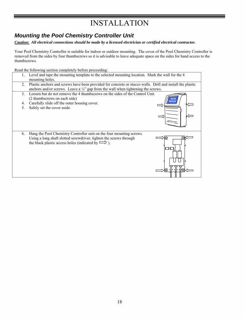
Mounting the Pool Chemistry Controller Unit Caution: All electrical connections should be made by a licensed electrician or certified electrical contractor. Your Pool Chemistry Controller is suitable for indoor or outdoor mounting. The cover of the Pool Chemistry Controller is removed from the sides by four thumbscrews so it is advisable to leave adequate space on the sides for hand access to the thumbscrews. Read the following section completely before proceeding:
1. Level and tape the mounting template to the selected mounting location. Mark the wall for the 4 mounting holes.
2. Plastic anchors and screws have been provided for concrete or stucco walls. Drill and install the plastic anchors and/or screws. Leave a ¼” gap from the wall when tightening the screws.
3. Loosen but do not remove the 4 thumbscrews on the sides of the Control Unit. (2 thumbscrews on each side)
4. Carefully slide off the outer housing cover. 5. Safely set the cover aside.
6. Hang the Pool Chemistry Controller unit on the four mounting screws. Using a long shaft slotted screwdriver, tighten the screws through the black plastic access holes (indicated by ).
INSTALLATION
19
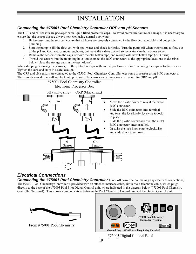
Connecting the #75001 Pool Chemistry Controller ORP and pH Sensors The ORP and pH sensors are packaged with liquid filled protective caps. To avoid premature failure or damage, it is necessary to ensure that the sensor tips are always kept wet, using normal pool water.
1. Before inserting the sensors, ensure that all hoses are properly connected to the flow cell, manifold, and pump inlet plumbing.
2. Start the pump to fill the flow cell with pool water and check for leaks. Turn the pump off when water starts to flow out of the pH and ORP sensor mounting holes, but leave the valves opened so the water can drain down some.
3. Remove the sensors from the caps, remove the old Teflon tape, and rewrap with new Teflon tape (2 - 3 turns). 4. Thread the sensors into the mounting holes and connect the BNC connectors to the appropriate locations as described
below (place the storage caps in the cap holders). When shipping or storing the sensors, fill the protective caps with normal pool water prior to securing the caps onto the sensors. Tighten the caps and store in a safe location. The ORP and pH sensors are connected to the #75001 Pool Chemistry Controller electronic processor using BNC connectors. These are designed to install and lock into position. The sensors and connectors are marked for ORP and pH.
Electrical Connections Connecting the #75001 Pool Chemistry Controller (Turn off power before making any electrical connections) The #75001 Pool Chemistry Controller is provided with an attached interface cable, similar to a telephone cable, which plugs directly to the base of the #75003 Pool Pilot Digital Control unit, where indicated in the diagram below (#75001 Pool Chemistry Controller Terminal). This allows communication between the Pool Chemistry Control unit and the Digital Control unit.
#75003 Digital Control Panel B Pl t
#75001 Pool Chemistry Controller Terminal
Ground Lug #75008 Auxiliary Relay Terminal
From #75001 Pool Chemistry
• Move the plastic cover to reveal the metal BNC connector.
• Slide the BNC connector onto terminal and twist the lock knob clockwise to lock in place.
• Slide the plastic cover back over the metal BNC connector once installed.
• Or twist the lock knob counterclockwise and slide down to remove.
#75001 Pool Chemistry Controller Electronic Processor Box
pH (white ring) ORP (black ring)
pH Sensor
ORP Sensor

INSTALLATION
20
#75003 Digital Control Panel Base Plate
pH Installation Connecting the pH Acid Feed Pump (Turn off power before making any electrical connections) The electrical instructions will depend on the Set Relay 1 configuration of the Pool Pilot Digital (#75003) – see pg. 34.
• One Speed or Two Speed Pump – Digital is controlling the main circulation pump Note: The AC Power Source voltage and the Stenner Acid Feed Pump voltage must match one another.
(Auxiliary Relay Kit, #75008 is required - complete mounting and wiring instructions are included with the kit): 1. Mount the #75008 Auxiliary Relay box the proper distances between the Control Unit and acid feed pump and tank. 2. Plug the flat 4-position connector into the Digital unit base plate, shown below as #75008 Auxiliary Relay Terminal. 3. Route the Input ac power wires through Liquidtite conduit, from the AC Power Source to the Auxiliary Relay. These
wires should be connected to the Auxiliary Relay terminals marked Line 1 and Line 2. 4. Cut off the existing ac plug on the acid feed pump and route this cord into the Auxiliary Relay, through the strain
relief fitting provided on the Relay box, shown below as “To Acid Pump”. 5. Cut back the cord jacket approximately 3” (7.2 cm) and strip the wires approximately ½” (1.5 cm). 6. Insert these wires into the Auxiliary Relay terminals marked Load 1 and Load 2. 7. Connect the Green Ground wires together with the provided wire nut, and then go to Step 4 below.
• Acid Pump – Digital is controlling the Stenner Acid Pump Note: The Pool Pilot Digital voltage and the Stenner Acid Feed Pump voltage must match one another.
1. Cut off the existing ac plug on the acid feed pump and route this cord into the Pool Pilot Digital Control unit Control Unit, through a strain relief fitting provided with the pH Acid Feed Pump Installation Kit.
2. Cut back the cord jacket approximately 3” (7.3 cm) and strip the wires approximately ½” (1.3 cm) and insert into terminal strip #4 and #6.
3. Connect the Green Ground wire to the ground lug.
4. Complete the plumbing of the acid tank – see pg. 22. 5. Set the “Select System” mode to “pH Control” – see pg. 35.
(LINE-OUT) to Acid Feeder
#1 #2 #3 #4 #5 #6 GND
L1/L
L2/N
To
Circuit Breaker
GNDL2/NL1/L
#75003 Digital Control Unit Terminal Strip
Ground Lug #75008 Auxiliary
AC Power Conduit or Strain relief fitting for A id P t l
#75008 Auxiliary Relay Kit
Load Line Load Line 1 1 2 2
To Acid Pump Flexible conduit to ac Power Source
Prewired Plug to #75008 Terminal

INSTALLATION
21
➀ ②
Optional Tap Points For
Digital TC Total Control
Acid In Water Out
Tap Point Locations
Always Insert tubing into appropriate inlet/outlet. See Digital TC manual for drilling instructions.
Optional Tap Points
For Digital TC
Total Control
Always Insert tubing
into appropriate inlet/outlet.
See Digital TC manual
for drilling instructions.
Acid In Water Out
Tap PointLocations
Pool Chemistry Controller Flow Cell Plumbing It is necessary to have a constant flow to the flow cell to ensure accurate water sampling. This is done by locating the water sample tubes as indicated in the diagram on pg. 16. Have these tools on hand prior to starting this step:
• Drill • 1/2” standard drill bit • Utility knife
Water Sample Feed Tube A hole must be drilled into the manifold assembly for installation of the injector fitting for the Water Sample Feed Line.
1. Turn the pump off, disconnect the cell and tri-sensor cords, and remove the manifold piping (without the cell) to a clean working area. See diagram above for which unions to remove (marked ➀ in diagram).
2. Locate the label on the manifold assembly marked “Optional Tap Points” (marked ② in diagram), and drill the appropriate mounting hole adjacent to where indicated on the label marked “Water Out”. Do not drill through the label! Use a drill stop attachment if available, or wrap a piece of masking tape, exposing 1” of the tip of the drill bit as a stop indicator. This will prevent drilling through the far side of the PVC, damaging the manifold.
Note: Use care to drill the hole perpendicular and deburr, for a leak-free connection of the injector fitting. Do not over drill or ream the hole as oversized holes will leak and are not covered under warranty. 3. Insert the Uniseal fitting into the hole. Note: Do not use any lubrication or sealing compounds! 4. Insert the Black Water sample tube approx 1” into the Uniseal fitting. 5. Roll out the tubing and connect into the Flow Cell Inlet valve (left side),
ensuring a squared edge. 6. Leave enough slack in the tubing to secure the tubing with ty-wraps.
!Caution Avoid any sharp bends and over tightening the ty-wrap to the tubing, which can hinder proper flow of the chemicals
Water Sample Return Tube The Flow cell sample return tube must be connected to the suction side of the circulation pump. This can be done by drilling a ½” hole in the pipe and using the Uniseal fitting, or by Drill and Tapping, then threading the Stenner ¼” NPT fitting in the pipe. Using the Uniseal fitting (Turn Pump Off prior to drilling into the pipe):
1. Mark a spot on a straight section of suction pipe into the pump. Make sure it is after all suction valves and directly into the pump suction.
2. Drill a ½” hole. Use a drill stop attachment if available, or wrap a piece of masking tape, exposing 1” of the tip of the drill bit as a stop indicator. This will prevent drilling through the far side of the PVC, damaging the pipe.
Note: Use care to drill the hole perpendicular and deburr, for a leak-free connection of the injector fitting. Do not over drill or ream the hole as oversized holes will leak and are not covered under warranty. 3. Insert the Uniseal Fitting into the hole. 4. Insert the black water sample tubing into the suction side fitting. 5. Roll out the tubing and connect into the Flow Cell Outlet valve (right side), ensuring a squared edge. 6. Leave enough slack in the tubing to secure the tubing with ty-wraps. 7. Install the ORP and pH sensors as shown on pg. 19. 8. Turn the pump on and check for leaks. A 6” section of tubing can be inserted into the water sample valve (middle valve) to allow better access to take a water sample from the flow cell.

INSTALLATION
22
➀ ②
Optional Tap Points For
Digital TC Total Control
Acid In Water Out
Tap Point Locations
Always Insert tubinginto appropriate inlet/outlet. See Digital TC manual for drilling instructions.
Stenner Acid Pump and Tank
Kit
pH Control Installation
Plumbing Have these tools on hand prior to starting this step:
• Drill • 1/2” standard drill bit (or 1/4” NPT bit and tap if using Stenner
components) • Utility knife
A hole must be drilled into the manifold assembly for installation of the injector fitting for the Muriatic Acid.
1. Locate the Acid Feed Pump and tank within proper cord distances to the Pool Chemistry Controller System and Power source. 2. Turn the pump off, disconnect the cell and tri-sensor cords,
and remove the manifold piping (without the cell) to a clean working area. See diagram for which unions to remove (marked ➀in diagram above).
3. Locate the label on the manifold assembly marked “Optional Tap Points” (marked ② in diagram above), and drill the appropriate mounting hole adjacent to where indicated on the label marked “Acid In”. Do not drill through the label! Use a drill stop attachment if available, or wrap a piece of masking tape, exposing 1” of the tip of the drill bit as a stop indicator. This will prevent drilling through the far side of the PVC, damaging the manifold.
Note: Use care to drill the hole perpendicular and deburr, for a leak-free connection of the injector fitting. Do not over drill or ream the hole as oversized holes will leak and are not covered under warranty.
Follow steps #4 and 5 if using Autopilot factory components or skip to #6 if using Stenner factory components 4. Insert the black injector fitting (Uniseal) into the ½” hole.
Note: Do not use any lubrication or sealing compounds! 5. Insert the one-direction check valve assembly into the Uniseal, and then insert the Autopilot supplied
black plastic tubing (marked 1/8” ID x ¼” OD) onto the check valve. Ensure the tubing is square edged before inserting (use the utility knife to cut if needed). Note: If it seems too tight, use some water or dishwashing detergent. Do not use any other lubricants!
6. IF USING THE STENNER FACTORY COMPONENTS, FOLLOW THE INSTRUCTIONS IN THE STENNER INSTALLATION MANUAL AND USE ALL STENNER SUPPLIED TUBING AND FITTINGS as Autopilot and Stenner factory tubing and fittings are not interchangeable.
7. If the acid collection tube has not already been installed, do so at this time. This will connect to the closer fitting on the Stenner head assembly.
8. Roll out the tubing to connect into the Acid Feed Pump, again ensuring a squared edge. Leave enough slack in the tubing to secure the tubing with ty-wraps.
! Warning
Avoid any sharp bends and over tightening the Ty-Wrap to the tubing, which can hinder proper flow of the chemicals
9. Remove the tank access lid and adjust the Stenner acid tank tubing weight so that it is about 1/2” (1.5 cm) from the bottom of the tank. 10. Add 1 – 2 gallons of water into the acid tank.
STOP! At this point, turn on the circulation pump and perform the “Prime Acid Pump”, see pg. 35, and check for any leaks in the acid tubing and fittings.
11. Once secured and adjusted, continue adding water and muriatic acid into the tank for a recommended acid mixture of 4 parts water to 1 part muriatic acid dilution.
! Warning To avoid damaging splashes, ALWAYS ADD ACID TO WATER, never water to acid.
Optional Tap Points
For Digital TC
Total Control
Acid In Water Out
Tap PointLocations
Always Insert tubinginto appropriate inlet/outlet. See Digital TC manual
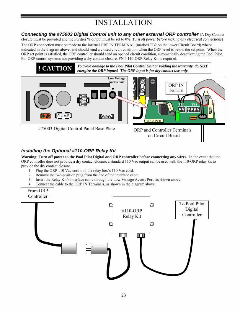
INSTALLATION
23
Connecting the #75003 Digital Control unit to any other external ORP controller (A Dry Contact closure must be provided and the Purifier % output must be set to 0%. Turn off power before making any electrical connections) The ORP connection must be made to the internal ORP IN TERMINAL (marked TB2 on the lower Circuit Board) where indicated in the diagram above, and should send a closed circuit condition when the ORP level is below the set point. When the ORP set point is satisfied, the ORP controller should send an opened circuit condition, automatically deactivating the Pool Pilot. For ORP control systems not providing a dry contact closure, PN # 110-ORP Relay Kit is required.
Installing the Optional #110-ORP Relay Kit Warning: Turn off power to the Pool Pilot Digital and ORP controller before connecting any wires. In the event that the ORP controller does not provide a dry contact closure, a standard 110 Vac output can be used with the 110-ORP relay kit to provide the dry contact closure.
1. Plug the ORP 110 Vac cord into the relay box’s 110 Vac cord. 2. Remove the two-position plug from the end of the interface cable. 3. Insert the Relay Kit’s interface cable through the Low Voltage Access Port, as shown above. 4. Connect the cable to the ORP IN Terminals, as shown in the diagram above.
! CAUTION To avoid damage to the Pool Pilot Control Unit or voiding the warranty, do NOT energize the ORP inputs! The ORP input is for dry contact use only.
ORP and Controller Terminals on Circuit Board
# 838 PCB
TB1
ORP IN Terminal
Low Voltage Access Port
#75003 Digital Control Panel Base Plate
TB2
From ORP Controller
To Pool Pilot Digital
Controller #110-ORP Relay Kit
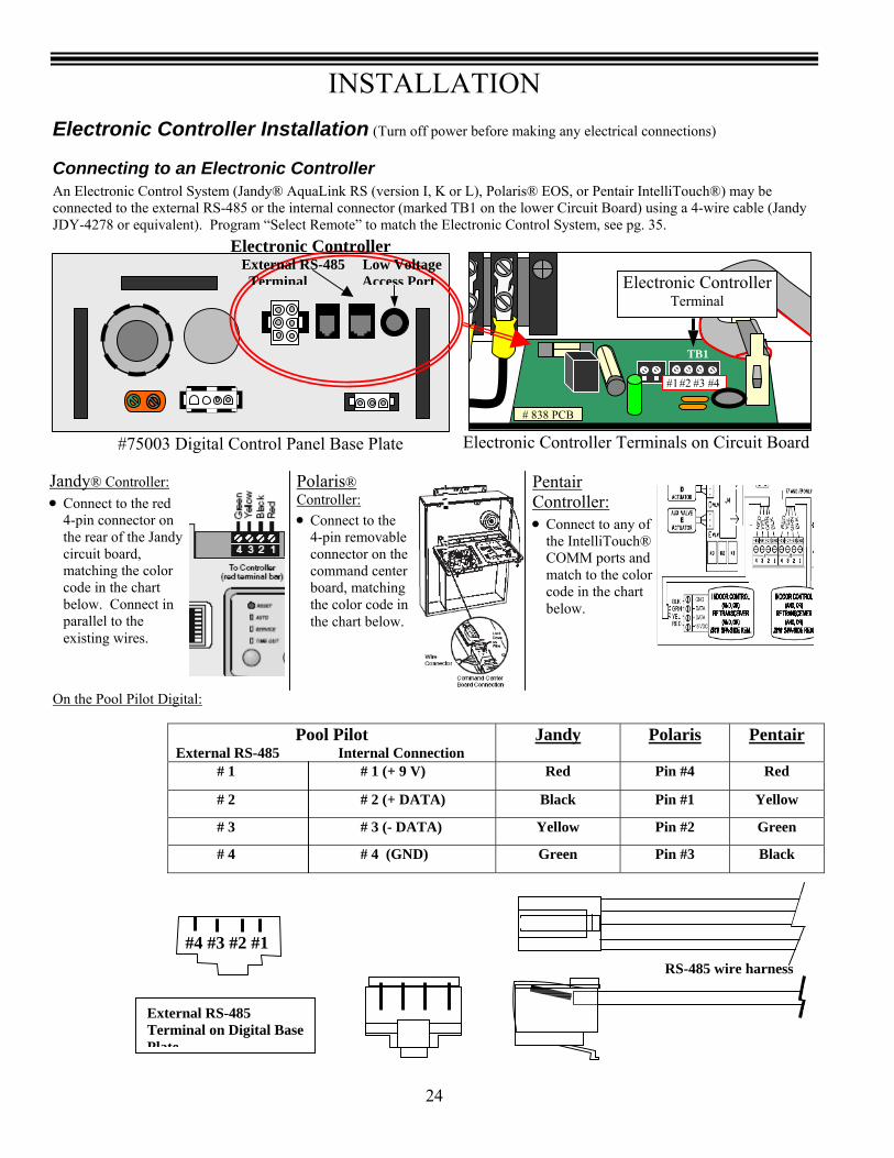
INSTALLATION
24
Electronic Controller Installation (Turn off power before making any electrical connections)
Connecting to an Electronic Controller An Electronic Control System (Jandy® AquaLink RS (version I, K or L), Polaris® EOS, or Pentair IntelliTouch®) may be connected to the external RS-485 or the internal connector (marked TB1 on the lower Circuit Board) using a 4-wire cable (Jandy JDY-4278 or equivalent). Program “Select Remote” to match the Electronic Control System, see pg. 35.
On the Pool Pilot Digital:
Pool Pilot
External RS-485 Internal Connection Jandy Polaris Pentair
# 1 # 1 (+ 9 V) Red Pin #4 Red
# 2 # 2 (+ DATA) Black Pin #1 Yellow
# 3 # 3 (- DATA) Yellow Pin #2 Green
# 4 # 4 (GND) Green Pin #3 Black
Jandy® Controller: • Connect to the red
4-pin connector on the rear of the Jandy circuit board, matching the color code in the chart below. Connect in parallel to the existing wires.
Polaris® Controller: • Connect to the
4-pin removable connector on the command center board, matching the color code in the chart below.
Pentair Controller: • Connect to any of
the IntelliTouch® COMM ports and match to the color code in the chart below.
Electronic Controller Terminals on Circuit Board
# 838 PCB
TB1
#1 #2 #3 #4
Electronic ControllerTerminal
#75003 Digital Control Panel Base Plate
Electronic Controller External RS-485 Low Voltage
Terminal Access Port
RS-485 wire harness
#4 #3 #2 #1
External RS-485 Terminal on Digital Base Plate

MENU OVERVIEW
25
Menu Overview Use this menu overview for quick reference to the menu program sequence. Some menu features will only display with specific System Configurations, as noted below. We recommend contacting Autopilot systems when access to the “Protected Access” menus is desired. Main Menu NotesTest pool pilot 1 Control Main PumpView setup 2 Control One speed pumpOwner options 3 Control Acid pumpMaintenance menu 4 Sensors InstalledInstaller menu 5 5 Protected AccessEnd menu mode
Test Pool Pilot Installer Menu View Setup Maintenance MenuSalt Select language Software version Set time of daySalt needed Select units OpEC version 4 Force reverseTemperature Temperature unit Serial number Set reverse timeCell V/A Set 12/24 Hour Clock Cell type Enable/Disable remoteAmp Hrs Set time of day Power level Replace cell 5oz/ml Acid Fed 3 Set pool volume Pool size Set prime protect 2ORP(ORP setpoint) 4 Set cell type Reverse time Set pump program 1 1pH(pH setpoint) 4 Set cell power Temp adjust Set pump program 2 1
Set relay 1 Salt adjust Calibrate saltOwner Options Set prime protect 2 Select system mode Calibrate temperatureSelect language Set pump program 1 1 ORP overfeed 4 Prime acid pump 3Select units Set pump program 2 1 pH overfeed 4 Reset acid meter 3Temperature unit Select remote pH minimum 4 Enable/Disable acid 3Set 12/24 Hour Clock Select system pH maximum 4 Set pH overfeed 4Set time of day End menu mode Relay 1 mode Set pH min 4Set pump program 1 1 Prime protect 2 Set pH max 4Set pump program 2 1 Pump program 1 1 Calibrate pH 4Boost acid 4 Select System Pump program 2 1 Enable/Disable ORP 4End menu mode Purifier Remote version Set ORP overfeed 4
pH control 3 Freeze protect 2 End menu modeTotal control 4Sensor flow 4
Set relay 1One speed pumpTwo speed pumpAcid pumpRelay not used
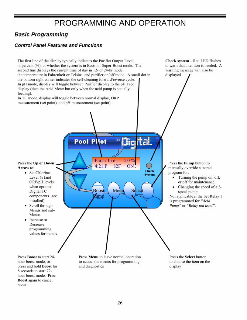
PROGRAMMING AND OPERATION
26
Basic Programming
Control Panel Features and Functions
The first line of the display typically indicates the Purifier Output Level in percent (%), or whether the system is in Boost or Super-Boost mode. The second line displays the current time of day in 12- or 24-hr mode, the temperature in Fahrenheit or Celsius, and purifier on/off mode. A small dot in the bottom right corner indicates the self-cleaning forward/reverse cycle. In pH mode, display will toggle between Purifier display to the pH Feed display (then the Acid Meter but only when the acid pump is actually feeding). In TC mode, display will toggle between normal display, ORP measurement (set point), and pH measurement (set point)
Check system – Red LED flashes to warn that attention is needed. A warning message will also be displayed.
Press the Up or Down Arrow to:
• Set Chlorine Level % (and ORP/pH levels when optional Digital TC components are installed)
• Scroll through Menus and sub-Menus
• Increase or Decrease programming values for menus
Press the Pump button to manually override a stored program for:
• Turning the pump on, off, or off for maintenance.
• Changing the speed of a 2-speed pump.
Not applicable if the Set Relay 1 is programmed for “Acid Pump” or “Relay not used”.
Press Boost to start 24-hour boost mode, or press and hold Boost for 8 seconds to start 72-hour boost mode. Press Boost again to cancel boost.
Press Menu to leave normal operation to access the menus for programming and diagnostics
Press the Select button to choose the item on the display
P u r i f i e r 5 0 % 4:21 P 82F ON .
Pool Pilot ™
Check System
Boost Menu Select Pump
PROGRAMMING AND OPERATION
27
Control Options There are three different modes of operation.
• Purifier (factory setting) • pH Control • Total Control
Purifier Mode The Control Unit normally runs in the manually controlled purifier mode. In this mode the Pool Pilot will automatically display informative messages about the condition of the chlorinator (Purifier Output %, time of day, water temperature, warning messages, etc.) and requires manual adjustment of purifier % setting, as described on pg. 27. The Pool Pilot will revert to this normal display if there is no activity on the keypad for 13 or more seconds. Purifier % Start Up - the normal startup procedure is as follows:
1. Balance your water chemistry according to the water chemistry parameters. See Basic Water Chemistry on pgs 7 - 8. 2. Add the proper amount of salt as indicated by the Pool Pilot (or as described in Salt Level on pg. 6) and run the
circulation pump continuously for 24 hours for the salt to be fully mixed and dissolved into the pool. If the salt level is too low, the Pool Pilot® Digital will warn you and will not generate purifier until the minimum salt level is reached.
3. Use the up and down arrow buttons to set the purifier % to 50% and allow the pool to operate normally. For the first two weeks, test the water chemistry parameters every 3-4 days. Adjust chemicals as needed. For the Free Chlorine adjustment, use the following table for the adjustment procedure.
Purifier % currently set to:
If Free Chlorine is lower than ideal range
If Free Chlorine is higher than ideal range
0% - 25% The Purifier % output needs to be increased. (The Cell Power is probably set correctly.) 1) Use the up arrow button to increase the Purifier
Output %
The CELL POWER setting is too high. 1) Decrease the Cell Power one level to lower the
maximum output. 2) Use the up arrow button to set the Purifier Output to
50%. The Free Chlorine will need to be tested frequently and the Purifier Output % will need to be adjusted as needed to attain desired level.
25% to 75% The Purifier % output needs to be increased. (The Cell Power is probably set correctly.) 1) Use the up arrow button to increase the Purifier
Output %
The Purifier % output needs to be decreased. (The Cell Power is probably set correctly.) 1) Use the down arrow button to decrease the Purifier
Output % 75% - 100% The CELL POWER setting may be too low.
1) Increase the Cell Power one level to raise the maximum output.
2) Use the down arrow button to set the Purifier Output to 50%. The Free Chlorine will need to be tested frequently and the Purifier Output % will need to be adjusted as needed to attain the desired level.
Additional increases can be made by extending the pump circulation time so that the Pool Pilot can operate longer.
The Purifier % output needs to be decreased. (The Cell Power is probably set correctly.) 1) Use the down arrow button to decrease the Purifier
Output %
4. After the optimal Purifier % setting has been determined, this setting normally will not need to be adjusted, you will only need to adjust your level or select a Boost Cycle to compensate for increased bather usage or heavy rainfalls that can quickly consume chlorine.
Purifier Programming Start-up: Enter the Installer Menu and program “Set time of day” to your time zone, “Set pool volume” to your specific pool, and “Set cell type” to match the model cell installed. If the Digital is used to control the main circulation pump, also program “Relay 1”, “Prime protect”, “Pump program 1” and “Pump program 2” – see pgs. 32 - 34. In addition, there are user programmable menu display preferences including “Select language”, “Select units”, “Temperature unit”, and “12/24 clock” but are not needed for proper operation – see pg. 32.
To avoid accidental adjustments, the Cell Power can only be changed in the Installer Menu - see page 28.

PROGRAMMING AND OPERATION
28
pH Control Mode (Manually adjusted pH control and Purifier) Note: Optional pH Control Acid Tank & Pump #’s 75004, 75005, 75006, or 75007 must be installed for this mode to function. The Digital Unit must be initially programmed through the Installer Menu (Select System mode – see pg. 35), to the pH Control mode. In this mode, the Purifier and pH control are adjusted manually. The display toggles from the Purifier display to the pH Feed Display (then the Acid Meter but only when the acid pump is actually feeding). The total volume of acid dispensed is available in the “Test Pool Pilot” mode, which is reset through the Maintenance Menu and can indicate when more acid needs to be added to the tank.
pH Feed Rate Start up Adjust the Purifier levels as described on pg. 29. The pH Control is adjusted by assigning the amount of acid that is to be delivered by a feed rate pump with a user programmable fixed rate between “Acid Feed Off” to “330 oz/day” (10,000 ml/day). If the acid feed rate is not known, follow these instructions:
1. Test and record your starting pH level. See Basic Water Chemistry on pg. 7. 2. Press the Up or Down Arrow, while the display is in the pH Feed Display. The display will then show the current Feed
Rate setting. 3. Adjust the Acid Feed rate to 5 oz per day per 10,000 gallons (148 mL per day per 38,000 liters) of pool volume. 4. After adjusting the acid feed rate to the desired value, press “Select”. 5. Test the pH the following day and adjust the Acid Feed rate higher or lower as needed. 6. Repeat until your desired pH level is maintained.
This will require periodic testing and adjusting as chlorine and pH demand changes.
pH Programming Start-up: Follow the instructions from the Purifier mode for programming start up. In addition, enter the Installer Menu and program the following:
• Press MENU, press Δ or ∇ until “Installer menu” is displayed, then press and hold SELECT for approximately 13 seconds to enter Installer menu.
• Press Δ or ∇ until “Select system” is displayed, then press SELECT (Purifier is the factory setting). • Press Δ or ∇ to program “Select system” to ”pH control”, then press SELECT. • Press Δ or ∇ until “Set Relay 1” is displayed, then press SELECT (Relay not used is the factory setting) • Press Δ or ∇ to program “Set Relay 1” to “Acid pump” (controlling the Acid pump through the Digital Relay) or “One
speed pump” (controlling the Acid pump through the #75008 Auxiliary Relay Kit) depending on the configuration.
Total Control Mode - Pool Chemistry Control (PCC) Mode Note: Optional Pool Chemistry Controller #75001and pH Control Acid Tank & Pump #’s 75004, 75005, 75006, or 75007 must be installed for this mode to function. The Digital Unit can be programmed to the Total Control option in which the purifier and pH levels are monitored and controlled automatically. In this mode, ORP (purifier) and pH sensors are used to constantly test the pool water and determine whether chlorine or muriatic acid is needed to maintain proper levels. The system automatically enters the Total Control configuration if the Digital unit is able to communicate with the Pool Chemistry Controller. The system will display “Error Purifier Off” if the Digital unit is not able to communicate with the Pool Chemistry Controller. Ensure the wire interface is properly connected between the Digital unit and the Pool Chemistry Controller. The Total Control display cycles between the ORP display, pH display, and the Salt/Time of Day/Temperature display. The pH and ORP adjustment “set points” are accessible when the ORP or pH “measurement - set point” is on the display. To access through the ORP or pH display, press the arrow up or down, while the respective mode is displayed. This will then change to the specific menu to allow reprogramming the set points. To retain the new setting, press Select when finished.
Total Control Programming Start-up: Follow the Programming Start-up instructions from the Purifier and pH Control modes. Once the #75001 interface cable is connected and communicating with #75003 Digital Control unit, it will automatically program to the Total Control mode. In addition, enter the Maintenance Menu to access and program any preferences for the following fields: Set pH overfeed, Set pH min, Set pH max, Calibrate pH, Enable / Disable ORP, and Set ORP overfeed.

PROGRAMMING AND OPERATION
29
Operation of Buttons
Adjusting the Purifier Output % Press the up/down arrow buttons to enter the Purifier Adjustment mode. Adjust the purifier output percentage to the desired output, from 0% (off) to 100 % (maximum output), then Press SELECT or allow it to default back to the normal display. Typically, once the initial setting is established, very little adjustment is needed. The purifier % setting refers to the amount of time that the cell is energized within a 15-minute cycle. The system cycles on and off, as indicated on the display’s lower right display as On, when generating chlorine. Higher settings will generate more chlorine. Follow the instructions on pg. 29 to determine proper purifier % settings. Ex: 50% setting = 50% of 15 minutes or 7.5 minutes ON and 7.5 minutes OFF. 25% setting = 3.75 min ON, 11.25 min OFF Note: When operating in Total Control mode, Purifier Output is adjusted by changing the ORP set point. The Purifier Output must be set on 0% when used with an external ORP controller.
Boost or Superboost The Boost feature is used to increase the purifier % from its normal setting to 100% for a 24 hour or 72 hour cycle. When the Boost cycle expires or is manually terminated the Purifier % returns to its previous setting and normal operation.
• Boost purifier output to 100% for 24 hours. From the normal operation, press and release the BOOST button. The display will flash “Boost 24 hour ON” then “Boost Mode”.
• Boost purifier output to 100% for 72 hours. From the normal operation, press and hold the Boost button until “Boost 72 hour ON” is displayed, then release the Boost button. The display will show “Boost” for approximately 8 seconds, after that “Boost 72 hour ON” will display, then when Boost is released, “Superboost Mode” is displayed until completed.
When Boost is activated with an external time clock, the time remaining for the boost cycle is held in memory and Boost will continue when the pump restarts, until the 24 or 72 hrs are expired. With the One-Speed Pump setting programmed, the pump time clock will be overridden and run continuously, producing purifier until the end of the boost cycle. Two-Speed Pump setting will activate 100% boost for 24 or 72 hrs.
To exit Boost or Superboost mode and revert to normal operation: • Allow the Boost or Superboost cycle to expire. • Press BOOST at anytime to manually deactivate Boost or Superboost.
(The Boost button is not active when the Pool Pilot Digital is programmed to be controlled by an Electronic Controller.)
Menu Button The MENU button is used to leave the normal operation mode and enter the program and diagnostic modes. Use the Up/Down arrow and Select buttons to navigate through the menus and sub-menus. MAIN MENUS:
• Test Pool Pilot – displays various operating parameters and diagnostic results • View setup – displays the programmed setup parameters • Owner options – programs the primary operating parameters that an owner would need to change • Maintenance menu – tests and programs the primary features that a service technician would need to access when
servicing the system • Installer menu – program the initial system setup
Note: Some features are accessed or programmed in several menus to allow quick access to the features needed.
Select Button The SELECT button chooses the displayed menu option. For the Installer Menu, press and hold the SELECT button for approximately 13 seconds to access this feature.
PROGRAMMING AND OPERATION
30
Operation of Buttons (Continued)
Pump Button (This button is not active if the Set Relay 1 is programmed for “Acid Pump” or “Relay not used”. If the Pump button is pressed when programmed for one of these modes, ”Acid Pump” or ”Relay 1 not used” will display, then revert back to the normal display.) Pump Button – One-speed pump control - The Pool Pilot must be wired to control the main circulation pump and programmed for a One-speed pump for this feature to be active (see pg. 34).
With “PUMP ON”, to turn “PUMP OFF”; 1. Press PUMP. 2. “∇ - Stop Pump” will be displayed. Press ∇. 3. “pump off” will be displayed.
With “PUMP OFF”, to turn “PUMP OFF FOR SERVICE” - (This mode disables Pump operation indefinitely, until manually enabled. Boost and Pump program modes will not enable pump.)
1. Display indicates “pump off”. 2. Press PUMP. 3. Press ∇ - Maintenance 4. “PUMP OFF FOR SERVICE” and a Red CHECK SYSTEM light will now be displayed.
With “PUMP OFF FOR SERVICE”, to terminate maintenance mode and return to “PUMP OFF”.
1. Press PUMP. 2. Press Δ - End Maint. 3. Pump will be in the “pump off” status.
With “PUMP OFF”, to turn “PUMP ON”.
1. Press PUMP. 2. Press Δ - Start Pump 3. The pump will run until the pump program reaches the next scheduled turn off time
Pump Button – Two-speed pump control - The Pool Pilot must be wired to control a two-speed main circulation pump and programmed for Two-speed pump for this feature to be active. The Pool Pilot cannot turn off the pump, and can only change pump speeds, between high and low (See pg. 34).
With pump on “HIGH SPEED”, to switch to “LOW SPEED”. 1. Press PUMP. 2. Press ∇ - Low Speed 3. Pump will switch to low speed.
With pump on “LOW SPEED”, to switch to “HIGH SPEED”. 1. Press PUMP. 2. Press Δ - High Speed 3. Pump will switch to high speed.
PROGRAMMING AND OPERATION
31
MENUS (For the Installer Menu, press and hold SELECT button for approximately 13 seconds to access this feature) Running the Test Pool Pilot program (Diagnostic menu)
1. Press MENU. 2. “Test Pool Pilot” is automatically displayed, then press SELECT. 3. The display will automatically toggle through the following displays (Δ or ∇ allows manual control forward and back.
While in this feature, pressing MENU will override the remaining displays and exit back to normal operation) • “Salt =XXXX ppm (X.x g/l)” (The optimum salt level is 3000 ppm (3.0 g/l)) • “Add salt xx Lbs (xx Kg)” (The amount of salt needed to maintain 3000 ppm (3.0 g/l)) • “Temperature XX° F (XX° C)” (The temperature of the water flowing through the Tri-Sensor) • “Cell = XX V XX.x A” (The measured voltage and current that was sent to the SuperCell) • “Amp-Hrs = xxxxxx” (The amount of current times hours of operation received by the SuperCell) • “xx oz(xx ml) acid fed” (The amount of acid dispensed into the pool – when set to TCC or Acid Feed mode) • “ORP xxx” (The user programmed ORP set point – when set to TC mode) • “pH X.x” (The user programmed pH set point – when set to TC mode)
4. The unit will automatically leave the menus and revert to normal operation.
Running the View setup program (Program and parameter menu to view the current programmed settings). 1. Press MENU, press Δ or ∇ until “View Setup” is displayed, then press SELECT. 2. The display will automatically toggle through the following displays (or pressing Δ or ∇ allows manual control forward
and back. While in this feature, pressing MENU will override the remaining displays and exit back to normal operation) • “Software V X.Xx” (The version number of the Pool Pilot Digital #75003 software) • “OpEC V X.X.X ( If installed, the version number of the PCC #75001 software) • “XXXXXXXX” (The serial number of the unit may be displayed if entered) • “Cell = xC-XX” (The cell type programmed in the Installation Menu; SC-48 is the factory setting; pg. 34) • “Power level X” (The power level being sent to the cell; 2 is the factory setting; pg. 34) • “XX,XXX gallons( liters)” (The pool volume programmed in the Installation Menu; 15,000 is the factory setting;
pg. 34) • “Reverse = X hrs” (The reverse rate programmed in the Installation Menu: 4 hrs is the factory setting; pg. 33) • “Temp. adjust = X” (The temperature adjustment variation of the actual tri-sensor reading; pg. 34) • “Salt adjust + X %” (The salt calibration adjustment variation of the actual tri-sensor reading; pg. 33) • “Purifier”, “pH control” or “Total control” (The System mode selected; Purifier is the factory setting; pg. 35) • “ORP overfeed” (User programmed in the Maintenance menu. No ORP overfeed is the factory setting. Adjustable
up to 120 minutes, in 5 minute increments; pg. 36) • “pH overfeed” (User programmed in the Maintenance menu. No pH overfeed is the factory setting. Adjustable up
to 120 minutes, in 5 minute increments; pg. 36) • “pH minimum”(User programmed in the Maintenance menu. 6.5 is the factory setting; pg. 36) • “pH maximum” (User programmed in the Maintenance menu. 8.0 is the factory setting; pg. 36) • “Relay not used”, “One-speed pump”, “Two-speed pump”, or “Acid pump” (The Set Relay 1 mode selected; Relay
not used is the factory setting; pg. 34) • “Prime Protect” “ No prime protect, 1-, 2-, 4-, 8- minutes” (User programmed setting selected to protect against
pump damage due to insufficient flow or loss of prime - when set to One speed pump mode; No prime protect is the factory setting; pg. 33)
• “Pump Program 1” (User programmed Time On / Off - when set to One speed pump mode; No program is the factory setting; pg. 32)
• “Pump Program 2” (User programmed Time On / Off - when set to One speed pump mode; No program is the factory setting; pg. 32)
• “Remote X”(User programmed in the Maintenance menu to identify the electronic controller system connected to; pg. 35)
• “Freeze protect” (Will display only when set to One speed pump mode; pg. 34) 3. The unit will automatically leave the menus and revert to normal operation.
PROGRAMMING AND OPERATION
32
MENUS (For the Installer Menu, press and hold SELECT button for approximately 13 seconds to access this feature)
Programming the language for the display (Allows for personal preference language display) 1. Press MENU, press Δ or ∇ until “Owner or Installer Menu” is displayed, then press SELECT. 2. Press Δ or ∇ until “Select language” is displayed, then press SELECT (English is the factory setting). 3. Press Δ or ∇ until desired language “English”, “Spanish”, “French”, or “German” is displayed, then press SELECT. 4. Press Δ or ∇ until “End menu mode” is displayed, then press SELECT.
Programming the liquid and weight measurement units for the display (Allows for personal preference units display). 1. Press MENU, press Δ or ∇ until “Owner or Installer Menu” is displayed, then press SELECT. 2. Press Δ or ∇ until “Select units” is displayed then press SELECT (English units is the factory setting). 3. Press Δ or ∇ until desired measurement “English units” (gallons and pounds) or “Metric units” (liters and kilograms) is
displayed, then press SELECT. 4. Press Δ or ∇ until “End menu mode” is displayed then press SELECT.
Programming the temperature measurement unit for the display (Allows for personal preference temperature display). 1. Press MENU, press Δ or ∇ until “Owner or Installer Menu” is displayed, then press SELECT. 2. Press Δ or ∇ until “Temperature unit” is displayed, then press SELECT (Fahrenheit is the factory setting). 3. Press Δ or ∇ until desired measurement unit “Fahrenheit” or “Celsius” is displayed then press SELECT. 4. Press Δ or ∇ until “End menu mode” is displayed then press SELECT.
Programming the time format to 12 / 24 hour clock for the display (Allows for personal preference time clock display). 1. Press MENU, press Δ or ∇ until “Owner or Installer Menu” is displayed, then press SELECT. 2. Press Δ or ∇ until “12/24 hour clock” is displayed, then press SELECT (12 hour is the factory setting). 3. Press Δ or ∇ until desired time format “12 hour” or “24 hour” is displayed, then press SELECT. 4. Press Δ or ∇ until “End menu mode” is displayed then press SELECT.
Programming the time of day (Allows for changes to the time of day displays for time zones or day-light savings). 1. Press MENU, press Δ or ∇ until “Owner, Maintenance Menu, or Installer Menu” is displayed, then press SELECT. 2. Press Δ or ∇ until “Set time of day” is displayed, then press SELECT (Eastern standard time is the factory setting). 3. Press Δ or ∇ until the desired hour is displayed, then press SELECT. 4. Press Δ or ∇ until the desired minutes are displayed, then press SELECT. 5. Press Δ or ∇ until “End menu mode” is displayed, then press SELECT.
Programming the operating times for a pump controlled by the Pool Pilot Relay (two pump program modes available) (This feature is only available when “Set Relay 1” is programmed for a one-speed or two-speed pump.) Caution: Do not overlap Pump Program 1 and Pump Program 2 times as the unit will perform the earliest ON and OFF times, which may cause decreased pump run times..
1. Press MENU, press Δ or ∇ until “Owner, Maintenance Menu, or Installer Menu” is displayed, then press SELECT. 2. Press Δ or ∇ until “Pump Program 1” or “Pump Program 2” is displayed, then press SELECT (Any programmed time
will display briefly, and then toggle to the options menu). 3. A. Press Δ - Prog to program the pump times
i. Program the Pump on time (or High speed start time) a. Press Δ or ∇ to adjust the hour up or down. Press SELECT when hour is correct. b. Press Δ or ∇ to adjust the minutes up or down. Press SELECT when minutes are correct.
ii. Program the Pump off time (or Low speed start time) a. Press Δ or ∇ to adjust the hour up or down. Press SELECT when hour is correct.
B. Or press ∇ - Delete to delete the current pump program C. Or press SELECT to leave program unchanged
4. Press Δ or ∇ until “End menu mode” is displayed, then press SELECT.
PROGRAMMING AND OPERATION
33
MENUS (For the Installer Menu, press and hold SELECT button for approximately 13 seconds to access this feature)
Programming the SuperCell to activate a Force reverse cycle for testing (Used to verify if the Digital unit is reversing polarity (self cleaning)). There is a 30 second delay before reversing takes place after you End menu mode.
1. Press MENU, press Δ or ∇ until “Maintenance menu” is displayed, then press SELECT. 2. Press Δ or ∇ until “Force reverse” is displayed, then press SELECT. 3. “Cell reversing” will display temporarily. 4. Press Δ or ∇ until “End menu mode” is displayed, then press SELECT. 5. The “.”(period) on the end of 2nd line of the display will either appear or disappear based on its previous state to indicate
that the cell has reversed.
Programming the SuperCell reverse time (self cleaning) cycle 1. Press MENU, press Δ or ∇ until “Maintenance menu” is displayed, then press SELECT. 2. Press Δ or ∇ until “Set reverse time” is displayed then press SELECT (4 hours is the factory setting). 3. Press Δ or ∇ until the desired cycle time (2, 4, 8, or 16 hours) is displayed, then press SELECT.
Warning: Shorter cycle times can reduce the SuperCell life and should only be changed due to uncontrollable scale formation on the SuperCell.
4. Press Δ or ∇ until “End menu mode” is displayed, then press SELECT.
Programming the unit to enable or disable a remote electronic control system by the Jandy, Polaris or Pentair electronic control systems (Used only when wired to operate through the electronic control system)
1. Press MENU, press Δ or ∇ until “Maintenance menu” is displayed, then press SELECT. 2. Press Δ or ∇ until “Enable remote or Disable remote” is displayed
• if “Enable remote” then the electronic controller is disabled, press SELECT to enable the electronic controller. • if “Disable remote” then the electronic controller is enabled, press SELECT to disable the electronic controller.
3. Press Δ or ∇ until “End menu mode” is displayed, then press SELECT.
Replace Cell (Used to reset the ampere-hour counter after a cell is replaced) 1. Press MENU, press Δ or ∇ until “Maintenance menu” is displayed, then press SELECT. 2. Press Δ or ∇ until “Replace Cell” is displayed, then press and hold SELECT for 13 seconds. “Amp-hours = zero” will
be momentarily displayed. 3. Press Δ or ∇ until “End menu mode” is displayed then press SELECT.
Programming the unit to Set prime protect (Range: No prime protect, 1-, 2-, 4-, 8- minutes) (used to provide protection against potential damage of a one-speed pump by loss of prime and will shut down pump, chlorine, and acid feed operation if there is a loss of flow for a user programmed time period – “No prime protect” is the factory setting) Caution: Damage to equipment caused by a loss of prime to the pump system is not covered under warranty. The prime protection feature is designed to assist in preventing damage. However, conditions beyond the control of the Digital Control System may still allow damage to occur!
1. Press MENU, press Δ or ∇ until “Maintenance menu” or “Installer menu” is displayed, then press SELECT. 2. Press Δ or ∇ until “Set prime protect” is displayed, then press SELECT. 3. Press Δ or ∇ to adjust to the desired length of time before prime protect activates, then press SELECT. 4. Press Δ or ∇ until “End menu mode” is displayed then press SELECT.
PROGRAMMING AND OPERATION
34
MENUS (For the Installer Menu, press and hold SELECT button for approximately 13 seconds to access this feature)
Calibrating the salt sensor. Note: The unit has been calibrated at the factory and should not need further adjustments. In the event that the salt display does not match on-site test results, follow these steps:
1. Press MENU, press Δ or ∇ until “Maintenance menu” is displayed, then press SELECT. 2. Press Δ or ∇ until “Calibrate salt” is displayed, then press SELECT. 3. Press Δ or ∇ until the number on the display matches the accurately measured pool sample, then press SELECT. The
maximum adjustment is ± 1000 ppm (1.0 g/l). 4. Press Δ or ∇ until “End menu mode” is displayed, then press SELECT.
Calibrating the temperature display to match another thermometer (Used only when it is desired to match the display of the Digital to another thermometer display)
1. Press MENU, press Δ or ∇ until “Maintenance menu” is displayed, then press SELECT. 2. Press Δ or ∇ until “Calibrate temp.” is displayed, then press SELECT. 3. Press Δ or ∇ to adjust temperature up or down to the desired temperature, then press SELECT. The maximum
adjustment is ± 6o F (± 3 o C). (To maximize protection, only negative adjustments will be used to calculate freeze protection temperature.)
4. Press Δ or ∇ until “End menu mode” is displayed, then press SELECT.
Program the pool volume. (Must be programmed for the “salt amount needed” display to be accurate) 1. Press MENU, press Δ or ∇ until “Installer menu” is displayed, then press and hold SELECT for 13 seconds. 2. Press Δ or ∇ until “Set pool volume” is displayed, then press SELECT (Factory setting is 15,000 gallons).
(The range is 500 to 127,500 gallons (1,000 to 226,000 liters) 3. Press Δ or ∇ until correct pool size is displayed, then press SELECT. 4. Press Δ or ∇ until “End menu mode” is displayed, then press SELECT.
Program the cell type. (Must match the installed cell) 1. Press MENU, press Δ or ∇ until “Installer menu” is displayed, then press and hold SELECT for 13 seconds. 2. Press Δ or ∇ until “Set cell type” is displayed, then press SELECT (Factory setting is SC-48). 3. Press Δ or ∇ until the correct SuperCell type is displayed “SC-36, SC-48, SC-60, CC-15”, then press SELECT. 4. Press Δ or ∇ until “End menu mode” is displayed, then press SELECT.
Changing the output cell power level (See recommendations on pg. 29 for when to change cell power. Factory setting is Cell Power 2)
1. Press MENU, press Δ or ∇ until “Installer menu” is displayed, then press and hold SELECT for 13 seconds. 2. Press Δ or ∇ until “Set cell power” is displayed, then press SELECT. 3. Press Δ or ∇ until desired level “Cell power 1, 2 or 3” is displayed, then press SELECT. 4. Press Δ or ∇ until “End menu mode” is displayed, then press SELECT.
Programming the Set relay 1 function (Used when the Digital is used to control the main circulation pump or pH acid feed pump) 1. Press MENU, press Δ or ∇ until “Installer menu” is displayed, then press and hold SELECT for 13 seconds. 2. Press Δ or ∇ until “Set Relay 1” is displayed, then press SELECT (Relay not used is the factory setting). 3. The display will show the current configuration;
Relay not used – pump is controlled by an external time clock, controller or switch One-speed – single speed pump is wired and programmed to the Digital Two-speed – two speed pump is wired and programmed to the Digital Acid pump – only when the main pump is not controlled by the Digital and the pH control option is installed
4. Press Δ or ∇ until the desired configuration is reached, then press SELECT. 5. Press Δ or ∇ until “End menu mode” is displayed, then press SELECT.
PROGRAMMING AND OPERATION
35
MENUS (For the Installer Menu, press and hold SELECT button for approximately 13 seconds to access this feature)
Programming the system remote (Used when interfaced to communicate with electronic control systems) 1. Press MENU, press Δ or ∇ until “Installer menu” is displayed, then press and hold SELECT for 13 seconds. 2. Press Δ or ∇ until “Select remote” is displayed, then press SELECT. 3. Select Remote 1 or Remote 2, depending on the electronic control system being connected to, then press SELECT.
Remote 1 is used for most electronic control systems with a universal communication program. Remote 2 is used for controllers with a modified communication program, such as Jandy Aqualink Rev. L
4. Press Δ or ∇ until “End menu mode” is displayed, then press SELECT.
Programming the system mode (Used when controlling the pH or Pool Chemistry Controller optional components) 1. Press MENU, press Δ or ∇ until “Installer menu” is displayed, then press and hold SELECT for 13 seconds. 2. Press Δ or ∇ until “Select system” is displayed, then press SELECT (Purifier is the factory setting). 3. The display will show the current configuration;
Purifier – sanitizer production only pH Control – pH acid feeder option #’s 75004, 75005, 75006, or 75007 is installed with #75003 Pool Pilot Digital Total Control - #75001 Pool Chemistry Controller and acid feeder options are installed with the #75003 Pool Pilot Digital
4. Press Δ or ∇ until the desired configuration is reached, then press SELECT. 5. Press Δ or ∇ until “End menu mode” is displayed, then press SELECT.
pH and Total Control Menus (Only applicable with optional acid feeder installed)
Activating the Boost acid mode (Used to override the pH maximum (pg 36) shut-off protection feature, and activate the pH feed pump to a specified amount of acid solution, in oz., ml, or liters, to lower the pH when there is acid solution in the storage tank)
1. Press MENU, press Δ or ∇ until “Owner Options” is displayed, then press SELECT. 2. Press Δ or ∇ until “Boost acid” is displayed, then press SELECT. 3. Press Δ or ∇ to assign the amount of acid solution needed (1 oz to 250 oz (29 ml to 7.4 L)), then press SELECT. 4. Press Δ or ∇ until “End menu mode” is displayed, then press SELECT.
Prime acid pump (used to test for leaks or to fill acid feed tubing during maintenance or installation) 1. Press MENU, press Δ or ∇ until “Maintenance menu” is displayed, then press SELECT. 2. Press Δ or ∇ until “Prime acid pump” is displayed, then press SELECT. 3. The display will show “Δ - Start Pump”. Press arrow up Δ (a 180 second count down timer will display). 4. Once activated, the display will show “Press any key to stop pump XXX”.
If any leaks are detected, press any panel key (button) to immediately stop the pump.
5. Otherwise, the acid pump will continue to prime until the countdown timer ends or is manually stopped.
Reset acid meter (used to reset the acid meter display to 0) 1. Press MENU, press Δ or ∇ until “Maintenance menu” is displayed, then press SELECT. 2. Press Δ or ∇ until “Reset acid meter” is displayed, then press SELECT. 3. The display will flash to verify “Acid meter reset”. 4. Press Δ or ∇ until “End menu mode” is displayed, then press SELECT.
Enable / Disable acid (used to enable or disable the acid feed pump) 1. Press MENU, press Δ or ∇ until “Maintenance menu” is displayed, then press SELECT. 2. Press Δ or ∇ until “Enable acid or Disable acid” is displayed, then press SELECT.
• if “Enable acid” then the acid pump is disabled, press SELECT to enable the acid pump. • if “Disable acid” then the acid pump is enabled, press SELECT to disable the acid pump.
3. Press Δ or ∇ until “End menu mode” is displayed, then press SELECT.
! Warning Do not operate the acid pump until the leak is repaired. See enable/disable acid below

PROGRAMMING AND OPERATION
36
Total Control Menus (System configuration must indicate Total Control configuration and is automatically detected when the electrical connections are made between the #75003 and #75001 systems)
Set pH overfeed (Range: No pH overfeed - 120 minutes in 5 minute increments) (Used to stop the chlorine and acid feed if the pH set point is not reached in the user programmed time.)
1. Press MENU, press Δ or ∇ until “Maintenance menu” is displayed, then press SELECT. 2. Press Δ or ∇ until “pH overfeed” is displayed, then press SELECT (No pH overfeed is the factory setting). 3. Press Δ or ∇ to the desired overfeed time setting, then press SELECT. 4. Press Δ or ∇ until “End menu mode” is displayed, then press SELECT.
Set pH min (Used to set the lower limit of pH adjustment before a warning message is displayed) 1. Press MENU, press Δ or ∇ until “Maintenance menu” is displayed, then press SELECT. 2. Press Δ or ∇ until “Set pH min” is displayed, then press SELECT (6.5 is the factory setting). 3. Press Δ or ∇ to the desired pH min setting, then press SELECT. 4. Press Δ or ∇ until “End menu mode” is displayed, then press SELECT.
Set pH max (Used to set the upper limit of pH adjustment before a warning message is displayed) Note: For safety reasons, acid will not feed when measured above the programmed pH max.
1. Press MENU, press Δ or ∇ until “Maintenance menu” is displayed, then press SELECT. 2. Press Δ or ∇ until “Set pH max” is displayed, then press SELECT (8.0 is the factory setting). 3. Press Δ or ∇ to the desired pH max setting, then press SELECT. 4. Press Δ or ∇ until “End menu mode” is displayed, then press SELECT.
Calibrate pH (Used to match the pH display of the Digital to the results of a reliable pH test kit) 1. Press MENU, press Δ or ∇ until “Maintenance menu” is displayed, then press SELECT. 2. Press Δ or ∇ until “Calibrate pH” is displayed, then press SELECT (the pH sensor measurement will be displayed). 3. Press Δ or ∇ to match a reliable pH test result, then press SELECT. 4. Press Δ or ∇ until “End menu mode” is displayed, then press SELECT.
Enable / Disable ORP (Used to temporarily enable or disable the ORP control system, thus disabling the chlorine generation) 1. Press MENU, press Δ or ∇ until “Maintenance menu” is displayed, then press SELECT. 2. Press Δ or ∇ until “Enable ORP or Disable ORP” is displayed, then press SELECT.
• if “Enable ORP” then the ORP sensor is disabled, press SELECT to enable the ORP sensor. • if “Disable ORP” then the ORP sensor is enabled, press SELECT to disable the ORP sensor.
3. Press Δ or ∇ until “End menu mode” is displayed, then press SELECT.
Set ORP overfeed (Range: No ORP overfeed - 120 minutes in 5 minute increments) (Used to stop the chlorine and acid feed if the ORP set point is not reached in the user programmed time.)
1. Press MENU, press Δ or ∇ until “Maintenance menu” is displayed, then press SELECT. 2. Press Δ or ∇ until “ORP overfeed” is displayed, then press SELECT (No ORP overfeed is the factory setting). 3. Press Δ or ∇ to the desired overfeed time setting, then press SELECT. 4. Press Δ or ∇ until “End menu mode” is displayed, then press SELECT.
PROGRAMMING AND OPERATION
37
Operating the Pool Pilot with an Electronic Control System Note: Refer to the instructions in the manual for the Electronic Controller to adjust and boost the Pool Pilot Digital output setting. When configured for operation with an electronic control system, the Electronic Control System takes control of the pump operation, purifier % output, and Boost mode, and will display “Remote Operation”. To test the Pool Pilot, enter the Maintenance menu and select Disable Remote, see pg. 33 for instructions. This will disable the electronic controller and restore the Pool Pilot to the normal operating mode for diagnostics. Once completed, reactivate Enable Remote to restore Electronic Control operation. Note: Remote Operation disables the Temperature Compensation feature and will require periodic testing and adjusting of your chlorine level due to seasonal temperature changes. Remote Operation also overrides the Pool Pilot Purifier % setting and operates as per the Electronic Control System setting. When the pump stops or the electronic controller is in the Service mode, the purifier output will be turned off. The purifier output and Boost operation are both functions within the electronic controller menus and are accessible only when the pump is running.
Programming the Pool Pilot Digital for an Electronic Control System Programming must be done in two menu modes.
1. Press MENU, then press Δ or ∇ until “Installer menu” is displayed, then press and hold the SELECT button for 13 seconds. (The display will update when the INSTALLER mode has activated.)
2. Press Δ or ∇ until “Set Relay 1” is displayed, then press SELECT (Relay not used is the factory setting). 3. Press Δ or ∇ until “Relay not used” is displayed (if previously adjusted from the factory setting), then press SELECT. 4. Press Δ or ∇ until “Select Remote” is displayed, then press SELECT. Select “Remote 1” for the more common electronic control system interface, then press SELECT Select “Remote 2” for the modified Jandy Rev. L software, then press SELECT 5. Press Δ or ∇ until “End menu mode” is displayed, then press SELECT.
Adjusting the Pool Pilot through the Electronic Controller Control Panel The operating instructions for the electronic control system will describe how to adjust the output and boost settings. When necessary, the display will alert the user to “Check Pool Pilot”. Note: The Electronic Controller will recognize the Pool Pilot only when the circulation pump is operating. The Pool Pilot will display “REMOTE OPERATION” once the Electronic Controller is connected and communicates. The Electronic Controller will periodically display the Pool Pilot chlorine output setting and salt level.
The Electronic Controller Displays “CHECK POOL PILOT” The Electronic Control System will display this message when the Pool Pilot reports a problem such as low salt, loss of flow, or a cell problem. The problem should be checked on the Pool Pilot. Follow the instructions on pg. 33 to “Disable Remote”, and then check the Digital display message for fault. Once the Check System has been corrected, “Enable Remote” to resume Electronic Controller operation. See pgs. 44 - 49, Troubleshooter Section for other Pool Pilot Error Messages.
SYSTEM MAINTENANCE
38
System Maintenance
Winterizing Pool Pilot Digital: The Pool Pilot Manifold including the SuperCell and Tri-Sensor will be damaged by freezing water just as your pool plumbing would. In areas that experience severe cold weather or extended periods of freezing temperatures, the system should be winterized by draining all water from the Manifold Assembly (SuperCell and Tri-Sensor), pump, filter, supply and return lines prior to freezing weather. The Control Unit is not affected by the cold and does not need to be removed. Pool Pilot Total Control: The Flow Cell and Acid tank can be damaged by freezing water conditions. In areas that experience severe cold weather or extended periods of freezing temperatures, the system should be winterized. Allow the acid tank level to drop so that it is easier to drain. For the Flow Cell, empty it by opening the water sample (center) valve to drain all water from the Flow Cell. Leave this valve opened during the winter months. Continue with your normal pool winterizing procedures. For the acid tank and tubing, remove the acid tube from the manifold, disconnect the interface cable from the Digital Control unit, and dilute the remaining acid/water solution in the tank. Once diluted, it can be discard safely. Rinse out the acid tank with fresh water. The acid tank, pump, and tubing should be removed and stored indoor. The Pool Chemistry Control Unit is not affected by the cold and does not need to be removed. Remove both sensors and fill the sensor caps with pool water prior to sealing the caps onto the sensors. Tighten the caps and store sensors indoor.
Freeze protection program and its limits When configured to control the circulation pump, the Pool Pilot can reduce the possibility of freeze damage to the filter and pipes in milder climates where freezing weather is not normally expected. Caution: Autopilot System’s warranty does not cover damage caused by freezing conditions. Precautions must be taken to protect your equipment! Winterizing procedures should be done prior to periods of freezing temperatures. The Pool Pilot will turn on the pump and circulate pool water while the water temperature is below 40°F (4.4°C). Circulating the pool water will reduce the possibility of damage to the filter and pipes due to freezing. The Pool Pilot freeze protect feature will NOT work properly unless all of the following conditions are met:
• The Pool Pilot must be powered continuously. An external switch or timer should not be used to turn off the Pool Pilot power during the freezing weather.
• The Pool Pilot must control the power to the circulation pump. • The Pool Pilot “Set Relay 1” must be programmed for One-speed pump (see pg. 34). When the Tri-Sensor indicates that
water temperature is below 38°F (4.4°C), the Control Unit will override the normal timed program cycle and run the pump 30 minutes minimum or continuously while the water temperature is below 38°F (4.4°C).
• The Pool Pilot uses a temperature sensor located in the Tri-Sensor to determine water temperature. If the Tri-Sensor is located so that it cannot accurately detect the cold water, then the freeze protection becomes ineffective. (For example, if the Tri-Sensor is located inside a protected or warm location and the other pool components are located in an unprotected area, the other pool components could freeze before the Tri-Sensor detects the cold water.)
Spring Start-Up Pool Pilot Digital: It is recommended that you manually shock the pool when you first start up the pool in the springtime. Test your water and add the appropriate chemicals to balance the pool water per the levels recommended in Basic Water Chemistry on pg. 7. Make sure to check your salt and cyanuric acid (stabilizer) levels and bring them up to the recommended levels as required. It is a good idea to inspect the cell, filter screen, test the Tri-Sensor flow switch and clean as necessary. See the next sections. Pool Pilot pH Control or Total Control System: No special instructions are necessary for spring start ups. However, it is recommended to replace the acid feed lines, including the Stenner feed tube, annually. Reinstall all equipment removed for winterizing. Follow the start up instructions for filling the acid tank and priming the acid pump, see pg. 23, steps 9 – 11.
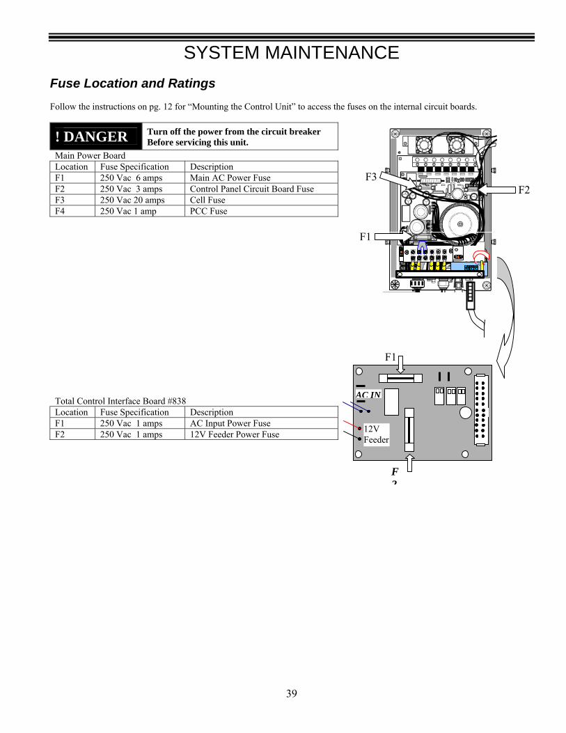
SYSTEM MAINTENANCE
39
Fuse Location and Ratings Follow the instructions on pg. 12 for “Mounting the Control Unit” to access the fuses on the internal circuit boards.
! DANGER
Turn off the power from the circuit breaker Before servicing this unit.
Main Power Board Location Fuse Specification Description F1 250 Vac 6 amps Main AC Power Fuse F2 250 Vac 3 amps Control Panel Circuit Board Fuse F3 250 Vac 20 amps Cell Fuse F4 250 Vac 1 amp PCC Fuse
Total Control Interface Board #838 Location Fuse Specification Description F1 250 Vac 1 amps AC Input Power Fuse F2 250 Vac 1 amps 12V Feeder Power Fuse
F1
F2
F1
F2F3
AC IN
12V Feeder
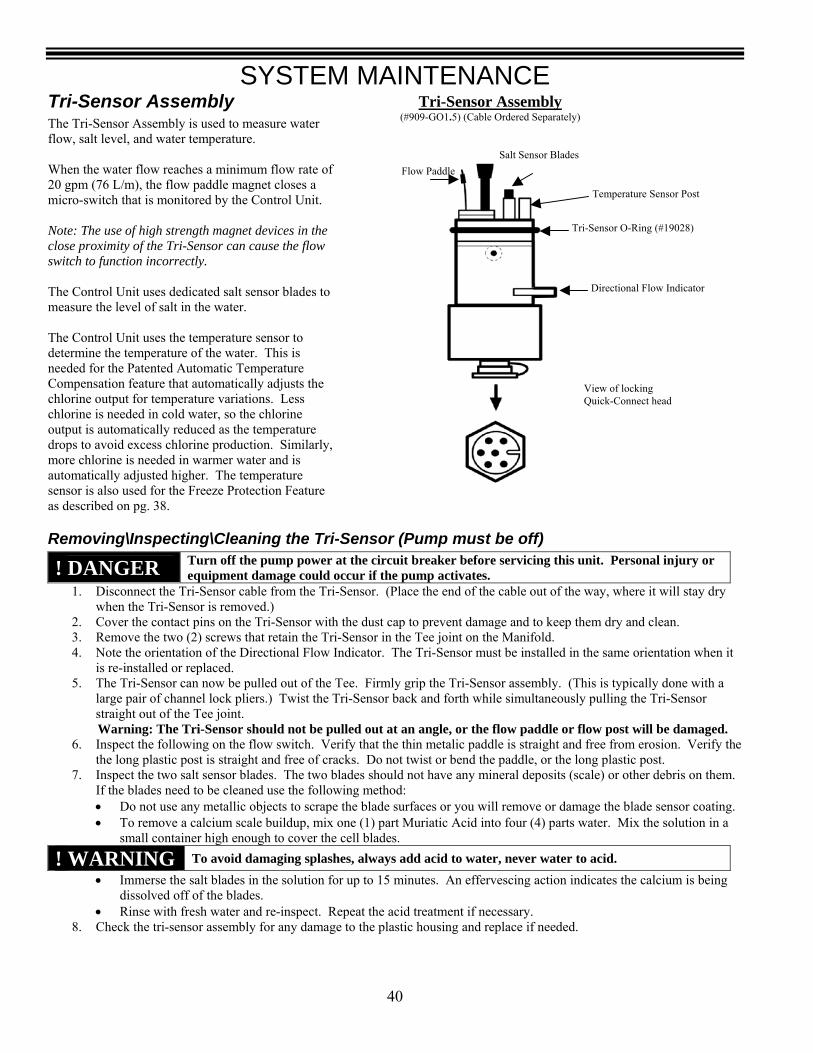
SYSTEM MAINTENANCE
40
Tri-Sensor Assembly (#909-GO1.5) (Cable Ordered Separately)
Temperature Sensor Post
Salt Sensor Blades
Directional Flow Indicator
Tri-Sensor O-Ring (#19028)
Flow Paddle
View of locking Quick-Connect head
Tri-Sensor Assembly The Tri-Sensor Assembly is used to measure water flow, salt level, and water temperature. When the water flow reaches a minimum flow rate of 20 gpm (76 L/m), the flow paddle magnet closes a micro-switch that is monitored by the Control Unit. Note: The use of high strength magnet devices in the close proximity of the Tri-Sensor can cause the flow switch to function incorrectly. The Control Unit uses dedicated salt sensor blades to measure the level of salt in the water. The Control Unit uses the temperature sensor to determine the temperature of the water. This is needed for the Patented Automatic Temperature Compensation feature that automatically adjusts the chlorine output for temperature variations. Less chlorine is needed in cold water, so the chlorine output is automatically reduced as the temperature drops to avoid excess chlorine production. Similarly, more chlorine is needed in warmer water and is automatically adjusted higher. The temperature sensor is also used for the Freeze Protection Feature as described on pg. 38.
Removing\Inspecting\Cleaning the Tri-Sensor (Pump must be off)
! DANGER Turn off the pump power at the circuit breaker before servicing this unit. Personal injury or equipment damage could occur if the pump activates.
1. Disconnect the Tri-Sensor cable from the Tri-Sensor. (Place the end of the cable out of the way, where it will stay dry when the Tri-Sensor is removed.)
2. Cover the contact pins on the Tri-Sensor with the dust cap to prevent damage and to keep them dry and clean. 3. Remove the two (2) screws that retain the Tri-Sensor in the Tee joint on the Manifold. 4. Note the orientation of the Directional Flow Indicator. The Tri-Sensor must be installed in the same orientation when it
is re-installed or replaced. 5. The Tri-Sensor can now be pulled out of the Tee. Firmly grip the Tri-Sensor assembly. (This is typically done with a
large pair of channel lock pliers.) Twist the Tri-Sensor back and forth while simultaneously pulling the Tri-Sensor straight out of the Tee joint.
Warning: The Tri-Sensor should not be pulled out at an angle, or the flow paddle or flow post will be damaged. 6. Inspect the following on the flow switch. Verify that the thin metalic paddle is straight and free from erosion. Verify the
the long plastic post is straight and free of cracks. Do not twist or bend the paddle, or the long plastic post. 7. Inspect the two salt sensor blades. The two blades should not have any mineral deposits (scale) or other debris on them.
If the blades need to be cleaned use the following method: • Do not use any metallic objects to scrape the blade surfaces or you will remove or damage the blade sensor coating. • To remove a calcium scale buildup, mix one (1) part Muriatic Acid into four (4) parts water. Mix the solution in a
small container high enough to cover the cell blades.
! WARNING To avoid damaging splashes, always add acid to water, never water to acid. • Immerse the salt blades in the solution for up to 15 minutes. An effervescing action indicates the calcium is being
dissolved off of the blades. • Rinse with fresh water and re-inspect. Repeat the acid treatment if necessary.
8. Check the tri-sensor assembly for any damage to the plastic housing and replace if needed.

SYSTEM MAINTENANCE
41
Testing the Flow Switch, Cleaning the Filter Screen, and Cleaning the Bypass Valve
The flow switch is an important safety protection device. When water flow has stopped, it is important that the SuperCell be automatically turned off to prevent damage to the cell or system. It is important to verify the safe and proper operation of the Tri-sensor’s Flow Switch protection device. The following procedure can be used to verify the proper operation of the flow switch or to flush debris from the Bypass Valve.
1. Turn off the pump. 2. Slightly loosen the union nut just below the cell on the side
of the manifold that does not contain the filter screen. 3. Completely loosen the manifold union nut that contains the
filter screen and pivot the manifold to gain access to the filter screen.
4. Remove the screen. Clean the screen if dirty. 5. If the screen was dirty, then the system may need to be
purged to remove excess debris. Leave the manifold off and run the pump for a few seconds until clear.
6. Wrap the strainer screen securely with a small piece of plastic wrap (saran wrap, food wrap or zip lock bag) as indicated in the diagram, place it back in the union.
7. Tighten the two unions that were loosened. 8. Reconnect the tri-sensor cord onto the tri-sensor. 9. Turn on the pump and the Pool Pilot. The plastic will stop water flow to the flow switch, which is part of the Tri-Sensor
that is located in the upper portion of the manifold. (All of the water will be forced through the Bypass Valve. This will normally flush out any small bits of debris that are trapped in the Bypass Valve.)
10. The Control Unit should detect a low water flow at the Tri-Sensor and activate the red Check System LED. The Control Unit will also display the message “Purifier Off! Check Flow”.
11. If the Control Unit did not display this warning, then check the Tri-Sensor cable connections and inspect and clean the Tri-Sensor as outlined in the previous section. If the warning message still does not appear, then turn the Pool Pilot off and contact the factory or your local dealer for assistance.
12. Turn the pump off. 13. Loosen the unions. 14. Remove the plastic wrap and replace the strainer screen. 15. Resume operation.
SuperCell The SuperCell may require removal for periodic visual inspections or for servicing when debris or calcium mineral deposits develop (the Control Unit displays the “Check System” light and the message, “Low Flow, Purifier OFF” or “Check Cell / Clean Cell”.)
Removal of the SuperCell: The SuperCell is installed with Unions on each end to allow quick and easy installation and removal.
• Turn off all power. • Detach the SuperCell cable from the
SuperCell. • Unscrew the unions at both ends of the
SuperCell. • Slide the SuperCell out of the Manifold
Assembly. SuperCell and Unions – (side view)
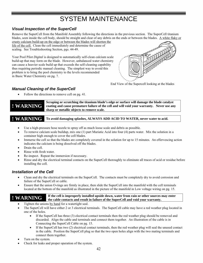
SYSTEM MAINTENANCE
42
Visual Inspection of the SuperCell Remove the SuperCell from the Manifold Assembly following the directions in the previous section. The SuperCell titanium blades, seen inside the cell body, should be straight and clear of any debris on the ends or between the blades. A white flaky or crusty calcium build-up on the edge or between the blades will shorten the life of the cell. Clean the cell immediately and determine the cause of scaling. See Troubleshooting Section, pgs. 44-49. Your Pool Pilot Digital is designed to automatically self-clean calcium scale build-up that may form on the blade. However, unbalanced water chemistry can cause a heavier scale build up that exceeds the self-cleaning capability thus requiring periodic manual cleaning. The simplest way to avoid this problem is to bring the pool chemistry to the levels recommended in Basic Water Chemistry on pg. 7.
Manual Cleaning of the SuperCell • Follow the directions to remove cell on pg. 41.
! WARNING Scraping or scratching the titanium blade’s edge or surface will damage the blade catalyst coating and cause premature failure of the cell and will void your warranty. Never use any sharp or metallic objects to remove scale.
• Use a high-pressure hose nozzle to spray off as much loose scale and debris as possible. • To remove calcium scale buildup, mix one (1) part Muriatic Acid into four (4) parts water. Mix the solution in a
container high enough to cover the cell blades. • Immerse the cell so that the blades are completely covered in the solution for up to 15 minutes. An effervescing action
indicates the calcium is being dissolved off the blades. • Drain the cell. • Rinse with fresh water. • Re-inspect. Repeat the immersion if necessary. • Rinse and dry the electrical terminal contacts on the SuperCell thoroughly to eliminate all traces of acid or residue before
installing the cell.
Installation of the Cell • Clean and dry the electrical terminals on the SuperCell. The contacts must be completely dry to avoid corrosion and
failure of the SuperCell or cable. • Ensure that the union O-rings are firmly in place, then slide the SuperCell into the manifold with the cell terminals
located at the bottom of the manifold as illustrated in the picture of the manifold in Low voltage wiring on pg. 15.
• Tighten the unions by hand for a watertight seal. • The SuperCell will have either 2 or 3 electrical terminals. The SuperCell cable may have a red weather plug located in
one of the holes. • If the SuperCell has three (3) electrical contact terminals then the red weather plug should be removed and
discarded. Align the cable and terminals and connect them together. An illustration of the cable is in Connecting the SuperCell Cable on pg. 15.
• If the SuperCell has two (2) electrical contact terminals, then the red weather plug will seal the unused contact in the cable. Position the SuperCell plug so that the two open holes align with the two mating terminals and connect them together.
• Turn on the system. • Check for leaks and proper operation of the system.
! WARNING To avoid damaging splashes, ALWAYS ADD ACID TO WATER, never water to acid.
! WARNING If the cell is improperly installed upside down, water from rain or other sources may enter the cable contacts and result in failure of the SuperCell and void your warranty.
End View of the Supercell looking at the blades
SYSTEM MAINTENANCE
43
Pool Chemistry Controller Sensor Maintenance Warning: The sensors are very delicate devices. They must be handled with care and protected at all times. Take care not to scratch or break the glass tip.
Helpful Hints: • Do not allow the sensor tip to dry out for more than one hour or damage to life or accuracy may occur. • The sensor tips must always be kept wet when in use or storage. • The sensors are threaded into the Flow Cell using Teflon tape. It is not recommended to use any “dope compound” or
glue to install the sensors. • Save the cap, box and packaging that the sensors came in for storage. • Do not over tighten the sensors into the flow cell as the flow cell housing may be damaged by this. • The sensors require 24 hours to stabilize when first installed. Any calibration should be done after this point.
Removal The ORP and pH sensors are connected to the #75001 Pool Chemistry Controller electronic processor unit using BNC connectors. These are designed to install and lock into position as shown on pg. 19. • Slide the BNC connector onto terminal and twist the lock knob clockwise to lock in place. • Twist the lock knob counterclockwise and slide down to remove. Similarly, unthread the sensors counterclockwise to remove from the flow cell, and clockwise to install into the flow cell. Take care to keep to keep the sensor tips wet unless cleaning.
Cleaning The sensor tips should be cleaned periodically using a degreasing dish detergent, such as Dawn, and a soft cloth or soft bristle brush. Follow these steps for cleaning:
1. Turn the Main circulation pump off 2. Remove the sensor from the Flow Cell 3. Clean the sensor tips with a soft cloth or brush and detergent 4. Rinse with fresh water, re-tape with Teflon tape and reinstall. 5. Allow 24 hours or operation to re-stabilize the sensor display.
Testing the Flow Cell
The flow switch contained in the Flow Cell is an important safety protection device. When water flow has stopped, it is important that the SuperCell be automatically turned off to prevent damage to the cell or system. It is important to verify the safe and proper operation of the Flow Cell’s Flow Switch protection device. The following procedure can be used to verify the proper operation of the flow switch.
1. Turn the Flow Cell inlet (left side) valve to the off position. 2. The Digital Control Unit should detect a low water flow at the Flow Cell and activate the red Check System LED. The
Digital Control Unit will also display the message “Purifier Off! Check Flow at sensors”. 3. If the Control Unit did not display this warning, then check the flow switch or cable connections for damage or loose
connections. 4. Remove the flow switch and using a continuity tester, check for continuity while manually activating the flow switch. 5. If the flow switch operates properly, service is needed on the Pool Chemistry Controller electronic circuit. 6. Contact Autopilot for service.

TROUBLESHOOTING GUIDE
44
Troubleshooting Guide Visit www.autopilot.com for the latest manual revisions, additional information and helpful troubleshooting tips. You can also reach our factory direct customer assistance by calling 800.922.6246 or 954.772.2255, by email at [email protected], or by FAX at 954.772.4070. Run the “View Setup” (pg. 31) and record the information displayed and have the information available prior to contacting Autopilot.
• Current measured salt level • Software version
The following will also be needed but may have been recorded by the installer in the front of your manual on pg. iii. • Date of installation • Control Unit model type should be # 75003 • Control Unit serial number • SuperCell model type • SuperCell serial number • Tri-Sensor serial number
Message on Display Problem Typical Solution Error! Purifier off Error! Acid off Check Flow
Chlorine generation has stopped due to insufficient water flow.
1. Turn the circulation pump on. 2. Turn the control valves to the correct position to allow water flow
through the manifold. 3. If a suction type vacuum cleaner is used, then clean if clogged. 4. Check and clean the skimmer basket. 5. Check and clean the pump basket. 6. Check and clean or backwash the main circulation filter. 7. Clean the manifold screen of trash or debris. Testing the Flow Switch,
Cleaning the Filter Screen, and Cleaning the Bypass Valve (see pg 41) 8. Verify that the Tri-Sensor cable is plugged in. Plug it in, using care to
orient it correctly before inserting it. (Warning: Read warning, instructions and see illustrations in Connecting the Tri-Sensor Cable on pg. 15)
9. Clean the SuperCell if plugged with debris or calcium scale? (See the sections under SuperCell on pgs. 41 - 42 for directions on removing, inspecting, and cleaning).
10. Check for air in the manifold by loosening the top union on the cell to see if air or water comes out. If air comes out then there may be a vacuum side leak or the pump may be undersized. Check for leak at pump basket O-ring, leaking valve or fitting.
11. If the pump is a 2-speed pump, is it on low speed? The low speed may not create enough flow for the manifold.
Purifier OFF! Add Salt xxx lbs
Chlorine generation has stopped because the salt level is below 1900 ppm, which is too low.
Add salt as indicated on the Digital display to bring the salt level up to 3000 ppm (3.0 g/l).
Warning! Add Salt xxx lbs
The salt level is between 2000-2400 ppm, which is low.
Add salt as indicated on the Digital display to bring the salt level up to 3000 ppm (3.0 g/l).
Purifier OFF! Add Salt xxx lbs or Warning! Add Salt xxx lbs
Added salt as indicated by the Pool Pilot, but salt level still shows low.
1. The pool volume has not been set up in the Installer Menu and is higher than the factory default of 15,000 gallons (56,000 liters).
2. The salt sensor in the Tri-Sensor may be dirty. 3. The Salt display may need to be calibrated.
No Error Displays
Salt level on display does not match pool store or salt test strip.
1. The test may have been faulty or the salt strips may be old or damaged. Have your salt level re-checked at your local pool store.
2. If the discrepancy is more than 400 ppm (4 mg/l), then contact AutoPilot Systems. If the Tri-Sensor salt blades are clean, then the salt sensor may need to be re-calibrated.
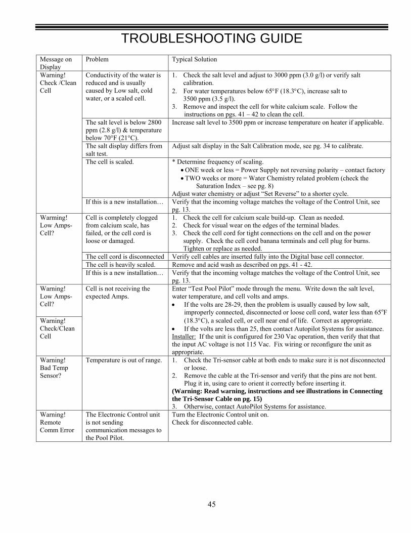
TROUBLESHOOTING GUIDE
45
Message on Display
Problem Typical Solution
Conductivity of the water is reduced and is usually caused by Low salt, cold water, or a scaled cell.
1. Check the salt level and adjust to 3000 ppm (3.0 g/l) or verify salt calibration.
2. For water temperatures below 65°F (18.3°C), increase salt to 3500 ppm (3.5 g/l). 3. Remove and inspect the cell for white calcium scale. Follow the
instructions on pgs. 41 – 42 to clean the cell. The salt level is below 2800 ppm (2.8 g/l) & temperature below 70°F (21°C).
Increase salt level to 3500 ppm or increase temperature on heater if applicable.
The salt display differs from salt test.
Adjust salt display in the Salt Calibration mode, see pg. 34 to calibrate.
The cell is scaled. * Determine frequency of scaling. • ONE week or less = Power Supply not reversing polarity – contact factory • TWO weeks or more = Water Chemistry related problem (check the
Saturation Index – see pg. 8) Adjust water chemistry or adjust “Set Reverse” to a shorter cycle.
Warning! Check /Clean Cell
If this is a new installation… Verify that the incoming voltage matches the voltage of the Control Unit, see pg. 13.
Cell is completely clogged from calcium scale, has failed, or the cell cord is loose or damaged.
1. Check the cell for calcium scale build-up. Clean as needed. 2. Check for visual wear on the edges of the terminal blades. 3. Check the cell cord for tight connections on the cell and on the power
supply. Check the cell cord banana terminals and cell plug for burns. Tighten or replace as needed.
The cell cord is disconnected Verify cell cables are inserted fully into the Digital base cell connector. The cell is heavily scaled. Remove and acid wash as described on pgs. 41 - 42.
Warming! Low Amps-Cell?
If this is a new installation… Verify that the incoming voltage matches the voltage of the Control Unit, see pg. 13.
Warning! Low Amps-Cell?
Warning! Check/Clean Cell
Cell is not receiving the expected Amps.
Enter “Test Pool Pilot” mode through the menu. Write down the salt level, water temperature, and cell volts and amps. • If the volts are 28-29, then the problem is usually caused by low salt,
improperly connected, disconnected or loose cell cord, water less than 65oF (18.3°C), a scaled cell, or cell near end of life. Correct as appropriate.
• If the volts are less than 25, then contact Autopilot Systems for assistance. Installer: If the unit is configured for 230 Vac operation, then verify that that the input AC voltage is not 115 Vac. Fix wiring or reconfigure the unit as appropriate.
Warning! Bad Temp Sensor?
Temperature is out of range. 1. Check the Tri-sensor cable at both ends to make sure it is not disconnected or loose.
2. Remove the cable at the Tri-sensor and verify that the pins are not bent. Plug it in, using care to orient it correctly before inserting it.
(Warning: Read warning, instructions and see illustrations in Connecting the Tri-Sensor Cable on pg. 15) 3. Otherwise, contact AutoPilot Systems for assistance.
Warning! Remote Comm Error
The Electronic Control unit is not sending communication messages to the Pool Pilot.
Turn the Electronic Control unit on. Check for disconnected cable.
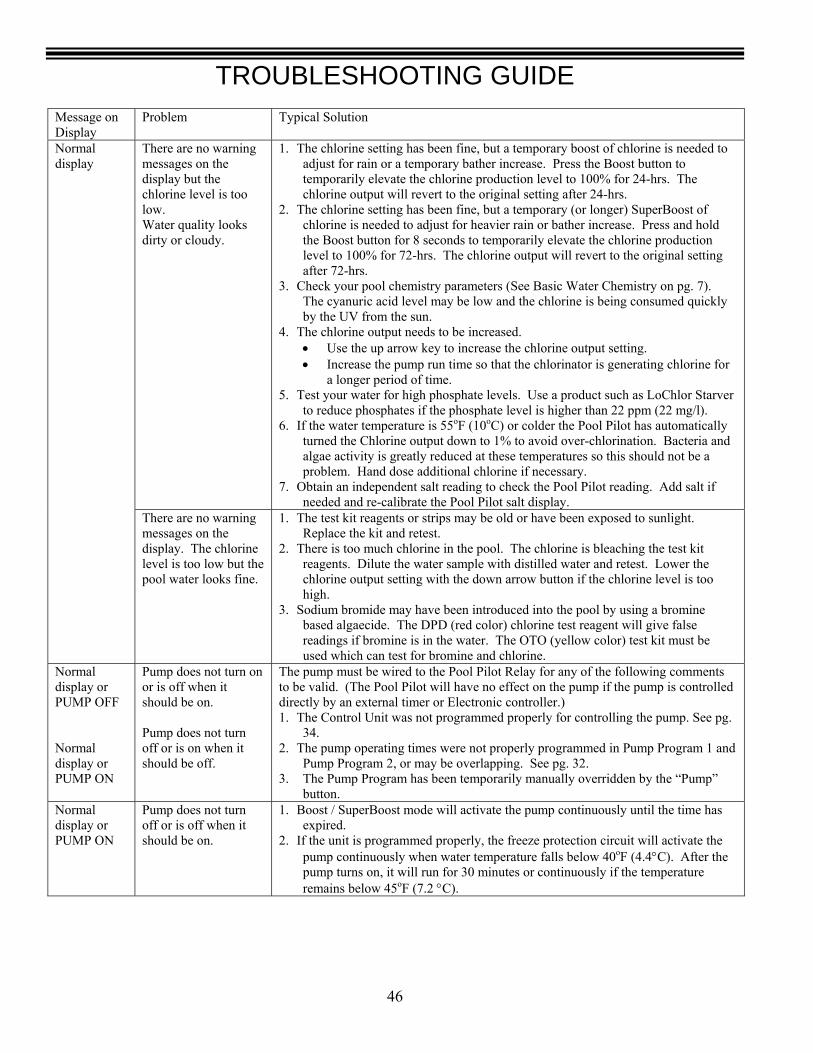
TROUBLESHOOTING GUIDE
46
Message on Display
Problem Typical Solution
There are no warning messages on the display but the chlorine level is too low. Water quality looks dirty or cloudy.
1. The chlorine setting has been fine, but a temporary boost of chlorine is needed to adjust for rain or a temporary bather increase. Press the Boost button to temporarily elevate the chlorine production level to 100% for 24-hrs. The chlorine output will revert to the original setting after 24-hrs.
2. The chlorine setting has been fine, but a temporary (or longer) SuperBoost of chlorine is needed to adjust for heavier rain or bather increase. Press and hold the Boost button for 8 seconds to temporarily elevate the chlorine production level to 100% for 72-hrs. The chlorine output will revert to the original setting after 72-hrs.
3. Check your pool chemistry parameters (See Basic Water Chemistry on pg. 7). The cyanuric acid level may be low and the chlorine is being consumed quickly by the UV from the sun.
4. The chlorine output needs to be increased. • Use the up arrow key to increase the chlorine output setting. • Increase the pump run time so that the chlorinator is generating chlorine for
a longer period of time. 5. Test your water for high phosphate levels. Use a product such as LoChlor Starver
to reduce phosphates if the phosphate level is higher than 22 ppm (22 mg/l). 6. If the water temperature is 55oF (10oC) or colder the Pool Pilot has automatically
turned the Chlorine output down to 1% to avoid over-chlorination. Bacteria and algae activity is greatly reduced at these temperatures so this should not be a problem. Hand dose additional chlorine if necessary.
7. Obtain an independent salt reading to check the Pool Pilot reading. Add salt if needed and re-calibrate the Pool Pilot salt display.
Normal display
There are no warning messages on the display. The chlorine level is too low but the pool water looks fine.
1. The test kit reagents or strips may be old or have been exposed to sunlight. Replace the kit and retest.
2. There is too much chlorine in the pool. The chlorine is bleaching the test kit reagents. Dilute the water sample with distilled water and retest. Lower the chlorine output setting with the down arrow button if the chlorine level is too high.
3. Sodium bromide may have been introduced into the pool by using a bromine based algaecide. The DPD (red color) chlorine test reagent will give false readings if bromine is in the water. The OTO (yellow color) test kit must be used which can test for bromine and chlorine.
Normal display or PUMP OFF Normal display or PUMP ON
Pump does not turn on or is off when it should be on. Pump does not turn off or is on when it should be off.
The pump must be wired to the Pool Pilot Relay for any of the following comments to be valid. (The Pool Pilot will have no effect on the pump if the pump is controlled directly by an external timer or Electronic controller.) 1. The Control Unit was not programmed properly for controlling the pump. See pg.
34. 2. The pump operating times were not properly programmed in Pump Program 1 and
Pump Program 2, or may be overlapping. See pg. 32. 3. The Pump Program has been temporarily manually overridden by the “Pump”
button. Normal display or PUMP ON
Pump does not turn off or is off when it should be on.
1. Boost / SuperBoost mode will activate the pump continuously until the time has expired.
2. If the unit is programmed properly, the freeze protection circuit will activate the pump continuously when water temperature falls below 40oF (4.4°C). After the pump turns on, it will run for 30 minutes or continuously if the temperature remains below 45oF (7.2 °C).
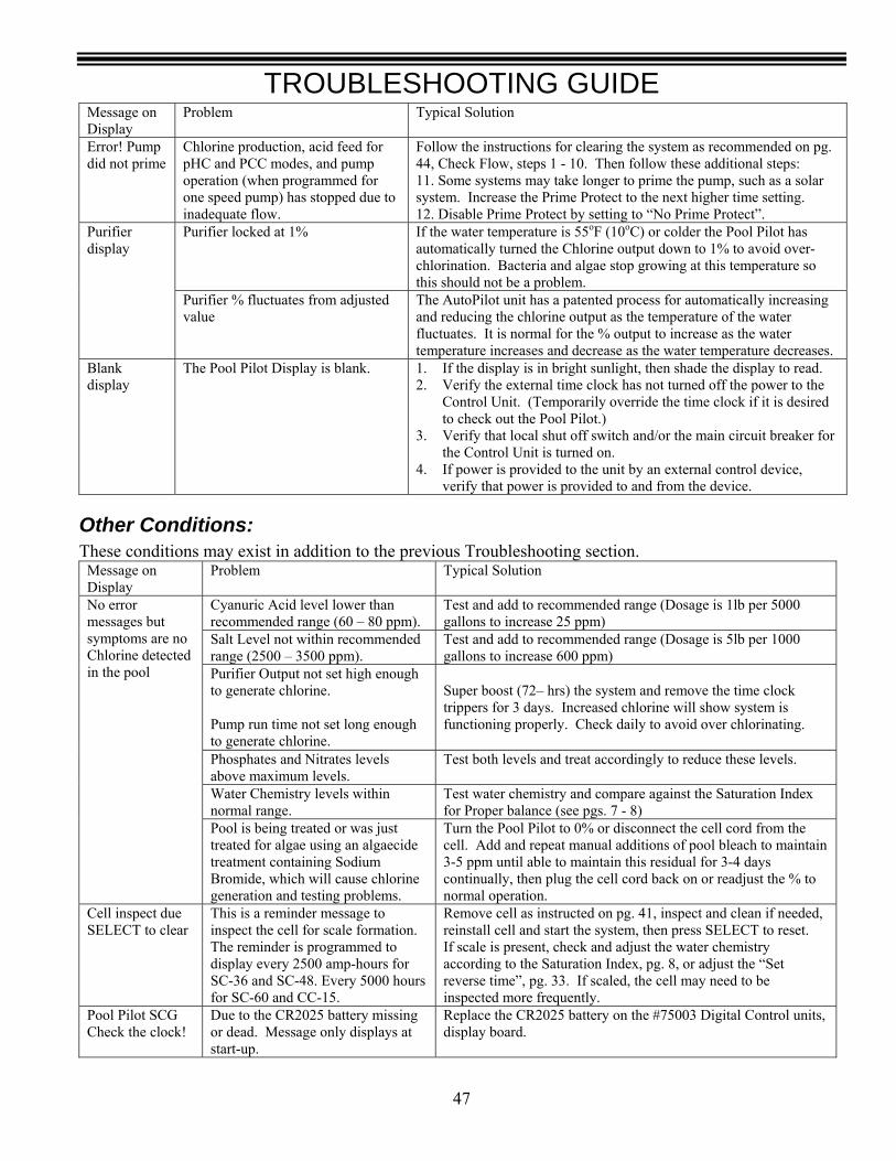
TROUBLESHOOTING GUIDE
47
Message on Display
Problem Typical Solution
Error! Pump did not prime
Chlorine production, acid feed for pHC and PCC modes, and pump operation (when programmed for one speed pump) has stopped due to inadequate flow.
Follow the instructions for clearing the system as recommended on pg. 44, Check Flow, steps 1 - 10. Then follow these additional steps: 11. Some systems may take longer to prime the pump, such as a solar system. Increase the Prime Protect to the next higher time setting. 12. Disable Prime Protect by setting to “No Prime Protect”.
Purifier locked at 1% If the water temperature is 55oF (10oC) or colder the Pool Pilot has automatically turned the Chlorine output down to 1% to avoid over-chlorination. Bacteria and algae stop growing at this temperature so this should not be a problem.
Purifier display
Purifier % fluctuates from adjusted value
The AutoPilot unit has a patented process for automatically increasing and reducing the chlorine output as the temperature of the water fluctuates. It is normal for the % output to increase as the water temperature increases and decrease as the water temperature decreases.
Blank display
The Pool Pilot Display is blank. 1. If the display is in bright sunlight, then shade the display to read. 2. Verify the external time clock has not turned off the power to the
Control Unit. (Temporarily override the time clock if it is desired to check out the Pool Pilot.)
3. Verify that local shut off switch and/or the main circuit breaker for the Control Unit is turned on.
4. If power is provided to the unit by an external control device, verify that power is provided to and from the device.
Other Conditions: These conditions may exist in addition to the previous Troubleshooting section.
Message on Display
Problem Typical Solution
Cyanuric Acid level lower than recommended range (60 – 80 ppm).
Test and add to recommended range (Dosage is 1lb per 5000 gallons to increase 25 ppm)
Salt Level not within recommended range (2500 – 3500 ppm).
Test and add to recommended range (Dosage is 5lb per 1000 gallons to increase 600 ppm)
Purifier Output not set high enough to generate chlorine. Pump run time not set long enough to generate chlorine.
Super boost (72– hrs) the system and remove the time clock trippers for 3 days. Increased chlorine will show system is functioning properly. Check daily to avoid over chlorinating.
Phosphates and Nitrates levels above maximum levels.
Test both levels and treat accordingly to reduce these levels.
Water Chemistry levels within normal range.
Test water chemistry and compare against the Saturation Index for Proper balance (see pgs. 7 - 8)
No error messages but symptoms are no Chlorine detected in the pool
Pool is being treated or was just treated for algae using an algaecide treatment containing Sodium Bromide, which will cause chlorine generation and testing problems.
Turn the Pool Pilot to 0% or disconnect the cell cord from the cell. Add and repeat manual additions of pool bleach to maintain 3-5 ppm until able to maintain this residual for 3-4 days continually, then plug the cell cord back on or readjust the % to normal operation.
Cell inspect due SELECT to clear
This is a reminder message to inspect the cell for scale formation. The reminder is programmed to display every 2500 amp-hours for SC-36 and SC-48. Every 5000 hours for SC-60 and CC-15.
Remove cell as instructed on pg. 41, inspect and clean if needed, reinstall cell and start the system, then press SELECT to reset. If scale is present, check and adjust the water chemistry according to the Saturation Index, pg. 8, or adjust the “Set reverse time”, pg. 33. If scaled, the cell may need to be inspected more frequently.
Pool Pilot SCG Check the clock!
Due to the CR2025 battery missing or dead. Message only displays at start-up.
Replace the CR2025 battery on the #75003 Digital Control units, display board.

TROUBLESHOOTING GUIDE
48
Total Control and pH Control Displays Message on
Display Problem Typical Solution
Warning! Replace sensors
The pH sensor could not be calibrated to match the results of a reliable pH test kit. The pH sensor reading is off by more than its calibration limit of ±2.0 pH units.
Check and clean sensors, then calibrate. If the sensor will not calibrate after cleaning, replace both the pH and ORP sensors.
Warning! pH low 6.50
pH is below a user programmable minimum pH between 6.5 and 8.0. Low pH may result in a low chlorine level. Once the pH is adjusted, the ORP may also need to be adjusted to compensate. The default pH minimum is 7.0
Add chemicals to increase pH measurement to the desired pH level. Check and clean pH sensor, then calibrate as needed. Adjust pH min higher if set too low.
Warning! pH high 8.50
pH is above a user programmable maximum. pH between 6.5 and 8.0. The system will not generate chlorine or feed acid while the pH is above the pH max setting, but will make fine adjustments when below. The default pH maximum is 8.0
Add chemicals to decrease pH measurement to the desired pH level. Check and clean pH sensor, then calibrate as needed. Check acid feed tank for sufficient acid and water. Adjust pH max lower if set too high. Check the pH acid pump for proper operation or leaks by activating prime acid pump, pg. 35.
ORP disabled The user has programmed the system to disable the SuperCell operation. Manual addition of chlorine is required until enabled.
Enable ORP control, pg. 36.
Acid disabled The user has disabled the acid pump. Manual addition of pH adjuster is required until enabled.
Enable pH control, pg. 35

TROUBLESHOOTING GUIDE
49
Total Control Error Displays Message on Display Problem Typical Solution
Error! Purifier off Error! Acid off Check flow at sensors
Flow at sensors is not detected. Chlorine and acid are not fed under these conditions, until corrected.
Ensure sufficient flow to the flow cell, pg. 44. Open the inlet and outlet valves to the flow cell. Valve handles should be vertical. Verify that the sample water valve is closed, valve handle horizontal.
Error! Purifier off Error! Acid off Check ORP sensor
The measured ORP is out of range and may be caused when the sensor is not properly connected or if the sensor is past its useful life. Out of range ORP measurement is below 100 mv or above 900 mv. Chlorine and acid are not fed under these conditions, until corrected.
Check and secure ORP connections. Replace ORP sensor.
Error! Purifier off Error! Acid off ORP overfeed
The measured ORP has not reached its set point within a user programmable time, between No ORP Overfeed to 120 minutes. The factory setting is “No ORP overfeed”. Chlorine and acid are not fed under these conditions, until corrected.
Clear the ORP overfeed warning by programming ORP overfeed OFF and back ON, pg. 36. Check the operation of the purifier mode by ensuring proper salt, pH, and stabilizer levels. Check and clean ORP sensor. Check “Other conditions” on pg. 47.
Error! Purifier off Error! Acid off Check pH sensor
The measured pH is out of range and may be caused when the sensor is not properly connected or if the sensor is past its useful life. Out of range pH measurement is below 4.0 or above 9.9. Chlorine and acid are not fed under these conditions, until corrected.
Check and secure pH connections. Replace pH sensor.
Error! Purifier off Error! Acid off pH overfeed
The measured pH has not reached its set point within a user programmable time; between No pH overfeed to 120 minutes. The factory setting is “No pH overfeed”. Chlorine and acid are not fed under these conditions, until corrected.
Clear the pH Overfeed warning by Check the programming pH overfeed OFF and back ON, pg. 36. Check operation of the acid feed pump by performing the “Prime acid pump”, see pg. 35. Check and clean pH sensor. Check acid tank for proper levels of acid solution.
Error! Purify off Error! Acid off Check OpEC
The controller is not able to communicate with the OpEC Unit or if the software version is incompatible.
Verify proper connection of the Interface wire between #75001 TC and #75003 Digital units. Contact the Factory for service.
Check Serial EEPROM
The controller is not able to communicate with the Total Control Circuit or if the software version is incompatible.
Verify proper connection of the Interface wire between #75001 TC and #75003 Digital units. Contact the Factory for service.