Embed Size (px)
Citation preview
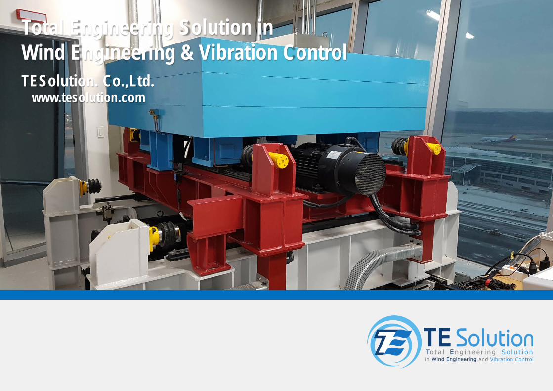
Total Engineering Solution inWind Engineering & Vibration ControlTESolution. Co.,Ltd.
www.tesolution.com
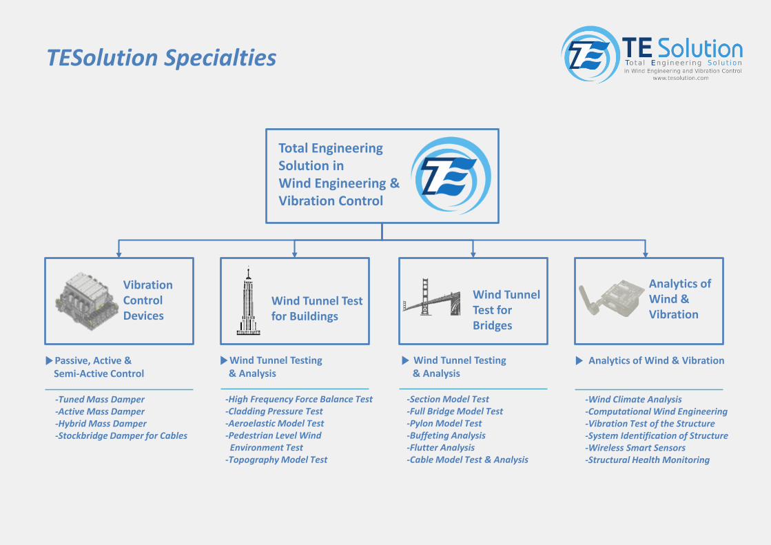
TESolution Specialties
Total EngineeringSolution in Wind Engineering & Vibration Control
VibrationControlDevices
▶Passive, Active &Semi-Active Control
-Tuned Mass Damper-Active Mass Damper-Hybrid Mass Damper-Stockbridge Damper for Cables
▶Wind Tunnel Testing & Analysis
-High Frequency Force Balance Test-Cladding Pressure Test-Aeroelastic Model Test-Pedestrian Level Wind
Environment Test-Topography Model Test
▶Wind Tunnel Testing & Analysis
-Section Model Test-Full Bridge Model Test-Pylon Model Test-Buffeting Analysis-Flutter Analysis-Cable Model Test & Analysis
Analytics of Wind & Vibration
▶ Analytics of Wind & Vibration
-Wind Climate Analysis-Computational Wind Engineering-Vibration Test of the Structure -System Identification of Structure-Wireless Smart Sensors-Structural Health Monitoring
Wind Tunnel Test for Buildings
Wind Tunnel Test forBridges
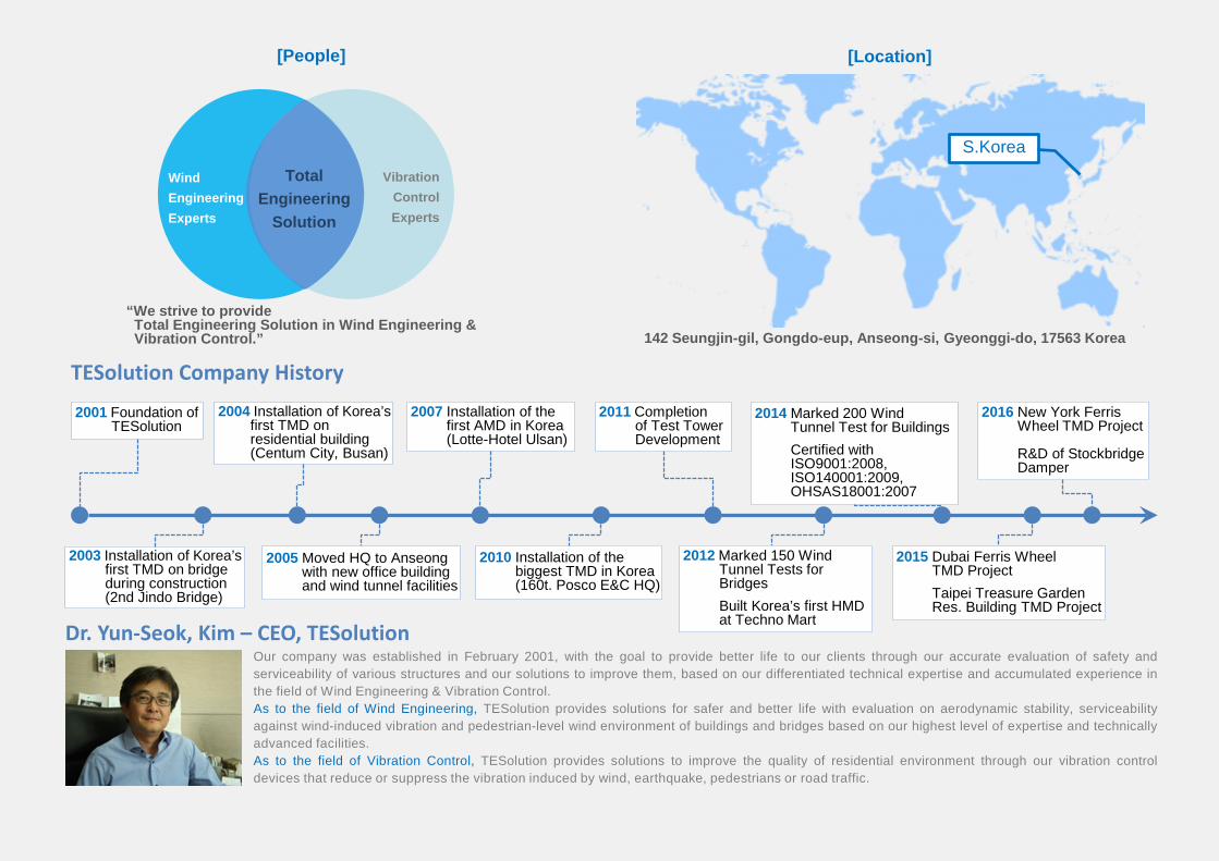
Dr. Yun-Seok, Kim – CEO, TESolutionOur company was established in February 2001, with the goal to provide better life to our clients through our accurate evaluation of safety andserviceability of various structures and our solutions to improve them, based on our differentiated technical expertise and accumulated experience inthe field of Wind Engineering & Vibration Control.As to the field of Wind Engineering, TESolution provides solutions for safer and better life with evaluation on aerodynamic stability, serviceabilityagainst wind-induced vibration and pedestrian-level wind environment of buildings and bridges based on our highest level of expertise and technicallyadvanced facilities.As to the field of Vibration Control, TESolution provides solutions to improve the quality of residential environment through our vibration controldevices that reduce or suppress the vibration induced by wind, earthquake, pedestrians or road traffic.
[Location]
S.Korea
142 Seungjin-gil, Gongdo-eup, Anseong-si, Gyeonggi-do, 17563 Korea
[People]
TESolution Company History
2001 Foundation of TESolution
2004 Installation of Korea’s first TMD onresidential building(Centum City, Busan)
2010 Installation of the biggest TMD in Korea (160t. Posco E&C HQ)
2007 Installation of the first AMD in Korea (Lotte-Hotel Ulsan)
2011 Completionof Test Tower Development
2014 Marked 200 Wind Tunnel Test for BuildingsCertified with ISO9001:2008, ISO140001:2009, OHSAS18001:2007
2015 Dubai Ferris Wheel TMD ProjectTaipei Treasure Garden Res. Building TMD Project
2003 Installation of Korea’s first TMD on bridge during construction(2nd Jindo Bridge)
2005 Moved HQ to Anseongwith new office building and wind tunnel facilities
TotalEngineering
Solution
WindEngineeringExperts
VibrationControlExperts
“We strive to provideTotal Engineering Solution in Wind Engineering &Vibration Control.”
2016 New York Ferris Wheel TMD Project
R&D of Stockbridge Damper
2012 Marked 150 Wind Tunnel Tests for BridgesBuilt Korea’s first HMD at Techno Mart
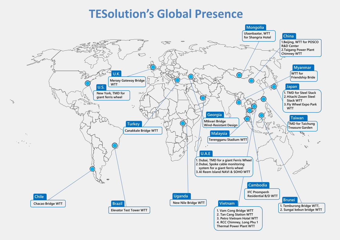
TESolution’s Global PresenceUlaanbaatar, WTT for Shangria Hotel China
Japan
BruneiVietnam 1. Temburong Bridge WTT,
2. Sungai kebun bridge WTT1. Vam Cong Bridge WTT2. Tan Cang Station WTT3. Petro Vietnam Hotel WTT4. RCC Chimney, Long Phu 1 Thermal Power Plant WTT
1. TMD for Steel Stack2.Hitachi Zosen Steel
Stack WTT3.Fly Wheel Expo Park
WTT
Chile
U.A.E
UgandaNew Nile Bridge WTT
Elevator Test Tower WTT
Brazil
U.S.New York, TMD for giant ferris wheel
Mongolia
Myanmar
Malaysia
TurkeyTaiwan
Cambodia
WTT for Friendship Bride
TMD for Taichung Treasure Garden
Canakkale Bridge WTT
GeorgiaMtkvari Bridge Wind-Resistant Design
Mersey Gateway BridgeWTT
U.K.
1.Beijing, WTT for POSCO R&D Center2.Taigang Power Plant Chimney WTT
Terengganu Stadium WTT
IFC PnompenhResidential B/D WTT
1. Dubai, TMD for a giant Ferris Wheel2.Dubai, Spoke cable monitoring
system for a giant ferris wheel3.Al Reem Island NAVI & SOHO WTT
Chacao Bridge WTT
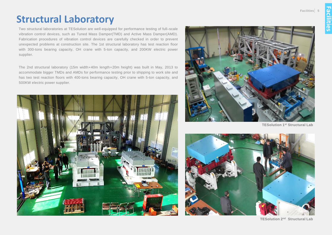
Two structural laboratories at TESolution are well-equipped for performance testing of full–scalevibration control devices, such as Tuned Mass Damper(TMD) and Active Mass Damper(AMD).Fabrication procedures of vibration control devices are carefully checked in order to preventunexpected problems at construction site. The 1st structural laboratory has test reaction floorwith 300-tons bearing capacity, OH crane with 5-ton capacity, and 200KW electric powersupplier.
The 2nd structural laboratory (15m width×40m length×20m height) was built in May, 2013 toaccommodate bigger TMDs and AMDs for performance testing prior to shipping to work site andhas two test reaction floors with 400-tons bearing capacity, OH crane with 5-ton capacity, and500KW electric power supplier.
Structural Laboratory
TESolution 1st Structural Lab
TESolution 2nd Structural Lab
Facilities 5
Facilities
The test tower is a 5 story (20m height) tall steel structure that is a unique test facility for variousvibration control devices. This tower is mainly used to conduct performance test of newly developedvibration control devices such as AMD. In the excitation room, a vibration exciter simulates thevibration of the tower. In the control room, the control device stationed inside detects the vibration andcounteracts in order to reduce the vibration of the tower.
Control Room
Excitation RoomComposition Excitation Room
Heights Level 4 (16m Height)
Description
vibration exciter that can excite the test tower in various ways is installed inside.
Composition Control Room
Heights Level 5 (20m Height)
Description
Performance testing for active type vibration control devices under development.
Faci
litie
s
Test Tower
Facilities 7
Category Boundary Layer Wind Tunnel
Type Open-circuit(Suction)
Dimension 8.0m(width) ⅹ 2.5m(height) ⅹ 23.2m(length)
Wind Speed 0.3 ∼ 11.0m/s
Uniformity Turbulence Intensity of 0.5% , Wind Velocity ±1.0% (for smooth flow)
Blower 3 x 132KW
Specification
1.TEST SECTION2.SUCTION TYPE MULTI-FAN3.INLET OF SETTLING CHAMBER4.TURNTABLE SYSTEM5.TRAVERSE SYSTEM6.OUTLINE OF WIND TUNNEL
3
1
24
5 6
Boundary Layer Wind Tunnel
Facilities
CONTRACTION BODY
TURN TABLE
SPACE DUCTBLOWER TRANSVERSER TEST SECTIONBELL MOUTH
The boundary layer wind tunnel is a facility designed to simulate the air flow aroundstructures for variety of aerodynamics studies with ground roughness and height intoconsideration.
This wind tunnel is well suited for model studies of air flow over various structures, fullmodel of long-span bridges, stand-alone pylon, and cable structures, as well astopographic feature.
Bridge cross-section model test is conducted to investigate the aerodynamic responsecharacteristics of the bridge section.
TESoluotion currently operates two different sizes of 2D wind tunnel that are primarilyused to check the aerodynamic stability of long-span bridge, such as vortex-inducedvibration, flutter, and galloping phenomena with bridge section model.
Testing rig for 2D wind tunnel consists of various equipment such as spring-supportsystem, active turbulence generator, and forced oscillator.
Wind Tunnel for Section Model
TESolution Mid-size 2d Wind Tunnel
TESolution Small-size 2d Wind Tunnel
SMALL-SIZE 2D WIND TUNNEL
MID-SIZE 2D WIND TUNNEL
Type Test Section Dimension Wind Speed
Eiffel-type 1 m (W) x 1.5 m (H) x 6 m (L) 0.3m/s ~ 21.0m/s
Type Test Section Dimension Wind Speed
Eiffel-type 1.5 m (W) x 2.0 m (H) x 7.5 m (L) 0.3m/s ~ 25.0 m/s
Faci
litie
s
LOAD CELL SPRING SUPPORT SPACE DUCT BLOWER
SPACE DUCT BLOWERSPRING SUPPORTFORCED OSCILLATOR
Vibration Control Devices
Sliding-type Tuned Mass Damper Active Mass Damper
•Basic/Detail design : Determination of dimension, types, and specifications of vibration control devices, drawing works•Fabrication/ Performance test at TESolution : Friction/vibration tests•Vibration Measurement: Measurement of structural frequency, damping ratio, and estimation of mode shape.• Installation supervision/ Performance test at construction site : Frequency tuning and verification of required control performance• Maintenance : Periodically check the TMD’s control performance and durability of the key components
Vibration Control Devices 9
Pendulum-type Tuned Mass Damper
: :
Vibration Control
With accumulated R&D effort on top of the highest expertise in the field, TESolution has been providing tailored solutionsof vibration control to various types of structures, including skyscrapers, long-span bridges, footbridges, cable cars, airtraffic control towers, etc.
Especially as the structures are becoming taller, lighter, and longer with the advancement of the constructiontechnology, they are also becoming more vulnerable to vibrations induced by dynamic loads such as wind and traffic.
For the serviceability of skyscrapers, structural safety of bridges, or pedestrian comfort of footbridges, TESolution's vibrationcontrol device such as Tuned Mass Damper(TMD), Active Mass Damper(AMD), and Hybrid Mass Damper(HMD) can be thesolution to vibration control .
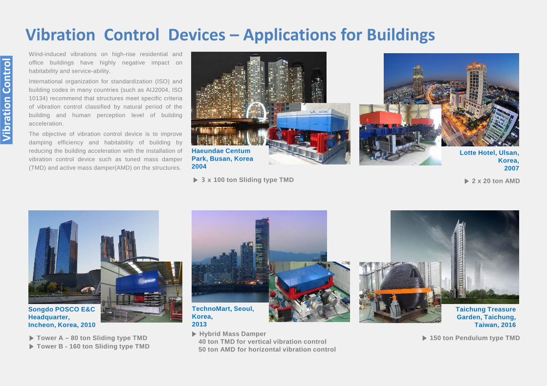
Wind-induced vibrations on high-rise residential andoffice buildings have highly negative impact onhabitability and service-ability.
International organization for standardization (ISO) andbuilding codes in many countries (such as AIJ2004, ISO10134) recommend that structures meet specific criteriaof vibration control classified by natural period of thebuilding and human perception level of buildingacceleration.
The objective of vibration control device is to improvedamping efficiency and habitability of building byreducing the building acceleration with the installation ofvibration control device such as tuned mass damper(TMD) and active mass damper(AMD) on the structures.
Haeundae Centum Park, Busan, Korea2004
Lotte Hotel, Ulsan, Korea,
2007
▶ 2 x 20 ton AMD▶ 3 x 100 ton Sliding type TMD
▶ Hybrid Mass Damper40 ton TMD for vertical vibration control50 ton AMD for horizontal vibration control
Songdo POSCO E&C Headquarter, Incheon, Korea, 2010
▶ Tower A – 80 ton Sliding type TMD▶ Tower B - 160 ton Sliding type TMD
▶ 150 ton Pendulum type TMD
Taichung Treasure Garden, Taichung,
Taiwan, 2016
TechnoMart, Seoul,Korea,2013
Vibration Control Devices – Applications for Buildings
Vibr
atio
n Co
ntro
l
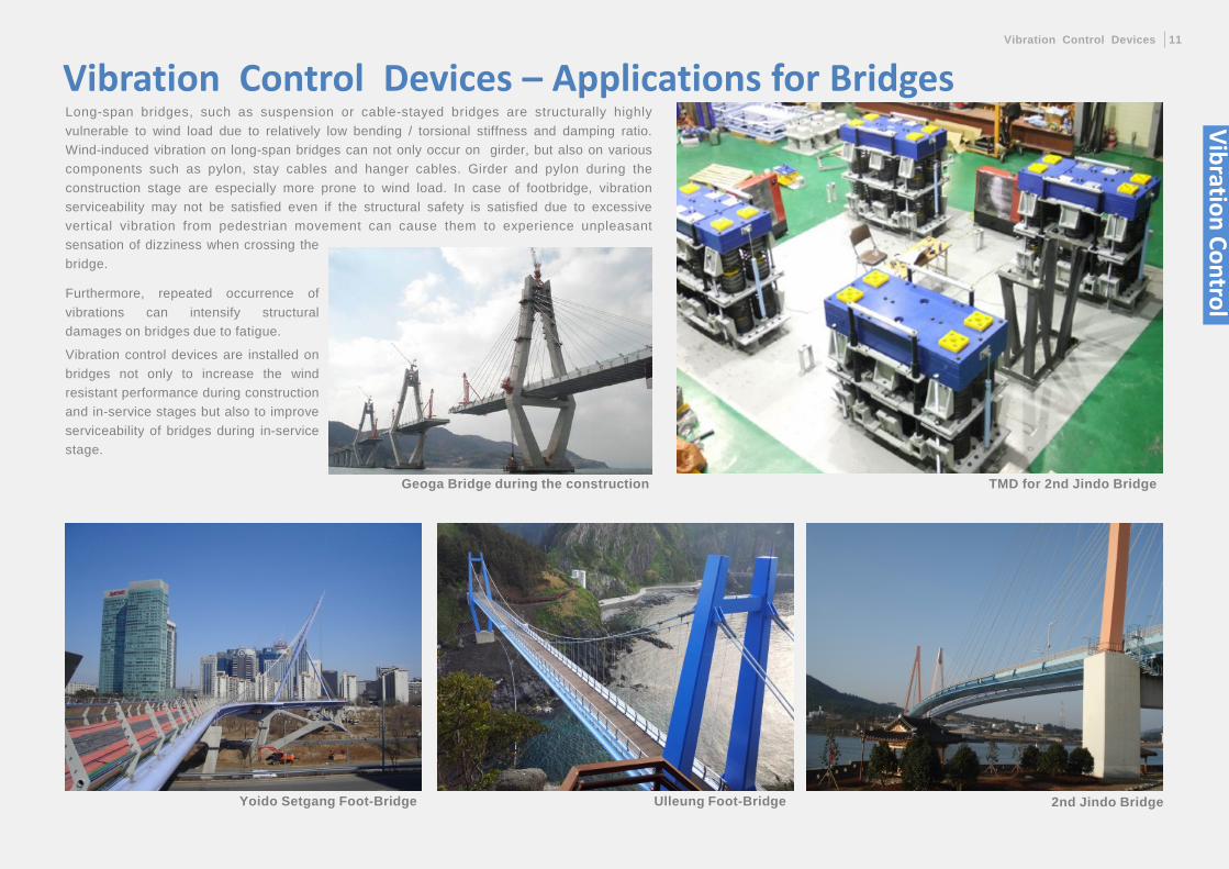
Yoido Setgang Foot-Bridge Ulleung Foot-Bridge 2nd Jindo Bridge
Vibration Control Devices – Applications for Bridges
TMD for 2nd Jindo Bridge
Long-span bridges, such as suspension or cable-stayed bridges are structurally highlyvulnerable to wind load due to relatively low bending / torsional stiffness and damping ratio.Wind-induced vibration on long-span bridges can not only occur on girder, but also on variouscomponents such as pylon, stay cables and hanger cables. Girder and pylon during theconstruction stage are especially more prone to wind load. In case of footbridge, vibrationserviceability may not be satisfied even if the structural safety is satisfied due to excessivevertical vibration from pedestrian movement can cause them to experience unpleasant
Furthermore, repeated occurrence ofvibrations can intensify structuraldamages on bridges due to fatigue.
Vibration control devices are installed onbridges not only to increase the windresistant performance during constructionand in-service stages but also to improveserviceability of bridges during in-servicestage.
sensation of dizziness when crossing thebridge.
Geoga Bridge during the construction
Vibration Control Devices 11
Vibration Control
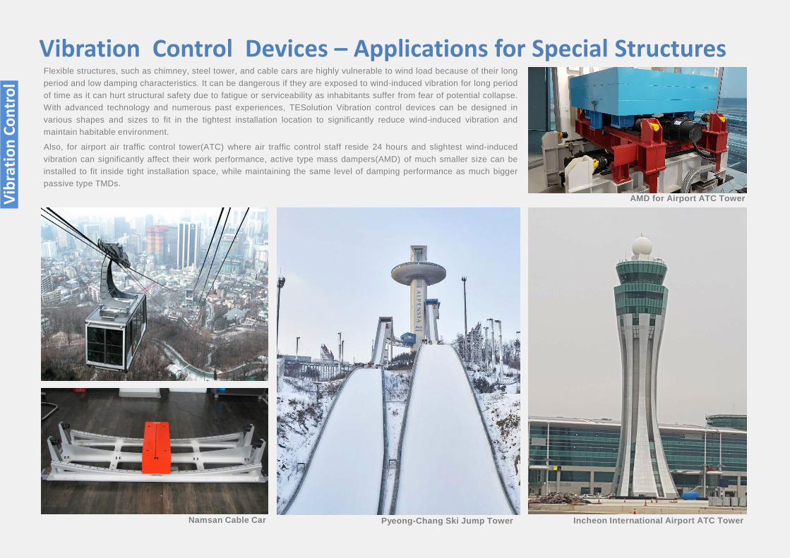
Flexible structures, such as chimney, steel tower, and cable cars are highly vulnerable to wind load because of their longperiod and low damping characteristics. It can be dangerous if they are exposed to wind-induced vibration for long periodof time as it can hurt structural safety due to fatigue or serviceability as inhabitants suffer from fear of potential collapse.With advanced technology and numerous past experiences, TESolution Vibration control devices can be designed invarious shapes and sizes to fit in the tightest installation location to significantly reduce wind-induced vibration andmaintain habitable environment.
Also, for airport air traffic control tower(ATC) where air traffic control staff reside 24 hours and slightest wind-inducedvibration can significantly affect their work performance, active type mass dampers(AMD) of much smaller size can beinstalled to fit inside tight installation space, while maintaining the same level of damping performance as much biggerpassive type TMDs.
Namsan Cable Car Pyeong-Chang Ski Jump Tower Incheon International Airport ATC Tower
Vibration Control Devices – Applications for Special Structures
AMD for Airport ATC TowerVibr
atio
n Co
ntro
l
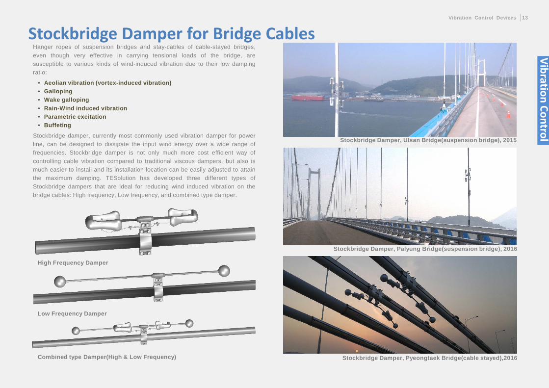
Stockbridge Damper, Pyeongtaek Bridge(cable stayed),2016
Stockbridge Damper, Ulsan Bridge(suspension bridge), 2015
Stockbridge Damper, Palyung Bridge(suspension bridge), 2016
Stockbridge Damper for Bridge CablesHanger ropes of suspension bridges and stay-cables of cable-stayed bridges,even though very effective in carrying tensional loads of the bridge, aresusceptible to various kinds of wind-induced vibration due to their low dampingratio:
• Aeolian vibration (vortex-induced vibration)• Galloping• Wake galloping• Rain-Wind induced vibration• Parametric excitation• Buffeting
Stockbridge damper, currently most commonly used vibration damper for powerline, can be designed to dissipate the input wind energy over a wide range offrequencies. Stockbridge damper is not only much more cost efficient way ofcontrolling cable vibration compared to traditional viscous dampers, but also ismuch easier to install and its installation location can be easily adjusted to attainthe maximum damping. TESolution has developed three different types ofStockbridge dampers that are ideal for reducing wind induced vibration on thebridge cables: High frequency, Low frequency, and combined type damper.
High Frequency Damper
Low Frequency Damper
Combined type Damper(High & Low Frequency)
Vibration ControlVibration Control Devices 13
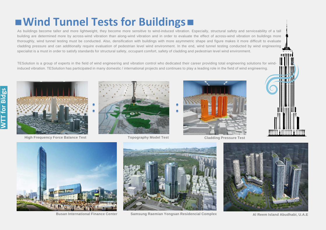
TESolution is a group of experts in the field of wind engineering and vibration control who dedicated their career providing total engineering solutions for wind-induced vibration. TESolution has participated in many domestic / international projects and continues to play a leading role in the field of wind engineering.
As buildings become taller and more lightweight, they become more sensitive to wind-induced vibration. Especially, structural safety and serviceability of a tallbuilding are determined more by across-wind vibration than along-wind vibration and in order to evaluate the effect of across-wind vibration on buildings morethoroughly, wind tunnel testing must be conducted. Also, densification with buildings with more asymmetric shape and figure makes it more difficult to evaluatecladding pressure and can additionally require evaluation of pedestrian level wind environment. In the end, wind tunnel testing conducted by wind engineeringspecialist is a must in order to satisfy standards for structural safety, occupant comfort, safety of cladding and pedestrian level wind environment.
Busan International Finance Center Samsung Raemian Yongsan Residencial Complex Al Reem Island Abudhabi, U.A.E
High Frequency Force Balance Test Cladding Pressure TestTopography Model Test
Wind Tunnel Tests for Buildings
: :
WTT
for B
ldgs
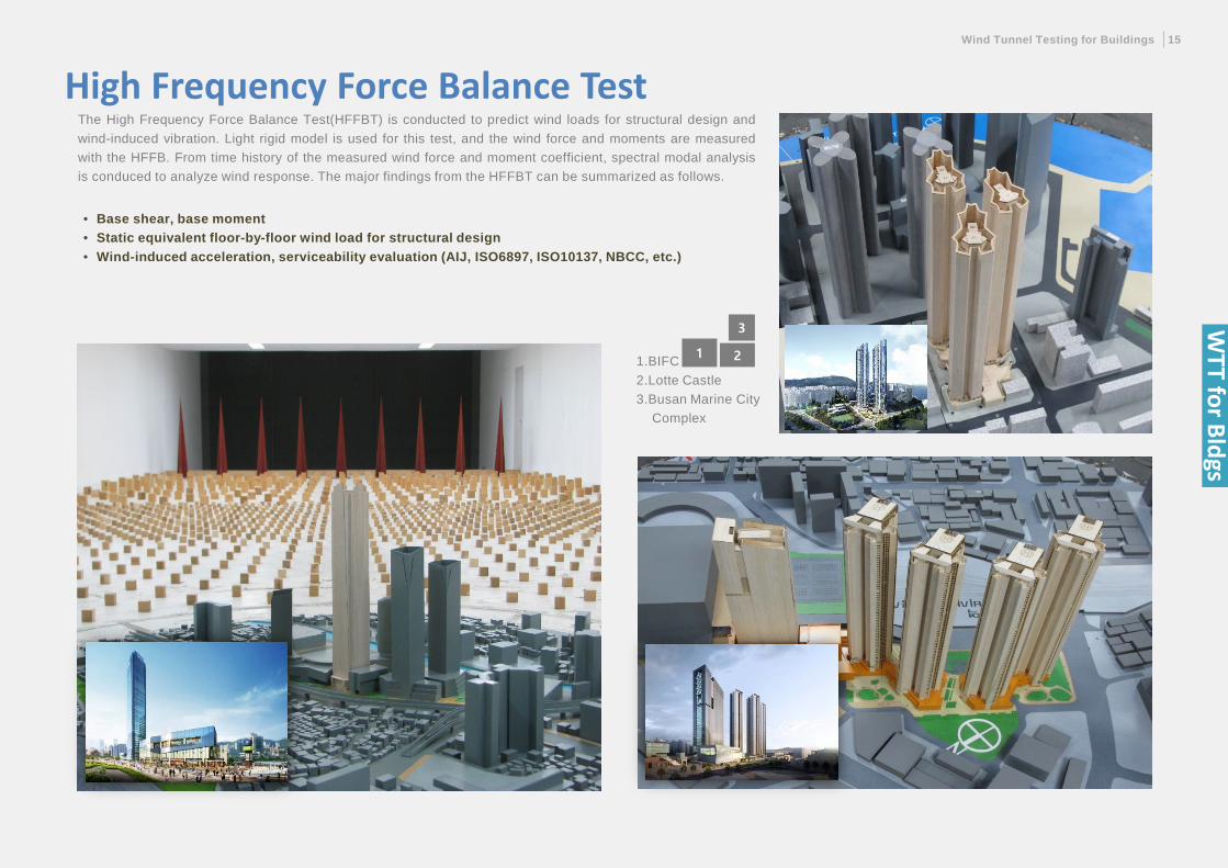
The High Frequency Force Balance Test(HFFBT) is conducted to predict wind loads for structural design andwind-induced vibration. Light rigid model is used for this test, and the wind force and moments are measuredwith the HFFB. From time history of the measured wind force and moment coefficient, spectral modal analysisis conduced to analyze wind response. The major findings from the HFFBT can be summarized as follows.
• Base shear, base moment • Static equivalent floor-by-floor wind load for structural design• Wind-induced acceleration, serviceability evaluation (AIJ, ISO6897, ISO10137, NBCC, etc.)
Wind Tunnel Testing for Buildings 15
3
211.BIFC2.Lotte Castle3.Busan Marine City
Complex
High Frequency Force Balance Test
WTT for Bldgs
3
21
1.Sarang Church, Seoul2.National Ocean Science and
Education Center3.Munhak Stadium
3
21
1.Dangjin Power Plant #9,10 Stack2.Gosung-Hi Power Plant #1,2 Stack3.Shin-Boryung Power Plant #1,2 Stack
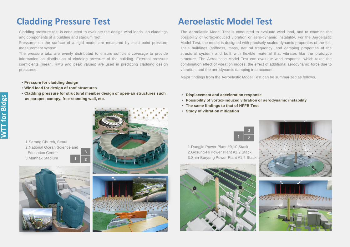
Cladding pressure test is conducted to evaluate the design wind loads on claddingsand components of a building and stadium roof.Pressures on the surface of a rigid model are measured by multi point pressuremeasurement system.The pressure tabs are evenly distributed to ensure sufficient coverage to provideinformation on distribution of cladding pressure of the building. External pressurecoefficients (mean, RMS and peak values) are used in predicting cladding designpressures.
• Pressure for cladding design• Wind load for design of roof structures• Cladding pressure for structural member design of open-air structures such
as parapet, canopy, free-standing wall, etc.
Cladding Pressure Test Aeroelastic Model TestThe Aeroelastic Model Test is conducted to evaluate wind load, and to examine thepossibility of vortex-induced vibration or aero-dynamic instability. For the AeroelasticModel Test, the model is designed with precisely scaled dynamic properties of the full-scale buildings (stiffness, mass, natural frequency, and damping properties of thestructural system) and built with flexible material that vibrates like the prototypestructure. The Aeroelastic Model Test can evaluate wind response, which takes thecombination effect of vibration modes, the effect of additional aerodynamic force due tovibration, and the aerodynamic damping into account.
Major findings from the Aeroelastic Model Test can be summarized as follows.
• Displacement and acceleration response • Possibility of vortex-induced vibration or aerodynamic instability• The same findings to that of HFFB Test• Study of vibration mitigation
WTT
for B
ldgs
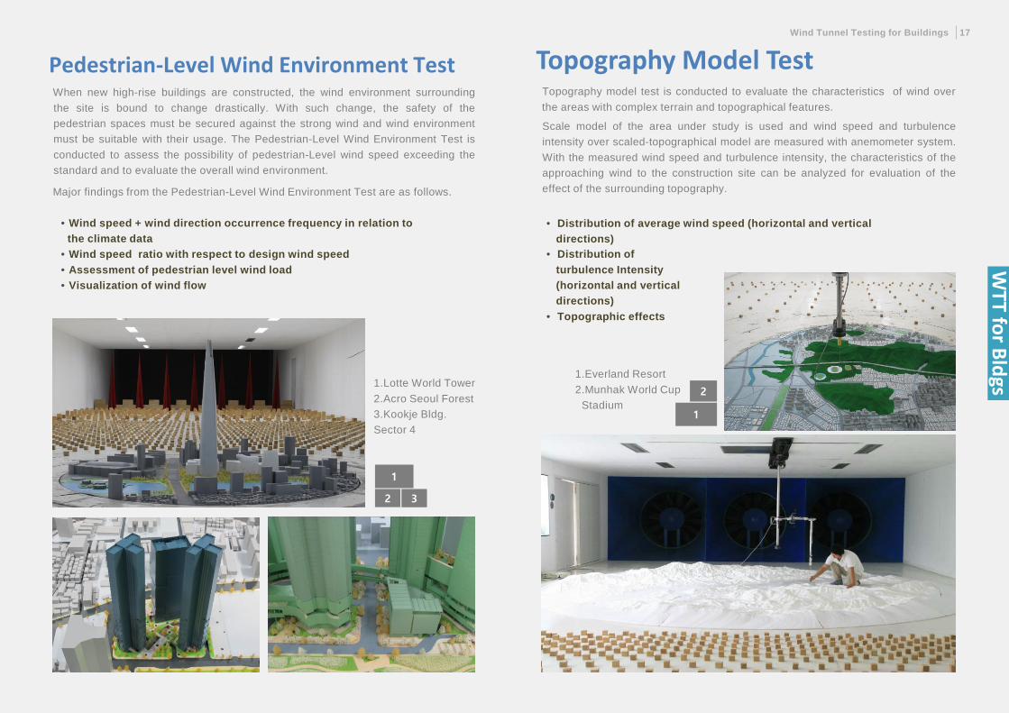
When new high-rise buildings are constructed, the wind environment surroundingthe site is bound to change drastically. With such change, the safety of thepedestrian spaces must be secured against the strong wind and wind environmentmust be suitable with their usage. The Pedestrian-Level Wind Environment Test isconducted to assess the possibility of pedestrian-Level wind speed exceeding thestandard and to evaluate the overall wind environment.
Major findings from the Pedestrian-Level Wind Environment Test are as follows.
• Wind speed + wind direction occurrence frequency in relation to the climate data
• Wind speed ratio with respect to design wind speed• Assessment of pedestrian level wind load• Visualization of wind flow
Pedestrian-Level Wind Environment TestWind Tunnel Testing for Buildings 17
2
1
1.Everland Resort2.Munhak World Cup
Stadium
2
1
3
1.Lotte World Tower2.Acro Seoul Forest 3.Kookje Bldg.Sector 4
Topography Model TestTopography model test is conducted to evaluate the characteristics of wind overthe areas with complex terrain and topographical features.
Scale model of the area under study is used and wind speed and turbulenceintensity over scaled-topographical model are measured with anemometer system.With the measured wind speed and turbulence intensity, the characteristics of theapproaching wind to the construction site can be analyzed for evaluation of theeffect of the surrounding topography.
• Distribution of average wind speed (horizontal and vertical directions)
• Distribution of turbulence Intensity (horizontal and vertical directions)
• Topographic effects
WTT for Bldgs
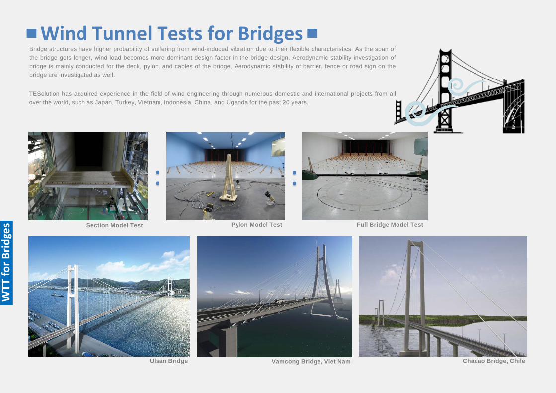
Wind Tunnel Tests for BridgesBridge structures have higher probability of suffering from wind-induced vibration due to their flexible characteristics. As the span ofthe bridge gets longer, wind load becomes more dominant design factor in the bridge design. Aerodynamic stability investigation ofbridge is mainly conducted for the deck, pylon, and cables of the bridge. Aerodynamic stability of barrier, fence or road sign on thebridge are investigated as well.
TESolution has acquired experience in the field of wind engineering through numerous domestic and international projects from allover the world, such as Japan, Turkey, Vietnam, Indonesia, China, and Uganda for the past 20 years.
Full Bridge Model TestSection Model Test
Ulsan Bridge Vamcong Bridge, Viet Nam Chacao Bridge, Chile
Pylon Model Test
: :
WTT
for B
ridge
s
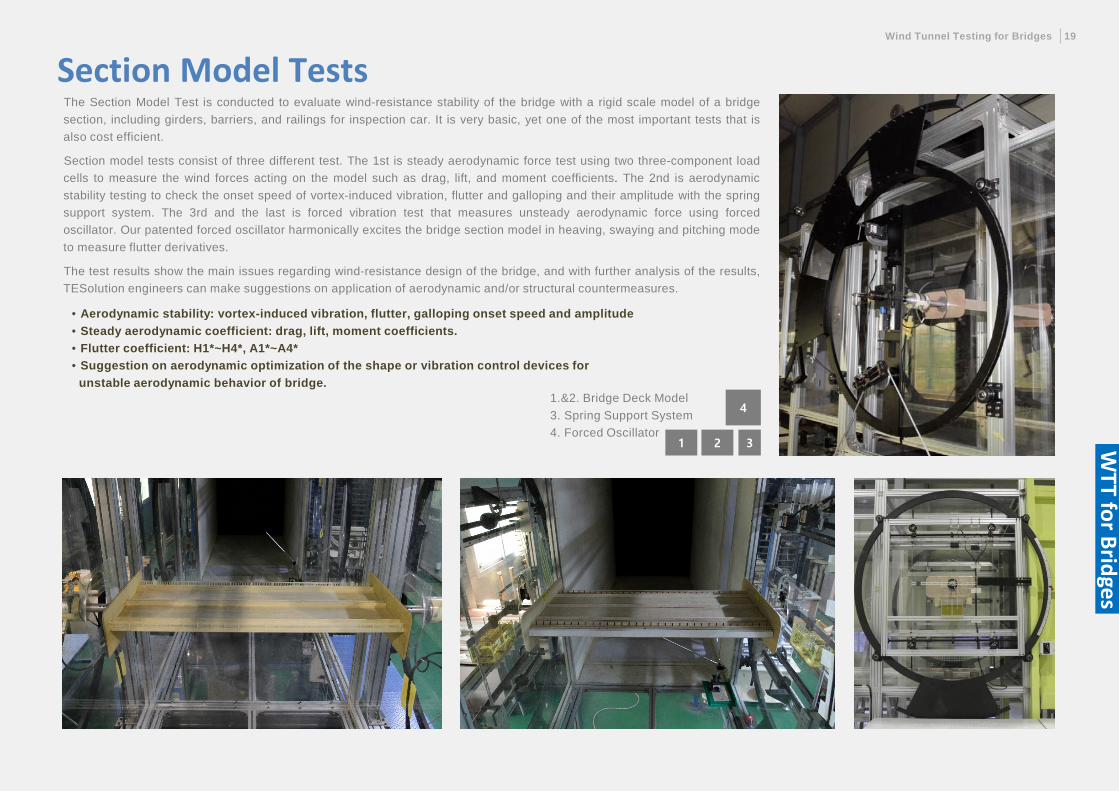
Section Model TestsThe Section Model Test is conducted to evaluate wind-resistance stability of the bridge with a rigid scale model of a bridgesection, including girders, barriers, and railings for inspection car. It is very basic, yet one of the most important tests that isalso cost efficient.
Section model tests consist of three different test. The 1st is steady aerodynamic force test using two three-component loadcells to measure the wind forces acting on the model such as drag, lift, and moment coefficients. The 2nd is aerodynamicstability testing to check the onset speed of vortex-induced vibration, flutter and galloping and their amplitude with the springsupport system. The 3rd and the last is forced vibration test that measures unsteady aerodynamic force using forcedoscillator. Our patented forced oscillator harmonically excites the bridge section model in heaving, swaying and pitching modeto measure flutter derivatives.
The test results show the main issues regarding wind-resistance design of the bridge, and with further analysis of the results,TESolution engineers can make suggestions on application of aerodynamic and/or structural countermeasures.
• Aerodynamic stability: vortex-induced vibration, flutter, galloping onset speed and amplitude• Steady aerodynamic coefficient: drag, lift, moment coefficients.• Flutter coefficient: H1*~H4*, A1*~A4*• Suggestion on aerodynamic optimization of the shape or vibration control devices for
unstable aerodynamic behavior of bridge.
Wind Tunnel Testing for Bridges 19
4
21 3
1.&2. Bridge Deck Model3. Spring Support System4. Forced Oscillator W
TT for Bridges
WTT
for B
ridge
s
3
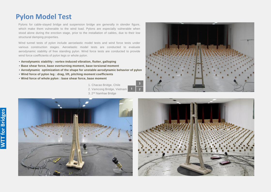
211. Chacao Bridge, Chile2. Vamcong Bridge, Vietnam3. 2nd Namhae Bridge
Pylons for cable-stayed bridge and suspension bridge are generally in slender figure,which make them vulnerable to the wind load. Pylons are especially vulnerable whenstood alone during the erection stage, prior to the installation of cables, due to their lowstructural damping properties.
Wind tunnel tests of pylon include aeroelastic model tests and wind force tests undervarious construction stages. Aeroelastic model tests are conducted to evaluateaerodynamic stability of free standing pylon. Wind force tests are conducted to providewind force coefficients of pylon legs or whole pylon.
Pylon Model Test
• Aerodynamic stability : vortex-induced vibration, flutter, galloping• Base shear force, base overturning moment, base torsional moment• Aerodynamic optimization of the shape for unstable aerodynamic behavior of pylon• Wind force of pylon leg : drag, lift, pitching moment coefficients• Wind force of whole pylon : base shear force, base moment
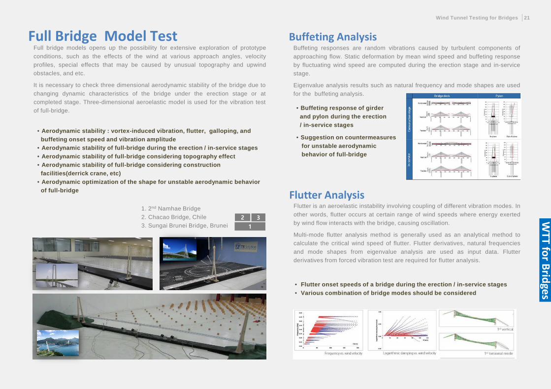
Buffeting responses are random vibrations caused by turbulent components ofapproaching flow. Static deformation by mean wind speed and buffeting responseby fluctuating wind speed are computed during the erection stage and in-servicestage.
Eigenvalue analysis results such as natural frequency and mode shapes are usedfor the buffeting analysis.
Buffeting Analysis
Flutter is an aeroelastic instability involving coupling of different vibration modes. Inother words, flutter occurs at certain range of wind speeds where energy exertedby wind flow interacts with the bridge, causing oscillation.
Multi-mode flutter analysis method is generally used as an analytical method tocalculate the critical wind speed of flutter. Flutter derivatives, natural frequenciesand mode shapes from eigenvalue analysis are used as input data. Flutterderivatives from forced vibration test are required for flutter analysis.
• Flutter onset speeds of a bridge during the erection / in-service stages• Various combination of bridge modes should be considered
Flutter Analysis
Wind Tunnel Testing for Bridges 21
WTT for Bridges
2
1
3
1. 2nd Namhae Bridge2. Chacao Bridge, Chile3. Sungai Brunei Bridge, Brunei
Full Bridge Model TestFull bridge models opens up the possibility for extensive exploration of prototypeconditions, such as the effects of the wind at various approach angles, velocityprofiles, special effects that may be caused by unusual topography and upwindobstacles, and etc.
It is necessary to check three dimensional aerodynamic stability of the bridge due tochanging dynamic characteristics of the bridge under the erection stage or atcompleted stage. Three-dimensional aeroelastic model is used for the vibration testof full-bridge.
• Aerodynamic stability : vortex-induced vibration, flutter, galloping, and buffeting onset speed and vibration amplitude
• Aerodynamic stability of full-bridge during the erection / in-service stages• Aerodynamic stability of full-bridge considering topography effect• Aerodynamic stability of full-bridge considering construction
facilities(derrick crane, etc)• Aerodynamic optimization of the shape for unstable aerodynamic behavior
of full-bridge
• Buffeting response of girder and pylon during the erection / in-service stages
• Suggestion on countermeasures for unstable aerodynamic behavior of full-bridge
Computational Wind Engineering (CWE) uses Computational Fluid Dynamics(CFD) method to solve problems encountered in wind engineering. Numericalmodeling with CFD can be a powerful alternative as it can avoid limitations ofon-site measurements and wind tunnel tests. CFD can provide detailedinformation on the relevant flow variables in the whole calculation domain underwell-controlled conditions.
Computational Wind Engineering
CFD is used to investigate static aerodynamic forces, wind velocity, vortex, andpressure distributions near the bridge. Also, the occurrence of flutter and vortexinduced vibration are estimated with FSI(Fluid Structure Interaction) analysis.
CFD/FSI Analysis
CFD is typically used for predictionof wind comfort, pollution dispersion,natural ventilation of building, windload on buildings, static aero-dynamic force and flutter analysis ofa bridge.
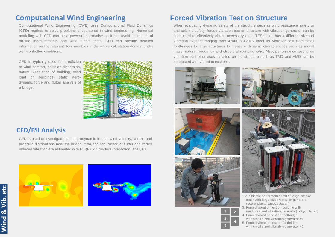
Forced Vibration Test on Structure
1 2
34
5
Win
d &
Vib
. etc
1.2. Seismic performance test of large smokestack with large sized vibration generator(power plant, Nagoya Japan)
3. Forced vibration test on building with medium sized vibration generator(Tokyo, Japan)
4. Forced vibration test on footbridge with small sized vibration generator #1
5. Forced vibration test on footbridge with small sized vibration generator #2
When evaluating dynamic safety of the structure such as wind resistance safety oranti-seismic safety, forced vibration test on structure with vibration generator can beconducted to effectively obtain necessary data. TESolution has 4 different sizes ofvibration exciters ranging from 42kN to 420kN ideal for vibration test from smallfootbridges to large structures to measure dynamic characteristics such as modalmass, natural frequency and structural damping ratio. Also, performance testing onvibration control devices installed on the structure such as TMD and AMD can beconducted with vibration exciters .
Analytics of Wind & Vibration 23
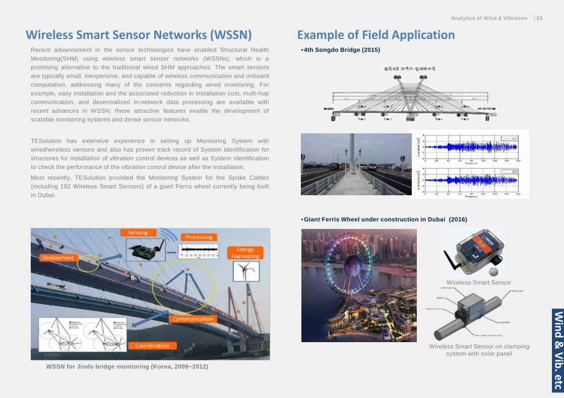
•4th Songdo Bridge (2015)
Example of Field ApplicationRecent advancement in the sensor technologies have enabled Structural HealthMonitoring(SHM) using wireless smart sensor networks (WSSNs), which is apromising alternative to the traditional wired SHM approaches. The smart sensorsare typically small, inexpensive, and capable of wireless communication and onboardcomputation, addressing many of the concerns regarding wired monitoring. Forexample, easy installation and the associated reduction in installation cost, multi-hopcommunication, and decentralized in-network data processing are available withrecent advances in WSSN; these attractive features enable the development ofscalable monitoring systems and dense sensor networks.
TESolution has extensive experience in setting up Monitoring System withwired/wireless sensors and also has proven track record of System Identification forstructures for installation of vibration control devices as well as System Identificationto check the performance of the vibration control device after the installation.
Most recently, TESolution provided the Monitoring System for the Spoke Cables(including 192 Wireless Smart Sensors) of a giant Ferris wheel currently being builtin Dubai.
Wireless Smart Sensor Networks (WSSN)
WSSN for Jindo bridge monitoring (Korea, 2009~2012)
•Giant Ferris Wheel under construction in Dubai (2016)
Wireless Smart Sensor
Wireless Smart Sensor on clamping system with solar panel
Wind &
Vib. etc
Track Record of TESolution
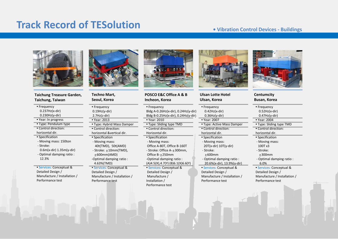
Taichung Treasure Garden, Taichung, Taiwan
Techno Mart, Seoul, Korea
POSCO E&C Office A & BIncheon, Korea
Ulsan Lotte HotelUlsan, Korea
▪ Frequency 0.237Hz(x-dir)0.230Hz(y-dir)▪ Year: In progress▪ Type: Pendulum type▪ Control direction: horizontal dir.▪ Specification- Moving mass: 150ton- Stroke:
0.6m(x-dir) 1.35m(y-dir)- Optimal damping ratio :
12.3%
▪ Services: Conceptual & Detailed Design / Manufacture / Installation /Performance test
▪ Frequency 0.19Hz(y-dir)2.7Hz(z-dir) ▪ Year: 2013▪ Type: Hybrid Mass Damper▪ Control direction: horizontal &vertical dir.▪ Specification- Moving mass:
40t(TMD), 50t(AMD)- Stroke: ±10mm(TMD), ±600mm(AMD)
-Optimal damping ratio : 4.63%(TMD) ▪ Services: Conceptual & Detailed Design / Manufacture / Installation /Performance test
▪ Frequency Bldg A-0.26Hz(x-dir), 0.24Hz(y-dir)Bldg B-0.25Hz(x-dir), 0.24Hz(y-dir)▪ Year: 2010▪ Type: Sliding type TMD▪ Control direction: Horizontal dir.▪ Specification- Moving mass: Office A-80T, Office B-160T- Stroke: Office A-±300mm, Office B-±250mm -Optimal damping ratio : (A)4.5(X),4.7(Y) (B)6.1(X)6.6(Y)▪ Services: Conceptual &Detailed Design /Manufacture /
Installation /Performance test
▪ Frequency 0.42Hz(x-dir)0.36Hz(y-dir)▪ Year: 2007▪ Type: Active Mass Damper▪ Control direction: horizontal dir.▪ Specification- Moving mass:20T(x-dir) 10T(y-dir)
- Stroke: ±600mm
- Optimal damping ratio : 20.6%(x-dir), 13.9%(y-dir) ▪ Services: Conceptual & Detailed Design / Manufacture / Installation /Performance test
CentumcityBusan, Korea
▪ Frequency 0.52Hz(x-dir)0.47Hz(y-dir)▪ Year: 2004▪ Type: Sliding type TMD▪ Control direction: horizontal dir.▪ Specification- Moving mass:100T x3
- Stroke: ±300mm
- Optimal damping ratio : 6.0%
▪ Services: Conceptual & Detailed Design / Manufacture / Installation /Performance test
• Vibration Control Devices - Buildings
Track Record of TESolution
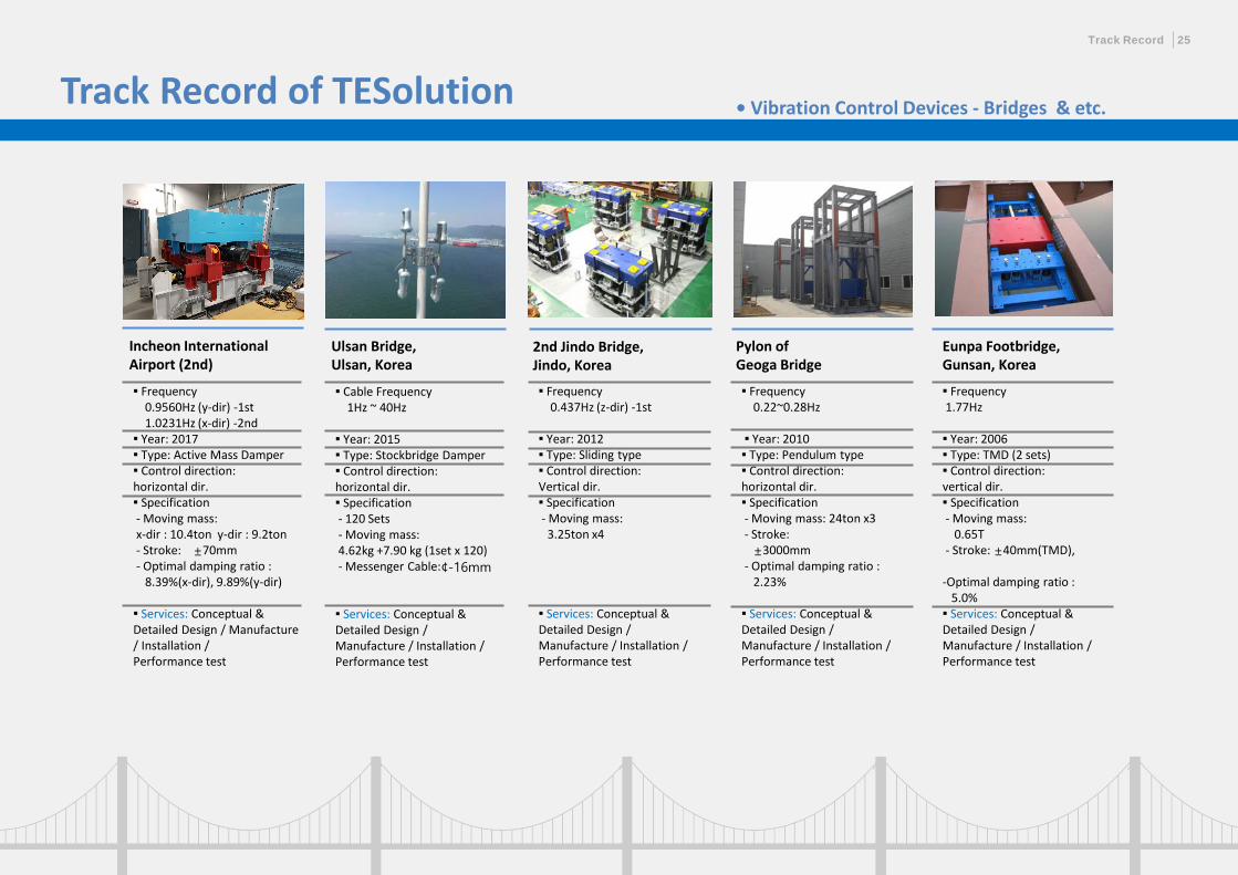
Ulsan Bridge,Ulsan, Korea
2nd Jindo Bridge,Jindo, Korea
Pylon ofGeoga Bridge
▪ Cable Frequency 1Hz ~ 40Hz
▪ Year: 2015▪ Type: Stockbridge Damper▪ Control direction: horizontal dir.▪ Specification- 120 Sets- Moving mass:4.62kg +7.90 kg (1set x 120)- Messenger Cable:¢-16mm
▪ Services: Conceptual & Detailed Design / Manufacture / Installation /Performance test
▪ Frequency 0.437Hz (z-dir) -1st
▪ Year: 2012▪ Type: Sliding type▪ Control direction: Vertical dir.▪ Specification- Moving mass: 3.25ton x4
▪ Services: Conceptual & Detailed Design / Manufacture / Installation /Performance test
▪ Frequency 0.22~0.28Hz
▪ Year: 2010▪ Type: Pendulum type▪ Control direction: horizontal dir.▪ Specification- Moving mass: 24ton x3- Stroke: ±3000mm
- Optimal damping ratio : 2.23%
▪ Services: Conceptual & Detailed Design / Manufacture / Installation /Performance test
Incheon International Airport (2nd)
▪ Frequency 0.9560Hz (y-dir) -1st1.0231Hz (x-dir) -2nd ▪ Year: 2017▪ Type: Active Mass Damper▪ Control direction: horizontal dir.▪ Specification- Moving mass:x-dir : 10.4ton y-dir : 9.2ton - Stroke: ±70mm- Optimal damping ratio :
8.39%(x-dir), 9.89%(y-dir)
▪ Services: Conceptual & Detailed Design / Manufacture / Installation /Performance test
• Vibration Control Devices - Bridges & etc.
Eunpa Footbridge, Gunsan, Korea
▪ Frequency 1.77Hz
▪ Year: 2006▪ Type: TMD (2 sets)▪ Control direction: vertical dir.▪ Specification- Moving mass:
0.65T- Stroke: ±40mm(TMD),
-Optimal damping ratio : 5.0%▪ Services: Conceptual & Detailed Design / Manufacture / Installation /Performance test
Track Record 25
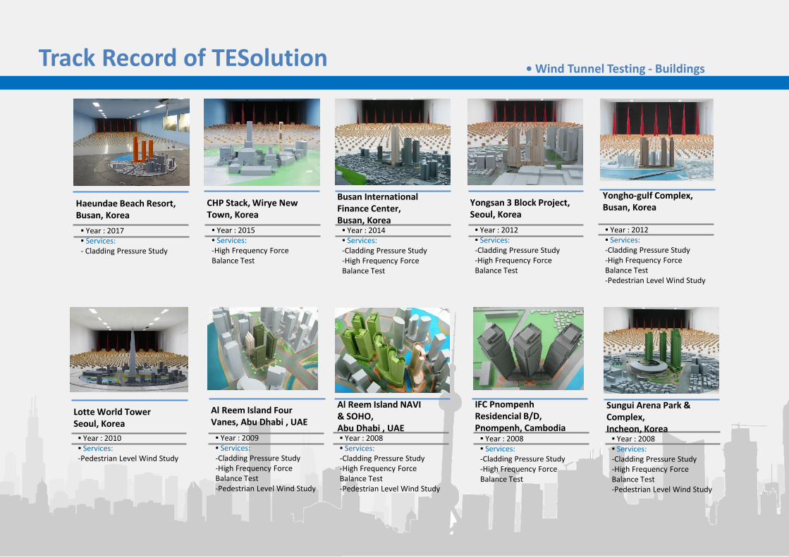
Track Record of TESolution • Wind Tunnel Testing - Buildings
▪ Year : 2008▪ Services:-Cladding Pressure Study-High Frequency Force Balance Test-Pedestrian Level Wind Study
▪ Year : 2008▪ Services:-Cladding Pressure Study-High Frequency Force Balance Test-Pedestrian Level Wind Study
▪ Year : 2017▪ Services:- Cladding Pressure Study
▪ Year : 2012▪ Services:-Cladding Pressure Study-High Frequency Force Balance Test
▪ Year : 2009▪ Services:-Cladding Pressure Study-High Frequency Force Balance Test-Pedestrian Level Wind Study
▪ Year : 2008▪ Services:-Cladding Pressure Study-High Frequency Force Balance Test
▪ Year : 2012▪ Services:-Cladding Pressure Study-High Frequency Force Balance Test-Pedestrian Level Wind Study
▪ Year : 2015▪ Services:-High Frequency Force Balance Test
▪ Year : 2014▪ Services:-Cladding Pressure Study-High Frequency Force Balance Test
▪ Year : 2010▪ Services:-Pedestrian Level Wind Study
Sungui Arena Park & Complex,Incheon, Korea
Al Reem Island NAVI & SOHO, Abu Dhabi , UAE
Haeundae Beach Resort, Busan, Korea
Al Reem Island Four Vanes, Abu Dhabi , UAE
IFC Pnompenh Residencial B/D, Pnompenh, Cambodia
Yongho-gulf Complex, Busan, KoreaCHP Stack, Wirye New
Town, KoreaYongsan 3 Block Project, Seoul, Korea
Busan International Finance Center, Busan, Korea
Lotte World TowerSeoul, Korea
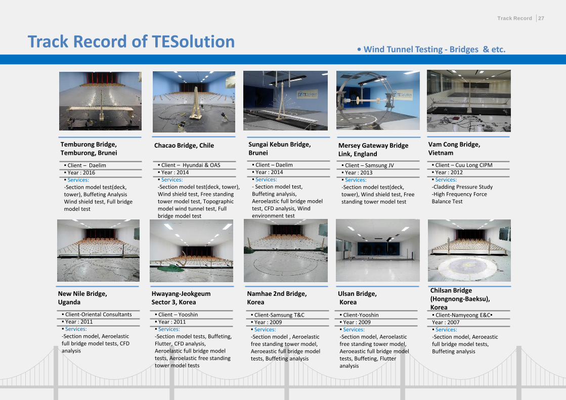
Track Record of TESolution • Wind Tunnel Testing - Bridges & etc.
Chacao Bridge, Chile Sungai Kebun Bridge, Brunei
Mersey Gateway Bridge Link, England
▪ Client – Daelim▪ Year : 2014▪ Services:- Section model test, Buffeting analysis, Aeroelastic full bridge model test, CFD analysis, Wind environment test
Chilsan Bridge (Hongnong-Baeksu),Korea
▪ Client – Samsung JV▪ Year : 2013▪ Services:-Section model test(deck, tower), Wind shield test, Free standing tower model test
▪ Client-Namyeong E&C▪Year : 2007▪ Services:-Section model, Aeroeasticfull bridge model tests, Buffeting analysis
Temburong Bridge, Temburong, Brunei
Hwayang-Jeokgeum Sector 3, Korea
Namhae 2nd Bridge, Korea
Ulsan Bridge,Korea
▪ Client – Yooshin▪ Year : 2011▪ Services:-Section model tests, Buffeting, Flutter, CFD analysis, Aeroelastic full bridge model tests, Aeroelastic free standing tower model tests
▪ Client-Samsung T&C▪ Year : 2009▪ Services:-Section model , Aeroelasticfree standing tower model, Aeroeastic full bridge model tests, Buffeting analysis
▪ Client-Yooshin▪ Year : 2009▪ Services:-Section model, Aeroelasticfree standing tower model, Aeroeastic full bridge model tests, Buffeting, Flutter analysis
New Nile Bridge, Uganda
▪ Client-Oriental Consultants▪ Year : 2011▪ Services:-Section model, Aeroelastic full bridge model tests, CFD analysis
Vam Cong Bridge, Vietnam
▪ Client – Cuu Long CIPM▪ Year : 2012▪ Services:-Cladding Pressure Study-High Frequency Force Balance Test
▪ Client – Daelim▪ Year : 2016▪ Services:-Section model test(deck, tower), Buffeting Analysis Wind shield test, Full bridge model test
▪ Client – Hyundai & OAS▪ Year : 2014▪ Services:-Section model test(deck, tower), Wind shield test, Free standing tower model test, Topographic model wind tunnel test, Full bridge model test
Track Record 27
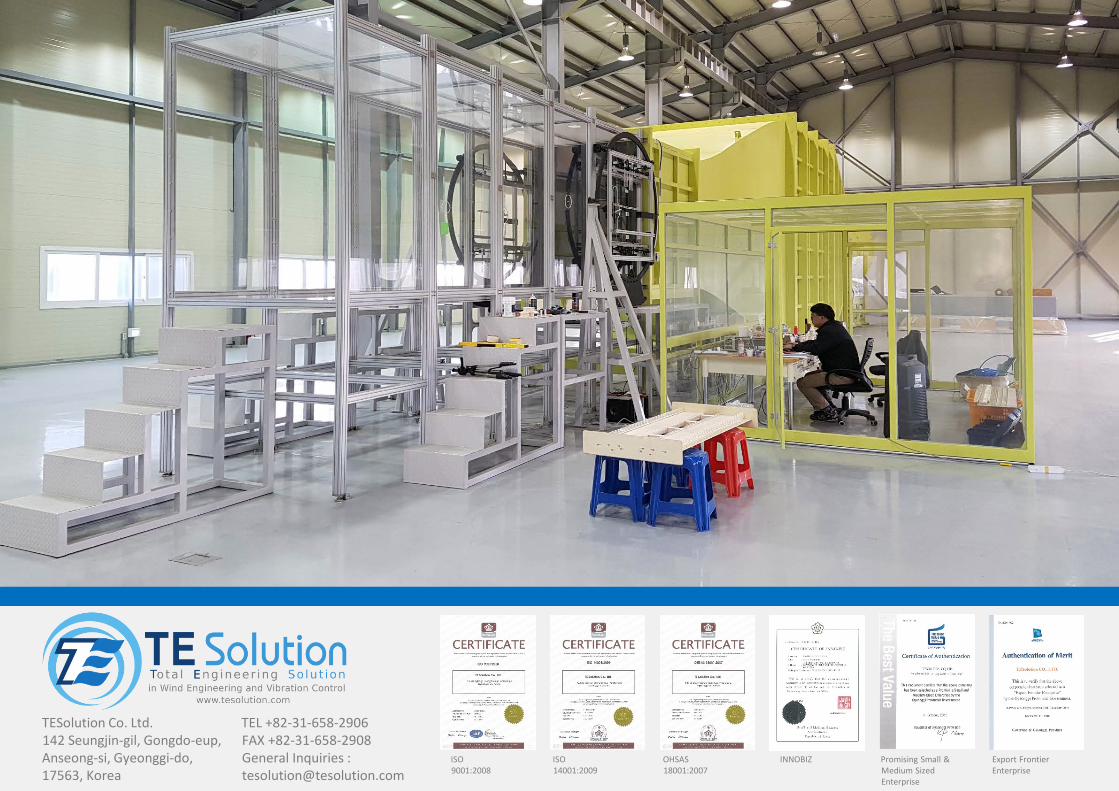
ISO 9001:2008
ISO 14001:2009
OHSAS 18001:2007
INNOBIZ Promising Small & Medium Sized Enterprise
Export FrontierEnterprise
TESolution Co. Ltd.142 Seungjin-gil, Gongdo-eup, Anseong-si, Gyeonggi-do, 17563, Korea
TEL +82-31-658-2906FAX +82-31-658-2908General Inquiries : [email protected]