Embed Size (px)
Citation preview
file://NoURLProvided[1/23/2021 1:16:02 PM]
Styling andAnnotations
0 Styling
0 Annotations
1/23/2021 1:16:02 PM
Compare Results
Total Changes
174Text only comparison
Content
79 Replacements
83 Insertions
12 Deletions
Go to First Change (page 1)
Old File:
ust_si-process_technical-chapter-3-2_automatic-tank-gauging.pdf
35 pages (1.92 MB)10/26/2015 11:13:30 AM
versus
New File:
Technical Chapter 3.2 Automatic TankGauging draft 20210123_b_noblueline.pdf
41 pages (4.78 MB)1/23/2021 1:10:49 PM
DRAFT
Automatic Tank Gauging Standardized Inspection Manual
Technical Chapter 3.2
Tennessee Department of Environment & Conservation
Division of Underground Storage Tanks
Rules Effective October 13, 2018
Document Last Edited: 1/23/2021

DRAFT
This page left intentionally blank
DRAFT
i
Table of Contents
1. PURPOSE ............................................................................................................................ 1
2. AUTHORITY ........................................................................................................................ 1
3. APPLICABILITY ................................................................................................................... 1
4. INTRODUCTION ................................................................................................................ 2
5. DEFINITIONS: ..................................................................................................................... 4
6. COMPONENTS OF AUTOMATIC TANK GAUGING SYSTEMS ......................................... 5
a. Magnetostrictive ............................................................................................................ 5
b. Capacitance .................................................................................................................... 5
c. Ultrasonic ....................................................................................................................... 5
d. Mass measurement....................................................................................................... 6
7. TYPES OF MONITORING METHODS FOR AUTOMATIC TANK GAUGING SYSTEMS .... 6
a. Static ................................................................................................................................ 6
b. Continuous ..................................................................................................................... 6
1. Continuous Automatic Tank Gauging .................................................................... 7
2. Continuous In-Tank Leak Detection Systems (Continual Reconciliation) .......... 7
8. REQUIREMENTS ................................................................................................................ 8
a. 2018 RULE CHANGE REQUIREMENTS .......................................................................... 8
9. EXAMPLES OF AUTOMATIC TANK GAUGING CONSOLES ............................................. 9
10. COMMON PROBLEMS ASSOCIATED WITH ATG SYSTEMS .......................................... 11
a. 24-Hour UST Systems .................................................................................................. 11
b. Alarms Not Properly Investigated .............................................................................. 11
c. Monthly Leak Test Reports Not Maintained ............................................................. 12
d. Tank Owner/ Operator Unfamiliar with ATG Operation ......................................... 12
e. Tank Fuel Volume Too Low for Valid Leak Test ........................................................ 12
f. ATG Not Programmed Properly ................................................................................. 12
g. Third Party Evaluation for Large Capacity or Manifolded Tank Systems .............. 13
h. ATG System Not Routinely Inspected ........................................................................ 13
i. ATG Static Leak Threshold Set Incorrectly ................................................................ 13
j. ATG used for Tank Tightness Testing ........................................................................ 13
k. Probes with Ethanol-blended Fuels ........................................................................... 13
DRAFT
ii
l. Submittal of Inaccurate Records ................................................................................ 13
11. REASONS WHY TANK LEAK TESTS FAIL......................................................................... 14
a. An actual leak has occurred. ...................................................................................... 14
b. Temperature instability after product delivery ........................................................ 14
c. ATG Tank Chart Accuracy- accuracy of 1-point profile for FRP tanks (minimum 4 point required by Veeder-Root). ..................................................................................... 14
d. Large changes in product temp. from the beginning to the end of the test. ....... 14
e. Water level changes from the beginning to the end of the test. ........................... 14
f. Tank Deformation/Deflection .................................................................................... 14
g. Tank Crosstalk .............................................................................................................. 14
h. Product is being dispensed during a leak test. ........................................................ 14
i. Equipment malfunction .............................................................................................. 14
12. RECORDKEEPING ............................................................................................................ 14
13. TYPES OF REPORTS ......................................................................................................... 16
a. In-Tank Inventory ......................................................................................................... 16
b. Static Leak Test (0.2 or 0.1 gph) ................................................................................. 17
c. Continuous (CSLD or SCALD) Leak Test .................................................................... 18
d. Tank Leak Test History ................................................................................................ 19
e. In-Tank Setup ............................................................................................................... 20
f. In-Tank Alarm History ................................................................................................. 21
g. Sensor Alarm History .................................................................................................. 22
14. INTERPRETATION OF SETUP INFORMATION TO BE REVIEWED ONSITE ................... 22
15. VEEDER-ROOT TLS-3XX SETUP: ..................................................................................... 23
16. INCON TANK SENTINEL SETUP: ..................................................................................... 25
17. REPORTING ...................................................................................................................... 29
REFERENCES .......................................................................................................................... 30
APPENDICES .......................................................................................................................... 31
APPENDIX 1: ATG Leak Detection Quick Reference Table ............................................... 32
APPENDIX 2: Automatic Tank Gauge Operability Test Procedure .................................. 33
DRAFT
1
STATE OF TENNESSEE
DEPARTMENT OF ENVIRONMENT AND CONSERVATION DIVISION OF UNDERGROUND STORAGE TANKS
TECHNICAL CHAPTER 3.2 AUTOMATIC TANK GAUGING
1. PURPOSE The purpose of this technical chapter is to assist Division of Underground Storage Tanks (Division) staff in understanding the regulatory requirements for the operation, features, release detection, and record keeping requirements for underground storage tank (UST) systems which utilize Automatic Tank Gauging (ATG) for leak detection. This technical chapter contains the current policy of the Division based on the statute and regulations governing the Tennessee Petroleum Underground Storage Tank program.
2. AUTHORITY All rules referred to in this technical chapter are contained in Chapter 0400-18-01 and are available on the Division of Underground Storage Tanks website at https://publications.tnsosfiles.com/rules/0400/0400-18/0400-18-01.20181013.pdf
3. APPLICABILITY This document provides technical and specific industry knowledge regarding the operation, maintenance, and release detection requirements for UST systems equipped with ATG systems. The document also provides recommended practices for inspection, discussion of common problems associated with ATG systems, and a discussion of the most common types of ATG systems utilized at UST facilities. Each ATG system must be evaluated by a third party and subsequently listed by the National Work Group on Leak Detection Evaluations (NWGLDE).1 All ATG systems must be third party certified to test for leaks at 0.2 gph on a monthly basis2, with a 95% probability of detection, with no more than a 5% probability of false alarm as required by rule .04(1)(a)4. The NWGLDE evaluations list may be accessed at www.nwglde.org.
1Required by Rule 0400-18-01.04(1)(a)5 2 Required by Rule0400-18-01.04(3)(c)1
DRAFT
2
4. INTRODUCTION ATG systems were originally developed by petroleum tank system manufacturers as a method of determining the amount of fuel in a tank without the use of a tank gauging stick. The earliest versions of ATGs were essentially gauging sticks which a facility operator could use to determine how much fuel was present in a UST system. These readings were used to conduct monthly inventory control and no additional leak testing was conducted. As technology advanced, additional features were incorporated into the device. Water level measurements, product temperature, leak alarms, and eventually in-tank leak detection was developed and included by the Environmental Protection Agency (EPA) for use as a leak detection method. Today there are numerous manufacturers which produce ATG systems, each with its own features and benefits. As technology in the petroleum industry has advanced, most modern UST facilities are now equipped with an ATG which can measure liquid levels within an accuracy of 1/1000th of an inch.
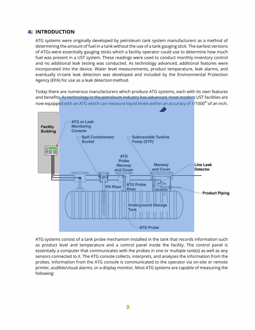
ATG systems consist of a tank probe mechanism installed in the tank that records information such as product level and temperature and a control panel inside the facility. The control panel is essentially a computer that communicates with the probes in one or multiple tank(s) as well as any sensors connected to it. The ATG console collects, interprets, and analyzes the information from the probes. Information from the ATG console is communicated to the operator via on-site or remote printer, audible/visual alarms, or a display monitor. Most ATG systems are capable of measuring the following:
DRAFT
3
Gross volume- the volume of product in the tank based on the product depth and the tank’s depth to volume conversion factor.
Product temperature- the average temperature of product in the tank.
Net volume- temperature-compensated volume of product (calculated at 60 degrees Fahrenheit).
Water level- the amount of water in the tank in inches/gallons.
Product level- amount of the product in the tank in inches/gallons.
Ullage- the capacity of the tank minus the gross volume of product, or empty space above the product level (usually expressed in gallons).
Net delivered product volume- an automatic calculation of delivery volume based on before and after product level and temperature measurements. This volume is temperature compensated to 60 degrees F of product delivered.
Leak test result- the results of the most recent as well as past leak tests. The result of a leak test may be PASS, FAIL, INVALID, INCREASE, or TEST ABORTED, etc. Some ATG systems may include the term SLOPE which is equivalent to the calculated leak rate.
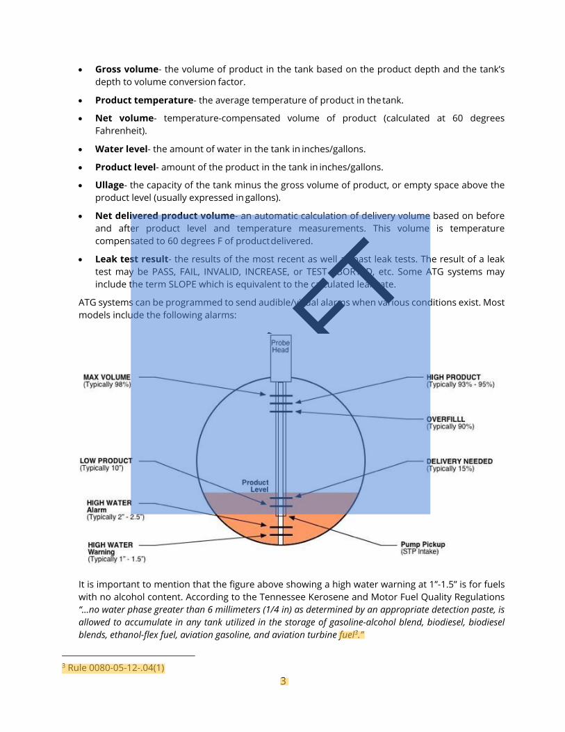
ATG systems can be programmed to send audible/visual alarms when various conditions exist. Most models include the following alarms:
It is important to mention that the figure above showing a high water warning at 1”-1.5” is for fuels with no alcohol content. According to the Tennessee Kerosene and Motor Fuel Quality Regulations “...no water phase greater than 6 millimeters (1/4 in) as determined by an appropriate detection paste, is allowed to accumulate in any tank utilized in the storage of gasoline-alcohol blend, biodiesel, biodiesel blends, ethanol-flex fuel, aviation gasoline, and aviation turbine fuel3.”
3 Rule 0080-05-12-.04(1)
DRAFT
4
In 2015 EPA amended the federal underground storage tank regulations to require routine service and maintenance for ATG components. Tennessee’s implementation of these rules for new tank systems began on October 13, 2018. However, since interstitial monitoring is required as the primary method of release detection for all UST systems installed after July 2, 2007 4, in-tank monitoring for releases using devices described in this chapter are no longer allowed for those systems.
5. DEFINITIONS: Continuous In-Tank Leak Detection System (CITLDS): acronym used by Warren Rogers Associates for CITLDS, which is a third party approved leak detection method utilizing an ATG to collect multiple points of data for in-tank leak detection at high throughput facilities. The advantage of using CITLDS is that tank systems do not have to be taken out of service each month to conduct a static test.
Please see Technical Chapter 3.3 Statistical Inventory Reconciliation for more detailed information on this method.
Continuous Statistical Leak Detection (CSLD): another term also used to refer to continuous ATG systems.
Leak Rate: a positive number expressed in gallons per hour (gph), measured by the test device that indicates the amount of product that may be leaking out of the tank system. A negative number may indicate that something was being added to the tank (delivery) or may be caused by a thermal effect due to product expansion.
Leak Threshold: the measured leak rate at which an ATG system determines the tank to be leaking. The leak threshold will always be less than or equal to the leak rate requirement for the ATG system. For typical ATG systems, the leak rate is set at 0.2 gph and the leak threshold is set at the leak threshold value determined in the third party evaluation.
Quiet Time: amount of time between dispensing when continuous leak test data is collected.
Statistical Continuous Automatic Leak Detection (SCALD): another term used for continuous ATG systems used by Franklin Fueling (INCON).
Tank Capacity: the volume of product a tank will hold in gallons. Tank capacities are reported as “nominal” capacities which means the true capacity may be smaller or larger due to allowable tolerances in manufacturers’ processes.
Test Period: the length of the leak test as determined by the third party evaluation. This is only applicable to static testing.
Ullage: the portion of unfilled space above the liquid level in an underground storage tank, usually expressed in gallons.
Waiting Time: minimum amount of time after fuel deliveries before a leak test can begin.
90% Ullage: tank specific fuel level that the ATG system uses as a target threshold to ensure that tank overfills do not occur. This level is set at 90% of the entire tank capacity.
4 Required by Rule 0400-18-01-.01(1)(c)
DRAFT
5
6. COMPONENTS OF AUTOMATIC TANK GAUGING SYSTEMS Console- see photos on page 9. Probe Types For these types of ATG systems to operate properly, all leak tests must be performed during a period when no fuel is added to or removed from the tank.
a. Magnetostrictive
A magnetostrictive probe works on the principle that sound maintains a constant velocity despite temperature differences that may occur along its route of travel. When this principle is employed in an ATG system, a vertical pipe is installed in the tank. A wire runs down the center of the full length of the pipe. Around the outside of the pipe is a doughnut-shaped float that contains a strong magnet. Magnetic flux from this floating magnet impinges on the wire at the liquid level in the tank. For measurement of this level, a sound wave is injected into the top end of the wire and when the sound wave reaches the level of the magnetic float, the vibration of the wire causes electricity to be generated in the wire. With repeated calculation of the time between the start of the sound pulse and the start of the subsequent electrical pulse, the precise level of the float can be determined.
b. Capacitance
Certain ATG systems utilize capacitance type liquid measurement as a means of detecting changes in the depth of liquid in a storage tank. A hollow metal tube, with a smaller electronic tube running down its center, is installed vertically in an underground storage tank. The outside surface of the inside tube and the inside surface of the outside tube form the two plates of a capacitor. The space between them is then converted to a measurement of the liquid level in the tank which is translated on a gauging instrument.
Capacitance probes do not work with ethanol blended fuels.5
c. Ultrasonic
A sensor detects sound wave echoes reflected from an interface of water/fuel or fuel/air to calculate the liquid level based on the speed of sound in the media.
5 Required by Rule 0400-18-01-.04(1)(a)5
DRAFT
6
d. Mass measurement Mass buoyancy probes operate on the Archimedes Principle, and measure the weight of a probe or load cell suspended in the fuel during the test period. Any changes in the weight of the suspended object can be converted to a volume change and the amount of fuel (in gallons/inches) in the tank can be determined. Mass buoyancy ATG measurements are not affected by changes in product temperature. However, they require a test period when nothing is added to or removed from the tank.
7. TYPES OF MONITORING METHODS FOR AUTOMATIC TANK GAUGING SYSTEMS
a. Static This method is typically done by taking the tank out of service and putting the ATG into test mode on a monthly basis at a minimum.6 ATGs can be programmed to run static tests at any time. If a static test is being conducted and a consumer attempts to purchase fuel, it will invalidate the test result. The ATG might interpret this as a sudden loss. If a test has not been conducted at the end of the month, a tank owner has no monthly record for their release detection. 7 (See Appendix 1 for ATG reference guide)
b. Continuous These systems may use different techniques; however, they share the characteristic of monitoring tank data continuously for days, weeks, or months, and then providing leak detection capabilities on demand once the initial data requirements are met. They may use many data items, including product height, product temperature, presence or depth of water, the tank chart or geometry, meter readings, delivery records, etc., collected continually. The advantage of using continuous systems is that tank systems using this method do not have to be taken out of service each month to conduct a static test. 6Continuous systems use an ATG to collect product level measurements and employ three different techniques to generate results.
6 Required by Rule 0400-18-01-.04(3)(c)1(i) 7 Required by Rule 0400-18-01-.04(3)(c)(2.
DRAFT
7
Three techniques are described in the Evaluation Protocol for Continuous In-Tank Leak Detection Systems Revision 1 dated January 7, 2000.
1. Continuous Automatic Tank Gauging
These systems use an ATG probe to collect data continually and combine this with software to identify time intervals when there is no activity in the tank and the data are stable enough for analysis. An algorithm then combines data from a number of such periods until there is enough evidence to make a determination about the leak status of the tank. This type of system functions like an ATG except that it does not require that the tank be taken out of service for a set period of several hours whenever a test is to be done. Instead, it uses data from shorter stable time periods and combines the results to estimate a leak rate and perform a test. The system may default to a standard or shut down ATG test (requiring the tank to be out of service for a few hours) at the end of the month if sufficient good quality data have not been obtained over the month. Continuous ATG systems may use the same probe in a tank as a similar ATG to collect temperature and level measurements and report them to a console. However, whereas an ATG requires a specified waiting time after a delivery and a further period of no dispensing or delivery operations while it conducts a leak test (a shutdown period), the Continuous ATG system is designed to avoid such specified shut downs of normal tank operation. It does this by collecting data continuously. The software identifies segments of stable data, stores these data, and combines numerous such segments to produce a leak rate estimate that is used to determine whether the tank is tight or not. For high throughput tanks, a period of several days or weeks may be needed for the system to acquire sufficient data to make its determination. Once an adequate data base is obtained, a test can be conducted at any time by operator request. The test is based on the most recent data available. As new data are accumulated, older data are eliminated, so that the leak rate estimate and test are based on the most current data. The total duration of the test period and the amount of data actually used in calculations will vary with the tank use pattern, the type of test being run (e.g., monthly or annual), and the quality of the current data.
2. Continuous In-Tank Leak Detection Systems (Continual Reconciliation)
These systems combine continuous product level and temperature monitoring from the tank with data from dispensing meters. Data from delivery records may also be included. In addition, these systems may address leaks or unexplained losses of product from the tank vessel, the pressurized lines, or a combination to monitor the tank and line system. These systems allow a combination of monitoring data from a static tank and inventory data from a dynamic tank to be combined in monitoring the system for a leak. Continual reconciliation systems are related to statistical inventory reconciliation (SIR) systems. However, while SIR uses daily inventory records in the statistical analysis, the continual reconciliation systems use much more frequent inventory data. In addition, the continual reconciliation system may use initial data to develop a meter map, identifying meters with the tanks they draw product from. Furthermore, the continual reconciliation system may use data from the first month or so to do a tank calibration for each specific tank, providing a more accurate analysis of the data. Thus, the continual reconciliation systems differ from SIR systems in collecting and using more data from the tank records and in using much more frequent reconciliations as well as collecting some of the data
DRAFT
8
automatically while also allowing for manual input.
8. REQUIREMENTS An owner/operator is required to maintain documentation that the ATG system has performed at least one 0.2 gph leak test per month (i.e., every 30 days) for the previous 12 months (if the test period is not complete for the current month, the record for that month is not required to be included). See rule .04(3)(c)1. and 2. Also, during an inspection performed by Division personnel, the ATG console must be accessible and an authorized representative who is familiar with operation of the ATG system must be present to generate inventory and setup reports if a problem is identified onsite (i.e. product level below test threshold). This may require a follow-up inspection with setup provided if the console could not be reprogrammed during the initial inspection.8 The Division recommends that all UST inspectors obtain a copy of the EPA document “Automatic Tank Gauging Systems for Release Detection: Reference Manual for Underground Storage Tank Inspectors”. This document has been provided to every tank owner by the Division on the Annual Compliance Toolbox CD under Helpful Information, EPA Publications, Automatic Tank Gauge Systems. The manual is also available from EPA at https://www.epa.gov/ust/automatic-tank-gauging-systems-release-detection-reference-manual-underground-storage-tank
a. 2018 RULE CHANGE REQUIREMENTS On October 13, 2018, the Tennessee Division of Underground Storage Tanks implemented new rules to maintain state program approval with the Environmental Protection Agency (EPA). Division rules require periodic operation and maintenance walkthrough inspections that must begin no later than three years after the effective date of this rule or October 13, 2021. Rule .02(8)(a)1.(i)I and (II) require monthly walkthrough inspections of release detection equipment. Walkthrough inspections must be conducted in accordance to a standard code of practice developed by a nationally recognized association, nationally recognized practice (PEI), or in a format established by the Division.9 In addition, annual ATG operability testing is required.10
Monthly Walkthrough Inspections- maintain for one (1) year.11 Including:
Monthly records- .02(8)(a)1.(i)(II).
No alarms or unusual operating conditions- .02(8)(a)1.(i)(II).
Annual Walkthrough Inspections- maintain for one (1) year 8
Only if monitoring console is also used for interstitial monitoring; refer to TC 3.4
Annual Operability Inspections- .04(1)(a)3.; maintain records for three (3) years- .04(5)(b)2.
Test alarm, verify system configuration (ATG setup, probe float levels match console) and test battery backup.13
Tank probes- inspect for residual buildup, ensure floats move freely (free of corrosion or
8 Required by Rule 0400-18-01-.03(2). 9 Required by Rule 0400-18-01-.02(8)(a)2 10 Required by Rule 0400-18-01.04(1)(a)3 11 Required by Rule 0400-18-01-.02(8)(b) 13 Required by Rule 0400-18-01-.04(1)(a)3
DRAFT
9
residue), probe shaft is not damaged, probe caps secured and sealed, gaskets and grommets are in good condition, cables are free of kinks and breaks.14
Qualifications for individuals conducting for operability
Third party certification listed by NWGLDE- .04(1)(a)5.
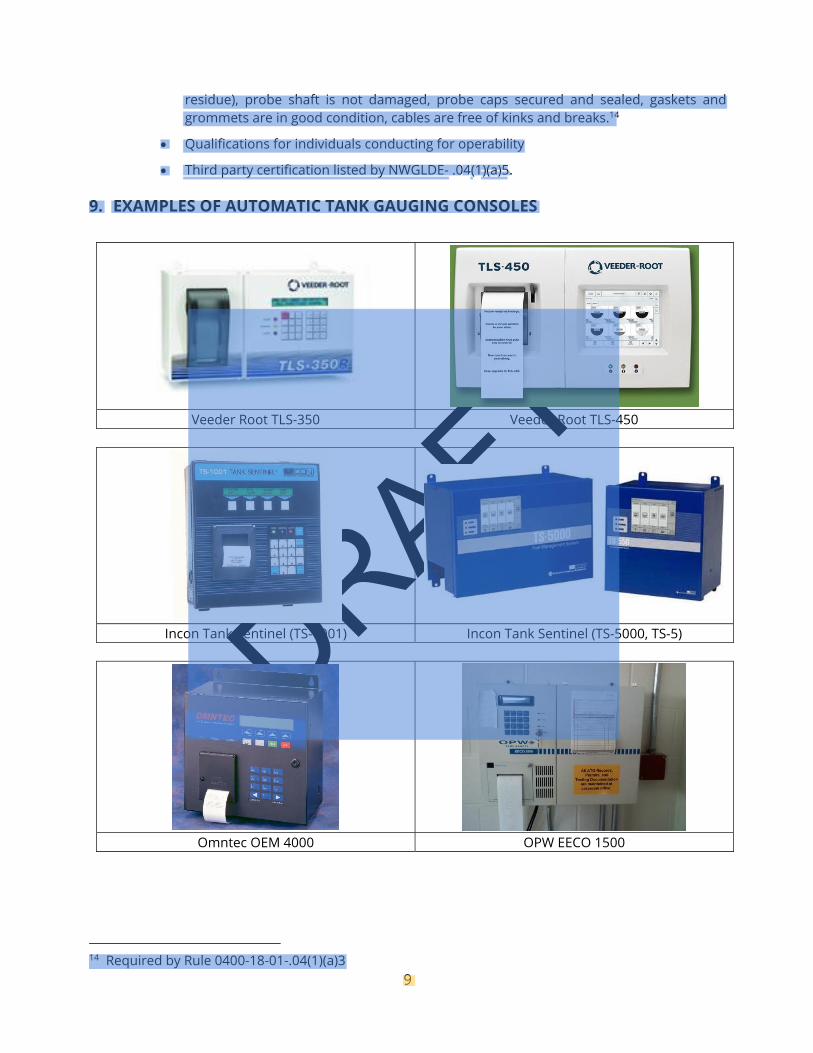
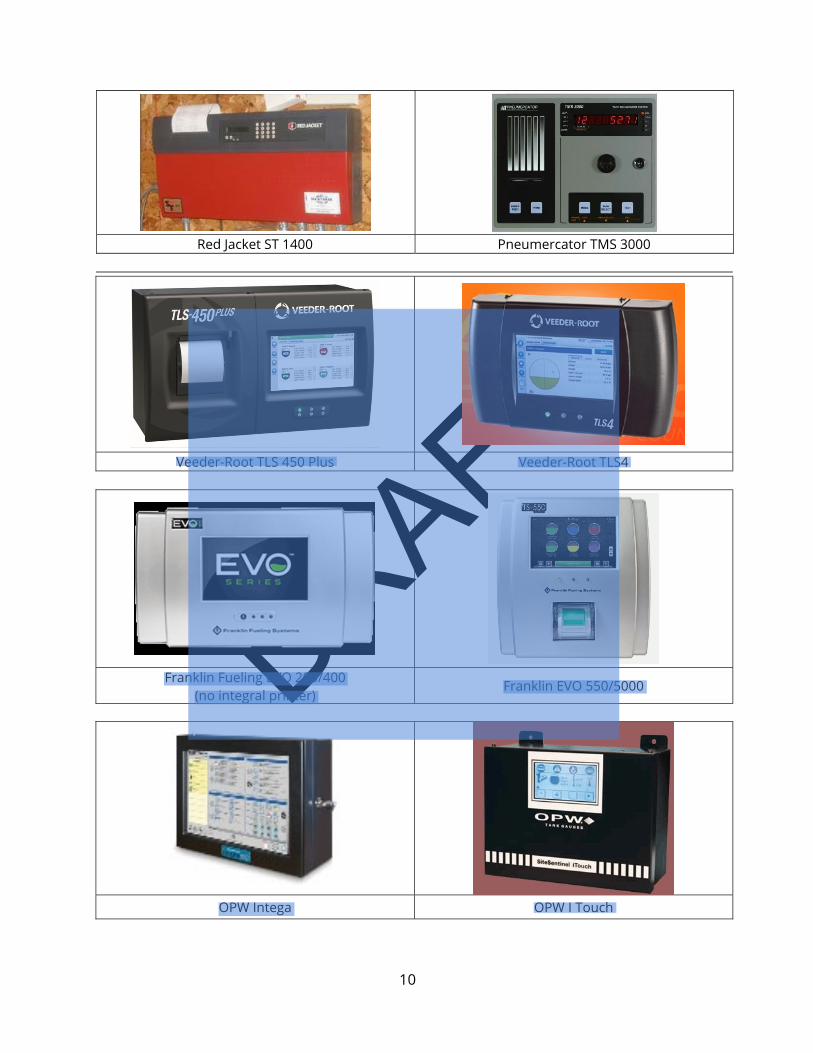
9. EXAMPLES OF AUTOMATIC TANK GAUGING CONSOLES
Veeder Root TLS-350 Veeder Root TLS-450
Incon Tank Sentinel (TS-1001) Incon Tank Sentinel (TS-5000, TS-5)
Omntec OEM 4000 OPW EECO 1500
14 Required by Rule 0400-18-01-.04(1)(a)3
DRAFT
10
Red Jacket ST 1400 Pneumercator TMS 3000
Veeder-Root TLS 450 Plus Veeder-Root TLS4
Franklin Fueling EVO 200/400 (no integral printer)
Franklin EVO 550/5000
OPW Intega OPW I Touch
DRAFT
11
10. COMMON PROBLEMS ASSOCIATED WITH ATG SYSTEMS
a. 24-Hour UST Systems High throughput or unmanned facilities frequently dispense fuel 24 hours a day and may not be capable of completing a 0.2 gph test. A common problem is that the ATG needs a minimum amount of “quiet time” where no fuel is delivered or dispensed in order to run a valid test. It may not be possible to get a valid test at a UST system open 24 hours a day. If there is adequate quiet time in a 30 day monitoring period, then this should allow the ATG system to perform a valid leak test.
b. Alarms Not Properly Investigated Owners and operators must address any alarms from the ATG system.15 During a UST Operations Inspection, Division staff should visually inspect the ATG console to verify there are no active alarms that have not been investigated. If any leak detection records are missing or incomplete, then the inspector must request a copy of the ATG system in-tank alarm history report to confirm there are no ongoing problems which require investigation. See rule .03(2). Examples of alarm history reports from various ATG consoles are shown in later sections of this technical document. Failure to properly investigate leak alarms and report suspected releases to the Division within 72 hours is a violation of rule .03(2)(a)3. and .05(1)(a)3.
15 Required by Rule 0400-18-01-.05(1)(a)3
DRAFT
12
c. Monthly Leak Test Reports Not Maintained Even if a facility is equipped with an ATG, it does not guarantee compliance. Some tank owners rely on the ATG console’s internal memory to store these records, and generate them upon request with a Leak History report. Leak history reports are acceptable, under rules .03(2)(b)11. and .04(5)(b), but electronic component failure due to electrical shortage, storms, or hardware problems frequently allow electronically stored records to be permanently lost. Therefore, it is the Division’s recommendation that owners/operators not rely on the ATG leak history for maintaining monthly release detection records. A release could go undetected if monthly records are not reviewed. An owner/operator may be unaware if the ATG fails to produce a passing monthly record. In addition, the Division recommends that ATG leak test reports be reviewed when they are printed on a monthly basis. If the leak report indicates a leak (i.e., failing test, etc.), then, in accordance with rules .03(2)(b)11., .04(3)(c)1.(ii),.04(3)(c)2.(ii), and .05(1)(a)3. the owner/operator shall report a suspected release to the Division within 72 hours.
d. Tank Owner/ Operator Unfamiliar with ATG Operation If the facility operator is not familiar with the ATG functions, then a release may go undetected. Report any monthly failed leak test results as required by rules. rules .03(2)(b)11., .04(3)(c)1.(ii),.04(3)(c)2.(ii)and .05(1)(a)3. Failure to do so may result in a civil penalty and jeopardize fund coverage for a release. The owner’s ATG manual should be available at the facility. Many ATG manuals may be downloaded from the manufacturers’ websites.
e. Tank Fuel Volume Too Low for Valid Leak Test All ATG probes are required to have a minimum product level in the tank in order to conduct a valid test in static test mode.16 It is possible for some ATG systems to produce passing results when the product level in the tank is below the minimum product level for a valid test. The Division does not consider tests conducted at insufficient product levels to be acceptable because rule .04(1)(a)2. requires methods of release detection to be “installed, calibrated, operated and maintained in accordance with the manufacturer’s instructions, including routine maintenance and service checks for operability or running condition”. The minimum product levels are specified in the NWGLDE list and the EPA ATG Reference Manual. These product levels may change based on reevaluations.
f. ATG Not Programmed Properly Specific information that may not be programmed correctly includes, but may not be limited to, tank diameter and volume, tank material of construction, product type, minimum product test level, leak detection threshold, high/low product level alarms and high water alarms. A qualified technician must reprogram these parameters if they are incorrect. Consult Technical Chapter 3.5 Requirements for Pressurized Piping for piping parameters if an electronic line leak detector is being used. Rule .04(1)(a)2. requires release detection equipment to be “installed, calibrated, operated and maintained in accordance with the manufacturer’s instructions, including routine maintenance and service checks for operability or running
16 Required by Rule 0400-18-01-.04(1)(a)5
DRAFT
13
condition”.
g. Third Party Evaluation for Large Capacity or Manifolded Tank Systems Several ATG systems have not been third party evaluated for manifolded tank systems. Each tank in a manifolded tank system is required to have a separate ATG probe unless the ATG system is also using a continuous statistical leak detection system (CSLD or SCALD). The Division will not accept leak test reports from ATG systems that are not third party certified for the tank size the ATG system is monitoring as required by rules .04(1)(a)4, .04(1)(a)5, .04(3)(c)1.(ii), and .04(3)(c)2.(ii).
h. ATG System Not Routinely Inspected Manufacturers recommend routine inspection and maintenance of equipment to ensure proper operation and detect deterioration of the probes, wiring or floats. And, ATG systems must be “maintained in accordance with the manufacturer’s instructions” as required by rule .04(1)(a)2. However, we recommend but do not require verification of routine periodic maintenance.
i. ATG Static Leak Threshold Set Incorrectly The leak threshold must be set at or less than the leak threshold value determined in the third party evaluation.17 Typically this value is 0.10 gph, but may vary depending on the equipment. Any passing test result with a leak threshold greater than the published value is an invalid test result and a qualified technician must reprogram the leak threshold to the correct value.
j. ATG used for Tank Tightness Testing ATGs may not be used for tank tightness testing because they do not consider groundwater levels as required by rule .04(3)(b)2., and are not capable of testing the ullage space.
k. Probes with Ethanol-blended Fuels Traditional water floats used on ATGs will not reliably detect water intrusion into a tank containing ethanol-blended fuels. This is problematic in that it does not provide any warning to the tank owner about increasing water content in the fuel. Although not required, tank owners are encouraged to monitor the tank at least monthly with a gauging stick and water finding paste designed for use with ethanol-blended fuels. Some floats are available that will detect the phase separation layer.
l. Submittal of Inaccurate Records Ensure records are for the correct facility. The ATG console must be accessible during the inspection and an authorized representative who is familiar with operation of the ATG system must be present to generate inventory and setup reports if a problem is identified onsite (i.e. testing at product level below third party certification, improper tank size for test) This may require a follow-up inspection with setup provided if the console could not be reprogrammed during the initial inspection as required by rule .03(2).
17 Required by Rule 0400-18-01-.04(1)(a)5
DRAFT
14
If only the tank leak test history (not monthly leak tests) was provided in records submittal, then the tank leak test history should be again printed off during the onsite inspection.
11. REASONS WHY TANK LEAK TESTS FAIL
a. An actual leak has occurred.
b. Temperature instability after product delivery Temperature variations of the product within the tank after a fuel delivery are the most common source of interference and failed leak tests/false alarms (a false positive or failure to detect an actual leak). Look at the hourly temperature data on the leak test report and retest if the variation in temperature is more than a few tenths of a degree. If leak test is being performed in static test mode, then do not begin the leak test until a sufficient period of time has passed since a fuel delivery has occurred. This period is called “waiting time” and is found in the NWGLDE listing for each ATG system.
c. ATG Tank Chart Accuracy- accuracy of 1-point profile for FRP tanks (minimum 4 point required by Veeder-Root).
d. Large changes in product temperature from the beginning to the end of the test. This could be reported as an invalid test or as a failed leak test result.
e. Water level changes from the beginning to the end of the test.
f. Tank Deformation/Deflection The tank changes shape after a large product delivery.
g. Tank Crosstalk The fuel level changes in one tank causes a level change in an adjacent tank or compartment in manifolded tanks or compartments.
h. Product is being dispensed during a leak test.
i. Equipment malfunction
12. RECORDKEEPING Rules .03(2)(b)11. and .04(5)(b) require that the previous 12 months of monthly 0.2 gph leak test results for each tank be properly maintained and be available for Division review. Annual operability testing records shall be maintained for three years. 18The Division also requires under rule .03(2), that someone who is familiar with the operation of the ATG system be present during
18 Required by Rule 0400-18-01-.04(5)(b)2

DRAFT
15
an inspection and be able to generate the following information for review to ensure the ATG system is operational:
DRAFT
16
13. TYPES OF REPORTS The following are examples of reports that may be generated.
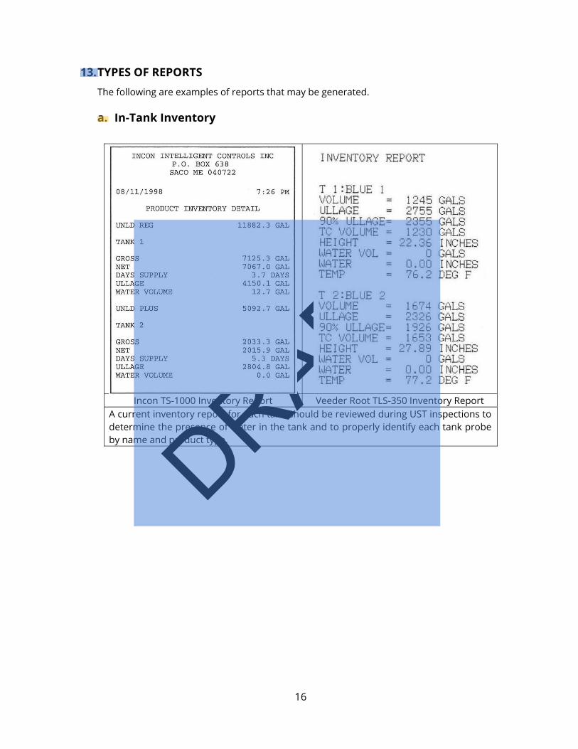
a. In-Tank Inventory
Incon TS-1000 Inventory Report Veeder Root TLS-350 Inventory Report
A current inventory report for each tank should be reviewed during UST inspections to determine the presence of water in the tank and to properly identify each tank probe by name and product type.
DRAFT
17
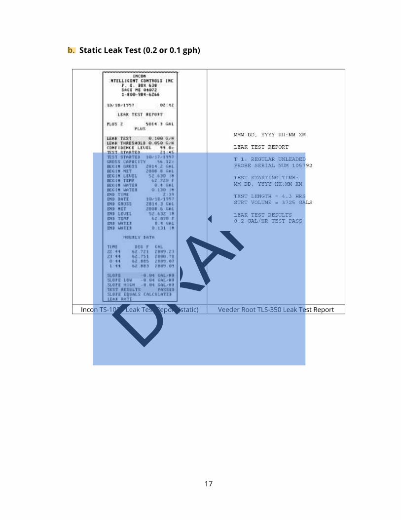
b. Static Leak Test (0.2 or 0.1 gph)
Incon TS-1000 Leak Test Report (static) Veeder Root TLS-350 Leak Test Report
DRAFT
18
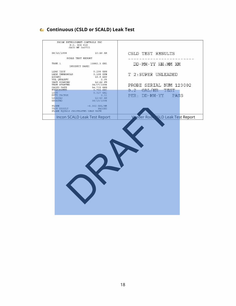
c. Continuous (CSLD or SCALD) Leak Test
Incon SCALD Leak Test Report Veeder Root CSLD Leak Test Report
DRAFT
19
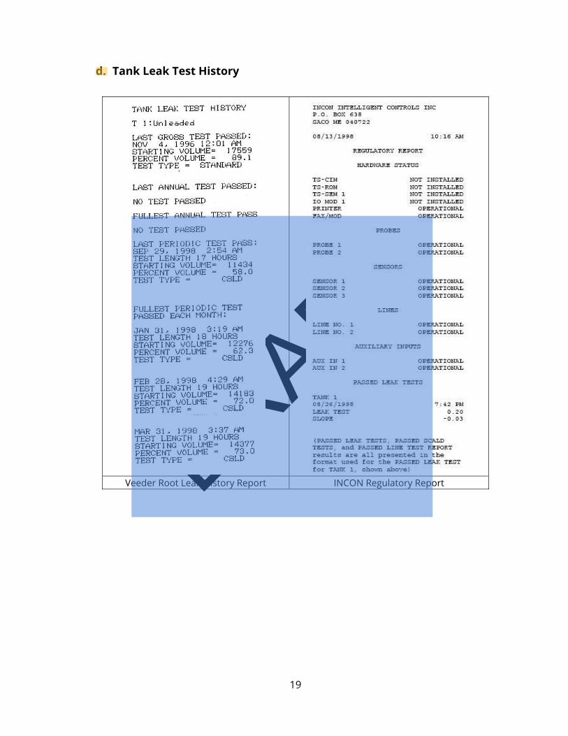
d. Tank Leak Test History
Veeder Root Leak History Report INCON Regulatory Report
DRAFT
20
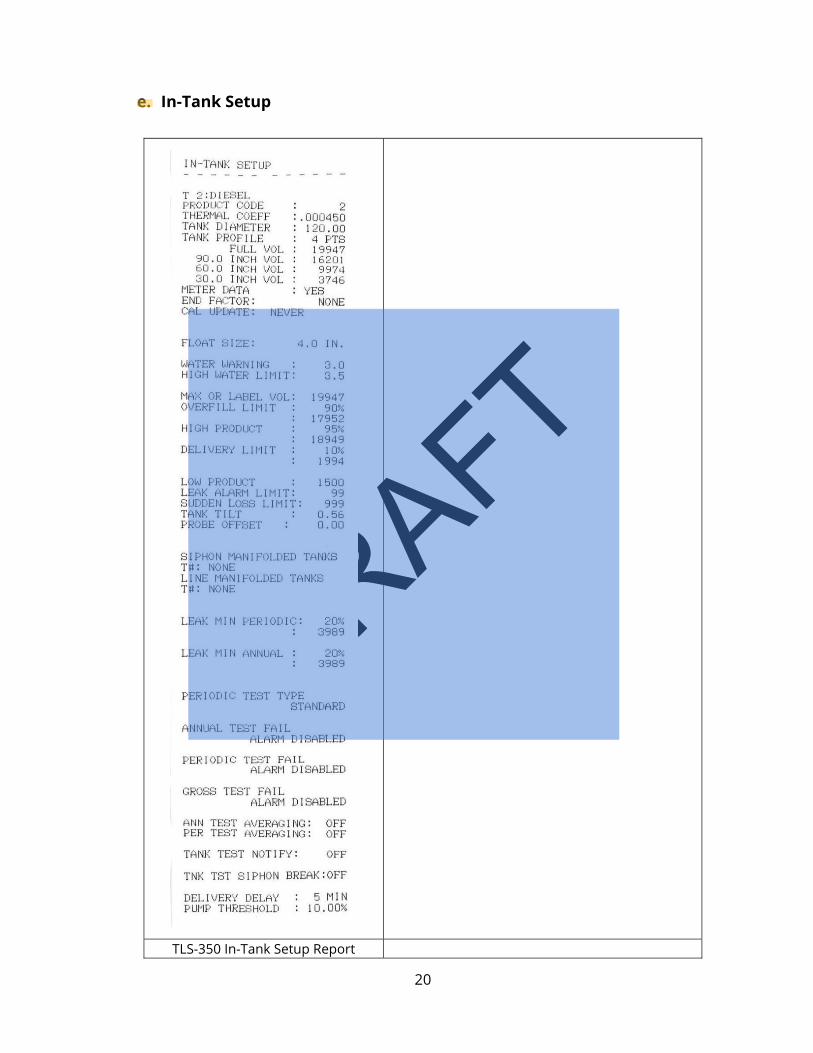
e. In-Tank Setup
TLS-350 In-Tank Setup Report
DRAFT
21
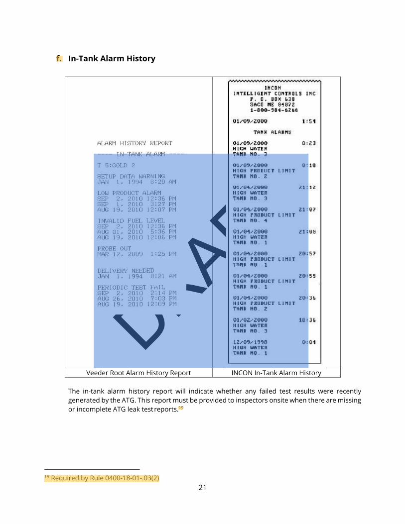
f. In-Tank Alarm History
Veeder Root Alarm History Report INCON In-Tank Alarm History
The in-tank alarm history report will indicate whether any failed test results were recently generated by the ATG. This report must be provided to inspectors onsite when there are missing or incomplete ATG leak test reports.19
19 Required by Rule 0400-18-01-.03(2)
DRAFT
22
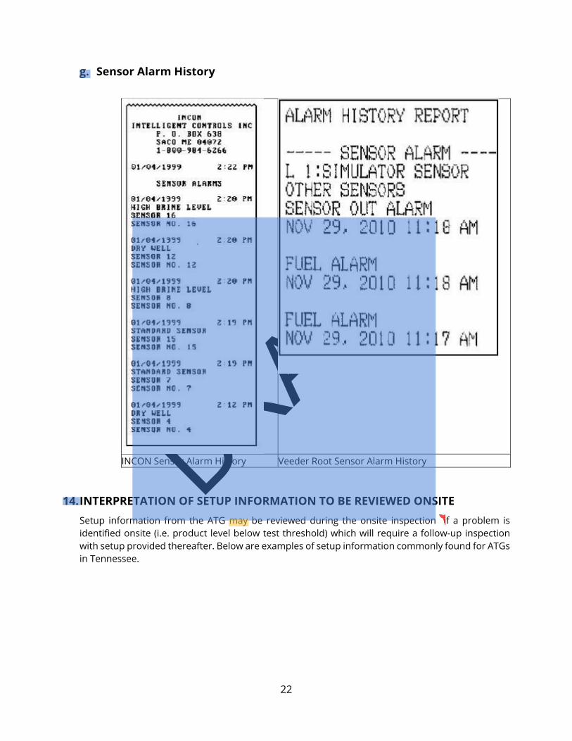
g. Sensor Alarm History
INCON Sensor Alarm History Veeder Root Sensor Alarm History
14. INTERPRETATION OF SETUP INFORMATION TO BE REVIEWED ONSITE Setup information from the ATG may be reviewed during the onsite inspection if a problem is identified onsite (i.e. product level below test threshold) which will require a follow-up inspection with setup provided thereafter. Below are examples of setup information commonly found for ATGs in Tennessee.
DRAFT
23
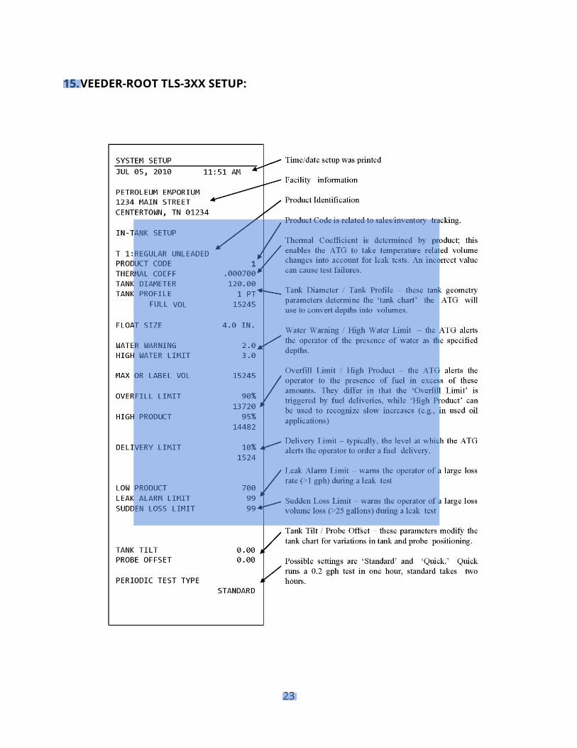
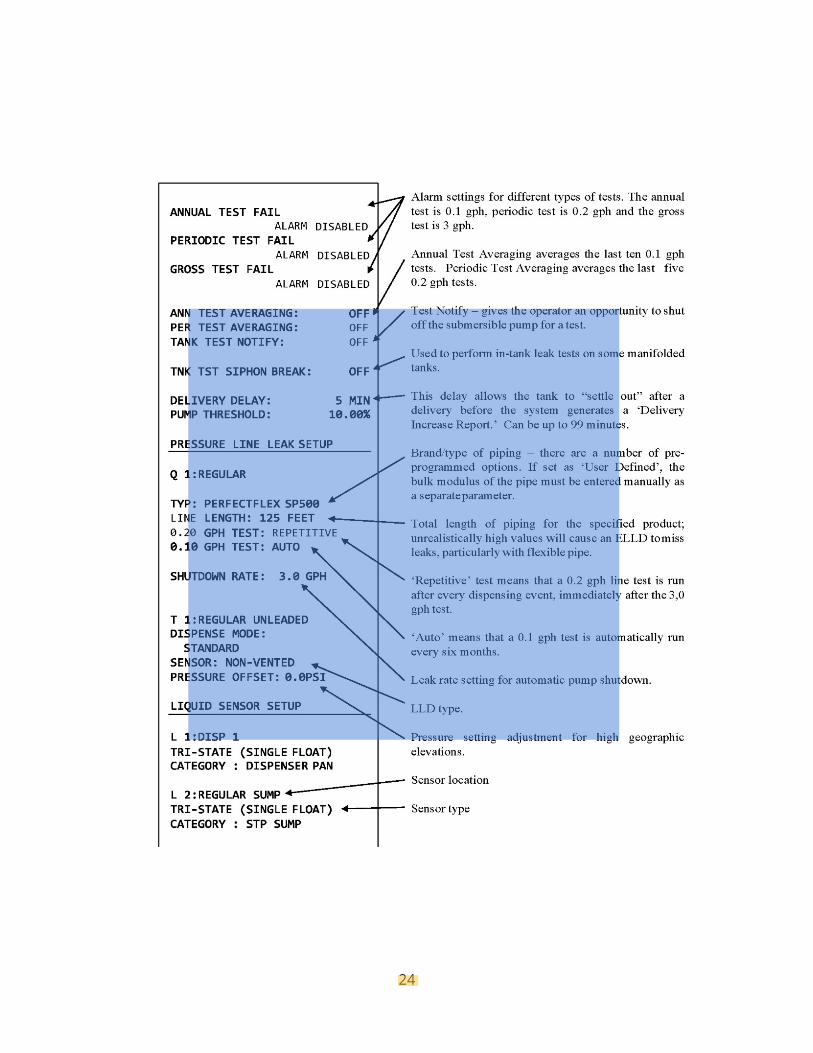
15. VEEDER-ROOT TLS-3XX SETUP:
DRAFT
24
DRAFT
25
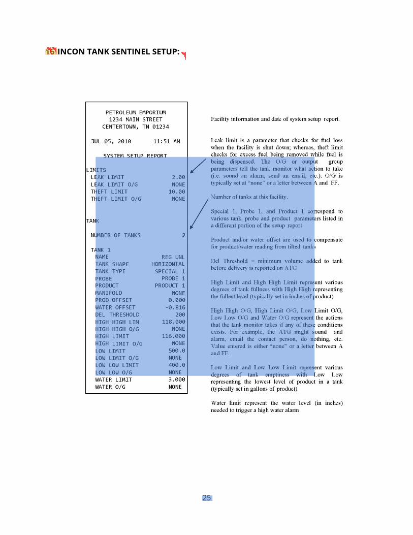
16. INCON TANK SENTINEL SETUP:
DRAFT
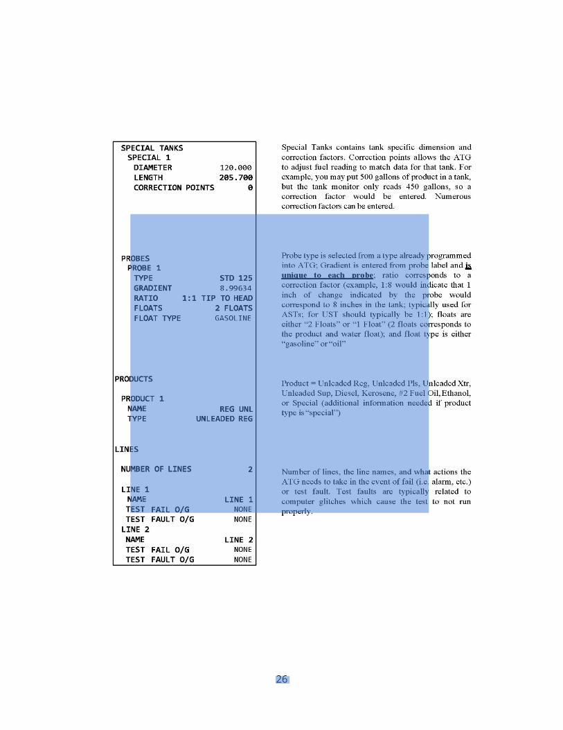
26
DRAFT
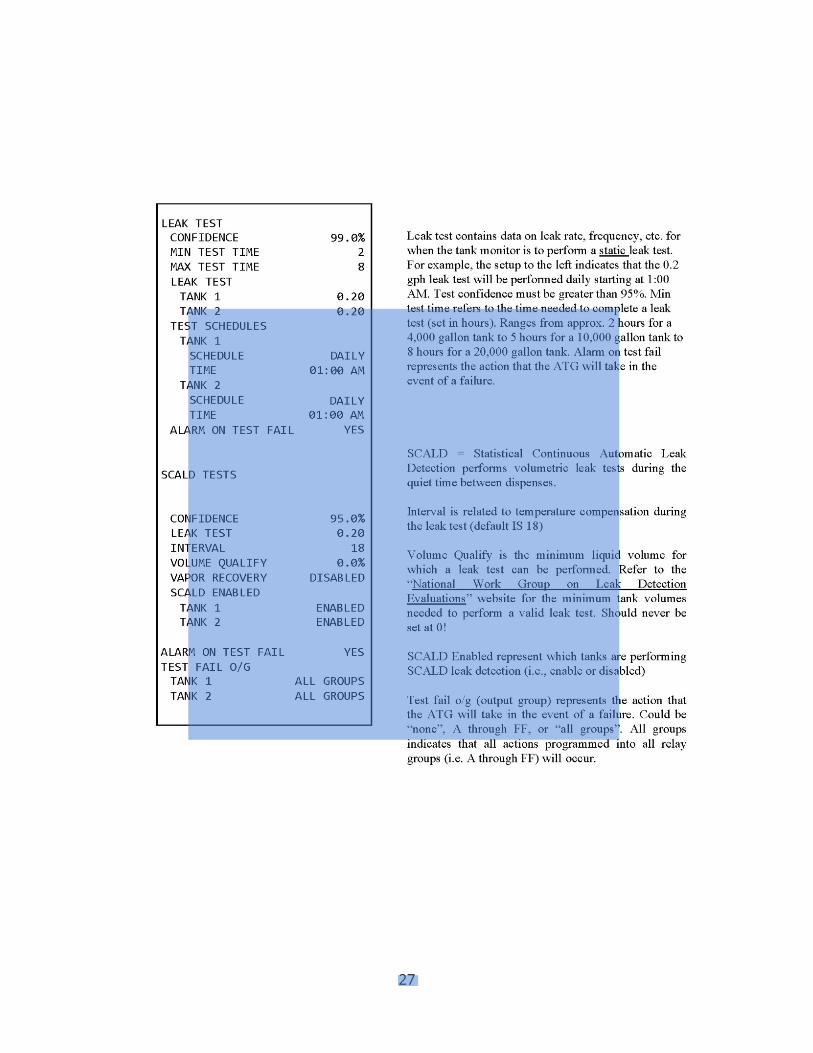
27
DRAFT
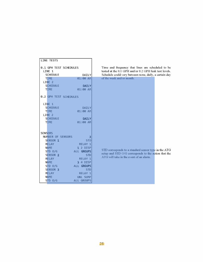
28
DRAFT
29
For Veeder Root and INCON models used for CSLD, the probability of detection can be set at 95% or 99%. Any leak detection method installed after December 22, 1990 must be capable of detecting a leak rate with a probability of detection of ninety-five (95) percent and a probability of false alarm no greater than five (5) percent, in accordance with rule .04(1)(a)4. Upon transfer of ownership, including, but not limited to, sale of the UST systems, originals and/or copies of all documents required to satisfy the reporting and recordkeeping requirements shall be transferred as required by rules .03(2)(d) and .02(7)(h), to the new owner of the USTs at the time of ownership transfer.
17. REPORTING If any of the following conditions are observed, then the Division should be contacted to report a suspected or confirmed release with 72 hours as required by rule .05(1)(a): Results of any failed 0.1 gph or 0.2 gph leak tests from the ATG, unless the monitoring device or
an associated UST component is found to be defective but not leaking, is immediately repaired, and a follow-up test does not confirm the initial result as required by rule .05(1)(a)3.
Any in-tank alarm from the ATG which indicates a sudden or unexplained loss of product as required by rule .05(1)(a)2. Documentation of investigation of all in-tank leak alarms should be kept with the ATG leak test reports for review by Division staff.20
Any released petroleum product at the UST site or in the surrounding area (such as the presence of free product, or petroleum vapors in soils, basements, sewer and utility lines and nearby surface water). See rule .05(1)(a)1.
20 Required by Rule 0400-18-01-.03(2)
DRAFT
30
REFERENCES
Automatic Tank Monitoring and Leak Detection Reference Manual, U.S. EPA, Region 7
Automatic Tank Gauging Systems for Release Detection: Reference Manual for Underground Storage Tank Inspectors, August 2000
Getting the Most Out of Your Automatic Tank Gauging System, EPA 510-F-98-011 INCON TS-5 Series Operator’s Manual
Kentucky DEP UST Inspector Handbook, May 2006 Petroleum Equipment Institute
Veeder Root TLS-3XX Operators Manual, 576013-610 Rev. AA Veeder Root TLS-3XX Installation Manual, 576013-498, Rev. B
Veeder Root TLS-3XX System Setup Manual, 576013-623, Rev. V Veeder Root TLS-3XX Troubleshooting Guide, 576013-818, Rev. AA
Veeder Root TLS Monitoring Systems Contractor’s Site Preparation Guide, 577013-578 Rev. E Wisconsin COMM 10 Material Approval # 20050005, Automatic Tank Gauging, Dec. 2009 Wisconsin COMM 10 Material Approval # 20020011, Incon Series, Dec. 2007
Underground Storage Tanks- The Basics, Iowa Department of Natural Resources, Underground Storage Tank Branch, March 2010

DRAFT
31
APPENDICES 1. ATG Leak Detection Quick Reference Table (8-27-2013) 2. Automatic Tank Gauge Operability Test Procedure

DRAFT
32
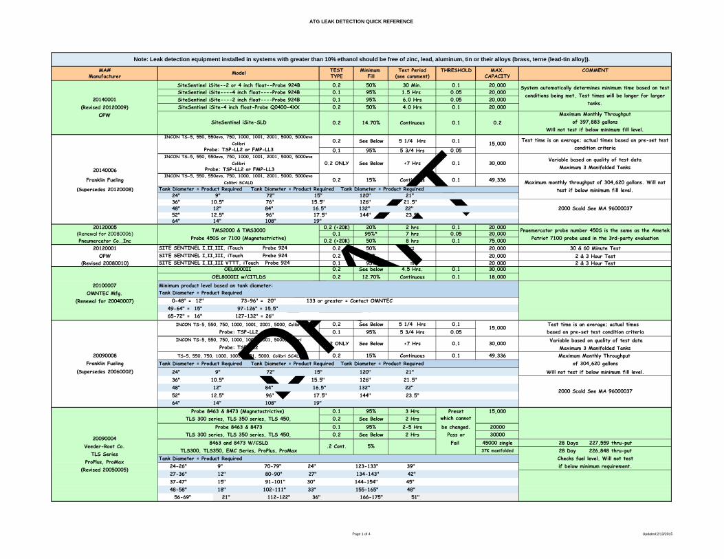
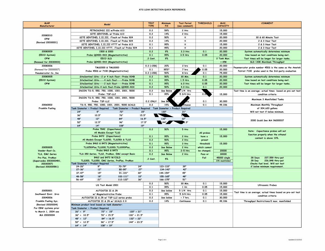
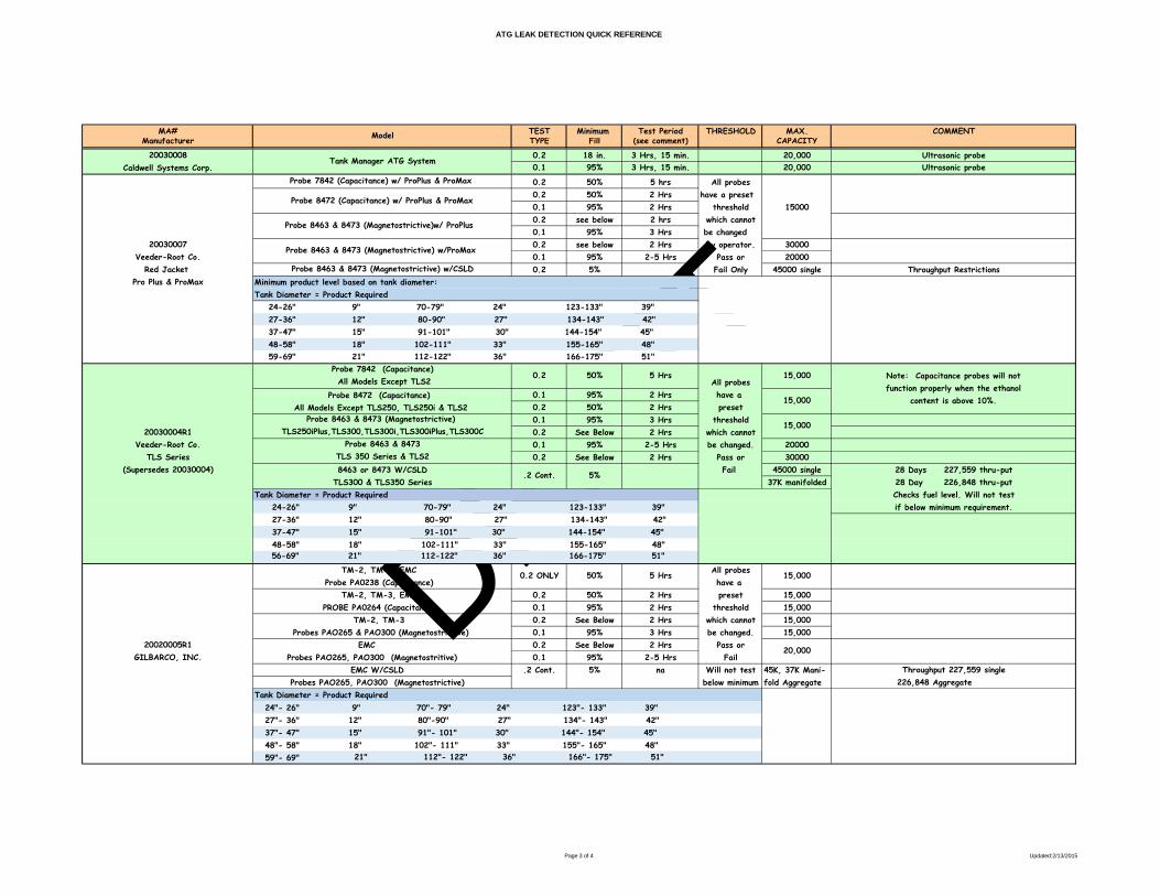
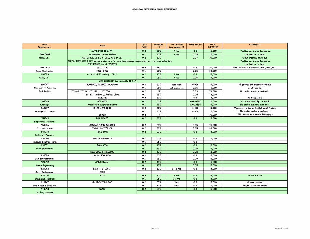
APPENDIX 1: ATG Leak Detection Quick Reference Table Updated 2-13-2015
DRAFT
ATG LEAK DETECTION QUICK REFERENCE
Page 1 of 4 Updated:2/13/2015
MA# TEST Minimum Test Period THRESHOLD MAX. COMMENTManufacturer TYPE Fill (see comment) CAPACITY
0.2 50% 30 Min. 0.1 20,0000.1 95% 1.5 Hrs 0.05 20,0000.1 95% 6.0 Hrs 0.05 20,0000.2 50% 4.0 Hrs 0.1 20,000
0.2 14.70% Continuous 0.1 0.2Maximum Monthly Throughput
of 397,883 gallonsWill not test if below minimum fill level.
0.2 See Below 5 1/4 Hrs 0.1
0.1 95% 5 3/4 Hrs 0.05
20140006
Franklin Fueling 0.2 15% Continuous 0.1 49,336
(Supersedes 20120008)
2000 Scald See MA 96000037
20120005 0.2 (<20K) 20% 2 hrs 0.1 20,000(Renewal for 20080006) 0.1 95%* 7 hrs 0.05 20,000Pneumercator Co.,Inc 0.2 (>20K) 50% 8 hrs 0.1 75,000
20120001 0.2 50% 20,000 30 & 60 Minute TestOPW 0.2 14% 20,000 2 & 3 Hour Test
(Revised 20080010) 0.1 95% 20,000 2 & 3 Hour Test0.2 See below 4.5 Hrs. 0.1 30,0000.2 12.70% Continuous 0.1 18,000
Minimum product level based on tank diameter:
0-48" = 12" 73-96" = 20" 133 or greater = Contact OMNTEC49-64" = 15" 97-126" = 15.5"65-72" = 16" 127-132" = 26"
0.2 See Below 5 1/4 Hrs 0.1 Test time is an average; actual times 0.1 95% 5 3/4 Hrs 0.05 based on pre-set test condition criteria
20090008 0.2 15% Continuous 0.1 49,336 Maximum Monthly Throughput Franklin Fueling of 304,620 gallons
(Supersedes 20060002) Will not test if below minimum fill level.
0.1 95% 3 Hrs Preset 15,0000.2 See Below 2 Hrs which cannot
0.1 95% 2-5 Hrs be changed. 200000.2 See Below 2 Hrs Pass or 30000
Fail 45000 single 28 Days 227,559 thru-put37K manifolded 28 Day 226,848 thru-put
Checks fuel level. Will not testif below minimum requirement.
56-69" 21" 112-122" 36" 166-175" 51"
Model
24-26" 9" 70-79" 24" 123-133" 39"
TLS 300 series, TLS 350 series, TLS 450,
.2 Cont. 5%
37-47" 15" 91-101" 30" 144-154" 45"48-58" 18" 102-111" 33" 155-165" 48"
24" 9" 72" 15" 120" 21" 36" 10.5" 76" 15.5" 126" 21.5"
20100007 OMNTEC Mfg.
(Renewal for 20040007)
Probe 8463 & 8473 (Magnetostrictive) TLS 300 series, TLS 350 series, TLS 450,
Probe 8463 & 8473
8463 and 8473 W/CSLD
Tank Diameter = Product Required Tank Diameter = Product Required Tank Diameter = Product Required
20090004 Veeder-Root Co.
TLS Series ProPlus, ProMax
(Revised 20050005)
64" 14" 108" 19"
TLS300, TLS350, EMC Series, ProPlus, ProMax
Note: Leak detection equipment installed in systems with greater than 10% ethanol should be free of zinc, lead, aluminum, tin or their alloys (brass, terne (lead-tin alloy)).
OEL8000II OEL8000II w/CITLDS
Tank Diameter = Product Required
0.1 30,000
27-36" 12" 80-90" 27" 134-143" 42"
TS-5, 550, 750, 1000, 1001, 2001, 5000, Colibri SCALD
15,000INCON TS-5, 550, 550evo, 750, 1000, 1001, 2001, 5000, 5000evo
Colibri
SITE SENTINEL I,II,III, iTouch Probe 924 SITE SENTINEL I,II,III, iTouch Probe 924
36" 10.5" 76" 15.5" 126" 21.5" 48" 12" 84" 16.5" 132" 22" 52" 12.5" 96" 17.5" 144" 23.5" 64" 14" 108" 19"
SITE SENTINEL I,II,III VTTT, iTouch Probe 924
See Below
15,000Probe: TSP-LL2
INCON TS-5, 550, 750, 1000, 1001, 2001, 5000, Colibri
<7 Hrs
20140001 (Revised 20120009)
OPW
SiteSentinel iSite--2 or 4 inch float--Probe 924BSiteSentinel iSite----4 inch float----Probe 924BSiteSentinel iSite----2 inch float----Probe 924BSiteSentinel iSite-4 inch float-Probe Q0400-4XX
0.1 Probe: TSP-LL2 or FMP-LL3
SiteSentinel iSite-SLD
Probe: TSP-LL2 or FMP-LL3
Test time is an average; actual times based on pre-set test condition criteria
INCON TS-5, 550, 550evo, 750, 1000, 1001, 2001, 5000, 5000evo Colibri 0.2 ONLY See Below <7 Hrs
Maximum monthly throughput of 304,620 gallons. Will not test if below minimum fill level.
24" 9" 72" 15" 120" 21"
System automatically determines minimum time based on test conditions being met. Test times will be longer for larger
tanks.
Pnuemercator probe number 450S is the same as the Ametek Patriot 7100 probe used in the 3rd-party evaluation
TMS2000 & TMS3000 Probe 450S or 7100 (Magnetostrictive)
Variable based on quality of test dataMaximum 3 Manifolded Tanks
INCON TS-5, 550, 550evo, 750, 1000, 1001, 2001, 5000, 5000evo Colibri SCALD
Tank Diameter = Product Required Tank Diameter = Product Required Tank Diameter = Product Required
30,000
Tank Diameter = Product Required
2000 Scald See MA 96000037
Variable based on quality of test dataMaximum 3 Manifolded TanksProbe: TSP-LL2
INCON TS-5, 550, 750, 1000, 1001, 2001, 5000, Colibri 0.2 ONLY
48" 12" 84" 16.5" 132" 22" 52" 12.5" 96" 17.5" 144" 23.5"
DRAFT
ATG LEAK DETECTION QUICK REFERENCE
Page 2 of 4 Updated:2/13/2015
MA# TEST Minimum Test Period THRESHOLD MAX. COMMENTManufacturer TYPE Fill (see comment) CAPACITYModel
0.2 59% 2 Hrs 15,0000.2 14% 2 Hrs 15,0000.2 50% 20,000 30 & 60 Minute Test0.2 14% 20,000 2 & 3 Hour Test0.1 95% 15,000 2 & 3 Hour Test0.1 95% 20,000 2 & 3 Hour Test
20080009 0.2 9% 3.3 Hrs 0.1 20,000 System automatically determines minimum(EECO System) 0.1 95% 3.5 Hrs 0.05 20,000 time based on test conditions being met.
OPW .2 Cont. 9% 2 Tank Max. Test times will be longer for larger tanks.(Renewal for 20030003) <=35K SLD 130K Maximum Throughput
20080006 0.2 (<20K) 20% 2 hrs 0.1 20,000(Renewal for 20000007) 0.1 95%* 7 hrs 0.05 20,000Pneumercator Co.,Inc 0.2 (>20K) 50% 8 hrs 0.1 75,000
20080005 0.2 50% 30 Min. 0.1 20,000 System automatically determines minimum(EECO System) 0.1 95% 1.5 Hrs 0.05 20,000 time based on test conditions being met.
OPW 0.1 95% 6.0 Hrs 0.05 20,000 Test times will be longer for larger tanks.0.2 50% 4.0 Hrs 0.1 20,0000.2 See Below 5 1/4 Hrs 0.10.1 95% 5 3/4 Hrs 0.05
20060002 0.2 15% Continuous 0.1 49,336 Maximum Monthly Throughput Franklin Fueling of 304,620 gallons
Will not test if below minimum.
0.2 50% 5 Hrs 15,000All probes
0.1 95% 2 Hrs have a 15,0000.2 50% 2 Hrs preset0.1 95% 3 Hrs threshold 15,000
20050005 0.2 See Below 2 Hrs which cannotVeeder-Root Co. 0.1 95% 2-5 Hrs be changed. 20000TLS, EMC Series 0.2 See Below 2 Hrs Pass or 30000Pro Plus, ProMax Fail 45000 single 28 Days 227,559 thru-put
(Supercedes 20030004R1, 37K manifolded 28 Day 226,848 thru-put20030007) Checks fuel level. Will not test
(Revised 2002005R1) if below minimum requirement.
56-69" 21" 112-122" 36" 166-175" 51"
0.2 50% 30 Min. 0.1 15,0000.1 95% 1 Hr. 0.05 15,000
20050001 0.2 See below 5 1/4 Hrs 0.1 15,000Southwest Envir. Srvs 0.1 95% 5 3/4 Hrs 0.05 15,000
20040006 0.2 See below < 7 hrs. 0.1 30,000Franklin Fueling Sys. 0.2 14% Continuous 0.1 49,336 Throughput Restrictions/2 max. manifolded(Revised 20020004) Minimum product level based on tank diameter:
For EBW systems prior Tank Diameter = Product Required to March 1, 2004 see 26" = 9" 72" = 15" 120" = 21"
MA 20020004 36" = 10.5" 76" = 15.5" 126" = 21.5" 48" = 12" 84" = 16.5" 132" = 22" 52" = 12.5" 96" = 17.5" 144" = 23.5" 64" = 14" 108" = 19"
20080010 OPW
(Revised 20030001)
Probe Q0400-4XX (Magnetostrictive)
48-58" 18" 102-111" 33" 155-165" 48"
SITE SENTINEL w/ Probe 613
All Models Except TLS2
Probe Q0400-4XX (Magnetostrictive)
30,000
EECO SLD
SITE SENTINEL I,II,III, iTouch w/ Probe 924
Tank Diameter = Product Required Tank Diameter = Product Required Tank Diameter = Product Required
SITE SENTINEL I,II,III VTTT w/ Probe 613
15,000Probe: TSP-LL2
<7 Hrs 0.1
Probe 7842 (Capacitance)
SITE SENTINEL I,II,III VTTT, iTouch w/ Probe 924
INCON TS-5, 550, 750, 1000, 1001, 2001, 5000
AUTOSTIK II & JR w/ TSP-LL2 series probe AUTOSTIK II & JR w/ SCALD 2.0
24-26" 9" 70-79" 24" 123-133" 39"
See Below
8463 and 8473 W/CSLD
Tank Diameter = Product Required
Note: Capacitance probes will not function properly when the ethanol
content is above 10%.
1500 & 2000
36" 10.5" 76" 15.5" 126" 21.5"
TS-5, 550, 750, 1000, 1001, 2001, 5000 SCALD
All Models Except TLS250, TLS250i & TLS2
24" 9" 72" 15" 120" 21"
SITE SENTINEL I,II,III, iTouch w/ Probe 924
27-36" 12" 80-90" 27" 134-143" 42"
Test time is an average; actual times based on pre-set test condition criteria
AUTOSTIK II & JR
Maximum 3 Manifolded Tanks Probe: TSP-LL2
INCON TS-5, 550, 750, 1000, 1001, 2001, 5000
.2 Cont.
Probe 8463 & 8473 (Magnetostrictive)
SiteSentinel iSite--2 or 4 inch float--Probe 924BSiteSentinel iSite----4 inch float----Probe 924BSiteSentinel iSite----2 inch float----Probe 924B
Pnuemercator probe number 450S is the same as the Ametek Patriot 7100 probe used in the 3rd-party evaluation
TMS2000 & TMS3000 Probe 450S or 7100 (Magnetostrictive)
2000 Scald See MA 96000037
0.2 ONLY
37-47" 15" 91-101" 30" 144-154" 45"
PETROSONIC III w/Probe 613
Probe 8463 & 8473
Ultrasonic ProbesUS Test Model 2001
Test time is an average; actual times based on pre-set test condition criteria
SiteSentinel iSite-4 inch float-Probe Q0400-4XX
TLS250iPlus,TLS300,TLS300i,TLS300iPlus,
48" 12" 84" 16.5" 132" 22" 52" 12.5" 96" 17.5" 144" 23.5" 64" 14" 108" 19"
TLS 350 Series, TLS2, ProMax, EMC except Basic
w/ Magnetostrictive Probe
5%TLS300, TLS350, EMC Series, ProPlus, ProMax
Probe 8472 (Capacitance)
DRAFT
ATG LEAK DETECTION QUICK REFERENCE
Page 3 of 4 Updated:2/13/2015
MA# TEST Minimum Test Period THRESHOLD MAX. COMMENTManufacturer TYPE Fill (see comment) CAPACITYModel
20030008 0.2 18 in. 3 Hrs, 15 min. 20,000 Ultrasonic probeCaldwell Systems Corp. 0.1 95% 3 Hrs, 15 min. 20,000 Ultrasonic probe
0.2 50% 5 hrs All probes0.2 50% 2 Hrs have a preset0.1 95% 2 Hrs threshold 150000.2 see below 2 hrs which cannot0.1 95% 3 Hrs be changed
20030007 0.2 see below 2 Hrs by operator. 30000Veeder-Root Co. 0.1 95% 2-5 Hrs Pass or 20000
Red Jacket 0.2 5% Fail Only 45000 single Throughput RestrictionsPro Plus & ProMax Minimum product level based on tank diameter:
Tank Diameter = Product Required 24-26" 9" 70-79" 24" 123-133" 39" 27-36" 12" 80-90" 27" 134-143" 42" 37-47" 15" 91-101" 30" 144-154" 45" 48-58" 18" 102-111" 33" 155-165" 48" 59-69" 21" 112-122" 36" 166-175" 51"
All probes0.1 95% 2 Hrs have a 0.2 50% 2 Hrs preset0.1 95% 3 Hrs threshold
20030004R1 0.2 See Below 2 Hrs which cannotVeeder-Root Co. 0.1 95% 2-5 Hrs be changed. 20000
TLS Series 0.2 See Below 2 Hrs Pass or 30000(Supersedes 20030004) Fail 45000 single 28 Days 227,559 thru-put
37K manifolded 28 Day 226,848 thru-putTank Diameter = Product Required Checks fuel level. Will not test 24-26" 9" 70-79" 24" 123-133" 39" if below minimum requirement. 27-36" 12" 80-90" 27" 134-143" 42" 37-47" 15" 91-101" 30" 144-154" 45" 48-58" 18" 102-111" 33" 155-165" 48" 56-69" 21" 112-122" 36" 166-175" 51"
All probeshave a
0.2 50% 2 Hrs preset 15,0000.1 95% 2 Hrs threshold 15,0000.2 See Below 2 Hrs which cannot 15,0000.1 95% 3 Hrs be changed. 15,000
20020005R1 0.2 See Below 2 Hrs Pass orGILBARCO, INC. 0.1 95% 2-5 Hrs Fail
.2 Cont. 5% na Will not test 45K, 37K Mani- Throughput 227,559 singlebelow minimum fold Aggregate 226,848 Aggregate
59"- 69"
Note: Capacitance probes will not function properly when the ethanol
content is above 10%.
All Models Except TLS2
Probe 8463 & 8473 (Magnetostrictive)w/ ProPlus
Probe 8463 & 8473 (Magnetostrictive) w/ProMax
0.2
All Models Except TLS250, TLS250i & TLS2
Probe 8463 & 8473 (Magnetostrictive) w/CSLD
5%
Probe 7842 (Capacitance)50%
TM-2, TM-3
Probe 8463 & 8473 (Magnetostrictive)
15,000
15,000
5 Hrs
.2 Cont.
15,000Probe PA0238 (Capacitance)
TLS250iPlus,TLS300,TLS300i,TLS300iPlus,TLS300C
Probe 8472 (Capacitance)
TM-2, TM-3, EMC PROBE PA0264 (Capacitance)
TM-2, TM-3, EMC
TLS 350 Series & TLS2Probe 8463 & 8473
TLS300 & TLS350 Series
0.2 ONLY
8463 or 8473 W/CSLD
50%
20,000Probes PAO265, PAO300 (Magnetostritive)
27"- 36" 12" 80"-90" 27" 134"- 143" 42" 37"- 47" 15" 91"- 101" 30" 144"- 154" 45" 48"- 58" 18" 102"- 111" 33" 155"- 165" 48"
Tank Diameter = Product Required
21" 112"- 122" 36" 166"- 175" 51"
Probes PAO265 & PAO300 (Magnetostrictive) EMC
EMC W/CSLD Probes PAO265, PAO300 (Magnetostrictive)
24"- 26" 9" 70"- 79" 24" 123"- 133" 39"
5 Hrs 15,000
Tank Manager ATG System
Probe 8472 (Capacitance) w/ ProPlus & ProMax
Probe 7842 (Capacitance) w/ ProPlus & ProMax
DRAFT
ATG LEAK DETECTION QUICK REFERENCE
Page 4 of 4 Updated:2/13/2015
MA# TEST Minimum Test Period THRESHOLD MAX. COMMENTManufacturer TYPE Fill (see comment) CAPACITYModel
0.2 50% 4 hrs 0.1 15,000 Testing can be performed on20020004 0.1 95% 4 hrs 0.05 15,000 one tank at a time.EBW, Inc. 0.2 30% 0.07 30,000 <150K Monthly thru-put
NOTE: EBW 970 & 973 series probes are for inventory measurements only, not for leak detection. Testing can be performed onone tank at a time.
20010019 0.2 14% 0.1 20,000 See 20030003 for EECO 1500,2000,SLDEmco Electronics 0.1 95% 0.05 20,000
990053 0.2 10% 4 hrs 0.1 15,000EBW, Inc. 0.1 95% 4 hrs 0.05 15,000
990047 0.2 50% Test time 0.058 15,000 All probes are magnetostrictiveThe Marley Pump Co. 0.1 95% not available. 0.05 15,000 or ultrasonic.
Red Jacket 0.2 15" 0.09 73,500 No probe numbers available.0.1 95% 0.05 73,5000.2 50% 0.1 18,000 PC Compatible
960043 0.2 50% VARIABLE 15,000 Tests are manually initiated.OMNTEC 0.1 95% VARIABLE 15,000 No probe numbers available.960037 0.2 50% 0.058 15,000 Magnetostrictive or Digital Level Probes
Intelligent Controls 0.1 95% 0.058 15,000 No probe numbers available.0.2 7% 30,000 108K Maximum Monthly Throughput
950069 0.2 90% 0.1 15,000Engineered Systems
950056 0.2 50% 0.05 75,000P C Interactive 0.2 20% 0.05 30,000
940078 0.2 90% 0.1 15,000Universal Sensors
930080 0.2 50% 0.2 15,000Andover Controls Corp. 0.1 95% 0.1
930071 0.2 15% 0.1 15,000Tidel Engineering 0.1 95% 0.05 15,000
0.2 50% 0.05 15,000930058 0.2 50% 0.1 15,000
L&J Environmental 0.1 95% 0.05 15,000920092 0.2 10% 0.1 15,000
Ronan Engineering 0.1 95% 0.05 15,000920052 0.2 50% 1-15 hrs 0.1 15,000
Alert Technologies920030 0.2 10% 6 hrs 0.2 15,000 Probe #7030
MagneTek Controls 0.1 95% 12 hrs 0.1 15,000910107 0.2 50% 3hrs 0.2 15,000 Unknown probes.
Wm.Wilson's Sons Inc. 0.1 95% 9hrs 0.1 15,000 Magnetostrictive Probe910093 0.2 90% 0.1 15,000
Mallory Controls
RLM5000, RLM5001,RLM9000
w/ 960/961 Series ProbesAUTOSTIK II & JR CSLD v31 or v51
SEE 990053 for AUTOSTIK
AUTOSTIK II & JR
ST1400, ST1401,ST 1401L, ST1800,ST1801, St1801L, Prolink Ultra
Autostik (950 series) ONLY
SEE 20020004 for Autostik II & Jr
EECO TLM1000, 3000
PROLINK OEL 8000
Probes are MagnetostrictiveINCON TS 2000
SCALD
MCG 1100,8100
API/RONAN
TICS 1000
ESI IMAGE
AINLAY TANK MASTERTANK MASTER JR
7021
TMU & INFINITY
EMS 3500
EMS 2000 & EMS3000
GASBOY TMS 500
IMAGE
SMART STICK I 2000
DRAFT
33
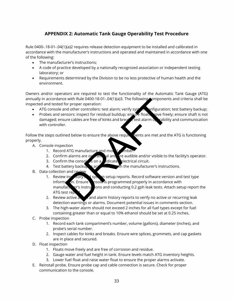
APPENDIX 2: Automatic Tank Gauge Operability Test Procedure Rule 0400-.18-01-.04(1)(a)2 requires release detection equipment to be installed and calibrated in accordance with the manufacturer’s instructions and operated and maintained in accordance with one of the following:
The manufacturer’s instructions; A code of practice developed by a nationally recognized association or independent testing
laboratory; or Requirements determined by the Division to be no less protective of human health and the
environment.
Owners and/or operators are required to test the functionality of the Automatic Tank Gauge (ATG) annually in accordance with Rule 0400-18-01-.04(1)(a)3. The following components and criteria shall be inspected and tested for proper operation:
ATG console and other controllers: test alarm; verify system configuration; test battery backup; Probes and sensors: inspect for residual buildup; ensure floats move freely; ensure shaft is not
damaged; ensure cables are free of kinks and breaks; test alarm operability and communication with controller.
Follow the steps outlined below to ensure the above requirements are met and the ATG is functioning properly.
A. Console inspection 1. Record ATG manufacture and model number. 2. Confirm alarms are operational and are audible and/or visible to the facility’s operator. 3. Confirm the console is on a dedicated electrical circuit. 4. Test battery backup in accordance with the manufacturer’s instructions.
B. Data collection and review 1. Review inventory and system setup reports. Record software version and test type
information. Ensure console is programmed properly in accordance with manufacturer’s instructions and conducting 0.2 gph leak tests. Attach setup report the ATG test report.
2. Review active alarm and alarm history reports to verify no active or recurring leak detection warnings or alarms. Document potential issues in comments section.
3. The high-water alarm should not exceed 2 inches for all fuel types except for fuel containing greater than or equal to 10% ethanol should be set at 0.25 inches.
C. Probe inspection 1. Record each tank compartment’s number, volume (gallons), diameter (inches), and
probe’s serial number. 2. Inspect cables for kinks and breaks. Ensure wire splices, grommets, and cap gaskets
are in place and secured. D. Float inspection
1. Floats move freely and are free of corrosion and residue. 2. Gauge water and fuel height in tank. Ensure levels match ATG inventory heights. 3. Lower fuel float and raise water float to ensure the proper alarms activate.
E. Reinstall probe. Ensure probe cap and cable connection is secure. Check for proper communication to the console.

file://NoURLProvided[1/23/2021 1:16:01 PM]
Summary
Shows Replacements
Shows Insertions
Shows Deletions
174Total Changes

1

2
This page left intentionally blank

3
STATE OF TENNESSEE
DEPARTMENT OF ENVIRONMENT AND CONSERVATION
DIVISION OF UNDERGROUND STORAGE TANKS
TECHNICAL CHAPTER 3.2
AUTOMATIC TANK GAUGING
EFFECTIVE DATE: October 1, 2015
PURPOSE
The purpose of this technical chapter is to assist Division of Underground Storage Tanks (Division)
staff in understanding the regulatory requirements for the operation, features, release detection,
and record keeping requirements for underground storage tank (UST) systems which utilize
Automatic Tank Gauging (ATG) for leak detection.
This technical chapter contains the current policy of the Division based on the statute and
regulations governing the Tennessee Petroleum Underground Storage Tank program.
AUTHORITY
All rules referred to in this technical chapter are contained in Chapter 0400-18-01 and are available
on the Division of Underground Storage Tanks website at
http://www.state.tn.us/sos/rules/0400/0400-18/0400-18-01.20130121.pdf
APPLICABILITY
This document provides technical and specific industry knowledge regarding the operation,
maintenance, and release detection requirements for UST systems equipped with ATG systems. The
document also provides recommended practices for inspection, discussion of common problems
associated with ATG systems, and a discussion of the most common types of ATG systems utilized at
UST facilities.
Each ATG system must be evaluated by a third party and subsequently listed by the National
Work Group on Leak Detection Evaluations (NWGLDE). All ATG systems must be third party
certified to test for leaks at 0.2 gph on a monthly basis, with a 95% probability of detection,
with no more than a 5% probability of false alarm as required by rule .04(1)(a)3. The NWGLDE
evaluations list may be accessed at www.nwglde.org

4
INTRODUCTION
ATG systems were originally developed by petroleum tank system manufacturers as a method of
determining the amount of fuel in a tank without the use of a tank gauging stick. The earliest
versions of ATGs were essentially gauging sticks which a facility operator could use to determine
how much fuel was present in a UST system. These readings were used to conduct monthly
inventory control and no additional leak testing was conducted. As technology advanced, additional
features were incorporated into the device. Water level measurements, product temperature, leak
alarms, and eventually in-tank leak detection was developed and included by the Environmental
Protection Agency (EPA) for use as a leak detection method.
Today there are numerous manufacturers which produce ATG systems, each with its own features
and benefits. As technology in the petroleum industry has advanced, most modern UST facilities are
now equipped with an ATG which can measure liquid levels within an accuracy of 1/1000th
of an
inch.
ATG systems consist of a tank probe mechanism installed in the tank that records information such
as product level and temperature and a control panel inside the facility. The control panel is
essentially a computer that communicates with the probes in one or multiple tank(s) as well as any
sensors connected to it. The ATG console collects, interprets, and analyzes the information from the
probes. Information from the ATG console is communicated to the operator via on-site or remote
printer, audible/visual alarms, or a display monitor. Most ATG systems are capable of measuring the
following:

5
Gross volume- the volume of product in the tank based on the product depth and
the tank’s depth to volume conversion factor.
Product temperature- the average temperature of product in the tank.
Net volume- temperature-compensated volume of product (calculated at 60
degrees Fahrenheit).
Water level- the amount of water in the tank in inches/gallons.
Product level- amount of the product in the tank in inches/gallons.
Ullage- the capacity of the tank minus the gross volume of product, or empty
space above the product level (usually expressed in gallons).
Net delivered product volume- an automatic calculation of delivery volume
based on before and after product level and temperature measurements. This
volume is temperature compensated to 60 degrees F of product delivered.
Leak test result- the results of the most recent as well as past leak tests. The
result of a leak test may be PASS, FAIL, INVALID, INCREASE, or TEST ABORTED, etc.
Some ATG systems may include the term SLOPE which is equivalent to the
calculated leak rate.
ATG systems can be programmed to send audible/visual alarms when various conditions exist. Most
models include the following alarms:
It is important to mention that the figure above showing a high water warning at 1”-1.5” is for fuels
with no alcohol content. According to the Tennessee Kerosene and Motor Fuel Quality Regulations
“...no water phase greater than 6 millimeters (1/4 in) as determined by an appropriate detection paste, is
allowed to accumulate in any tank utilized in the storage of gasoline-alcohol blend, biodiesel, biodiesel
blends, ethanol-flex fuel, aviation gasoline, and aviation turbine fuel.” Rule 0800-12-05-.04 (1)

6
DEFINITIONS:
Continuous In-Tank Leak Detection System (CITLDS): acronym used by Warren Rogers Associates for
CITLDS, which is a third party approved leak detection method utilizing an ATG to collect multiple
points of data for in-tank leak detection at high throughput facilities. The advantage of using CITLDS
is that tank systems do not have to be taken out of service each month to conduct a static test.
Please see Technical Chapter 3.3 Statistical Inventory Reconciliation for more detailed information
on this method.
Continuous Statistical Leak Detection (CSLD): another term also used to refer to continuous ATG
systems.
Leak Rate: a positive number expressed in gallons per hour (gph), measured by the test device that
indicates the amount of product that may be leaking out of the tank system. A negative number
may indicate that something was being added to the tank (delivery) or may be caused by a thermal
effect due to product expansion.
Leak Threshold: the measured leak rate at which an ATG system determines the tank to be leaking.
The leak threshold will always be less than or equal to the leak rate requirement for the ATG system.
For typical ATG systems, the leak rate is set at 0.2 gph and the leak threshold is set at the leak
threshold value determined in the third party evaluation.
Quiet Time: amount of time between dispensing when continuous leak test data is collected.
Statistical Continuous Automatic Leak Detection (SCALD): another term used for continuous ATG
systems used by Franklin Fueling (INCON).
Tank Capacity: the volume of product a tank will hold in gallons. Tank capacities are reported as
“nominal” capacities which means the true capacity may be smaller or larger due to allowable
tolerances in manufacturers’ processes.
Test Period: the length of the leak test as determined by the third party evaluation. This is only
applicable to static testing.
Ullage: the portion of unfilled space above the liquid level in an underground storage tank, usually
expressed in gallons.
Waiting Time: minimum amount of time after fuel deliveries before a leak test can begin.
90% Ullage: tank specific fuel level that the ATG system uses as a target threshold to ensure that
tank overfills do not occur. This level is set at 90% of the entire tank capacity.
COMPONENTS OF AUTOMATIC TANK GAUGING SYSTEMS
1) Console- see photos on page 9.
2) Probe Types

7
For these types of ATG systems to operate properly, all leak tests must be performed during
a period when no fuel is added to or removed from the tank.
a. Magnetostrictive
A magnetostrictive probe works on the principle that sound maintains a constant
velocity despite temperature differences that may occur along its route of travel.
When this principle is employed in an ATG system, a vertical pipe is installed in the
tank. A wire runs down the center of the full length of the pipe. Around the outside
of the pipe is a doughnut-shaped float that contains a strong magnet. Magnetic flux
from this floating magnet impinges on the wire at the liquid level in the tank. For
measurement of this level, a sound wave is injected into the top end of the wire and
when the sound wave reaches the level of the magnetic float, the vibration of the
wire causes electricity to be generated in the wire. With repeated calculation of the
time between the start of the sound pulse and the start of the subsequent electrical
pulse, the precise level of the float can be determined.
b. Capacitance
Certain ATG systems utilize capacitance type liquid measurement as a means of
detecting changes in the depth of liquid in a storage tank. A hollow metal tube, with a
smaller electronic tube running down its center, is installed vertically in an
underground storage tank. The outside surface of the inside tube and the inside
surface of the outside tube form the two plates of a capacitor. The space between
them is then converted to a measurement of the liquid level in the tank which is
translated on a gauging instrument.
Capacitance probes do not work with ethanol blended fuels.
c. Ultrasonic
A sensor detects sound wave echoes reflected from an interface of water/fuel or
fuel/air to calculate the liquid level based on the speed of sound in the media.
Ultrasonic Probe

8
d. Mass measurement
Mass buoyancy probes operate on the Archimedes Principle, and measure the
weight of a probe or load cell suspended in the fuel during the test period. Any
changes in the weight of the suspended object can be converted to a volume change
and the amount of fuel (in gallons/inches) in the tank can be determined. Mass
buoyancy ATG measurements are not affected by changes in product temperature.
However, they require a test period when nothing is added to or removed from the
tank.
TYPES OF MONITORING METHODS FOR AUTOMATIC TANK GAUGING SYSTEMS
1) Static
This method is typically done by taking the tank out of service and putting the ATG into test
mode on a monthly basis at a minimum. ATGs can be programmed to run static tests at any
time. If a static test is being conducted and a consumer attempts to purchase fuel, it will
invalidate the test result. The ATG might interpret this as a sudden loss. If a test has not
been conducted at the end of the month, a tank owner has no monthly record for their
release detection. See rule .04(3)(d)2. (See Appendix 1 for ATG reference guide)
2) Continuous
These systems may use different techniques; however, they share the characteristic of
monitoring tank data continuously for days, weeks, or months, and then providing leak
detection capabilities on demand once the initial data requirements are met. They may use
many data items, including product height, product temperature, presence or depth of
water, the tank chart or geometry, meter readings, delivery records, etc., collected
continually. The advantage of using continuous systems is that tank systems using this
method do not have to be taken out of service each month to conduct a static test. See rule
.04(3)(d)3. Continuous systems use an ATG to collect product level measurements and
employ three different techniques to generate results.
Three techniques are described in the Evaluation Protocol for Continuous In-Tank Leak Detection
Systems Revision 1 dated January 7, 2000.
a. Continuous Automatic Tank Gauging
These systems use an ATG probe to collect data continually and combine this with
software to identify time intervals when there is no activity in the tank and the data
are stable enough for analysis. An algorithm then combines data from a number of
such periods until there is enough evidence to make a determination about the leak
status of the tank. This type of system functions like an ATG except that it does not
require that the tank be taken out of service for a set period of several hours
whenever a test is to be done. Instead, it uses data from shorter stable time periods
and combines the results to estimate a leak rate and perform a test. The system may
default to a standard or shut down ATG test (requiring the tank to be out of service

9
for a few hours) at the end of the month if sufficient good quality data have not been
obtained over the month.
Continuous ATG systems may use the same probe in a tank as a similar ATG to
collect temperature and level measurements and report them to a console.
However, whereas an ATG requires a specified waiting time after a delivery and a
further period of no dispensing or delivery operations while it conducts a leak test (a
shut down period), the Continuous ATG system is designed to avoid such specified
shut downs of normal tank operation. It does this by collecting data continuously.
The software identifies segments of stable data, stores these data, and combines
numerous such segments to produce a leak rate estimate that is used to determine
whether the tank is tight or not. For high throughput tanks, a period of several days
or weeks may be needed for the system to acquire sufficient data to make its
determination. Once an adequate data base is obtained, a test can be conducted at
any time by operator request. The test is based on the most recent data available. As
new data are accumulated, older data are eliminated, so that the leak rate estimate
and test are based on the most current data. The total duration of the test period
and the amount of data actually used in calculations will vary with the tank use
pattern, the type of test being run (e.g., monthly or annual), and the quality of the
current data.
b. Continuous In-Tank Leak Detection Systems (Continual Reconciliation)
These systems combine continuous product level and temperature monitoring from
the tank with data from dispensing meters. Data from delivery records may also be
included. In addition, these systems may address leaks or unexplained losses of
product from the tank vessel, the pressurized lines, or a combination to monitor the
tank and line system. These systems allow a combination of monitoring data from a
static tank and inventory data from a dynamic tank to be combined in monitoring
the system for a leak.
Continual reconciliation systems are related to statistical inventory reconciliation
(SIR) systems. However, while SIR uses daily inventory records in the statistical
analysis, the continual reconciliation systems use much more frequent inventory
data. In addition, the continual reconciliation system may use initial data to develop
a meter map, identifying meters with the tanks they draw product from.
Furthermore, the continual reconciliation system may use data from the first month
or so to do a tank calibration for each specific tank, providing a more accurate
analysis of the data. Thus, the continual reconciliation systems differ from SIR
systems in collecting and using more data from the tank records and in using much
more frequent reconciliations as well as collecting some of the data automatically
while also allowing for manual input.

10
REQUIREMENTS
An owner/operator is required to maintain documentation that the ATG system has performed at
least one 0.2 gph leak test per month (i.e., every 30 days) for the previous 12 months (if the test
period is not complete for the current month, the record for that month is not required to be
included). See rule .04(3)(d)2. and 3. Also, during an inspection performed by Division personnel, the
ATG console must be accessible and an authorized representative who is familiar with operation of
the ATG system must be present to generate inventory and setup reports every six years or if a
problem is identified onsite (i.e. product level below test threshold). This may require a follow-up
inspection with setup provided if the console could not be reprogrammed during the initial
inspection as required by rule .03(2).
The Division recommends that all UST inspectors obtain a copy of the EPA document “Automatic
Tank Gauging Systems for Release Detection: Reference Manual for Underground Storage Tank
Inspectors”. This document has been provided to every tank owner by the Division on the Annual
Compliance Tool Box CD under Helpful Information, EPA Publications, Automatic Tank Gauge
Systems. The manual is also available from EPA at http://www.epa.gov/swerust1/pubs/automati.htm

11
Examples of Automatic Tank Gauging Consoles
Veeder Root TLS-350 Veeder Root TLS-450
Incon Tank Sentinel (TS-1001) Incon Tank Sentinel (TS-5000, TS-5)
Omntec OEM 4000 OPW EECO 1500
Red Jacket ST 1400 Pneumercator TMS 3000

12
COMMON PROBLEMS ASSOCIATED WITH ATG SYSTEMS
1) 24-Hour UST Systems
High throughput or unmanned facilities frequently dispense fuel 24 hours a day and
may not be capable of completing a 0.2 gph test. A common problem is that the
ATG needs a minimum amount of “quiet time” where no fuel is delivered or
dispensed in order to run a valid test. It may not be possible to get a valid test at a
UST system open 24 hours a day. If there is adequate quiet time in a 30 day
monitoring period, then this should allow the ATG system to perform a valid leak
test.
2) Alarms Not Properly Investigated
Owners and operators must address any alarms from the ATG system. During a UST
Operations Inspection, Division staff should visually inspect the ATG console to verify there
are no active alarms that have not been investigated. If any leak detection records are
missing or incomplete, then the inspector must request a copy of the ATG system in-tank
alarm history report to confirm there are no ongoing problems which require investigation.
See rule .03(2). Examples of alarm history reports from various ATG consoles are shown in
later sections of this technical document. Failure to properly investigate leak alarms and
report suspected releases to the Division within 72 hours is a violation of rule .03(2)(a)2. and
.05(1)(a)3.

13
3) Monthly Leak Test Reports Not Maintained
Even if a facility is equipped with an ATG, it does not guarantee compliance. Some tank
owners rely on the ATG console’s internal memory to store these records, and generate
them upon request with a Leak History report. Leak history reports are acceptable, under
rules .03(2)(b)4. and .04(5)(b), but electronic component failure due to electrical shortage,
storms, or hardware problems frequently allow electronically stored records to be
permanently lost. Therefore, it is the Division’s recommendation that owners/operators not
rely on the ATG leak history for maintaining monthly release detection records. A release
could go undetected if monthly records are not reviewed. An owner/operator may be
unaware if the ATG fails to produce a passing monthly record.
In addition, the Division recommends that ATG leak test reports be reviewed when they are
printed on a monthly basis. If the leak report indicates a leak (i.e., failing test, etc.), then, in
accordance with rules .03(2)(b)4., .04(3)(d)1.(ii), .04(3)(d)2.(ii), .04(3)(d)3.(ii), and .05(1)(a)3. the
owner/operator shall report a suspected release to the Division within 72 hours.
4) Tank Owner/ Operator Unfamiliar with ATG Operation
If the facility operator is not familiar with the ATG functions, then a release may go
undetected. Report any monthly failed leak test results as required by rules .03(2)(b)4.,
.04(3)(d)1.(ii), .04(3)(d)2.(ii), .04(3)(d)3.(ii), and .05(1)(a)3. Failure to do so may result in a civil
penalty and jeopardize fund coverage for a release. The owner’s ATG manual should be
available at the facility. Many ATG manuals may be downloaded from the manufacturers’
websites.
5) Tank Fuel Volume Too Low for Valid Leak Test
All ATG probes are required to have a minimum product level in the tank in order to conduct
a valid test in static test mode. It is possible for some ATG systems to produce passing
results when the product level in the tank is below the minimum product level for a valid
test. The Division does not consider tests conducted at insufficient product levels to be
acceptable because rule .04(1)(a)2. requires methods of release detection to be “installed,
calibrated, operated and maintained in accordance with the manufacturer’s instructions,
including routine maintenance and service checks for operability or running condition”. The
minimum product levels are specified in the NWGLDE list and the EPA ATG Reference
Manual. These product levels may change based on reevaluations.
6) ATG Not Programmed Properly
Specific information that may not be programmed correctly includes, but may not be limited
to, tank diameter and volume, tank material of construction, product type, minimum
product test level, leak detection threshold, high/low product level alarms and high water
alarms. A qualified technician must reprogram these parameters if they are incorrect.
Consult Technical Chapter 3.5 Requirements for Pressurized Piping for piping parameters if
an electronic line leak detector is being used.

14
Rule .04(1)(a)2. requires release detection equipment to be “installed, calibrated, operated
and maintained in accordance with the manufacturer’s instructions, including routine
maintenance and service checks for operability or running condition”.
7) Third Party Evaluation for Large Capacity or Manifolded Tank Systems
Several ATG systems have not been third party evaluated for manifolded tank systems. Each
tank in a manifolded tank system is required to have a separate ATG probe unless the ATG
system is also using a continuous statistical leak detection system (CSLD or SCALD). The
Division will not accept leak test reports from ATG systems that are not third party certified
for the tank size the ATG system is monitoring as required by rules .04(1)(a)3., .04(3)(d)2.(ii),
and .04(3)(d)3.(ii).
8) ATG System Not Routinely Inspected
Manufacturers recommend routine inspection and maintenance of equipment to ensure
proper operation and detect deterioration of the probes, wiring or floats. And, ATG systems
must be “maintained in accordance with the manufacturer’s instructions” as required by rule
.04(1)(a)2. However, we recommend but do not require verification of routine periodic
maintenance.
9) ATG Static Leak Threshold Set Incorrectly
The leak threshold must be set at or less than the leak threshold value determined in the
third party evaluation. Typically this value is 0.10 gph, but may vary depending on the
equipment. Any passing test result with a leak threshold greater than the published value is
an invalid test result and a qualified technician must reprogram the leak threshold to the
correct value.
10) ATG used for Tank Tightness Testing
ATGs may not be used for tank tightness testing because they do not consider groundwater
levels as required by rule .04(3)(c)2., and are not capable of testing the ullage space.
11) Probes with Ethanol-blended Fuels
Traditional water floats used on ATGs will not reliably detect water incursion into a tank
containing ethanol-blended fuels. This is problematic in that it does not provide any warning
to the tank owner about increasing water content in the fuel. Although not required, tank
owners are encouraged to monitor the tank at least monthly with a gauging stick and water
finding paste designed for use with ethanol-blended fuels. Some floats are available that will
detect the phase separation layer.

15
12) Submittal of Inaccurate Records
Ensure records are for the correct facility. The ATG console must be accessible during the inspection
and an authorized representative who is familiar with operation of the ATG system must be present
to generate inventory and setup reports every six years or if a problem is identified onsite (i.e.
testing at product level below third party certification, improper tank size for test) This may require a
follow-up inspection with setup provided if the console could not be reprogrammed during the
initial inspection as required by rule .03(2).
If only the tank leak test history (not monthly leak tests) was provided in records submittal, then the
tank leak test history should be again printed off during the onsite inspection.
REASONS WHY TANK LEAK TESTS FAIL
1) An actual leak has occurred.
2) Temperature instability after product delivery
Temperature variations of the product within the tank after a fuel delivery are the most
common source of interference and failed leak tests/false alarms (a false positive or failure
to detect an actual leak). Look at the hourly temperature data on the leak test report and
retest if the variation in temperature is more than a few tenths of a degree. If leak test is
being performed in static test mode, then do not begin the leak test until a sufficient period
of time has passed since a fuel delivery has occurred. This period is called “waiting time” and
is found in the NWGLDE listing for each ATG system.
3) Large changes in product temperature from the beginning to the end of the
test.
This could be reported as an invalid test or as a failed leak test result.
4) Water level changes from the beginning to the end of the test.
5) Tank Deformation
The tank changes shape after a large product delivery.
6) Tank Cross-Talk
The fuel level changes in one tank causes a level change in an adjacent tank or compartment
in manifolded tanks or compartments.
7) Product is being dispensed during a leak test.
8) Equipment malfunction

16
RECORDKEEPING
Rules .03(2)(b)4. And .04(5)(b) require that the previous 12 months of monthly 0.2 gph leak test
results for each tank be properly maintained and be available for Division review. The Division also
requires under rule .03(2), that someone who is familiar with the operation of the ATG system be
present during an inspection and be able to generate the following information for review to ensure
the ATG system is operational:
TYPES OF REPORTS
The following are examples of reports that may be generated.
1) In-Tank Inventory
Incon TS-1000 Inventory Report Veeder Root TLS-350 Inventory Report
A current inventory report for each tank should be reviewed during UST inspections to
determine the presence of water in the tank and to properly identify each tank probe
by name and product type.

17
2) Static Leak Test (0.2 or 0.1 gph)
Incon TS-1000 Leak Test Report (static) Veeder Root TLS-350 Leak Test Report

18
3) Continuous (CSLD or SCALD) Leak Test
Incon SCALD Leak Test Report Veeder Root CSLD Leak Test Report

19
4) Tank Leak Test History
Veeder Root Leak History Report INCON Regulatory Report

20
5) In-Tank Setup
TLS-350 In-Tank Setup Report

21
6) In-Tank Alarm History
Veeder Root Alarm History Report INCON In-Tank Alarm History
The in-tank alarm history report will indicate whether any failed test results were
recently generated by the ATG. This report must be provided to inspectors onsite
when there are missing or incomplete ATG leak test reports.

22
7) Sensor Alarm History
INCON Sensor Alarm History Veeder Root Sensor Alarm History
INTERPRETATION OF SETUP INFORMATION TO BE REVIEWED ONSITE
Setup information from the ATG will be reviewed during the onsite inspection every six years or if a
problem is identified onsite (i.e. product level below test threshold) which will require a follow-up
inspection with setup provided thereafter. Below are examples of setup information commonly
found for ATGs in Tennessee.

23
VEEDER-ROOT TLS-3XX SETUP:
SYSTEM SETUP
JUL 05, 2010 11:51 AM PETROLEUM EMPORIUM 1234 MAIN STREET CENTERTOWN, TN 01234
IN-TANK SETUP T 1:REGULAR UNLEADED PRODUCT CODE 1 THERMAL COEFF .000700 TANK DIAMETER 120.00 TANK PROFILE 1 PT FULL VOL 15245 FLOAT SIZE 4.0 IN. WATER WARNING 2.0 HIGH WATER LIMIT 3.0 MAX OR LABEL VOL 15245 OVERFILL LIMIT 90% 13720 HIGH PRODUCT 95% 14482 DELIVERY LIMIT 10% 1524 LOW PRODUCT 700 LEAK ALARM LIMIT 99 SUDDEN LOSS LIMIT 99 TANK TILT 0.00 PROBE OFFSET 0.00
PERIODIC TEST TYPE STANDARD
Time/date setup was printed
Facility information
Product Identification
Product Code is related to sales/inventory tracking.
Thermal Coefficient is determined by product; this
enables the ATG to take temperature related volume
changes into account for leak tests. An incorrect value
can cause test failures.
Tank Diameter / Tank Profile – these tank geometry
parameters determine the ‘tank chart’ the ATG will
use to convert depths into volumes.
Water Warning / High Water Limit – the ATG alerts
the operator of the presence of water as the specified
depths.
Overfill Limit / High Product – the ATG alerts the
operator to the presence of fuel in excess of these
amounts. They differ in that the ‘Overfill Limit’ is
triggered by fuel deliveries, while ‘High Product’ can
be used to recognize slow increases (e.g., in used oil
applications)
Delivery Limit – typically, the level at which the ATG
alerts the operator to order a fuel delivery.
Leak Alarm Limit – warns the operator of a large loss
rate (>1 gph) during a leak test
Sudden Loss Limit – warns the operator of a large loss
volume loss (>25 gallons) during a leak test
Tank Tilt / Probe Offset – these parameters modify the
tank chart for variations in tank and probe positioning.
Possible settings are ‘Standard’ and ‘Quick.’ Quick
runs a 0.2 gph test in one hour, standard takes two
hours.

24
ANNUAL TEST FAIL ALARM DISABLED PERIODIC TEST FAIL ALARM DISABLED GROSS TEST FAIL ALARM DISABLED ANN TEST AVERAGING: OFF PER TEST AVERAGING: OFF TANK TEST NOTIFY: OFF TNK TST SIPHON BREAK: OFF DELIVERY DELAY: 5 MIN PUMP THRESHOLD: 10.00% PRESSURE LINE LEAK SETUP
Q 1:REGULAR TYP: PERFECTFLEX SP500 LINE LENGTH: 125 FEET 0.20 GPH TEST: REPETITIVE 0.10 GPH TEST: AUTO SHUTDOWN RATE: 3.0 GPH T 1:REGULAR UNLEADED DISPENSE MODE: STANDARD SENSOR: NON-VENTED PRESSURE OFFSET: 0.0PSI LIQUID SENSOR SETUP
L 1:DISP 1 TRI-STATE (SINGLE FLOAT) CATEGORY : DISPENSER PAN L 2:REGULAR SUMP TRI-STATE (SINGLE FLOAT) CATEGORY : STP SUMP
Alarm settings for different types of tests. The annual
test is 0.1 gph, periodic test is 0.2 gph and the gross
test is 3 gph.
Annual Test Averaging averages the last ten 0.1 gph
tests. Periodic Test Averaging averages the last five
0.2 gph tests.
Test Notify – gives the operator an opportunity to shut
off the submersible pump for a test.
Used to perform in-tank leak tests on some manifolded
tanks.
This delay allows the tank to “settle out” after a
delivery before the system generates a ‘Delivery
Increase Report.’ Can be up to 99 minutes.
Brand/type of piping – there are a number of pre-
programmed options. If set as ‘User Defined’, the
bulk modulus of the pipe must be entered manually as
a separate parameter.
Total length of piping for the specified product;
unrealistically high values will cause an ELLD to miss
leaks, particularly with flexible pipe.
‘Repetitive’ test means that a 0.2 gph line test is run
after every dispensing event, immediately after the 3,0
gph test.
‘Auto’ means that a 0.1 gph test is automatically run
every six months.
Leak rate setting for automatic pump shutdown.
LLD type.
Pressure setting adjustment for high geographic
elevations.
Sensor location
Sensor type

25
INCON TANK SENTINEL SETUP:
PETROLEUM EMPORIUM 1234 MAIN STREET
CENTERTOWN, TN 01234 JUL 05, 2010 11:51 AM
SYSTEM SETUP REPORT
LIMITS LEAK LIMIT 2.00 LEAK LIMIT O/G NONE THEFT LIMIT 10.00 THEFT LIMIT O/G NONE
TANK NUMBER OF TANKS 2 TANK 1 NAME REG UNL TANK SHAPE HORIZONTAL TANK TYPE SPECIAL 1 PROBE PROBE 1 PRODUCT PRODUCT 1 MANIFOLD NONE PROD OFFSET 0.000 WATER OFFSET -0.816 DEL THRESHOLD 200 HIGH HIGH LIM 118.000 HIGH HIGH O/G NONE HIGH LIMIT 116.000 HIGH LIMIT O/G NONE LOW LIMIT 500.0 LOW LIMIT O/G NONE LOW LOW LIMIT 400.0 LOW LOW O/G NONE WATER LIMIT 3.000 WATER O/G NONE
Facility information and date of system setup report.
Leak limit is a parameter that checks for fuel loss
when the facility is shut down; whereas, theft limit
checks for excess fuel being removed while fuel is
being dispensed. The O/G or output group
parameters tell the tank monitor what action to take
(i.e. sound an alarm, send an email, etc.). O/G is
typically set at “none” or a letter between A and FF.
Number of tanks at this facility.
Special 1, Probe 1, and Product 1 correspond to
various tank, probe and product parameters listed in
a different portion of the setup report
Product and/or water offset are used to compensate
for product/water reading from tilted tanks
Del Threshold = minimum volume added to tank
before delivery is reported on ATG
High Limit and High High Limit represent various
degrees of tank fullness with High High representing
the fullest level (typically set in inches of product)
High High O/G, High Limit O/G, Low Limit O/G,
Low Low O/G and Water O/G represent the actions
that the tank monitor takes if any of these conditions
exists. For example, the ATG might sound and
alarm, email the contact person, do nothing, etc.
Value entered is either “none” or a letter between A
and FF.
Low Limit and Low Low Limit represent various
degrees of tank emptiness with Low Low
representing the lowest level of product in a tank
(typically set in gallons of product)
Water limit represent the water level (in inches)
needed to trigger a high water alarm

26
SPECIAL TANKS SPECIAL 1 DIAMETER 120.000 LENGTH 205.700 CORRECTION POINTS 0
PROBES PROBE 1 TYPE STD 125 GRADIENT 8.99634 RATIO 1:1 TIP TO HEAD FLOATS 2 FLOATS FLOAT TYPE GASOLINE
PRODUCTS PRODUCT 1 NAME REG UNL TYPE UNLEADED REG
LINES NUMBER OF LINES 2 LINE 1 NAME LINE 1 TEST FAIL O/G NONE TEST FAULT O/G NONE
LINE 2 NAME LINE 2 TEST FAIL O/G NONE TEST FAULT O/G NONE
Special Tanks contains tank specific dimension and
correction factors. Correction points allows the ATG
to adjust fuel reading to match data for that tank. For
example, you may put 500 gallons of product in a tank,
but the tank monitor only reads 450 gallons, so a
correction factor would be entered. Numerous
correction factors can be entered.
Probe type is selected from a type already programmed
into ATG; Gradient is entered from probe label and is
unique to each probe; ratio corresponds to a
correction factor (example, 1:8 would indicate that 1
inch of change indicated by the probe would
correspond to 8 inches in the tank; typically used for
ASTs; for UST should typically be 1:1); floats are
either “2 Floats” or “1 Float” (2 floats corresponds to
the product and water float); and float type is either
“gasoline” or “oil”
Product = Unleaded Reg, Unleaded Pls, Unleaded Xtr,
Unleaded Sup, Diesel, Kerosene, #2 Fuel Oil, Ethanol,
or Special (additional information needed if product
type is “special”)
Number of lines, the line names, and what actions the
ATG needs to take in the event of fail (i.e. alarm, etc.)
or test fault. Test faults are typically related to
computer glitches which cause the test to not run
properly.

27
LEAK TEST CONFIDENCE 99.0% MIN TEST TIME 2 MAX TEST TIME 8 LEAK TEST TANK 1 0.20 TANK 2 0.20
TEST SCHEDULES TANK 1 SCHEDULE DAILY TIME 01:00 AM
TANK 2 SCHEDULE DAILY TIME 01:00 AM
ALARM ON TEST FAIL YES SCALD TESTS CONFIDENCE 95.0% LEAK TEST 0.20 INTERVAL 18 VOLUME QUALIFY 0.0% VAPOR RECOVERY DISABLED SCALD ENABLED TANK 1 ENABLED TANK 2 ENABLED
ALARM ON TEST FAIL YES TEST FAIL O/G TANK 1 ALL GROUPS TANK 2 ALL GROUPS
Leak test contains data on leak rate, frequency, etc. for
when the tank monitor is to perform a static leak test.
For example, the setup to the left indicates that the 0.2
gph leak test will be performed daily starting at 1:00
AM. Test confidence must be greater than 95%. Min
test time refers to the time needed to complete a leak
test (set in hours). Ranges from approx. 2 hours for a
4,000 gallon tank to 5 hours for a 10,000 gallon tank to
8 hours for a 20,000 gallon tank. Alarm on test fail
represents the action that the ATG will take in the
event of a failure.
SCALD = Statistical Continuous Automatic Leak
Detection performs volumetric leak tests during the
quiet time between dispenses.
Interval is related to temperature compensation during
the leak test (default IS 18)
Volume Qualify is the minimum liquid volume for
which a leak test can be performed. Refer to the
“National Work Group on Leak Detection
Evaluations” website for the minimum tank volumes
needed to perform a valid leak test. Should never be
set at 0!
SCALD Enabled represent which tanks are performing
SCALD leak detection (i.e., enable or disabled)
Test fail o/g (output group) represents the action that
the ATG will take in the event of a failure. Could be
“none”, A through FF, or “all groups”. All groups
indicates that all actions programmed into all relay
groups (i.e. A through FF) will occur.

28
LINE TESTS 0.1 GPH TEST SCHEDULES LINE 1 SCHEDULE DAILY TIME 01:00 AM
LINE 2 SCHEDULE DAILY TIME 01:00 AM
0.2 GPH TEST SCHEDULES LINE 1 SCHEDULE DAILY TIME 01:00 AM
LINE 2 SCHEDULE DAILY TIME 01:00 AM
SENSORS NUMBER OF SENSORS 3 SENSOR 1 STD RELAY RELAY 1 NAME 1 2 DISP STD O/G ALL GROUPS SENSOR 2 STD RELAY RELAY 1 NAME 3 4 DISP STD O/G ALL GROUPS SENSOR 3 STD RELAY RELAY 1 NAME UNL SUMP STD O/G ALL GROUPS
Time and frequency that lines are scheduled to be
tested at the 0.1 GPH and/or 0.2 GPH leak test levels.
Schedule could vary between none, daily, a certain day
of the week and/or month.
STD corresponds to a standard sensor type in the ATG
setup and STD O/G corresponds to the action that the
ATG will take in the event of an alarm.

29
For Veeder Root and INCON models used for CSLD, the probability of detection can be set at 95% or
99%. Any leak detection method installed after December 22, 1990 must be capable of detecting a
leak rate with a probability of detection of ninety-five (95) percent and a probability of false alarm no
greater than five (5) percent, in accordance with rule .04(1)(a)3.
Upon transfer of ownership, including, but not limited to, sale of the UST systems, originals and/or
copies of all documents required to satisfy the reporting and recordkeeping requirements shall be
transferred as required by rules .03(2)(d) and .02(7)(f), to the new owner of the USTs at the time of
ownership transfer.
REPORTING
If any of the following conditions are observed, then the Division should be contacted to report a
suspected or confirmed release with 72 hours as required by rule .05(1)(a):
Results of any failed 0.1 gph or 0.2 gph leak tests from the ATG, unless the monitoring
device or an associated UST component is found to be defective but not leaking, is
immediately repaired, and a follow-up test does not confirm the initial result as
required by rule .05(1)(a)3.
Any in-tank alarm from the ATG which indicates a sudden or unexplained loss of
product as required by rule .05(1)(a)2. Documentation of investigation of all in-tank
leak alarms should be kept with the ATG leak test reports for review by Division staff.
Any released petroleum product at the UST site or in the surrounding area (such as the
presence of free product, or petroleum vapors in soils, basements, sewer and utility
lines and nearby surface water). See rule .05(1)(a)1.
REFERENCES
Automatic Tank Monitoring and Leak Detection Reference Manual, U.S. EPA, Region 7
Automatic Tank Gauging Systems for Release Detection: Reference Manual for Underground Storage
Tank Inspectors, August 2000
Getting the Most Out of Your Automatic Tank Gauging System, EPA 510-F-98-011
INCON TS-5 Series Operator’s Manual
Kentucky DEP UST Inspector Handbook, May 2006
Petroleum Equipment Institute
Veeder Root TLS-3XX Operators Manual, 576013-610 Rev. AA
Veeder Root TLS-3XX Installation Manual, 576013-498, Rev. B

30
Veeder Root TLS-3XX System Setup Manual, 576013-623, Rev. V
Veeder Root TLS-3XX Troubleshooting Guide, 576013-818, Rev. AA
Veeder Root TLS Monitoring Systems Contractor’s Site Preparation Guide, 577013-578 Rev. E
Wisconsin COMM 10 Material Approval # 20050005, Automatic Tank Gauging, Dec. 2009
Wisconsin COMM 10 Material Approval # 20020011, Incon Series, Dec. 2007
Underground Storage Tanks- The Basics, Iowa Department of Natural Resources, Underground
Storage Tank Branch, March 2010
APPENDICES-
1. ATG Leak Detection Quick Reference Table (8-27-2013)

31
APPENDIX 1
ATG Leak Detection Quick Reference Table
Updated 8-27-2013

32

33

34

35