Embed Size (px)
Citation preview
DOCUMENT: NBZ0003
INSTRUCTION MANUAL
INSTALLATION – OPERATION - MAINTENANCE TE Series Low Voltage Digital Solid State Soft Starter 18 – 1250A
Issued: 9/12 Firmware Version 4.31
Phone: 800.894.0412 - Fax: 888.723.4773 - Web: www.clrwtr.com - Email: [email protected]

Basic Installation and Operation Guide TE Series Digital Solid State Soft Starters 18 – 1250A
Phone: 800.894.0412 - Fax: 888.723.4773 - Web: www.clrwtr.com - Email: [email protected]
Basic Installation and Operation Guide TE Series Digital Solid State Soft Starters 18 – 1250A
Important Notice
The instructions contained in this manual are not intended to cover all details or variations in equipment types nor may it provide for every possible contingency concerning the installation, operations, or maintenance of this equipment. Should additional information be required, contact your Toshiba Customer Support Center.
The contents of this manual shall not become a part of or modify any prior or existing agreement, commitment, or relationship. The sales contract contains the entire obligation of Toshiba International Corporation. The warranty contained in the contract between the parties is the sole warranty of Toshiba International Corporation and any statements contained herein do not create new warranties or modify the existing warranty.
Any electrical or mechanical modifications to this equipment without the prior written consent of Toshiba International Corporation may void all warranties or other safety certifications. Unauthorized modifications may also result in safety hazard or equipment damage.
Misuse of this equipment could result in injury and equipment damage. In no event will Toshiba International Corporation be responsible or liable for direct, indirect, special, or consequential damage or injury that may result from the misuse of this equipment.
About This Manual
Every effort has been made to provide accurate and concise information to you, our customer.
At Toshiba International Corporation we are continuously striving for better ways to meet the constantly changing needs of our customers. E-mail your comments, questions, or concerns about this publication to Toshiba.
Phone: 800.894.0412 - Fax: 888.723.4773 - Web: www.clrwtr.com - Email: [email protected]
Basic Installation and Operation Guide TE Series Digital Solid State Soft Starters 18 – 1250A
Purpose and Scope of Manual
This manual provides information on how to safely install, operate, maintain, and dispose of your TE solid state starter. The information provided in this manual is applicable to the TE starter only. This manual provides information on the various features and functions of this powerful device, including: • Installation • Operation • Mechanical and electrical specifications. Included is a section on general safety instructions that describe the warning labels and symbols that are used on the device and throughout the manual. Read the manual completely before installing, operating, performing maintenance, or disposing of this equipment. This manual and the accompanying drawings should be considered a permanent part of the equipment and should be readily available for reference and review. Dimensions shown in the manual are in imperial units and/or the metric equivalent. Connection drawings within this document convey the typical topology of the TE starter. Because of our commitment to continuous improvement, Toshiba International Corporation reserves the right, without prior notice, to update information, make product changes, or to discontinue any product or service identified in this publication. Toshiba International Corporation (TIC) shall not be liable for direct, indirect, special, or consequential damages resulting from the use of the information contained within this manual. This manual is copyrighted. No part of this manual may be photocopied or reproduced in any form without the prior written consent of Toshiba International Corporation. © Copyright 2012 Toshiba International Corporation. TOSHIBA® is a registered trademark of Toshiba Corporation. All other product or trade references appearing in this manual are registered trademarks of their respective owners. All rights reserved. Printed in the U.S.A.
Phone: 800.894.0412 - Fax: 888.723.4773 - Web: www.clrwtr.com - Email: [email protected]

Basic Installation and Operation Guide TE Series Digital Solid State Soft Starters 18 – 1250A
Contacting TIC’s Customer Support Center
Toshiba International Corporation’s Customer Support Center can be contacted to obtain help in resolving any system problem that you may experience or to provide application information.
The Support Center is open from 8 a.m. to 5 p.m. (CST), Monday through Friday. The Center’s toll free number is US (800) 231-1412/Fax (713) 937-9349 CAN (800) 872-2192 MEX 01 (800) 527-1204. For after-hours support follow the directions of the outgoing message when calling. You may also contact Toshiba International Corporation by writing to:
Toshiba International Corporation
13131 West Little York Road
Houston, Texas 77041-9990
For further information on Toshiba International Corporation’s products and services, please visit our website.
TOSHIBA INTERNATIONAL CORPORATION
TE Solid State Starter
Complete the following information and retain for your records.
Model Number: _____________________________________________________________________
Serial Number: _____________________________________________________________________
Project Number (if applicable):_________________________________________________________
Date of Installation: _________________________________________________________________
Inspected By: _____________________________________________________________________
Name of Application: ________________________________________________________________
Phone: 800.894.0412 - Fax: 888.723.4773 - Web: www.clrwtr.com - Email: [email protected]
Basic Installation and Operation Guide TE Series Digital Solid State Soft Starters 18 – 1250A
General Safety Information
DO NOT attempt to install, operate, maintain, or dispose of this equipment until you have read and understood all of the product safety information and directions that are contained in this manual.
Safety Alert Symbol
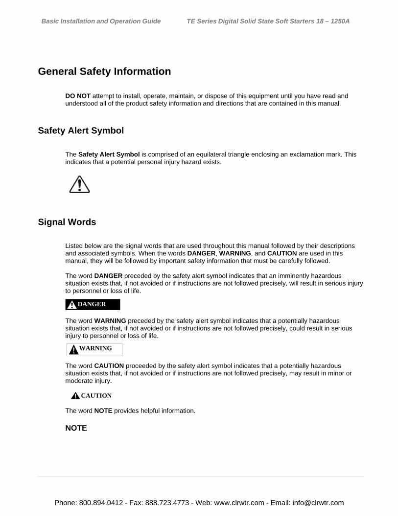
The Safety Alert Symbol is comprised of an equilateral triangle enclosing an exclamation mark. This indicates that a potential personal injury hazard exists.
Signal Words
Listed below are the signal words that are used throughout this manual followed by their descriptions and associated symbols. When the words DANGER, WARNING, and CAUTION are used in this manual, they will be followed by important safety information that must be carefully followed. The word DANGER preceded by the safety alert symbol indicates that an imminently hazardous situation exists that, if not avoided or if instructions are not followed precisely, will result in serious injury to personnel or loss of life.
The word WARNING preceded by the safety alert symbol indicates that a potentially hazardous situation exists that, if not avoided or if instructions are not followed precisely, could result in serious injury to personnel or loss of life.
The word CAUTION proceeded by the safety alert symbol indicates that a potentially hazardous situation exists that, if not avoided or if instructions are not followed precisely, may result in minor or moderate injury.
The word NOTE provides helpful information. NOTE
DANGER
WARNING
CAUTION
Phone: 800.894.0412 - Fax: 888.723.4773 - Web: www.clrwtr.com - Email: [email protected]
Basic Installation and Operation Guide TE Series Digital Solid State Soft Starters 18 – 1250A
Equipment Warning Labels
DO NOT attempt to install, operate, perform maintenance, or dispose of this equipment, until you have read and understood all of the product labels, and user directions, that are contained in this manual. Warning labels that are attached to the equipment will include the exclamation mark within a triangle. DO NOT remove or cover any of these labels. If the labels are damaged or if additional labels are required, contact the Toshiba Customer Support Center. Labels attached to the equipment are there to provide useful information or to indicate an imminently hazardous situation that may result in serious injury, severe property and equipment damage, or loss of life if safe procedures or methods are not followed as outlined in this manual.
Qualified Personnel
Installation, operation, and maintenance shall be performed by Qualified Personnel ONLY. A Qualified Person is one that has the skills and knowledge relating to the construction, installation, operation, and maintenance of the electrical equipment and has received safety training on the hazards involved (Refer to the latest edition of NFPA 70E for additional safety requirements). Qualified Personnel shall: • Have carefully read the entire manual. • Be familiar with the construction and function of the starter, the equipment being driven, and the hazards involved. • Be able to recognize and properly address hazards associated with the application of motor-driven equipment. • Be trained and authorized to safely energize, de-energize, ground, lock-out/tag-out circuits and equipment, and clear faults in accordance with established safety practices. • Be trained in the proper care and use of protective equipment such as safety shoes, rubber gloves, hard hats, safety glasses, face shields, flash clothing, etc., in accordance with established safety practices. For further information on workplace safety, visit www.osha.gov.
Phone: 800.894.0412 - Fax: 888.723.4773 - Web: www.clrwtr.com - Email: [email protected]
Basic Installation and Operation Guide TE Series Digital Solid State Soft Starters 18 – 1250A
Equipment Inspection • Upon receipt of the equipment, inspect the packaging and equipment for shipping damage. • Carefully unpack the equipment and check for parts that may have been damaged during shipping, missing parts, or concealed damage. If any discrepancies are discovered, it should be noted with the carrier prior to accepting the shipment, if possible. File a claim with the carrier if necessary and immediately notify your Toshiba Customer Support Center. • DO NOT install the starter if it is damaged or if it is missing any component(s). • Ensure that the rated capacity and the model number specified on the nameplate conform to the order specifications. • Modification of this equipment is dangerous and is to be performed by factory trained personnel ONLY. When modifications are required contact your Toshiba Customer Support Center. • Inspections may be required after moving the equipment. • Contact your Toshiba Customer Support Center to report discrepancies or for assistance if required.
Handling and Storage • Use proper lifting techniques when moving the breaker; including properly sizing up the load, getting assistance, and using a forklift if required. • Store in a well-ventilated location and preferably in the original packaging if the equipment will not be used upon receipt. • Store in a cool, clean, and dry location. Avoid storage locations with extreme temperatures, rapid temperature changes, high humidity, moisture, dust, corrosive gases, or metal particles. • The storage temperature range of the breaker is 23° to 104° F (-5° to 40° C). • DO NOT store the unit in places that are exposed to outside weather conditions (e.g., wind, rain, snow). • Store in an upright position.
Disposal Never dispose of electrical components via incineration. Contact your state environmental agency for details on disposal of electrical components and packaging in your area.
Phone: 800.894.0412 - Fax: 888.723.4773 - Web: www.clrwtr.com - Email: [email protected]
Basic Installation and Operation Guide TE Series Digital Solid State Soft Starters 18 – 1250A
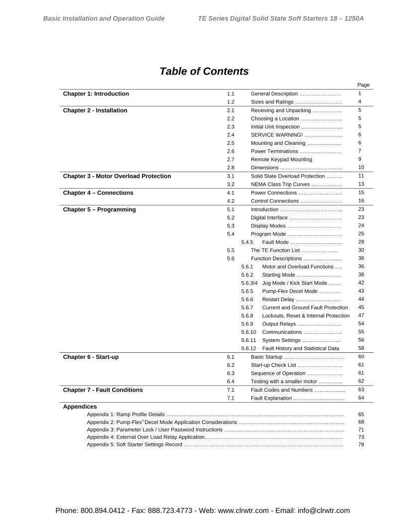
Table of Contents Page
Chapter 1: Introduction 1.1 General Description …………………… 1
1.2 Sizes and Ratings ……………………… 4
Chapter 2 - Installation 2.1 Receiving and Unpacking …………….. 5
2.2 Choosing a Location …………………... 5
2.3 Initial Unit Inspection …………………... 5
2.4 SERVICE WARNING! …………………. 6
2.5 Mounting and Cleaning ……………….. 6
2.6 Power Terminations …………………… 7
2.7 Remote Keypad Mounting 9
2.8 Dimensions ……………………………... 10
Chapter 3 - Motor Overload Protection 3.1 Solid State Overload Protection ……… 11
3.2 NEMA Class Trip Curves ……………... 13
Chapter 4 – Connections 4.1 Power Connections ……………………. 15
4.2 Control Connections …………………… 16
Chapter 5 – Programming 5.1 Introduction ……………………………... 23
5.2 Digital Interface ………………………… 23
5.3 Display Modes …………………………. 24
5.4 Program Mode …………………………. 25
5.4.5 Fault Mode ………………………… 28
5.5 The TE Function List ………………... 30
5.6 Function Descriptions …………………. 36
5.6.1 Motor and Overload Functions …. 36
5.6.2 Starting Mode ……………………. 38
5.6.3/4 Jog Mode / Kick Start Mode ……. 42
5.6.5 Pump-Flex Decel Mode ………… 43
5.6.6 Restart Delay ……………………. 44
5.6.7 Current and Ground Fault Protection 45
5.6.8 Lockouts, Reset & Internal Protection 47
5.6.9 Output Relays ……………………. 54
5.6.10 Communications …………………. 55
5.6.11 System Settings …………………. 56
5.6.12 Fault History and Statistical Data 58
Chapter 6 - Start-up 6.1 Basic Startup ……………………………. 60
6.2 Start-up Check List …………………….. 61
6.3 Sequence of Operation ………………... 61
6.4 Testing with a smaller motor ………….. 62
Chapter 7 - Fault Conditions 7.1 Fault Codes and Numbers ……………... 63
7.1 Fault Explanation ……………................. 64
Appendices
Appendix 1: Ramp Profile Details ……………………………………………………………………………………….. 65
Appendix 2: Pump-FlexDecel Mode Application Considerations …………………………………………………… 68
Appendix 3: Parameter Lock / User Password Instructions ………………………………………………………….. 71
Appendix 4: External Over Load Relay Application……………………………………………................................. 73
Appendix 5: Soft Starter Settings Record ………………………….…………….…………………………………….. 78
Phone: 800.894.0412 - Fax: 888.723.4773 - Web: www.clrwtr.com - Email: [email protected]
Basic Installation and Operation Guide TE Series Digital Solid State Soft Starters 18 – 1250A
1 | P a g e
Chapter 1 - Introduction 1.1 General Description
The TE Series is a digitally programmable solid-state reduced voltage soft starter. Its six SCR design features a voltage/current ramp with an anti-oscillation circuit for smooth load acceleration. The SCRs are sized to withstand starting currents of 500% for 60 seconds. The TE Series features smooth, step-less ramp control, which reduces motor inrush current and excessive wear on the mechanical drive train components. The TE Series includes a programmable keypad for setting operating parameters for the ideal starting cycle and protection features, plus easy to understand diagnostic LEDs. Starting torque, ramp time, current limit, dual ramp, and Decel control are standard features on the TE Series. By simply adjusting the unit’s starting torque, ramp time and current limit functions, the starting electrical characteristics of the motor can be matched to the mechanical characteristics of the drive train for controlled acceleration of the load. The TE Series includes solid-state electronic overload protection in addition to numerous other protective features. It requires 120VAC (220VAC optional) control power and uses dry contact inputs for Start / Stop control. Programmable auxiliary contacts and provisions for interlocking are also included.
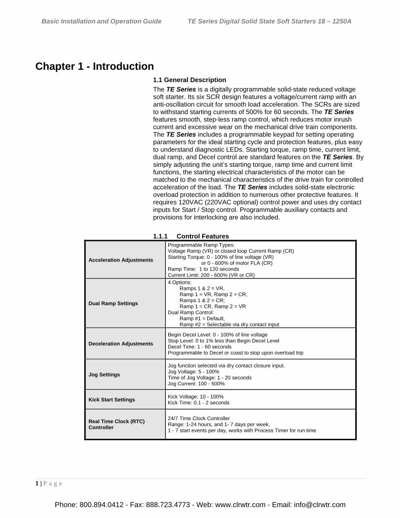
1.1.1 Control Features
Acceleration Adjustments
Programmable Ramp Types: Voltage Ramp (VR) or closed loop Current Ramp (CR) Starting Torque: 0 - 100% of line voltage (VR) or 0 - 600% of motor FLA (CR) Ramp Time: 1 to 120 seconds Current Limit: 200 - 600% (VR or CR)
Dual Ramp Settings
4 Options: Ramps 1 & 2 = VR, Ramp 1 = VR, Ramp 2 = CR, Ramps 1 & 2 = CR; Ramp 1 = CR, Ramp 2 = VR Dual Ramp Control: Ramp #1 = Default, Ramp #2 = Selectable via dry contact input
Deceleration Adjustments
Begin Decel Level: 0 - 100% of line voltage Stop Level: 0 to 1% less than Begin Decel Level Decel Time: 1 - 60 seconds Programmable to Decel or coast to stop upon overload trip
Jog Settings
Jog function selected via dry contact closure input. Jog Voltage: 5 - 100% Time of Jog Voltage: 1 - 20 seconds Jog Current: 100 - 500%
Kick Start Settings Kick Voltage: 10 - 100% Kick Time: 0.1 - 2 seconds
Real Time Clock (RTC) Controller
24/7 Time Clock Controller Range: 1-24 hours, and 1- 7 days per week, 1 - 7 start events per day, works with Process Timer for run time
Phone: 800.894.0412 - Fax: 888.723.4773 - Web: www.clrwtr.com - Email: [email protected]
Basic Installation and Operation Guide TE Series Digital Solid State Soft Starters 18 – 1250A
2 | P a g e
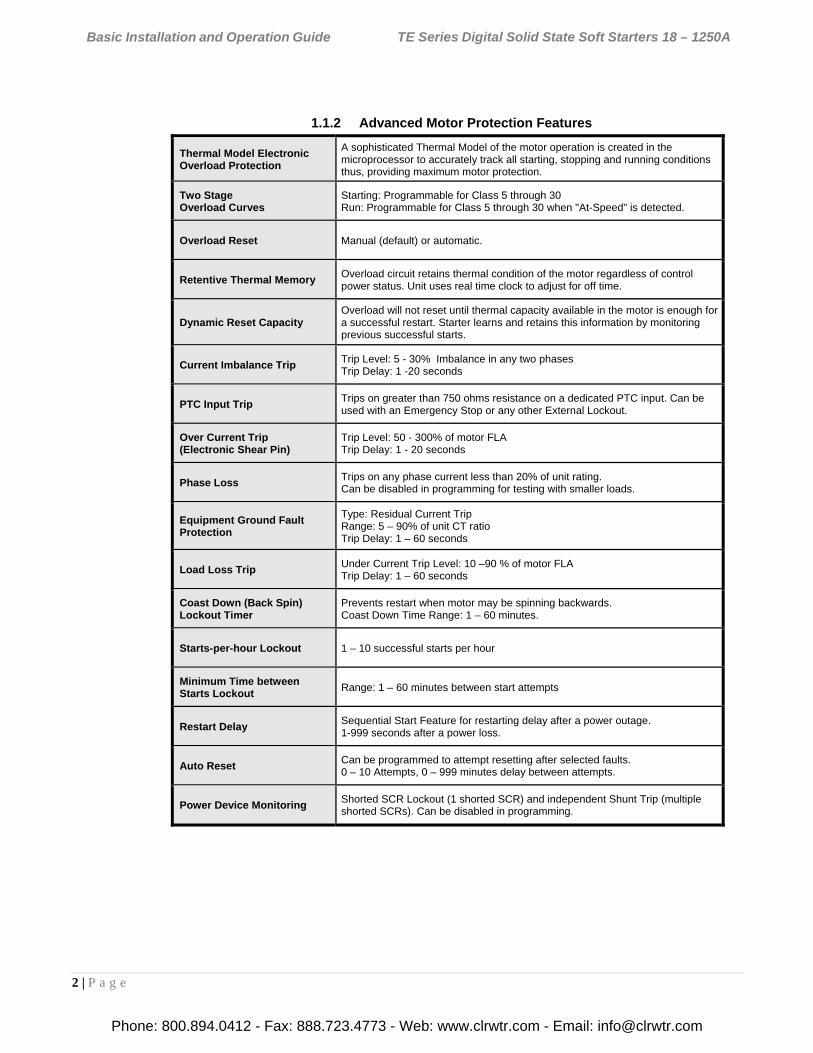
1.1.2 Advanced Motor Protection Features
Thermal Model Electronic Overload Protection
A sophisticated Thermal Model of the motor operation is created in the microprocessor to accurately track all starting, stopping and running conditions thus, providing maximum motor protection.
Two Stage Overload Curves
Starting: Programmable for Class 5 through 30 Run: Programmable for Class 5 through 30 when "At-Speed" is detected.
Overload Reset Manual (default) or automatic.
Retentive Thermal Memory Overload circuit retains thermal condition of the motor regardless of control power status. Unit uses real time clock to adjust for off time.
Dynamic Reset Capacity Overload will not reset until thermal capacity available in the motor is enough for a successful restart. Starter learns and retains this information by monitoring previous successful starts.
Current Imbalance Trip Trip Level: 5 - 30% Imbalance in any two phases Trip Delay: 1 -20 seconds
PTC Input Trip Trips on greater than 750 ohms resistance on a dedicated PTC input. Can be used with an Emergency Stop or any other External Lockout.
Over Current Trip (Electronic Shear Pin)
Trip Level: 50 - 300% of motor FLA Trip Delay: 1 - 20 seconds
Phase Loss Trips on any phase current less than 20% of unit rating. Can be disabled in programming for testing with smaller loads.
Equipment Ground Fault Protection
Type: Residual Current Trip Range: 5 – 90% of unit CT ratio Trip Delay: 1 – 60 seconds
Load Loss Trip Under Current Trip Level: 10 –90 % of motor FLA Trip Delay: 1 – 60 seconds
Coast Down (Back Spin) Lockout Timer
Prevents restart when motor may be spinning backwards. Coast Down Time Range: 1 – 60 minutes.
Starts-per-hour Lockout 1 – 10 successful starts per hour
Minimum Time between Starts Lockout
Range: 1 – 60 minutes between start attempts
Restart Delay Sequential Start Feature for restarting delay after a power outage. 1-999 seconds after a power loss.
Auto Reset Can be programmed to attempt resetting after selected faults. 0 – 10 Attempts, 0 – 999 minutes delay between attempts.
Power Device Monitoring Shorted SCR Lockout (1 shorted SCR) and independent Shunt Trip (multiple shorted SCRs). Can be disabled in programming.
Phone: 800.894.0412 - Fax: 888.723.4773 - Web: www.clrwtr.com - Email: [email protected]
Basic Installation and Operation Guide TE Series Digital Solid State Soft Starters 18 – 1250A
3 | P a g e
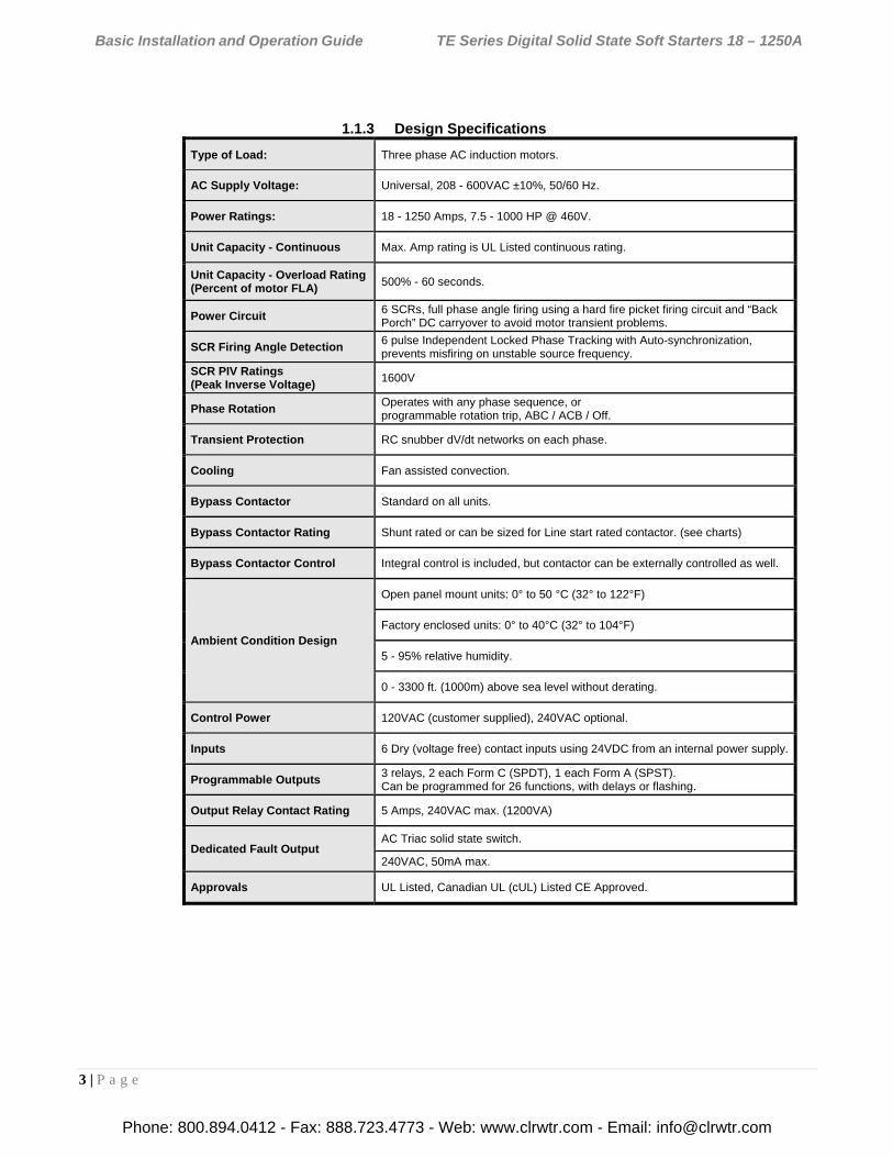
1.1.3 Design Specifications
Type of Load: Three phase AC induction motors.
AC Supply Voltage: Universal, 208 - 600VAC ±10%, 50/60 Hz.
Power Ratings: 18 - 1250 Amps, 7.5 - 1000 HP @ 460V.
Unit Capacity - Continuous Max. Amp rating is UL Listed continuous rating.
Unit Capacity - Overload Rating (Percent of motor FLA)
500% - 60 seconds.
Power Circuit 6 SCRs, full phase angle firing using a hard fire picket firing circuit and “Back Porch” DC carryover to avoid motor transient problems.
SCR Firing Angle Detection 6 pulse Independent Locked Phase Tracking with Auto-synchronization, prevents misfiring on unstable source frequency.
SCR PIV Ratings (Peak Inverse Voltage)
1600V
Phase Rotation Operates with any phase sequence, or programmable rotation trip, ABC / ACB / Off.
Transient Protection RC snubber dV/dt networks on each phase.
Cooling Fan assisted convection.
Bypass Contactor Standard on all units.
Bypass Contactor Rating Shunt rated or can be sized for Line start rated contactor. (see charts)
Bypass Contactor Control Integral control is included, but contactor can be externally controlled as well.
Ambient Condition Design
Open panel mount units: 0° to 50 °C (32° to 122°F)
Factory enclosed units: 0° to 40°C (32° to 104°F)
5 - 95% relative humidity.
0 - 3300 ft. (1000m) above sea level without derating.
Control Power 120VAC (customer supplied), 240VAC optional.
Inputs 6 Dry (voltage free) contact inputs using 24VDC from an internal power supply.
Programmable Outputs 3 relays, 2 each Form C (SPDT), 1 each Form A (SPST). Can be programmed for 26 functions, with delays or flashing.
Output Relay Contact Rating 5 Amps, 240VAC max. (1200VA)
Dedicated Fault Output AC Triac solid state switch.
240VAC, 50mA max.
Approvals UL Listed, Canadian UL (cUL) Listed CE Approved.
Phone: 800.894.0412 - Fax: 888.723.4773 - Web: www.clrwtr.com - Email: [email protected]
Basic Installation and Operation Guide TE Series Digital Solid State Soft Starters 18 – 1250A
4 | P a g e
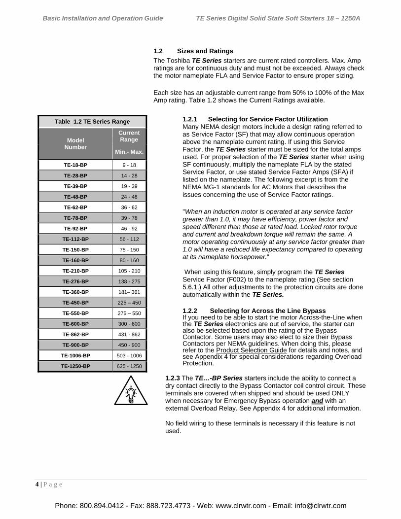
1.2 Sizes and Ratings
The Toshiba TE Series starters are current rated controllers. Max. Amp ratings are for continuous duty and must not be exceeded. Always check the motor nameplate FLA and Service Factor to ensure proper sizing.
Each size has an adjustable current range from 50% to 100% of the Max Amp rating. Table 1.2 shows the Current Ratings available.
1.2.1 Selecting for Service Factor Utilization Many NEMA design motors include a design rating referred to as Service Factor (SF) that may allow continuous operation above the nameplate current rating. If using this Service Factor, the TE Series starter must be sized for the total amps used. For proper selection of the TE Series starter when using SF continuously, multiply the nameplate FLA by the stated Service Factor, or use stated Service Factor Amps (SFA) if listed on the nameplate. The following excerpt is from the NEMA MG-1 standards for AC Motors that describes the issues concerning the use of Service Factor ratings.
"When an induction motor is operated at any service factor greater than 1.0, it may have efficiency, power factor and speed different than those at rated load. Locked rotor torque and current and breakdown torque will remain the same. A motor operating continuously at any service factor greater than 1.0 will have a reduced life expectancy compared to operating at its nameplate horsepower." When using this feature, simply program the TE Series Service Factor (F002) to the nameplate rating.(See section 5.6.1.) All other adjustments to the protection circuits are done automatically within the TE Series.
1.2.2 Selecting for Across the Line Bypass If you need to be able to start the motor Across-the-Line when the TE Series electronics are out of service, the starter can also be selected based upon the rating of the Bypass Contactor. Some users may also elect to size their Bypass Contactors per NEMA guidelines. When doing this, please refer to the Product Selection Guide for details and notes, and see Appendix 4 for special considerations regarding Overload Protection.
1.2.3 The TE…-BP Series starters include the ability to connect a dry contact directly to the Bypass Contactor coil control circuit. These terminals are covered when shipped and should be used ONLY when necessary for Emergency Bypass operation and with an external Overload Relay. See Appendix 4 for additional information. No field wiring to these terminals is necessary if this feature is not used.
Table 1.2 TE Series Range
Model Number
Current Range
Min.- Max.
TE-18-BP 9 - 18
TE-28-BP 14 - 28
TE-39-BP 19 - 39
TE-48-BP 24 - 48
TE-62-BP 36 - 62
TE-78-BP 39 - 78
TE-92-BP 46 - 92
TE-112-BP 56 - 112
TE-150-BP 75 - 150
TE-160-BP 80 - 160
TE-210-BP 105 - 210
TE-276-BP 138 - 275
TE-360-BP 181– 361
TE-450-BP 225 – 450
TE-550-BP 275 – 550
TE-600-BP 300 - 600
TE-862-BP 431 - 862
TE-900-BP 450 - 900
TE-1006-BP 503 - 1006
TE-1250-BP 625 - 1250
Phone: 800.894.0412 - Fax: 888.723.4773 - Web: www.clrwtr.com - Email: [email protected]
Basic Installation and Operation Guide TE Series Digital Solid State Soft Starters 18 – 1250A
5 | P a g e
Chapter 2 - Installation
2.1 Receiving and Unpacking
Upon receipt of the product, you should immediately do the following:
Carefully unpack the unit from the shipping carton and inspect it for shipping damage. If damaged, notify the freight carrier and file a claim within 15 days of receipt.
Verify that the model number on the unit matches your purchase order.
Confirm that the ratings nameplate on the unit matches or is greater than the motor’s HP and current rating with which it is to be used.
2.2 Choosing a Location
Proper location of the TE Series is necessary to achieve specified performance and normal operational lifetime. The TE Series should always be installed in an area where the following conditions exist:
Ambient operating temperature: Panel (open chassis) unit: 0 to 50°C (32 to 122°F) Enclosed unit: 0 to 40°C (32 to 104°F)
Protected from rain, moisture and direct sun.
Humidity: 5 to 95% non-condensing
Free from metallic particles, conductive dust and corrosive gas.
Free from excessive vibration. (below 0.5G)
Open panel units must be mounted in the appropriate type of enclosure. Enclosure size and type must be suitable to dissipate heat generated by the soft starter and any other components mounted inside with it.
Throughout all sizes, maximum heat dissipation of the TE…-BP Series electronics, contactor coils and fans is less than 50W.
Care should always be taken to maximize the available space inside of the enclosure. See section 2.5.1 or contact factory for assistance in sizing enclosures.
2.3 Initial Unit Inspection
Make a complete visual check of the unit for damage that may have occurred during shipping and handling. Do not attempt to continue installation or start up the unit if it is damaged.
Check for loose mechanical assemblies or broken wires which may have occurred during transportation or handling. Loose electrical connections will increase resistance and cause the unit to function improperly.
Prior to beginning the installation, verify that the motor and TE Series unit are rated for the proper amperage and voltage.
Phone: 800.894.0412 - Fax: 888.723.4773 - Web: www.clrwtr.com - Email: [email protected]
Basic Installation and Operation Guide TE Series Digital Solid State Soft Starters 18 – 1250A
6 | P a g e
2.4 SERVICE WARNING!
Do not service equipment with voltage applied! The unit can be the source of fatal electrical shocks! To avoid shock hazard, disconnect main power and control power before working on the unit. Warning labels must be attached to terminals, enclosure and control panel to meet local codes. Use Lock Out tags such as the one shown when servicing equipment.
2.5 Mounting and Cleaning
When drilling or punching holes in the enclosure, cover the electrical assembly to prevent metal filings from becoming lodged in areas which can cause clearance reduction or actual electrical shorts. After work is complete, thoroughly clean, vacuum the area, and re-inspect the unit for foreign material.
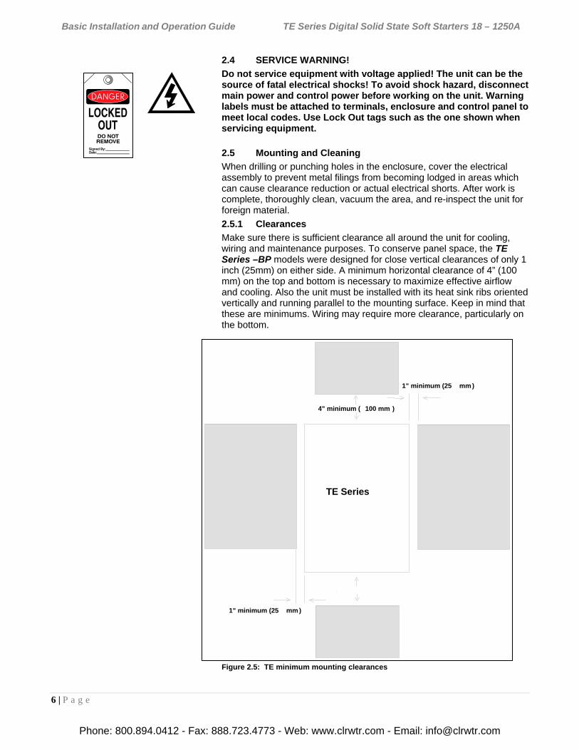
2.5.1 Clearances
Make sure there is sufficient clearance all around the unit for cooling, wiring and maintenance purposes. To conserve panel space, the TE Series –BP models were designed for close vertical clearances of only 1 inch (25mm) on either side. A minimum horizontal clearance of 4” (100 mm) on the top and bottom is necessary to maximize effective airflow and cooling. Also the unit must be installed with its heat sink ribs oriented vertically and running parallel to the mounting surface. Keep in mind that these are minimums. Wiring may require more clearance, particularly on the bottom.
Figure 2.5: TE minimum mounting clearances
Starter
1" minimum (25 mm )
1" minimum (25 mm )
4" minimum ( 100 mm )
TE Series
4" minimum ( 100 mm )
Phone: 800.894.0412 - Fax: 888.723.4773 - Web: www.clrwtr.com - Email: [email protected]
Basic Installation and Operation Guide TE Series Digital Solid State Soft Starters 18 – 1250A
7 | P a g e
WARNING!
Remove all sources of power before cleaning the unit.
In dirty or contaminated atmospheres, the unit should be cleaned on a regular basis to ensure proper cooling. Do not use any chemicals to clean the unit. To remove surface dust use clean, dry compressed air only, 80 to 100 psi. A three-inch, high quality, dry paintbrush is helpful to loosen up the dust prior to using compressed air on the unit. Do not use wire brushes or other conductive cleaning materials
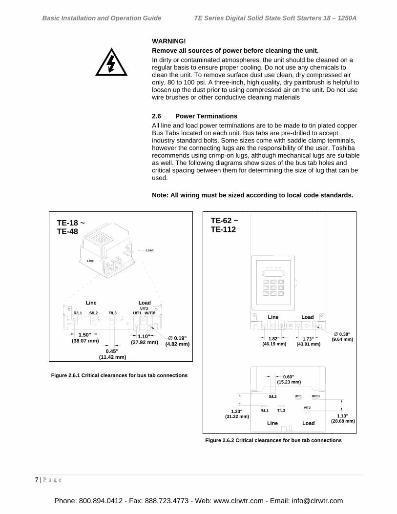
2.6 Power Terminations
All line and load power terminations are to be made to tin plated copper Bus Tabs located on each unit. Bus tabs are pre-drilled to accept industry standard bolts. Some sizes come with saddle clamp terminals, however the connecting lugs are the responsibility of the user. Toshiba recommends using crimp-on lugs, although mechanical lugs are suitable as well. The following diagrams show sizes of the bus tab holes and critical spacing between them for determining the size of lug that can be used.
Note: All wiring must be sized according to local code standards.
Figure 2.6.1 Critical clearances for bus tab connections
Figure 2.6.2 Critical clearances for bus tab connections
Line
Load
1.50"(38.07 mm)
0.45"(11.42 mm)
1.10"(27.92 mm)
0.19"(4.82 mm)
Line Load
TE-18 ~ TE-48
R/ L1 S/L2 T /L3V/ T2
U/ T1 W / T3/
TE-62 ~ TE-112
1.73" (43.91 mm)
0.38"(9.64 mm)1.82"
(46.19 mm)
S/L2
R/L1 T /L3
Line Load
U/ T1 W/ T3
V/T2
0.60"(15.23 mm)
1.13"(28.68 mm)
Line Load
1.23"(31.22 mm)
Phone: 800.894.0412 - Fax: 888.723.4773 - Web: www.clrwtr.com - Email: [email protected]
Basic Installation and Operation Guide TE Series Digital Solid State Soft Starters 18 – 1250A
8 | P a g e
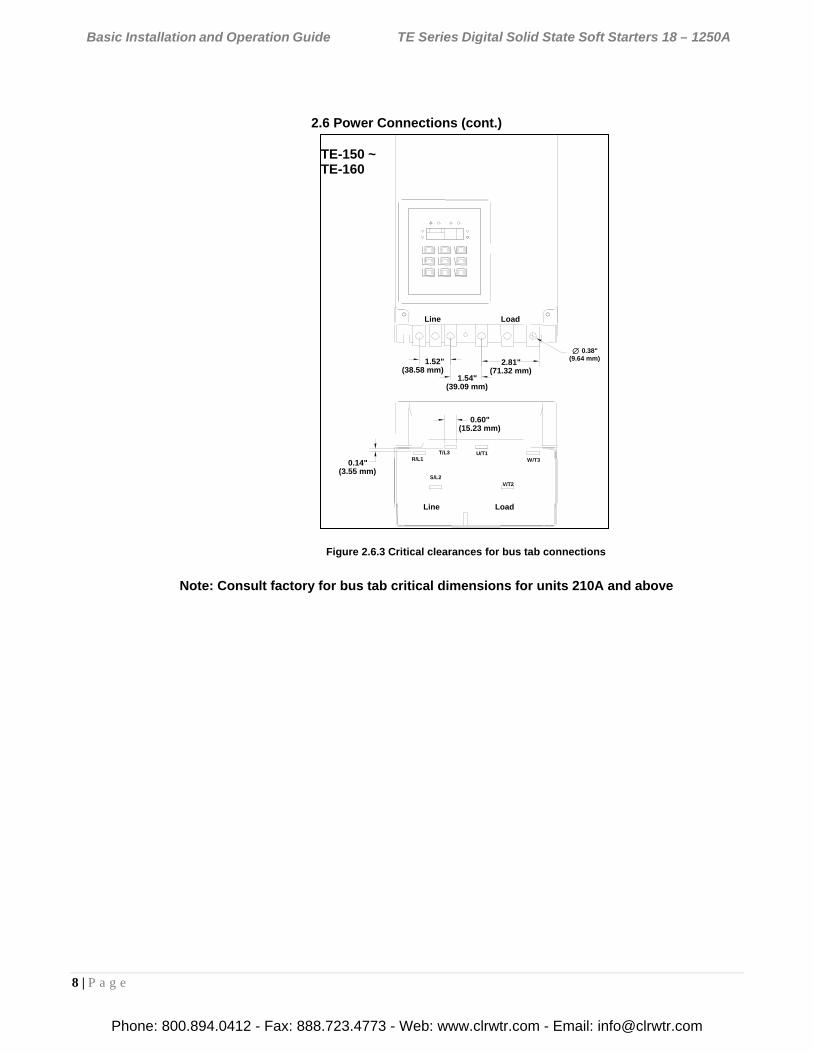
2.6 Power Connections (cont.)
Note: Consult factory for bus tab critical dimensions for units 210A and above
Figure 2.6.3 Critical clearances for bus tab connections
TE-150 ~TE-160
2.81"(71.32 mm)
0.38"(9.64 mm)
Line Load
1.54"(39.09 mm)
1.52"(38.58 mm)
T/L3R/L1
S/L2
Line Load
U/T1W/T3
V/T2
0.60"(15.23 mm)
0.14"(3.55 mm)
Phone: 800.894.0412 - Fax: 888.723.4773 - Web: www.clrwtr.com - Email: [email protected]
Basic Installation and Operation Guide TE Series Digital Solid State Soft Starters 18 – 1250A
9 | P a g e
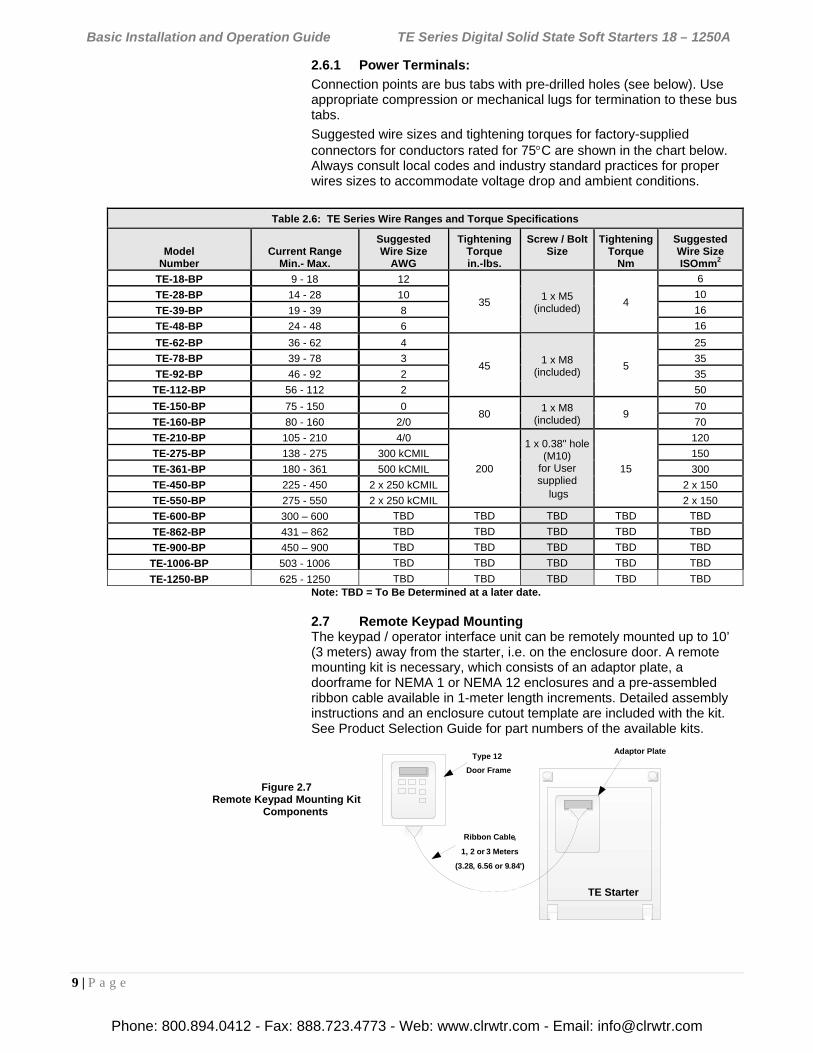
2.6.1 Power Terminals:
Connection points are bus tabs with pre-drilled holes (see below). Use appropriate compression or mechanical lugs for termination to these bus tabs.
Suggested wire sizes and tightening torques for factory-supplied connectors for conductors rated for 75C are shown in the chart below. Always consult local codes and industry standard practices for proper wires sizes to accommodate voltage drop and ambient conditions.
Table 2.6: TE Series Wire Ranges and Torque Specifications
Model Number
Current Range Min.- Max.
Suggested Wire Size
AWG
Tightening Torque in.-lbs.
Screw / Bolt Size
Tightening Torque
Nm
Suggested Wire Size ISOmm2
TE-18-BP 9 - 18 12
35 1 x M5
(included) 4
6
TE-28-BP 14 - 28 10 10
TE-39-BP 19 - 39 8 16
TE-48-BP 24 - 48 6 16
TE-62-BP 36 - 62 4
45 1 x M8
(included) 5
25
TE-78-BP 39 - 78 3 35
TE-92-BP 46 - 92 2 35
TE-112-BP 56 - 112 2 50
TE-150-BP 75 - 150 0 80
1 x M8 (included)
9 70
TE-160-BP 80 - 160 2/0 70
TE-210-BP 105 - 210 4/0
200
1 x 0.38" hole (M10)
for User supplied
lugs
15
120
TE-275-BP 138 - 275 300 kCMIL 150
TE-361-BP 180 - 361 500 kCMIL 300
TE-450-BP 225 - 450 2 x 250 kCMIL 2 x 150
TE-550-BP 275 - 550 2 x 250 kCMIL 2 x 150
TE-600-BP 300 – 600 TBD TBD TBD TBD TBD
TE-862-BP 431 – 862 TBD TBD TBD TBD TBD
TE-900-BP 450 – 900 TBD TBD TBD TBD TBD
TE-1006-BP 503 - 1006 TBD TBD TBD TBD TBD
TE-1250-BP 625 - 1250 TBD TBD TBD TBD TBD Note: TBD = To Be Determined at a later date.
2.7 Remote Keypad Mounting The keypad / operator interface unit can be remotely mounted up to 10’ (3 meters) away from the starter, i.e. on the enclosure door. A remote mounting kit is necessary, which consists of an adaptor plate, a doorframe for NEMA 1 or NEMA 12 enclosures and a pre-assembled ribbon cable available in 1-meter length increments. Detailed assembly instructions and an enclosure cutout template are included with the kit. See Product Selection Guide for part numbers of the available kits.
Figure 2.7 Remote Keypad Mounting Kit
Components
TE Starter
Adaptor PlateType 12
Door Frame
Ribbon Cable,
1, 2 or 3 Meters
(3.28, 6.56 or 9.84')
Phone: 800.894.0412 - Fax: 888.723.4773 - Web: www.clrwtr.com - Email: [email protected]
Basic Installation and Operation Guide TE Series Digital Solid State Soft Starters 18 – 1250A
10 | P a g e
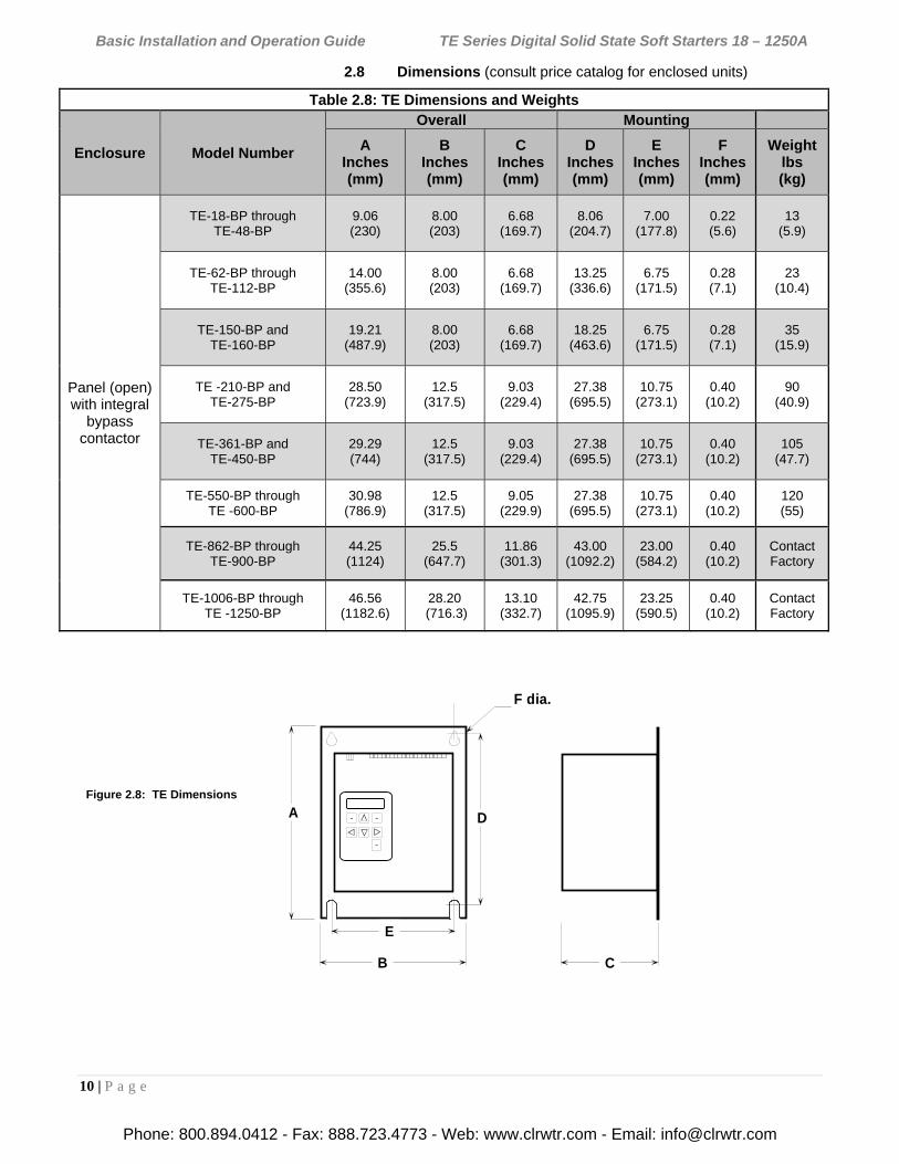
2.8 Dimensions (consult price catalog for enclosed units)
Figure 2.8: TE Dimensions
Table 2.8: TE Dimensions and Weights
Enclosure Model Number
Overall Mounting
A Inches (mm)
B Inches (mm)
C Inches (mm)
D Inches (mm)
E Inches (mm)
F Inches (mm)
Weight lbs (kg)
Panel (open) with integral
bypass contactor
TE-18-BP through TE-48-BP
9.06 (230)
8.00 (203)
6.68 (169.7)
8.06 (204.7)
7.00 (177.8)
0.22 (5.6)
13 (5.9)
TE-62-BP through TE-112-BP
14.00 (355.6)
8.00 (203)
6.68 (169.7)
13.25 (336.6)
6.75 (171.5)
0.28 (7.1)
23 (10.4)
TE-150-BP and TE-160-BP
19.21 (487.9)
8.00 (203)
6.68 (169.7)
18.25 (463.6)
6.75 (171.5)
0.28 (7.1)
35 (15.9)
TE -210-BP and TE-275-BP
28.50 (723.9)
12.5 (317.5)
9.03 (229.4)
27.38 (695.5)
10.75 (273.1)
0.40 (10.2)
90 (40.9)
TE-361-BP and TE-450-BP
29.29 (744)
12.5 (317.5)
9.03 (229.4)
27.38 (695.5)
10.75 (273.1)
0.40 (10.2)
105 (47.7)
TE-550-BP through TE -600-BP
30.98 (786.9)
12.5 (317.5)
9.05 (229.9)
27.38 (695.5)
10.75 (273.1)
0.40 (10.2)
120 (55)
TE-862-BP through TE-900-BP
44.25 (1124)
25.5 (647.7)
11.86 (301.3)
43.00 (1092.2)
23.00 (584.2)
0.40 (10.2)
Contact Factory
TE-1006-BP through TE -1250-BP
46.56 (1182.6)
28.20 (716.3)
13.10 (332.7)
42.75 (1095.9)
23.25 (590.5)
0.40 (10.2)
Contact Factory
F dia.
D
E
B
A
C
~ ~
~
Phone: 800.894.0412 - Fax: 888.723.4773 - Web: www.clrwtr.com - Email: [email protected]
Basic Installation and Operation Guide TE Series Digital Solid State Soft Starters 18 – 1250A
11 | P a g e
Chapter 3 - Motor Overload Protection
3.1 Solid State Overload Protection
The TE Series Starter provides true U.L. listed I2t Thermal Overload Protection as a built-in function of the main digital processor for maximum motor protection. It simulates the tripping action of a bi-metallic overload relay, with the accuracy and repeatability of a digital control system. It is adjustable over a wide range and can be easily programmed for different trip curves.
3.1.1 Thermal Memory
The TE Series microprocessor uses a sophisticated “Thermal Register” in the digital memory to keep track of motor heating and cooling over time regardless of the starter’s power status. By using non-volatile memory, the TE Series does not “forget” that the motor has been running even if power to the starter is turned off and turned back on. Continuous overload protection is provided based on the true thermal condition of the motor.
3.1.2 Thermal Capacity
The Thermal Register is displayed as a percentage. This percentage is the motor’s remaining thermal capacity. The percentage value begins at 100; showing that the motor is cool (has 100% of its capacity available). As the motor heats up or moves toward an overload condition, the percentage begins to drop. The Thermal Capacity is derived from the programmed motor nameplate Full Load Amps (FLA) in Function F001, the Service Factor rating in Function F002, and the Overload Trip Class in Functions F003 and F004. Setting these functions to the proper values provides maximum protection and eliminates nuisance tripping.
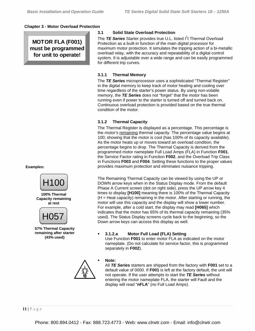
The Remaining Thermal Capacity can be viewed by using the UP or DOWN arrow keys when in the Status Display mode. From the default Phase A Current screen (dot on right side), press the UP arrow key 4 times to display [H100] meaning there is 100% of the Thermal Capacity (H = Heat capacity) remaining in the motor. After starting or running, the motor will use this capacity and the display will show a lower number. For example, after a cold start, the display may read [H065] which indicates that the motor has 65% of its thermal capacity remaining (35% used). The Status Display screens cycle back to the beginning, so the Down arrow keys can access this display as well.
3.1.2.a Motor Full Load (FLA) Setting Use Function F001 to enter motor FLA as indicated on the motor nameplate. (Do not calculate for service factor, this is programmed separately in F002).
Note: All TE Series starters are shipped from the factory with F001 set to a default value of 0000. If F001 is left at the factory default, the unit will not operate. If the user attempts to start the TE Series without entering the motor nameplate FLA, the starter will Fault and the display will read “nFLA” (no Full Load Amps).
MOTOR FLA (F001)must be programmed
for unit to operate!
H100
H057
100% Thermal Capacity remaining
at rest
57% Thermal Capacity remaining after starter
(43% used)
Examples:
Phone: 800.894.0412 - Fax: 888.723.4773 - Web: www.clrwtr.com - Email: [email protected]
Basic Installation and Operation Guide TE Series Digital Solid State Soft Starters 18 – 1250A
12 | P a g e
3.1.3 Disabling the Overload Protection The Overload Protection feature can be disabled if necessary. When using external devices such as Motor Protection Relays or when the TE Series is wired downstream from an existing starter, this feature can be disabled to prevent conflicts with external overload protection devices. When the TE Series is controlling multiple motors, the built-in Overload protection must be disabled and individual thermal overload relays must be installed on the motor leads going to each motor (see appendix 4 for additional details). To disable the Overload Protection function, use F005.
WARNING!
Do NOT disable Overload Protection unless another Thermal Overload Protection device exists in the circuit for all three phases. Running a motor without Overload Protection presents serious risk of motor damage or fire.
3.1.3.a Manual Reset The factory default setting is Manual Reset. This means that when the Overload Trip is activated, the starter cannot be restarted without pressing the Reset key. The Overload Trip will not reset until the motor cools down (see 3.1.3.d). The Manual Reset function is also “trip free”. Holding in the Reset key will not prevent the Overload Trip from activating and protecting the motor.
Note: When the Overload Trip activates, the Overload LED will be on solid. When the motor cools down, the LED will begin to flash, indicating that the Overload Trip can be reset.
3.1.3.b Automatic Reset If Automatic Reset is necessary, change from Manual Reset to Automatic Reset by using Function F005. (See Section 5 for details). In this mode, a 3-wire control circuit will be capable of restart when the TE Series has reset itself after the cool down period.
WARNING!
Two-wire control systems may restart without warning when Auto Reset of the overload protection is selected. Extreme caution should be exercised. To prevent automatic restarting with 2-wire control systems, use external interlocking to provide sufficient warning and safety to operators. A Warning Label similar to that shown below (and the one provided in the packet with this manual) must be located where visible (on the starter enclosure and/or the driven equipment) as required by local code.
WARNING: MOTOR CONNECTED TO THIS EQUIPMENTMAY START AUTOMATICALLY WITHOUT WARNING
Phone: 800.894.0412 - Fax: 888.723.4773 - Web: www.clrwtr.com - Email: [email protected]
Basic Installation and Operation Guide TE Series Digital Solid State Soft Starters 18 – 1250A
13 | P a g e
3.1.3.c Overload Protection During Bypass When an integral Bypass Contactor is used to shunt power around the SCRs in the TE Series (as in the TE…-BP version), overload protection is maintained as long as the TE Series is directly controlling the contactor. No additional Overload Relay is necessary for normal operation.
When the Bypass Contactor on a TE…-BP Series has been selected to be used for Across-the-Line restart (reference section 1.2.3), supplemental overload protection is necessary. For this application, refer to the External Overload Relay Applications supplement and wiring diagram in Appendix 4.
3.1.3.d Dynamic Reset Capacity The TE Series includes the ability to dynamically track the Thermal Capacity needed for a successful restart after an overload trip. It averages the Thermal Capacity consumed in the previous three successful starts, and calculates a Thermal Capacity to Start (viewed in Function F059). After tripping on Overload, the Thermal Register must have regained the amount recorded in F059 before a Reset will be allowed. If the display reads [Inh] when attempting to reset an overload trip, it is indicating that the starter is Inhibited from being reset. Refer to details of Function F071 for information on emergency override of lockouts such as this.
3.2 NEMA Class Trip Curves
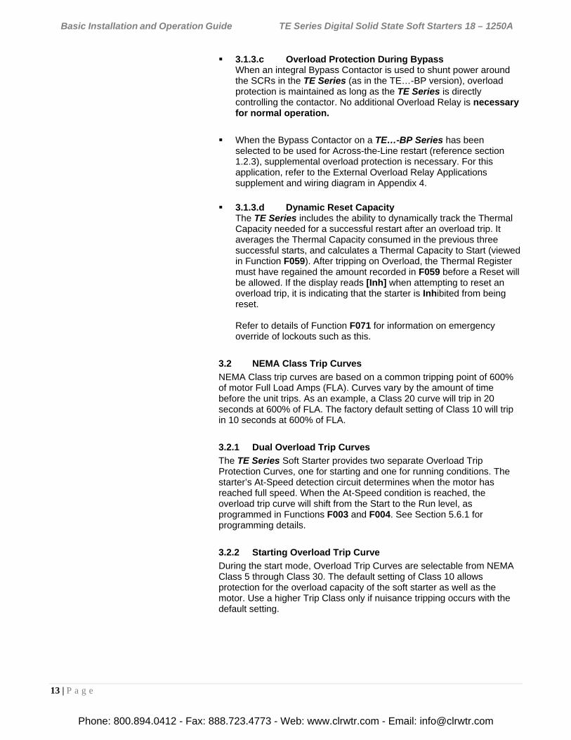
NEMA Class trip curves are based on a common tripping point of 600% of motor Full Load Amps (FLA). Curves vary by the amount of time before the unit trips. As an example, a Class 20 curve will trip in 20 seconds at 600% of FLA. The factory default setting of Class 10 will trip in 10 seconds at 600% of FLA.
3.2.1 Dual Overload Trip Curves
The TE Series Soft Starter provides two separate Overload Trip Protection Curves, one for starting and one for running conditions. The starter’s At-Speed detection circuit determines when the motor has reached full speed. When the At-Speed condition is reached, the overload trip curve will shift from the Start to the Run level, as programmed in Functions F003 and F004. See Section 5.6.1 for programming details.
3.2.2 Starting Overload Trip Curve
During the start mode, Overload Trip Curves are selectable from NEMA Class 5 through Class 30. The default setting of Class 10 allows protection for the overload capacity of the soft starter as well as the motor. Use a higher Trip Class only if nuisance tripping occurs with the default setting.
Phone: 800.894.0412 - Fax: 888.723.4773 - Web: www.clrwtr.com - Email: [email protected]
Basic Installation and Operation Guide TE Series Digital Solid State Soft Starters 18 – 1250A
14 | P a g e
3.2.3 Running Overload Curve
During the Run mode, Overload trip curves are selectable from NEMA Class 5, 10, 15, 20, 25, and 30. Program the appropriate curve according to the characteristics of your motor and load.
3.2.4 Overload Trip Curve Chart
Figure 3.2.4: TE Series Overload Trip Curves
Phone: 800.894.0412 - Fax: 888.723.4773 - Web: www.clrwtr.com - Email: [email protected]
Basic Installation and Operation Guide TE Series Digital Solid State Soft Starters 18 – 1250A
15 | P a g e
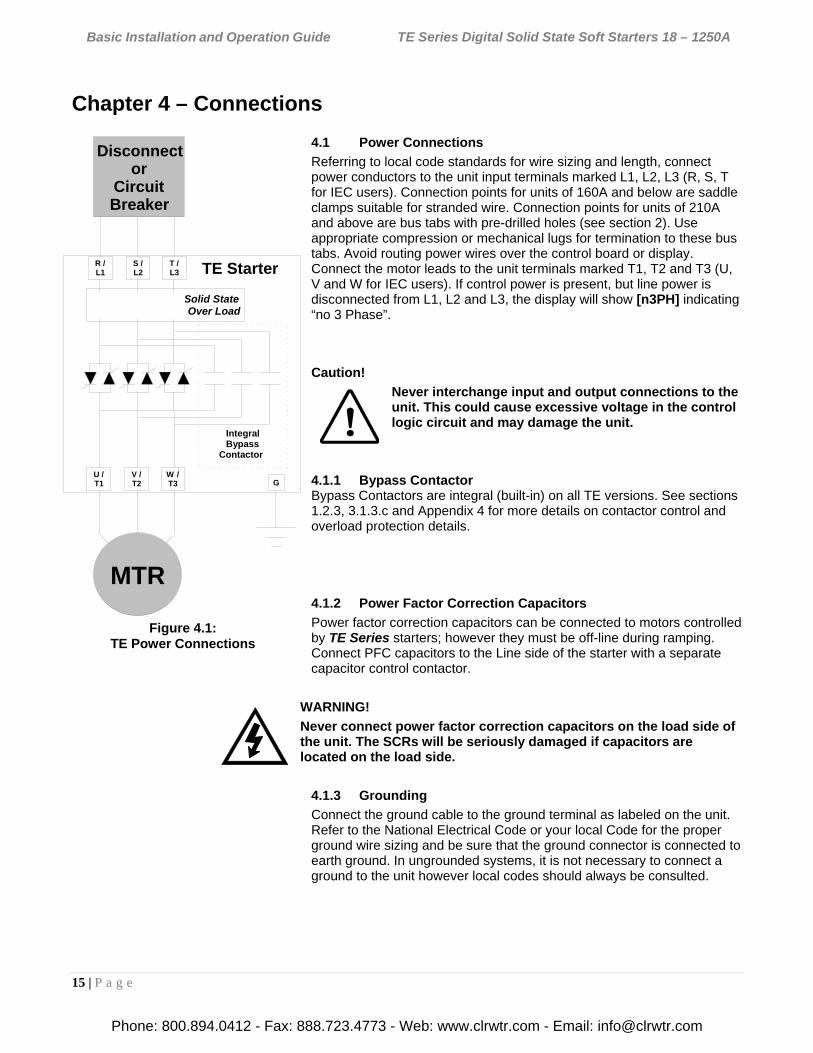
Figure 4.1: TE Power Connections
Chapter 4 – Connections
4.1 Power Connections
Referring to local code standards for wire sizing and length, connect power conductors to the unit input terminals marked L1, L2, L3 (R, S, T for IEC users). Connection points for units of 160A and below are saddle clamps suitable for stranded wire. Connection points for units of 210A and above are bus tabs with pre-drilled holes (see section 2). Use appropriate compression or mechanical lugs for termination to these bus tabs. Avoid routing power wires over the control board or display. Connect the motor leads to the unit terminals marked T1, T2 and T3 (U, V and W for IEC users). If control power is present, but line power is disconnected from L1, L2 and L3, the display will show [n3PH] indicating “no 3 Phase”.
Caution!
Never interchange input and output connections to the unit. This could cause excessive voltage in the control logic circuit and may damage the unit.
4.1.1 Bypass Contactor Bypass Contactors are integral (built-in) on all TE versions. See sections 1.2.3, 3.1.3.c and Appendix 4 for more details on contactor control and overload protection details.
4.1.2 Power Factor Correction Capacitors
Power factor correction capacitors can be connected to motors controlled by TE Series starters; however they must be off-line during ramping. Connect PFC capacitors to the Line side of the starter with a separate capacitor control contactor.
WARNING!
Never connect power factor correction capacitors on the load side of the unit. The SCRs will be seriously damaged if capacitors are located on the load side.
4.1.3 Grounding
Connect the ground cable to the ground terminal as labeled on the unit. Refer to the National Electrical Code or your local Code for the proper ground wire sizing and be sure that the ground connector is connected to earth ground. In ungrounded systems, it is not necessary to connect a ground to the unit however local codes should always be consulted.
Integral Bypass
Contactor
TE Starter .
Disconnector
Circuit Breaker
Solid State.Over Load .
MTR
G
R /L1
T /L3
S /L2
U /T1
W /T3
V / T2
Phone: 800.894.0412 - Fax: 888.723.4773 - Web: www.clrwtr.com - Email: [email protected]
Basic Installation and Operation Guide TE Series Digital Solid State Soft Starters 18 – 1250A
16 | P a g e
4.1.4 Testing
The TE Series can be tested with a load smaller than the motor it was originally selected to control, however additional steps must be taken to avoid tripping on Phase Current Loss. See section 5.6.8.a under “Phase Loss Protection” for additional details on performing this task.
Notes: The unit cannot be tested without a motor or other test load connected to the load side of the unit. It may be necessary to use a load bank to test the unit without a motor.
Line voltage will appear across the output terminals if there is no motor or load connected to the unit.
4.1.5 Lightning Protection
As with all electronic power controllers, protection from damage by lightning surges is recommended in areas where lightning is a significant problem. Stationary air gap lightning arrestors should be considered and utilized on the input power source. The best method of protection is to have an Isolation Contactor in front of the starter that is open when the soft starter is not in use. Enclosed versions can be ordered with an OPTIONAL secondary surge absorber.
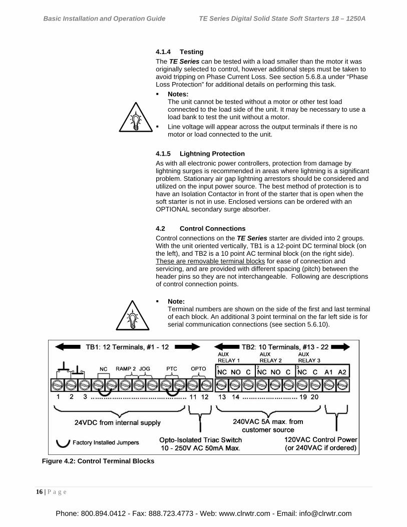
4.2 Control Connections
Control connections on the TE Series starter are divided into 2 groups. With the unit oriented vertically, TB1 is a 12-point DC terminal block (on the left), and TB2 is a 10 point AC terminal block (on the right side). These are removable terminal blocks for ease of connection and servicing, and are provided with different spacing (pitch) between the header pins so they are not interchangeable. Following are descriptions of control connection points.
Note: Terminal numbers are shown on the side of the first and last terminal of each block. An additional 3 point terminal on the far left side is for serial communication connections (see section 5.6.10).
Figure 4.2: Control Terminal Blocks
Phone: 800.894.0412 - Fax: 888.723.4773 - Web: www.clrwtr.com - Email: [email protected]
Basic Installation and Operation Guide TE Series Digital Solid State Soft Starters 18 – 1250A
17 | P a g e
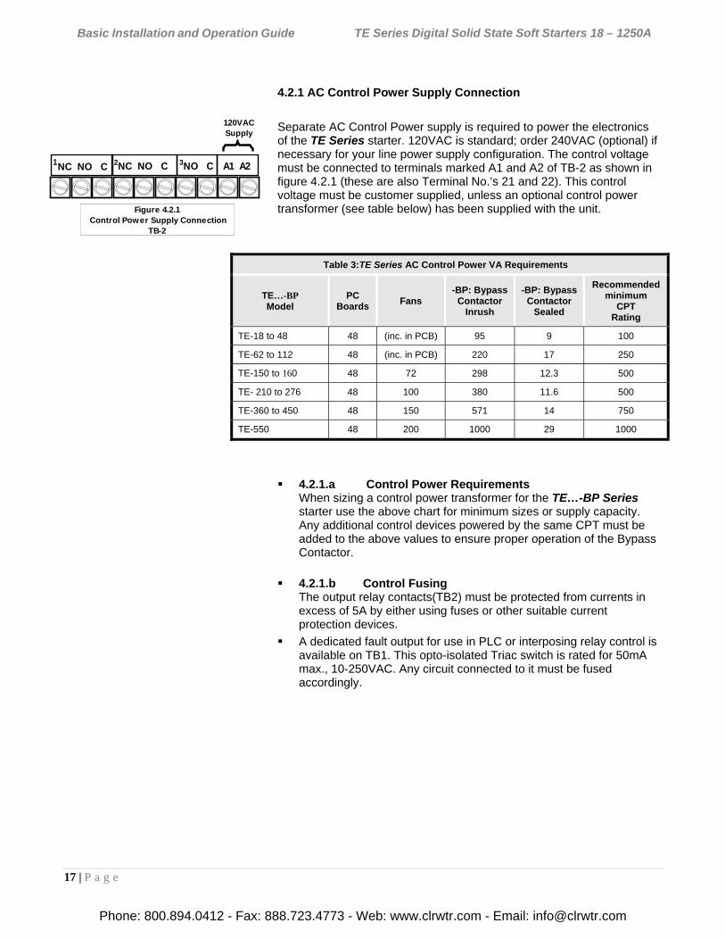
4.2.1 AC Control Power Supply Connection
Separate AC Control Power supply is required to power the electronics of the TE Series starter. 120VAC is standard; order 240VAC (optional) if necessary for your line power supply configuration. The control voltage must be connected to terminals marked A1 and A2 of TB-2 as shown in figure 4.2.1 (these are also Terminal No.’s 21 and 22). This control voltage must be customer supplied, unless an optional control power transformer (see table below) has been supplied with the unit.
4.2.1.a Control Power Requirements When sizing a control power transformer for the TE…-BP Series starter use the above chart for minimum sizes or supply capacity. Any additional control devices powered by the same CPT must be added to the above values to ensure proper operation of the Bypass Contactor.
4.2.1.b Control Fusing The output relay contacts(TB2) must be protected from currents in excess of 5A by either using fuses or other suitable current protection devices.
A dedicated fault output for use in PLC or interposing relay control is available on TB1. This opto-isolated Triac switch is rated for 50mA max., 10-250VAC. Any circuit connected to it must be fused accordingly.
Table 3:TE Series AC Control Power VA Requirements
TE…-BP Model
PC Boards
Fans -BP: Bypass
Contactor Inrush
-BP: Bypass Contactor
Sealed
Recommended minimum
CPT Rating
TE-18 to 48 48 (inc. in PCB) 95 9 100
TE-62 to 112 48 (inc. in PCB) 220 17 250
TE-150 to 160 48 72 298 12.3 500
TE- 210 to 276 48 100 380 11.6 500
TE-360 to 450 48 150 571 14 750
TE-550 48 200 1000 29 1000
120VACSupply
Figure 4.2.1 Control Power Supply Connection
TB-2
1NC NO. C 1A1 A22NC NO. C 3NO. C
Phone: 800.894.0412 - Fax: 888.723.4773 - Web: www.clrwtr.com - Email: [email protected]
Basic Installation and Operation Guide TE Series Digital Solid State Soft Starters 18 – 1250A
18 | P a g e
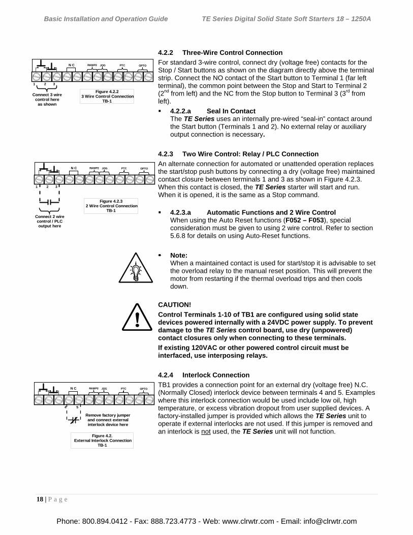
4.2.2 Three-Wire Control Connection
For standard 3-wire control, connect dry (voltage free) contacts for the Stop / Start buttons as shown on the diagram directly above the terminal strip. Connect the NO contact of the Start button to Terminal 1 (far left terminal), the common point between the Stop and Start to Terminal 2 (2nd from left) and the NC from the Stop button to Terminal 3 (3rd from left).
4.2.2.a Seal In Contact The TE Series uses an internally pre-wired “seal-in” contact around the Start button (Terminals 1 and 2). No external relay or auxiliary output connection is necessary.
4.2.3 Two Wire Control: Relay / PLC Connection
An alternate connection for automated or unattended operation replaces the start/stop push buttons by connecting a dry (voltage free) maintained contact closure between terminals 1 and 3 as shown in Figure 4.2.3. When this contact is closed, the TE Series starter will start and run. When it is opened, it is the same as a Stop command.
4.2.3.a Automatic Functions and 2 Wire Control When using the Auto Reset functions (F052 – F053), special consideration must be given to using 2 wire control. Refer to section 5.6.8 for details on using Auto-Reset functions.
Note: When a maintained contact is used for start/stop it is advisable to set the overload relay to the manual reset position. This will prevent the motor from restarting if the thermal overload trips and then cools down.
CAUTION!
Control Terminals 1-10 of TB1 are configured using solid state devices powered internally with a 24VDC power supply. To prevent damage to the TE Series control board, use dry (unpowered) contact closures only when connecting to these terminals.
If existing 120VAC or other powered control circuit must be interfaced, use interposing relays.
4.2.4 Interlock Connection
TB1 provides a connection point for an external dry (voltage free) N.C. (Normally Closed) interlock device between terminals 4 and 5. Examples where this interlock connection would be used include low oil, high temperature, or excess vibration dropout from user supplied devices. A factory-installed jumper is provided which allows the TE Series unit to operate if external interlocks are not used. If this jumper is removed and an interlock is not used, the TE Series unit will not function.
N C JOGRAMP2 PTC OPTO
Connect 3 wirecontrol here
as shown
Figure 4.2.2 3 Wire Control Connection
TB-1
1 2 3
N C JOGRAMP2 PTC OPTO
Connect 2 wirecontrol / PLCoutput here
Figure 4.2.3 2 Wire Control Connection
TB-1
1 2 3
N C JOGRAMP2 PTC OPTO
Remove factory jumperand connect externalinterlock device here
Figure 4.2. External Interlock Connection
TB-1
4 5
Phone: 800.894.0412 - Fax: 888.723.4773 - Web: www.clrwtr.com - Email: [email protected]
Basic Installation and Operation Guide TE Series Digital Solid State Soft Starters 18 – 1250A
19 | P a g e
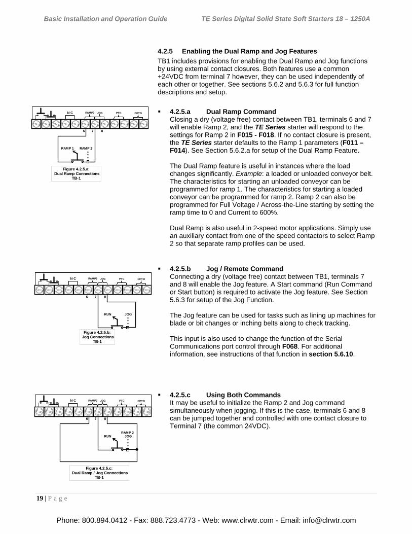
4.2.5 Enabling the Dual Ramp and Jog Features
TB1 includes provisions for enabling the Dual Ramp and Jog functions by using external contact closures. Both features use a common +24VDC from terminal 7 however, they can be used independently of each other or together. See sections 5.6.2 and 5.6.3 for full function descriptions and setup.
4.2.5.a Dual Ramp Command Closing a dry (voltage free) contact between TB1, terminals 6 and 7 will enable Ramp 2, and the TE Series starter will respond to the settings for Ramp 2 in F015 - F018. If no contact closure is present, the TE Series starter defaults to the Ramp 1 parameters (F011 – F014). See Section 5.6.2.a for setup of the Dual Ramp Feature. The Dual Ramp feature is useful in instances where the load changes significantly. Example: a loaded or unloaded conveyor belt. The characteristics for starting an unloaded conveyor can be programmed for ramp 1. The characteristics for starting a loaded conveyor can be programmed for ramp 2. Ramp 2 can also be programmed for Full Voltage / Across-the-Line starting by setting the ramp time to 0 and Current to 600%. Dual Ramp is also useful in 2-speed motor applications. Simply use an auxiliary contact from one of the speed contactors to select Ramp 2 so that separate ramp profiles can be used.
4.2.5.b Jog / Remote Command Connecting a dry (voltage free) contact between TB1, terminals 7 and 8 will enable the Jog feature. A Start command (Run Command or Start button) is required to activate the Jog feature. See Section 5.6.3 for setup of the Jog Function. The Jog feature can be used for tasks such as lining up machines for blade or bit changes or inching belts along to check tracking. This input is also used to change the function of the Serial Communications port control through F068. For additional information, see instructions of that function in section 5.6.10.
4.2.5.c Using Both Commands It may be useful to initialize the Ramp 2 and Jog command simultaneously when jogging. If this is the case, terminals 6 and 8 can be jumped together and controlled with one contact closure to Terminal 7 (the common 24VDC).
N C JOGRAMP2 PTC OPTO
Figure 4.2.5.a: Dual Ramp Connections
TB-1
RAMP 1 RAMP 2
6 7 8
N C JOGRAMP2 PTC OPTO
Figure 4.2.5.b: Jog Connections
TB-1
RUN JOG
6 7 8
N C JOGRAMP2 PTC OPTO
Figure 4.2.5.c: Dual Ramp / Jog Connections
TB-1
RAMP 2RUN JOG
6 7 8
Phone: 800.894.0412 - Fax: 888.723.4773 - Web: www.clrwtr.com - Email: [email protected]
Basic Installation and Operation Guide TE Series Digital Solid State Soft Starters 18 – 1250A
20 | P a g e
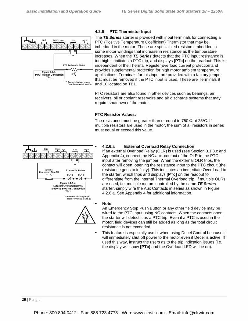
4.2.6 PTC Thermistor Input
The TE Series starter is provided with input terminals for connecting a PTC (Positive Temperature Coefficient) Thermistor that may be imbedded in the motor. These are specialized resistors imbedded in some motor windings that increase in resistance as the temperature increases. When the TE Series detects that the PTC input resistance is too high, it initiates a PTC trip, and displays [PTc] on the readout. This is independent of the Thermal Register overload current protection and provides supplemental protection for high motor ambient temperature applications. Terminals for this input are provided with a factory jumper that must be removed if the PTC input is used. These are Terminals 9 and 10 located on TB1. PTC resistors are also found in other devices such as bearings, air receivers, oil or coolant reservoirs and air discharge systems that may require shutdown of the motor.
PTC Resistor Values:
The resistance must be greater than or equal to 750 at 25ºC. If multiple resistors are used in the motor, the sum of all resistors in series must equal or exceed this value.
4.2.6.a External Overload Relay Connection
If an external Overload Relay (OLR) is used (see Section 3.1.3.c and Appendix 4), connect the NC aux. contact of the OLR to the PTC input after removing the jumper. When the external OLR trips, the contact will open, opening the resistance input to the PTC circuit (the resistance goes to infinity). This indicates an immediate Over Load to the starter, which trips and displays [PTc] on the readout to differentiate from the internal Thermal Overload trip. If multiple OLRs are used, i.e. multiple motors controlled by the same TE Series starter, simply wire the Aux Contacts in series as shown in Figure 4.2.6.a. See Appendix 4 for additional information.
Note:
An Emergency Stop Push Button or any other field device may be wired to the PTC input using NC contacts. When the contacts open, the starter will detect it as a PTC trip. Even if a PTC is used in the motor, field devices can still be added as long as the total circuit resistance is not exceeded.
This feature is especially useful when using Decel Control because it will immediately shut off power to the motor even if Decel is active. If used this way, instruct the users as to the trip indication issues (i.e. the display will show [PTc] and the Overload LED will be on).
+
N C JOGRAMP2 PTC OPTO
Figure 4.2.6: PTC Resistor Connection
TB-1
PTC Resistor in Motor
9 10
**
** Remove factory jumper from Terminals 9 and 10
N C JOGRAMP2 PTC OPTO
Figure 4.2.6.a: External Overload Relay(s)
and/or E-Stop PB ConnectionTB-1
External OL Relays
OLR 1 OLR 2
9 10
OptionalEmergency Stop PB
**
** Remove factory jumper from Terminals 9 and 10
Phone: 800.894.0412 - Fax: 888.723.4773 - Web: www.clrwtr.com - Email: [email protected]
Basic Installation and Operation Guide TE Series Digital Solid State Soft Starters 18 – 1250A
21 | P a g e
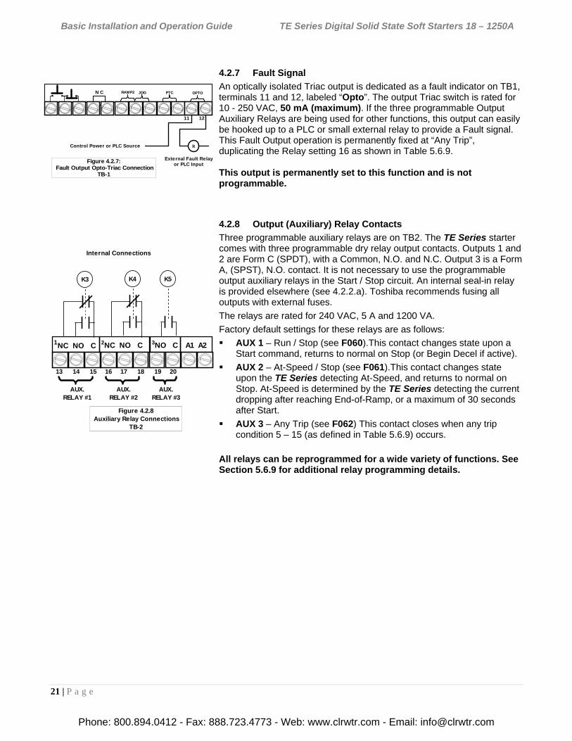
4.2.7 Fault Signal
An optically isolated Triac output is dedicated as a fault indicator on TB1, terminals 11 and 12, labeled “Opto”. The output Triac switch is rated for 10 - 250 VAC, 50 mA (maximum). If the three programmable Output Auxiliary Relays are being used for other functions, this output can easily be hooked up to a PLC or small external relay to provide a Fault signal. This Fault Output operation is permanently fixed at “Any Trip”, duplicating the Relay setting 16 as shown in Table 5.6.9. This output is permanently set to this function and is not programmable.
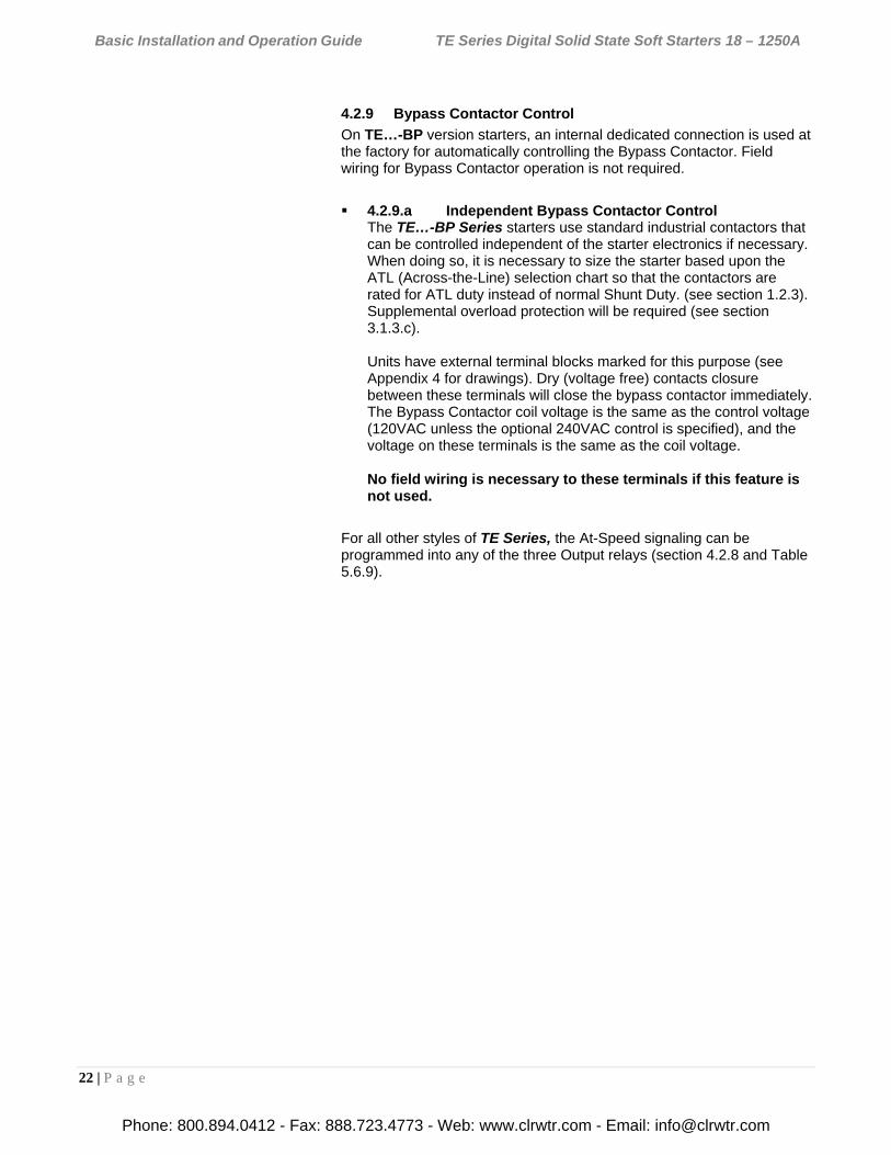
4.2.8 Output (Auxiliary) Relay Contacts
Three programmable auxiliary relays are on TB2. The TE Series starter comes with three programmable dry relay output contacts. Outputs 1 and 2 are Form C (SPDT), with a Common, N.O. and N.C. Output 3 is a Form A, (SPST), N.O. contact. It is not necessary to use the programmable output auxiliary relays in the Start / Stop circuit. An internal seal-in relay is provided elsewhere (see 4.2.2.a). Toshiba recommends fusing all outputs with external fuses.
The relays are rated for 240 VAC, 5 A and 1200 VA.
Factory default settings for these relays are as follows:
AUX 1 – Run / Stop (see F060).This contact changes state upon a Start command, returns to normal on Stop (or Begin Decel if active).
AUX 2 – At-Speed / Stop (see F061).This contact changes state upon the TE Series detecting At-Speed, and returns to normal on Stop. At-Speed is determined by the TE Series detecting the current dropping after reaching End-of-Ramp, or a maximum of 30 seconds after Start.
AUX 3 – Any Trip (see F062) This contact closes when any trip condition 5 – 15 (as defined in Table 5.6.9) occurs.
All relays can be reprogrammed for a wide variety of functions. See Section 5.6.9 for additional relay programming details.
N C JOGRAMP2 PTC OPTO
Figure 4.2.7: Fault Output Opto-Triac Connection
TB-1
11 12
External Fault Relayor PLC Input
RControl Power or PLC Source
K3
Internal Connections
Figure 4.2.8 Auxiliary Relay Connections
TB-2
AUX.RELAY #1
AUX.RELAY #3
AUX.RELAY #2
13 14 15 16 17 18 19 20
1NC NO. C 1A1 A22NC NO. C 3NO. C
K5K4
Phone: 800.894.0412 - Fax: 888.723.4773 - Web: www.clrwtr.com - Email: [email protected]
Basic Installation and Operation Guide TE Series Digital Solid State Soft Starters 18 – 1250A
22 | P a g e
4.2.9 Bypass Contactor Control
On TE…-BP version starters, an internal dedicated connection is used at the factory for automatically controlling the Bypass Contactor. Field wiring for Bypass Contactor operation is not required.
4.2.9.a Independent Bypass Contactor Control The TE…-BP Series starters use standard industrial contactors that can be controlled independent of the starter electronics if necessary. When doing so, it is necessary to size the starter based upon the ATL (Across-the-Line) selection chart so that the contactors are rated for ATL duty instead of normal Shunt Duty. (see section 1.2.3). Supplemental overload protection will be required (see section 3.1.3.c). Units have external terminal blocks marked for this purpose (see Appendix 4 for drawings). Dry (voltage free) contacts closure between these terminals will close the bypass contactor immediately. The Bypass Contactor coil voltage is the same as the control voltage (120VAC unless the optional 240VAC control is specified), and the voltage on these terminals is the same as the coil voltage. No field wiring is necessary to these terminals if this feature is not used.
For all other styles of TE Series, the At-Speed signaling can be programmed into any of the three Output relays (section 4.2.8 and Table 5.6.9).
Phone: 800.894.0412 - Fax: 888.723.4773 - Web: www.clrwtr.com - Email: [email protected]
Basic Installation and Operation Guide TE Series Digital Solid State Soft Starters 18 – 1250A
23 | P a g e
Chapter 5 - Programming
5.1 Introduction
It is best to operate the motor at its full load starting conditions to achieve the proper time, torque and ramp settings. Initial factory settings are set to accommodate general motor applications and provide basic motor protection. Advanced features must be enabled via programming. The only parameter that MUST be set by the user is motor FLA (F001).
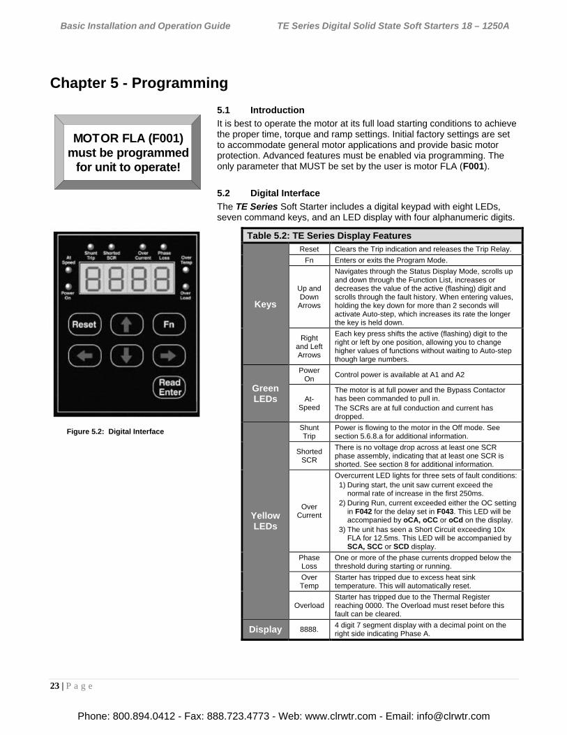
5.2 Digital Interface
The TE Series Soft Starter includes a digital keypad with eight LEDs, seven command keys, and an LED display with four alphanumeric digits.
Figure 5.2: Digital Interface
Table 5.2: TE Series Display Features
Keys
Reset Clears the Trip indication and releases the Trip Relay.
Fn Enters or exits the Program Mode.
Up and Down
Arrows
Navigates through the Status Display Mode, scrolls up and down through the Function List, increases or decreases the value of the active (flashing) digit and scrolls through the fault history. When entering values, holding the key down for more than 2 seconds will activate Auto-step, which increases its rate the longer the key is held down.
Right and LeftArrows
Each key press shifts the active (flashing) digit to the right or left by one position, allowing you to change higher values of functions without waiting to Auto-step though large numbers.
Green LEDs
Power On
Control power is available at A1 and A2
At- Speed
The motor is at full power and the Bypass Contactor has been commanded to pull in. The SCRs are at full conduction and current has dropped.
Yellow LEDs
Shunt Trip
Power is flowing to the motor in the Off mode. See section 5.6.8.a for additional information.
ShortedSCR
There is no voltage drop across at least one SCR phase assembly, indicating that at least one SCR is shorted. See section 8 for additional information.
Over Current
Overcurrent LED lights for three sets of fault conditions: 1) During start, the unit saw current exceed the
normal rate of increase in the first 250ms. 2) During Run, current exceeded either the OC setting
in F042 for the delay set in F043. This LED will be accompanied by oCA, oCC or oCd on the display.
3) The unit has seen a Short Circuit exceeding 10x FLA for 12.5ms. This LED will be accompanied by SCA, SCC or SCD display.
Phase Loss
One or more of the phase currents dropped below the threshold during starting or running.
Over Temp
Starter has tripped due to excess heat sink temperature. This will automatically reset.
Overload Starter has tripped due to the Thermal Register reaching 0000. The Overload must reset before this fault can be cleared.
Display 8888. 4 digit 7 segment display with a decimal point on the right side indicating Phase A.
MOTOR FLA (F001)must be programmed
for unit to operate!
Phone: 800.894.0412 - Fax: 888.723.4773 - Web: www.clrwtr.com - Email: [email protected]
Basic Installation and Operation Guide TE Series Digital Solid State Soft Starters 18 – 1250A
24 | P a g e
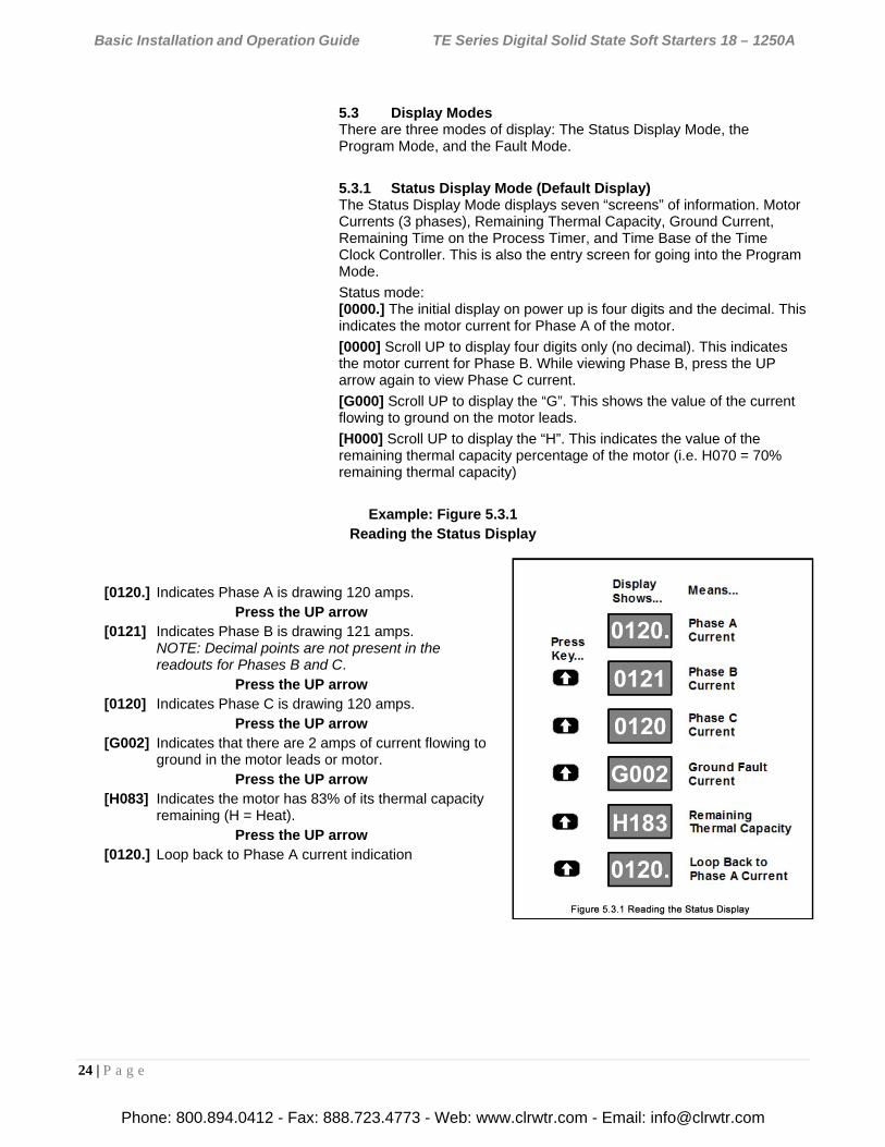
5.3 Display Modes There are three modes of display: The Status Display Mode, the Program Mode, and the Fault Mode.
5.3.1 Status Display Mode (Default Display) The Status Display Mode displays seven “screens” of information. Motor Currents (3 phases), Remaining Thermal Capacity, Ground Current, Remaining Time on the Process Timer, and Time Base of the Time Clock Controller. This is also the entry screen for going into the Program Mode.
Status mode: [0000.] The initial display on power up is four digits and the decimal. This indicates the motor current for Phase A of the motor.
[0000] Scroll UP to display four digits only (no decimal). This indicates the motor current for Phase B. While viewing Phase B, press the UP arrow again to view Phase C current.
[G000] Scroll UP to display the “G”. This shows the value of the current flowing to ground on the motor leads.
[H000] Scroll UP to display the “H”. This indicates the value of the remaining thermal capacity percentage of the motor (i.e. H070 = 70% remaining thermal capacity)
Example: Figure 5.3.1 Reading the Status Display
[0120.] Indicates Phase A is drawing 120 amps. Press the UP arrow
[0121] Indicates Phase B is drawing 121 amps. NOTE: Decimal points are not present in the readouts for Phases B and C.
Press the UP arrow [0120] Indicates Phase C is drawing 120 amps.
Press the UP arrow [G002] Indicates that there are 2 amps of current flowing to
ground in the motor leads or motor. Press the UP arrow
[H083] Indicates the motor has 83% of its thermal capacity remaining (H = Heat).
Press the UP arrow [0120.] Loop back to Phase A current indication
Phone: 800.894.0412 - Fax: 888.723.4773 - Web: www.clrwtr.com - Email: [email protected]
Basic Installation and Operation Guide TE Series Digital Solid State Soft Starters 18 – 1250A
25 | P a g e
Display
PressKey...
Shows...Means...
Default Display:Phase A Current
SelectingFunction #1
Fn 1 Value:FLA = 360A
Return toDefault DisplayWithout Change
0000.
F001
0360
Figure 5.4.1:Viewing a Function's Set Value
0000.
Return to Function# SelectionF001
READENTER
Fn
Fn
Fn
5.4 Program Mode
The starter must be OFF in order to enter the Program Mode.
Use the Program Mode to view or change Function (Fn) settings. To enter the Program Mode, press the [Fn] key once from the Status Screen described in 5.3.1 above. The first time you enter the Program Mode after power has been cycled to the starter, the initial function [F001] should be displayed with the selected digit flashing. If the TE Series starter has been programmed and power to the unit has not been cycled, the readout will display the last function viewed or changed. To change to a different function, use the arrow keys.
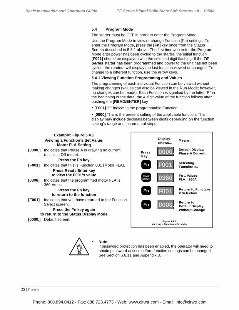
5.4.1 Viewing Function Programming and Values
The programming of each individual Function can be viewed without making changes (values can also be viewed in the Run Mode; however, no changes can be made). Each Function is signified by the letter “F” in the beginning of the data, the 4 digit value of the function follows after pushing the [READ/ENTER] key
• [F001] “F” indicates the programmable Function.
• [0000] This is the present setting of the applicable function. This display may include decimals between digits depending on the function setting’s range and incremental steps.
Example: Figure 5.4.1 Viewing a Function’s Set Value:
Motor FLA Setting [0000.] Indicates that Phase A is drawing no current
(unit is in Off mode). Press the Fn key
[F001] Indicates that this is Function 001 (Motor FLA). Press Read / Enter key
to view the F001’s value [0306] Indicates that the programmed motor FLA is
360 Amps. Press the Fn key
to return to the function [F001] Indicates that you have returned to the Function
Select screen. Press the Fn key again
to return to the Status Display Mode [0000.] Default screen.
Note: If password protection has been enabled, the operator will need to obtain password access before function settings can be changed. See Section 5.6.11 and Appendix 3.
Phone: 800.894.0412 - Fax: 888.723.4773 - Web: www.clrwtr.com - Email: [email protected]
Basic Installation and Operation Guide TE Series Digital Solid State Soft Starters 18 – 1250A
26 | P a g e
Display
PressKey...
Shows...Means...
Phase ACurrent
Function #1Selected
Previous Settingof Function #1
New Value ofFirst Digit
Cursor (flashing)Position Shift
New Value ofSecond Digit
0000.
F001
0048
0049
0049
0059
End Value Accepted(flashes once)
Return toFunction # Display
Figure 5.4.3:Changing a Function Value
Example 1: Setting the Motor FLA
Change FLA from 48 to 59A
F001
READENTER
Fn
READENTER
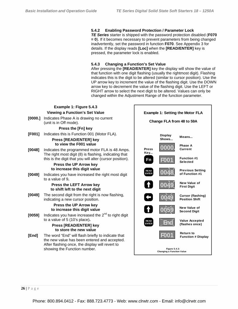
5.4.2 Enabling Password Protection / Parameter Lock TE Series starter is shipped with the password protection disabled (F070 = 0). If it becomes necessary to prevent parameters from being changed inadvertently, set the password in function F070. See Appendix 3 for details. If the display reads [Loc] when the [READ/ENTER] key is pressed, the parameter lock is enabled.
5.4.3 Changing a Function’s Set Value After pressing the [READ/ENTER] key the display will show the value of that function with one digit flashing (usually the rightmost digit). Flashing indicates this is the digit to be altered (similar to cursor position). Use the UP arrow key to increment the value of the flashing digit. Use the DOWN arrow key to decrement the value of the flashing digit. Use the LEFT or RIGHT arrow to select the next digit to be altered. Values can only be changed within the Adjustment Range of the function parameter.
Example 1: Figure 5.4.3
Viewing a Function’s Set Value
[0000.] Indicates Phase A is drawing no current (unit is in Off mode).
Press the [Fn] key
[F001] Indicates this is Function 001 (Motor FLA).
Press [READ/ENTER] key to view the F001 value
[0048] Indicates the programmed motor FLA is 48 Amps. The right most digit (8) is flashing, indicating that this is the digit that you will alter (cursor position).
Press the UP Arrow key to increase this digit value
[0049] Indicates you have increased the right most digit to a value of 9.
Press the LEFT Arrow key to shift left to the next digit
[0049] The second digit from the right is now flashing, indicating a new cursor position.
Press the UP Arrow key to increase this digit value
[0059] Indicates you have increased the 2nd to right digit to a value of 5 (10’s place).
Press [READ/ENTER] key to store the new value
[End] The word “End” will flash briefly to indicate that the new value has been entered and accepted. After flashing once, the display will revert to showing the Function number.
Phone: 800.894.0412 - Fax: 888.723.4773 - Web: www.clrwtr.com - Email: [email protected]
Basic Installation and Operation Guide TE Series Digital Solid State Soft Starters 18 – 1250A
27 | P a g e
Display
PressKey...
Shows...Means...
Phase ACurrent
Function #1Displayed
Previous Settingof Function #3
Value Increasedby 1 Increment
Value Increasedby 1 Increment
0000.
F001
0010
0015
0020
End Value Accepted(flashes once)
Return toFunction # Display
Figure 5.4.3.a:Changing a Function Value by Increments
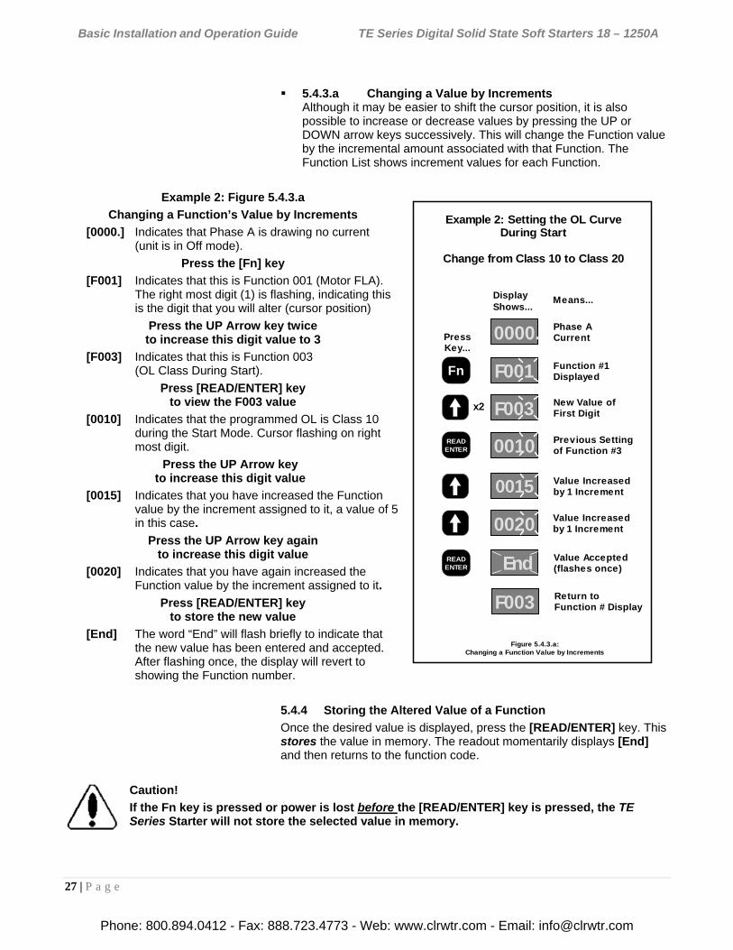
Example 2: Setting the OL CurveDuring Start
Change from Class 10 to Class 20
F003
New Value ofFirst DigitF003x2
Fn
READENTER
READENTER
5.4.3.a Changing a Value by Increments Although it may be easier to shift the cursor position, it is also possible to increase or decrease values by pressing the UP or DOWN arrow keys successively. This will change the Function value by the incremental amount associated with that Function. The Function List shows increment values for each Function.
Example 2: Figure 5.4.3.a
Changing a Function’s Value by Increments
[0000.] Indicates that Phase A is drawing no current (unit is in Off mode).
Press the [Fn] key
[F001] Indicates that this is Function 001 (Motor FLA). The right most digit (1) is flashing, indicating this is the digit that you will alter (cursor position)
Press the UP Arrow key twice to increase this digit value to 3
[F003] Indicates that this is Function 003 (OL Class During Start).
Press [READ/ENTER] key to view the F003 value
[0010] Indicates that the programmed OL is Class 10 during the Start Mode. Cursor flashing on right most digit.
Press the UP Arrow key to increase this digit value
[0015] Indicates that you have increased the Function value by the increment assigned to it, a value of 5 in this case.
Press the UP Arrow key again to increase this digit value
[0020] Indicates that you have again increased the Function value by the increment assigned to it.
Press [READ/ENTER] key to store the new value
[End] The word “End” will flash briefly to indicate that the new value has been entered and accepted. After flashing once, the display will revert to showing the Function number.
5.4.4 Storing the Altered Value of a Function
Once the desired value is displayed, press the [READ/ENTER] key. This stores the value in memory. The readout momentarily displays [End] and then returns to the function code.
Caution!
If the Fn key is pressed or power is lost before the [READ/ENTER] key is pressed, the TE Series Starter will not store the selected value in memory.
Phone: 800.894.0412 - Fax: 888.723.4773 - Web: www.clrwtr.com - Email: [email protected]
Basic Installation and Operation Guide TE Series Digital Solid State Soft Starters 18 – 1250A
28 | P a g e
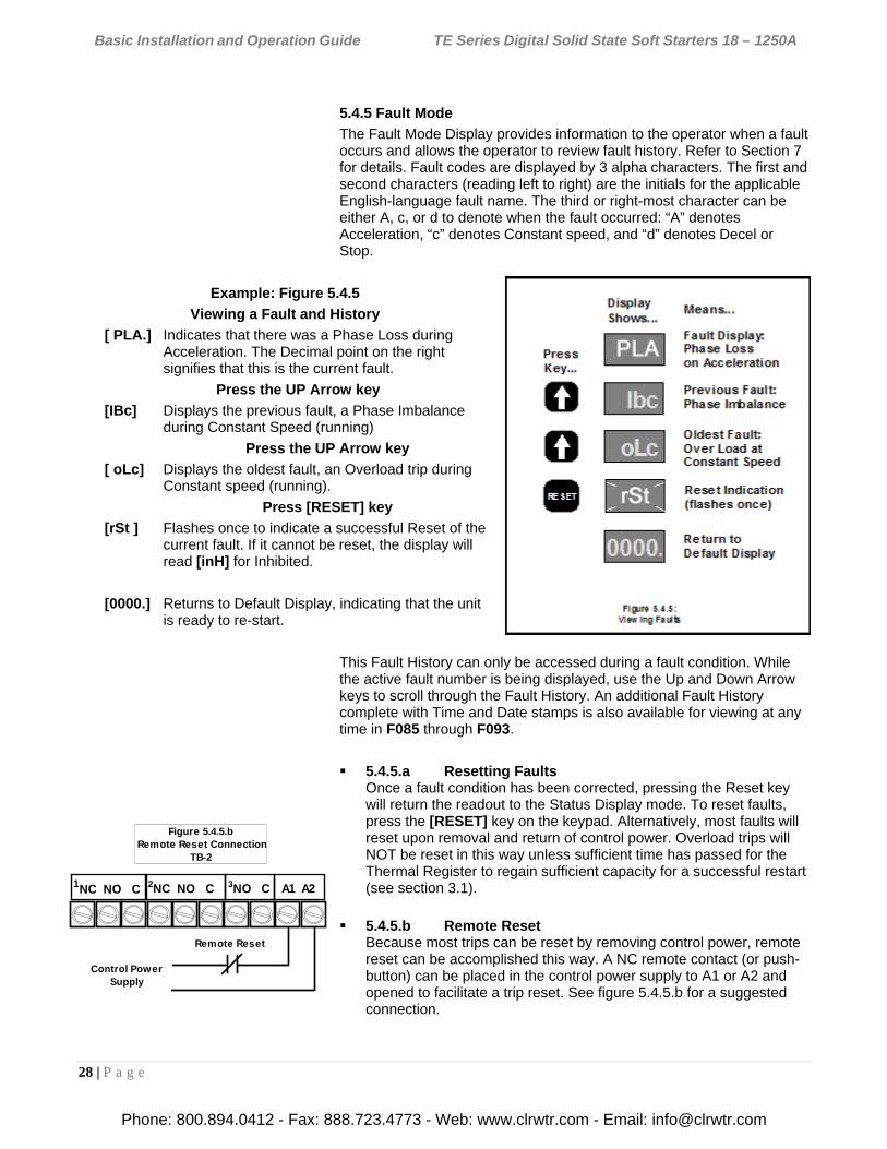
5.4.5 Fault Mode
The Fault Mode Display provides information to the operator when a fault occurs and allows the operator to review fault history. Refer to Section 7 for details. Fault codes are displayed by 3 alpha characters. The first and second characters (reading left to right) are the initials for the applicable English-language fault name. The third or right-most character can be either A, c, or d to denote when the fault occurred: “A” denotes Acceleration, “c” denotes Constant speed, and “d” denotes Decel or Stop.
Example: Figure 5.4.5
Viewing a Fault and History
[ PLA.] Indicates that there was a Phase Loss during Acceleration. The Decimal point on the right signifies that this is the current fault.
Press the UP Arrow key
[IBc] Displays the previous fault, a Phase Imbalance during Constant Speed (running)
Press the UP Arrow key
[ oLc] Displays the oldest fault, an Overload trip during Constant speed (running).
Press [RESET] key
[rSt ] Flashes once to indicate a successful Reset of the current fault. If it cannot be reset, the display will read [inH] for Inhibited.
[0000.] Returns to Default Display, indicating that the unit is ready to re-start.
This Fault History can only be accessed during a fault condition. While the active fault number is being displayed, use the Up and Down Arrow keys to scroll through the Fault History. An additional Fault History complete with Time and Date stamps is also available for viewing at any time in F085 through F093.
5.4.5.a Resetting Faults Once a fault condition has been corrected, pressing the Reset key will return the readout to the Status Display mode. To reset faults, press the [RESET] key on the keypad. Alternatively, most faults will reset upon removal and return of control power. Overload trips will NOT be reset in this way unless sufficient time has passed for the Thermal Register to regain sufficient capacity for a successful restart (see section 3.1).
5.4.5.b Remote Reset Because most trips can be reset by removing control power, remote reset can be accomplished this way. A NC remote contact (or push-button) can be placed in the control power supply to A1 or A2 and opened to facilitate a trip reset. See figure 5.4.5.b for a suggested connection.
Control PowerSupply
Figure 5.4.5.b Remote Reset Connection
TB-2
1NC NO. C 1A1 A22NC NO. C 3NO. C
Remote Reset
Phone: 800.894.0412 - Fax: 888.723.4773 - Web: www.clrwtr.com - Email: [email protected]
Basic Installation and Operation Guide TE Series Digital Solid State Soft Starters 18 – 1250A
29 | P a g e
5.4.5.c Automatic Reset
The TE Series starter provides for automatic reset on certain non-critical faults and Overload. For non-critical fault resets, see section 5.6.8 for program details of F052 and F053. For automatic Overload reset, see section 3.1 and 5.6.1 for programming details.
5.4.5.d Lockout Functions Lockout functions such as Minimum Time Between Starts and Starts per Hour are not true fault conditions. They are based on the internal Real Time Clock (RTC). When control power is removed, the RTC value is quickly stored. Upon return of power, the timer values are updated from the RTC for elapsed time. If the Lockout Time has not expired, the TE Series cannot be started. To reset the Lockout Times for emergency restart, see section 5.6.11, under F071.
5.4.5.e Changing to Default Screen During Fault In some cases it may be necessary to alter programmed parameters in order to test or make changes to clear a fault (such as Phase Loss) or to view the more detailed fault history in F085 – F097. To accomplish this, you must get to the Status Screen so the Fn button becomes active. When in a Fault Screen, pressing the Right or Left Arrow buttons will take you to the Status Screen. From there, you can press the [Fn] key to enter the Programming Mode and move to different functions.
Phone: 800.894.0412 - Fax: 888.723.4773 - Web: www.clrwtr.com - Email: [email protected]
Basic Installation and Operation Guide TE Series Digital Solid State Soft Starters 18 – 1250A
30 | P a g e
5.5 The TE Function List
5.5.1 Motor FLA, Service Factor and Overload Protection Functions
5.5.2 Starting Mode Functions
Fn # Group Function Description Adjustment / Display Range Setting
Increments Factory Setting
Section
F001
Mo
tor
an
d O
verl
oad
In
fo.
Motor Nameplate FLA FLA must be programmed for starter to function.
50-100% of Max Amp Rating. Upper limit of range automatically adjusts downward as Service factor is increased.
1 amp 0
5.6.1 and 3.2
F002 Motor Nameplate Service Factor
1.00 - 1.30 SF 0.05 1.0 SF
F003 Overload Class During Start NEMA / UL Class 5 - 30 5 Class 10
F004 Overload Class During Run NEMA / UL Class 5 - 30 5 Class 10
F005 Overload Reset 0 = Manual 1 = Auto 2 = Disabled Overload
1 0
(Manual)
F006-
F009 Reserved for factory use
Table 5.5.1: Motor and Overload Function Group
Fn # Group Function Description Adjustment / Display Range Setting
Increments Factory Setting
Section
F010
Sta
rtin
g a
nd
Sto
pp
ing
Mo
de
s
Ramp Type Selection: VR = Voltage Ramp CR = Current PID Ramp 1 = Ramp 1, 2 = Ramp 2
Setting 1 = VR1 + VR2 Setting 2 = CR1 + CR2 Setting 3 = VR1 + CR2 Setting 4 = CR1 + VR2
1 1
VR1+VR2
5.6.2 and
Append. 1
F011 Initial Torque (VR) of Ramp 1 0-100% Line Voltage 1% 60%
F012 Initial Torque (CR) of Ramp 1 0-600% Motor Current 1% 200%
F013 Accel Ramp Time of Ramp 1 1-120 seconds 1 second 10
seconds
F014 Max Current Limit of Ramp 1 200 - 600% Motor Current 1% 350%
F015 Initial Torque (VR) of Ramp 2 0-100% Line Voltage 1% 60%
5.6.2, Append.
1 and
4.2.5.b
F016 Initial Torque (CR) of Ramp 2 0-600% Motor Current 1% 200%
F017 Accel Ramp Time of Ramp 2 1-120 seconds 1 second 10
seconds
F018 Max Current Limit of Ramp 2 200 - 600% Motor Current 1% 350%
Table 5.5.2: Starting Mode Function Group
Phone: 800.894.0412 - Fax: 888.723.4773 - Web: www.clrwtr.com - Email: [email protected]
Basic Installation and Operation Guide TE Series Digital Solid State Soft Starters 18 – 1250A
31 | P a g e
5.5.3 Jog Mode Functions
5.5.4 Kick Start Mode Functions
5.5.5 Decel Mode Functions
5.5.6 Restart Function
Fn # Group Function Description Adjustment / Display Range Setting
Increments Factory Setting
Section
F019
Jog
Mo
des
Voltage Jog 5 – 100% Line Voltage 1% 50% 5.6.3 and
4.2.5.b F020 Time of Voltage Jog 1 – 20 Seconds 1 second
10 seconds
F021 Current Jog 100 – 500% Motor Current 1% 150%
Table 5.5.3: Jog Mode Function Group
Fn # Group Function Description Adjustment / Display Range Setting
Increments Factory Setting
Section
F022
Kic
k M
od
e
Kick Start Voltage 0 = Disabled, or 10 - 100% Line Voltage
1% 0
Disabled 5.6.4
F023 Kick Start Time 0.1 - 2 Seconds 0.1second 0.8
seconds
Table 5.5.4: Kick Start Mode Function Group
Fn # Group Function Description Adjustment / Display Range Setting
Increments Factory Setting
Section
F024
Pu
mp
Fle
x D
ecel
Mo
de
Pump Flex Control / Deceleration Ramp
0 = Disabled (coast to stop) 1 = Enabled, except after OL trip 2 = Enabled, continued Decel even
if there is an OL trip
1 0
Disabled
5.6.5 and
Append. 2
F025 Begin Decel Level (BDL), Immediate Drop Down Torque
0 - 100 % of Output Voltage 1% 60%
F026 Decel Shut Off Voltage 0 to (BDL minus 1)% Voltage 1% 30%
F027 Decel Ramp Time 1 – 60 Seconds 1 second 10
seconds
Table 5.5.5: Pump Flex Decel Mode Function Group
Fn # Group Function Description Adjustment / Display Range Setting
Increments Factory Setting
Section
F028
Res
tart
Restart Delay Time (Sequential Start Delay)
0 = Disabled, or 1-999 seconds after a Power Loss (Status can be read in F054)
1 second 0
Disabled 5.6.6
F029 Reserved for Factory Use
Table 5.5.6: Restart Function Group
Phone: 800.894.0412 - Fax: 888.723.4773 - Web: www.clrwtr.com - Email: [email protected]
Basic Installation and Operation Guide TE Series Digital Solid State Soft Starters 18 – 1250A
32 | P a g e
5.5.7 Current and Ground Fault Protection Features
5.5.8 Lockouts, Reset and Internal Protection Functions
Fn # Group Function Description Adjustment / Display Range Setting
Increments Factory Setting
Section
F040
Cu
rren
t an
d G
rou
nd
Fa
ult
Pro
tect
ion
Current Imbalance Trip 0 = Disabled, or 5 - 30% imbalance
1% 0
Disabled
5.6.7
F041 Current Imbalance Trip Delay 1 - 20 seconds 1 second 2
seconds
F042 Over Current Trip 0 = Disabled, or 100 - 300% of motor FLA
1% 0
Disabled
F043 Over Current Trip Delay 1 - 20 seconds 1 second 1 second
F044 Under Current Trip 0 = Disabled, or 10 - 90% of motor FLA
1% 0
Disabled
F045 Under Current Trip Delay 1 - 60 seconds 1 second 2
seconds
F046 Ground Fault Trip 0 = Disabled, or 5 - 90% of CT ratio from Fn 74 1%
0 Disabled
F047 Ground Fault Trip Delay 1 - 60 seconds 1 second 2
seconds
Table 5.5.7: Current and Ground Protection Features Group
Fn # Group Function Description Adjustment / Display Range Setting
Increments Factory Setting
Section
F048
Lo
cko
uts
, Res
et
and
Inte
rnal
Pro
tec
tio
n
Coast Down (Back Spin) Lockout Timer
0 = Disabled, or 1 - 60 minutes 1 minute 0
Disabled
5.6.8 F049 Maximum Starts per Hour 0 = Disabled, or 1 – 10 starts 1 0
Disabled
F050 Minimum Time Between Starts
0 = Disabled, or 1 - 60 minutes 1 minute 0
Disabled
F051 Internal Protection Settings 1 – 127 See“ F051 Definition Table”
1 126 5.6.8.a
F052 Auto Reset on Selected Faults
Fault Preferences 1 – 12 See Table 5.6.7: ”Auto-Reset Selected Faults”
1 4,
Phase Loss only 5.6.8.b
F053 Auto Reset Attempts 0 = Disabled, or 1-10 attempts 1 0
Disabled
F054 Restart Delay Time Value Readout (for F028)
0-999 Minutes 1 0
5.6.8.c
F055 Coast Down Timer Value for F048
1-3600 Seconds 1 0
F056 Starts Per Hour Timer Value for F049
1-3600 Seconds 1 0
F057 Starts Per Hour For F049
1-10 Starts 1 0
F058 Time Value Between Starts for F050
1-3600 Seconds 1 0
F059 Thermal Capacity to Start for F005
0-100 % Thermal Capacity 1 0
Table 5.5.8: Lockouts, Reset and Internal Protection Group
Phone: 800.894.0412 - Fax: 888.723.4773 - Web: www.clrwtr.com - Email: [email protected]
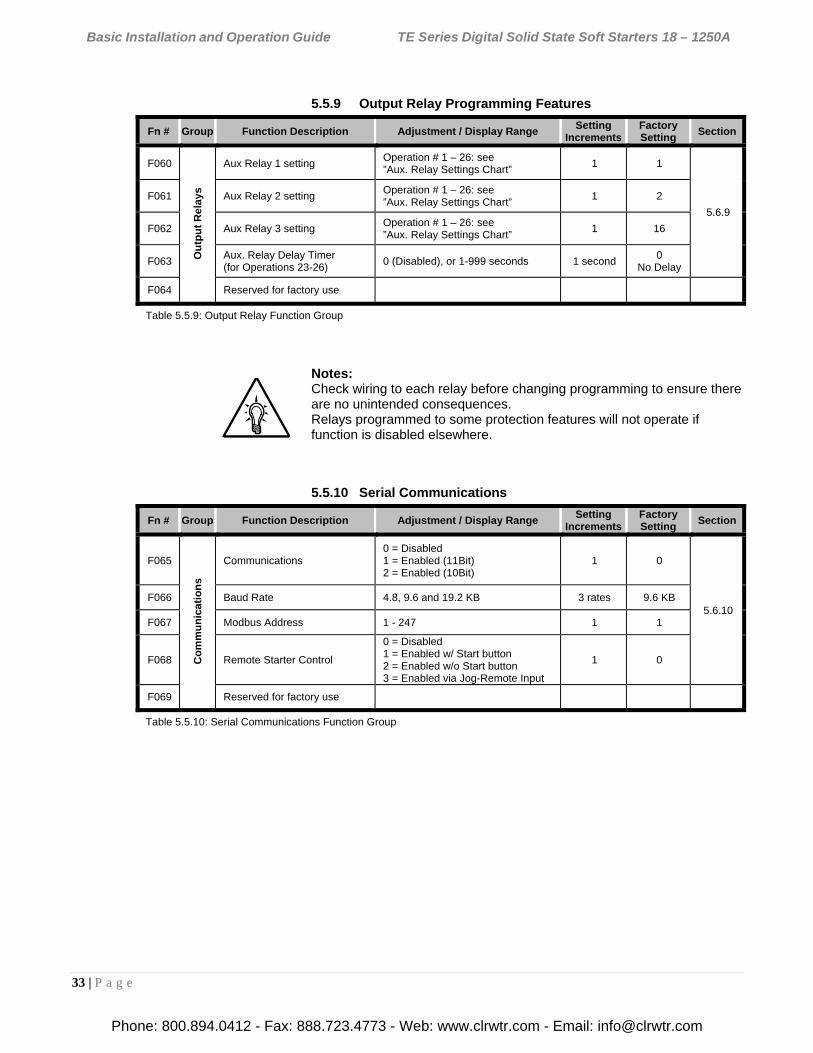
Basic Installation and Operation Guide TE Series Digital Solid State Soft Starters 18 – 1250A
33 | P a g e
5.5.9 Output Relay Programming Features
Notes: Check wiring to each relay before changing programming to ensure there are no unintended consequences. Relays programmed to some protection features will not operate if function is disabled elsewhere.
5.5.10 Serial Communications
Fn # Group Function Description Adjustment / Display Range Setting
Increments Factory Setting
Section
F060
Ou
tpu
t R
elay
s
Aux Relay 1 setting Operation # 1 – 26: see ”Aux. Relay Settings Chart”
1 1
5.6.9
F061 Aux Relay 2 setting Operation # 1 – 26: see ”Aux. Relay Settings Chart”
1 2
F062 Aux Relay 3 setting Operation # 1 – 26: see ”Aux. Relay Settings Chart”
1 16
F063 Aux. Relay Delay Timer (for Operations 23-26)
0 (Disabled), or 1-999 seconds 1 second 0
No Delay
F064 Reserved for factory use
Table 5.5.9: Output Relay Function Group
Fn # Group Function Description Adjustment / Display Range Setting
Increments Factory Setting
Section
F065
Co
mm
un
icat
ion
s
Communications 0 = Disabled 1 = Enabled (11Bit) 2 = Enabled (10Bit)
1 0
5.6.10 F066 Baud Rate 4.8, 9.6 and 19.2 KB 3 rates 9.6 KB
F067 Modbus Address 1 - 247 1 1
F068 Remote Starter Control
0 = Disabled 1 = Enabled w/ Start button 2 = Enabled w/o Start button 3 = Enabled via Jog-Remote Input
1 0
F069 Reserved for factory use
Table 5.5.10: Serial Communications Function Group
Phone: 800.894.0412 - Fax: 888.723.4773 - Web: www.clrwtr.com - Email: [email protected]
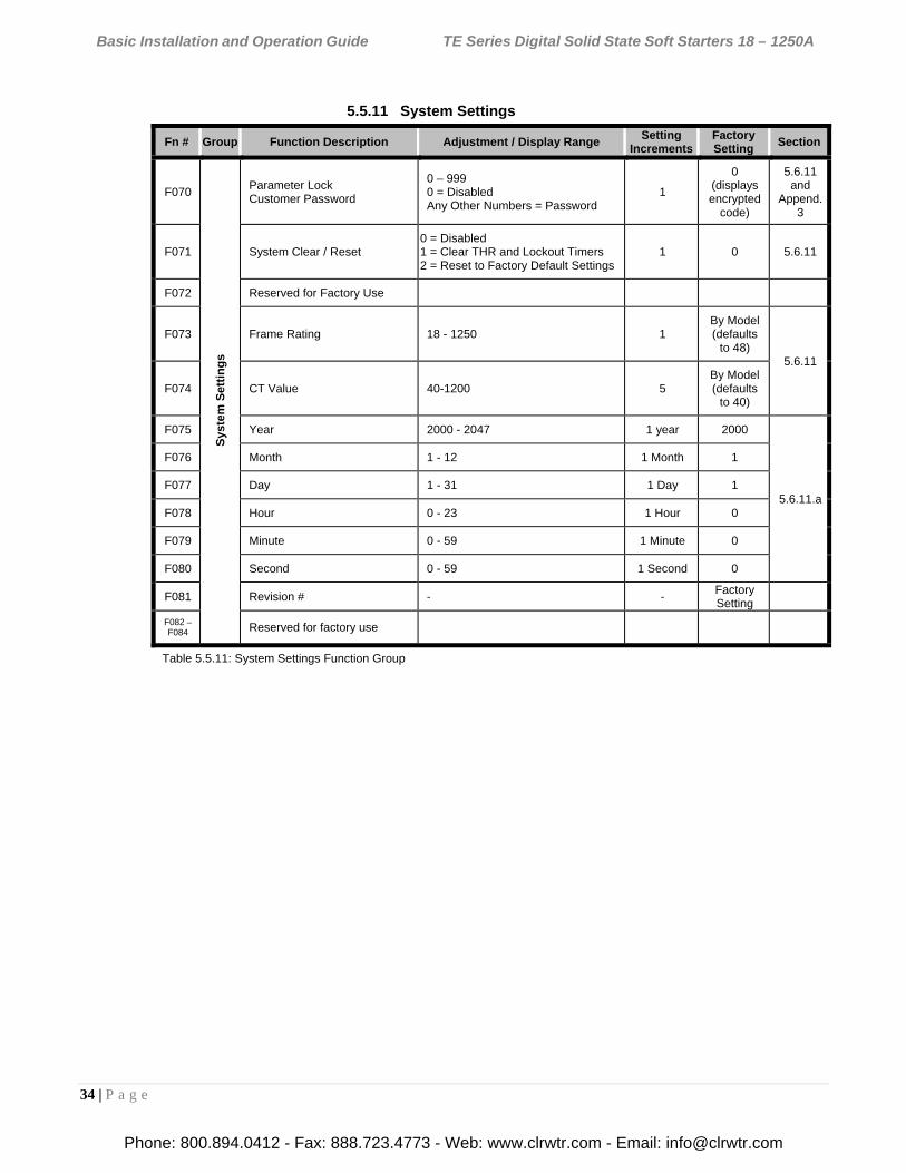
Basic Installation and Operation Guide TE Series Digital Solid State Soft Starters 18 – 1250A
34 | P a g e
5.5.11 System Settings
Fn # Group Function Description Adjustment / Display Range Setting
Increments Factory Setting
Section
F070
Sys
tem
Se
ttin
gs
Parameter Lock Customer Password
0 – 999 0 = Disabled Any Other Numbers = Password
1
0 (displays encrypted
code)
5.6.11 and
Append. 3
F071 System Clear / Reset 0 = Disabled 1 = Clear THR and Lockout Timers 2 = Reset to Factory Default Settings
1 0 5.6.11
F072 Reserved for Factory Use
F073 Frame Rating 18 - 1250 1 By Model (defaults
to 48) 5.6.11
F074 CT Value 40-1200 5 By Model (defaults
to 40)
F075 Year 2000 - 2047 1 year 2000
5.6.11.a
F076 Month 1 - 12 1 Month 1
F077 Day 1 - 31 1 Day 1
F078 Hour 0 - 23 1 Hour 0
F079 Minute 0 - 59 1 Minute 0
F080 Second 0 - 59 1 Second 0
F081 Revision # - - Factory Setting
F082 – F084 Reserved for factory use
Table 5.5.11: System Settings Function Group
Phone: 800.894.0412 - Fax: 888.723.4773 - Web: www.clrwtr.com - Email: [email protected]
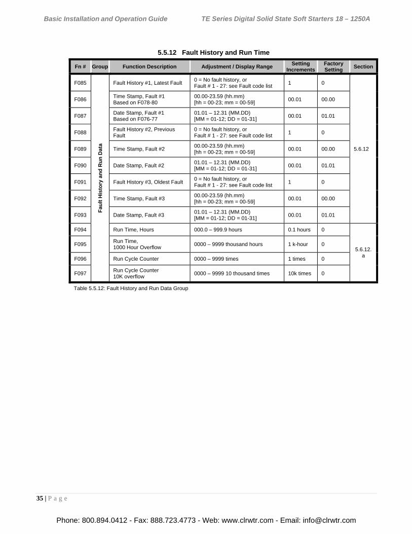
Basic Installation and Operation Guide TE Series Digital Solid State Soft Starters 18 – 1250A
35 | P a g e
5.5.12 Fault History and Run Time
Fn # Group Function Description Adjustment / Display Range Setting
Increments Factory Setting
Section
F085
Fau
lt H
isto
ry a
nd
Ru
n D
ata
Fault History #1, Latest Fault 0 = No fault history, or Fault # 1 - 27: see Fault code list
1 0
5.6.12
F086 Time Stamp, Fault #1 Based on F078-80
00.00-23.59 (hh.mm) [hh = 00-23; mm = 00-59]
00.01 00.00
F087 Date Stamp, Fault #1 Based on F076-77
01.01 – 12.31 (MM.DD) [MM = 01-12; DD = 01-31]
00.01 01.01
F088 Fault History #2, Previous Fault
0 = No fault history, or Fault # 1 - 27: see Fault code list
1 0
F089 Time Stamp, Fault #2 00.00-23.59 (hh.mm) [hh = 00-23; mm = 00-59]
00.01 00.00
F090 Date Stamp, Fault #2 01.01 – 12.31 (MM.DD) [MM = 01-12; DD = 01-31]
00.01 01.01
F091 Fault History #3, Oldest Fault 0 = No fault history, or Fault # 1 - 27: see Fault code list
1 0
F092 Time Stamp, Fault #3 00.00-23.59 (hh.mm) [hh = 00-23; mm = 00-59]
00.01 00.00
F093 Date Stamp, Fault #3 01.01 – 12.31 (MM.DD) [MM = 01-12; DD = 01-31]
00.01 01.01
F094 Run Time, Hours 000.0 – 999.9 hours 0.1 hours 0
5.6.12.a
F095 Run Time, 1000 Hour Overflow
0000 – 9999 thousand hours 1 k-hour 0
F096 Run Cycle Counter 0000 – 9999 times 1 times 0
F097 Run Cycle Counter 10K overflow
0000 – 9999 10 thousand times 10k times 0
Table 5.5.12: Fault History and Run Data Group
Phone: 800.894.0412 - Fax: 888.723.4773 - Web: www.clrwtr.com - Email: [email protected]
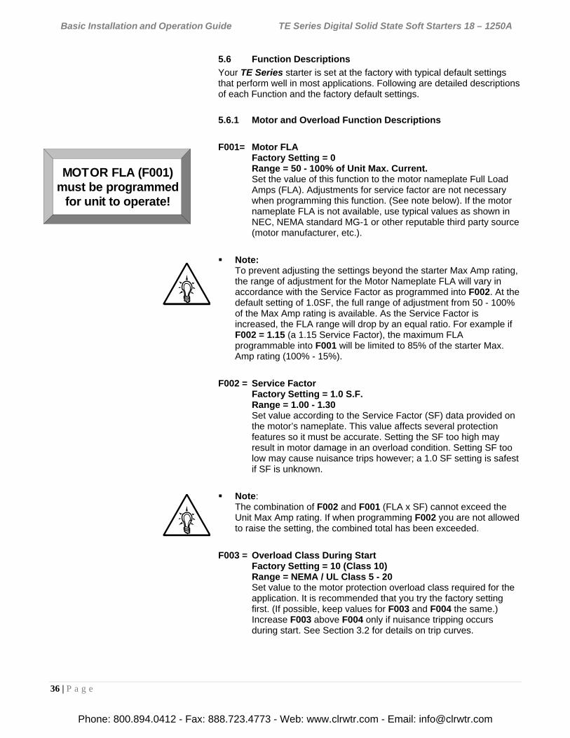
Basic Installation and Operation Guide TE Series Digital Solid State Soft Starters 18 – 1250A
36 | P a g e
5.6 Function Descriptions
Your TE Series starter is set at the factory with typical default settings that perform well in most applications. Following are detailed descriptions of each Function and the factory default settings.
5.6.1 Motor and Overload Function Descriptions
F001= Motor FLA Factory Setting = 0 Range = 50 - 100% of Unit Max. Current. Set the value of this function to the motor nameplate Full Load Amps (FLA). Adjustments for service factor are not necessary when programming this function. (See note below). If the motor nameplate FLA is not available, use typical values as shown in NEC, NEMA standard MG-1 or other reputable third party source (motor manufacturer, etc.).
Note: To prevent adjusting the settings beyond the starter Max Amp rating, the range of adjustment for the Motor Nameplate FLA will vary in accordance with the Service Factor as programmed into F002. At the default setting of 1.0SF, the full range of adjustment from 50 - 100% of the Max Amp rating is available. As the Service Factor is increased, the FLA range will drop by an equal ratio. For example if F002 = 1.15 (a 1.15 Service Factor), the maximum FLA programmable into F001 will be limited to 85% of the starter Max. Amp rating (100% - 15%).
F002 = Service Factor Factory Setting = 1.0 S.F. Range = 1.00 - 1.30 Set value according to the Service Factor (SF) data provided on the motor’s nameplate. This value affects several protection features so it must be accurate. Setting the SF too high may result in motor damage in an overload condition. Setting SF too low may cause nuisance trips however; a 1.0 SF setting is safest if SF is unknown.
Note: The combination of F002 and F001 (FLA x SF) cannot exceed the Unit Max Amp rating. If when programming F002 you are not allowed to raise the setting, the combined total has been exceeded.
F003 = Overload Class During Start Factory Setting = 10 (Class 10) Range = NEMA / UL Class 5 - 20 Set value to the motor protection overload class required for the application. It is recommended that you try the factory setting first. (If possible, keep values for F003 and F004 the same.) Increase F003 above F004 only if nuisance tripping occurs during start. See Section 3.2 for details on trip curves.
MOTOR FLA (F001)must be programmed
for unit to operate!
Phone: 800.894.0412 - Fax: 888.723.4773 - Web: www.clrwtr.com - Email: [email protected]
Basic Installation and Operation Guide TE Series Digital Solid State Soft Starters 18 – 1250A
37 | P a g e
F004 = Overload Class During Run Factory Setting = 10 (Class 10) Range = 5 - 30 NEMA / UL Class Set value according to the instructions provided by your motor / equipment manufacturer. This trip curve will not be enabled until the motor has reached full speed.
F005 = Overload Reset Factory Setting = 0 (Manual) Range = 0 – 2 Set value to determine starter behavior after an overload condition has cleared. When set to 0 = Manual, the operator must press the [RESET] key before restarting the motor. Once the motor windings have cooled sufficiently AND the [RESET] key is pressed, the unit will accept a restart command. When set to 1 = Automatic mode, and once sufficient time has elapsed allowing motor windings to cool, the motor will be restarted upon a start command. If 2-wire control is used, the unit will restart immediately. When set to 2 = Disabled Overload, the TE Series will not trip on Motor Thermal Overload. This is provided for applications where either an external Overload Relay or Motor Protection Relay is used, or where multiple motors are connected and each one requires having an individual Overload Relay. See Appendix 4 for more details.
WARNING:
Setting F005 = 1 (Automatic) may present significant operational risk.
When F005 = 2 (Disabled Overload), a separate external thermal overload protection device must be in the circuit.
Note: Because of the risk of fire or equipment damage, cycling control power will NOT reset an Overload Trip. If F005 = 2 (Automatic Reset), cycling control power will allow reset ONLY if the Thermal Register has determined that the motor has regained sufficient thermal capacity to allow it to restart successfully.
F006 - F009 = Reserved
Phone: 800.894.0412 - Fax: 888.723.4773 - Web: www.clrwtr.com - Email: [email protected]
Basic Installation and Operation Guide TE Series Digital Solid State Soft Starters 18 – 1250A
38 | P a g e
5.6.2 Starting Mode
The TE Series is capable of several different starting modes, but is set from the factory for the most common applications. A second ramp profile is available for use should it be required. Unless wired to do so, the TE Series defaults to Ramp 1. This section describes functions for Ramp 1, with references to function numbers that do the same thing for Ramp 2 (if required). Refer to Appendix 2 for a detailed description of the differences in Ramp Profiles and their uses. All current percentages are based on the Motor FLA as programmed in F001.
F010 = Ramp Profile Selection Factory Setting = 1 Range = 1 – 4 This Function selects the type of Ramp Profile desired. Ramp profiles can be either Voltage Ramp or Current Ramp. See Appendix 2 for details. Each Ramp Profile consists of 3 settings: Initial Torque, Ramp Time and Maximum Current Limit. Because there are two ramps available, there are 4 settings to cover the combinations of profiles possible. If you are not using the 2nd ramp, the TE Series will ignore all settings in reference to Ramp 2.
Ramp 1
(Dual Ramp Input Open) Ramp 2
(Dual Ramp Input Closed)
F010 Setting
Ramp Profile Ramp Profile
1 Voltage Voltage 2 Current Current 3 Voltage Current 4 Current Voltage
Table 5.6.2: Ramp Type selection Settings
Select Voltage Ramp by setting F010 = 1 (factory default) When Voltage Ramp is selected, Set Initial Torque (Voltage) with F011 (see below) Set Ramp Time with F013 (see below) Set Maximum Current Limit with F014 (see below)
Or;
Select Current Ramp by setting F010 = 2 When Current Ramp is selected, Set Initial Torque (Current) with F012 (see below) Set Ramp Time with F013 (see below) Set Maximum Current Limit with F014 (see below)
Note: When either Ramp is set to “Voltage Ramp”, the corresponding “Initial Torque (Current)” setting is ignored. Conversely, when set to “Current Ramp”, the “Initial Torque (Voltage)” is ignored.
Phone: 800.894.0412 - Fax: 888.723.4773 - Web: www.clrwtr.com - Email: [email protected]
Basic Installation and Operation Guide TE Series Digital Solid State Soft Starters 18 – 1250A
39 | P a g e
F011 = Initial Voltage of Ramp 1 Factory Setting = 60% Range = 0 - 100% Sets the initial voltage of ramp 1 when F010 = 1 or 3. The initial torque level should be set to provide just enough torque to make the motor shaft begin to rotate while preventing torque shock damage to mechanical components.
F012 = Initial Current of Ramp 1 Factory Setting = 200% Range = 0 - 600% Sets the initial current of ramp 1 when F010 = 2 or 4. The initial torque level should be set to provide just enough torque to make the motor shaft begin to rotate while preventing torque shock damage to mechanical components.
F013 = Accel Ramp Time of Ramp 1 Factory Setting = 10 seconds Range = 1 - 120 seconds Sets the time between the initial torque set with F011 or F012 and either the Max Current Limit set with F014or full output voltage. Set the time to enable soft starts without stalls. Also, consider the motor’s application. For example, centrifugal pumps may require a shorter ramp time.
Note: Ramp time is affected by the following conditions:
1. Current limit will extend the ramp time if the motor does not reach full speed while in current limit mode.
2. Anti-oscillation circuit may shorten the ramp time if the motor reaches full speed before end of ramp.
F014 = Max Current Limit of Ramp 1 Factory Setting = 350% Range = 200 - 600% Sets the maximum motor current that the TE Series starter will allow during Ramp 1. This limit applies to both voltage and current ramping. Current will be limited to this setting until either the motor reaches full speed or the over load protection feature trips (F003).
Phone: 800.894.0412 - Fax: 888.723.4773 - Web: www.clrwtr.com - Email: [email protected]
Basic Installation and Operation Guide TE Series Digital Solid State Soft Starters 18 – 1250A
40 | P a g e
5.6.2.a Ramp 2 (user-optional ramp) This ramp is selected by closing the input for Ramp 2, TB1 – terminals 5 & 6 (see section 4.2.5). If this input is left open, the TE Series will respond only to Ramp 1 settings as listed above. Since ramp 2 is always used as an alternate to the default Ramp 1, different combinations of ramp profiles can be selected in F010. Refer to Appendix 1 for additional information on ramp profiles.
F015 = Initial Torque (Voltage) of Ramp 2 Factory Setting = 60% Range = 0 - 100% Sets the initial voltage of Ramp 2 when F010 = 1 or 4. The initial torque level should be set to provide just enough torque to make the motor shaft begin to rotate while preventing torque shock damage to mechanical components.
F016 = Initial Torque (Current) of Ramp 2 Factory Setting = 200% Range = 0 - 600% Sets the initial current of Ramp 2 when F010 = 2 or 3. The initial torque level should be set to provide just enough torque to make the motor shaft begin to rotate while preventing torque shock damage to mechanical components.
F017 = Accel Ramp Time of Ramp 2 Factory Setting = 10 seconds Range = 1 - 120 seconds Sets the time between the initial torque set with F015 or F016 and either the Max Current Limit set with F018 or full output voltage. Set the time to enable soft starts without stalls. Also consider the motor’s application. For example, centrifugal pumps may require a shorter time. See notes for F013 for more details.
F018 = Max Current Limit of Ramp 2 Factory Setting = 350% Range = 200 - 600% Sets the maximum motor current that the TE Series starter will allow during ramp 2. (This limit applies to both voltage and current-type ramping.) The current will be limited to this setting until either the motor reaches full speed or the over load protection feature trips (F003).
Note: Ramp 2 is often useful as a “bump start” or as a temporary Across-the-Line start mode. Consult Appendix 1 for details.
Phone: 800.894.0412 - Fax: 888.723.4773 - Web: www.clrwtr.com - Email: [email protected]
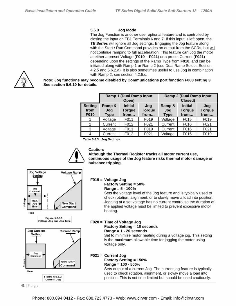
Basic Installation and Operation Guide TE Series Digital Solid State Soft Starters 18 – 1250A
41 | P a g e
5.6.3 Jog Mode The Jog Function is another user optional feature and is controlled by closing the input on TB1 Terminals 6 and 7. If this input is left open, the TE Series will ignore all Jog settings. Engaging the Jog feature along with the Start / Run Command provides an output from the SCRs, but will not continue ramping to full acceleration. This feature can Jog the motor at either a preset Voltage (F019 – F021) or a preset Current (F021) depending upon the settings of the Ramp Type from F010, and can be initiated along with Ramp 1 or Ramp 2 (see Dual Ramp Select, Section 4.2.5 and 5.6.2.a). It is also sometimes useful to use Jog in combination with Ramp 2, see section 4.2.5.c.
Note: Jog functions may become disabled by Communications port function F068 setting 3. See section 5.6.10 for details.
Ramp 1 (Dual Ramp Input
Open) Ramp 2 (Dual Ramp Input
Closed) Setting
from F010
Ramp & Jog Type
Initial Torque from…
Jog Torque from…
Ramp & Jog Type
Initial Torque from…
Jog Torque from…
1 Voltage F011 F019 Voltage F015 F019 2 Current F012 F021 Current F016 F021 3 Voltage F011 F019 Current F016 F021 4 Current F012 F021 Voltage F015 F019
Table 5.6.3: Jog Settings
Caution: Although the Thermal Register tracks all motor current use, continuous usage of the Jog feature risks thermal motor damage or nuisance tripping.
F019 = Voltage Jog Factory Setting = 50% Range = 5 - 100% Sets the voltage level of the Jog feature and is typically used to check rotation, alignment, or to slowly move a load into position. Jogging at a set voltage has no current control so the duration of the applied voltage must be limited to prevent excessive motor heating.
F020 = Time of Voltage Jog Factory Setting = 10 seconds Range = 1 - 20 seconds Set to minimize motor heating during a voltage jog. This setting is the maximum allowable time for jogging the motor using voltage only.
F021 = Current Jog Factory Setting = 150% Range = 100 - 500% Sets output of a current Jog. The current jog feature is typically used to check rotation, alignment, or slowly move a load into position. This is not time-limited but should be used cautiously.
Jog VoltageSetting
Voltage Ramp
Vo
lta
ge
Time
Figure 5.6.3.1:Voltage Jog and Jog Time
New StartCommand
Max.JogTime
JogCommand
Jog CurrentSetting
Current Ramp
Cu
rre
nt
Time
Figure 5.6.3.2:Current Jog
New StartCommand
JogCommand
Phone: 800.894.0412 - Fax: 888.723.4773 - Web: www.clrwtr.com - Email: [email protected]
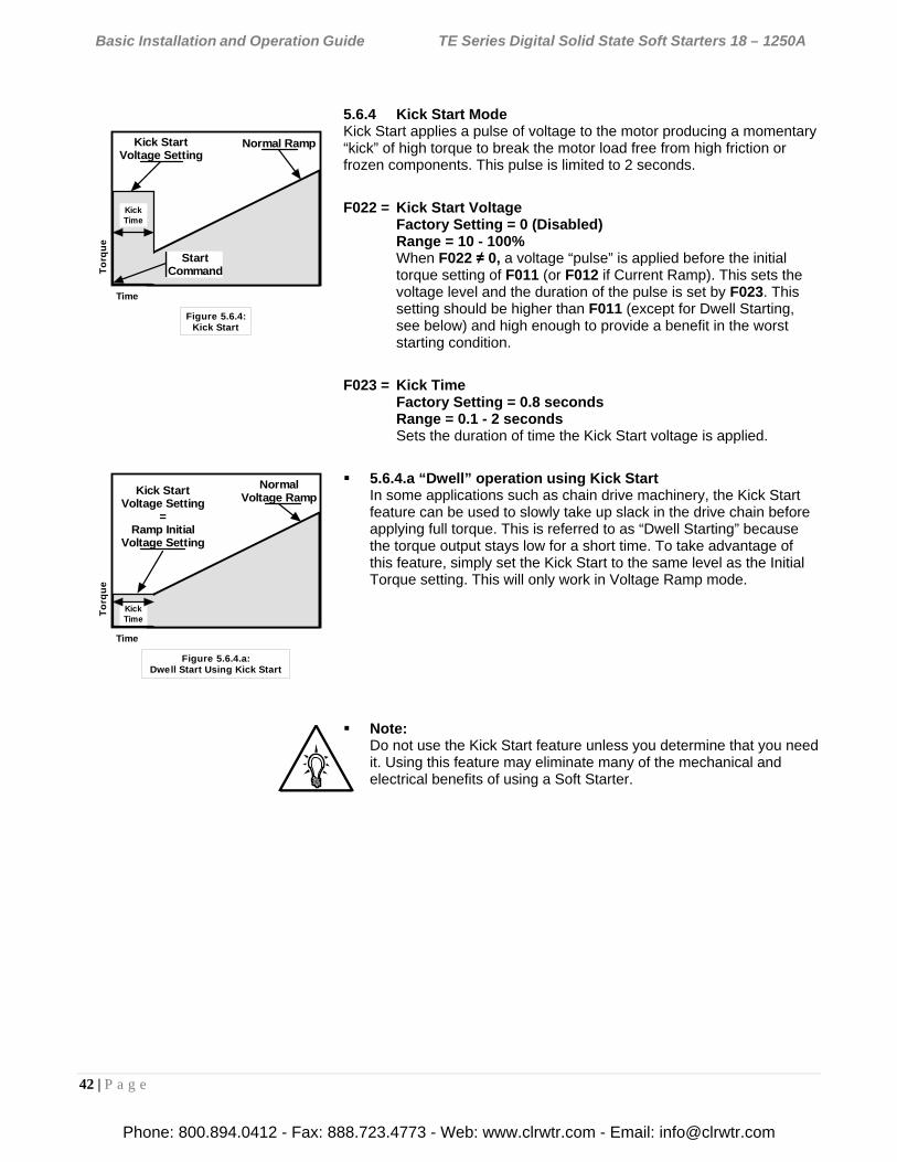
Basic Installation and Operation Guide TE Series Digital Solid State Soft Starters 18 – 1250A
42 | P a g e
5.6.4 Kick Start Mode Kick Start applies a pulse of voltage to the motor producing a momentary “kick” of high torque to break the motor load free from high friction or frozen components. This pulse is limited to 2 seconds.
F022 = Kick Start Voltage Factory Setting = 0 (Disabled) Range = 10 - 100% When F022 ≠ 0, a voltage “pulse” is applied before the initial torque setting of F011 (or F012 if Current Ramp). This sets the voltage level and the duration of the pulse is set by F023. This setting should be higher than F011 (except for Dwell Starting, see below) and high enough to provide a benefit in the worst starting condition.
F023 = Kick Time Factory Setting = 0.8 seconds Range = 0.1 - 2 seconds Sets the duration of time the Kick Start voltage is applied.
5.6.4.a “Dwell” operation using Kick Start In some applications such as chain drive machinery, the Kick Start feature can be used to slowly take up slack in the drive chain before applying full torque. This is referred to as “Dwell Starting” because the torque output stays low for a short time. To take advantage of this feature, simply set the Kick Start to the same level as the Initial Torque setting. This will only work in Voltage Ramp mode.
Note: Do not use the Kick Start feature unless you determine that you need it. Using this feature may eliminate many of the mechanical and electrical benefits of using a Soft Starter.
Figure 5.6.4:Kick Start
Kick StartVoltage Setting
Normal Ramp
To
rqu
e
Time
StartCommand
KickTime
Figure 5.6.4.a:Dwell Start Using Kick Start
Kick StartVoltage Setting
=Ramp Initial
Voltage Setting
NormalVoltage Ramp
To
rqu
e
Time
KickTime
Phone: 800.894.0412 - Fax: 888.723.4773 - Web: www.clrwtr.com - Email: [email protected]
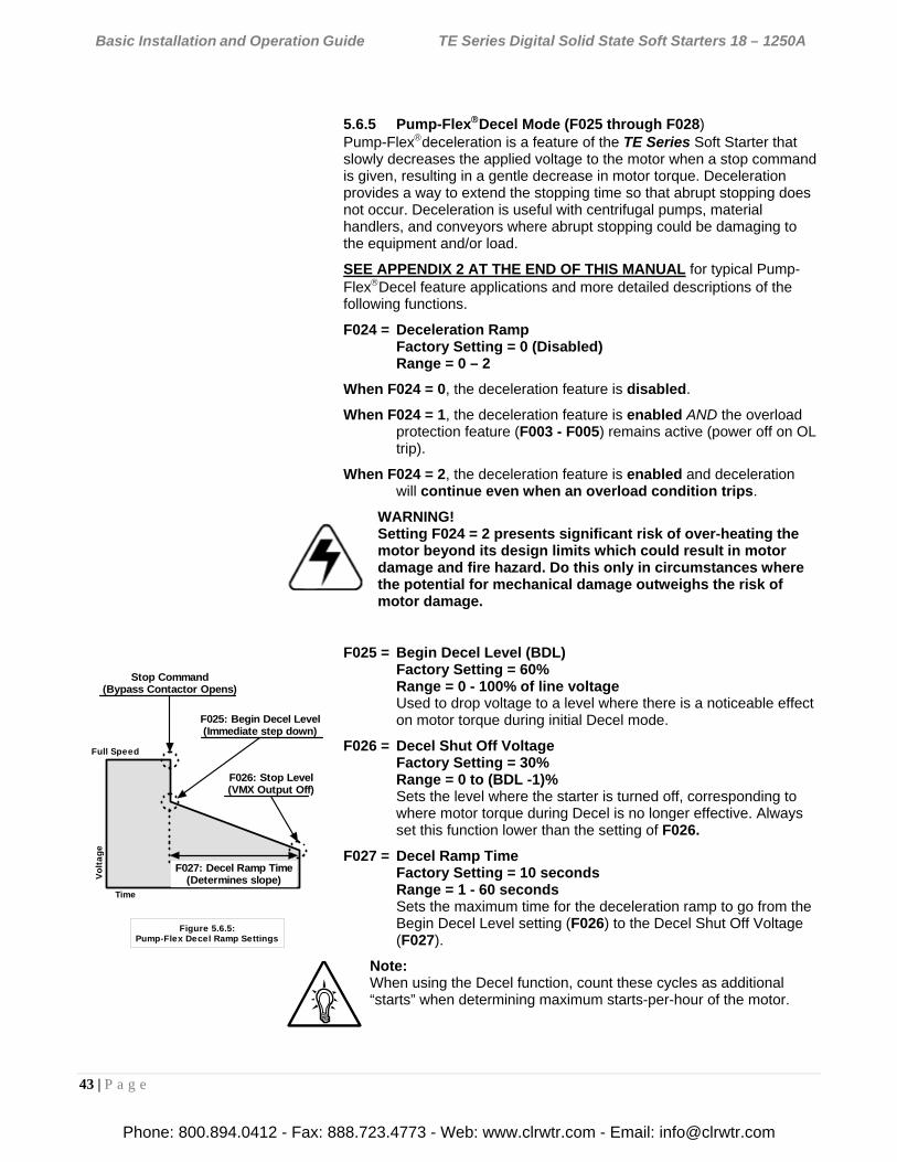
Basic Installation and Operation Guide TE Series Digital Solid State Soft Starters 18 – 1250A
43 | P a g e
5.6.5 Pump-FlexDecel Mode (F025 through F028) Pump-Flexdeceleration is a feature of the TE Series Soft Starter that slowly decreases the applied voltage to the motor when a stop command is given, resulting in a gentle decrease in motor torque. Deceleration provides a way to extend the stopping time so that abrupt stopping does not occur. Deceleration is useful with centrifugal pumps, material handlers, and conveyors where abrupt stopping could be damaging to the equipment and/or load.
SEE APPENDIX 2 AT THE END OF THIS MANUAL for typical Pump-FlexDecel feature applications and more detailed descriptions of the following functions.
F024 = Deceleration Ramp Factory Setting = 0 (Disabled) Range = 0 – 2
When F024 = 0, the deceleration feature is disabled.
When F024 = 1, the deceleration feature is enabled AND the overload protection feature (F003 - F005) remains active (power off on OL trip).
When F024 = 2, the deceleration feature is enabled and deceleration will continue even when an overload condition trips.
WARNING! Setting F024 = 2 presents significant risk of over-heating the motor beyond its design limits which could result in motor damage and fire hazard. Do this only in circumstances where the potential for mechanical damage outweighs the risk of motor damage.
F025 = Begin Decel Level (BDL) Factory Setting = 60% Range = 0 - 100% of line voltage Used to drop voltage to a level where there is a noticeable effect on motor torque during initial Decel mode.
F026 = Decel Shut Off Voltage Factory Setting = 30% Range = 0 to (BDL -1)% Sets the level where the starter is turned off, corresponding to where motor torque during Decel is no longer effective. Always set this function lower than the setting of F026.
F027 = Decel Ramp Time Factory Setting = 10 seconds Range = 1 - 60 seconds Sets the maximum time for the deceleration ramp to go from the Begin Decel Level setting (F026) to the Decel Shut Off Voltage (F027).
Note: When using the Decel function, count these cycles as additional “starts” when determining maximum starts-per-hour of the motor.
Stop Command(Bypass Contactor Opens)
F025: Begin Decel Level(Immediate step down)
F026: Stop Level(VMX Output Off)
Vo
lta
ge
Time
F027: Decel Ramp Time(Determines slope)
Figure 5.6.5:Pump-Flex Decel Ramp Settings
Full Speed
Phone: 800.894.0412 - Fax: 888.723.4773 - Web: www.clrwtr.com - Email: [email protected]
Basic Installation and Operation Guide TE Series Digital Solid State Soft Starters 18 – 1250A
44 | P a g e
Caution! Decel is THE OPPOSITE of braking. Enabling the Decel feature will make the motor take LONGER to stop than if it were simply turned off.
5.6.6 Restart Delay The TE Series can be programmed to delay restarting upon restoration of line power after an outage. This allows multiple units to be programmed to restart at staggered times in an effort to avoid causing additional problems with the power supply system. Another term for this is “Sequential Start Delay”.
F028 = Restart Delay Time Factory Setting = 0 (Disabled) Range = 0 = Disabled (no delay), or 1 - 999 seconds Sets a delay time before the starter can be restarted after a complete loss of power. Use this if multiple motors are connected to a supply system that may have trouble providing adequate power to restart them all at the same time. By using different Restart Delay Times on each unit, a sequential restart can be achieved.
Note: This is similar to the Coast Down Lockout Timer in F048, however it only activates on Power Loss.
F029 = Reserved
Phone: 800.894.0412 - Fax: 888.723.4773 - Web: www.clrwtr.com - Email: [email protected]
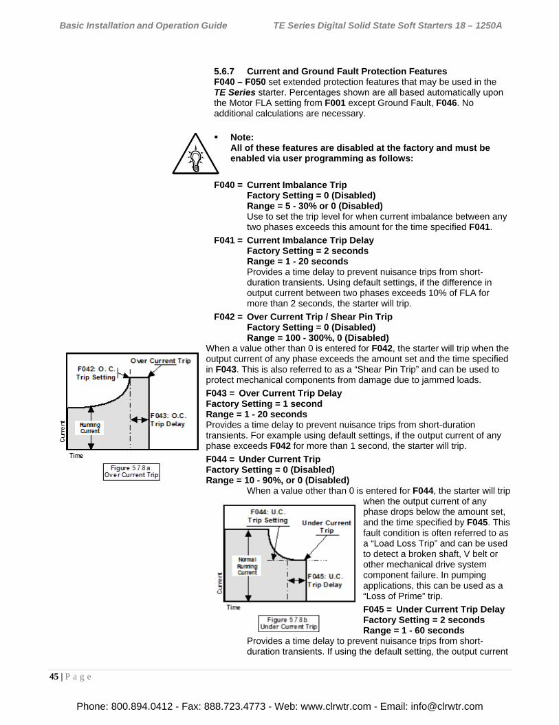
Basic Installation and Operation Guide TE Series Digital Solid State Soft Starters 18 – 1250A
45 | P a g e
5.6.7 Current and Ground Fault Protection Features F040 – F050 set extended protection features that may be used in the TE Series starter. Percentages shown are all based automatically upon the Motor FLA setting from F001 except Ground Fault, F046. No additional calculations are necessary.
Note: All of these features are disabled at the factory and must be enabled via user programming as follows:
F040 = Current Imbalance Trip Factory Setting = 0 (Disabled) Range = 5 - 30% or 0 (Disabled) Use to set the trip level for when current imbalance between any two phases exceeds this amount for the time specified F041.
F041 = Current Imbalance Trip Delay Factory Setting = 2 seconds Range = 1 - 20 seconds Provides a time delay to prevent nuisance trips from short-duration transients. Using default settings, if the difference in output current between two phases exceeds 10% of FLA for more than 2 seconds, the starter will trip.
F042 = Over Current Trip / Shear Pin Trip Factory Setting = 0 (Disabled) Range = 100 - 300%, 0 (Disabled)
When a value other than 0 is entered for F042, the starter will trip when the output current of any phase exceeds the amount set and the time specified in F043. This is also referred to as a “Shear Pin Trip” and can be used to protect mechanical components from damage due to jammed loads.
F043 = Over Current Trip Delay Factory Setting = 1 second Range = 1 - 20 seconds Provides a time delay to prevent nuisance trips from short-duration transients. For example using default settings, if the output current of any phase exceeds F042 for more than 1 second, the starter will trip.
F044 = Under Current Trip Factory Setting = 0 (Disabled) Range = 10 - 90%, or 0 (Disabled)
When a value other than 0 is entered for F044, the starter will trip when the output current of any phase drops below the amount set, and the time specified by F045. This fault condition is often referred to as a “Load Loss Trip” and can be used to detect a broken shaft, V belt or other mechanical drive system component failure. In pumping applications, this can be used as a “Loss of Prime” trip.
F045 = Under Current Trip Delay Factory Setting = 2 seconds Range = 1 - 60 seconds
Provides a time delay to prevent nuisance trips from short-duration transients. If using the default setting, the output current
Phone: 800.894.0412 - Fax: 888.723.4773 - Web: www.clrwtr.com - Email: [email protected]
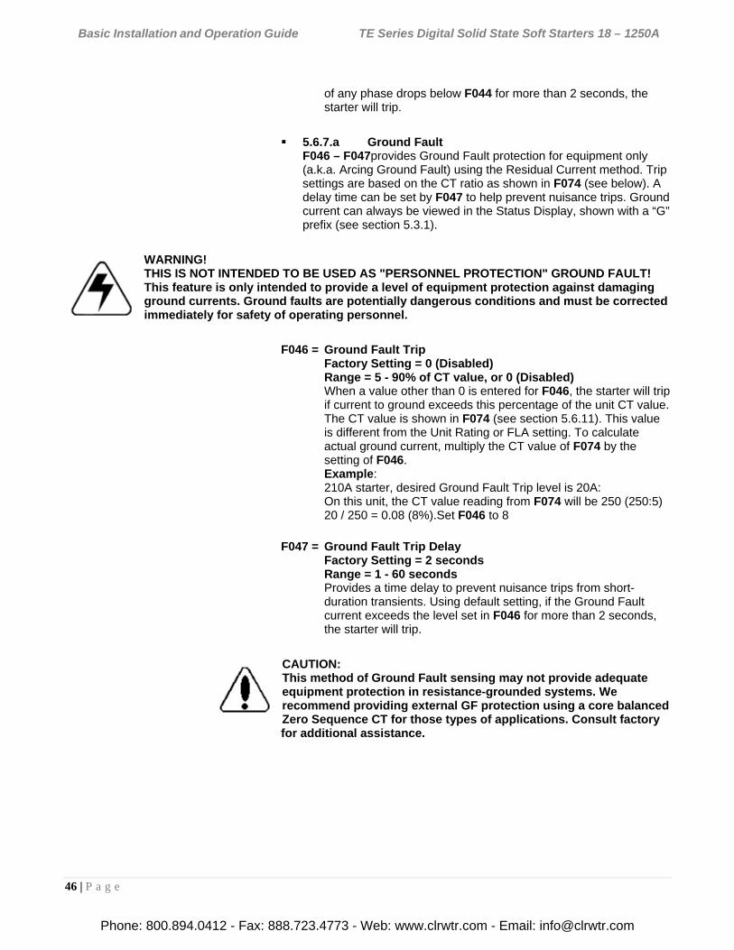
Basic Installation and Operation Guide TE Series Digital Solid State Soft Starters 18 – 1250A
46 | P a g e
of any phase drops below F044 for more than 2 seconds, the starter will trip.
5.6.7.a Ground Fault F046 – F047provides Ground Fault protection for equipment only (a.k.a. Arcing Ground Fault) using the Residual Current method. Trip settings are based on the CT ratio as shown in F074 (see below). A delay time can be set by F047 to help prevent nuisance trips. Ground current can always be viewed in the Status Display, shown with a “G” prefix (see section 5.3.1).
WARNING! THIS IS NOT INTENDED TO BE USED AS "PERSONNEL PROTECTION" GROUND FAULT! This feature is only intended to provide a level of equipment protection against damaging ground currents. Ground faults are potentially dangerous conditions and must be corrected immediately for safety of operating personnel.
F046 = Ground Fault Trip Factory Setting = 0 (Disabled) Range = 5 - 90% of CT value, or 0 (Disabled) When a value other than 0 is entered for F046, the starter will trip if current to ground exceeds this percentage of the unit CT value. The CT value is shown in F074 (see section 5.6.11). This value is different from the Unit Rating or FLA setting. To calculate actual ground current, multiply the CT value of F074 by the setting of F046. Example: 210A starter, desired Ground Fault Trip level is 20A: On this unit, the CT value reading from F074 will be 250 (250:5) 20 / 250 = 0.08 (8%).Set F046 to 8
F047 = Ground Fault Trip Delay Factory Setting = 2 seconds Range = 1 - 60 seconds Provides a time delay to prevent nuisance trips from short-duration transients. Using default setting, if the Ground Fault current exceeds the level set in F046 for more than 2 seconds, the starter will trip.
CAUTION: This method of Ground Fault sensing may not provide adequate equipment protection in resistance-grounded systems. We recommend providing external GF protection using a core balanced Zero Sequence CT for those types of applications. Consult factory for additional assistance.
Phone: 800.894.0412 - Fax: 888.723.4773 - Web: www.clrwtr.com - Email: [email protected]
Basic Installation and Operation Guide TE Series Digital Solid State Soft Starters 18 – 1250A
47 | P a g e
5.6.8 Lockouts, Reset and Internal Protection Features F048 – F050provide lockout protection for motors and equipment that may have potentially damaging consequences from premature restart or with limited duty cycles. Time and count values for these lockouts can be viewed in F055 – F058. Time values are based on the Real Time Clock and DONOT reset when power is lost or disconnected. Emergency clearing of lockouts can be accomplished in F071.
Note: When F048 through F050 are used with 3 wire control systems, a Start command will not seal in during lockout time. When time has expired, a new Start command will be necessary.
WARNING!
When F048 through F050 are used with 2-wire control, the starter may re-start automatically when time has expired. Adequate warnings similar to those in Section 3.1.3.b should be observed.
F048 = Coast Down Lockout Timer (Back Spin Timer) Factory Setting = 0 (Disabled) Range = 1 - 60 minutes, or 0 (Disabled) F048 = 1 - 60, sets the number of minutes that the starter must be off before a restart can be attempted. This function is useful in applications such as pump motor backspin protection (where you need to prevent the pump motor from restarting if it is spinning backwards), 2 speed operations where speed changes require a minimum disconnect (spin-down timer), or reversing applications to prevent plugging (anti-plugging
timer).
F049 = Maximum Starts per Hour Lockout Factory Setting = 0 (Disabled) Range = 1 - 10 or 0 (Disabled) F049=1 - 10, counts the number of start commands within a 1 hour period. If the setting (maximum starts per hour) is exceeded, starting is prohibited until sufficient time has expired. This timer initiates upon the first start in an hour. It resets after 1 hour from that start and waits until another subsequent start to initiate again. This is often used in conjunction with F050.
Notes:
Consult the motor manufacturer for a “Starts-per-Hour” or “Starting Duty Cycle” rating. Larger motors tend to have lower starts-per-hour ratings.
When using the Decel function (F025) or an electronic braking option, count these cycles as additional “starts” when determining maximum starts-per-hour.
Phone: 800.894.0412 - Fax: 888.723.4773 - Web: www.clrwtr.com - Email: [email protected]
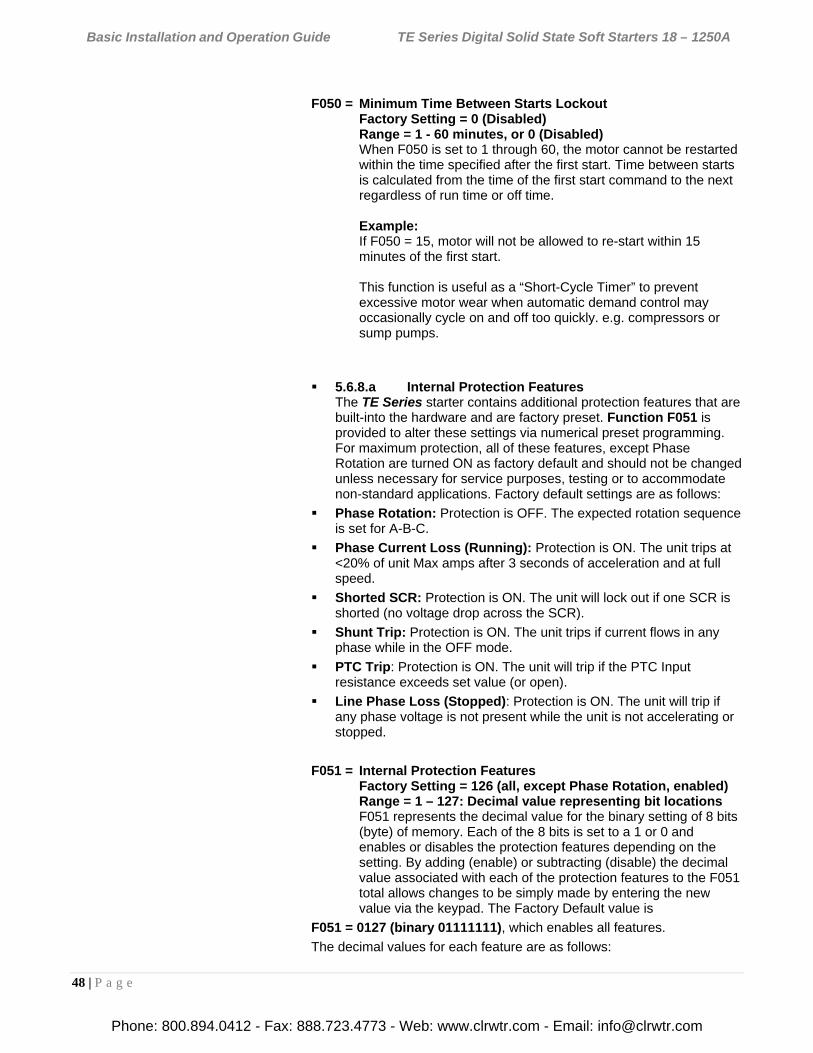
Basic Installation and Operation Guide TE Series Digital Solid State Soft Starters 18 – 1250A
48 | P a g e
F050 = Minimum Time Between Starts Lockout Factory Setting = 0 (Disabled) Range = 1 - 60 minutes, or 0 (Disabled) When F050 is set to 1 through 60, the motor cannot be restarted within the time specified after the first start. Time between starts is calculated from the time of the first start command to the next regardless of run time or off time. Example: If F050 = 15, motor will not be allowed to re-start within 15 minutes of the first start. This function is useful as a “Short-Cycle Timer” to prevent excessive motor wear when automatic demand control may occasionally cycle on and off too quickly. e.g. compressors or sump pumps.
5.6.8.a Internal Protection Features The TE Series starter contains additional protection features that are built-into the hardware and are factory preset. Function F051 is provided to alter these settings via numerical preset programming. For maximum protection, all of these features, except Phase Rotation are turned ON as factory default and should not be changed unless necessary for service purposes, testing or to accommodate non-standard applications. Factory default settings are as follows:
Phase Rotation: Protection is OFF. The expected rotation sequence is set for A-B-C.
Phase Current Loss (Running): Protection is ON. The unit trips at <20% of unit Max amps after 3 seconds of acceleration and at full speed.
Shorted SCR: Protection is ON. The unit will lock out if one SCR is shorted (no voltage drop across the SCR).
Shunt Trip: Protection is ON. The unit trips if current flows in any phase while in the OFF mode.
PTC Trip: Protection is ON. The unit will trip if the PTC Input resistance exceeds set value (or open).
Line Phase Loss (Stopped): Protection is ON. The unit will trip if any phase voltage is not present while the unit is not accelerating or stopped.
F051 = Internal Protection Features Factory Setting = 126 (all, except Phase Rotation, enabled) Range = 1 – 127: Decimal value representing bit locations F051 represents the decimal value for the binary setting of 8 bits (byte) of memory. Each of the 8 bits is set to a 1 or 0 and enables or disables the protection features depending on the setting. By adding (enable) or subtracting (disable) the decimal value associated with each of the protection features to the F051 total allows changes to be simply made by entering the new value via the keypad. The Factory Default value is
F051 = 0127 (binary 01111111), which enables all features.
The decimal values for each feature are as follows:
Phone: 800.894.0412 - Fax: 888.723.4773 - Web: www.clrwtr.com - Email: [email protected]
Basic Installation and Operation Guide TE Series Digital Solid State Soft Starters 18 – 1250A
49 | P a g e
Phase Rotation Protection: The TE Series is set up to monitor an expected phase rotation and will trip if this changes. Control of this feature is divided into two categories: On-Off and Expected Sequence. The default setting is On, with an Expected Sequence of A-B-C. The ability to turn this feature ON or OFF is useful in applications where the TE Series starter is going to be used downstream from an existing reversing contactor / starter, or to avoid conflicts with other protection devices.
Rotation Trip On-Off Control
Decimal value = 1 (b 00000001) If this feature is On (default setting) and you want to turn it Off, Subtract 1 from F051. If this feature is Off and you want to turn it On, add 1 to F051.When set to On, a trip will occur when the Expected Sequence (see below) is incorrect.
On large motors where large multiple cables are used, it may be easier to change the Expected Sequence in the TE Series starter rather than to swap the cables.
Expected Phase Rotation Sequence
Decimal Value = 2 (b 00000010) The A-B-C rotation is the default setting. To change to A-C-B, subtract 2 from F051. To change from A-C-B rotation to A-B-C, add 2 to F051. If the Rotation Trip is set to Off (see above), this setting is ignored.
Phase Current Loss (Running) Protection: This feature will cause a Trip if the current in any phase (or all 3) is less than 12% of the CT value after 3 seconds from a Start Command. (Note that this is based on the Max Amp rating and not the programmed FLA). Turn it OFF if the motor no-load current is exceptionally low such as in high inertia machines, or if you are testing a large starter with a small motor.
Phase Loss (Running) Protection
Decimal Value = 4 (b 00000100) This feature is On (default setting).To turn it Off, Subtract 4 from F051. If this feature is Off and you want to turn it On, add 4 to F051.
Shorted SCR Lockout protection: This feature will cause a Lockout if at least one SCR is shorted, based on the expected voltage drop across the SCR assembly when the unit is OFF. (Note- A shorted SCR cannot be detected while the unit is running or in Bypass mode). If qualified personnel knowing the ramifications of having a shorted SCR issue requires an emergency restart, this feature can be turned to OFF. This is not the same as a Shunt Trip circuit (see below). This is a lockout of the NEXT start command.
Shorted SCR Lockout
Decimal Value = 8 (b 00001000) This feature is On (default setting).To turn it Off, Subtract 8 from F051. If this feature is Off and you want to turn it On, add 8 to F051
Phone: 800.894.0412 - Fax: 888.723.4773 - Web: www.clrwtr.com - Email: [email protected]
Basic Installation and Operation Guide TE Series Digital Solid State Soft Starters 18 – 1250A
50 | P a g e
Shunt Trip: Shunt Trip is a feature that will cause an immediate Trip if the TE Series detects current flowing through any phase (or all) while the TE is in the Off state. The trip function is typically associated with the Aux. Relay setting 7 (see F060-63), wired to a Shunt Trip coil in an upstream circuit breaker or an in-line contactor. This function is to interrupt power flow to the motor windings in order to prevent damage. The usual cause is multiple shorted SCRs or a welded Bypass Contactor. The only time this function should be turned off is for troubleshooting by qualified service personnel.
Shunt Trip
Decimal Value = 16 (b 00010000) This feature is On (default setting).To turn it Off, Subtract 16 from F051. To turn it On, add 16 to F051.
PTC Trip: This feature controls the inclusion of the PTC Input (see Section 4.2.7). When it is ON (default setting), a jumper wire or other circuit must be installed on the PTC input if a PTC resistor is not included in the motor. Turn this feature to OFF for troubleshooting or if a jumper wire is not used.
PTC Trip
Decimal Value = 32 (b 00100000) This feature is On (default setting). To turn it Off, Subtract 32 from F051.To turn it On, add 32 to F051.
Line Phase Loss (Stopped) Trip: This feature will prevent the TE Series starter from attempting to start if the voltage in one (or more) of the incoming phases is not present. This can be used to detect a blown fuse or power supply loss provided control power is still available. It differs from the Phase Loss (Running) Trip in that it is based upon line voltage and does not require that a Start Command be given. This trip function resets itself after determining that all 3 phases have voltage applied. The voltage level at which this feature activates is fixed at approximately 100VAC.It is not adjustable and should not be used as Under Voltage protection.
Line Phase Loss (Stopped) Trip
Decimal Value = 64 (b 01000000) This feature is On (default setting).To turn it Off, Subtract 64 from F051.To turn it On, add 64 to F051.
Notes: 1) When using an In-Line Isolation Contactor, it may be necessary to turn Off this protection (by subtracting a numeric value of 64 from F051) in order to avoid nuisance tripping whenever the In-Line Contactor opens. 2) This protection will automatically reset itself when line voltage is present on all 3 phases. When using 3-wire control, the TE Series will not attempt to restart unless the Start Command is re-initiated.
Caution: When using 2-wire control, the starter will restart when this feature resets itself after all 3 phases are present.
Phone: 800.894.0412 - Fax: 888.723.4773 - Web: www.clrwtr.com - Email: [email protected]
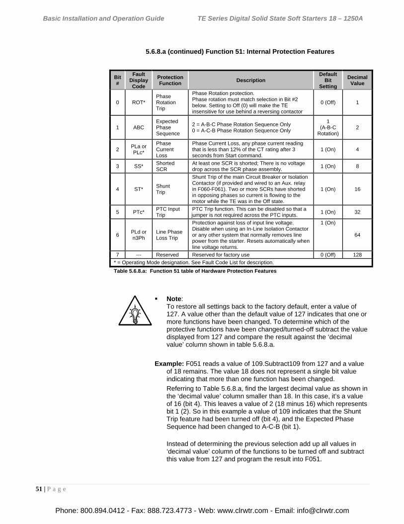
Basic Installation and Operation Guide TE Series Digital Solid State Soft Starters 18 – 1250A
51 | P a g e
5.6.8.a (continued) Function 51: Internal Protection Features
Note: To restore all settings back to the factory default, enter a value of 127. A value other than the default value of 127 indicates that one or more functions have been changed. To determine which of the protective functions have been changed/turned-off subtract the value displayed from 127 and compare the result against the ‘decimal value’ column shown in table 5.6.8.a.
Example: F051 reads a value of 109.Subtract109 from 127 and a value of 18 remains. The value 18 does not represent a single bit value indicating that more than one function has been changed.
Referring to Table 5.6.8.a, find the largest decimal value as shown in the ‘decimal value’ column smaller than 18. In this case, it’s a value of 16 (bit 4). This leaves a value of 2 (18 minus 16) which represents bit 1 (2). So in this example a value of 109 indicates that the Shunt Trip feature had been turned off (bit 4), and the Expected Phase Sequence had been changed to A-C-B (bit 1).
Instead of determining the previous selection add up all values in ‘decimal value’ column of the functions to be turned off and subtract this value from 127 and program the result into F051.
Bit #
Fault Display Code
Protection Function
Description Default
Bit Setting
Decimal Value
0 ROT* Phase Rotation Trip
Phase Rotation protection. Phase rotation must match selection in Bit #2 below. Setting to Off (0) will make the TE insensitive for use behind a reversing contactor
0 (Off) 1
1 ABC Expected Phase Sequence
2 = A-B-C Phase Rotation Sequence Only 0 = A-C-B Phase Rotation Sequence Only
1 (A-B-C
Rotation) 2
2 PLa or PLc*
Phase Current Loss
Phase Current Loss, any phase current reading that is less than 12% of the CT rating after 3 seconds from Start command.
1 (On) 4
3 SS* Shorted SCR
At least one SCR is shorted; There is no voltage drop across the SCR phase assembly.
1 (On) 8
4 ST* Shunt Trip
Shunt Trip of the main Circuit Breaker or Isolation Contactor (if provided and wired to an Aux. relay in F060-F061). Two or more SCRs have shorted in opposing phases so current is flowing to the motor while the TE was in the Off state.
1 (On) 16
5 PTc* PTC Input Trip
PTC Trip function. This can be disabled so that a jumper is not required across the PTC inputs.
1 (On) 32
6 PLd or n3Ph
Line Phase Loss Trip
Protection against loss of input line voltage. Disable when using an In-Line Isolation Contactor or any other system that normally removes line power from the starter. Resets automatically when line voltage returns.
1 (On)
64
7 --- Reserved Reserved for factory use 0 (Off) 128
* = Operating Mode designation. See Fault Code List for description.
Table 5.6.8.a: Function 51 table of Hardware Protection Features
Phone: 800.894.0412 - Fax: 888.723.4773 - Web: www.clrwtr.com - Email: [email protected]
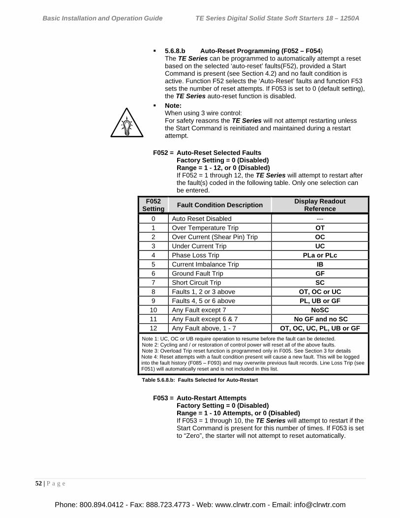
Basic Installation and Operation Guide TE Series Digital Solid State Soft Starters 18 – 1250A
52 | P a g e
5.6.8.b Auto-Reset Programming (F052 – F054) The TE Series can be programmed to automatically attempt a reset based on the selected ‘auto-reset’ faults(F52), provided a Start Command is present (see Section 4.2) and no fault condition is active. Function F52 selects the ‘Auto-Reset’ faults and function F53 sets the number of reset attempts. If F053 is set to 0 (default setting), the TE Series auto-reset function is disabled.
Note: When using 3 wire control: For safety reasons the TE Series will not attempt restarting unless the Start Command is reinitiated and maintained during a restart attempt.
F052 = Auto-Reset Selected Faults Factory Setting = 0 (Disabled) Range = 1 - 12, or 0 (Disabled) If F052 = 1 through 12, the TE Series will attempt to restart after the fault(s) coded in the following table. Only one selection can be entered.
F052 Setting
Fault Condition Description Display Readout
Reference
0 Auto Reset Disabled --- 1 Over Temperature Trip OT 2 Over Current (Shear Pin) Trip OC 3 Under Current Trip UC 4 Phase Loss Trip PLa or PLc 5 Current Imbalance Trip IB 6 Ground Fault Trip GF 7 Short Circuit Trip SC 8 Faults 1, 2 or 3 above OT, OC or UC 9 Faults 4, 5 or 6 above PL, UB or GF 10 Any Fault except 7 NoSC 11 Any Fault except 6 & 7 No GF and no SC 12 Any Fault above, 1 - 7 OT, OC, UC, PL, UB or GF
Note 1: UC, OC or UB require operation to resume before the fault can be detected. Note 2: Cycling and / or restoration of control power will reset all of the above faults. Note 3: Overload Trip reset function is programmed only in F005. See Section 3 for details Note 4: Reset attempts with a fault condition present will cause a new fault. This will be logged into the fault history (F085 – F093) and may overwrite previous fault records. Line Loss Trip (see F051) will automatically reset and is not included in this list.
Table 5.6.8.b: Faults Selected for Auto-Restart
F053 = Auto-Restart Attempts Factory Setting = 0 (Disabled) Range = 1 - 10 Attempts, or 0 (Disabled) If F053 = 1 through 10, the TE Series will attempt to restart if the Start Command is present for this number of times. If F053 is set to “Zero”, the starter will not attempt to reset automatically.
Phone: 800.894.0412 - Fax: 888.723.4773 - Web: www.clrwtr.com - Email: [email protected]
Basic Installation and Operation Guide TE Series Digital Solid State Soft Starters 18 – 1250A
53 | P a g e
5.6.8.c Timer Value Readouts for Protection Features F054 – F059 provide display of timer or register values for information only. The user cannot alter them. Upon power loss and restoration, these values are updated for time elapsed.
F054 = Restart Delay Time Readout Factory Setting = Not Applicable Range = 1 - 999 Seconds Remaining time value readout of F028, the Auto-Restart Delay Timer.
F055 = Coast Down (Backspin) Timer Value Factory Setting = Not Applicable Range = 1 - 3600 Seconds Remaining time value readout of F048, the Coast Down Lockout Timer.
F056 = Starts per Hour Timer Value Factory Setting = Not Applicable Range = 1 - 3600 Seconds Remaining time value readout of F049, the Starts-per-Hour Lockout Timer.
F057 = Starts per Hour Counter Readout Factory Setting = Not Applicable Range = 1 - 10 Starts Incremental counter value readout of F050, the Starts-per-Hour Lockout.
F058 = Time Value Between Starts Readout Factory Setting = Not Applicable Range = 1 - 3600 Seconds Remaining time value readout of F050, the Minimum Time Between Starts Timer.
F059 = Thermal Capacity to Start Readout Factory Setting = Not Applicable Range = 0 - 100 % Thermal Capacity Readout only for the user’s viewing of the motor Thermal Capacity percentage required to allow a Reset after an Overload Trip. Use this function in conjunction with the Remaining Thermal Capacity (in the Status Screen group) to be able to predict when a restart will be allowed. This value is automatically updated by the TE Series CPU whenever a successful start sequence has been accomplished. The TE Series essentially “learns” how much Thermal Capacity is needed in the motor in order to successfully restart, and stores the information in this Function. Upon power loss and restoration, this value is updated for elapsed time.
Phone: 800.894.0412 - Fax: 888.723.4773 - Web: www.clrwtr.com - Email: [email protected]
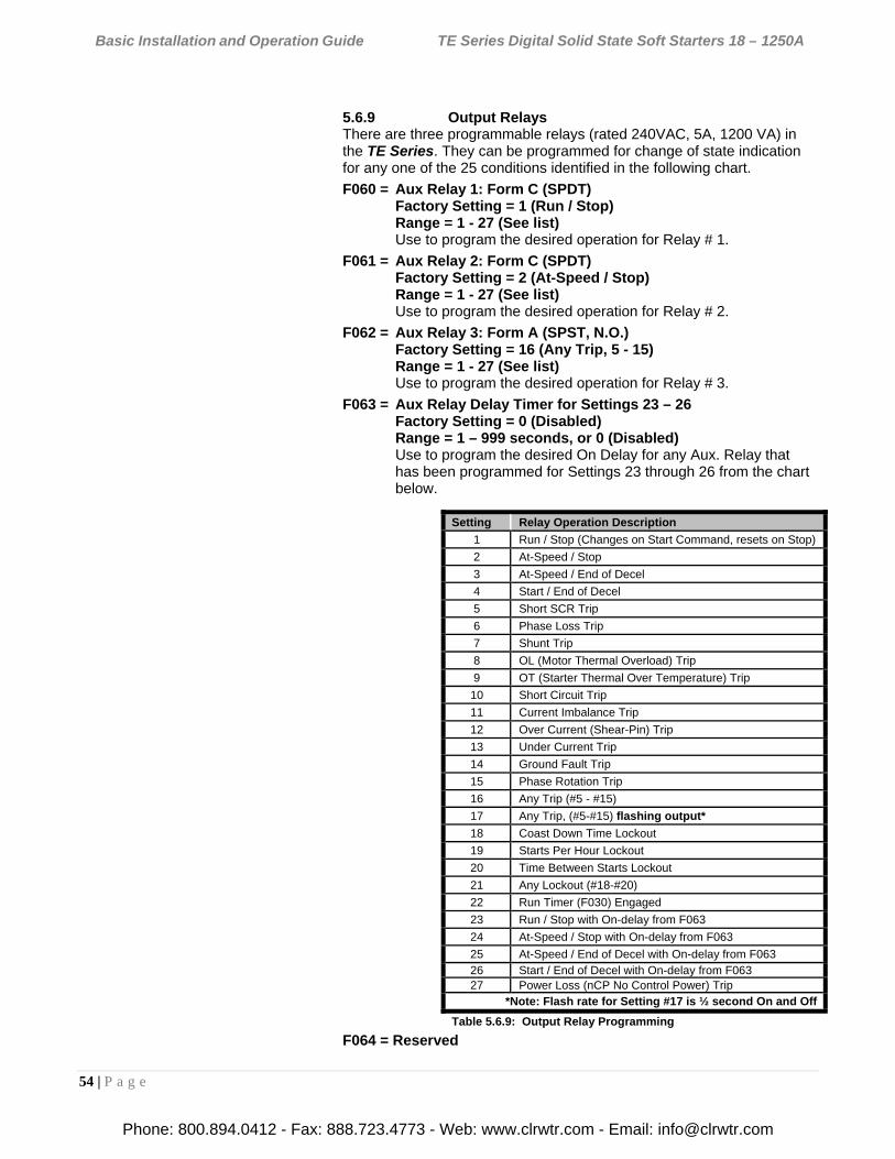
Basic Installation and Operation Guide TE Series Digital Solid State Soft Starters 18 – 1250A
54 | P a g e
5.6.9 Output Relays There are three programmable relays (rated 240VAC, 5A, 1200 VA) in the TE Series. They can be programmed for change of state indication for any one of the 25 conditions identified in the following chart.
F060 = Aux Relay 1: Form C (SPDT) Factory Setting = 1 (Run / Stop) Range = 1 - 27 (See list) Use to program the desired operation for Relay # 1.
F061 = Aux Relay 2: Form C (SPDT) Factory Setting = 2 (At-Speed / Stop) Range = 1 - 27 (See list) Use to program the desired operation for Relay # 2.
F062 = Aux Relay 3: Form A (SPST, N.O.) Factory Setting = 16 (Any Trip, 5 - 15) Range = 1 - 27 (See list) Use to program the desired operation for Relay # 3.
F063 = Aux Relay Delay Timer for Settings 23 – 26 Factory Setting = 0 (Disabled) Range = 1 – 999 seconds, or 0 (Disabled) Use to program the desired On Delay for any Aux. Relay that has been programmed for Settings 23 through 26 from the chart below.
F064 = Reserved
Setting Relay Operation Description
1 Run / Stop (Changes on Start Command, resets on Stop)
2 At-Speed / Stop
3 At-Speed / End of Decel
4 Start / End of Decel
5 Short SCR Trip
6 Phase Loss Trip
7 Shunt Trip
8 OL (Motor Thermal Overload) Trip
9 OT (Starter Thermal Over Temperature) Trip
10 Short Circuit Trip
11 Current Imbalance Trip
12 Over Current (Shear-Pin) Trip
13 Under Current Trip
14 Ground Fault Trip
15 Phase Rotation Trip
16 Any Trip (#5 - #15)
17 Any Trip, (#5-#15) flashing output*
18 Coast Down Time Lockout
19 Starts Per Hour Lockout
20 Time Between Starts Lockout
21 Any Lockout (#18-#20)
22 Run Timer (F030) Engaged
23 Run / Stop with On-delay from F063
24 At-Speed / Stop with On-delay from F063
25 At-Speed / End of Decel with On-delay from F063 26 Start / End of Decel with On-delay from F063 27 Power Loss (nCP No Control Power) Trip
*Note: Flash rate for Setting #17 is ½ second On and Off
Table 5.6.9: Output Relay Programming
Phone: 800.894.0412 - Fax: 888.723.4773 - Web: www.clrwtr.com - Email: [email protected]
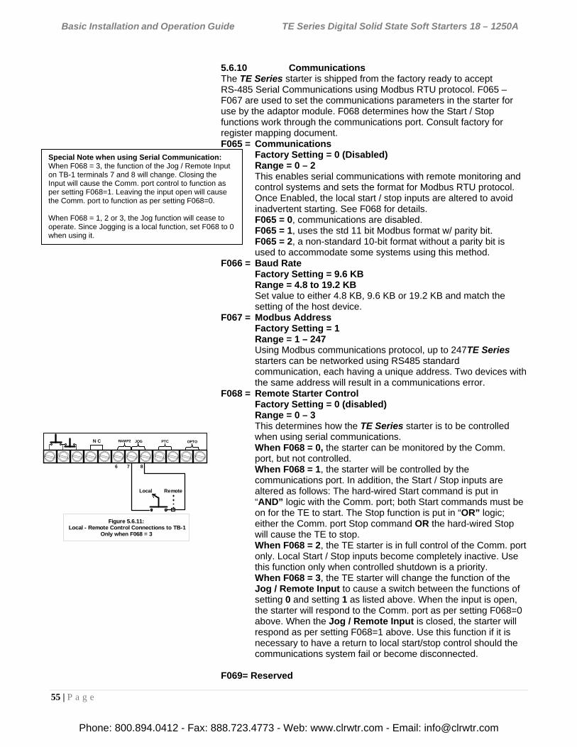
Basic Installation and Operation Guide TE Series Digital Solid State Soft Starters 18 – 1250A
55 | P a g e
5.6.10 Communications The TE Series starter is shipped from the factory ready to accept RS-485 Serial Communications using Modbus RTU protocol. F065 – F067 are used to set the communications parameters in the starter for use by the adaptor module. F068 determines how the Start / Stop functions work through the communications port. Consult factory for register mapping document. F065 = Communications
Factory Setting = 0 (Disabled) Range = 0 – 2 This enables serial communications with remote monitoring and control systems and sets the format for Modbus RTU protocol. Once Enabled, the local start / stop inputs are altered to avoid inadvertent starting. See F068 for details. F065 = 0, communications are disabled. F065 = 1, uses the std 11 bit Modbus format w/ parity bit. F065 = 2, a non-standard 10-bit format without a parity bit is used to accommodate some systems using this method.
F066 = Baud Rate Factory Setting = 9.6 KB Range = 4.8 to 19.2 KB Set value to either 4.8 KB, 9.6 KB or 19.2 KB and match the setting of the host device.
F067 = Modbus Address Factory Setting = 1 Range = 1 – 247 Using Modbus communications protocol, up to 247TE Series starters can be networked using RS485 standard communication, each having a unique address. Two devices with the same address will result in a communications error.
F068 = Remote Starter Control Factory Setting = 0 (disabled) Range = 0 – 3 This determines how the TE Series starter is to be controlled when using serial communications. When F068 = 0, the starter can be monitored by the Comm. port, but not controlled. When F068 = 1, the starter will be controlled by the communications port. In addition, the Start / Stop inputs are altered as follows: The hard-wired Start command is put in “AND” logic with the Comm. port; both Start commands must be on for the TE to start. The Stop function is put in “OR” logic; either the Comm. port Stop command OR the hard-wired Stop will cause the TE to stop. When F068 = 2, the TE starter is in full control of the Comm. port only. Local Start / Stop inputs become completely inactive. Use this function only when controlled shutdown is a priority. When F068 = 3, the TE starter will change the function of the Jog / Remote Input to cause a switch between the functions of setting 0 and setting 1 as listed above. When the input is open, the starter will respond to the Comm. port as per setting F068=0 above. When the Jog / Remote Input is closed, the starter will respond as per setting F068=1 above. Use this function if it is necessary to have a return to local start/stop control should the communications system fail or become disconnected.
F069= Reserved
N C JOGRAMP2 PTC OPTO
Figure 5.6.11: Local - Remote Control Connections to TB-1
Only when F068 = 3
Local Remote
6 7 8
Special Note when using Serial Communication: When F068 = 3, the function of the Jog / Remote Input on TB-1 terminals 7 and 8 will change. Closing the Input will cause the Comm. port control to function as per setting F068=1. Leaving the input open will cause the Comm. port to function as per setting F068=0. When F068 = 1, 2 or 3, the Jog function will cease to operate. Since Jogging is a local function, set F068 to 0 when using it.
Phone: 800.894.0412 - Fax: 888.723.4773 - Web: www.clrwtr.com - Email: [email protected]
Basic Installation and Operation Guide TE Series Digital Solid State Soft Starters 18 – 1250A
56 | P a g e
5.6.11 System Settings The following functions set operator interface controls and unit programming. Also contained here are the Clock settings used for history functions. Change the Clock settings if accurate time values are important. F070 = Parameter Lock / User Password
Factory Setting = 0 (disabled) Range = 0 – 999 Use only when necessary to prevent unauthorized access. This provides users with the ability to prevent unauthorized operators from making changes to the programmed functions. If you do NOT need to take advantage of this feature, do not enter anything into this function. The factory default is disabled, and no Password is necessary to make changes to the program.
See Appendix 3 at the end of this manual for detailed instructions on using and altering the Parameter Lock / User Password feature.
F071 = Emergency Clear / Reset Factory Setting = 0 (disabled) Range = 0 – 2 This Function serves two purposes. It can clear the memory values used for lockouts and overload protection, and it can reset all functions to the factory default settings. This is a “One-Shot” feature, so when another value is entered as shown below, this function automatically returns to the default state.
When F071 = 0, the feature is disabled.
When F071 = 1, the values stored in the Thermal Register and all of the Lockout Timers will be cleared. This will allow an Emergency Restart without having to wait for proper cool down time or lockout timers to expire.
WARNING!
Clearing the Thermal Register to allow restarting without proper cool-down time after an Overload Trip can result in motor damage and fire. Use only where emergency restart is necessary with knowledge of these potential hazards.
When F071 = 2, the values of all functions will be reset to the factory default settings. Use this feature when setting conflicts have occurred or parameters have been tampered with. The Fault History is also cleared with this function.
Note: This will not reset F070 = Parameter Lock / User Password. See Appendix 3 for resetting this feature. F072 = Reserved
Phone: 800.894.0412 - Fax: 888.723.4773 - Web: www.clrwtr.com - Email: [email protected]
Basic Installation and Operation Guide TE Series Digital Solid State Soft Starters 18 – 1250A
57 | P a g e
F073 = Unit Frame Rating: Read Only. Reserved for Factory Use
F074 = CT Ratio: Read Only. This is the primary value of the TE Series internal Current Transformers (CTs) for use in determining the GF trip settings (F046). CTs cannot be used for external metering. Alteration is reserved for factory use only.
5.6.11.a Real Time Clock Settings Functions F075 through F080 set the system real time clock. The time clock is used for date/time stamping of the Fault History. The clock automatically adjusts for leap years and is backed up by a Lithium ion battery for long life.
Note: The time clock does not automatically adjust for daylight savings time.
F075= Year Factory Setting = Year of manufacture Range = 2000 to 2047
F076 = Month Factory Setting = Month of manufacture Range = 1 – 12
F077 = Day Factory Setting = Day of manufacture Range = 1 – 31
F078 = Hour Factory Setting = Actual (EST) Range = 0 - 23 (12:00 midnight is hour 0)
F079 = Minute Factory Setting = Actual (EST) Range = 0 – 59
F080 = Second Factory Setting = Actual (EST) Range = 0 – 59
F081 = Firmware revision number for Factory Use
F082 -F084 = Reserved
Phone: 800.894.0412 - Fax: 888.723.4773 - Web: www.clrwtr.com - Email: [email protected]
Basic Installation and Operation Guide TE Series Digital Solid State Soft Starters 18 – 1250A
58 | P a g e
5.6.12 Fault History and Statistical Data
F085 – F097 contain the Fault History and Statistical data for the Run Mode.
5.6.12.a Fault History Fault codes for each of the three latest events are stored with time and date stamps; see Chapter 7 for a complete list of fault codes and corresponding error displays. Time stamps use the 24hr HH.MM format, so for example 3:19 PM would display as [15.19] Date stamps use the MM.DD format, so for example September 3rd would display [09.03]
Fault #1
(Latest Fault) Fault #2
(Previous Fault) Fault #3
(Oldest Fault) Fault code:
(See Chapter 7) F085 F088 F091
Time Stamp (HH.mm)
F086 F089 F092
Date Stamp (MM.DD)
F087 F090 F093
Table 5.6.12.a: Fault History Configuration
F085 = Latest Fault Code (Fault #1) Factory Setting = 0 (No Fault) Range = 0 – 27 This Function displays the Fault Code of the latest fault event.
F086 = Time Stamp of the Latest Fault Factory Setting = 00.00 (No Fault) Range = 00.00 – 23.59 (24hr time format) This Function displays the time of the latest fault event.
F087 = Date Stamp of the Latest Fault Factory Setting = 00.00 (No Fault) Range = 01.01 – 12.31 This Function displays the date of the latest fault event.
F088 = Same as F085 except for the Previous Fault (Fault #2)
F089 = Same as F086 except for the Previous Fault.
F090 = Same as F087 except for the Previous Fault.
F091 = Same as F085 except for the Oldest Fault (Fault #3)
F092 = Same as F086 except for the Oldest Fault
F093 = Same as F087 except for the Oldest Fault
Phone: 800.894.0412 - Fax: 888.723.4773 - Web: www.clrwtr.com - Email: [email protected]
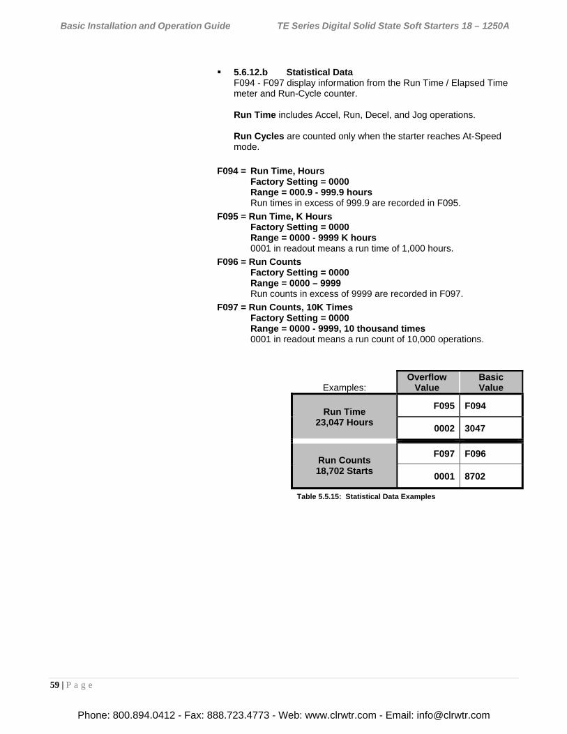
Basic Installation and Operation Guide TE Series Digital Solid State Soft Starters 18 – 1250A
59 | P a g e
5.6.12.b Statistical Data F094 - F097 display information from the Run Time / Elapsed Time meter and Run-Cycle counter. Run Time includes Accel, Run, Decel, and Jog operations. Run Cycles are counted only when the starter reaches At-Speed mode.
F094 = Run Time, Hours Factory Setting = 0000 Range = 000.9 - 999.9 hours Run times in excess of 999.9 are recorded in F095.
F095 = Run Time, K Hours Factory Setting = 0000 Range = 0000 - 9999 K hours 0001 in readout means a run time of 1,000 hours.
F096 = Run Counts Factory Setting = 0000 Range = 0000 – 9999 Run counts in excess of 9999 are recorded in F097.
F097 = Run Counts, 10K Times Factory Setting = 0000 Range = 0000 - 9999, 10 thousand times 0001 in readout means a run count of 10,000 operations.
Examples: Overflow
Value Basic Value
Run Time 23,047 Hours
F095 F094
0002 3047
Run Counts 18,702 Starts
F097 F096
0001 8702
Table 5.5.15: Statistical Data Examples
Phone: 800.894.0412 - Fax: 888.723.4773 - Web: www.clrwtr.com - Email: [email protected]
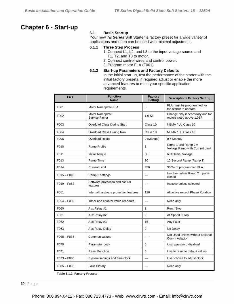
Basic Installation and Operation Guide TE Series Digital Solid State Soft Starters 18 – 1250A
60 | P a g e
Chapter 6 - Start-up
6.1 Basic Startup Your new TE Series Soft Starter is factory preset for a wide variety of applications and often can be used with minimal adjustment.
6.1.1 Three Step Process 1. Connect L1, L2, and L3 to the input voltage source and T1, T2, and T3 to motor. 2. Connect control wires and control power. 3. Program motor FLA (F001).
6.1.2 Start-up Parameters and Factory Defaults In the initial start-up, test the performance of the starter with the initial factory presets, if required adjust or enable the more advanced features to meet your specific application requirements.
Fn # Function Name
Factory Setting
Description / Factory Setting
F001 Motor Nameplate FLA. 0 FLA must be programmed for the starter to operate.
F002 Motor Nameplate Service Factor
1.0 SF Change only if necessary and for motors rated above 1.0SF
F003 Overload Class During Start Class 10 NEMA / UL Class 10
F004 Overload Class During Run Class 10 NEMA / UL Class 10
F005 Overload Reset 0 (Manual) 0 = Manual
F010 Ramp Profile 1 Ramp 1 and Ramp 2 = Voltage Ramp with Current Limit
F011 Initial Torque 60 60% Initial Voltage
F013 Ramp Time 10 10 Second Ramp (Ramp 1)
F014 Current Limit 350 350% of programmed FLA
F015 – F018 Ramp 2 settings --- Inactive unless Ramp 2 Input is closed
F019 – F052 Software protection and control features
--- Inactive unless selected
F051 Internal hardware protection features 126 All active except Phase Rotation
F054 – F059 Timer and counter value readouts --- Read only
F060 Aux Relay #1 1 Run / Stop
F061 Aux Relay #2 2 At-Speed / Stop
F062 Aux Relay #3 16 Any Fault
F063 Aux Relay Delay 0 No Delay
F065 – F068 Communications ---- Not Used unless without optional Comm Adaptor.
F070 Parameter Lock 0 User password disabled
F071 Reset Function 0 Use to reset to default values
F073 – F080 System settings and time clock --- User choice to adjust clock
F085 – F093 Fault History --- Read only
Table 6.1.2: Factory Presets
Phone: 800.894.0412 - Fax: 888.723.4773 - Web: www.clrwtr.com - Email: [email protected]
Basic Installation and Operation Guide TE Series Digital Solid State Soft Starters 18 – 1250A
61 | P a g e
6.2 Start-up Check List
� Supply voltage matches the rated supply voltage of the unit.
� Horsepower and current ratings of the motor and starter have the same rating or the starter has a higher rating.
� Initial ramp time and torque adjustments have been checked.
� Input voltage source are connected to the starters input terminals L1, L2 and L3.
� Motor leads are connected to the starter output terminals T1, T2, and T3.
� Appropriate control power is applied and/or control connections have been made.
� “Power On” light located on the front of the unit turns on when control power is applied.
� The four 7-segment LED readout is visible.
� The motor’s FLA has been programmed in function F001.
� The thermal overload is properly set. (Use F003 and F004 to set OL Class.)
� The motor area and equipment are clear of personnel and parts before start-up.
6.3 Sequence of Operation
Apply three-phase power to the unit. The motor should not run until the start command is applied.
Apply control power and check that the “Power On” LED comes on.
Status Display should read [0000.] showing no current in Phase A (minor flickering of the first digit is common).
Apply the Run (Start) command. The motor should begin to accelerate. Status display will read Phase A Amps at an increasing rate.
When the motor reaches full speed, the “At-Speed” LED comes on. Status display should show a sharp decrease in Phase-A amps.
The Bypass Contactor should pull in.
If the motor does not fully accelerate, decelerates, or stops during the acceleration period, push the Stop button immediately and open the disconnect line.
If Pump-Flex Decel is programmed in F025:
Remove the Run Command (or push the Stop button). At-Speed LED will go out.
The Bypass Contactor should drop out.
Status display should read Phase-A amps increasing as motor begins to decelerate.
Motor should begin to slow down. Status display should begin to show decreasing motor amps.
When motor reaches Stop Level, starter should turn off. Status display will again show [0000.]
If the unit does not follow this operational sequence please refer to the Service and Troubleshooting Guide section.
Phone: 800.894.0412 - Fax: 888.723.4773 - Web: www.clrwtr.com - Email: [email protected]
Basic Installation and Operation Guide TE Series Digital Solid State Soft Starters 18 – 1250A
62 | P a g e
6.4 Testing with a smaller motor
To test the TE Series starter in combination with a motor that draws less than 20% of the starters Max Amp rating, the Phase Current Loss (Running) protection must be disabled as per instructions in section 5.6.8.a. If this feature is not disabled, the TE Series will trip on a Phase Loss fault after running for 3 seconds at low current levels. If disabled, it is recommended that Current Imbalance is enabled.
Chapter 7 - Fault Conditions
7.1 Fault Codes and Numbers (in History) A three-character fault code is displayed in the LED display at the time of the trip event. The first two digits indicate the trip condition (see Table 7.1). The third digit is a suffix showing the TE Series operating mode when the trip occurred. Operating modes are as follows: Code suffix “A”: Acceleration, meaning that the TE Series was ramping up but had not yet achieved “At-Speed” status (see section 4.2.9.b for a brief description of At-Speed indication). Code suffix “c”: Constant Speed (running), meaning that the TE Series has reached the At-Speed condition and the motor was running when the trip occurred.
Code suffix “d”: Decel or Stop, meaning that TE Series was either stopped (off, but power applied), or if the Pump-Flex Decel function was enabled, it was engaged in the Soft Stop routine set up by F024-27.
IMPORTANT NOTE: Fault code SSd may display if there is no output load (motor) connection when control power is applied!
In addition to these fault display codes, each trip condition has a corresponding numeric code that is stored in the Fault History (see section 5.6.12.a). The numeric codes follow the display codes exactly. Table 7.1 shows the Fault Display Codes, Fault Number Codes and LED indicators for each fault condition. Additional details are available in the Service and Troubleshooting Guide. Example: If Function F003 (starting overload protection) is set too low for the size of the load and causes a trip, the fault code “oLA” will be displayed. Its corresponding number will be entered into the fault history. In this case, the number 0010 will be shown on the display in function F085 (Fault History). The time the fault occurred is available in function F086 shown as “hh.mm.”Example: if the “oLA” fault occurred at 10:00 am, F086 would display “10.00.” The date the fault occurred is available in function F087. The date is shown as “mm.dd”. If the “oLA” fault occurred on March 1, F077 shows“03.01.” If no fault history is available F085 reads 0000.
Phone: 800.894.0412 - Fax: 888.723.4773 - Web: www.clrwtr.com - Email: [email protected]
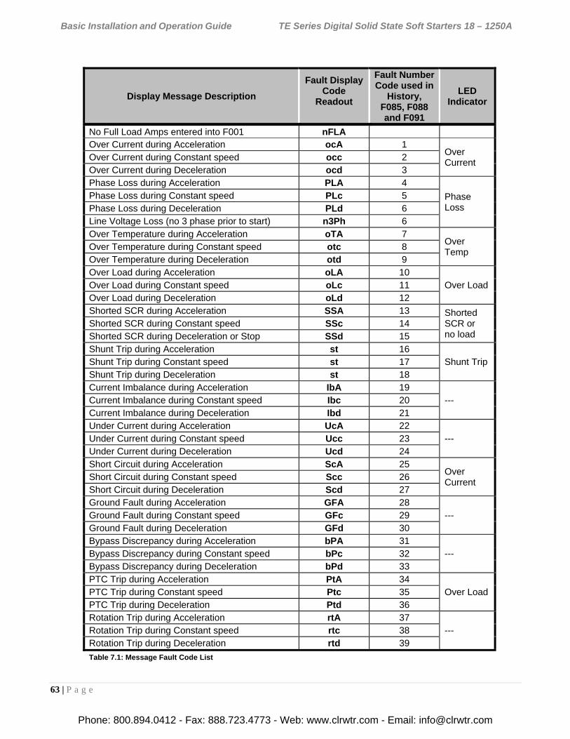
Basic Installation and Operation Guide TE Series Digital Solid State Soft Starters 18 – 1250A
63 | P a g e
Display Message Description
Fault Display Code
Readout
Fault Number Code used in
History, F085, F088 and F091
LED Indicator
No Full Load Amps entered into F001 nFLA Over Current during Acceleration ocA 1
Over Current
Over Current during Constant speed occ 2 Over Current during Deceleration ocd 3 Phase Loss during Acceleration PLA 4
Phase Loss
Phase Loss during Constant speed PLc 5 Phase Loss during Deceleration PLd 6 Line Voltage Loss (no 3 phase prior to start) n3Ph 6 Over Temperature during Acceleration oTA 7
Over Temp
Over Temperature during Constant speed otc 8 Over Temperature during Deceleration otd 9 Over Load during Acceleration oLA 10
Over Load Over Load during Constant speed oLc 11 Over Load during Deceleration oLd 12 Shorted SCR during Acceleration SSA 13 Shorted
SCR or no load
Shorted SCR during Constant speed SSc 14 Shorted SCR during Deceleration or Stop SSd 15 Shunt Trip during Acceleration st 16
Shunt Trip Shunt Trip during Constant speed st 17 Shunt Trip during Deceleration st 18 Current Imbalance during Acceleration IbA 19
--- Current Imbalance during Constant speed Ibc 20 Current Imbalance during Deceleration Ibd 21 Under Current during Acceleration UcA 22
--- Under Current during Constant speed Ucc 23 Under Current during Deceleration Ucd 24 Short Circuit during Acceleration ScA 25
Over Current
Short Circuit during Constant speed Scc 26 Short Circuit during Deceleration Scd 27 Ground Fault during Acceleration GFA 28
--- Ground Fault during Constant speed GFc 29 Ground Fault during Deceleration GFd 30 Bypass Discrepancy during Acceleration bPA 31
--- Bypass Discrepancy during Constant speed bPc 32 Bypass Discrepancy during Deceleration bPd 33 PTC Trip during Acceleration PtA 34
Over Load PTC Trip during Constant speed Ptc 35 PTC Trip during Deceleration Ptd 36 Rotation Trip during Acceleration rtA 37 Rotation Trip during Constant speed rtc 38 --- Rotation Trip during Deceleration rtd 39
Table 7.1: Message Fault Code List
Phone: 800.894.0412 - Fax: 888.723.4773 - Web: www.clrwtr.com - Email: [email protected]
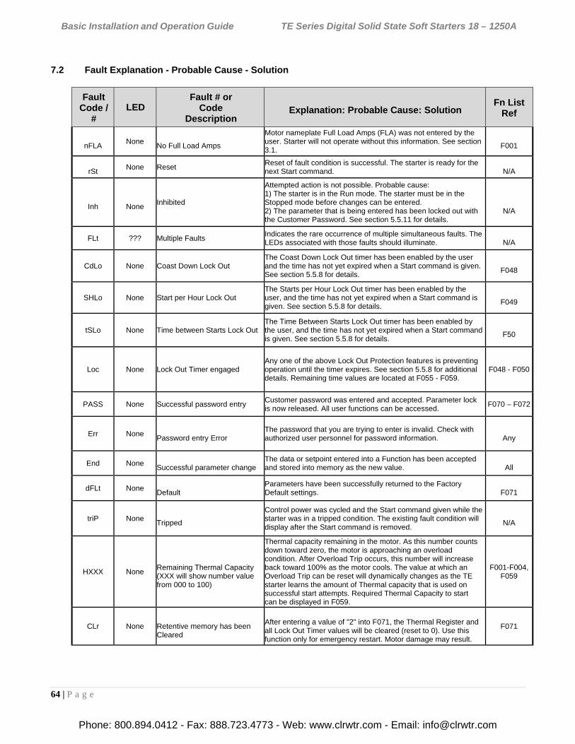
Basic Installation and Operation Guide TE Series Digital Solid State Soft Starters 18 – 1250A
64 | P a g e
7.2 Fault Explanation - Probable Cause - Solution
Fault Code /
# LED
Fault # or Code
Description
Explanation: Probable Cause: Solution
Fn List Ref
nFLA
None No Full Load Amps
Motor nameplate Full Load Amps (FLA) was not entered by the user. Starter will not operate without this information. See section 3.1.
F001
rSt
None Reset Reset of fault condition is successful. The starter is ready for the next Start command.
N/A
Inh
None
Inhibited
Attempted action is not possible. Probable cause: 1) The starter is in the Run mode. The starter must be in the Stopped mode before changes can be entered. 2) The parameter that is being entered has been locked out with the Customer Password. See section 5.5.11 for details.
N/A
FLt ??? Multiple Faults Indicates the rare occurrence of multiple simultaneous faults. The LEDs associated with those faults should illuminate.
N/A
CdLo None Coast Down Lock Out The Coast Down Lock Out timer has been enabled by the user and the time has not yet expired when a Start command is given. See section 5.5.8 for details.
F048
SHLo None Start per Hour Lock Out The Starts per Hour Lock Out timer has been enabled by the user, and the time has not yet expired when a Start command is given. See section 5.5.8 for details.
F049
tSLo None Time between Starts Lock Out The Time Between Starts Lock Out timer has been enabled by the user, and the time has not yet expired when a Start command is given. See section 5.5.8 for details.
F50
Loc None Lock Out Timer engaged Any one of the above Lock Out Protection features is preventing operation until the timer expires. See section 5.5.8 for additional details. Remaining time values are located at F055 - F059.
F048 - F050
PASS None Successful password entry Customer password was entered and accepted. Parameter lock is now released. All user functions can be accessed.
F070 – F072
Err None Password entry Error
The password that you are trying to enter is invalid. Check with authorized user personnel for password information.
Any
End None Successful parameter change
The data or setpoint entered into a Function has been accepted and stored into memory as the new value.
All
dFLt None Default
Parameters have been successfully returned to the Factory Default settings.
F071
triP None Tripped
Control power was cycled and the Start command given while the starter was in a tripped condition. The existing fault condition will display after the Start command is removed.
N/A
HXXX None
Remaining Thermal Capacity (XXX will show number value from 000 to 100)
Thermal capacity remaining in the motor. As this number counts down toward zero, the motor is approaching an overload condition. After Overload Trip occurs, this number will increase back toward 100% as the motor cools. The value at which an Overload Trip can be reset will dynamically changes as the TE starter learns the amount of Thermal capacity that is used on successful start attempts. Required Thermal Capacity to start can be displayed in F059.
F001-F004, F059
CLr None Retentive memory has been Cleared
After entering a value of "2" into F071, the Thermal Register and all Lock Out Timer values will be cleared (reset to 0). Use this function only for emergency restart. Motor damage may result.
F071
Phone: 800.894.0412 - Fax: 888.723.4773 - Web: www.clrwtr.com - Email: [email protected]
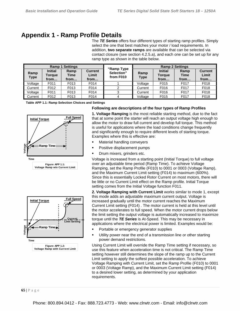
Basic Installation and Operation Guide TE Series Digital Solid State Soft Starters 18 – 1250A
65 | P a g e
Appendix 1 - Ramp Profile Details
The TE Series offers four different types of starting ramp profiles. Simply select the one that best matches your motor / load requirements. In addition, two separate ramps are available that can be selected via contact closure (see section 4.2.5.a), and each one can be set up for any ramp type as shown in the table below.
Following are descriptions of the four types of Ramp Profiles
1. Voltage Ramping is the most reliable starting method, due to the fact that at some point the starter will reach an output voltage high enough to allow the motor to draw full current and develop full torque. This method is useful for applications where the load conditions change frequently and significantly enough to require different levels of starting torque. Examples where this is effective are:
Material handling conveyers
Positive displacement pumps
Drum mixers, grinders etc.
Voltage is increased from a starting point (Initial Torque) to full voltage over an adjustable time period (Ramp Time). To achieve Voltage Ramping, set the Ramp Profile (F010) to 0001 or 0003 (Voltage Ramp), and the Maximum Current Limit setting (F014) to maximum (600%). Since this is essentially Locked Rotor Current on most motors, there will be little or no Current Limit effect on the Ramp profile. Initial Torque setting comes from the Initial Voltage function F011.
2. Voltage Ramping with Current Limit works similar to mode 1, except this mode adds an adjustable maximum current output. Voltage is increased gradually until the motor current reaches the Maximum Current Limit setting (F014) . The motor current is held at this level until the motor accelerates to full speed. When the motor current drops below the limit setting the output voltage is automatically increased to maximize torque until the TE Series is At-Speed. This may be necessary in applications where the electrical power is limited. Examples would be:
Portable or emergency generator supplies
Utility power near the end of a transmission line or other starting power demand restrictions.
Using Current Limit will override the Ramp Time setting if necessary, so use this feature when acceleration time is not critical. The Ramp Time setting however still determines the slope of the ramp up to the Current Limit setting to apply the softest possible acceleration. To achieve Voltage Ramping with Current Limit, set the Ramp Profile (F010) to 0001 or 0003 (Voltage Ramp), and the Maximum Current Limit setting (F014) to a desired lower setting, as determined by your application requirements.
Ramp 1 Settings “Ramp Type Selection” from F010
Ramp 2 Settings
Ramp Type
Initial Torque from…
Ramp Time
from…
Current Limit
from…
Ramp Type
Initial Torque from…
Ramp Time
from…
Current Limit
from… Voltage F011 F013 F014 1 Voltage F015 F017 F018 Current F012 F013 F014 2 Current F016 F017 F018 Voltage F011 F013 F014 3 Current F016 F017 F018 Current F012 F013 F014 4 Voltage F015 F017 F018
Table APP 1.1: Ramp Selection Choices and Settings
Initial Torque Full Speed
Vo
lta
ge
Time
Figure APP 1.2:Voltage Ramp with Current Limit
Ramp Time
CurrentLimit Setting
Initial Torque Full Speed
Vo
lta
ge
Time
Figure APP 1.1:Voltage Ramp w/o Current Limit
Ramp Time
Phone: 800.894.0412 - Fax: 888.723.4773 - Web: www.clrwtr.com - Email: [email protected]
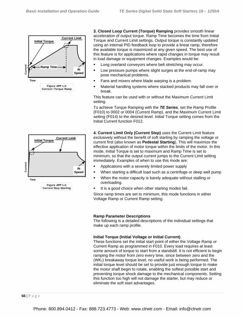
Basic Installation and Operation Guide TE Series Digital Solid State Soft Starters 18 – 1250A
66 | P a g e
3. Closed Loop Current (Torque) Ramping provides smooth linear acceleration of output torque. Ramp Time becomes the time from Initial Torque and Current Limit settings. Output torque is constantly updated using an internal PID feedback loop to provide a linear ramp, therefore the available torque is maximized at any given speed. The best use of this feature is for applications where rapid changes in torque may result in load damage or equipment changes. Examples would be:
Long overland conveyors where belt stretching may occur.
Low pressure pumps where slight surges at the end-of-ramp may pose mechanical problems.
Fans and mixers where blade warping is a problem.
Material handling systems where stacked products may fall over or break.
This feature can be used with or without the Maximum Current Limit setting.
To achieve Torque Ramping with the TE Series, set the Ramp Profile (F010) to 0002 or 0004 (Current Ramp), and the Maximum Current Limit setting (F014) to the desired level. Initial Torque setting comes from the Initial Current function F012.
4. Current Limit Only (Current Step) uses the Current Limit feature exclusively without the benefit of soft starting by ramping the voltage or current first (also known as Pedestal Starting). This will maximize the effective application of motor torque within the limits of the motor. In this mode, Initial Torque is set to maximum and Ramp Time is set to minimum, so that the output current jumps to the Current Limit setting immediately. Examples of when to use this mode are:
Applications with a severely limited power supply
When starting a difficult load such as a centrifuge or deep well pump
When the motor capacity is barely adequate without stalling or overloading.
It is a good choice when other starting modes fail.
Since ramp times are set to minimum, this mode functions in either Voltage Ramp or Current Ramp setting.
Ramp Parameter Descriptions The following is a detailed descriptions of the individual settings that make up each ramp profile.
Initial Torque (Initial Voltage or Initial Current). These functions set the initial start point of either the Voltage Ramp or Current Ramp as programmed in F010. Every load requires at least some amount of torque to start from a standstill. It is not efficient to begin ramping the motor from zero every time, since between zero and the (WK2) breakaway torque level, no useful work is being performed. The initial torque level should be set to provide just enough torque to make the motor shaft begin to rotate, enabling the softest possible start and preventing torque shock damage to the mechanical components. Setting this function too high will not damage the starter, but may reduce or eliminate the soft start advantages.
Initial TorqueCurrent Limit
Cu
rre
nt
Time
Figure APP 1.3:Current / Torque Ramp
Ramp TimeAt
Speed
Initial TorqueCurrent Limit
Cu
rre
nt
Time
Figure APP 1.4:Current Step Starting
AtSpeed
Phone: 800.894.0412 - Fax: 888.723.4773 - Web: www.clrwtr.com - Email: [email protected]
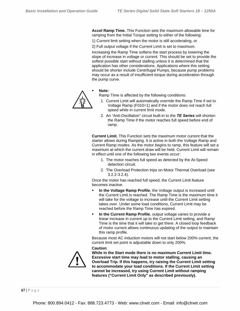
Basic Installation and Operation Guide TE Series Digital Solid State Soft Starters 18 – 1250A
67 | P a g e
Accel Ramp Time. This Function sets the maximum allowable time for ramping from the Initial Torque setting to either of the following:
1) Current limit setting when the motor is still accelerating, or
2) Full output voltage if the Current Limit is set to maximum.
Increasing the Ramp Time softens the start process by lowering the slope of increase in voltage or current. This should be set to provide the softest possible start without stalling unless it is determined that the application has other considerations. Applications where this setting should be shorter include Centrifugal Pumps, because pump problems may occur as a result of insufficient torque during acceleration through the pump curve.
Note: Ramp Time is affected by the following conditions:
1. Current Limit will automatically override the Ramp Time if set to Voltage Ramp (F010=1) and if the motor does not reach full speed while in current limit mode.
2. An “Anti-Oscillation” circuit built-in to the TE Series will shorten the Ramp Time if the motor reaches full speed before end of ramp.
Current Limit. This Function sets the maximum motor current that the starter allows during Ramping. It is active in both the Voltage Ramp and Current Ramp modes. As the motor begins to ramp, this feature will set a maximum at which the current draw will be held. Current Limit will remain in effect until one of the following two events occur:
1. The motor reaches full speed as detected by the At-Speed detection circuit.
2. The Overload Protection trips on Motor Thermal Overload (see 3.2.2-3.2.4).
Once the motor has reached full speed, the Current Limit feature becomes inactive.
In the Voltage Ramp Profile, the Voltage output is increased until the Current Limit is reached. The Ramp Time is the maximum time it will take for the voltage to increase until the Current Limit setting takes over. Under some load conditions, Current Limit may be reached before the Ramp Time has expired.
In the Current Ramp Profile, output voltage varies to provide a linear increase in current up to the Current Limit setting, and Ramp Time is the time that it will take to get there. A closed loop feedback of motor current allows continuous updating of the output to maintain this ramp profile.
Because most AC induction motors will not start below 200% current, the current limit set point is adjustable down to only 200%.
Caution: While in the Start mode there is no maximum Current Limit time. Excessive start time may lead to motor stalling, causing an Overload Trip. If this happens, try raising the Current Limit setting to accommodate your load conditions. If the Current Limit setting cannot be increased, try using Current Limit without ramping features (“Current Limit Only” as described previously).
Phone: 800.894.0412 - Fax: 888.723.4773 - Web: www.clrwtr.com - Email: [email protected]
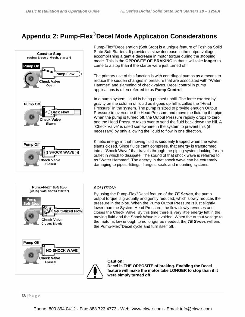
Basic Installation and Operation Guide TE Series Digital Solid State Soft Starters 18 – 1250A
68 | P a g e
Appendix 2: Pump-FlexDecel Mode Application Considerations
Pump-FlexDeceleration (Soft Stop) is a unique feature of Toshiba Solid State Soft Starters. It provides a slow decrease in the output voltage, accomplishing a gentle decrease in motor torque during the stopping mode. This is the OPPOSITE OF BRAKING in that it will take longer to come to a stop than if the starter were just turned off.
The primary use of this function is with centrifugal pumps as a means to reduce the sudden changes in pressure that are associated with “Water Hammer” and slamming of check valves. Decel control in pump applications is often referred to as Pump Control. In a pump system, liquid is being pushed uphill. The force exerted by gravity on the column of liquid as it goes up hill is called the “Head Pressure” in the system. The pump is sized to provide enough Output Pressure to overcome the Head Pressure and move the fluid up the pipe. When the pump is turned off, the Output Pressure rapidly drops to zero and the Head Pressure takes over to send the fluid back down the hill. A “Check Valve” is used somewhere in the system to prevent this (if necessary) by only allowing the liquid to flow in one direction.
Kinetic energy in that moving fluid is suddenly trapped when the valve slams closed. Since fluids can’t compress, that energy is transformed into a “Shock Wave” that travels through the piping system looking for an outlet in which to dissipate. The sound of that shock wave is referred to as “Water Hammer”. The energy in that shock wave can be extremely damaging to pipes, fittings, flanges, seals and mounting systems.
SOLUTION:
By using the Pump-FlexDecel feature of the TE Series, the pump output torque is gradually and gently reduced, which slowly reduces the pressure in the pipe. When the Pump Output Pressure is just slightly lower than the System Head Pressure, the flow slowly reverses and closes the Check Valve. By this time there is very little energy left in the moving fluid and the Shock Wave is avoided. When the output voltage to the motor is low enough to no longer be needed, the TE Series will end the Pump-FlexDecel cycle and turn itself off.
Caution! Decel is THE OPPOSITE of braking. Enabling the Decel feature will make the motor take LONGER to stop than if it were simply turned off.
Pump On
Check ValveOpen
Pump Off
Check ValveSlams
PumpSoft Stop
Check ValveCloses Slowly
Neutralized Flow
Pump Off
Check ValveClosed
((( SHOCK WAVE )))
Coast-to-Stop(using Electro-Mech. starter)
Pump-Flex Soft Stop(using VMX Series starter)
Pump Off
Check ValveClosed
NO SHOCK WAVE
Pump Flow
Back Flow
Phone: 800.894.0412 - Fax: 888.723.4773 - Web: www.clrwtr.com - Email: [email protected]
Basic Installation and Operation Guide TE Series Digital Solid State Soft Starters 18 – 1250A
69 | P a g e
Setup and Use Pump systems vary greatly. To accommodate this, the Pump-FlexDecel control feature is designed to provide complete flexibility in how the deceleration process takes place by using the following settings. Decel begins when a Stop command is given (or the Run command is removed). If there is a Bypass Contactor, it will open immediately, putting the power control back to the SCRs.
Figure APP2.2: Pump-Flex Decel Graph
F024 = Deceleration Ramp Factory Setting = 0 (Disabled) Range = 0 – 2
When F024 = 0, the deceleration feature is disabled.
When F024 = 1, the deceleration feature is enabled AND the overload protection feature (from F003 - F005) remains active. When a Stop command is given, the starter begins to apply Decel voltage. However, if an overload trip occurs, the starter ceases applying Decel voltage and the motor coasts to a stop to prevent additional motor heating and potential motor damage.
When F024 = 2, the deceleration feature is enabled and deceleration will continue even when an overload condition trips. This is to be used only when the risk of damage due to an uncontrolled shutdown is considered worse than the potential damage to the motor.
WARNING!
Setting F025 = 2 presents significant risk of over-heating the motor beyond its design limits which could result in motor damage and fire hazard. Do this only in circumstances where the potential for mechanical damage outweighs the risk of motor damage and fire.
Note: The PTC Input will act as an Overload trip (disable), however it ALWAYS shuts the starter down WITHOUT Decel (as in setting F025=1 above) even if F025 is set to 2 if PTC input opens.
Stop Command(Bypass Contactor Opens)
F025 : Begin Decel Level(Immediate step down)
F026: Decel Shut Off (TE Output Off)
Voltage
Time
F027 : Decel Ramp Time
Full Speed Check ValveCloses
= Motor Torque
= Pump Output
Phone: 800.894.0412 - Fax: 888.723.4773 - Web: www.clrwtr.com - Email: [email protected]
Basic Installation and Operation Guide TE Series Digital Solid State Soft Starters 18 – 1250A
70 | P a g e
F025 = Begin Decel Level (BDL) Factory Setting = 60% Range = 0 - 100% of line voltage Used to drop voltage to a level where there is a noticeable effect on motor torque during Decel mode. Generally, systems with high head pressure need to start Decel near the top of the ramp (85-95%). Low head systems can drop to lower settings (50-60%). System conditions vary greatly by pump type, pipe size and system head. Some experimentation with settings may be necessary.
F026 = Decel Shut Off Voltage Factory Setting = 30% Range = 0 to (BDL -1)% Sets the level where the starter is turned off, corresponding to where motor torque during Decel is no longer effective. Always set this function lower than the setting of F026, Begin Decel Level (this function is restricted from being less than F026 minus 1%). This function is used to shut the motor off once the check valve closes. Again, because systems vary greatly this setting may require adjustment several times. If you cannot hear or see the check valve close, observe fluid pressure or flow if available.
F027 = Decel Ramp Time Factory Setting = 10 seconds Range = 1 - 60 seconds Sets the maximum time for the deceleration ramp to go from the Begin Decel Level setting (F026) to the Decel Shut Off Voltage (F027). This function is used to dampen the effect of reducing pump torque as much as possible. If the check valve still slams at the end of ramp, try extending this time function a little. Since motor heating increases as voltage is lowered, the setting should not exceed the time necessary to achieve the deceleration effect.
Note: When using the Decel function, count these cycles as additional “starts” when determining maximum starts-per-hour.
Other Applications: Another common application for Decel control is on material handling conveyors as a means to prevent sudden stops that may cause products to shift, fall over or to bump into one another.
In overhead crane applications, Soft Stopping of the Bridge or Trolley can prevent loads from beginning to over swing on sudden stops.
Phone: 800.894.0412 - Fax: 888.723.4773 - Web: www.clrwtr.com - Email: [email protected]
Basic Installation and Operation Guide TE Series Digital Solid State Soft Starters 18 – 1250A
71 | P a g e
Appendix 3: Parameter Lock / User Password Instructions
Users are provided with the ability to prevent unauthorized operators from making changes to the programmed functions. If you do not need to take advantage of this feature, do not enter anything into this function. The factory default is disabled, and no Password is necessary to make changes to the program.
When any value other than 0000 is entered into this Function F070, the Parameter Lock is enabled and that number becomes the User Password. From that point forward, it will be necessary to enter the User Password in this Function prior to making changes in any programmed function, including this one. When the Parameter Lock has been enabled, attempts to alter the program will result in the display reading [Err ] whenever the [READ/ENTER] key is pressed.
To alter the program after the Parameter Lock has been enabled, go to Function F070 and enter the correct user Password. The display will read an encoded value representing the existing password. As soon as you press the first Arrow key, the display will change to [0000] and start showing the actual value of your password entry. When the [READ/ ENTER] button is pressed, the display will read [PASS], indicating that the User Password is correct and the system is unlocked. You will have 5 minutes in which to make a change in the program. This 5-minute window resets whenever any key is pressed, so it floats to give you 5 minutes after the last entry. After 5 minutes of no keypad activity, the Parameter Lock is reinstated with the current user Password. Subsequent changes will require re-entering the User Password.
To change the User Password or to disable the Parameter Lock function, enter the programmed User Password first, and then set Function F070 to 0, disabling the Parameter Lock. If you do not re-enter the Password or enter a new user password, the Parameter Lock feature will remain disabled. If you enter a different number into this Function, the new number becomes your new User Password. Existing passwords are encoded to “hide” them in the display.
Caution: DO NOT LOSE YOUR PASSWORD. If the password has been lost or forgotten, contact Toshiba for assistance.
Phone: 800.894.0412 - Fax: 888.723.4773 - Web: www.clrwtr.com - Email: [email protected]
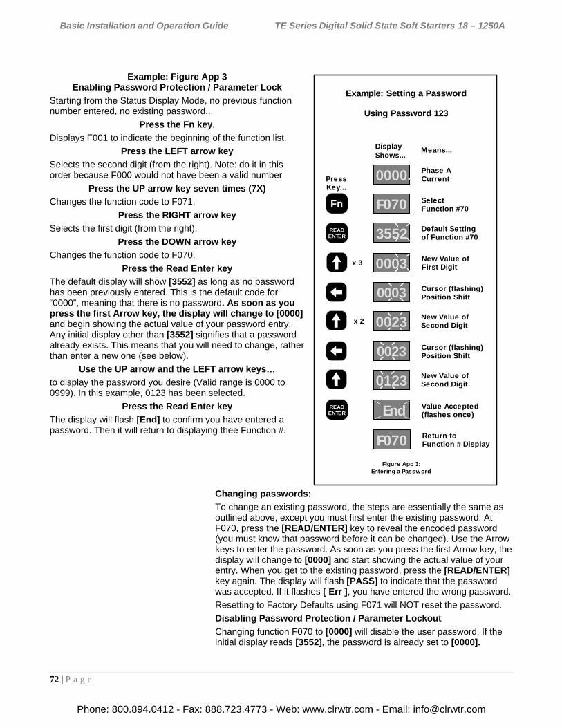
Basic Installation and Operation Guide TE Series Digital Solid State Soft Starters 18 – 1250A
72 | P a g e
Display
PressKey...
Shows...Means...
Phase ACurrent
SelectFunction #70
Default Settingof Function #70
New Value ofFirst Digit
Cursor (flashing)Position Shift
New Value ofSecond Digit
0000.
F070
3552
0003
0003
0023
End Value Accepted(flashes once)
Return toFunction # Display
Figure App 3:Entering a Password
Example: Setting a Password
Using Password 123
F070
READENTER
Fn
READENTER
x 3
x 2
Cursor (flashing)Position Shift
New Value ofSecond Digit
0023
0123
Example: Figure App 3 Enabling Password Protection / Parameter Lock
Starting from the Status Display Mode, no previous function number entered, no existing password...
Press the Fn key.
Displays F001 to indicate the beginning of the function list.
Press the LEFT arrow key
Selects the second digit (from the right). Note: do it in this order because F000 would not have been a valid number
Press the UP arrow key seven times (7X)
Changes the function code to F071.
Press the RIGHT arrow key
Selects the first digit (from the right).
Press the DOWN arrow key
Changes the function code to F070.
Press the Read Enter key
The default display will show [3552] as long as no password has been previously entered. This is the default code for “0000”, meaning that there is no password. As soon as you press the first Arrow key, the display will change to [0000] and begin showing the actual value of your password entry. Any initial display other than [3552] signifies that a password already exists. This means that you will need to change, rather than enter a new one (see below).
Use the UP arrow and the LEFT arrow keys…
to display the password you desire (Valid range is 0000 to 0999). In this example, 0123 has been selected.
Press the Read Enter key
The display will flash [End] to confirm you have entered a password. Then it will return to displaying thee Function #.
Changing passwords:
To change an existing password, the steps are essentially the same as outlined above, except you must first enter the existing password. At F070, press the [READ/ENTER] key to reveal the encoded password (you must know that password before it can be changed). Use the Arrow keys to enter the password. As soon as you press the first Arrow key, the display will change to [0000] and start showing the actual value of your entry. When you get to the existing password, press the [READ/ENTER] key again. The display will flash [PASS] to indicate that the password was accepted. If it flashes [ Err ], you have entered the wrong password.
Resetting to Factory Defaults using F071 will NOT reset the password.
Disabling Password Protection / Parameter Lockout
Changing function F070 to [0000] will disable the user password. If the initial display reads [3552], the password is already set to [0000]. 2
Ramp 0mofile
Phone: 800.894.0412 - Fax: 888.723.4773 - Web: www.clrwtr.com - Email: [email protected]
Basic Installation and Operation Guide TE Series Digital Solid State Soft Starters 18 – 1250A
73 | P a g e
Appendix 4 – External Overload Relay Applications
Your TE Series starter comes equipped with a very intelligent internal electronic overload protection system, and does not need an external Overload Relay (OLR). There are instances however where external OLRs are needed or desired because of the application. These fall into three categories; Higher Level Protection systems, Redundant Backup applications and Special Motor applications. Note:
If the Decel Function is activated (F024), additional consideration must be put into determining how the starter is to operate in the event of an Overload Trip. See Section 5.6.5 for issues regarding this application.
HIGHER LEVEL PROTECTION SYSTEMS Because of a desire for uniformity and/or operator familiarity in some facilities, Motor Protection Relays or other coordinated OEM protection systems may be used in lieu of the TE Series protection (even though most of the features are the same or better). In these instances the TE Series Over Load protection can simply be turned off, deferring protection to the external devices. Care should be taken however to ensure that the external device is properly wired into the starter control circuit to facilitate shutdown of the motor. The TE Series provides a PTC input that can be wired to the NC aux contact of the external device so that a fault will still shut down the TE Series and be annunciated on the display. See section 4.7.2.a for more details on using the PTC input.
REDUNDANT BYPASS STARTER APPLICATIONS: In some applications, it may be necessary to provide an independent means of starting and protecting the motor should be TE Series starter become inoperable. If this were the case, the Bypass Contactor could be used for Across-the-Line (D.O.L) starting of the motor. The TE…BP version with Integral Bypass Contactors is designed for that possibility, as long as the starter is properly selected when ordered. To do so, select the starter based upon the ATL (Across-the-Line) selection chart so that the contactor is rated for ATL duty instead of the normal Shunt Duty (see section 1.2.3 for Selection charts). Under normal operations, the Bypass Contactor is controlled internally by the TE Series PC board and an internal pilot relay. For redundant backup purposes however, terminals B1 and B2 of TB4 are provided for field connection of a dry contact closure in parallel to the pilot relay contact, allowing control even if the electronics are out of service. AC control power must still be applied to TB2 terminals A1 and A2, but no other electronics or power supplies need to be functioning. It is in this instance that an external OLR must be added to the motor power circuit and wired into that coil control circuit. TB4 is located in different areas of each frame size in the TE Series. Refer to the following diagram for the location on your unit.
Phone: 800.894.0412 - Fax: 888.723.4773 - Web: www.clrwtr.com - Email: [email protected]
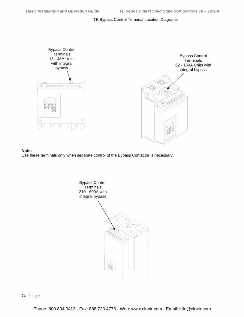
Basic Installation and Operation Guide TE Series Digital Solid State Soft Starters 18 – 1250A
74 | P a g e
TE Bypass Control Terminal Location Diagrams
Note: Use these terminals only when separate control of the Bypass Contactor is necessary.
Bypass Control Terminals
18 - 48A Units with integral
bypass
Bypass Control Terminals
62 - 160A Units with integral bypass
Bypass Control Terminals
210 - 600A with integral bypass
Phone: 800.894.0412 - Fax: 888.723.4773 - Web: www.clrwtr.com - Email: [email protected]
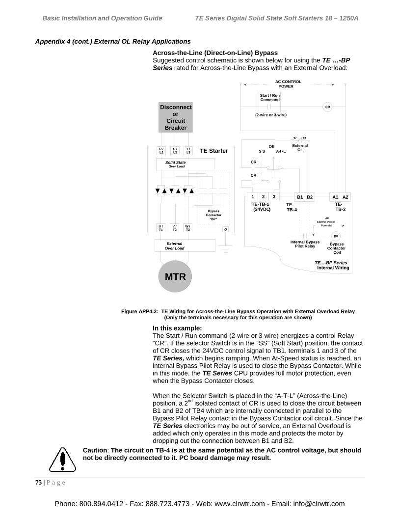
Basic Installation and Operation Guide TE Series Digital Solid State Soft Starters 18 – 1250A
75 | P a g e
Appendix 4 (cont.) External OL Relay Applications
Across-the-Line (Direct-on-Line) Bypass Suggested control schematic is shown below for using the TE …-BP Series rated for Across-the-Line Bypass with an External Overload:
Figure APP4.2: TE Wiring for Across-the-Line Bypass Operation with External Overload Relay (Only the terminals necessary for this operation are shown)
In this example: The Start / Run command (2-wire or 3-wire) energizes a control Relay “CR”. If the selector Switch is in the “SS” (Soft Start) position, the contact of CR closes the 24VDC control signal to TB1, terminals 1 and 3 of the TE Series, which begins ramping. When At-Speed status is reached, an internal Bypass Pilot Relay is used to close the Bypass Contactor. While in this mode, the TE Series CPU provides full motor protection, even when the Bypass Contactor closes. When the Selector Switch is placed in the “A-T-L” (Across-the-Line) position, a 2nd isolated contact of CR is used to close the circuit between B1 and B2 of TB4 which are internally connected in parallel to the Bypass Pilot Relay contact in the Bypass Contactor coil circuit. Since the TE Series electronics may be out of service, an External Overload is added which only operates in this mode and protects the motor by dropping out the connection between B1 and B2.
Caution: The circuit on TB-4 is at the same potential as the AC control voltage, but should not be directly connected to it. PC board damage may result.
B1 B2
Internal BypassPilot Relay
AC
Control Power
Potential
TE- TB-4
BP
(2-wire or 3-wire)
97 98
CR
TE Starter .
BypassContactor
"BP"
Disconnector
CircuitBreaker
.
.
MTR
G
R /L1
T /L3
S /L2
U /T1
W /T3
V /T2
OffS S A- T -L
Solid StateOver Load
ExternalOver Load
1 2 3 A1 A2
AC CONTROL POWER
Start / RunCommand
ExternalOL
TE...-BP SeriesInternal Wiring
TE-TB-1(24VDC)
TE-TB-2
BypassContactor
Coil
CR
CR
Phone: 800.894.0412 - Fax: 888.723.4773 - Web: www.clrwtr.com - Email: [email protected]
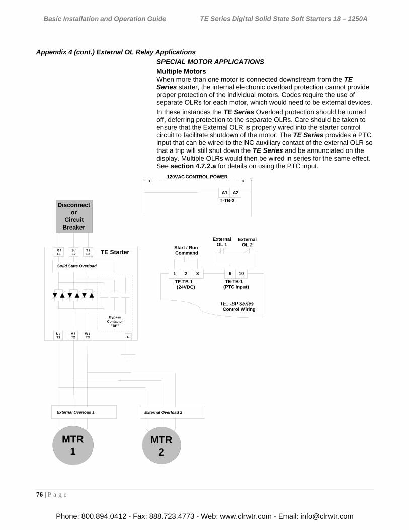
Basic Installation and Operation Guide TE Series Digital Solid State Soft Starters 18 – 1250A
76 | P a g e
Appendix 4 (cont.) External OL Relay Applications
SPECIAL MOTOR APPLICATIONS
Multiple Motors When more than one motor is connected downstream from the TE Series starter, the internal electronic overload protection cannot provide proper protection of the individual motors. Codes require the use of separate OLRs for each motor, which would need to be external devices.
In these instances the TE Series Overload protection should be turned off, deferring protection to the separate OLRs. Care should be taken to ensure that the External OLR is properly wired into the starter control circuit to facilitate shutdown of the motor. The TE Series provides a PTC input that can be wired to the NC auxiliary contact of the external OLR so that a trip will still shut down the TE Series and be annunciated on the display. Multiple OLRs would then be wired in series for the same effect. See section 4.7.2.a for details on using the PTC input.
1 2 3
A1 A2
120VAC CONTROL POWER
Start / RunCommand
TE...-BP SeriesControl Wiring
TE-TB-1(24VDC)
T-TB-2
MTR2
9 10
TE-TB-1(PTC Input)
ExternalOL 1
ExternalOL 2
External Overload 2
TE Starter .
BypassContactor
"BP"
Disconnector
CircuitBreaker
.
MTR1
G
R /L1
T /L3
S /L2
U /T1
W /T3
V /T2
External Overload 1
Solid State Overload
Phone: 800.894.0412 - Fax: 888.723.4773 - Web: www.clrwtr.com - Email: [email protected]
Basic Installation and Operation Guide TE Series Digital Solid State Soft Starters 18 – 1250A
77 | P a g e
Appendix 4 (cont.) External OL Relay Applications
SPECIAL MOTOR APPLICATIONS
2S-2W Motors 2 speed / 2 winding motor applications require a separate OLR sized for each set of windings. These would need to be external OLRs.
In this example: The TE Series is used ahead of an existing 2S2W starter, which already has separate OLRs for each speed. Dry Aux. contacts of the 2S2W starter are used to provide a Run command to the TE Series so that all existing controls can be used. In addition, another dry Aux. of the Fast contactor is used to select Ramp 2. When started in Slow, Ramp 1 (default) is used. If started in Fast, different ramp settings are necessary so Ramp 2 is used. (See section 4.2.5.a for Dual Ramp info.)
Either OLR will trip the TE Series, which will display [Ptc] and light the “Overload” LED.
TE Starter .
BypassContactor
"BP"
Disconnector
CircuitBreaker
.
.
G
R /L1
T /L3
S /L2
U /T1
W /T3
V /T2
1 2 3
A1 A2
120VAC CONTROL POWER
TE...-BP SeriesControl Wiring
TE-TB1(24VDC)
TE-TB-2
9 10
TE-TB1(PTC Input)
SlowOL
FastOL
2S2WMTR
MS MF
MS
MF
2S2W Starter (Logic not shown for clarity)
MS
MF
External 2-Speed 2-Winding (2S2W ) Starter
6 7
MF
TE-TB1 (Ramp 2 )
Solid State Overload
Slow Speed Overload Fast Speed Overload
Phone: 800.894.0412 - Fax: 888.723.4773 - Web: www.clrwtr.com - Email: [email protected]
Basic Installation and Operation Guide TE Series Digital Solid State Soft Starters 18 – 1250A
78 | P a g e
Appendix 5 - Soft Starter Settings Record The following chart may be used to record the changes made to the factory settings.
Fn # Group Function Description Adjustment / Display Range
Setting Increments
Factory Setting
Setting
F001
Mo
tor
an
d O
verl
oad
In
fo.
Motor Nameplate FLA FLA must be programmed for starter to function.
50-100% of Max Amp Rating. Upper limit of range automatically adjusts downward as Service factor is increased.
1 amp 0
F002 Motor Nameplate Service Factor
1.00 - 1.30 SF 0.05 1.0 SF
F003 Overload Class During Start NEMA / UL Class 5 - 20 5 Class 10
F004 Overload Class During Run NEMA / UL Class 5 - 30 5 Class 10
F005 Overload Reset 0 = Manual 1 = Auto 2 = Disabled Overload
1 0
(Manual)
F006-9 Reserved for factory use
F010
Sta
rtin
g a
nd
Sto
pp
ing
Mo
de
s
Ramp Type Selection VR = Voltage Ramp CR = Current PID Ramp 1 = Ramp 1, 2 = Ramp 2
Setting 1 = VR1 + VR2 Setting 2 = CR1 + CR2 Setting 3 = VR1 + CR2 Setting 4 = CR1 + VR2
1 1
VR1+VR2
F011 Initial Torque (VR) of Ramp 1 0-100% Line Voltage 1% 60%
F012 Initial Torque (CR) of Ramp 1 0-600% Motor Current 1% 200%
F013 Accel Ramp Time of Ramp 1 1-120 seconds 1 second 10
seconds
F014 Max Current Limit of Ramp 1 200 - 600% Motor Current 1% 350%
F015 Initial Torque (VR) of Ramp 2 0-100% Line Voltage 1% 60%
F016 Initial Torque (CR) of Ramp 2 0-600% Motor Current 1% 200%
F017 Accel Ramp Time of Ramp 2 1-120 seconds 1 second 10
seconds
F018 Max Current Limit of Ramp 2 200 - 600% Motor Current 1% 350%
F019
Jog
Mo
des
Voltage Jog 5 – 100% Line Voltage 1% 50%
F020 Time of Voltage Jog 1 – 20 Seconds 1 second 10
seconds
F021 Current Jog 100 – 500% Motor Current 1% 150%
F022
Kic
k M
od
e Kick Start Voltage
0 = Disabled, or 10 - 100% Line Voltage
1% 0
Disabled
F023 Kick Start Time 0.1 - 2 Seconds 0.1second 0.8 sec
Phone: 800.894.0412 - Fax: 888.723.4773 - Web: www.clrwtr.com - Email: [email protected]
Basic Installation and Operation Guide TE Series Digital Solid State Soft Starters 18 – 1250A
79 | P a g e
Appendix 5 (cont.) Soft Starter Settings Record
Fn # Group Function Description Adjustment / Display Range
Setting Increments
Factory Setting
Setting
F024
Pu
mp
Fle
x D
ecel
Mo
de
Pump Flex Control / Deceleration Ramp
0 = Disabled (coast to stop) 1 = Enabled, except after OL trip 2 = Enabled, continued Decel even
if there is an OL trip
1 0
Disabled
F025 Begin Decel Level (BDL), Immediate Drop Down Torque
0 - 100 % of Output Voltage 1% 60%
F026 Decel Shut Off Voltage 0 to (BDL minus 1)% Voltage 1% 30%
F027 Decel Ramp Time 1 – 60 Seconds 1 second 10
seconds
F028
Res
tart
Restart Delay Time (Sequential Start Delay)
0 = Disabled, or 1-999 seconds after a Power Loss (Status can be read in F054)
1 second 0
Disabled
F029 Reserved for Factory Use
Phone: 800.894.0412 - Fax: 888.723.4773 - Web: www.clrwtr.com - Email: [email protected]
Basic Installation and Operation Guide TE Series Digital Solid State Soft Starters 18 – 1250A
80 | P a g e
Appendix 5 (cont.) Soft Starter Settings Record
Fn # Group Function Description Adjustment / Display Range
Setting Increments
Factory Setting
Setting
F040
Cu
rren
t an
d G
rou
nd
Fa
ult
Pro
tect
ion
Current Imbalance Trip 0 = Disabled, or 5 - 30% imbalance
1% 0
Disabled
F041 Current Imbalance Trip Delay 1 - 20 seconds 1 second 2
seconds
F042 Over Current Trip 0 = Disabled, or 100 - 300% of motor FLA
1% 0
Disabled
F043 Over Current Trip Delay 1 - 20 seconds 1 second 1 second
F044 Under Current Trip 0 = Disabled, or 10 - 90% of motor FLA
1% 0
Disabled
F045 Under Current Trip Delay 1 - 60 seconds 1 second 2
seconds
F046 Ground Fault Trip 0 = Disabled, or 5 - 90% of CT ratio from Fn 74 1%
0 Disabled
F047 Ground Fault Trip Delay 1 - 60 seconds 1 second 2
seconds
F048
Lo
cko
uts
, Res
et
and
Inte
rnal
Pro
tec
tio
n
Coast Down (Back Spin) Lockout Timer
0 = Disabled, or 1 - 60 minutes 1 minute 0
Disabled
F049 Maximum Starts per Hour 0 = Disabled, or 1 – 10 starts 1 0
Disabled
F050 Minimum Time Between Starts
0 = Disabled, or 1 - 60 minutes 1 minute 0
Disabled
F051 Internal Protection Settings 1 – 127 See 5.6.8.a
1 126
F052 Auto Reset on Selected Faults
Fault Preferences 1 – 12 See 5.6.8.b Fault Reset Selection Table
1 4:
Phase Loss only
F053 Auto Reset Attempts 0 = Disabled, or 1-10 attempts 1 0
Disabled
F054 Restart Delay Time Value Readout (for F028)
0-999 Minutes 1 0
F055 Coast Down Timer Value for F048
1-3600 Seconds 1 0
F056 Starts Per Hour Timer Value for F049
1-3600 Seconds 1 0
F057 Starts Per Hour For F049
1-10 Starts 1 0
F058 Time Value Between Starts for F050
1-3600 Seconds 1 0
F059 Thermal Capacity to Start for F005
0-100 % Thermal Capacity 1 0
F060
Ou
tpu
t R
elay
s
Aux Relay 1 setting Operation # 1 – 27: see ”Aux. Relay Settings Chart”
1 1
F061 Aux Relay 2 setting Operation # 1 – 27: see ”Aux. Relay Settings Chart”
1 2
F062 Aux Relay 3 setting Operation # 1 – 27: see ”Aux. Relay Settings Chart”
1 16
F063 Aux. Relay Delay Timer (for Operations 22-26)
0 (Disabled), or 1-999 seconds 1 second 0
No Delay
F064 Reserved for factory use
Phone: 800.894.0412 - Fax: 888.723.4773 - Web: www.clrwtr.com - Email: [email protected]
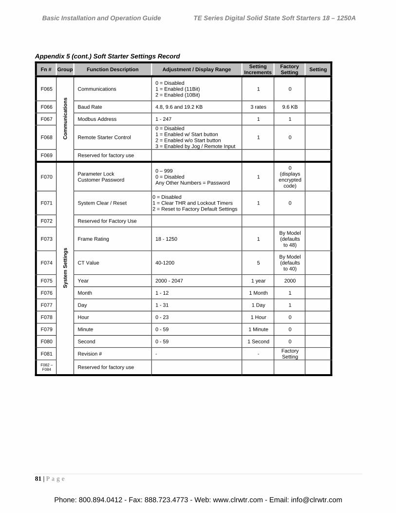
Basic Installation and Operation Guide TE Series Digital Solid State Soft Starters 18 – 1250A
81 | P a g e
Appendix 5 (cont.) Soft Starter Settings Record
Fn # Group Function Description Adjustment / Display Range
Setting Increments
Factory Setting
Setting
F065
Co
mm
un
icat
ion
s
Communications 0 = Disabled 1 = Enabled (11Bit) 2 = Enabled (10Bit)
1 0
F066 Baud Rate 4.8, 9.6 and 19.2 KB 3 rates 9.6 KB
F067 Modbus Address 1 - 247 1 1
F068 Remote Starter Control
0 = Disabled 1 = Enabled w/ Start button 2 = Enabled w/o Start button 3 = Enabled by Jog / Remote Input
1 0
F069 Reserved for factory use
F070
Sys
tem
Se
ttin
gs
Parameter Lock Customer Password
0 – 999 0 = Disabled Any Other Numbers = Password
1
0 (displays encrypted
code)
F071 System Clear / Reset 0 = Disabled 1 = Clear THR and Lockout Timers 2 = Reset to Factory Default Settings
1 0
F072 Reserved for Factory Use
F073 Frame Rating 18 - 1250 1 By Model (defaults
to 48)
F074 CT Value 40-1200 5 By Model (defaults
to 40)
F075 Year 2000 - 2047 1 year 2000
F076 Month 1 - 12 1 Month 1
F077 Day 1 - 31 1 Day 1
F078 Hour 0 - 23 1 Hour 0
F079 Minute 0 - 59 1 Minute 0
F080 Second 0 - 59 1 Second 0
F081 Revision # - - Factory Setting
F082 – F084 Reserved for factory use
Phone: 800.894.0412 - Fax: 888.723.4773 - Web: www.clrwtr.com - Email: [email protected]
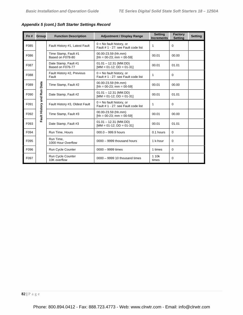
Basic Installation and Operation Guide TE Series Digital Solid State Soft Starters 18 – 1250A
82 | P a g e
Appendix 5 (cont.) Soft Starter Settings Record
Fn # Group Function Description Adjustment / Display Range Setting
IncrementsFactory Setting
Setting
F085
Fau
lt H
isto
ry a
nd
Ru
n D
ata
Fault History #1, Latest Fault 0 = No fault history, or Fault # 1 - 27: see Fault code list
1 0
F086 Time Stamp, Fault #1 Based on F078-80
00.00-23.59 (hh.mm) [hh = 00-23; mm = 00-59]
00.01 00.00
F087 Date Stamp, Fault #1 Based on F076-77
01.01 – 12.31 (MM.DD) [MM = 01-12; DD = 01-31]
00.01 01.01
F088 Fault History #2, Previous Fault
0 = No fault history, or Fault # 1 - 27: see Fault code list
1 0
F089 Time Stamp, Fault #2 00.00-23.59 (hh.mm) [hh = 00-23; mm = 00-59]
00.01 00.00
F090 Date Stamp, Fault #2 01.01 – 12.31 (MM.DD) [MM = 01-12; DD = 01-31]
00.01 01.01
F091 Fault History #3, Oldest Fault 0 = No fault history, or Fault # 1 - 27: see Fault code list
1 0
F092 Time Stamp, Fault #3 00.00-23.59 (hh.mm) [hh = 00-23; mm = 00-59]
00.01 00.00
F093 Date Stamp, Fault #3 01.01 – 12.31 (MM.DD) [MM = 01-12; DD = 01-31]
00.01 01.01
F094 Run Time, Hours 000.0 – 999.9 hours 0.1 hours 0
F095 Run Time, 1000 Hour Overflow
0000 – 9999 thousand hours 1 k-hour 0
F096 Run Cycle Counter 0000 – 9999 times 1 times 0
F097 Run Cycle Counter 10K overflow
0000 – 9999 10 thousand times 1 10k times
0
Phone: 800.894.0412 - Fax: 888.723.4773 - Web: www.clrwtr.com - Email: [email protected]