Embed Size (px)
Citation preview
Strata® CIX™
Product BulletinTOSHIBA
PBCIX-0063Nov. 5, 2007
Toshiba DP5000-Series Digital Telephones
Product SummaryToshiba’s next generation digital telephones are here. The DP5000 product line offers a sleek, low-profile design with a stylish tilt stand, an integrated headset interface and a full set of display and call handling features making Toshiba the obvious choice in leading-edge digital telephones. Toshiba continues to be proud of its backward compatibility allowing customers a new look on their desktop while maintaining much of their initial telephone system investment.
The most noticeable enhancements are the backlit displays, updated button placement and a high-end model with LCD key strips.
The telephone models are referenced by the total number of keys that are on the telephone (excluding the dial pad); the number of programmable keys have been specified in the descriptions and throughout the document.
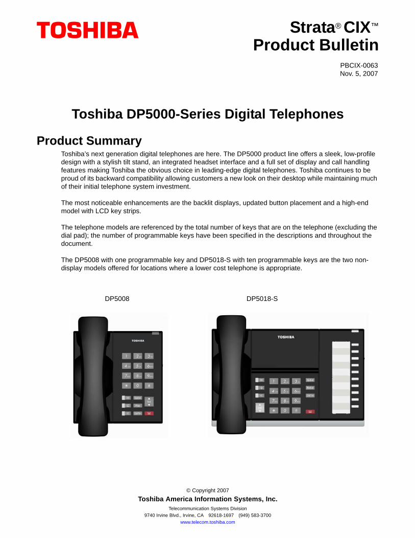
The DP5008 with one programmable key and DP5018-S with ten programmable keys are the two non-display models offered for locations where a lower cost telephone is appropriate.
DP5008 DP5018-S
© Copyright 2007
Toshiba America Information Systems, Inc.Telecommunication Systems Division
9740 Irvine Blvd., Irvine, CA 92618-1697 (949) 583-3700www.telecom.toshiba.com
Product Summary
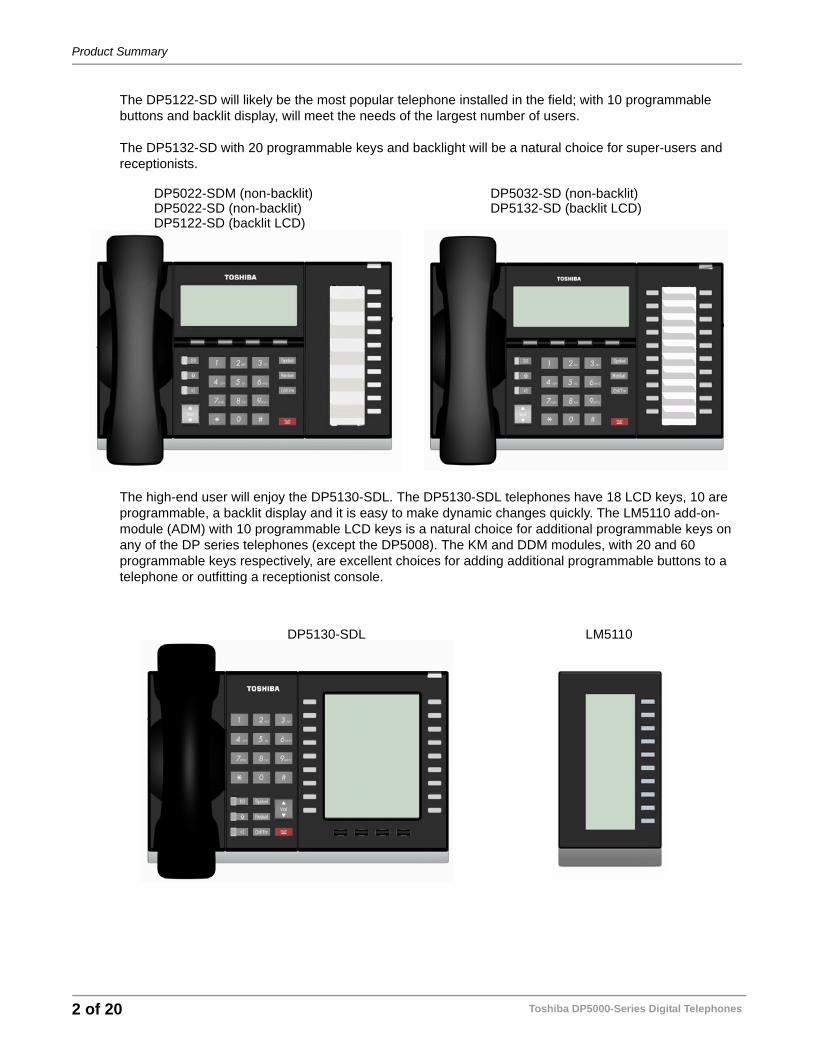
The DP5122-SD will likely be the most popular telephone installed in the field; with 10 programmable buttons and backlit display, will meet the needs of the largest number of users.
The DP5132-SD with 20 programmable keys and backlight will be a natural choice for super-users and receptionists.
The high-end user will enjoy the DP5130-SDL. The DP5130-SDL telephones have 18 LCD keys, 10 are programmable, a backlit display and it is easy to make dynamic changes quickly. The LM5110 add-on-module (ADM) with 10 programmable LCD keys is a natural choice for additional programmable keys on any of the DP series telephones (except the DP5008). The KM and DDM modules, with 20 and 60 programmable keys respectively, are excellent choices for adding additional programmable buttons to a telephone or outfitting a receptionist console.
DP5022-SDM (non-backlit)DP5022-SD (non-backlit)DP5122-SD (backlit LCD)
DP5032-SD (non-backlit)DP5132-SD (backlit LCD)
DP5130-SDL LM5110
Toshiba DP5000-Series Digital Telephones2 of 20
Positioning
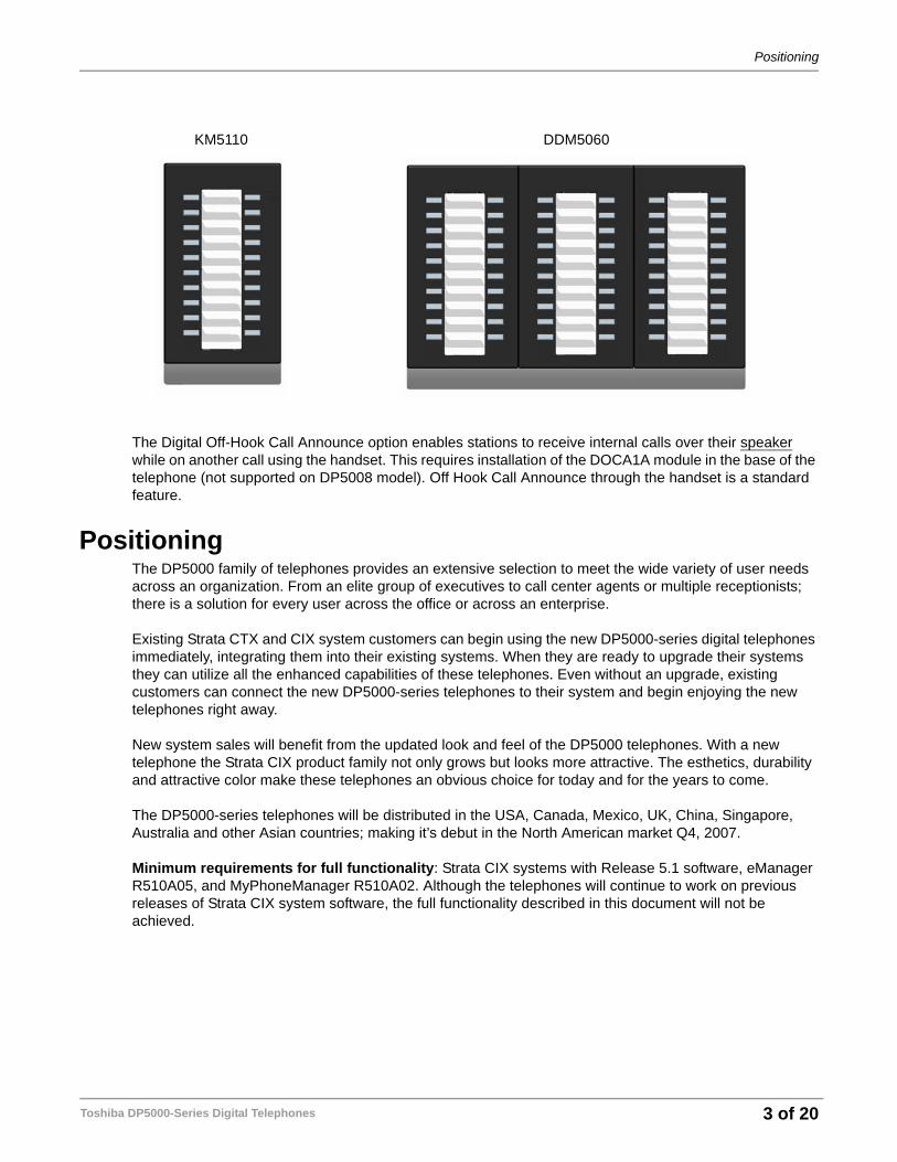
The Digital Off-Hook Call Announce option enables stations to receive internal calls over their speaker while on another call using the handset. This requires installation of the DOCA1A module in the base of the telephone (not supported on DP5008 model). Off Hook Call Announce through the handset is a standard feature.
PositioningThe DP5000 family of telephones provides an extensive selection to meet the wide variety of user needs across an organization. From an elite group of executives to call center agents or multiple receptionists; there is a solution for every user across the office or across an enterprise.
Existing Strata CTX and CIX system customers can begin using the new DP5000-series digital telephones immediately, integrating them into their existing systems. When they are ready to upgrade their systems they can utilize all the enhanced capabilities of these telephones. Even without an upgrade, existing customers can connect the new DP5000-series telephones to their system and begin enjoying the new telephones right away.
New system sales will benefit from the updated look and feel of the DP5000 telephones. With a new telephone the Strata CIX product family not only grows but looks more attractive. The esthetics, durability and attractive color make these telephones an obvious choice for today and for the years to come.
The DP5000-series telephones will be distributed in the USA, Canada, Mexico, UK, China, Singapore, Australia and other Asian countries; making it’s debut in the North American market Q4, 2007.
Minimum requirements for full functionality: Strata CIX systems with Release 5.1 software, eManager R510A05, and MyPhoneManager R510A02. Although the telephones will continue to work on previous releases of Strata CIX system software, the full functionality described in this document will not be achieved.
KM5110 DDM5060
Toshiba DP5000-Series Digital Telephones 3 of 20
Value Propositions
Value PropositionsThe DP5000 product family addresses the industry’s demand for an enhanced look with added functionality to the Toshiba brand of telephones. Toshiba listened to the voice of the customer (both dealers and end-users) to come up with the following enhancements:
Modern New Look • Sleek low profile — less than 1-inch thick• Black body with dark gray keys• Metallic silver curved tilt stand with eight adjustable positions• Key pad retained the traditional Toshiba layout, maintaining continuity and operability in mixed handset
deployments.
Large Display Area for Call Information • All LCDs are 24 characters wide• Four lines of LCD to display call information (on the DP5022-SDM, DP5022-SD, DP5122-SD,
DP5032-SD, and DP5132-SD telephones)• Nine lines of LCD on the DP5130-SDL telephone
LCD Key-Strip • Integrated in the DP5130-SDL telephone• Integrated in the LM5110 add-on module, this module is supported on all of the DP5000 series
telephones except the DP5008• Key labels are programmable via eManager 510A05, MyPhoneManager R510A02 (both local and
remote), or user programming mode• User programmable line and trunk labels • Feature labels – user selectable• Ease of deployment and dynamic changes
Backlight LCD• Available on: DP5122-SD, DP5132-SD, DP5130-SDL, and LM5110• Place the telephones anywhere: regular office, reception area, high-end home studio, hotel lounge,
low-light environments, etc.• LCD backlight can be set to always on, always off or synchronized which turns backlight on anytime
activity is sensed on the telephone and will automatically shut off after a period of time to conserve energy.
Handset/Mic Mute • All models have microphone and speaker capability (Note: The DP5008 does not have a microphone.)• Enhanced Mute - now the handset and microphone are muted simultaneously• The MIC key on the telephones toggles between Mic and Mute. When the Mic key is lit, hands free
communication is supported, when the Mic key is pressed and light is off, Mute is enabled.
Additional Characteristics• New LCD Technology — High Contrast Black-n-White LCD panel• Stylish Tilt Stand • Built-In Headset Interface — eliminates the need for technician to install optional interface• Built-in Carbon Handset Interface controlled by software
Toshiba DP5000-Series Digital Telephones4 of 20
Value Propositions
• Optional Speaker OCA for all models except the single line telephone• Two non-display models for budget-constrained installations
Features and CapabilitiesThe DP5008 telephone can support on-hook dialing and has a built-in headset interface. All of the other DP5000-series telephones:
• Support on-hook dialing• Speaker Off-hook Call announce (OCA)• Half-duplex speakerphone capability• Built-in headset interface• Carbon handset support
Notes
1. Setting of headset is by software setting in terminal.
2. Carbon type handset Setting is by software setting in terminal. This is an improvement of the DKT3000 that required cutting a jumper inside the telephone to use a carbon type handset.
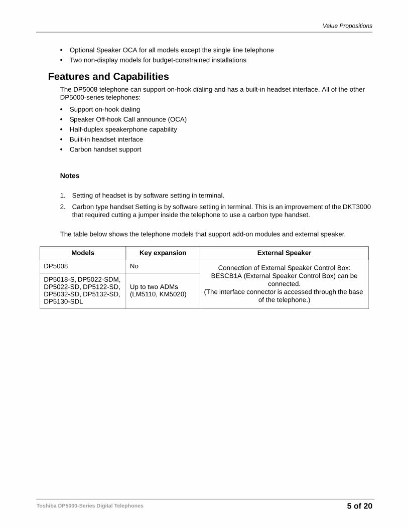
The table below shows the telephone models that support add-on modules and external speaker.
Models Key expansion External Speaker
DP5008 No Connection of External Speaker Control Box:BESCB1A (External Speaker Control Box) can be
connected.(The interface connector is accessed through the base
of the telephone.)
DP5018-S, DP5022-SDM, DP5022-SD, DP5122-SD, DP5032-SD, DP5132-SD, DP5130-SDL
Up to two ADMs (LM5110, KM5020)
Toshiba DP5000-Series Digital Telephones 5 of 20
Physical Specifications
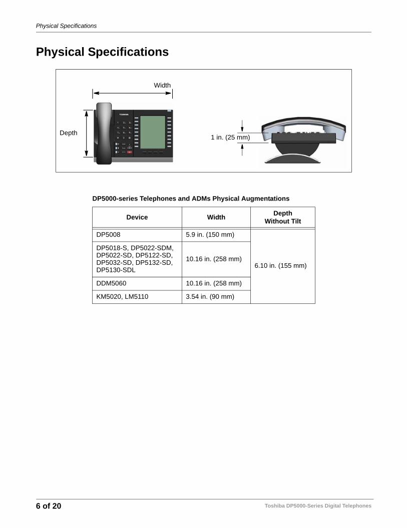
Physical Specifications
DP5000-series Telephones and ADMs Physical Augmentations
Device Width DepthWithout Tilt
DP5008 5.9 in. (150 mm)
6.10 in. (155 mm)
DP5018-S, DP5022-SDM, DP5022-SD, DP5122-SD, DP5032-SD, DP5132-SD, DP5130-SDL
10.16 in. (258 mm)
DDM5060 10.16 in. (258 mm)
KM5020, LM5110 3.54 in. (90 mm)
Width
Depth1 in. (25 mm)
Toshiba DP5000-Series Digital Telephones6 of 20
Physical Specifications
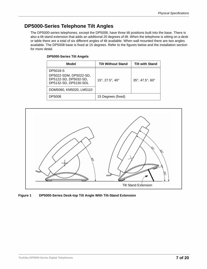
DP5000-Series Telephone Tilt AnglesThe DP5000-series telephones, except the DP5008, have three tilt positions built into the base. There is also a tilt stand extension that adds an additional 20 degrees of tilt. When the telephone is sitting on a desk or table there are a total of six different angles of tilt available. When wall mounted there are two angles available. The DP5008 base is fixed at 15 degrees. Refer to the figures below and the installation section for more detail.
Figure 1 DP5000-Series Desk-top Tilt Angle With Tilt-Stand Extension
DP5000-Series Tilt Angels
Model Tilt Without Stand Tilt with Stand
DP5018-SDP5022-SDM, DP5022-SD, DP5122-SD, DP5032-SD, DP5132-SD, DP5130-SDL
15°, 27.5°, 40° 35°, 47.5°, 60°
DDM5060, KM5020, LM5110
DP5008 15 Degrees (fixed)
Tilt Stand Extension
Toshiba DP5000-Series Digital Telephones 7 of 20
Compatibility and Migration
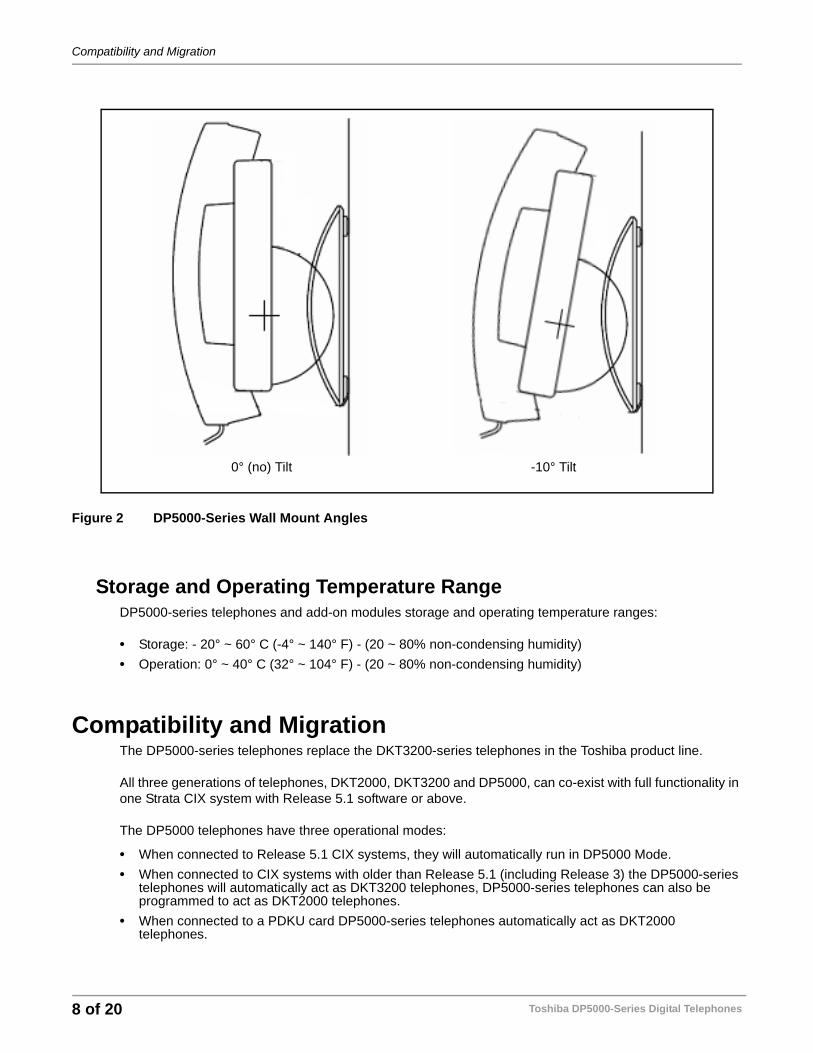
Figure 2 DP5000-Series Wall Mount Angles
Storage and Operating Temperature RangeDP5000-series telephones and add-on modules storage and operating temperature ranges:
• Storage: - 20° ~ 60° C (-4° ~ 140° F) - (20 ~ 80% non-condensing humidity)• Operation: 0° ~ 40° C (32° ~ 104° F) - (20 ~ 80% non-condensing humidity)
Compatibility and MigrationThe DP5000-series telephones replace the DKT3200-series telephones in the Toshiba product line.
All three generations of telephones, DKT2000, DKT3200 and DP5000, can co-exist with full functionality in one Strata CIX system with Release 5.1 software or above.
The DP5000 telephones have three operational modes:
• When connected to Release 5.1 CIX systems, they will automatically run in DP5000 Mode. • When connected to CIX systems with older than Release 5.1 (including Release 3) the DP5000-series
telephones will automatically act as DKT3200 telephones, DP5000-series telephones can also be programmed to act as DKT2000 telephones.
• When connected to a PDKU card DP5000-series telephones automatically act as DKT2000 telephones.
0° (no) Tilt -10° Tilt
Toshiba DP5000-Series Digital Telephones8 of 20
Order Information
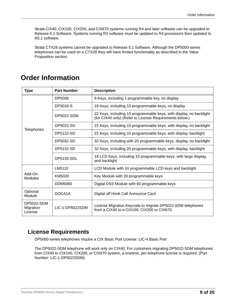
Strata CIX40, CIX100, CIX200, and CIX670 systems running R4 and later software can be upgraded to Release 5.1 Software. Systems running R3 software must be updated to R4 processors then updated to R5.1 software.
Strata CTX28 systems cannot be upgraded to Release 5.1 Software. Although the DP5000-series telephones can be used on a CTX28 they will have limited functionality as described in the Value Proposition section.
Order Information
License RequirementsDP5000-series telephones require a CIX Basic Port License: LIC-4 Basic Port
The DP5022-SDM telephone will work only on CIX40. For customers migrating DP5022-SDM telephones from CIX40 to CIX100, CIX200, or CIX670 system, a onetime, per-telephone license is required. (Part Number: LIC-1-DP5022SDM)
Type Part Number Description
Telephones
DP5008 8 Keys, including 1 programmable key, no display
DP5018-S 18 Keys, including 10 programmable keys, no display
DP5022-SDM 22 Keys, including 10 programmable keys, with display, no backlight (for CIX40 only) (Refer to License Requirements below.)
DP5022-SD 22 Keys, including 10 programmable keys, with display, no backlight
DP5122-SD 22 Keys, including 10 programmable keys, with display, backlight
DP5032-SD 32 Keys, including with 20 programmable keys, display, no backlight
DP5132-SD 32 Keys, including 20 programmable keys, with display, backlight
DP5130-SDL 18 LCD Keys, including 10 programmable keys, with large display, and backlight
Add-On-Modules
LM5110 LCD Module with 10 programmable LCD keys and backlight
KM5020 Key Module with 20 programmable keys
DDM5060 Digital DSS Module with 60 programmable keys
Optional Module DOCA1A Digital off Hook Call Announce Card
DP5022-SDM Migration License
LIC-1-DP5022SDM License Migration Keycode to migrate DP5022-SDM telephones from a CIX40 to a CIX100, CIX200 or CIX670.
Toshiba DP5000-Series Digital Telephones 9 of 20
Station Wiring, Loop Length, Telephone Power Factors
Station Wiring, Loop Length, Telephone Power FactorsConnections
All DP5000-series telephones with no ADM connected should use the standard, one-pair (two-wire) line cord included with the telephone.
Digital telephones connect to the MDF with standard twisted-pair telephone wiring. In most cases digital telephones can operate at up to 1000 feet when using a single pair, 24 AWG cable from telephone to equipment cabinet. Refer to Table , “Station Loop Lengths,” on page 11.
Digital telephones equipped with one or more ADMs require two pairs of wire, from the system to the station, to operate at maximum cable length. All digital telephones connected to systems with reserve battery power, regardless of cable length, should use two-pair cable.
The telephone wiring must be terminated at a modular station connect block (RJ11). The standard line cord, sent with each station is seven feet long. The maximum length line cord allowed is 25 feet.
Digital telephone cable runs must not have:
• Cable splits (single or double)
• Cable bridges of any length
• High resistance or faulty cable splices
The DP5000-series handset connects with a two-pair modular cable included with the telephone.
An ADM connects to the DP5000-series station only with the modular cable included with the ADM.
Toshiba DP5000-Series Digital Telephones10 of 20
Station Wiring, Loop Length, Telephone Power Factors
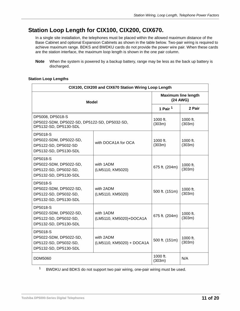
Station Loop Length for CIX100, CIX200, CIX670.In a single site installation, the telephones must be placed within the allowed maximum distance of the Base Cabinet and optional Expansion Cabinets as shown in the table below. Two-pair wiring is required to achieve maximum range. BDKS and BWDKU cards do not provide the power wire pair. When these cards are the station interface, the maximum loop length is shown in the one pair column.
Note When the system is powered by a backup battery, range may be less as the back up battery is discharged.
Station Loop Lengths
CIX100, CIX200 and CIX670 Station Wiring Loop Length
Model
Maximum line length(24 AWG)
1 Pair 1
1 BWDKU and BDKS do not support two pair wiring, one-pair wiring must be used.
2 Pair
DP5008, DP5018-SDP5022-SDM, DP5022-SD, DP5122-SD, DP5032-SD, DP5132-SD, DP5130-SDL
1000 ft. (303m)
1000 ft. (303m)
DP5018-SDP5022-SDM, DP5022-SD, DP5122-SD, DP5032-SDDP5132-SD, DP5130-SDL
with DOCA1A for OCA 1000 ft. (303m)
1000 ft. (303m)
DP5018-SDP5022-SDM, DP5022-SD,DP5122-SD, DP5032-SD,DP5132-SD, DP5130-SDL
with 1ADM(LM5110, KM5020)
675 ft. (204m) 1000 ft. (303m)
DP5018-SDP5022-SDM, DP5022-SD,DP5122-SD, DP5032-SD,DP5132-SD, DP5130-SDL
with 2ADM(LM5110, KM5020)
500 ft. (151m) 1000 ft. (303m)
DP5018-SDP5022-SDM, DP5022-SD,DP5122-SD, DP5032-SD,DP5132-SD, DP5130-SDL
with 1ADM(LM5110, KM5020)+DOCA1A
675 ft. (204m) 1000 ft. (303m)
DP5018-SDP5022-SDM, DP5022-SD,DP5122-SD, DP5032-SD,DP5132-SD, DP5130-SDL
with 2ADM(LM5110, KM5020) + DOCA1A
500 ft. (151m) 1000 ft. (303m)
DDM5060 1000 ft. (303m) N/A
Toshiba DP5000-Series Digital Telephones 11 of 20
Station Wiring, Loop Length, Telephone Power Factors
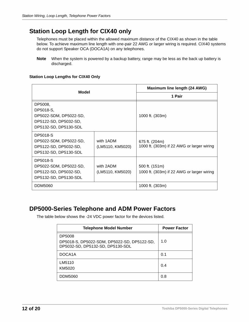
Station Loop Length for CIX40 onlyTelephones must be placed within the allowed maximum distance of the CIX40 as shown in the table below. To achieve maximum line length with one-pair 22 AWG or larger wiring is required. CIX40 systems do not support Speaker OCA (DOCA1A) on any telephones.
Note When the system is powered by a backup battery, range may be less as the back up battery is discharged.
Station Loop Lengths for CIX40 Only
DP5000-Series Telephone and ADM Power FactorsThe table below shows the -24 VDC power factor for the devices listed.
ModelMaximum line length (24 AWG)
1 Pair
DP5008,DP5018-S,DP5022-SDM, DP5022-SD,DP5122-SD, DP5032-SD,DP5132-SD, DP5130-SDL
1000 ft. (303m)
DP5018-SDP5022-SDM, DP5022-SD,DP5122-SD, DP5032-SD,DP5132-SD, DP5130-SDL
with 1ADM(LM5110, KM5020)
675 ft. (204m)1000 ft. (303m) if 22 AWG or larger wiring
DP5018-SDP5022-SDM, DP5022-SD,DP5122-SD, DP5032-SD,DP5132-SD, DP5130-SDL
with 2ADM(LM5110, KM5020)
500 ft. (151m)1000 ft. (303m) if 22 AWG or larger wiring
DDM5060 1000 ft. (303m)
Telephone Model Number Power Factor
DP5008DP5018-S, DP5022-SDM, DP5022-SD, DP5122-SD, DP5032-SD, DP5132-SD, DP5130-SDL
1.0
DOCA1A 0.1
LM5110KM5020
0.4
DDM5060 0.8
Toshiba DP5000-Series Digital Telephones12 of 20
Installation Guidelines
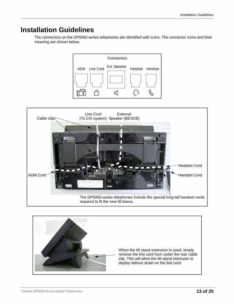
Installation GuidelinesThe connectors on the DP5000-series telephones are identified with icons. The connector icons and their meaning are shown below.
Connectors
ADM HandsetHeadsetExt. Speaker
Line Cord
Line Cord
ADM Cord Handset Cord
Headset Cord
ExternalSpeaker (BESCB)(To CIX system)
The DP5000-series telephones include the special long-tail handset cordsrequired to fit the new tilt bases.
Cable clips
When the tilt stand extension is used, simplyremove the line cord from under the rear cableclip. This will allow the tilt stand extension todeploy without strain on the line cord.
Toshiba DP5000-Series Digital Telephones 13 of 20
Installation Guidelines
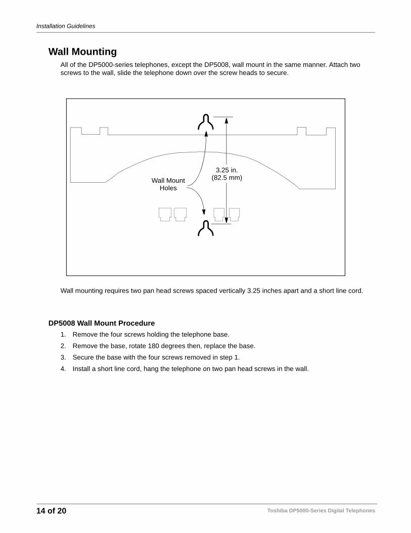
Wall MountingAll of the DP5000-series telephones, except the DP5008, wall mount in the same manner. Attach two screws to the wall, slide the telephone down over the screw heads to secure.
Wall mounting requires two pan head screws spaced vertically 3.25 inches apart and a short line cord.
DP5008 Wall Mount Procedure1. Remove the four screws holding the telephone base.
2. Remove the base, rotate 180 degrees then, replace the base.
3. Secure the base with the four screws removed in step 1.
4. Install a short line cord, hang the telephone on two pan head screws in the wall.
Wall MountHoles
3.25 in.(82.5 mm)
Toshiba DP5000-Series Digital Telephones14 of 20
Add-On Module Installation
Add-On Module InstallationEach add-on module is packaged with the metal brackets and screws used to attach the ADM to a DP5000-series telephone, or another ADM. The ADM package also includes the short line cord to connect the telephone to the ADM or the ADM to a second ADM.
The ADM and telephone bases are connected together with metal brackets to form a single unit. The ADM and telephones tilt independently.
The ADM Installation follows:
1. Unplug the line cord from the telephone.
2. Use the brackets and screws included in the box to attach the ADM base to the telephone base. Refer to Figure 3.
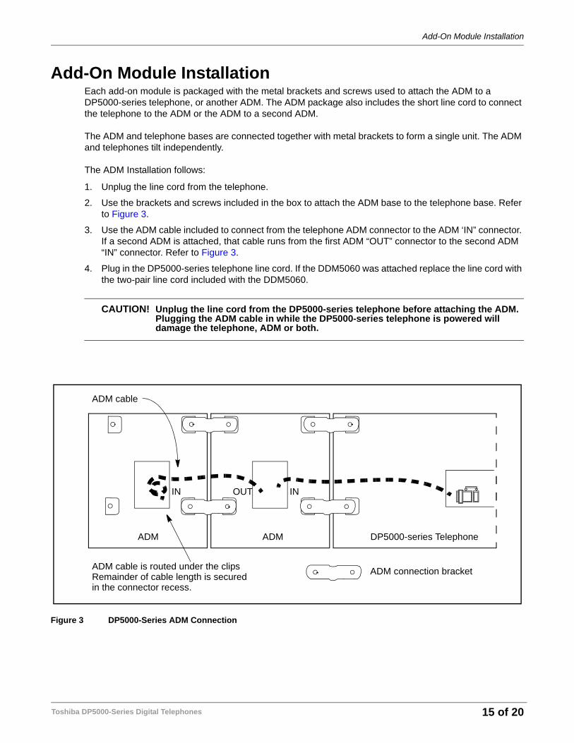
3. Use the ADM cable included to connect from the telephone ADM connector to the ADM ‘IN” connector. If a second ADM is attached, that cable runs from the first ADM “OUT” connector to the second ADM “IN” connector. Refer to Figure 3.
4. Plug in the DP5000-series telephone line cord. If the DDM5060 was attached replace the line cord with the two-pair line cord included with the DDM5060.
CAUTION! Unplug the line cord from the DP5000-series telephone before attaching the ADM. Plugging the ADM cable in while the DP5000-series telephone is powered will damage the telephone, ADM or both.
Figure 3 DP5000-Series ADM Connection
DP5000-series TelephoneADMADM
ADM connection bracket
ADM cable
ADM cable is routed under the clipsRemainder of cable length is securedin the connector recess.
INOUTIN
Toshiba DP5000-Series Digital Telephones 15 of 20
Telephone Administration Reference:
Telephone Administration Reference:To Initialize a DP5000-series telephone:
1. Press 3+6+9+Hold (simultaneously)
2. Press MODE softkey
3. Press Msg key
4. Press Hold
5. Press Volume Up
6. Press Msg key
7. Press Hold
8. Go off-hook then on-hook to exit programming mode.
This will reset all the programming mode options settings back to the factory default.
The DP5000-series telephones can be programmed in the same manner as the DKT3200-series telephones with the following considerations:
DP5130-SDL LCD Keystrip Setup eManager version V5.10A05 or later is required.
Assign Keystrip Label Resources to device1. Log into eManager
2. Select Advanced Configuration > Station > Assignments
3. From the station list on the right hand side of the screen, choose the extension number to change.
4. Click on the DKT tabFB 03: Keystrip Button Quantity should be changed to 10FB 39: LARGE LCD PHONE should be changed to DP5130.
5. Click on the Submit button.
Note To change this DN to another DP5000-series telephone or to a DKT, with a key type other than 10 use the following steps.1. Change FB 39 to “Not DP5130”2. Press Submit.3. Change FB 03 to a value other than 10.4. Press Submit.
Program Keystrip Labels1. Log into eManager
2. Select Advanced Configuration > Station > Assignments
3. From the station list on the right hand side of the screen, choose the extension number to change.
4. Click on the Key tab
5. Click on the button to be setup
6. Choose the feature to be applied from the feature list on the right-hand side.
Toshiba DP5000-Series Digital Telephones16 of 20
Telephone Administration Reference:
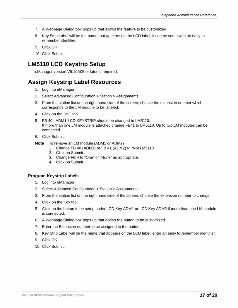
7. A Webpage Dialog box pops up that allows the feature to be customized
8. Key Strip Label will be the name that appears on the LCD label, it can be setup with an easy to remember identifier.
9. Click OK
10. Click Submit.
LM5110 LCD Keystrip SetupeManager version V5.10A05 or later is required.
Assign Keystrip Label Resources1. Log into eManager
2. Select Advanced Configuration > Station > Assignments
3. From the station list on the right hand side of the screen, choose the extension number which corresponds to the LM module to be labeled.
4. Click on the DKT tab
5. FB 40: ADM1-LCD KEYSTRIP should be changed to LM5110. If more than one LM module is attached change FB41 to LM5110. Up to two LM modules can be connected.
6. Click Submit.
Note To remove an LM module (ADM1 or ADM2)1. Change FB 40 (ADM1) or FB 41 (ADM2) to “Not LM5110”2. Click on Submit.3. Change FB 4 to “One” or “None” as appropriate.4. Click on Submit.
Program Keystrip Labels1. Log into eManager
2. Select Advanced Configuration > Station > Assignments
3. From the station list on the right hand side of the screen, choose the extension number to change.
4. Click on the Key tab
5. Click on the button to be setup under LCD Key ADM1 or LCD Key ADM2 if more than one LM module is connected.
6. A Webpage Dialog box pops up that allows the button to be customized
7. Enter the Extension number to be assigned to the button.
8. Key Strip Label will be the name that appears on the LCD label, enter an easy to remember identifier.
9. Click OK
10. Click Submit.
Toshiba DP5000-Series Digital Telephones 17 of 20
End-user Reference Guide
End-user Reference GuideProgramming changes can be done through the telephone or through MyPhoneManager. Following are the instructions using the telephone.
Volume ControlThe following instructions apply to all telephones, except DP5008.
To adjust the handset volumePress the Vol to increase volume and Vol to decrease volume during the call. When you hang up, the volume returns to the default setting.
To adjust the speaker volume for internal/external calls and background music1. Press Spkr. 2. Press an extension button - you hear dial tone.
3. Press the Vol to increase volume and Vol to decrease volume. This volume setting applies to all calls until changed.
To adjust Ring Tone, Hands free Answerback and Speaker Off-hook Call AnnounceMake sure the telephone is idle and the handset is on-hook. Press the Vol to increase volume and Vol to decrease volume. This adjusts volume for your telephone’s ring tone, Hands free Answerback and Speaker Off-hook Call Announce simultaneously.
To adjust handset Beep Tone1. With the handset off-hook, dial the Beep Tone Adjustment Code #6101 (default code). You hear busy
tone.
2. Press Vol or to reach the desired level.
Volume Control for DP5008 TelephonePress the Vol to increase volume and Vol to decrease volume during it.
To adjust the handset volumePress the Vol to increase volume and Vol to decrease volume during the call. When you hang up, the volume returns to the default setting.
To adjust the speaker volume for internal/external calls and background music1. Press Spkr. 2. Press an extension button - you hear dial tone.
3. Press the Vol to increase volume and Vol to decrease volume. This volume setting applies to all calls until changed.
To adjust Ring ToneMake sure the telephone is idle and the handset is on-hook. Press the Vol to increase volume and Vol to decrease volume.
Toshiba DP5000-Series Digital Telephones18 of 20
Backlight Options
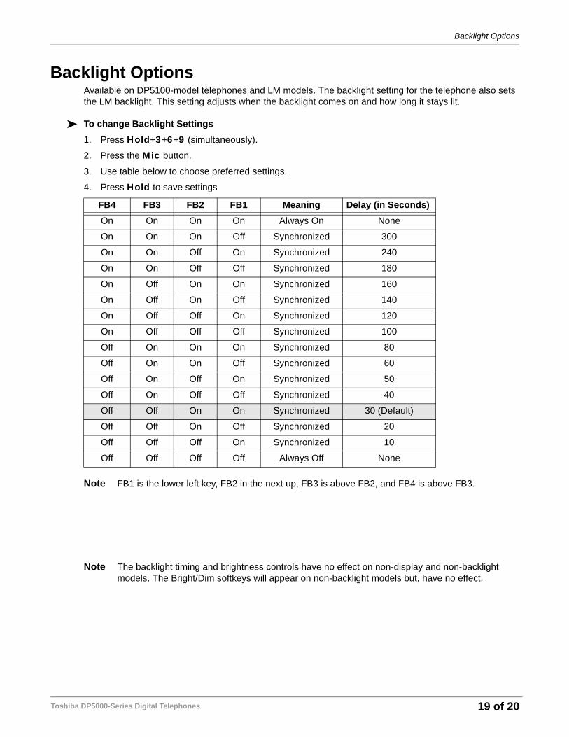
Backlight OptionsAvailable on DP5100-model telephones and LM models. The backlight setting for the telephone also sets the LM backlight. This setting adjusts when the backlight comes on and how long it stays lit.
To change Backlight Settings1. Press Hold+3+6+9 (simultaneously).
2. Press the Mic button.
3. Use table below to choose preferred settings.
4. Press Hold to save settings
Note FB1 is the lower left key, FB2 in the next up, FB3 is above FB2, and FB4 is above FB3.
Note The backlight timing and brightness controls have no effect on non-display and non-backlight models. The Bright/Dim softkeys will appear on non-backlight models but, have no effect.
FB4 FB3 FB2 FB1 Meaning Delay (in Seconds)On On On On Always On None
On On On Off Synchronized 300
On On Off On Synchronized 240
On On Off Off Synchronized 180
On Off On On Synchronized 160
On Off On Off Synchronized 140
On Off Off On Synchronized 120
On Off Off Off Synchronized 100
Off On On On Synchronized 80
Off On On Off Synchronized 60
Off On Off On Synchronized 50
Off On Off Off Synchronized 40
Off Off On On Synchronized 30 (Default)
Off Off On Off Synchronized 20
Off Off Off On Synchronized 10
Off Off Off Off Always Off None
Toshiba DP5000-Series Digital Telephones 19 of 20
Brightness Control
Brightness ControlAvailable on DP5100-model telephones and the LM5110 ADM.
To change the LCD back light brightness on the DP5100-model telephone and the LM5110 ADM:
1. Press Hold+3+6+9 (simultaneously).
2. Press Bright softkey on the telephone to increase brightness. On the LM5110 use the Bright softkey.
3. Press Dim softkey to decrease brightness. On the LM5110 use the Dim softkey.
4. Lift the handset off-hook / on-hook to save the settings.
LCD Contrast AdjustmentsAvailable on all DP5100-model LCD models and the LM5110 ADM.
To adjust the LCD contrast on the DP5100-model telephones1. Press and hold down the Mic button.
2. Press and release Vol or Vol repeatedly.
Note Holding the Vol key does not continue to change the setting. The key must be pressed for each step of contrast change.
To adjust the LCD contrast on the LM51101. Press Hold+3+6+9 (simultaneously).
2. Press Contrast + key to increase contrast.
3. Press Contrast - key to decrease contrast.
4. Lift the handset off-hook / on-hook to save settings.
Note Holding the softkey does not continue to change the setting. The softkey must be pressed for each step of contrast change.
Mic/Mute KeyMute on the DP5000-series telephones mutes not only the microphone but also the handset microphone as well. The MIC key on the telephones toggles between Mic and Mute. When Mic key is lit, hands free communication is supported, when Mic key is pressed and light is off, Mute is enabled.
• During a hands free conversation, press the Mic key, the red indicator will turn off; the microphone and handset are muted.
• Press the Mic key again to resume hands free communication, the red indicator will turn on.
Program LCD Keystrip Labels (for DP5130-SDL & LM5110)1. Dial #9876 (or press the flexible Program key)
2. Press the speaker button.
3. Press the key you wish to label.
4. Use the dial pad to enter the label.
5. Press the key labeled in step 3 to save the setting.
6. To program another key, repeat steps 2-5.
Toshiba DP5000-Series Digital Telephones20 of 20