Embed Size (px)
Citation preview
Journal of Engineering and Sustainable Development, Vol. 20, No.04, July 2016 www.jeasd.org (ISSN 2520-0917)
277
;
TORSION PLUS BENDING AND SHEAR ON REINFORCED
CONCRETE BEAMS
Awadh E. Ajeel*
Lecturer., Highway and Transportation Engineering Department, Al-Mustansiriyah University,
Baghdad, Iraq.
Abstract: This paper is relevant with reinforced concrete beams subjected to combined torsional
moments, bending moments and its comitant shear forces. Six identical beams in its dimensions and
reinforcement, but different in the external loading setup were tested. The loading setup was applied in
a manner depending on gradual ratio of bending moment to torsional moment; thereby, two beams
were references to the other four ones. Experimental results revealed that, the loading setup is
considerably effective factor on the structural behavior of the reinforced concrete beam. So that,
through the loading setup, the presence of torsional moment leads to enhance the resistance of the beam
over than 200% against combined loads than pure bending moment or torsional moment only. Also, the
loading setup is capable of restoring the stiffness, maintaining the flexure mode of failure and raising
the design safety factor for combined loaded reinforced concrete beams subjected to combined
torsional moments, bending moments and shear forces.
Keywords: beam, torsion, bending moment, shear, concrete, loading setup
المسلحة الخرسانية عتاباأل على والقص االنحناء إلى باإلضافة اللي
يتعلق هذا البحث باألعتاب الخرسانية المسلحة المعرضة إلى اختالط عزوم اللي، عزوم االنحناء وما يرافقها من قوى القص. الخالصة:
تتألف نماذج البحث من ستة أعتاب متماثلة من حيث األبعاد والتسليح، ولكنها مختلفة من حيث طريقة تحميلها الخارجي. تم تسليط
من األعتاب تمثل مراجع مقارنة نسبة متدرجة من عزم االنحناء إلى عزم اللي؛ وبذلك كان هناك اثنان األحمال وفق أسلوب يعتمد على
. ةالمسلح ةالخرساني ةأظهرت النتائج العملية أن أسلوب التحميل يمثل عامل مؤثر على السلوك اإلنشائي للعتب.تاب األربعة األخرىعلأل
% أمام األحمال المركبة 200فوق ما يزيد عن ةم اللي يؤدي إلى تعزيز مقاومة العتبومن ذلك أن أسلوب التحميل يجعل من وجود عز
عن مقاومتها لعزم االنحناء الصرف أو عزم االلتواء الصرف كل على حدة. وإلى جانب ذلك فإن كيفية التحميل قادرة على استعادة
لألعتاب الخرسانية المسلحة مركبة التحميل بتعريضها إلى المتانة، الحفاظ على نمط فشل انثناء وزيادة معامل األمان التصميمي
.إجهادات مركبة من عزوم اللي، عزوم االنحناء وقوى القص
1. Introduction
It is agreed that, loading on reinforced concrete beams, especially spandrel one, is
mainly combined of bending moment and shear force as well minor torsional moment.
Vol. 20, No. 04, July 2016
ISSN 2520-0917
www.jeasd.org

Journal of Engineering and Sustainable Development, Vol. 20, No.04, July 2016 www.jeasd.org (ISSN 2520-0917)
278
Despite bending moment is always decisive for alike combination of loading [1-3],
however, load points of action and positions need to be observed its effects to
assurance corresponded structure’s performance and efficiency under a certain
distribution of loading. Many researchers investigated beams subjected to pure torsion
only [4,5] or combined torsion, bending and shear force [3, 6 and 7] through external
point loads acting with eccentricity to the beam axis at or near its supporting zones.
Whilst, another researchers [2, 8 and 9] conducted their papers to investigate beams
behaviors under combined torsion, bending and shear force produced by eccentric
load in the beam middle zone.
Almost of previous researches indicated decrease in strength and stiffness of beams
tested under combined shear and bending stresses propagated from eccentric loading.
Some researchers determined ratios of bending moment/torsional moment (λ) in
which bending moment can be dominant on the beam structural behavior and failure
mode. The ratio of dominant bending moment via precede researches is (λ ≥ 2.5) [3],
(λ ≥ 2.0) [1] and (λ > 1.0) [6] where beams configurations and test setup were
different in each research respectively.
Recently, strengthening of structures is become more intended and focused due to
many professional, environmental and economic considerations. Thereby,
strengthening of concrete structure can be achieved by; increasing its cross-sectional
area with comitant transverse reinforcement, using externally bonded steel plates or
post-tensioning the structure to apply axial load [10]. Fiber reinforced polymer (FRP)
carbon [11-13], glass [14, 15] and composites [16] bonded externally or embedded
internally [17] in modern options used successfully for strengthening beams subjected
to combined loading. Additionally, steel fibers (SF) are another strengthening option
for beams suffering from high tensile stresses under combined loading [4, 5 and 7].
2. Objective
The present paper aims to study the effects of torsional load presence in the
structural behavior of reinforced concrete beams subjected to combined bending and
shear stresses firstly, and seeks about how loading can be distributed to attain more
efficiency for the beams without using any further strengthening technique secondly.
3. Experimental Work
3.1. Testing Program
In this paper, loading is arranged to apply a concentric point(s) load in beam
middle zone as well as two eccentric points load at the beam supports (ends). So, four
beam specimens have gradual descended values of (λ) were tested under torsion
moment plus bending moment and shear. Another two beam specimens; one under
pure bending moment and the other under pure torsion moment, were tested in a
manner to be references specimens for the other four ones.

Journal of Engineering and Sustainable Development, Vol. 20, No.04, July 2016 www.jeasd.org (ISSN 2520-0917)
279
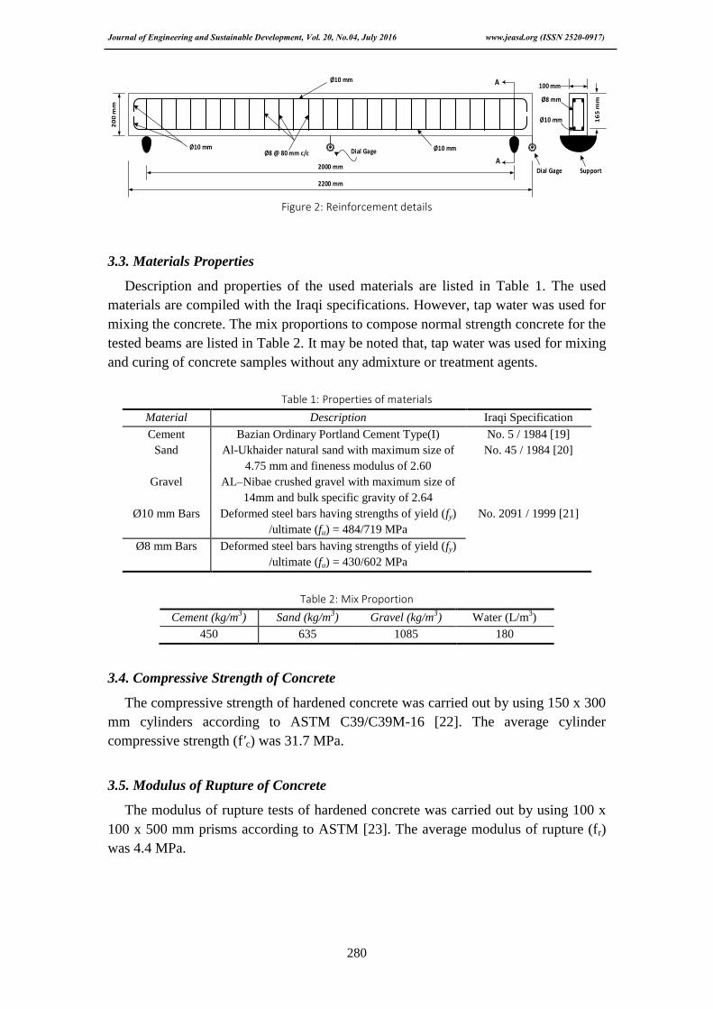
3.2. Specimens Details
The total number of specimens is six reinforced concrete beams and two of them
are references. The first reference beam (B1) was tested under central point load only
to be subjected to moments producing bending without torsion, so the (λ) of the beam
is infinity (∞). The opposite reference beam (B6) was subjected to pure torsion and
tested under eccentric two halves load at the ends of the beam (support zones) to make
the beam free of bending moments with (λ) value equals zero (0). The rest four beam
specimens are the main specimens of the study and they were tested under combined
bending and torsional moment as well of course their comitant shear stresses. Loading
setup of the main beams is similar to beam specimen (B6) for producing torsional
moments; however, bending moments were produced by additional point(s) load in
the beam midspan to achieve the study objectives. The external loading setup for the
specimens is shown in Fig. 1 while all these specimens are identical in dimension and
reinforcement, as shown in Fig. 2. All the tested beams were cast with normal strength
concrete and dimensions of 100 x 200 x 2200 mm. The dimensions, longitudinal
reinforcement and transverse reinforcement of the beams are selected to be within the
limitations of ACI Code 318M-14 [18] to ensure the flexure mode of failure.
T
V
M
B1λ = ∞
P
P/2
PL/4
T
V
M
B2λ = 2.0
P/2
P/4
PL/8
P/4P/4
PL/16
T
V
M
B3λ = 1.9
P/4
P/4
0.475PL/4
P/4P/4
PL/16
P/4
T
V
M
B4λ = 1.8
P/4
P/4
0.450PL/4
P/4P/4
PL/16
P/4
T
V
M
B5λ = 1.7
P/4
P/4
0.425PL/4
P/4P/4
PL/16
P/4
T
V
M
B6λ = 0
P/2
PL/8
P/2
Figure 1: Loading setup for specimens
Journal of Engineering and Sustainable Development, Vol. 20, No.04, July 2016 www.jeasd.org (ISSN 2520-0917)
280
20
0 m
m
16
5 m
m
A
A
Ø10 mmØ8 @ 80 mm c/c Dial Gage
Dial Gage Support
2200 mm
2000 mm
Ø10 mm
Ø10 mm
Ø8 mm
Ø10 mm
Figure 2: Reinforcement details
3.3. Materials Properties
Description and properties of the used materials are listed in Table 1. The used
materials are compiled with the Iraqi specifications. However, tap water was used for
mixing the concrete. The mix proportions to compose normal strength concrete for the
tested beams are listed in Table 2. It may be noted that, tap water was used for mixing
and curing of concrete samples without any admixture or treatment agents.
Table 1: Properties of materials
Material Description Iraqi Specification
Cement Bazian Ordinary Portland Cement Type(I) No. 5 / 1984 [19]
Sand Al-Ukhaider natural sand with maximum size of
4.75 mm and fineness modulus of 2.60
No. 45 / 1984 [20]
Gravel AL–Nibae crushed gravel with maximum size of
14mm and bulk specific gravity of 2.64
Ø10 mm Bars Deformed steel bars having strengths of yield (fy)
/ultimate (fu) = 484/719 MPa
No. 2091 / 1999 [21]
Ø8 mm Bars Deformed steel bars having strengths of yield (fy)
/ultimate (fu) = 430/602 MPa
Table 2: Mix Proportion
Cement (kg/m3) Sand (kg/m
3) Gravel (kg/m
3) Water (L/m
3)
450 635 1085 180
3.4. Compressive Strength of Concrete
The compressive strength of hardened concrete was carried out by using 150 x 300
mm cylinders according to ASTM C39/C39M-16 [22]. The average cylinder
compressive strength (f'c) was 31.7 MPa.
3.5. Modulus of Rupture of Concrete
The modulus of rupture tests of hardened concrete was carried out by using 100 x
100 x 500 mm prisms according to ASTM [23]. The average modulus of rupture (fr)
was 4.4 MPa.

Journal of Engineering and Sustainable Development, Vol. 20, No.04, July 2016 www.jeasd.org (ISSN 2520-0917)
281
3.6. Instrumentations and Testing
All the beams were tested with clear span (L) of 2000 mm between supports and
firstly colored by white paint to facilitate detection of cracks. One dial gage of 0.01
mm divisions and 50 mm capacity was positioned at the beam midspan to measure
deflection when bending moment is a part of loading. Occasionally, in case of torsion
loading presence, two dial gages of 0.002 mm divisions and 30 mm capacity were
positioned at one end of the beam span to measure the vertical movements of the
bottom fiber at the opposite corners of the beam end. So, the average of twisting angle
can be calculated approximately through a simple method as shown in Fig. 3.c
Testing machine is a universal (MFL) type of 3000 kN maximum capacity; which
shown in Fig. 3. Loading was applied with 5 kN gradual increment and continued up
to failure. During test, midspan deflection and/or twisting angle were measured at
each stage of load increase.
Do
wn
M
ov
em
en
t
Original Bottom Fibers Posision
ф
ф
Up
M
ov
em
en
t
a: Testing machine b: Test setup c: Angle of twist measuring
Figure 3: Testing details
4. Results and Discussion
Test results in terms of ultimate load (Pu) and midspan deflection (Δ) are arranged
in Table 3 and discussed more detailed under specific topics therein. The ultimate
strength means the total applied loads on the tested beam at failure.
Table 3: Test Results
Beam Symbol M/T (λ) Pu (kN) Δ (mm) ф (deg.) Failure Mode
B1 ∞ 25 1.94 0 Flexure
B2 2 35 3.42 3.45 Flexure
B3 1.9 52 4.83 5.35 Flexure
B4 1.8 60 5.81 6.29 Flexure
B5 1.7 73 7.85 6.65 Flexure-Shear
B6 0 35 0 4.80 Shear
4.1. Beam Strength
The recorded load, at any stage of test, is the total applied load from the hydraulic
machine, so the strength of the tested beam is indicated by the ultimate applied load
(Pu) at or closely near failure. In the present work, the four main beam specimens (B2-
B5) exhibited increases in total strength exceeded its references beams (B1 and B6).

Journal of Engineering and Sustainable Development, Vol. 20, No.04, July 2016 www.jeasd.org (ISSN 2520-0917)
282
The strength of the specimens enhanced gradually, higher than references, to reach
greater than 200% in beam specimen (B5) and this result revealed the loading setup
high action in raising the beam capacity against combined bending and torsion to
emphasize the conclusion of Ref [3]. In addition, the results indicated that for the
combined loading; when the ratio of bending moment/torsional moment (λ) of the
beam decreased, its strength will increase and even the rate of (λ) decrease was small
the rate of strength increase was considerable. The enhancement of beams strengths is
graphed in Fig. 4.a.
The original ultimate strength capacity came from pure type of loading on the
reference beams; therefore, (T₀) is the torsional ultimate strength of beam specimen
(B6) while (M₀) plus (V₀) are the bending and shear components of the ultimate
strength of beam specimen (B1) respectively. While for the main beams, the ultimate
load which represents the beam strength is analyzed into torsional, bending and shear
components. Table 4 contains the components of the ultimate strength of each tested
beam which are collected to establish the interaction diagrams and other curves.
Table 4: Ultimate load components
M/T (λ) T
(kN.m)
T₀
(kN.m)
T/T₀ M
(kN.m)
M₀
(kN.m)
M/M₀ V
(kN)
V₀
(kN)
V/V₀
∞ 0 8.75 0 12.50 12.50 1.0 12.50 12.50 1.0
2 4.38 0.5 8.75 0.70 8.75 0.70
1.9 6.50 0.74 12.35 0.99 13.0 1.04
1.8 7.50 0.86 13.50 1.08 15.0 1.20
1.7 9.13 1.04 15.51 1.24 18.25 1.46
0 8.75 1.0 0 0 0 0
In this paper, the loading setup was directional agent to control (λ) values. When
the concentric points load more diverge, the ratio of torsional moment increases and
leads to decrease (λ) value. It can be noticed that, the decreasing of (λ) leads to
enhance the total strength of the beam combined loading. However, other components
of strength get improvement due to decreased (λ) and with (λ = 1.7) the beam is
capable to resist torsion, bending and shear well than when it in case of resisting pure
flexural or torsional only. Increasing the moment ratio to be (λ = 2) means the
combined loaded beam failure in torsion, bending or shear less than its capacity when
it is subjected to pure torsion on bending moment but with higher resultant strength in
comparison with its pure bending or torsion reference and that is clear in Fig. 4.b.

Journal of Engineering and Sustainable Development, Vol. 20, No.04, July 2016 www.jeasd.org (ISSN 2520-0917)
283
a: Total strength b: Components strengths
Figure 4: Strength of the tested beams
4.2. Interaction Diagrams
The interaction diagrams are very important tool for some design procedures. So,
establishing these diagrams through experimental results leads to check its confidence
and safety factors. In the present work, the main interaction diagrams for beam
strength against combined bending and Torsional moments are illustrated in
comparison with theoretical limits and other researches results.
Torsional capacity is interactional in non-dimensional diagrams with flexural
capacity in Fig. 5.a and with shear capacity in Fig. 5.b. For the two present
experimental diagrams, only one beam of combined specimens (B2) where (λ = 2) has
strength less than the theoretical curves, however, by increasing the amount of torsion
to decrease the value of (λ), the strength of beam become greater than both the
theoretical curves and the experimental results of [2, 9] researches. It is clear that the
trend of the present results dispersion depends on the loading setup, so that the test
configurations of [2, 9] are illustrated in Figs. 7.a and 7.b.
a: Torsion vis. bending b: Torsion vis. shear
Figure 5: Non-dimensional interaction diagrams of the tested beams compared to others

Journal of Engineering and Sustainable Development, Vol. 20, No.04, July 2016 www.jeasd.org (ISSN 2520-0917)
284
Torsional capacity is also interactional with shear capacity in Fig. 6.a to compare it
with the experimental results of [8] in Fig. 6.b where linear theoretical interaction is
concluded. The present results did not coincide with the theoretical interaction and
dispersed orthogonally with this line to be always above it. The non-conformity
between the theoretical line and present results is because of the loading setup
different to that of [8] shown in Fig. 7.c. Since the achieved results, the loading setup
is very effective on the interaction diagrams of reinforced concrete beams subjected to
combined torsion, bending and shear.
a: The present results b: Ref [8] results
Figure 6: Torsion-shear interaction diagrams of the tested beams compared to others
T
V
M
P
T
V
M
4P/6
P/6
P/6
T
V
M
P
P/2
PL/8
P.e/2
a: Ref [2] setup b: Ref [9] setup c: Ref [8] setup
Figure 7: Loading setup of other referred researches
4.3. Flexural and Torsional Stiffness
Experimental observing of a beam stiffness depended on its response in terms of
deflection and twisting angle values under the applied load, therefore, bending
moment-midspan deflection curve is illustrated to clarify the flexural stiffness and
also torsional moment-twisting angle curve is illustrated to clarify the torsional
stiffness of the tested beams as in Fig. 8.

Journal of Engineering and Sustainable Development, Vol. 20, No.04, July 2016 www.jeasd.org (ISSN 2520-0917)
285
a: Flexural stiffness b: Torsional stiffness
Figure 8: Stiffness of the tested beams
Generally, the tested beams exhibited similar behavior. However, Fig. 8.a revealed
that the flexural stiffness of the tested beams is greater than its torsional stiffness in
Fig. 8.b and that is rational because elastic modulus of any beam is greater than its
shearing modulus. It is clear that when the beam is subjected to pure flexure (λ = ∞)
or pure torsion (λ = 0) only its stiffness will be better than one when it is subjected to
combined flexure and torsion and this result complies with Ref [1]. Another achieved
result is increasing the ratio of torsion to the bending moment leads to improve the
beam stiffness in both flexural and torsional, so the value of (λ) decreased gradually
(2 – 1.7) the corresponding deflections and twisting angles also decreased during all
stages of testing. It can be concluded that the loading setup is considerably effective in
the beam stiffness.
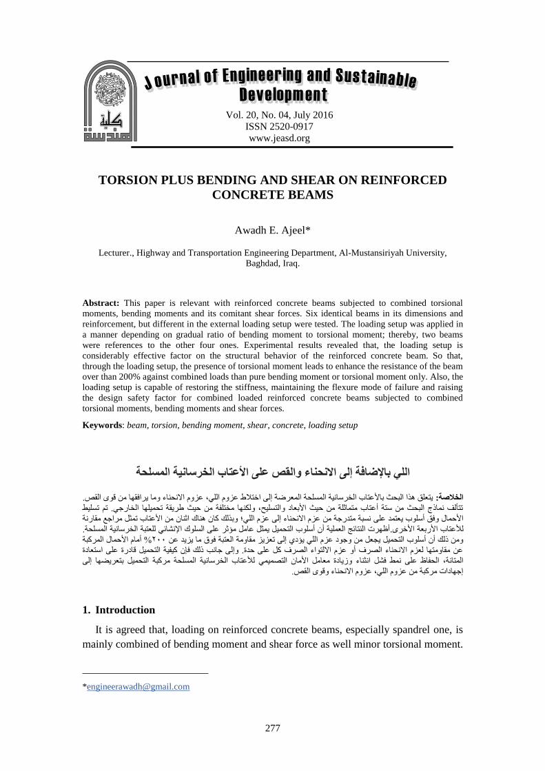
4.4. Failure Mode
At early stage of test, the beams were deformed by rotations and deflections but
without cracking, after that cracking appeared and propagated gradually. Near failure,
the cracks developed rapidly up to loading from the testing machine dropped. Pure
flexural beam (λ = ∞) failed by vertical crack extended vertically in the middle of the
beam while pure torsional beam (λ = 0) failed by diagonal cracks extended along the
entire beam. For the beam specimens subjected to combined torsion and bending,
diagonal cracks extended along the beam but the failure achieved by vertical crack in
the middle of the beam. Especially for beam specimen (B5) of (λ = 1.7) where the rate
of torsion is higher than the others, failure achieved in the middle of the beam but
with crushed concrete around the diagonal cracks in form of shear-compression
failure. The failure mode revealed that, for beams subjected to combined to bending
and torsional moments, the loading setup is effective in the failure mode and when (λ
≥ 1.7) the bending moment is dominant. Cracking of the tested beams at failure is
photographed in Fig. 9.

Journal of Engineering and Sustainable Development, Vol. 20, No.04, July 2016 www.jeasd.org (ISSN 2520-0917)
286
Figure 9: Failure of the tested beams
5. Conclusions
The experimental results of the present work revealed that, the loading setup is an
effective parameter on the structural behavior of reinforced concrete beam subjected
to torsion moment in addition to bending and shear stresses.
Diverging the concentric points load in the beam middle zone in order to decrease
bending moment/torsional moment (λ) value, lead to enhance the beam resistance to
combined torsion, bending and shear over than 200%.
The experimental results dispersion trends around theoretical curves in the
interaction diagrams of reinforced concrete beams subjected to combined torsion,
bending and shear are considerably dependent on loading setup.
Despite the stiffness of beam subjected to pure flexure or pure torsion only is better
than one when it is subjected to combined flexure and torsion, decreasing (λ) value
decreases deflections and twisting angles. So, loss of beam stiffness can be restored.
In the present study, the loading setup revealed that the structural behavior of the
reinforced concrete beam can be improved by increasing the torsional moment ratio
up to (λ ≥ 1.7) where the bending moment is dominant. Further work with increased
torsional moment to attain (λ < 1.7) is suggested to investigate the structural behavior
and especially failure warranty of combined loaded reinforced concrete beams
Abbreviations
f'c Cylindrical Compressive strength of concrete
fr Tensile strength of concrete.
fy Yielding stress of reinforcing steel
fu Ultimate strength of reinforcing steel
Pu Resultant strength of beam-specimen
Pu₀ Resultant strength of reference beam
V Shear strength of beam-specimen
V₀ Shear strength of reference beam

Journal of Engineering and Sustainable Development, Vol. 20, No.04, July 2016 www.jeasd.org (ISSN 2520-0917)
287
M Flexural strength of beam-specimen
M₀ Flexural strength of reference beam
T Torsional strength of beam-specimen
T₀ Torsional strength of reference beam
λ Ratio of applied bending moment / torsional moment
Δ Midspan deflection due to bending moment
Ф Angle of twist due to torsional moment at the beam ends
Ø Diameter of reinforcing steel
Acknowledgement
The researcher is glad to express his appreciation and thanks for the structural
engineering laboratory staff and the brotherly spirit technician (Akram Hasan
Hussein).
6. References
1. Kamiński, M. And Pawlak, W. (2011), "Load Capacity and Stiffness of Angular
Cross Section Reinforced Concrete Beams under Torsion", Archives of Civil and
Mechanical Engineering, Vol. 11, No. 4, pp. 885-903.
2. Elfgern, L. (1972), "Reinforced Concrete Beam Loaded in Combined Torsion,
Bending and Shear", 2nd
Edition, Department of Concrete Structures, Chalmers
University of Technology, Göteborg, No. 71:3, 230 p.
3. Cowan, H. J. and Armstrong, S. (1952), "Reinforced Concrete in Combined
Bending and Torsion", IABSE Congress Report, Swiss, Vol. 4, pp. 861-870.
4. Raut, L. L., and Kulkarni, D. B. (2014), "Torsional Strengthening of under
Reinforced Concrete Beams Using Crimped Steel Fiber", International Journal of
Research in Engineering and Technology, Vol. 3, No. 6, pp. 466-471.
5. Dakhel, R. H. (2012), "Effect of the Use of Steel Fibers and Self-Compacting
Concrete on the Behavior of Reinforced Concrete Beams Subjected to Pure
Torsion", M.Sc. Thesis, Civil Engineering Department, College of Engineering,
Al-Mustansiriyah University, Baghdad, Iraq, 80 p.
6. Abduljalil, B. S., Aziz, A. H. and Muhsen, I. Kh. (2012), "Strengthening of
Reinforced Concrete Beams under Combined Torsion and Bending Using Carbon
Fiber Reinforced Polymer Strips", The Iraqi Journal for Mechanical and Material
Engineering, Vol. 12, No. 4, pp. 754-769.
7. Avinash,S. P. and Parekar, R. S. (2010), "Steel Fiber Reinforced Concrete Beams
under Combined Torsion-Bending-Shear", Journal of Civil Engineering (IEB),
Vol. 38, No. 1, pp. 31-38.
8. Talaeitaba, S. B. and Mostofinejad, D. (2011), "Fixed Supports in Assessment of
RC Beams’ Behavior under Combined Shear and Torsion", International Journal
of Applied Science and Technology, Vol. 1 No. 5, pp. 119-126.
9. Tahmazian, B. (1969), "Torsion-Bending-Effort Trenchant a Rectangular
Reinforced Concrete Beam", Cited by [2].

Journal of Engineering and Sustainable Development, Vol. 20, No.04, July 2016 www.jeasd.org (ISSN 2520-0917)
288
10. Higazy, E. M. and El-Kateb, M. (2011), "Strengthening of Reinforced Concrete
Beams under Torsion Using CFRP Sheets", 36th
Conference on Our World in
Concrete & Structures, Singapore, 9 p.
11. Mohammad, K. I. and Al-Sulayfani, B. J. (2013), "Torsional Strengthening of RC
Beams with CFRP Wrap", Tikrit Journal of Engineering Sciences, Vol. 20, No. 3,
pp. 1-9.
12. Abduljalil, B. S. and Sarsam, K. F. (2012), "Torsional Behavior of Reinforced
Concrete T Beams Strengthened with CFRP Strips", Eng. & Tech. Journal, Vol.
30, No. 9, pp. 1462- 1482.
13. Mahmood, M. N. and Mahmood, A. Sh. (2011), "Torsional Behavior of
Prestressed Concrete Beams Strengthened with CFRP Sheets", 16th
International
Conference on Composite Structures, Porto, 12 p.
14. Jariwalaa, V. H., Patelb, P. V. and Purohi, S. P. (2012), "Strengthening of RC
Beams subjected to Combined Torsion and Bending with GFRP Composites",
Chemical, Civil and Mechanical Engineering Tracks of 3rd
Nirma University
International Conference on Engineering (NUiCONE 2012), 8 p.
15. Tudu, C. (2012), "Study of Torsional Behavior of Rectangular Reinforced
Concrete Beams Warpped with GFRP", M.Sc. Thesis, Department of Civil
Engineering, National Institute of Technology, Rourkela, Odisha, India, 108 p.
16. Panchacharam, S. and Belarbi, A. (2002), "Torsional Behavior of Reinforced
Concrete Beams Strengthened with FRP Composites", First FIB Congress, Osaka,
Japan, 11 p.
17. El-Awady, E., Husain, M. and Mandour, S. (2013), "FRP-Reinforced Concrete
Beams under Combined Torsion and Flexure", International Journal of
Engineering Science and Innovative Technology (IJESIT), Vol. 2, No. 1, pp. 384-
393.
18. ACI Code 318M-14, (2014), "Building Code Requirements for Structural
Concrete and Commentary", American Concrete Institute, September, 524 p.
19. Iraqi Specification, No.5 (1984), "Portland Cement", Central Organization
Standardization & Quality Control (C.O.S.Q.C.), Baghdad, Iraq.
20. Iraqi Specification, No.45 (1984), "Aggregates from Natural Sources for Concrete
and Construction", Central Organization Standardization & Quality Control
(C.O.S.Q.C.), Baghdad, Iraq.
21. Iraqi Specification, No.209 (1999), "Carbon Steel Bars for the Reinforcement of
Concrete", Central Organization Standardization & Quality Control (C.O.S.Q.C.),
Baghdad, Iraq.
22. ASTM C39/C39M (2016), "Standard Test Method for Compressive Strength of
Cylindrical Concrete Specimens", American Society for Testing and
Materials, 7 p.
23. ASTM C78/C78M (2016), "Standard Test Method for Flexural Strength of
Concrete (Using Simple Beam with Third-Point Loading)", American Society for
Testing and Materials, 4 p.