Embed Size (px)
Citation preview
These instructions must be left with the user
Installation Guide
Torsion Hinged Door
Jan 2017 1281732-A02-A1 G005-00

1281732-A02-A Jan 20172
Note! If being installed as part of an enclosure, please refer to the Side Panel Installation Instructions (document # 1283038-A02).
3Jan 2017 1281732-A02-A
Safety Information1.
Ensure the door is undamaged and no parts are missing.Ensure the panel size is suitable for the installation. Tempered glass cannot be cut.The wall retainers must be installed onto a waterproof, vertical and flat wall surface.Failure to do so will result in an unsatisfactory seal, which may cause property damage.The wall inclination (out-of-squareness) is should be out by no more than ±4mm/m.It is the responsibility of the INSTALLER to ensure that the installation complies withcouncil and/or local authority bylaws.Instructions, drawings and diagrams contained in this manual present informationavailable at the time of printing. Although every attempt has been made to keep themup-to-date, KOHLER reserves the right to implement product changes withoutfuther notice.
2.
3.4.5.
1.2.3
4.
5.
Attention
GENERAL INFORMATION
INTRODUCTION
future reference.
General1.2.3.4.
Care should be taken to avoid hidden pipes or wires when drilling into walls and floors.
We recommend that the unit is installed by a qualified shower installer or plumber.
Note!
TOOLS REQUIRED
3.0 mm6.0 mm
2.0 mm 2.5 mm 5.0 mm
#1square
drive
41281732-A02-A Jan 2017
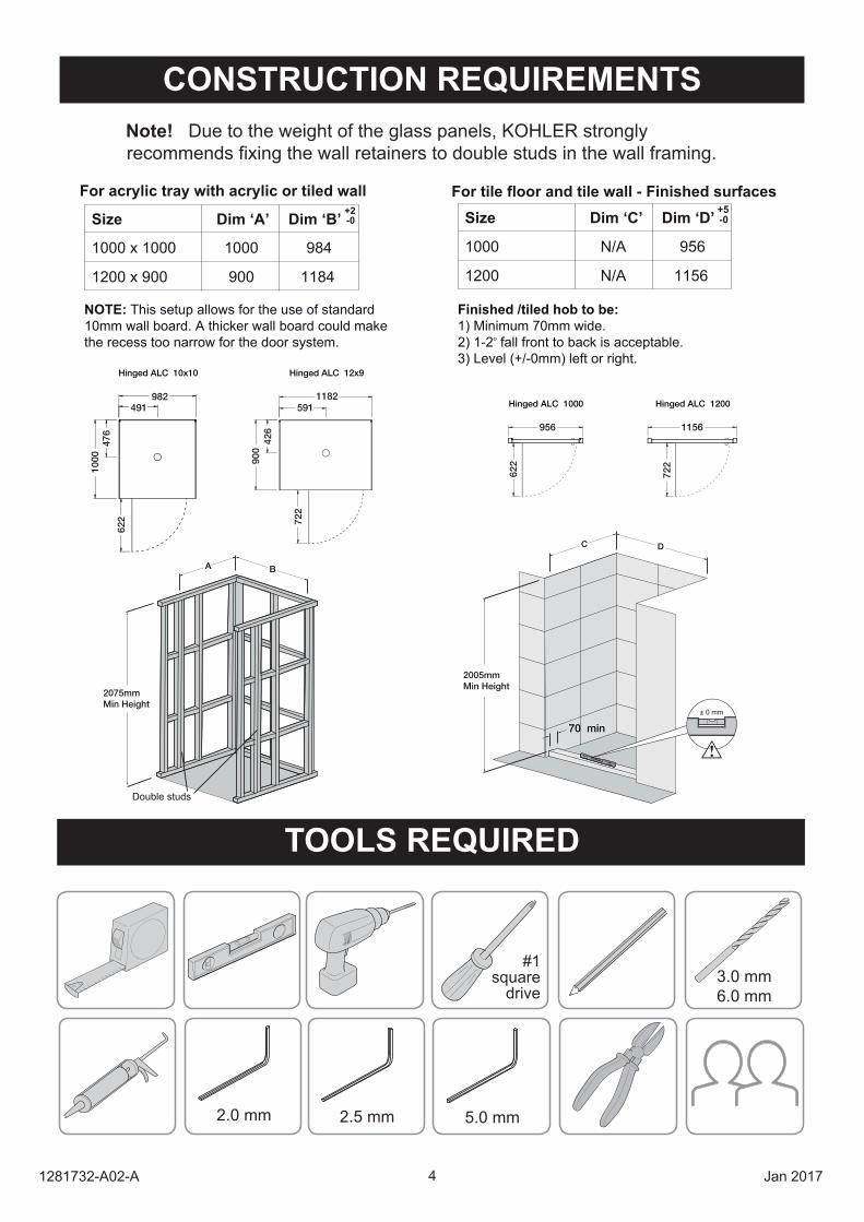
CONSTRUCTION REQUIREMENTS Due to the weight of the glass panels, KOHLER stronglyrecommends fixing the wall retainers to double studs in the wall framing.
Size
For acrylic tray with acrylic or tiled wall For tile floor and tile wall - Finished surfaces
Dim ‘A’
1000 x 1000 1000
Dim ‘B’ +2-0
984
1200 x 900 900 1184
Size Dim ‘C’
1000 N/A
Dim ‘D’ +5-0
956
1200 N/A 1156
NOTE: This setup allows for the use of standard 10mm wall board. A thicker wall board could make the recess too narrow for the door system.
Finished /tiled hob to be: 1) Minimum 70mm wide.2) 1-2o fall front to back is acceptable.3) Level (+/-0mm) left or right.
956 1156
722
Hinged ALC 1000 Hinged ALC 1200
622
1182591
900
722
426
Hinged ALC 10x10 Hinged ALC 12x9
982491
1000
622
476
C D
70 min
± 0 mm
2005mmMin Height
Double studs
A B
2075mmMin Height
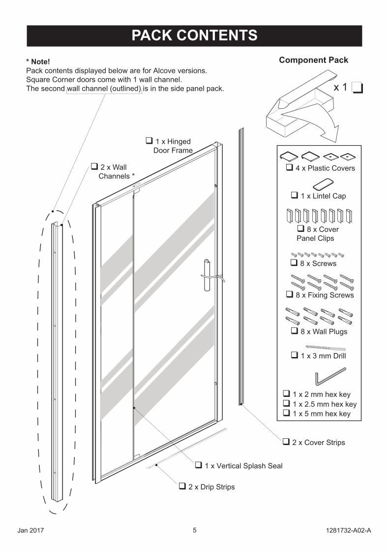
2 x WallChannels *
1 x HingedDoor Frame
PACK CONTENTS
1 x 2 mm hex key
1 x 5 mm hex key 1 x 2.5 mm hex key
5Jan 2017 1281732-A02-A
* Note! Pack contents displayed below are for Alcove versions.Square Corner doors come with 1 wall channel.The second wall channel (outlined) is in the side panel pack.
8 x Wall Plugs
8 x Fixing Screws
4 x Plastic Covers
1 x 3 mm Drill
8 x Cover Panel Clips
Component Pack
x 1
8 x Screws
1 x Lintel Cap
2 x Cover Strips
2 x Drip Strips
1 x Vertical Splash Seal
61281732-A02-A Jan 2017
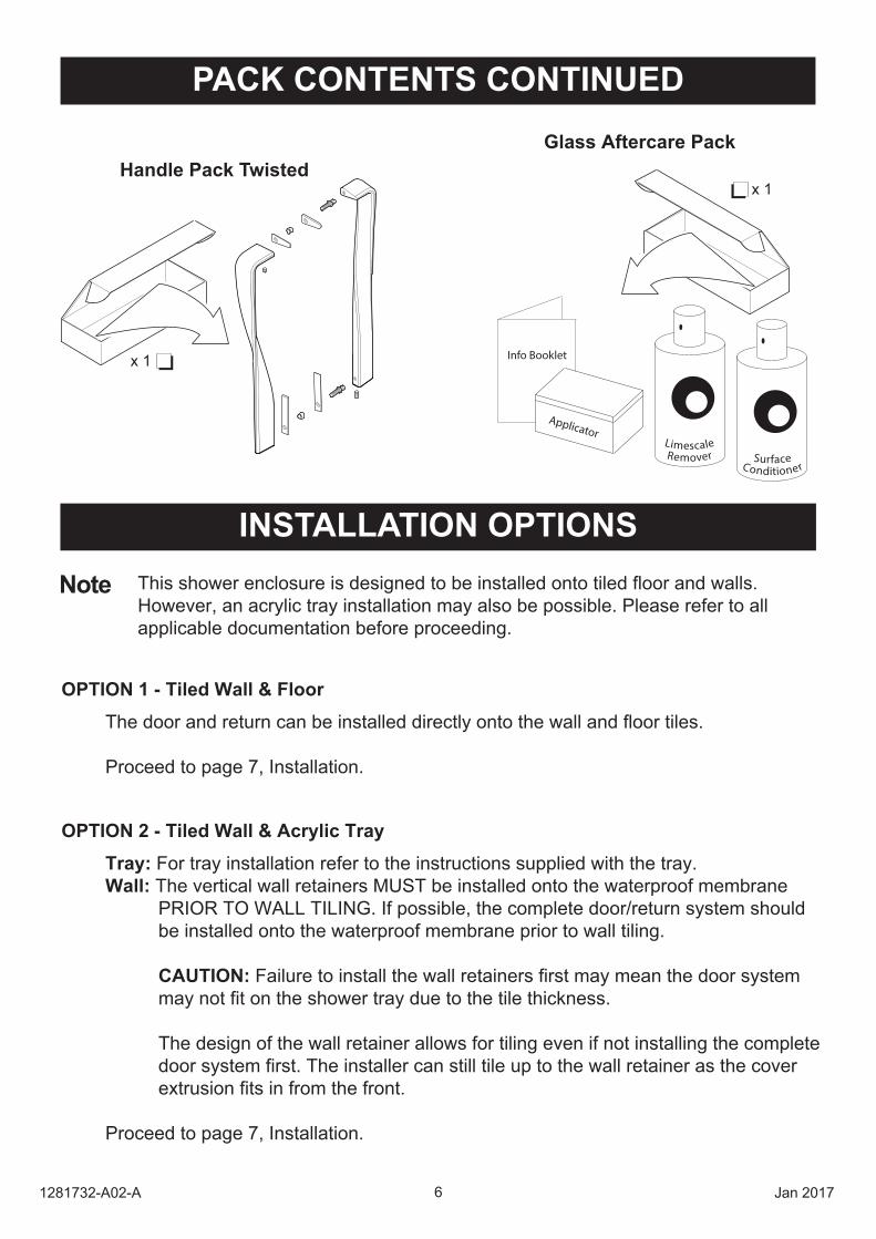
PACK CONTENTS CONTINUED
INSTALLATION OPTIONSThis shower enclosure is designed to be installed onto tiled floor and walls.However, an acrylic tray installation may also be possible. Please refer to allapplicable documentation before proceeding.
Tray: For tray installation refer to the instructions supplied with the tray.Wall: The vertical wall retainers MUST be installed onto the waterproof membrane PRIOR TO WALL TILING. If possible, the complete door/return system should be installed onto the waterproof membrane prior to wall tiling. CAUTION: Failure to install the wall retainers first may mean the door system may not fit on the shower tray due to the tile thickness.
The design of the wall retainer allows for tiling even if not installing the complete door system first. The installer can still tile up to the wall retainer as the cover extrusion fits in from the front.
Proceed to page 7, Installation.
OPTION 2 - Tiled Wall & Acrylic Tray
Note
The door and return can be installed directly onto the wall and floor tiles.
Proceed to page 7, Installation.
OPTION 1 - Tiled Wall & Floor
Handle Pack TwistedGlass Aftercare Pack
x 1
x 1
Info Booklet
Applicator
ConditionerSurfaceRemover
Limescale
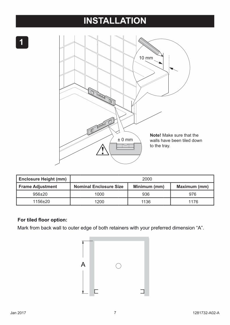
INSTALLATION
1
± 0 mm
10 mm
Note! Make sure that the walls ha e been tiled down to the tra .
Enclosure Height (mm) 2000
Frame Adjustment Nominal Enclosure Size Minimum (mm) Maximum (mm)
1000 936 976956±20
1156±20 1200 1136 1176
7Jan 2017 1281732-A02-A
For tiled floor option: Mark from back wall to outer edge of both retainers with your preferred dimension “A”.
A
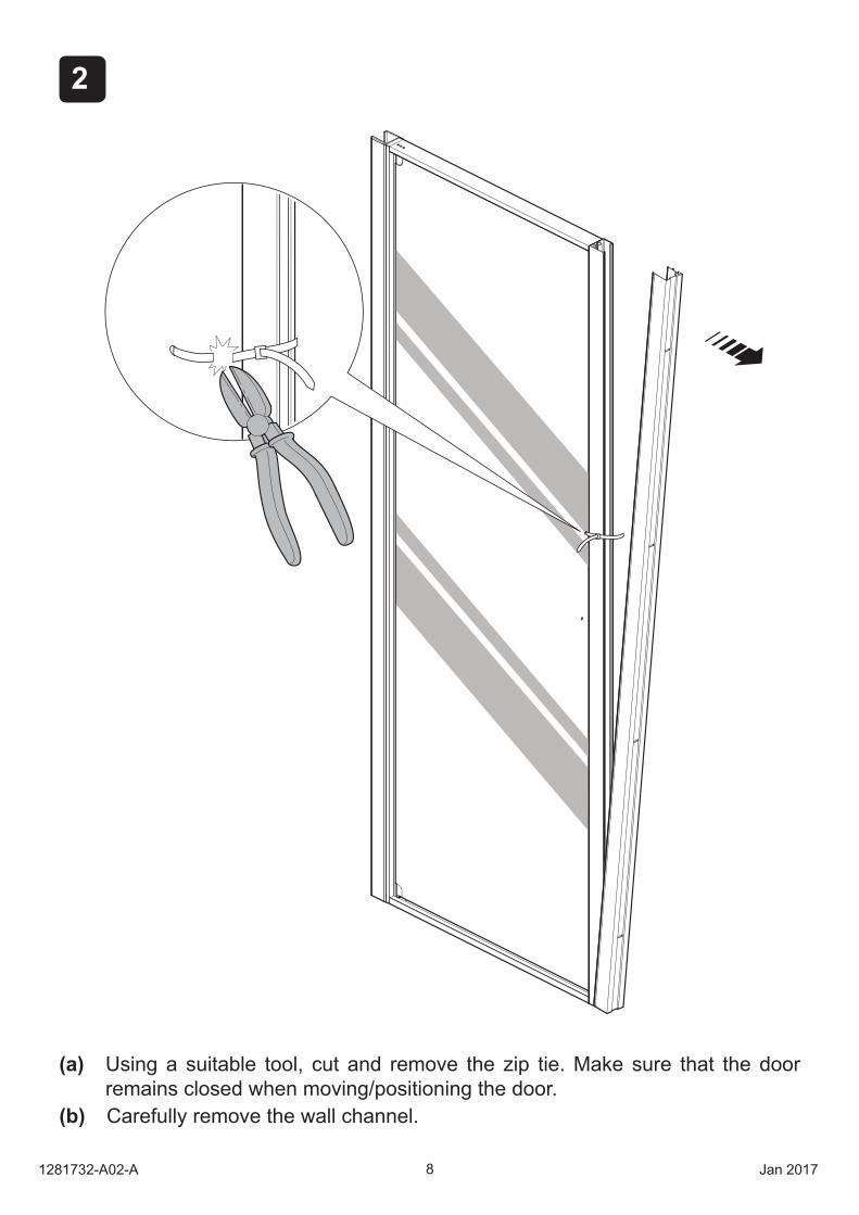
(a) Using a suitable tool cut and remo e the ip tie. Make sure that the door remains closed when mo ing/positioning the door.
(b)
2
81281732-A02-A Jan 2017
Carefully remove the wall channel.
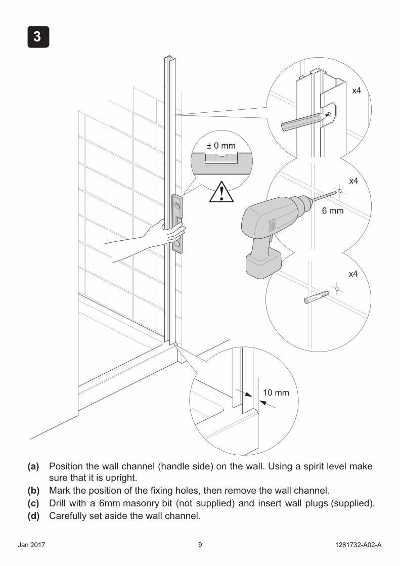
(a) Position the wall channel handle side on the wall. Using a spirit le el make sure that it is upright.
(b) Mark the position of the xing holes then remo e the wall channel.(c) Drill with a 6mm masonry bit (not supplied) and insert wall plugs (supplied).(d) Carefully set aside the wall channel.
3
9Jan 2017 1281732-A02-A
10 mm
± 0 mm
6 mm
x4
x4
x4
4
101281732-A02-A Jan 2017
± 0 mm6 mm
x4
x4
x4
10 mm
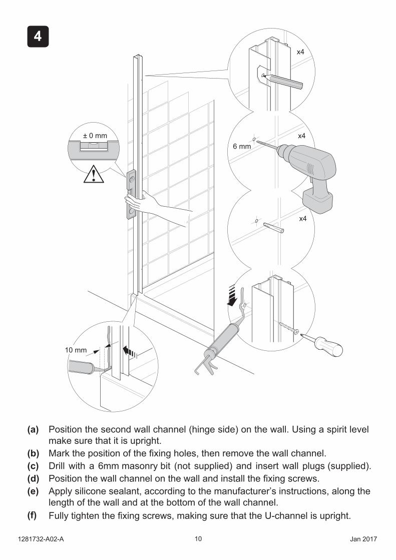
(a) Position the second wall channel (hinge side) on the wall. Using a spirit le el make sure that it is upright.
(b) Mark the position of the xing holes then remo e the wall channel.(c) Drill with a 6mm masonry bit (not supplied) and insert wall plugs (supplied).(d) Position the wall channel on the wall and install the
(f)
Apply silicone sealant, according to the manufacturer’s instructions, along the length of the wall and at the bottom of the wall channel.
xing screws.(e)
ull tighten the xing screws making sure that the U-channel is upright.
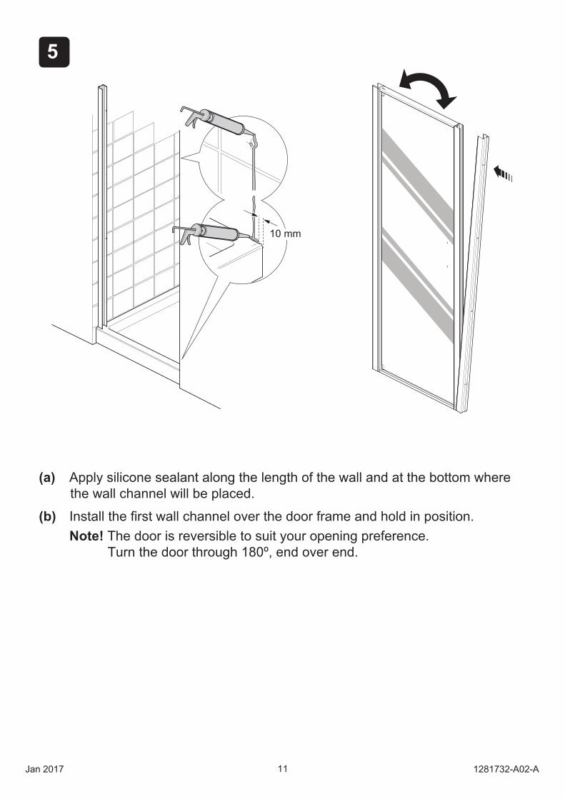
(b) Install the Note! The door is reversible to suit your opening preference. Turn the door through 180º, end over end.
rst wall channel o er the door frame and hold in position.
(a) Apply silicone sealant along the length of the wall and at the bottom where the wall channel will be placed.
5
11Jan 2017 1281732-A02-A
10 mm
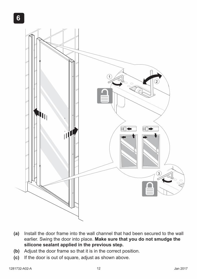
(a) Install the door frame into the wall channel that had been secured to the wall earlier. Swing the door into place. Make sure that you do not smudge thesilicone sealant applied in the previous step.
(b) Adjust the door frame so that it is in the correct position. If the door is out of square, adjust as shown above.(c)
6
121281732-A02-A Jan 2017
21
3
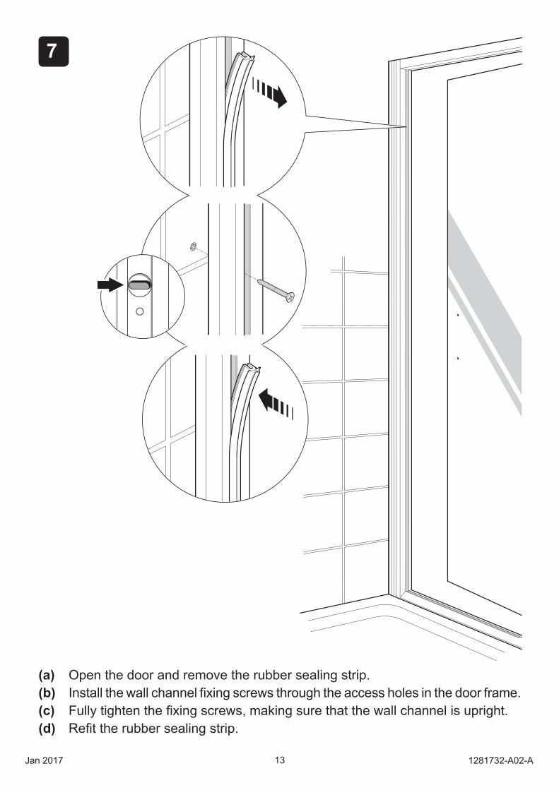
(a) pen the door and remo e the rubber sealing strip.(b) Install the wall channel xing screws through the access holes in the door frame.(c) ull tighten the xing screws making sure that the wall channel is upright.(d) e t the rubber sealing strip.
57
13Jan 2017 1281732-A02-A
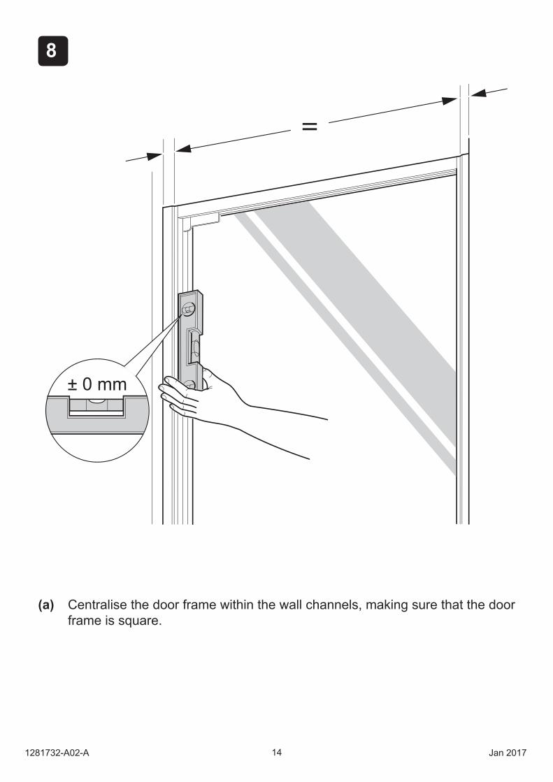
(a) Centralise the door frame within the wall channels, making sure that the door frame is s uare.
58
± 0 mm
141281732-A02-A Jan 2017
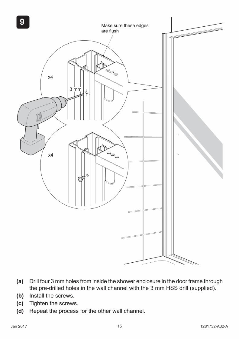
(a) Drill four 3 mm holes from inside the shower enclosure in the door frame through the pre-drilled holes in the wall channel with the 3 mm HSS drill (supplied).
(b) Install the screws.(c) Tighten the screws.(d) epeat the process for the other wall channel.
59
3 mm
x4
x4
Make sure these edges are ush
15Jan 2017 1281732-A02-A
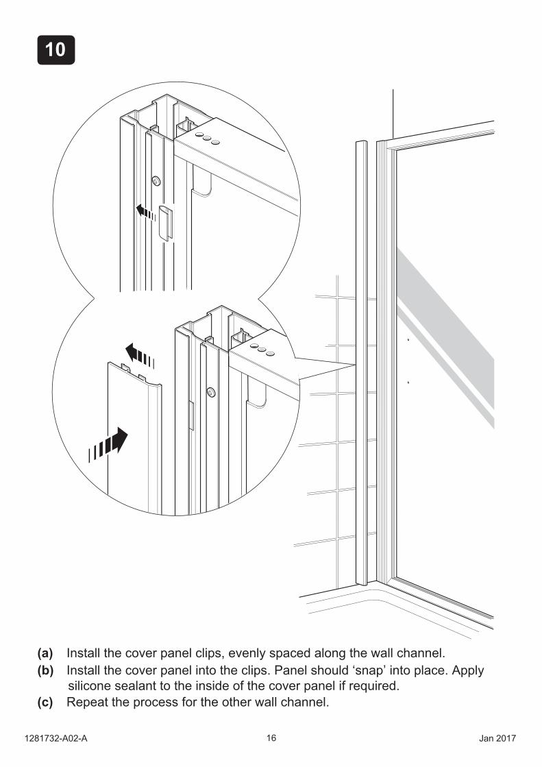
(a) Install the co er panel clips, evenly spaced along the wall channel.(b) Install the cover panel into the clips. Panel should ‘snap’ into place. Apply
silicone sealant to the inside of the cover panel if required.(c) Repeat the process for the other wall channel.
510
161281732-A02-A Jan 2017
511
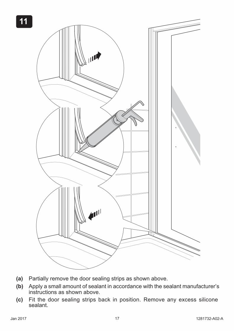
(a) Partiall remo e the door sealing strips as shown abo e.(b) Appl a small amount of sealant in accordance with the sealant manufacturer’s
instructions as shown abo e.(c) it the door sealing strips back in position. emo e an excess silicone
sealant.
17Jan 2017 1281732-A02-A
512
181281732-A02-A Jan 2017
a
b
c
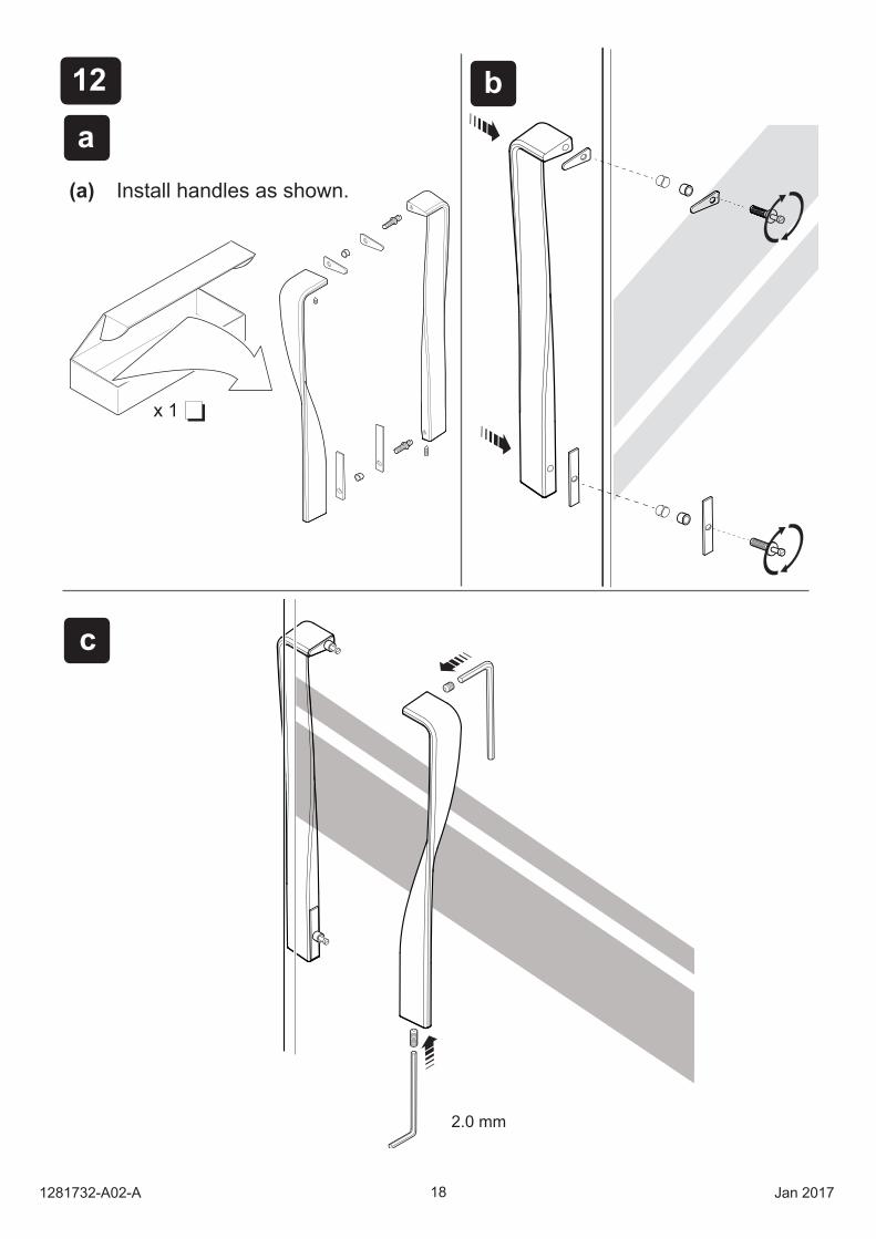
x 1
2.0 mm
(a) Install handles as shown.
513
19Jan 2017 1281732-A02-A
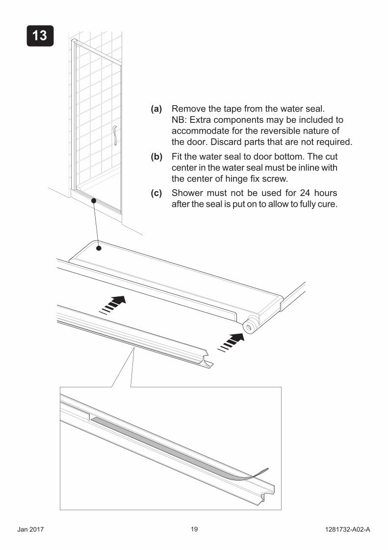
(a) Remove the tape from the water seal.NB: Extra components may be included toaccommodate for the reversible nature ofthe door. Discard parts that are not required.
(b) Fit the water seal to door bottom. The cut center in the water seal must be inline with
(c) Shower must not be used for 24 hours after the seal is put on to allow to fully cure.
514
1
2
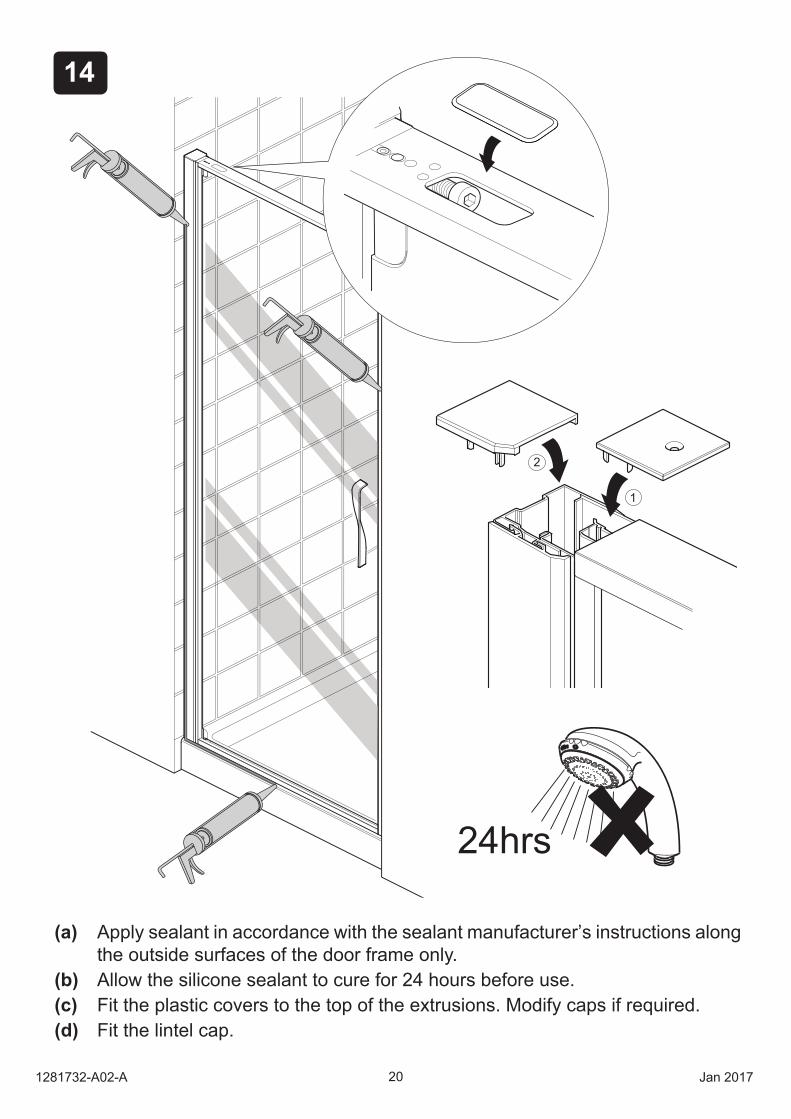
(a) Appl sealant in accordance with the sealant manufacturer’s instructions along the outside surfaces of the door frame onl .
(b) Allow the silicone sealant to cure for 24 hours before use.(c) it the plastic co ers to the top of the extrusions. Modify caps if required.(d) it the lintel cap.
24hrs
201281732-A02-A Jan 2017
515
516
21Jan 2017 1281732-A02-A
21
3
(a)
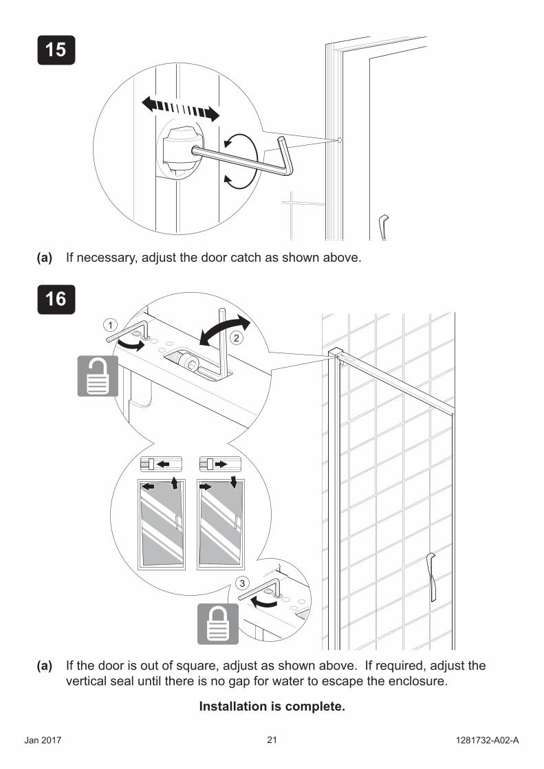
(a) If the door is out of square, adjust as shown above. If required, adjust thevertical seal until there is no gap for water to escape the enclosure.
Installation is complete.
21
3
If necessary, adjust the door catch as shown above.
221281732-A02-A Jan 2017
SPARE PARTS
CALL US FOR HELP
NEW ZEALAND AUSTRALIAKOHLER NZ LTD KOHLER CO.Free Ph: 0800 564 537 (0800 KOHLER) Free Ph: 1 800 KOHLERFree Fax: 0800 664 488 (1 800 564 537)www.kohler.co.nz www.au.kohler.com
For spare parts & warranty information, please visit our website:
Australiawww.au.kohler.com
New Zealandwww.kohler.co.nz
CONTACT AND WARRANTY INFORMATION
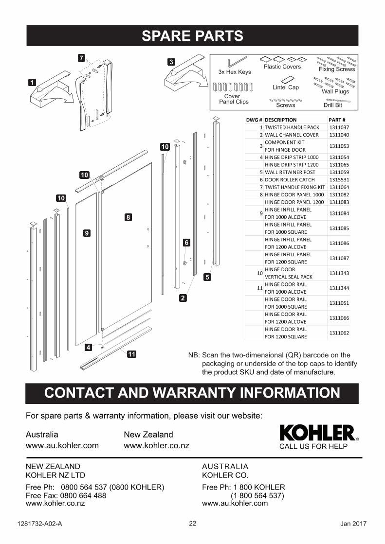
NB: Scan the two-dimensional (QR) barcode on the packaging or underside of the top caps to identify the product SKU and date of manufacture.
Wall Plugs
Fixing ScrewsPlastic Covers
Drill Bit
3x Hex Keys
Cover Panel Clips Screws
Lintel Cap
37
1
8
9
2
10
10
10
114
5
6
DWG # DESCRIPTION PART #1 TWISTED HANDLE PACK 13110372 WALL CHANNEL COVER 1311040
3COMPONENT KITFOR HINGE DOOR
1311053
4 HINGE DRIP STRIP 1000 1311054HINGE DRIP STRIP 1200 1311065
5 WALL RETAINER POST 13110596 DOOR ROLLER CATCH 13155317 TWIST HANDLE FIXING KIT 13110648 HINGE DOOR PANEL 1000 1311082
HINGE DOOR PANEL 1200 1311083
9HINGE INFILL PANELFOR 1000 ALCOVE
1311084
HINGE INFILL PANELFOR 1000 SQUARE
1311085
HINGE INFILL PANELFOR 1200 ALCOVE
1311086
HINGE INFILL PANELFOR 1200 SQUARE
1311087
10HINGE DOORVERTICAL SEAL PACK
1311343
11HINGE DOOR RAILFOR 1000 ALCOVE
1311344
HINGE DOOR RAILFOR 1000 SQUARE
1311051
HINGE DOOR RAILFOR 1200 ALCOVE
1311066
HINGE DOOR RAILFOR 1200 SQUARE
1311062