Embed Size (px)
Citation preview

PENGO RevTrak Manual �
TORQUE MONITORING and RECORDING SYSTEM
OWNER’S & OPERATOR’SMANUAL
800-599-02�� l www.pengoattachments.com l PENGO: 500 East Highway �0, Laurens, IA 50554, USA
Owner’s ManualParts ManualSafety PrecautionsOperating Instructions
Manual ID: RevTrak Manual.inddRelease Date: January ��, 20��
Printed in the USA
RevTrak™ system is designed specifically for use with Pengo® Revolution™ series Anchor Drives.

2 PENGO RevTrak Manual
PREFACE
This manual is used to familiarize you with safety, assembly, operation, adjustment, troubleshooting, and maintenance. Read and follow the recommendations in this manual to ensure safe and efficient operation. Keep this manual with the product at all times for future reference.
We want you to be completely satisfied with your new product, feel free to contact your local Authorized Service Dealer for help with service, replacement parts, or any other information you may require. If you need assistance in locating a dealer, visit our web site at www.pengoattachments.com or call customer service at 1-800-599-0211.
The descriptions and specifications in this manual are subject to change without notice. Pengo® reserves the right to improve products. Some product improvements may have taken place after this manual was printed. For the latest information on Pengo® products, visit our web site at www.pengoattachments.com or call customer service at 1-800-599-0211.
Thank you for buying and using Pengo® products!
Preface / Table of Contents ................................................................................................................................. 2Safety Statements ............................................................................................................................................ 3General Precautions ........................................................................................................................................... 4General Precautions Cont. .................................................................................................................................. 5Product Introduction ........................................................................................................................................... 6Troubleshooting ............................................................................................................................................ 7Component Identification ..................................................................................................................................... 8Component Identification / Function ................................................................................................................... 9RevTrak Display Set-Up .................................................................................................................................... �0RevTrak Display Set-Up Cont. ...........................................................................................................................��Anchor Drive Set-Up (RS-7 / 7X) ...................................................................................................................... �2Anchor Drive Set-Up (RS-7 / 7X) Cont. .............................................................................................................. �3Anchor Drive Set-Up (RS-�2) ............................................................................................................................ �4Anchor Drive Set-Up (RS-�2) Cont. ................................................................................................................... �5Anchor Drive Set-Up (RT, Two Speed Models) .................................................................................................. �6Anchor Drive Set-Up (RT, Two Speed Models) Cont. ........................................................................................ �7Anchor Drive Set-Up (RV, Variable Speed Models) ........................................................................................... �8Anchor Drive Set-Up (RV, Variable Speed Models) Cont. .................................................................................. �9RevTrak Operation .......................................................................................................................................... 20RevTrak Operation .......................................................................................................................................... 2�RevTrak Operation .......................................................................................................................................... 22RevTrak Data Charting (Raw Data) ................................................................................................................... 23RevTrak Data Charting (Customized Data) ....................................................................................................... 24RevTrak Data Charting (Bar Chart Data) .......................................................................................................... 25Display Layout (Main Display) ............................................................................................................................ 26Display Layout (Model Selection Display) ......................................................................................................... 27Display Layout (Custom � and 2 Display) ......................................................................................................... 28Display Layout (Main Menu and System Menu Display) ................................................................................... 29Display Layout (Lighting Adjustment and Time / Date Display) ......................................................................... 30Warranty Policy / Returned Goods Policy ......................................................................................................... 3�
TABLE OF CONTENTS

PENGO RevTrak Manual 3
ThIS STATEMENT IS USED whERE SERIOUS INjURY OR DEATh wILL RESULT IF ThE INSTRUCTIONS ARE NOT FOLLOwED PROPERLY.
ThIS STATEMENT IS USED whERE SERIOUS INjURY OR DEATh COULD RESULT IF ThE INSTRUCTIONS ARE NOT FOLLOwED PROPERLY.
ThIS STATEMENT IS USED whERE MINOR INjURY COULD RESULT IF ThE INSTRUCTIONS ARE NOT FOLLOwED PROPERLY.
ThIS SYMBOL BY ITSELF OR USED wITh A SAFETY SIGNAL wORD ThROUGhOUT ThIS MANUAL IS USED TO CALL YOUR ATTENTION TO INSTRUCTIONS INvOLvING YOUR PERSONAL SAFETY OR ThE SAFETY OF OThERS. FAILURE TO FOLLOw ThESE INSTRUCTIONS CAN RESULT IN INjURY OR DEATh.
READ MANUAL PRIOR TO INSTALLImproper installation, operation, or maintenance of the equipment could result in serious injury or death. Operators and maintenance personnel should read this manual as well as all manuals related to this equipment. FOLLOw ALL SAFETY INSTRUCTIONS IN ThIS MANUAL.
READ AND UNDERSTAND ALL SAFETY STATEMENTSRead all safety decals and safety statements in all manuals prior to operating or working on this equipment. Know and obey all OSHA regulations, local laws and other professional guidelines for your operation. Know and follow good work practices when assembling, maintaining, repairing, mounting, removing or operating this equipment.
KNOw YOUR EQUIPMENTKnow your equipment’s capabilities, dimensions and operations before operating. Visually inspect your equipment before you start, and never operate equipment that is not in proper working order with all safety devices intact. Check all hardware to assure it is tight. Make certain that all locking pins, latches, and connection devices are properly installed and secured. Remove and replace any damaged, fatigued or excessively worn parts. Make certain all safety decals are in place and are legible. Keep decals clean, and replace them if they become worn and hard to read.
DO NOT MODIFY EQUIPMENTModifications may weaken the integrity of the equipment and may impair the functions, safety, life, and performance of the equipment. When making repairs, use only the manufactures genuine parts, following authorized instructions. Other parts may be substandard in fit and quality.
DANGER
wARNING
CAUTION
wARNING
wARNING
SAFETY STATEMENTS
wARNING

4 PENGO RevTrak Manual
GENERAL PRECAUTIONS
PREPARE FOR EMERGENCIES• Be prepared if a fire starts.• Keep a first aid kit near by when operating equipment.
OPERATOR SAFETY• Protective clothing and equipment should be worn at all times.• Wear protective clothing and equipment appropriate for the job. Avoid loose fitting clothing.• Prolonged exposure to excessive noise can cause hearing loss. Wear suitable hearing protection such as ear plugs.• Operating equipment safely requires the full attention of the operator. Avoid distractions.• Never let a minor or inexperienced person operate the unit.
PRODUCT SAFETY• Inspect the entire product before operation.• Replace parts that are cracked, chipped or damaged in any way before operation.• Keep others away when making any adjustments to the unit.
PRACTICE SAFE MAINTENANCE• Use proper tools and equipment when conducting maintenance, refer to this manual for additional information.• Work in a clean dry area.• Inspect all parts. Be sure parts are in good working condition and installed properly.• Remove build up of grease, oil or any debris.• Remove all tools and unused parts from equipment before beginning operation.
BE ALERT ON ThE jOB SITETragic accidents can occur if the operator is not alert to the presence of children. Children are often attracted to machinery and work activity. Never assume that children will remain where you last saw them. BE ALERT and turn the equipment off if children enter the work area. Keep children out of the work area and under supervision of another responsible adult.
USE CARE wITh hYDRAULIC FLUID PRESSUREHydraulic fluid under pressure can penetrate the skin and cause serious injury or death. Hydraulic leaks under pressure may not be visible. Before connecting or disconnecting hydraulic hoses, read your prime mover’s operator’s manual for detailed instructions on connecting and disconnecting hydraulic hoses or fittings.
• Keep unprotected body parts, such as face, eyes, and arms as far away as possible from a suspected leak. Flesh injected with hydraulic fluid may develop gangrene or other permanent disabilities.• If injured by injected fluid, see a doctor at once. If your doctor is not familiar with this type of injury, ask him to research it immediately to determine proper treatment.• Wear safety glasses, protective clothing, and use a piece of cardboard or wood when searching for hydraulic leaks. DO NOT USE YOUR HANDS! SEE ILLUSTRATION.
CAUTION
wARNING
wARNING
wARNING

PENGO RevTrak Manual 5
GENERAL PRECAUTIONS - CONTINUED
LOwER OR SUPPORT RAISED EQUIPMENTDuring installation of the RevTrak system:
• Do not work under raised booms without supporting them. • Do not use support material made of concrete blocks, logs, buckets, barrels, or any other material that could suddenly collapse or shift positions.• Make sure support material is solid, not decayed, warped, twisted, or tapered. • Lower booms to ground level or on blocks. • Lower booms and attachments to the ground before leaving the cab or operator’s station.• Keep others away when making any adjustments to the unit.
wARNING
SAFETY DECALSThis unit comes equipped with all safety decals in place. They are designed to help you safely operate your unit. Read and follow all safety decals. • Keep all safety decals clean and legible at all times.• Replace safety decals that are missing or have become illegible.• Safety decals are available from your distributor or manufacture.• Some parts installed during repair may require safety decals to be affixed to the replacement part. When ordering the replacement part(s) be sure the correct safety decal(s) are included in your order.
INSTALLING SAFETY DECALS• Clean the desired area with warm soapy water.• Decide on exact position before you remove the backing paper.• Peel backing paper from decal. Press firmly on the surface.• Air pockets can be pierced with a pin and smoothed.
SAFETY DECAL INFORMATION
Figure �

6 PENGO RevTrak Manual
PRODUCT INTRODUCTION
The Pengo® RevTrak™ system is a electronic torque monitoring and data recording system developed for the helical pier/anchor industry. The RevTrak™ system is a pressure differential system that continuously monitors, records and displays the installation torque. As the pier/anchor is installed into the ground the RevTrak system will compute the torque based on the pre programmed specifications of the Revolution™ series Anchor Drives and the differential pressure reading.
The RevTrak™ system using pressure transducers will monitor the inlet pressure, outlet pressure and high/low speed pressure of the Planetary Anchor Drive to calculate the torque. The Pengo® Revolution™ series Anchor Drives are all configured with dedicated transducer ports on the hydraulic motor for accurate and easy installation. While the RevTrak™ system can be adapted to work with other types of Anchor Drives the system is designed specifically for use with the Pengo® Revolution™ series Anchor Drives. Additional hydraulic fittings and mounting brackets (not provided) maybe necessary when using the RevTrak™ system with other types of Anchor Drives. The RevTrak™ system is not recommended for use with other types of two speed Anchor Drives.
The RevTrak™ systems operator interface is unique in that it does not require any secondary software to operate. All operator interface is via a LC digital display that can be mounted easily inside the cab of the prime mover. During operation all installation data is recorded to a MMC/SD memory card. This nonvolatile memory card can store up to 2 GB of data allowing for weeks of installation history to be captured. The SD memory card is stored inside the data logger which is mounted on the same bracket as the Display unit. The RevTrak™ system uses CAN communication via electrical cables to communicate between the Planetary Anchor Drive and the Display unit.
All data recorded to the SD memory card can be exported to a PC using the supplied USB card reader. Once the data is exported to a PC the data can be analyzed and formatted using Microsoft® Excel. The time, date, Drive model, differential pressure and torque are all displayed once the data is exported into Excel.
TOLERANCES UNLESS OTHERWISE SPECIFIED.X .1 [2.54 .XX .03 [.76] .XXX .010 [.25] ANGLE 1 DEG.
LBS Kg0.00
TOP LEVEL
THIS DRAWING IS THE PROPERTY OF PENGO 500 E. HIGHWAY 10 LAURENS, IA. 50554. NO USE THEREOF SHALL BE MADE OTHER THAN AS A REFERENCE FOR PROPOSALS SUBMITTED BY PENGO CORPORATION AND/OR FOR JOBS BEING EXECUTED IN CONFORMITY WITH SUCH PROPOSALS HAVE BEEN ACCEPTED. UNLESS THE CONSENT OF SAID PENGO CORPORATION HAS BEEN PREVIOUSLY OBTAINED. NO PART OF THIS DRAWING SHALL BE COPPIED OR DUPLICATED OR IT'S CONTENTS DISCLOSED.
DRAWN BYMATERIAL
TITLE:
SIZE REV
SCALE: 1:1 SHEET 1 OF 1HEAT TREAT
THIRD ANGLE PROJECTION
B
DATECHECKED BY

PENGO RevTrak Manual 7
In the event your Pengo® RevTrak™ system malfunctions, please refer to the section below to identify the cause of the problem and possible remedy. If the problem persists, contact your Authorized Service Dealer for assistance.
NO POwER TO DISPLAY: • Bad wire harness connection. Check all connections to ensure proper and tight connections. • Auxiliary power adapter not connected. Check that auxiliary port connection is correct. • Blown fuse in the Display Wire Harness. Check fuse located inside the power adapter end. See below. • Faulty Secondary power cord connection. - Ensure the cord attached to the battery is correct (+ / -). - Blown fuse, replace fuse (7.5 amp fuse). SD CARD ISSUES: • Data will not record on SD card. - Remove the “Torque.csv” file from the SD card and retry. • Logger will not recognise SD card. - Ensure SD card is installed correctly (Arrow Down) - SD card is locked, slide lock tab back to unlock. - SD card is too large. SD carb must be 2GB or smaller in size. - SD card is not formatted correctly. FAT is correct format. - SD card is damaged, replace SD card with new. - SD card does not have CONFIG.CFG file pre-loaded. Reload file. - Damaged Logger. Replace logger if damage has occurred. FAULT MESSAGES: • Communication Fault. Faulty wire harness connection, check all connections. • Port A Transducer Fault. Faulty connection or faulty transducer, check or replace. • Port B Transducer Fault. Faulty connection or faulty transducer, check or replace. • Sequence Transducer Fault. Faulty connection or faulty transducer, check or replace. • Locked. SD card is missing or not formatted correctly. Ensure SD card is installed and formatted correctly.
DATA EXPORT: • Unable to open and read recorded data. Ensure the computer has Microsoft Excel installed. • Recorded data will not export to computer. - Ensure card reader is connected to the USB port correctly. - SD card is loose in the card reader, check connection. - Card reader is faulty. Card reader should have red light when connected to a USB port on a computer.
NO TORQUE OR PRESSURE READINGS AT DISPLAY: • Transducers not installed correctly. Ensure transducers are tight and wire harness connection is good. • Cables not connected or damaged. Check all cable connections and check for any damage or cuts.
TROUBLEShOOTING
Power Adapter Fuse Location Illustration
TOLERANCES UNLESS OTHERWISE SPECIFIED.X .1 [2.54 .XX .03 [.76] .XXX .010 [.25] ANGLE 1 DEG.
LBS Kg0.00
Figure 5B
THIS DRAWING IS THE PROPERTY OF PENGO 500 E. HIGHWAY 10 LAURENS, IA. 50554. NO USE THEREOF SHALL BE MADE OTHER THAN AS A REFERENCE FOR PROPOSALS SUBMITTED BY PENGO CORPORATION AND/OR FOR JOBS BEING EXECUTED IN CONFORMITY WITH SUCH PROPOSALS HAVE BEEN ACCEPTED. UNLESS THE CONSENT OF SAID PENGO CORPORATION HAS BEEN PREVIOUSLY OBTAINED. NO PART OF THIS DRAWING SHALL BE COPPIED OR DUPLICATED OR IT'S CONTENTS DISCLOSED.
DRAWN BYMATERIAL
TITLE:
SIZE REV
SCALE: 1:4 SHEET 1 OF 1HEAT TREAT
THIRD ANGLE PROJECTION
B
DATECHECKED BY
There is a 3 amp fuse located inside the power adapter housing.
If the Display does not have power, check the fuse located inside the power adapter end of the Display Harness.
Unscrew the tip portion of the power adapter to
expose fuse.

8 PENGO RevTrak Manual
COMPONENT IDENTIFICATION
Pengo continually looks for new ways to improve its products. Therefore, Pengo reserves the right to make changes to our products and specifications without notice.
Use the illustration below to help familiarize yourself with the various components and controls.ITEM PART No. QTY DESCRIPTION
� 6�02�4 � DISPLAY RM-1401 S02 [REVTRAK]2 6�02�5 � LOGGER CAN [REVTRAK]3 6�02�6 � CONTROLLER DVC7 [REVTRAK]4 6�02�7 � HARNESS WIRE-DRIVE [REVTRAK]5 6�02�8 � HARNESS WIRE-DISPLAY [REVTRAK]6 6�02�9 3 TRANSDUCER 5000 PSI [REVTRAK]7 6�0220 � CABLE 10’ SECTION [REVTRAK]8 6�022� � CABLE 20’ SECTION [REVTRAK]9 6�0222 � CLIP BRACKET LOGGER [REVTRAK]
�0 6�0300 � CARD MEMORY 2GB REVTRAK�� 6�0232 � BRACKET DISPLAY MNT PAINTED�2 6�0294 � CARD READER USB REVTRAK�3 6�0297 2 CUP SUCTION �.50 OD RUBBER�4* 6�0295 6 SCREW HEX SOC HD M4x�0 ZINC�5* 6�0296 2 NUT HEX M4�6 6�03�0 � CABLE SECONDARY POWER�7* �5�662 2 SCREW HEX HD �/4” X �-�/2”�8* �745�2 2 NUT HEX LOCK 1/4”�9* 260046 2 NUT HEX �0-24
LBS Kg1.13 0.51
610232
CHECKED BY DATEMJR
A
THIRD ANGLE PROJECTION
TOLERANCES UNLESS OTHERWISE SPECIFIED.X .1 [2.54 .XX .03 [.76] .XXX .010 [.25] ANGLE 1 DEG.
HEAT TREAT SHEET 1 OF 1
BRACKET, DISPLAY MOUNT (PAINTED)
EAM
SCALE: 1:2
REVSIZE
TITLE:
ASSEMBLYMATERIALDRAWN BY
THIS DRAWING IS THE PROPERTY OF PENGO 500 E. HIGHWAY 10 LAURENS, IA. 50554. NO USE THEREOF SHALL BE MADE OTHER THAN AS A REFERENCE FOR PROPOSALS SUBMITTED BY PENGO CORPORATION AND/OR FOR JOBS BEING EXECUTED IN CONFORMITY WITH SUCH PROPOSALS HAVE BEEN ACCEPTED. UNLESS THE CONSENT OF SAID PENGO CORPORATION HAS BEEN PREVIOUSLY OBTAINED. NO PART OF THIS DRAWING SHALL BE COPPIED OR DUPLICATED OR IT'S CONTENTS DISCLOSED.
NONE
08/20/09
11LBS Kg
0.00
THIS DRAWING IS THE PROPERTY OF PENGO 500 E. HIGHWAY 10 LAURENS, IA. 50554. NO USE THEREOF SHALL BE MADE OTHER THAN AS A REFERENCE FOR PROPOSALS SUBMITTED BY PENGO CORPORATION AND/OR FOR JOBS BEING EXECUTED IN CONFORMITY WITH SUCH PROPOSALS HAVE BEEN ACCEPTED. UNLESS THE CONSENT OF SAID PENGO CORPORATION HAS BEEN PREVIOUSLY OBTAINED. NO PART OF THIS DRAWING SHALL BE COPPIED OR DUPLICATED OR IT'S CONTENTS DISCLOSED.
DRAWN BYMATERIAL
TITLE:
SIZE REV
SCALE: 1:1
EAM
SHEET 1 OF 1HEAT TREAT
TOLERANCES UNLESS OTHERWISE SPECIFIED.X .1 [2.54 .XX .03 [.76] .XXX .010 [.25] ANGLE 1 DEG.
THIRD ANGLE PROJECTION
A
DATECHECKED BY
610294
12
LBS Kg0.00
THIS DRAWING IS THE PROPERTY OF PENGO 500 E. HIGHWAY 10 LAURENS, IA. 50554. NO USE THEREOF SHALL BE MADE OTHER THAN AS A REFERENCE FOR PROPOSALS SUBMITTED BY PENGO CORPORATION AND/OR FOR JOBS BEING EXECUTED IN CONFORMITY WITH SUCH PROPOSALS HAVE BEEN ACCEPTED. UNLESS THE CONSENT OF SAID PENGO CORPORATION HAS BEEN PREVIOUSLY OBTAINED. NO PART OF THIS DRAWING SHALL BE COPPIED OR DUPLICATED OR IT'S CONTENTS DISCLOSED.
DRAWN BYMATERIAL
TITLE:
SIZE REV
SCALE: 1:1
EAM
SHEET 1 OF 1HEAT TREAT
TOLERANCES UNLESS OTHERWISE SPECIFIED.X .1 [2.54 .XX .03 [.76] .XXX .010 [.25] ANGLE 1 DEG.
THIRD ANGLE PROJECTION
A
DATECHECKED BY
610297
13
LBS Kg0.00
610310
THIS DRAWING IS THE PROPERTY OF PENGO 500 E. HIGHWAY 10 LAURENS, IA. 50554. NO USE THEREOF SHALL BE MADE OTHER THAN AS A REFERENCE FOR PROPOSALS SUBMITTED BY PENGO CORPORATION AND/OR FOR JOBS BEING EXECUTED IN CONFORMITY WITH SUCH PROPOSALS HAVE BEEN ACCEPTED. UNLESS THE CONSENT OF SAID PENGO CORPORATION HAS BEEN PREVIOUSLY OBTAINED. NO PART OF THIS DRAWING SHALL BE COPIED OR DUPLICATED OR IT'S CONTENTS DISCLOSED.
DRAWN BY
MATERIAL
TITLE:
SIZE REV
SCALE: 1:2 SHEET 1 OF 1HEAT TREAT
TOLERANCES UNLESS OTHERWISE SPECIFIED.X .1 [2.54 .XX .03 [.76] .XXX .010 [.25] ANGLE 1 DEG.
THIRD ANGLE PROJECTION
C
DATECHECKED BY
C61
0310
REV
16
LBS Kg0.00
THIS DRAWING IS THE PROPERTY OF PENGO 500 E. HIGHWAY 10 LAURENS, IA. 50554. NO USE THEREOF SHALL BE MADE OTHER THAN AS A REFERENCE FOR PROPOSALS SUBMITTED BY PENGO CORPORATION AND/OR FOR JOBS BEING EXECUTED IN CONFORMITY WITH SUCH PROPOSALS HAVE BEEN ACCEPTED. UNLESS THE CONSENT OF SAID PENGO CORPORATION HAS BEEN PREVIOUSLY OBTAINED. NO PART OF THIS DRAWING SHALL BE COPPIED OR DUPLICATED OR IT'S CONTENTS DISCLOSED.
DRAWN BYMATERIAL
TITLE:
SIZE REV
SCALE: 2:1
EAM
SHEET 1 OF 1HEAT TREAT
TOLERANCES UNLESS OTHERWISE SPECIFIED.X .1 [2.54 .XX .03 [.76] .XXX .010 [.25] ANGLE 1 DEG.
THIRD ANGLE PROJECTION
A
DATECHECKED BY
610300
10
LBS Kg0.05 0.02
08/18/09
NONE
THIS DRAWING IS THE PROPERTY OF PENGO 500 E. HIGHWAY 10 LAURENS, IA. 50554. NO USE THEREOF SHALL BE MADE OTHER THAN AS A REFERENCE FOR PROPOSALS SUBMITTED BY PENGO CORPORATION AND/OR FOR JOBS BEING EXECUTED IN CONFORMITY WITH SUCH PROPOSALS HAVE BEEN ACCEPTED. UNLESS THE CONSENT OF SAID PENGO CORPORATION HAS BEEN PREVIOUSLY OBTAINED. NO PART OF THIS DRAWING SHALL BE COPPIED OR DUPLICATED OR IT'S CONTENTS DISCLOSED.
DRAWN BYMATERIAL STEEL
TITLE:
SIZE REV
SCALE: 1:2
EAM
CLIP BARCKET, LOGGER [TORQUE TRAK]
SHEET 1 OF 1HEAT TREAT
TOLERANCES UNLESS OTHERWISE SPECIFIED.X .1 [2.54 .XX .03 [.76] .XXX .010 [.25] ANGLE 1 DEG.
THIRD ANGLE PROJECTION
A
MJRDATECHECKED BY
610222
9
LBS Kg0.00
REV
6102
20D
610220
THIS DRAWING IS THE PROPERTY OF PENGO 500 E. HIGHWAY 10 LAURENS, IA. 50554. NO USE THEREOF SHALL BE MADE OTHER THAN AS A REFERENCE FOR PROPOSALS SUBMITTED BY PENGO CORPORATION AND/OR FOR JOBS BEING EXECUTED IN CONFORMITY WITH SUCH PROPOSALS HAVE BEEN ACCEPTED. UNLESS THE CONSENT OF SAID PENGO CORPORATION HAS BEEN PREVIOUSLY OBTAINED. NO PART OF THIS DRAWING SHALL BE COPPIED OR DUPLICATED OR IT'S CONTENTS DISCLOSED.
DRAWN BY
MATERIAL
TITLE:
SIZE REV
SCALE: 1:1
-
SHEET 1 OF 1HEAT TREAT
TOLERANCES UNLESS OTHERWISE SPECIFIED.X .1 [2.54 .XX .03 [.76] .XXX .010 [.25] ANGLE 1 DEG.
THIRD ANGLE PROJECTION
D
DATECHECKED BY
8
LBS Kg0.00
REV
6102
20D
610220
THIS DRAWING IS THE PROPERTY OF PENGO 500 E. HIGHWAY 10 LAURENS, IA. 50554. NO USE THEREOF SHALL BE MADE OTHER THAN AS A REFERENCE FOR PROPOSALS SUBMITTED BY PENGO CORPORATION AND/OR FOR JOBS BEING EXECUTED IN CONFORMITY WITH SUCH PROPOSALS HAVE BEEN ACCEPTED. UNLESS THE CONSENT OF SAID PENGO CORPORATION HAS BEEN PREVIOUSLY OBTAINED. NO PART OF THIS DRAWING SHALL BE COPPIED OR DUPLICATED OR IT'S CONTENTS DISCLOSED.
DRAWN BY
MATERIAL
TITLE:
SIZE REV
SCALE: 1:1
-
SHEET 1 OF 1HEAT TREAT
TOLERANCES UNLESS OTHERWISE SPECIFIED.X .1 [2.54 .XX .03 [.76] .XXX .010 [.25] ANGLE 1 DEG.
THIRD ANGLE PROJECTION
D
DATECHECKED BY
7
LBS Kg0.27 0.12
09/09/09
NONE
THIS DRAWING IS THE PROPERTY OF PENGO 500 E. HIGHWAY 10 LAURENS, IA. 50554. NO USE THEREOF SHALL BE MADE OTHER THAN AS A REFERENCE FOR PROPOSALS SUBMITTED BY PENGO CORPORATION AND/OR FOR JOBS BEING EXECUTED IN CONFORMITY WITH SUCH PROPOSALS HAVE BEEN ACCEPTED. UNLESS THE CONSENT OF SAID PENGO CORPORATION HAS BEEN PREVIOUSLY OBTAINED. NO PART OF THIS DRAWING SHALL BE COPPIED OR DUPLICATED OR IT'S CONTENTS DISCLOSED.
DRAWN BYMATERIAL STAINLESS STEEL
TITLE:
SIZE REV
SCALE: 1:1
EAM
TRANSDUCER, 5000 PSI [TORQUE TRAK]
SHEET 1 OF 1HEAT TREAT
TOLERANCES UNLESS OTHERWISE SPECIFIED.X .1 [2.54 .XX .03 [.76] .XXX .010 [.25] ANGLE 1 DEG.
THIRD ANGLE PROJECTION
A
MJRDATECHECKED BY
610219
6
LBS Kg0.00
REV
6102
18D
610218
THIS DRAWING IS THE PROPERTY OF PENGO 500 E. HIGHWAY 10 LAURENS, IA. 50554. NO USE THEREOF SHALL BE MADE OTHER THAN AS A REFERENCE FOR PROPOSALS SUBMITTED BY PENGO CORPORATION AND/OR FOR JOBS BEING EXECUTED IN CONFORMITY WITH SUCH PROPOSALS HAVE BEEN ACCEPTED. UNLESS THE CONSENT OF SAID PENGO CORPORATION HAS BEEN PREVIOUSLY OBTAINED. NO PART OF THIS DRAWING SHALL BE COPPIED OR DUPLICATED OR IT'S CONTENTS DISCLOSED.
DRAWN BY
MATERIAL
TITLE:
SIZE REV
SCALE: 1:2
-
SHEET 1 OF 1HEAT TREAT
TOLERANCES UNLESS OTHERWISE SPECIFIED.X .1 [2.54 .XX .03 [.76] .XXX .010 [.25] ANGLE 1 DEG.
THIRD ANGLE PROJECTION
D
DATECHECKED BY
5 LBS KgNA 0.00
08/18/09
NONE
THIS DRAWING IS THE PROPERTY OF PENGO 500 E. HIGHWAY 10 LAURENS, IA. 50554. NO USE THEREOF SHALL BE MADE OTHER THAN AS A REFERENCE FOR PROPOSALS SUBMITTED BY PENGO CORPORATION AND/OR FOR JOBS BEING EXECUTED IN CONFORMITY WITH SUCH PROPOSALS HAVE BEEN ACCEPTED. UNLESS THE CONSENT OF SAID PENGO CORPORATION HAS BEEN PREVIOUSLY OBTAINED. NO PART OF THIS DRAWING SHALL BE COPPIED OR DUPLICATED OR IT'S CONTENTS DISCLOSED.
DRAWN BYMATERIAL NA
TITLE:
SIZE REV
SCALE: 1:2
EAM
LOGGER CAN [TORQUE TRAK]
SHEET 1 OF 1HEAT TREAT
TOLERANCES UNLESS OTHERWISE SPECIFIED.X .1 [2.54 .XX .03 [.76] .XXX .010 [.25] ANGLE 1 DEG.
THIRD ANGLE PROJECTION
A
MJRDATECHECKED BY
610215
2
TOLERANCES UNLESS OTHERWISE SPECIFIED.X .1 [2.54 .XX .03 [.76] .XXX .010 [.25] ANGLE 1 DEG.
LBS KgNA 0.00
610216
08/18/09
NONE
THIS DRAWING IS THE PROPERTY OF PENGO 500 E. HIGHWAY 10 LAURENS, IA. 50554. NO USE THEREOF SHALL BE MADE OTHER THAN AS A REFERENCE FOR PROPOSALS SUBMITTED BY PENGO CORPORATION AND/OR FOR JOBS BEING EXECUTED IN CONFORMITY WITH SUCH PROPOSALS HAVE BEEN ACCEPTED. UNLESS THE CONSENT OF SAID PENGO CORPORATION HAS BEEN PREVIOUSLY OBTAINED. NO PART OF THIS DRAWING SHALL BE COPPIED OR DUPLICATED OR IT'S CONTENTS DISCLOSED.
DRAWN BYMATERIAL NA
TITLE:
SIZE REV
SCALE: 1:2
CONTROLLER, DVC7 [TORQUE TRAK]
SHEET 1 OF 1HEAT TREAT
THIRD ANGLE PROJECTION
B
MJRDATECHECKED BY
3
LBS Kg0.00
REV
6102
17D
610217
THIS DRAWING IS THE PROPERTY OF PENGO 500 E. HIGHWAY 10 LAURENS, IA. 50554. NO USE THEREOF SHALL BE MADE OTHER THAN AS A REFERENCE FOR PROPOSALS SUBMITTED BY PENGO CORPORATION AND/OR FOR JOBS BEING EXECUTED IN CONFORMITY WITH SUCH PROPOSALS HAVE BEEN ACCEPTED. UNLESS THE CONSENT OF SAID PENGO CORPORATION HAS BEEN PREVIOUSLY OBTAINED. NO PART OF THIS DRAWING SHALL BE COPPIED OR DUPLICATED OR IT'S CONTENTS DISCLOSED.
DRAWN BY
MATERIAL
TITLE:
SIZE REV
SCALE: 1:2
-
SHEET 1 OF 1HEAT TREAT
TOLERANCES UNLESS OTHERWISE SPECIFIED.X .1 [2.54 .XX .03 [.76] .XXX .010 [.25] ANGLE 1 DEG.
THIRD ANGLE PROJECTION
D
DATECHECKED BY
4
TOLERANCES UNLESS OTHERWISE SPECIFIED.X .1 [2.54 .XX .03 [.76] .XXX .010 [.25] ANGLE 1 DEG.
LBS KgNA 0.00
610214
08/18/09
NONE
THIS DRAWING IS THE PROPERTY OF PENGO 500 E. HIGHWAY 10 LAURENS, IA. 50554. NO USE THEREOF SHALL BE MADE OTHER THAN AS A REFERENCE FOR PROPOSALS SUBMITTED BY PENGO CORPORATION AND/OR FOR JOBS BEING EXECUTED IN CONFORMITY WITH SUCH PROPOSALS HAVE BEEN ACCEPTED. UNLESS THE CONSENT OF SAID PENGO CORPORATION HAS BEEN PREVIOUSLY OBTAINED. NO PART OF THIS DRAWING SHALL BE COPPIED OR DUPLICATED OR IT'S CONTENTS DISCLOSED.
DRAWN BYMATERIAL NA
TITLE:
SIZE REV
SCALE: 1:2
DISPLAY, RM-1401 S02 [TORQUE TRAK]
SHEET 1 OF 1HEAT TREAT
THIRD ANGLE PROJECTION
B
MJRDATECHECKED BY
1

PENGO RevTrak Manual 9
1) LC DisplayMonochrome CAN-based display module with a 5.7” FSTN screen. Input power supply range from 9 V to 60 V. Operating temperature range of -20 C to +65 C. Display has two circular 5-pin connections.
2) CAN LoggerCAN logger enables CAN messages to be recorded without a connection to a PC. The data is recorded and stored on a SD memory card that can be opened by any PC. The CAN logger uses a 16-bit controller with flash memory. All data is recorded in .csv format. .csv file can be analyzed and formatted using Microsoft® Excel.
3) ControllerDVC7 programmable valve controller stores all pre programed Anchor Drive specifications. Controller uses a 16-bit processor. Controller operates over the full range 8.5Vdc to 32Vdc with reverse polarity protection. All inputs and outputs are protected from shorting to ground or the power supply.
4) wire harness - DriveWire harness connects the transducers and the Controller to the electrical cables.
5) wire harness - DisplayWire harness provides power to the display and CAN logger via a auxiliary power coupler. Aux power coupler plugs into the auxiliary (cigarette lighter) port. Wire harness also connects the display and CAN logger to the electrical cable running to the Anchor Drive wire harness.
6) Transducers5000 psi capable pressure transducers. 1-5 Volt output. 8-30 Volts supply Voltage. 1-1/4” NPT Male fitting. Packard, 3-pin electrical connection.
7 & 8) Cables One �0’ cable and one 20’ cable are provided. Cable is the connection between the Anchor Drive wire harness and the display wire harness. The cables can be used separately or chained together depending on the required length of cable needed.
9) Logger ClipSpring clip mounts the CAN logger to the display bracket.
10) Memory Card2 GB SD memory card used in the CAN logger. All data recorded during anchor installation will be stored on the SD memory card. SD card must be formatted in FAT format to work properly. Note SD card must be 2GB or smaller.
11) Mounting BracketDisplay and CAN logger both mount to the bracket. Bracket can be mounted inside the prime movers cab.
12) USB Card ReaderSD memory card inserts into the card reader for download to a laptop or PC via USB port.
13) Suction CupsUsed to mount the mounting bracket to a glass surface inside the prime movers cab.
16) Cable - Secondary PowerCable will only be needed when an auxiliary power port is not available to power the display unit. The cable will adapt the auxiliary male connection so that the cable can be run to a power supply such as a battery.
COMPONENT IDENTIFICATION / FUNCTION

�0 PENGO RevTrak Manual
REvTRAK DISPLAY SET-UP
Fasten suction cups (�3) to bracket (��) using nut (19). See figure 1A.Only complete this step if the Display unit will be mounted on a glass surface. Suction cups are not required for all mounting situations. Bracket can
also be mounted using hardware (not provided).
1
Fasten logger clip (9) to bracket (��) using screw (14) and nut (15). See figure 2A.2
Secure display (1) to bracket (11) by first installing four screws (�4) to the back side of the display. Do not tighten screw completely. Slide the bracket
over the screws, slide bracket up and tighten screws. See figure 3A.
3
Figure �A
Figure 2A
Figure 3A
TOLERANCES UNLESS OTHERWISE SPECIFIED.X .1 [2.54 .XX .03 [.76] .XXX .010 [.25] ANGLE 1 DEG.
LBS Kg0.00
Figure 1A
THIS DRAWING IS THE PROPERTY OF PENGO 500 E. HIGHWAY 10 LAURENS, IA. 50554. NO USE THEREOF SHALL BE MADE OTHER THAN AS A REFERENCE FOR PROPOSALS SUBMITTED BY PENGO CORPORATION AND/OR FOR JOBS BEING EXECUTED IN CONFORMITY WITH SUCH PROPOSALS HAVE BEEN ACCEPTED. UNLESS THE CONSENT OF SAID PENGO CORPORATION HAS BEEN PREVIOUSLY OBTAINED. NO PART OF THIS DRAWING SHALL BE COPPIED OR DUPLICATED OR IT'S CONTENTS DISCLOSED.
DRAWN BYMATERIAL
TITLE:
SIZE REV
SCALE: 1:2 SHEET 1 OF 1HEAT TREAT
THIRD ANGLE PROJECTION
B
DATECHECKED BY
TOLERANCES UNLESS OTHERWISE SPECIFIED.X .1 [2.54 .XX .03 [.76] .XXX .010 [.25] ANGLE 1 DEG.
LBS Kg0.00
Figure 2A
THIS DRAWING IS THE PROPERTY OF PENGO 500 E. HIGHWAY 10 LAURENS, IA. 50554. NO USE THEREOF SHALL BE MADE OTHER THAN AS A REFERENCE FOR PROPOSALS SUBMITTED BY PENGO CORPORATION AND/OR FOR JOBS BEING EXECUTED IN CONFORMITY WITH SUCH PROPOSALS HAVE BEEN ACCEPTED. UNLESS THE CONSENT OF SAID PENGO CORPORATION HAS BEEN PREVIOUSLY OBTAINED. NO PART OF THIS DRAWING SHALL BE COPPIED OR DUPLICATED OR IT'S CONTENTS DISCLOSED.
DRAWN BYMATERIAL
TITLE:
SIZE REV
SCALE: 1:2 SHEET 1 OF 1HEAT TREAT
THIRD ANGLE PROJECTION
B
DATECHECKED BY
�3
�3
��
�9
9
��
�4
�5
TOLERANCES UNLESS OTHERWISE SPECIFIED.X .1 [2.54 .XX .03 [.76] .XXX .010 [.25] ANGLE 1 DEG.
LBS Kg0.00
Figure 3A
THIS DRAWING IS THE PROPERTY OF PENGO 500 E. HIGHWAY 10 LAURENS, IA. 50554. NO USE THEREOF SHALL BE MADE OTHER THAN AS A REFERENCE FOR PROPOSALS SUBMITTED BY PENGO CORPORATION AND/OR FOR JOBS BEING EXECUTED IN CONFORMITY WITH SUCH PROPOSALS HAVE BEEN ACCEPTED. UNLESS THE CONSENT OF SAID PENGO CORPORATION HAS BEEN PREVIOUSLY OBTAINED. NO PART OF THIS DRAWING SHALL BE COPPIED OR DUPLICATED OR IT'S CONTENTS DISCLOSED.
DRAWN BYMATERIAL
TITLE:
SIZE REV
SCALE: 1:4 SHEET 1 OF 1HEAT TREAT
THIRD ANGLE PROJECTION
B
DATECHECKED BY
�
��
�4

PENGO RevTrak Manual ��
TOLERANCES UNLESS OTHERWISE SPECIFIED.X .1 [2.54 .XX .03 [.76] .XXX .010 [.25] ANGLE 1 DEG.
LBS Kg0.00
Figure 4A
THIS DRAWING IS THE PROPERTY OF PENGO 500 E. HIGHWAY 10 LAURENS, IA. 50554. NO USE THEREOF SHALL BE MADE OTHER THAN AS A REFERENCE FOR PROPOSALS SUBMITTED BY PENGO CORPORATION AND/OR FOR JOBS BEING EXECUTED IN CONFORMITY WITH SUCH PROPOSALS HAVE BEEN ACCEPTED. UNLESS THE CONSENT OF SAID PENGO CORPORATION HAS BEEN PREVIOUSLY OBTAINED. NO PART OF THIS DRAWING SHALL BE COPPIED OR DUPLICATED OR IT'S CONTENTS DISCLOSED.
DRAWN BYMATERIAL
TITLE:
SIZE REV
SCALE: 1:4 SHEET 1 OF 1HEAT TREAT
THIRD ANGLE PROJECTION
B
DATECHECKED BY
TOLERANCES UNLESS OTHERWISE SPECIFIED.X .1 [2.54 .XX .03 [.76] .XXX .010 [.25] ANGLE 1 DEG.
LBS Kg0.00
Figure 5A
THIS DRAWING IS THE PROPERTY OF PENGO 500 E. HIGHWAY 10 LAURENS, IA. 50554. NO USE THEREOF SHALL BE MADE OTHER THAN AS A REFERENCE FOR PROPOSALS SUBMITTED BY PENGO CORPORATION AND/OR FOR JOBS BEING EXECUTED IN CONFORMITY WITH SUCH PROPOSALS HAVE BEEN ACCEPTED. UNLESS THE CONSENT OF SAID PENGO CORPORATION HAS BEEN PREVIOUSLY OBTAINED. NO PART OF THIS DRAWING SHALL BE COPPIED OR DUPLICATED OR IT'S CONTENTS DISCLOSED.
DRAWN BYMATERIAL
TITLE:
SIZE REV
SCALE: 1:4 SHEET 1 OF 1HEAT TREAT
THIRD ANGLE PROJECTION
B
DATECHECKED BY
Figure 5A
Install wire harness (5) to display (�) by connecting the 5 pin threaded connection. Note the orientation of the tab located on the connection. The tab
must align with the recess in order to ensure a positive connection. See figure 4A.
4
Install wire harness (5) to logger (2) by connecting the 5 pin threaded connection. Note the orientation of the tab located on the connection. The tab
must align with the recess in order to ensure a positive connection. See figure 5A.
5
Secure the logger (2) to the logger clip (9). The logger will “snap” into place. Note the orientation of the wire harness should be free and not binding
against the bracket. See figure 6A.
6
Figure 4A
Figure 6A
REvTRAK DISPLAY SET-UP
LBS Kg0.00
Figure 6A
THIS DRAWING IS THE PROPERTY OF PENGO 500 E. HIGHWAY 10 LAURENS, IA. 50554. NO USE THEREOF SHALL BE MADE OTHER THAN AS A REFERENCE FOR PROPOSALS SUBMITTED BY PENGO CORPORATION AND/OR FOR JOBS BEING EXECUTED IN CONFORMITY WITH SUCH PROPOSALS HAVE BEEN ACCEPTED. UNLESS THE CONSENT OF SAID PENGO CORPORATION HAS BEEN PREVIOUSLY OBTAINED. NO PART OF THIS DRAWING SHALL BE COPIED OR DUPLICATED OR IT'S CONTENTS DISCLOSED.
DRAWN BY
MATERIAL
TITLE:
SIZE REV
SCALE: 1:8 SHEET 1 OF 1HEAT TREAT
TOLERANCES UNLESS OTHERWISE SPECIFIED.X .1 [2.54 .XX .03 [.76] .XXX .010 [.25] ANGLE 1 DEG.
THIRD ANGLE PROJECTION
C
DATECHECKED BY
CFig
ure
6ARE
V
9
2
5
2
TOLERANCES UNLESS OTHERWISE SPECIFIED.X .1 [2.54 .XX .03 [.76] .XXX .010 [.25] ANGLE 1 DEG.
LBS Kg0.00
Figure 5A
THIS DRAWING IS THE PROPERTY OF PENGO 500 E. HIGHWAY 10 LAURENS, IA. 50554. NO USE THEREOF SHALL BE MADE OTHER THAN AS A REFERENCE FOR PROPOSALS SUBMITTED BY PENGO CORPORATION AND/OR FOR JOBS BEING EXECUTED IN CONFORMITY WITH SUCH PROPOSALS HAVE BEEN ACCEPTED. UNLESS THE CONSENT OF SAID PENGO CORPORATION HAS BEEN PREVIOUSLY OBTAINED. NO PART OF THIS DRAWING SHALL BE COPPIED OR DUPLICATED OR IT'S CONTENTS DISCLOSED.
DRAWN BYMATERIAL
TITLE:
SIZE REV
SCALE: 1:4 SHEET 1 OF 1HEAT TREAT
THIRD ANGLE PROJECTION
B
DATECHECKED BY
Note alignment of tab and pins.

�2 PENGO RevTrak Manual
ANChOR DRIvE SET-UP (RS-7 & RS-7X SINGLE SPEED MODELS)
Remove bail housing (if equipped) to expose hydraulic motor. Note: before removing the bail housing scribe a line from the housing to the gearbox to indicate a reference mark for re-assembly.1Remove the steel plug caps from the adapters located on the top of the hydraulic motor block. Once the caps have been removed install two
transducers (6) as shown in figure 1B. Note: use of Teflon tape on the threads of the transducers is highly recommended to reduce potential leaks.
2
Secure wire harness (4) to the transducers (6). Clip harness end marked “Pressure” to the pressure side transducer and the harness end
labeled “Tank” to the Tank side transducer. Reference the decal on the block to determine the correct port. See figure 2B. Note: the harness end labeled “Sequence” will not be used on single speed units.
3
Fasten controller (3) to the mounting bracket as shown in figure 3B with bolts (17) and nuts (18).4
NOTE: The following instruction steps are for PENGO RS series Drives only.
Figure �B
Figure 2B
Figure 3B
TOLERANCES UNLESS OTHERWISE SPECIFIED.X .1 [2.54 .XX .03 [.76] .XXX .010 [.25] ANGLE 1 DEG.
LBS Kg0.00
Figure 1B
THIS DRAWING IS THE PROPERTY OF PENGO 500 E. HIGHWAY 10 LAURENS, IA. 50554. NO USE THEREOF SHALL BE MADE OTHER THAN AS A REFERENCE FOR PROPOSALS SUBMITTED BY PENGO CORPORATION AND/OR FOR JOBS BEING EXECUTED IN CONFORMITY WITH SUCH PROPOSALS HAVE BEEN ACCEPTED. UNLESS THE CONSENT OF SAID PENGO CORPORATION HAS BEEN PREVIOUSLY OBTAINED. NO PART OF THIS DRAWING SHALL BE COPPIED OR DUPLICATED OR IT'S CONTENTS DISCLOSED.
DRAWN BYMATERIAL
TITLE:
SIZE REV
SCALE: 1:4 SHEET 1 OF 1HEAT TREAT
THIRD ANGLE PROJECTION
B
DATECHECKED BY
6
6
TOLERANCES UNLESS OTHERWISE SPECIFIED.X .1 [2.54 .XX .03 [.76] .XXX .010 [.25] ANGLE 1 DEG.
LBS Kg0.00
Figure 2B
THIS DRAWING IS THE PROPERTY OF PENGO 500 E. HIGHWAY 10 LAURENS, IA. 50554. NO USE THEREOF SHALL BE MADE OTHER THAN AS A REFERENCE FOR PROPOSALS SUBMITTED BY PENGO CORPORATION AND/OR FOR JOBS BEING EXECUTED IN CONFORMITY WITH SUCH PROPOSALS HAVE BEEN ACCEPTED. UNLESS THE CONSENT OF SAID PENGO CORPORATION HAS BEEN PREVIOUSLY OBTAINED. NO PART OF THIS DRAWING SHALL BE COPPIED OR DUPLICATED OR IT'S CONTENTS DISCLOSED.
DRAWN BYMATERIAL
TITLE:
SIZE REV
SCALE: 1:8 SHEET 1 OF 1HEAT TREAT
THIRD ANGLE PROJECTION
B
DATECHECKED BY
66
4
TOLERANCES UNLESS OTHERWISE SPECIFIED.X .1 [2.54 .XX .03 [.76] .XXX .010 [.25] ANGLE 1 DEG.
LBS Kg0.00
Figure 3B Rev A
THIS DRAWING IS THE PROPERTY OF PENGO 500 E. HIGHWAY 10 LAURENS, IA. 50554. NO USE THEREOF SHALL BE MADE OTHER THAN AS A REFERENCE FOR PROPOSALS SUBMITTED BY PENGO CORPORATION AND/OR FOR JOBS BEING EXECUTED IN CONFORMITY WITH SUCH PROPOSALS HAVE BEEN ACCEPTED. UNLESS THE CONSENT OF SAID PENGO CORPORATION HAS BEEN PREVIOUSLY OBTAINED. NO PART OF THIS DRAWING SHALL BE COPPIED OR DUPLICATED OR IT'S CONTENTS DISCLOSED.
DRAWN BYMATERIAL
TITLE:
SIZE REV
SCALE: 1:8 SHEET 1 OF 1HEAT TREAT
THIRD ANGLE PROJECTION
B
DATECHECKED BY
3
�7
�8
�7
Pressure
Tank

PENGO RevTrak Manual �3
NOTE: The following instruction steps are for PENGO RS series Drives only.
Connect wire harness (4) to controller (3). Align the pins and complete the connection with a �/4” wrench. See figure 4B.
Note: Ensure that the wire harness connection is solid and not binding or pinched.
5
Determine which cable (7 or 8) the �0’ or 20’ section is necessary to sufficiently reach from the Drive to the area in which the Display will be positioned.
Connect the Drive wire harness to the chosen cable. Connect the other end of the cable to the Display wire harness.Note: Ensure that the cable has enough “slack” to allow for full range or movement . Most cables can be run next to the hydraulic hoses.
7
The power source for the display will be determined by the prime mover. It can be powered by an auxiliary port commonly known as a “ cigarette light
port” or connected directly to the battery with the use of the secondary power cord (�6).
Battery Connection:Connect the auxiliary plug on the display wire harness (4) into the secondary power (�6) cord once a battery connection has been made. See figure 5B.Note: Battery terminal ends are not provided on the secondary power cord.
8
ANChOR DRIvE SET-UP (RS-7 & RS-7X SINGLE SPEED MODELS)
Arrange the cable connection end of the harness in a way that will be easily accessible to connect to the lead cables (7 and or 8). Suggested orientation
is to route the harness end through the top side of the bail housing.
6Figure 4B
TOLERANCES UNLESS OTHERWISE SPECIFIED.X .1 [2.54 .XX .03 [.76] .XXX .010 [.25] ANGLE 1 DEG.
LBS Kg0.00
Figure 4B
THIS DRAWING IS THE PROPERTY OF PENGO 500 E. HIGHWAY 10 LAURENS, IA. 50554. NO USE THEREOF SHALL BE MADE OTHER THAN AS A REFERENCE FOR PROPOSALS SUBMITTED BY PENGO CORPORATION AND/OR FOR JOBS BEING EXECUTED IN CONFORMITY WITH SUCH PROPOSALS HAVE BEEN ACCEPTED. UNLESS THE CONSENT OF SAID PENGO CORPORATION HAS BEEN PREVIOUSLY OBTAINED. NO PART OF THIS DRAWING SHALL BE COPPIED OR DUPLICATED OR IT'S CONTENTS DISCLOSED.
DRAWN BYMATERIAL
TITLE:
SIZE REV
SCALE: 1:8 SHEET 1 OF 1HEAT TREAT
THIRD ANGLE PROJECTION
B
DATECHECKED BY
4
3
Complete connection by tightening bolt. (�/4” wrench)
Figure 5B
TOLERANCES UNLESS OTHERWISE SPECIFIED.X .1 [2.54 .XX .03 [.76] .XXX .010 [.25] ANGLE 1 DEG.
LBS Kg0.00
Figure 5B
THIS DRAWING IS THE PROPERTY OF PENGO 500 E. HIGHWAY 10 LAURENS, IA. 50554. NO USE THEREOF SHALL BE MADE OTHER THAN AS A REFERENCE FOR PROPOSALS SUBMITTED BY PENGO CORPORATION AND/OR FOR JOBS BEING EXECUTED IN CONFORMITY WITH SUCH PROPOSALS HAVE BEEN ACCEPTED. UNLESS THE CONSENT OF SAID PENGO CORPORATION HAS BEEN PREVIOUSLY OBTAINED. NO PART OF THIS DRAWING SHALL BE COPPIED OR DUPLICATED OR IT'S CONTENTS DISCLOSED.
DRAWN BYMATERIAL
TITLE:
SIZE REV
SCALE: 1:8 SHEET 1 OF 1HEAT TREAT
THIRD ANGLE PROJECTION
B
DATECHECKED BY
TOLERANCES UNLESS OTHERWISE SPECIFIED.X .1 [2.54 .XX .03 [.76] .XXX .010 [.25] ANGLE 1 DEG.
LBS Kg0.00
Figure 5B
THIS DRAWING IS THE PROPERTY OF PENGO 500 E. HIGHWAY 10 LAURENS, IA. 50554. NO USE THEREOF SHALL BE MADE OTHER THAN AS A REFERENCE FOR PROPOSALS SUBMITTED BY PENGO CORPORATION AND/OR FOR JOBS BEING EXECUTED IN CONFORMITY WITH SUCH PROPOSALS HAVE BEEN ACCEPTED. UNLESS THE CONSENT OF SAID PENGO CORPORATION HAS BEEN PREVIOUSLY OBTAINED. NO PART OF THIS DRAWING SHALL BE COPPIED OR DUPLICATED OR IT'S CONTENTS DISCLOSED.
DRAWN BYMATERIAL
TITLE:
SIZE REV
SCALE: 1:4 SHEET 1 OF 1HEAT TREAT
THIRD ANGLE PROJECTION
B
DATECHECKED BY
4
�6
This connection is only necessary if an auxiliary power port is not available. This is for battery supplied power only.
�6 4

�4 PENGO RevTrak Manual
TOLERANCES UNLESS OTHERWISE SPECIFIED.X .1 [2.54 .XX .03 [.76] .XXX .010 [.25] ANGLE 1 DEG.
LBS Kg0.00
Figure 2C
THIS DRAWING IS THE PROPERTY OF PENGO 500 E. HIGHWAY 10 LAURENS, IA. 50554. NO USE THEREOF SHALL BE MADE OTHER THAN AS A REFERENCE FOR PROPOSALS SUBMITTED BY PENGO CORPORATION AND/OR FOR JOBS BEING EXECUTED IN CONFORMITY WITH SUCH PROPOSALS HAVE BEEN ACCEPTED. UNLESS THE CONSENT OF SAID PENGO CORPORATION HAS BEEN PREVIOUSLY OBTAINED. NO PART OF THIS DRAWING SHALL BE COPPIED OR DUPLICATED OR IT'S CONTENTS DISCLOSED.
DRAWN BYMATERIAL
TITLE:
SIZE REV
SCALE: 1:8 SHEET 1 OF 1HEAT TREAT
THIRD ANGLE PROJECTION
B
DATECHECKED BY
NOTE: The following instruction steps are for PENGO RS series Drives only.
ANChOR DRIvE SET-UP (RS-12 SINGLE SPEED MODEL)
Remove bail housing to expose hydraulic motor. Note: before removing the bail housing scribe a line from the housing to the gearbox to indicate a reference mark for re-assembly.1
Secure wire harness (4) to the transducers (6). Clip harness end marked “Pressure” to the pressure side transducer and the harness end labeled
“Tank” to the Tank side transducer. See figure 2C.Note: The harness end labeled “Sequence” will not be used on single speed units.
3
Fasten controller (3) to the bail housing as shown in figure 3C with bolts (17) and nuts (18). The bail housing will have existing holes typically located
on the front face of the housing.
4
Figure �C
Figure 2C
Figure 3C
Remove the steel plug caps from the elbows located on the hydraulic motor block. Once the caps have been removed install two transducers
(6) as shown in figure 1C. Note: use of Teflon tape on the threads of the transducers is highly recommended to reduce potential leaks.
2
TOLERANCES UNLESS OTHERWISE SPECIFIED.X .1 [2.54 .XX .03 [.76] .XXX .010 [.25] ANGLE 1 DEG.
LBS Kg0.00
Figure 1C
THIS DRAWING IS THE PROPERTY OF PENGO 500 E. HIGHWAY 10 LAURENS, IA. 50554. NO USE THEREOF SHALL BE MADE OTHER THAN AS A REFERENCE FOR PROPOSALS SUBMITTED BY PENGO CORPORATION AND/OR FOR JOBS BEING EXECUTED IN CONFORMITY WITH SUCH PROPOSALS HAVE BEEN ACCEPTED. UNLESS THE CONSENT OF SAID PENGO CORPORATION HAS BEEN PREVIOUSLY OBTAINED. NO PART OF THIS DRAWING SHALL BE COPPIED OR DUPLICATED OR IT'S CONTENTS DISCLOSED.
DRAWN BYMATERIAL
TITLE:
SIZE REV
SCALE: 1:1 SHEET 1 OF 1HEAT TREAT
THIRD ANGLE PROJECTION
B
DATECHECKED BY
66
4
TOLERANCES UNLESS OTHERWISE SPECIFIED.X .1 [2.54 .XX .03 [.76] .XXX .010 [.25] ANGLE 1 DEG.
LBS Kg0.00
Figure 3C
THIS DRAWING IS THE PROPERTY OF PENGO 500 E. HIGHWAY 10 LAURENS, IA. 50554. NO USE THEREOF SHALL BE MADE OTHER THAN AS A REFERENCE FOR PROPOSALS SUBMITTED BY PENGO CORPORATION AND/OR FOR JOBS BEING EXECUTED IN CONFORMITY WITH SUCH PROPOSALS HAVE BEEN ACCEPTED. UNLESS THE CONSENT OF SAID PENGO CORPORATION HAS BEEN PREVIOUSLY OBTAINED. NO PART OF THIS DRAWING SHALL BE COPPIED OR DUPLICATED OR IT'S CONTENTS DISCLOSED.
DRAWN BYMATERIAL
TITLE:
SIZE REV
SCALE: 1:1 SHEET 1 OF 1HEAT TREAT
THIRD ANGLE PROJECTION
B
DATECHECKED BY
3
�7
�8
Pressure
Tank

PENGO RevTrak Manual �5
NOTE: The following instruction steps are for PENGO RS series Drives only.
Connect wire harness (4) to controller (3). Align the pins and complete the connection with a �/4” wrench. See figure 4C.
Note: Ensure that the wire harness connection is solid and not binding or pinched.
5
Determine which cable (7 or 8) the �0’ or 20’ section is necessary to sufficiently reach from the Drive to the area in which the Display will be positioned.
Connect the Drive wire harness to the chosen cable. Connect the other end of the cable to the Display wire harness.Note: Ensure that the cable has enough “slack” to allow for full range or movement . Most cables can be run next to the hydraulic hoses.
7
Arrange the cable connection end of the harness in a way that will be easily accessible to connect to the lead cables (7 and or 8). Suggested orientation
is to route the harness end through the top side of the bail housing.
6
ANChOR DRIvE SET-UP (RS-12 SINGLE SPEED MODEL)
Figure 5C
TOLERANCES UNLESS OTHERWISE SPECIFIED.X .1 [2.54 .XX .03 [.76] .XXX .010 [.25] ANGLE 1 DEG.
LBS Kg0.00
Figure 5B
THIS DRAWING IS THE PROPERTY OF PENGO 500 E. HIGHWAY 10 LAURENS, IA. 50554. NO USE THEREOF SHALL BE MADE OTHER THAN AS A REFERENCE FOR PROPOSALS SUBMITTED BY PENGO CORPORATION AND/OR FOR JOBS BEING EXECUTED IN CONFORMITY WITH SUCH PROPOSALS HAVE BEEN ACCEPTED. UNLESS THE CONSENT OF SAID PENGO CORPORATION HAS BEEN PREVIOUSLY OBTAINED. NO PART OF THIS DRAWING SHALL BE COPPIED OR DUPLICATED OR IT'S CONTENTS DISCLOSED.
DRAWN BYMATERIAL
TITLE:
SIZE REV
SCALE: 1:8 SHEET 1 OF 1HEAT TREAT
THIRD ANGLE PROJECTION
B
DATECHECKED BY
TOLERANCES UNLESS OTHERWISE SPECIFIED.X .1 [2.54 .XX .03 [.76] .XXX .010 [.25] ANGLE 1 DEG.
LBS Kg0.00
Figure 5B
THIS DRAWING IS THE PROPERTY OF PENGO 500 E. HIGHWAY 10 LAURENS, IA. 50554. NO USE THEREOF SHALL BE MADE OTHER THAN AS A REFERENCE FOR PROPOSALS SUBMITTED BY PENGO CORPORATION AND/OR FOR JOBS BEING EXECUTED IN CONFORMITY WITH SUCH PROPOSALS HAVE BEEN ACCEPTED. UNLESS THE CONSENT OF SAID PENGO CORPORATION HAS BEEN PREVIOUSLY OBTAINED. NO PART OF THIS DRAWING SHALL BE COPPIED OR DUPLICATED OR IT'S CONTENTS DISCLOSED.
DRAWN BYMATERIAL
TITLE:
SIZE REV
SCALE: 1:4 SHEET 1 OF 1HEAT TREAT
THIRD ANGLE PROJECTION
B
DATECHECKED BY
4
�6
This connection is only necessary if an auxiliary power port is not available. This is for battery supplied power only.
�6 4
Figure 4C
TOLERANCES UNLESS OTHERWISE SPECIFIED.X .1 [2.54 .XX .03 [.76] .XXX .010 [.25] ANGLE 1 DEG.
LBS Kg0.00
Figure 4B
THIS DRAWING IS THE PROPERTY OF PENGO 500 E. HIGHWAY 10 LAURENS, IA. 50554. NO USE THEREOF SHALL BE MADE OTHER THAN AS A REFERENCE FOR PROPOSALS SUBMITTED BY PENGO CORPORATION AND/OR FOR JOBS BEING EXECUTED IN CONFORMITY WITH SUCH PROPOSALS HAVE BEEN ACCEPTED. UNLESS THE CONSENT OF SAID PENGO CORPORATION HAS BEEN PREVIOUSLY OBTAINED. NO PART OF THIS DRAWING SHALL BE COPPIED OR DUPLICATED OR IT'S CONTENTS DISCLOSED.
DRAWN BYMATERIAL
TITLE:
SIZE REV
SCALE: 1:8 SHEET 1 OF 1HEAT TREAT
THIRD ANGLE PROJECTION
B
DATECHECKED BY
4
3
Complete connection by tightening bolt. (�/4” wrench)
The power source for the display will be determined by the prime mover. It can be powered by an auxiliary port commonly known as a “ cigarette light
port” or connected directly to the battery with the use of the secondary power cord (�6).
Battery Connection:Connect the auxiliary plug on the display wire harness (4) into the secondary power (�6) cord once a battery connection has been made. See figure 5C.Note: Battery terminal ends are not provided on the secondary power cord.
8

�6 PENGO RevTrak Manual
LBS Kg0.00
Figure 2D
THIS DRAWING IS THE PROPERTY OF PENGO 500 E. HIGHWAY 10 LAURENS, IA. 50554. NO USE THEREOF SHALL BE MADE OTHER THAN AS A REFERENCE FOR PROPOSALS SUBMITTED BY PENGO CORPORATION AND/OR FOR JOBS BEING EXECUTED IN CONFORMITY WITH SUCH PROPOSALS HAVE BEEN ACCEPTED. UNLESS THE CONSENT OF SAID PENGO CORPORATION HAS BEEN PREVIOUSLY OBTAINED. NO PART OF THIS DRAWING SHALL BE COPIED OR DUPLICATED OR IT'S CONTENTS DISCLOSED.
DRAWN BY
MATERIAL
TITLE:
SIZE REV
SCALE: 1:4 SHEET 1 OF 1HEAT TREAT
TOLERANCES UNLESS OTHERWISE SPECIFIED.X .1 [2.54 .XX .03 [.76] .XXX .010 [.25] ANGLE 1 DEG.
THIRD ANGLE PROJECTION
C
DATECHECKED BY
CFig
ure
2DRE
V
NOTE: The following instruction steps are for PENGO RT series Drives only.
ANChOR DRIvE SET-UP (TwO SPEED MODELS)
Remove bail housing to expose hydraulic motor. Note: before removing the bail housing scribe a line from the housing to the gearbox to indicate a reference mark for re-assembly.1
Figure �D
Figure 2D
Remove three threaded plugs from the hydraulic motor to install the transducers (6):�. Remove the plug from the elbow located on the
pressure side of the hydraulic block.2. Remove the plug from the tank side of the hydraulic block.3. Remove the plug from the sequence port located near the top of the motor. See figure 1D.
Once the plugs have been removed install three pressure transducers (6) in the three exposed ports as shown.Note: use of Teflon tape on the threads of the transducers is highly recommended to reduce potential leaks.
2
Secure wire harness (4) to the transducers (6). �. Clip harness end marked “Pressure” to the pressure side transducer.
2. Clip harness end marked “Tank” to the tank side transducer.3. Clip harness end marked “Sequence” to the pressure transducer located near the top of the motor. See figure 2D.
3
Fasten controller (3) to the bail housing as shown in figure 3D with bolts (17) and nuts (18). The bail housing will have existing holes typically located
on the front face of the housing.
4
TOLERANCES UNLESS OTHERWISE SPECIFIED.X .1 [2.54 .XX .03 [.76] .XXX .010 [.25] ANGLE 1 DEG.
LBS Kg0.00
Figure 1D
THIS DRAWING IS THE PROPERTY OF PENGO 500 E. HIGHWAY 10 LAURENS, IA. 50554. NO USE THEREOF SHALL BE MADE OTHER THAN AS A REFERENCE FOR PROPOSALS SUBMITTED BY PENGO CORPORATION AND/OR FOR JOBS BEING EXECUTED IN CONFORMITY WITH SUCH PROPOSALS HAVE BEEN ACCEPTED. UNLESS THE CONSENT OF SAID PENGO CORPORATION HAS BEEN PREVIOUSLY OBTAINED. NO PART OF THIS DRAWING SHALL BE COPPIED OR DUPLICATED OR IT'S CONTENTS DISCLOSED.
DRAWN BYMATERIAL
TITLE:
SIZE REV
SCALE: 1:1 SHEET 1 OF 1HEAT TREAT
THIRD ANGLE PROJECTION
B
DATECHECKED BY
Elbow located under Pressure Block
6
6
6
4B
Figure 3D
TOLERANCES UNLESS OTHERWISE SPECIFIED.X .1 [2.54 .XX .03 [.76] .XXX .010 [.25] ANGLE 1 DEG.
LBS Kg0.00
Figure 3C
THIS DRAWING IS THE PROPERTY OF PENGO 500 E. HIGHWAY 10 LAURENS, IA. 50554. NO USE THEREOF SHALL BE MADE OTHER THAN AS A REFERENCE FOR PROPOSALS SUBMITTED BY PENGO CORPORATION AND/OR FOR JOBS BEING EXECUTED IN CONFORMITY WITH SUCH PROPOSALS HAVE BEEN ACCEPTED. UNLESS THE CONSENT OF SAID PENGO CORPORATION HAS BEEN PREVIOUSLY OBTAINED. NO PART OF THIS DRAWING SHALL BE COPPIED OR DUPLICATED OR IT'S CONTENTS DISCLOSED.
DRAWN BYMATERIAL
TITLE:
SIZE REV
SCALE: 1:1 SHEET 1 OF 1HEAT TREAT
THIRD ANGLE PROJECTION
B
DATECHECKED BY
3
�7
�8
Pressure
Tank
Sequence
Note:Do not remove the entire port plug. Only remove the small threaded plug from the middle.

PENGO RevTrak Manual �7
ANChOR DRIvE SET-UP (TwO SPEED MODELS)
NOTE: The following instruction steps are for PENGO RT series Drives only.
Connect wire harness (4) to controller (3). Align the pins and complete the connection with a �/4” wrench. See figure 4D.
Note: Ensure that the wire harness connection is solid and not binding or pinched.
5
Determine which cable (7 or 8) the �0’ or 20’ section is necessary to sufficiently reach from the Drive to the area in which the Display will be positioned.
Connect the Drive wire harness to the chosen cable. Connect the other end of the cable to the Display wire harness.Note: Ensure that the cable has enough “slack” to allow for full range or movement . Most cables can be run next to the hydraulic hoses.
7
Arrange the cable connection end of the harness in a way that will be easily accessible to connect to the lead cables (7 and or 8). Suggested orientation
is to route the harness end through the top side of the bail housing.
6
Figure 5D
TOLERANCES UNLESS OTHERWISE SPECIFIED.X .1 [2.54 .XX .03 [.76] .XXX .010 [.25] ANGLE 1 DEG.
LBS Kg0.00
Figure 5B
THIS DRAWING IS THE PROPERTY OF PENGO 500 E. HIGHWAY 10 LAURENS, IA. 50554. NO USE THEREOF SHALL BE MADE OTHER THAN AS A REFERENCE FOR PROPOSALS SUBMITTED BY PENGO CORPORATION AND/OR FOR JOBS BEING EXECUTED IN CONFORMITY WITH SUCH PROPOSALS HAVE BEEN ACCEPTED. UNLESS THE CONSENT OF SAID PENGO CORPORATION HAS BEEN PREVIOUSLY OBTAINED. NO PART OF THIS DRAWING SHALL BE COPPIED OR DUPLICATED OR IT'S CONTENTS DISCLOSED.
DRAWN BYMATERIAL
TITLE:
SIZE REV
SCALE: 1:8 SHEET 1 OF 1HEAT TREAT
THIRD ANGLE PROJECTION
B
DATECHECKED BY
TOLERANCES UNLESS OTHERWISE SPECIFIED.X .1 [2.54 .XX .03 [.76] .XXX .010 [.25] ANGLE 1 DEG.
LBS Kg0.00
Figure 5B
THIS DRAWING IS THE PROPERTY OF PENGO 500 E. HIGHWAY 10 LAURENS, IA. 50554. NO USE THEREOF SHALL BE MADE OTHER THAN AS A REFERENCE FOR PROPOSALS SUBMITTED BY PENGO CORPORATION AND/OR FOR JOBS BEING EXECUTED IN CONFORMITY WITH SUCH PROPOSALS HAVE BEEN ACCEPTED. UNLESS THE CONSENT OF SAID PENGO CORPORATION HAS BEEN PREVIOUSLY OBTAINED. NO PART OF THIS DRAWING SHALL BE COPPIED OR DUPLICATED OR IT'S CONTENTS DISCLOSED.
DRAWN BYMATERIAL
TITLE:
SIZE REV
SCALE: 1:4 SHEET 1 OF 1HEAT TREAT
THIRD ANGLE PROJECTION
B
DATECHECKED BY
4
�6
This connection is only necessary if an auxiliary power port is not available. This is for battery supplied power only.
�6 4
Figure 4D
TOLERANCES UNLESS OTHERWISE SPECIFIED.X .1 [2.54 .XX .03 [.76] .XXX .010 [.25] ANGLE 1 DEG.
LBS Kg0.00
Figure 4B
THIS DRAWING IS THE PROPERTY OF PENGO 500 E. HIGHWAY 10 LAURENS, IA. 50554. NO USE THEREOF SHALL BE MADE OTHER THAN AS A REFERENCE FOR PROPOSALS SUBMITTED BY PENGO CORPORATION AND/OR FOR JOBS BEING EXECUTED IN CONFORMITY WITH SUCH PROPOSALS HAVE BEEN ACCEPTED. UNLESS THE CONSENT OF SAID PENGO CORPORATION HAS BEEN PREVIOUSLY OBTAINED. NO PART OF THIS DRAWING SHALL BE COPPIED OR DUPLICATED OR IT'S CONTENTS DISCLOSED.
DRAWN BYMATERIAL
TITLE:
SIZE REV
SCALE: 1:8 SHEET 1 OF 1HEAT TREAT
THIRD ANGLE PROJECTION
B
DATECHECKED BY
4
3
Complete connection by tightening bolt. (�/4” wrench)
The power source for the display will be determined by the prime mover. It can be powered by an auxiliary port commonly known as a “ cigarette light
port” or connected directly to the battery with the use of the secondary power cord (�6).
Battery Connection:Connect the auxiliary plug on the display wire harness (4) into the secondary power (�6) cord once a battery connection has been made. See figure 5D.Note: Battery terminal ends are not provided on the secondary power cord.
8

�8 PENGO RevTrak Manual
ANChOR DRIvE SET-UP (vARIABLE SPEED MODELS)
Information not available at time of printing.

PENGO RevTrak Manual �9
ANChOR DRIvE SET-UP (vARIABLE SPEED MODELS)
Information not available at time of printing.
20 PENGO RevTrak Manual
REvTRAK OPERATION
OPERATING PROCEDURES
SD CARD PREPARATION�. Ensure Display unit and Logger have power. Power can be supplied by either the prime movers battery or by connecting into the auxiliary port located inside the prime movers cab. The display should be visible as well as green lights on the logger.
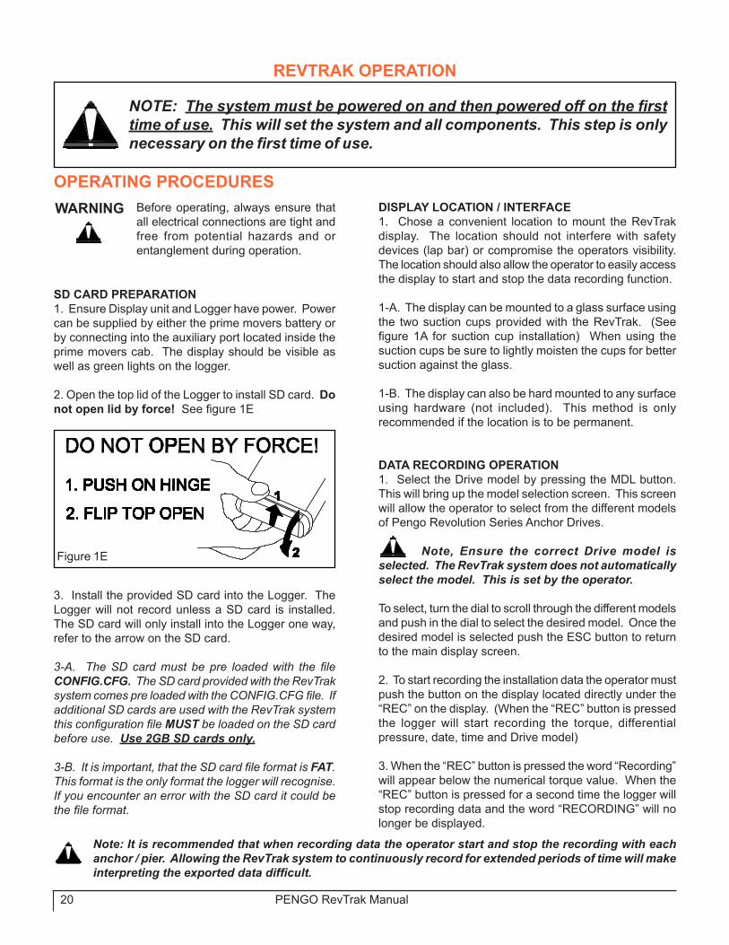
2. Open the top lid of the Logger to install SD card. Do not open lid by force! See figure 1E
3. Install the provided SD card into the Logger. The Logger will not record unless a SD card is installed. The SD card will only install into the Logger one way, refer to the arrow on the SD card.
3-A. The SD card must be pre loaded with the file CONFIG.CFG. The SD card provided with the RevTrak system comes pre loaded with the CONFIG.CFG file. If additional SD cards are used with the RevTrak system this configuration file MUST be loaded on the SD card before use. Use 2GB SD cards only.
3-B. It is important, that the SD card file format is FAT. This format is the only format the logger will recognise. If you encounter an error with the SD card it could be the file format.
wARNING Before operating, always ensure that all electrical connections are tight and free from potential hazards and or entanglement during operation.
Figure �E
DISPLAY LOCATION / INTERFACE�. Chose a convenient location to mount the RevTrak display. The location should not interfere with safety devices (lap bar) or compromise the operators visibility. The location should also allow the operator to easily access the display to start and stop the data recording function.
�-A. The display can be mounted to a glass surface using the two suction cups provided with the RevTrak. (See figure 1A for suction cup installation) When using the suction cups be sure to lightly moisten the cups for better suction against the glass.
�-B. The display can also be hard mounted to any surface using hardware (not included). This method is only recommended if the location is to be permanent.
DATA RECORDING OPERATION�. Select the Drive model by pressing the MDL button. This will bring up the model selection screen. This screen will allow the operator to select from the different models of Pengo Revolution Series Anchor Drives.
Note, Ensure the correct Drive model is selected. The RevTrak system does not automatically select the model. This is set by the operator.
To select, turn the dial to scroll through the different models and push in the dial to select the desired model. Once the desired model is selected push the ESC button to return to the main display screen.
2. To start recording the installation data the operator must push the button on the display located directly under the “REC” on the display. (When the “REC” button is pressed the logger will start recording the torque, differential pressure, date, time and Drive model)
3. When the “REC” button is pressed the word “Recording” will appear below the numerical torque value. When the “REC” button is pressed for a second time the logger will stop recording data and the word “RECORDING” will no longer be displayed.
Note: It is recommended that when recording data the operator start and stop the recording with each anchor / pier. Allowing the RevTrak system to continuously record for extended periods of time will make interpreting the exported data difficult.
NOTE: The system must be powered on and then powered off on the first time of use. This will set the system and all components. This step is only necessary on the first time of use.

PENGO RevTrak Manual 2�
DATA EXPORT (DOwNLOAD)�. Open the top lid of the Logger to remove the SD card. Do not open lid by force! See figure 1E.
2. Remove the SD card from the logger by pressing down on the top of the card to release it from the logger.
3. Remove the end caps from the card reader (�2) to expose the USB connection and the SD card slot. See figure 2E.
4. Place the SD card into the card reader as shown in figure 2E.
5. Connect the card reader to a computer or laptop using the USB port. Once the card reader is connected a red light on the card reader will be visible.
6. The computer or laptop should recognise the card reader automatically. If the card reader window does not appear upon connection, open My Computer and the card reader will be shown as a new drive letter and labeled “Removable Disk”. See figure 3E.
REvTRAK OPERATION
OPERATING PROCEDURES CONT.
Figure 2E
LBS Kg0.00
THIS DRAWING IS THE PROPERTY OF PENGO 500 E. HIGHWAY 10 LAURENS, IA. 50554. NO USE THEREOF SHALL BE MADE OTHER THAN AS A REFERENCE FOR PROPOSALS SUBMITTED BY PENGO CORPORATION AND/OR FOR JOBS BEING EXECUTED IN CONFORMITY WITH SUCH PROPOSALS HAVE BEEN ACCEPTED. UNLESS THE CONSENT OF SAID PENGO CORPORATION HAS BEEN PREVIOUSLY OBTAINED. NO PART OF THIS DRAWING SHALL BE COPPIED OR DUPLICATED OR IT'S CONTENTS DISCLOSED.
DRAWN BYMATERIAL
TITLE:
SIZE REV
SCALE: 1:2
EAM
SHEET 1 OF 1HEAT TREAT
TOLERANCES UNLESS OTHERWISE SPECIFIED.X .1 [2.54 .XX .03 [.76] .XXX .010 [.25] ANGLE 1 DEG.
THIRD ANGLE PROJECTION
A
DATECHECKED BY
610294-300
USB Connection
�2
�0
Insert SD card into card reader. Note orientation of the arrow on the SD card.
End Cap
End Cap
Figure 3E
Open Removable Disk to access RevTrak Data

22 PENGO RevTrak Manual
DATA EXPORT (DOwNLOAD)7. Open the “Removable Disk” drive and two files should be listed:
CONFIG.CFG and Torque.csv
The Torque.csv file contains the installation data. This file can now be downloaded to a computer. See figure 4E. The CONFIG.CFG file does not need to be downloaded. The CONFIG.CFG file must remain on the SD card for future recordings.
Note: Microsoft Excel is required to open and format the raw data recorded by RevTrak.
8. When the Torque.csv file is opened in Microsoft Excel a worksheet will appear with the raw installation data. It is recommended that the file be saved and named by date or by the job number, so the file name Torque is not used. This will prevent data from being copied over or lost.
Model IDThe model selected will be shown with a numeric designation. Pengo Revolution Series models will be represented by a number. See Model Number Key.
REvTRAK OPERATION
OPERATING PROCEDURES CONT.Figure 4E
DRIvE MODEL NUMBER KEYThe Drive model will be represented by a number when the raw data is exported into Excel. Below is the model key:
0 - DS-21 - DS-32 - DT-53 - DT-154 - RS-7 / 7X5 - RS-126 - RT-97 - RT-128 - RT-209 - RT-3010- RT-4011 - Rv-7012 - Rv-10013 - Rv-14014 - Rv-20015 - CUSTOM 116 - CUSTOM 2
CONFIG.CFGThis file is to remain on the SD card permanently. Logger will not recognise SD card without this file.
Torque.csvThis file is the data recorded by the RevTrak. Each time the data is downloaded the file name will be “Torque.csv”
It is highly recommended that the file be saved and named by date or by the job number, so that the file name “Torque” is not used. This will prevent data from being copied over or lost.

PENGO RevTrak Manual 23
REvTRAK DATA ChARTING
DATA ChARTING (RAw DATA)Below is an example of the raw data recorded by the RevTrak system and opened with Microsoft Excel. This data has not been formatted or manipulated. This is the recorded data in its raw format.
Note: All torque values are recorded in FT/LBS
Model_ID DIF PSI Torque Date Time7 900 �726 2�.04.�0 �9:44:34:0047 ��36 2�78 2�.04.�0 �9:44:39:4587 ��90 2282 2�.04.�0 �9:44:44:5237 �254 2405 2�.04.�0 �9:44:49:5787 �306 2504 2�.04.�0 �9:44:54:9007 �389 2663 2�.04.�0 �9:45:00:0757 �459 2798 2�.04.�0 �9:45:05:5�77 �583 3035 2�.04.�0 �9:45:�0:9037 �702 3264 2�.04.�0 �9:45:�6:6887 �939 37�8 2�.04.�0 �9:45:2�:8877 22�2 4242 2�.04.�0 �9:45:27:5�47 2487 4769 2�.04.�0 �9:45:33:0487 �28� 5265 2�.04.�0 �9:45:38:5047 �42� 5840 2�.04.�0 �9:45:44:3707 �673 6876 2�.04.�0 �9:45:50:3437 ��04 2��7 2�.04.�0 �9:48:33:2407 �3�5 252� 2�.04.�0 �9:48:38:7377 �547 2966 2�.04.�0 �9:48:43:8807 �795 3442 2�.04.�0 �9:48:49:2707 �877 3599 2�.04.�0 �9:48:55:�897 2023 3879 2�.04.�0 �9:49:0�:2�77 2�88 4�96 2�.04.�0 �9:49:06:4587 2306 4422 2�.04.�0 �9:49:��:70�7 �204 4948 2�.04.�0 �9:49:�7:3527 �365 56�0 2�.04.�0 �9:49:22:9497 �52� 625� 2�.04.�0 �9:49:28:7847 �689 6942 2�.04.�0 �9:49:34:0787 �8�� 7443 2�.04.�0 �9:49:39:5307 2023 83�4 2�.04.�0 �9:49:44:6707 ���9 2�46 2�.04.�0 �9:52:4�:27�7 �303 2498 2�.04.�0 �9:52:46:3067 �458 2796 2�.04.�0 �9:52:5�:6867 �6�0 3087 2�.04.�0 �9:52:57:�577 �788 3429 2�.04.�0 �9:53:03:�397 �923 3688 2�.04.�0 �9:53:08:3887 2�06 4039 2�.04.�0 �9:53:�3:8487 2257 4328 2�.04.�0 �9:53:�8:8877 240� 4604 2�.04.�0 �9:53:24:6087 ��97 49�9 2�.04.�0 �9:53:30:0077 �387 5700 2�.04.�0 �9:53:35:0877 �486 6�07 2�.04.�0 �9:53:40:5477 �62� 6662 2�.04.�0 �9:53:45:8867 �772 7283 2�.04.�0 �9:53:5�:2937 �902 78�7 2�.04.�0 �9:53:56:3�87 2�08 8664 2�.04.�0 �9:54:02:060
Models recorded by numeric code. See Model Key.
Differential Pressure(PSI)
Torque Value(Ft/Lbs)
Date(DD.MM.YY) Time
(HH:MM:SS:MS)
Look for time gaps. Time Gaps indicate breaks between anchor installations.
Decrease in pressure while torque continues to increase ind ica tes tha t the Dr ive shifted from low torque to high torque. (Two Speed Models only)
Time Gap
Model Code7 = RT-�2
Note: It is recommended that when recording data the operator start and stop the recording with each anchor / pier. Allowing the RevTrak system to continuously record for extended periods of time will make interpreting the exported data difficult.

24 PENGO RevTrak Manual
REvTRAK DATA ChARTING
DATA ChARTING (CUSTOMIZED DATA FORMAT)Below is an example of the raw data customized in Microsoft Excel. This is only an example of a custom format to allow for easier analysis.
Note: All torque values are recorded in FT/LBS
Model_ID DIF PSI Torque Date TimeRT-�2 900 �726 2�.04.�0 �9:44:34:004RT-�2 ��36 2�78 2�.04.�0 �9:44:39:458RT-�2 ��90 2282 2�.04.�0 �9:44:44:523RT-�2 �254 2405 2�.04.�0 �9:44:49:578RT-�2 �306 2504 2�.04.�0 �9:44:54:900RT-�2 �389 2663 2�.04.�0 �9:45:00:075RT-�2 �459 2798 2�.04.�0 �9:45:05:5�7RT-�2 �583 3035 2�.04.�0 �9:45:�0:903RT-�2 �702 3264 2�.04.�0 �9:45:�6:688RT-�2 �939 37�8 2�.04.�0 �9:45:2�:887RT-�2 22�2 4242 2�.04.�0 �9:45:27:5�4RT-�2 2487 4769 2�.04.�0 �9:45:33:048RT-�2 �28� 5265 2�.04.�0 �9:45:38:504RT-�2 �42� 5840 2�.04.�0 �9:45:44:370RT-�2 �673 6876 2�.04.�0 �9:45:50:343
Model_ID DIF PSI Torque Date TimeRT-�2 ��04 2��7 2�.04.�0 �9:48:33:240RT-�2 �3�5 252� 2�.04.�0 �9:48:38:737RT-�2 �547 2966 2�.04.�0 �9:48:43:880RT-�2 �795 3442 2�.04.�0 �9:48:49:270RT-�2 �877 3599 2�.04.�0 �9:48:55:�89RT-�2 2023 3879 2�.04.�0 �9:49:0�:2�7RT-�2 2�88 4�96 2�.04.�0 �9:49:06:458RT-�2 2306 4422 2�.04.�0 �9:49:��:70�RT-�2 �204 4948 2�.04.�0 �9:49:�7:352RT-�2 �365 56�0 2�.04.�0 �9:49:22:949RT-�2 �52� 625� 2�.04.�0 �9:49:28:784RT-�2 �689 6942 2�.04.�0 �9:49:34:078RT-�2 �8�� 7443 2�.04.�0 �9:49:39:530RT-�2 2023 83�4 2�.04.�0 �9:49:44:670
Model_ID DIF PSI Torque Date TimeRT-�2 ���9 2�46 2�.04.�0 �9:52:4�:27�RT-�2 �303 2498 2�.04.�0 �9:52:46:306RT-�2 �458 2796 2�.04.�0 �9:52:5�:686RT-�2 �6�0 3087 2�.04.�0 �9:52:57:�57RT-�2 �788 3429 2�.04.�0 �9:53:03:�39RT-�2 �923 3688 2�.04.�0 �9:53:08:388RT-�2 2�06 4039 2�.04.�0 �9:53:�3:848RT-�2 2257 4328 2�.04.�0 �9:53:�8:887RT-�2 240� 4604 2�.04.�0 �9:53:24:608RT-�2 ��97 49�9 2�.04.�0 �9:53:30:007RT-�2 �387 5700 2�.04.�0 �9:53:35:087RT-�2 �486 6�07 2�.04.�0 �9:53:40:547RT-�2 �62� 6662 2�.04.�0 �9:53:45:886RT-�2 �772 7283 2�.04.�0 �9:53:5�:293RT-�2 �902 78�7 2�.04.�0 �9:53:56:3�8RT-�2 2�08 8664 2�.04.�0 �9:54:02:060
Pier
1Pi
er 2
Pier
3A chart end cap was added to easily distinguish each Pier installation.
The numeric model code has been replaced by the actual model number.

PENGO RevTrak Manual 25
REvTRAK DATA ChARTING
0�00020003000400050006000700080009000
�0000
�9:44
:34:00
4
�9:44
:49:57
8
�9:45
:05:5�
7
�9:45
:2�:88
7
�9:45
:38:50
4
�9:48
:33:24
0
�9:48
:49:27
0
�9:49
:06:45
8
�9:49
:22:94
9
�9:49
:39:53
0
�9:52
:46:30
6
�9:53
:03:�3
9
�9:53
:�8:88
7
�9:53
:35:08
7
�9:53
:5�:29
3
Time
Torq
ue /
PSI
DIF PSITorque
DATA ChARTING (CUSTOMIZED BAR ChART FORMAT)Below is an example of the raw data customized in Microsoft Excel to display in bar chart format. In bar chart format the individual pier installations is clear by the rise and fall of the torque / pressure. In this example the DIF PSI, Torque and Time data columns were selected to create the bar chart.
Note: All torque values are recorded in FT/LBS
A bar chart format clearly illustrates torque progression from start to stop.

26 PENGO RevTrak Manual
DISPLAY LAYOUTS
Main DisplayThis is the main operating screen. On this screen the operator can view the overall torque, Port A and B pressures, the time and date, the SD card status, recording status, battery level, Drive model selected, and any active errors.
The MENU button will bring you to the Menu Screen. The REC button starts and stops the data recording. The MDL button brings the operator to the Model Select Screen.
Faults:A fault description will appear in the top left corner of the display if a fault is detected. These include:
Communication FaultPort A Transducer FaultPort B Transducer FaultSequence (High/Low Speed) Transducer FaultLow Battery Fault (Wireless Option Only)
Battery Level (wireless Option Only):The battery symbol has 0-4 bars internally to indicate battery level.When the battery power is full, four bars will appear in the battery symbol.When the battery power is almost depleted, no bars will appear accompanied by the words “BATT LOW”
SD Card:When an SD card is inserted, the SD card symbol will be shown.When an SD card is not inserted, the SD card symbol with an X through it will be shown.To the right of the SD card symbol is a proportional gauge that indicates how full the SD card is. The black bar will rise as the SD card fills up.If the SD card is full, the “FULL” text will appear just below the SD card symbol.If the SD card is locked, the “LOCKED” text will appear just below the SD card symbol.
•••••
•••
•••
••

PENGO RevTrak Manual 27
DISPLAY LAYOUTS
Model Selection DisplayThis screen will allow the operator to select from the different models of Pengo Revolution Series Anchor Drives.
To select, turn the dial to scroll through the different models and push in the dial to select the desired model. Once the desired model is selected push the ESC button to return to the main display screen.

28 PENGO RevTrak Manual
DISPLAY LAYOUTS
CUSTOM 1 AND 2 DisplayThis screen is the same setup for both Custom Screen 1 and 2. First the operator can scroll through which field they want to change with the dial and then select it by pressing in the dial. Second the operator will select a value for each decimal place and press the dial to enter that number. The number entry selection starts from the left side of the screen and moves to the right. The following parameters include:
Motor Displacement in cubic inches (0.00 decimal places)*Efficiency of the system (0.00% decimal places)Gearbox ratio (0.00 decimal places)
* Efficiency refers to the Drives total mechanical efficiency regarding the hydraulic motor and the gearbox. To determine how efficient a Drive is the hydraulic motor and gearbox efficiencies need to be added together to determine the total amount of efficiencies to be subtracted from 100%.
Example: 15% - Motor (Motor is 85% efficient) +3% - Gearbox (Gearbox is 97% efficient) 18% - Total (Efficiency to be subtracted)
100% - Starting efficiency - 18% - Total (Efficiency to be subtracted) 82% - Total Drive Efficiency. 82% is the overall Drive efficiency and will be entered in the System Efficiency box.
•••
NOTE: The Two Speed button (located on the bottom right next to the ESC button) toggles between On and Off depending on if the Drive is a two speed model. If the option is set to “Off” then the Stage 2 numbers will not be used in the calculations. If it is set to “On” then the Stage 2 numbers will be used in the calculations.The two speed option is only to be used with Pengo RT series Anchor Drives. The custom two speed option will not recognise other manufactures Drives.
See Efficiency example below.
In order to enter values in the Stage 2 boxes this button must be set to “ON”.
Enter displacement in cubic inches.
Note: The gearbox and motor efficiencies can normally be obtained from the Drive manufacturer.

PENGO RevTrak Manual 29
DISPLAY LAYOUTS
Main Menu DisplayOn this screen the operator can choose to navigate to a variety of screens by rotating the dial. To select a screen, press the dial on the display. These screens include:
Password MenuSystem MenuCustom � SetupCustom 2 SetupExit
•••••
System Menu DisplayOn this screen the operator can choose to navigate to a variety of screens by rotating the dial. To select a screen, press the dial on the display. These screens include:
CAN MenuLighting Adjustment ScreenTime/Date MenuExit
••••
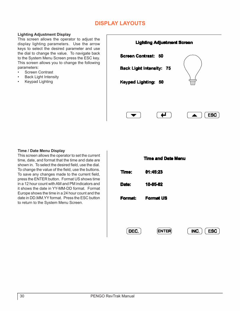
30 PENGO RevTrak Manual
Lighting Adjustment DisplayThis screen allows the operator to adjust the display lighting parameters. Use the arrow keys to select the desired parameter and use the dial to change the value. To navigate back to the System Menu Screen press the ESC key. This screen allows you to change the following parameters:
Screen ContrastBack Light IntensityKeypad Lighting
•••
Time / Date Menu DisplayThis screen allows the operator to set the current time, date, and format that the time and date are shown in. To select the desired field, use the dial. To change the value of the field, use the buttons. To save any changes made to the current field, press the ENTER button. Format US shows time in a �2 hour count with AM and PM indicators and it shows the date in YY-MM-DD format. Format Europe shows the time in a 24 hour count and the date in DD.MM.YY format. Press the ESC button to return to the System Menu Screen.
DISPLAY LAYOUTS

PENGO RevTrak Manual 3�
LIMITED wARRANTYPENGO, warrants its products against faulty design, material, and workmanship for the periods listed below. The warranty starts on the delivery date to the retail owner and is non-transferable.
wARRANTY PERIOD (Dating from the delivery to the original user)RevTrak System: �2 months.
wARRANTY SERvICEAll new PENGO products are warranted to be free from defects in material and workmanship, which may cause failure under normal usage and service when used for the purpose intended.The PENGO warranty covers faulty workmanship and defective parts manufactured by PENGO. The warranty does not extend to transportation cost of parts nor does it cover consequential loss.
PENGO Equipment must be operated in accordance with the recommended procedures and within the ranges as specified both on the Unit and contained in the Operating Manual.Any claims under this warranty must be made within fourteen (�4) days after the buyer learns of the facts upon which claim is based. All claims not made in writing and not received by PENGO within the time specified above may be deemed waived. PENGO will not be responsible for or accept any charges for work carried out by any repairs, or for any charges for any spare parts fitted to any PENGO products without written approval from PENGO. PENGO’s liability for any and all losses and damages to buyer resulting from any cause whatsoever, including PENGO negligence irrespective of whether such defects are discoverable or latent, shall in no event exceed the purchase price of the particular parts, with respect to which losses or damages are claimed, or, at the discretion of PENGO the repair or replacement of defective or damaged parts.
vOID wARRANTYThis warranty is void if field repairs or modifications have been made to the RevTrak controls without written approval. The complete unit must be available for inspection in it’s original but alleged failed condition. This warranty does not apply to normal wear or to damage resulting from accident, abnormal use, abuse or neglect.
PRODUCT IMPROvEMENTSProduct improvement and modifications is an on going process at PENGO. PENGO reserves the right to make changes or additions to any product or to the warranty without incurring any obligations to make such changes available for previously sold products.
PENGO makes no other warranty. All other warranties, whether expressed or implied, such as warranties of mechantablity or fitness for a particular purpose, are hereby excluded and disclaimed to the extent that they exceed the warranties expressly granted in this limited warranty. In no event shall PENGO be liable for consequential or incidental damages.
wARRANTY POLICY
PENGO reserves the right to determine whether products claimed to be defective shall be inspected by our personnel in the field or returned to the factory. If judged by PENGO to be defective in material or workmanship, the product will be replaced or a credit issued at the option of Pengo.
Upon notification of defect, PENGO’s Inside Sales Department will issue a Return Materials Authorization (RMA) number. All returns for replacement or credit MUST be accompanied by a RMA number. Products returned without an RMA number will be rejected and returned to the sender freight collect. All returns must be shipped “prepaid”. Products shipped “collect” will be refused. Proof of purchase such as invoice number must accompany returns.
All RMA’s must be returned within 30 days of the request.
RETURNED GOODS POLICY

32 PENGO RevTrak Manual
Utility headquartersIowa
500 East Highway �0Laurens, IA 50554 PH: 800-599-02��FX: 7�2-845-2497
Minnesota�3369 60th St. S.W.Cokato, MN 5532�PH: 888-286-0982FX: 320-286-5583
www.pengoattachments.com
Printed in the USA