Embed Size (px)
Citation preview
www.productivity.com320MN 763.476.4196 • IA 319.734.3403 • NE 402.330.2323
Taps - Technical Information Ta
ps
- Te
ch
nic
al I
nfo
High Performance HSSE Ring Colored Taps Speeds
Workpiece Material Ring Color Speed (SFM) Speed (SFM)
Steels Low, Medium and High Carbon Yellow 40-90 —
Stainless Steels 400 Series Red 20-40 —
PH Series Red 8-20 —
Steels Alloy Green 30-60 —
High Temp Alloys Hastelloy, Inconel, Monel Blue 8-20 10-25
Titanium Blue 20-50 23-55
Stainless Steels 300 Series Blue 10-30 12-35
Aluminum Wrought Black 90-150 —
Die Casting Black 65-75 —
Cast Iron Gray White 20-80 —
Ductile White 30-50 —
• RedLine Torque Cut High Performance Taps give you greater performance when tapping Steel Alloys, Stainless Steels, Titanium and a variety of other Steels with a maximum Rc of 32.
• Made from High Vanadium Powdered Metal, Torque Cut Taps provide the right combination of strength and abrasion resistance, which gives you increased speeds, while achieving longer tool life and a lower cost per thread.
• Use XHP premium material geometry and coating taps for extreme performance or difficult applications
• High Performance Taps found on pages 267-300.
Torque Cut High Performance HSSE Ring Colored Taps Technical Information
www.productivity.com 321MN 763.476.4196 • IA 319.734.3403 • NE 402.330.2323
TapsTechnical Information -
Tap
s -
Tec
hn
ica
l In
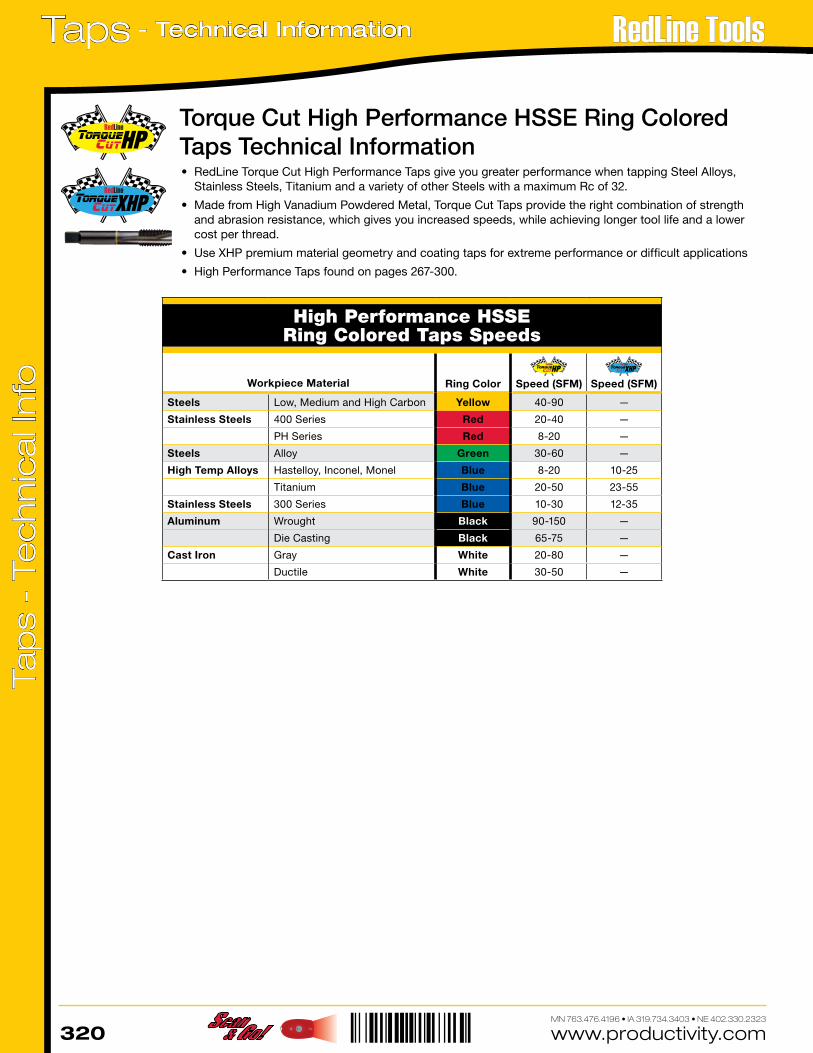
foMachine Screw Sizes NC & NF Fractional Sizes NC & NF
Nom. Size Tap
RecommendedTap Drill Probable
Hole SizeActual % Thread
Nom. Size Tap
RecommendedTap Drill Probable
Hole SizeActual % ThreadDrill Decimal Drill Decimal
0 - 80 3/64 .0469 .0484 71 1/4 - 28 3 .2130 .2168 721 - 64 53 .0595 .0610 59 5/16 - 18 F .2570 .2608 721 - 72 53 .0595 .0610 67 5/16 - 24 I .2720 .2761 672 - 56 50 .0700 .0717 62 3/8 - 16 5/16 .3125 .3169 722 - 64 50 .0700 .0717 70 3/8 - 24 Q .3320 .3364 713 - 48 47 .0785 .0804 69 7/16 - 14 U .3680 .3726 703 - 56 46 .0810 .0829 69 7/16 - 20 W .3860 .3906 724 - 40 43 .0890 .0910 65 1/2 - 13 27/64 .4219 .4266 734 - 48 42 .0935 .0955 61 1/2 - 20 29/64 .4531 .4578 655 - 40 39 .0995 .1018 71 9/16 - 12 31/64 .4844 .4892 685 - 44 38 .1015 .1038 72 9/16 - 18 33/64 .5156 .5204 586 - 32 36 .1065 .1091 71 5/8 - 11 17/32 .5313 .53620 756 - 40 33 .1130 .1156 69 5/8 - 18 37/64 .5781 .5831 588 - 32 29 .1360 .1389 62 3/4 - 10 21/32 .6562 .6613 688 - 36 29 .1360 .1389 70 3/4 - 16 11/16 .6875 .69250 7110 - 24 25 .1495 .1527 69 7/8 - 9 49/64 .7656 .7708 7210 - 32 21 .1590 .1622 68 7/8 - 14 13/16 .8125 .8177 6212 - 24 17 .1730 .1765 73 1 - 8 7/8 .8750 .8809 7312 - 28 15 .1800 .1835 70 1 - 12 59/64 .9219 .9279 671/4 - 20 7 .2010 .2048 70 1 - 14 15/16 .9375 .9435 61
Taper Pipe Taps Roll Form Taps - App. 65% Thread
Nom. Size
Tap Drill
Tap Drill Tap DrillNPT NPTF
1/16 - 27 D C 0 - 80 54 12-28 81/8 - 27 Q Q 1 - 64 1.65MM 1/4-20 11/4 - 18 7/16 7/16 1 - 72 1.7MM 1/4-28 A3/8 - 18 9/16 9/16 2 - 56 5/64 5/16-18 7.3MM1/2 - 14 45/64 45/64 2 - 64 2MM 5/16-24 M3/4 - 14 29/32 29/32 3 - 48 43 3/8-16 8.8MM
1 - 11-1/2 1-9/64 1-9/64 3 - 56 2.3MM 3/8-24 T1-1/4 - 11-1/2 1-31/64 1-31/64 4 - 40 39 7/16-14 Y1-1/2 - 11-1/2 1-47/64 1-23/32 4 - 48 2.6MM 7/16-20 10.5MM
2 - 1-1/2 2-13/64 2-3/16 5 - 40 33 1/2-13 11.8MM2-1/2 - 8 2-5/8 2-39/64 5 - 44 2.9MM 1/2-20 12.0MM
3 - 8 3-1/4 3-15/64 6 - 32 1/8 9/16-12 17/32— — — 6 - 40 3.2MM 9/16-18 13.5MM— — — 8 - 32 25 5/8-11 14.75MM— — — 8 - 36 24 5/8-18 15.25MM— — — 10 - 24 11/64 3/4-10 45/64— — — 10 - 32 16 3/4-16 23/32— — — 12 - 24 5MM — —
Tap Drill Chart
Metric Tap Drill Size (Recommended Drill Sizes Suitable for 6H Tolerance)
Tap SizeCutting Tap
Drill SizeRoll Form Tap
Drill Size Tap SizeCutting Tap
Drill SizeRoll Form Tap
Drill Size Tap SizeCutting Tap
Drill Size
M1.6 x 0.35 1.25MM — M10 x 1.5 8.5MM 9.20MM M24 x 3 53/64M1.8 X 0.35 1.45 MM — M10 x 1.25 8.75MM U M24 x 2 22MM
M2 x 0.4 1.60MM — M12 x 1.75 13/32 7/16 M27 x 3 24MMM2.2 x 0.45 1.75MM — M12 x 1.25 10.75MM .447* M27 x 2 63/64M2.5 x 0.45 2.05MM — M14 x 2 12MM 13MM M30 x 3.5 1-3/64*
M3 x 0.5 2.5MM 7/64 M14 x 1.5 12.5MM 13.20MM M30 x 2 1-7/64*M3.5 x .06 2.9MM 3.2MM M16 x 2 14MM 15MM M33 x 3.5 1-11/64*M4 x 0.7 3.3MM #27 M16 x 1.5 14.5MM 15.25MM M33 x 2 31MM*
M4.5 x 0.75 3.75MM 4.10MM M18 x 1.5 15.5MM 16.25MM M36 x 4 32MM*M5 x 0.8 #19 4.60MM M18 x 1.5 16.5MM 17.25MM M36 x 3 33MM*M6 x 1 5MM 5.50MM M20 x 2.5 17.5MM 47/64 M39 x 4 35MM*M7 x 1 6MM 6.50MM M20 x 1.5 18.5MM .757* M39 x 3 36MM*
M8 x 1.25 H L M22 x 2.5 19.5MM — — —M8 x 1 J 7.50MM M22 x 1.5 20.5MM — * Reaming Recommended
www.productivity.com322MN 763.476.4196 • IA 319.734.3403 • NE 402.330.2323
Taps - Technical Information Ta
ps
- Te
ch
nic
al I
nfo
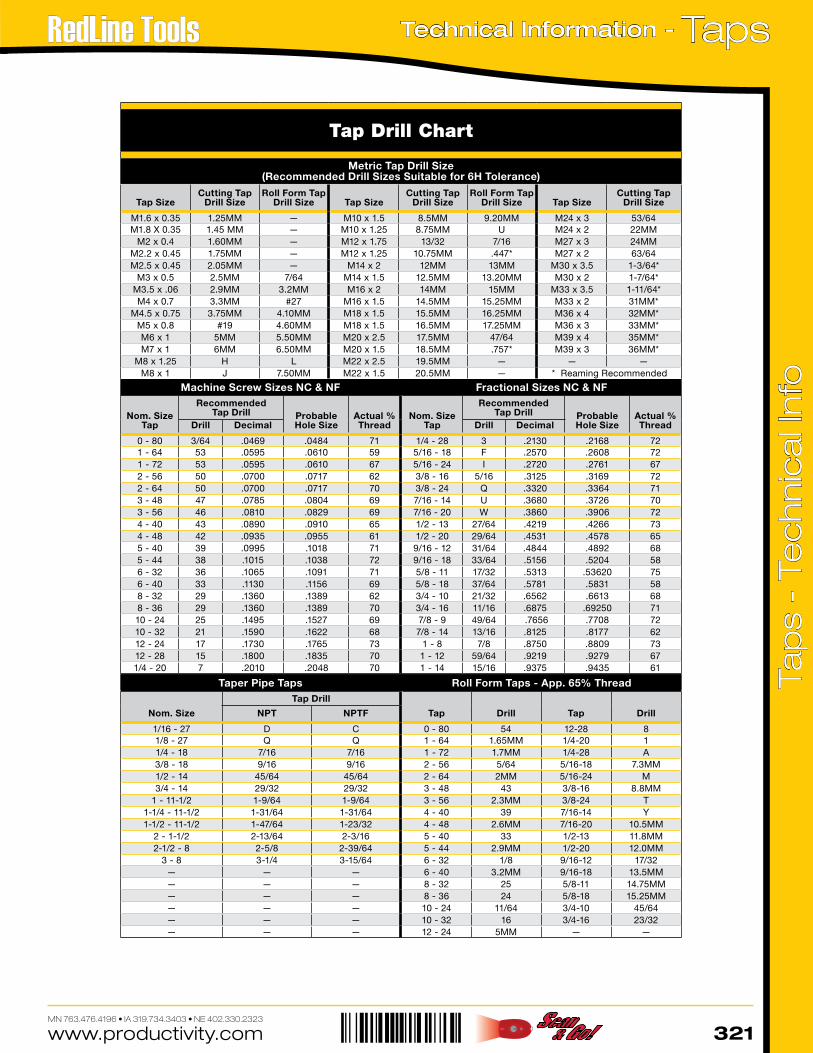
General Purpose & OtherTaps Speeds
Workpiece Material Speed (SFM)
Non-Ferrous Materials
Aluminum 70-90
Brass/Bronze 60-100
Copper/Copper Alloys 60-80
Plastics 50-70
Cast Iron
Malleable 30-60
Ductile 15-30
Steels
Low Carbon Steels 20-40
Medium Alloy Steels 200, 250, 300 20-30
High Strength Steels 15-25
Stainless Steels
PH Series 10-20
Austenitic 200,302, 303, 304, 304(L), 316(L) 10-20
Martensitic 403,410,416,420,440 10-20
High Temp Alloys
Nickel Based Inconel 601, 625, 718, Waspalloy, Hastelloy 10-25
Cobalt Based Stellite, Haynes 25 10-25
Iron Based Incolloy 800-802, Haynes 556 10-25
Titanium 5-15
NOTES: Speeds listed are estimated and will vary by application.
www.productivity.com 323MN 763.476.4196 • IA 319.734.3403 • NE 402.330.2323
TapsTechnical Information -
Tap
s -
Tec
hn
ica
l In
fo
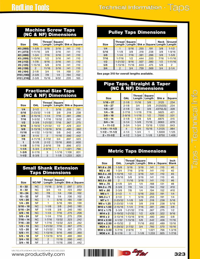
(SS) = Small Shank (LS) = Large Shank
See page 310 for overall lengths available.
Machine Screw Taps(NC & NF) Dimensions
Size OALThread Length
Square Length Shk ø Square
#0 (.060) 1-5/8 5/16 3/16 .141 .110#1 (.073) 1-11/16 3/8 3/16 .141 .110#2 (.066) 1-3/4 7/16 3/16 .141 .110#3 (.099) 1-13/16 1/2 3/16 .141 .110#4 (.112) 1-7/8 9/16 3/16 .141 .110#5 (.125) 1-15/16 5/8 3/16 .141 .110#6 (.138) 2 11/16 3/16 .141 .110#8 (.164) 2-1/8 3/4 1/4 .168 .131#10 (.190) 2-3/8 7/8 1/4 .194 .152#12 (.216) 2-3/8 15/16 9/32 .220 .165
Fractional Size Taps(NC & NF) Dimensions
Size OALThread Length
Square Length Shk ø Square
1/4 2-1/2 1 5/16 .255 .1915/16 2-23/32 1-1/8 3/8 .318 .2383/8 2-15/16 1-1/4 7/16 .381 .2867/16 3-5/32 1-7/16 13/32 .323 .2421/2 3-3/8 1-21/32 7/16 .367 .275
9/16 3-19/32 1-21/32 1/2 .429 .3225/8 3-13/16 1-13/16 9/16 .480 .360
11/16 4-1/32 1-13/16 5/8 .542 .4063/4 4-1/4 2 11/16 .590 .4427/8 4-11/16 2-7/32 3/4 .697 .5231 5-1/8 2-1/2 13/16 .800 .600
1-1/8 5-7/16 2-9/16 7/8 .896 .6721-1/4 5-3/4 2-9/16 1 1.021 .7661-3/8 6-1/16 3 1-1/16 1.108 .8311-1/2 6-3/8 3 1-1/8 1.233 .925
Pipe Taps, Straight & Taper(NC & NF) Dimensions
Size OALThread Length
Square Length Shk ø Square
1/16 – 27 2-1/8 11/16 3/8 .3125 .2341/8 – 27 2-1/8 3/4 3/8 .3125(SS) .2341/8 – 27 2-1/8 3/4 3/8 .4375(LS) .3281/4 – 18 2-7/16 1-1/16 7/16 .5625 .4213/8 – 18 2-9/16 1-1/16 1/2 .7000 .5311/2 – 14 3-1/8 1-3/8 5/8 .6875 .5153/4 – 14 3-1/4 1-3/8 11/16 .9063 .679
1 – 11-1/2 3-3/4 1-3/4 13/16 1.1250 .8431-1/4 – 11-1/2 4 1-3/4 15/16 1.3125 .9841-1/2 – 11-1/2 4-1/4 1-3/4 1 1.5000 1.125
2 – 11-1/2 4-1/2 1-3/4 1-1/8 1.8750 1.406
Pulley Taps Dimensions
SizeThread Length
Square Length Shk ø Square
NeckLength
Ground Length
1/4 1 5/16 .255 .191 3/8 1-1/25/16 1-1/8 3/8 .318 .238 3/8 1-9/163/8 1-1/4 7/16 .381 .286 3/8 1-5/87/16 1-7/16 1/2 .444 .333 7/16 1-11/161/2 1-21/32 9/16 .507 .380 1/2 1-11/165/8 1-13/16 11/16 .633 .475 5/8 23/4 2 3/4 .759 .569 3/4 2-1/4
Metric Taps Dimensions
Size OALThread Length
Square Length Shk ø Square
Inch Blank
M1.6 x .35 1-5/8 5/16 3/16 .141 .110 #0M2 x .40 1-3/4 7/16 3/16 .141 .110 #2
M2.5 x .45 1-13/16 1/2 3/16 .141 .110 #3M3 x .50 1-15/16 5/8 3/16 .141 .110 #5
M3.5 x .60 2 11/16 3/16 .141 .110 #6M4 x .70 2-1/8 3/4 1/4 .168 .131 #8
M4.5 x .75 2-3/8 7/8 1/4 .194 .152 #10M5 x .80 2-3/8 7/8 1/4 .194 .152 #10M6 x 1 2-1/2 1 5/16 .255 .191 1/4
M6.3 x 1 2-1/2 1 5/16 .255 .191 1/4M7 x 1 2-23/32 1-1/8 3/8 .318 .238 5/16
M8 x 1.25 2-23/32 1-1/8 3/8 .318 .238 5/16M10 x 1.50 2-15/16 1-1/4 7/16 .381 .286 3/8M12 x 1.75 3-3/8 1-21/32 7/16 .367 .275 1/2
M14 x 2 3-19/32 1-21/32 1/2 .429 .322 9/16M16 x 2 3-13/16 1-13/16 9/16 .480 .360 5/8
M18 x 2.50 4-1/32 1-13/16 5/8 .542 .406 11/16M20 x 2.50 4-15/32 2 11/16 .652 .489 13/16
M24 x 3 4-29/32 2-7/32 3/4 .760 .570 15/16M30 x 3.50 5-7/16 2-9/16 1 1.021 .766 1-3/16
M36 x 4 6-1/16 3 1-1/8 1.233 .925 1-7/16
Small Shank Extension Taps Dimensions
Size NC/NFThread Length
Square Length Shk ø Square
6 – 32 NC 11/16 3/16 .097 .073 8 – 32 NC 3/4 1/4 .123 .092 10 – 24 NC 7/8 1/4 .136 .102 10 – 32 NF 7/8 1/4 .136 .102 1/4 – 20 NC 1 5/16 .185 .139 1/4 – 28 NF 1 5/16 .185 .139 5/16 – 18 NC 1-1/8 3/8 .240 .180 5/16 – 24 NF 1-1/8 3/8 .240 .180 3/8 – 16 NC 1-1/4 7/16 .275 .206 3/8 – 24 NF 1-1/4 7/16 .275 .206 7/16 – 14 NC 1-7/16 13/32 .323 .242 7/16 – 20 NF 1-7/16 13/32 .323 .242 1/2 – 13 NC 1-21/32 7/16 .367 .275 1/2 – 20 NF 1-21/32 7/16 .367 .275 5/8 – 11 NC 1-13/16 9/16 .480 .360 5/8 – 18 NF 1-13/16 9/16 .480 .360 3/4 – 10 NC 2 11/16 .590 .442 3/4 – 16 NF 2 11/16 .590 .442
www.productivity.com324MN 763.476.4196 • IA 319.734.3403 • NE 402.330.2323
Taps - Technical Information Ta
ps
- Te
ch
nic
al I
nfo
StyleS of tapS
The type of hole to be tapped has much to do with the chamfer style of that tap that's best suited. Some holes go all the way through. Some, while not through-holes, are relatively deep; some are quite shallow (a little deeper than diameter). Each of these three kinds of holes - through, deep-bottoming blind, and shallow bottoming has a tap best suited to threading requirements.
taper tapS
This style with a 7-10 thread chamfer, has the longest chamfer of the three to distribute action over the maximum number of teeth. The taper also acts as a guide in starting the cutting action in the hole.
plug tapS
This style, with a 4-6 thread chamfer, is most widely used in through holes and where there is sufficient room at the bottom in blind holes.
Bottoming tapS
This style, with a 1-2 thread chamfer, is made with just enough chamfer for starting in the hole. As the name implies, it is designed to thread blind holes to the bottom.
tap SizeS
Tap sizes have been standardized to conform with those of standard screws, bolts and studs. Machine Screw tap size range from No. 0 through No. 14; No. 0 being .0600" outside diameter; No. 1 being .0730"; No. 2 being .0860, etc all in .0130" increments.
threadS per inch
A measurement shown for various tooth forms. The Unified series adopted by Great Britain during the war and the corresponding American National Standard. NC and UNC mean coarse thread. NF and UNF mean fine thread. NS means special thread.
pitch diameter
This is the basic dimension of a screw, threaded hole or a tap — the diameter of an imaginary cylinder, the surface of which passes through the thread where width of thread and space between threads are identical. This cylinder would be a cone for tapered taps. It is upon Pitch Diameter that tolerance limits are based to establish Class of Thread.
claSS of thread
There are three established Classes of Thread, designated in the Unified series by adding "A" for screws and "B" for nuts (or other internal threads) to show definite limits and tolerances.
claSS 1B thread
The hole is classified as 1B when a 1A screw can be run in readily for quick and easy assembly. The fit is 1B Thread and is rarely used in today's metalworking.
claSS 2B thread
This is a 2A screw in a 2B hole. This 2B Thread has wide applica-tion, accommodates plating, finishes and coating to a limited extent and therefore has fair tolerance allowances.
claSS 3B thread
This is a 3A screw in a 3B nut or threaded hole for applications where tolerance limits are close.
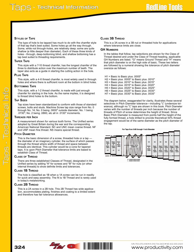
gh numBerS
In the tables that follow, tap selections are shown for the Class of Thread desired and under the Class of Thread heading, applicable GH Numbers are listed. "G" means Ground Thread and "H" means that pitch diameter is on the high side of basic. These two letters are followed by a numeral showing the tolerance of pitch diameter oversize as follows:
H1 = Basic to Basic plus .0005"H2 = Basic plus .0005" to Basic plus .0010"H3 = Basic plus .0010" to Basic plus .0015"H4 = Basic plus .0015" to Basic plus .0020"H5 = Basic plus .0020" to Basic plus .0025"H6 = Basic plus .0025" to Basic plus .0030"H7 = Basic plus .0030" to Basic plus .0035"
The diagram below, exaggerated for clarity, illustrates these several selectives in Pitch Diameter tolerance—including "L" (undersize tol-erance), although no "L" taps are shown in this book. Pitch Diameter varies with the number of threads per inch because the number of threads of Pitch of screw determines the height of thread. Since Basic Pitch Diameter is measured from points half the height of the fully formed thread, a hole drilled to provide theoretical 50% thread engagement would be of the same diameter as the pitch diameter of the tap.
www.productivity.com 325MN 763.476.4196 • IA 319.734.3403 • NE 402.330.2323
TapsTechnical Information -
Tap
s -
Tec
hn
ica
l In
fo
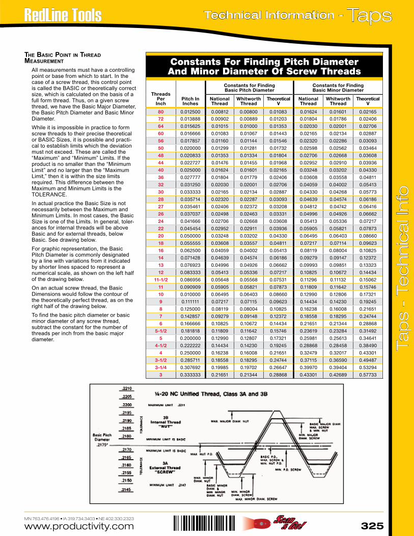
the BaSic point in thread meaSurement
All measurements must have a controlling point or base from which to start. In the case of a screw thread, this control point is called the BASIC or theoretically correct size, which is calculated on the basis of a full form thread. Thus, on a given screw thread, we have the Basic Major Diameter, the Basic Pitch Diameter and Basic Minor Diameter.While it is impossible in practice to form screw threads to their precise theoretical or BASIC Sizes, it is possible and practi-cal to establish limits which the deviation must not exceed. These are called the “Maximum” and “Minimum” Limits. If the product is no smaller than the “Minimum Limit” and no larger than the “Maximum Limit,” then it is within the size limits required. This difference between the Maximum and Minimum Limits is the TOLERANCE.In actual practice the Basic Size is not necessarily between the Maximum and Minimum Limits. In most cases, the Basic Size is one of the Limits. In general, toler-ances for internal threads will be above Basic and for external threads, below Basic. See drawing below.For graphic representation, the Basic Pitch Diameter is commonly designated by a line with variations from it indicated by shorter lines spaced to represent a numerical scale, as shown on the left half of the drawing below.On an actual screw thread, the Basic Dimensions would follow the contour of the theoretically perfect thread, as on the right half of the drawing below.To find the basic pitch diameter or basic minor diameter of any screw thread, subtract the constant for the number of threads per inch from the basic major diameter.
Constants For Finding Pitch Diameter And Minor Diameter Of Screw Threads
Threads PerInch
Pitch InInches
Constants for FindingBasic Pitch Diameter
Constants for FindingBasic Minor Diameter
NationalThread
WhitworthThread
TheoreticalV
NationalThread
WhitworthThread
TheoreticalV
80 0.012500 0.00812 0.00800 0.01083 0.01624 0.01601 0.02165
72 0.013888 0.00902 0.00889 0.01203 0.01804 0.01786 0.02406
64 0.015625 0.01015 0.01000 0.01353 0.02030 0.02001 0.02706
60 0.016666 0.01083 0.01067 0.01443 0.02165 0.02134 0.02887
56 0.017857 0.01160 0.01144 0.01546 0.02320 0.02286 0.03093
50 0.020000 0.01299 0.01281 0.01732 0.02598 0.02562 0.03464
48 0.020833 0.01353 0.01334 0.01804 0.02706 0.02668 0.03608
44 0.022727 0.01476 0.01455 0.01968 0.02952 0.02910 0.03936
40 0.025000 0.01624 0.01601 0.02165 0.03248 0.03202 0.04330
36 0.027777 0.01804 0.01779 0.02406 0.03608 0.03558 0.04811
32 0.031250 0.02030 0.02001 0.02706 0.04059 0.04002 0.05413
30 0.033333 0.02165 0.02134 0.02887 0.04330 0.04268 0.05773
28 0.035714 0.02320 0.02287 0.03093 0.04639 0.04574 0.06186
27 0.035461 0.02406 0.02372 0.03208 0.04812 0.04742 0.06416
26 0.037037 0.02498 0.02463 0.03331 0.04996 0.04926 0.06662
24 0.041666 0.02706 0.02668 0.03608 0.05413 0.05336 0.07217
22 0.045454 0.02952 0.02911 0.03936 0.05905 0.05821 0.07873
20 0.050000 0.03248 0.03202 0.04330 0.06495 0.06403 0.08660
18 0.055555 0.03608 0.03557 0.04811 0.07217 0.07114 0.09623
16 0.062500 0.04059 0.04002 0.05413 0.08119 0.08004 0.10825
14 0.071428 0.04639 0.04574 0.06186 0.09279 0.09147 0.12372
13 0.076923 0.04996 0.04926 0.06662 0.09993 0.09851 0.13323
12 0.083333 0.05413 0.05336 0.07217 0.10825 0.10672 0.14434
11-1/2 0.086956 0.05648 0.05568 0.07531 0.11296 0.11132 0.15062
11 0.090909 0.05905 0.05821 0.07873 0.11809 0.11642 0.15746
10 0.010000 0.06495 0.06403 0.08660 0.12990 0.12806 0.17321
9 0.111111 0.07217 0.07115 0.09623 0.14434 0.14230 0.19245
8 0.125000 0.08119 0.08004 0.10825 0.16238 0.16008 0.21651
7 0.142857 0.09279 0.09148 0.12372 0.18558 0.18295 0.24744
6 0.166666 0.10825 0.10672 0.14434 0.21651 0.21344 0.28868
5-1/2 0.181818 0.11809 0.11642 0.15746 0.23619 0.23284 0.31492
5 0.200000 0.12990 0.12807 0.17321 0.25981 0.25613 0.34641
4-1/2 0.222222 0.14434 0.14230 0.19245 0.28868 0.28458 0.38490
4 0.250000 0.16238 0.16008 0.21651 0.32479 0.32017 0.43301
3-1/2 0.285711 0.18558 0.18295 0.24744 0.37115 0.36590 0.49487
3-1/4 0.307692 0.19985 0.19702 0.26647 0.39970 0.39404 0.53294
3 0.333333 0.21651 0.21344 0.28868 0.43301 0.42689 0.57733
www.productivity.com326MN 763.476.4196 • IA 319.734.3403 • NE 402.330.2323
Taps - Technical Information Ta
ps
- Te
ch
nic
al I
nfo
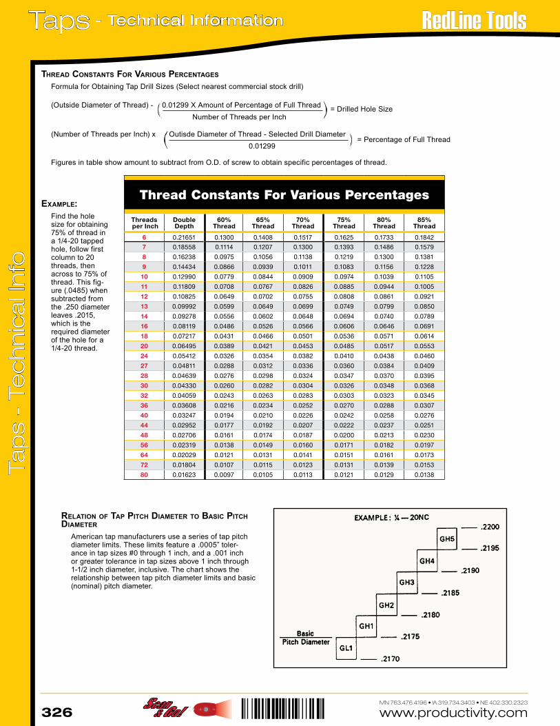
Thread Constants For Various Percentages
Threads per Inch
Double Depth
60%Thread
65%Thread
70%Thread
75%Thread
80%Thread
85%Thread
6 0.21651 0.1300 0.1408 0.1517 0.1625 0.1733 0.1842
7 0.18558 0.1114 0.1207 0.1300 0.1393 0.1486 0.1579
8 0.16238 0.0975 0.1056 0.1138 0.1219 0.1300 0.1381
9 0.14434 0.0866 0.0939 0.1011 0.1083 0.1156 0.1228
10 0.12990 0.0779 0.0844 0.0909 0.0974 0.1039 0.1105
11 0.11809 0.0708 0.0767 0.0826 0.0885 0.0944 0.1005
12 0.10825 0.0649 0.0702 0.0755 0.0808 0.0861 0.0921
13 0.09992 0.0599 0.0649 0.0699 0.0749 0.0799 0.0850
14 0.09278 0.0556 0.0602 0.0648 0.0694 0.0740 0.0789
16 0.08119 0.0486 0.0526 0.0566 0.0606 0.0646 0.0691
18 0.07217 0.0431 0.0466 0.0501 0.0536 0.0571 0.0614
20 0.06495 0.0389 0.0421 0.0453 0.0485 0.0517 0.0553
24 0.05412 0.0326 0.0354 0.0382 0.0410 0.0438 0.0460
27 0.04811 0.0288 0.0312 0.0336 0.0360 0.0384 0.0409
28 0.04639 0.0276 0.0298 0.0324 0.0347 0.0370 0.0395
30 0.04330 0.0260 0.0282 0.0304 0.0326 0.0348 0.0368
32 0.04059 0.0243 0.0263 0.0283 0.0303 0.0323 0.0345
36 0.03608 0.0216 0.0234 0.0252 0.0270 0.0288 0.0307
40 0.03247 0.0194 0.0210 0.0226 0.0242 0.0258 0.0276
44 0.02952 0.0177 0.0192 0.0207 0.0222 0.0237 0.0251
48 0.02706 0.0161 0.0174 0.0187 0.0200 0.0213 0.0230
56 0.02319 0.0138 0.0149 0.0160 0.0171 0.0182 0.0197
64 0.02029 0.0121 0.0131 0.0141 0.0151 0.0161 0.0173
72 0.01804 0.0107 0.0115 0.0123 0.0131 0.0139 0.0153
80 0.01623 0.0097 0.0105 0.0113 0.0121 0.0129 0.0138
relation of tap pitch diameter to BaSic pitch diameter
American tap manufacturers use a series of tap pitch diameter limits. These limits feature a .0005” toler-ance in tap sizes #0 through 1 inch, and a .001 inch or greater tolerance in tap sizes above 1 inch through 1-1/2 inch diameter, inclusive. The chart shows the relationship between tap pitch diameter limits and basic (nominal) pitch diameter.
(Outside Diameter of Thread) - 0.01299 X Amount of Percentage of Full Thread Number of Threads per Inch
= Drilled Hole Size
thread conStantS for VariouS percentageS
Formula for Obtaining Tap Drill Sizes (Select nearest commercial stock drill)
= Percentage of Full Thread(Number of Threads per Inch) x Outisde Diameter of Thread - Selected Drill Diameter
0.01299
Figures in table show amount to subtract from O.D. of screw to obtain specific percentages of thread.
example:Find the hole size for obtaining 75% of thread in a 1/4-20 tapped hole, follow first column to 20 threads, then across to 75% of thread. This fig-ure (.0485) when subtracted from the .250 diameter leaves .2015, which is the required diameter of the hole for a 1/4-20 thread.
www.productivity.com 327MN 763.476.4196 • IA 319.734.3403 • NE 402.330.2323
TapsTechnical Information -
Tap
s -
Tec
hn
ica
l In
fo
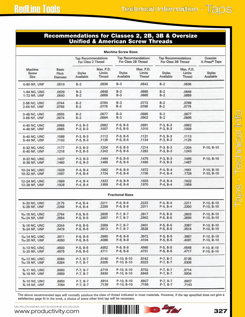
Recommendations for Classes 2, 2B, 3B & Oversize Unified & American Screw Threads
Machine Screw Sizes
Fractional Sizes
www.productivity.com328MN 763.476.4196 • IA 319.734.3403 • NE 402.330.2323
Taps - Technical Information Ta
ps
- Te
ch
nic
al I
nfo
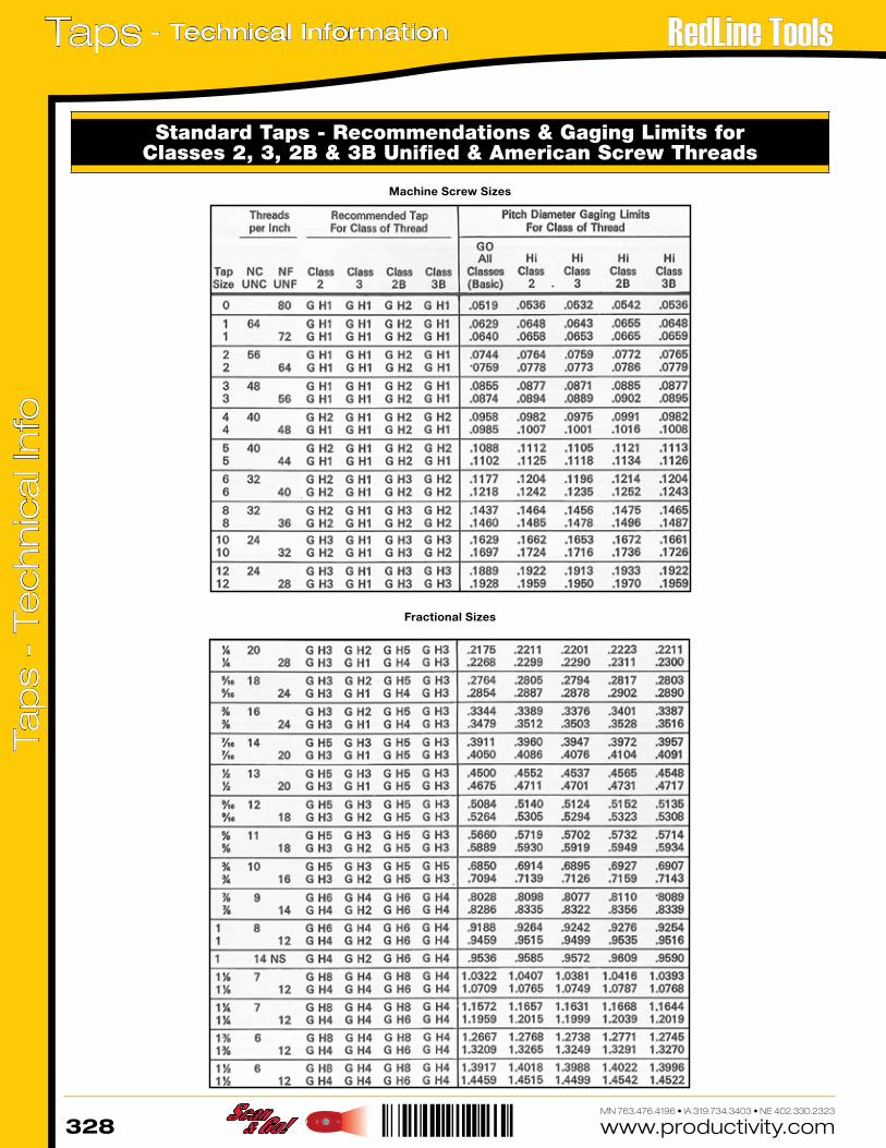
Standard Taps - Recommendations & Gaging Limits for Classes 2, 3, 2B & 3B Unified & American Screw Threads
Machine Screw Sizes
Fractional Sizes
www.productivity.com 329MN 763.476.4196 • IA 319.734.3403 • NE 402.330.2323
TapsTechnical Information -
Tap
s -
Tec
hn
ica
l In
fo
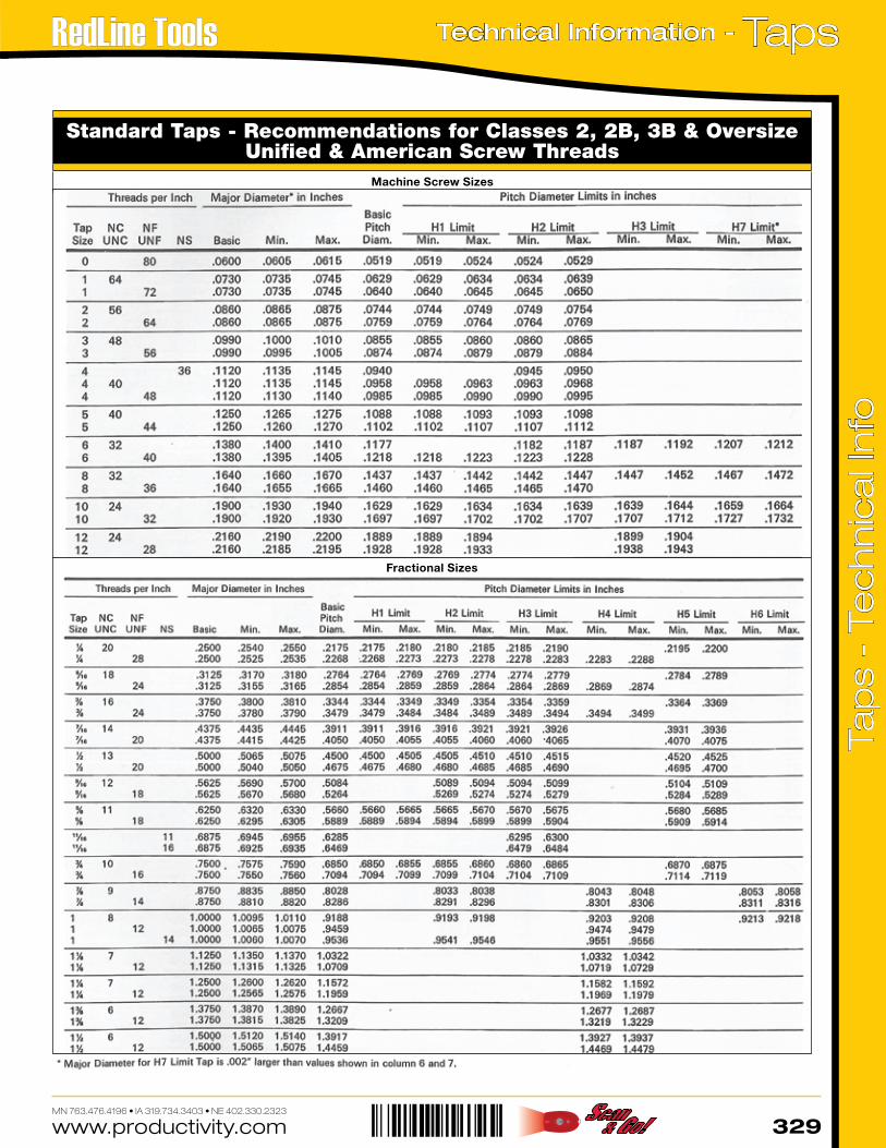
Fractional Sizes
Standard Taps - Recommendations for Classes 2, 2B, 3B & OversizeUnified & American Screw Threads
Machine Screw Sizes
www.productivity.com330MN 763.476.4196 • IA 319.734.3403 • NE 402.330.2323
Taps - Technical Information Ta
ps
- Te
ch
nic
al I
nfo
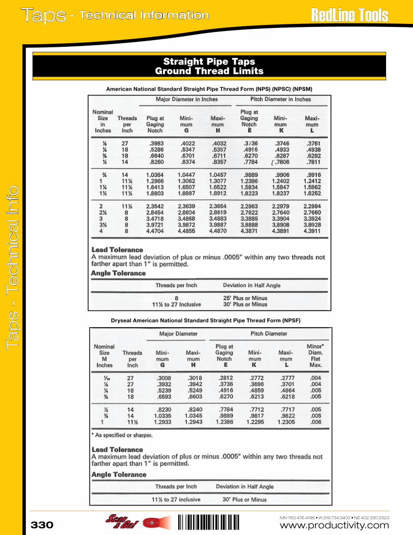
Straight Pipe TapsGround Thread Limits
American National Standard Straight Pipe Thread Form (NPS) (NPSC) (NPSM)
Dryseal American National Standard Straight Pipe Thread Form (NPSF)
www.productivity.com 331MN 763.476.4196 • IA 319.734.3403 • NE 402.330.2323
TapsTechnical Information -
Tap
s -
Tec
hn
ica
l In
fo
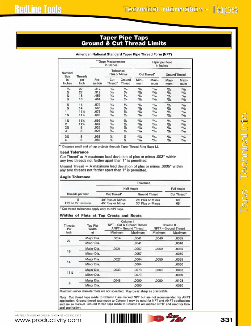
Taper Pipe TapsGround & Cut Thread Limits
American National Standard Taper Pipe Thread Form (NPT)
www.productivity.com332MN 763.476.4196 • IA 319.734.3403 • NE 402.330.2323
Taps - Technical Information Ta
ps
- Te
ch
nic
al I
nfo
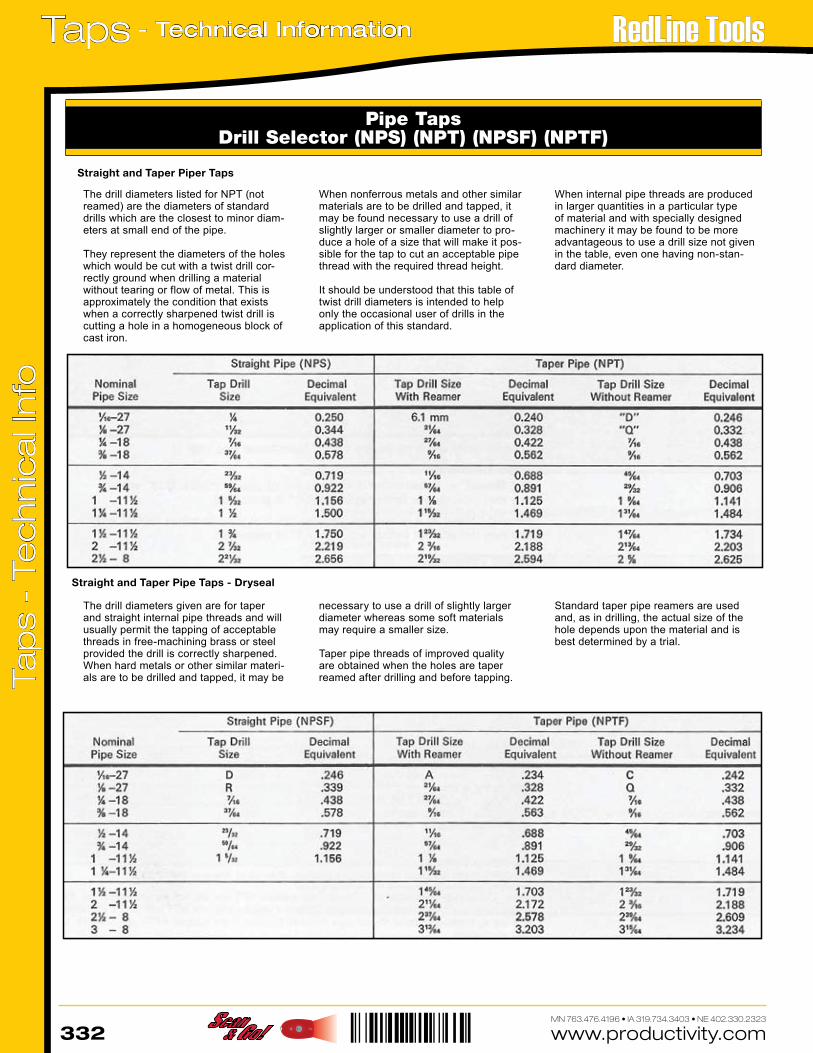
Pipe TapsDrill Selector (NPS) (NPT) (NPSF) (NPTF)
Straight and Taper Piper Taps
Straight and Taper Pipe Taps - Dryseal
The drill diameters listed for NPT (not reamed) are the diameters of standard drills which are the closest to minor diam-eters at small end of the pipe. They represent the diameters of the holes which would be cut with a twist drill cor-rectly ground when drilling a material without tearing or flow of metal. This is approximately the condition that exists when a correctly sharpened twist drill is cutting a hole in a homogeneous block of cast iron.
When nonferrous metals and other similar materials are to be drilled and tapped, it may be found necessary to use a drill of slightly larger or smaller diameter to pro-duce a hole of a size that will make it pos-sible for the tap to cut an acceptable pipe thread with the required thread height. It should be understood that this table of twist drill diameters is intended to help only the occasional user of drills in the application of this standard.
When internal pipe threads are produced in larger quantities in a particular type of material and with specially designed machinery it may be found to be more advantageous to use a drill size not given in the table, even one having non-stan-dard diameter.
The drill diameters given are for taper and straight internal pipe threads and will usually permit the tapping of acceptable threads in free-machining brass or steel provided the drill is correctly sharpened. When hard metals or other similar materi-als are to be drilled and tapped, it may be
necessary to use a drill of slightly larger diameter whereas some soft materials may require a smaller size. Taper pipe threads of improved quality are obtained when the holes are taper reamed after drilling and before tapping.
Standard taper pipe reamers are used and, as in drilling, the actual size of the hole depends upon the material and is best determined by a trial.