Embed Size (px)
Citation preview
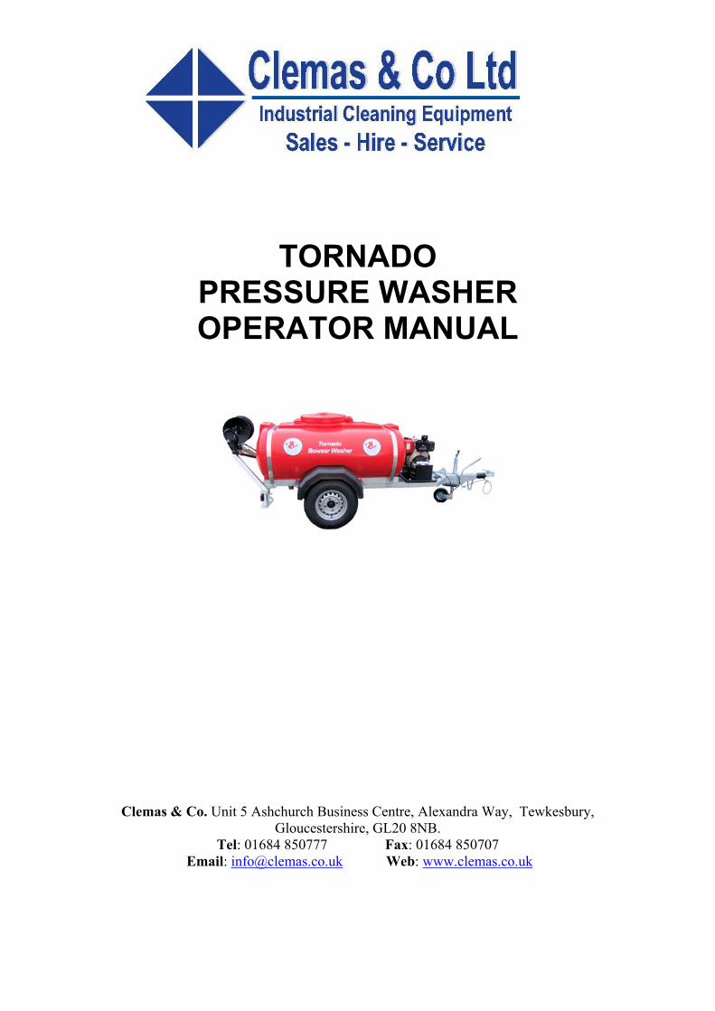
TORNADO
PRESSURE WASHER OPERATOR MANUAL
Clemas & Co. Unit 5 Ashchurch Business Centre, Alexandra Way, Tewkesbury, Gloucestershire, GL20 8NB.
Tel: 01684 850777 Fax: 01684 850707 Email: [email protected] Web: www.clemas.co.uk
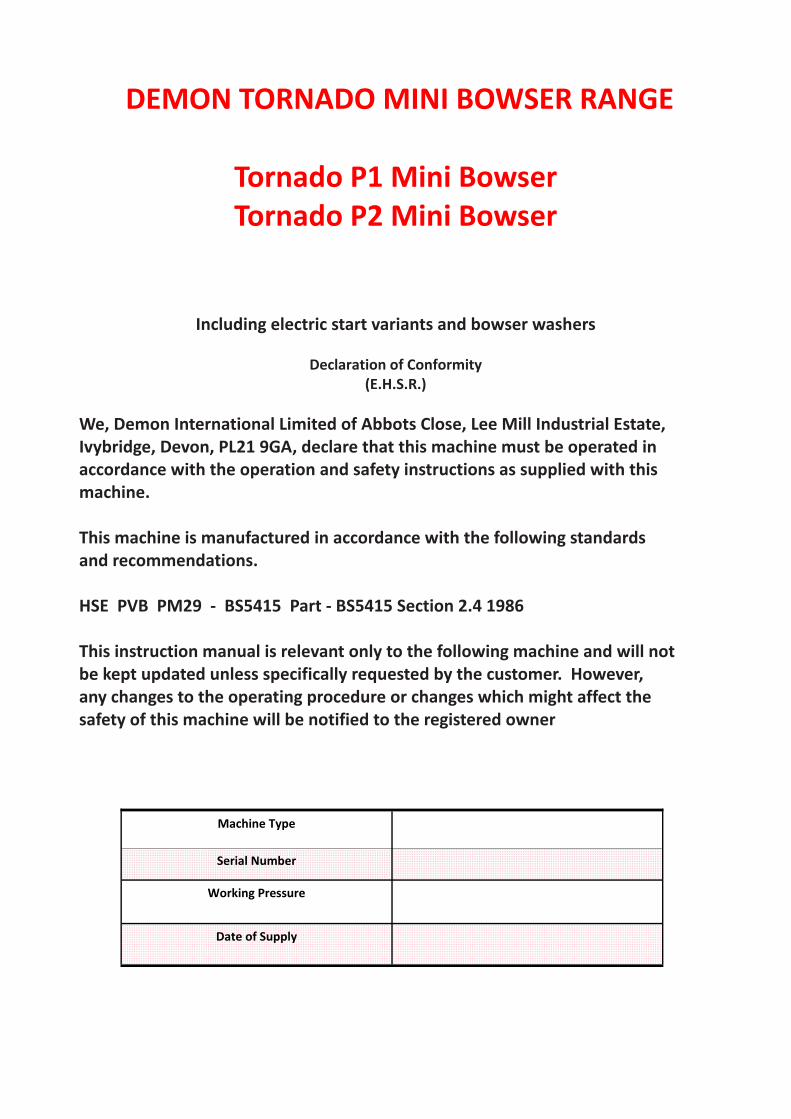
DEMON TORNADO MINI BOWSER RANGE
Tornado P1 Mini Bowser Tornado P2 Mini Bowser
Including electric start variants and bowser washers
Declaration of Conformity (E.H.S.R.)
We, Demon International Limited of Abbots Close, Lee Mill Industrial Estate, Ivybridge, Devon, PL21 9GA, declare that this machine must be operated in accordance with the operation and safety instructions as supplied with this machine. This machine is manufactured in accordance with the following standards and recommendations. HSE PVB PM29 ‐ BS5415 Part ‐ BS5415 Section 2.4 1986 This instruction manual is relevant only to the following machine and will not be kept updated unless specifically requested by the customer. However, any changes to the operating procedure or changes which might affect the safety of this machine will be notified to the registered owner
Machine Type
Serial Number
Working Pressure
Date of Supply
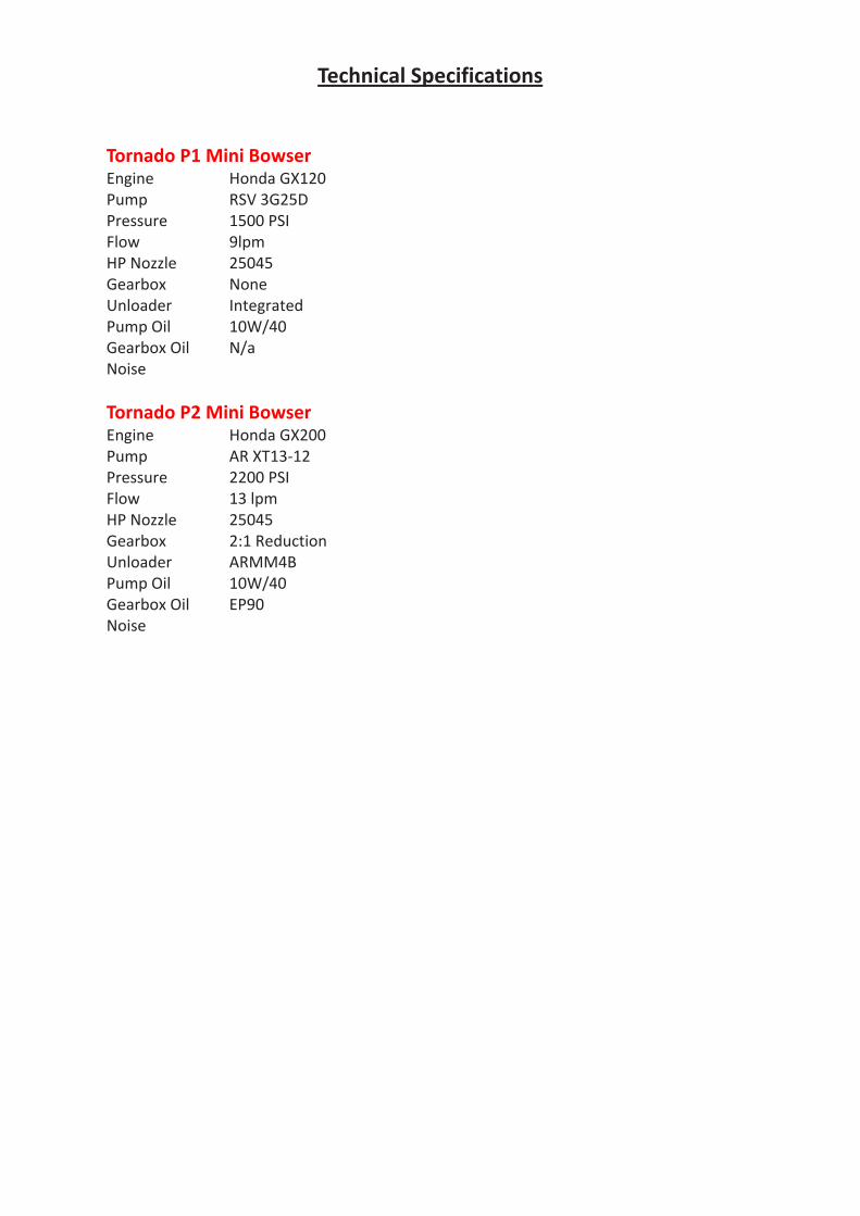
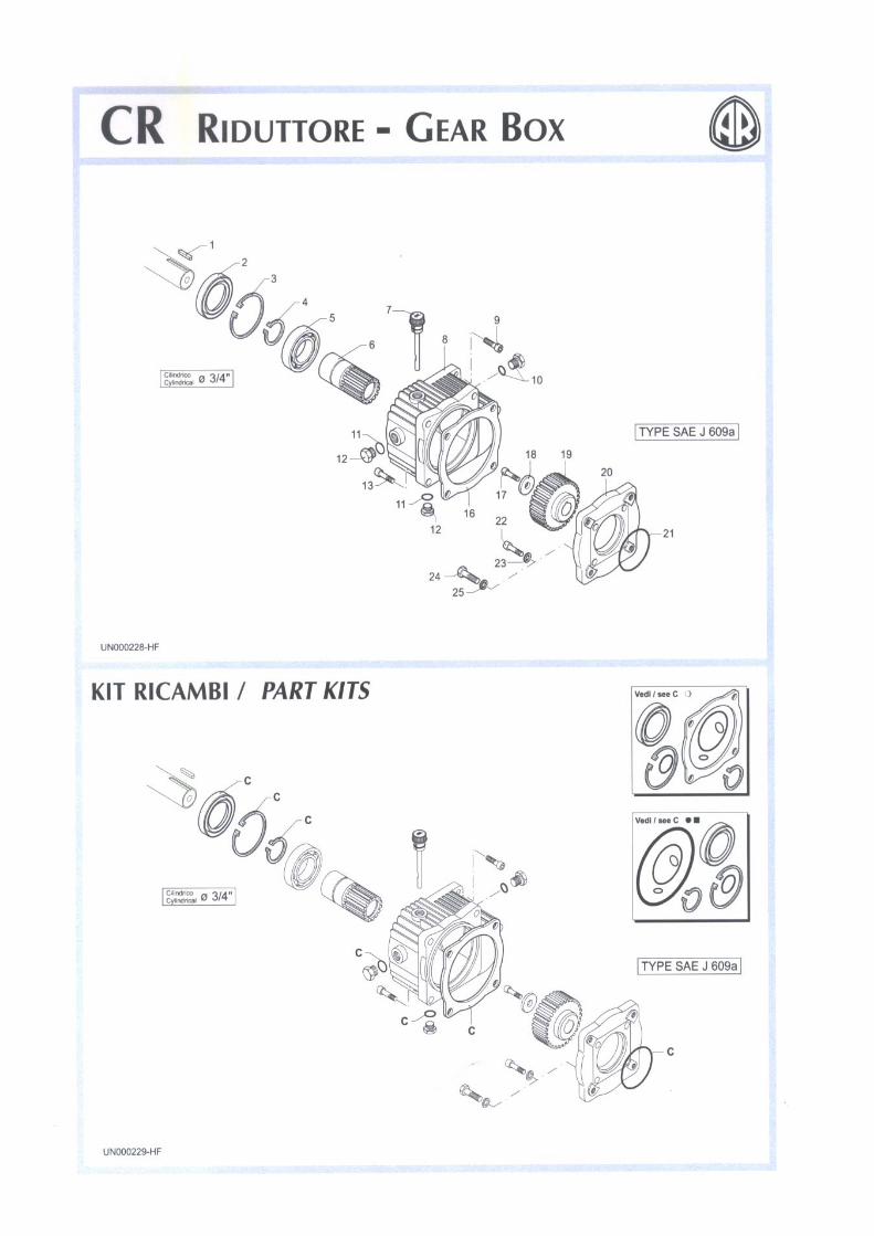
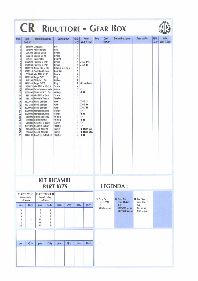
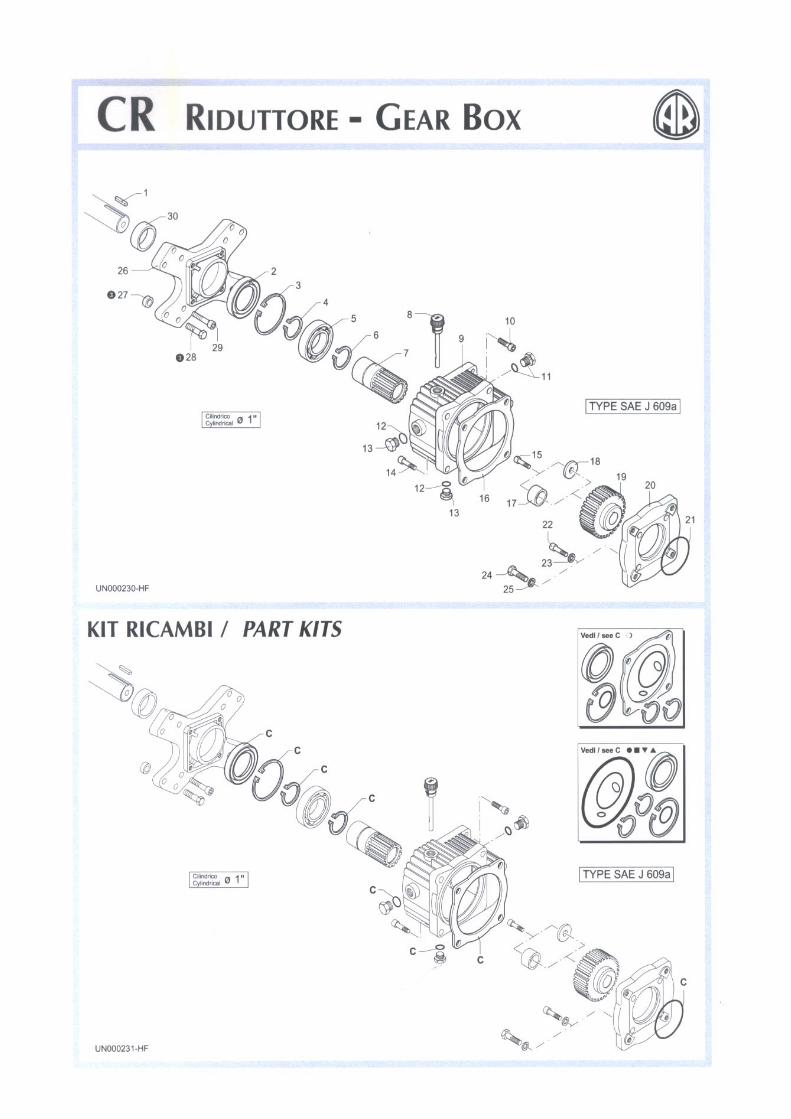
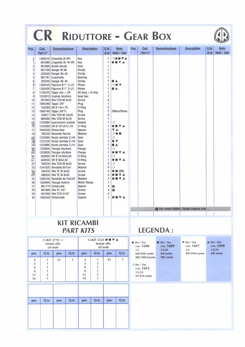
Tornado P1 Mini Bowser Engine Honda GX120 Pump RSV 3G25D Pressure 1500 PSI Flow 9lpm HP Nozzle 25045 Gearbox None Unloader Integrated Pump Oil 10W/40 Gearbox Oil N/a Noise Tornado P2 Mini Bowser Engine Honda GX200 Pump AR XT13‐12 Pressure 2200 PSI Flow 13 lpm HP Nozzle 25045 Gearbox 2:1 Reduction Unloader ARMM4B Pump Oil 10W/40 Gearbox Oil EP90 Noise
Technical Specifications
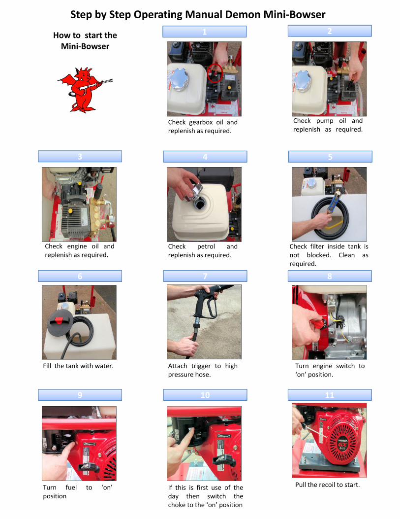
Step by Step Operating Manual Demon Mini‐Bowser1 2How to start the
Mini‐Bowser
Check gearbox oil andreplenish as required
Check pump oil andreplenish as required.replenish as required. ep e s as equ ed
3 4 5
Check engine oil andreplenish as required.
Check petrol andreplenish as required.
Check filter inside tank isnot blocked. Clean asrequired.
6 7 8
Fill the tank with water. Attach trigger to highpressure hose.
Turn engine switch to‘on’ position.
9 10 11
Turn fuel to ‘on’position
If this is first use of theday then switch thechoke to the ‘on’ position
Pull the recoil to start.
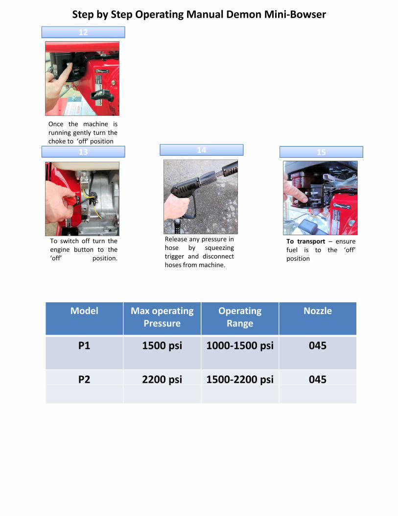
Step by Step Operating Manual Demon Mini‐Bowser
12
Once the machine isi tl t th
13 15
running gently turn thechoke to ‘off’ position
14
To switch off turn theengine button to the‘off’ position
To transport – ensurefuel is to the ‘off’position
Release any pressure inhose by squeezingtrigger and disconnectoff position. positiontrigger and disconnecthoses from machine.
Model Max operating P
Operating R
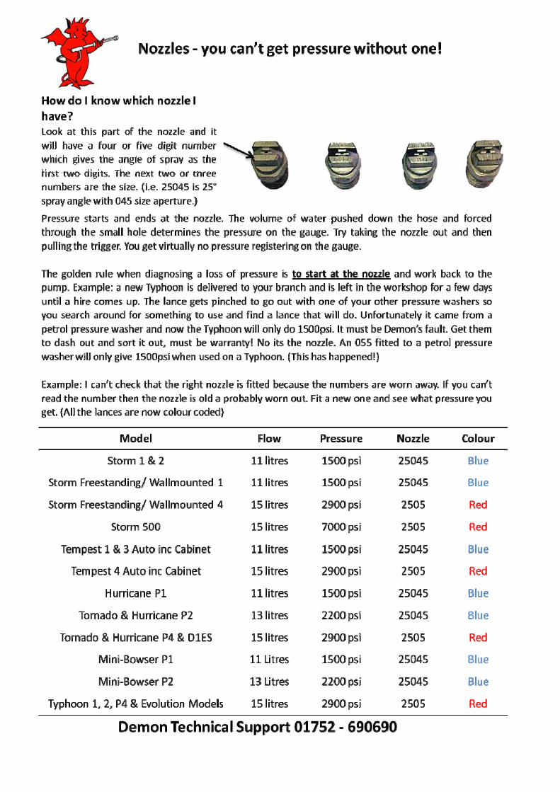
NozzlePressure Range
P1 1500 psi 1000‐1500 psi 045
P2 2200 psi 1500‐2200 psi 045p p
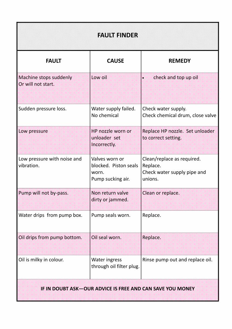
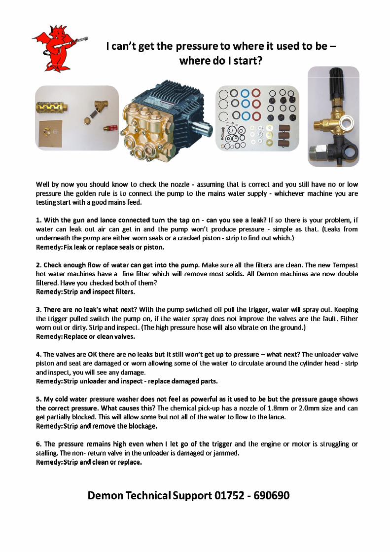
FAULT FINDER
FAULT
CAUSE
REMEDY
Machine stops suddenly Or will not start.
Low oil
• check and top up oil
Sudden pressure loss. Water supply failed. No chemical
Check water supply. Check chemical drum, close valve
Low pressure HP nozzle worn or unloader set Incorrectly.
Replace HP nozzle. Set unloader to correct setting.
Low pressure with noise and vibration.
Valves worn or blocked. Piston seals worn. Pump sucking air.
Clean/replace as required. Replace. Check water supply pipe and unions.
Pump will not by‐pass. Non return valve dirty or jammed.
Clean or replace.
Water drips from pump box. Pump seals worn. Replace.
Oil drips from pump bottom. Oil seal worn. Replace.
Oil is milky in colour. Water ingress through oil filter plug.
Rinse pump out and replace oil.
IF IN DOUBT ASK—OUR ADVICE IS FREE AND CAN SAVE YOU MONEY
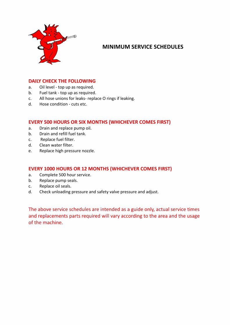
DAILY CHECK THE FOLLOWING a. Oil level ‐ top up as required. b. Fuel tank ‐ top up as required. c. All hose unions for leaks‐ replace O rings if leaking. d. Hose condition ‐ cuts etc.
EVERY 500 HOURS OR SIX MONTHS (WHICHEVER COMES FIRST) a. Drain and replace pump oil. b. Drain and refill fuel tank. c. Replace fuel filter. d. Clean water filter. e. Replace high pressure nozzle.
EVERY 1000 HOURS OR 12 MONTHS (WHICHEVER COMES FIRST) a. Complete 500 hour service. b. Replace pump seals. c. Replace oil seals. d. Check unloading pressure and safety valve pressure and adjust. The above service schedules are intended as a guide only, actual service times and replacements parts required will vary according to the area and the usage of the machine.
MINIMUM SERVICE SCHEDULES
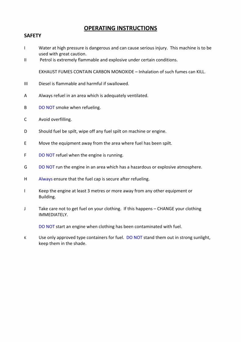
OPERATING INSTRUCTIONS SAFETY I Water at high pressure is dangerous and can cause serious injury. This machine is to be
used with great caution. II Petrol is extremely flammable and explosive under certain conditions.
EXHAUST FUMES CONTAIN CARBON MONOXIDE – Inhalation of such fumes can KILL.
III Diesel is flammable and harmful if swallowed. A Always refuel in an area which is adequately ventilated.
B DO NOT smoke when refueling.
C Avoid overfilling.
D Should fuel be spilt, wipe off any fuel spilt on machine or engine.
E Move the equipment away from the area where fuel has been spilt.
F DO NOT refuel when the engine is running.
G DO NOT run the engine in an area which has a hazardous or explosive atmosphere.
H Always ensure that the fuel cap is secure after refueling.
I Keep the engine at least 3 metres or more away from any other equipment or Building.
J Take care not to get fuel on your clothing. If this happens – CHANGE your clothing IMMEDIATELY.
DO NOT start an engine when clothing has been contaminated with fuel.
K Use only approved type containers for fuel. DO NOT stand them out in strong sunlight,
keep them in the shade.
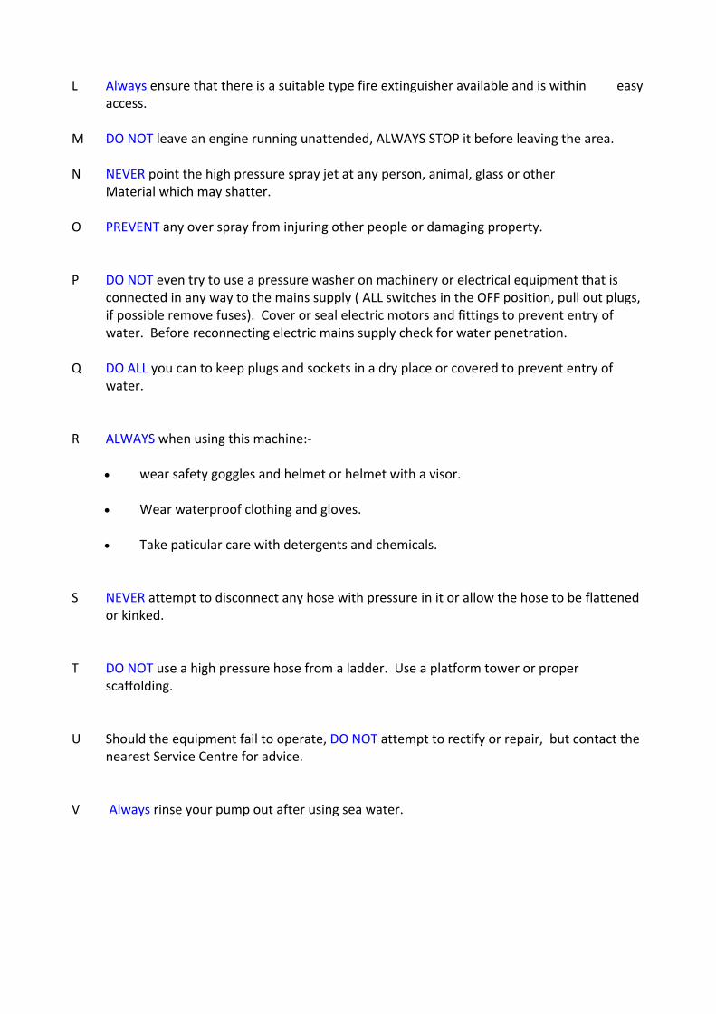
L Always ensure that there is a suitable type fire extinguisher available and is within easy access. M DO NOT leave an engine running unattended, ALWAYS STOP it before leaving the area. N NEVER point the high pressure spray jet at any person, animal, glass or other
Material which may shatter. O PREVENT any over spray from injuring other people or damaging property. P DO NOT even try to use a pressure washer on machinery or electrical equipment that is connected in any way to the mains supply ( ALL switches in the OFF position, pull out plugs, if possible remove fuses). Cover or seal electric motors and fittings to prevent entry of water. Before reconnecting electric mains supply check for water penetration. Q DO ALL you can to keep plugs and sockets in a dry place or covered to prevent entry of water. R ALWAYS when using this machine:‐
• wear safety goggles and helmet or helmet with a visor.
• Wear waterproof clothing and gloves. • Take paticular care with detergents and chemicals.
S NEVER attempt to disconnect any hose with pressure in it or allow the hose to be flattened or kinked. T DO NOT use a high pressure hose from a ladder. Use a platform tower or proper scaffolding. U Should the equipment fail to operate, DO NOT attempt to rectify or repair, but contact the nearest Service Centre for advice. V Always rinse your pump out after using sea water.
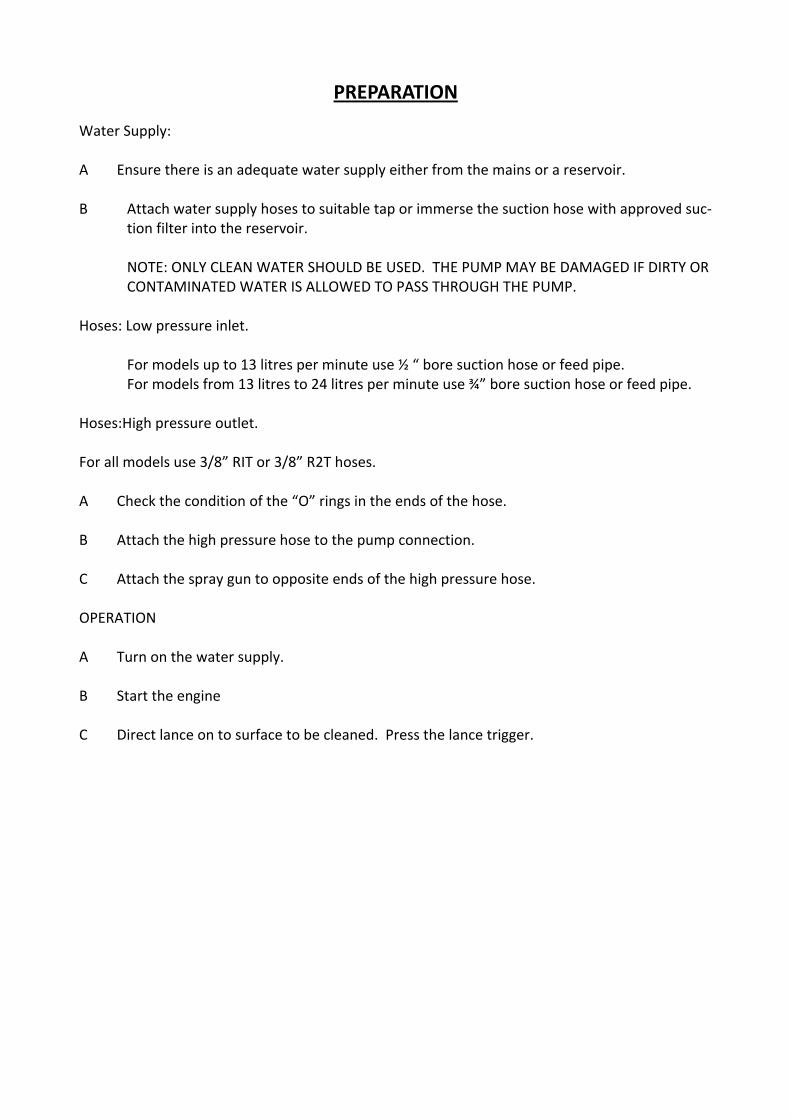
PREPARATION Water Supply: A Ensure there is an adequate water supply either from the mains or a reservoir. B Attach water supply hoses to suitable tap or immerse the suction hose with approved suc‐
tion filter into the reservoir. NOTE: ONLY CLEAN WATER SHOULD BE USED. THE PUMP MAY BE DAMAGED IF DIRTY OR
CONTAMINATED WATER IS ALLOWED TO PASS THROUGH THE PUMP.
Hoses: Low pressure inlet.
For models up to 13 litres per minute use ½ “ bore suction hose or feed pipe. For models from 13 litres to 24 litres per minute use ¾” bore suction hose or feed pipe.
Hoses:High pressure outlet.
For all models use 3/8” RIT or 3/8” R2T hoses. A Check the condition of the “O” rings in the ends of the hose. B Attach the high pressure hose to the pump connection. C Attach the spray gun to opposite ends of the high pressure hose. OPERATION A Turn on the water supply. B Start the engine C Direct lance on to surface to be cleaned. Press the lance trigger.
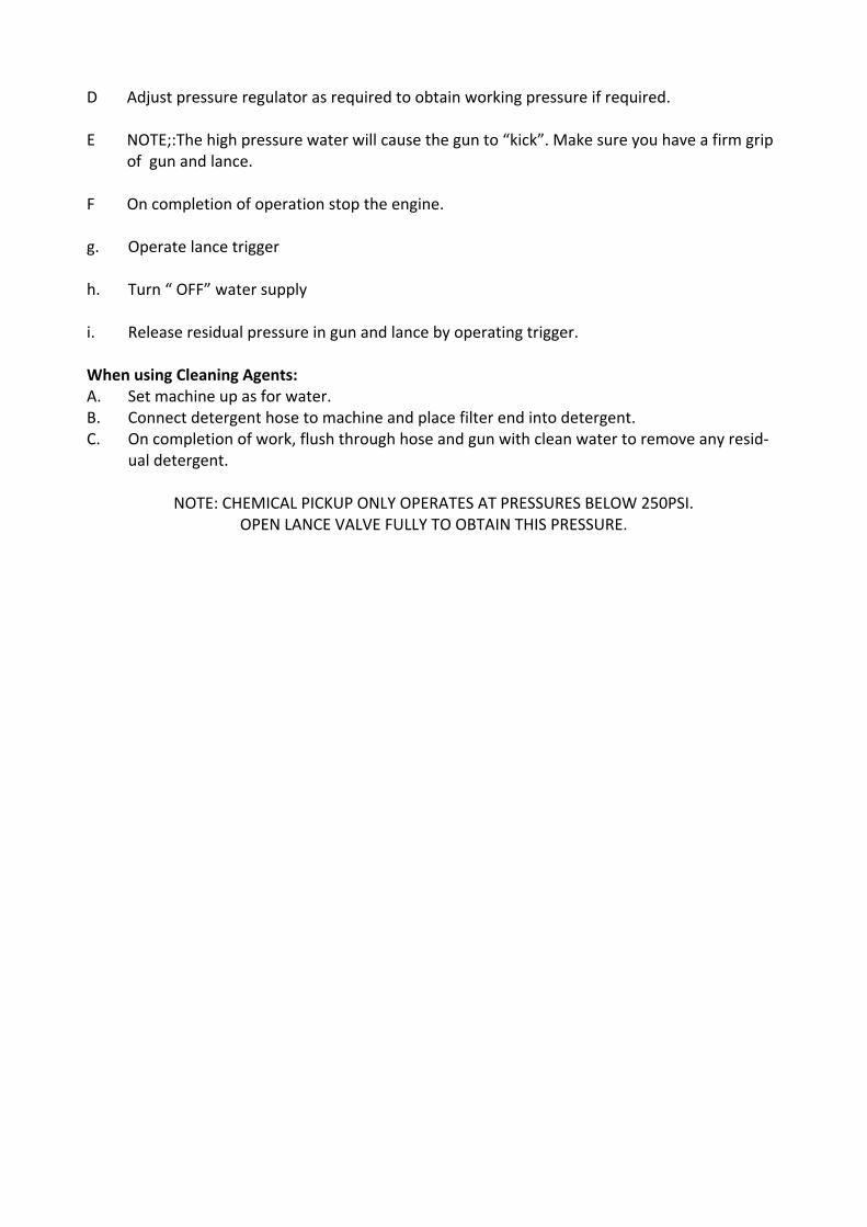
D Adjust pressure regulator as required to obtain working pressure if required.
E NOTE;:The high pressure water will cause the gun to “kick”. Make sure you have a firm grip of gun and lance.
F On completion of operation stop the engine.
g. Operate lance trigger
h. Turn “ OFF” water supply
i. Release residual pressure in gun and lance by operating trigger. When using Cleaning Agents: A. Set machine up as for water. B. Connect detergent hose to machine and place filter end into detergent. C. On completion of work, flush through hose and gun with clean water to remove any resid‐
ual detergent.
NOTE: CHEMICAL PICKUP ONLY OPERATES AT PRESSURES BELOW 250PSI. OPEN LANCE VALVE FULLY TO OBTAIN THIS PRESSURE.
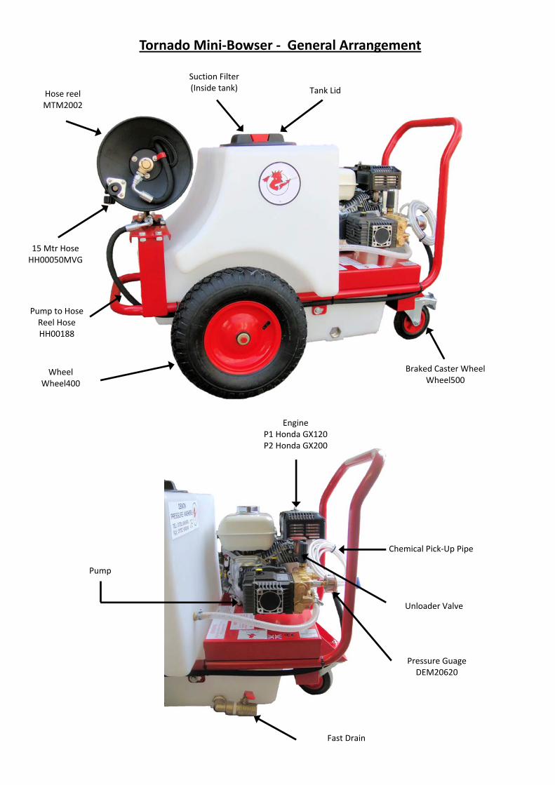
Tornado Mini‐Bowser ‐ General Arrangement
Tank Lid
Braked Caster Wheel Wheel500
Wheel Wheel400
15 Mtr Hose HH00050MVG
Hose reel MTM2002
Engine P1 Honda GX120 P2 Honda GX200
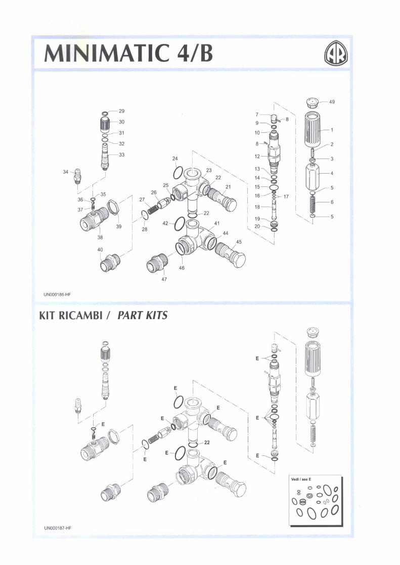
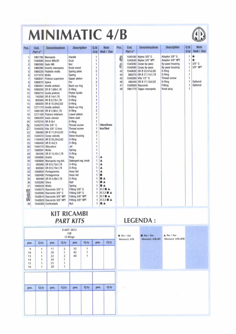
Unloader Valve
Chemical Pick‐Up Pipe
Pressure Guage DEM20620
Fast Drain
Pump
Suction Filter (Inside tank)
Pump to Hose Reel Hose HH00188
WARRANTY
This warranty covers the cost of all replacement parts and labour charges incurred, but does not cover the cost of transport or carriage. It is the owners responsibility to return the machine to a service depot or pay the travelling expenses of a engineer to attend. Demon Internationals decision in warranty matters is final and binding. Demon International Ltd, undertake to repair or replace at their discretion, any component which may fail due to a manufacturing fault within a period of 12months from the date of purchase, provided that any fault or damage was not sustained by; A Lack of regular and proper maintenance, user negligence, misuse, or damage caused by
ice or frost. B The effects of contaminated fuel or water, the use of non‐approved chemicals, or an in
sufficient or unsuitable electrical supply. C The effects of un‐authorised modification and use. D Compression damage to high pressure hose. ( Hoses are warranted for one month only) E Worn out items considered wear and tear. Parts which may or may not wear out during the first year and which are considered service items which will need replacing from time to time: High pressure nozzle, lance, trigger, hoses, fuel nozzle, fuel filter, piston seals, valves, unloader seats and seals, water filter, non‐return valve, chemical barbs, chemical pipes, and pump oil seals. It is the owners responsibility to ensure the pressure washer is kept in a safe and suitable envi‐ronment and any faults reported by operatives to be rectified at the earliest possible date. It is the operators responsibility to check the pressure washer for any faults and report them im‐mediately, and to use the pressure washer in accordance with the manufacturers specifications and guidelines. Demon International Ltd, undertake to use the highest quality components available during manufacture, but can not be held responsible for any undue consequence arising from the use of their pressure washers. This warranty is given the original purchaser only and is not transferable without the fully author‐ized and written consent of Demon International Ltd.
Warranty Procedure
End Users If your machine develops a problem: 1. Phone Demon for advice with the model and serial number to hand. 2. Describe fully the problem as best you can. 3. If the problem cannot be resolved over the phone then the machine can be booked in for repair and if the faults are covered by the warranty the repair will be carried out free of charge. 4. If you cannot bring the machine in for repair then we will despatch an engineer. If the fault is covered by the warranty then we will not charge for labour or spares used, however the transport charge will be payable weather or not the repair is warranty. Hire Centres and Dealers If your machine develops a problem: 1. Phone Demon for advice with the model and serial number to hand. 2. Describe fully the problem. 3. We will advise you on the best course of action, however if parts are required you must raise a purchase order number to cover the parts. When the parts are fitted they must be returned for examination before a credit note is issued. 4. If you are unable to repair the machine then we will despatch an engineer to carry out the repair. We will need a purchase order to cover the cost of transport to and from the site and for parts and labour if the repair is not covered under the warranty. 5. If required Demon will arrange for a carrier to collect a damaged machine, if the warranty claim is valid we will pay this cost, if not it will be charged to the customer. For parts warranty ring Demon and request a warranty claim form faxed to you. This form must accompany any returned parts. Notes: You will not invalidate the warranty by investigating faults and repairing them yourself providing you follow our advice. Hire Centres and Dealers are expected to carry out all repairs themselves with Demon crediting faulty parts upon receipt and inspection. Spare parts fitted to machines are guaranteed for 1 month only or the remainder of the war‐ranty period whichever is longer.
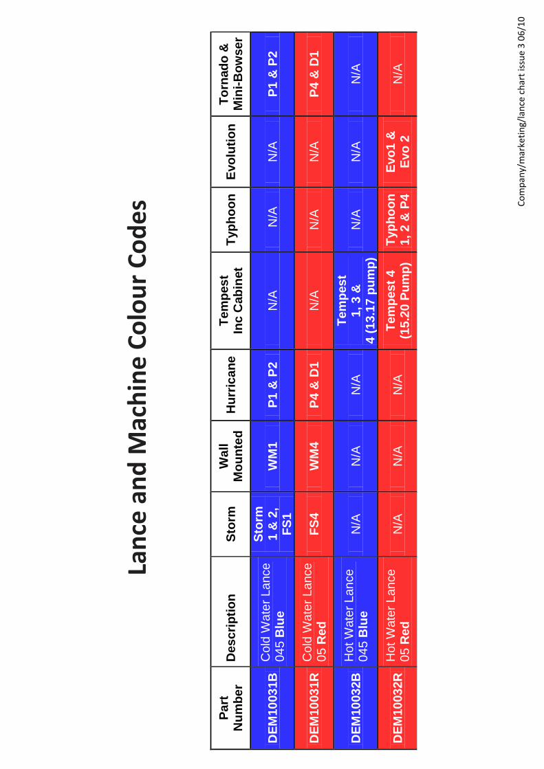
Lance an
d Machine
Colou
r Co
des
Part
N
um
be
r
Descri
pti
on
S
torm
W
all
Mo
un
ted
H
urr
ica
ne
Tem
pes
t In
c C
ab
inet
T
yp
ho
on
E
vo
luti
on
T
orn
ad
o &
M
ini-
Bo
wser
DE
M10
03
1B
C
old
Wate
r Lance
0
45 B
lue
Sto
rm
1 &
2,
FS
1
WM
1
P1 &
P2
N/A
N
/A
N/A
P
1 &
P2
DE
M10
03
1R
C
old
Wate
r Lance
0
5 R
ed
F
S4
WM
4
P4 &
D1
N/A
N
/A
N/A
P
4 &
D1
DE
M10
03
2B
H
ot W
ate
r L
an
ce
045 B
lue
N/A
N
/A
N/A
T
em
pes
t
1, 3 &
4 (
13.1
7 p
um
p)
N/A
N
/A
N/A
DE
M10
03
2R
H
ot W
ate
r L
an
ce
05 R
ed
N
/A
N/A
N
/A
Tem
pest
4
(15.2
0 P
um
p)
Typ
ho
on
1, 2 &
P4
E
vo
1 &
E
vo
2
N/A
Company/m
arketin
g/lance chart issue
3 06/10
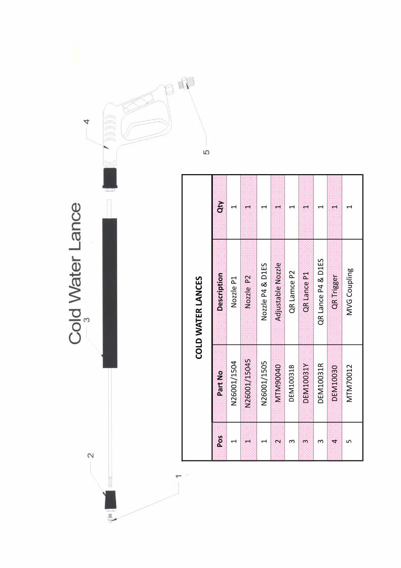
Pos
Part No
Description
Qty
1 N26001/1504
Nozzle P1
1
1 N26001/15045
Nozzle P2
1
1 N26001/1505
Nozzle P4
& D1ES
1
2 MTM
90040
Adjustable Nozzle
1
3 DEM
1003
1B
QR Lamce P2
1
3 DEM
10031Y
QR Lance P1
1
3 DEM
10031R
QR Lance P4
& D1ES
1
4 DEM
1003
0 QR Trigger
1
5 MTM
70012
MVG
Cou
pling
1
COLD
WAT
ER LANCE
S
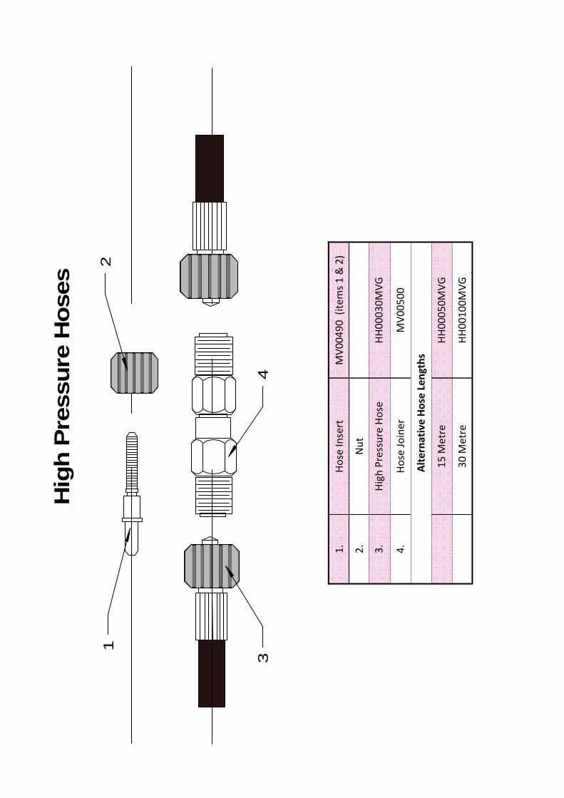
Hig
h P
ressu
re H
oses
12
34
1.
Hose Insert
MV0
0490
(ite
ms 1 & 2)
2.
Nut
3.
High Pressure Hose
HH00030M
VG
4.
Hose Joiner
MV0
0500
15
Metre
HH00050M
VG
30
Metre
HH00100M
VG
Alterna
tive
Hose Lengths
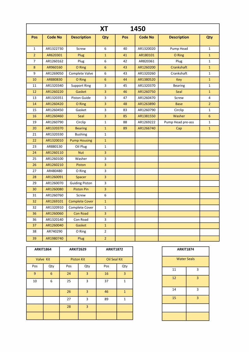
Pos Code No Description Qty Pos Code No Description Qty
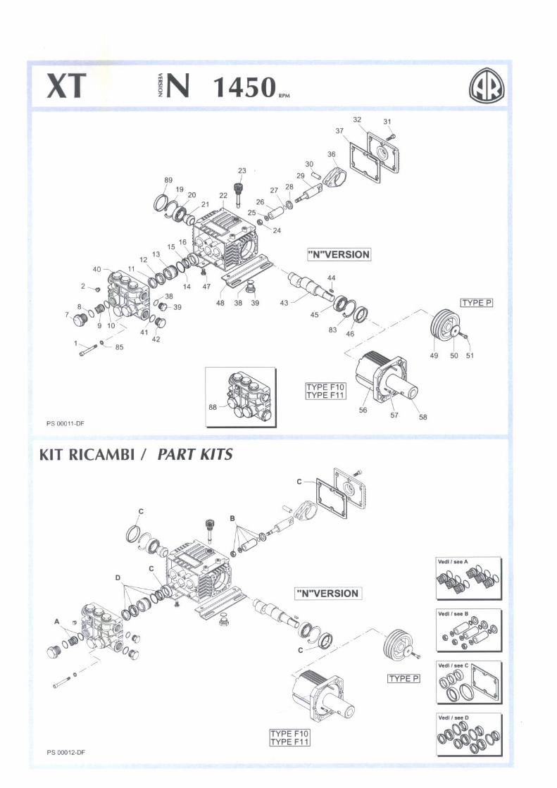
1 AR1322730 Screw 6 40 AR1320020 Pump Head 1
2 AR620301 Plug 1 41 AR180101 O Ring 1
7 AR1260162 Plug 6 42 AR820361 Plug 1
8 AR960160 O Ring 6 43 AR1260200 Crankshaft 1
9 AR1269050 Complete Valve 6 43 AR1320260 Crankshaft 1
10 AR880830 O Ring 6 44 AR1380520 Key 1
11 AR1320340 Support Ring 3 45 AR1320370 Bearing 1
12 AR1260220 Gasket 3 46 AR1260750 Seal 1
13 AR1320351 Piston Guide 3 47 AR1260470 Screw 4
14 AR1260420 O Ring 3 48 AR1263890 Base 2
15 AR1260450 Gasket 3 83 AR1260790 Circlip 1
16 AR1260460 Seal 3 85 AR1381550 Washer 6
19 AR1260790 Circlip 1 88 AR1269222 Pump Head pre‐ass 1
20 AR1320370 Bearing 1 89 AR1266740 Cap 1
21 AR1320330 Bushing 1 22 AR1320010 Pump Housing 1 23 AR880130 Oil Plug 1 24 AR1260110 Nut 3 25 AR1260100 Washer 3 26 AR1260210 Piston 3 27 AR480480 O Ring 3 28 AR1260091 Spacer 3 29 AR1260070 Guiding Piston 3 30 AR1260080 Piston Pin 3 31 AR1260760 Screw 6 32 AR1269101 Complete Cover 1 32 AR1320910 Complete Cover 1 36 AR1260060 Con Road 3 36 AR1320140 Con Road 3 37 AR1260040 Gasket 1 38 AR740290 O Ring 2
39 AR1980740 Plug 2
XT 1450
ARKIT1864 ARKIT2629 ARKIT1872
Valve Kit Piston Kit
Pos Qty Pos Qty Pos Qty
9 6 24 3 16 3
10 6 25 3 37 1
26 3 46 1
27 3 89 1
28 3
Oil Seal Kit
ARKIT1874
11 3
12 3
14 3
15 3
Water Seals