Embed Size (px)
Citation preview

~ y\Wlel~J- tor m ~cl~~T-«'h-~e#YS'
~~:::~: Stream Habitat Improvement Soul"m _ .. Ion Han d boo k Technical Publication RB-TP t6 June 1992
)

USDA Forest Service Southern Region
1720 Peachtree Road, N.W. Atlanta, Georgia 30367-9102
This handbook supersedes Technical Publication R8·TP 7. Fish /labilat Improve"""" Handbook. published January 1985.
The usc or trade names in this publication is for reader information and does not imply endorsement by the U.S. Department of Agriculture of any product Of service.
I inch I foot I mile
Common Measures and their Metric Equivalents
2.54 centimeters 0.3048 meter 1.6 kilometer
Persons of any race, color, national origin, se)C, age, religion, or with any handicapping condition are welcome to use and enJoy all racilities. programs, and services of the USDA. Discrimination in any form is slrictly against agency policy, and should be reported 10 the Secretary 01 Agricullure. Washington. DC 20250.
I

.J
)
)
STREAM HABITAT IMPROVEMENT HANDBOOK
INTRODUCTION
BY MONTE E. SEEHORN
Regional Fisheries Biologist
lIIustratiuns by Barry Nehr
TABLE OF CONTENTS
Page Purpose ..... ......... ..... . ... .... ... .. ...... ...... . ... ... . . . ..... ... ...... 2 Scope and Origin of Designs .... .. . ........................... . . . .... . ... . .... 2 Range of Habitat Conditions ................................. .. .. ..... ... .. ... 2 Principles of Stream Management ...... .. .. .. .. .. ........ . ...... . . .. . . ... .... . 2 Cost Estimates ................... . .... . . . ..... .. ........ .. .......... .. . ..... 2 Recordkeeping ............ .. ..... . ...... . ............ . .. ... ........... . ..... 3 Equipment and Supplies .. . ....................... . . . .. .... .... . .. .... . . . ..... 3
DESIGN SPECIFICATIONS AND APPLICATIONS
General Information . ...... .. . ... . .... . .. .... . . ... .. . ....... .. .... . .......... 3 Channel Block ............... .. .................. . ..... .... . . ....... ... ... 6, 7 Boulder Placement ......... . . . ........ . . . .. .. . ...... . ....... . ...... . ......... 8 Cover Logs and Rootwads ................... . ..... .. ...... . .... . ..... . .... 9, 10 Tree Cover .................. . ... . . ... . . ... . .... . . .... .. . .. ... . ......... 11, 12 Bank Crib with Cover Log . . . . . . . . . . . . . . . . . . . . . . . . . . . . . . . . . . . . . . . . . . . . . . . . . .. 13 Log and Bank Shelter .......... .. .... .... ... . . .. .. ..... . . ............... . 14, 15 Single-Wing Denector ....... . .. .. ... .. ... . ... . .... . .. . .... ............. .. 16, 17 Denector and Cover Log .................. . ............ .. ....... . ..... . .. 18, 19 Double-Wing Denector ..................... . ........ . ................... . 18, 19 Channel Constrictor ...... ... . .... .. ........ . . .. .... . . ........ ..... . ... ... .. 20 Cross Log and Revetment ......... ... ......... . ........ ...... . .............. 21 Wedge Dam ...... ........... .. .......... .. .. . ... . ..... .. .... ......... . . 22, 23 K Dam ... ......... . ... . ...... . .. .. ............ .. .. .. .. .... .. . ........ 24,25 Fish Barrier ................ . .... .. . . . .. ......... ... ... . ...... . ......... 26, 27
SUGGESTED READING .... .. ..... . ..... . ...... . ....... . .. .. .. . .............. 28
Construction Photos ................ . ............. . .................... . .... 29
1

2
INTRODUCTION
Purpose This handbook provides fishery managers with instream
structur~ design,s ~hat ~ay be used to correct andlor improve fish habItat defICienCies over a broad range of conditions. With the exception of the fish barrier, the primary objective of the desIgns IS to create deeper water, remove sediment by flushing action, add cover for fish, or add substrate and food for other aquatic organisms. Projects that add large woody debm often accomplish all these objectives.
Scope and Origin of Designs The majority of the designs are for structures that can be
installed with hand labor and tools. Others require heavy eqUipment to accomplish objectives. As a general rule , careful use of heavy equipment can significantly increase the n~mtx:r of structures installed in a given period of time. With httle or no added impact to the surrounding environment.
Most of the designs described are modifications of techniques from other stream-improvement publications. In prepanng thiS manual, designs were analyzed and selected to satisfy specific objectives. The original designs were then modificd , as needed, during field tests. Most of the tests ul?k place on trout streams in the Appalachian mountains of Vlfgtn ta, North Carolina, Tennessee, Kentucky, Georgia, and South Carolina. Limited tests were also made in warmwater streams in other States.
Sediment flushing and added depth are accomplished through scouring action. The scouring causes local movement of instream sediments and, at times , bank sediments. ~is should not be cause for concern, since long term benehts far outweigh any temporary adverse impads. Normally, ~uch local scouring adds little sediment. The primary effect IS to shift bedload matenal a short distance downstream, creating the beginning of another meander. As meanders inc~ease and t~e gradient decreases, current velocity and sedlment-carrytng capacity are reduced. Creation of these stream meanders, along with deeper water and improved cover, can mean the difference between marginal aI1d beUerthan-average fisheries. In shallow streams where flow sinks into deep gravel or rubble deposits during drought periods, creation of deeper water or holding pools can be critical.
Cover includes the addition of boulders, logs, rootwads, or any other material that creates hiding or resting areas for fish.
The addition of woody debris, where lacking, can accomphsh the above objectives while providing substrate andlor food for other aquatic organisms. Systems such as lowgradient, sandy, coastal-plain streams are especially dependent upon large woody debris to provide suitable conditions for fish and other aquatic communities.
Range of Habitat Conditions Habitat conditions range from steep gradient reaches (300
to 500 feet per mile) in which the primary substrate is boulders and large rubble, to very low-gradient reaches (less than 10 feet per mile) with shifting-sand substrate.
Stability of slreams ranges from excellent to very unstable, depend 109 upon physiographic region. Stream channels
~ within some provinces may change characteristics after each major flood due to extensive bedload movement.
The wide range of conditions encountered throughout the South likely include situations similar to those found in other regions. Therefore, structures suitable for a IS-foot
wide, 3-percent gradient, gravel-bottom stream in the South would probably be suitable, with minimum modification for streams with similar characteristics elsewhere. '
Principles of Stream Management Techniques for improving habitat should be based upon
overall management goals of the fishery resource. When the goa! ~s to improve a fishery for large resident brown trout, additIOn of overhead cover should receive highest priority. When the overall goal is maximizing "put-and-take'· fisheries, the addition of structures that will create large open pools may be highest pnonty. An anadromous fishery requirmg maximum spawning habitat development would need yet another approach.
When setting goals, consider not only the target species, but als? the aSSOCiated community organisms and overall aesthettcs of the program. Diversity is important in most ecosystems; therefore design your projects to meet the broadest habitat requirements that can be encompassed while still meeting basic objectives. In some projects, aesthetics may be the primary consideration when selecting structure design. For example, wedge dams, K-dams, and double-wing deflectors are used to create scour pools. Under certain conditions, any. one of these designs, used exclusively, would likely achieve fish productIon goals. However, overall aesthetics and diversity objectives would best be met if all three designs are used in a single project. . Economics must also be assessed. Few people enjoy delv-109 mto thIS aspect of a project, yet it is an essential task that must be addressed in order to determine project viability.
Proper planning is critical in any management program. The following action plan provides a logical sequence for Implementatlon:
(I) Establish goals and objectives. (2) Examine and identify existing conditions and limit
ing factors. (3) Prescribe methods to correct deficiencies. (4) Treat by prescription . Base priorities upon overall
management objectives. (5) Evaluate project to determine if short-ternl goals
are met. (6) Maintain projects to ensure completion of long
term goals.
Cost Estimates Cost estimates are given in crew days (8 working hours) ,
rather than dollars to keep your calculations on a current basis in any time period. They are based on a four to sixperson crew working in relatively accessible areas using handtools , and cutting logs on site . Installation at times ?ther than low flow periods increases cost and reduces qualIty of the fintshed product. Use of heavy equipment in larger streams can sLgmflcantly increase the number of structures installed at a given time.
St~cture durability varies significantly, depending on tree species used, stze of logs, and the extent the structure is exposed to air. Logs from small, fast-growing trees , contain-109 little heartwood, deteriorate rapidlY· Older trees with a high percentage of heartwood, and rot-resistant species such as black locust and eastern hemlock, arc most su itahle when ~xposure to air is a problem . When submerged, all species mcludmg yellow-poplar, oak, and white pine are relatively durable. Yellow pine is less durable, but is acceptable in the ?bsence of other species. (The species listed above are found m the South and may not be available elsewhere.)
)
I
)
)

)
)
With proper installation and occasional maintenance, all structures discussed in this handbook should provide benefits for a minimum of 20 years. A few structures placed by Civilian Conservation Corps crews in the 1930' s were still in place and functioning after 50 years.
Recordkeeping Recordkeeping is an important, but sadly neglected, aspect
of habitat improvement programs. Due to the dynamic nature of watercourses, it is especially important to keep detailed records of stream habitat work. Occasional maintenance is a necessity and requires specific information about location and design of each structure. A simple form, such as that shown in figure I, provides space for recording locati?n, design details, materials used, cost estimates, evaluation information, and maintenance performed on individual structures. In addition, a sketch (figure 2) of the entire project is invaluable to maintenance crews and other personnel for determining structure location.
Equipment and Supplies The following list describes hand-operated equipment use-
ful to a stream improvement crew: -Chainsaw. -Chainsaw winch. -Hand winch ("come-along"). -Cobra, Pionjar, or similar heavy but portable jackham-
mer for driving steel or drilling rock. -Hilti or similar lightweight drill for drilling rock or logs. -Cable and epoxy for attaching logs to rock substrate. -Heavy wire, such as hogwire or chain link fencing (36-
to 42-inch width). -Fiberglass cloth or fine-mesh wire, such as hardware
cloth, for use with the heavy wire. -Planking as an alternative to the heavy wire and fiber
glass cloth. -Staples for attaching wire and cloth to log. -Handtools such as clawhammer, axe, mattock (2), pick,
5- to 6-foot steel pry bar (2), shovel (2), fire rake (2), sledgehammer (2), 50-foot fiberglass tape, peavy (2), log carrier (one per two crew members), wire cutters, pliers, cable and clamps, fencepost driver, rebar "driving head", hacksaw.
-Logs - Size of logs will vary with size of stream and type structure. Whenever available, use logs 14 to 16 inches or more in diameter.
-Steel pins in two sizes cut from reinforcing rod (rebar), and sharpened on one end:
3/4-inch rebar cut 18 inches or longer (depending on log size) for pinning logs together.
3/4-inch rebar cut 54 inches or longer depending on stream size and substrate stability for anchoring logs to the substrate.
DESIGN SPECIFICATIONS AND APPLICATIONS
General Information As mentioned in the previous section, size of logs depends
somewhat on stream size. On shallow streams less than 12 feet wide, 10- to 12-inch logs may be suitable. As a general rule, however, logs should be at least 14 to 16 inches or more in diameter. In this type work, the axiom "bigger is better" usually applies!
The distance logs are dug into the streambank depends on bank stability characteristics. In the most stable situations, where logs can be locked behind boulders or root systems, a distance of 3 to 4 feet may be adequate. When banks are composed of unconsolidated gravel, rubble, or other unstable material, a distance of 10 feet or more may be reqUIred. Under these conditions, heavy equipment (front-end loaders, backhoes, etc.) may be needed for excavation.
In some situations, logs can be anchored with no excavation by sharpening one end with a chainsaw and driving them into the bank with a bulldozer or other heavy equipment. Abutment logs, or rootwads with the bole attached can be driven as much as IOta 12 feet into the banks, resulting in complete stability with a minimum of disturbance. Use of these techniques disturbs the soil much less than do hand tools requiring excavation of trenches for the logs. As might be expected, size of logs or rootwads used is limited by size of available equipment. A D-6 Caterpillar or other similar-size equipment will, in most cases, be needed to drive logs in the 14- to 20-inch range. Smaller equipment such as a John Deere 450 or Caterpillar D-4 will, however, handle logs up to a 14-inch diameter in soft banks.
Some banks are rocky for "driving", or may involve,' bedrock. At such sites, anchor the logs by drilling the rock' and driving rebar into the holes or placing cable over the logs and then epoxying the ends into the drilled holes.
Use short rebar to join logs. Use longer rebar to anchor logs into the stream bottom. A cutting torch can be used to shape points on these steel pins. Cut a slot or hole through the logs to facilitate driving them. A chainsaw is the simplest and quickest tool for cutting a slot. A power drill may be needed to drill holes through extremely hard wood such as black locust.
A soft, rolled-steel cylinder 6 inches long by 2 inches in diameter with a 7/8- or I-inch diameter hole drilled 3 inches deep into its length, can be used as a "driving head" for the pins.
Low-flow periods are optimum for structure site selection and installation. In the South, this generally occurs during late summer and early fall, although suitable conditions can occur any time from May through early November.
( )
3

4
STREAM IMPROVEMENT ST~UCTURE
NATIONAL FOREST /Va I) fa ba/a.... DISTRICT @'1tLA Stream Bitt Il')dl4.1'} Cr. Structure 11-,-1 __
Locat10n of structure hI-51 stl-uCTVfe above TAe-('?~{)1j 01 'Srr S~ql c/-. (o/jJMj.IOO/)
Type st-ructure We d% dam Dat-e of construction 5(;otI7f'~
Materials used lIemloc,f /t:Jf.5t #PfW1J.e., ;V'dr0 e/t;/d Man days (, est.imat-ed cost- of struct-ure 3 /Y}4n ~IfS - BJSO , Purpose of structure 70 CH?41e a. PCJo/1= Im/JfC)Ve /)';',4 cove;..
) F
Evaluat-ion of struct-ure at- least- one year aft-er construct-ion ~AtlC~{)~ h4~ ljeq!ea' a. ,PtJo/ 30// da?!' in a. stretc;.h ~I' wM?1-nOf.1?14//y olJly a.../ew I;'d~s deep
Maint-enance performed (date 6. IJnef description) #0 (YltllnJenal'Jce 10 d~k (6/'1;1..). Only woNt needed at pre.sel1t ;'s mlnCJJ- ;.eP/4ceme'lt c;-/' I-octt"s il? w/nfs (see stetcA).
Top VieN SKETCH
" / , , , , , / , , ,
View from downstream side
=,~;::::q..--r-....p;;:~ - - - - -,-', ~----t=:::: I: _____ .... ' '.../. ---
Figure 1.-Example of record form.
)

)
)
l ( { ) Hwy 49
(,
CD '-'. installed 1986~ .: ......
installed 1986-
installed 1986 *' o
tv (..~
installed 1987
0·:-\ ,
washed out 1989
'<'v~ -"~
, C).. , \ , '. •• 1 ~
*'
......... ""'0 -::- installed 1986 '..l
Figure 2.-Kramer Creek stream improvement project.
( )
5

6
Figure 3.-Channel blocks.
Channel Block Purpose - In any improvemenl project. top priority should
generally be given to consolidating braided channels. Low summer flows moving through several small channels hold fewer large fish and in some cases will not allow up or downstream movement of fish. By consolidating flow into a single. deeper channel. additional fish-holding habitat can be created. In addition. potential temperature problems can be avoided (wide, shallow areas tend to warm quickly), and migration routes restored.
These structures may also be used to maintain stream meanders where flood flows have eroded a channel through the meander (figures 3 to 5). The structure holds normal or
, moderately high flows in the meander channel, but still
) } . llows flood waters to overflow into the blocked channel.
r Design - Since these structures are placed in critical areas bearing the brunt of flood waters, special care must be taken to ensure stability. Single logs may be used with success in
small streams. Triple log and crib structures give better results and are less likely to wash out in larger (over 15 feet wide) streams. Generally, triple logs can be used in relatively stable streams 15 to 25 feet wide. The log crib, filled with gravel and rubble, is generally more suitable for larger, unstable streams.
Placement - Channel blocks are usually installed in braided channels or in stream meanders where flood waters are creating an oxbow. Place blocks at the lower end of the flood channel as well as the upper end, to prevent head cutting.
Advantages - Triple logs or cribs tend to leak less waler than do single logs. However, single logs are much easier
j)
and cheaper to install. JJ Cost - Generally. three to four single-log structures or
two to three triple-log structures can be installed per crew day in 15- to 20-fool wide channels. One hand-filled crib may require from I to 2 days to conslruct.

(
, Figure 4.-Channel block - single log. , f .
.i
Figure 5.-Channel block - crib.
7

)
8
Boulder Placement Purpose - The primary goal is to provide overhead cover
and rcsling areas. Added depth is also created by scouring resulting from reduced channel capacity and increased current ve locity_
Design - For best results, use large, irregular-surfaced boulders. The more irregular the surface, the more "pocket" or hiding space will be available to fish. Where channel width allows, best results are obtained by placing the boulders in groups (figures 6 to 8).
Placement - Boulders can be used in most stream situations, including riffles, runs, flats, glides, and open pools.
Greatest benefits are likely to be achieved in currents exceeding 2 feet per second.
Advantage - No other materials are needed for installation. Boulders also present a more natural appearance than do most structures.
Disadvantage- Boulders are not always available at project sites. Heavy equipment may be necessary to move them into place.
Cost - Cost depends upon the distance boulders are moved and the type of equipment used. If conditions are suitable and boulders are plentiful , a frontend loader could easily place 25 or more a day.
J l r~I. ________ F_lg_u_re __ 6_~_B_o_u_ld_e_r_p_la_ce_m __ en_t_, ________________________________________ ~

Cover Logs and Rootwads Purpose - These structures provide overhead cover in
sections of stream where existing water depth may be adequate. but cover is lacking. Sec figures 9 to 16.
Design - Cover logs can be any shape. length. or size. but best results are attained with large (over 16 inches diameter). crooked logs. They provide an irregular surface. resulting in maximum turbulence along the cdge of the log. Logs with stubs of limbs several inches long create additional turbulence and spot scouring. Large stumps or rootwads. if available. provide ideal cover. Where such material is unavailable and logs are small and straight (use nothing less than 10 inches). a slab can be chains awed from the bottom. creating a "bench" effect (figure 10).
Logs placed out in the channel can be pinned into gravel and rubble substrate with 3!4-inch rebar 54 inches or longer. Logs placed against streambanks can be anchored with rebar as mentioned above. or pinned to abutment logs in the bank. Where bedrock is prevalent, use a portable jackhammer to drill holes. Logs can then be attached with rebar driven through and into the hole. or with cable and underwater epoxy.
Install abutment logs by excavating trenches or drive them into the bank with heavy equipment. Drive root wads with 8-to 12-foot boles flush with the streambank (figure 9). If the bank is unstable. place logs across the rootwad boles. against the bank. as shown in figure 9. and pin them. "Footer" logs underneath the boles may be needed in highly unstable streambank material.
Placement - Ideal locations are open pools. runs. or flats at least 6 to 8 inches deep (preferab ly deeper). In these locations. logs are placed parallel . or at a slight angle. to the flow (figure 10). Logs installed along stream banks are ( usually placed at a slight angle to flow. The best bank locations are in stream meanders or in conjunction with deflectors (see "Deflector and Cover Log").
Advantage - Cover logs and rootwads are the simplest and least expensive of the log structures discussed. Under certain conditions they provide optimum cover and present a natural appearance. In addition. they arc suitable for use in any size stream, and have Jess impact on channel capacity and flow characteristics than do other structures. Maintenance is minimal.
Disadvantage - Unless logs are large and of irregular shape. they may become partly or completely covered with sediment deposits. Benefits may be minimal in water less than 6 to 8 inches deep. In sandy or other highly unstable substrate. there may be no feasible means of anchoring them. other than into the streambank.
Cost - When logs are handy and rebar is used to anchor them into the substrate, a crew can install 10 or more cover logs per day. Where abutments must be dug into banks to hold them in place. less than 10 structures per day is a more realistic goal. A two- or three-person crew with a dozer can coliect and install six to eight or more rootwads per day.
cahle epoxied Info bed J-OC}<.
; )
)
Figure g.-Cover logs and rootwads. Figure 10.-Cover logs and rootwads.
9
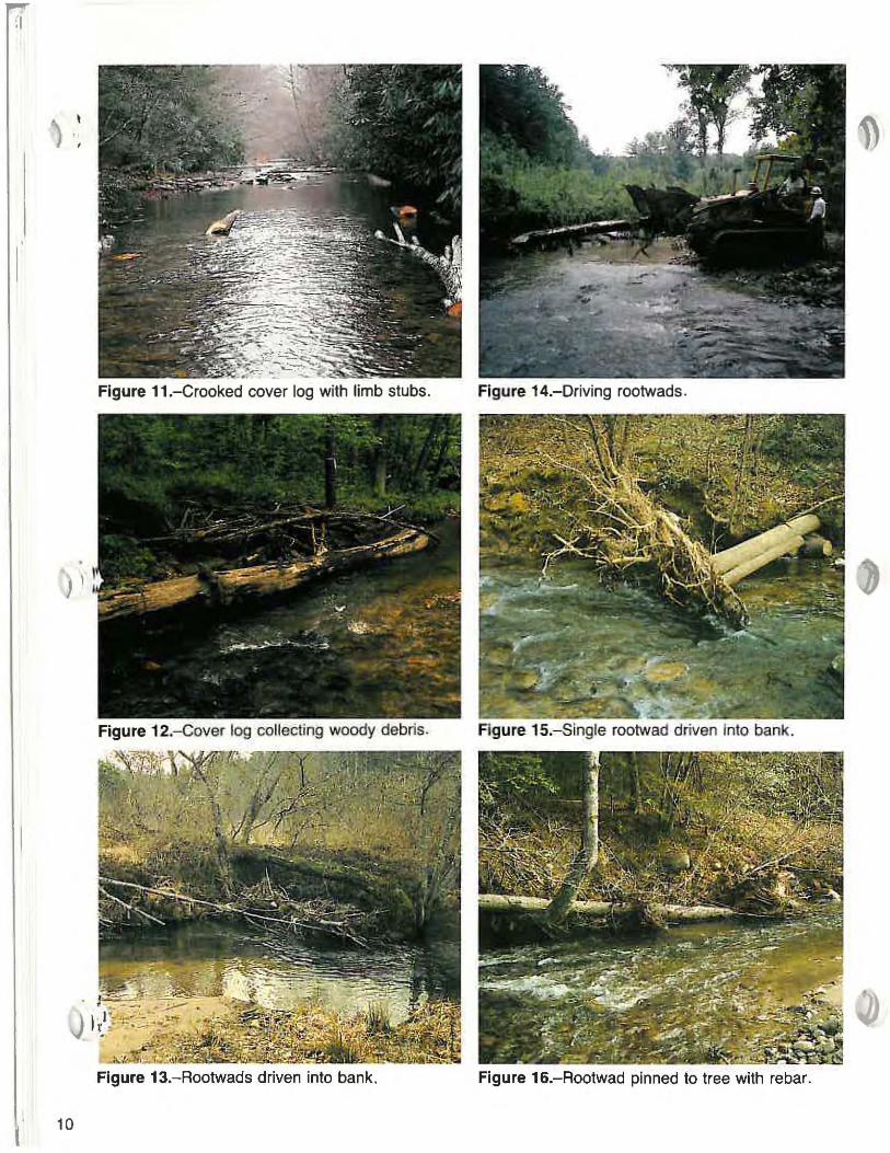
Figure 11.-Crooked cover log with limb stubs. Figure 14.-Driving rootwads.
Figure 12.-Cover log collecting woody debris. FJgure 1S.-Slngle rootwad driven Into bank.
Figure 13.-Rootwads driven into bank. Figure 16.-Rootwad pinned to tree with rebar.
10

Tree Cover Purpose - Trees placed in proper locations provide sev
eral benefits. They provide excellent overhead cover and an ideal substrate for aquatic organisms. [n addition, trees serve as deflectors constricting wide, shallow channels, thus increasing stream velocity, resulting in sediment flushing and deeper scour pools.
Design - Trees can be cut and felled directly into the stream (in a downstream direction) with the axis parallel or at a 10- to 20-degree angle to the stream bank. If trees are located properly, they can be hinge-felled in place (figure 17). Where trees are hinge-filled, they can also be cabled to the stump to ensure stability. If not, they can be cut, placed, and then attached with cable to the stump (figure 18). In smaller streams, understory shrubbery, such as rhododendron, can be hinge-felled in the same manner as trees. If heavy equipment is available, entire trees including rootwad can be uprooted, moved, placed, and anchored to abutment logs driven into the streambank (figures 19 to 21). These
Ct>b'fe. fo 9vmJ'
Figure 17.-Tree Cover.
placements give a natural appearance and provide ideal cover for fish, and substrate for other aquatic organisms.
Placement - Place trees or shrubs in any section of stream large enough that such installation will not create serious ( bank erosion. Greatest benefits probably occur in wide, shallow streams with sand or gravel substrate.
Advantage - Under certain conditions trees can provide excellent benefits with little expense. [n larger streams with unstable substrate and no means of attaching cover logs, trees may be the only feasible alternative;
Disadvantage - Small channels may preclude the use of trees. Suitable trees may not always be nearby. Where trees cannot be felled directly into the stream, heavy equipment will be required for placement.
Cost - Where trees can be hinge-felled or dropped in place, two workers could cut and cable eight to twelve trees per day. Where trees must be moved by heavy equipment, four to eight trees per day would be a more reasonable figure.
i \ !
Figure 18.-Tree Cover.
Figure 19.-Tree Cover.
)
11

) \
Figure 21.-Tree cover.
12

Bank Crib with Cover Log Purpose - Protects unstable banks; at the same time pro
vides excellent overhead cover for fish . Design - A simple crib with abutment logs should extend
as far back into the bank as necessary to assure structure stability (4 to 6 feet in stable soils and 10 feet or more in unstable soils). Put the lower abutment logs near water level (figure 22) and extending 18 to 24 inches from the bank. The cover log can then be pinned to the crib log and the lower abutment (figure 23) . The structure can be from one to several logs high. depending on bank height (figure 24) .
Placement - This structure can be used in any area with unstable banks.
Figure 24.-Bank crib.
Advantage - The design accomplishes two objectives. It ensures bank stability and creates excellent cover at the same time. The only materials required are logs on site and rebar to join them. (
Disadvantage - Installing the structures is fairl y timeconsuming, due to the amount of digging required. Eroding banks at some locations require abutment work, but the water is too shallow to make effective use of cover logs.
Cost- One crew should install 20 to 30 feet of crib (two crib logs high) per day if logs are reasonably close to the site . Use of heavy equipment to drive abutments and place crib logs can increase output four- to fivefold.
Figure 22.-Bank crib with cover log.
\ .. , Ii 'WIA '; '}4' Reb4r ~)J !
'--
,,--"'1-£It-_ - ---- _ -~~*-----_/
~:"!::!2't:4~ - - - -.. ')
-- - _ ....
Figure 23_-Bank crib with cover log, side view.
. I , f ~
13

14
Log and Bank Shelter Purpose - Provides overhead cover. Some streambank
protection is also provided. although less than with cribs. Brush and other woody material attached to the platforms provide additional benefit by harboring insects and other fish food organisms.
Design - The finished shelter is a form of cover log spanning a stream meander with a choice of various materials to create a shelf. The materials used to cover the space between the main log and the bank can consist of rock. logs. Or simply brush. Figures 26-28 and figures 29-31 illustrate two different techniques in cODstructing the shelf. In figures 26-28 dig or drive the abutment logs and the ends of the main log into the bank and then pin them together with rebar. The structure will last longer if all logs are submerged. Attach brush or debris so that portions are above and below the water surface.
. , I r .,i.. J I'
Figure 25.-Log and brush shelter.
Placement - These structures are most suitable for use in low-gradient stream bends or meanders where open pools are already present. Use them with a deflector to cnhance results.
Advantage - Materials are cheap. and a comparatively large area or overhead cover is provided at each site. Brush provides maximum surface for hoth terrestrial and aquatic insects.
Disadvantage - Where streambanks are high, use of hand tools to excavate channels for the logs can be very labor intensive. Use of heavy equipment to simply shove the logs inlo the bank, however, can make this one of the more cost-effective designs.
Cost - Output should range from two structures per crew day on a small stream with low banks (2 to 4 feet) to one per day On larger streams with higher banks. Use of heavy equipment to drive and place logs can increase output fourto fivefold .

Figure 26.-Placing abutment log on main log.
Figure 27.-Adding slab rock and tamping bank.
Figure 28.-Log and bank shelter 6 weeks after installation.
Figure 29.- Driving 12' logs for bank
Figure 30.-Adding planks for shelf.
Figure 31.- Shelf with rock added 6 weeks after Installation.
(
15
Single-Wing Den.etor
) '
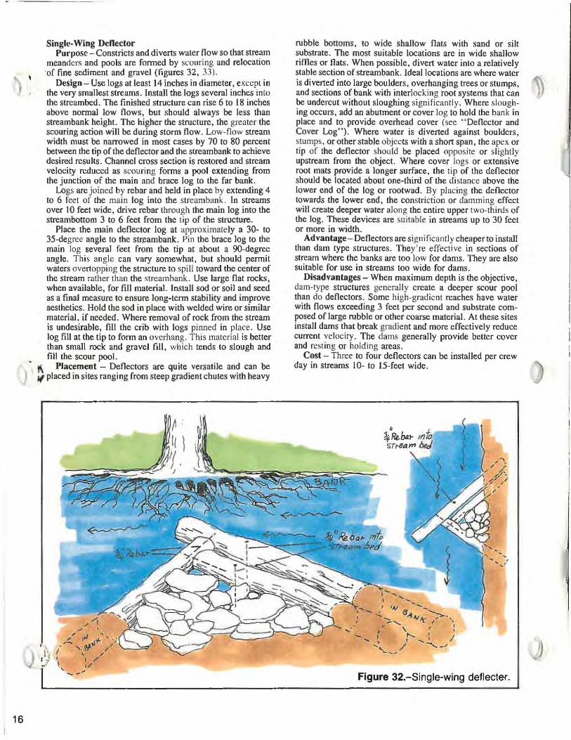
Purpose - Constricts and diverts water flow so that stream meanders and pools are formed by scouring and relocation 'of fine sediment and gravel (figures 32, 33).
Design- Use logs at least 14 inches in diameter, except in the very smallest streams. Install the logs several inches into the streambed. The finished structure can rise 6 to 18 inches
16
above normal low flows, but should always be less than stream bank height. The higher the structure, the greater the scouring action will be during storm flow. Low-flow stream width must be narrowed in most cases by 70 to 80 percent between the tip of the deflector and the streambank to achieve desired results. Channel cross section is restored and stream velocity reduced as scouring forms a pool extending from the junction of the main and brace log to the far bank.
Logs are joined by rebar and held in place by extending 4 to 6 feet of the main log into the streombank. In streams over 10 feet wide, drive rebar through the main log into the streambottom 3 to 6 feet from the tip of the structure.
Place the main deflector log at approximately a 30- to 35-degree angle to the str.eambank. Pin the brace log to the main log several feet from the tip at about a 90-degree angle. This angle can vary somewhat, but should permit waters overtopping the structure to spill toward the center of the stream rather than the streambank. Use large flat rocks, when available, for fill material. Install sod or soil and seed as a final measure to ensure long-term stability and improve aesthetics. Hold the sod in place with welded wire or similar material, if needed. Where removal of rock from the stream is undesirable, fill the crib with logs pinned in place. Use log fill at the tip to form an overhang. This material is better than small rock and gravel fill, which tends to slough and
• fill the scour pool. , 1'\ Placement - Deflectors are quite versatile and can be
I " placed in sites ranging from steep gradient chutes with heavy
-
rubble bottoms, to wide shallow flats with sand or silt substrate. The most suitable locations are in wide shallow riffles or flats. When possible, divert water into a relatively stable section of stream bank. Ideal locations are where water is diverted into large boulders, overhanging trees or stumps, ~, and sections of bank with interlocking root systems that can IJ be undercut without sloughing significantly. Where slough-ing occurs, add an abutment or cover log to hold the bank in place and to provide overhead cover (see "Deflector and Cover Log"). Where water is diverted against boulders, stumps, or other stable objects with a short span , the apex or tip of the deflector shou ld be placed opposite or slightly upstream from the object. Where cover logs or extensive root mats provide a longer surface, the tip of the deflector should be located about one-third of the distance above the lower end of the log or rootwad. By placing the deflector towards the lower end, the constriction or damming effect will create deeper water along the entire upper two-thirds of the log. These devices are suitable in streams up to 30 feet or more in width.
Advantage- Deflectors are significantly cheaper to install than dam type structures. They're effective in sections of stream where the banks are too low for dams. They are also suitable for use in streams too wide for dams.
Disadvantages - When maximum depth is the objective, dam-type structures generally create a deeper scour pool than do deflectors. Some high-gradient reaches have water with flows exceeding 3 feet per second and substrate composed of large rubble or other coarse material. At these sites install dams that break gradient and more effectively reduce current velocity. The dams generally provide better cover and resting or holding areas.
Cost - Three to four deflectors can be installed per crew day in streams 10- to 15-feet wide.
Figure 32.-Single-wing deflecler.

(
Figure 33.-Single-wing deflecter.
J
Figure 34.-Deflecter and cover log.
17

j ...
)
18
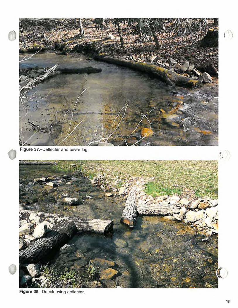
Deflector and Cover Log A deflector and cover log is similar to a single-wing
deflector. The cover log ensures bank stability where suitable boulders, tree stumps, or stable banks are lacking (figures 34, 35, 37). Two to three deflector-cover log combinations can be installed per crew day in streams 10 to 15 feet wide.
Double-Wing Deflector Purpose - Creates midchannel pools through scouring
action in shallow sections of streams . Design - This combination of structures includes two
singlewing deflectors placed on opposite streambanks (figures 36, 38) with the two apexes narrowing the low-flow channel by as much as 80 percent (i.e., a 20-foot wide channel would be narrowed to 4 feet between tips of deflectors). This degree of constriction in gravel and small rubble usually results in a scour pool extending 2 to 3 feet under the tip of each deflector as channel cross section returns to equilihrium.
I \ . , i<!
Placement - This combination of structures is especially suitable for shallow sections of stream where the gradient is too steep for effective deflector and cover log combinations , and where banks are too low to install wedge or K dams.
Double-wing deflectors can also be used in low-gradient ~ sections. but in most cases the small meanders created in " such areas by a series of deflector-cover log combinations provide better results than can be attained with double-wing deflectors.
Advantage - The double,wing deflector is suitable for use in situations where deflector-bank logs and small dams are not as effective or feasible . If installed properly, scour pools equal in quality to those produced by small dams can be created at less cost.
Disadvantage - These structures provide only one break in gradient or resting area (the scour pool). In contrast, dams often provide a small flat or resting area above the structure in addition to the plunge pool.
Cost-The paired structures can, in most cases, be installed at two locations per crew day in smaller streams (10 to 15 feet wide). In large streams, one and one-half structures per day is more realistic,
J ' ~ . .;;.I) ___ F_I_9_u_re_35_,_-_D_e_fl_ec_t_e_r _a_nd_c_o_ve_r_I_O_9_' ______ F_i_9_u_re_36_,_-_D_O_u_b_le_-w_i_n_9_d_e_fl_e_ct_e_r. __ ----'
(
Figure 37.-Deflecter and cover log.
Figure 3B.-Double-wing deflecter.
19

20
Channel Constrictor Purpose - Serves as a modified denector designed to
create overhead cover similar to that provided by undercut . banks. ", Design - Install channel constrictors alone or in pairs. ( Each structure consists of a main channel log and two bf'dce
logs (figures 39 to 41). Place the main log at a slight angle to now. Pin the two brace logs to it at a 45-dcgree angle. The main log can be from 10 to 30 feet long and should be as large as can be handled. A rough, crooked log often creates ideal cover. The intent is to provide an undercut for the entire length of the main log (both logs if structures are paired). On smaller logs, where overhang is not created through sheer size, cut a slab from the underside of the log to provide additional space (see "Cover Log").
Put at least two fill logs behind the main channel log (figure 39). Rock fill placed against the channel log tends to slough as the bottom scours, filling and reducing fi sh holding area,
Figure 39,-Channel constrictor.
Reduce channel width by 70 to 80 percent between the two main logs (where two structures are paired opposite). Allow slightly less distance between the lower ends than the upper ends . Where banks are unstable , it is critical to keep , structure profiles as low as possible . II
Placement - Channel constrictors provide best results when placed in long. straight. low-gradient stretches of stream.
Advantage - Constrictors provide more extensive overhead cover than do conventional denectors.
Disadvantage - Considerable experience is needed to install these structures properly. In most cases, failure has resulted from being too conservative when constricting the stream channel, and placement in reaches with excessive gradient.
Cost - One pair of structures per day is a reasonable goal.
Figure 41.-After channel constrictor installed (18- to 20-inches deep).
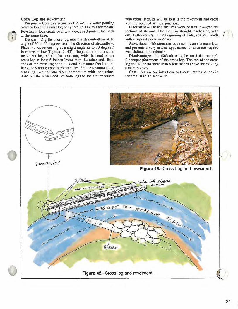
Cross Log and Revetment Purpose - Creates a scour pool formed by water pouring
over the top of the cross log or by forcing its way underneath. Revetment logs create overhead cover and protect the bank at the same time.
Design - Dig the cross log into the streambottom at an angle of 30 to 45 degrees from the direction of streamflow. Place the revetment log at a slight angle (5 to 10 degrees) from streamflow (figures 42, 43). The junction of cross and revetment logs should be upstream, with that end of the cross log at least 6 inches lower than the other end. Both ends of the cross log should extend 3 or more feet into the bank, depending upon bank stability. Pin the revetment and cross log together into the streambottom with long rebar. Also pin the lower ends of both logs to the streambottom
t J)ova,1a i/ed
with rebar. Results will be best if the revetment and cross logs are notched at their junction.
Placement - These structures work best in low-gradient sections of streams. Use them in straight reaches or, with (' I even'better results, at the beginning of wide, shallow bends with marginal pools or cover.
Advantage- This structure requires only on-site materials, and presents a very natural appearance, It does not require well-defined streambanks.
Disadvantage -It is difficult to dig the trench deep enough for proper placement of the cross log, The top of the cross log should be no more than a few inches above the existing stream bottom.
Cost - A crew can install one or two structures per day in streams 10 to 15 feet wide,
Figure 43.-Cross Log and revetment.
J?e6a~ ;,,10 F;!kam " ""tI'om =-= ~
, " .
Figure 42.-Cross log and revetment.
21

\
22
Wedge Dam Purpose - Create pools or deeper water through scouring
action in shallow sections of stream. In continuous, steep • gradients, the short, upstream break in gradient also proI vides resting area, often holding more fish than does the
, deeper pool below. The quiet water above the structure and the edges of the pool below also act as a trap for organic material used as food by stream invertebrates.
Design - The two main logs in the dam face upstream at a 45-degree angle to streamflow with the two brace logs pinned to the main logs at about a 90-degree angle (figures 44 to 47). Butts of the two main logs extend into the streambank 3 to 6 feet, depending upon stability of the bank (deeper in unstable soils). A 6- to 12-inch drop along the top of the log from the bank to the apex is desirable; this is usually achieved through log taper and by digging the trench deeper at the apex than at the bank. Dig the main logs into the stream bottom as deeply as possible. Logs should be as large as possible; select logs at least 10 to 12 inches in diameter for small streams (less than 10 feet wide) and 14 to 16 inches in larger streams.
Once the logs are in place, staple hogwire or other heavy wire, such as chain link fencing, to the upper side of the log. Then place fiberglass cloth or hardware cloth on top.
,:d'€1- 'fk~ o~ top hor WIre - bo11J (}f1{.~Ch wi!/, staples.
lIai-dwQIe e/o/j qW o l1Je~ types of !,ea "" ire eM ",/,5(.> he (/seci .
----<r-/; !\ ~/<
,( '/.)1 f.!" I \ \ , , ,I _ -
' -~ 3
/I "d fD rof~ rop
/
The cloth or small mesh wire seals the structure, and the heavy wire provides strength to hold the fill material in place. Put a layer of large flat rocks on the wire. Next, add a layer of gravel and then another layer of large rock on the gravel. If preferred, nail 4- to 6-foot boards to the upper side of the dam log in lieu of wire. Fill the cribs at the bank with a mixture of large rock, gravel, and dirt. Spillway height should be 6 to 12 inches.
Placement - Wedge dams are generally limited to steepgradient streams less than 30 feet wide. Well-defined streambanks are another requirement. Ideal locations are at a break in gradient with a steeper section immediately upstream.
Advantage - Wedge dams almost always create a fair to excellent scour pool, even in heavy rubble. Small dams create more dramatic and noticeable changes than do other types of structures.
Disadvantages - Dams cost more and require more maintenance than do other structures. The most common failure is washing underneath; nonetheless, the wedge dam is less prone to this type of failure than is the K dam.
Cost - One structure per crew day can be installed in streams 10 to 15 feet wide.
, .,.. f .... .....
"
Figure 44.-Wedge dam.

~') ( I
Figure 45.-Wedge dam elevated for pinning. Figure 46.-Wedge dam with wire added.
)
Figure 47.-Wedge dam after 13 years.
23

I
I I (
}I
24
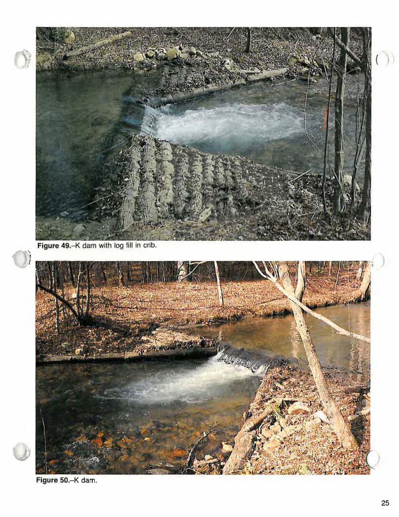
K Dam Purpose - Basically the same as for the wedge dam. Design - Use one log to span the entire stream. Place
braces on the lower side at about 45 degrees to the main log (figures 48 to 50). Add a brace or wing log to the upstream side when leakage around the end is likely to occur, or when unstable banks or streambollom create problems. Use wire and fill material as described in the section on wedge dams. The main log should be at least 16 inches in diameter if available. Dig the log 4- to 6-feet or more into each bank and as deeply into the streambed as possible. Cut a spillway into the log to concentrate low flow to the center of the stream.
Placement - Placement is similar to that described for the wedge dam. However, K dams are best suited for streams less than 15 feet wide.
STRE4M FLOW
~
~
Advantage - Pools tend to be slightly larger and deeper than those created by wedge dams, but the wedge dam is more stable and is easier to maintian. A combination of the two structure types enhances the aesthetics of projects in small streams.
Disadvantage - Installation is more difficult and time consuming than for wedge dams because more extensive excavation is required to seat the main log securely in the bank.
A single, large log must be used to span the stream, increasing the difficulty of hand placement. The probability of washing underneath is greater than for the wedge dam because the main log is usually not seated as deeply into the substrate at the center of the stream.
Cost - One structure per crew day can be installed in streams 10 to 15 feet wide.
Figure 48.-K dam.
) ,
.~ ( I I ,
J
Figure 50.-K dam.
25

AbtJ tm en t loqs ...
· ) 4'..., - - - ---
-1,... --_--1-
II
) '
26
s-/// 5il/
Figure 51.-Fish barrier.
. ~ . 10'---1
~:"..i .... "ltl~.::rl i---, r- ----
NOTE:
1- --, l \ ; ;
I I --, 1---
1.) Bottom SIlls shoUld be anchored 10 bedrock, 11 possible. wllh 1·lnch or bigger steel rods. Old car Of truck axles ara suitable lor thiS purpose.
2.) All log sizes ara approximate. but should be selec:led 10 make dam at leasl 6 reel high, If po$Sibie.
3.) Crib can be filled With rock as constructIOn progresses. or 11 can be Il lIad afierconstruchoo.
4.1 EndS of barrier to extend a ITIIf1IffIUtn 01 1010 15 kter IfftO bank when banks are nor sohd ",,10,
5.) Top 5111 109 (spIlway) shouki be level all !he way &ClOSS. or have a gradual dIP toward the
-", 6.) Upstream sloe oJ slructure should be flied
wilh selected JOCk and gravel 10 a mllXllTlUm slope 01 4: "
7.) Use hemJoclt Of o(her deca~ res.stanl logs. 8.) ~:.. or l..nch retnlorcing sleel should be used
to 118 sil logs. 9.) ~4·, nch lelnforclf'Ig stasi rods should be used
10 anchor he logs to 51111ogs. to.) Use single logS for sills when poSSIble.

): ,
Fish Barrier Purpose - Prevents the upstream migration of undesir
able species offish. In some cases, the objective is to exclude warm water fish from waters managed for trout. In other cases, the objective might be to exclude rainbow and brown trout from brook-trout waters.
Design - The design is basically a log crib filled with rock, incorporating a log apron and log floor to reduce chances of fish jumping the barrier (figures 51 to 57). Overall height of the structure can be 6 feet or less since the log flooring precludes formation of ajump pool. The pool above the structure should be backfilled with coarse rubble and boulders when available.
Placement - In selecting a location, it is essential that stream banks be high enough to handle flood flow without bypassing the structure. Use a cable or attach the structure to bedrock when possible.
J Figure 52.-Bulldozer excavating banks.
Figure 53.- Flooring stream bottom with logs.
))
Figure 54.-Placing sill logs.
Cost - Heavy equipment is essential when building barriers on streams over 20 feet wide. A front-end loader is considerably more cost effective than hand labor when moving large logs and fill material. A crew of eight to ten workers with heavy equipment, logs, gravel, and other mate- ( rials conveniently available can complete a structure on a 20- to 3D-foot wide stream in 3 to 4 days.
Gabions Where proper size rocks are available. gabions can be
used in lieu of logs for structure designs such as deflectors, dams, and bank abutments. The durability of gabions on southern streams has been poor, however, when compared to log structures. Other disadvantages include higher costs and poor aesthetics. In general, when logs are available, use them instead of gabions.
Figure 55.-Fllling crib with rock.
Figure 56.-Completed fish barrier.
Figure 57.-Water spilling through apron onto log floor.
i
) 1
)
27

-)
28
SUGGESTED READING
British Columbia Ministry of Environment. 1980. Stream enhancement guide. Vancouver, B.C. Canada: Ministry of Environment, Fish and Wildlife Branch; 100 p.
Buchanan, Robert A.; Scraton, D.; Anderson, T. 1989. A technical manual for small stream improvement and enhancement in Newfoundland and Labrador. CanadaNewfoundland Inshore Fisheries Development Agreement, P.O. Box 2460, Sin. c., St. John's, NF AIC GES.
Duff, Donald A.; Wydoski, Richard S. Rev. 1988. Indexed bibliography on stream habitat improvement, Ogden, UT: U.S. Department of Agriculture, Forest Service, Intermountain Region, 120 p.
Hassler, Thomas J. 1984. Pacific Northwest stream habitat management workshop. Arcata, CA: Humbolt State University; (available from California Cooperative Fishery Research Unit); 329 p.
Hunt, Robert L. 1988. A compendium of 45 trout stream habitat development evaluations in Wisconsin during 1953-1985. Technical Bulletin No. 162. Madison, WI: Wisconsin Department of Natural Resources; 329 p.
Hunter, Christopher. 1991. Better trout habitat, a guide to stream restoration and management. Washington, DC: Island Press; 320 p.
Miller, Jack G.; Arway, J.; Carline, R. editors. 1986. Fifth trout stream habitat improvement workshop at Lock Haven University; Harrisburg, PA: Pennsylvania Fish Commission; 313 p.
U.S. Department of Agriculture, Forest Service 1982. Proceedings of the trout stream habitat improvement workshop, 1980 November 3-6; Asheville, NC: U.S. Department of Agriculture, Forest Service, Southeastern Forest Experiment Station; 158 p.
White, Ray J.; Brynildson, Oscar M. 1967. Guidelines for management of trout stream habitat in Wisconsin. Tech. Bull. 39. Madison, WI: Department of Natural Resources, Division of Conservation; 64 p.

~gure S8.-Driving rebar with Cobra drill.
Figure S9.-Logs are heavy!
29

-
Figure SO.-Boulders placed for fish cover.