Embed Size (px)
DESCRIPTION
Topics. Slit width and slit separation dependence of diffraction pattern for single and double slits in the Fraunhofer (far-field) regime. Babinet’s principle: Determine the thickness of your hair. Diffraction pattern for circular apertures. - PowerPoint PPT Presentation
Citation preview
Modern Optics LabLab 7: Diffraction and Interference Experiments
Slit width and slit separation dependence of diffraction pattern for single and double slits in the Fraunhofer (far-field) regime.
Babinet’s principle: Determine the thickness of your hair.
Diffraction pattern for circular apertures.
Quantitatively measuring the intensity distribution of the diffraction patterns of single and double slits in the Fraunhofer (far-field) regime and fitting data to theory.
Determination of the ration of slit-width a and slit separation-distance d from the double slit diffraction pattern.
Topics

Modern Optics LabLab 7: Diffraction and Interference Experiments
VII.A Experiments with the Observation Screen
Look at single slit diffraction pattern for different slit widths.
Determine the laser wavelength from the diffraction pattern minima from a single slit.
x
I(x)
L
...3,2,sin :occur when Minima
a
2
2
0
sin
sinsin)(
a
a
II

Modern Optics LabLab 7: Diffraction and Interference Experiments
Babinet’s PrincipleThe diffraction pattern in the far field due to a given screen is the same as the diffraction pattern due to it’s complement.Translation for our experiment:A slit of width a produces the same diffraction pattern as a hair of the same width.
x
I(x)
L
...3,2,sin :occur when Minima
a
2
2
0
sin
sinsin)(
a
a
II
Modern Optics LabLab 7: Diffraction and Interference Experiments
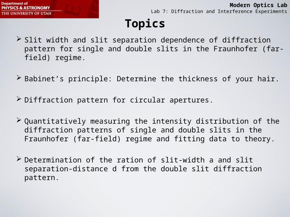
VII.A Determine the Thickness of your Hair
View from the frontTape hair to component holder
Laser beam should hit the hair

Modern Optics LabLab 7: Diffraction and Interference Experiments
VII.A Diffraction pattern of a small circular aperture
View from the front
Use the slide that contains circular apertures of sizes 0.04mm and 0.08mm (those you should use). It also contains a big square and a big round hole with patterns inside.

Modern Optics LabLab 7: Diffraction and Interference Experiments
VII.A Diffraction pattern of a small circular aperture
For circular aperture (a hole) of diameter q the diffraction pattern is an “airy disk”.

Modern Optics LabLab 7: Diffraction and Interference Experiments
Mathematical Description of the Diffraction Pattern of a Circular Aperture in the Far-Field
2
1
0
sin2
sin2
2
a
aJ
IIJ1 = “Order One Bessel Function”
.....,832.3sin2
0sin
2
sin2
0 when Minima
1
aa
aJ
I

Modern Optics LabLab 7: Diffraction and Interference Experiments
Mathematical Description of the Diffraction Pattern of a Circular Aperture in the Far-Field
aperture) ofdiameter (q
22.1832.3
ringdark first for the 832.3sin2
q
q
a
Modern Optics LabLab 7: Diffraction and Interference Experiments
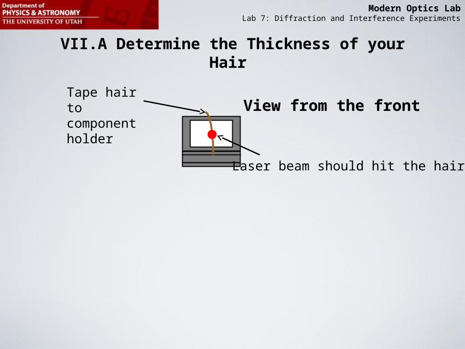
Angle of first minimum (dark circle) (measured from axis that goes through center of the central bright disc):
Small angle approximation ( in radians)

Modern Optics LabLab 7: Diffraction and Interference Experiments
Mathematical Description of the Diffraction Pattern of a Circular Aperture in the Far-Field
69.3238.3
679.2233.2
635.1220.1
0
Maxima Minima
aperture ofdiameter q where, m
sin
:minima and maxima More
m
m
m
m
q

Modern Optics LabLab 7: Diffraction and Interference Experiments
VII.B Experiments with Linear Translator,…….
Observe the diffraction pattern intensities at your setup using the linear translator, photometer, and oscilloscope.
Record patterns using translator, photometer, noise filter, 750 interface, and Data Studio at the front table and email the results to yourself.
Process the measured intensity pattern with Excel and generate a theoretical intensity pattern in Excel.
Compare measured and theoretical pattern in a graph in Excel.

Modern Optics LabLab 7: Diffraction and Interference Experiments
VII.B Example of Processing Single Slit Data in ExcelTime Voltage Time-tc Voltage-Voffset I(t)
0 1.1 -25
1 1.1 -24
2 1.1 -23
3 1.2 -22
….. ….. ……
From Data Studio
Calculate from “Time”-column(Time-tc=0 at peak of pattern)
Calculate from “Voltage”-column(so that Voltage-Voffset goes to zero at the edges of the pattern.
Calculate the theoretical Intensity distribution.
Modern Optics LabLab 7: Diffraction and Interference Experiments
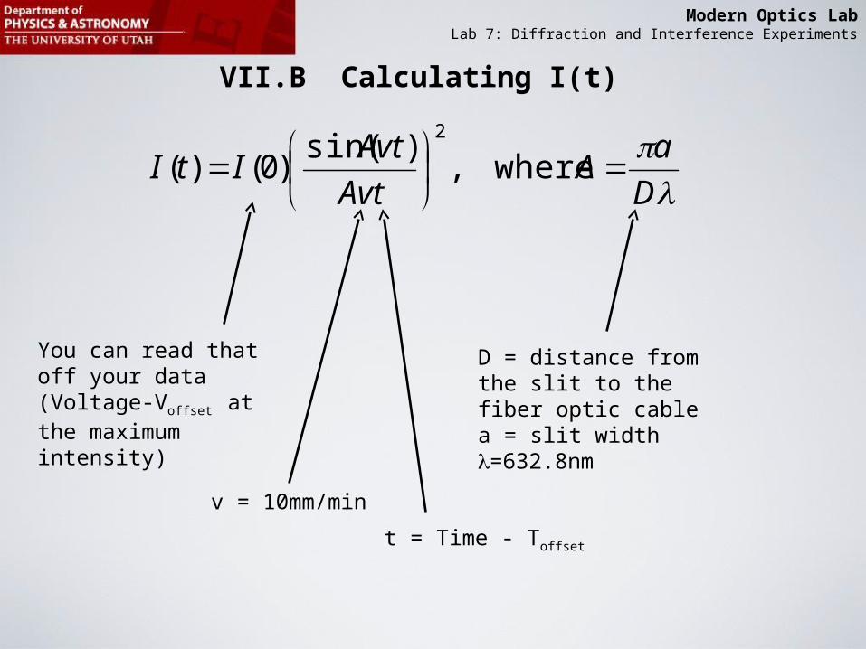
VII.B Calculating I(t)
D
aA
Avt
AvtItI
where,
)sin()0()(
2
You can read that off your data (Voltage-Voffset at the maximum intensity)
D = distance from the slit to the fiber optic cablea = slit width=632.8nm
v = 10mm/min
t = Time - Toffset

Modern Optics LabLab 7: Diffraction and Interference Experiments
VII.B Hints for getting the ratio of slit width a and slit separation d for the double slit from the diffraction pattern.
Double slit maximamdouble=1,2,3
Single slit minimummsingle=1

Modern Optics LabLab 7: Diffraction and Interference Experiments
Double slit maximamdouble=1,2,3
Single slit minimummsingle=1
d
doublemsin :maximaslit Double
a
singlemsin :minimaslit Single