Embed Size (px)
Citation preview
(
t! NASA CR- 54320
,I TOPICAL REPORT VOLUME 3 DESIGN MANUALS
i J BRUSHLESS ROTATING ELECTRICAL GENERATORS| FOR SPACE AUXILIARY POWER sYSTEMS
i,J. N. Ellis ond F.A. Collins
!
i prepared for
i ! NATIONAL AERONAUTICS AND SPACE ADMINISTRATION
CONTRACT NO. NAS 3-2783
,!Li
https://ntrs.nasa.gov/search.jsp?R=19650021093 2018-07-09T04:20:21+00:00Z
NOTICE
This report was prepared as an account of Government sponsored
work. Neither the United States, nor the National Aeronautics
and Space Administration (NASA), nor any person acting onbehalf of NASA:
A.) Makes any warranty or representation, _xpr_sed or
implied, with respect to the accuracy, _teteness,
or usefulness of the information contail,_d in this
report, or that the use of any information, apparatus,
method, or process disclosed in this report may not
infringe privately owned rights; or
B.) Assumes any liabilities with respect to the use of,
or for damages resulting from the use of_a_y infor-
mation, apparatus, method or process _i¢tosed in
thi s report.
As used above, "person acting on behalf of NASA j' includes
any employee or contractor of NASA, or employeel of such con-
tractor, to the extent that such employee or contractor of NASA,
or employee of such contractor prepares, disseminates, or
provides access to, any information pursuant to his employment
or contract with NASA, or his employment with such contractor.
m
E
Requests for cop£es of this reportshould be referred to:
National Aeronautics and Space A_.tionOffice of Scientific and Technical _nformation
Washington, D. C, 20546Attention: AFSS-A '_:=....
|
mB
i
- NASA CR- 54320
TOPICAL REPORT
BRUSHLESS ROTATING ELECTRICAL GENERATORS
FOR SPACE AUXILIARY POWER SYSTEMS
by
J. N. Ellis and F. A. Collins
prepared for
NATIONAL AERONAUTICS AND SPACE ADMINISTRATION
April 26, 1965
Contract No. NAS 3-2783
_d
Technical Management
Howard A. Shumaker
NASA Lewis Research Center
Space Power System Division
Solar and Chemical Power Branch
LEAR SIEGLER, INC.
Power Equipment Division
Cleveland, Ohio

TABLE OF CONTENTS
SE LECTION CRITERIA & MECHANICAL
STUDIES FOR AC GENERATORS
BRIEF DESCRIPTIONS AND SCHEMATICS
Wound Pole, Salient Pole Generator
Wound-Rotor, Non- Salient- PoleGenerator
Rotating Coil Lundell
Single, Inside, Stationary CoilLundell Generator
Two, Inside, Stationary Coil Lundell
Generator (Becky Robinson)
Two, Outside-Coil Imndell
Single, Outside-Coil inndell
Axial Air Gap Lundell
Homopolar Inductor
Permanent- Magnet Generator
How to Start a Design
GENERATOR SELECTION CRITERIA
Discussion
Family Tree Diagram of Generators
Comparison Chart for Brushless AC
Generator Applications (Good-
Better-Best Type Comparison)
VOL. I
SECTION A, VOL.
Page A-I
Page A-8
Page A-I 5
Page A-25
Page A-33
Page A-41
Page A-46
Page A-52
Page A-59
Page A-73
Page A-116
SECTION B, VOL. I
Page B-1
Page B-4
Page B-5
2
Approximate Dimensions for Homopolar
Inductor and Two, Outside CoilLundell AC Generators Page B-6
Weight vs. Output, Wound-Pole, Salient-
Pole, Synchronous Generator Page B-7
Volume vs. Output for Wound-Pole,
Salient-Pole Synchronous Generator Page B-8
Weight vs. Output, Two, Inside,
Stationary Coil I_nndell (Becky
Robinson) with 4 Poles Page B-9
Weight vs. Output, TWo, Inside,
Stationary Coil inndell (Becky
Robinson) with 6 Poles Page B- 10
Weight vs. Output, Two, Inside,
Stationary Coil I_nndell (Becky
Robinson) with 8 Poles Page B-II
Weight vs. Output, Two, Outside
Coil or Single, Outside Coil
Inndell (4 Poles) Page B-12
Weight vs. Output, Two, Outside
Coil or Single, Outside Coil
Lundell (6 Poles) Page B-13
Weight vs. Output, TWo, Outside
Coil or Single, Outside Coil
I_nndell (8 Poles) Page B-13a
Weight vs. Output, Homopolar
Inductor (4 Poles) Page B-14
Weight vs. Output, Homopolar
Inductor (6 Poles) Page B-15
Weight vs. Output, Homopolar
Inductor (8 Poles) Page B-15a
5
Weight vs. Output for Wound,Laminated Stators of AC Electro-
magne tic Generators
Weight vs. Output, Axial Air-GapLundell
Stator Diameter vs. Output forDisk- Type Lundell
Pole Face Losses at No-Load and
Full-Load for Rotors of VariousDiameters
Rotor Diameter vs. Rotor Speedfor Solid Pole Face AlternatorsLimited to 20 Watts/in 2 Pole
Face Losses Based on StatorBore Area
Comparison of No-Load and Full-Load Losses When the Slot Pitch
is Changed
Pole-Face Losses in a Solid Pole
Face Rotor at No-Load as a
Function of Speed
Surface Heat Dissipation from aGenerator Rotor
Discussion of the Performance of
Synchronous Generators WhenUsed as Motors
MECHANICAL AND THERMAL STUDIES
GENERATOR THERMAL ANALYSIS
Table of Contents
Rotor Friction Analysis
Page B-16
Page B-17
Page B-18
Page B-19
Page B-20
Page B-21
Page B-22
Page B-23
Page B-24
VOL. I
SECTION C, VOL.
Page C-0
Page C-A-1
4
GENERATOR ROTOR DYNAMICS
Table of Contents
DISCUSSION OF GAS BEARINGS
Table of Contents
Rolling Contact Bearings
DESIGN FORMULAE FOR BRUSHLESS
A-C GENERATORS
DESIGN CURVES & TABLES
Chord Factors, Table 1
Distribution Factors, Table 2
Wire Table,
Table 3
Wire Table,Table 4
Round Copper
Round Half Size
End-Winding Constant, Curve 1
Pole Face Loss Constants,Curve 2
Pole Face Load Loss Factor,Curve 3
C 1 and Cp, Salient Pole,Curve 4
C1, Cm and Cp Non-Salient Pole,
Curve 4a, 4b
Cx, Curve 5
Damper Loss Constants, Curve 7
Damper Loss Constants, Curve 8
SECTION D, VOL. I
Page D-0
SECTION E, VOL. I
Page E-0
Page E-81
VOL. H
SECTION F, VOL. II
Page F- 1
:Page F-2
Page F-3
Page F- 4
Page F- 5
Page F-6
Page F-7
Page F-8
Page F-7a, b
Page F-9
Page F-10
Page F-11
C m and Cq, Curve 9
Magnetization Curve, Pure Iron,Curve 10
Magnetization Curve, M-43 Silicon
Irons, Curve llA
Magnetization Curve, M36,Curve 11B
Magnetization Curve M-22,Curve llC and llE
Magnetization Curve M- 15,Curve 11D
Magnetization Curve, 1% Max.
Carbon, Curve 12
Magnetization Curve, Cobalt-
Iron, Curve 13
Magnetization Curve For Cast
and Forged Cobalt-iron Alloy,Curve 13b
Magnetization Curve, 4620, 4130,
4140, 6302, Curve 14
Magnetization Curve, 6427, Hy-TUF
410 SS, VASCOJET, Curve 15
Magnetization Curve, 1095, P-6,Curve 16
Magnet Stabilization Point (AT)
Versus Out-of-Stator LeakagePermeance for Alnico V and
Alnico VI, Curve 17
Magnet Stabilization Point (AT)
Versus Out- of- Stator Leakage
Permeance for Alnico VII:I,Curve 18
Page F-12
Page F- 13
Page F-14
Page F- 14
Page F-14
Page F-14
Page F-18
Page F-19
Page F-21
Page F-22
Page F-23
Page F-24
Page F-25
Page F-26
Magnet Stabilization Point (A T)
Versus Out-of- Stator Leakage
Permeance for Alnico VT,
Curve 19
Demagnetization Curves for High
Energy Product Cast Alnicos,
Curve 20
Demagnetization Curve for Cast
Alnico VIII, Curve 21
Demagnetization Curve for Cast
Alnico VIII, Curve 22
Demagnetization Curve for Cast
Alnico V7, Curve 23
Demagnetization Curve for Cast
Alnico VI, Curve 24
Demagnetization Curve for Cast
Alnico V, Curve 25
Iron Losses for Cobalt-Iron Alloy,Curve 13a
Iron Losses for Si-Fe Alloys at
Various Frequencies, Curve llH
Iron Losses for Silicone-Iron Alloys,
at 400 cps, Curve 11F
Iron Losses for Si-Fe Alloys at 60 cps,Curve 11 G
Curve Points of Magnetic Metals
Magnetic Properties of Cr-Ni Steels
MASTER DESIGN MANUAL (SAI.XENT-POLE,
WOUND-POLE, SYNCHRONOUS AC GENERATOR
Input Sheet
Page F-27
Page F-28
Page F-29
Page F-30
Page F-31
Page F-32
Page F-33
Page F-20
Page F-I 7
Page F-15
Page F-16
Page F-34
Page F-36
SECTION G, VOL. II
Page G-01
7
Output Sheet
Design Procedure
DESIGN MANUAL FOR NON-SALIENT,
WOUND-ROTOR, SYNCHRONOUS ACGENERATOR
Page G-03
Page G- 1
SECTION H, VOL. II
Input Sheet
Output Sheet
Design Procedure
DESIGN MANUAL FOR ROTATING- COIL
AC LUNDELL TYPE GENERATORS
Input Sheet
output Sheet
Design Procedure
DESIGN MANUAL FOR SINGLE, INSIDE,
STATIONARY- COIL AC LUNDE LL- TYPE
GENERATOR
Input Sheet
output Sheet
Design Manual
DESIGN MANUAL FOR TWO, INSIDE-
COIL, STATIONARY- COIL AC LUNDE LL-
TYPE GENERATOR (BECKY ROBINSON
PATENT)
Input Sheet
Output Sheet
Design Manual
Page H-01
Page H-02
Page H-I
SECTION J, VOL.
Page J- 01
Page J-03
Page J- I
SECTION K, VOL.
Page K-01
Page K-03
Page K- 1
SECTION L, VOL.
Page L-01
Page L- 04
Page L-I
II
II
II
8
DESIGN MANUAL FOR TWO COIL AND
SINGLE-COIL. OUTSIDE COIL AC
LUNDE LL- TYPE GENERATORS
Input Sheet
Output Sheet
Design Manual For Two-Coil Lundell
Design Manual For One-Coil Lundell
DESIGN MANUAL FOR AXIAL AIR-GAP,
STATIONARY- COI L, SALIENT- POLE,SYNCHRONOUS AC GENERATOR
Discussion
Design Sheet
Design Manual
DESIGN MANUAL FOR HOMOPOLAR
INDUCTOR, AC GENERATOR
Input Sheet
Output Sheet
Design Manual
DESIGN MANUAL FOR PERMANENT
MAGNET, SALIENT-POLE ACGENERATORS
Discussion
Input Sheet
Output Sheet
Design Manual
SECTION M, VOL. II
Page M-01
Page M-03
Page M-1
Page M- 41
SECTION N, VOL. III
Page N- 1
page N-4
Page N- 5
SECTION P, VOL. III
Page P-01
Page P-03
Page P- 1
SECTION R,
Page R- i
Page R-01
Page R-03
Page R- 22
VOL III
EQUIVALENT CIRCUITS
SYMBOL TABLES
SECTION S, VOL. III
SECTION T, VOL. III
GENERATOR THERMAL ANALYSISCOMPUTER PROGRAM (FORTRAN)
SALIENT- POLE WOUND- POLESYNCHRONOUS GENERATOR COMPUTERPROGRAM AND TEST DATA
Computer Input 30 KVA Generator
Computer Output 30 KVA Generator
Test Data 30 KVA Generator
Computer Program (Fortran)
NON- SALIENT- POLE, WOUND- ROTORSYNCHRONOUS GENERATOR COMPUTERPROGRAM AND TEST DATA
Computer Input 120 KVA Generator
Computer Output 120 KVA Generator
Test Data 120 KVA Generator
Computer Program (Fortran)
ROTATING- COIL LUNDE LL, A- CGENERATOR COMPUTER PROGRAMAND TEST DATA
Computer Input 840 Watt Generator
Computer Output 840 Watt Generator
Test Data 840 Watt Generator
10
SECTION CA, VOL. IV
SECTION GA,
Page GA-1
page GA-2
Page GA-5
Page GA-14
VOL. IV
SECTION HA, VOL.
Page HA-I
Page HA-2
Page HA-4
Page HA-29
IV
SECTION JA,
Page JA-I
Page JA-5
Page JA-7
VOL. IV
Computer Program 840 Watt
Generator
INSIDE, SINGLE-COIL, STATIONARY-
COIL LUNDE LL, A- C GENERATOR
COMPUTER PROGRAM AND TEST
DATA
Computer Input
Computer Output
Computer Program
INSIDE, TWO-COIL STATIONARY COIL
LUNDE LL A- C GENERATOR COMPUTER
PROGRAM AND TEST DATA
Computer Input 30 KVA Generator
Computer Output 30 KVA Generator
Test Data 30 KVA Generator
Computer Program
TWO-COIL AND SINGLE-COIL OUTSIDE-
COIL, LUNDE LL, A- C GENERATOR
COMPUTER PROGRAM AND TEST DATA
Computer Input 840 Watt Generator
Computer Output 840 Watt Generator
Test Data 840 Watt Generator
Computer Program
HOMOPOLAR INDUCTOR A-C GENERATOR
COMPUTER PROGRAM AND TEST DATA
Computer Input
ii
Page JA-25
Page KA, VOL.
Page KA-I
Page KA-3
Page KA-22
IV
SECTION LA,
Page LA-3
Page LA-I
Page LA-6
Page LA-37
VOL. IV
SECTION MA, VOL.
Page MA-I
Page MA-3
Page MA-7
Page MA-20
V
SECTION PA, VOL. V
Page PA-01
Computer Output
Test Data
Computer Program
PERMANENT MAGNET A-C GENERATOR
COMPUTER PROGRAM AND TEST DATA
Computer Input
Computer Output
Test Data
Computer Program
DERIVATIONS
Pole Face Losses in Solid-Pole
Gener ato r s
Graphical Flux Analysis
The Maximum _ Ratio for
Rotating Coil LundellA- C Generators
The Maximum # Ratio for
Two, Inside, Stationary-Coil Lundell A-C Generators
The Development of Equations
Describing the Weights of
Electromagnetic Parts for
Three Generator Types
Generator Stator Ampere Load-
ing - A Discussion
Grouping of Fractional Slot
Windings
Distribution Factor
Page PA-03
Page PA-0 5
Page PA-19
SECTION RA, VOL. V
Page RA-1
Page RA-3
Page RA-5
Page RA-22
SECTION SA, VOI,. V
Page SA-I
Page SA-29
Page SA-38
Page SA-40
Page SA-43
Page SA-50
Page SA-53
Page SA- 58
12
Fractional Slot Distribution Factor
Skew Factor
Pitch Factor
Reactances, Per-Unit System
Synchronous Reactance
Reactance of Armature Reaction
Transient Reactance
Subtransient Reactance
Negative Sequence Reactance
Zero Sequence Reactance
Leakage Reactance
Potier Reactance
Time Constants
Resistance
Generator Voltage and Output
Equation s
Cm
%Permeance Calculations
E FFECT OF INCREASING THE AIR GAP
Page SA-60
Page SA- 61
Page SA-64
Page SA-67
Page SA-69
Page SA- 72
Page SA-74
Page SA-78
Page SA- 79
Page SA- 79
Page SA- 80
Page SA-86
Page SA-89
Page SA-9 5
Page SA-96
Page SA- 100
Page SA-103
Page SA- 110
SECTION TA, VOL. V
13
FIGURES
Wound- Pole, Salient- Pole ACGenerator
Wound- Pole., Salient- Pole AC
Generator
Wound- Pole, Rotating-RectifierAC Generator
Wound- Pole Synchronous ACGenerator
Photograph of Wound-Pole
Synchronous Generator
Field Form for Non-Salient Pole
Wound-Pole AC Generator
Rotor Views - NSP AC Generator
Photograph of Rotor & Stator
(NSP Generator)
Photograph of Rotor & Stator
(NSP Generator)
Exploded View of Complete NSPAC Generator
Rotating- Coil I._ndell AC
Generator
Step 1 of Conversion to Outside-
Coil Lundell
Step 2 of Conversion
Figure No.
A-1
A-2
A-3
A-4
A-5
A-8
A-9
A-10
A-11
A-12
A-13
Page No.
A-I
A-4
A-5
A-6
A-7
A-9
A-10
A-11
A-12
A-13
A-14
A-15
A-16
14
Conversion of Rotating-Coil toStationary- Coil Lundell
How to Make a Becky-RobinsonI._ndell
How to Make a HomopolarInductor
Patent Drawing, Rotating CoilLundell
Photo Rotating- Coil /._ndell
Rotor, Rotating-Coil Lundell
Photo, Rotating Coil Ixmdell
Single- Inside, Stationary- Coil
Lundell
Single-Inside, Stationary- Coil
193ndell
Single- Inside, Stationary- Coil
19Jndell
Single- Inside, Stationary- Coil
Lundell Patent Drawing
Photo of Single, Inside, Stationary-
Coil Lunde II
Photo of Single, Inside, Stationary-
Coil Lundell
MG Set
Two-Inside Stationary Coil Iamdell
Two-Inside Stationary Coil Ixmdell
Photo
15
Figure No.
A-14
A-15
A-16
A-17
A-18
A-19
A-20
A-21
A-22
A-23
A-24
A-24a
A-24
A-26
A-27
A-28
Page No.
A-17
A-18
A-19
A-20
A-21
A-22
A-23
A-24
A-26
A-27
A-29
A-30
A-31
A-32
A-33
A-36
Two-Inside Stationary Coil I._mdellPhoto
Two-Inside Stationary Coil IamdellPhoto
Two-inside Stationary Coil Lundell
Flux Circuit
Two-Inside Stationary Coil IxmdellFlux Circuit
Two-Outside Coil Lundell Flux
Circuit Schematics
Two-Outside Coil Lundell Drawing
Two-Outside Coil Lundell Patent
Drawing
Photo Two-Outside Coil Lundell
Single-Coil Outside Coil Lundell
Pole Configuration
Single Coil Outside-Coil I_xmdell
Pole Configuration
Axial Air-Gap hmdell
Axial Air-Gap Lundell Patent
Drawing
Axial Air-Gap Lundell RotorPhoto
Axial Air-Gap Lundell Stator
Photo
Double Axial- Gap Generator
16
Figure No.
A-29
A-30
A-31
A-32
A-33
A-34
A-35
A-36
A-37
A-38
A-39
A-40
A-41
A-42a
A-42c
A-42b
A-42c
Page No.
A-37
A-38
A-39
A-40
A-42
A-43
A-44
A-45
A-48
A-49
A- 50
A-51
A-52
A-55
A-56
A-57
A-58
Figure No. Page No.
Homopolar Inductor
Homopolar Inductor
Homopolar Inductor Rotor
Homopolar Inductor Rotor
Patent Drawing for HomopolarInductor
Patent Drawing for HomopolarInductor
Permanent-Magnet AC Generator
PM Rotor Types
Earliest PM Generator
Patent Drawing for Axial GapPM Generator
PM Hysteresis Loop
PM Hysteresis Loop
Volt Ampere Characteristic
Saturation Curve
Saturation Curve & B r
Air Gap Shear Line
Fdm
Short Circuit Stabilization
Out of Stator Permeance
Shear Line
In-Stator Permeance Shear
Line
A-43
A-44
A-45
A-46
A-47a
A-47b
A-48
A-49
A-50
A-51
A-52
A-53
A-54
A-55
A-56
A-57
A- 58
A-59
A-60
A-61
A-59
A-60
A-64
A-66
A-68
A-69
A-73
A-77
A-78
A-79
A-81
A-84
A-86
A-88
A-89
A-90
A-91
A-92
A-93
A-96
17
Useful Flux
Construction of Load Points On
The PM Generator Hysteresis
Loop
Air Gap Energy Storage
Air Gap Energy Storage
Vector Diagram
Vector Diagrams for AC Generators
Having High Stator WindingResistance
Vector Diagrams for AC Generators
Having Low Stator WindingResistance
Locus of Terminal Voltage
Locus of Terminal Voltage
Volt- Ampere Characteristic
Weight vs. Rating for Salient-Pole
Wound-Pole, Rotating-RectifierAC Generators
Volume vs. Rating for Salient-Pole
Wound-Pole, Rotat2ng-RectifierAC Generators
Weight Breakdown for Two, Inside-
Coil Iamdell Generators (Becky-
Robinson)
Weight Breakflown for a Two-Coil
Outside-Coil, l.audell Generator
18
Figure Nc_
A-62
A-63
A-64
A-65
A-66
A-67
A-68
A-69
A-70
A-71
B-I
B-I
B-2
B-3
B-4
B-5
B-6
B-7
B-8
Page No.
A-98
A-99
A-100
A-101
A-105
A-106
A-107
A-108
A-109
A-110
B-7
B-7
B-8
B-9
B-10
B-II
B-12
B-13
B-14
Figure No. Page No.
Weight Breakdown for a HomopolarInductor AC Generator
Weight vs. Rating for Wound Stators
Weight vs. Stator O.D. for Disk-
Type Dmdell Generators
KVA Output vs. Stator Oo Do for
Disk-Type hmdell Generators
Pole- Face Loss Curves
B-9
B-10
B-11
B-12
B-13
B-14
B-15
B-16
B-17
B-18
B-15
B-16
B-17
B-18
B-19
B-20
B-22
B-23
B-24
B-25
Heat Dissipation From a GeneratorRotor
Induction Motor Speed Torque Curves
Ltmdell Motor Speed Torque Curves
Wound Pole Motor Speed-Torque
Curves
Induced Field Voltage During Start
of Salient, Wound Pole Motor
Alternator Configuration for
Thermal Analysis
Friction Design Charts
Homopolax Inductor Rotor
B-19
B-20
B-21
B-22
B-23
CA-I
CA-2
D-I
B-26
B-28
B-30
B-31
B-34
C-60
C-61
D-8a
19
Outside Coil Lundell Rotor
Becky Robinson Rotor
Rotor Model
Bearing Stiffness Curves
Critical Speeds for Outside-Coil
I_undell
Critical Speeds for Inside-CoilI_nndell
Dynamic Response for HomopolarInductor
Dynamic Response for HomopolarInductor
Dynamic Response for HomopolarInductor
Absolute Viscosity of Various Gases
Self Acting Gas Bearings
Tilting-Pad Bearing Schematic
Load Calculating Charts for
Cylindrical Journal Bearings
Curves for Tilting-Pad Bearings
Self Acting Thrust Bearings
Pressure Rise in Bearing Caps
Friction Vectors in Bearings
Spiral-Groove Thrust Bearings
Figure No.
D-2
D-3
D-4
D-5
D-6
D-7
D-8
D-9
D-10
E-1
E-7
E-8
E-9
E-10
E-11
E-12
E-13
E-14
Page No.
D-8b
D-8c
D-8d
D-8e
D-8f
D-8g
D-8h
D-8i
D-8j
E-11a
E-22a
E-22b
E-22c
E-22d
E-43a
E- 43b
E-43c
E-43d
20
Curvature Effects on Load and
Bearing Stiffness
End- Leakage in Spiral- Grooved
Bearings
Effects of Grooves on Pressure
Profile
Hydrostatic Bearing Stiffness vs.Restrictor Coefficient
Hydrostatic Bearing Stiffness vs.Restrictor Coefficient
Hydrostatic Bearing Flow vs.Restrictor Coefficient
Hydrostatic Bearing Flow vs.Restrictor Coefficient
Hybrid Journal Bearing Load
vs. Compressibility Number
PI, Pole Head Leakage Permeance
P2, Pole Head Side LeakagePermeance
P3 Pole Body End Leakage
Permeance
P4 Pole Body Side Leakage
Permeance
P5 Coil Leakage Permeance
P7 Stator Leakage Permeance
MMF Drops
Diagram of Leakages
21
Figure No.
E-15
E-16
E-17
E-21
E-22
E-23
E-24
E-25
J-4
J-5
J-6
J-8
J-9
J-10
J-ll
J-12
Page No.
E-43e
E-43f
E-43g
E-54a
E-54b
E-54c
E- 54d
E-54e
J-9
d-ll
J-12
J-15
J-16
J-18
J-19
J-20
Pole Dimensions
Rotor & Stator Dimensions
Permeance Path P2
Permeance Path P3, P5
Permeance Path P1, P2, P4
MMF Drops and Leakage Fluxes
Becky Robinson LundeI1 Pole
Types and Dimensions
Rotor Dimensions
Types of Auxiliary Gap and Gap
Dimensions
Rotor Dimensions
Leakage Permeance P3
Leakage Permeance P4 and
MMF Drops
Leakage Permeance P4
Leakage Permeance P4
Coil Leakage Permeance P5
Coil Leakage Permeance P6
Coil Leakage Permeances
P5 and P6
Leakage Permeance P7 fromStator to Rotor
22
Figure No.
K-2
K-3
K-4
K-5
K-6
K-7
L-4
L-5
L-6
L-7
L-8
L-9
L-10
L-11
L-12
L-13
Page No.
K-7
K-9
K-11
K-12
K-13
K-14
L-11
L-13
L-17
L-18
L-19
I.,-20
L-22
L-23
I.,-24
L-25
Figure No. Page No.
Outside-Coil Lundell Stator and
Rotor Dimensions
Leakage Permeance P1
Leakage Permeance P2
Leakage Permeance P3
Leakage Permeance P4
MMF Drops and Leakage Paths
in Outside-Coil hmdell
Three Possible Locations and
Permeances P5, P7
Leakage Flux 07 From Stator
to Rotor
Leakage Permeances for l-coil
Outside- Coil Lundell
Stator Leakage Flux 07
MMF Drops in outside-Coil
Landell and Leakage Flux 07
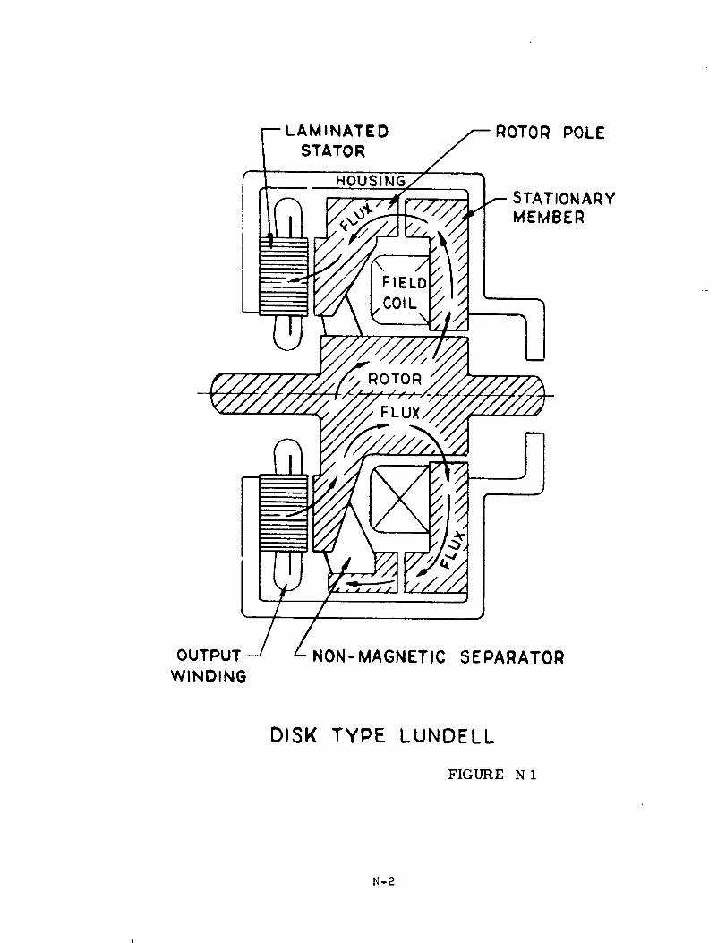
Disk- Type Lundell Generator
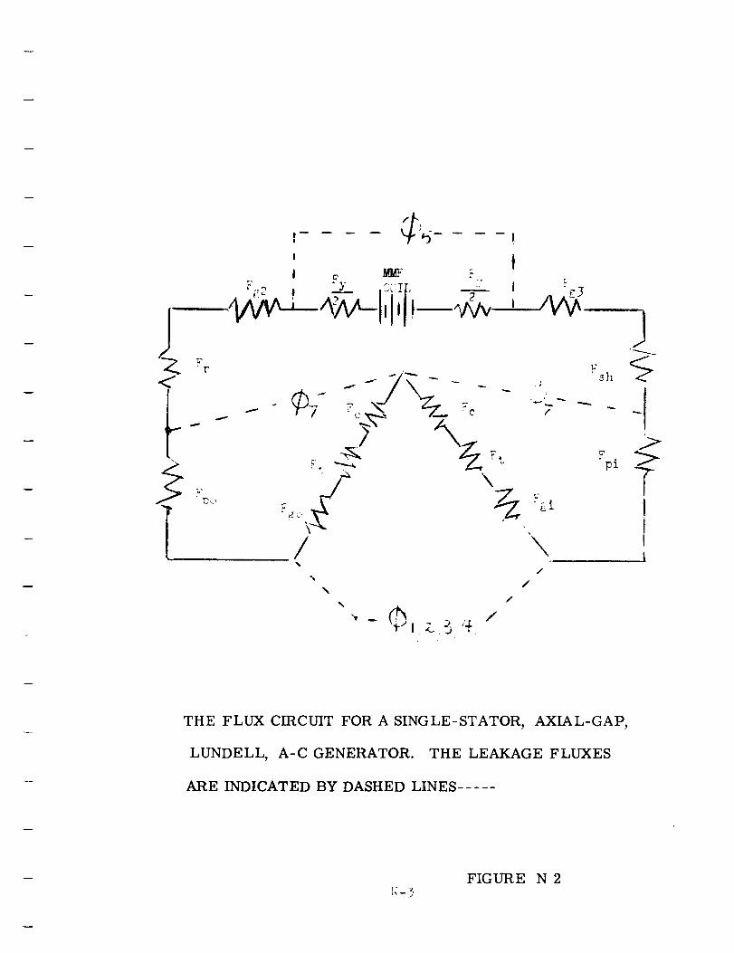
Flux Circuit for Disk-TypeI_nndell
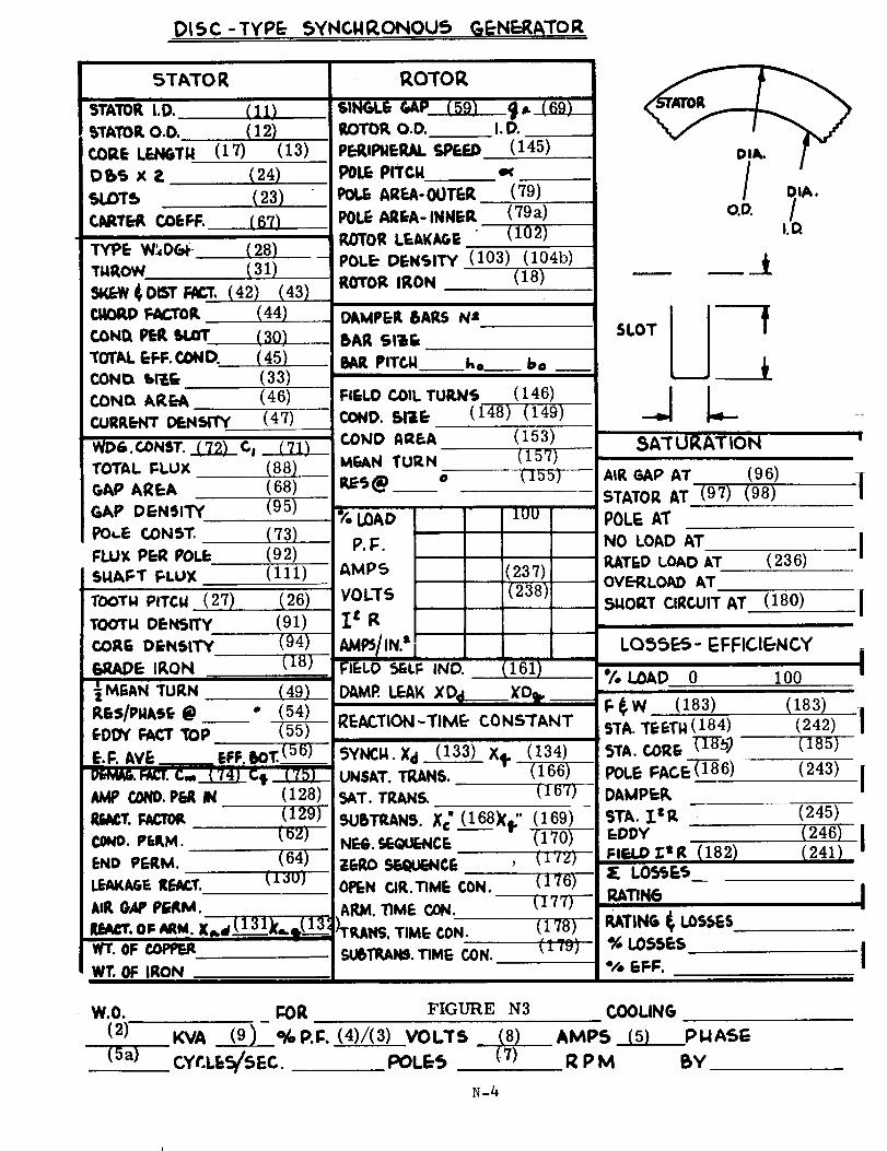
Design Sheet for Disk-Typehmdell
Pole Dimensions
Pole Dimensions
Rotor Leakage Permeances
Rotor Leakage Permeance P4
25
M-3
M-4
M-5
M-6
M-7
M-8
M-9
M-10
M-14
M-15
M-16
N-I
N-2
N-3
N-4a
N-4b
N-5
N-6
M-9
M-13
M-14
M-15
M-16
M-17
M-18
M-21
M-52
M-53
M-54
N-2
N-3
N-4
N-26
N-26
N-27
N-29
Homopolar Inductor HousingType 1 Item (78)
Types 2 and 3
Homopolar Inductor ShaftDimensions Item (78a)
PM Generator
Rotor Leakage Permeances
Rotor Leakage Permeance P1
Curve for P1
Rotor Leakage Permeance Ps
Rotor Leakage Permeance Pf
Curve for Leakage Permeance P2
Rotor Leakage Permeance Psl
Rotor Pole Tip Leakage
Rotor Leakage Permeance Ps2
Rotor Leakage Permeance P3
Curve for P3
Magneti Comparisons
Magnet Comparisons
Equivalent- Circuit Representation
for Synchronous AC Generator
Carrying a Balanced Load
Figure No.
R-I
R-2
R-3
R-5
R-6
R-7
R-8
R-9
R-10
R-I1
R-12
R-13
R-14
R-15
Page No.
P-10
R-2
R-4
R-5
R-7
R-8
R-9
R-10
R-I1
R-13
R-14
R-15
R-16
R-20
R-21
S-33
24

Figure No. Page No.
Equivalent- Circuit Representation
for Synchronous AC Generator
Carrying a Balanced Load S-35
Equivalent Circuit for Synchronous
AC Generator Carrying an
Unbalanced Load S-73
Equivalent Circuit for Synchronous
AC Generator Carrying anUnbalanced Load S-74
25
TAB LE S
List of Cobalt Steels
Table of PM Steel Characteristics
Table of PM Steel Characteristics
Table of PM Steel Composition
Family Tree of Brushless AC
Generators
Comparison Chart for BrushlessAC Generators
Approx. Dimensions for Homopolar
Inductors and for Outside-Coil
Lundell AC Generators
Gas Bearings
Operating Requirements of Gas
Bearing Types
Gas Lubricated Journal Bearing
Family Tree
Gas Lubricated Thrust Bearing
Family Tree
Required Design Information
Bearing Parameter for Maximum
Load Capacity
Bearing Tolerance Ranges
Effects of Grooves in Gas Bearings
Page A-Ill
Page A-II3
Page A-II4
Page A-II5
Page B-4
Page B-4
Page B-6
Page E-7
Page E-8
Page E-9
Page E- 10
Page E-II
Page E-41
Page E-42
Page E- 43
26
Alloy Classes Useful as Base Materials
for Shaft and/or Bearings
Material Combinations that Have Been
Used for Large Bearings
Bearing (Rolling Element) LifeDispersion Curve
Speed and Size of Light and Extra LightSuperprecision Ball Bearings
Page E-76
Page E-77
Page E-82
Page E-84
Inner-Race RPM for Oil Jet or Oil-Mist
I_nbrication Extra Light Series BallBearings
Limiting Speeds for Grease I.nbricatedBall Bearings
Temperature Limitation of Ball Bearings
Page E-85
Page E-86
Page E-87
27
!
!
i
!
!
!
Section
Section B
Section CA or Section C
Section
Section E:-.
Section F
Section GA or Section G
!
!
Section HA or Section H
Section JA or Section J
!
I
i
I
i
I
i
!
|
Section KA or Section
Section Lk or Section
Section MA or Section M_:
Section N
Section PA or Section Ia
Section RA or Section R
Section SA or Section S ....
Section TA or Section T :

|
|
|
|
|
|
|
|
|
im
|
|
_w
|
|
!
!
I
I
!
i
I
I
i
!
I
I
I
DESIGN MANUAL FOR AXIAL AIR-GAP,
STATIONARY- COIL, SALIENT- POLE,
SYNCHRONOUS A-C GENERATOR
i
I
I
i
L|SECTION N _ _
I
|
!
!
f
|
!
!
E
!
1
|
!
!
!
|
!
THE AXIAL AIR-GAP, LUNDELL-TYPE, A-C GENERATOR
The design manual presented here in section N, is a hand-
calculation manual arranged for computer programming.
To use this manual we suggest following the sequence
indicated by the arrangement of the design sheet, Fig. N 3
The numbers in brackets on the design sheet give the item
number of that particular calculation. The items in the
design manual are given in the sequence indicated by their
number.
--LAMINATEDSTATOR
,
! •
12
HOUSING
/FIELD
COlL
ROTOR POLE
r STATIONARYb, MEMBER
,/r/,<..,_///"
# .
//
Z_/
I
I, I
L-_
Li
i • .
OUTPUT J
WINDING
Z. NON- MAGNETIC SEPARATOR
DISK TYPE LUNDELL
FIGURE N 1
I_-2
' tI _, _ =
"F
Yt
• t7 _,
!%
f
"\/
J
/
J%f..>
11L
THE FLUX CIRCUIT FOR A SINGLE-STATOR, AXIAL-GAP,
LUNDELL, A-C GENERATOR. THE LEAKAGE FLUXES
ARE INDICATED BY DASHED LINES .....
FIGURE N 2
DL_C-TYP_ _YNGNRONOU_ CaE.NERATOR
5TATOR
5TATOR I.D. (11)
S'TATOe.O.0. (12)CORE LENGTH (17) (13)
Dbs x z (24)SLOTS (23)CNIT£4 I, COEFF. (67)
TYPE W_,O(._- (28)
TI.IROW ( 31)
sv.ew¢OmTr.._r. (42) (43)r._o_ _0_. (44)COND._ u.m" (30)TOTALEFF.CO_D. (45)CON O. 'b_@ ( 33)
COND. AREA (46)
CURRENT DENsrTY (47)
WD&.GONST..__7.2)_ C, (71)
TOTAL FLUX (88)AREA (68)
G,&P O EN=31'TY (95)
PO,.E CONST. (73)FLUX PER POLE (9 2)
St4AFT FLUX (111)
TOOTI4 PITCI.I (27) (26)
TOO'rl.l DEI',I_ITY (91)
CORG DENSITY (94)
6_l?Jld_E Ill, ON (18)
MEAN TURN (49)
RE$/PN&SE @ ° (54)
eDDY _T ToP (55)
E.l::. AVE__ EFF.!,O!:.(56..__)__)
Dr,MAC,.FACT.C,,,, (74) C.,I,AMP COND.eEJ( IN (128)
Rr_cT. FACTOR. (129)
co_o. er=e,M. (_v.)
END PERM. (64)
ROTOR
SINGLE GAP (59) _$ (69)
ROTOR O.O. I.D.
PEPJPMERAL SPEED (145)
POLEPITCH =xAREA-0UTER (79)
POLE ARr¢A- INNER (79a)
P_I'OR L_=AK/_ (102)
POLE" DENSITY (103) (104b)
ROTOR IRON (18)
DIEMPER BARS N=
BAR SlOE
PITCI,I ko__ bo
FIELD COIL TUILN_ (146)
COND. Sine (148) (149)
COMO AREA (153)
Mr=_N TURN (157)
% LOAD
P.l:.
AMP_
VOLT._
Z= R
AMI_/IN." lFIELD 5ELF IND.
" 1UU
(237)
(238)
i
:161)
DAMP. LEAK XDc____X'D_,__
REACTION-TIME- CONSTANT
_YNC..x_ (133)xe (134)UN$&T. TRANS. (166)
SAT. roANS (1_)
SUBTR&N$. X_ (168X_' (169)
N_. SC-eUC-NCE (170)ZeRO _CE , ( J _z)
o.LI.l:l
__ __A
SLOT
5A'I'URAT|ON
AIR C._P AT (9 6)
STATOR AT (97) (98)
POLE AT
NO LOAD AT
RATED LOAD ATOVERLOAD AT
.T_IORT CIRCUIT AT
(236)
(180)
LO,_SE._- EFFICIE-NCY
_/_ LOAD 0 100
F.$W (183)
9TA. TEETI.I (184)
ETA.COR_TI__)POLEr:ACe:'-_6)DAMPEI_
STA. _.=Rr-DDY
FIF.J.DZ:tR (182)
|
I
(183)(242) [(185)
(243) I(245)
(246)' ' I(241)
AIR GAP PERM." --- ARJ_. TIME CON. _7T)-- .e._,,r_=.
I o, C0N (' I RAT|NG _' LOSSES
I WT. OF IRON I II _ ,
W.O. F-OR FIGURE N3 COOLING
(2) KVA (9)- 9GP.I::. (4)/(3) VOLTS (8) AMP$ (5) PlJAS_
(5a) CYr.LES/$EC. POLES (7) R P M BY
N-4
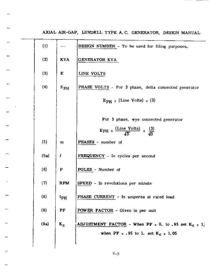
AXIAL AIR-GAP, LUNDELL TYPE A.C. GENERATOR, DESIGN MANUAL
(1)
(2)
(3)
(4)
(5)
(5a)
(6)
(7)
(8)
(9)
(ga)
KVA
E
EpH
m
P
RPM
IpH
PF
K C
DESIGN NUMBER - To be used for filing purposes.
GENERATOR KVA
LINE VOLTS
PHASE VOLTS For 3 phase, delta connected generator
EpH = (Line Volts) : (3)
For 3 phase, wye connected generator
Ep H = (Line Volts) = (3__)4r 45-
PHASES - number of
FREQUENCY - In cycles per second
POLES - Number of
SPEED - In revolutions per minute
PHASE CURRENT - In amperes at rated load
POWER FACTOR - Given in per unit
ADJUSTMENT FACTOR - When PF = 0. to .95 set K c = I;
when PF = .95 to I. set K c = 1.05
N-5
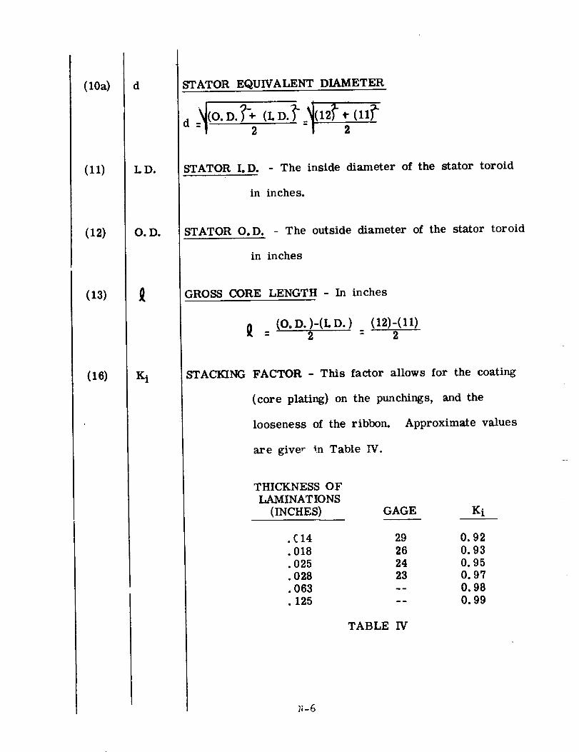
(10a)
(11)
(12)
(13)
(16)
d
I.D.
Oo Do
STATOR EQUIVALENT DIAMETER
d _._(O. D. );_'÷ (L D. _" .I(12_" • (11_"- 2 2
STATOR I.D. - The inside diameter of the stator toroid
in inches.
STATOR O.D. - The outside diameter of the stator toroid
in inches
GROSS CORE LENGTH - In inches
(O. D. )-(L D. ) (12)-(11)" 2 - 2
STACKING FACTOR - This factor allows for the coating
(core plating) on the punchings, and the
looseness of the ribbon. Approximate values
are giver in Table IV.
THICKNESS OF
LMVIINATIONS
(INCHES)
.£14
.018
• 025
• 028
• 063
• 125
GAGE Ki
29 0.92
26 0.93
24 0.9523 0.97
-- 0.98
-- 0.99
TABLE IV
N-6
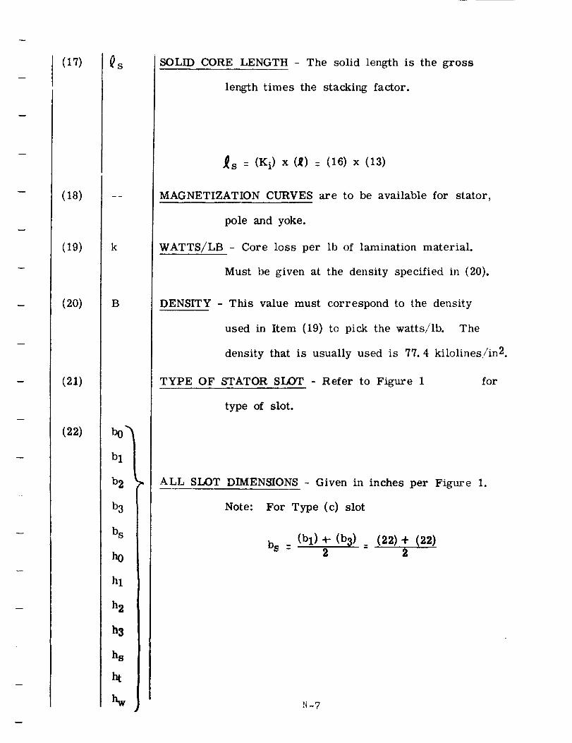
(17)
(18)
(19)
(20)
(21)
(22)
QS
k
B
bl
b2
b3
bs
h0
hl
h 2
h3
ha
ht
SOLID CORE LENGTH - The solid length is the gross
length times the stacking factor.
_s = (Ki) x (,_) = (16) x (13)
MAGNETIZATION CURVES are to be available for stator,
pole and yoke.
WATTS/LB - Core loss per lb of lamination material.
Must be given at the density specified in (20).
DENSITY - This value must correspond to the density
used in Item (19) to pick the watts/lb. The
density that is usually used is 77. 4 kilolines/in2.
TYPE OF STATOR SLOT - Refer to Figure 1 for
type of slot.
ALL SLOT DIMENSIONS - Given in inches per Figm'e 1.
Note: For Type (c) slot
b S _-(b 1) -I- (b 3)
2 2_ (22) ÷ (22)
N-?
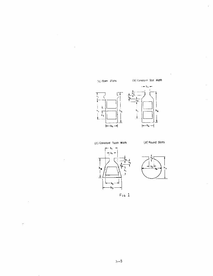
C,C_)Open Slots
!,LU
---bs --_
(b) Constant Slot _/idth
-.- bo _
j[___ 1
_b.-t
(C) Constant Tooth Width
F_G i
(d) Round Slots
_-8
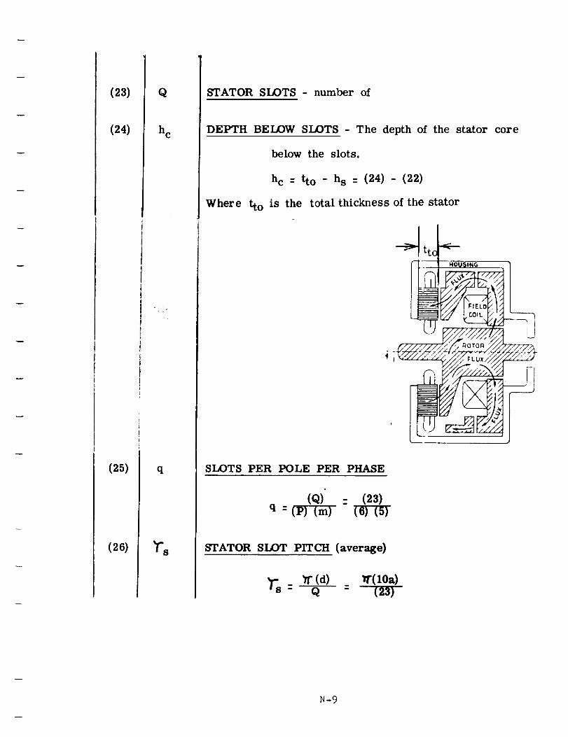
(23)
(24)
(25)
(26)
Q
h C
q
_'S
STATOR SLOTS - number of
DEPTH BELOW SLOTS - The depth of the stator core
below the slots.
hc : tto - hs : (24) - (22)
Where tto is the totM thickness of the stator
-4
SLOTS PER POLE PER PHASE
(Q) : (23)q = (P) (m) (6)(5)
STATOR SLOT PITCH (average)
_s _" (d) W'(10a)- Q - (_3)
N-9
(27)
(28)
(29)
STATOR SLOT PITCH - I/3 distance up from narrowest
section of tooth.
'Is 1/3 : Ts : (26)
TYPE OF WINDING - Record whether the connection is
wye or delta
TYPE OF COIL - Record whether random wound or formed
coils are used.
N-IO
(30)
(31)
(31a)
(32)
(33)
C
n s
Y
CONDUCTORS PER SLOT - The actual number of con-
ductors per slot. For random wound coils use
a space factor of 75% to 80%. Where space
factor is the percent of the total slot area
that is available for insulated conductors after
all other insulation areas have been subtracted
out.
THROW - Number of slots spanned. For example, with
a coil side in slot 1 and the other coil side
in slot 10, the throw is 9.
PERCENT OF POLE PITCH SPANNED - Ratio of the number
of slots spanned to the number of slots in a
pole pitch
(y) (31)= (m)(q) :
PARALLEL PATHS, no. of - Number of parallel circuits
per phase
STRAND DIA OR WIDTH - In inches. For round wire,
use strand diameter. For rectangular wire,
use strand width.
N-f1
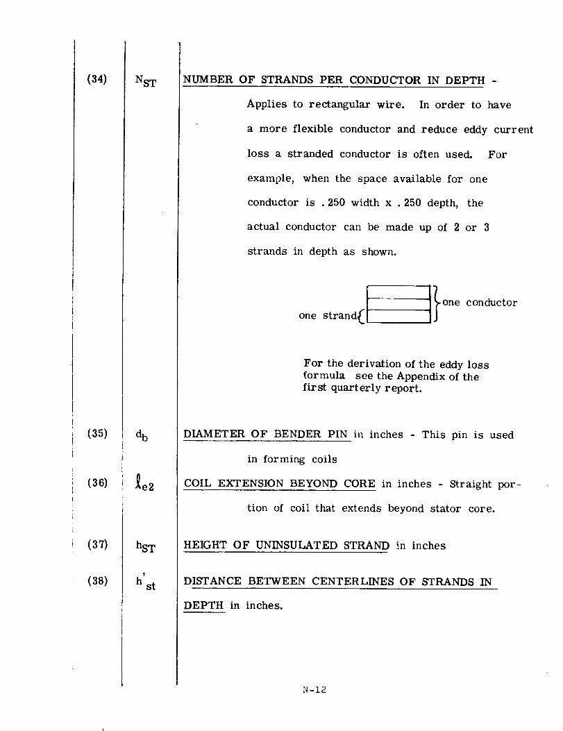
(34)
(35)
(36)
(37)
(38)
NST
d b
_e2
hST
!
hst
NUMBER OF STRANDS PER CONDUCTOR IN DEPTH -
Applies to rectangular wire. In order to have
a more flexible conductor and reduce eddy current
loss a stranded conductor is often used. For
example, when the space available for one
conductor is . 250 width x . 250 depth, the
actual conductor can be made up of 2 or 3
strands in depth as shown.
onestr n It}one conductor
For the derivation of the eddy lossformula see the Appendix of the
first quarterly report.
DIAMETER OF BENDER PIN in inches - This pin is used
in forming coils
COIL EXTENSION BEYOND CORE in inches - Straight por-
tion of coil that extends beyond stator core.
HEIGHT OF UNINSULATED STRAND in inches
DISTANCE BETWEEN CENTERLINES OF STRANDS IN
DEPTH in inches.
N -12
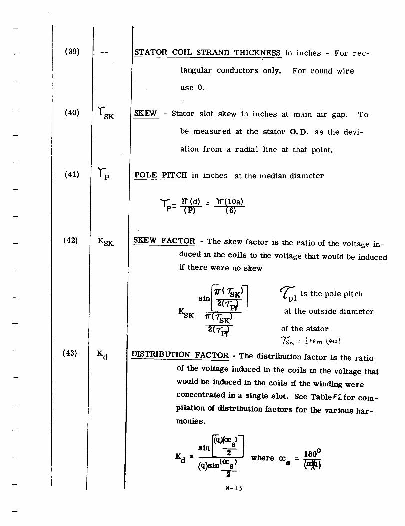
(39)
(40)
(41)
(42)
(43)
KSK
K d
STATOR COIL STRAND THICKNESS in inches - For rec-
tangular conductors only. For round wire
use 0.
SKEW Stator slot skew in inches at main air gap. To
be measured at the stator O. D, as the devi-
ation from a radial line at that point.
POLE PITCH in inches at the median diameter
- (10a)(6)
SKEW FACTOR - The skew factor is the ratio of the voltage in-
duced in the coils to the voltage that would be induced
if there were no skew
/KSK "/T('TsK) "
2(Tv
_pliS the pole pitch
at the outside diameter
of the stator
DISTRIBUTION FACTOR - The distribution factor is the ratio
of the voltage induced in the coils to the voltage that
would be induced in the coils if the winding were
concentrated in a single slot. See Table FZ for com-
pilation of distribution factors for the various har-
monies.
Kd = (q)sin(OCs) where ccs =
T
N-13
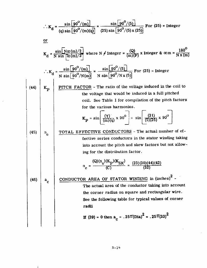
(44)
(45)
(46)
or
Kd =
• .K d =
zp
n e
a C
(25) xFor (25) = Integer
+ I-N+ImV+ 0+)N sin _c(m)/2J where N / Integer = _ x Integer & ccm =
180 °
N x (m)
For (25) = Integer
PITCH FACTOR - The ratio of the voltage induced in the coil to
the voltage that would be induced in a full pitched
coil. See Table 1 for compilation of the pitch factors
for the various harmonics.
Kp= sin__q_ x 90_= sin__x 90°_
TOTAL EFFECTIVE CONDUCTORS - The actual number of ef-
fective series conductors in the stator winding taking
into account the pitch and skew factors but not allow-
ing for the distribution factor.
(Q)(ns)(Kp)(KsK) _ (23)(30)(44)(42)
ne = (C) (32)
CONDUCTOR AREA OF STATOR WINDING in- -(inches)2 -
The actual area of the conductor taking into account
the corner radius on square and rectangular wire.
See the following table for typical values of corner
radii
If (39) = 0 then ac = .2571"(Dta)2 =. 25/I"(33)2
N-14
w
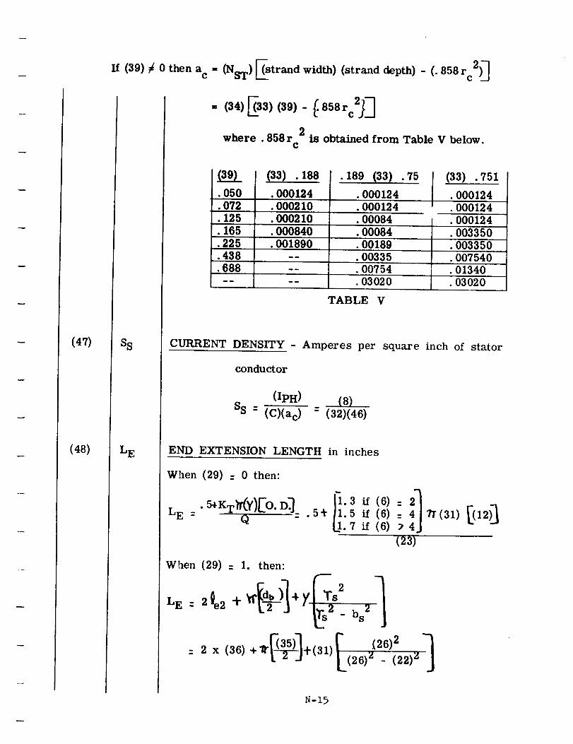
(47)
(48)
If (39) _ 0 then a c = (NsT) Estrand width) (strand depth) - (. 858 rc2)_
SS
L E
= (34)_33)(39)- _.858rc2_
2where .858r
Cis obtained from Table V below.
(39)• 050
(33) . 188
.000124
• 189 (33) .75
.000124
• 072 •000210 •000124
• 000210 .00084
•000840 •00084
• 125
• 165
.225
• 438
• 688
I (33) .751• 000124
• 000124
• 000124
• 003350
.001890 .00189 .003350
-- •00335 •007540
-- .00754 .01340• 03020 • 03020
TABLE V
CURRENT DENSITY - Amperes per square inch of stator
conductor
(IpH) (8)
SS- (C)(a c) - (32)(46)
END EXTENSION LENGTH in inches
When (29) : 0 then:
LE . 5_KT_Y)_O. D_Q • 5_ 1.5 if (6) _(31) 12
.7 if (6)
(23)
When (29) = 1. then:
LE: 2_e2 "t" _.2 J i,rS,
_-_] _ "(26)2= 2 x (36)+_ +(31) (26) 2 _ (22) z
N-15
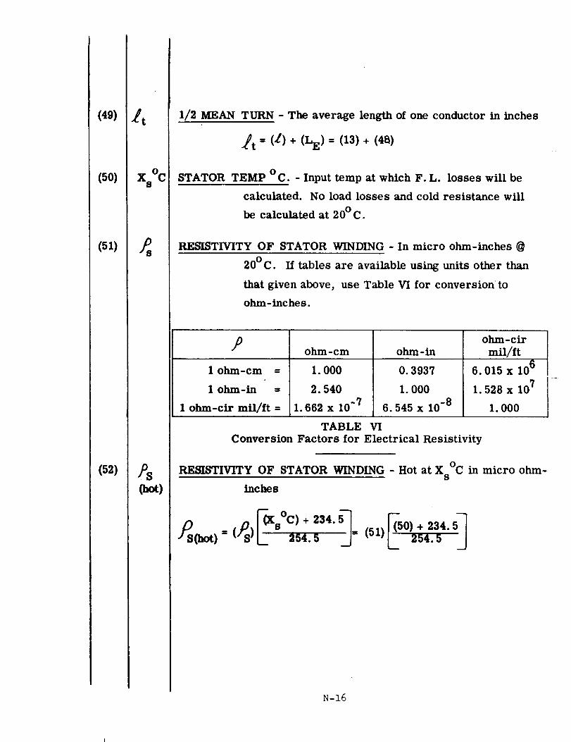
(49)
(50)
(51)
(52)
,4. t
V v I'q
A_ %J
v
JS
,/.q
(hot)
1/2 MEAN TURN - The average length of one conductor in inches
_t = (L) + (LE) = (13) + (4t_)
STATOR TEMP °C. - Input temp at which F.L. losses will be
calculated. No load losses and cold resistance will
be calculated at 20°C.
RESISTIVITY OF STATOR WINDING - In micro ohm-inches @
20°C. If tables are available using units other than
that given above, use Table VI for conversion to
ohm-inches.
D ohm-cir
ohm-cm ohm-in mil/ft
1 ohm-cm =
1 ohm-in =
1 ohm-cir mfl/ft =
1. 000
2. 540
1. 662 x 10 -7
0.3937
1.000
6.545 x 10 -8
6.015 x 10⁶
1.528 x 10⁷
1.000
TABLE VI
Conversion Factors for Electrical Resistivity
RESISTIVITY OF STATOR WINDING - Hot at X °C in micro ohm-s
inches
)_S(h=)= (_S)L' 254.5 = (si)L 2s_.s
N-16
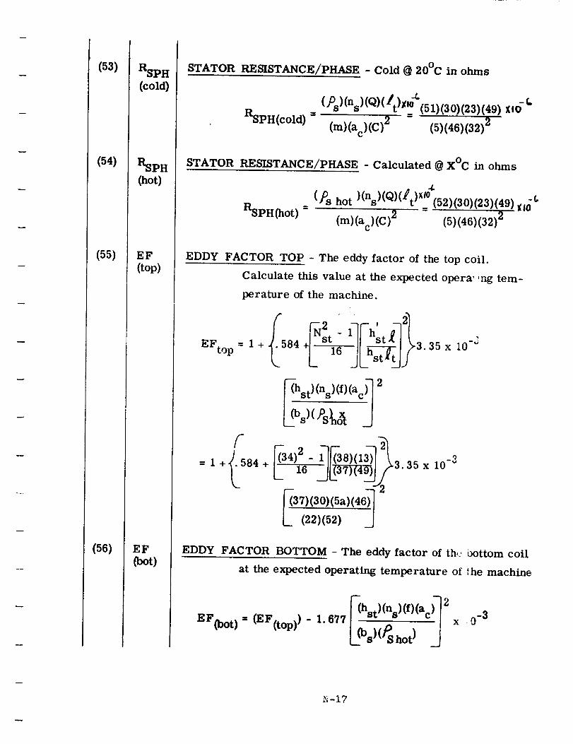
(53)
(54)
(55)
(56)
RSPH
(cold)
RSPH
(hot)
EF
(top)
EF
(boo
STATOR RESISTANCE/PHASE - Cold @ 20°C in ohms
RsPH(cold ) =()Ds)(ns)(Q)(_/t)X,o-_(51)(30)(23)(49) Xl0-f=
(m)(ac)(C) 2 (5)(46)(32) 2
STATOR RESISTANCE/PHASE - Calculated @ X°C in ohms
RsPH(hot) =()0s hot )(ns)(Q)(_t)x_4"(52)(30)(23)(49) -c
= _lO
(m)(ac)(C)2 (5)(46)(32) 2
EDDY FACTOR TOP - The eddy factor of the top coil.
Calculate this value at the expected opera' ,ng tem-
perature of the machine.
EFto p
f= 1 +,). 584
= 1+ 84
hst) (ns) (f)(ac_
+E--f_-2_)(_922f_. _ x,0-3__(37) (30)(5a) (46_)_
EDDY FACTOR BOTTOM - The eddy factor of the., t>ottom coil
at the expected operating temperature of the machine
677 _(hst) (ns) (f) (ac_)]
EF(b°t) ffi(EF(t°P))-l" L_ j
-17
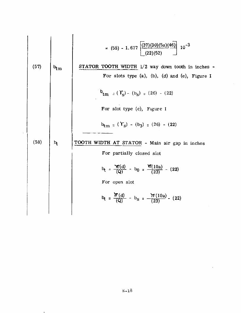
(57)
(58)
btm
_37)(30)(5a)(4_ 1--(55)-i.677 L(---_22)(-_2) -_j io -3
STATOR TOOTH WIDTH 1/2 way down tooth in inches -
For slots type (a), (b), (d) and (e), Figure I
-btm : (_s)- (bs) : (26) (22)
For slot type (c), Figure I
btm : ('f's) - (b3) : (26) - (22)
TOOTH WIDTH AT STATOR - Main air gap in inches
For partially closed slot
"Tr(d) '#'(lOa) _ (22)bt = _ - b0 = (23)
For open slot
_P(d) bs :bt:_-_(lOa)(23) - (22)
N-18
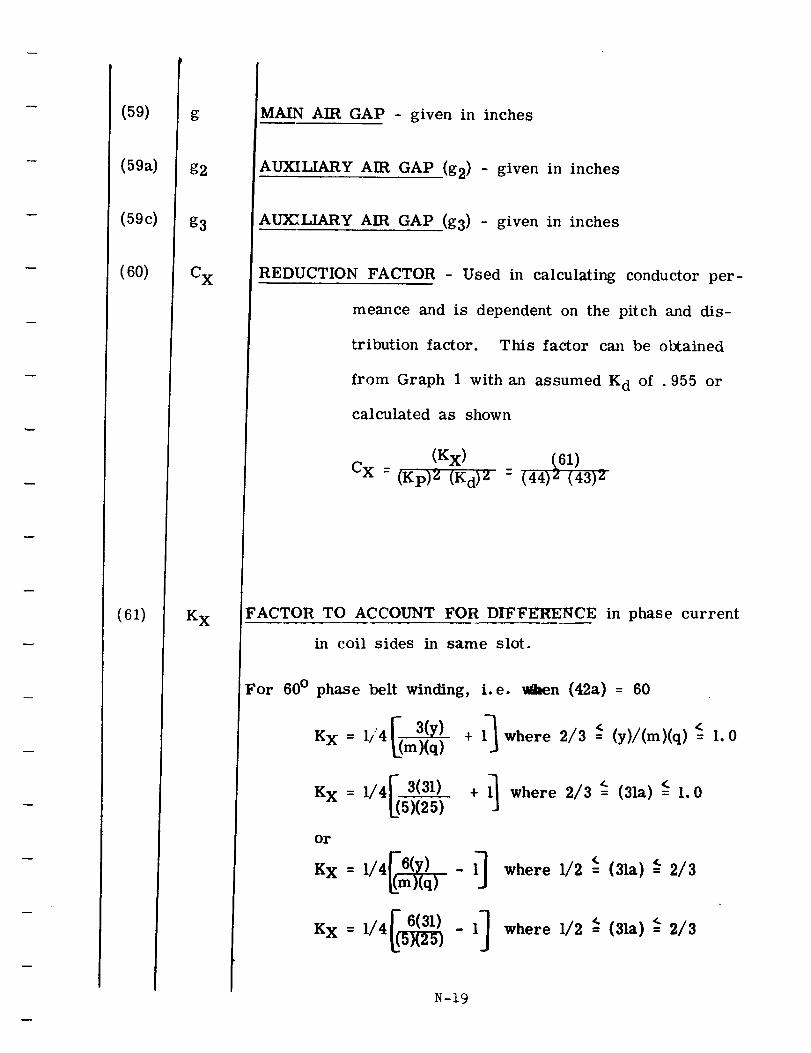
(59)
(59a)
(59c)
(60)
(61)
g
g2
g3
C x
K x
MAIN AIR GAP - given in inches
AUXILIARY AIR GAP (g2) - given in inches
AUXILIARY AIR GA1 a .(g3) - given in inches
REDUCTION FACTOR - Used in calculating conductor per-
meance and is dependent on the pitch and dis-
tribution factor. This factor can be obtained
from Graph 1 with an assumed K d of .955 or
calculated as shown
(Kx) (61)
CX = (Kp)2 (Kd)2 : (44)2 (43)2
TO ACCOUNT FOR DIFFERENCE in phase current
in coil sides in same slot.
V 3(y)K X - 1/4_m)(q)
K x = 1/4[ 3(31)
For 60 ° phase beR winding, i.e. _en (42a) = 60
+ l_ where 2/3 =<(y)/(m)(q) ':= 1.0
I_ where 2/3 _ <+ = (31a)= 1.0J
or
K x = 1/4_(m6_)q)-1-J
KX = 1/4I( _ - 1]
where 1/2 < <= (3 a) = 2/3
where 1/2 _ (31a) _ 2/3
N-19
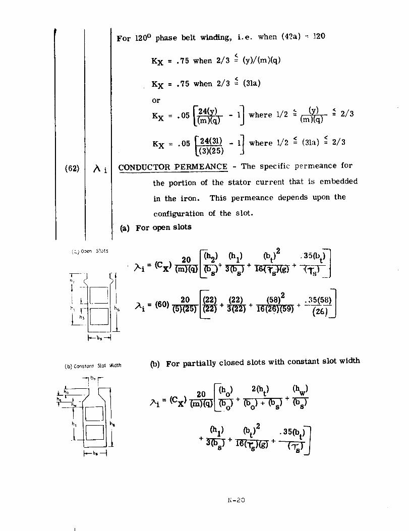
(62)
For 120° phase beR winding, i.e. when (42a) - 120
K X = .75 when 2/3 =< (y)/(m)(q)
K X = .75 when 2/3 (31a)
or
K x = .05 [(m)(q) - where =
= .05 [24(31) _ ll where I/2 -<-(31:t)=< 2/3KX[(3)(25) ]
CONDUCTOR PERMEANCE - The specific permeance for
the portion of the stator current that is embedded
in the iron. This permeance depends upon the
configuration of the slot.
(a) For open slots
_qj_'Open SIo_s
T--] _--n_
k-b,-4
20 __ (hl)(bt)2 .35(bt) _
/_i (6o) 2o= (5)(25) (22) (58)2+ _ + 16(26)(59) +
(b)Cons$ont SlotWiclth
_bo F-
_b,--t
(b) For partially closed slots with constant slot width
20 _ho) 2(ht) (hw)
+ (bo)+ (bs)+ W_-
(h 1) (bt)2 .35(bt) _
N-20
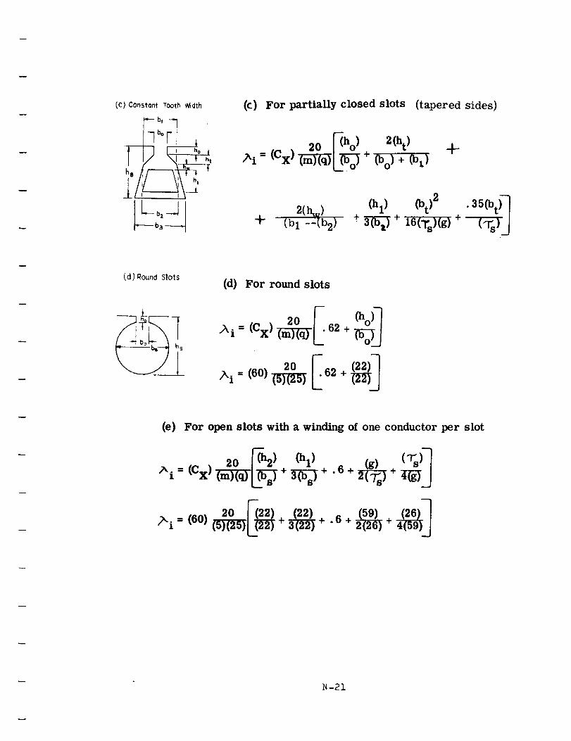
(C) Constont Tooth Width
"--bt -_
h:: l
(c) For partially closed slots (tapered sides)
20 r(ho ) 2(ht)
/_i- (Cx)_L_-O_ + c%)+(bt)÷
2(I_) (hl) (bt)2 "35(bt)_
_" (bI -:(b2) + 3-_ + 16(Ts)(g ) + (:Vs)J
(d) Round Slots(d) For round slots
(e) For open slots with a winding of one conductor per slot
/xi = (Cx) +_+ .6+ +
20 1"(22) (22) (59) (26)-'_
>i = (60)(w_L__ + _ +. 6 +_ +
N-21
(63)
(64)
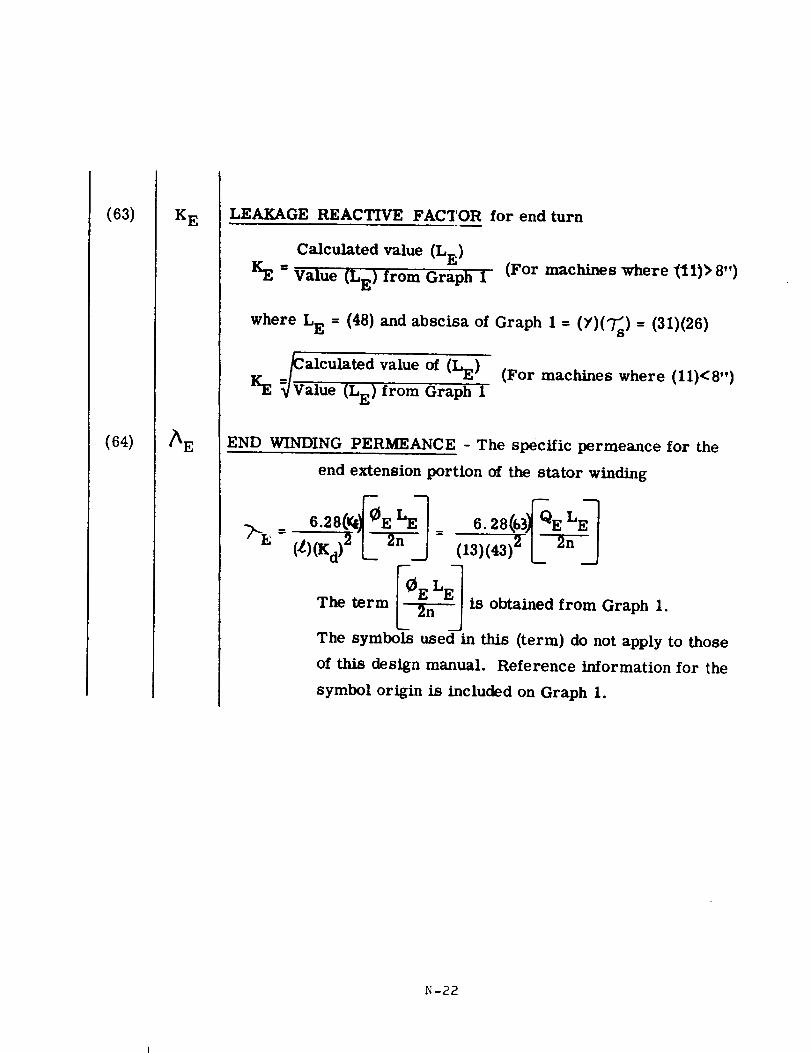
K E LEAKAGE REACTIVE FACTOR for end turn
Calculated value (LE)
KE = Value (LE) from Graph I (For machines where _11)_ 8")
where L E = (48) and abscisa of Graph 1 = (Y)(_s) = (31)(26)
=_alculated value of (LE) (For machines where (11)<8")
KE _Value (LE) from Graph 1
END WINDING PERMEANCE - The specific permeance for the
end extension portion of the stator winding
The term I_:EI is obtained from Graph 1.
The symbols used in this (term) do not apply to those
of this design manual. Reference information for the
symbol origin is included on Graph 1.
N-22
(65)
_66)
(67)
(68)
(69)
K S
Ag
ge
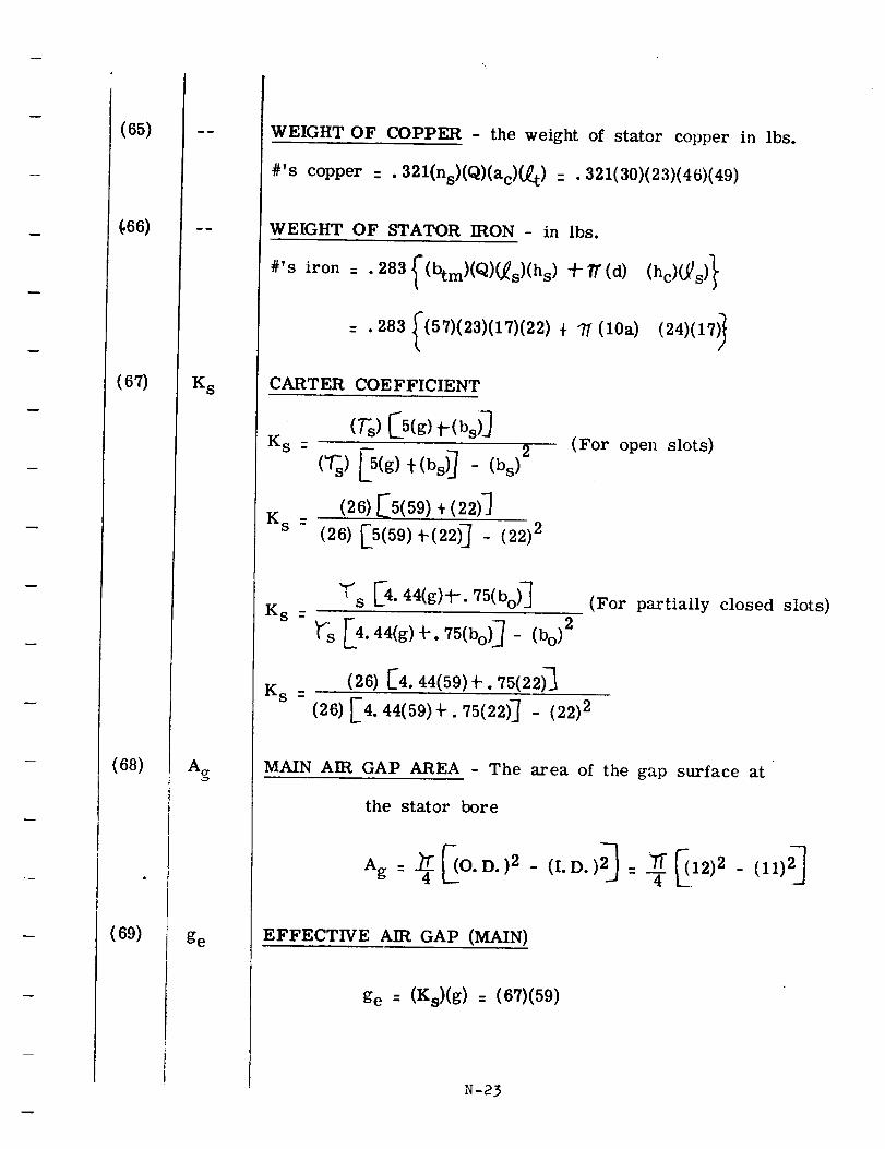
WEIGHT OF COPPER - the weight of stator copper in lbs.
#'s copper . . 321(ns)(Q)(ac)(_t) : . 321(30)(23)(46)(49)
WEIGHT OF STATOR IRON - in lbs.
#'s iron = . 283 _(btm)(Q)(_s)(hs) t/7"(d)
= .283 _(57)(23)(17)(22) + T (lOa) (24)(17)_
CARTER COEFFICIENT
Ks : 2
(26) _5(59) + (22)]
(26) [5(59) "_-(22)_ - (22) 2K S -
(For open slots)
K s :
K s -
_'s [4. 44(g)-h. 75(bo) _
_"s [4.44(g)_-. 75(bo) _ - (bo)2
(26) [4.44(59)-t-. 75(22)_
(26) [4. 44(59)-b. 75(22)J - (22) 2
(For partially closed slots)
MAIN AIR GAP AREA - The area of the gap surface at
the stator bore
Ag : _4 _O.D.)2 - (I.D.)2_ = ___12)2 - (11)2 _
EFFECTIVE AIR GAP (MAIN)
ge : (Ks)(g) : (67)(59)
N-23
(7O)
(70a)
(71)
(72)
Ag2
Ag3
C1
Cw
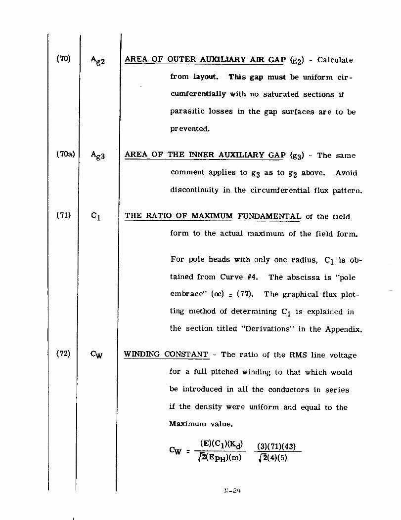
AREA OF OUTER AUXILIARY AIR GAP (g2) - Calculate
from layout. This gap must be uniform cir-
cumferentially with no saturated sections if
parasitic losses in the gap surfaces are to be
prevented.
AREA OF THE INNER AUXILIARY GAP (g3) - The same
comment applies to g3 as to g2 above. Avoid
discontinuity in the circumferential flux pattern.
THE RATIO OF MAXIMUM FUNDAMENTAL of the field
form to the actual maximum of the field form.
For pole heads with only one radius, C 1 is ob-
tained from Curve #4. The abscissa is "pole
embrace" (oc) = (77). The graphical flux plot-
ting method of determining C 1 is explained in
the section titled "Derivations" in the Appendix.
WINDING CONSTANT - The ratio of the RMS line voltage
for a full pitched winding to that which would
be introduced in all the conductors in series
if the density were uniform and equal to the
Maximum value.
(E)(C1)(K d)
C W = _'-2(EpR)(m )
(3)(71)(43)
(_(4)(5)
(73)
(74)
(75)
(76)
Cp
CM
Cq
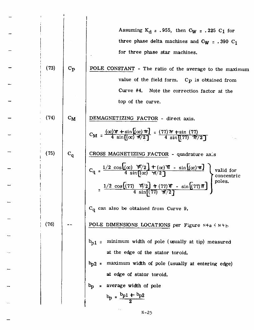
Assuming K d = .955, then CW = .225 C1 for
three phase delta machines and C w = . 390 C 1
for three phase star machines.
POLE CONSTANT - The ratio of the average to the maximum
value of the field form. Cp is obtained from
Curve #4. Note the correction factor at the
top of the curve.
DEMAGNETIZING FACTOR - direct axis.
(oc)_ 4-sin_oc)_] : (77)71" _-sin (77)
CM : 4 sin[_(oc)"if/2] 4 sin_77) "F/23
CROSS MAGNETIZING FACTOR - quadrature ax:s
Cq =I/2 COS_OC) _/2] t(oc)'ft - sin_oc)_ff] "
4 sin[(oc) "11"/23
1//2 cos_77) _//2] "l" (77)_" - sin_77)_" 1
4 sin_77) W/2]
Cq can also be obtained from Curve 9.
valid for
concentric
poles.
POLE DIMENSIONS LOCATIONS per Figure N_+a _ N_b
bpl =
bp2 =
minimum width of pole (usually at tip) measured
at the edge of the stator toroid.
maximum width of pole (usually at entering edge)
at edge of stator toroid.
average width of pole
2
N-25
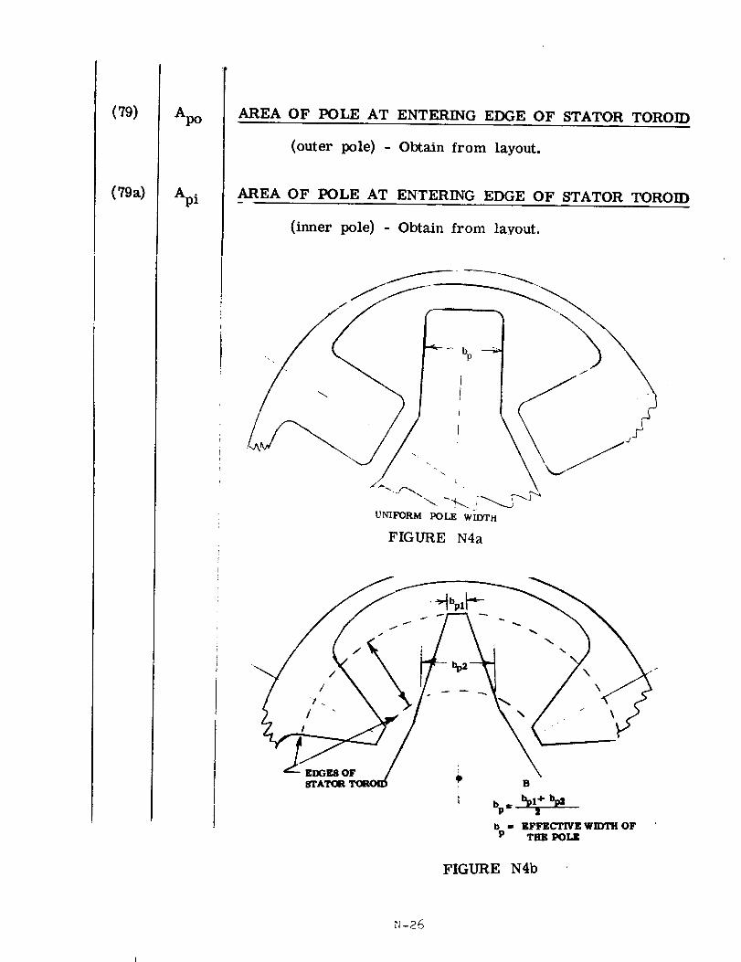
(79)
(79a)
Apo
Api
AREA OF POLE AT ENTERING EDGE OF STATOR TOROID
(outer pole) - Obtain from layout.
_AREA OF POLE AT ENTERING EDGE OF STATOR TOROID
(inner pole) - Obtain from layout.
-_ bp
_A._ "_ i __
UNIFORM POLE WIDTH
FIGURE N4a
STAT(I_ T(X%O _ B
|
b - EFFEL'_IVEWIIYFH OFP THE POLK
FIGURE N4b
_1-26
I
h _1
. .
FIGURE N5
N-27
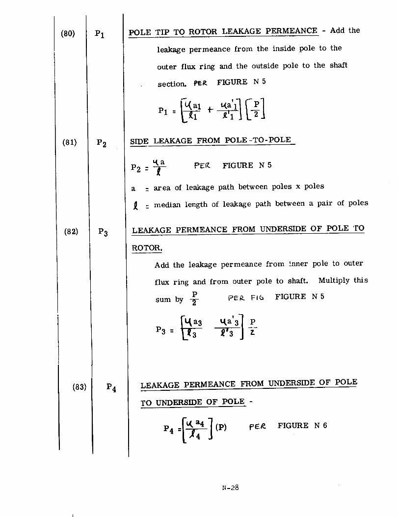
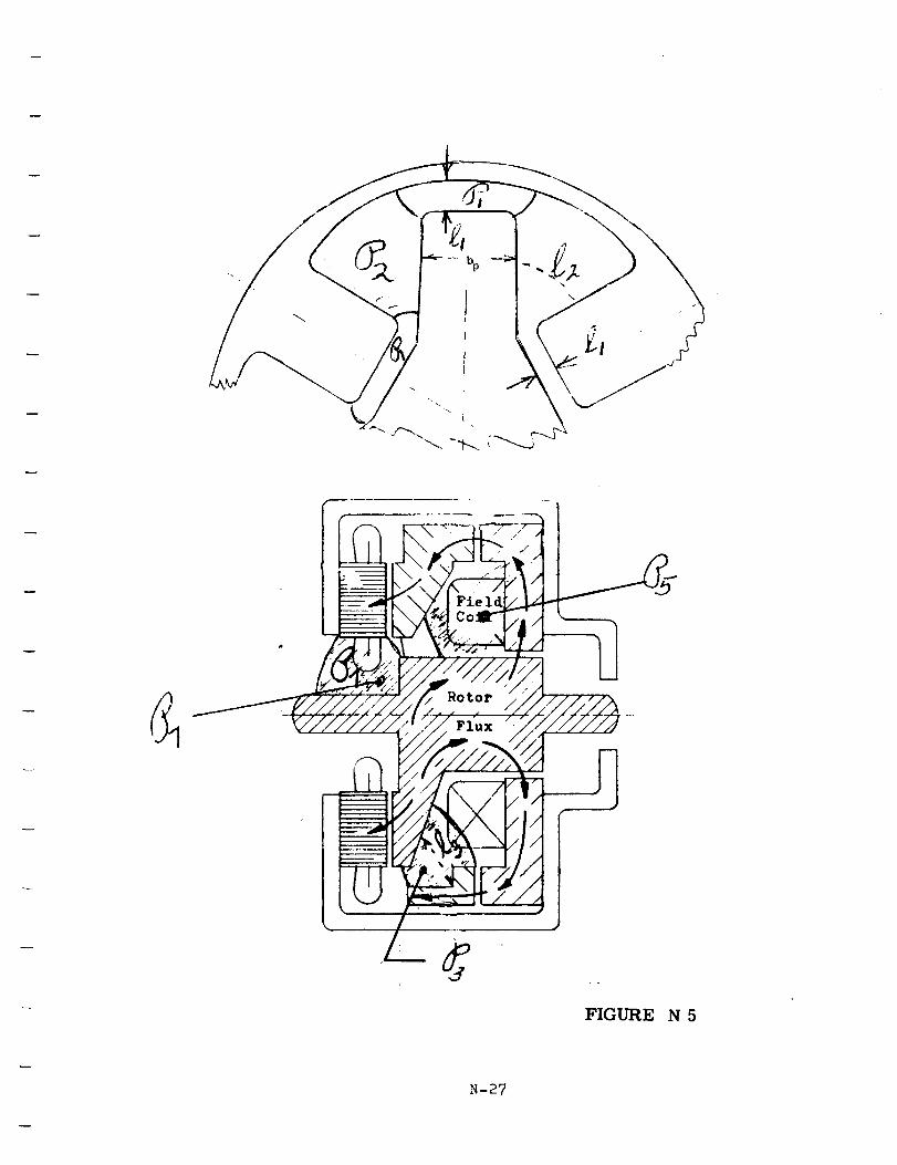
(80)
(81)
(82)
(83)
P1
P2
P3
P4
POLE TIP TO ROTOR LEAKAGE PERMEANCE - Add the
leakage permeance from the inside pole to the
outer flux ring and the outside pole to the shaft
section. PF._ FIGURE N 5
P1 = _-_
SIDE LEAKAGE FROM POLE-TO-POLE
q. a PE:_. FIGURE N 5P2 : -_'--
a = area of leakage path between poles x poles
: median length of leakage path between a pair of poles
LEAKAGE PERMEANCE FROM UNDERSIDE OF POLE 'tO
ROTOR.
Add the leakage permeance from inner pole to outer
flux ring and from outer pole to shaft. Multiply this
Psum by T PEP. FIC_
P3: _I -_-
FIGURE N 5
LEAKAGE PERMEANCE FROM UNDERSIDE OF POLE
TO UNDERSIDE OF POLE -
pE_ FIGURE N 6
N-28
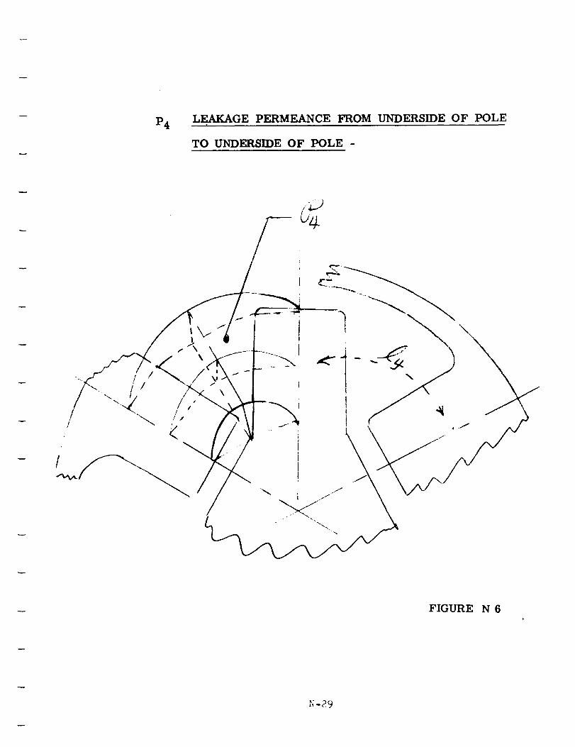
P4LEAKAGE PERMEANCE FROM UNDERSIDE OF POLE
T
TO UNDERSIDE OF POLE -
FIGURE N 6
_;-29
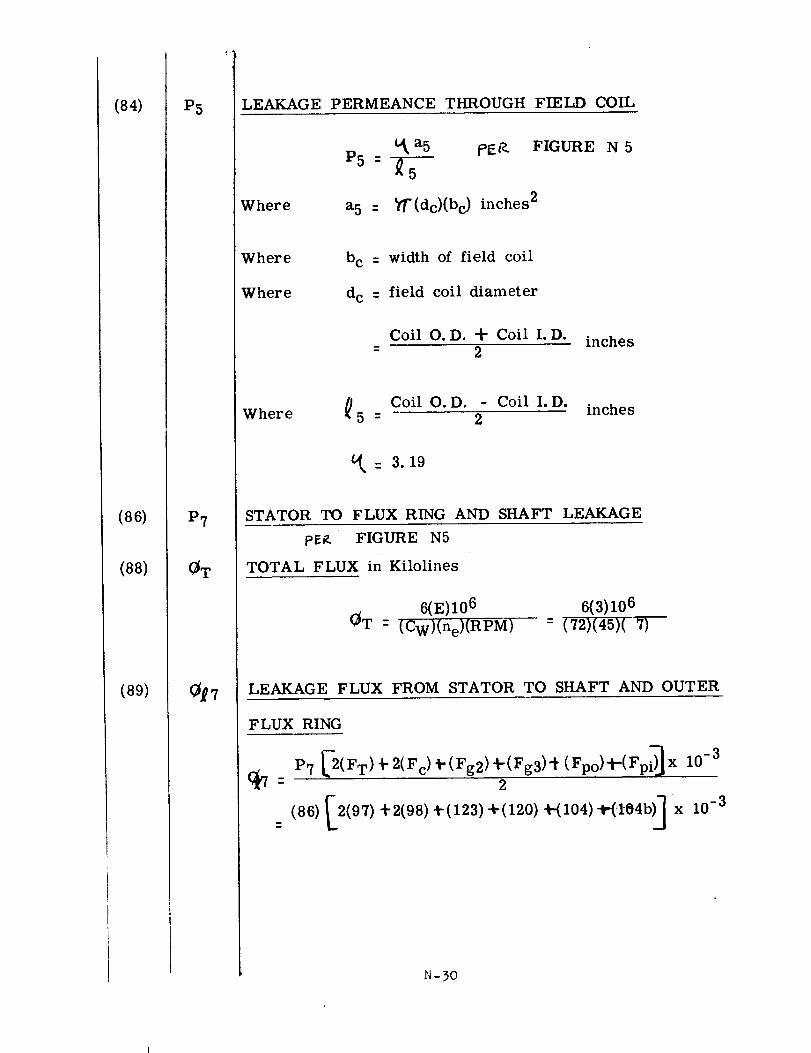
(84)
(86)
(88)
(89)
P5
P7
_T
_7
LEAKAGE PERMEANCE THROUGH FIELD COIL
Where
t_ a 5 t_r% FIGURE N 5
P5 = -_5
a 5 : _]r'(dc)(bc) inches 2
Where
Where
b c = width of field coil
d c - field coil diameter
Coil O.D. d- Coil I.D. inches= 2
Where _ 5 -Coil O.D. - Coil I.D.
inches
t_: 3.19
STATOR TO FLUX RING AND SHAFT LEAKAGE
pER FIGURE N5
TOTAL FLUX in Kilolines
6(E)106
(_T : (Cw)(ne)(RPM)
6(3)10 6
= (72)(45)(7)
LEAKAGE FLUX FROM STATOR TO SHAFT AND OUTER
FLUX RING
P7 _2(FT) _"2(Fc)_" (Fg2)_-(Fg3)'_ (Fpo)_-(Fpi)_ x 10-3
2
[ ,](86) 2(97)+2(98)t-(123)+(120)-t-(104)-_(t04b x 10-3
_-3o
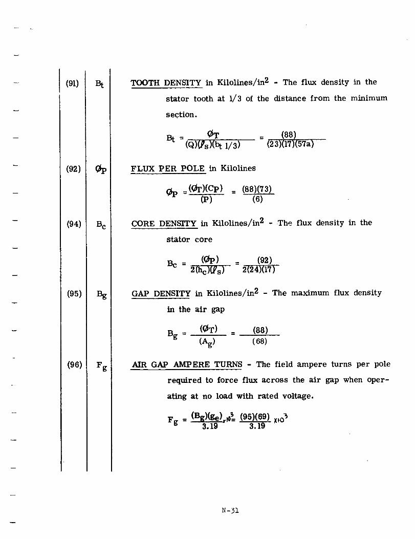
(91)
(92)
(94)
(95) I
(96)
Bt
B e
B_
Fg
TOOTH DENSITY in Kilolines/in 2 - The flux density in the
stator tooth at 1/3 of the distance from the minimum
section.
(_T = (88)
Bt = (_)_s)(b t 1/3) (23)(17)(57a)
FLUX PER POLE in Kilolines
: (_)(cp) = (88)(73)(P) (6)
CORE DENSITY in FAlolines/in 2 - The flux density in the
stator core
Bc = ((_) = (92)2(hc)_s) 2(24)(17)
GAP DENSITY in Kilolines/in 2 - The maximum flux density
in the air gap
Bg = ((_T) = (88)
(Ag) (68)
AIR GAP AMPERE TURNS - The field ampere turns per pole
required to force flux across the air gap when oper-
ating at no load with rated voltage.
Fg = (Bg)(ge),lo_ (95)(69) XlO"_3.19 3.19
N-31
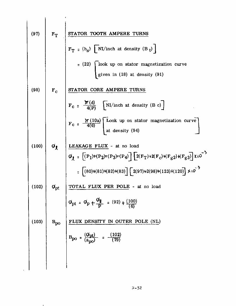
(97)
(98)
(100)
(102)
(lO3)
F T
F e
0t
Opt
Bpo
STATOR TOOTH AMPERE TURNS
F T : !hs) _Nl/inch at density (B t)]
= (22) _ look up on stator magnetization curve
!_given in (18) at density (91)
STATOR CORE AMPERE TURNS
tr(d)Fc _ 4(P)
Fc =
NI/inch at density (B c)]
(lOa) FLook up on stator magnetization
4(6) _at density (94)
LEAKAGE FLUX - at no load
-5
= _80)+(81)_82).83)] _2(97)+2(98)+(123),(12_ /,,O
TOTAL FLUX PER POLE - at no load
Opt : 0p-[-0_p = (92)_.!_
FLUX DENSITY IN OUTER POLE (NL)
(lO2)
N-32
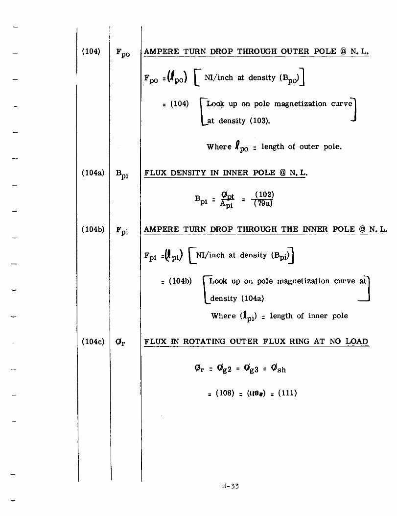
(lO4)
(104a)
(104b)
(i04c)
Fpo
Bpi
Fpi
(_r
AMPERE TURN DROP THROUGH OUTER POLE @ No L,
_oI_o)[_J_nc.at,o_.,,__l
10,I1 okuponm netizOionL at density (103).
Where _po " length of outer pole.
FLUX DENSITY IN INNER POLE @ N, L.
Bp i _ (102)= Ap i =
AMPERE TURN DROP THROUGH THE INNER POLE @ N, L,
Fpi--_pi) E NI/inch at density (Bpi) _
c10,b ookupon m netizationc voLdensity (104a)
Where (_pi) -- length of inner pole
FLUX IN ROTATING OUTER FLUX RING AT NO LOAD
Or - Og2 = Og3 - (_sh
= (108) : (lie.) = (111)
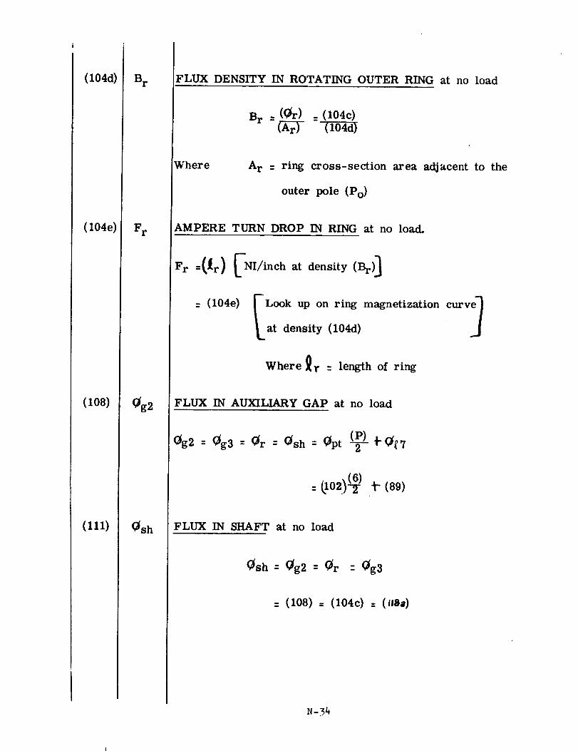
(104d)
(104e)
(lO8)
(111)
S r
F r
Og2
Osh
FLUX DENSITY IN ROTATING OUTER RING at no load
B r =(Or) = (104c)
(Ar)
Where A r = ring cross=section area adjacent to the
outer pole (Po)
AMPERE TURN DROP IN RING at no load.
Fr =(_r) _NI/inch at density (Br) _
_,,o4, onr,._. at density (104d)
Where _r = length of ring
FLUX IN AUXILIARY GAP at no load
0g2 = 0g3 = 0r = 0sh = Opt (-_)- _'(_7
= _102)(_ _-(89)
FLUX IN SHAFT at no load
0sh = 0g2 = Or = Og3
= (108) = (104c) = (liSa)
N=34
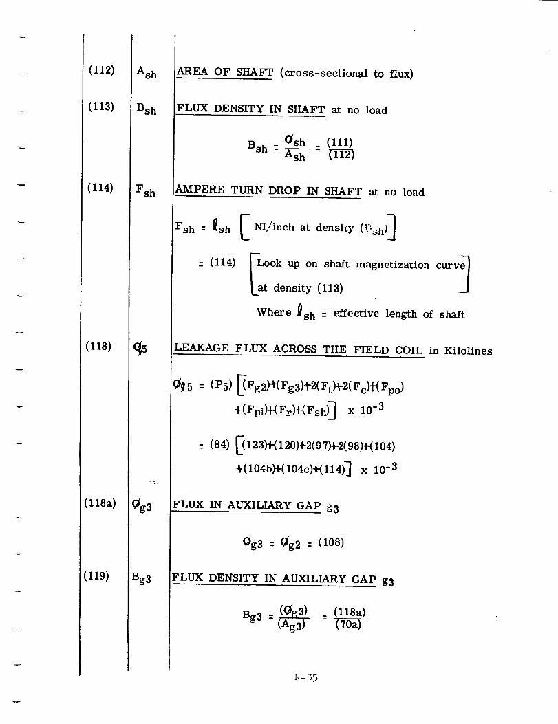
(112)
(113)
(114)
(118)
(118a)
(119)
Ash
Bsh
Fsh
(_5
(_g3
Bg3
AREA OF SHAFT (cross-sectional to flux)
FLUX DENSITY IN SHAFT at no load
_sh _ (111)
Bsh-
AMPERE TURN DROP IN SHAFT at no load
= (I14)FLook up on shaft magnetization curv_[at density (113)
Where _sh = effective length of shaft
LEAKAGE FLUX ACROSS THE FIELD COIL in Kilolines
(_5 : (P5) _Fg2)_(Fg3)_-2(F t)_-2(F c)+(Fpo)
+(Fpi)_(Fr)_Fsh) ] x 10 -3
: (84) _123)_120)4-2(97)_-2(98)_104)
4(104b)_(104e)+(l14)] x 10 -3
FLUX IN AUXILIARY GAP g3
0g3 : (_g2 : (108)
FLUX DENSITY IN AUXILIARY GAP g3
Bg 3 = (_ (l18a)
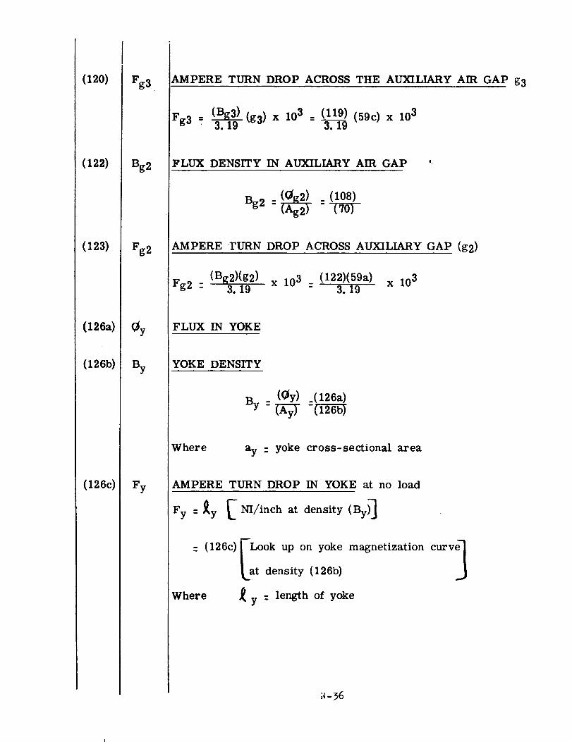
(12o)
(122)
(123)
(126a)
(126b)
(126c)
Fg3
Bg2
Fg2
0y
By
Fy
AMPERE TURN DROP ACROSS THE AUXILIARY AIR GAP g3
Fg 3 _ (Bg3)3.19(g3) x 103 - (119)3.i.9 (59c) x 103
FLUX DENSITY IN AUXILIARY AIR GAP '
AMPERE TURN DROP ACROSS AUXILIARY GAP (g2)
(Bg2)(g2)Fg2 : 3. 19
x 103 _ (122)(59a) x 1033. 19
FLUX IN YOKE
YOKE DENSITY
WhereaT - yoke cross-sectional area
AMPERE TURN DROP IN YOKE at no load
Fy= _y _ NI/inch at density (By)_
: (126c)_LoOk_at densityUpon(lYOke26b)magnetization curv_
Where _ y : length of yoke
N-36
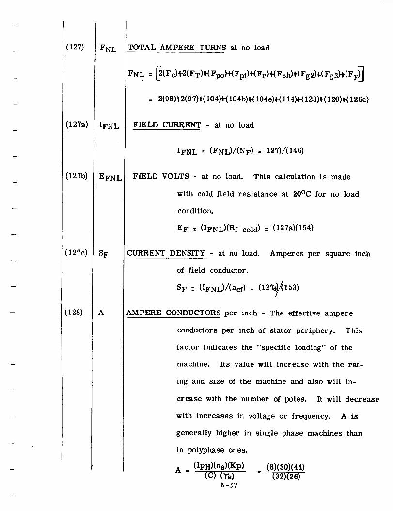
(127)
(127a)
(127b)
(127c)
(128)
FNL
IFNL
EFNL
SF
A
TOTAL AMPERE TURNS at no load
FN L = _(F c)t-2(F T)t(Fpo) #(Fpi)_( F r)_( FstO_( Fg 2)_(Fg 3)#( Fy)_
= 2(98).!-2(97)+(104)4-(104b)_(104e)t-(114)+-(123)+(120_1-(126c)
FIELD CURRENT - at no load
IFN L . (FNL)/(NF) = 127)/(146)
FIELD VOLTS - at no load. TRis calculation is made
with cold field resistance at 20°C for no load
condition.
EF : (IFNL)(Rf cold) = (127a)(154)
CURRENT DENSITY - at no load. Amperes per square inch
of field conductor.
: (IfNL)/(acf) : (127e_153)SF
AMPERE CONDUCTORS per inch - The effective ampere
conductors per inch of stator periphery. This
factor indicates the "specific loading" of the
machine. Its value will increase with the rat-
ing and size of the machine and also will in-
crease with the number of poles. It will decrease
with increases in voltage or frequency. A is
generally higher in single phase machines than
in polyphase ones.
A = (IpH)(ns)(Kp) (8)(30)(44)
(c) (rs) = (32)(26)N-37
(1291
(130)
X
x_
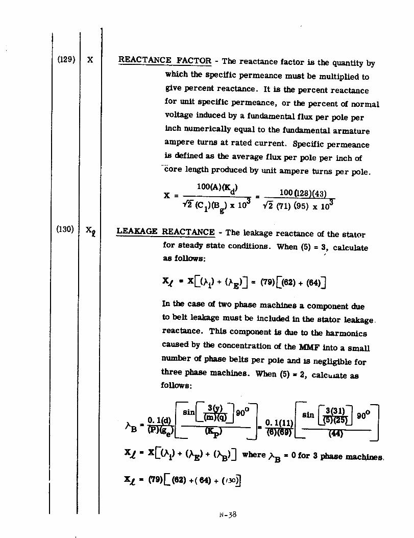
REACTANCE FACTOR - The reactance factor is the quantity by
which the specific permeance must be multiplied to
give percent reactance. It is the percent reactance
for unit specific permeance, or the percent of normal
voltage induced by a fundamental flux per pole per
inch numerically equal to the fundamental armature
ampere turns at rated current. Specific permeance
is defined as the average flux per pole per inch of
core length produced by unit ampere turns per pole.
100(A)(K d)x = = I00(128)(43)
_- (C1)(B _ x 103 "/_ (71) (95) x 103
LEAKAGE REACTANCE - The leakage reactance of the stator
for steady state conditions. When (5) = 3, calculate
as follows:
In the case of two phase machines a component due
to her leakage must be included in the stator leakage
reactance. This component is due to the harmonics
caused by the concentration of the MMF into a small
number of phase belts per pole and ls negligible for
three phase machines. When (5) = 2, calct, mte as
follows:
X_ = X[(_i ) + (_E) + ()_B) ] where _B " 0 for 3 phase nm, c .hines,
i_-38

(131)
(132)
(133)
(134)
Xad
Xaq
Xd
Xq
REACTANCE - direct axis - This is the fictitious reactance
due to armature reaction in the direct axis.
Xad =• 9 (ne)(Iph)(C m )(K d)
P[2(F g)+(Fg2)+(Fg3) ] x 100
• 9( 45)( 8 )(74 )( 43)
Xad = 612(96)+(123)+(120)] x 100
REACTANCE - Quadrature axis - This is the fictitious
reactance due to armature reaction in the quadrature
axis.
(Cq)(Xad!
Xaq = (Cm)(Cl)
(75)(131)Xaq = (74)(71)
SYNCHRONOUS REACTANCE - direct axis - the steady state
short circuit reactance in the direct axis•
Xd = (X L) + (Xad) = (130) + (131)
SYNCHRONOUS REACTANCE - quadrature axis - The steady
state short circuit reactance in the quadrature axis.
Xq = (Xl) + (Xaq) = (130) + (132)
N-39
(145)
(146)
(147)
(148)
(149)
V r
NF
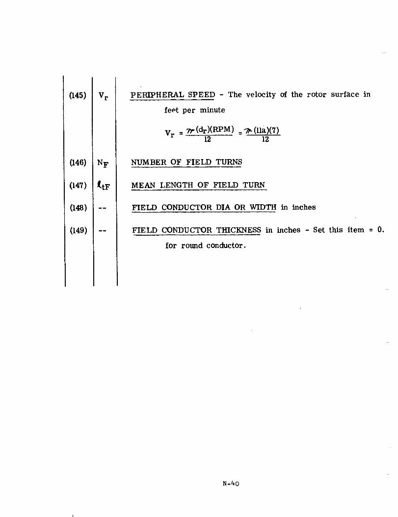
PERIPHERAL SPEED - The velocity of the rotor surface in
fept per minute
Vr = 7_(dr)(RPM) =7_(11a)(7)12 12
NUMBER OF FIELD TURNS
MEAN LENGTH OF FIELD TURN
FIELD CONDUCTOR DIA OR WIDTH in inches
FIELD CONDUCTOR THICKNESS in inches - Set this item = 0.
for round conductor.
N-40
(150) Xf°C
(151) pf
(152) !,,,Of
_ (hot)
(153) acf
(154) Rf
(cold)
(155) Rf(hot)
(156) --
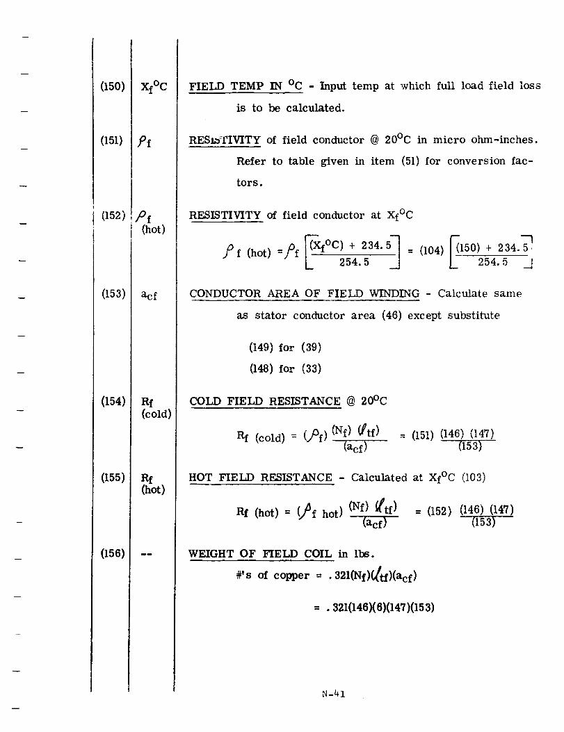
FIELD TEMP IN °C - Input temp at which full load field loss
is to be calculated.
RESISTIVITY of field conductor @ 20°C in micro ohm-inches.
Refer to table given in item (51) for conversion fac-
tors.
RESISTIVITY of field conductor at Xf°C
L._ 25-4.5 = (104) _150 .... 4.5,._],
CONDUCTOR AREA OF FIELD WINDING - Calculate same
as stator conductor area (46) except substitute
(149) for (39)
(148) for (33)
COLD FIELD RESISTANCE @ 20°C
Rf (cold) = (.,)Of)(Nf)_tf)
(acf): (151) (146) (147)
(153)
HOT FIELD RESISTANCE - Calculated at Xf°C (!03)
Rf (hot) = (2f hot) (Nf) _tt-f)
(acf)
= (152) (146)(147)
(153)
WEIGHT OF FIELD COIL in Ibs.
#'s of copper = .321(Nf)_tf)(acf )
= . 321(146)(6)(147)(153)
N-41
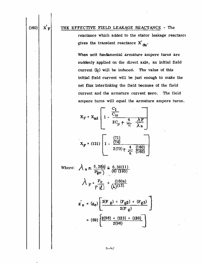
(160) X' F THE EFFECTIVE FIELD LEAKAGE REACTANCE - The
reactance which added to the stator leakage reactanc_
gives the transient reactance X' du"
When unit fundamental armature ampere turns are
suddenly applied on the direct axis, an initial field
current (If) will be induced. The value of this
initial field current will be just enough to make the
net flux interlinking the field because of the field
current and the armature current zero. The field
ampere turns will equal the armature ampere turns.
XF:
2Cp .; ,a.J
Where: A 6.3_d._ - 6.38(11)a _" D
P_e') (6) (160)
: Pe : (160a)
/_ F _ _[----_ @)(13) "
T
ge= (ge)__2(Fg) + (Fg2)+ (Fg3) 1
2(F g)
= (69)[2(96) + (123) + (120)"_2(96)
N-42
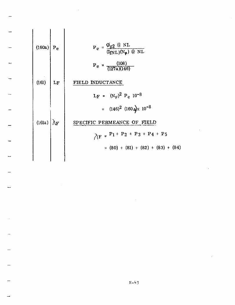
(160a)
(161)
(161a)
Pe
LF
hF
Pe = __g2__@ NL
(IfNL)(N_) @ NL
P e = (108)(127a)(146)
FIELD INDUCTANCE
LF = '(NF)2 Pe 10-8
= (146) 2 (160_x 10 -8
SPECIFIC PERMEANCE OF FIELD
_F = P1 + P2 + P3 + P4 + P5
= (80) + (81) + (82) + (83) + (84)
N-43
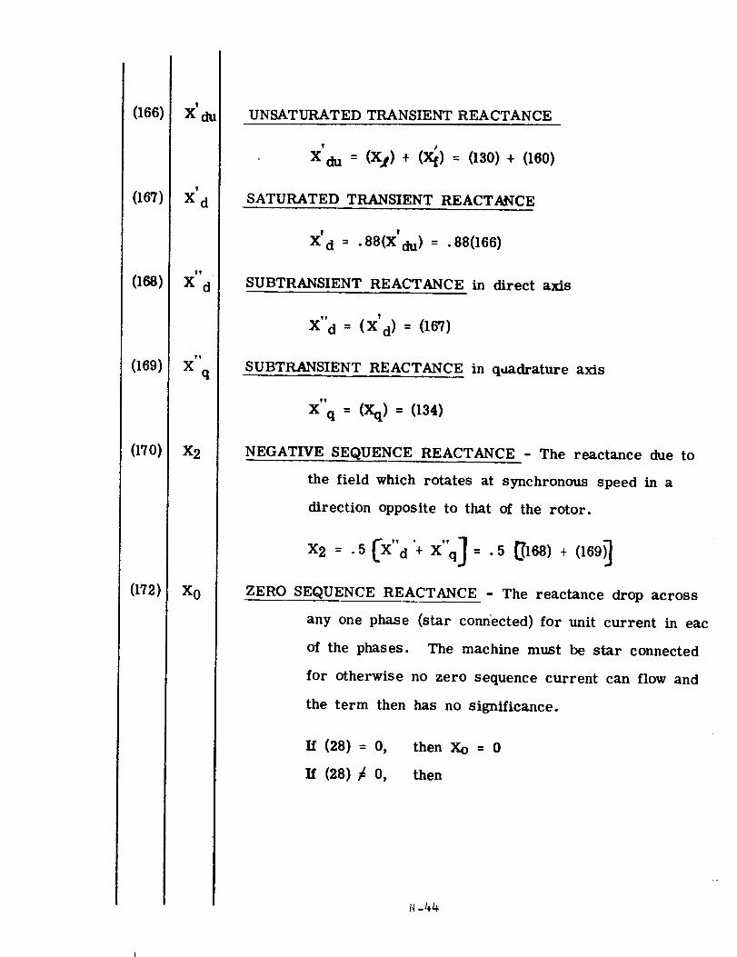
(166)
(167)
(168)
(169)
(17o)
(172)
t
Xdu
!
Xd
tt
X d
t!
Xq
X2
X0
UNSATURATED TRANSIENT REACTANCE
f J
X du = (X I) + (Xf) = (130) + (160)
SATURATED TRANSIENT REACTANCE
! t
X d = .88(X du) = .88(166)
SUBTRANSIENT REACTANCE in direct axis
X" d = (X'd)= (167)
SUBTRANSIENT REACTANCE in qaadrature axis
_Y
X q = (Xq)= (134)
NEGATIVE SEQUENCE REACTANCE - The reactance due to
the field which rotates at synchronous speed in a
direction opposite to that of the rotor.
x,._-._Cx"_+x",j=.__,o_,+_,o_,]ZERO SEQUENCE REACTANCE - The reactance drop across
any one phase (star connected) for unit current in eac
of the phases. The machine must be star connected
for otherwise no zero sequence current can flow and
the term then has no significance.
i_ (28) = o,
i_ (28) _ o,
then Xo = 0
then
N-44
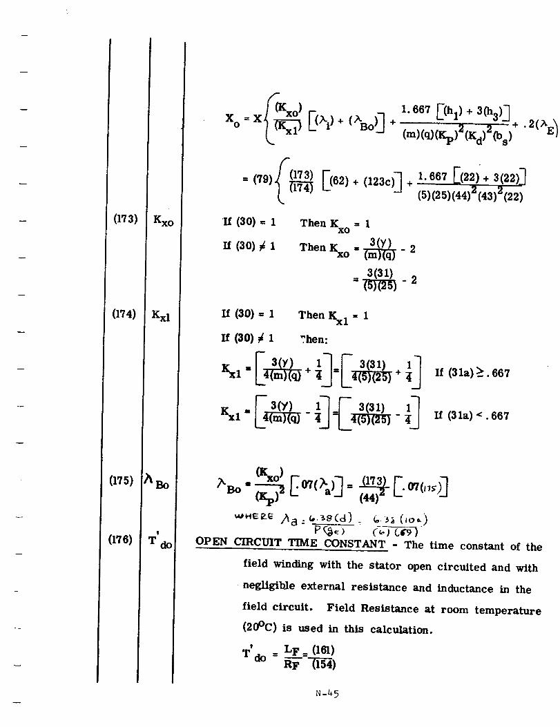
(173)
(174)
(175)
(17e)
Kxl
5(Kxo ) 1.667 E(hl) + 3(h3) 3
= (79)(_ E(62)+ (123C)]
1. 667 E(22) + 3(22)]
(5)(25)(44) 2 (43) 2 (22)
Then K = 1xo
ThenKxo=_- 2
=_ -2
If (30)= I Then Kxl = 1
If (30) ¢ 1 ?hen:
[- 3(y)"'"
H (31a) __. 667
ff (31a) 4. 667
(_o)
OPEN C_CluTJT TJ24[IR.CONSTKNT - The time constant of the
field winding with the stator open circuited and with
negtigib]e external resistance and inductance in the
field circuit. Field Resistance at room temperature
(20°C) is used in this calcuiation.
' = L F _ (161)T do _-- 1-'(i-_)
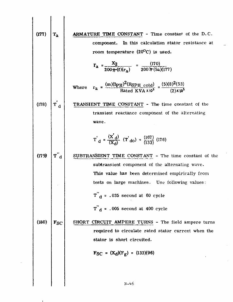
(177)
(178)
(17_)
(18o)
T a
T
T d
TV
Td
FSC
ARMATURE TIME CONSTANT - Time constant of the D.C.
component. In this calculation stator resistance at
room temperature (20°C) is used.
ra = x2 __ 070)
20011-(f)(ra) 2007t (5a)(177)
(m)(IpH)2(RSPH cold) (5)(8)2(53)
Where ra = Rated KVAXlO _ = (2)xW _
TRANSIENT TIME CONSTANT - The time constant of the
transient reactance component of the alternating
wave.
' (X'd) (167)
Td :_ (T'do) : _ (176)
SUBTRANSIENT TIME CONSTANT - The time constant of the
subtransient component of the alternating wave.
This value has been determined empirically from
tests on large machines. Use following values:
t!
T d = -035 second at 60 cycle
_t
T d = .005 second at 400 cycle
SHORT CIRCUIT AMPERE TURNS - The field ampere turns
required to circulate rated stator current when the
stator is short circuited.
FSC = (Xd)(Fg) = (133)(96)
N-46
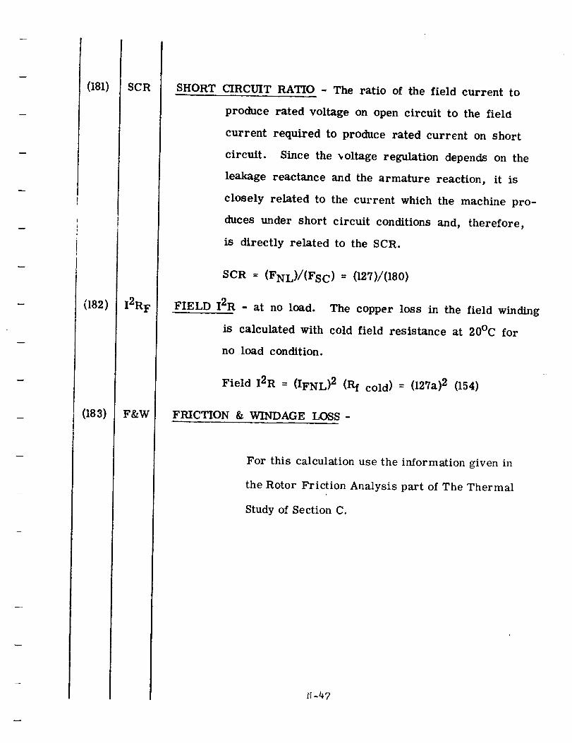
(181)
(182)
(183)
SCR
I2RF
F&W
SHORT CIRCUIT RATIO - The ratio of the field current to
produce rated voltage on open circuit to the field
current required to produce rated current on short
circuit. Since the _oltage regulation depends on the
leakage reactance and the armature reaction, it is
closely related to the current which the machine pro-
duces under short circuit conditions and, therefore,
is directly related to the SCR.
SCR = (FNL)/(Fsc) = (12'/)/(180)
FIELD I2R - at no load. The copper loss in the field winding
is calculated with cold field resistance at 20°C for
no load condition.
Field I2R : (IFNL) 2 (Rf cold) : (127a)2 (154)
FKICTION & WINDAGE LOSS -
For this calculation use the information given in
the Rotor Friction Analysis part of The Thermal
Study of Section C.
:I-47
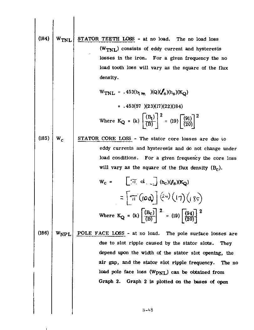
084)
(185)
(166)
WTNL
W c
WNPL
STATOR TEETH LOSS - at no load. The no load loss
(WTNL) consists of eddy current and hysteresis
losses in the iron. For a given frequency the no
load tooth loss will vary as the square of the flux
density.
WTN L = . 453(bt_ a )(Q)(fs)(hs)(KQ)
= .453(57 )(23)(17)(22)(184)
Where KQ = (k) I-_l 2 = (19) _I 2
STATOR CORE LOSS - The stator core losses are due to
eddy currents and hysteresis and do not change under
load conditions. For a given frequency the core loss
will vary as the square of the flux density (Bc).
Where KQ = (k) = (19)
POLE FACE LOSS - at no load. The pole surface losses are
due to slot ripple caused by the stator slots. They
depend upon the width of the stator slot opening, the
air gap, and the stator slot ripple frequency. The no
load pole face loss (WpNL) can be obtained from
Graph 2. Graph 2 is plotted on the bases of open
N-48
slots. In order to apply this curve to partially open
slots, substitute b o for b s. For a better understand-
ing of Graph 2, use the following sample:
K 1 as given on Graph 2 is derived empirically and
depends on lamination material and thickness. Those
values given on Graph 2 have been used with success.
K 1 is an input and must be specified. See Item (187)
for values of K 1.
K 2 is shown as being plotted as a function of (BG) 2" 5
Also note that upper scale is to be used. Another
note in the lower right hand corner of graph indicates
that for a solid line ( ), the factor is read
from the left scale, and for a broken or dashed line
(_____ ), the right scale should be read.
For example, find K 2 when B G = 30 kilolines. First
locate 30 on upper scale. Read down to the inter-
section of solid line plot of K 2 = f(BG) 2"5. At this
intersection read the left scale for K 2. K 2 = . 28.
Also refer to Item (188) for K 2 calculations.
K 3 is shown as a solid line plot as a function of
(FsLT)I. 65. The note on this plot indicates that the
upper scale X 10 should be used. Note FSL T = slot
frequency. For an example, find K 3 when FSL T =
1000. Use upper scale X 10 to locate 1000. Read
down to intersection of solid line plot of K 3 =
f(FSLT)I. 65 At this intersection read the left scale
:_-49
(187) K1
for K 3. K 3 = 1.35. Also refer to Item (189) for
K 3 calculations.
For K 4 use same procedure as outlined above except
use lower scale. Do not confuse the dashed line in
this plot with the note to use the right scale. The
note does not apply in this case. Read left scale.
Also refer to Item (190) for K 4 calculations.
For K 5 use bottom scale and substitute b o for b s
when using partially closed slot. Read left scale
when using solid plot. Use right scale when using
dashed plot. Also refer to Item (191) for K 5 cal-
culations.
For K 6 use the scale attached for C 1 and read K 6
from left scale. Also refer to Item (192) for K 6
calculations.
The above factors (K2) , (K3) , (K4) , (Ks), (K6)can
also be calculated as shown in (188), (189), (190),
(191), (192) respectively.
WpNL : 7_d)(,_(K 1)(K 2 )(K 3)(K4)(K5)(K6)
=7_-(11 )(13 )(187 )(188 )(189 )(190 )(191 )(192 )
K 1 is derived empirically and depends on lamination material
and thickness. The values used successfully for K 1
are shown on Graph 2. They are:
N-50
(188)
(189)
(190)
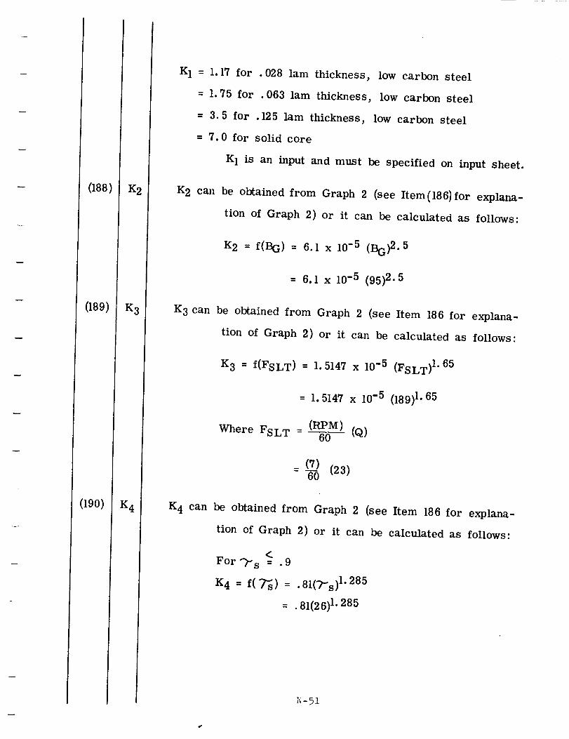
K 1 = 1.17 for .028 lam thickness, low carbon steel
= 1.75 for . 063 lam thickness, low carbon steel
= 3.5 for .125 lam thickness, low carbon steel
= 7.0 for solid core
K 1 is an input and must be specified on input sheet.
K 2 can be obtained from Graph 2 (see Item (186) for explana-
tion of Graph 2) or it can be calculated as follows:
K2 = f(BG) = 6.1 x 10 -5 (BG)2.5
= 6.1 x 10 -5 (95) 2. 5
K 3 can be obtained from Graph 2 (see Item 186 for explana-
tion of Graph 2) or it can be calculated as follows:
K3 = f(FSLT) = 1.5147 x 10 -5 (FSLT) 1"65
= 1.5147 x 10 -5 (189)1.65
(RPM)Where F S LT = 60 (Q)
= (7) (23)60
K 4 can be obtained from Graph 2 (see Item 186 for explana-
tion of Graph 2) or it can be calculated as follows:
For_" s = .9
K4 = f(7"ss) = .81(-2-s) 1"285
= .81(26)1.285
r_-51
(191) K5
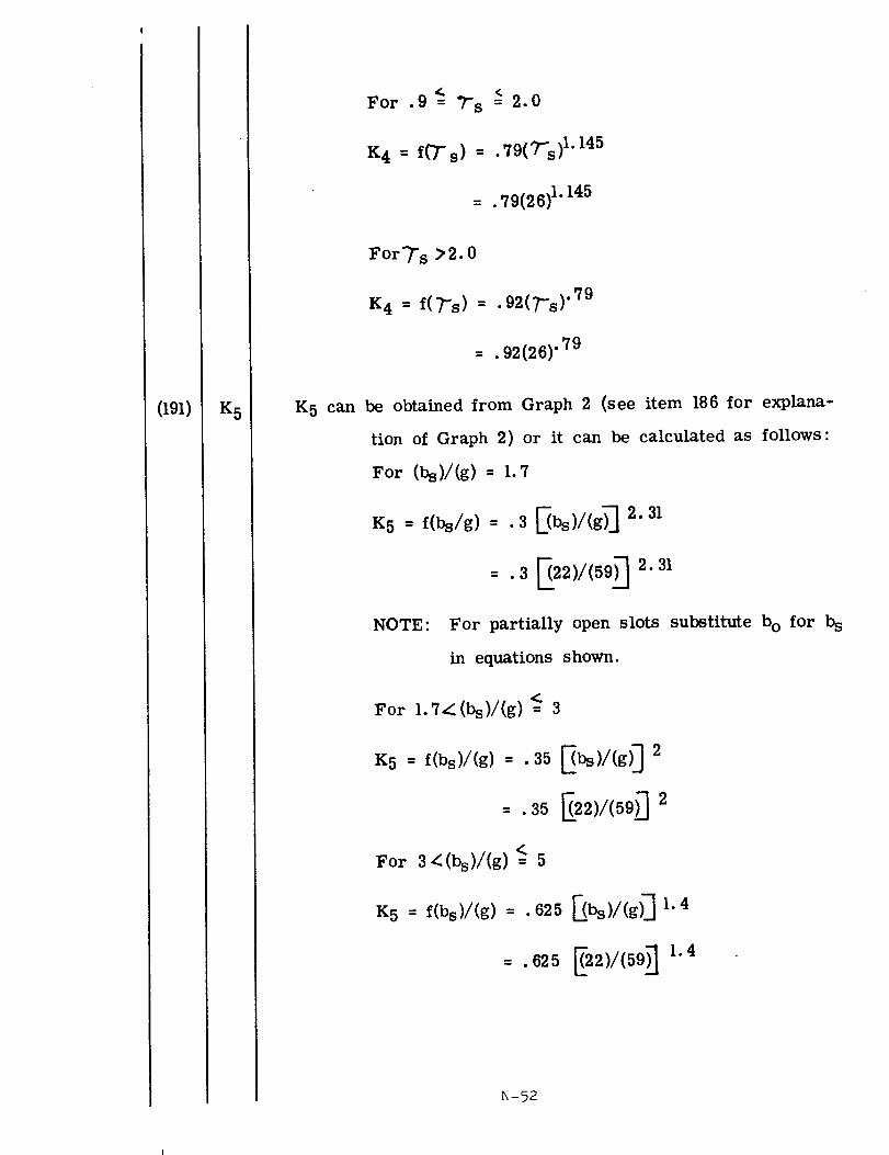
For .9_= ?-s _ 2.0
K 4 = f(Ts) = "79(T's) 1"145
_- ._9(26) 1.145
For"/" s ;_2.0
K4 = f('_'s) = • 92(_'s)" 79
= . 92(26)" 79
K 5 can be obtained from Graph 2 (see item 186 for explana-
tion of Graph 2) or it can be calculated as follows:
For (bs)/(g)= 1._
K5 : f(bs/s) : •3 I_b_)/(g_ 2.31
=.3 E(22)/(59)-7 2" 31
NOTE: For partially open slots substitute bo for b S
in equations shown.
For 1.7_(bs)/(g)<= 3
K5 : f(bs)l(g) : .35 _)/(g)_ 2
= .35 [(22)I(59)_ 2
For 3_(bs)/(g) <= 5
K 5 = f(bs)/(g ) = . 625 [-(bs),/(g) _ 1.4
- . 625 _22)I(59)-] 1.4
N-52
(192)
(194)
(195)
(196)
K6
I2R
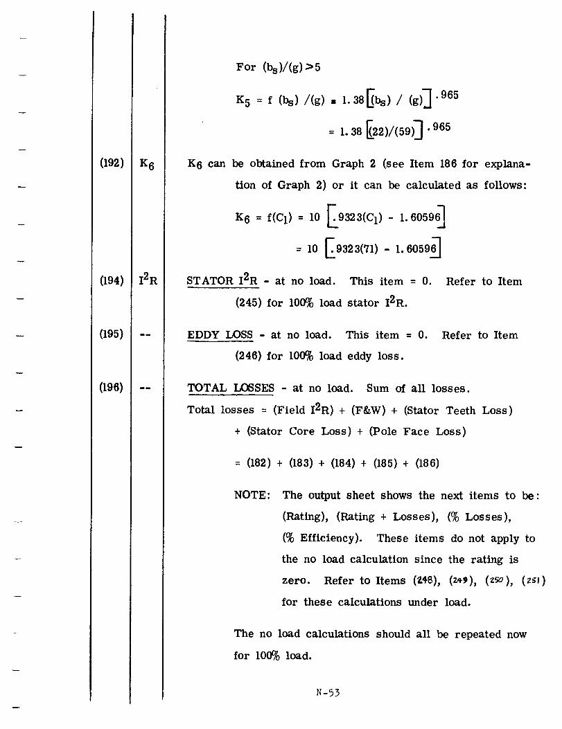
For (bs)/(g) >5
K5 = f (bs) /(g) = 1.38Ebs) / (g)_.965
= 1.38 _22)/(59)_"965
K 6 can be obtained from Graph 2 (see Item 186 for explana-
tion of Graph 2) or it can be calculated as follows:
K 6 = f(C1)= I0 _.9323(C1) - 1.60596_
= 10 E9323(71)- 1.60596_
STATOR I2R - at no load. This item = 0. Refer to Item
(245) for 100% load stator I2R.
EDDY LOSS - at no load. This item = 0.
(246) for 100% load eddy loss.
Refer to Item
TOTAL LOSSES - at no load. Sum of all losses.
Total losses = (Field I2R) + (F&W) + (Stator Teeth Loss)
+ (Stator Core Loss) + (Pole Face Loss)
= (182) + (183) + (184) + (185) + (186)
NOTE: The output sheet shows the next items to be:
(Rating), (Rating + Losses), (% Losses),
(% Efficiency). These items do not apply to
the no load calculation since the rating is
zero. Refer to Items (Z48), (z,_), (z_o), (z;I)
for these calculations under load.
The no load calculations should all be repeated now
for 100% load.
N-53
(196a)
(198)
(198a)
(207)
(213)
ed
0
_7L
G_pL
_rcel
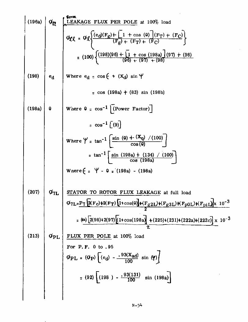
LEAKAGE FLUX PER POLE at 100% loadL
_[_ =_f (ed)(Fg)_- El(Fg) _- tCOS(FT)_-(0)](FT)_-(Fc) (Fc_
Where e d - cos_ _" (Xd) sin
= cos (198a) _- (83) sin (198b)
W ere0= PowerF ctor ]
: COS-I [(9 0
Where _V tan_ 1 [sin (0)+" (Xq)cos(0) /(100)]
=tan -I [sin (198a)cos _" (198a)(134)/ (I00)_
WnereE : _u_ 0 :'(198a) - (198a)
STATOR TO ROTOR FLUX LEAKAGE at full load
Q7L=P7 _(Fc)*2(FT)_*cos(O)]+(FgZL)+(Fg3L)t(Fp0L)t(FpiDl x 10 -3
2
: @@_(98)+2(97)_l÷cos(198a_ +(225)+(231)÷(222a)_222c)_x 10 -3
Z
FLUX PER POLE at 100% load
For P.F. 0 to .95-}
.93(Xad)(_PL : ((_P) ed) - _ sin (_
(92) [(198 ) - .93(131) a)_100 sin (198
N-54
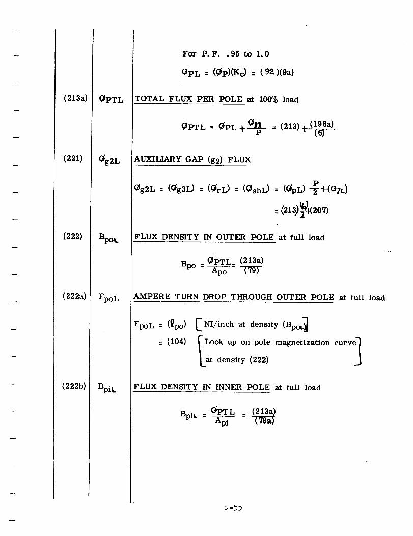
(213a)
(221)
(222)
(222a)
(222b)
0g2L
Bpot.
FpoL
Bpi t.
For P.F..95 to 1.0
0PL = (0P)(Kc) = (9_)(9a)
TOTAL FLUX PER POLE at 100% load
__p (196a)0PTL = 0PL d- = (213)_. (6)
AUXILIARY GAP (g2) FLUX
P0g2L : (0g3L) " (0rL) '- (0shL) = (0pL) -_'_-(07L)
: (213) 2o7)
FLUX DENSITY IN OUTER POLE at full load
Bp o 0PTL_ (213a)= Ap 0
AMPERE TURN DROP THROUGH OUTER POLE at full load
FpoL : (_po)
= (104)
. NI/inch at density (Bp
Look up on pole magnetization curve]
at density (222) J
FLUX DENSITY IN INNER POLE at full load
BpiL OPTL _ (213a): Ap i _-_
i'_-55
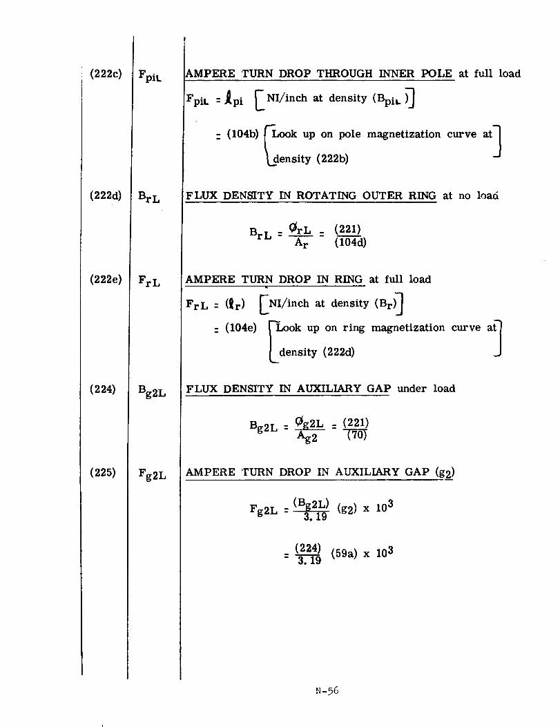
(222c)
(222d)
(222e)
(224)
(225)
FpiL
BrL
FrL
Bg2L
Fg2L
AMPERE rURN DROP THROUGH INNER POLE at full load
FpiL: _pi [NI/inch at density (Bpit.)_
-(104b) _-Look up on pole magnetization curve at]
J_density (222b)
FLUX DENSITY IN ROTATING OUTER RING at no load
Br L _ _trL _ (221)
A r (104d)
AMPERE TURN DROP IN RING at full load
FrL: (_r) [NI/inch at density (Br) _
: (104e) _Look up on ring magnetization curve a_
[density (222d)
FLUX DENSITY IN AUXILIARY GAP under load
Bg2L : _L_ : (221)_g2
AMPERE TURN DROP IN AUXILIARY GAP (g2)
(Bg2L) (g2) x 10 3Fg2L : 3. 19
(224) (59a) x 103- 3.19
N-95
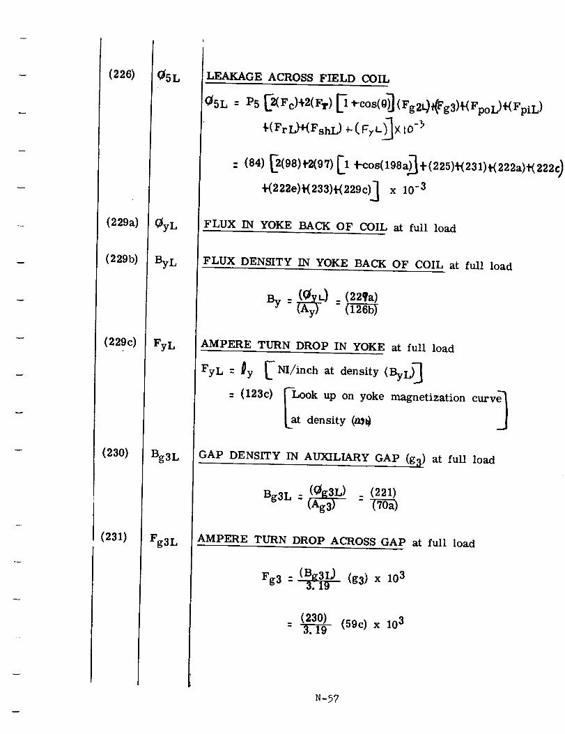
(226)
(229a)
(229b)
(229c)
(230)
(231)
05L
_yL
ByL
FyL
Bg3L
Fg3L
LEAKAGE ACROSS FIELD COIL
05L= P5 _(Fc)_2(FT)_ _-cos(0)_(Fg2_(Fg3)_(FpoL)+(FpiL)
_'(Fr L}+(FshL) _ ( gy L_X IO-_
+(222e)'¢(233)t-(229c)_ x 10 -3
FLUX IN YOKE BACK OF COIL at full load
FLUX DENSITY IN YOKE BACK OF COIL at full load
AMPERE TURN DROP IN YOKE at full load
FyL-gy [-_/_.chatdensity<ByL)]
: F,.oo onm n t ,. t onEat density (art)
GAP DENSITY IN AUXILIARY GAP (g_) at full load
Bg3L : (0g3L) : (221)(Ag3)
AMPERE TURN DROP ACROSS GAP at full load
Fg3 : (Bg3L) (g3) x 103_. 19
(230) (59c) x 103- -3T-i_
N-57
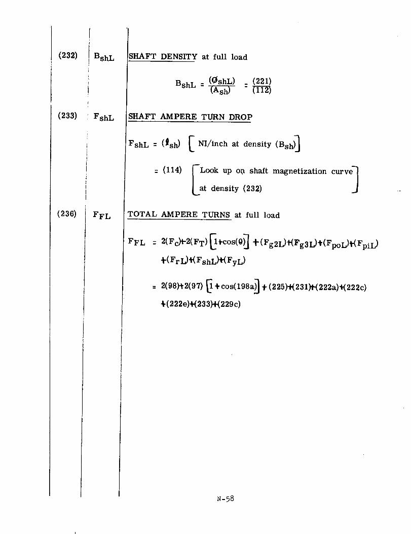
(232)
(233)
(236)
¢{
i BshL
FshL
FFL
SHAFT DENSITY at full load
BshL : ((_shL) : (221)(Ash)
SHAFT AMPERE TURN DROP
FshL = (_sh)
: (114)
N I/inch at density (Bsh)]
LOok uP o_ shaft magnetization curve 1density (232)
TOTAL AMPERE TURNS at full load
FFL : 2(Fc}_2(F T) _+cos(0)_ +(Fg2L)#(Fg3L)+(FpoL)_(FpiL )
_'(Fr I)_(FshL)_(FyL)
: 2(98)'}2(97) _ +cos(198a)] +(225)_231)P(222a)_(222c)
_(222e)+(233)+(229c)
N-58
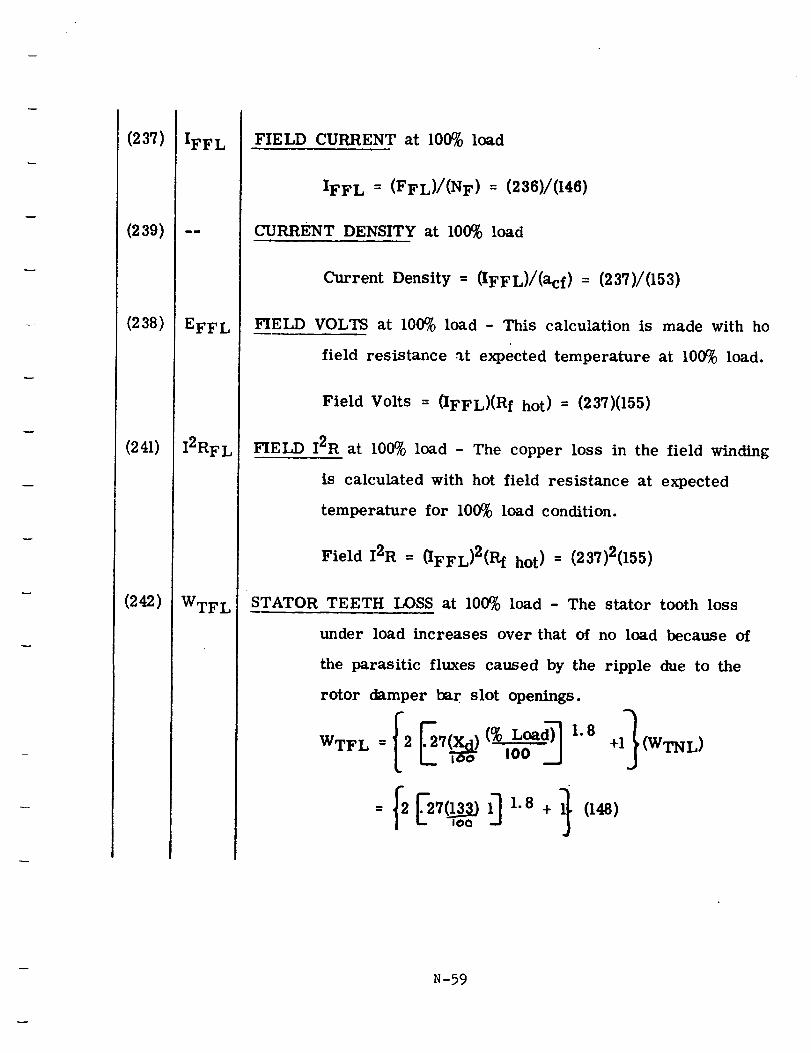
(237)
(239)
(238)
(241)
(242)
IFFL
EFFL
I2RFL
WTFL
FIELD CURRENT at 100% load
IFF L = (FFL)/(N F) = (236)/(146)
CURRENT DENSITY at 100% load
Current Density = (IFFL)/(acf) = (237)/(153)
FIELD VOLTS at 100% load - This calculation is made with ho
field resistance _t expected temperature at 100% load.
Field Volts = (IFFL)(R f hot) = (237)(155)
FIELD I2R at 100% load - The copper loss in the field winding
is calculated with hot field resistance at expected
temperature for 100% load condition.
Field I2R = (IFFL)2(Rf hot) = (237)2(155)
STATOR TEETH LOSS at 100% load - The stator tooth loss
under load increases over that of no load because of
the parasitic fluxes caused by the ripple due to the
rotor damper bar slot openings.
I00 ._J + (WTNL)
N-59
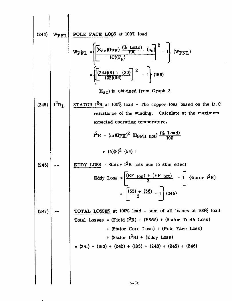
(243)
(245)
(246)
(247)
WpFL
12RL
POLE FACE LOSS at 100% load
_IFKsc)(ipH) (% Load) (ns_2+
WpFL-[L (C)(Fg) 1OU
1 (30) 2-[L (32)(96) + 1} 086)
_ (WpNL)
(Ksc) is obtained from Graph 3
STATOR 12R at 100% load - The copper loss based on the D.C
resistance of the winding. Calculate at the maximum
expected operating temperature.
12R = (m)(IPH) 2 (RSPH hot) (% Load)100
- (5)(8)2 (54)1
EDDY LOSS - Stator 12R loss due to skin effect
Eddy Loss =[EF t°P) +(EF2 hot) -l_ (Stator 12R)
= _'5); (56) - 1_ (24_,
TOTAL LOSSES at 100% load - sum of all losses at 100% load
Total Losses = (Field 12R) + (F&W) + (Stator Teeth Loss)
+ (Stator Core Loss) + (Pole Face Loss)
+ (Stator I2R) + (Eddy Loss)
= (241) + (183) + (242) + (185) + (243) + (245) + (246)
N-60
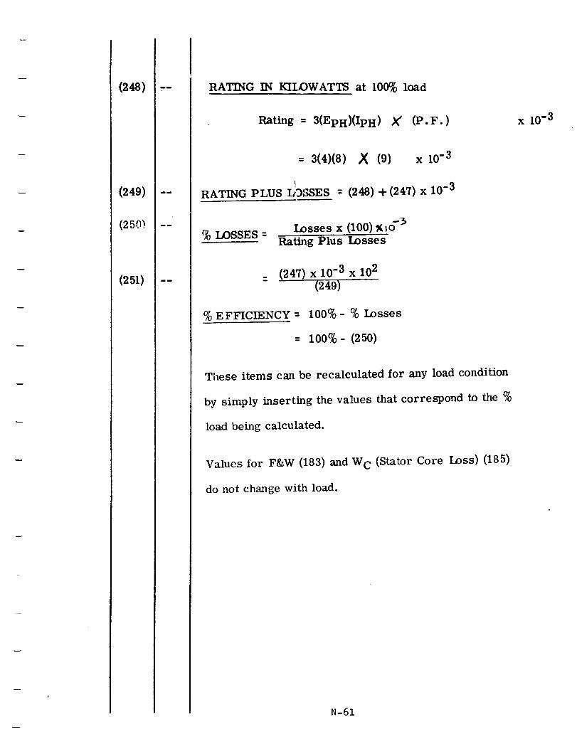
(248)
(249)
(250)
(251)
RATING IN KILOWATTS at 100% load
Rating = 3(EpH)(IpH ) X' (P.F.)
= 3(4)(8) ,_ (9) x 10-3
RATING PLUS DgSSES = (248) + (247) x 10-3
% LOSSES =Losses x (100)_(,o -_'
Rating Plus Losses
: xjS x% EFFICIENCY = 100% - % Losses
= 100%- (250)
These items can be recalculated for any load condition
by simply inserting the values that correspond to the %
load being calculated.
Values for F&W (183) and W C (Stator Core Loss) (185)
do not change with load.
N-61
x 10 -3

v
SE C TION P
!
!
!
!
i
!
|!
!
DESIGN MANUAL FOR
HOMOPOLAR INDUCTOR A-C GENERATOR
!
!
!
!
SECTION P
i
|
|
|
|
L
|
|
i
|g_
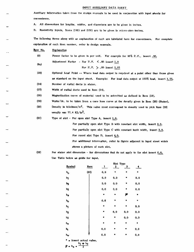
INPUT AUXILIARY DATA SHEET
Auxiliary information taken from the design manuals to be used in conjunction with input sheets for
convenience.
A. All dimensions for lengths, widths, and diameters are to be given in inches.
B. Resistivityinputs, Items (141) and (151) are to be given in micro-ohm-inches.
The following items along with an explanation of each are tabulated here for convenience.
explanation of each item number, refer to design manuals.
Rem No.
(9)
(oa)
(lO)
(14)
(15)
(IS)
(19)
(20)
(21)
(22)
For complete
Explanation
Power factor to be given in per unit. For example for 90% P.F., insert .90.
Adjustment Factor - For P.F. _ .95 insert 1.0
For P.F. _> .95 insert 1.05
Optional Load Point -- Where load data output is required at a point other than those given
as standard on the input sheet. Example: For load data output at 155% load, insert 1.55.
Number of radial ducts in stator.
Width of radial ducts used in Item (14).
Magnetization curve of material used to be submitted as defined in Item (18).
Watts/Lb. to be taken from a core loss curve at the density given in Item (20) (Stator).
Density in kilolines/in 2. This value must correspond to density used to pick Item (19)
usually use 77.4 KL/in 2.
Type of slot - For open slot Type A, insert 1.0.
For stator
Use Table
For partially open slot Type B with constant slot width, insert 2.0.
For partially open slot Type C with constant tooth width, insert 3.0.
For round slot Type D, insert 4.0.
For additional information, refer to figure adjacent to input sheet which
shows a picture of each sloL
slot dimension - for dimensions that do not apply to the slot insert 0.0.
below as guide for input.
_mbol Item
bo (22)
bl
b2
b3
bs
ho
hl
h2
h3
hs
ht
_w
* • insert actual value.bl + b3
_P= bs = 2
Slot Type1 2 3 4
0.0 * * *
0.0 0.0 * 0.0
0.0 0.0 * 0.0
0.0 0.0 * 0.0
0.0 * * *
• * * 0.0
• 0.0 0.0 0.0
• * 0.0 0.0
0.0 * * 0.0
0.0 * * 0.0
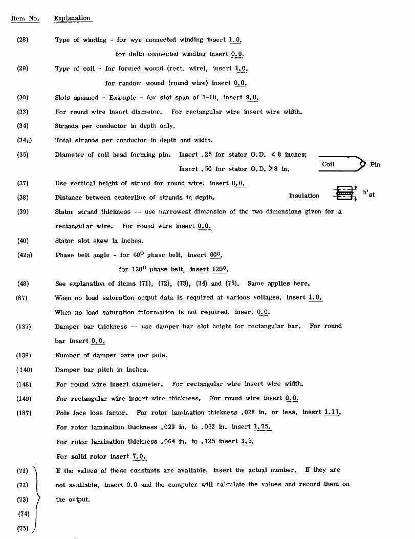
Item No. Explanation
(28)
(29)
(3o)
(33)
(34)
(34a)
(35)
(37)
(38)
(39)
(4o)
(421)
(48)
(87)
(137)
(138)
(140)
(148)
(149)
(187)
(71) _
(72)
(73)
(74)
(75)
Type of winding - for wye connected winding insert 1.0.
for delta connected winding insert 0.0.
Type of coil - for formed wound (rect. wire), insert 1.0.
for random wound (round wire) insert 0.0.
Slots spanned - Example - for slot span of 1-10, insert 9.0.
For round wire insert diameter. For rectangular wire insert wire width.
Strands per conductor in depth only.
Total strands per conductor in depth and width.
Diameter of coil head forming pin. Insert .25 for stator O.D. < 8 inches;
CoilInsert . 50 for stator O.D. )8 In.
Use vertical height of strand for round wire, insert 0.0.
Distance between centerline of strands in depth. Insulation -_
Stator strand thickness -- use narrowest dimension of the two dimensions given for a
rectangular wire. For round wire insert 0.0.
Stator slot skew in inches.
Phase belt angle - for 60 ° phase belt, insert 60o.
for 120 ° phase belt, insert 120 ° .
See explanation of items (71), (72), (73), (74) and (75). Same applies here.
When no load saturation output data is required at various voltages, insert 1.0.
When no load saturation information is not required, insert 0.0.
Damper bar thickness -- use damper bar slot height for rectangular bar. For round
bar insert 0.0.
Number of damper bars per pole.
Damper bar pitch in inches.
For round wire insert diameter. For rectangular wire insert wire width.
For rectangular wire insert wire thickness. For round wire insert 0.0.
Pole face loss factor. For rotor lamination thickness .028 in. or less, insert 1.17.
For rotor lamination thickness .029 in. to .063 in. insert 1.75.
For rotor lamination thickness .064 in. to .125 insert 3.5.
For solid rotor insert 7.0.
If the values of these constants are available, insert the actual number. If they are
not available, insert 0.0 and the computer will calculate the values and record them on
the output.
Pin
h'st
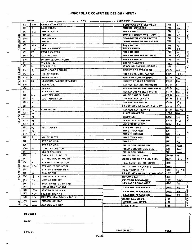
-- HOMOPOLAR COMPUTER DESIGN (INPUT)
MODEL
(2) KVA
(3) E
(4) Eph
IS) m" (So) fF-
161 p(7) RPM
< (8) I phn
(9) PF
(9o) K¢
(10)
(11) a
v (12) D
u< (13) _LI--•,_ 04) ._cO (15) b vF-< (16) KtF-•n (19) k
(20) B
(21)
(22) b o
(22) b 1
(22) b2
(22) b3F-O (22) b=J" (22) ho
O (22) h 1F-
< (22) h 2F-
Ln (22) h3
(22) t h,
(22) ht
(22) h w
(23) Q
(28)
(29)
(30) n$
(31) y
(32) c
(33)
z (34) m
Z (,34 a) N',t
(39)
(3s) a_I,-< (36) ,_ ,, 2I-.-
(37) h ,t
(38) h '.t
(420)
(40) "_'=k
(SO) X • o C
(51) _•
(59) g m in<
O (590) g mox
GENERATOR KVA
LINE VOLTS
PHASE VOLTS
PHASES
FREQUENCY
POLES
RPM
PHASE CURRENT
POWER FACTOR
ADJ, FACTOR
OPTIONAL LOAD POINT
STATOR I,D,
STATOR O.D,
GROSS CORE LENGTH
NO. OF DUCTS
WIDTH OF DUCT
STACKING FACTOR (STATOR)
WATTS/LB.
DENSITY
TYPE OF SLOT
SLOT OPENING
SLOT WIDTH TOP
SLOT WIDTH
SLOT DEPTH
NO. OF SLOTS
TYPE OF WDG.
TYPE OF COIL
CONDUCTORS/SLOT
SLOTS SPANNED
PARALLEL CIRCUITS
STRAND DIA. OR WIDTH
STRANDS/CONDUCTOR
STRANDS/CONDUCTOR
STATOR STRAND T'KNS
DIA. OF PIN
COIL EXT. STR. PORT
UNINS. STRD. HT,
DIST. BTWN. CL OF STD.
PHASE BELT/ANGLE
STATOR SLOT SKEW
STATOR TEMP °C
RES'TVY STA, COND, e 20 ° C
MINIMUM AIR GAP
MAXIMUM AIR GAP
EWO DESIGN NO(l)
FUND/MAX OF FIELD FLUX (71) C1
WINDING CONSTANT (72) Cw _--
POLE CONST. (73) Cp <F-
END EXTENSION ONE TURN (48) LE
I DEMAGNETIZATION FACTOR (741 Cm Ou
CROSS MAGNETIZING FACTOR (751 Cq
POLE WIDTH (76) bp
POLE LENGTH (1_,) ,_ p
POLE HEIGHT (76) I_ '-*U
POLE HEIGHT (EFFECTIVE) (761 h°pt_
POLE EMBRACE (77) _C
ROTOR DIAMETER (11ol .a.r _.-0
STACKING FACTOR (ROTOR) (16) K_ _,
WEIGHT OF ROTOR IRON (1571 (-)
POLE FACE LOSS FACTOR (187) (K 1 )
WIDTH OF SLOT OPENING (135) bbo
HEIGHT OF SLOT OPENING (135) hbo
DAMPER BAR DIA. OR WIDTH (136) ( )r,,
RECTANGULAR BAR THICKNESS (137) hbl,n
RECTANGULAR SLOT WIDTH (1351 bbl _zLU
NO. OF DAMPER BARS (1381 nb _-
DAMPER BAR LENGTH (139) 0 b
DAMPER BAR PITCH (140) _" b
RESISTIVITY OF DAMP. BAR • 20 ° (141) _D
DAMPER BAR TEMP oC (1421 Xo °C
SHAFT DIAMETER (780) D•hF-
SHAFT I.D. (7lie) d,h u.,(
SHAFT EXT. DIAMETER (780) d'=h -rv,a
LENGTH OF SHAFT (7Ba) < uhm
TYPE OF YOKE (78)
YOKE THICKNESS (78) ty ,,,
YOKE THICKNESS (78) _e vO
YOKE THICKNESS (78) t],r >"
YOKE I,D. (78) d_c
FIELD COIL INSIDE DIA. (78) dcoll
FIELD COIL OUTSIDE DIA. 7B) Dcoil
FIELD COIL WIDTH (78) bcoiI
NO. OF FIELD TURNS (146a) NF
MEAN LENGTH OF FLD. TURN (147) ,_ t+ !_
FLD. COND. DIA. OR WIDTH 1148) J _"
FLD, COND, T I'_(;:KNE_,_; (149)
FLD. TEMP IN o _; I1501 X _ oC.
RESISTIVITY OF _LD. COND. e20 ° [1511 '_s
klO LOAD SAT. [87)
,!tlCll. & WIM_ !1_I (F &W)ILEAKAGE PE RMEAI4CEPm _
............ 2;LEAKAGE PERMEANCE IIMal P5 <
LEAKAGE PERMEANCE. (85e) P6 ;Q:
I LEAKAGE PERMEANGE 86a) P7 L__
TOR LAM MTR'L [18)
i it,o-roe LAM. MTR'_ ,18)IYOKE MTR'L [IB_
DESIGNER
DATE
REV. I_
P-01
t
STATOR SLOT POL E
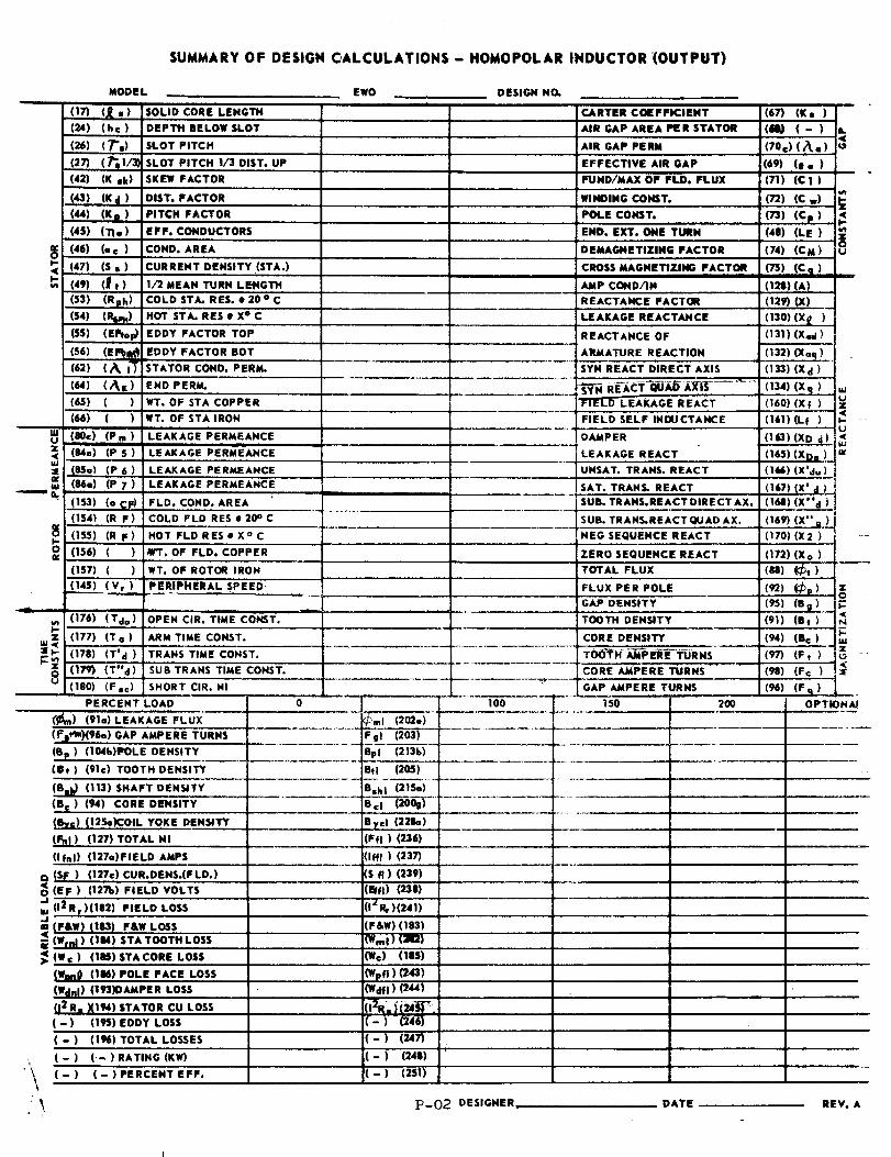
SUMMARY OF DESIGN CALCULATIONS- HOMOPOLAR INDUCTOR '(OUTPUT)
MODEL
(171 (_ ,) SOLID CORE LENGTH
(24) (he)
(26) 17%)
....(27) (P_ 1/21(42) (K sk)
(43) (X¢ )(44) (Ko)145) (11,)
(66) (oc)(67) (s,)(4_) (g t )
(53) (Rph)(54) 1,_)
(ss) (E_p)(56) (e_iie(62) (_. ,l"
(64) (A I )(65) ( )(66) ( )
(.ao.)(p.)z (S,lo) (ps)ul
_, (SSo) .(..p6 1_ (84°) (p 7)
(153) (o CF)
(1541 (R F)
ii,-)(RF)O 11561 ( )
(157) ( )
11__45) (vr)J
i
(1761 (Tdo)
._z (177) (To)][;" 11781 (T' d )
r-_ 117_1(T"d)(1801 (F.c)
PERCENT
\
EqO DESIGN NO,
DEPT11 BELOW SLOT
SLOT PITCH _AIR GAP PERM
SLOT PITCH I/3 DIST. UP
SKEW FACTOR
DIST. FACTOR
PITCH FACTOR
EFF. CONDUCTORS
COND. AREA
CURRENT DENSITY.(STA.)
1/2 MEAN TURN LEt4GTH
COLD STA. RES. • 20 ° C
HOT STA. RES • X ° C
EDDY FACTOR TOP
EDDY FACTOR BOT
STATOR COND. PERM.
END PERM.
WT. OF STA COPPER
WT. OF STA IRON
LEAKAGE PERMEANCE
LEAKAGE PERMEANCE
LEAKAGE PERMEANCE
LEAKAGE PERMEANCE
FLD. COND. AREA
COLD FLD RESe2_C
HOT FLD RESeX ° C
41rT. OF FLD. COPPER
WT. OF ROTOR IRON
P ER|P_tERAL SPEED;
OPEN CIR. TIME CONST.
ARM TIME CONST.
TRANS TIME CONST.
SUB TRAHS TIME CONST.
SHORT CIR. NI
LOAD 0
(91o) LEAKAGE FLUX
(.._.)(96o) GAP AMPERE TURNS
(Sp) (104b)P_OLE DENSITY
(IS,) (91c) TOOTH DENSITY
(B_ (113) SHAFT DENSITY
(B c ) (94) CORE DENSITY
_ByS) (12So)COIL YOKE DENSITY
(1_) (127) TOTAL NI
(If°l) (127a)FIELD AMPS
(SJ_ ) (127c) CUR.DENS.(FLD.)(EF) 11271>) FIELD VOLTS
112Rr1(1|21 FIELDLOSS
_- (eSw) 11.) e&w LOSS,4G (Wrnl) (IM) STA TOOTH LOSS
_4 (We) (lIB) STACORE LOSS
(Wahl) (106)POLE FACE LOSS
(W¢_11) (193)DAMPER LOSS
(I 2 R. )_194)STATOR CU LOSS
(-) (1,) EDDY LOSS
( - ) (194) TOTAL LOSSES
( - ) (-) RATING (KW)
....
( - ) ( - ) PERCENT EFF.
J .........
I ....
CARTER COEFFICIENT
AIR GAP AREA PER STATOR
EFFECTIVE AIR GAP
FUND/MAX OF FLD. FLUX
WINDING CONST,
POLE CONST.
END. EXT. ONE TURN
DEMAGNETIZING FACTOR
CROSS MAGNETIZING FACTOR
AMP COND/IN
REACTANCE FACTOR
LEAKAGE REACTANCE
REACTANCE OF
ARMATURE REACTION
SYN REACT DIRECT AXIS
FIELD LEAKAGE REACT
FIELD SELF INDUCTANCE
DAMPER
LEAKAGE REACT
UNSAT. TRANS. REACT
SAT. TRANS. REACT
' suB. TRAIlS.REACT DIRECT AX.
SUB. TRANS.REACT QUAD AX.
NEG SEQUENCE REACT
ZERO SEQUENCE REACT
! TOTAL FLUX
i FLUX PER POLE
GAP DENSITY
TOOTH DENSITY
CORE DENSITY
CORE AMPERE TURNS .....
"T ......... 10o
"_ml (202e)
egl E6pl (213b)
Btl (205)
Bsh I (215°)
a },el (228a)
(Ffl) (236)
(ira) (2371
(S fl ) (239)
(r_fl) (230)
(IzP.r)(241)
(F&W) (lS3)
_VmI ) (]121
(We) (185)
(Wpfl)(243)(waft) (244)
(_R_._(-_F_,(-) (246)
( - ) (247)
(-) (248)
(-) (251)
_/LGAP AMPERE TURNS150 200
B
(671 (K,)(i) (-)
170c)(_.) ?_(69) (I ° )
|
(71) (Cl)
(72) (C w)
(n) (Cr)(48) (LE)
O(74) (CM) u
(75) (Coi) .m(!_) (A)(129) 0()
(130) (X I )
113'1) (X,.I)
(132) (Xaq)
(1331 (Xd)
(134) (Xq) w
06o) (x_) u=11611 (Lf) _< .....
(1_3) (NO _))(16s)(xD.) =_(1M) (X'au)
11671 (X' d )
(1_) (X"d)
069) (x" _070) (X2)
(172) (Xo)
(u) (_,),.
(-) (S_l) p(911 (S,)
(94) (So)(97) (F,) _ .a--(98) (e,:)
(94) (Fq) _.
OPT
_-02 DESIGNER. DATE REV. A
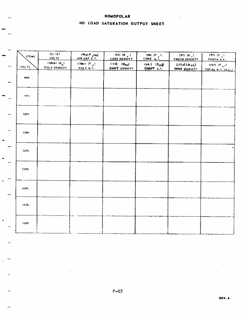
HOMOPOLAR
NO LOAD SATURATION OUTPUT SHEET
8O';,
90%
100%
i10%
120%
130%
140%
150%
160_
(3) (E)
VOLTS
(lOqb) (Bp)
POLE DENSITY
AIR GAP A.T.
(10_) (F)p
POLE A.T.
(94) (B ¢ )
CORE ,DENSITY
(._) (I_,**)_HAFT DEHSITY
(98) (F )c
CORE A.T.(91) (B t )
i TOOTH DENSITY
_I_G)I_.E' DENS.I TY
(97) (F )!
TOOTH A.T.
(127) (F nt )
TOTAL, A.T, (t4,L.)
P-03
REY. A
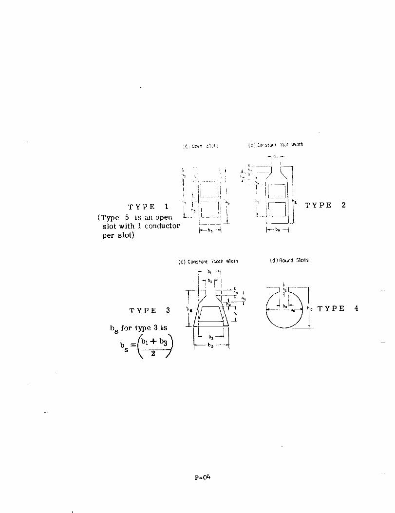
',_)Oren _'_ots
-_ ] i i
, ii! L-If...... _i i
TYPE I i _!! !i i(Type 5 is an open ..... :L__.J'_ ]
L..... !_Lslot with 1 conductor b-bs-qper slot)
(b) Consiont Slol Width
: i
L!_ ----3 [--I
_---- bs ---_
TYPE
TYPE 3
bs for type 3 is
bs 2
_C) Constont :_.._tl_Wi_th
f_ b, -'I
•,----- b3
(d) Round Slots
P-04
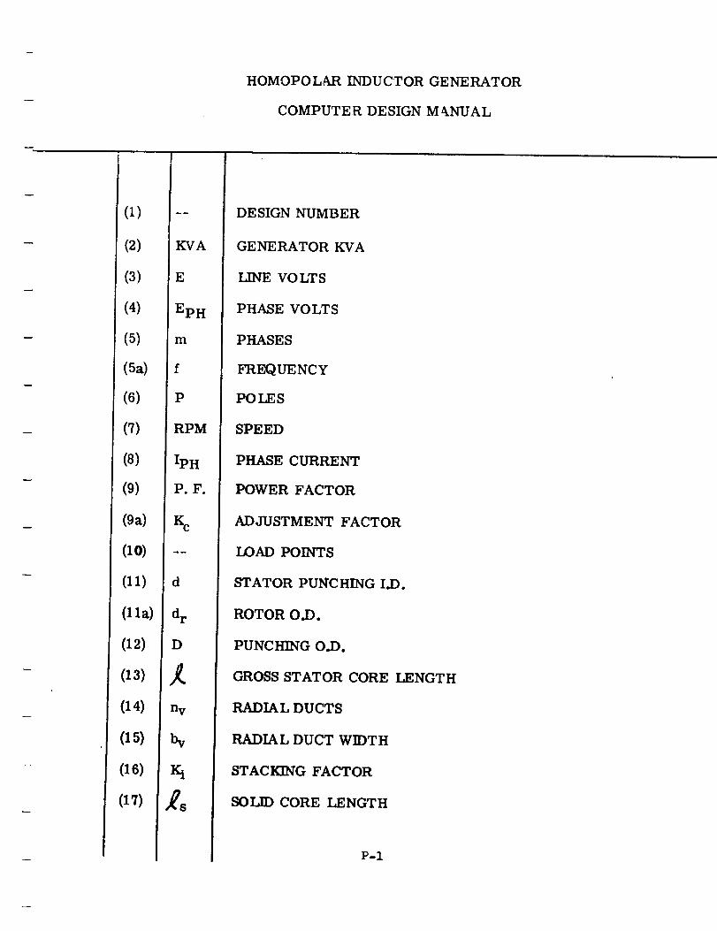
(1)
(2)
(3)
(4)
(5)
(Sa)
(6)
(7)
(8)
(9)
(9a)
(10)
(11)
(11a)
(12)
(13)
(14)
(15)
(16)
(17)
KVA
E
EpH
m
f
P
RPM
IpH
P.F.
d
dr
D
mm
Ill
n V
N
iqo,m
HOMOPOL_kR INDUCTOR GENERATOR
COMPUTER DESIGN M __NUAL
DESIGN NUMBER
GENERATOR KVA
LINE VOLTS
PHASE VOLTS
PHASES
FREQUENCY
POLES
SPEED
PHASE CURRENT
POWER FACTOR
ADJUSTMENT FACTOR
LOAD POINTS
STATOR PUNCHING I.D.
ROTOR O.D.
PUNCHING O.D.
GROSS STATOR CORE LENGTH
RADIAL DUCTS
RADIAL DUCT WIDTH
STACKING FACTOR
SOLID CORE LENGTH
P-I
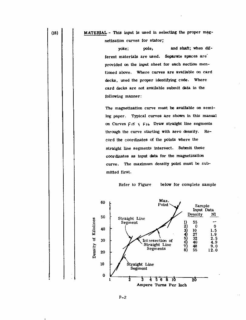
(18) MATERIAL- This input is used in selecting the proper m.ag-
netlzation curves for stator,
yoke; pole,
ferent materials are used.
and shaft; when dif-
Separate spaces are
provided on the input sheet for each section men-
tioned above. Where curves are available on card
decks, used the proper identifying code. Where
card decks are not available submit data in the
following manner:
The magnetization curve must be available on semi-
log paper. Typical curves are shown in this manual
on Curves F l_ _ F I_ Draw straight line segments
through the curve starting with zero density. Re-
cord the coordinates of the points where the
straight line segments intersect. Submit these
coordinates as input data for the magnetization
curve. The maximum density point must be sub-
mitted first.
Refer to Figure below for complete sample
cD
_J
6O
5O
40
30
2O
I0
0
Max.
Straight Line Point_
Segm4en_
Segmen_" St_raightLine 8
/ SegmeJrStraight Line
_ _ _"6 _ I_
Ampere Turns Per Inch
Density
1) 5503 I04 275 326 407 48
55
SampleInput Data
NI
01.51.92.54.99.012.0
,b
P-2
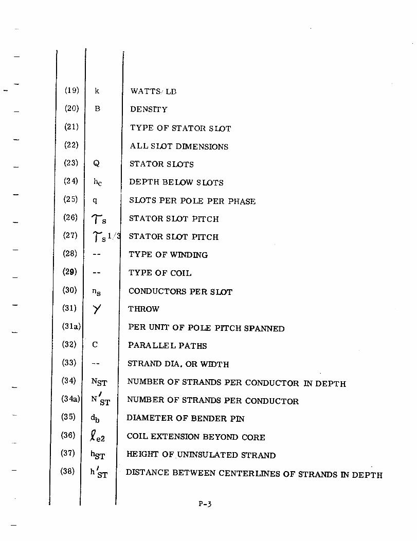
(19)
(20)
(21)
(22)
(23)
(24)
(25)
(26)
(27)
(28)
(29)
(30)
(31)
(31a)
(32)
(33)
(34)
(34a):
(35)
(36)
(37)
(38)
k
B
Q
hc
q
TS
_"s 1/_
m_
ns
Y
C
NST
NJsT
db
,re2
hsT
h'ST
WATTS/LB
DENSITY
TYPE OF STATOR SLOT
ALL SLOT DIMENSIONS
STATOR SLOTS
DEPTH BELOW SLOTS
SLOTS PER POLE PER PHASE
STATOR SLOT PITCH
STATOR SLOT PITCH
TYPE OF WINDING
TYPE OF COIL
CONDUCTORS PER SLOT
THROW
PER UNIT OF POLE PITCH SPANNED
PARALLE L PATHS
STRAND DIA. OR WIDTH
NUMBER OF STRANDS PER CONDUCTOR IN DEPTH
NUMBER OF STRANDS PER CONDUCTOR
DIAMETER OF BENDER PIN
COIL EXTENSION BEYOND CORE
HEIGHT OF UNINSULATED STRAND
DISTANCE BETWEEN CENTERLINES OF STRANDS IN DEPTH
P-3
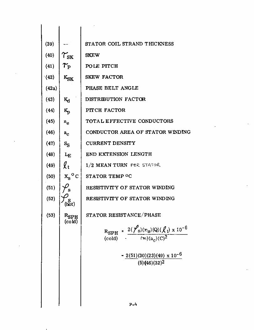
(39)
(40)
(41)
"(42)
(42a)
(43)
(44)
(45)
(46)
(47)
(48)
(49)
(50)
(51)
(52)
(53)
K
KSK
%
n e
ac
SS
LE
Xs°C
RSPH
(cold)
STATOR COIL STRAND THICKNESS
SKEW
POLE PITCH
SKEW FACTOR
PHASE BELT ANGLE
DISTRIBUTION FACTOR
PITCH FACTOR
TOTA L E FFECTIVE CONDUCTORS
CONDUCTOR AREA OF STATOR WINDING
CURRENT DENSITY
END EXTENSION LENGTH
1/2 MEAN TURN PEP..5T_TO_
STATOR TEMP oC
RESISTIVITY OF STATOR WINDING
RESISTIVITY OF STATOR WINDING
STATOR RESISTANCE/PHASE
RSPH = 2(fs)(_s)(q)(_t)
(cold) (_)(ac)(C)2
x I0 -6
•. 2(51)(30)(23)(49) x 10 -6
(5){46)(32)2
P-4
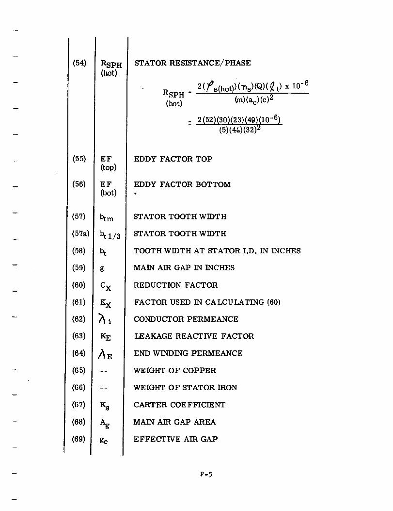
(54)
(55)
(56)
(57)
(57a)
(58)
(59)
(60)
(61)
(62)
(63)
(64)
(65)
(66)
(67)
(68)
(69)
RSPH
(hot)
EF
(top)
EF
(hot)
btm
btl/3
st
g
Cx
KX
Ks
Ks
%ge
STATOR RESISTANCE/PHASE
2(fs(hot))('ns)(Q)(_ t) x 10-6
RSp H -
(hot) (m)(ac)(c)2
_ 2(52)(30)(23)(49)(10 -6)
(5)(4_)(32)2
EDDY FACTOR TOP
EDDY FACTOR BOTTOM
STATOR TOOTH WIDTH
STATOR TOOTH WIDTH
TOOTH WIDTH AT STATOR I.D. IN INCHES
MAIN AIR GAP IN INCHES
REDUCTION FACTOR
FACTOR USED IN CALCULATING (60)
CONDUCTOR PERMEANCE
LEAKAGE REACTIVE FACTOR
END WINDING PERMEANCE
WEIGHT OF COPPER
WEIGHT OF STATOR IRON
CARTER COEFFICIENT
MAIN AIR GAP AREA
EFFECTIVE AIR GAP
P-5
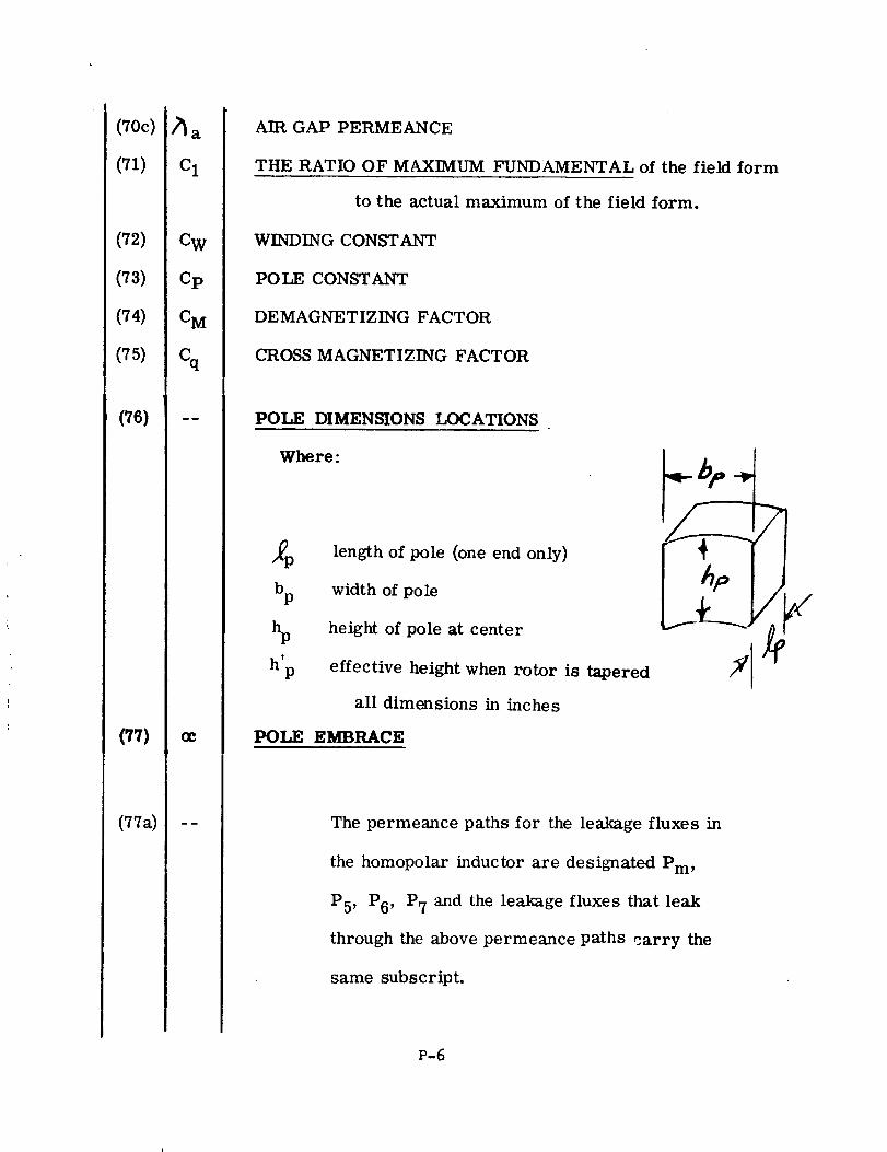
(70c)
(71)
(72)
(73)
(74)
(75)
(76)
(77)
(77a)
_a
C1
CW
Cp
C M
cq
OC
AIR GAP PERMEANCE
THE RATIO OF MAXIMUM FUNDAMENTAL of the field form
to the actual maximum of the field form.
WINDING CONSTANT
POLE CONSTANT
DEMAGNETIZING FACTOR
CROSS MAGNETIZING FACTOR
POLE DIMENSIONS LOCATIONS
Whe re:
bp
h'P
length of pole (one end only)
width of pole
height of pole at center
effective height when rotor is tapered
all dimensions in inches
POLE EMBRACE
The permeance paths for the leakage fluxes in
the homopolar inductor are designated Pm,
P5, P6' P7 and the leakage fluxes that leak
through the above permeance paths carry the
same subscript.
/
P-6
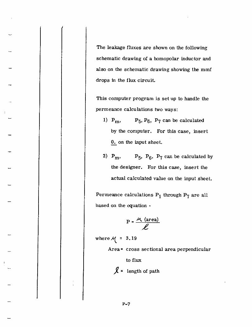
The leakage fluxes are shown on the following
schematic drawing of a homopolar inductor and
also on the schematic drawing showing the mmf
drops in the flux circuit.
This computer program is set up to handle the
permeance calculations two ways:
1) Pm, P5, P6, P7 can be calculated
by the computer. For this case, insert
0. on the input sheet.
2) Pm, P5, P6, P7 can be calculated by
the designer. For this case, insert the
actual calculated value on the input sheet.
Permeance calculations P1 through P7 are all
based on the equation -
p. _ (area)
where A_ =
Area --
3.19
cross sectional area perpendicular
to flux
length of path
P-7
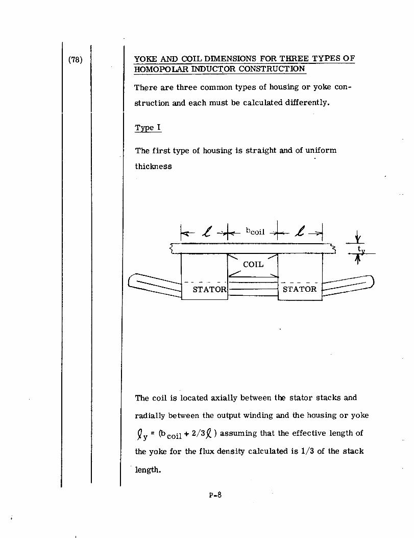
(78) YOKE AND COIL DIMENSIONS FOR THREE TYPES OF
HOMOPOLAR INDUCTOR CONSTRUCTION
There are three common types of housing or yoke con-
struction and each must be calculated differently.
Type I
The first type of housing is straight and of uniform
thickness
__z ._ _co__L__
I COIL 1
ity
STATOR_
The coil is located axially between the stator stacks and
radially between the output winding and the housing or yoke
_y = (bcoil + 2/3_ ) assuming that the effective length of
the yoke for the flux density calculated is 1/3 of the stack
length.
P-8
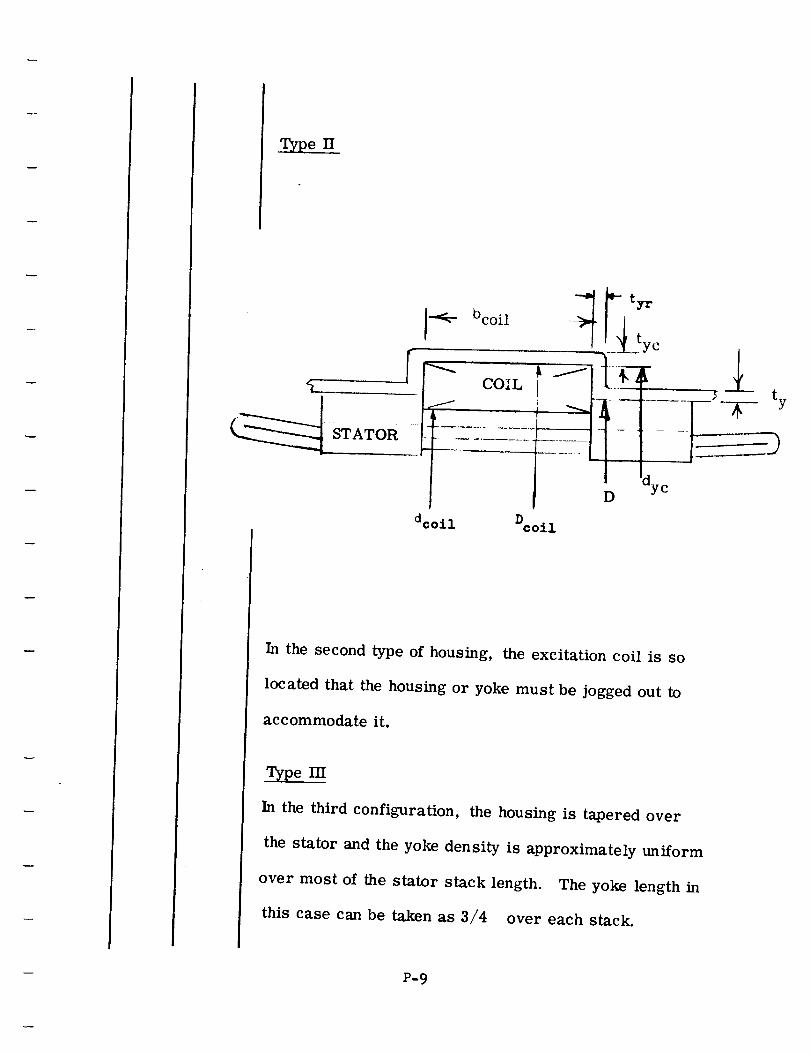
Type II
Oc°il _ F tyr
-----i D dyc
dcoil D coil
In the second type of housing, the excitation coil is so
located that the housing or yoke must be jogged out to
accommodate it.
Type III
In the third configuration, the housing is tapered over
the stator and the yoke density is approximately uniform
over most of the stator stack length. The yoke length in
this case can be taken as 3/4 over each stack.
P-9
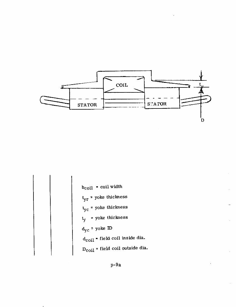
STATOR
r_
f
i
COIL
J
S?_ATOR
D
bcoil = coil width
ty r - yoke thickness
ty c = yoke thickness
ty = yoke thickness
dy c = yoke ID
dcoil = field coil inside dia.
Dcoil - field coil outside dia.
p-9a
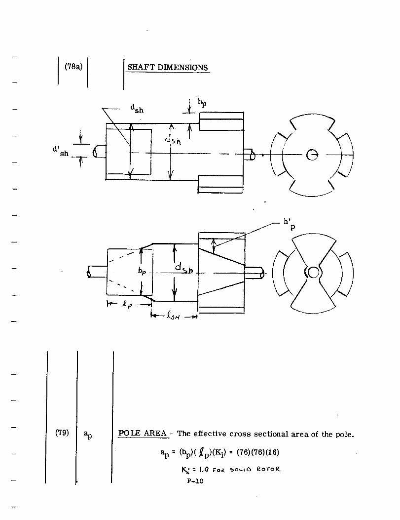
(78a) SHAFT DIMENSIONS
T
sh C
T
P
.I f
(79) .p POLE AREA - The effective cross sectional area of the pole.
ap = (bp)(_p)(Ki)-- (76)(76)(16)
K,:-- 1,0 r:o,_ _oL,,_ £oTo_
P-IO
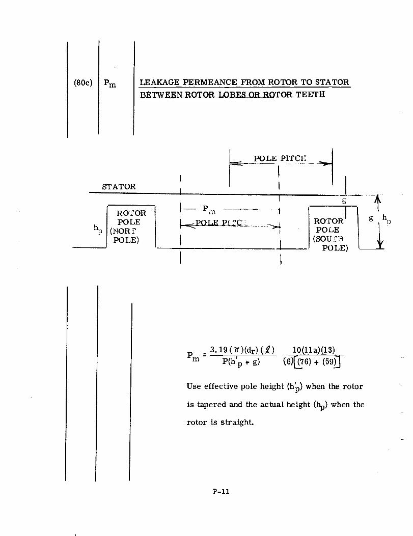
(80c) Pm LEAKAGE PERMEANCE FROM ROTOR TO STATOR
BETWEEN ROTOR LOBES OR ROTOR TEETH
STATOR
I RO'2OR
POLE
(_TORr:POLE)
POLE PITC_ ...._'_, II ' I I
i g
i-- Pm ............. i
I 1I t
ROTOR I
POLE
(SOU_'_.
POLE)
g h
___ P
3.19 ( vf )(dr) ( ,_ )p =
m P(h'p _- g)
10(11a)(13)
_6)_._6) + (59)"]
Use effective pole height (h_) when the rotor
is tapered and the actual height (hp) when the
rotor is straight.
P-If
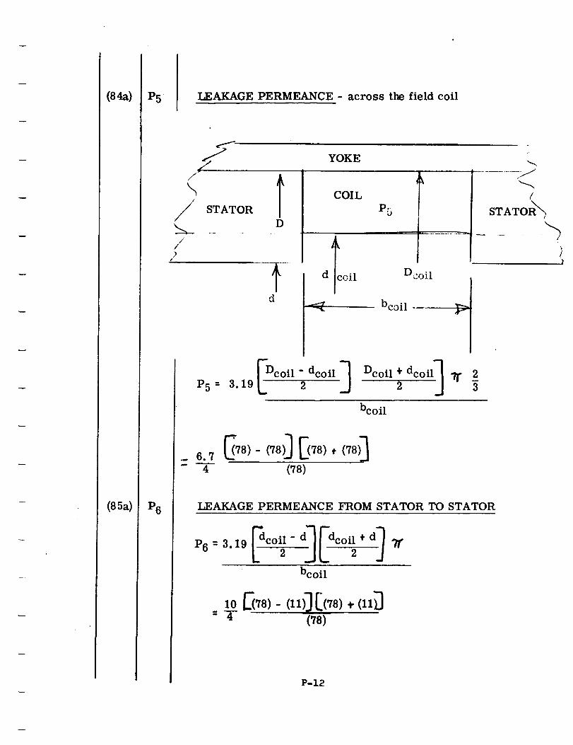
(8_)
(85a)
P5
P6
LEAKAGE PERMEANCE - across the field coil
S(-
J/
\//)
/
YOKE
STATOR
D
COIL
P5
Dcoil
P5 " _- Dc°il - dc°il ._ Dc°il + dc°il] "/r 23.19 -_ _ -
bcoil
- 4 ("/8)
LEAKAGE PERMEANCE FROM STATOR TO STATOR
P6 = 3.19
bcoil
,oE},_-("0[('_,(,,0: T (78)
P-12
(
STATOR_
l
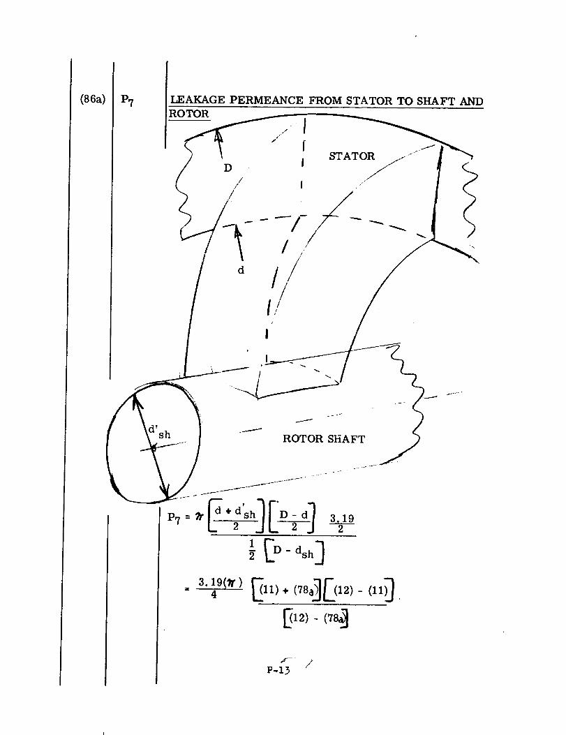
(86a) P7 LEAKAGE PERMEANCE FROM STATOR TO SHAFT AND
ROTOR
D
//
d
///
/
/
I
I
3.192
3.19(71") _] [(12)(II)_4 E 11) ÷ (78, - .
_12)- (78_
/P-13
(87)
(88)
(91)
(91a)
(91b)
Bt
em
AT
NO LOAD SATURATION CALCULATIONS - The next
calculations deal with no load saturation. When
the no load saturation data is required at various
voltages, insert 1. on input sheet for "No Load
Sat." The computer will then calculate the
complete no load saturation curve 80, 90, 100,
110, 120, 130, 140, 150 and 160% of rated volts.
When complete saturation data is not necessary,
insert 0. on input sheet and the cc nputer will
calculate data for rated voltage.
TOTAL FLUX in Kilolines
TOOTH DENSITY in Kilolines/in 2
Leakage flux from rotor to stator between/the rotor
lobes (poles or teeth).
0m .. (Pm) (Fg)x 10 -3- (80c)(96)(10 -3)
Area of the teeth of one stator at a point 1/3 the length
of the tooth out from the bore.
A T : Q kCs btl/3 : (23)(17)(57a)
P-14
(91c)
(92)
(94)
(94a)
(95)
(96)
B-r
0p
S c
A c )
Bg
Fg
The flux density in the stator teeth in Kilolines/in 2,
no-load rated voltage.
B T - ((ZlT) + (0m)(P)
(A T )
(88) • (91a)(6)(91b) '
at
FLUX PER POLE in Kilolines
The flux density in the core in Kilolines/in 2 at no-load
rated voltage.
Bc = (0p) , (Om) _ (92) * (91a)
(A c) (94a)
EFFECTIVE AREA OF THE CORE
P <6)
GAP DENSITY in Kilolines/in 2 - The maximum flux density
in the air gap.
(¢T) (88)Bg- o
//" (d) (,_) - _/'(11)(13)
AIR GAP AMPERE TURNS - The field ampere turns per pole
required to force the useful flux across the air
gap when operating at no load with rated voltage.
Fg = (Bg)(ge) 103 _ (95)(69) 1033.19 " 3.19
P-15
(96a)
(97)
(98)
(99)
Fg÷ m
FT
Fc
O7
Total air-gap ampere-turn drop across the single air-gap
at no-load, rated voltage.
(P)(0m)(g e) x 10 3Fg+m -- Fg +
3.19 (Ag)
- (96) + (6)(91a)(69) x 10 33.19 (68)
STATOR TOOTH AMPERE TURNS
FT - hs _NI/in at density(Bit);
- (22) FLook-up on stator magnetization curve given_
[in (18) at density (91c) J
STATOR CORE AMPERE TURNS
Fc :'_c: _I/in @B J
= 0'_)_NI/in @ (94)_
The flux leaking through leakage permeance path P7 at
no-load, rated volts. The leakage flux from the outer
end of the stator to the shaft and rotor.
0 7 :. 1:'7 ,.-('_Fg , m)_ x 10 -3" (86a)(9Ga) x 10-3
P-16
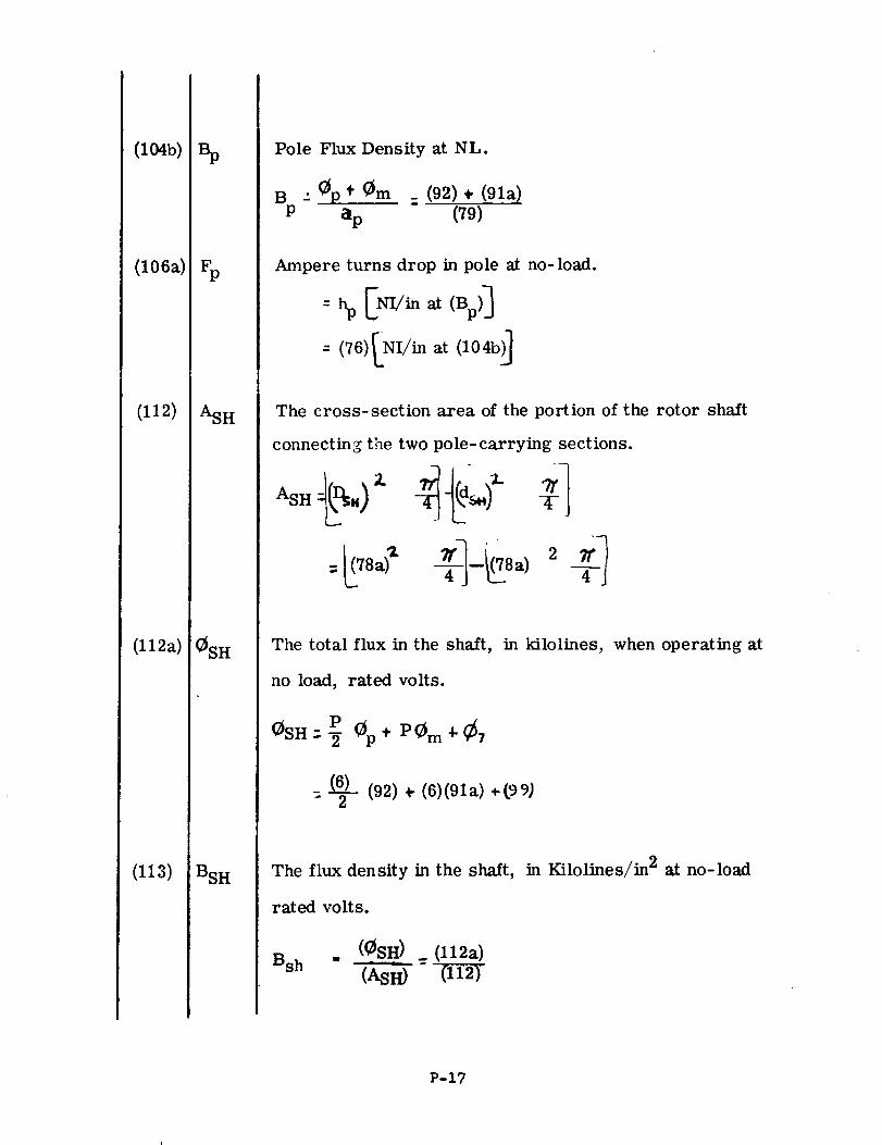
(I04b)
(106a)
(112)
(112 a)
(113)
ASH
OSH
BSH
Pole Flux Density at NL.
B : 0p* 0m _ (92) ÷ (91a)
P ap (79)
Ampere turns drop in pole at no-load.
The cross-section area of the portion of the rotor shaft
connecting the two pole- carrying sections.
The total flux in the shaft, in kilolines, when operating at
no load, rated volts.
POSHr.-_ _p+ P0 m4-¢7
(6) (92) + (6)(91a) +(99)=-_-
The flux density in the shaft, in Kilolines/in 2 at no-load
rated volts.
Bsh(_SH) _ (l12a)(ASH) "
P-17
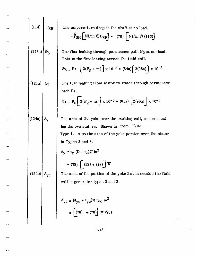
(114)
(l18a)
(121a)
(124a)
(124b)
FSH
_5
_6
Aye
The ampere-turn drop in the shaft at no load.
--_SH[NI/in@BsH _ - (78)[NI/in@(113)_
The flux leaking through permeance path P5 at no-load.
This is the flux leaking across the field coil.
_5:P5 L2(Fg.t m)]xl0-3= (84a)[2(96aOx10 -3
The flux leaking from stator to stator through permeance
path P6.
_6 : P6_(Fg. m)) x 10-3 = (85a) [2(96a)] x 10-3
The area of the yoke over the exciting coil, and connect-
ing the two stators. Shown in item 78 as
Type 1. Also the area of the yoke portion over the stator
in Types 2 and 3.
•, ty (D ÷ t,)ffin 2Ay J
The area of the portion of the yoke that is outside the field
coil in generator types 2 and 3.
Aye - (dye , tyc)y tyc in2
P-18
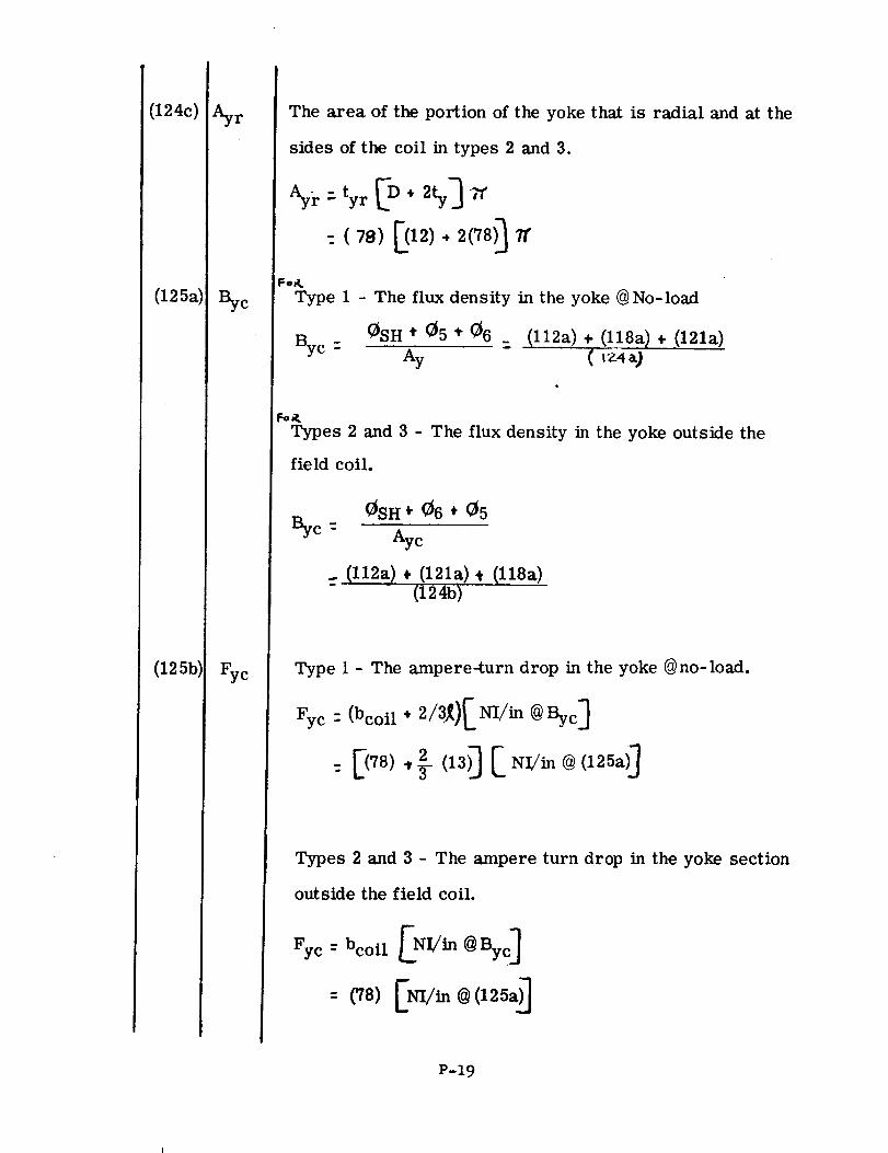
(124c)
(125a)
(125bl
Ayr
c
Fyc
The area of the portion of the yoke that is radial and at the
sides of the coil in types 2 and 3.
%/.:. ty r [D÷ 2ty]
- (78) [(12). 2(78)_
l:=o&
Type 1 - The flux density in the yoke @ No-load
0SH .i" 05 ,i- 06 _e
(l12a) ÷,(l18a) + _(121a)( r_'4_)
Types 2 and 3 - Tile flux density in the yoke outside the
field coil.
0SH + 06 + 05Byc - Aye
... (l12a) + (1218)+ (l18a)- (124b)
Type 1 - The ampere-turn drop in the yoke @no-load.
Fyc: (bcoil + 2/3_)[ m/in @ Byc]
Types 2 and 3 - The ampere turn drop in the yoke section
outside the field coil.
Fyc= bcoil [NI,/in @Bye]
P-19
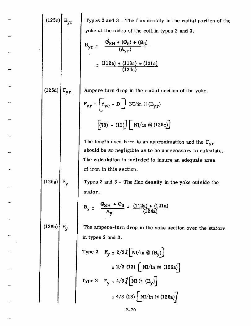
(125c)
(125d)
(126a)
(126b)
Byr
Fyr
Types 2 and 3 - The flux density in the radial portion of the
yoke at the sides of the coil in types 2 and 3.
0SH ÷ (05) + (06)By r -
(Ayr)
_ (l12a) + (llSa) + (121a)(t24c)
Ampere turn drop in the radial section of the yoke.
Fyr= _dyc-D _ NI/in@(By r)
The length used here is an approximation and the Fy r
should be so negligible as to be unnecessary to calculate.
The calculation is included to insure an adequate area
of iron in this section.
Types 2 and 3 - The flux density in the yoke outside the
stator.
By_ CSH * ¢6 = (112a}, 021a)Ay (124a)
The ampere-turn drop in the yoke section over the stators
in types 2 and 3.
Type2 Fy-2/31[[NI/'in @ (By)_]
= 2/3 (13) _ Nl/in @ (126a_
P-20
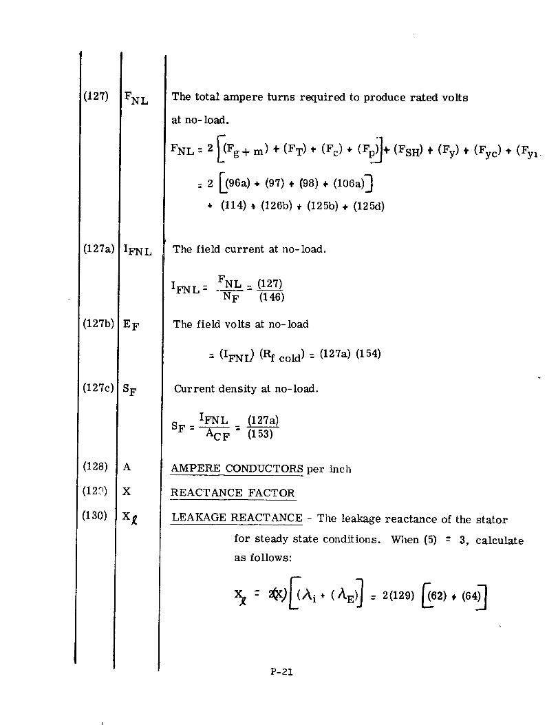
027)
(i 27a)
(127b)
(127c)
(128)
(12_)
(130)
FN L
IFNL
EF
S F
A
X
x_
The total ampere turns required to produce rated volts
at no- load.
FNL = 2 _Fg+
:2
÷
1
m) ÷ (FT) ¢ (Fc) + (Fp_÷(FsH)
_96a). (97)+ (98)+ (I06a)]
(114) _ (126b) + (125b) + (125d)
÷ (Fy),(Fyc), (Fy,_
The field current at no-load.
IFN L- FNL_ (127)N F (146)
The field volts at no-load
: (IFNI) (Rf cold ) : (127a) (154)
Current density at no-load.
IFNL (127a)
SF: _-F:" (15-_
AMPERE CONDUCTORS per inch
REACTANCE FACTOR
LEAKAGE REACTANCE - The leakage reactance of the stator
for steady state conditions. When (5) - 3, calculate
as follows:
X_- 2_)_/_i* (/_E)_- 2(129)_62),(64)_
P-21
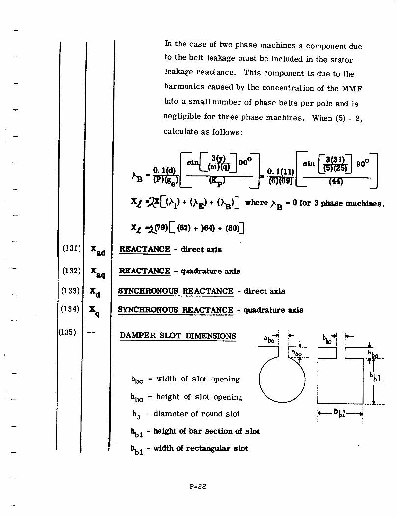
(131)
(132)
(133)
(134)
(135)
x_
Xd
%
mm
In the case of two phase machines a component due
to the belt leakage must be included in the stator
leakage reactance. This component is due to the
harmonics caused by the concentration of the MMF
into a small number of phase belts per pole and is
negligible for three phase machines. When (5) - 2,
calculate as follows:
0. l(d) / U / 0. 1(11)
x__E(h)+ (_.)+(%)] -_,_ ;_B
xL -_pg)E (e_)+ )e41+ (eo)]
REACTANCE - direct
= 0 for 3 phase machines.
REACTANCE - quadrature axis
SYNCHRONOUS REACTANCE - direct axis
SYNCHRONOUS REACTANCE - quadrature axis
DAMPER SLOT DIMENSIONS
bbo - width of slot opening
hbo - height of slot opening
go -diameter of round slot
hbl - height of bar section of slot
bbl - width of rect_gular slot
i
L ;t'-hbl
°-._o..
!
P-22
(136)
(137)
(138)
(139)
(14o)
(141)
(142)
(143)
(144)
(145)
(146)
(147)
(148)
(149)
hbl
nb
Jb
'7"b
PD
XD°C
acd
Vr
NF
j2tF
DAMPER BAR DIA OR WIDTH in inches
DAMPER BAR THICKNESS in inches - Damper bar thickness
considered equal to damper bar slot height (hb) per
Item (135). Set this item = 0 for round bar.
NUMBER OF DAMPER BAllS PER POLE
DAMPER BAR LENGTH in inches
DAMPER BAR PITCH in inches
RESISTIVITY of damper bar @ 20°C in ohm-inches
DAMPER BAR TEMP °C- Input temp at which damper losse,,
are to be calculated.
RESISTIVITY of damper bar @ XD°C
CONDUCTOR AREA OF DAMPER BAR - Calculate same as
stator conductor area
PERIPHERAL SPEED - The velocity of the rotor surface in
feet per minute
NUMBER OF FIELD TURNS PER COIL
MEAN LENGTH OF FIELD TURN
FIELD CONDUCTOR DIA OR WIDTH in inches
FIELD CONDUCTOR THICKNESS in inches - Set this item :
for round conductor.
P-23
(15o)
(151)
(152)
(153)
(]54)
(]55)
(156)
(157)
Xf°C
(_h_ot)
acf
Rf(co] 1)
Rf(hot
FIELD TEMP IN °C - Input temp at which full load field
los_ is to be calculated.
RESISTIVITY of field conductor @ 20°C in micro ohm-inches.
Refer to table given in Item (51) for conversion fac-
tors.
RESISTIVITY of field conductor at Xf°C
CONDUCTOR AREA OF FIELD WINDING - Calculate same
as stator conductor area
COLD FIELD RESISTANCE @ 20°C per coil
Rf(cold) = (.pf)(NF)(._tf) x 10 -6
(acf)= (151)(146)(147a) x 10 -6
(153)
HOT FIELD RESISTANCE - Calculated at Xf°C
Rf(hot) = (_fhot) (Nf)(]_tf) x 10 -6(acf)
_ (152)(146)(147a) x 10-'
(153)
WEIGHT OF FIELD COPPER in Ibs.
#'s of copper = .321 (Nf)(_tf)(acf)
= . 321 (146)(147a)(153)
WEIGHT OF ROTOR IRON - Because of the large number of
different pole shapes, one standard formula cannot
be used for calculating rotor iron weight. There-
fore, the computer will not calculate rotor iron
weight.
P-24
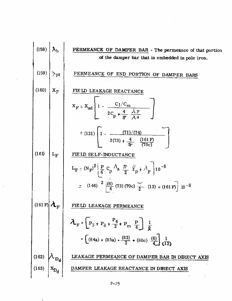
(158)
I
(159)
(160)
(161)
(161F)
(162)
(163)
_b
_pt
X F
L F
PERMEANCE OF DAMPER BAR - The permeance of that portion
of the damper bar that is embedded in pole iron.
PERMEANCE OF END PORTION OF DAMPER BARS
FIE LD LEAKAGE REACTANCE
XF : Xad I - CI/C---m2C_ ,. 4 _F
-" (131)
I (71)/(74)2(73), 4 (161F)
FIE LD SE LF-INDUCTANCE
LF- (NF)2_ CpAa 7"f _P_'/]F_I0-82
- (146) 2 (73)(70c)-_-- (13) -t-(161F)_ l0 -8C_
FIELD LEAKAGE PERMEANCE
_p P4 ____ 1J)LF = 5 * P6 # _ + Pm _-
= [(84_) ÷ (85_). (83__/).(8oc) (6)_[ 1
2 --4-.-] t]--3}
LEAKAGE PERMEANCE OF DAMPER BAR IN DIRECT AXIS
DAMPER LEAKAGE REACTANCE IN DIRECT AXIS
P-25
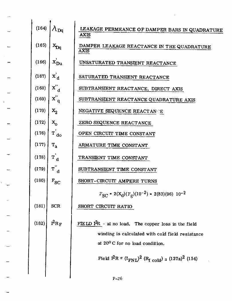
(164)
(165)
(166)
(167)
(168)
(169)
(170)
(172)
(176)
(177)
(178)
(179)
(180)
(181)
(182)
/_Dq
XDq
XDu
!
X d
Xd
tt
Xq
X2
Xo?
T do
W a
V
Td
tf
Td
FSC
SCR
I2RF
LEAKAGE PERMEANCE OF DAMPER BARS IN QUADRATUREAXIS
DAMPER LEAKAGE REACTANCE IN THE QUADRATUREAXIS
UNSATURATED TRANSIENT REACTANCE
SATURATED TRANSIENT REACTANCE
SUBTRANSIENT REACTANCE, DIRECT AXIS
SUBTRANSIENT REACTANCE QUADRATURE AXIS
NEGATIVE SEQUENCE REACTAN _?E
ZERO SEQUENCE REACTANCE
OPEN CIRCUIT TIME CONSTANT
ARMATURE TIME CONSTANT
TRANSIENT TIME CONSTANT
SUBTRANSIENT TIME CONSTANT
SHORT-CIRCUIT AMPERE TURNS
= 2(Xd)(Fg)(10-2 ) - 2(83)(96)FSC
SHORT CIRCUIT RATIO
10-2
FIELD I2R - at no load. The copper loss in the field
winding is calculated with cold field resistance
at 20 ° C for no load condition.
Field I2R --" (IFNL) 2 (Rf cold) "- (127a) 2 (154)
P-26
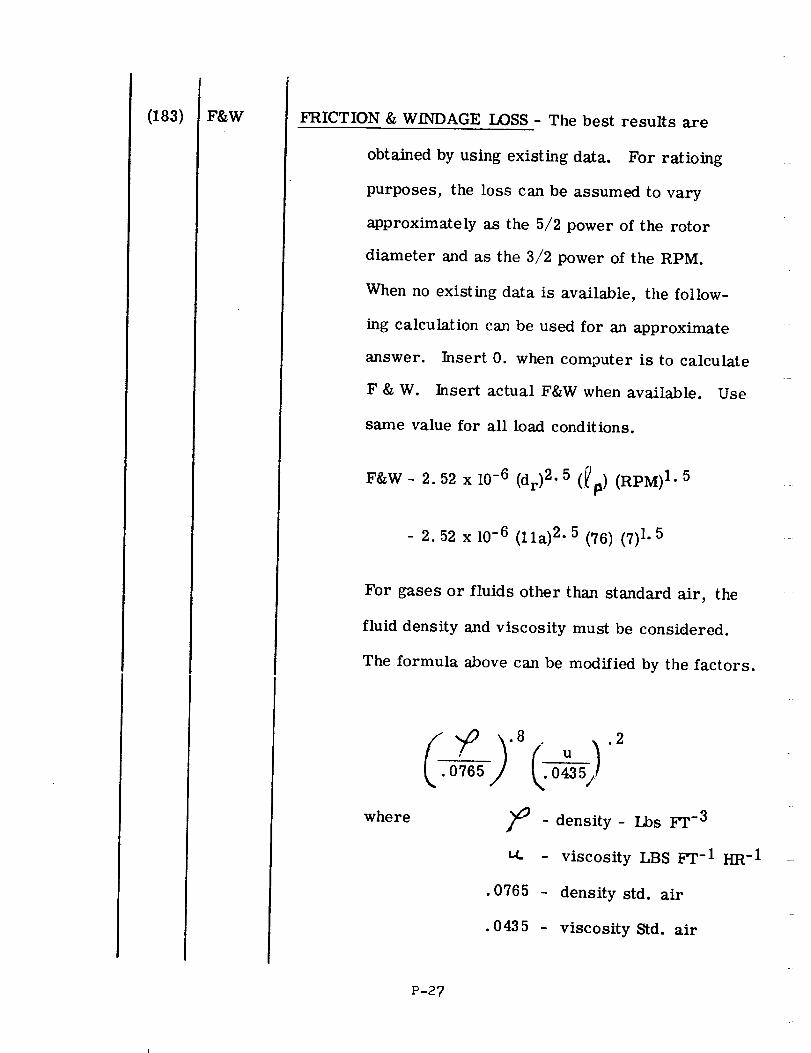
(183) F&W FRICTION & WINDAGE LOSS - The best results are
obtained by using existing data. For ratioing
purposes, the loss can be assumed to vary
approximately as the 5/2 power of the rotor
diameter and as the 3/2 power of the RPM.
When no existing data is available, the follow-
ing calculation can be used for an approximate
answer. Insert 0. when computer is to calculate
F & W. Insert actual F&W when available. Use
same value for all load conditions•
F&W- 2.52 x 10⁻⁶ (dr)2.5 (_p)(RPM)I
- 2.52 x 10 -6 (lla) 2- 5 (76) (7) 1. 5
.5
For gases or fluids other than standard air, the
fluid density and viscosity must be considered.
The formula above can be modified by the factors.
where
( )0765 0435
Fr-3- density- Lbs
_.. - viscosity LBS _l'- 1 I-IR- 1
• 0765 - density std. air
• 0435 - viscosity Std. air
P-27
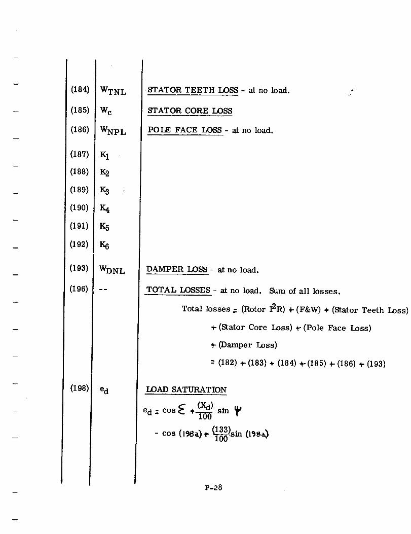
(184)
(185)
(186)
(187)
(188)
(189)
(190)
(191)
(192)
(193)
(196)
(198)
WTNL
Wc
WNPL
K1
K2
K3 :
K4
K5
K6
WDNL
e d
STATOR TEETH LOSS - at no load.
STATOR CORE LOSS
POLE FACE LOSS- at no load.
DAMPER LOSS - at no load.
TOTAL LOSSES - at no load. Sum of all losses.
Total losses .: (Rotor I2R) +-(F&W) + (Stator Teeth Loss)
_-(Stator Core Loss),-(Pole Face Loss)
_- (Damper LOss)
-" (182) ÷ (183) ÷ (184) _- (185) +- (186) _- (193)
LOAD SATURATION
e d :. cos_ ÷(-_0 ) sin
cos (l_). %o3o3)Sin0_)
P-28
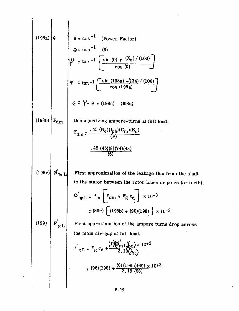
(198a)
(198b)
(198c)
(199)
9
Fdm
t
FgL
-i@ ,-- cos
-il_ - COS
J :tan -1
(Power Factor)
(9)
__sin_(°) ÷(xq)/(l°°)-_cos(o)
_v :tan-l_sin(198a)+(]34)/(lO0)lcos (198a)
- _/- 0. = (198a) - (198a)
Demagnetizing ampere-turns at full load.
Fd m _- .45 (Ne)(_l)_)(Cm)(Kd)
• 45 (45)(8)(74)(43)
(6)
First approximation of the leakage flux from the shaft
to the stator between the rotor lobes or poles (or teeth)•
mEF mx,0 =-(80e> E(198b) ÷ (96)(198)_ x 10-3
First approximation of the ampere turns drop across
the main air-gap at full load.
I
F'g L Fg ed ÷(P)_Om L)_e) x10*3: 3.19(._)
(6) (198c)(69) x 10+3.; (96)(198) 4- - 3.19=(68)
P-29
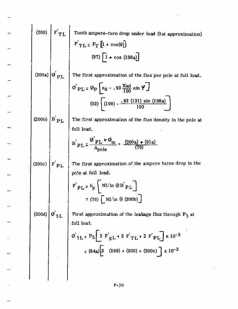
(200)
(200a)
(200b)
(200c)
(200d)
_r, clot
!
BpL
FpL
Tooth ampere-turn drop under load (lst approximation)
F TL : FT ÷ cos(0
(97) _ • cos (198a)_
The first approximation of the flux per pole at full load.
0'pL = 0p [ed - .93 xadT0_6sin _¢]
(92) _198)-'93(131)sin(198a)_100
The first approximation of the flux density in the pole at
full load.
' 0'PL ÷ 0m = (200a) _- (91a)
B PL = Apol e (79)
The first approximation of the ampere turns drop in the
pole at full load.
PL= N _/in @B'pL
--(76)[Nij'm (2oob)]
First approximation of the leakage flux through P5 at
full loa::l,
E2F' ' L]O'SL = P5 gL't 2 F TL * 2 F'p x 10 -3
: (84a)_ (199)., (200), (200c)J x 10 -3
P-30
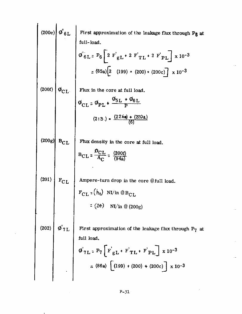
(200e)
(2000
(2OOg)
(2Ol)
(202)
BCL
FC L
First approximation of the leakage flux through P8 at
full- load.
_6L: P6 FgL
:. (85a)
• 2 F'TL + 2 F'pL ] x 10 -3
(199) * (200) * (200c)_ x 10 -3
Flux in the core at full load.
_5L ÷ _6L
(_CL - _PL ÷ p
Flux density in the core at full load.
OCL
BCL=--_C :
Ampere-turn drop in the core @full load.
FCL :Chc_ NI./in @BcL
" (Z_-) N-I/in @ (200g)
First approximation of the leakage flux through P7 at
full load.
_'7L:P7[ F' ' F'PL _gL* FTL, xl0 -3
=. (86a) _(199) * (200) + (200c)_ x 10-3
P-31
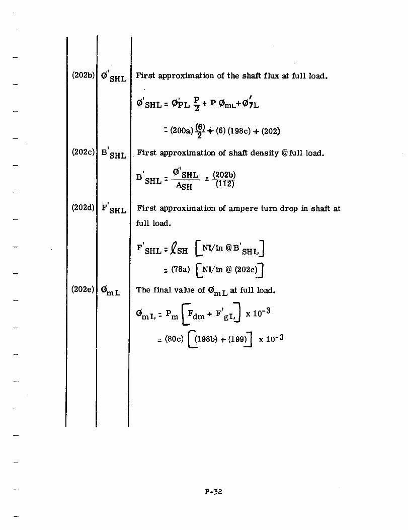
(202b)
(202c)
(202d)
(202e)
(_'SHL
!
B SHL
T
F SHL
First approximation of the shaft flux at full load.
SHL _- _PL ÷ P _mt.+{_TL
- (200a) (_ + (6) (198c) + (202)
First approximation of shaft density @ full load.
' (_'SHL _B SHL- AS H
First approximation of ampere turn drop in shaft at
full load.
F!
SHL - _SH ENI/in @ B'SHLJ
: (78a) _NI/in @ (202c)_
The final value of (_m L at full load.
@mL: Pm _Fdm + F'gL_ xl0 -3
:. (80c) _198b) + (199)_ x 10 -3
P-32
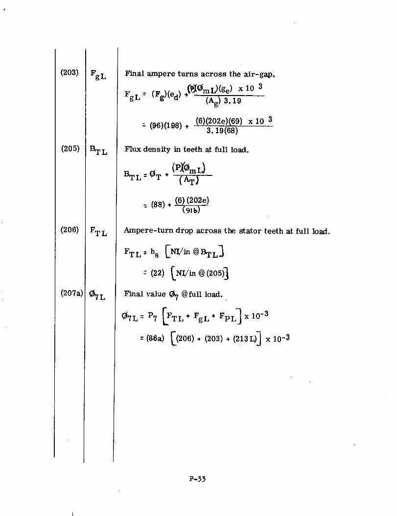
(2o3)
(2o5)
(206)
(2O7a)
FgL
BTL
FTL
_7L
Final ampere turns across the air-gap.
Fg L : (Fg)(ed) ÷(_0mi.,)(ge) x 10 3(Ag) 3.19
(6)(202e)(69) x 10 3- (96)(198) ,
3.19(68)
Flux density in teeth at full load.
BT L = _T ÷ (AT_
= (88) ÷ (6)(202e)
Ampere-turn drop across the stator teeth at full load.
FTL= hs [NI/in @BTL]
Final value _7 @ full load.
_= _ [_L"F_L"F_L_X_0_: (86a) [(206), (203) • (213L)] x 10 -3
P-33
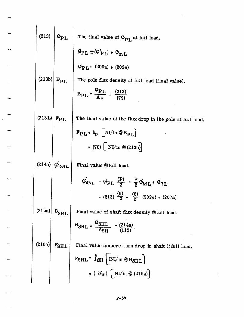
(213)
(213b)
(213L)
(214a)
(215a)
(216a)
Bp L
FpL
BSHL
FSHL
The final value of @PL at full load.
_$PL m(e'Pi) + _mL
(_pL = (200a) + (202e)
The pole flux density at full load (final value).
0PL_ (213)
BpL" Ap (79)
The final value of the flux drop in the pole at full load.
: (76)[ NI/
Final value @full load.
P
" (213) (62) + (26-(26-/))(202e), (207a)
Final value of shaft flux density @full load.
BSH L; 0SHL :(214a)
ASH (112)
Final value ampere-turn drop in shaft @full load.
P-34
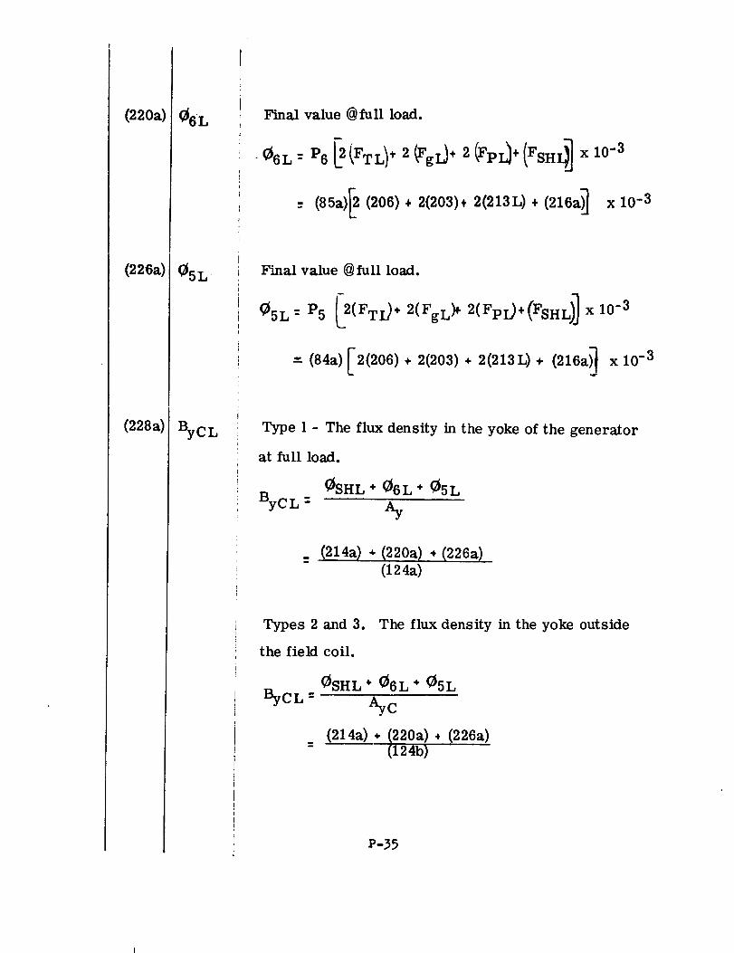
(220a)
(226a)
(228a)
_6L
ByCL
Final value @full load.
- (85a)_ (206)+ 2(203)+ 2(213L) + (216a)] x 10 -3
Final value @ full load.
"" (84a) r2(206) ÷ 2(203) ÷ 2(213L) ÷ (216a_ x 10 -3L. -j
Type 1 - The flux density in the yoke of the generator
at full load.
_SHL * _6L * O5LBFCL : Ay
_ (214a) * (220a) • (226a)
(124a)
Types 2 and 3. The flux density in the yoke outside
the field coil.
ByCL =_SHL* 06L ÷ 05L
AyC
(214a) • (220a)(124b)
• (226a)
P-35
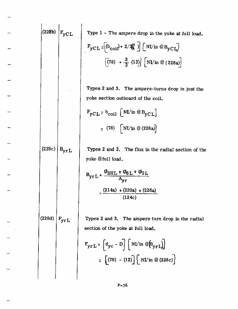
(228b)
(228c)
(228d)
FyCL
ByrL
FyrL
Type 1 - The ampere drop in the yoke at full load.
Types 2 and 3. The ampere-turns drop in just the
yoke section outboard of the coil.
FyC L -bcoil _NI/in @ By C L]
: (78) _NI/in @ (228a)_
Types 2 and 3. The flux in the radial section of the
yoke @full load.
ByrL =_SHL t _6L 4. _5L
Ayr
(214a) ÷ (220a) ÷ (226a)
(124c)
Types 2 and 3. The ampere turn drop in the radial
section of the yoke at full load.
P-36
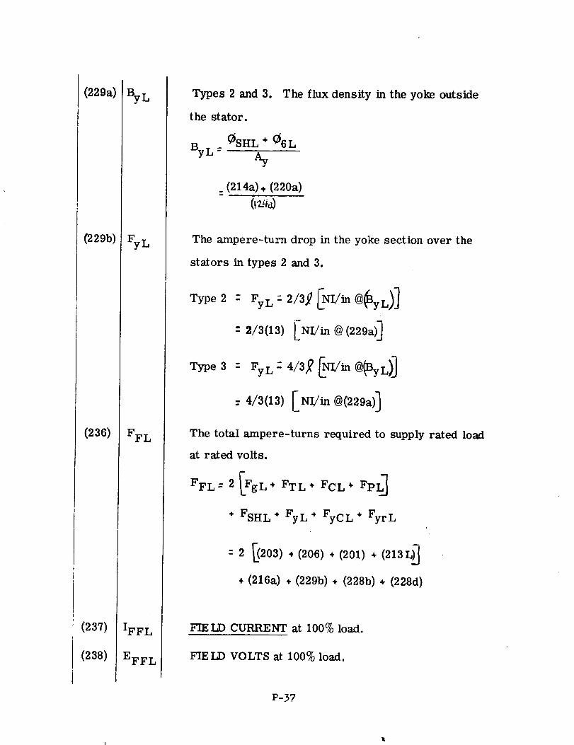
(229a)
(229b)
(236)
(237)
(238)
ByL
FyL
FFL
IFFL
EFFL
Types 2 and 3. The flux density in the yoke outside
the stator.
By L -0SHL ÷ _6L
%
_ (214a). (220a)m
The ampere-turn drop in the yoke section over the
stators in types 2 and 3.
Type2 - FyL: 2/3_ _NL/in@_yL)J
: 2/3(13) [NL/in @ (229a)]
Type3 : Fy L - 4/3_ 0 _rl/in @_3yL) ]
: 4/3(13) ENI/in @(229a)]
The total ampere-turns required to supply rated load
at ra_ed volts.
FFL--2 [FgL. FTL" FCL. FpL_
÷ FSHL ÷ FyL* FyCL + FyrL
: 2 203) • (206) + (201) ÷ (213
÷ (216a) ÷ (229b) ÷ (228b) ÷ (228d)
FIELD CURRENT at 100% load.
FIE LD VOLTS at 100% load.
P-37
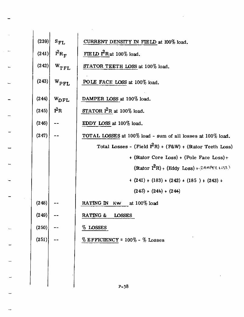
(239)
(241)
(242)
(243)
(244)
(245)
(247)
(248)
(249)
(25o),
(251)
SFL
I2RF
WTFL
WpFL
WDFL
I2R
CURRENT DENSITYIN FIELD at 100%load.
FIELD 12Rat 100%load.
STATORTEETHLOSSat 100%load.
POLE FACE LOSS at 100% load.
RATING IN KW
RATING &
DAMPER LOSS at 100% load.
STATOR I2R at 100% load.
EDDY LOSS at 100% load.
TOTAL LOSSES at 100% load - sum of all losses at 100% load.
Total Losses - (Field I2R) ÷ (F&W) + (Stator Teeth Loss)
÷ (Stator Core Loss)+ (Pole Face Loss)+
(Stator I2R), (Eddy Loss) r,pA_f_o.. L..:.'_'s
(241) + (183) + (242) + (185) + (243)
(245) _- (24b) + (244.)
at 100% load
LOSSES
% LOSSES
% EFFICIENCY-- 100%- % Losses
P-38

r
|
SE CTION R
!
!
|!!
!
iU
iN
!
N!
DESIGN MANUAL FOR PERMANENT-M&GNET
SALIENT-POLE, A-C GENERATORS
WSECTION R
all
_TF
!
w
|
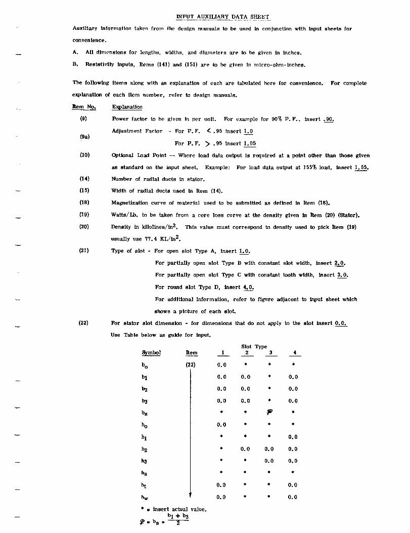
INPUT AUXILIARY DATA SHEET
Auxiliary information taken from the design manual_ to be used in conjunction with input sheets for
convenience.
A. All dimensions for lengths, widths, and diameters are to be given in inches.
B. Resistivity. inputs, Items (141) and (151) are to be given in micro-ohm-inches.
The following items along with an explanation of each are tabulated here for convenience.
explanation of each item number, refer to design manuals.
Item No.
(9)
(9a)
(10)
(14)
(15)
(18)
(19)
(20)
(21)
(22)
For complete
For stator
Use Table
Explanation
Power factor to be given in per unit. For example for 90% P.F., insert .90.
Adjustment Factor - For P.F. _ .95 insert 1.0
For P.F. _> .95 insert 1.05
Optional Load Point -- Where load data output is required at a point other than those given
a_ standard on the input sheet. Example: For load data output at 155% load, insert 1.55.
Number of radial duets in stater.
Width of radial ducts used In Item (14).
Magnetization curve of material used to be submitted as defined in Item (18).
Watts/Lb. to be taken from a core loss curve at the density given in Item (20) (Stator).
Density in kilolines/in 2. This value must correspond to density used to pick Item (19)
usually use 77.4 KL/in 2.
Type of slot - For open slot Type A, insert 1.0.
For partially open slot Type B with constant slot width, insert 2.0.
For partially open slot Type C with constant tooth width, insert 3.0.
For round slot Type D, insert 4.0.
For additional information, refer to figure adjacent to input sheet which
shows a picture of each slot.
slot dimension - for dimensions that do not apply to the slot insert 0.0.
below an guide for input.
_mbol Item
bo (22)
bl
b2
b3
bs
ho
hl
h2
ha
hs
ht
hw
* • insert actual value.b 1% b 3
_=bs= 2
Slot Type1 2 3 4
0.0 * * *
0.0 0.0 * 0.0
0.0 0.0 * 0.0
0.0 0.0 * 0.0
0.0 * * *
• * * 0.0
• 0.0 0.0 0.0
• * 0.0 0.0
0.0 * * 0.0
0.0 * * 0.0
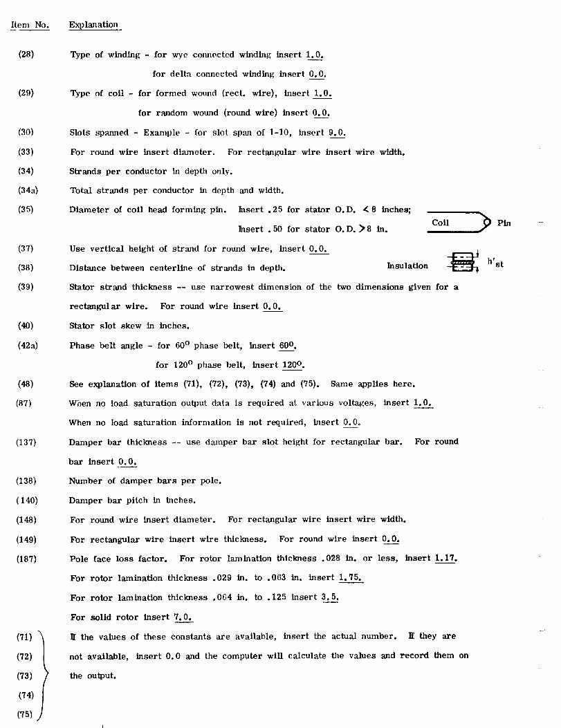
Item No. Explanation
(28)
(29)
(30)
(33)
(34)
(343)
(35)
(37)
(38)
(39)
(40)
(428)
(48)
(87)
(137)
(138)
(140)
(148)
(149)
(187)
(71)
(72)
(73)
(74)
(75)
Type of winding - for wye commcted winding insert 1.0.
for delta connected winding insert 0.0.
Type of coil - for formed wound (rect. wire), insert 1.0.
for random wound (round wire) insert 0.0.
Slots spammd - Example - for slot span of 1-10, insert 9.0.
For round wire insert diameter. For rectangular wire insert wire width.
Strands per conductor in depth only.
Total strands per conductor in depth and width.
Diameter of coil head forming pin. Insert . 25 for stator O.D. _ 8 inches; i
Insert .50 for stator O.D. >8 in. Coil 2Pin
Use vertical height of strand for round wire, insert 0.0.
Distance between eenterline of strands in depth. Insulation -_ h'st
Stator strand thickness -- use narrowest dimension of the two dimensions given for a
rectangular wire. For round wire insert 0.0.
Stator slot skew in inches.
Phase belt angle - for 60 ° phase belt, insert 60 °.
for 120 ° phase belt, insert 120 ° .
See explanation of items (71), (72), (73), (74) and (75). Same applies here.
When no load saturation output data is required at various voltages, insert 1.0.
When no load saturation infornmtion is not required, insert 0.0°
Damper bar thickness -- use damper bar slot height for rectangular bar. For round
bar insert 0.0.
Number of damper bars per pole.
Damper bar pitch in inches.
For round wire insert diameter. For rectangular wire insert wire width.
For rectangular wire insert wire thickness. For round wire insert 0.0____.
Pole face loss factor. For rotor lamination thickness .028 in. or less, insert 1.17.
For rotor lamination thickness .029 in. to .063 in. insert 1.75.
For rotor lamination thickness .064 in. to .125 insert 3.5.
For solid rotor insert 7.0.
It the values of these constants are available, insert the actual number. It they are
not available, insert 0.0 and the computer will calculate the values and record them on
the output.
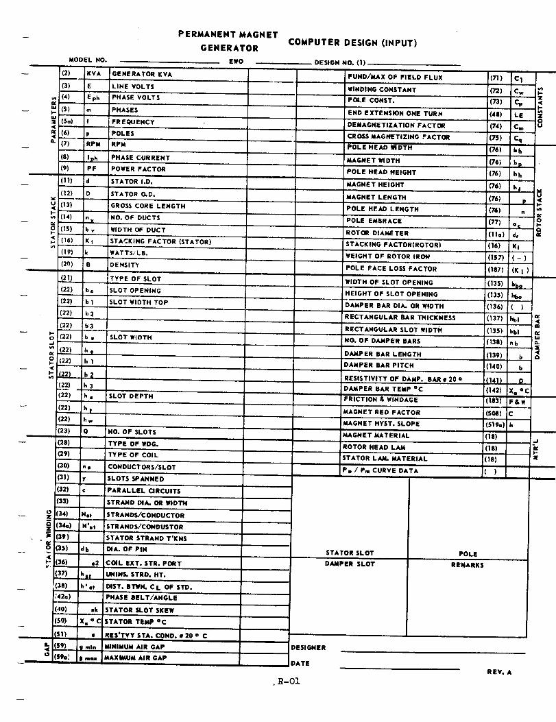
MODEL NO.
(2) KVA GENERATOR KVA
(3) E LINE VOLTS
!(4) Eph PHASE VOLTS
(S) m PHASES
So) f FREQUENCY
(6) p POLES
(7) RPM RPM
(8) Iph PHASE CURRENT
(9) PF POWER FACTORi
(11) id STATOR I.D.
(12) D STATOR O.D.
(13) GROSS CORE LENGTH.(I-
(14) n IND. OF DUCTS
O (15) b v WIDTH OF DUCT)-.
(16) K I STACKING FACTOR (STATOR)
(19) k WATTS/LB.
(20) B DEHSIT_
(21) TYPE OF SLOT
(22) bo SLOT OPENING
(22) b 1 SLOT WIDTH TOP
(22) b2
1(22) b3
t- I(22) b SLOT WIDTHO •.J
(22) [h oO_. (22) h 1<_" _2) h 2tn
(32_) h 3(22) k • SLOT DEPTH
(22) h |
(22) h w
(23) Q NO. OF SLOTS
(28) TYPE OF WDG.
(29) TYPE OF COIL
(30) n • CONDUCTORS/SLOT
(31) y SLOTS SPANNED
(32) c PARALLEL CIRCUITS
(33) STRAND DIA. OR WIDTH
(34) Nst STRANDS/CONDUCTOR
(34Q) N'st STRANDS/CONDUSTOR
(39) STATOR STRAND T'KNS
(3s) db DIA. OF PiN
I-- (36) e2 COIL EXT. STR. PORT
_[37) bet UNINS. STRD. HT.
(38) h'•t DIST. BTWN. CL OF STD.
,'42o) PHASE 8EL T/ANGLE
(40) sk STATOR SLOT SKEW
(SO) Xs o C STATOR TEMP °C
IS1) • RES*TVY STA. COND. • 20 o C
(59) g rain MINIMUM AIR GAP
O< (S9o! g mcm MAXIMUM AIR GAP
PERMANENT MAGNET
GENERATOR
EWO
COMPUTER DESIGN (INPUT)
DESIGN NO. (1)
FUND/MAX OF FIELD FLUX
WINDING CONSTANT
POLE CONST.
END EXTENSION ONE TURN
DEMAGNETIZATION FACTOR
CROSS MAGNETIZING FACTOR
POLE HEAD mDTH
MAGNET WIDTH
POLE HEAD HEIGHT
MAGNET HEIGHT
MAGNET LENGTH
POLE HEAD LENGTH
POLE EMBRACE
ROTOR DIAMETER
STACKING FACTOR(ROTOR)
WEIGHT OF ROTOR IRON
POLE FACE LOSS FACTOR
WIDTH OF SLOT OPENING
i HEIGHT OF SLOT OPENING
DAMPER BAR DIA. OR WIDTH
RECTANGULAR BAR THICKNESS
RECTANGULAR SLOT WIDTH
NO. OF DAMPER BARS
DAMPER BAR LENGTH
DAMPER BAR PITCH
RESISTIVITY OF DAMP. BAR • 20 o
DAMPER BAR TEMP °C
FRICTION & WINDAGE
MAGNET RED FACTOR
I MAGNET HYST. SLOPE
MAGNET MATERIAL
ROTOR HEAD LAM
STATOR LAM. MATERIAL
Po / Pm CURVE DATA
DESIGNER
hAT_
STATORSLOT
DAMPER SLOT
POLE
REMARKS
(71)
(72)
(48)
(74)
(7S)
(76)
(76)
(76)
(76)
(76)
(76)
(77)
(11o)
(16)
(157)
(187)
(!'35i
(13s)
C1
Cw
%
LE
Cm
cqbh
bp
hh
h!
P
n
o s
dr
KI
(-)
(KI)
(136) ( )
(137) hbi
(135) bbl
(138) nb
(139) b
(140) b
(141) D
(142) X o oC
(183) F&W
(5oa) Ic
(SI 9o) h
(18)
(18)
(18)
,( ) l
• R-OIREV. A
z,<
t_zcu
u<
4_
oI-o
<mn,.UJ
=E<Q
,.J
ivp.=E
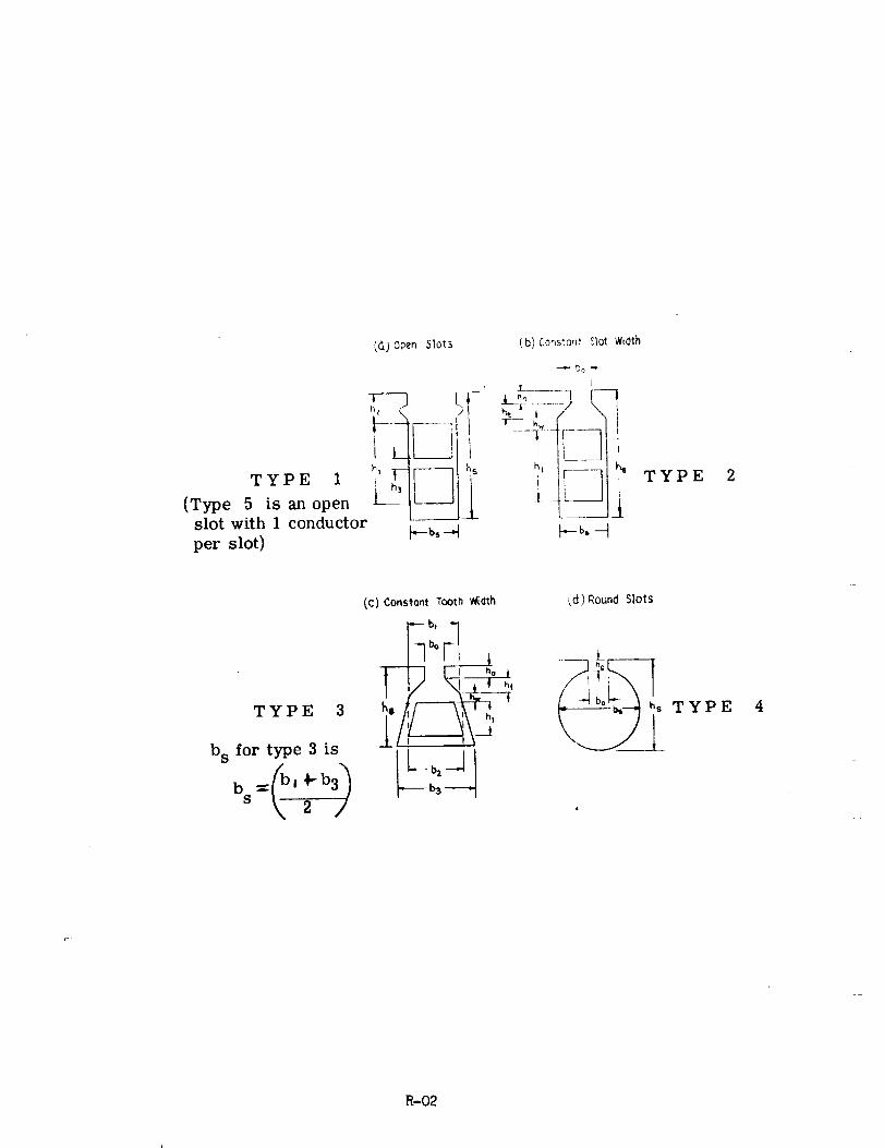
_) 0_n Slot_ (b)Cor,sto,_tSlotWidth
I -l []- _L"o......-]__
(Type 5 is an open --l_slot with 1 conductor
per slot)
TYPE 2
TYPE 3
b s for type 3 is
bs 2
(C) Constont Tooth Mclth
T_ VT- .°i/
ks , 5
(d) Round Slots
TYPE 4
R-02
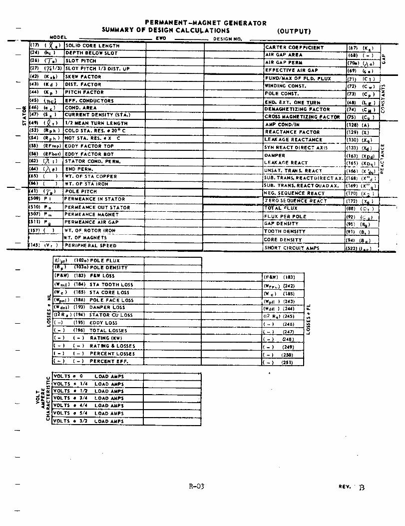
i
w- m
I-
.,(
l
(17)
(24)
(26)
(27)
MODEL
1_.1(he)
(T,)
PERMAN ENT-MAGN ET GENERATO RSUMMARY OF DESIGN CALCULATIONS
EWO
SOLID CORE LENGTH
DEPTH BELOW SLOT
SLOT PITCH
(_'_1/3) SLOT PITCH I/3 DIST. UP
[42) (K,k) SKEW FACTOR
[43) (K d ) DIST. FACTOR
i(44) (K p )
!46) (o S )
(47) (S,)
(49) (_t)
(53) (Rph)
(54) (Rp h )
(SS) (EFtop)
(_) (EFbot)
(62) (_ i )(64) (/\e)(6S) ( )
d_) ( )
PITCH FACTOR
EFF. CONDUCTORS
COND. AREA
!CURRENT DENSITY (STA.)
!!/2MEAN TURN LENGTH
COLDSTA. RES. e20°C
HOT STA. RES. # X C
EDDY FACTOR TOP
EDDY FACTOR BOT
STATOR COND. PERM.
END PERM.
WT. OF STA COPPER
WT. OF STAIRON
POLE PITCH(41) (7"=)[509) P I PERMEANCE IN STATOR
(5101 Po PERMEANCE OUT STATOR
(507) Pm PERMEANCE MAGNET
[5111 Pg PERMEANCE AiR GAP .............
( ) WT. OF ROTOR IRON
WT. OF MAGNETS
_V'r ) - PERIPHERAL SP'EED
DESIGN NO.
(OUTPUT)
CARTER COEFFICIENT
AiR GAP AREA
AiR GAP PERM
EFFECTIVE AIR GAP
FUND/MAX OF FLD. FLUX
WINDING CONST.
POLE CONST.
iENI_ EXT. ONE TURN
DEMAGNETIZING FACTOR
CROSS MAGNETIZING FACTOR
AMP COND/IN
REACTAJHCE FACTOR
LEAK AGE REACTANCE
SYN REACT DIRECT AXIS
DAMPER
LEAKAGE REACT
UNSAT. TRANS. REACT
SUB. TRANS. REACT DIRECT AX.
SUB. TRANS. REACT QUAO AX.
NEG. SEQUENCE REACT• II III ---
ZERO SEQUENCE REACT
.... TOTAL _L LI'X
FLUX PER POLE
GAP DENSITY
TOOTH DENSITY
CORE DENSITY
SHORT CIRCUIT AMPS
,.I
Z
U
<xu
f/Jp,) (1_o) POLE FLUX
'(B p) (103a) POLE DENSITY
(F&W) (183) F&W LOSS (F&W) (1'83'i'_
4Wmi ) 41841 STA TOOTH LOSS (WrrL} (242)
(Wc) (1851 STA CORE LOSS (We) 41851
(V/Fn I) 4186) POLE FACE LOSS
(Wdni) (193) DAMPER LOSS
(12R,) (1941 STATOR CU LOSS
(-) 419';) EDDY LOSS
(- ) (196) TOTAL LOSSES
(-) (-) RATING(KW)
( - ) (- ) RATING & LOSSES
( - ) ( - ) PERCENT LOSSES
( - ) (-) PERCENT EFF.
VOLTS • 0 LOAD AMPS
VOLTS _ i/4 LOAD AMPS
VOLTS • 1/2 LOAD AMPS
VOLTS • 3/4 LOAD AMPS
VOLTS • 4/4 LOAD AMPS
VOLTS • 5/4 LOAD AMPS
VOLTS • 3/2 LOADAMPS
i(Wpfl ) (243)
(Wdfl) (244)
(12 Rs) (245)
( - ) <246)
( - ) (2471
(- ) (z4e)(-) (249)
( - ) (2so)(- ) 42SI)
o..J
(67) (K•)
(68) (-)
(7_)((\ o)(69) 4s °)
{711 (C I )
(72) (C w )
(73) (C p )
(48) (LE)
(74) (CM )
(1281(A)41291 (x)
(13o) (xq)(1331 (Xd ,"
(I_)(XPd)
;41681 (x" d)
(169) (__'_'_d
(170) (Xl,)
(!7_)I iX_ )
(88) (_':,)
4951(_)!(91) (S t )
(94) (Be)
(5221 (I ._ )
m
uJ
h
R-03 REV, z-_

DESIGN MANUAL
FOR
PERMANENT MAGNET, AoC. GENERATORS
INTRODUCTION
The calculation procedure given here is for only one configuration of
permanent magnet generators. It is the classical design with
definite poles consisting of blocks of magnet material. The
pole heads are designed to support the magnets and are usually
wider than the magnet blocks. Sometimes the pole heads are
designed to provide high out-of-stator flux leakage and thereby
cause the magnet material to stay magnetized at a high level of
flux density even when air-stabilized.
R-1
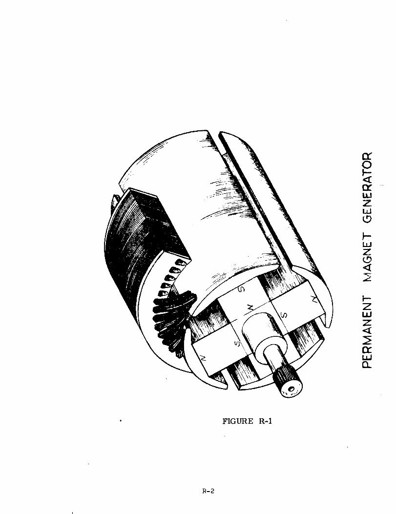
:Z
IX"
£<[
ILlZWL,9
F'-"ILlZ',D<
t--ZI,LlZ
fv.
IX.
FIGURE R-I
1R-2
The following sketch illustrates the leakage fluxes that are calculated
in determining the performance of the permanent magnet gen-
erators covered by this design manual. The formulae and the
designations for the permeance calculations are taken from
Strauss "Synchronous Machines with Rotating Permanent Magnet
Fields" Trans. AIEE 1952 Part II, pp. 887-893. Formulae
from Roter's "Electromagnetic Devices" a Wiley and Sons book,
are appended to this report, and can be used to estimate
permeances for configurations of PM generators different from
the one discussed in this manual.
/
FIGURE R= 2
When the rotor is magnetized and then removed from the magnetizing
fixture without a keeper, the magnet flux density will decrease
to a value determined by the out-of-stator leakage permeance.
This leakage permeance consists of all of the flux leakage
permeances of the rotor when the rotor is out of the stator.
When the rotor is placed in position in the stator, some of the flux
that leaked from pole-to-pole when the rotor was by itself,
now becomes useful flux by flowing through the stator iron and
linking the conductors in the output winding.
R-4a
These rotor flux leakage permeances are separated into discrete leak-
age paths and are illustrated separately in the following
sketches:
0
FIGURE R-3
R-5
P1 = The pole-to-pole side leakage permeance. This leakage exists
when the rotor is in the stator as well as when it is out and
is just unuseable leakage flux.
The formula here is taken from Strauss:
Pl : 3-19---P _p
for poles that touch at the base, and
for poles not touching at the base.

j-/. ..........I
"- /- - J-
_ ///
_. ___ /,'/J/ /_, .......:/ / / /
/
//I
I
R-9
%
, Ii \_ ./" I!1 \,'" V" I" I\
l i' I l\I I ,
I
/ I
FIGURE R-6
Ps = the permeance of the flux leakage path from the centerline of
one pole-head surface to the centerline of the adjacent poleo
head surface.
This leakage is part of the out-stator leakage but does not exist when
the rotor is inserted in the stator.
_s:_0__
0
\
\\
Pf = the permeance of the flux leakage path between the adjacent ends
of the pole heads.
This leakage flux is part of the out-stator leakage but no longer exists
when the rotor is placed in the stator.
,¢322_r-bh)
Pf =._o.,_'p O. = 1.661. 220(_-_)
Pf = 1.66
0
I [ [I , ' , L; |
i! , i/
..................... __.......=..... _........................../ ............... _..... __
7 i ! '
o ,5 #- ,5POLE
...................... _[ ................
,F_ ,7EMBRACE
....... t
I
FIGURE R-8
R-IO
FIGURE R-9
O
\\
/
N-II
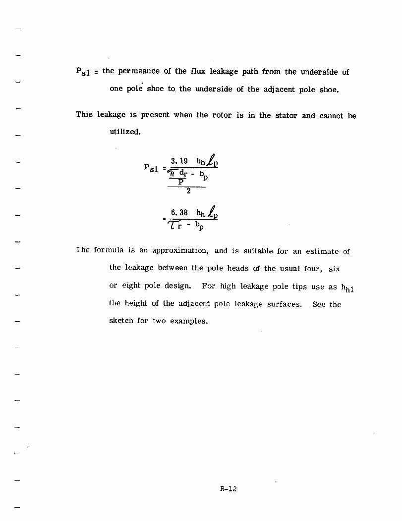
Psl - the permeance of the flux leakage path from the underside of
one pole shoe to the underside of the adjacent pole shoe.
This leakage is present when the rotor is in the stator and cannot be
utilized.
3.19 hhlp
Psl--_--dr " bpP
2
The formula is an approximation, and is suitable for an estimate of
the leakage between the pole heads of the usual four, six
or eight pole design. For high leakage pole tips use as hhl
the height of the adjacent pole leakage surfaces. See the
sketch for two examples.
R-12
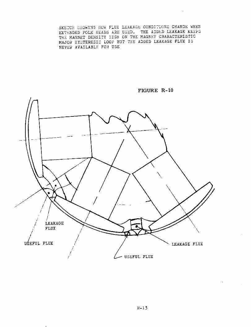
SKETCHSHOWING!!OWFLUXLEAKAGECONDITIONSCHANGEWHENEXTENDEDPOLEHEADSAREUSED. THEADDEDLEAKAGEKEEPSTHE MAGNETDENSITY}iIGH ONTHEMAGNETCHARACTERISTICMAJORHYSTERESISLOOPBUT THE ADDEDLEAKAGEFLUXISNEVERAVAILABLEFORUSE
FIGURE R- I0
i // LEAKAGE
FLUXJ
/
/
U_/EFUL FLUX
/
/
/!
/
/./
/
_.--'USEFUL FLUX
\
\
\
LEAKAGE FLUX
R-13
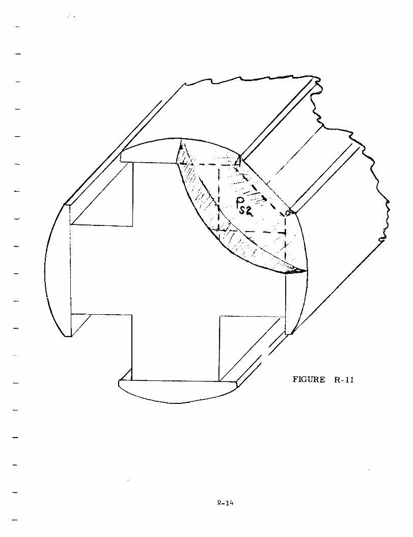
FIGURE
R-14
R-11
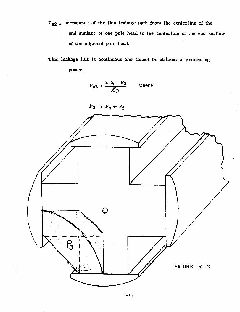
Ps2 --permeance of the flux leakage path from the centerline of the
end surface of one pole head to the centerline of the end surface
of the ad)acent pole head.
This leakage flux is continuous and cannot be utilized in generating
power.
2 hn P2 where
Ps2 - _p
P2 - Ps+Pf
/
/
I
O
FIGURE R-12
R-15
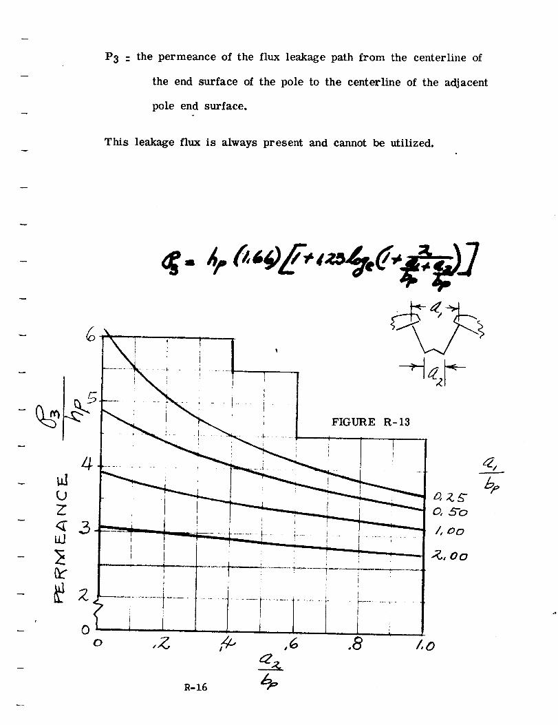
P3 : the permeance of the flux leakage path from the centerline of
the end surface of the pole to the centerline of the adjacent
pole end surface.
This leakage flux is always present and cannot be utilized.
4
00
R-16
When the rotor is inserted in the stator, the pole-to-pole flux that
passed through the permeance paths, Ps 11" Pf is no longer
present as leakage flux. That flux now enters the stator and
becomes useful flux.
All of the flux passing through the other pole-to-pole permeance paths
is leakage flux that cannot be utilized.
Pi = in-stator leakage permeance
Pi -- Po - P2
For convenience, the leakage permeance consisting of the sum of all
the permeance paths, through which flux leaks pole-to-pole
when the rotor is out of the stator is called Po = out-stator
permeance.
The sum of the pole-to-pole leakage permeance existing when the rotor
is installed in the stator is called the in-stator permeance (Pi).
The permeances of the various flux paths have been calculated at this
point in the design procedure. They could be used just as they
are used in an electromagnetic generator in which case the mag-
net characteristics would be plotted in terms of total ampere-
turns and total magnet flux. This procedure would require a
special flux plot for each generator desigru
R-17
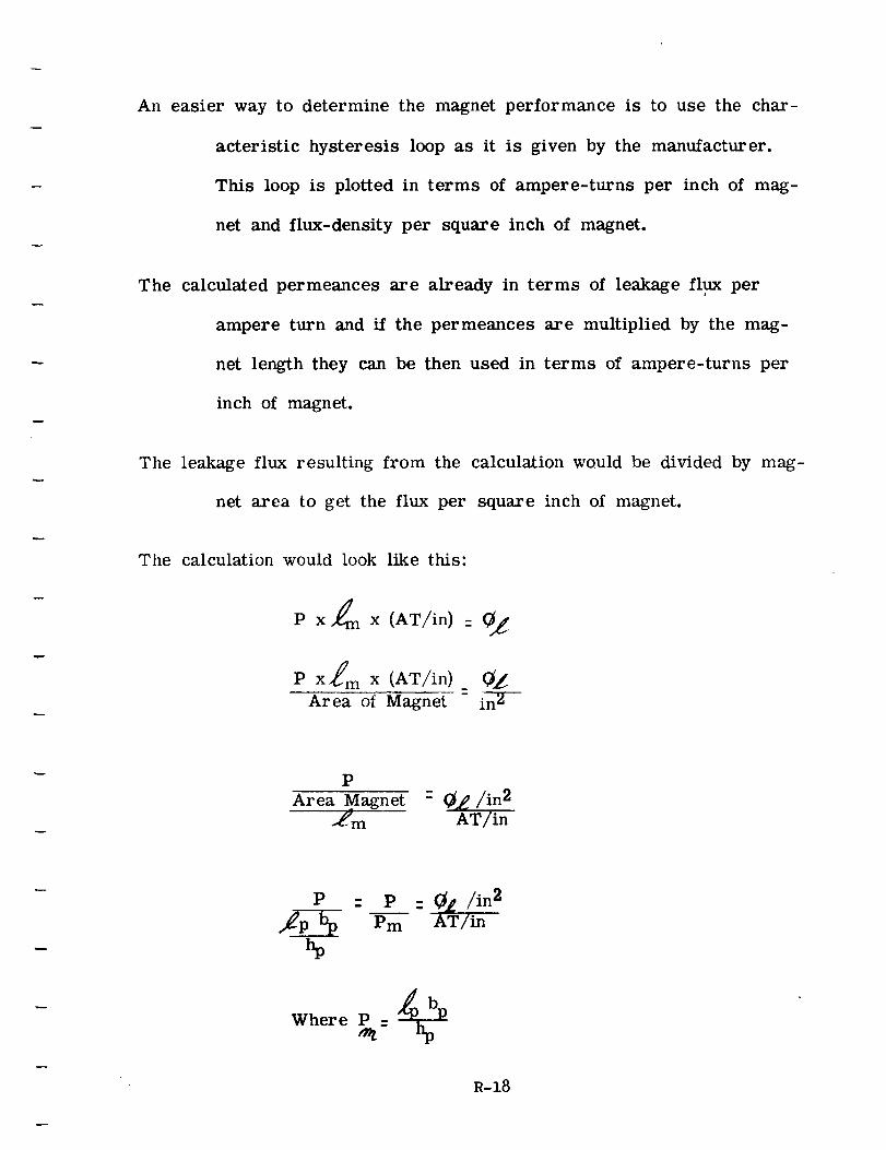
An easier way to determine the magnet performance is to use the char-
acteristic hysteresis loop as it is given by the manufacturer.
This loop is plotted in terms of ampere-turns per inch of mag-
net and flux-density per square inch of magnet.
The calculated permeances are already in terms of leakage flux per
ampere turn and if the permeances are multiplied by the mag-
net length they can be then used in terms of ampere-turns per
inch of magnet.
The leakage flux resulting from the calculation would be divided by mag-
net area to get the flux per square inch of magnet.
The calculation would look like this"
P x £ x (AT/in) = 0_
P x_ m x (AT/in)
Area of Magnet
P
Area Magnet - 0_/i n2
_m AT/in
P : P - (_1 / in2
b_ Pm AT/in
Where P ='9
R-18
The ideal permanent magnet generator might have high flux leakage in
the rotor when the rotor was out-of-stator and low flux leakage
when therotor was inserted in the stator, except that the machine
would, in nearly all cases be capable of demagnetizing itself
when subjected to a transient or short circuit.
The two following sketches illustrate how a choice is made between
magnet materials just on the basis of the out-of-stator leakage
characteristic.
The in-stator leakage must be considered in determining whether or not
the generator can withstand short circuits and transients with-
out loss of properties.
R-19
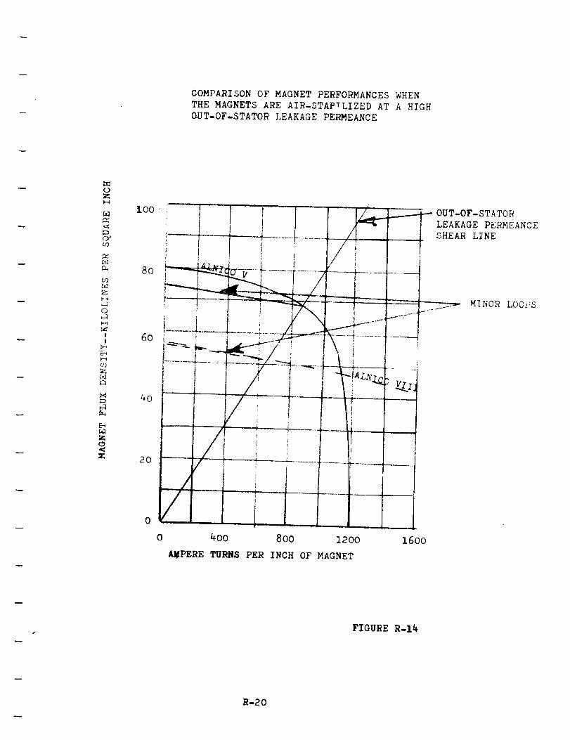
COMPARISON OF MAGNET PERFORMANCES WHEN
THE MAGNETS ARE AIR-STAPTLIZED AT A HIGH
GUT-OF-STATOR LEAKAGE PERMEANCE
_D
.<
C_09
O_
u_O_
P-4
0
1I
u_
A
X
b-,
8o
4o
2o
0
Ii
400 800 1200
AMPERE TURNS PER INCH OF MAGNET
.___--_OUT-OF-STATORLEAKAGE PERMEANCE
SHEAR LINEf
MINOR LO0]_S
16oo
FIGURE R-14
R-20
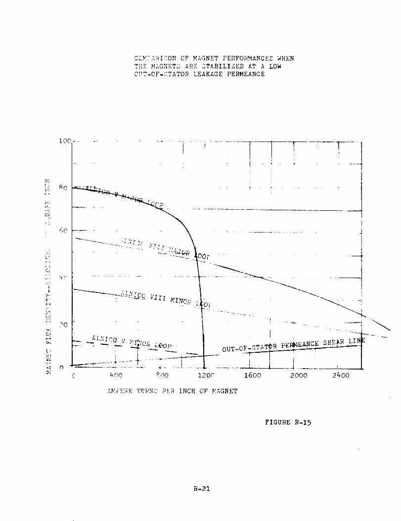
CCMTARICONOF MAGNETPERFORMANCESWHENTHE MAGNETSABESTABILIZED AT A LOWOUT-OF-_:TATORLEAKAGEPERMEANCE
(>
• I]
:d
O
|
!
>.
h:
[,
hl
Z
IOC
_0
60
2O
O
.................................._........]i
f
rr I ' _ "
: I
..... ,,,,. ........ _ ,. ....
" r _., '#_) .......... iiii ......i....iiOOF
t
..... _ "--- i-J ;@OP •
C aO0 800 .200 16OO
!
.... j
n_T_OF-STAT_ R pEI_EANCE___SHEAR: LIN
I
2000 2400
,,E_,,RE TURN£ P_R INCH OF YAGNET
FIGURE R-15
R-21
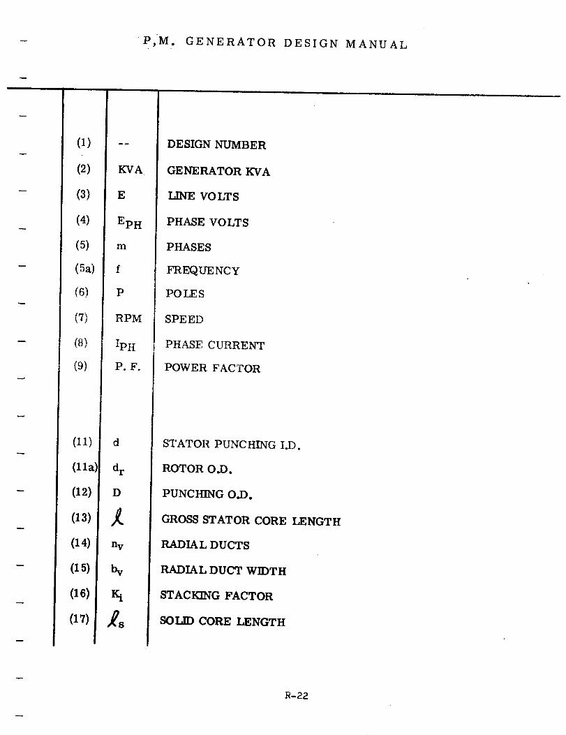
- P,M. GENERATOR DESIGN MANUAL
(1)
(2)
-- (3)
(4)
(5)
- (5a)
(6)
(7)
- (8)
(9)
(II)
(lla)
(12)
(a3)
(14)
(15)
(16)
(17)
KVA
E
EpH
m
f
P
RPM
_PH
P.F.
d
d r
D
n V
bv
Iq
DESIGN NUMBER
GENERATOR KVA
LINE VOLTS
PHASE VOLTS
PHASES
FREQUENCY
POLES
SPEED
PHASE CURRENT
POWER FACTOR
STATOR PUNCHING I.D.
ROTOR O.D.
PUNCHING O.D.
GROSS STATOR CORE LENGTH
RADIA L DUCTS
RADIAL DUCT WIDTH
STACKING FACTOR
SOLID CORE LENGTH
R-22
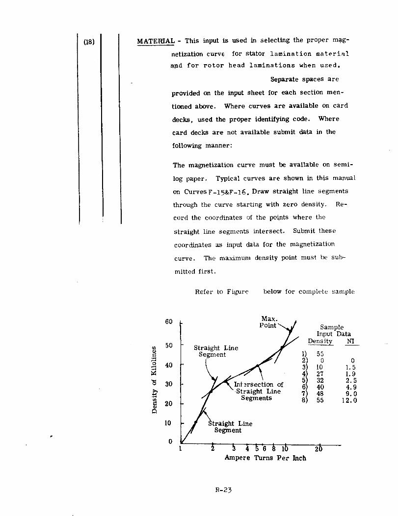
(18) MATERIAL- This input is used in selecting the proper mag-
netization curve for stator lamination material
and for rotor head laminations when used.
Separate spaces are
provided on the input sheet for each section men-
tioned above. Where curves are available on card
decks, used the proper identifying code. Where
card decks are not available submit data in the
following manner:
The magnetization curve must be available on semi-
log paper. Typical curves are shown in this manual
on Curves F-15&F-16. Draw straight line segments
through the curve starting with zero density. Re-
cord the coordinates of the points where the
straight line segments intersect. Submit these
coordinates as input data for the magnetization
curve. The maximum density point must be sub-
mitted first.
Refer to Figure below for complete sample
6O
50¢9
o 40M
30
_ 2O¢lJ
10
0
Max.
Point
Straight Line _ I) 55
Segmln_/f i/
2043 lO3240
_ ".St_raight Line 48
_ Segments 55
J Straight- Line
Segment
Ampere Turns Per Inch
SampleInput Data
Density NI
01.51.92.54.99.0
12.0
R-23
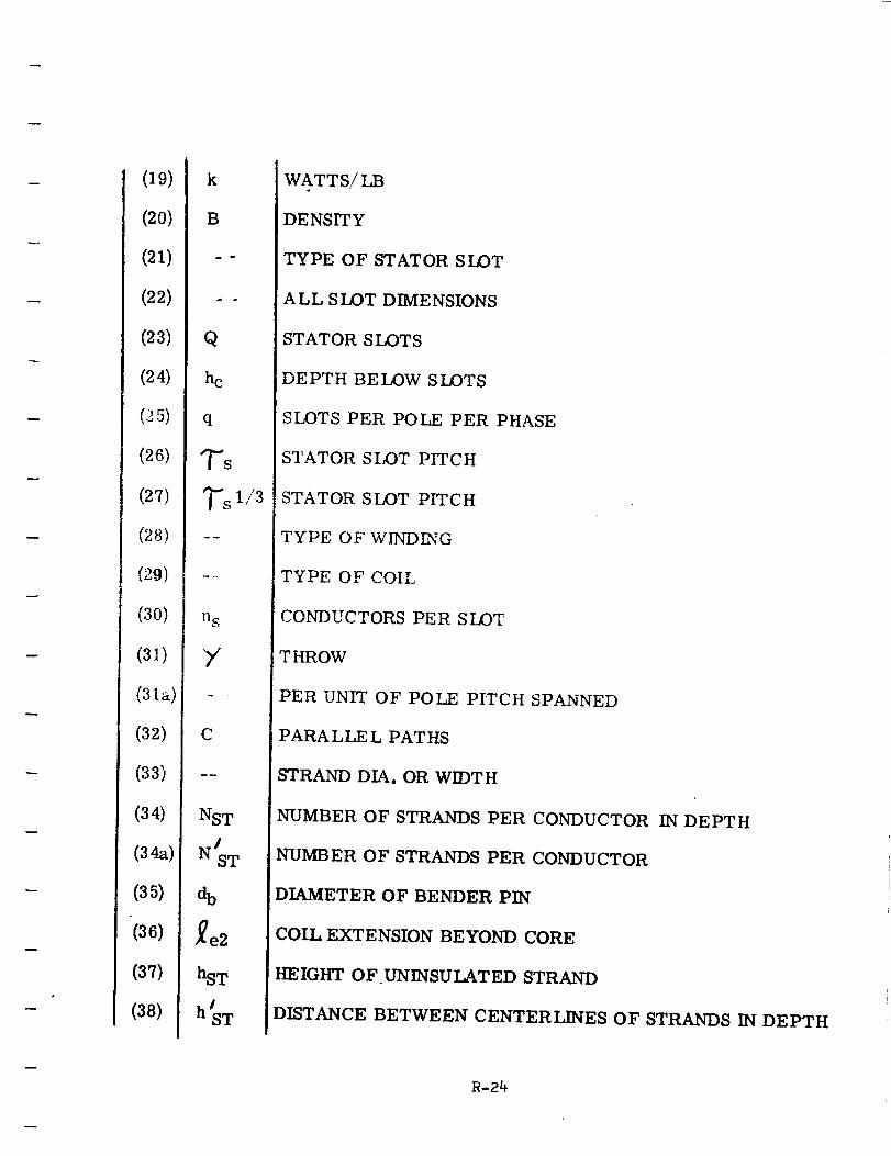
(19)
(20)
(21)
(22)
(23)
(24)
(_5)
(26)
(27)
(28)
(29)
(30)
(31)
(31a)
(32)
(33)
(34)
(34a)
(3_)
(36)
(37)
(38)
k
B
Q
hc
q
%1/3
n S
Y
C
NST
ab
re2
hsT
nJsw
WATTS/LB
DENSITY
TYPE OF STATOR SLOT
ALL SLOT DIMENSIONS
STATOR SLOTS
DEPTH BELOW SLOTS
SLOTS PER POLE PER PHASE
STATOR SIOT PITCH
STATOR SLOT PITCH
TYPE OF WLNDING
TYPE OF COIL
CONDUCTORS PER SLOT
THROW
PER UNIT OF POLE PITCH SPANNED
PARALLE L PATHS
STRAND DIA. OR WIDTH
NUMBER OF STRANDS PER CONDUCTOR IN DEPTH
NUMBER OF STRANDS PER CONDUCTOR
DIAMETER OF BENDER PIN
COIL EXTENSION BEYOND CORE
HEIGHT OF UNINSULATED STRAND
DISTANCE BETWEEN CENTERLINES OF STRANDS IN DEPTH
R-24
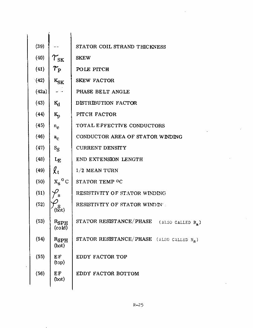
(39)
(40)
(41)
(42)
(42a)
(43)
(44)
(45)
(46)
(47)
(48)
(49)
(50)
(51)
(52)
(53)
(54)
(55)
(56)
KSK
_h
%
ne
a c
S S
LE
Xs ° C
RSPH(corn)
RSPH
(hot)
EF
(top)
EF
(Dot)
STATOR COIL STRAND THICKNESS
SKEW
POLE PITCH
SKEW FACTOR
PHASE BELT ANGLE
DISTRIBUTION FACTOR
PITCH FACTOR
TOTAL EFFECTIVE CONDUCTORS
CONDUCTOR AREA OF STATOR WINDING
CURRENT DENSITY
END EXTENSION LENGTH
1/2 MEAN TURN
STATOR TEMP oc
RESISTIVITY O F STATOR WINDING
RESISTIVITY OF STATOR WINDIN¢.
STATOR RESISTANCE/PHASE
STATOR RESISTANCE/PHASE
(ALSO CALLED Ra)
(ALSO CALLED Ra)
EDDY FACTOR TOP
EDDY FACTOR BOTTOM
R-25
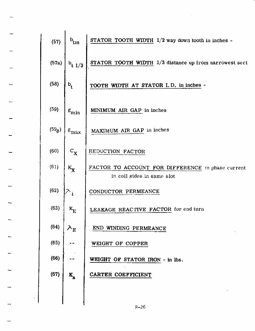
(57)
(57a)
(58)
(59)
(59_)
(60)
(61)
(62)
(63)
(64)
(65)
(66)
(67)
btm
bt 1/3
b t
gmin
gmax
C x
Kx
_- o
1
KE
/A E
Ks
STATOR TOOTH WIDTH 1//2way down tooth in inches -
STATOR TOOTH WIDTH 1/3 distance up from narrowest sect
TOOTH WIDTH AT STATOR I.D. in inches -
MINIMUM AIR GAP in inches
MAXIMUM AIR GAP in inches
REDUCTION FACTOR
FACTOR TO ACCOUNT FOR DIFFERENCE in phase current
in coil sides in same slot
CONDUCTOR PERMEANCE
LEAKAGE REACTIVE FACTOR for end turn
END WINDING PERMEANCE
WEIGHT OF COPPER
WEIGHT OF STATOR IRON - in lbs.
CARTER COEF_CIENT
R-26
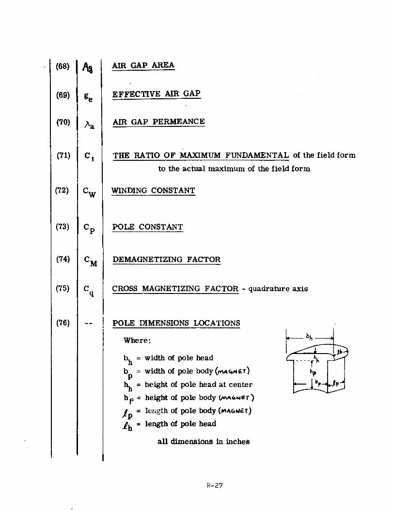
(68)
(69)
(70)
(71)
(72)
(73)
(74)
(75)
(76)
&
ge
C 1
_W
Cp
C M
Cq
AIR GAP AREA
EFFECTIVE AIR GAP
AIR GAP PERMEANCE
THE RATIO OF MAXIMUM FUNDAMENTAL of the field form
to the actual maximum of the field form
WINDING CONSTANT
POLE CONSTANT
DEMAGNETIZING FACTOR
CROSS MAGNETIZING FACTOR - quadrature axis
POLE DIMENSIONS LOCATIONS
Where:
b h = width of pole head
b = width of pole body (r_N._'r)p
hh = height of pole head at center
h p = height of pole body Ov_er)
_p = length of pole body (_^_._T)
_$h = length of pole head
all dimensions in inches
R-27
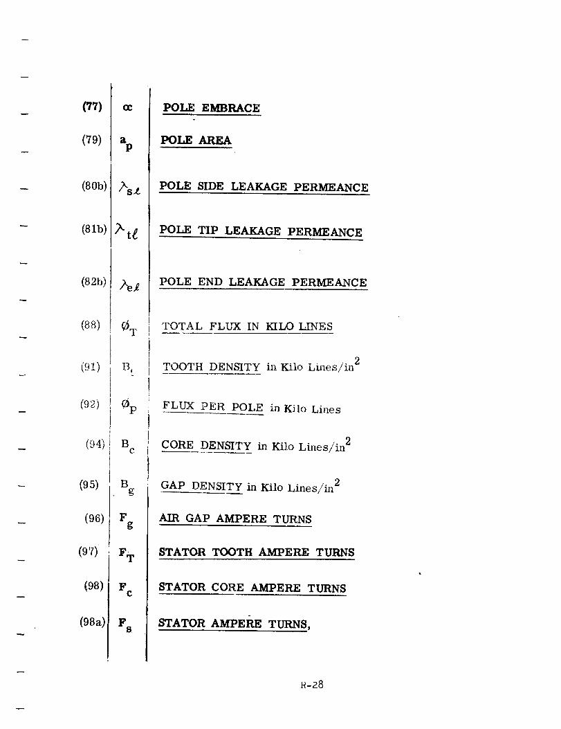
(77)
(79)
(80b)
(81b)
(82b)
(88)
(91)
(92)
(_4_
(95)
(96)
(97)
(98)
(98a)
(}C
StP
/ksZ
/xe_
0 T
B t
0p
Bc
Bg
Fg
Fw
F C
F s
POLE EMBRACE
POLE AREA
POLE SIDE LEAKAGE PERMEANCE
POLE TIP LEAKAGE PERMEANCE
POLE END LEAKAGE PERMEANCE
TOTAL FLUX IN KILO ._ES
TOOTH DENSITY in Kilo Lines/in 2
FLUX PER POLE in Kilo Lines
CORE DENSITY in Kilo Lhms/in 2
GAP DENSITY in Kilo Lines/in 2
AIR GAP AMPERE TURNS
STATOR TOOTH AMPERE TURNS
STATOR CORE AMPERE TURNS
STATOR AMPERE TURNS,
R-28
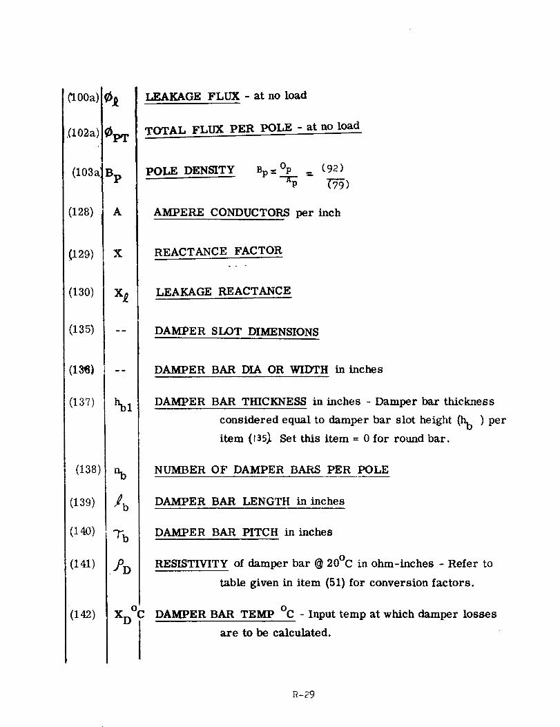
OOa)
,(102a)J
(103a]
(128)
(129)
(130)
(135)
(137)
(138)
(139)
(14o)
(141)
(i42)
_P'r
-p
A
X
hbl
%
_b
%
XD°C
LEAKAGE FLUX - at no load
TOTAL FLUX PER POLE - at no load
POLE DENSITY Bp_--Op _ (92)
AMPERE CONDUCTORS per inch
REACTANCE FACTOR
LEAKAGE REACTANCE
DAMPER SLOT DIMENSIONS
DAMPER BAR DIA OR WIDTH in inches
DAMPER BAR THICKNESS in inches -Damper bar thickness
considered equal to damper bar slot height (hb ) per
item (1357 Set this item = 0 for round bar.
NUMBER OF DAMPER BARS PER POLE
DAMPER BAR LENGTH in inches
DAMPER BAR PITCH in inches
RESISTIVITY of damper bar @ 20°C in ohm-inches - Refer to
table given in item (51) for conversion factors.
DAMPER BAR TEMP °C - Input temp at which damper losses
axe to be calculated.
R-29
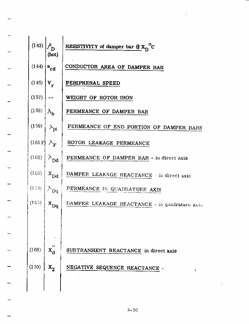
(143)
(144)
(145)
(157)
(158)
(159)
(161 F:
(162)
(1_3)I
(1Gs)
(168)
(17o)
7 D
(hot)
acd
Vr
•
XDd
?'Dq
XDq
_v
X d
X 2
RESISTIVITY of damper bar @ XD°C
CONDUCTOR AREA OF DAMPER BAR
PERIPHERAL SPEED
WEIGHT OF ROTOR IRON
PERMEANCE OF DAMPER BAR
PERMEANCE OF END PORTION OF DAMPER BARS
ROTOR LEAKAGE PERMEANCE
PERMEANCE OF DAMPER BAR - in direct axis
DAMPER L 'EAKAGE REACTANCE 11] direct axis
PERMEANCE IN QUADRATURE AXIS
I
DAMPER LEAKAGE REACTANCE - in quadrature a_._:_
SUBTRANSIENT REACTANCE in direct axis
NEGATIVE SEQUENCE REACTANCE -
R-30
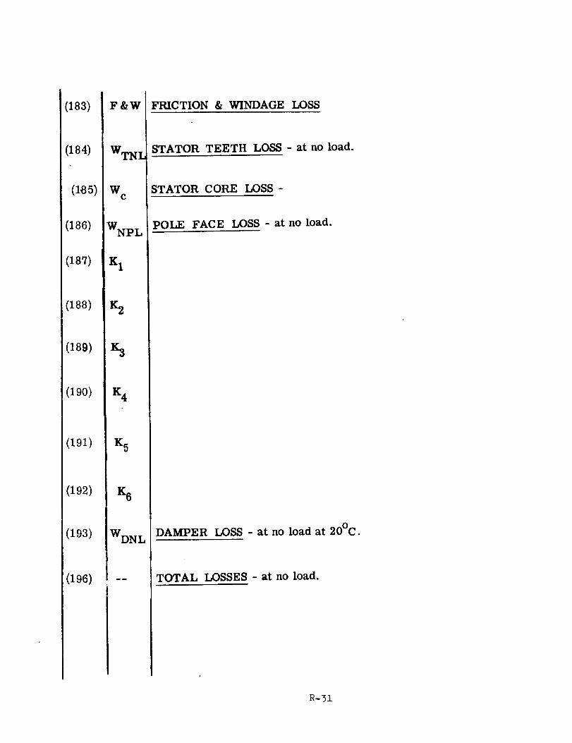
(183)
(184)
(185)
(186)
(187)
(188)
(189)
(190)
(191)
(192)
(193)
(196)
F&W
WTNI
W E
WNPL
K 1
Z2
Z3
K 4
K 5
K 6
WDNL
FRICTION & WINDAGE LOSS
STATOR TEETH LOSS - at no load.
STATOR CORE LOSS -
POLE FACE LOSS - at no load.
DAMPER LOSS - at no load at 20°C.
TOTAL LOSSES - at no load.
i_-31
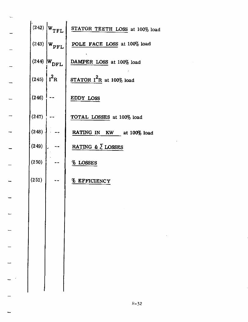
"(242) WTF L
(243) IWpFL
(244) IWDFL
(245) [I2R
(247) --
(248) , -,
(249) --
(250) --
(251) --
STATOR TEETH LOSS at 100% load
POLE FACE LOSS at 100% load
DAMPER LOSS at 100% load
/
STATOR I2R at 100% load
EDDY LOSS
TOTAL LOSSES at 100% load
RATING IN KW at 100% load
RATING & I LOSSES
% LOSSES
% EFFICIENCY
R-32
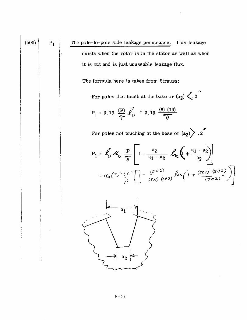
(500) P1 The pole-to-pole side leakage permeance. This leakageurJ
exists when the rotor is in the stator as well as when
it is out and is just unuseable leakage flux.
The formula here is taken from Strauss:
For poles that touch at the base or (a2) <. 2 ,t
/: (6)(76)Pl : 3.19 _Vp = 3.19
dFor poles not touching at the base or (a2) .2
Pl
R-33
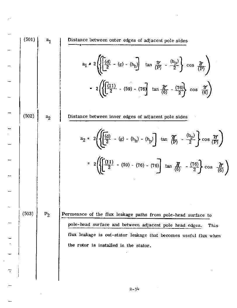
(5oi)
(502)
(503)
aI
a2
P2
Distance between outer edges of adjacent pole sides
Distance between inner edges of adjacent pole sides
- (g)- (hh) - (hp)_ 2 cos
(59)- (76)- (76)_ tan _ --(76-)}cos _)
Permeance of the flux leakage paths from pole-head surface to
pole-head surface and between adjacent pole head edges. This
flux leakage is out-stator leakage that becomes useful flux when
the rotor is installed in the stator.
R-34
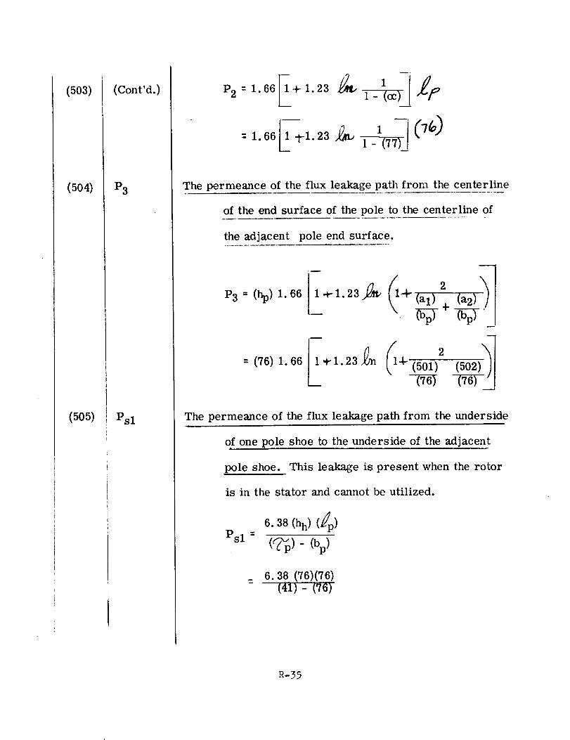
(503)
(504)
(505)
(Cont'd.)
P3
Psl
P21
l- (0c) _]o
1 r1-(77L
The permeance of the flux leakage path from the centerline
of the end surface of the pole to the centerline of
the adjacent pole end surface.
P3 _ (hp)1.66
= (76) 1.66 _r 1.23 4- (501)2
The permeance of the flux leakage path from the underside
of one pole shoe to the underside of the adjacenti
pole shoe. This leakage is present when the rotor
is in the stator and cannot be utilized.
6.38 (hh) (fp)
Psl= (%1- (bp)
6.38 (76)(76)
- (41)- (76)
R-35
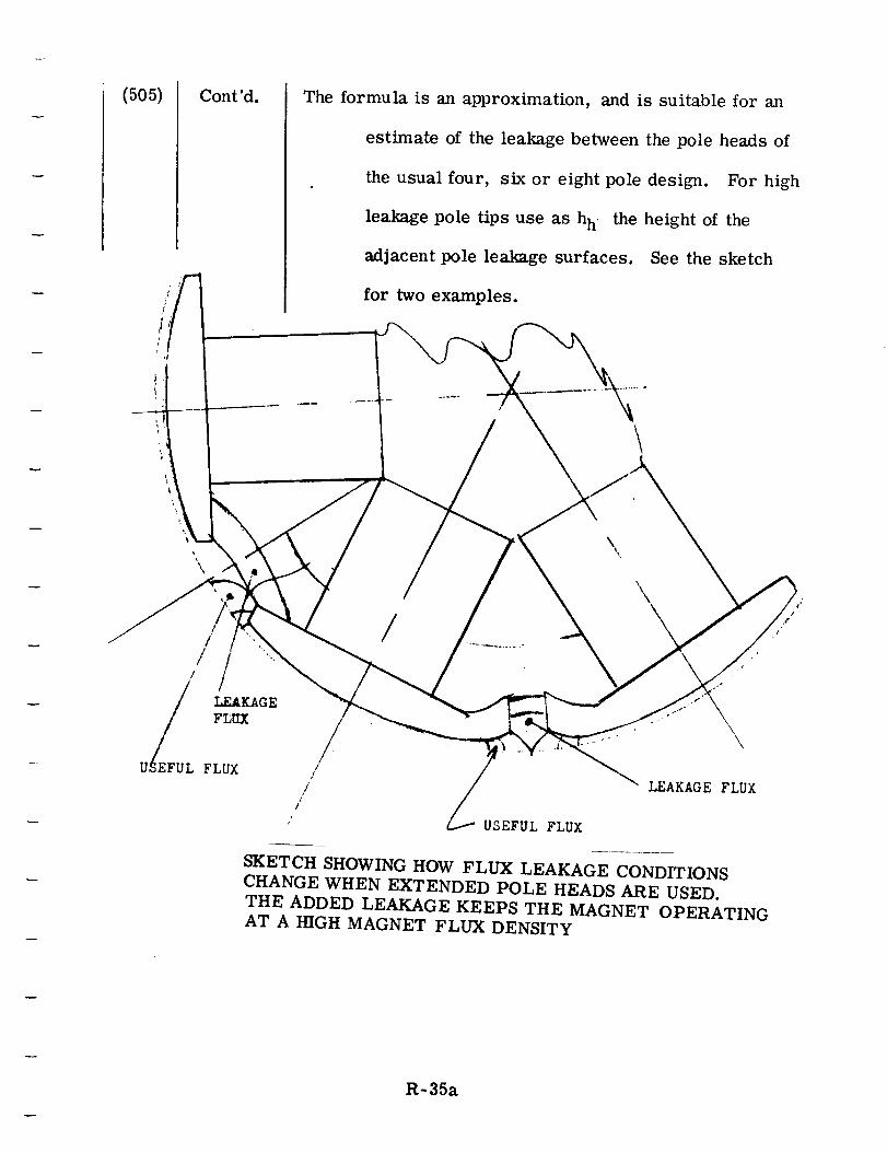
(505) Cont'd.
/ /'
The formula is an approximation, and is suitable for m_
estimate of the leakage between the pole heads of
the usual four, six or eight pole design. For high
leakage pole tips use as h h the height of the
adjacent pole leakage surfaces. See the sketch
for two examples.
i
/
//
_L LEAKAGE
FIXIX
U FLUX
\
\
USEFUL FLUX
\\
LEAKAGE FLUX
SKETCH SHOWING HOW FLUX LEAKAGE CONDITIONS
CHANGE WHEN EXTENDED POLE HEADS ARE USED.
THE ADDED LEAKAGE KEEPS THE MAGNET OPERATINGAT A HIGH MAGNET FLUX DENSITY
R-35a
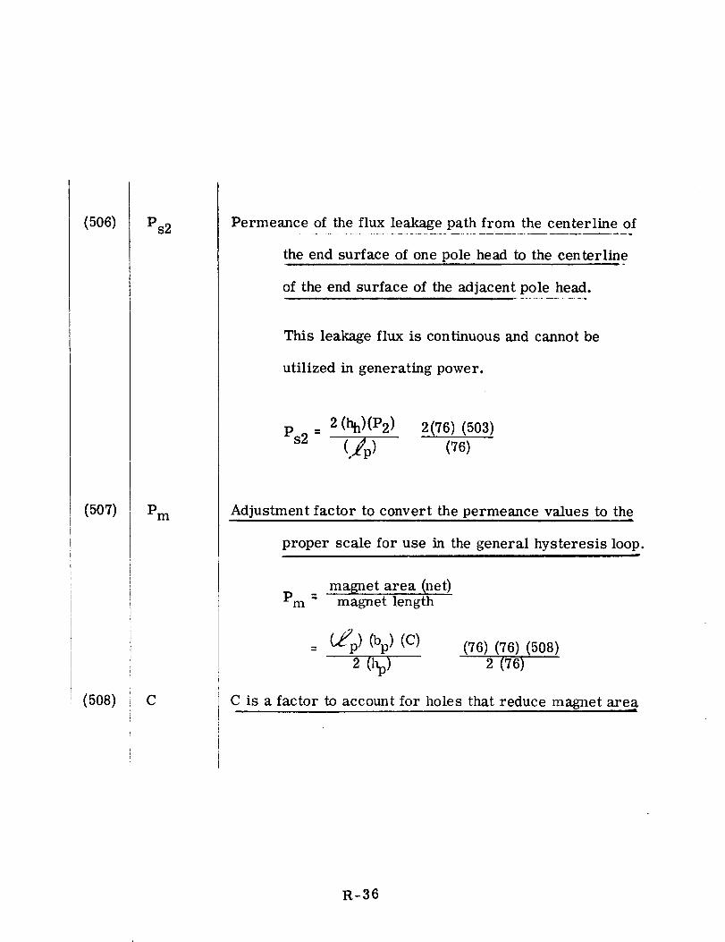
(506)
(507)
(508)
Ps2
Pm
C
Permeance of the flux leakage path from the centerline of
the end surface of one pole head to the centerline
of the end surface of the adjacent pole head.
This leakage flux is continuous and cannot be
utilized in generating power.
2 (hh)(P2) 2(76) (503)
Ps2 - (76)
Adjustment factor to convert the permeance values to the
proper scale for use in the general hysteresis loop.n_
magnet area (net)Pm- magnet length
(_p) (bp)(C) (76) (76)(508)
2 (hp) 2 (76)
C is a factor to account for holes that reduce magnet area
R-36
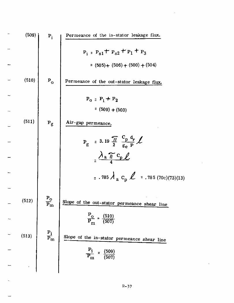
(509)
(51o)
(511)
(512)
(5a3)
Pi
Po
Pg
Pol
Pm
Permeance of the in-stator leakage flux.|lJ
Pi : Psl "#- Ps2 "#"P1 _" P3
= (505)+ (506) t (500) + (504)
Permeance of the out-stator leakage flux.
Po - Pi + P2
= (509) 4- (503)
Air-gap permeance.i
C_d_/p : 3.19 _.,L
g 2 ge p
a Cp .785 (70c)(73)(13)
Slope o£ the out-stator permeance shear line
Po_ (510)
Pm (50-5-0_
Slope.. of the in-stator permeance shear line
Pi . (509)
P,n (507)
R-57
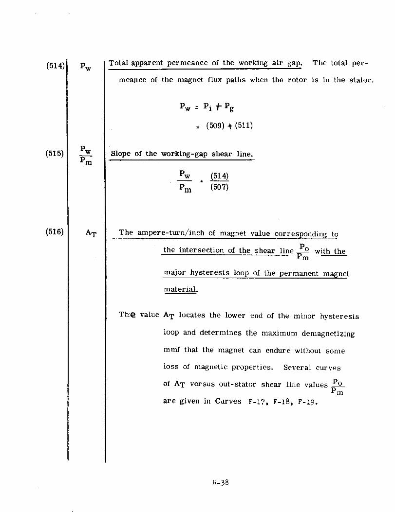
(514)
(515)
(516)
Pw
Pm
A T
Total apparent permeance of the working air gap. The total per-
mealace of the magnet flux paths when the rotor is in the stator.
Pw : Pi _" Pg
= (509) _¢(511)
Slope of the working-gap shear line.
Pw (514)
Pm (507)
The ampere-tin-n/inch of magnet value corresponding to
PO
the intersection of the shear line_--_m with the
major hysteresis loop of the permanent magnet
material.
Tb:@ value A T locates the lower end of the minor hysteresis
loop and determines the maximum demagnetizing
mmf that the magnet can endure without some
loss of magnetic properties. Several curves
of AT versus out-stator shear line values PoPm
are given in Carves F:-lT, F-18, F-19.
R-38
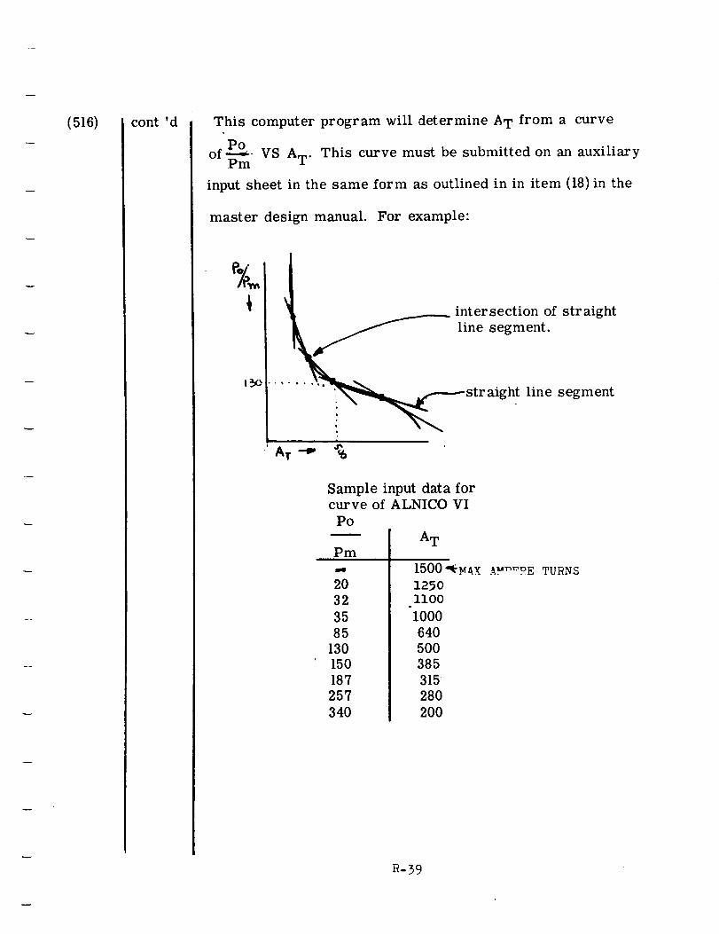
(516) cont 'd This computer program will determine A T from a curve
of P-_°- VS A T. This curve must be submitted on an auxiliaryPm
input sheet in the same form as outlined in in item (18) in the
master design manual. For example:
%
A T -_
intersection of straight
line segment.
ht line segment
Sample input data forcurve of ALNICO VI
POi
Pm
20
32
35
85
130
150
187
257
340
A T
1500"_N_x _E
1250ii00
1000
640
50O
385
315
280
200
TURNS
R-39
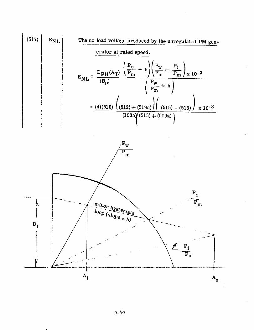
(517) ENL The no load voltage produced by the unregulated PM gen-
erator at rated speed.
ENL -
EpH(AT ) _ ÷ h Pm Pm x 10 -3
g -m +h
(4)(516) ((512)+(519a))((515)-(513)) xl0 -3
(103a1(515)+ (519a))
Pm
i
B 1
A 1
Po
Pm
Pm
AX
R-40
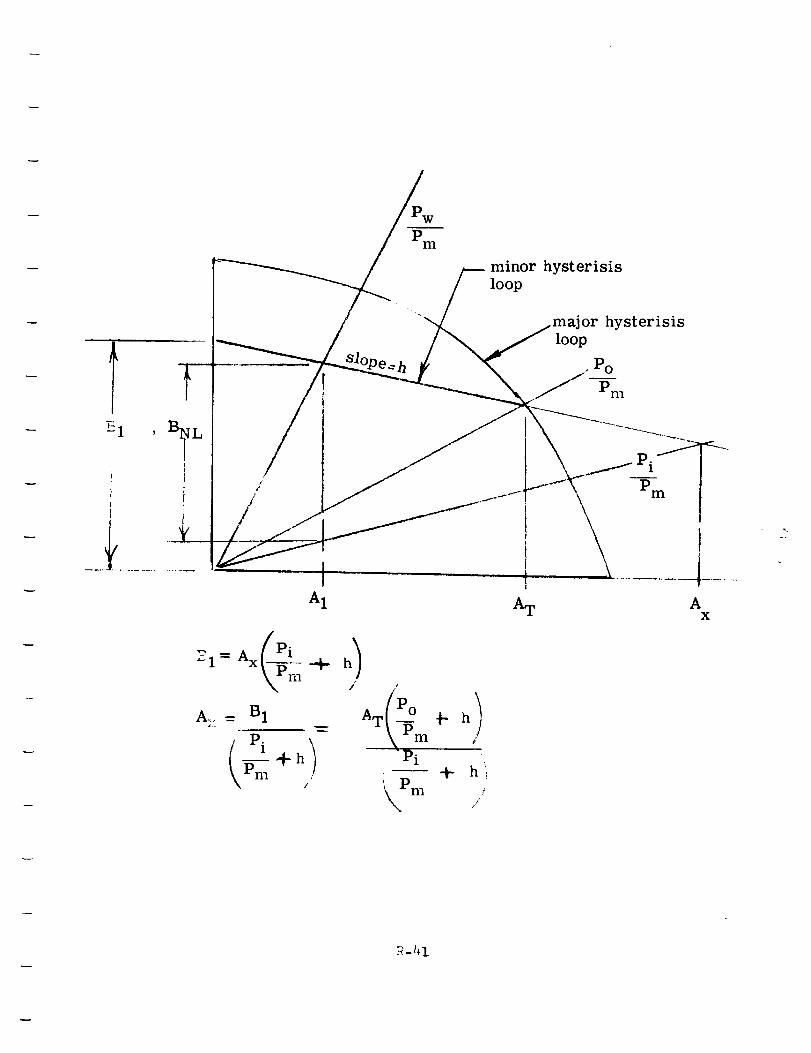
/
A1
_-I_ = Ax P__--_--+- h/l
A..,= B1
_m +hJ
Pm
minor hysterisis
loop
hysterisis
loop
• Po
/Pm
i
iII
IAT
Pi
Pm
AX
/
AT PI_-_111
Pi
'kk,,Pm
b
+hlf
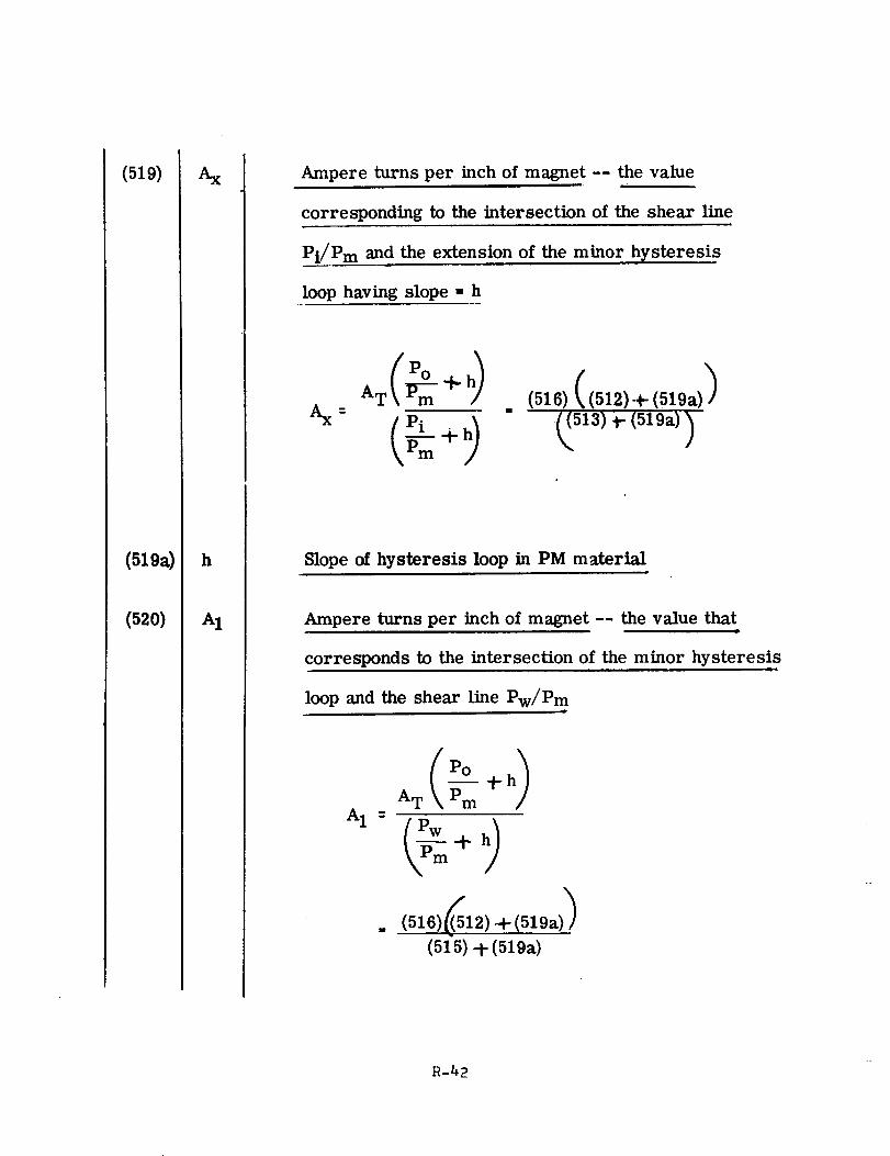
(519)
(519a)
(52o)
h
A1
Ampere turns per inch of magnet -- the value
corresponding to the intersection of the shear line
Pi/Pm and the extension of the minor hysteresis
loop having slope = h
AX --
(516) ((512)+ (519a)_
Slope of hysteresis loop in PM m_terialJ
Ampere turns per inch of magnet -- the value that
corresponds to the intersection of the minor hysteresis
loop and the shear line Pw/Pm
A 1
AT _m t
__-_-+h)
(515) + (519a)
R-42
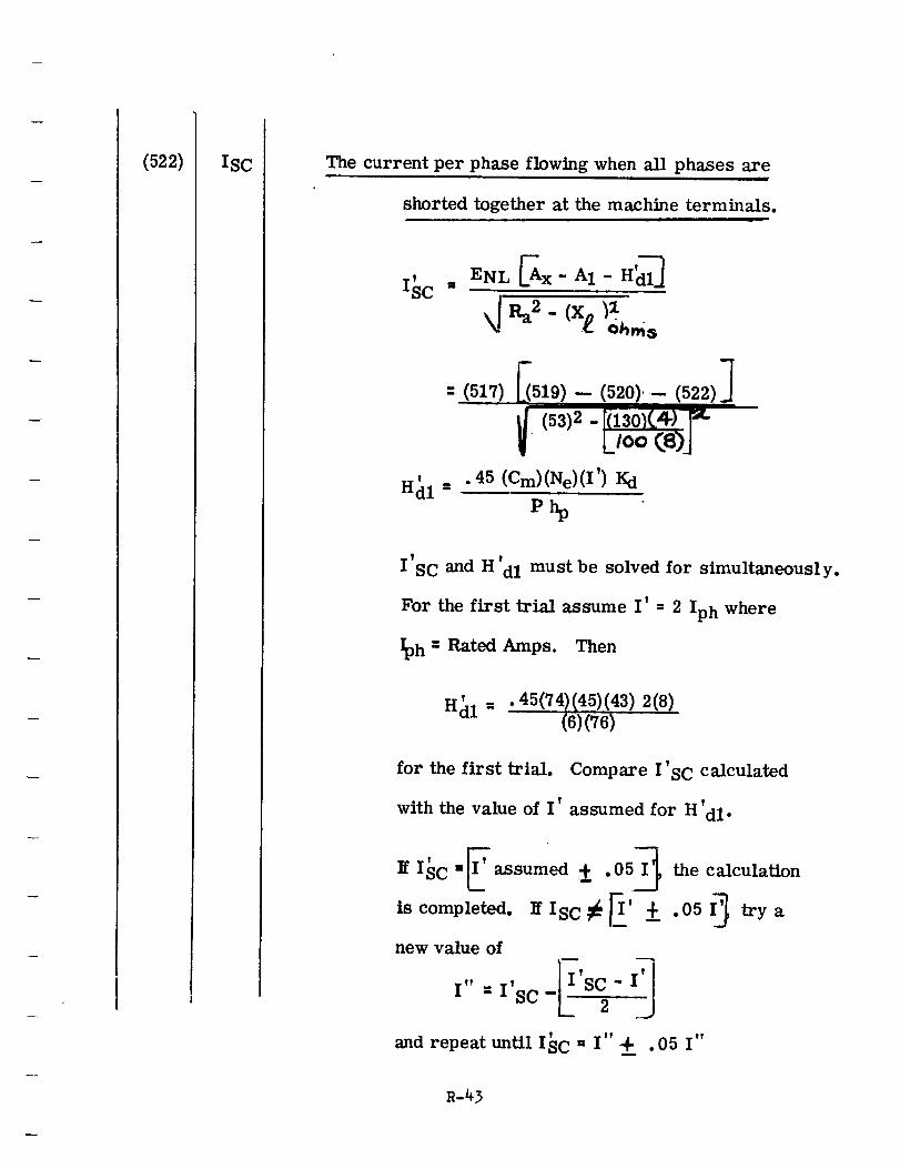
(522) ISC The current per phase flowing when all phases are
shorted together at the machine terminals.
T
ISC
!
Hdl =
ENL 5X-AI- H_I_
F 7: (517)LC519)-<5_.0),-(52_.)J
_. (53)2- R-lsoK4)-_-LIoo(a)J.45 (Cm)(Ne)(I') Kd
P_
I'SC and H'dl must be solved for simultaneously.
For the first trial assume I' - 2 Iph where
_h : Rated Amps. Then
' 45(74)(45)(43) 2(8)Hdl " " (6)(76)
for the first trial.
with the value of I
Compare I'SC calculated
assumed for H'dl.
If ISC = assumed __ . 0 the calculation
is completed. IfIsc_EI' _ .05I_ trya
new value of
I" =I'sc- S "
' I" I"and repeat until ISC = 4- . 05
R-43
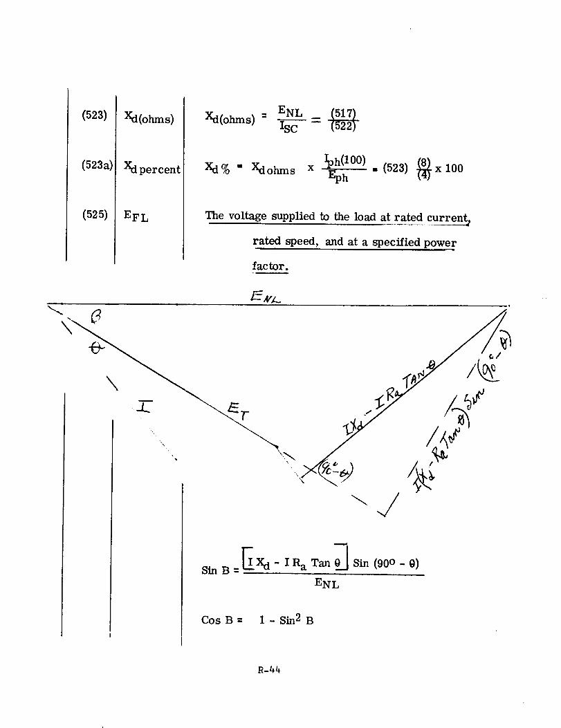
(523)
(523a)
(525)
Xd(ohms)
Xdpercent
EFL
ENLXd(o_s)- =
xd_o" _o_s x _h(l°O) (523)_x looEph "
The voltage supplied to the load at rated current,,
rated speed, and at a specified power
factor.
E X d- IR aTan_Sin (90 o-0)Sin B=
ENL
CosB= 1- Sin 2 B
R-44
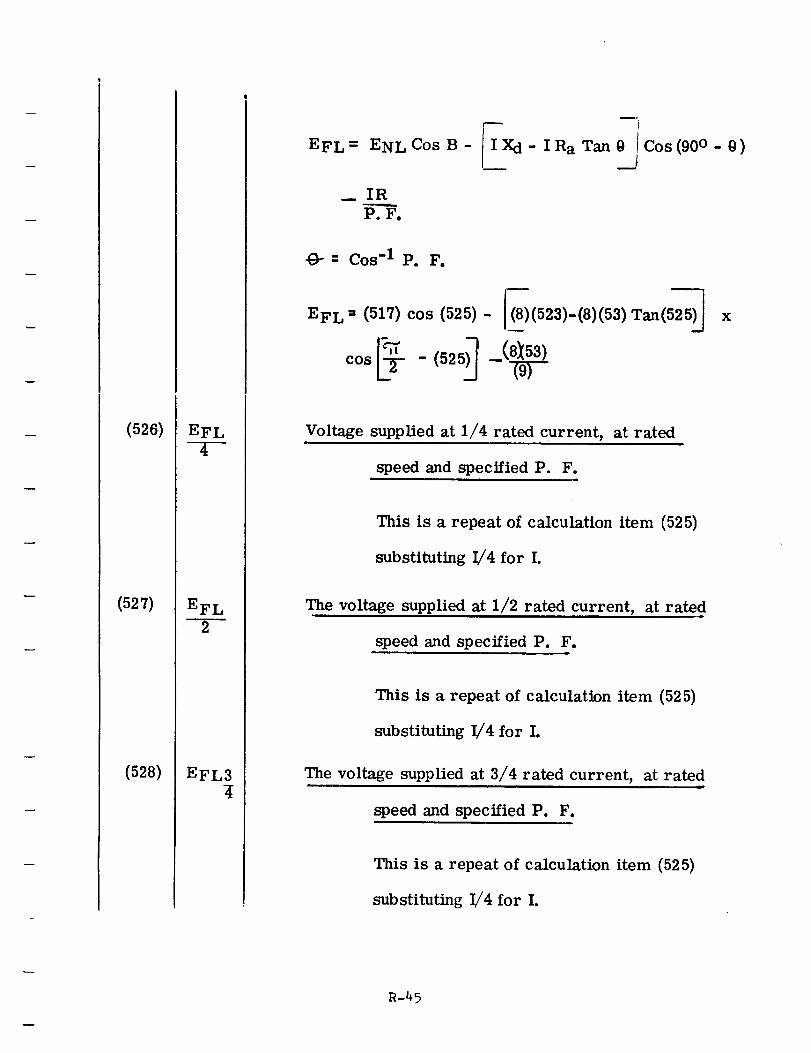
(526)
(527)
(528)
EFL
4
EFL
EFL3
EFL= ENL Cos B -
m_
-Xd- I Ra Tan 0__Cos (90 ° - 0)
__ IR
P.F.
O-= Cos -I P. F.
EFL-- (517) cos (525) - £)(523)-(8)(53)Tan( x
Voltage supplied at 1/4 rated current, at rated
speed and specified P. F.
This is a repeat of calculation item (525)
substituting I/4 for I.
The voltage supplied at 1/2 rated current, at rated
speed and specified P. F.
This is a repeat of calculation item (525)
substituting I/4 for I.
The voltage supplied at 3/4 rated current, at rated
speed and specified P. F.
This is a repeat of calculation item (525)
substituting I/4 for I.
R-45
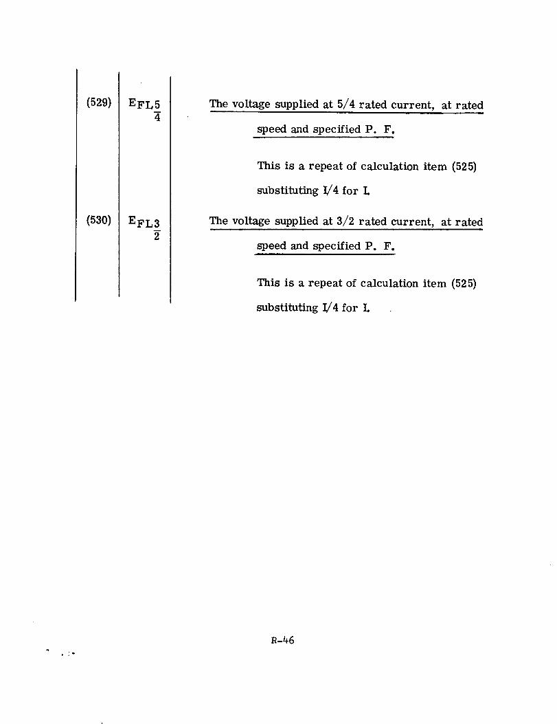
(529)
(53o)
EFL5
4
EFL3
2
The voltage supplied at 5/4 rated current, at ratedi.
speed and specified P. F.
This is a repeat of calculation item (525)
substituting I/4 for L
The voltage supplied at 3/2 rated current, at rated
speed and specified P. F.l
This is a repeat of calculation item (52 5)
substituting !/4 for L
.i-
R-46
!
!
!
i,
i,
EQUIVALENT CIRCUITS __=
,_ i!!__ _
ii
. _i _
[
|
T
|
|
i|'J
|
i
|
Equivalent Circuits
In troduc tion
In the statement of work describing this study, an equivalent circuit is
requested. The description in part reads: "The circuit and parameters
chosen and evaluated should be capable of completely describing both
steady state and transient performance including various overloading
and short-circuit capabilities."
"Parameters for the equivalent circuit are to be derived and evaluated. "
"Transfer functions and time constants are to be derived and evaluated. "
"All applicable reactances are to be derived and evaluated e. g., syn-
chronous, positive and negative sequence, transient and subtransient,
direct and quadrature axes, armature, leakage, armature reaction, etc. "
This section contains a derivation of an equivalent circuit submitted to
satisfy the requirement for a circuit describing steady state and transient
performance. The circuit also describes the performance of the generator
when subjected to unbalanced loading.
The derivation of the equivalent circuit described here is the work
of Liang Liang.
s-1
Overloading, short-circuit capabilities, time constants and reactance
are derived and calculated elsewhere in the study.
The equivalent circuits themselves are on Pages 31, 33, 72 and 73.
The symbols are on Pages 2 and 3. Derivations and explanations are
given step- by- step.
s-2
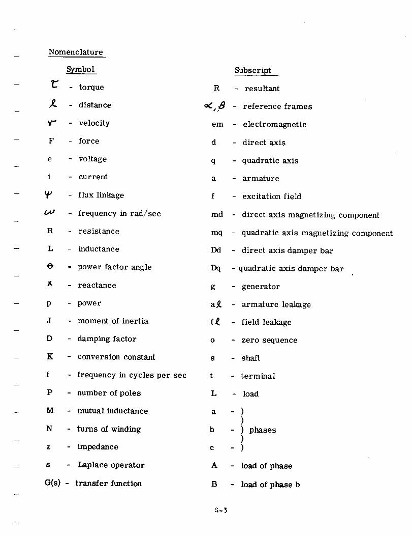
Nomenclature
Symbol
_" - torque
.,_. - distance
Y" - velocity
F - force
e - voltage
i - current
- flux linkage
t_ - frequency in rad/sec
R - resistance
L - inductance
0 - power factor angle
- reactance
p - power
J - moment of inertia
D - damping factor
K - conversion constant
f - frequency in cycles per sec
P - number of poles
M - mutual inductance
N - turns of winding
z - impedance
s - Laplace operator
G(s) - transfer function
R
em
d
q
a
f
md
mq
Dd
Dq
g
O
S
t
L
a
b
e
A
B
3-3
Subscript
- resultant
- reference frames
- electromagnetic
- direct axis
- quadratic axis
- armature
- excitation field
- direct axis magnetizing component
- quadratic axis magnetizing component
- direct axis damper bar
- quadratic axis damper bar
- generator
- armature leakage
- field leakage
- zero sequence
- shaft
- terminal
- load
-))
- ) phases
)-)
- load of phase
- load of phase b
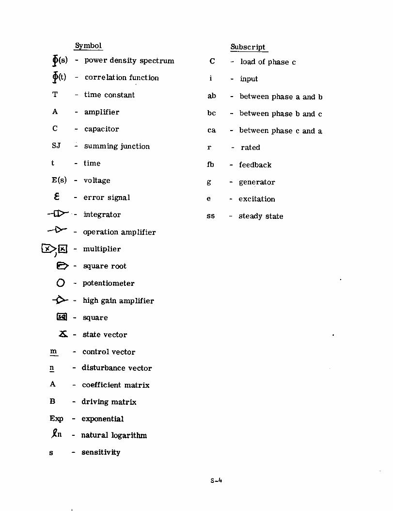
Symbol
_(s) power density spectrumi
_(t) - correlation function
T - time constant
A - amplifier
C - capacitor
SJ - summing junction
t - time
E(s) - voltage
- error signal
-'-ill>--- integrator
- operation amplifier
multiplier
{_ - square root
0 - potentiometer
-_ - high gain amplifier
{_]- square
2_, - state vector
m - control vector
n - disturbance vector
A - coefficient matrix
B - driving matrix
Exp - exponential
j_n - natural logarithm
s - sensitivity
C
i
ab
bc
ca
r
fb
g
e
ss
S-4
Subscript
- load of phase c
- input
- between phase a and b
- between phase b and c
- between phase c and a
- rated
- feedback
- generator
- excitation
- steady state
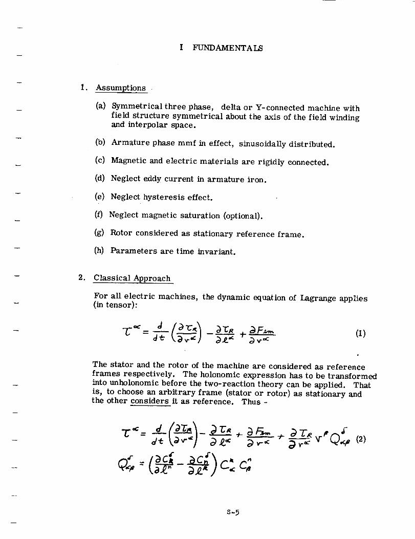
I FUNDAMENTAI_
1. Assumptions.
(a) Symmetrical three phase, delta or Y-connected machine with
field structure symmetrical about the axis of the field windingand interpolar space.
(b) Armature phase mmf in effect, sinusoidally distributed.
(c) Magnetic and electric materials are rigidly connected.
(d) Neglect eddy current in armature iron.
(e) Neglect hysteresis effect.
(f) Neglect magnetic saturation (optional).
(g) Rotor considered as stationary reference frame.
(11) Parameters are time invariant.
2. Classical Approach
For all electric machines, the dynamic equation of Lagrange applies(in tensor):
"L"°¢ 'J _r 4 _'_R _F_,, (i)
The stator and the rotor of the machine are considered as reference
frames respectively. The holonomic expression has to be transformed
into unholonomic before the two-reaction theory can be applied. That
is, to choose an arbitrary frame (stator or rotor) as stationary andthe other considers it as reference. Thus -
s-5
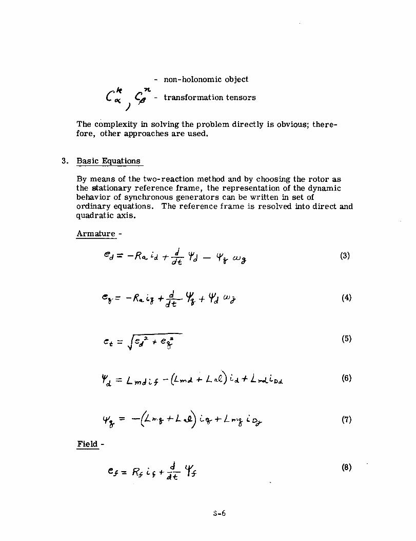
)
- non-holonomic object
- transformation tensors
The complexity in solving the problem directly is obvious; there-
fore, other approaches are used.
3. Basic Equations
By means of the two-reaction method and by choosing the rotor as
the stationary reference frame, the representation of the dynamic
behavior of synchronous generators can be written in set of
ordinary equations. The reference frame is resolved into direct and
quadratic axis.
Armature -
%-= -_.t_ +_-_-_ ÷ Ta _ (4)
(5)
Field -
(7)
(8)
S-5
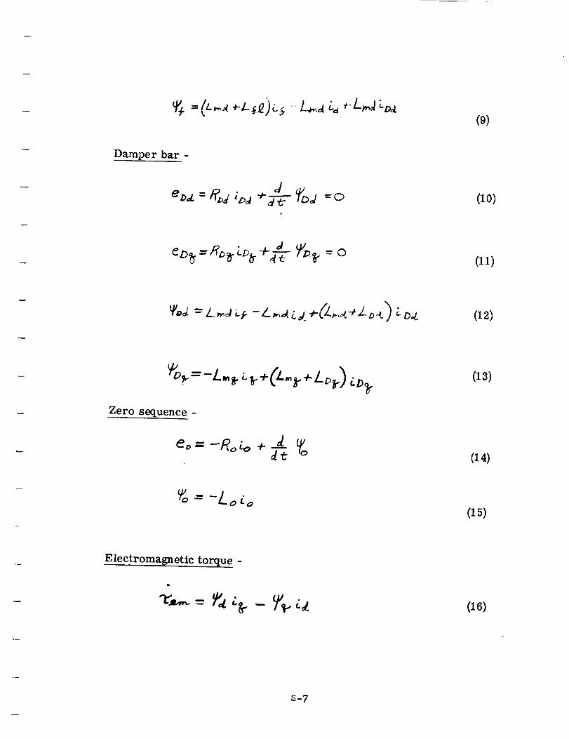
(9)
Damper bar -
m
=0 (lO)
(11)
(12)
Zero sequence -
(13)
eo = -Ro 4, + _--_(I4)
= -Lo to(15)
Electromagnetic torque -
"v..,.,.= _',_':tr (16)
s-7
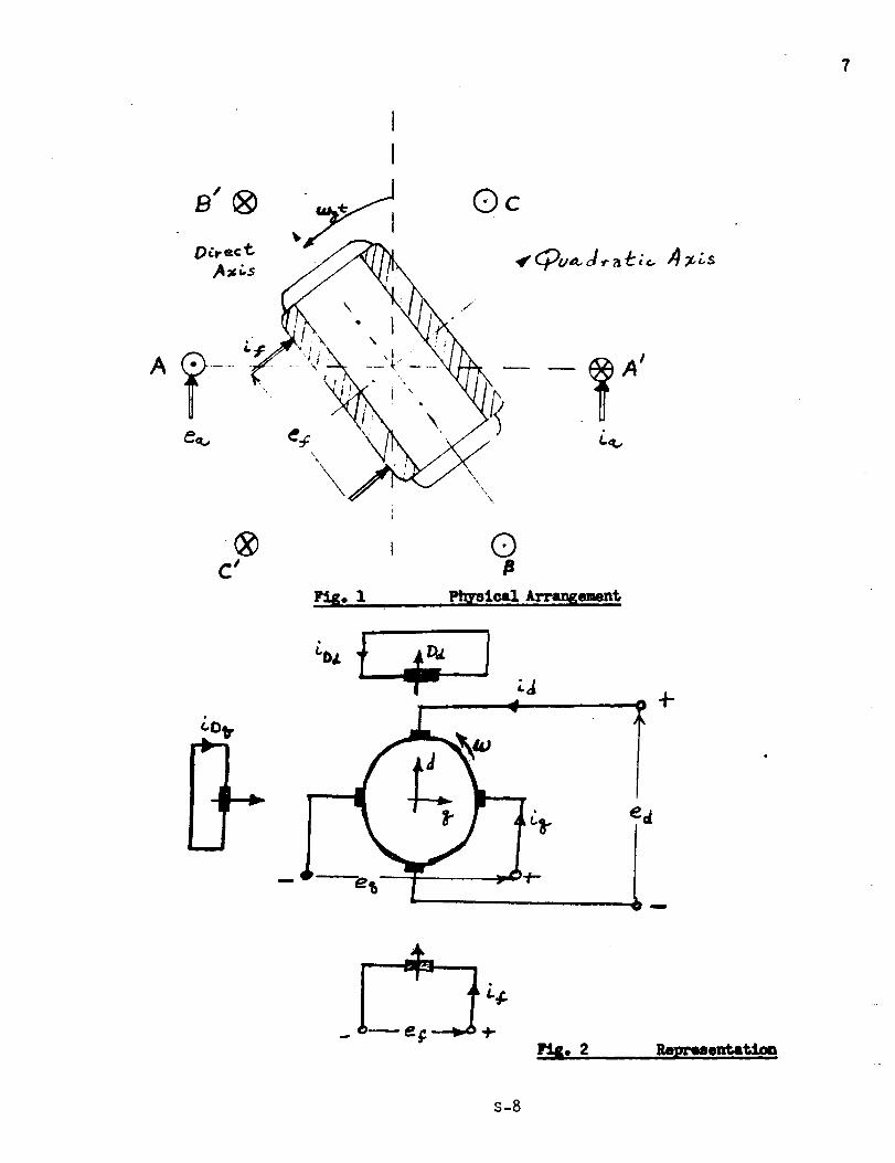
B ® "_ Oc
\
® i 0C' ,a
Repeuentat.'l,_
s-8
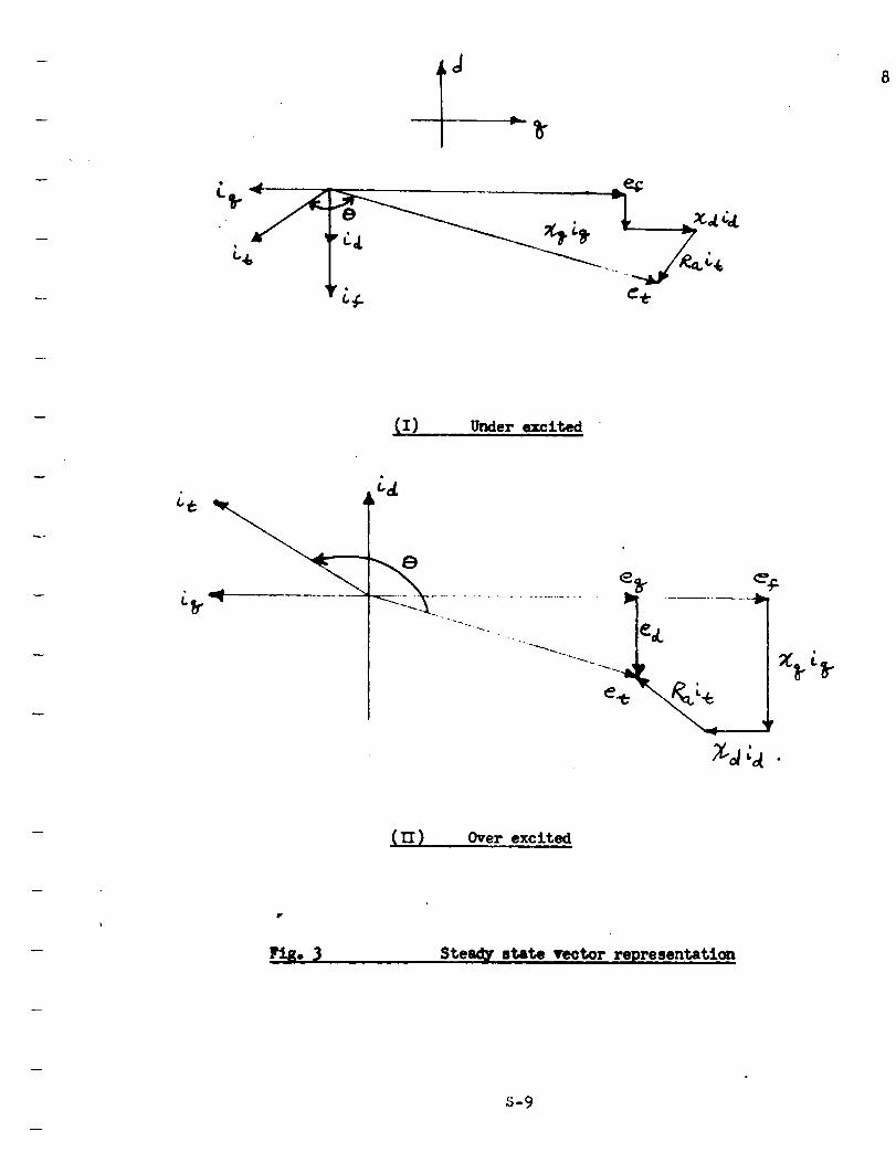
J
_I) Under excited
d
(YI) . Over excited
Steady state vector representation
s-9
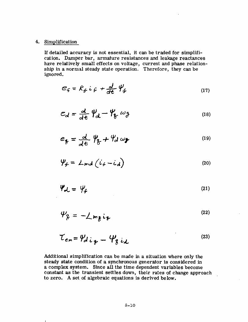
4. Simplification
If detailed accuracy is not essential, it can be traded for simplifi-
cation. Damper bar, armature resistances and leakage reactances
have relatively small effects on voltage, current and phase relation-
ship in a norm_d steady state operation. Therefore, they can be
ignored.
(17)
_e(19)
(20)
_,L "=-_÷ (21)
7_ = -}_._,_ _.(22)
(23)
Additional simplification can be made in a situation where only the
steady state condition of a synchronous generator is considered in
a complex system. Since all the time dependent variables become
constant as the transient settles down, their rates of change approach
to zero. A set of algebraic equations is derived below.
S-IO
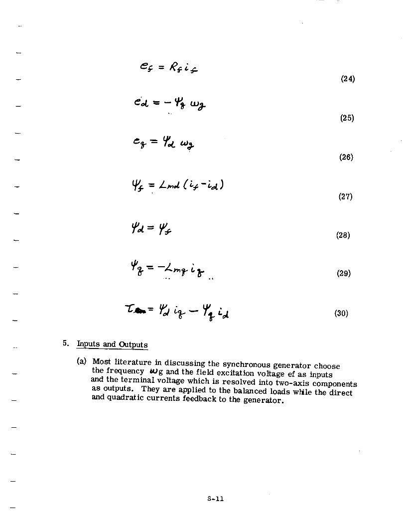
(24)
¢_. = _ % _-(25)
(26)
(27)
(28)
(29)
(30)
5. Inputs and Outputs
(a) Most literature in discussing the synchronous generator choose
the frequency tug and the field excitation voltage ef as inputs
and the terminal voltage which is resolved into two-axis components
as outputs. They are applied to the balanced loads while the directand quadratic currents feedback to the generator.
S-II
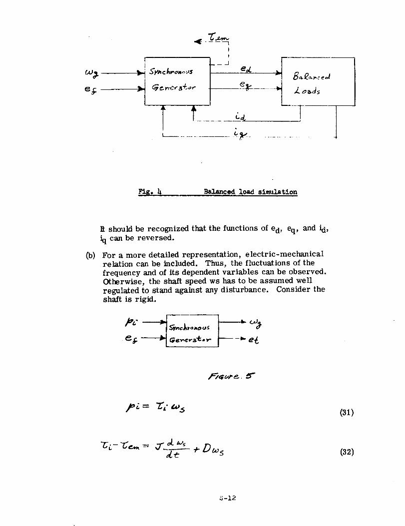
r
r
I
I!
___ ._[
e_
e_ .....
b Z _,as
Fig. h Balanced load simulation
_)
R should be recognized that the functions of ed, eq, and id,
iq can be reversed.
For a more detailed representation, electric-mechanical
relation can be included. Thus, the fluctuations of the
frequency and of its dependent variables can be observed.
Otherwise, the shaft speed ws has to be assumed well
regulated to stand against any disturbance. Consider the
shaft is rigid.
[.
2,Z= Z'( _,_(31)
-ci-'c'_- ,7"__' + D_ s4e (32)
S-12
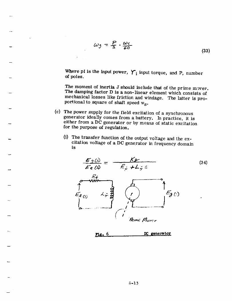
(33)
(c)
Where pi is the input power, _'i input torque, and P, numberof poles.
The moment of inertia J should include that of the prime mover.The damping factor D is a non-linear element which consists of
mechanical losses like friction and windage. The latter is pro-
portional to square of shaft speed Ws°
The power supply for the field excitation of a synchronous
generator ideally comes from a battery. In practice, it iseither from a DC generator or by means of static excitationfor the purpose of regulation.
(i) The transfer function of the output voltage and the ex-
citation voltage of a DC generator in frequency domainis
. ca _
ic_ ...... _o
:_,,,,e /_ov,: r
Io
(34)
DC generator
S-13
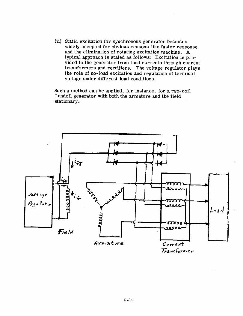
(ii) Static excitation for synchronous generator becomes
widely accepted for obvious reasons like faster response
and the elimination of rotating excitation machine. A
typical approach is stated as follows: Excitation is pro-
vided to the generator from load currents through current
transformers and rectifiers. The voltage regulator plays
the role of no-load excitation and regulation of terminal
voltage under different load conditions.
Such a method can be applied, for instance, for a two-coil
IJ.mdell generator with both the armature and the field
stationary.
II I I II I
S-14
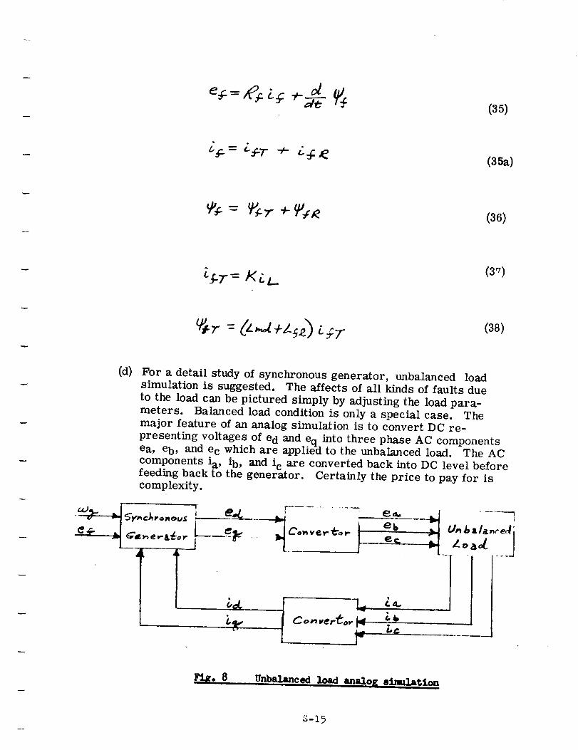
(35)
(35a)
(36)
(3'7)
(38)
(d) For a detail study of synchronous generator, unbalanced load
simulation is suggested. The affects of all kinds of faults due
to the load can be pictured simply by adjusting the load para-meters. Balanced load condition is only a special case. The
major feature of an analog simulation is to convert DC re-
presenting voltages of e d and eq into three phase AC componentsea, eb, and e c which are applied to the unbalanced load. The AC
components ia, ib, and i c are converted back into DC level before
feeding back to the generator. Certainly the price to pay for iscomplexity.
='L
F .....- e_.. . I .......
f --k II Co,_.erto. _ ,
Pie. 8Unbalanced !_,__d an__o K e4.,_=t_4 _-
S-15
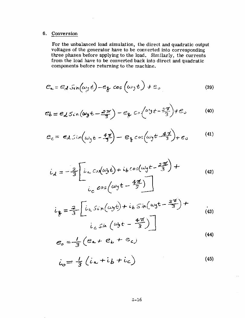
6. Conversion
For the unbalanced load simulation, the direct and quadratic output
voltages of the generator have to be converted into corresponding
three phases before applying to the load. Similarly, the currents
from the load have to be converted back into direct and quadraticcomponents before returning to the machine.
(40)
(41)
(42)
= 3 z (43)
(44)
(45)
S-16
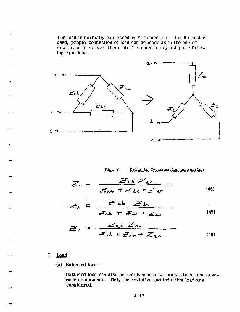
The load is normally expressed in Y-connection. If delta load is
used, proper connection of load can be made as in the analog
simulation or convert them into Y-connection by using the follow-
ing equations:
C_
L
I Z,.
I
\,
1
Fig. 9 Delta to Y-connection conversion
£'_-b=
_7_c _bc
----=',_A+ Z&c + Z,z
(46)
(47)
(48)
• Load
(a) Balanced load -
Balanced load can also be resolved into two-axis, direct and quad-ratic components. Only the resistive and inductive load areconsidered.
S-17
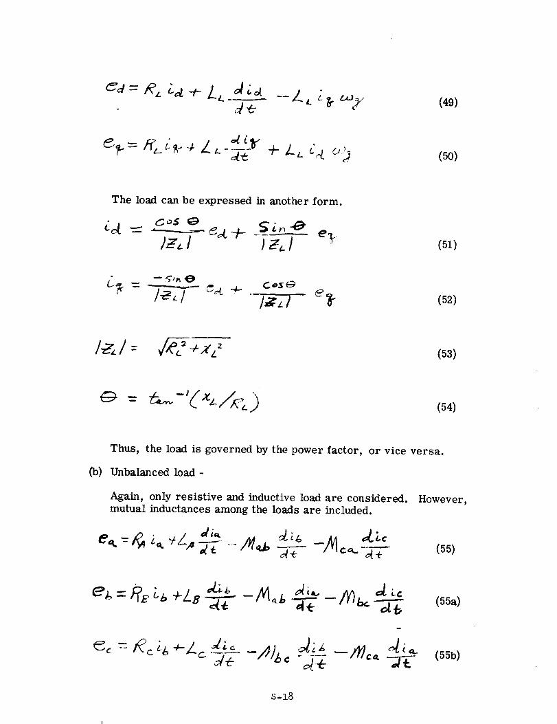
cd = R_ _a 4-LL_(49)
_ • _y(50)
The load can be expressed in another form.
(51)
CoS e:_
...../._. / _ (52)
V_'_ + X Lz (53)
(54)
0_)
Thus, the load is governed by the power factor, or vice versa.
Unbalanced load-
Again, only resistive and inductive load are considered.
mutual inductances among the loads are included.However,
(55)
e _,= i_E Lt, +Le A_----.-L*- (55a)
(55b)
S-18
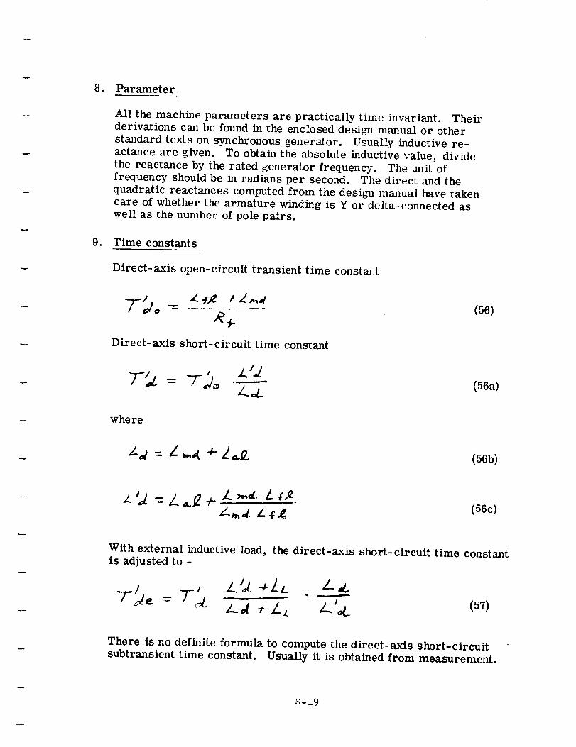
8. Parameter
All the machine parameters are practically time invariant. Their
derivations can be found in the enclosed design manual or other
standard texts on synchronous generator. Usually inductive re-
actance are given. To obtain the absolute inductive value, dividethe reactance by the rated generator frequency. The unit of
frequency should be in radians per second. The direct and the
quadratic reactances computed from the design manual have taken
care of whether the armature winding is Y or delta-connected aswell as the number of pole pairs.
9. Time constants
Direct-axis open-circuit transient time consta_,t
Dire ct- axis short- circuit time constant
where
(56)
(56a)
(56b)
z - L J * :....Z-L¢ (56c)
With external inductive load, the direct-axis short-circuit time constantis adjusted to -
There is no definite formula to compute the direct-axis short-circuit
subtransient time constant. Usually it is obtained from measurement.
S-19
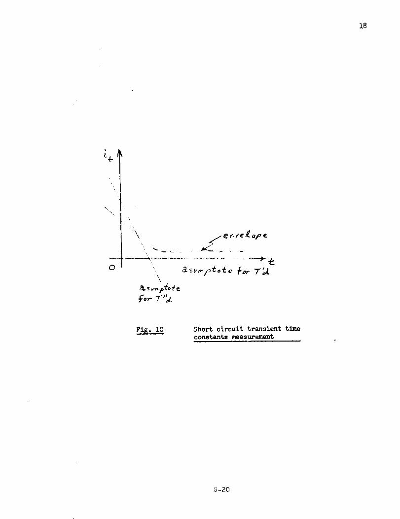
18
0
;\
..... -_ ........................ __>.?::
\
fo,.- r"_.
Fi_.lO Short circuit transient time
constants measurement
S-20
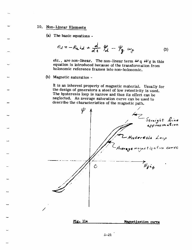
10. Non- Linear Elements
(a) The basic equations =
(3)
etc., are non-linear. The non-linear term _ q _J,'g in thisequation is introduced because of the transformation from
holonomic reference frames into non-holonomic.
(b) Magnetic saturation -
It is an inherent property of magnetic material. Usually for
the design of generators a steel of low retentivity is used.The hysteresis loop is narrow and thus its effect can be
neglected. An average saturation curve can be used to
describe the characteristics of the magnetic path.
/
| S
G %:.. f. "
/
Ha_netization curve
S-21
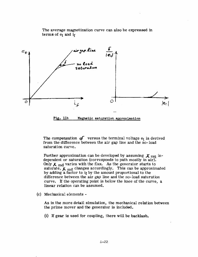
The average magnetization curve can also be expressed in
terms of e t and if
d)
g
leJ
C_
Fig. llb Magnetic saturation approximation
%.T
)e I
The compensation Or" versus the terminal voltage e t is derived
from the difference between the air gap line and the no-loadsaturation curve.
Further approximation can be developed by assuming ._ mq in-dependent or saturation (corresponds to path mostly in air).
Only _ md varies with the flux. As the generator starts to
saturate, _ md changes accordingly. This can be approximatedby adding a factor to if by the amount proportional to the
difference between the air gap line and the no-load saturation
curve. If the operating point is below the knee of the curve, alinear relation can be assumed.
(c) Mechanical elements -
As in the more detail simulation, the mechanical relation between
the prime mover and the generator is included.
(i) If gear is used for coupling, there will be backlash.
S-22
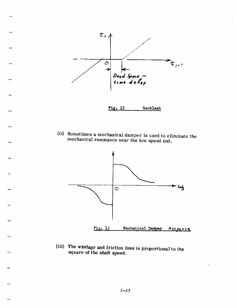
C)
///
,//
/
/
J
Fig. 12 Backlash
(ii) Sometimes a mechanical damper is used to eliminate the
mechanical resonance near the low speed end.
0
Fi_. i_ Mechanical Damper t_¢spoeS__
(iii) The windage and friction loss is proportional to thesquare of the shaft speed.
S-23
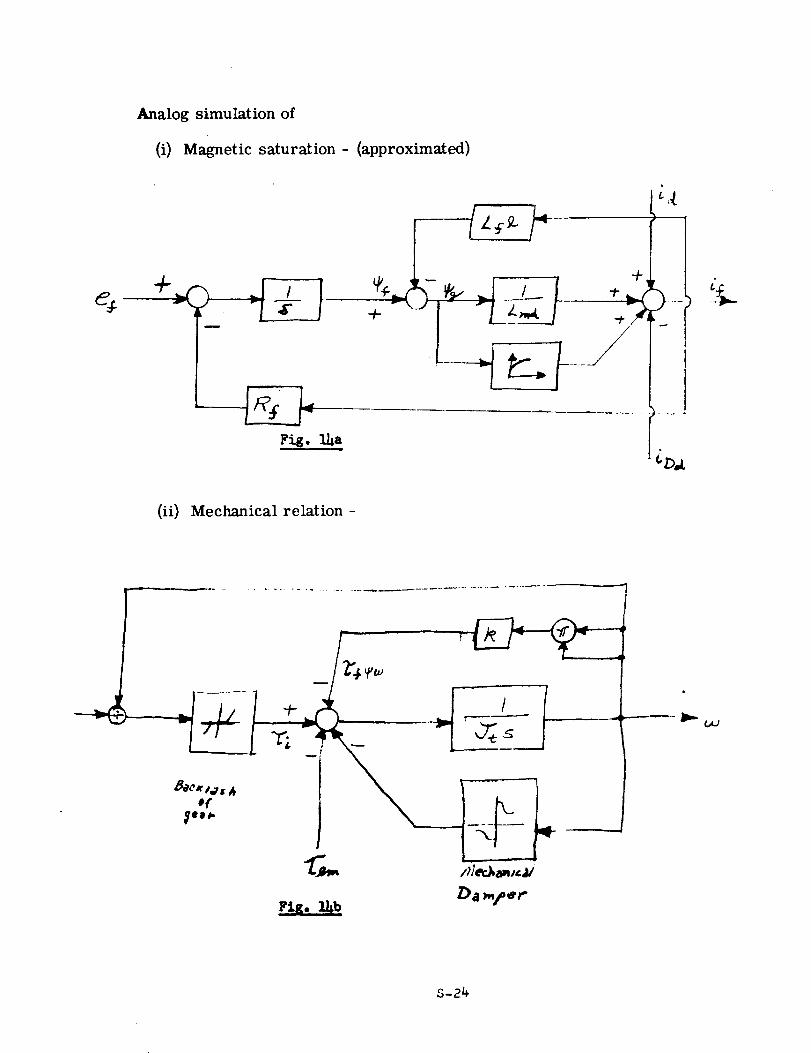
Analog simulation of
(i) Magnetic saturation - (approximated)
(ii) Mechanical relation -
,¢fgl _,
Fig. ll,bDa refer
013
S-24
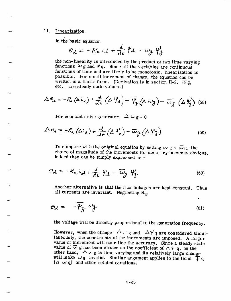
11. IAnearization
In the basic equation
ea. = -R._
the non-linearity is introduced by the product oi two time varying
functions co g and _ q. Since all the variables are continuous
functions of time and are likely to be monotonic, linearization is
possible. For small increment of change, the equation can be
written in a linear form. (Derivation is in section H-2. _g,etc., are steady state values.)
For constant drive generator, ,4 uJ g : 0
(59)
To compare with the original equation by setting I._' g - _ g, the
choice of magnitude of the increments for accuracy becomes obvious.
Indeed they can be simply expressed as -
Another alternative is that the flux linkages are kept constant. Thus
all currents are invariant. Neglecting Ra,
(61)
the voltage will be directly proportional to the generation frequency.
However, when the change Z_ _ g and ,A_'q are considered simul-
taneously, the constraints of the increments are imposed. A larger
value of increment will sacrifice the accuracy. Since a steady state
value of _ g has been chosen as the coefficient of A _Y q, on the
other hand, .Z_ _,_ g is time varying and its relatively large change
will make u_ 8 invalid. Similar argument applies to the term _ff q(/A t_ q) and other related equations.
S-25
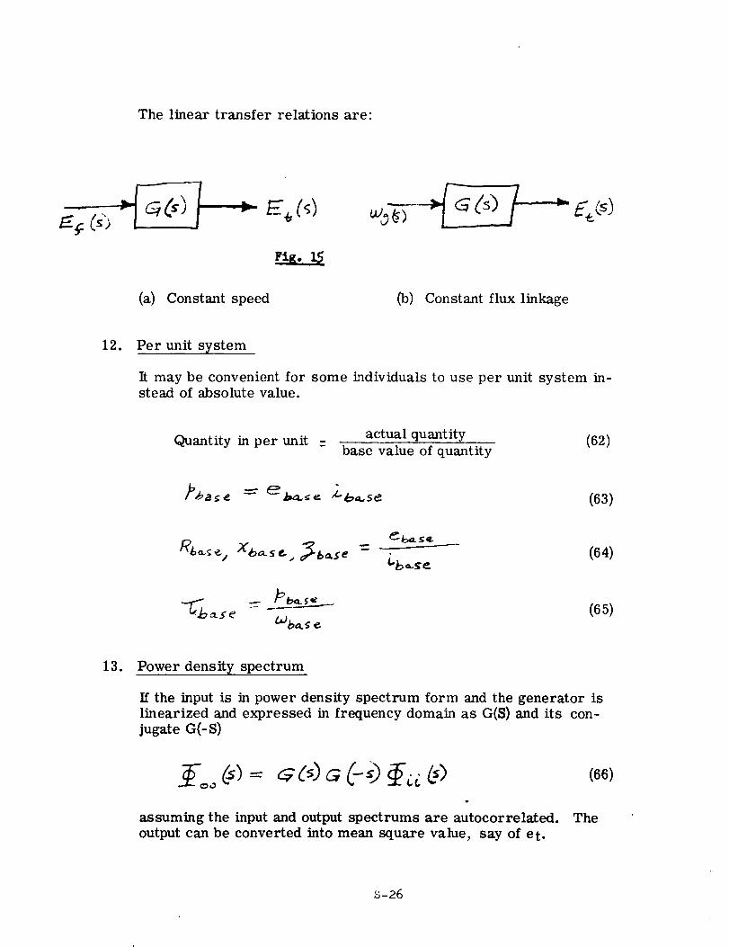
The linear transfer relations are:
Fi_.
(a) Constant speed (b) Constant flux linkage
12. Per unit system
It may be convenient for some individuals to use per unit system in-stead of absolute value.
Quantity in per unit : actual quantity (62)base value of quantity
13. Power density spectrum
If the input is in power density spectrum form and the generator islinearized and expressed in frequency domain as G($) and its con-
jugate G(-S)
t
assuming the input and output spectrums are autocorrelated. The
output can be converted into mean square value, say of et.
S-26
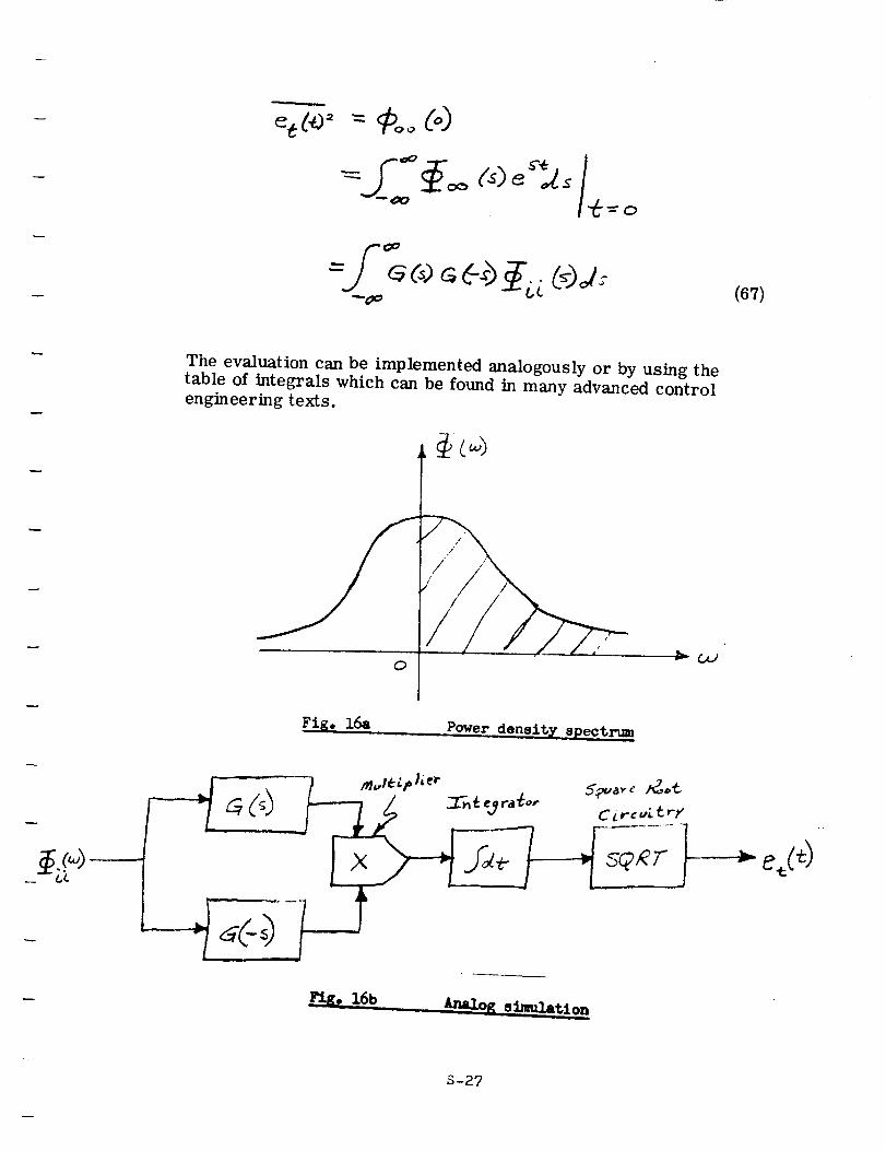
(67)
The evaluation can be implemented analogously or by using thetable of integrals which can be found in many advanced controlengineering texts.
0
Fig. 16,1 Power density spect_._..
S-27
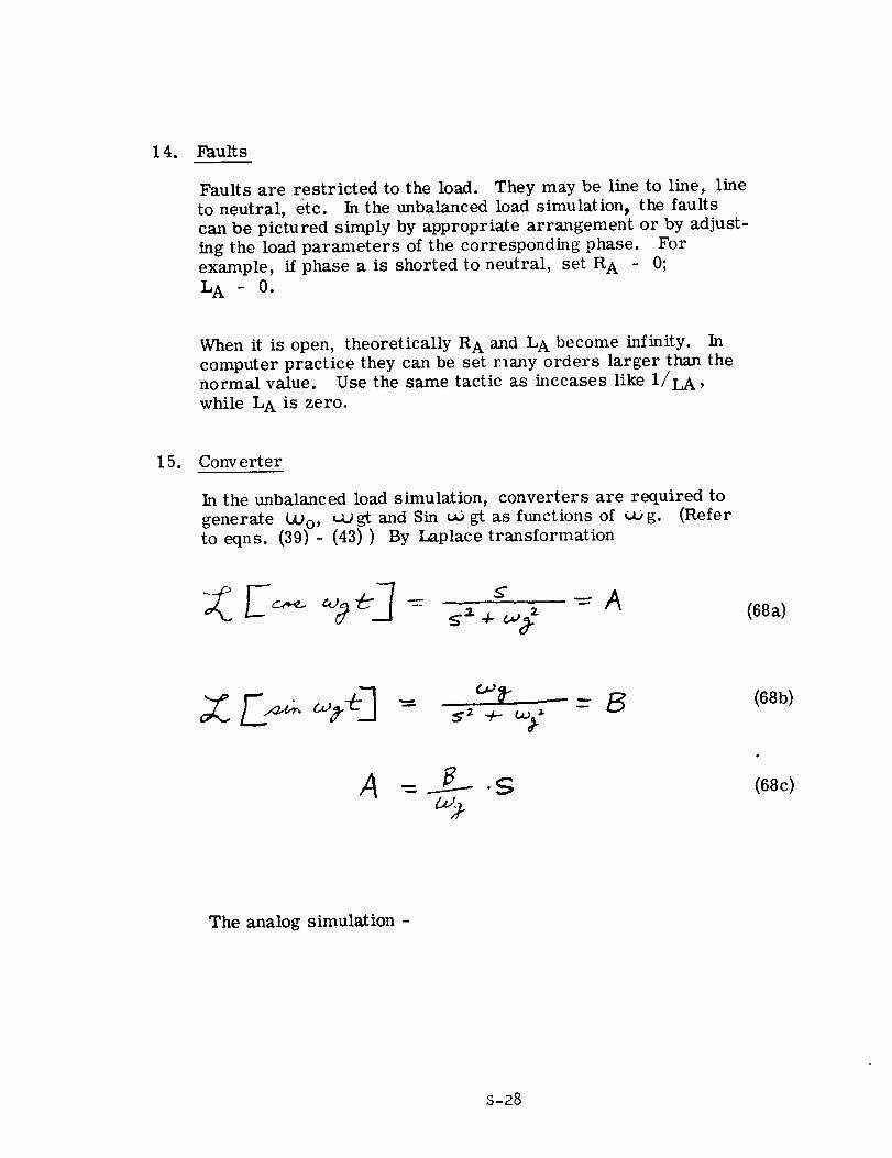
14. Faults
Faults are restricted to the load. They may be line to line, line
to neutral, etc. In the unbalanced load simulation_ the faults
can be pictured simply by appropriate arrangement or by adjust-
ing the load parameters of the corresponding phase. For
example, if phase a is shorted to neutral, set R A - 0;
L A - 0.
When it is open, theoretically R A and L A become infinity. In
computer practice they can be set r_any orders larger than thenormal value. Use the same tactic as inccases like 1/LA,
while L A is zero.
15. Converter
In the unbalanced load simulation, converters are required to
generate _Jo, caj gt and Sin uo gt as functions of c_j g. (Refer
to eqns. (39) - (43)) By Laplace transformation
(68a)
(68b)
(68c)
The analog simulation -
s-28
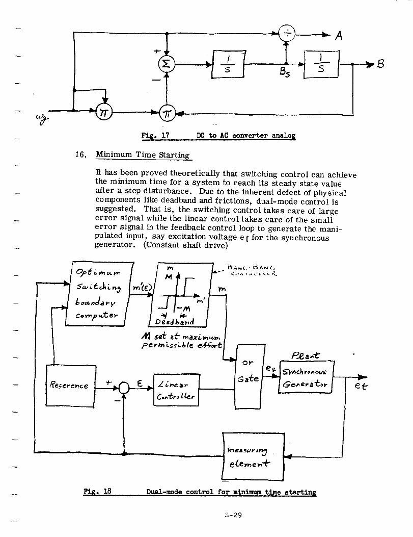
I
L
FI_. 17 DC to AC converter analo_
16. Minimum Time Starting
It has been proved theoretically that switching control can achieve
the minimum time for a system to reach its steady state value
after a step disturbance. Due to the inherent defect of physicalcomponents like deadband and frictions, dual-mode control is
suggested. That is, the switching control takes care of largeerror signal while the linear control takes care of the small
error signal in the feedback control loop to generate the mani-
pulated input, say excitation voltage e f for the synchronousgenerator. (Constant shaft drive)
J ll!Fig. 18
,im
..._easur,_
e (.er,,e,-,'t_
Du_-mode ,control for minimum time 8tartin R
S-29
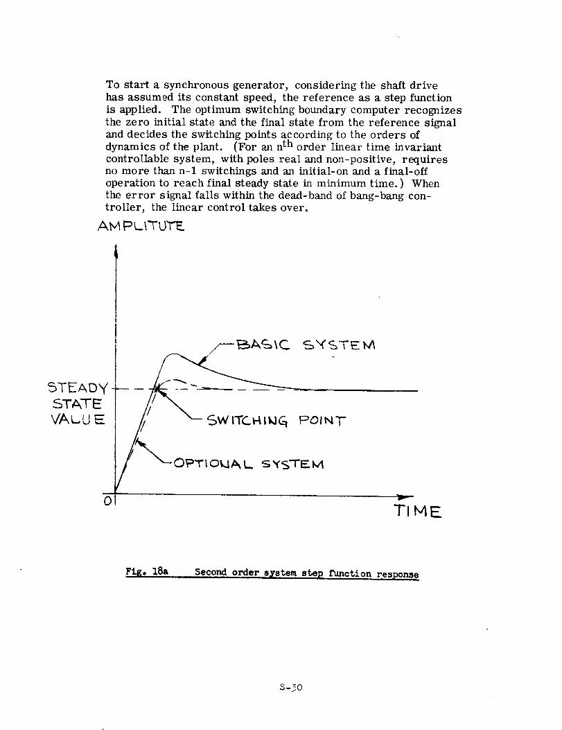
To start a synchronous generator, considering the shaft drive
has assumed its constant speed, the reference as a step function
is applied. The optimum switching boundary computer recognizes
the zero initial state and the final state from the reference signal
and decides the switching points according to the orders of
dynamics of the plant. (For an n th order linear time invariant
controllable system, with poles real and non-positive, requires
no more than n-1 switchings and an initial-on and a final-off
operation to reach final steady state in minimum time.) When
the error signal falls within the dead-band of bang-bang con-
troller, the linear control takes over.
AM PL_TUTE
STEADy
0
/--_A_S \C_ SX_STE _
otNT
/_-OPTIOMAL,. SXSTEM
TI IVlE
Fig. 18a Second order s_stem step function response
S-30
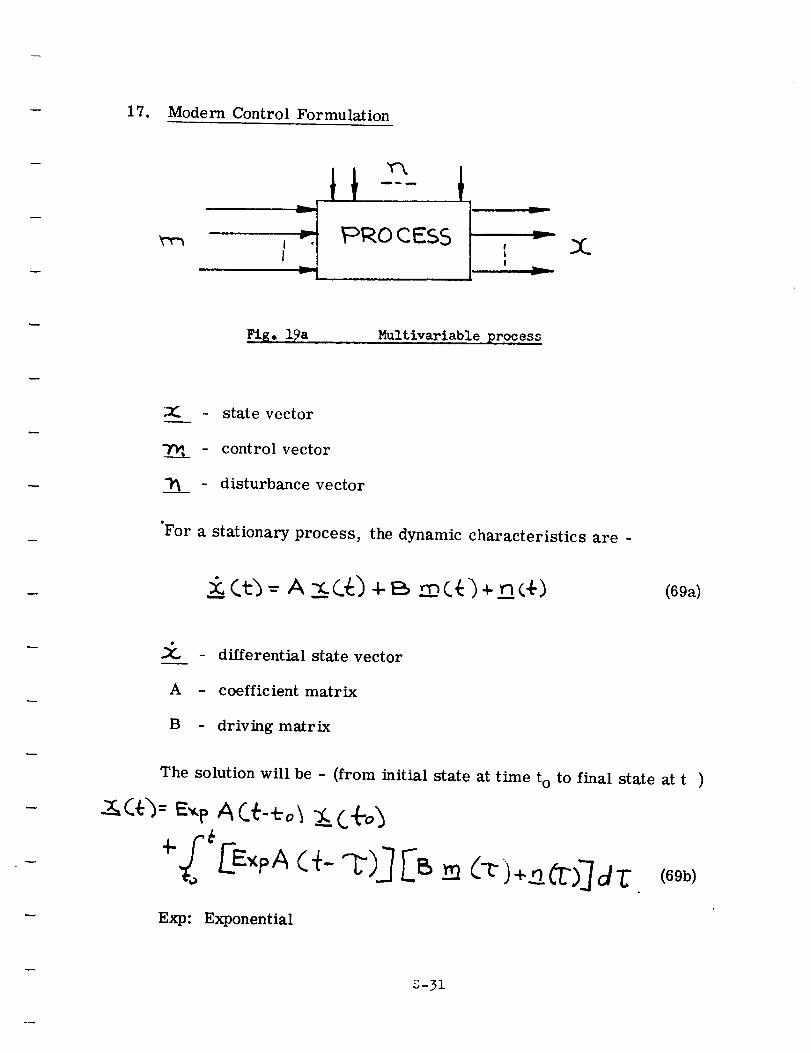
17. Modern Control Formulation
ti
t_ PROCESS
v
I
i
I
Fig. 19a Multivariable process
:Z: - state vector
- control vector
- disturbance vector
"For a stationary process, the dynamic characteristics are -
(69a)
:_ - differential state vector
A - coefficient matrix
B - driving matrix
The solution will be - (from initial state at time t o to final state at t )
CO)=E_e A C_--eo_,_ (.÷o_
Exp: Exponential
S-31
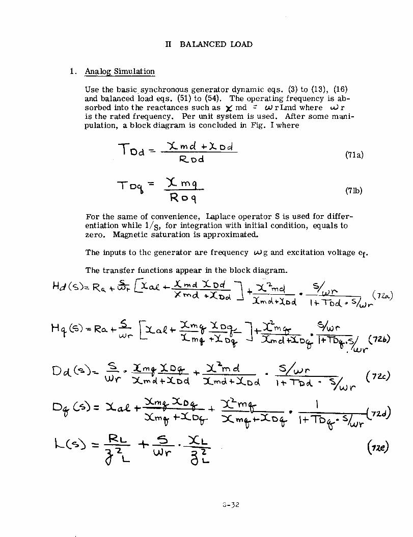
11 BALANCED LOAD
1. Analog Simulation
Use the basic synchronous generator dynamic eqs. (3) to (13), (16)
and balanced load eqs. (51) to (54). The operating frequency is ab-
sorbed into the reactances such as _: md = UJ rLmd where _ r
is the rated frequency. Per unit system is used. After some mani-
pulation, a block diagram is concluded in Fig. I where
TIDa - ")C.md _-_-o_R_od (71a)
Roq(71b)
For the same of convenience, Laplace operator S is used for differ-
entiation while l/s, for integration with initial condition, equals to
zero. Magnetic saturation is approximated.
The inputs to the generator are frequency vO g and excitation voltage ef.
The transfer functions appear in the block diagram.
_...br,._.,_
S-32
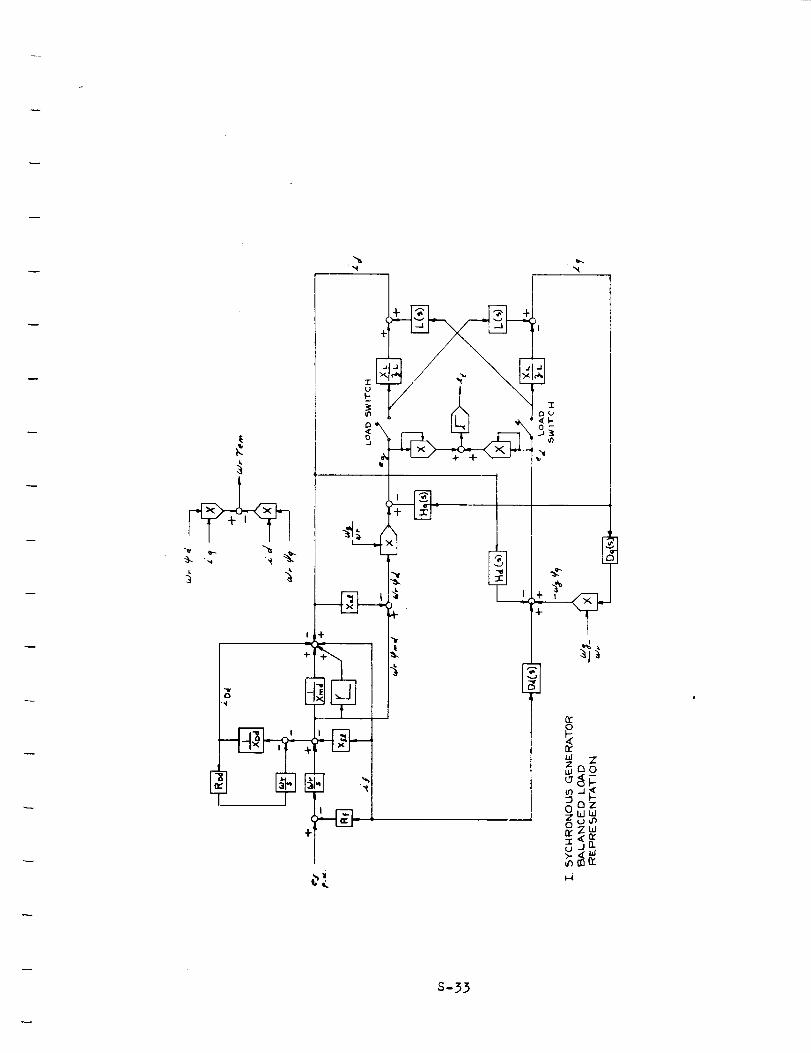
i +
_hI
E_FF
Z
DZWt_
S-33
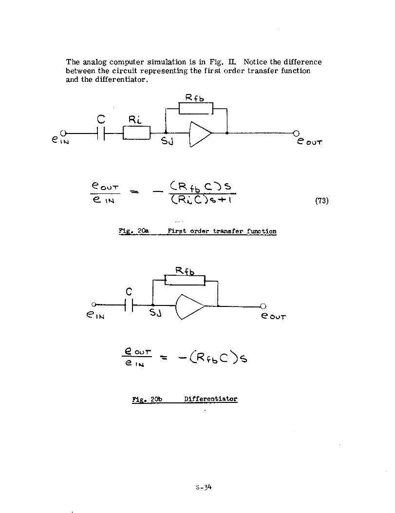
The analog computer simulation is in Fig. II. Notice the difference
between the circuit representing the first order transfer function
and the differentiator.
0
C_ ÷b c'b
(73)
_I_. 2oa
J_
First order transfer function
©
CIIII
Fig° 20b Differentiator
S-34
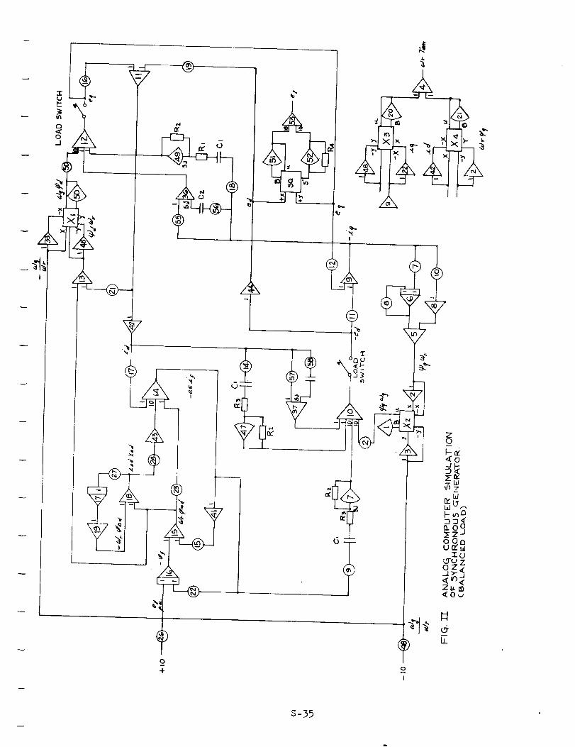
I
0
o
4.
b/LT.,Ld
_-_C_
.oooOc}
•-rUL.9"uZ
c_
0
I
S-35
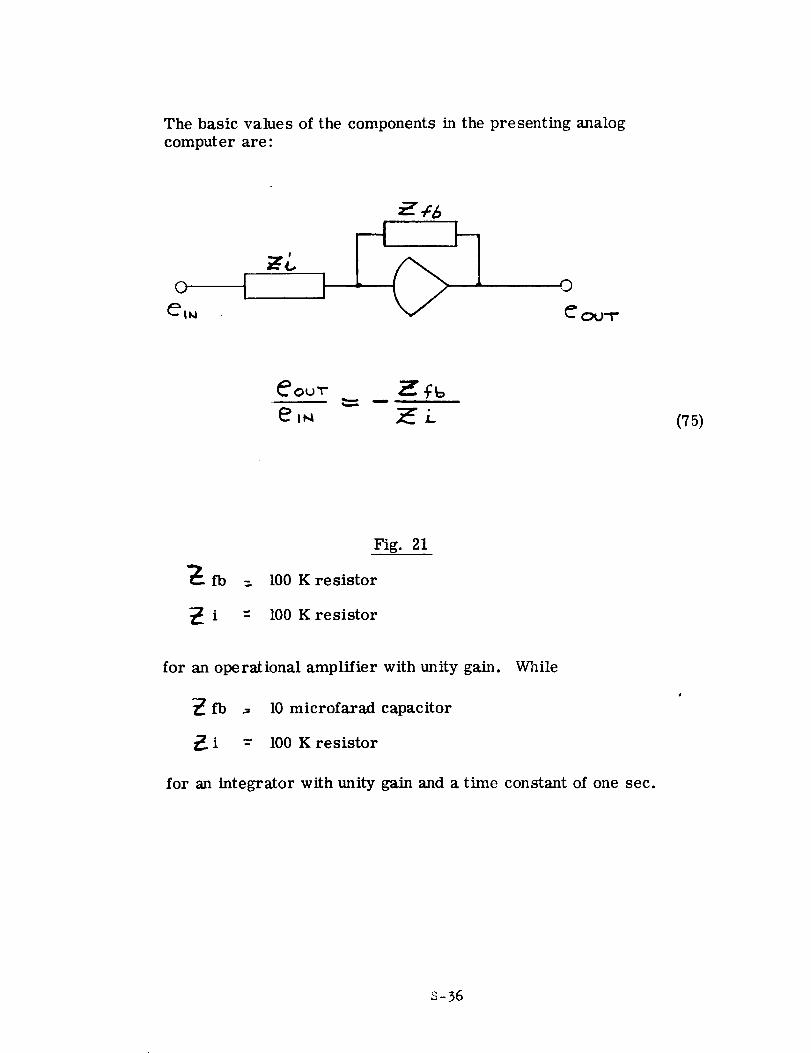
The basic values of the components in the presenting analog
computer are:
(75)
Fig. 21
fb = 100 K resistor
i = 100 K resistor
for an operational amplifier with unity gain.
fb _ 10 microfarad capacitor
i -- 100 K resistor
While
for an integrator with unity gain and a time constant of one sec.
S-36
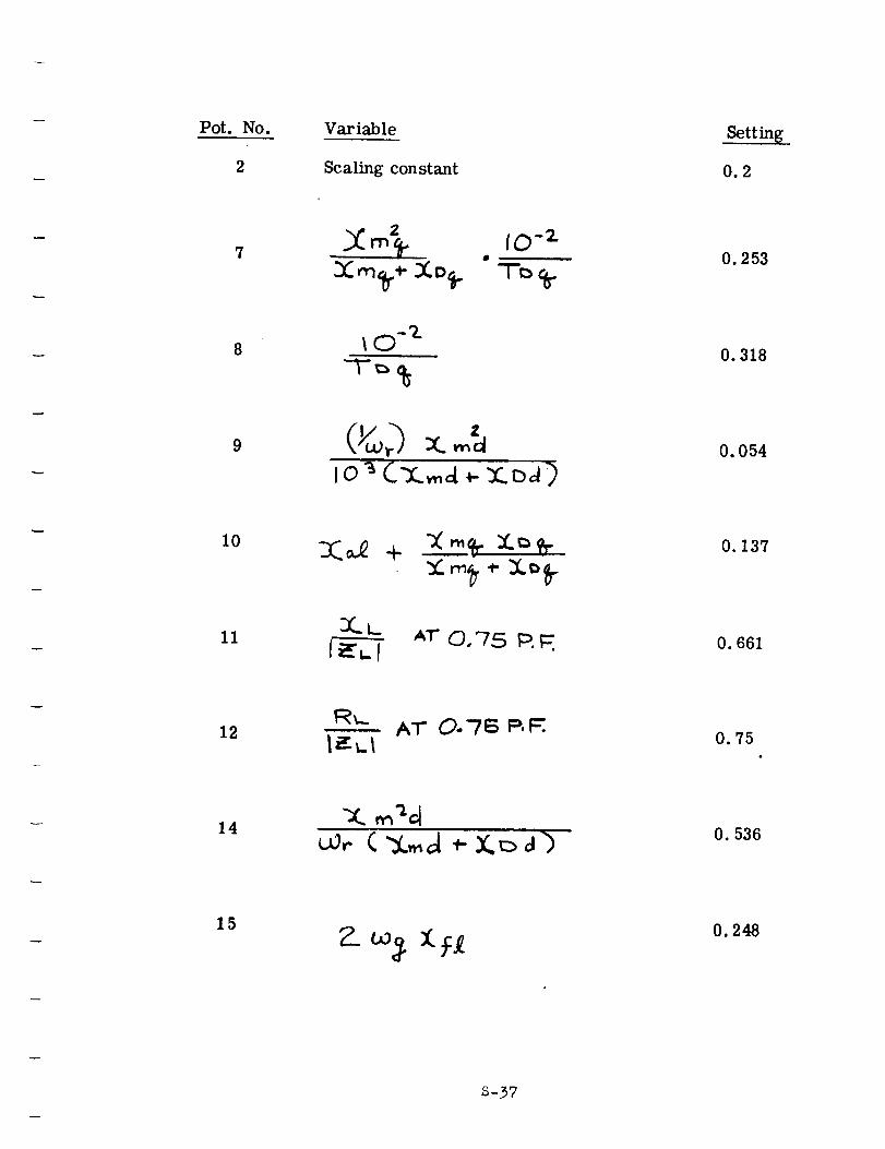
Pot. NO.
2
Variable
Scaling constant
Setting
0.2
7
9
m_ , IO -z
X:m_r-,-XD_. T_ %.
Io "_CT,.,_a _-Y_..:}_)
O. 253
0.318
O. 054
I0
II Ar O,75 p._
O. 137
O. 661
12 AT O.7S P._.0.75
14 O. 536
15 O. 248
S-37
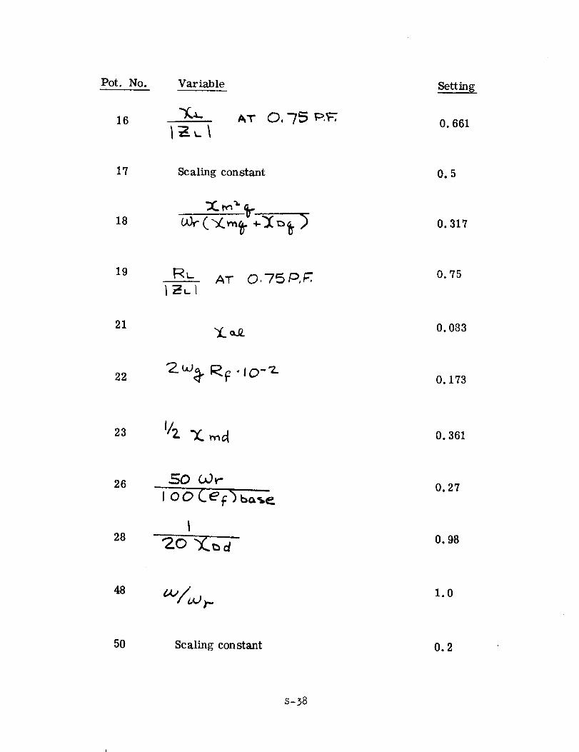
Pot. No. VariableSetting
16 ,_"r O,-/'5 p.'_,,0. 661
17 Scaling constant 0.5
18 0.317
19 RL AT O, 75 ,°,_ 0.75
21"_(._
O. 083
22 '2._ _-F" ao-'Z0.173
23 0.361
26 -_0 03,-
i oo CeFb ba_. _0.27
28 0.98
48 1.0
5O Scaling constant 0.2
S-38
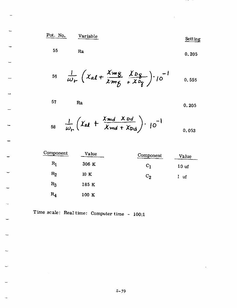
Pot. No. Variable
55 Ra
56* "1o
z-,,, b _.,zt,_/
57 p_
58/x.i t .
Setting
0.205
O. 555
0.205
O. 053
Component Value
R1 306 K
R2 10 K
R3 185 K
R4 100 K
Time scale: Real time: Computer time
Component
CI
C 2
100:1
Value
10uf
1 uf
S-39
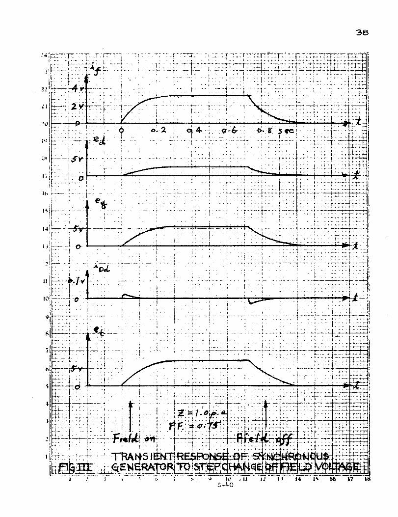
38
+- - _..... 4-_ ....... + ..... _ ...... _-Li--, ....... -1-*-----_-_-_- --=-# ...... Il.... L--_+:-_-,--_..+_1
: - _' ......... ,i- .... * ....... '.... 1" _--t -- , ......... o._ -_-s-l--F, + +-_r--+ --, _ _ _-_*--_---_-t-_-_4_-;-i-l-ll..... : .......................... , ,--: ..... ;- _ .... 14+ I_ .l. • ,- _ , ,..... , .... _.,_., • t ..... ! .l!':i;l
-- . .,:l.', _- . -. I ............... ,t ...... ,l --t: " _i ......... !" "; "- i ..... -I_
.... ,....... , ;i _ : ' , , .., .... ._. ' .:i ..., ......... +:;: _,•"" _ ........ il " ' W .... ' ..... ' ._ _ ..... i.t. "it_l_Hl.... I lel - , . i. I I ! i " _I_.
.......... f..... , _ : - - - , , • r ....... .'-- _ ..... "- -r"t,
•0 ..... 1.... ,- 0 o..2 ; . _-; _-&+ o. fr Se_: + ; 'i .... _: _
- i ' -i t - • i . t', " , ..... _ ........ .t ........ _" ''t!+'-_.-t
I . _ .............. "4_17 .............................. _ .... -__-;Ct_ .... , , - .... l . : .... ; ....... I ........ .--I_-.,.... i ....... i ....... ' .... : . , -_-.. l .... # ..... k .... ' t .... f .... :!_-.
.... I .... ; _ " " "! ''I .... 1" " t" " i .... ? .... i _+" '
" _ ' " ' ....... : " i . i . .i .... ; .... t .... t_.-l-_ _ -
................ -":- ': .... :- ..... ,- _.... , 1 ..I;_:_T_ ....".:_ _ _- _ -. +-._-;-;_-;-L.. 4 ---_ ......i.... _----_
"' "° t - - _l .... _ .....
"' " - " ''I .... _'-'_ ''! "'_ .... l! ..... f'-
.... ! ' t " " : ; .... t ...... : " i-';-_#"-Liir
( | . " f, i ......... °'" " _" "_ .........
:: . : • . , .._...- ; -_.-_ .- +_- ...... _:. t" I m
•-it " ' : _e_J "_ * ' ' ........ _ "* ' " : "# ........_-i ! t'
• [.*. '11 .... I ..; ....... ' ..... i . t .... I- _4_
,t .... t l ..; _ . t. _ ,.. ; ..f . i ., _ " ! .... _ " t..... t , "-11........... t'" "t .... , • , _ -, .... t ....... :
I } ' i 1 i " l L _ . l i " " i ii
ii --_ : --' i i ; , ' ,_ ...... : i ' ': " t' "t - .'.i_I.FL-L--._--.:- ....... '. i ::i ..... r. --r:--7: .... .- .... .-: ..... :.-.:r:- . l--.:--_. -.-_-" .T----_..] i
li - "t . . i • - I t ,, l. • l ............ t ........ +-tl[i .... i , l i • ' - : I . . I , ', • # , , ' i f * " t " "'-4-I
r_.. l.__. .... i ....... i _ ....... -- _ ... , I I .... *L+ .;[-_. _-& ..... /, .......,................__ ...... ...........
4 li'_'_--''F'-'_-i-.....I " -i.-...............4-........+------_ -_--_-.,---.--,--• ;......i- --i ......-i--*-....i------_---_--,-'-'+---'---4-
II-t-:: '# .... _ ' i ' " .i" ' l • • _ lti.l t ll_tt, il-l.. -! -, ./" l- i- I .... t'-_.-r_t_,-,_ -.lit_'- i _ --, , i .... i • • , 4 .... t " . I .... I ' i_0" ;l .... i- ' '_ |* ' t " • 'i - , , I ''| _-+', t __:!-+ +
l_i- i.' - " • t ..... i '_ " t .... _ ...... "k*-;---{: .... 4e"tl_--.i , ;_ .... ]--;*-4- +:_-
_!_': .... : : :-_. - -: 1 l"d!il_f;:)JIZ.l_l. 1_. - : .. ""- _ - -" , ; ,_2i,lli_-_l_li4-_iif:i+_: ..;-; _+_-
...................................................................
1 .' J _ ', t, ; ,_ , i IO ,11 lJ I I 14 1_, 16 17 18S-40
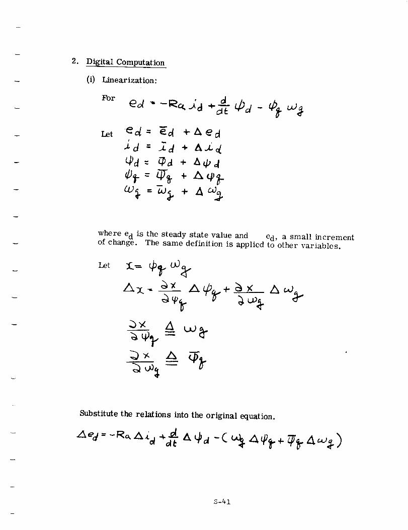
2. Digital Computation
(i) Linearization:
For
Let ed- gd +Aect
./d - _d + a.Z,{
t_d= _a + aC, d
where e d is the steady state value and ed, a small incrementof change. The same definition is applied to other variables.
Let
Substitute the relations into the original equation.
S-41
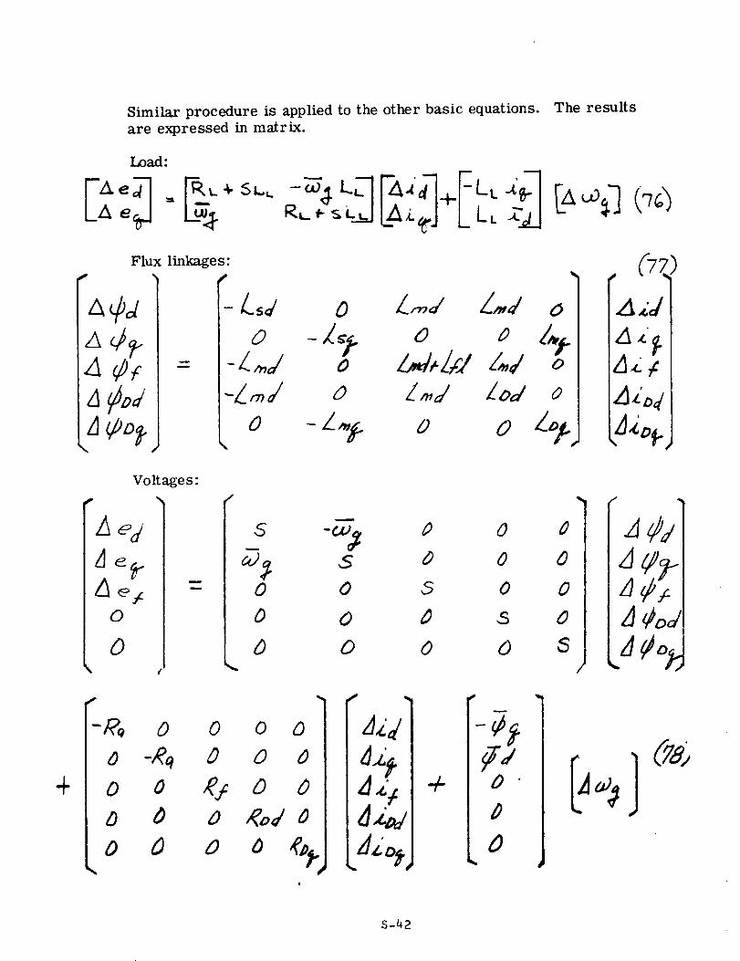
Similar procedure is applied to the other basic equations. The results
are expressed in matrix.
Load:
Flux linkage s:
A4_.A Ca,_ =a¢_z
-L_# o LrW Z,.d
-LW o l_, id Z_d o-L,_J o L,W lo# o
o -z,.# _, 0 Zol_"
4zl
Vo It age s:
k _d s -__ o o o" "deal"
L_e _ : 0 0 5 0 0o o o ,o s o 2 ¢o#
o , . a o o o s a¢og
/ c -,oo o c 1%/ I_ 1(Ta;
+Io o e,,o o I_._I ÷ L;c c c o % L_.o,j
S-42
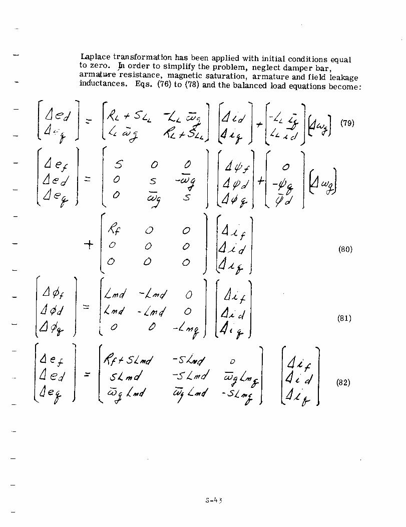
dU,_ed
¢
JCd
4e 6
Jed
Laplace transformation has been applied with initial conditions equal
to zero. In order to simplify the problem, neglect damper bar,
armatm'e resistance, magnetic saturation, armature and field leakageinductances. Eqs. (76) to (78) and the balanced load equations become:
0 0
0 0
0 o
m I
l'd ÷ -:
[dzj. ,i_.,dI
0
,;i<, i
"Zz,<1d,d
(79)
(80)
(81)
(82)
,S-43
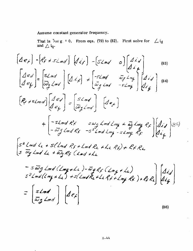
Assume constant generator frequency.
That is %.w g = 0. From eqs. (79) to (82). First solve for _..i d
_nd _h"
(83)
1
I (84)
(86)
S-44
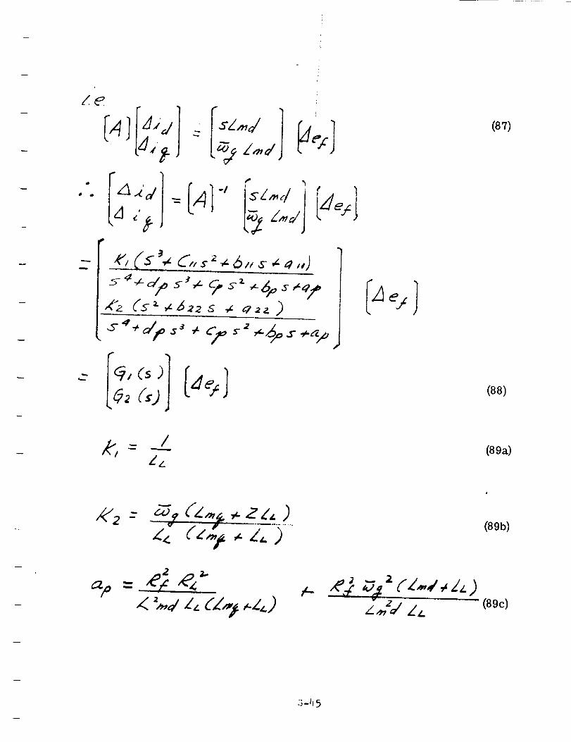
• il
I+
,e',,+(,.+_ C, +..__.<_,,.+-,, ,+,,,j
(87)
(88)
(89a)
,4"2 - -_+' (z,,,,+._.z,/, )47"
z<. (z ,,z',.)(89b)
(89c)
S-I15
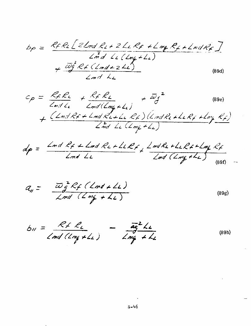
--",,>,=d_'.,(_.#.,_s <Z.,,d..-_L,_'J
Z_ d A._
_.Z,.J
(89d)
C/D
4-- ('_ _,y _,c ,_ L_,_ '/_2_-Z_ _/
_" f-_Vd (89e)
Z',,-,,,dZL
(89g)
(89h)
S-46
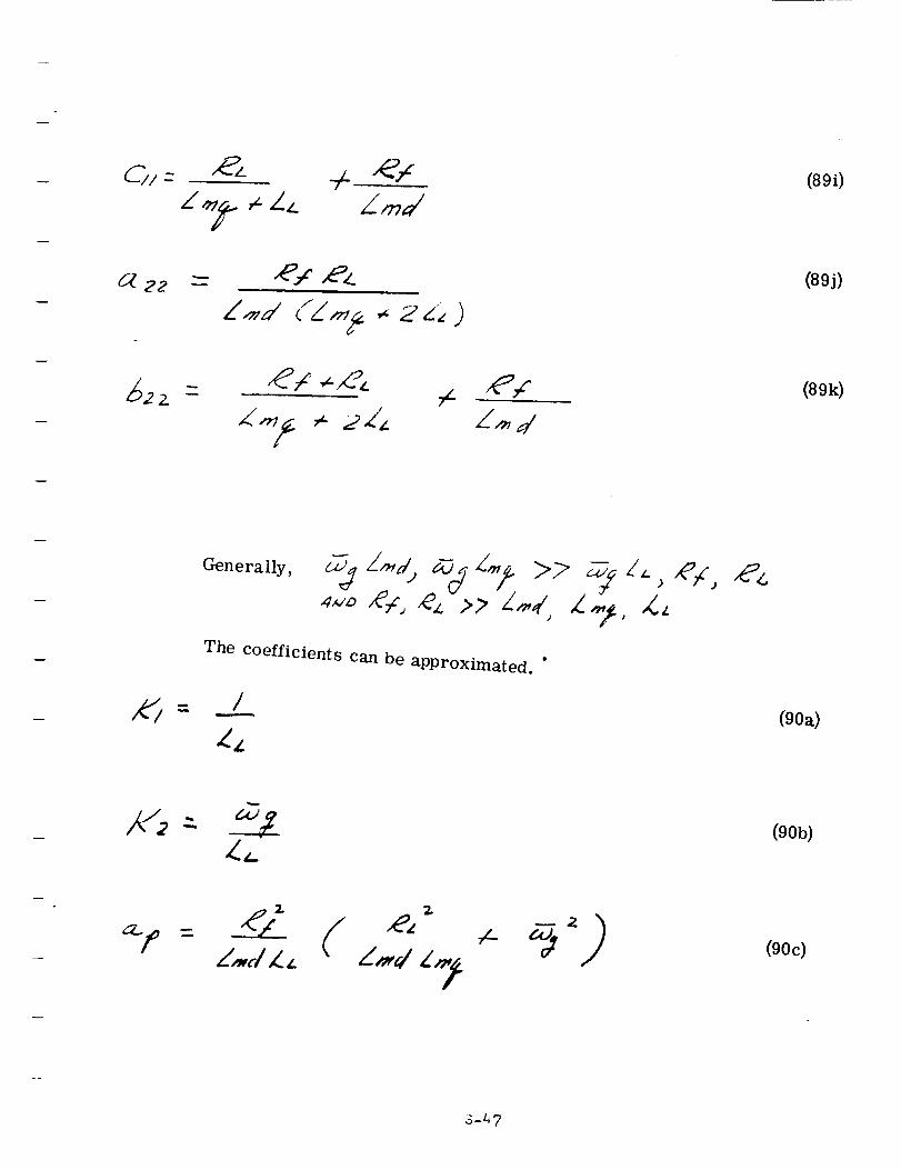
.
t-
(89i)
(89j)
(89k)
Generally,
The coefficients can be apProximated. "
i
_Z
(90a)
2.(90b)
Z,,,J Z._ Z_d L ,._(90c)
3-47
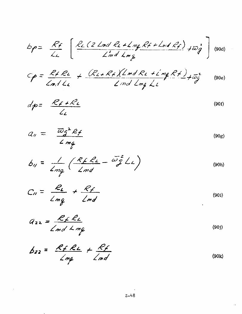
/
(90d)
(90e)
(9Of)
/ (-_z,Z'_,V
(90g)
(9Oh)
(90i)
(90j)
(9Ok)
S-_8
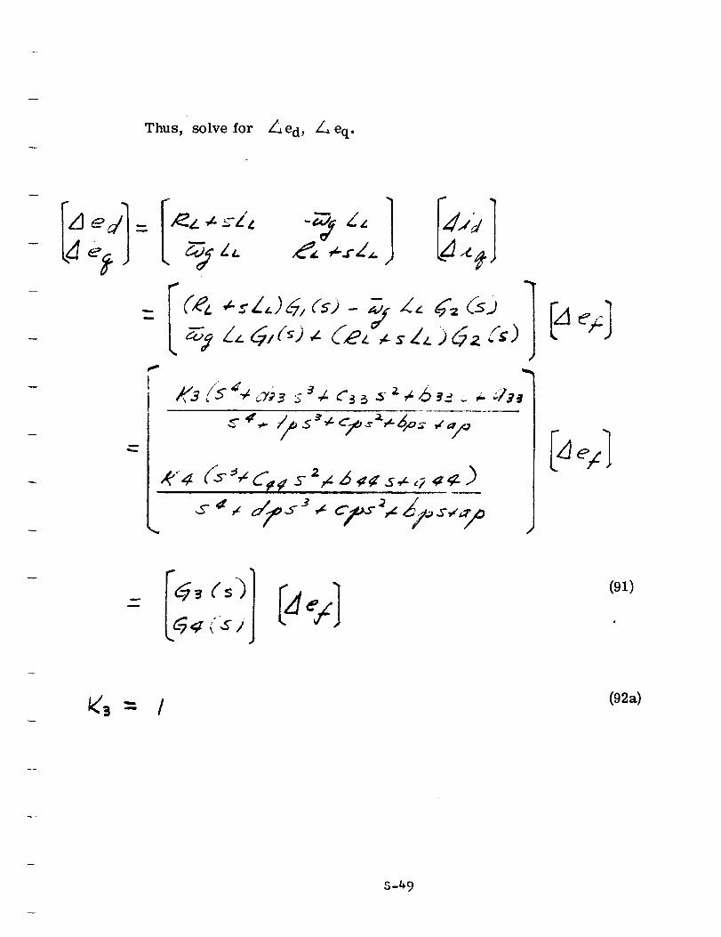
Thus, solve for Z_ed, /-,eq.
w
l
(91)
i_'3 -_ /(92a)
S-_9
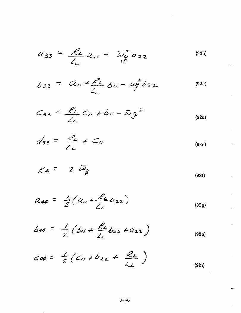
Q22(92b)
m _,, _ _ 6,,- __ __ (92c)
Z.
- ,/_z._/_ - _Z _"_i
LL_
z.
(92d)
(92e)
k'¢- z(92f)
.2 _/L (92g)
(92h)
(92i)
S-50
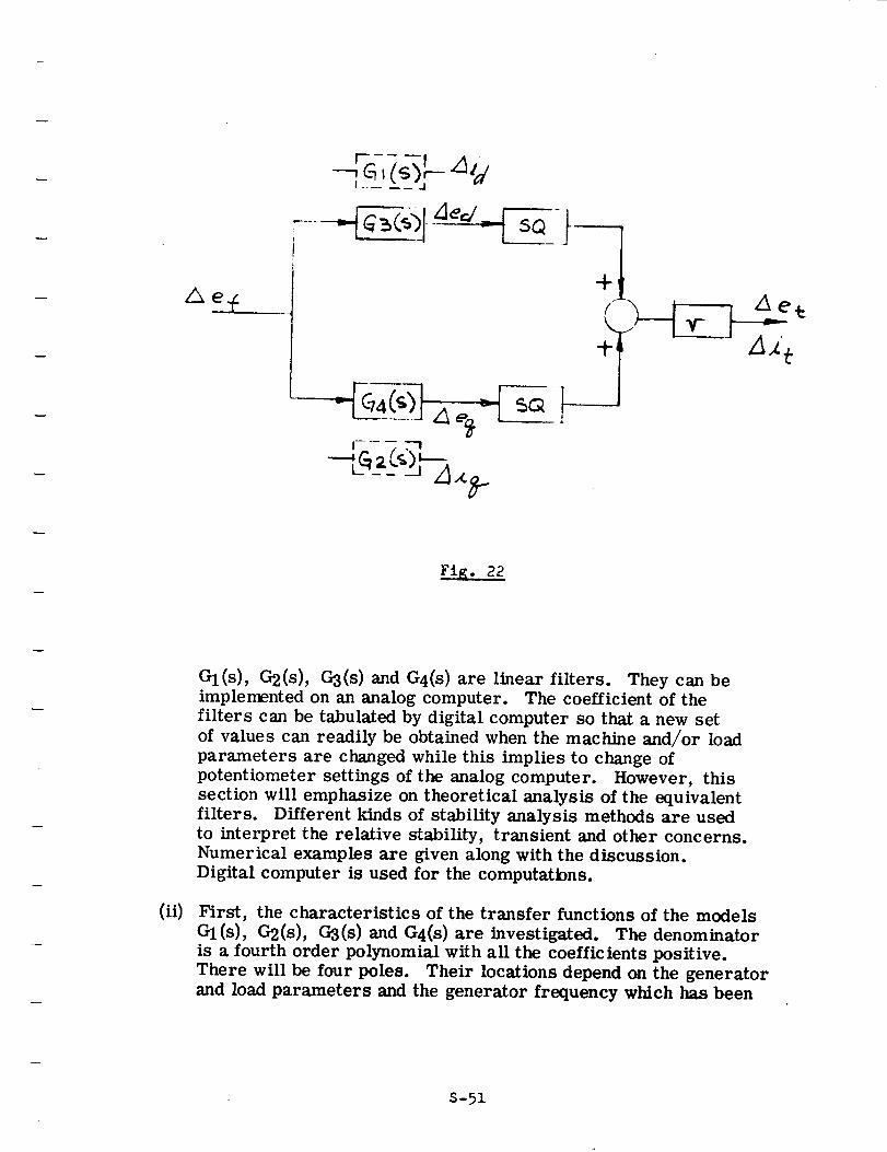
| + --
Fig. 22
(ii)
GI(S), G2(s), G3(s) and G4(s ) are linear filters. They can be
implemented on an analog computer. The coefficient of the
filters can be tabulated by digital computer so that a new set
of values can readily be obtained when the machine and/or load
parameters are changed while this implies to change of
potentiometer settings of the analog computer. However, this
section will emphasize on theoretical analysis of the equivalent
filters. Different kinds of stability analysis methods are used
to interpret the relative stability, transient and other concerns.
Numerical examples are given along with the discussion.
Digital computer is used for the computatbns.
First, the characteristics of the transfer functions of the models
Gl(s), G2(s), G3(s) and G4(s) are investigated. The denominator
is a fourth order polynomial with all the coefficients positive.
There will be four poles. Their locations depend on the generator
and load parameters and the generator frequency which has been
S-51
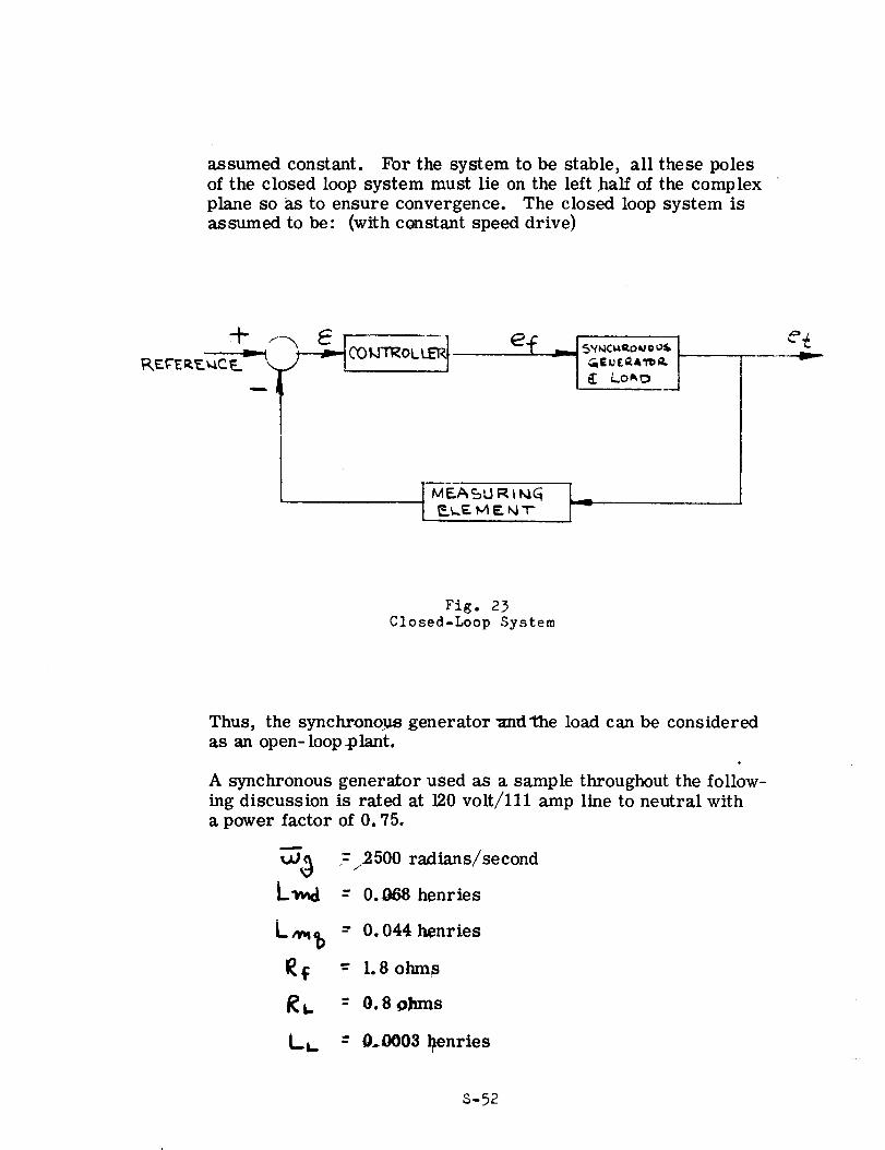
assumed constant. For the system to be stable, all these poles
of the closed loop system must lie on the left half of the complex
plane so as to ensure convergence. The closed loop system isassumed to be: (with ccmstant speed drive)
elc _ is"_c_2°"°°sG EUEG&1'bQ,.
E Lo_
| MF..,_SLIRt_G [ _I
e_v
Fig. 23
C1osed-Leop System
Thus, the synchronous generator and'the load can be considered
as an open- loop .plant.
A synchronous generator used as a sample throughout the follow-ing discussion is rated at 120 volt/lll amp line to neutral with
a power factor of 0.75.
_ =2500 r_l_ns/second
-- 0.o68henries
L_ = 0.044 henries
I_f -- 1.8 ohms
t_. = 0.8 ohms
t-L. - 0,,0003 _enries
S-52
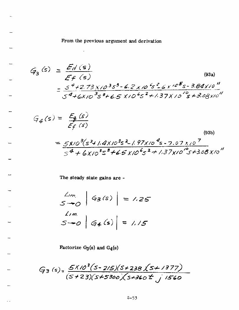
From the previous argument and derivation
Ed (_)
E: (_ )- ,5 e¢2. 73._"/D 3s_
(93a)
- _. Z x zo @ ": 6 x ,[&s- _ 8dx'/_ "/0
s _3.o6_/oi/
_4(s) =E': :s)
= 5X/o 3fs34 /,,_x/o3s 2- /. PZx/o _ -?7
.07 _/0
(93b)
z 4-/,37X/o "°iI
The steady state gains are -
S--_O
.5----o _ _ ('5)
= /,2_-
= /,/5"
Factorize 03(s ) and G4(s)
G_ (_)- _x/o Ts- 2/s)(s +23a.(s_- / _77)
S-53
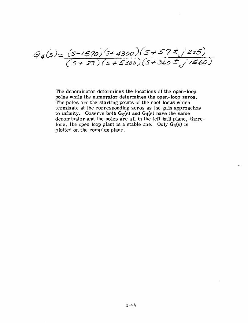
The denominator determines the locations of the open-loop
poles while the numerator determines the open-loop zeros.
The poles are the starting points of the root locus which
terminate at the corresponding zeros as the gain approaches
to infinity. Observe both G3(s ) and G4(s ) have the same
denominator and the poles are all in the left half plane, there-
fore, the open loop plant is a stable one. Only G4(s) is
plotted on the complex plane.
s-54
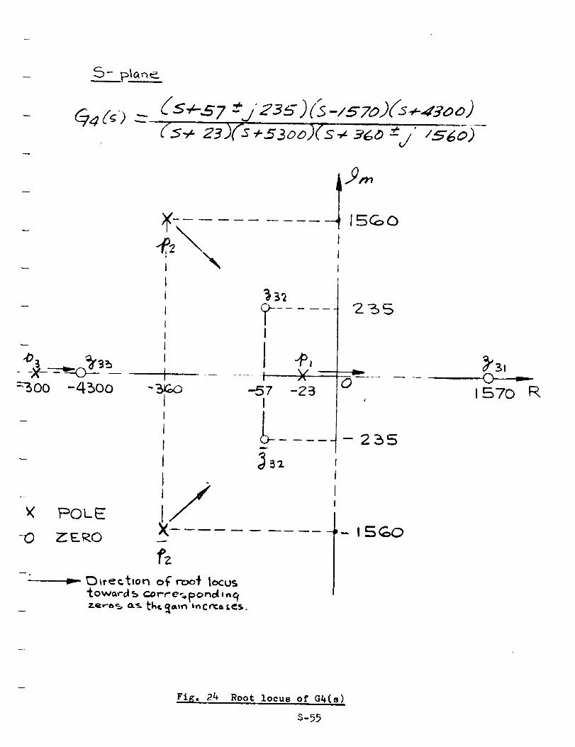
---_oo -4500
_( F_OLE
RD _E_O
r
_- ......... 15GO
I
I
, yIj I
' II I 4 _,
- :sr.,o --,37 -23I
0
-255
Ji( .....
_,_ctton of roo_ locus"f.ow_,'-a_ corre_ponel,n£
1S¢=_:)
FiK. 24 Root locus ot G_(s)
S-55
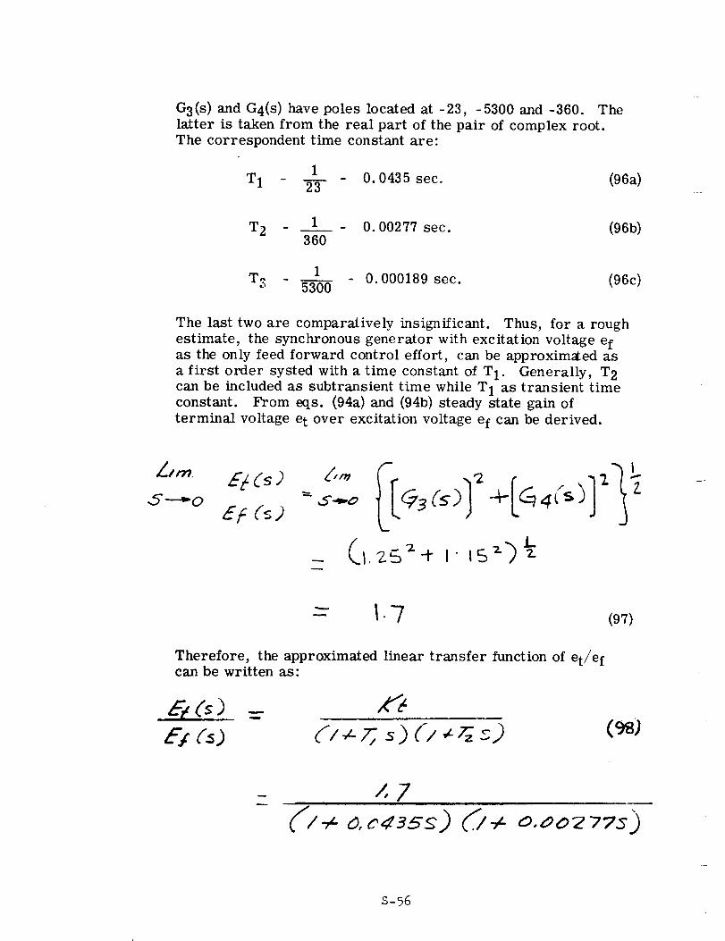
G3(s) and G4(s ) have poles located at -23, -5300 and °360. The
latter is taken from the real part of the pair of complex root.
The correspondent time constant are:
1
T1 23 0. 0435 sec. (96a)
T2 _ 1 - 0.00277 sec. (96b)360
1T_. 0. 000189 sec. (96c)_' 5300
The last two are comparatively insignificant. Thus, for a rough
estimate, the synchronous generator with excitation voltage efas the only feed forward control effort, can be approxim_ed as
a first order systed with a time constant of T 1. Generally, T 2
can be included as subtransient time while T l as transient timeconstant. From eqs. (94a) and (94b) steady state gain of
terminal voltage e t over excitation voltage ef can be derived.
,5"----_O
EF (5) 3(s) ÷ 4(s)
-- I.-7 (97)
Therefore, the approximated linear transfer function of et/e fcan be written as:
E; (_) (98)
D-/ 0,#02 77S_)
S-56
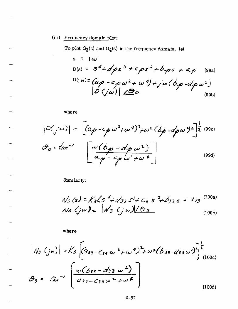
(iii) Frequency domain plot:
To plot G3(s ) and G4(s) in the frequency domain, let
s -" j
(99a)
where
(99d)
Similarly:
(lOOa)
(lOOb)
where
_ (lO0c)
S-57
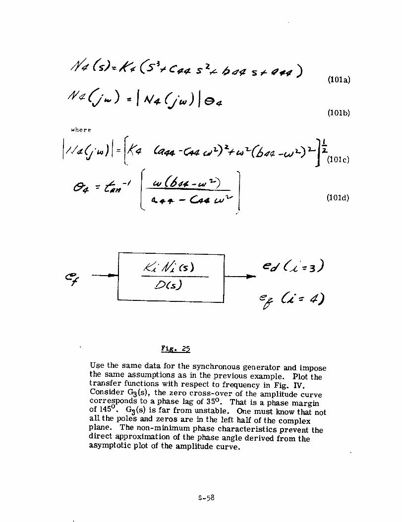
(101a)
(101b)
where
(I01d)
'0
Fig.
Use the same data for the synchronous generator and impose
the same assumptions as in the previous example. Plot the
transfer functions with respect to frequency in Fig. IV.
Consider G3(s), the zero cross-over of the amplitude curve
corresponds to a phase lag of 35 °. That is a phase marginof 145 °. G3(s) is far from unstable. One must know that not
all the poles and zeros are in the left half of the complex
plane. The non-minimum phase characteristics prevent the
direct approximation of the phase angle derived from the
asymptotic plot of the amplitude curve.
S-58
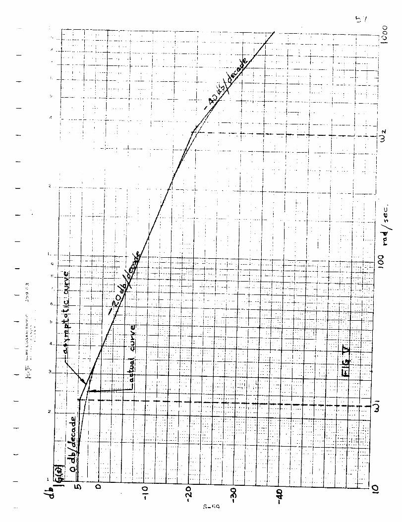
ji-- _- _, j*
-I .
:EJ
i
i
i i
5
l
I
I I
{::1
(iv) Transfer function derivation from laboratory data:
Conversely, if a transient response curve is in hand, a
transfer function can be derived from asymptotic plot in
a frequency domain curve. The break-away points of two
asymptotes with 20 db/decade decay difference determinesthe time constants. The order of the transfer function
depends on the need of accuracy in describing the
characteristics. It must be noted that a time domain plot
which is the usual case of laboratory data, should be trans-
formed into frequency domain plot before applying the
approximation technique. The abscissa should be the ratio
of output versus input in decibel while the ordinate, frequency
on radians per second. Suppose an actual curve is plotted
in Fig. D. Three asymptotic lines are approximated. The
zero db/decade line is at 4.6 db which determines the gain
of the transfer function while the two break-away points
at
S-60
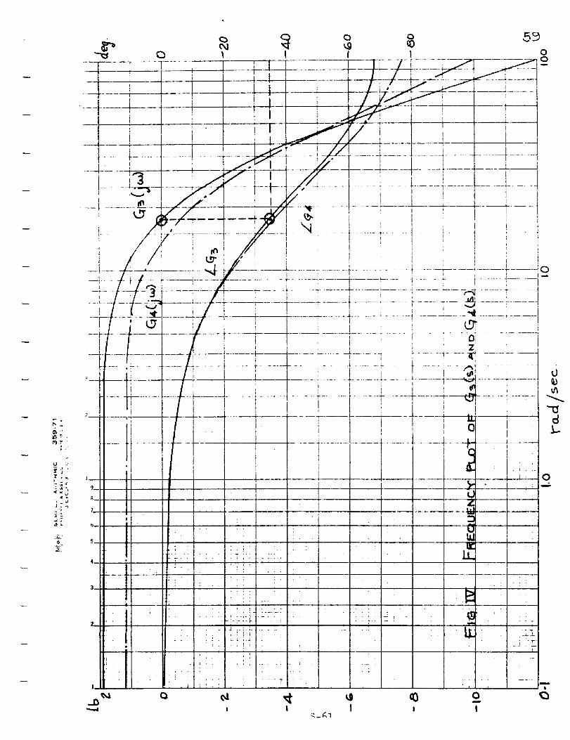
_'IZ"
U J
J
J
Ii
• I
• !
I
:i
• !1
. I
• i
, !
i
, I
I
I
i• I" I
•_: I_ I
• ::I L :1
• I I i, - I
-:-:---!_I i i
!
I
I
I
._m
I
0,iI
I
0
_h
k-
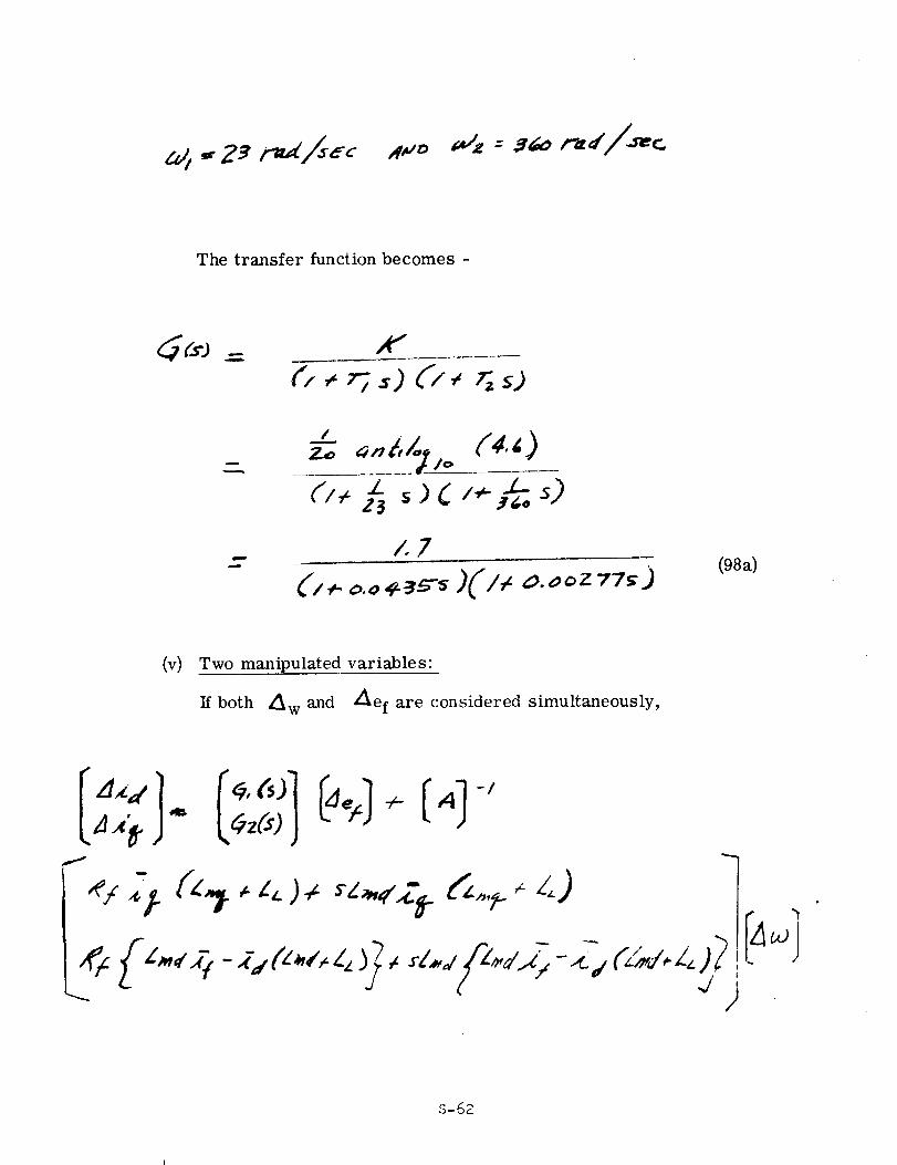
The transfer function becomes -
x7
- (/<_ ,>.,,÷_5-,,)(I,, _.ooz 77_) (98_)
(v) Two manipulated variable s"
If both L_ w and Z_lef are considered simultaneously,
-/
S-62
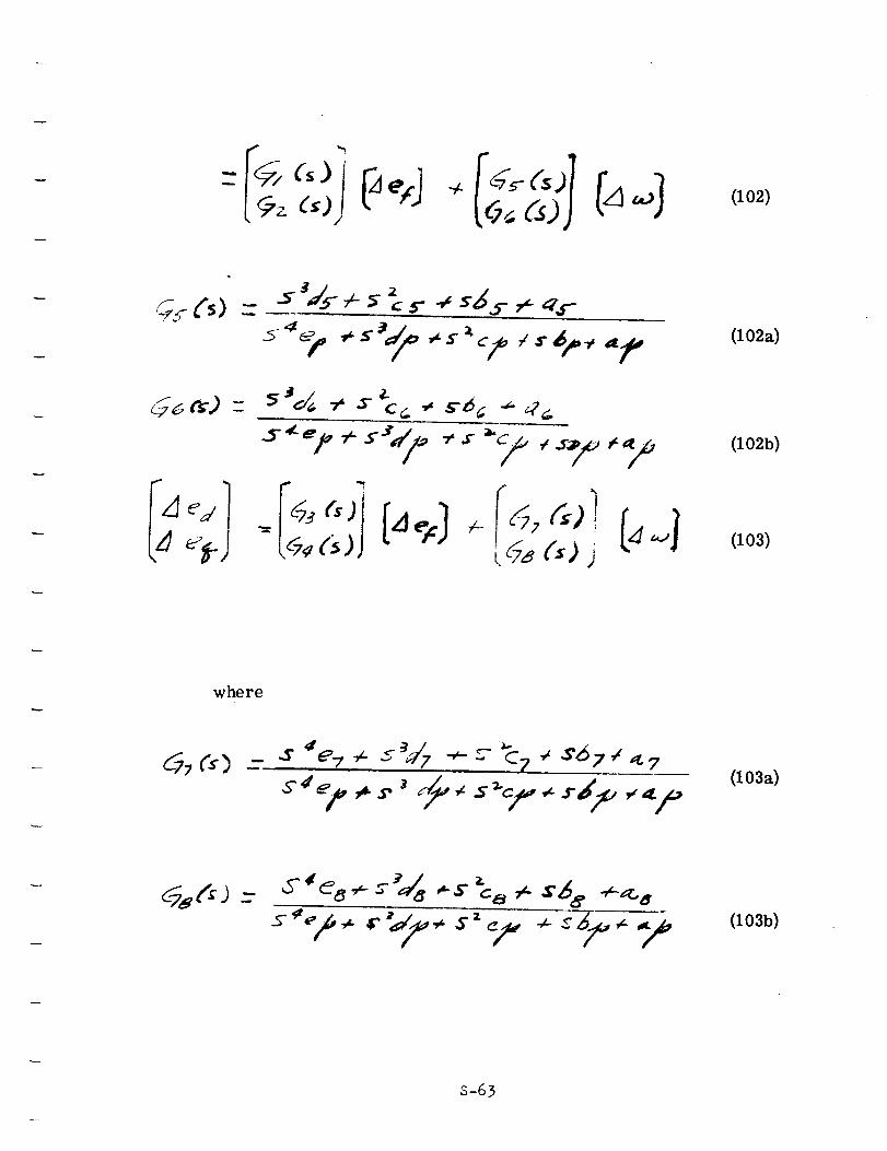
(102)
Cs)-
f
__26 ¢s) - 5Jd./_-_2 -z
(102a)
(102b)
(103)
where
(103a)
_8 [s, ) _-(103b)
S-63
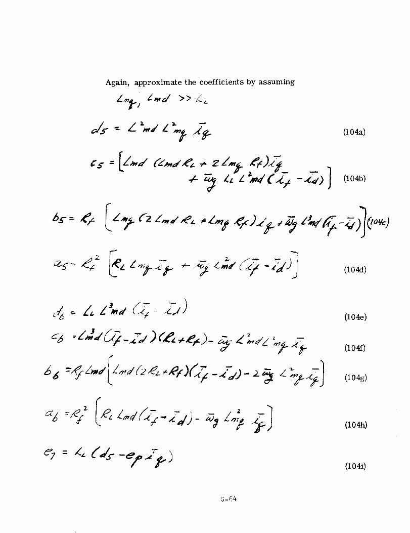
Again, approximate the coefficients by assuming
" 4Js : L _." L "_I" (t 04a)
(ZO4D)
(104e)
(104f)
(104g)
(104h)
(104i)
S-64
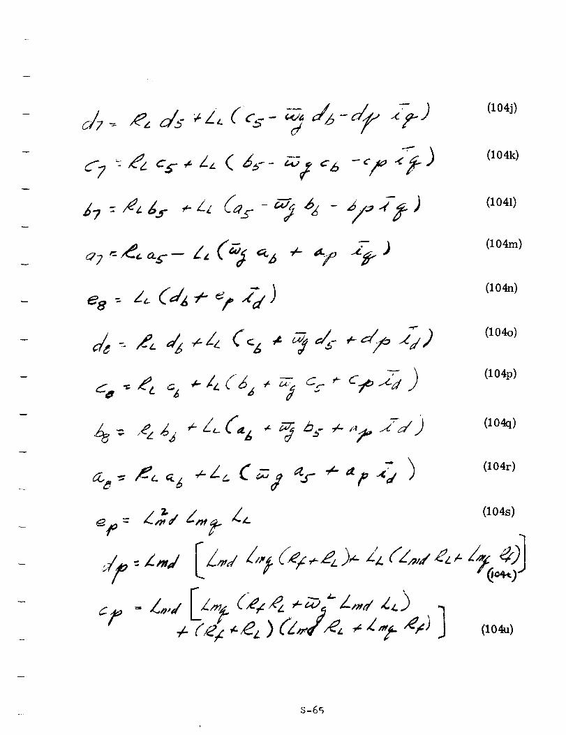
I
(104j)
(104k)
(1041)
4- *_-_o _ J (104m)
(104n)
(104o)
(104p)
(104q)
(104r)
S-65
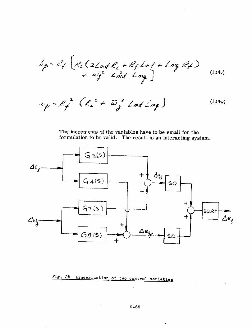
(iO4v)
(104w)
The increments of the variables have to be small for the
formulation to be valid. The result is an interacting system.
+I
Fig. 26 Linearization of two control variable
S-66
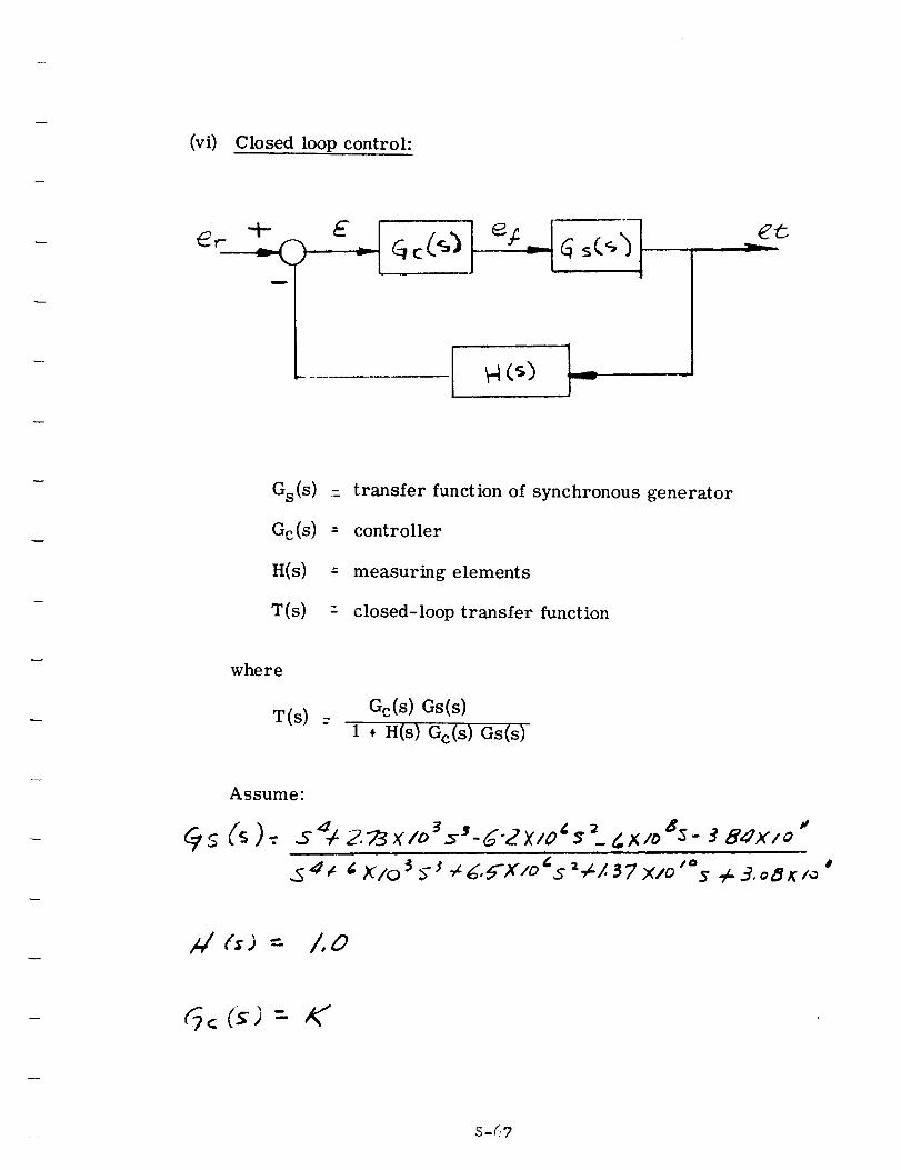
(vi) Closed loop control:
E
Gs(s)
Gc(s)
H(s)
T(s)
: transfer function of synchronous generator
-" controller
-" measuring elements
= closed-loop transfer function
where
T(s)Go(s) Gs(s)
1 + H(s) Gc(S ) Gs(s)
Assume"
Qs (s ).: 5d_ 2.:_3_(/o 3=_'-d'2X/O_'_i_X/l, 85- :?8dX/ o "
A/ (;) = 1,0
_< ("_)= K"
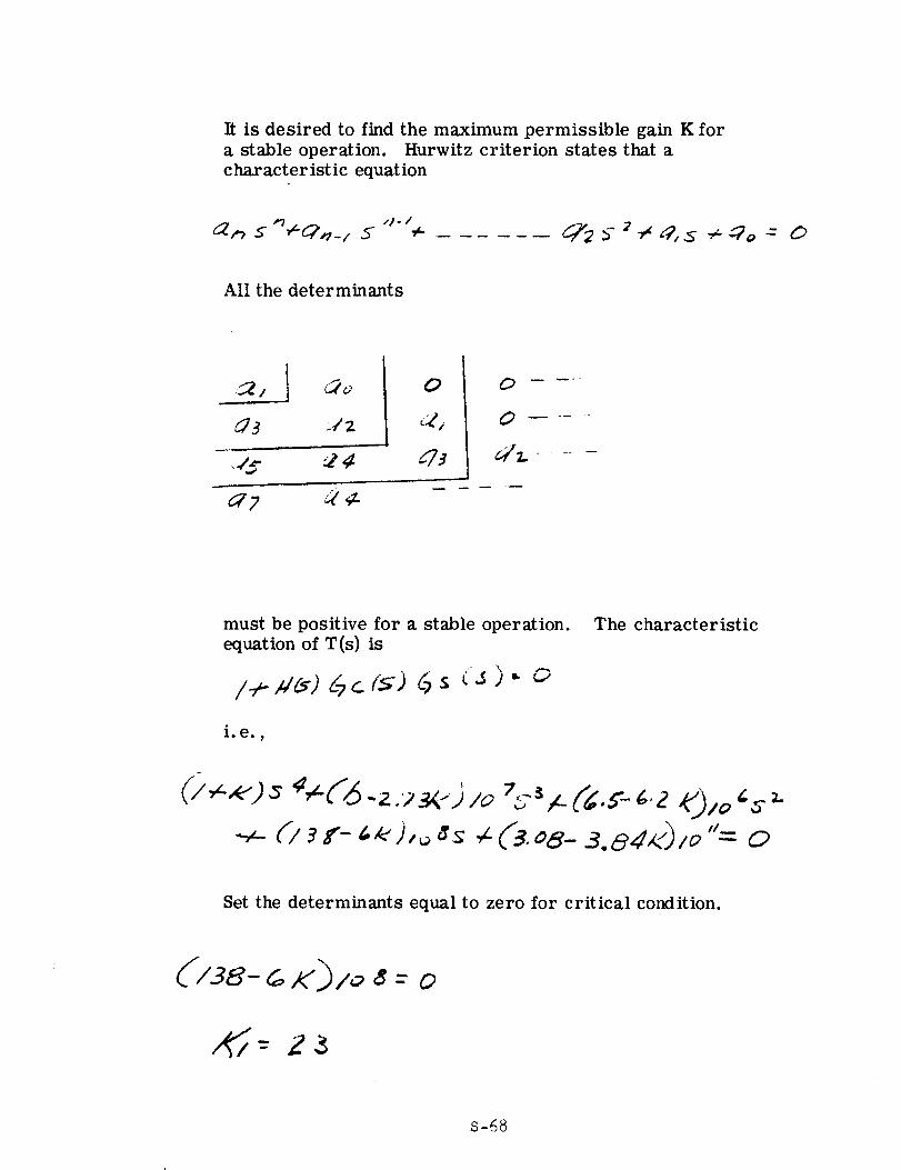
It is desired to find the maximum permissible gain K for
a stable operation. Hurwitz criterion states that acharacteristic equation
,]- I
All the determinants
0
_73
0
6,/z. .....
must be positive for a stable operation.equation of T(s) is
i. e. 9
The characteristic
Set the determinants equal to zero for critical condition.
('/38-_ i<')Io 8 : 0
S-68
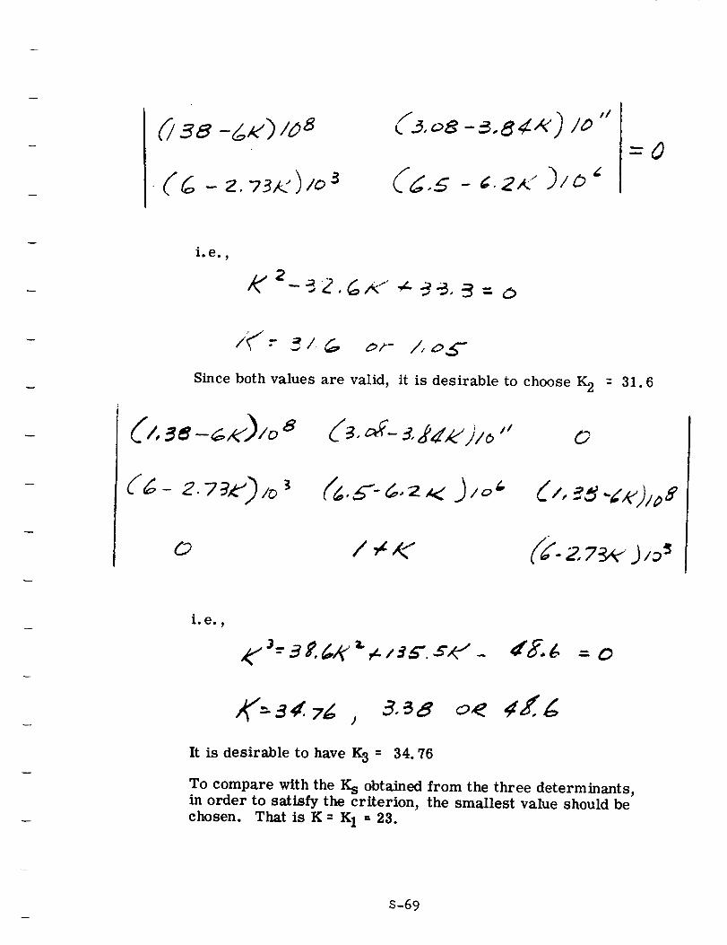
(4 - z. 73,.-)/o3 _ /_ ..5 - _. 2,< )/O _
i. e. ,
2- 5 Z. (_,_" ¢-" :-3_, :3 - o
Since both values are valid,
0
/,o5-
it is desirable to choose K 2
d3. d- _,2_.'j/o " o
/ ,h /<
= 31.6
(/, _,q ..b,'j,, ,_s
(/K- 2, 7_ J /3 s
i. e. ,
,¢,"J--"3 £ 4K "a"e.. / :_a'. ,s',¢" - dg._ = o
,_"-a4. _ j o< ¢Z g
It is desirable to have K 3 = 34.76
To compare with the K s obtained from the three determinants,in order to satisfy the criterion, the smallest value should be
chosen. That isK= K 1- 23.
S-69
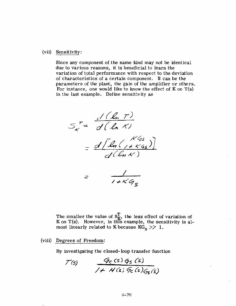
(vii) Sensitivity:
Since any component of the same kind may not be identical
due to various reasons, it is beneficial to learn the
variation of total performance with respect to the deviation
of characteristics of a certain component. It can be the
parameters of the plant, the gain of the amplifier or others.For instance, one would like to know the effect of K on T(s)
in the last example. Define sensitivity as
5S: d(-_ +J
'+++I+]/-.z ++..+,>
/
/ + "(_s
(viii)
The smaller the value of ST , the less effect of variation of
K on T(s). However, in thYs example, the sensitivity is al-
most linearly related to K because KG s :>_ 1.
Degrees of Freedom:
By investigating the closed-loop transfer function
/"- "¢_'_ _ _)5,f_)
S-70
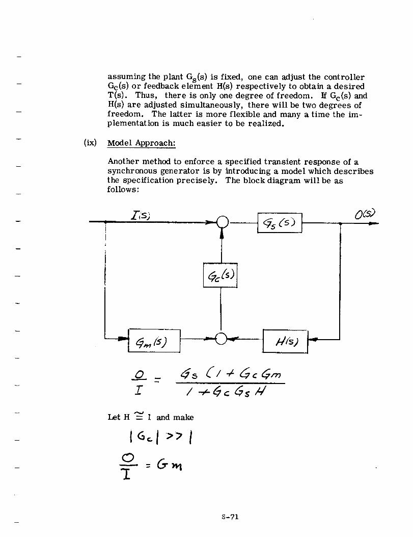
assuming the plant Gs(s ) is fixed, one can adjust the controllerGc(s) or feedback element H(s) respectively to obtain a desired
T(s). Thus, there is only one degree of freedom. If Gc(s ) and
H(s) are adjusted simultaneously, there will be two degrees of
freedom. The latter is more flexible and many a time the im-
plementation is much easier to be realized.
Model Approach:
Another method to enforce a specified transient response of a
synchronous generator is by introducing a model which describes
the specification precisely. The block diagram will be asfollows:
I
0(s)
Let H _ 1 and make
iGol IcD
:[
S-71
where
O(s) :
I(s) :
Gm(s ) -
output
input
transfer function of model
S-72
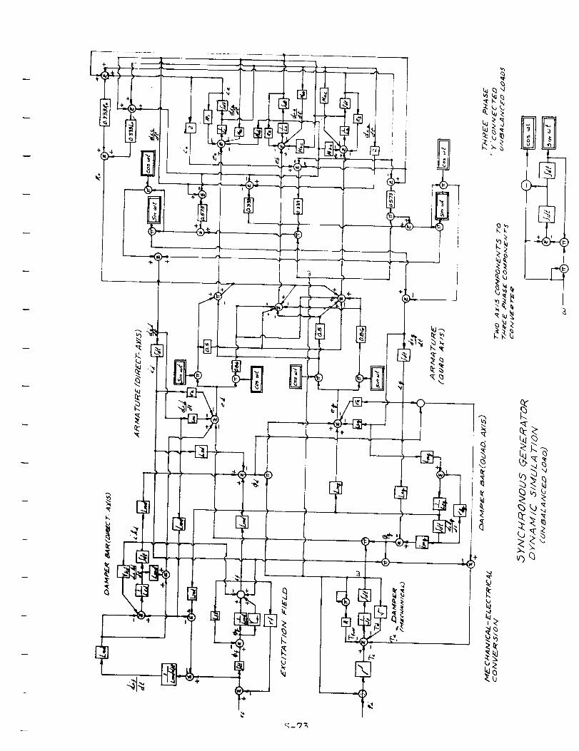
q
!
!
_bq
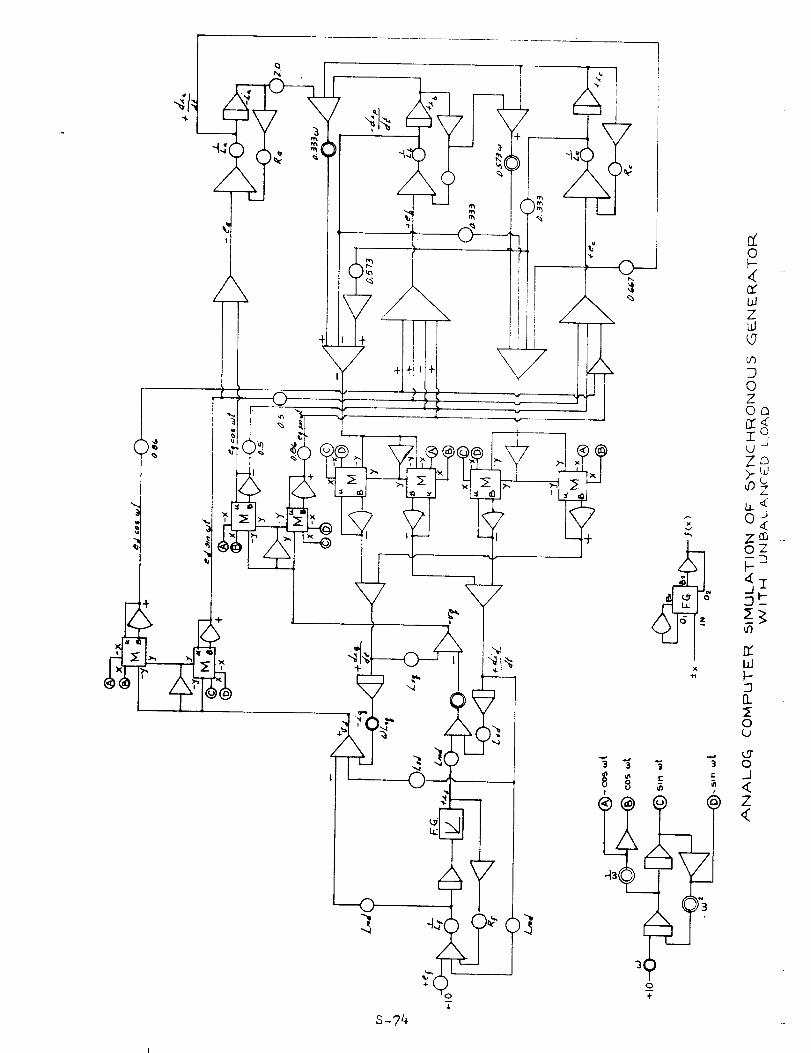
0
40g
Z
CO
D0ZOn12::42 °_J
ZD;,_uJ
Jo<ZcaoZ
F _
W
&
o
S-74
÷ )
4
0
Z
SECTION T
!
!
!
!
!
! SYMBOL TAB LE S
!
!
!
!
!
!
!
!
!
!
SE C TION T
|
It
w
w
m
J
i
w
J_L
I
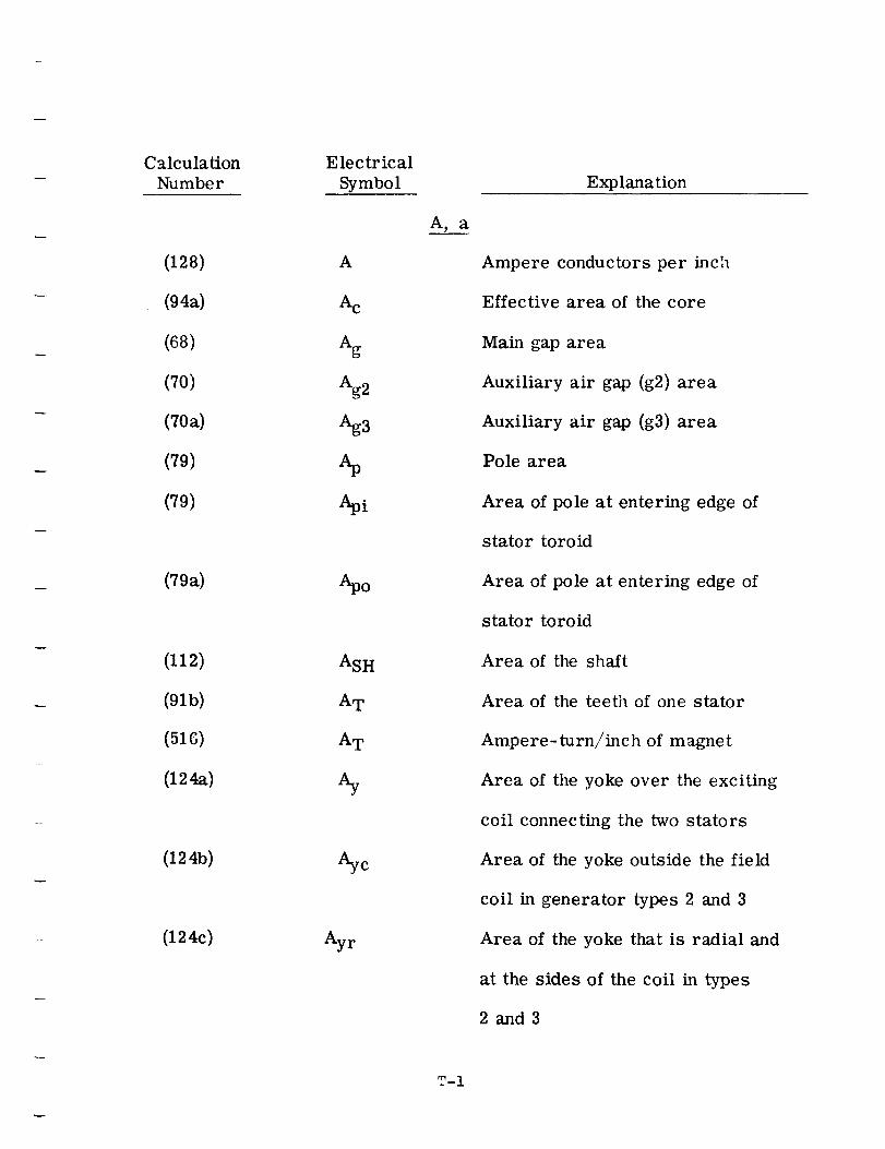
C_tlculation
Number
(128)
(94a)
(68)
(70)
(702)
(79)
(79)
(79a)
(112)
(91b)
(516)
(124a)
(124b)
(124c)
Electrical
Symbol
A
Ac
Ag
Ag2
Q3
Apo
ASH
AT
AT
%
Aye
Ayr
A, a
T-I
Explanation
Ampere conductors per inch
Effective area of the core
Main gap area
Auxiliary air gap (g2) area
Auxiliary air gap (g3) area
Pole area
Area of pole at entering edge of
stator toroid
Area of pole at entering edge of
stator toroid
Area of the shaft
Area of the teeth of one stator
Ampere-turn/inch of magnet
Area of the yoke over the exciting
coil connecting the two stators
Area of the yoke outside the field
coil in generator types 2 and 3
Area of the yoke that is radial and
at the sides of the coil in types
2 and3
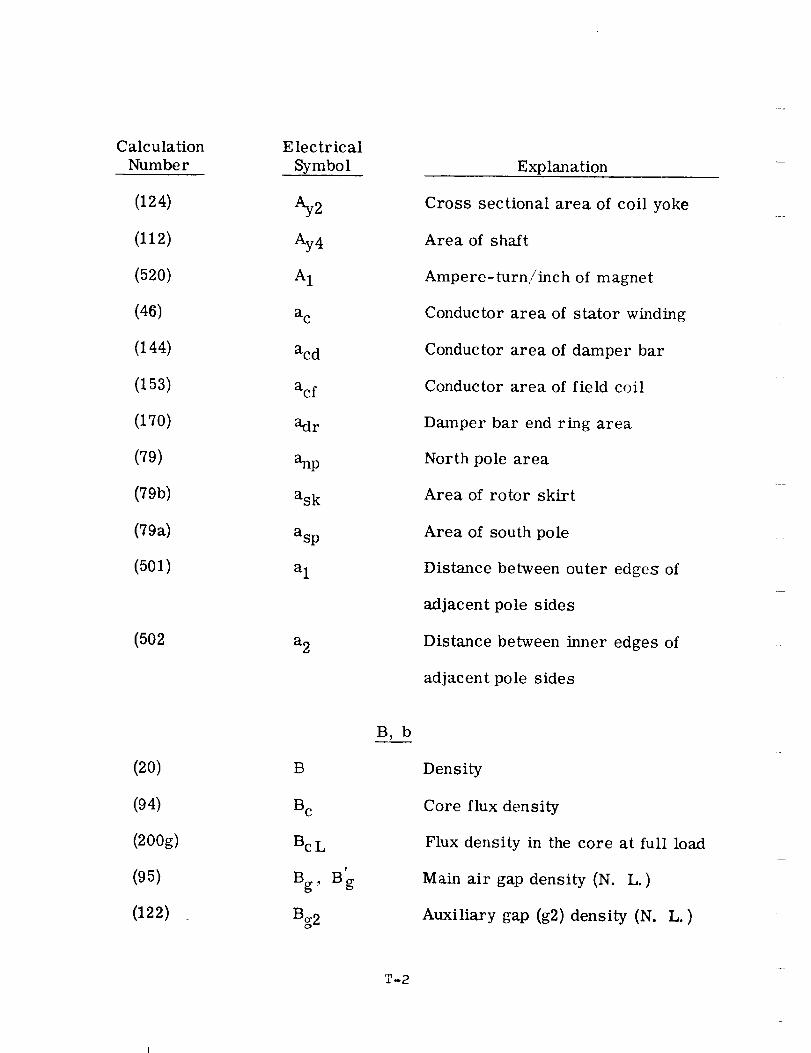
CalculationNumber
(124)
(112)
(520)
(46)
(144)
(153)
(170)
(79)
(79b)
(79a)
(501)
(502
(20)
(94)
(200g)
(95)
(122)
Electrical
Symbol
Ay2
Ay4
A1
a c
acd
acf
adr
anp
ask
asp
a 1
a 2
B
B c
Bc L
Bg, Bg
Bg2
B, b
T-2
Explanation
Cross sectional area of coil yoke
Area of shaft
Ampere-turn/inch of magnet
Conductor area of stator winding
Conductor area of damper bar
Conductor area of field coil
Damper bar end ring area
North pole area
Area of rotor skirt
Area of south pole
Distance between outer edges of
adjacent pole sides
Distance between inner edges of
adjacent pole sides
Density
Core flux density
Flux density in the core at full load
Main air gap density (N. L. )
Auxiliary gap (g2) density (N. L. )
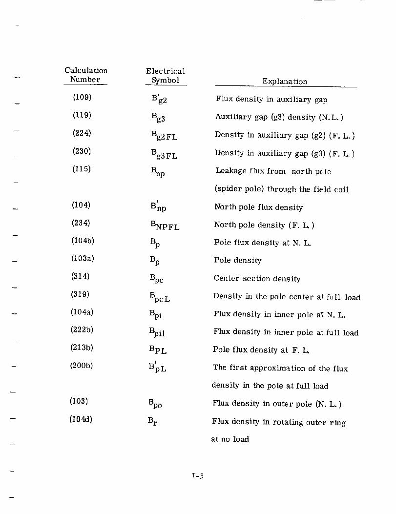
CalculationNumber
(109)
(119)
(224)
(230)
(115)
(104)
(234)
(104b)
(103a)
(314)
(319)
(104a)
(222b)
(2135)
(2005)
(103)
(104d)
Electrical
Symbol
B' 2
Bg3
Bg2 FL
Bg3 FL
Bnp
!
Bnp
BNPFL
Bp
%
BpcB
pcL
Bpi
Bpil
BpL
BpL
Spo
Br
Explanation
Flux density in auxiliary gap
Auxiliary gap (g3) density (N.L.)
Density in auxiliary gap (g2) (F. L. )
Density in auxiliary gap (g3) (F. L. )
Leakage flux from north p¢_le
(spider pole) through the field coil
North pole flux density
North pole density (F. L. )
Pole flux density at N. L.
Pole density
Center section density
Density in the pole center al full load
Flux density in inner pole aI N. L.
Flux density in inner pole at full load
Pole flux density at F. L.
The first approximation of the flux
density in the pole at full load
Flux density in outer pole (N. L. )
Flux density in rotating outer ring
at no load
T-3
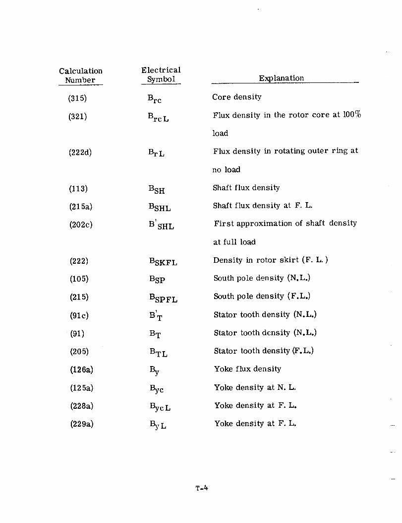
CalculationNumber
(315)
(321)
(222d)
(113)
(215a)
(202c)
(222)
(105)
(215)
(91c)
(91)
(205)
(126a)
(125a)
(228a)
(229a)
Electrical
Symbol
Brc
Brc L
BrL
BSH
BSHL
B'SH L
BSKFL
BSp
BSPFL
B'T
BT
BTL
By
%c
BycL
Explanation
Core density
Flux density in the rotor core at 100%
load
Flux density in rotating outer ring at
no load
Shaft flux density
Shaft flux density at F. L.
First approximation of shaft density
at full load
Density in rotor skirt (F. L. )
South pole density (N.L.)
South pole density (F.L.)
Stator tooth density (N.L.)
Stator tooth density (N.L.)
Stator tooth density (F.L.)
Yoke flux density
Yoke density at N. L.
Yoke density at F. L.
Yoke density at F. L.
T-4
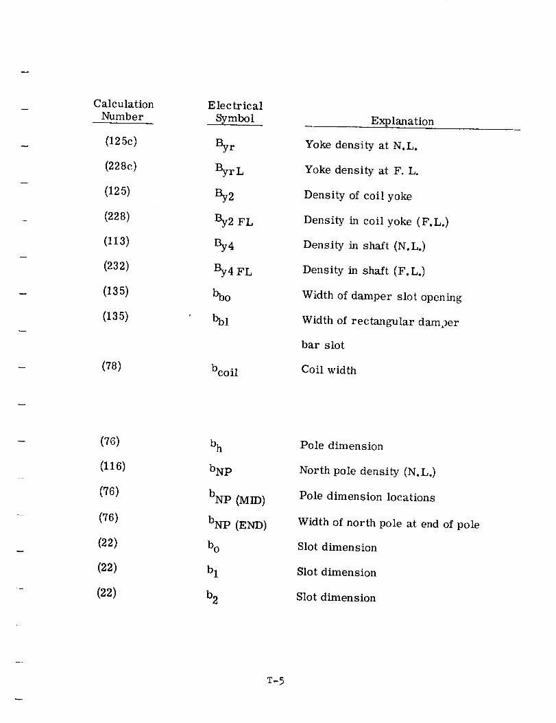
Calculation
Number
(125c)
(228c)
(125)
(228)
(113)
(232)
(135)
(135)
(78)
Electrical
Symbol
r
ByrL
By2 FL
%4
By4 FL
bcoil
Explanation
Yoke density at N.L.
Yoke density at F. L.
Density of coil yoke
Density in coil yoke (F.L.)
Density in shaft (N.L.)
Density in shaft (F.L,)
Width of damper slot opening
Width of rectangular damper
bar slot
Coil width
(76)
(116)
(76)
(76)
(22)
(22)
(22)
b h
bNp
bNp (MID)
bNp (END)
b o
b 1
b 2
Pole dimension
North pole density (N.L.)
Pole dimension locations
Width of north pole at end of pole
Slot dimension
Slot dimension
Slot dimension
T-5
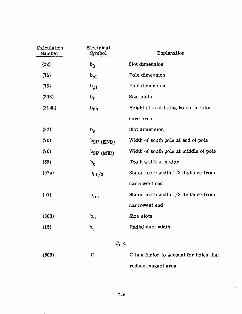
CalculationNumber
(22)
(76)
(76)
(303)
(3145)
(22)
(76)
(76)
(58)
(57a)
(57)
(303)
(15)
(508)
Electrical
Symbol
b 3
br
brh
b s
bSp (END)
bsp (MID)
b t
btl/3
btm
btr
Explanation
Slot dimension
Pole dimension
Pole dimension
Size slots
Height of ventilating holes in rotor
core area
Slot dimension
Width of south pole at end of pole
Width of south pole at middle of pole
Tooth width at stator
Stator tooth width 1/3 distance from
narrowest end
Stator tooth width 1/2 distance from
narrowest end
Size slots
Radial duct width
C is a factor to account for holes that
reduce magnet area
T-6
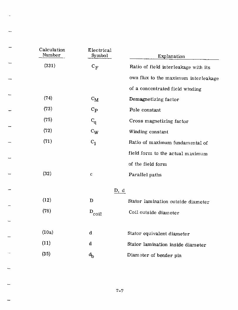
CalculationNumber
(331)
(74)
(73)
(75)
(72)
(71)
(32)
(12)
(78)
(10a)
(11)
(35)
E lec tr ic al
Symbol
C F
CM
Cp
cq
CW
C I
C
D
Dcoil
d
d
D, d
Explanation
Ratio of field interleakage with its
own flux to the maximum interleakage
of a concentrated field winding
Demagnetizing factor
Pole constant
Cross magnetizing factor
Winding constant
Ratio of maximum fundamental of
field form to the actual m_:aximum
of the field form
Parallel paths
Stator lamination outside diameter
Coil outside diameter
Stator equivalent diameter
Stator lamination inside diameter
Diam__ter of bender pin
T-?
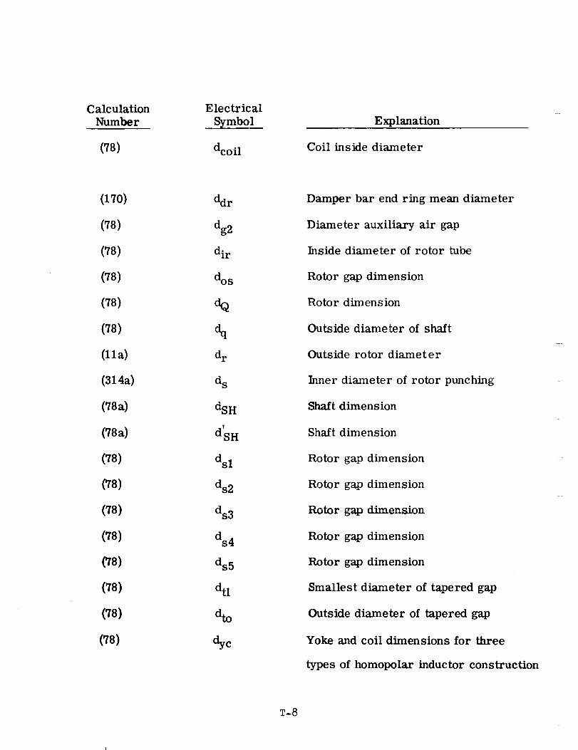
Calculation
Number
(78)
Electrical
Symbol
dcoil
Explanation
Coil inside diameter
(170)
(7s)
(78)
(78)
(78)
(78)
(lla)
(314a)
(78a)
(78a)
(78)
(78)
(78)
(78)
(78)
(78)
(78)
(78)
ddr
dg2
dir
dos
dq
%dr
d s
dSH
V
dSH
dsl
ds2
ds3
ds4
ds5
dtl
%
dye
Damper bar end ring mean diameter
Diameter auxiliary air gap
Inside diameter of rotor tube
Rotor gap dimension
Rotor dimension
Outside diameter of shaft
Outside rotor diameter
Inner diameter of rotor punching ....
Shaft dimension
Shaft dimension
Rotor gap dimension
Rotor gap dimension
Rotor gap dimension
Rotor gap dimension
Rotor gap dimension
Smallest diameter of tapered gap
Outside diameter of tapered gap
Yoke and coil dimensions for three
types of homopolar inductor construction
T-8
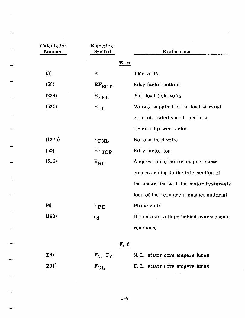
CalculationNumber
(3)
(56)
(238)
(525)
(127b)
(55)
(516)
(4)
(198)
(98)
(2oi)
Electrical
Symbol
E
E FBOT
EFFL
EFL
EFNL
E F TOP
ENL
EpH
ed
Fc, Fc
FCL
Explanation
Line volts
Eddy factor bottom
Full load field volts
Voltage supplied to the load at rated
current, rated speed, and at a
sFecified power factor
No load field volts
Eddy factor top
Ampere-turn/inch of magnet vaJme
corresponding to the intersection of
the shear line with the major hysteresis
loop of the permanent magnet material
Phase volts
Direct axis voltage behind synchronous
reactance
stator core ampere turns
stator core ampere turns
T-9
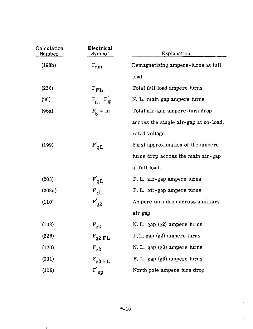
Calculation
Number
(198b)
(236)
(96)
(96a)
(199)
(203)
(208a)
(110)
(123)
(225)
(120)
(231)
(106)
Electrical
Symbol
Fdm
FFL
Fg F', g
Fg+ m
FgL
FgL
'g2
Fg2
Fg2 FL
Fg3
Fg3 FL
F'np
Explanation
Demagnetizing ampere-turns at full
load
Total full load ampere turns
N.L. main gap ampere turns
Total air-gap ampere- turn drop
across the single air-gap at no-load,
rated voltage
First approximation of the ampere
turns drop across the m_tin air-gap
at full load.
F.L. air-gap ampere turns
F.L. air-gap ampere turns
Ampere turn drop across auxiliary
air gap
N.L. gap (g2) ampere turns
F.L. gap (g2) ampere turns
N.L. gap (g3) ampere turns
F.L. gap (g3) ampere turns
North pole ampere turn drop
T-IO
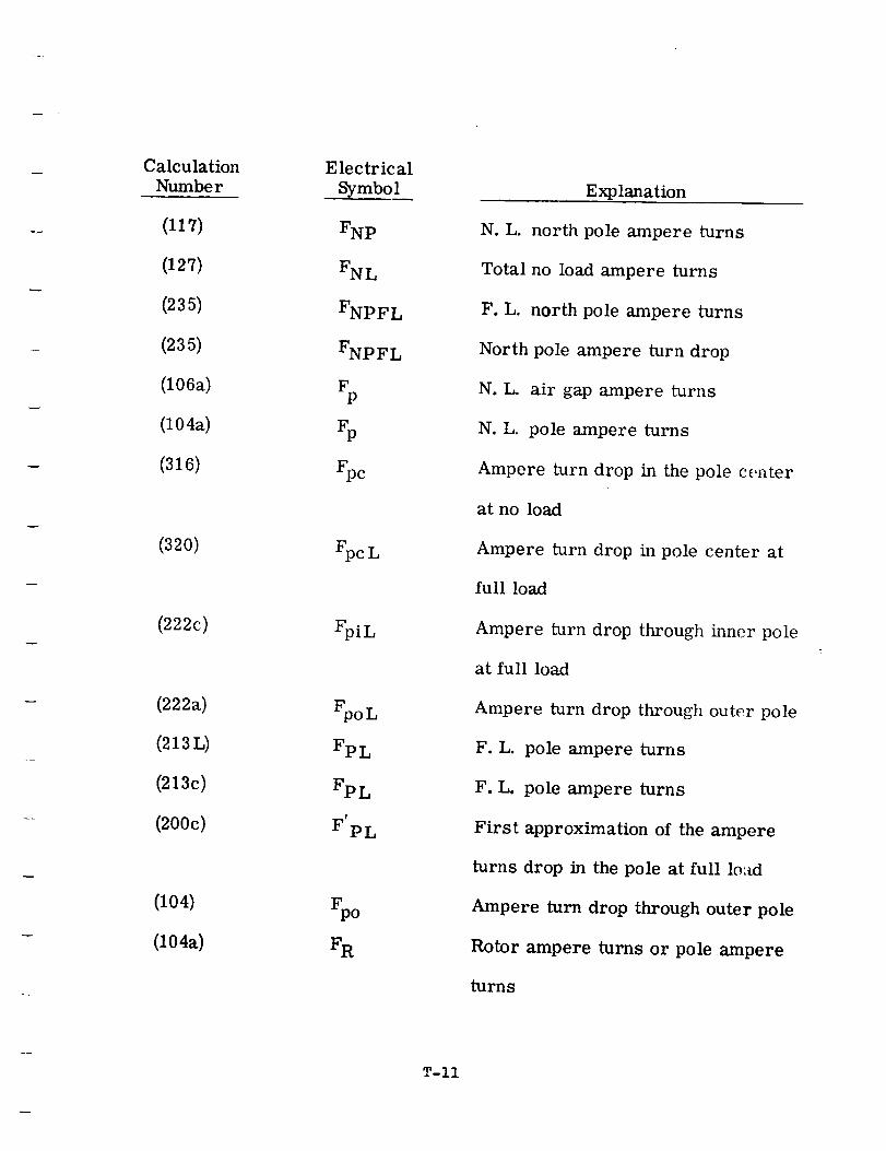
Calculation
Number
(117)
(127)
(235)
(235)
(106a)
(104a)
(316)
(320)
(222c)
(222a)
(213L)
(213c)
(200c)
(104)
(104a)
Electrical
Symbol
FNp
FNL
FNPFL
FNPFL
FP
Fp
FpcL
FpiL
FpoL
FpL
Fp L
F'pL
Explanation
N.L. north pole ampere turns
Total no load ampere turns
F.L. north pole ampere turns
North pole ampere turn drop
N.L. air gap ampere turns
N.L. pole ampere turns
Ampere turn drop in the pole center
at no load
Ampere turn drop in pole center at
full load
Ampere turn drop through inner pole
at full load
Ampere turn drop through outer pole
F. L. pole ampere turns
F.L. pole ampere turns
First approximation of the ampere
turns drop in the pole at full lo:_d
Ampere turn drop through outer pole
Rotor ampere turns or pole ampere
turns
T-If
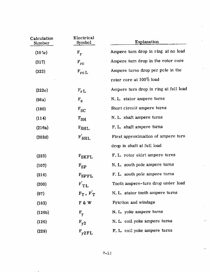
Calculation
Number
(1O',e)
(317)
(322)
(222e)
(98a)
(180)
(114)
(216a)
(202d)
(223)
(107)
(216)
(200)
(97)
(183)
(126b)
(126)
(229)
Electrical
Symbol
Fr
FrcL
FrL
F s
FSC
FSH
FSHL
I
F SHL
FSKFL
FSp
FSp FL
F'TL
t
F T , FT
F&W
Fy
Fy2
Fy2FL
Explanation
Ampere turn drop in ring at no load
Ampere turn drop in the rotor core
Ampere turns drop per pole in the
rotor core at 100% load
Ampere turn drop in ring at full load
N.L. stator ampere turns
Short circuit ampere turns
N.L. shaft ampere turns
F.L. sha/t ampere turns
First approximation of ampere turn
drop in shaft at full load
F.L. rotor skirt ampere turns
N.L. south pole ampere turns
F.L. south pole ampere turns
Tooth ampere-turn drop under load
N.L. stator tooth ampere turns
Friction and windage
N.L. yoke ampere turns
N.L. coil yoke ampere turns
F.L. coil yoke ampere turns
T-12
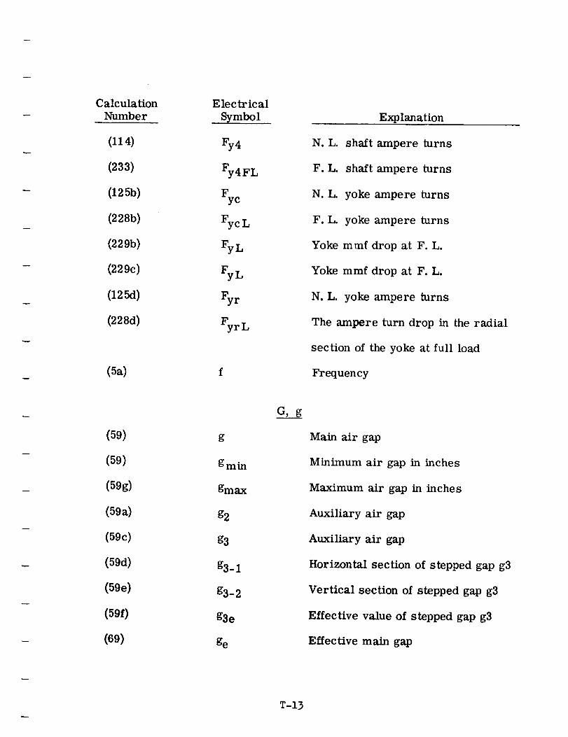
Calculation
Number
(114)
(233)
(1255)
(2285)
(229b)
(229c)
(125d)
(228d)
(5a)
Electrical
Symbol
Fy4FL
5cFycL
FyL
FyLFyr
FyrL
Explanation
N. L.
F.L.
N.L.
F.L.
shaft ampere turns
shaft ampere turns
yoke ampere turns
yoke ampere turns
Yoke mmf drop at F. L.
Yoke mmf drop at F. L.
N.L. yoke ampere turns
The ampere turn drop in the radial
section of the yoke at full load
Frequency
(59)
(59)
(59g)
(59a)
(59c)
(59d)
(59e)
(59f)
(69)
g
groin
gmax
g2
g3
g3-1
g3-2
g3e
ge
G, g
Main air gap
Minimum air gap in inches
Maximum air gap in inches
Auxiliary air gap
Auxiliary air gap
Horizontal section of stepped gap g3
Vertical section of stepped gap g3
Effective value of stepped gap g3
Effective main gap
T-13
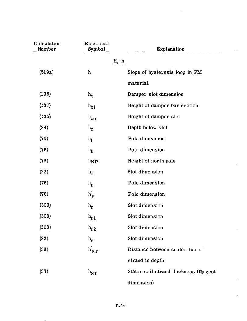
Calculation
Number
(519a)
(135)
(137)
(135)
(24)
(76)
(76)
(78)
(22)
(76)
(76)
(303)
(303)
(303)
(22)
(38)
(37)
E lectrical
Symbol
h
%1
he
hh
hNp
ho
f
hp
h s
I
hST
hST
H, h
Explanation
Slope of hysteresis loop in PM
material
Damper slot dimension
Height of damper bar section
Height of damper slot
Depth below slot
Pole dimension
Pole dimension
Height of north pole
Slot dimension
Pole dimension
Pole dimension
Slot dimension
Slot dimenslon
Slot dimenslon
Slot dimension
Distance between center line ,:
strand in depth
Stator coil strand thickness (largest
dimension)
T-14
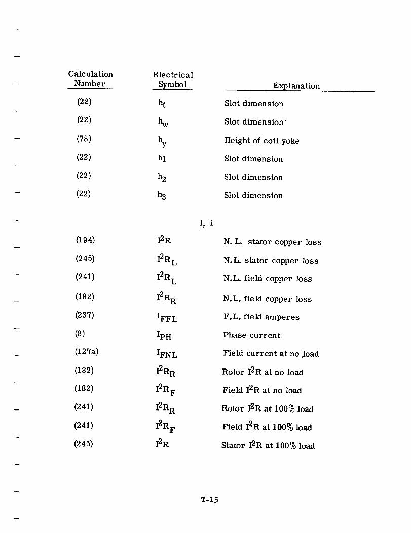
Calculation
Number
(22)
(22)
(78)
(22)
(22)
(22)
(194)
(245)
(241)
(182)
(237)
(8)
(127a)
(182)
(182)
(241)
(241)
(245)
Electrical
Symbol
ht
hw
hl
h2
h3
I2R
I2R L
I2R L
I2R R
IFFL
Ipn
IFNL
I2R R
I2R F
I2R R
I2R F
I2R
i,i
T-15
Explanation
Slot dimension
Slot dimension
Height of coil yoke
Slot dimension
Slot dimension
Slot dimension
N.L. stator copper loss
N.L. stator copper loss
N.L. field copper loss
N.L. field copper loss
F.L. field amperes
Phase current
Field current at no ,load
Rotor I2R at no load
Field I2R at no load
Rotor I2R at 100% load
Field I2R at 100% load
Stator I2R at 100% load
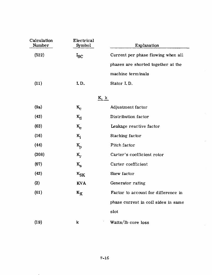
CalculationNumber
(522)
(11)
(9a)
(43)
(63)
(16)
(44)
(308)
(67)
(42)
(2)
(61)
(19)
Electrical
Symbol
ISC
LD.
Kc
Ka
Ke
%
Ks
KSK
KVA
Kx
k
K, k
Explanation
Current per phase flowing when all
phases are shorted together at the
machine terminals
Stator I.D.
Adjustment factor
Distribution factor
Leakage reactive factor
Stacking factor
Pitch factor
Carter's coefficient rotor
Carter coefficient
Skew factor
Generator rating
Factor to account for difference in
phase current in coil sides in same
slot
Watts/lb core loss
T-16
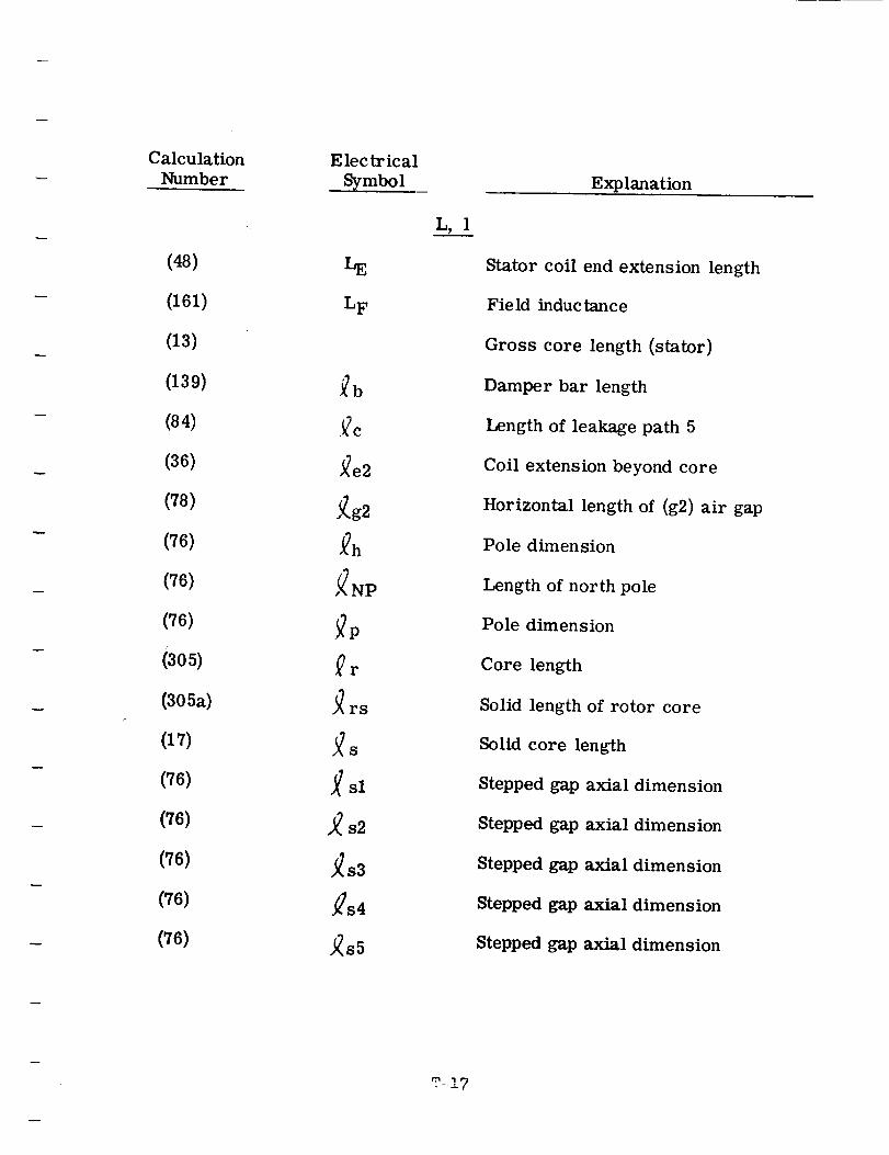
Calculation
Number
(48)
(161)
(13)
(139)
(84)
(36)
(78)
(76)
(76)
(76)
(305)
(305a)
(17)
(76)
(76)
(76)
(76)
(76)
Electrical
Symbol
LE
LF
_b
._c
J_e2
].g2
,_NP
_r
_rs
sl
._ s2
_83
,_s4
,(s5
L, 1
T-,17
Explanation
Stator coil end extension length
Field inductance
Gross core length (stator)
Damper bar length
Length of leakage path 5
Coil extension beyond core
Horizontal length of (g2) air gap
Pole dimension
Length of north pole
Pole dimension
Core length
Solid length of rotor core
Solid core length
Stepped gap axial dimension
Stepped gap axial dimension
Stepped gap axial dimension
Stepped gap axial dimension
Stepped gap axial dimension
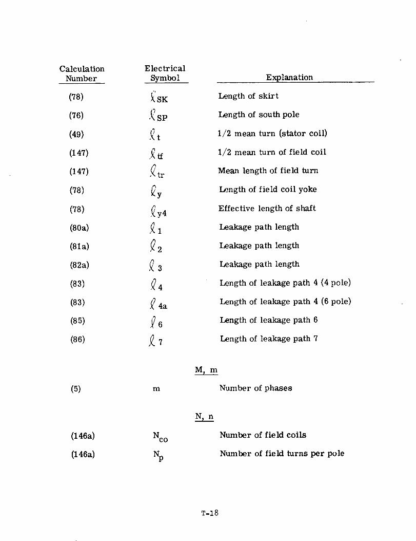
Calculation
Number
(78)
(76)
(49)
(147)
(147)
(78)
(78)
(80a)
(81a)
(82a)
(83)
(83)
(85)
(86)
Electrical
Symbol
k'SK
•_ SP
,_t
,_tr
,_y4
.Q4
,_4a
Explanation
Length of skirt
Length of south pole
1/2 mean turn (stator coil)
1/2 mean turn of field coil
Mean length of field turn
Length of field coil yoke
Effective length of shaft
Leakage path length
Leakage path length
Leakage path length
Length of leakage path 4 (4 pole)
Length of leakage path 4 (6 pole)
Length of leakage path 6
Length of leakage path 7
(5) m
M,m
Number of phases
(146a)
(146a)
Nco Number of field coils
Number of field turns per pole
T-18
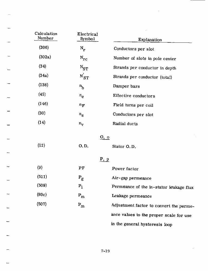
Calculation
Number
(306)
(302a)
(34)
(34a)
(138)
(45)
(146)
(30)
(14)
(12)
(9)
(511)
(509)
(80c)
(507)
Electrical
Symbol
N r
_c
NST
T
NST
%
n e
n F
n S
n V
O. D.
PF
Pg
Pi
Pm
Pm
O,o
Explanation
Conductors per slot
Number of slots in pole center
Strands per conductor in depth
Strands per conductor (total)
Damper bars
Effective conductors
Field turns per coil
Conductors per slot
Radial ducts
Stator O.D.
Power factor
Air- gap permeance
Permeance of the in-stator leakage flux
Leakage permeance
Adjustment factor to convert the perme-
ance values to the proper scale for use
in the general hysteresis loop
T-19
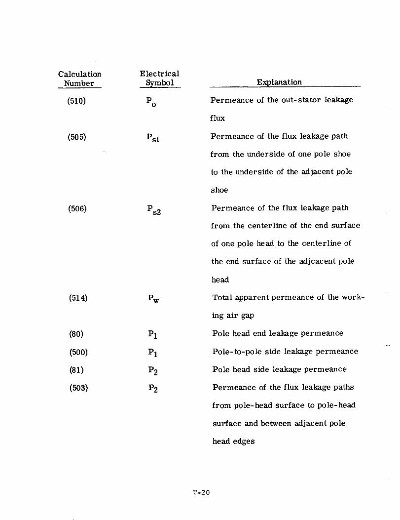
Calculation
Number
(51o)
(505)
(506)
(514)
(80)
(500)
(81)
(503)
Electrical
Symbol
Po
Psi
Ps2
Pw
Pl
Pl
P2
P2
Explanation
Permeance of the out-stator leakage
flux
Permeance of the flux leakage path
from the underside of one pole shoe
to the underside of the adjacent pole
shoe
Permeance of the flux leakage path
from the centerline of the end surface
of one pole head to the centerline of
the end surface of the adjcacent pole
head
Total apparent permeance of the work-
ing air gap
Pole head end leakage permeance
Pole-to-pole side leakage permeance
Pole head side leakage permeance
Permeance of the flux leakage paths
from pole-head surface to pole-head
surface and between adjacent pole
head edges
T-20
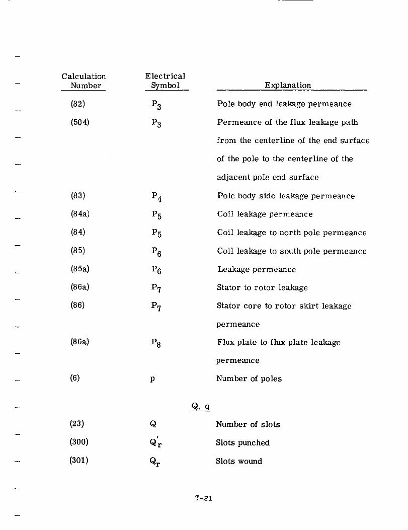
Calculation
Number
(82)
(504)
(83)
(84a)
(84)
(85)
(85a)
(86a)
(86)
(86a)
(6)
(23)
(300)
(301)
Electrical
Symbol
P3
P3
P4
P5
P5
P6
P6
P7
P7
P8
P
Q
Qr
Qr
Q, q
T-21
Explanation
Pole body end leakage permeance
Permeance of the flux leakage path
from the centerline of the end surface
of the pole to the centerline of the
adjacent pole end surface
Pole body side leakage permeance
Coil leakage permeance
Coil leakage to north pole permeance
Coil leakage to south pole permeance
Leakage permeance
Stator to rotor leakage
Stator core to rotor skirt leakage
permeance
Flux plate to flux plate leakage
permeance
Number of poles
Number of slots
Slots punched
Slots wound
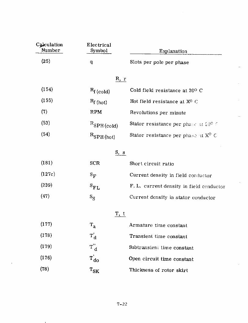
C_culationNumber
(25)
(154)
(155)
(7)
(53)
(54)
(181)
(127c)
(239)
(47)
(177)
(178)
(179)
(176)
(78)
E lec tr ical
Symbol
q
Rf (cold)
Rf (hot)
RPM
RSPH (cold)
RSPH (hot)
SCR
S F
SFL
S S
Wa
%
W'_!
Td o
TSK
a_ r
S, s
T, t
Explanation
Slots per pole per phase
Cold field resistance at 20 ° C
Hot field resistance at XO C
Revolutions per minute
Stator resistance per pha:__,: ::_, _0 e :-
Stator resistance per pha:-:., _t k-° C
Short circuit ratio
Current density in field coIMu ctor
F.L. current density in fietd conductor
Current density in stator conductor
Armature time constant
Transient time constant
Subtransien{ time constant
Open circuit time constant
Thickness of rotor skirt
T-22
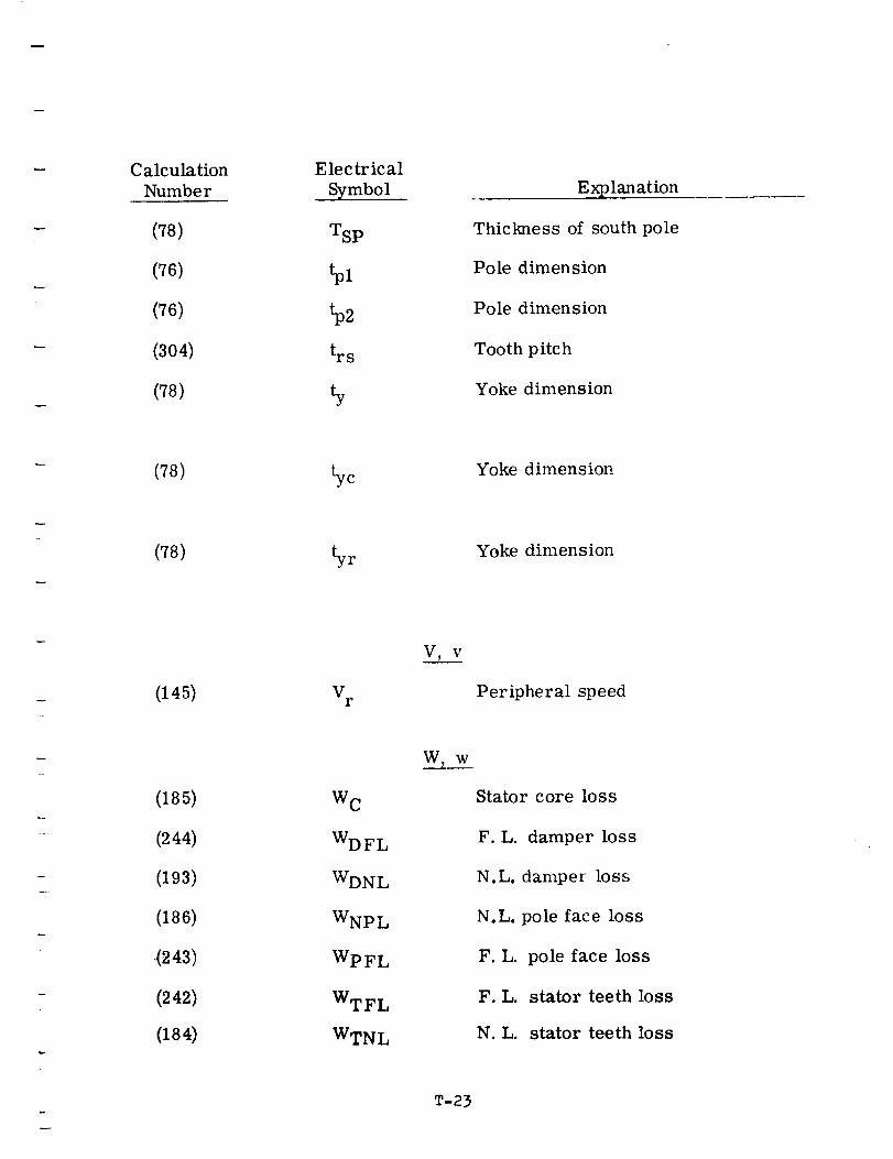
w
b
Calculation
Number
(78)
(76)
(76)
(304)
(78)
(78)
(78)
(145)
(185)
(244)
(193)
(186)
(243)
(242)
(184)
Electrical
Symbol
TSp
_s
tyc
yr
V r
W C
WDFL
WDNL
WNp L
WpFL
WTFL
WTNL
V) V
W_ W
T-23
Explanation
Thickness of south pole
Pole dimension
Pole dimension
Tooth pitch
Yoke dimension
Yoke dimension
Yoke dimension
Peripheral speed
Stator core loss
F.L. damper loss
N.L. damper loss
N.L. pole face loss
F.L.
F.L.
N.L.
pole face loss
stator teeth loss
stator teeth loss
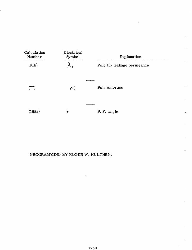
Calculation Elec tr icalNumber Symbol
(81b) /_t
Explanation
Pole tip leakage permeance
(77) _ Pole embrace
(198a) 0 P.F. angle
PROGRAMMING BY ROGER W. HULTHEN.
rm -30
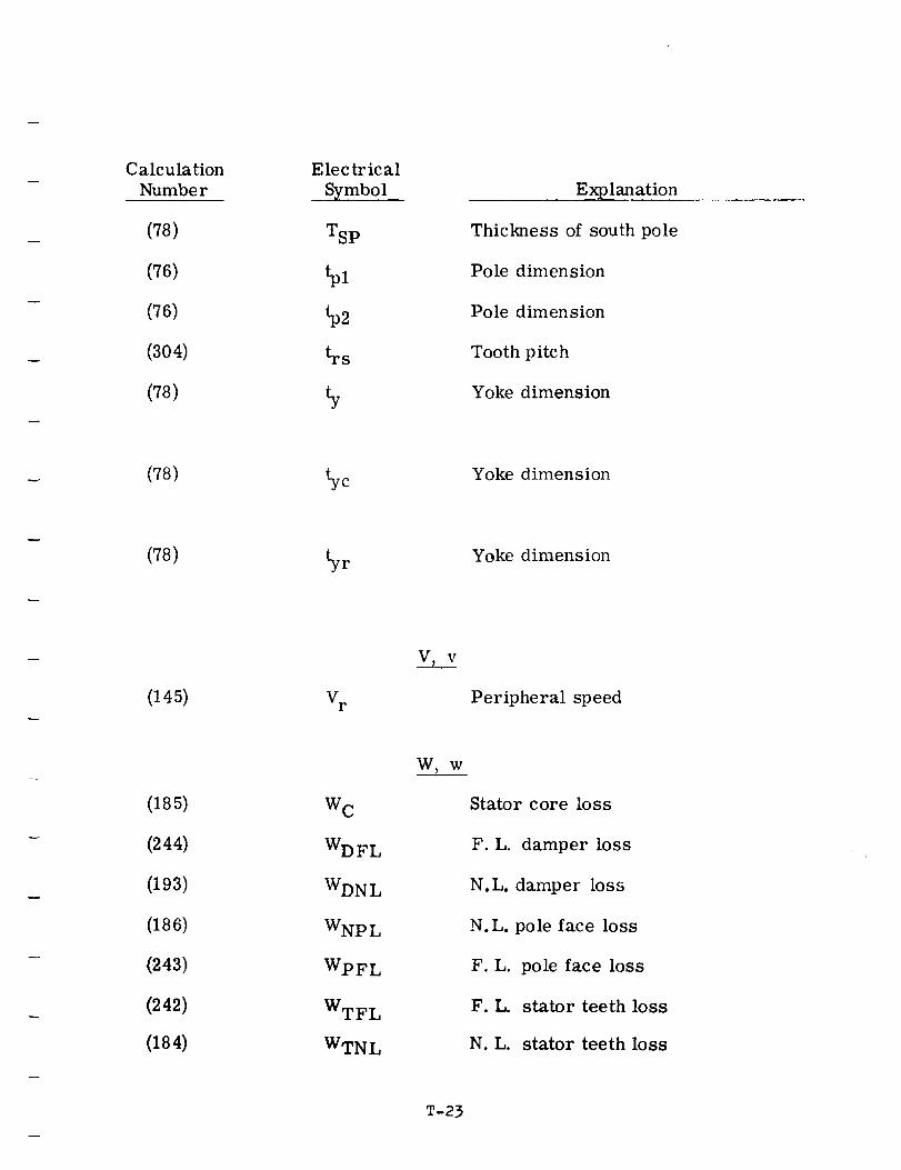
Calculation
Number
(78)
(76)
(76)
(304)
(78)
(78)
(78)
(145)
(185)
(244)
(193)
(186)
(.243)
(242)
(184)
Electrical
Symbol
TSp
_s
yr
V r
W C
WDFL
WDNL
WNp L
WpFL
WTFL
WTNL
V_ v
W,w
Explanation
Thickness of south pole
Pole dimension
Pole dimension
Tooth pitch
Yoke dimension
Yoke dimension
Yoke dimension
Peripheral speed
Stator core loss
F.L. damper loss
N.L. damper loss
N.L. pole face loss
F. L.
F.L.
N.L.
pole face loss
stator teeth loss
stator teeth loss
T-23
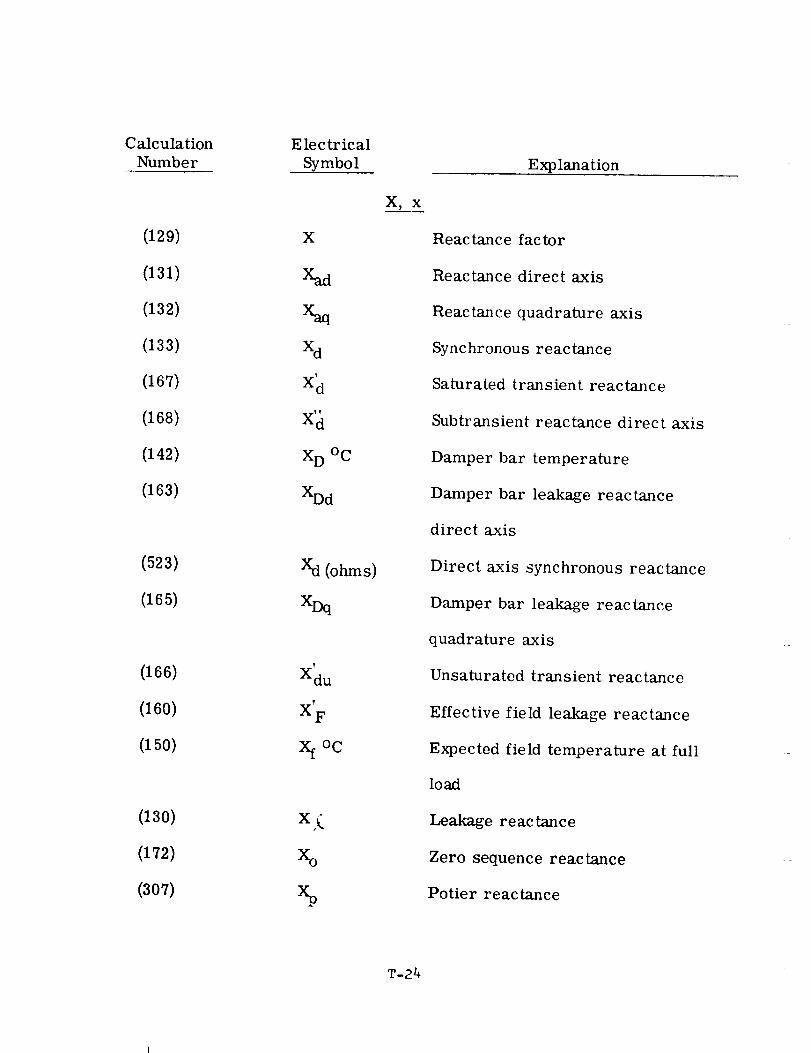
Calculation
Number
(129)
(131)
(132)
(133)
(167)
(168)
(142)
(163)
(523)
(165)
(166)
(160)
(150)
(130)
(172)
(307)
Electrical
Symbol
X
X_d
Xd
X'd
X D °C
XDd
Xd (ohms)
XDq
T
Xdu
X F
xfoc
x(
Xo
X_ x
Explanation
Reactance factor
Reactance direct axis
Reactance quadrature axis
Synchronous reactance
Saturated transient reactance
Subtransient reactance direct axis
Damper bar temperature
Damper bar leakage reactance
direct axis
Direct axis synchronous reactance
Damper bar leakage reactance
quadrature axis
Unsaturated transient reactance
Effective field leakage reactance
Expected field temperature at full
load
Leakage reactance
Zero sequence reactance
Potier reactance
T-24
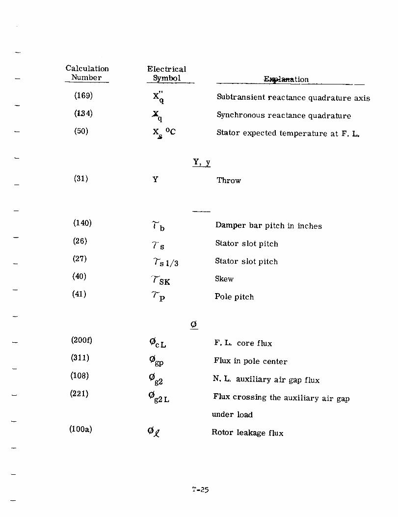
Calculation
Number
(169)
(134)
(50)
Electrical
• .Symbol
X"q
xnX °C
E_a_ation
Subtransient reactance quadrature axis
Synchronous reactance quadrature
Stator expected temperature at F. L.
(31) Y
Y, Y
Throw
(140)
(26)
(27)
(40)
(41)
Ib
Is
_sl/3
"'rS K
%
Damper bar pitch in inches
Stator slot pitch
Stator slot pitch
Skew
Pole pitch
(200f)
(311)
(108)
(221)
(lOOa)
Oc L
_gp
Og2
Og2L
F.L. core flux
Flux in pole center
N.L. auxiliary air gap flux
Flux crossing the auxiliary air gap
under load
Rotor leakage flux
T-25
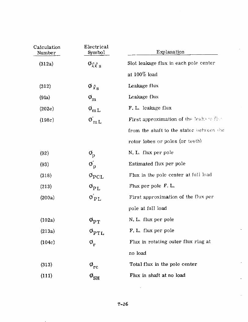
Calculation
Number
(312a)
(312)
(91a)
(202e)
(198c)
(92)
(93)
(318)
(213)
(200a)
(102a)
(213a)
(104c)
(313)
(111)
Electrical
Symbol
O_s
Om
OmL
O'mL
O,P
OPCL
OPL
OpL
OpT
OPTL
O r
(_rc
OSH
Explanation
Slot leakage flux in each pole center
at 100% load
Leakage flux
Leakage flux
F.L. leakage flux
First approximation of th,: _eak,-_ :_::- Fi'.-
from the shaft to the stator i)et_e_r_ _e
rotor lobes or poles (or teeth)
N.L. flux per pole
Estimated flux per pole
Flux in the pole center at full load
Flux per pole F. L.
First approximation of the flux per
pole at full load
N.L. flux per pole
F.L. flux per pole
Flux in rotating outer flux ring at
no load
Total flux in the pole center
Flux in shaft at no load
T-26
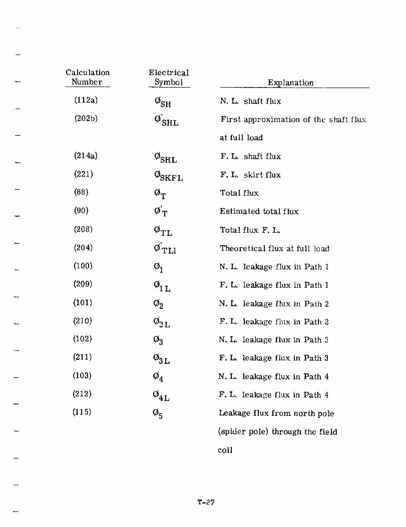
Calculation
Number
(l12a)
(2025)
(214a)
(221)
(88)
(90)
(208)
(204)
(100)
(209)
(101)
(210)
(102)
(211)
(103)
(212)
(115)
Electrical
Symbol
0SH
0SHL
0SHL
0SKFL
0 T
0'T
0TL
0'TL 1
01
01L
02
02 L
03
03L
04
04L
05
Explanation
N.L. shaft flux
First approximation of the shaft flux
at full load
F.L. shaft flux
F.L. skirt flux
Total flux
Estimated total flux
Total flux F. L.
Theoretical flux at full load
N.L. leakage flux in Path 1
F.L. leakage flux in Path 1
N.L. leakage flux in Path 2
F.L. leakage flux in Path 2
N.L. leakage flux in Path 3
F.L. leakage flux in Path 3
N.L. leakage flux in Path 4
F.L. leakage flux in Path 4
Leakage flux from north pole
(spider pole) through the field
coil
T-27
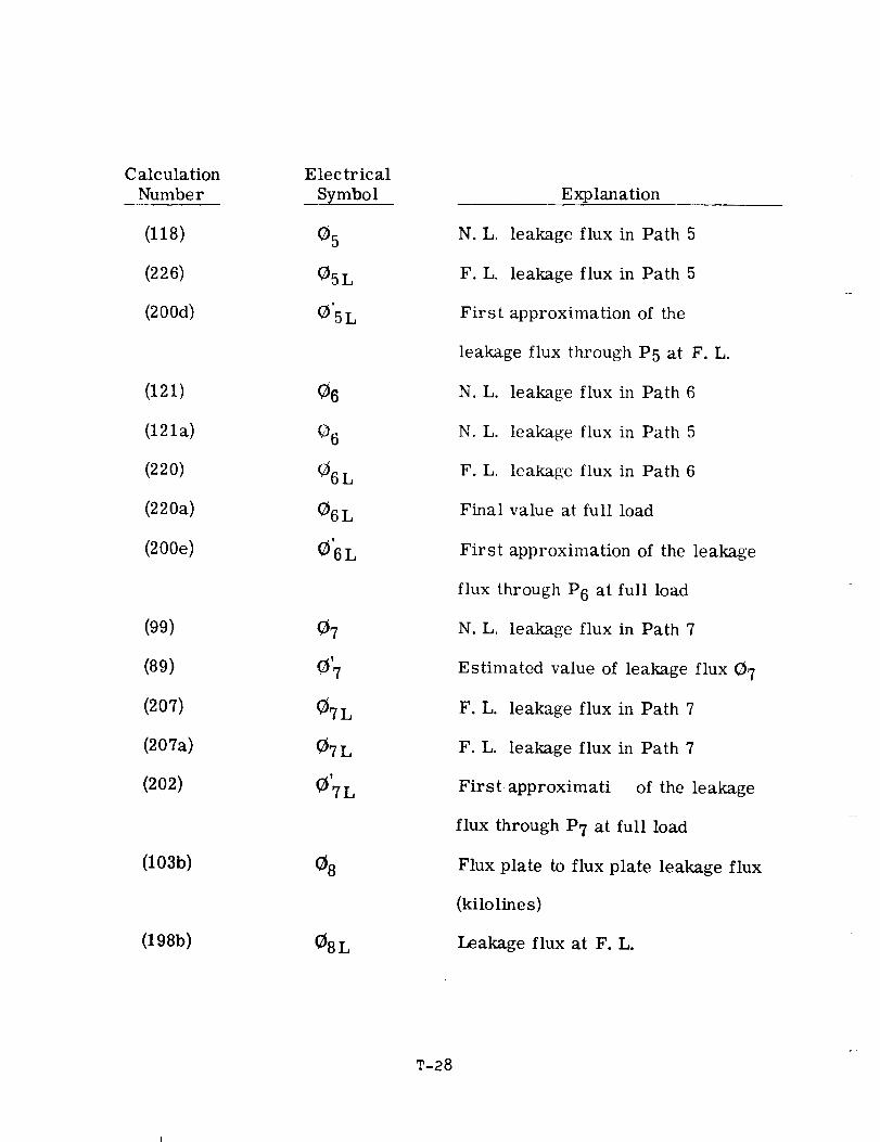
Calculation
Number
(118)
(226)
(200d)
(121)
(121a)
(220)
(220a)
(200e)
(99)
(89)
(207)
(207a)
(202)
(103b)
(19Sb)
Electrical
Symbol
05
05L
O'5L
06
O6
(36L
06L
06L
07
{3'7
07L
07L
_'7L
_8L
Explanation
N.L. leakage flux in Path 5
F.L. leakage flux in Path 5
First approximation of the
leakage flux through P5 at F. L.
N.L. leakage flux in Path 6
N.L. leakage flux in Path 5
F.L. leakage flux in Path 6
Final value at full load
First approximation of the leakage
flux through P6 at full load
N.L. leakage flux in Path 7
Estimated value of leakage flux (37
F.L. leakage flux in Path 7
F.L. leakage flux in Path 7
First approximati of the leakage
flux through P7 at full load
Flux plate to flux plate leakage flux
(kilolines)
Leakage flux at F. L.
T-28
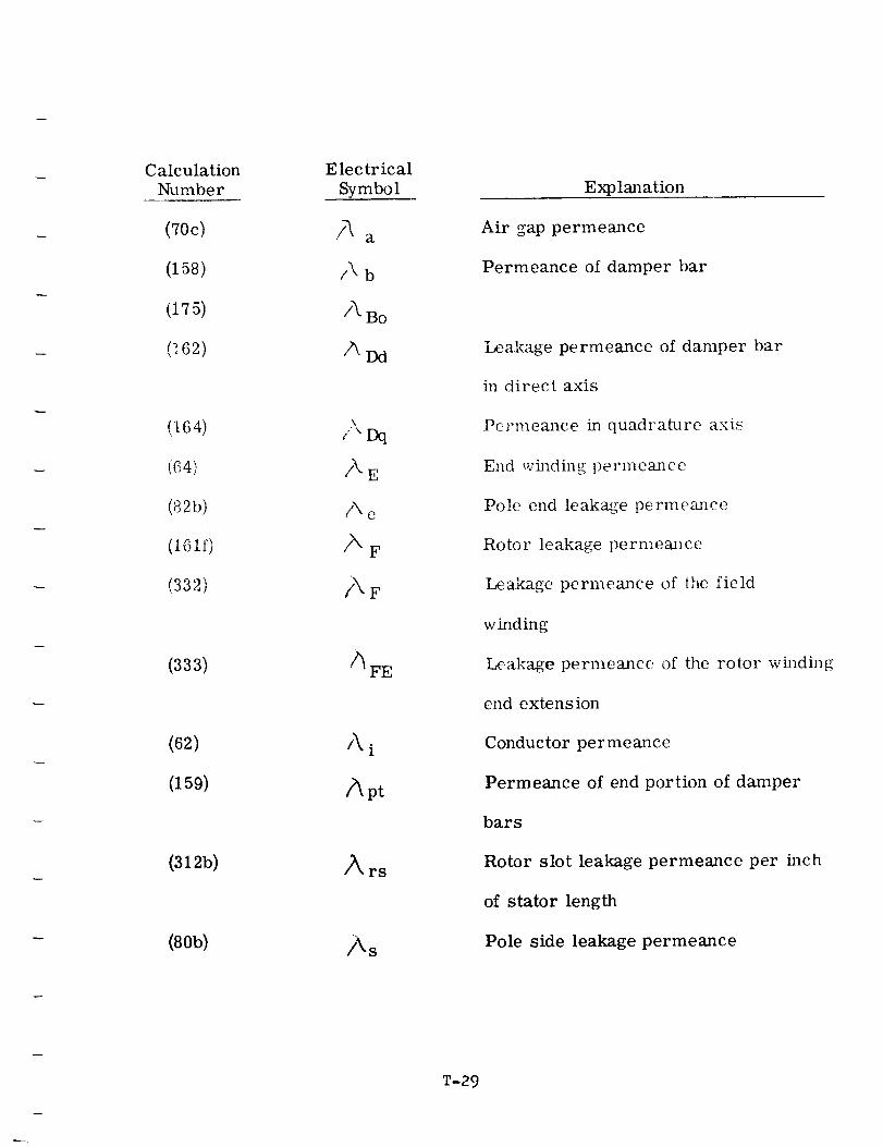
Calculation
Number
(70c)
(158)
(175)
(162)
(164)
(64)
(_2b)
(ioif)
(332)
(333)
(62)
(159)
(312b)
(80b)
Electrical
Symbol
A a
/\ b
/\ Bo
ADd
/'Dq
AE
Ae
AF
/_pt
Ars
As
Explanation
Air gap permeance
Permeance of damper bar
Leakage permeance of damper bar
in direct axis
Permeance in quadrature axis
End winding permeance
Pole end leakage permeance
Rotor leakage permemlce
Leakage permeance of the field
winding
Leakage permeance of the rotor winding
end extension
Conductor permeance
Permeance of end portion of damper
bars
Rotor slot leakage permeance per inch
of stator length
Pole side leakage permeance
T-29
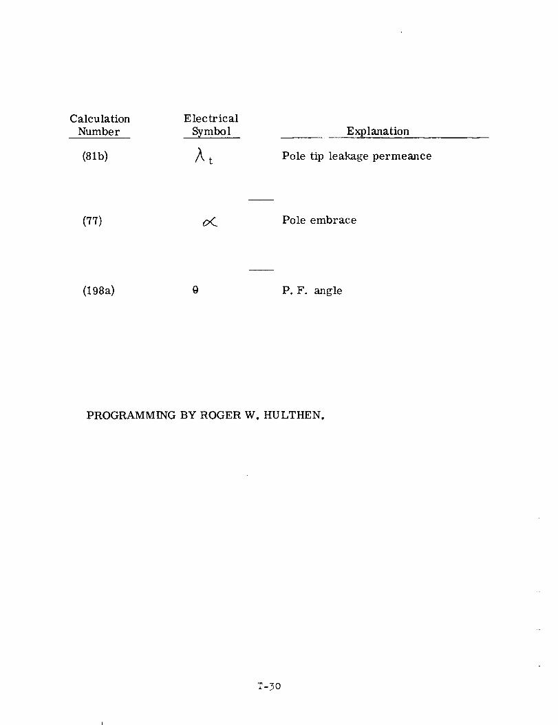
Calculation E lec tr ical
Number Symbol
(81b) _ t
Explanation
Pole tip leakage permeance
m
(77) _._ Pole embrace
(198a) @ P.F. angle
PROGRAMMING BY ROGER W. HULTHEN.
T-30


![Brushless Wound-Rotor [Synchronous] Doubly-Fed Electric ...bestelectricmachine.com/wp-content/uploads/2019/07/Sensorless_BWRSDF.pdfcircular rotating transformers to at least replace](https://img.pdfslide.us/doc/110x75/5e7957a96f06eb6a022c3253/brushless-wound-rotor-synchronous-doubly-fed-electric-circular-rotating-transformers.jpg)