Embed Size (px)
Citation preview

Topic No. 600-000-002Basis of Estimates
2014 EditionApril 29, 2015
630- 2- AB CONDUIT
Unit LF; M1 Accuracy Linear Foot; 1/10 Meter PlanQuantity? no
January 2015: See updated guidance for Plan Summary Boxes
This item is valid for signals, lighting, and other electrically powered or operated devices.For each run of conduit, the call-out in the plans must show the pay item, # of runs, and the length of the run. The default diameter is 2" ; all other diameters should be noted in the call-out. For example, 630-2-11 (2 runs of 4" @100'), or 630-2-11 (2 runs @ 90').
MEASUREMENT- TRENCH or BORE: Measurement is for the straight line HORIZONTAL DISTANCE of the trench or bore, from pull box to pull box, with no allowance for sweeps or vertical distance. No additional payment will be made for multiple runs of conduit within a trench or bore.
MEASUREMENT- ABOVEGROUND or BRIDGE MOUNT: Measurement will be for the actual length of conduit used.
REMOVAL: Removal will be paid for bridge mount option only. Aboveground conduit will be incidental to pole or equipment removal All other below ground conduit will remain in place, or be incidental to clearing and grubbing.********************B=1 OPEN TRENCH is used when box-to-box length is underground, and can be open trenched. If the contractor chooses to use an alternate method, payment will remain "open trench".
*************************PLAN SUMMARY FORMS: Tabulate the pay item on the appropriate Signals or Lighting tabulation sheet(s).Summary of General Items summary box may be used for sidewalk repairs only when component plans for signals or lighting do not exist.
Required Recommended
Standards
Specifications
Details
Related Items
Design Forms and Documentation
PPM Chapter
Notes
References
COMP 700-050-03: Linear Measurement, Component Weight, Per Hour, Per Day or Per Each Computation and Continuation
Locate in the plans. Summarize quantities by location in the computation book.
Trns·port
TRNS*PORT Category (DRAFT FIELD): Multiple Roadway, Signals, Lighting, etc
Other
Construction Forms and Documentation
Plan Summary Box
Multiple: Multiple forms may be applicable. See details above.
Refer to BOE details for project application.
NOTE: Design Forms and Construction forms below are associated with Comp Book Projects. Refer to Chapter 8 for details.
Page 1 of 157Details and Structure: Items 600 to 699

Topic No. 600-000-002Basis of Estimates
2014 EditionApril 29, 2015
Struct. 630- 2- AB CONDUIT LF
A = Operation1 (Furnish & Install)6 (Remove) B= 5 only, effective July 2014
B = Installation Method/location- see details above1 (open trench) Underground *2 (Directional Bore) Underground or Underpavement*3 (Jack & Bore) Typically under railroad*4 (Aboveground)**5 (Bridge Mount)**
*Measured as the horizontal length of the trench or bore; no additional payment for multiple conduits in trench. **Measured as the actual length of each conduit.
Notes
The following items were open, as of the publication date. Refer to the Master Pay Item list for current items. Additional items may be opened upon request.
Item Description Unit TSP/Detail Valid Date Obsolete Date
0630 2 11 CONDUIT, FURNISH & INSTALL, OPEN TRENCH
LF 7/1/2013
0630 2 12 CONDUIT, FURNISH & INSTALL, DIRECTIONAL BORE
LF 7/1/2013
0630 2 13 CONDUIT, FURNISH & INSTALL, JACK & BORE UNDER RAILROAD
LF 5/1/2015 5/30/2015
0630 2 14 CONDUIT, FURNISH & INSTALL, ABOVEGROUND
LF 7/1/2013
0630 2 15 CONDUIT, FURNISH & INSTALL, BRIDGE MOUNT
LF 7/1/2013
0630 2 65 CONDUIT, REMOVE, BRIDGE MOUNT LF 7/1/2013
Page 2 of 157Details and Structure: Items 600 to 699

Topic No. 600-000-002Basis of Estimates
2014 EditionApril 29, 2015
632- 7- A SIGNAL CABLE
Unit Mixed Accuracy Refer to item structure and details
PlanQuantity? no
This pay item is for traffic control devices, including traffic signals and ITS devices.
Includes cable, support wire, cable ties, cable clamps, lashing wire, terminal connectors and cable grounding, within the normal limits of the intersection. May include total intersection replacement, and/or pedestrian signals, as noted in the plans.
CURRENT TEXT ***************************
Effective January 2014:For New or Reconstructed Intersections, use the per Intersection pay item. This includes intersections where new poles are installed/relocated. (Payment per intersection will include varying lengths by project, based on locations shown in the plans.)
For Repairs/Replacement/Other operations where new signal cable is needed, use the linear foot pay item. This includes non-intersection school zone signals, adding a signal head to an existing mast arm or span wire, or signal cables outside of an intersection. This item is also used by Maintenance, where plans/locations may not be available prior to bid.
REMOVE: Payment includes all signal cable per intersection, or per LF for other applications, such as between a controller and flashing beacon sign(s). Detail quantity/location in the plans.
OLD TEXT *******************************
For projects let through June 2013, consider 632- 6- (2632- 6-) for runs outside the limits of the intersection.
For projects let July 2013 through December 2013, pay item 632-7-2 is available for Repair/Replace/Other installations, but will require plan details or modified specification. An update to specification section 632 is pending for January 2014.
Required Recommended
Standards Index No. 17727
Normally requires SHOP DRAWINGS
Details
Record final quantity on the tabulation sheet (plans) or computation form (comp book).
Related Items
Design Forms and Documentation
PPM Chapter
Notes
References
tabqsg: Signalization Tabulation of Quantity Sheet
Locate in plans. Summarize quantities by location on summary sheet in the plans.
No additional form required; use plans summary or comp book
Trns·port
Other
Construction Forms and Documentation
Plan Summary Box
Signalization: Tabulation of Quantities
Summarize items by pay item and location.
NOTE: Design Forms and Construction forms below are associated with Comp Book Projects. Refer to Chapter 8 for details.
Page 3 of 157Details and Structure: Items 600 to 699

Topic No. 600-000-002Basis of Estimates
2014 EditionApril 29, 2015
Specifications Section 632
http://www.dot.state.fl.us/specificationsoffice/Implemented/SpecBooks
Struct. 632- 7- A SIGNAL CABLE Mixed
A = Operation1 (New or Reconstructed Intersection- Furnish & Install) PI2 (Repair, Replacement, and other operations- Furnish & Install) LF 4 (Adjust/Modify) PI6 (Remove- Intersection) PI effective July 20147 (Remove- Outside of Intersection) LF effective July 2014
Notes
TRNS*PORT Category (DRAFT FIELD): 0500 Signalization (or ITS)
The following items were open, as of the publication date. Refer to the Master Pay Item list for current items. Additional items may be opened upon request.
Item Description Unit TSP/Detail Valid Date Obsolete Date
0632 7 1 SIGNAL CABLE‐ NEW OR RECONSTRUCTED INTERSECTION, FURNISH & INSTALL
PI 1/1/2013
0632 7 2 SIGNAL CABLE‐ REPAIR/REPLACE/OTHER, FURNISH & INSTALL
LF 1/1/2013
0632 7 4 SIGNAL CABLE, ADJUST PI 1/1/2013
0632 7 6 SIGNAL CABLE, REMOVE‐ INTERSECTION PI P 7/1/2014
0632 7 7 SIGNAL CABLE, REMOVE‐ OUTSIDE OF INTERSECTION
LF P 7/1/2014
Page 4 of 157Details and Structure: Items 600 to 699

Topic No. 600-000-002Basis of Estimates
2014 EditionApril 29, 2015
633- 1-ABC FIBER OPTIC CABLE
Unit LF; M1 Accuracy Linear Foot; 1/10 Meter PlanQuantity? no
For use in fiber optic networks that support ITS devices and their connection to communication hubs, transportation management centers, and related facilities. Use "overhead" for installations involving bridges and other aboveground structures. Use "underground" for cable placed in buried conduit along the roadside.
Required Recommended
Standards
Specifications
Vol 1, Chapter 7
Struct. 633- 1-ABC FIBER OPTIC CABLE LF
A= Operation1 (Furnish & Install)3 (Install) Furnished by FDOT or local agency; C=04 (Relocate) C=06 (Remove) C=0; effective July 2014; through 6/2014, see 690 removal items
B= Location1 (Overhead)2 (Underground)
C= Number of Fibers in Cable1 (2 to 12)2 (13 to 48)3 (49 to 96)4 (97 to 144)
Notes *Remove item may require plan details and/or tech spec
T: Plan Details and/or Technical Specifications required
Details
Record final quantity on the tabulation sheet (plans) or computation form (comp book).
Related Items
Design Forms and Documentation
PPM Chapter
Notes
References
tabqsg: Signalization Tabulation of Quantity Sheet
Locate in plans. Summarize quantities by location on summary sheet in the plans.
No additional form required; use plans summary or comp book
Trns·port
TRNS*PORT Category (DRAFT FIELD): 0500 Signalization (or ITS)
The following items were open, as of the publication date. Refer to the Master Pay Item list for current items. Additional items may be opened upon request.
Other
Construction Forms and Documentation
Plan Summary Box
Signalization: Tabulation of Quantities
Summarize items by pay item and location.
NOTE: Design Forms and Construction forms below are associated with Comp Book Projects. Refer to Chapter 8 for details.
Page 5 of 157Details and Structure: Items 600 to 699

Topic No. 600-000-002Basis of Estimates
2014 EditionApril 29, 2015
Item Description Unit TSP/Detail Valid Date Obsolete Date
0633 1111 FIBER OPTIC CABLE, F&I, OVERHEAD,2‐12 FIBERS
LF 1/1/2013
0633 1112 FIBER OPTIC CABLE, F&I, OVERHEAD,13‐48 FIBERS
LF 1/1/2013
0633 1113 FIBER OPTIC CABLE, F&I, OVERHEAD,49‐96 FIBERS
LF 1/1/2013
0633 1114 FIBER OPTIC CABLE, F&I, OVERHEAD,97‐144 FIBERS
LF 1/1/2013
0633 1121 FIBER OPTIC CABLE, F&I, UNDERGROUND,2‐12 FIBERS
LF 1/1/2013
0633 1122 FIBER OPTIC CABLE, F&I, UNDERGROUND,13‐48 FIBERS
LF 1/1/2013
0633 1123 FIBER OPTIC CABLE, F&I, UNDERGROUND,49‐96 FIBERS
LF 1/1/2013
0633 1124 FIBER OPTIC CABLE, F&I, UNDERGROUND, 97 ‐ 144 FIBERS
LF 1/1/2013
0633 1320 FIBER OPTIC CABLE, INSTALL, UNDERGROUND
LF 1/1/2013
0633 1330 FIBER OPTIC CABLE, INSTALL, OVERHEAD LF 1/1/2013
0633 1410 FIBER OPTIC CABLE, RELOCATE, OVERHEAD LF 1/1/2013
0633 1420 FIBER OPTIC CABLE, RELOCATE, UNDERGROUND
LF 1/1/2013
0633 1610 FIBER OPTIC CABLE, REMOVE, OVERHEAD LF 7/1/2014
0633 1620 FIBER OPTIC CABLE, REMOVE, UNDERGROUND
LF 7/1/2014
Page 6 of 157Details and Structure: Items 600 to 699

Topic No. 600-000-002Basis of Estimates
2014 EditionApril 29, 2015
633- 2- AB FIBER OPTIC CONNECTION
Unit EA Accuracy Each PlanQuantity? no
For use in fiber optic networks where segments of fiber optic cable must be spliced together, or when cables must be terminated at the end of a segment. Note that each connection involves the fusing of individual optical fibers in a cable.
** Payment "each" is for each FIBER to be connected, i.e. 30 fibers in one cable= 30 connections.**
Type of connection must be noted in the plans.
Required Recommended 783-3
Standards
Specifications
http://www.dot.state.fl.us/specificationsoffice/Implemented/SpecBooks
Struct. 633- 2- AB FIBER OPTIC CONNECTION EA
New items for Signals use, pending spec approval.
A= Operation3 (Install)
B= Type1 (Splice)2 (Termination)
Notes
Details
Record final quantity on the tabulation sheet (plans) or computation form (comp book).
Related Items
Design Forms and Documentation
PPM Chapter
Notes
References
tabqsg: Signalization Tabulation of Quantity Sheet
Locate in plans. Summarize quantities by location on summary sheet in the plans.
No additional form required; use plans summary or comp book
Trns·port
TRNS*PORT Category (DRAFT FIELD): 0500 Signalization (or ITS)
The following items were open, as of the publication date. Refer to the Master Pay Item list for current items. Additional items may be opened upon request.
Other
Construction Forms and Documentation
Plan Summary Box
Signalization: Tabulation of Quantities
Summarize items by pay item and location.
NOTE: Design Forms and Construction forms below are associated with Comp Book Projects. Refer to Chapter 8 for details.
Item Description Unit TSP/Detail Valid Date Obsolete Date
0633 2 31 FIBER OPTIC CONNECTION, INSTALL, SPLICE EA 1/1/2013
0633 2 32 FIBER OPTIC CONNECTION, INSTALL, TERMINATION
EA 1/1/2013
Page 7 of 157Details and Structure: Items 600 to 699

Topic No. 600-000-002Basis of Estimates
2014 EditionApril 29, 2015
Page 8 of 157Details and Structure: Items 600 to 699

Topic No. 600-000-002Basis of Estimates
2014 EditionApril 29, 2015
633- 3- AB FIBER OPTIC CONNECTION HARDWARE
Unit EA Accuracy Each PlanQuantity? no
For use in fiber optic networks, where segments of cable must be spliced together.
Hardware items include incidental hardware and cables for a complete installation.
Hardware items furnished with additional cable, such as preterminated patch panels, include the installation of the cable. DO NOT provide additional payment for cable installation under cable or conduit items.
Required Recommended 783-2
Standards
Specifications
http://www.dot.state.fl.us/specificationsoffice/Implemented/SpecBooks
Struct. 633- 3- AB FIBER OPTIC CONNECTION HARDWARE EA
New items for Signals use, pending spec approval.
A= Operation1 (Furnish & Install)3 (Install)4 (Relocate)5 (Adjust /Modify)
B=Component1 (Splice Enclosure)2 (Splice Tray)3 (Preterminated Connector Assembly)4 (Buffer Tube Fan Out Kit)5 (Patch Panel, Preterminated)6 (Patch Panel, Field Terminated)7 (Connector Panel)
Notes
Details
Record final quantity on the tabulation sheet (plans) or computation form (comp book).
Related Items
Design Forms and Documentation
PPM Chapter
Notes
References
tabqsg: Signalization Tabulation of Quantity Sheet
Locate in plans. Summarize quantities by location on summary sheet in the plans.
No additional form required; use plans summary or comp book
Trns·port
TRNS*PORT Category (DRAFT FIELD): 0500 Signalization (or ITS)
Other
Construction Forms and Documentation
Plan Summary Box
Signalization: Tabulation of Quantities
Summarize items by pay item and location.
NOTE: Design Forms and Construction forms below are associated with Comp Book Projects. Refer to Chapter 8 for details.
Page 9 of 157Details and Structure: Items 600 to 699

Topic No. 600-000-002Basis of Estimates
2014 EditionApril 29, 2015
The following items were open, as of the publication date. Refer to the Master Pay Item list for current items. Additional items may be opened upon request.
Item Description Unit TSP/Detail Valid Date Obsolete Date
0633 3 11 FIBER OPTIC CONNECTION HARDWARE, F&I, SPLICE ENCLOSURE
EA 1/1/2013
0633 3 12 FIBER OPTIC CONNECTION HARDWARE, F&I, SPLICE TRAY
EA 1/1/2013
0633 3 13 FIBER OPTIC CONNECTION HARDWARE, F&I, PRETERMINATED CONNECTOR ASSEMBLY
EA 1/1/2013
0633 3 14 FIBER OPTIC CONNECTION HARDWARE, F&I, BUFFER TUBE FAN OUT KIT
EA 1/1/2013
0633 3 15 FIBER OPTIC CONNECTION HARDWARE, F&I, PRETERMINATED PATCH PANEL
EA 1/1/2013
0633 3 16 FIBER OPTIC CONNECTION HARDWARE, F&I, PATCH PANEL‐ FIELD TERMINATED
EA 1/1/2013
0633 3 17 FIBER OPTIC CONNECTION HARDWARE, F&I, CONNECTOR PANEL
EA 1/1/2013
0633 3 31 FIBER OPTIC CONNECTION HARDWARE, INSTALL, SPLICE ENCLOSURE
EA 1/1/2013
0633 3 41 FIBER OPTIC CONNECTION HARDWARE, RELOCATE SPLICE ENCLOSURE
EA 7/1/2013
0633 3 42 FIBER OPTIC CONNECTION HARDWARE, RELOCATE SPLICE TRAY
EA 7/1/2013
0633 3 43 FIBER OPTIC CONNECTION HARDWARE, RELOCATE PRETERMINATED CONNECTOR ASSEMBLY
EA 7/1/2013
0633 3 45 FIBER OPTIC CONNECTION HARDWARE, RELOCATE PATCH PANEL, PRETERMINATED
EA 7/1/2013
0633 3 46 FIBER OPTIC CONNECTION HARDWARE, RELOCATE PATCH PANEL‐ FIELD TERMINATED
EA 7/1/2013
0633 3 51 FIBER OPTIC CONNECTION HARDWARE, ADJUST/MODIFY SPLICE ENCLOSURE
EA 7/1/2013
0633 3 52 FIBER OPTIC CONNECTION HARDWARE, ADJUST/MODIFY SPLICE TRAY
EA 7/1/2013
0633 3 55 FIBER OPTIC CONNECTION HARDWARE, ADJUST/MODIFY PATCH PANEL, PRETERMINATED
EA 7/1/2013
0633 3 56 FIBER OPTIC CONNECTION HARDWARE, ADJUST/MODIFY PATCH PANEL
EA 7/1/2013
Page 10 of 157Details and Structure: Items 600 to 699
Topic No. 600-000-002Basis of Estimates
2014 EditionApril 29, 2015
633- 4- A TWISTED PAIR CABLE
Unit LF; M1 Accuracy Linear Foot; 1/10 Meter PlanQuantity? no
Refer to Section 633 for specifications.
Required Recommended
Standards
Specifications
Struct. 633- 4- A TWISTED PAIR CABLE LF
A= Operation1 (Furnish & Install)3 (Install) Furnished by FDOT or local agency4 (Relocate)6 (Remove) effective January 2015For removal through December 2014, see 690 items
Notes
Details
Related Items
Design Forms and Documentation
PPM Chapter
Notes
References
tabqsg: Signalization Tabulation of Quantity Sheet
Locate in plans. Summarize quantities by location on summary sheet in the plans.
Trns·port
TRNS*PORT Category (DRAFT FIELD): 0200 or other Roadway or other- see details
The following items were open, as of the publication date. Refer to the Master Pay Item list for current items. Additional items may be opened upon request.
Other
Construction Forms and Documentation
Plan Summary Box
Signalization: Tabulation of Quantities
Summarize items by pay item and location.
NOTE: Design Forms and Construction forms below are associated with Comp Book Projects. Refer to Chapter 8 for details.
Item Description Unit TSP/Detail Valid Date Obsolete Date
0633 4 1 SIGNALS COMMUNICATION CABLE‐ TWISTED PAIR CABLE, FURNISH & INSTALL
LF 7/1/2013
0633 4 4 SIGNALS COMMUNICATION CABLE‐ TWISTED PAIR CABLE, RELOCATE
LF 7/1/2013
0633 4 6 SIGNALS COMMUNICATION CABLE‐ TWISTED PAIR CABLE, REMOVE
LF 1/1/2015
Page 11 of 157Details and Structure: Items 600 to 699

Topic No. 600-000-002Basis of Estimates
2014 EditionApril 29, 2015
633- 8- A MULTI-CONDUCTOR COMMUNICATION CABLE
Unit LF; M1 Accuracy Linear Foot; 1/10 Meter PlanQuantity? no
Tech Spec and/or plan detail needed to specify material requirements and/or number of conductors. Primarily for communications, may carry incidental low voltage device power and video. When multiple cables are needed, use a tabulation sheet in the plans to clearly Identify the number of pairs and length of each cable. Record the total length for payment under this pay item.
Note: FO patch cords or Cat5 cables may be considered as incidental to the hardware to be installed.
For Plan Detail/Tech Spec items: The Designer should ensure that the description, materials, construction/installation requirements, method of measurement and basis of payment are available in the contract documents to clearly define the work to be completed for payment under this item.
Required Recommended
Standards
Specifications
http://www.dot.state.fl.us/specificationsoffice/Implemented/SpecBooks
Struct. 633- 8- A MULTI-CONDUCTOR COMMUNICATION CABLE LF
A= Operation1 (Furnish & Install)2 (Furnish)3 (Install)4 (Relocate)5 (Adjust /Modify)6 (Remove) effective January 2015
Notes
Details
Related Items
Design Forms and Documentation
PPM Chapter
Notes
References
No additional form required; use plans summary or comp book
Trns·port
TRNS*PORT Category (DRAFT FIELD): 0500 Signalization (or ITS)
Other
Construction Forms and Documentation
Plan Summary Box
Signalization: Tabulation of Quantities
Summarize items by pay item and location.
NOTE: Design Forms and Construction forms below are associated with Comp Book Projects. Refer to Chapter 8 for details.
Page 12 of 157Details and Structure: Items 600 to 699

Topic No. 600-000-002Basis of Estimates
2014 EditionApril 29, 2015
The following items were open, as of the publication date. Refer to the Master Pay Item list for current items. Additional items may be opened upon request.
Item Description Unit TSP/Detail Valid Date Obsolete Date
0633 8 1 MULTI‐CONDUCTOR COMMUNICATION CABLE, FURNISH & INSTALL
LF T 1/1/2013
0633 8 4 MULTI‐CONDUCTOR COMMUNICATION CABLE, RELOCATE
LF T 1/1/2013
0633 8 5 MULTI‐CONDUCTOR COMMUNICATION CABLE, ADJUST/MODIFY
LF T 1/1/2013
0633 8 6 MULTI‐CONDUCTOR COMMUNICATION CABLE, REMOVE
LF 1/1/2015
Page 13 of 157Details and Structure: Items 600 to 699

Topic No. 600-000-002Basis of Estimates
2014 EditionApril 29, 2015
634- 4-ABC SPAN WIRE ASSEMBLY
Unit PI Accuracy Per Intersection PlanQuantity? no
This pay item is for traffic control devices, including traffic signals and ITS devices.
For projects let through June 2009, Items for two wire and three wire are valid. Projects may be updated to use Single Point and Two Point pay item descriptions, when changes do not adversely affect production. Refer to 2009 PPM implementation letter.
For projects let July 2009 and later, use the single or two point attachment type pay items, as applicable. (Estimates Bulletin 09-01, 2009 PPM implementation letter.)
Perpendicular spans, box spans or drop box spans shall be used for all signal span wire assemblies. Diagonal span assemblies shall only be used for flashing beacon installations. (2009 PPM- Plans Preparation Manual, Design Bulletin 09-01; Vol 1, Ch 7.4.18)
Other Span Type: Do not use for perpendicular, box, or diagonal spans. Complete plan details are required.
INSTALL Span wire in accordance with Design Standards. For minor installation changes, note details in the plans with standard span type.
OPERATIONS:INSTALL: Materials furnished by FDOT or local agency.
Adjust: NOT TO BE USED FOR MOT or Temporary Signals. Adjust existing Span Wires, as detailed in the plans.
REMOVE (Through 2014): Payment per intersection includes removing the span wire, messenger wire, and all miscellaneous materials supporting the traffic signals, signs, and other traffic control devices.
REMOVE (EFFECTIVE 1/2015): When the poles are to be removed, "all attachments" are included with the removal cost; NO SEPARATE PAYMENT for removal of span wire.
Required Recommended
Vol 1, Ch 7.4.18
Normally requires SHOP DRAWINGS for Items 634- 4-111 thru 634- 4-311
Details
Record final quantity on the tabulation sheet (plans) or computation form (comp book).
Related Items
Design Forms and Documentation
PPM Chapter
Notes
References
tabqsg: Signalization Tabulation of Quantity Sheet
Locate in plans. Summarize quantities by location on summary sheet in the plans.
No additional form required; use plans summary or comp book
Trns·port
Other
Construction Forms and Documentation
Plan Summary Box
Signalization: Tabulation of Quantities
Summarize items by pay item and location.
NOTE: Design Forms and Construction forms below are associated with Comp Book Projects. Refer to Chapter 8 for details.
Page 14 of 157Details and Structure: Items 600 to 699
Topic No. 600-000-002Basis of Estimates
2014 EditionApril 29, 2015
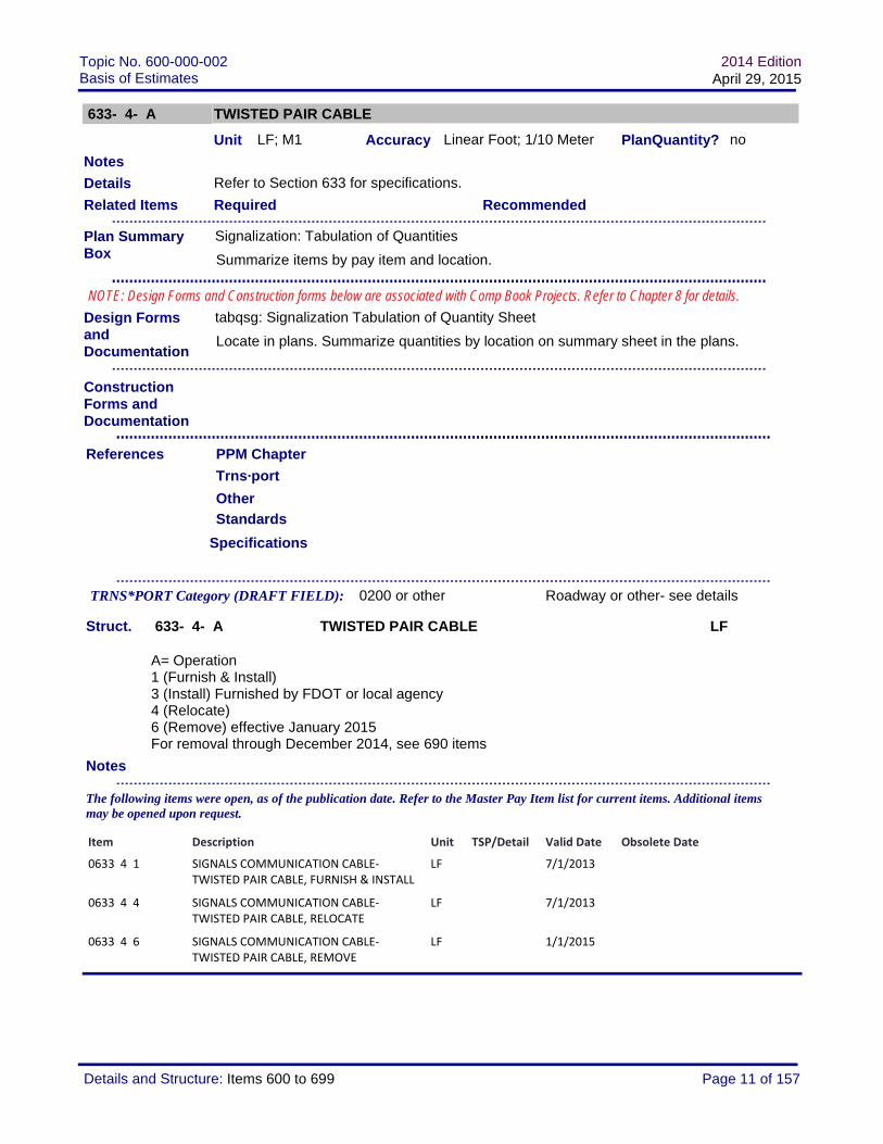
Standards Index No. 17727
Specifications Section 634
http://www.dot.state.fl.us/specificationsoffice/Implemented/SpecBooks
Struct. 634- 4-ABC SPAN WIRE ASSEMBLY PI
A = Operation1 (Furnish & Install)3 (Install) Furnished by FDOT or local agency4 (Adjust) BC=005 (Replace) BC=00 for maintenance activities6 (Remove, poles to remain) BC=00 effective January 2015Remove: Use item 690-80 through December 20147 (Re-tension Cable) BC=00 for maintenance activities
B= Attachment Type 4 (Single Point) 5 (Two Point)
C = Type Span1 (Perpendicular)2 (Diagonal) see details above; flashing beacon installations only3 (Box or Drop Box)4 (Other - As Shown In Plans) Details required for approved design variances
Notes
TRNS*PORT Category (DRAFT FIELD): 0500 Signalization (or ITS)
The following items were open, as of the publication date. Refer to the Master Pay Item list for current items. Additional items may be opened upon request.
Item Description Unit TSP/Detail Valid Date Obsolete Date
0634 4141 SPAN WIRE ASSEMBLY, F&I, SINGLE POINT, PERPENDICULAR
PI 1/1/2013
0634 4142 SPAN WIRE ASSEMBLY, F&I, SINGLE POINT, DIAGONAL
PI 1/1/2013
0634 4143 SPAN WIRE ASSEMBLY, F&I, SINGLE POINT, BOX OR DROP BOX
PI 1/1/2013
0634 4144 SPAN WIRE ASSEMBLY, F&I, SINGLE POINT, OTHER TYPE
PI A 1/1/2013
0634 4151 SPAN WIRE ASSEMBLY, F&I, TWO POINT, PERPENDICULAR
PI 1/1/2013
0634 4152 SPAN WIRE ASSEMBLY, F&I, TWO POINT, DIAGONAL
PI 1/1/2013
0634 4153 SPAN WIRE ASSEMBLY, F&I, TWO POINT, BOX
PI 1/1/2013
0634 4154 SPAN WIRE ASSEMBLY, F&I, TWO POINT, OTHER TYPE
PI A 1/1/2013
0634 4341 SPAN WIRE ASSEMBLY, INSTALL, SINGLE POINT ATTACH, PERPENDICULAR
PI 1/1/2013
0634 4342 SPAN WIRE ASSEMBLY, INSTALL, SINGLE POINT ATTACH, DIAGONAL
PI 1/1/2013
Page 15 of 157Details and Structure: Items 600 to 699
Topic No. 600-000-002Basis of Estimates
2014 EditionApril 29, 2015
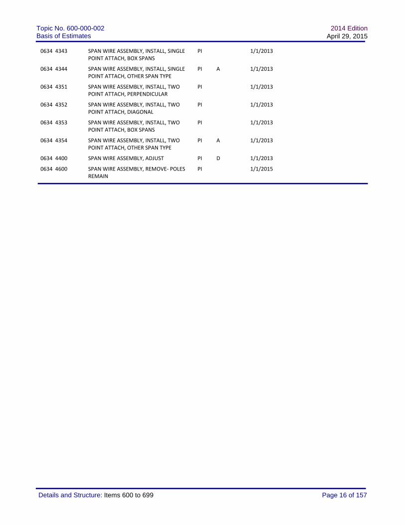
0634 4343 SPAN WIRE ASSEMBLY, INSTALL, SINGLE POINT ATTACH, BOX SPANS
PI 1/1/2013
0634 4344 SPAN WIRE ASSEMBLY, INSTALL, SINGLE POINT ATTACH, OTHER SPAN TYPE
PI A 1/1/2013
0634 4351 SPAN WIRE ASSEMBLY, INSTALL, TWO POINT ATTACH, PERPENDICULAR
PI 1/1/2013
0634 4352 SPAN WIRE ASSEMBLY, INSTALL, TWO POINT ATTACH, DIAGONAL
PI 1/1/2013
0634 4353 SPAN WIRE ASSEMBLY, INSTALL, TWO POINT ATTACH, BOX SPANS
PI 1/1/2013
0634 4354 SPAN WIRE ASSEMBLY, INSTALL, TWO POINT ATTACH, OTHER SPAN TYPE
PI A 1/1/2013
0634 4400 SPAN WIRE ASSEMBLY, ADJUST PI D 1/1/2013
0634 4600 SPAN WIRE ASSEMBLY, REMOVE‐ POLES REMAIN
PI 1/1/2015
Page 16 of 157Details and Structure: Items 600 to 699

Topic No. 600-000-002Basis of Estimates
2014 EditionApril 29, 2015
634- 5- A FIBERGLASS INSULATOR
Unit LF; M1 Accuracy Linear Foot; 1/10 Meter PlanQuantity? no
This pay item is for traffic control devices, including traffic signals and ITS devices.
Fiberglass Insulators are to be used on span wires located within 6 feet of overhead electric power lines. Detail length of each insulator in the plans.
Required Recommended
Standards
Specifications Section 634
Normally requires SHOP DRAWINGS
Struct. 634- 5- A FIBERGLASS INSULATOR LF
A = Operation1 (Furnish & Install)
Notes
T: Plan Details and/or Technical Specifications required
Details
Record final quantity on the tabulation sheet (plans) or computation form (comp book).
Related Items
Design Forms and Documentation
PPM Chapter
Notes
References
tabqsg: Signalization Tabulation of Quantity Sheet
Locate in plans. Summarize quantities by location on summary sheet in the plans.
No additional form required; use plans summary or comp book
Trns·port
TRNS*PORT Category (DRAFT FIELD): 0500 Signalization (or ITS)
The following items were open, as of the publication date. Refer to the Master Pay Item list for current items. Additional items may be opened upon request.
Other
Construction Forms and Documentation
Plan Summary Box
Signalization: Tabulation of Quantities
Summarize items by pay item and location.
NOTE: Design Forms and Construction forms below are associated with Comp Book Projects. Refer to Chapter 8 for details.
Item Description Unit TSP/Detail Valid Date Obsolete Date
0634 5 1 FIBERGLASS INSULATOR, FURNISH & INSTALL
LF 1/1/2013
Page 17 of 157Details and Structure: Items 600 to 699

Topic No. 600-000-002Basis of Estimates
2014 EditionApril 29, 2015
634- 6- A MESSENGER WIRE- Maintenance Use Only
Unit LF; M1 Accuracy Linear Foot; 1/10 Meter PlanQuantity? no
MAINTENANCE CONTRACTS ONLY
For new installations, the messenger wire is included with the Span Wire Assembly.
For Repair/Replacement, do not include separate pay when entire Span Wire Assembly is replaced.
Required Recommended
Standards Index No. 17356, 17727
Specifications
Normally requires SHOP DRAWINGS
Struct. 634- 6- A MESSENGER WIRE- Maintenance Use Only LF
A = Operation1 (Furnish & Install) Maintenance/replacement use only
Notes
T: Plan Details and/or Technical Specifications required
Details
Record final quantity on the tabulation sheet (plans) or computation form (comp book).
Related Items
Design Forms and Documentation
PPM Chapter
Notes
References
tabqsg: Signalization Tabulation of Quantity Sheet
Locate in plans. Summarize quantities by location on summary sheet in the plans.
No additional form required; use plans summary or comp book
Trns·port
TRNS*PORT Category (DRAFT FIELD): 0500 Signalization (or ITS)
The following items were open, as of the publication date. Refer to the Master Pay Item list for current items. Additional items may be opened upon request.
Other
Construction Forms and Documentation
Plan Summary Box
Signalization: Tabulation of Quantities
Summarize items by pay item and location.
NOTE: Design Forms and Construction forms below are associated with Comp Book Projects. Refer to Chapter 8 for details.
Item Description Unit TSP/Detail Valid Date Obsolete Date
0634 6 1 MESSENGER WIRE, FURNISH & INSTALL‐ REPLACE EXISTING
LF T 1/1/2013
Page 18 of 157Details and Structure: Items 600 to 699

Topic No. 600-000-002Basis of Estimates
2014 EditionApril 29, 2015
634-Maint SPAN WIRE ASSEMBLY- Maintenance Use only
Unit LF; M1 Accuracy Linear Foot; 1/10 Meter PlanQuantity? ?
Maintenance Item: Not Valid for Construction Contracts
MAINTENANCE CONTRACTS ONLYAdditional BOE details pending
Required Recommended
Standards
Specifications
Struct. 634-Maint SPAN WIRE ASSEMBLY- Maintenance Use only LF
Notes
Details
Related Items
Design Forms and Documentation
PPM Chapter
Notes
References
Trns·port
TRNS*PORT Category (DRAFT FIELD):
The following items were open, as of the publication date. Refer to the Master Pay Item list for current items. Additional items may be opened upon request.
Other
Construction Forms and Documentation
Plan Summary Box
Maintenance Item- No Form Required
NA
NOTE: Design Forms and Construction forms below are associated with Comp Book Projects. Refer to Chapter 8 for details.
Page 19 of 157Details and Structure: Items 600 to 699

Topic No. 600-000-002Basis of Estimates
2014 EditionApril 29, 2015
635- 2- AB PULL & SPLICE BOX
Unit EA Accuracy Each PlanQuantity? no
Jan 2015: See updated guidance for plan summary boxes
Use in accordance with Section 635 of the specifications.
DIMENSIONS: For signals applications, the spec calls for size B=1. For fiber optic cable applications, the spec calls for size B=2. When a different size is needed, it should be noted in the plans.*************************INSTALL (A=3): Item furnished by maintaining agency. Plan details required to inform contractor how to obtain pull & junction box. Include Agency name, contact name & number, storage location, and/or delivery instructions (agency delivery or contractor pick-up).
RELOCATE (A=4): Depending on the type of box, current condition, and the extent of the relocation, replacement versus relocation should be considered. When a box is to be relocated, specs or plan details should include the removal, protection/relocation, and reinstallation- in accordance with the specs & standards.
REMOVE: Removal is normally included with clearing and grubbing. When replacing existing pull & splice box without clearing and grubbing, include the removal in the cost of the new box.
*************************PLAN SUMMARY FORMS: Tabulate the pay item on the appropriate Signals or Lighting tabulation sheet(s).Summary of General Items summary box may be used for sidewalk repairs only when component plans for signals or lighting do not exist.
TRNSPORT: Load this pay item into the applicable category. For signals applications, load in the signals category; for lighting applications, load in the lighting category; similarly for other applications.
Required Recommended
Standards
Specifications
Details
Related Items
Design Forms and Documentation
PPM Chapter
Notes
References
COMP 700-050-03: Linear Measurement, Component Weight, Per Hour, Per Day or Per Each Computation and Continuation
Locate in the plans. Summarize quantities by location in the computation book.
Trns·port
Other
Construction Forms and Documentation
Plan Summary Box
Multiple: Multiple forms may be applicable. See details above.
Refer to BOE details for project application.
NOTE: Design Forms and Construction forms below are associated with Comp Book Projects. Refer to Chapter 8 for details.
Page 20 of 157Details and Structure: Items 600 to 699

Topic No. 600-000-002Basis of Estimates
2014 EditionApril 29, 2015
Struct. 635- 2- AB PULL & SPLICE BOX EA
A= Operation1 (Furnish & Install)3 (Install) B=0; item furnished by FDOT or local agency4 (Relocate) B=0; see detail5 (Repair) maintenance use only
B= Cover Size; minimum dimensions, per specification1 (13 x 24) 2 (24 x 36) large size3 (30” X 60”rectangular or 36” round) splice vault
Notes
TRNS*PORT Category (DRAFT FIELD):
The following items were open, as of the publication date. Refer to the Master Pay Item list for current items. Additional items may be opened upon request.
Item Description Unit TSP/Detail Valid Date Obsolete Date
0635 2 11 PULL & SPLICE BOX, F&I, 13" x 24" COVER SIZE
EA 7/1/2013
0635 2 12 PULL & SPLICE BOX, F&I, 24" X 36" COVER SIZE
EA 7/1/2013
0635 2 13 PULL & SPLICE BOX, F&I, 30" X 60" RECTANGULAR OR 36" ROUND COVER SIZE
EA 7/1/2013
0635 2 30 PULL & SPLICE BOX, INSTALL EA 7/1/2013
0635 2 40 PULL & SPLICE BOX, RELOCATE EA 7/1/2013
0635 2 50 PULL & SPLICE BOX, REPAIR EA M 7/1/2013
Page 21 of 157Details and Structure: Items 600 to 699

Topic No. 600-000-002Basis of Estimates
2014 EditionApril 29, 2015
635- 3- AB JUNCTION BOX
Unit EA Accuracy Each PlanQuantity? no
Jan 2015: See updated guidance for plan summary boxes
Use in accordance with Section 635 of the specifications.
INSTALL (A=3): Item furnished by maintaining agency. Plan details required to inform contractor how to obtain pull & junction box. Include Agency name, contact name & number, storage location, and/or delivery instructions (agency delivery or contractor pick-up).
RELOCATE (A=4): Depending on the type of box, current condition, and the extent of the relocation, replacement versus relocation should be considered. When a box is to be relocated, specs or plan details should include the removal, protection/relocation, and reinstallation- in accordance with the specs & standards.
REMOVE: Removal is normally included with clearing and grubbing. When replacing existing box without clearing and grubbing, include the removal in the cost of the new box.
********************PLAN SUMMARY FORMS: Tabulate the pay item on the appropriate Signals or Lighting tabulation sheet(s).Summary of General Items summary box may be used for sidewalk repairs only when component plans for signals or lighting do not exist.
Required Recommended
Standards
Specifications
Struct. 635- 3- AB JUNCTION BOX EA
A= Operation1 (Furnish & Install)3 (Install) B=0; item furnished by FDOT or local agency4 (Relocate) B=0; see detail
Details
Related Items
Design Forms and Documentation
PPM Chapter
Notes
References
COMP 700-050-03: Linear Measurement, Component Weight, Per Hour, Per Day or Per Each Computation and Continuation
Locate in the plans. Summarize quantities by location in the computation book.
Trns·port
TRNS*PORT Category (DRAFT FIELD):
Other
Construction Forms and Documentation
Plan Summary Box
Multiple: Multiple forms may be applicable. See details above.
Refer to BOE details for project application.
NOTE: Design Forms and Construction forms below are associated with Comp Book Projects. Refer to Chapter 8 for details.
Page 22 of 157Details and Structure: Items 600 to 699

Topic No. 600-000-002Basis of Estimates
2014 EditionApril 29, 2015
B= Type1 (Aerial)2 (Mounted)*3 (Embedded)**May be incidental for some applications
Notes
The following items were open, as of the publication date. Refer to the Master Pay Item list for current items. Additional items may be opened upon request.
Item Description Unit TSP/Detail Valid Date Obsolete Date
0635 3 11 JUNCTION BOX, FURNISH & INSTALL, AERIAL
EA 7/1/2013
0635 3 12 JUNCTION BOX, FURNISH & INSTALL, MOUNTED
EA 7/1/2013
0635 3 40 JUNCTION BOX, RELOCATE EA 7/1/2013
Page 23 of 157Details and Structure: Items 600 to 699

Topic No. 600-000-002Basis of Estimates
2014 EditionApril 29, 2015
639- 1-ABC ELECTRICAL POWER SERVICE
Unit AS Accuracy Assembly PlanQuantity? no
This pay item is for signals, lighting, ITS, and other roadway applications.
Grounding, per index 17736 and Section 620, is incidental to power service.
Required Recommended
Standards
Specifications
Struct. 639- 1-ABC ELECTRICAL POWER SERVICE AS
A= Operation1 (Furnish & Install)4 (Relocate) C=06 (Remove) C=0
B= Type of Service1 (Overhead)2 (Underground)
C= Meter Base1 (Furnished By Power Company)2 (Purchased By Contractor From Power Company)3 (Not Required)
Notes
Details
Related Items
Design Forms and Documentation
PPM Chapter
Notes
References
COMP 700-050-03: Linear Measurement, Component Weight, Per Hour, Per Day or Per Each Computation and Continuation
Locate in the plans. Summarize quantities by location in the computation book.
Trns·port
TRNS*PORT Category (DRAFT FIELD): Multiple Roadway, Signals, Lighting, etc
The following items were open, as of the publication date. Refer to the Master Pay Item list for current items. Additional items may be opened upon request.
Other
Construction Forms and Documentation
Plan Summary Box
Signalization: Tabulation of Quantities
Summarize items by pay item and location.
NOTE: Design Forms and Construction forms below are associated with Comp Book Projects. Refer to Chapter 8 for details.
Page 24 of 157Details and Structure: Items 600 to 699

Topic No. 600-000-002Basis of Estimates
2014 EditionApril 29, 2015
Item Description Unit TSP/Detail Valid Date Obsolete Date
0639 1 90 SOLAR POWER SOURCE, PROJECT 220442‐4‐
AS 1/1/2015 6/30/2015
0639 1111 ELECTRICAL POWER SERVICE, F&I, OVERHEAD, METER FURNISHED BY POWER COMPANY
AS 1/1/2013
0639 1112 ELECTRICAL POWER SERVICE, F&I, OVERHEAD METER PURCHED BY CONTRACTOR FROM POWER COMPANY
AS 1/1/2013
0639 1113 ELECTRICAL POWER SERVICE, F&I, OVERHEAD METER NOT REQUIRED
AS 1/1/2013
0639 1121 ELECTRICAL POWER SERVICE, F&I, UNDERGROUND, METER FURNISHED BY POWER COMPANY
AS 1/1/2013
0639 1122 ELECTRICAL POWER SERVICE, F&I, UNDERGROUND, METER PURCHASED BY CONTRACTOR
AS 1/1/2013
0639 1123 ELECTRICAL POWER SERVICE, F&I, UNDERGROUND, METER NOT REQUIRED
AS 1/1/2013
0639 1410 ELECTRICAL POWER SERVICE, REL OVERHEAD
AS 1/1/2013
0639 1420 ELECTRICAL POWER SERVICE, RELOCATE, UNDERGROUND
AS 1/1/2013
0639 1610 ELECTRICAL POWER SERVICE, REMOVE OVERHEAD
AS 1/1/2013
0639 1620 ELECTRICAL POWER SERVICE, REMOVE UNDERGROUND
AS 1/1/2013
Page 25 of 157Details and Structure: Items 600 to 699

Topic No. 600-000-002Basis of Estimates
2014 EditionApril 29, 2015
639- 2- A ELECTRICAL SERVICE WIRE
Unit LF; M1 Accuracy Linear Foot; 1/10 Meter PlanQuantity? no
This pay item is for signals, lighting, ITS, and other roadway applications.
MEASUREMENT (Effective January 2013): Payment is per length of complete wire run (all conductors included), not per each conductor.MEASUREMENT (Through December 2012) Verify with contract documents- plans and specs. Payment may be based on wire, or the linear foot (meter) of a single conductor.
Required Recommended
Standards
Specifications Section 639
http://www.dot.state.fl.us/specificationsoffice/Implemented/SpecBooks
Struct. 639- 2- A ELECTRICAL SERVICE WIRE LF
A = Operation1 (Furnish & Install)4 (Relocate)6 (Remove) for electrical service ONLY
Notes
Details
Record final quantity on the tabulation sheet (plans) or computation form (comp book).
Related Items
Design Forms and Documentation
PPM Chapter
Notes
References
tabqsg: Signalization Tabulation of Quantity Sheet
Locate in plans. Summarize quantities by location on summary sheet in the plans.
No additional form required; use plans summary or comp book
Trns·port
TRNS*PORT Category (DRAFT FIELD): 0500 Signalization (or ITS)
The following items were open, as of the publication date. Refer to the Master Pay Item list for current items. Additional items may be opened upon request.
Other
Construction Forms and Documentation
Plan Summary Box
Signalization: Tabulation of Quantities
Summarize items by pay item and location.
NOTE: Design Forms and Construction forms below are associated with Comp Book Projects. Refer to Chapter 8 for details.
Item Description Unit TSP/Detail Valid Date Obsolete Date
0639 2 1 ELECTRICAL SERVICE WIRE LF 1/1/2013
0639 2 4 ELECTRICAL SERVICE WIRE, RELOCATE LF 1/1/2013
0639 2 6 ELECTRICAL SERVICE WIRE, REMOVE LF 1/1/2015
Page 26 of 157Details and Structure: Items 600 to 699

Topic No. 600-000-002Basis of Estimates
2014 EditionApril 29, 2015
639- 3- AB ELECTRICAL SERVICE DISCONNECT
Unit EA Accuracy Each PlanQuantity? no
This pay item is for signals, lighting, ITS, and other roadway applications.
Required Recommended
Standards Index No. 17736
Specifications Section 639
Normally requires SHOP DRAWINGS
http://www.dot.state.fl.us/specificationsoffice/Implemented/SpecBooks
Struct. 639- 3- AB ELECTRICAL SERVICE DISCONNECT EA
A = Operation1 (Furnish & Install)6 (Remove)
B = Type Mount1 (Pole)2 (Cabinet)
Notes
Details
Record final quantity on the tabulation sheet (plans) or computation form (comp book).
Related Items
Design Forms and Documentation
PPM Chapter
Notes
References
tabqsg: Signalization Tabulation of Quantity Sheet
Locate in plans. Summarize quantities by location on summary sheet in the plans.
No additional form required; use plans summary or comp book
Trns·port
TRNS*PORT Category (DRAFT FIELD): 0500 Signalization (or ITS)
The following items were open, as of the publication date. Refer to the Master Pay Item list for current items. Additional items may be opened upon request.
Other
Construction Forms and Documentation
Plan Summary Box
Signalization: Tabulation of Quantities
Summarize items by pay item and location.
NOTE: Design Forms and Construction forms below are associated with Comp Book Projects. Refer to Chapter 8 for details.
Item Description Unit TSP/Detail Valid Date Obsolete Date
0639 3 11 ELECTRICAL SERVICE DISCONNECT, F&I, POLE MOUNT
EA 1/1/2013
0639 3 12 ELECTRICAL SERVICE DISCONNECT, F&I, CABINET
EA 1/1/2013
0639 3 60 ELECTRICAL SERVICE DISCONNECT, REMOVE
EA 1/1/2013
Page 27 of 157Details and Structure: Items 600 to 699

Topic No. 600-000-002Basis of Estimates
2014 EditionApril 29, 2015
639- 4- A SIGNALS- EMERGENCY GENERATOR (PORTABLE)
Unit Mixed Accuracy Refer to item structure and details
PlanQuantity? no
Selected items are for Emergency / Pre-Event contract use only.
This pay item is for traffic control devices, including traffic signals and ITS devices, subject to the additional guidance below for emergency/pre-event contracts.
Emergency Generators are not to be permanantly installed for signalized intersections. For critical intersections, use a UPS. In the event of an extended outage, UPS will serve the intersection until the District implements emergency procedures. Contact the State Traffic Operations Office for additional guidance.
FURNISH & INSTALL: COORDINATE THE USE OF THIS ITEM WITH THE STATE TRAFFIC OPERATIONS OFFICE. Tech Spec needs to address several issues related to the generator: Size, capacity, mounting, maintenance, and security. *** Generators cannot be furnished to the maintenance yard or maintaining agency using construction funds.*** If Generator is approved to be installed at the signals location, maintenance agreements should be completed with maintaining agency. Installation details should address securing generator to minimize potential theft.
INSTALL: For Pre-Event or Emergency contracts, coordinate the use of this item with the District Maintenance Office, to ensure the availability of generators. Tech Spec should detail security of generator and instructions for returning unit to FDOT maintenance yard.
Retrofit: Signalized location has been retrofit to accept generator connection.
Not Retrofit: Signalized location has NOT been retrofit to accept generator connection; contractor must complete the retrofit prior to generator installation. Payment for retrofit operation is included in the payment for installing generator.
Monitor & Refuel: Tech Specs should detail monitoring requirements. Fuel to be included in payment for hourly rate. (No separate payment for fuel.)
Install Generator Housing (Item furnished by maintaining agency): Details or Tech Spec should indicate that the contractor is to coordinate with the maintaining agency for pick-up/delivery of the housing to the project site. Contractor will install housing. Details or specs should indicate approximate housing dimensions, and whether a foundation/pad (included in this item for payment) is necessary.
Required Recommended
Details
Record final quantity on the tabulation sheet (plans) or computation form (comp book).
Related Items
Design Forms and Documentation
PPM Chapter
Notes
References
tabqsg: Signalization Tabulation of Quantity Sheet
Locate in plans. Summarize quantities by location on summary sheet in the plans.
No additional form required; use plans summary or comp bookConstruction Forms and Documentation
Plan Summary Box
Signalization: Tabulation of Quantities
Summarize items by pay item and location.
NOTE: Design Forms and Construction forms below are associated with Comp Book Projects. Refer to Chapter 8 for details.
Page 28 of 157Details and Structure: Items 600 to 699

Topic No. 600-000-002Basis of Estimates
2014 EditionApril 29, 2015
Standards Index 17841
Specifications Min Specs A678
Struct. 639- 4- A SIGNALS- EMERGENCY GENERATOR (PORTABLE) Mixed
A = Operation1 (Furnish & Install) Blocked 8-10-083 (Install - Retrofit; FDOT furnished) EA; For Emergency /Pre-Event contracts only. Signalized location HAS BEEN RETROFIT to accept generator connection.4 (Install - Not Retrofit; FDOT furnished) EA; For Emergency /Pre-Event contracts only. Signalized location HAS NOT BEEN RETROFIT to accept generator connection.5 (Monitor and Refuel) HR; For Emergency /Pre-Event contracts only6 (Install Generator Housing only) EA; housing furnished by maintaining agency.
Notes
T: Plan Details and/or Technical Specifications required
Trns·port
TRNS*PORT Category (DRAFT FIELD): 0500 Signalization (or ITS)
The following items were open, as of the publication date. Refer to the Master Pay Item list for current items. Additional items may be opened upon request.
Other
Item Description Unit TSP/Detail Valid Date Obsolete Date
0639 4 3 EMERGENCY GENERATOR ‐ PORTABLE INSTALL‐ RETROFIT; FDOT FURNISHED
EA T 1/1/2013
0639 4 4 EMERGENCY GENERATOR ‐ PORTABLE, INSTALL‐ NOT RETROFIT, FDOT FURNISHED
EA T 1/1/2013
0639 4 5 EMERGENCY GENERATOR ‐ PORTABLE, MONITOR & REFUEL
HR T 1/1/2013
0639 4 6 EMERGENCY GENERATOR ‐ PORTABLE, INSTALL HOUSING ONLY
EA T 1/1/2013
Page 29 of 157Details and Structure: Items 600 to 699

Topic No. 600-000-002Basis of Estimates
2014 EditionApril 29, 2015
639- 5- A EMERGENCY GENERATOR- PERMANENT
Unit EA Accuracy Each PlanQuantity? no
Intended for Maintenance Contracts Only.
Refer to E639- items for additional items.
Emergency Generators are not to be used for signalized intersections. For critical intersections, use a UPS. In the event of an extended outage, UPS will serve the intersection until the District implements emergency procedures. Contact the State Traffic Operations Office for additional guidance.
Required Recommended
Standards
Specifications
Struct. 639- 5- A EMERGENCY GENERATOR- PERMANENT EA
A= Generator Size1 (up to 25 KW)2 (25-50 KW)
Notes
Details
Related Items
Design Forms and Documentation
PPM Chapter
Notes
References
tabqsg: Signalization Tabulation of Quantity Sheet
Locate in plans. Summarize quantities by location on summary sheet in the plans.
No additional form required; use plans summary or comp book
Trns·port
TRNS*PORT Category (DRAFT FIELD): 0500 Signalization (or ITS)
The following items were open, as of the publication date. Refer to the Master Pay Item list for current items. Additional items may be opened upon request.
Other
Construction Forms and Documentation
Plan Summary Box
Signalization: Tabulation of Quantities
Summarize items by pay item and location.
NOTE: Design Forms and Construction forms below are associated with Comp Book Projects. Refer to Chapter 8 for details.
Item Description Unit TSP/Detail Valid Date Obsolete Date
0639 5 1 EMERGENCY GENERATOR‐PERMANENT, UP TO 25 KW
EA T 1/1/2013 6/30/2015
0639 5 2 EMERGENCY GENERATOR‐PERMANENT 26‐50 KW
EA T 1/1/2013 6/30/2015
Page 30 of 157Details and Structure: Items 600 to 699

Topic No. 600-000-002Basis of Estimates
2014 EditionApril 29, 2015
639- 6- A ELECTRICAL POWER SERVICE TRANSFORMER
Unit EA Accuracy Each PlanQuantity?
Intended for transformers required with Electrical Power Service. Complete specifications/details are required in the contract documents.
Required Recommended
Standards
Specifications
Struct. 639- 6- A ELECTRICAL POWER SERVICE TRANSFORMER EA
A= Operation1 (Furnish & Install)2 (Replace)
Notes
T: Plan Details and/or Technical Specifications required
Details
Related Items
Design Forms and Documentation
PPM Chapter
Notes
References
Trns·port
TRNS*PORT Category (DRAFT FIELD):
The following items were open, as of the publication date. Refer to the Master Pay Item list for current items. Additional items may be opened upon request.
Other
Construction Forms and Documentation
Plan Summary Box
Multiple: Multiple forms may be applicable. See details above.
Refer to BOE details for project application.
NOTE: Design Forms and Construction forms below are associated with Comp Book Projects. Refer to Chapter 8 for details.
Item Description Unit TSP/Detail Valid Date Obsolete Date
0639 6 1 ELECTRICAL POWER SERVICE‐ TRANSFORMER FURNISH & INSTALL
EA T 1/1/2014
Page 31 of 157Details and Structure: Items 600 to 699

Topic No. 600-000-002Basis of Estimates
2014 EditionApril 29, 2015
639- 10- ELECTRICAL POWER SERVICE DIAGNOSTIC AND MISCELLANEOUS REPAIR
Unit EA Accuracy Each PlanQuantity? no
Intended for Maintenance Contracts Only.
Required Recommended
Standards
Specifications
Struct. 639- 10- ELECTRICAL POWER SERVICE DIAGNOSTIC AND MISCELLANEOUS REPAIR
EA
Notes
Details
Related Items
Design Forms and Documentation
PPM Chapter
Notes
References
COMP 700-050-03: Linear Measurement, Component Weight, Per Hour, Per Day or Per Each Computation and Continuation
Locate in the plans. Summarize quantities by location in the computation book.
Trns·port
TRNS*PORT Category (DRAFT FIELD):
The following items were open, as of the publication date. Refer to the Master Pay Item list for current items. Additional items may be opened upon request.
Other
Construction Forms and Documentation
Plan Summary Box
Signalization: Tabulation of Quantities
Summarize items by pay item and location.
NOTE: Design Forms and Construction forms below are associated with Comp Book Projects. Refer to Chapter 8 for details.
Item Description Unit TSP/Detail Valid Date Obsolete Date
0639 10 ELECTRICAL POWER SERVICE DIAGNOSTIC AND MISCELLANEOUS REPAIR
EA 1/1/2013
Page 32 of 157Details and Structure: Items 600 to 699

Topic No. 600-000-002Basis of Estimates
2014 EditionApril 29, 2015
639-Maint EMERGENCY GENERATOR & ELECTRICAL POWER SERVICEMaintenance Contracts Only
Unit Mixed Accuracy Refer to item structure and details
PlanQuantity? ?
Maintenance Item: Not Valid for Construction Contracts
MAINTENANCE CONTRACTS ONLYAdditional BOE details pending
Required Recommended
Standards
Specifications
Struct. 639-Maint EMERGENCY GENERATOR & ELECTRICAL POWER SERVICEMaintenance Contracts Only
Mixed
Notes
Details
Related Items
Design Forms and Documentation
PPM Chapter
Notes
References
Trns·port
TRNS*PORT Category (DRAFT FIELD):
The following items were open, as of the publication date. Refer to the Master Pay Item list for current items. Additional items may be opened upon request.
Other
Construction Forms and Documentation
Plan Summary Box
Maintenance Item- No Form Required
NA
NOTE: Design Forms and Construction forms below are associated with Comp Book Projects. Refer to Chapter 8 for details.
Item Description Unit TSP/Detail Valid Date Obsolete Date
E639 4 2 EMERGENCY GENERATOR INSTALLATION ‐ RETROFIT CABINET (TRANSPORT, INSTALL, MAINTAIN AND RETURN)
EA 1/1/2013
E639 4 3 EMERGENCY GENERATOR INSTALLATION ‐ NOT RETROFITTED (TRANSPORT, INSTALL, MAINTAIN AND RETURN)
EA 1/1/2013
E639 5 EMERGENCY GENERATOR MONITORING & RE‐FUELING INC ALL INCIDENTALS REQUIRED FOR OPERATING GENERATOR
HR 1/1/2013
Page 33 of 157Details and Structure: Items 600 to 699

Topic No. 600-000-002Basis of Estimates
2014 EditionApril 29, 2015
641- 1- STRAIN POLES, GUYING, CONCRETE Maintenance Use Only
Unit EA Accuracy Each PlanQuantity? no
Valid through 12-31-13. Payment for span wire installation is included with F&I of span wire assembly. See separate items for F&I payment.
Per the specification, "to be used for service pole applications, luminaire support, and strain poles for span wire support of traffic signals, signs, and other devices."
Required Recommended
Standards Index No. 17725
Specifications Section 641
http://www.dot.state.fl.us/specificationsoffice/Implemented/SpecBooks
Struct. 641- 1- STRAIN POLES, GUYING, CONCRETE Maintenance Use Only
EA
Notes
Details
Record final quantity on the tabulation sheet (plans) or computation form (comp book).
Related Items
Design Forms and Documentation
PPM Chapter
Notes
References
tabqsg: Signalization Tabulation of Quantity Sheet
Locate in plans. Summarize quantities by location on summary sheet in the plans.
No additional form required; use plans summary or comp book
Trns·port
TRNS*PORT Category (DRAFT FIELD): 0500 Signalization (or ITS)
The following items were open, as of the publication date. Refer to the Master Pay Item list for current items. Additional items may be opened upon request.
Other
Construction Forms and Documentation
Plan Summary Box
Signalization: Tabulation of Quantities
Summarize items by pay item and location.
NOTE: Design Forms and Construction forms below are associated with Comp Book Projects. Refer to Chapter 8 for details.
Page 34 of 157Details and Structure: Items 600 to 699

Topic No. 600-000-002Basis of Estimates
2014 EditionApril 29, 2015
641- 2- AB PRESTRESSED CONCRETE POLE (Index 17725)
Unit EA Accuracy Each PlanQuantity? no
Effective January 2015, remove items moved from 690s.
This pay item is for traffic control devices, including traffic signals and ITS devices.Pole description, including the type, height, and other details must be included in the signal plans.This item is used as detailed on index 17725 and Index 17764 (pedestrian pedestal).
Poles must be on the QPL.
REMOVE: Includes the removal of pole, foundation, and any attachments (Vehicular Signal, Pedestrian Signal, Pedestrian Detector, span wire, or other). No separate payment for removal of attachments when removed with the pole. Items become the property of the contractor, unless otherwise indicated in the contract documents.Shallow pole removal= depth of 4 feetDeep pole removal= complete removal
B=9 (Custom Design): For use ONLY when design standard index does NOT apply. Designer must show complete dimensions for pole. Supporting calculations must be completed for intended signals application. Review specification requirements to determine if notes or modified specs are needed.
Required Recommended
Standards Index No. 17725, 17764
Specifications Section 641
http://www.dot.state.fl.us/specificationsoffice/Implemented/SpecBooks
Struct. 641- 2- AB PRESTRESSED CONCRETE POLE (Index 17725) EA
A= Operation1 (Furnish & Install)3 (Install) B=06 (Complete/Deep Removal- Pedestal/Service Pole) B=0, effective January 20157 (Shallow Removal- Poles 30' and greater) B=0, effective January 2015
Details
Record final quantity on the tabulation sheet (plans) or computation form (comp book).
Related Items
Design Forms and Documentation
PPM Chapter
Notes
References
SBStrainPoles: Summary of Strain Poles, orSHStrainPole: Strain Pole Schedule
Locate in plans. Summarize quantities by location on summary sheet in the plans.
No additional form required; use plans summary or comp book
Trns·port
TRNS*PORT Category (DRAFT FIELD): 0500 Signalization (or ITS)
Other
Construction Forms and Documentation
Plan Summary Box
Signalization: Tabulation of Quantities
Summarize items by pay item and location.
NOTE: Design Forms and Construction forms below are associated with Comp Book Projects. Refer to Chapter 8 for details.
Page 35 of 157Details and Structure: Items 600 to 699

Topic No. 600-000-002Basis of Estimates
2014 EditionApril 29, 2015
8 (Complete/Deep Removal- Poles 30' and greater) B=0, effective January 2015
B = Pole Type (defined in Design Standards)1 (Type P-II Pedestal)2 (Type P-II Service Pole)3 (Type P-III)4 (Type P-IV)5 (Type P-V)6 (Type P-VI)7 (Type P-VII)8 (Type P-VIII)9 (Custom Design)*
Notes *Custom Design requires Tech Spec and/or Plan Detail
The following items were open, as of the publication date. Refer to the Master Pay Item list for current items. Additional items may be opened upon request.
Item Description Unit TSP/Detail Valid Date Obsolete Date
0641 2 11 PRESTRESSED CONCRETE POLE, F&I, TYPE P‐II PEDESTAL
EA 1/1/2013
0641 2 12 PRESTRESSED CONCRETE POLE, F&I, TYPE P‐II SERVICE POLE
EA 1/1/2013
0641 2 13 PRESTRESSED CONCRETE POLE, F&I, TYPE P‐III
EA 1/1/2013
0641 2 14 PRESTRESSED CONCRETE POLE, F&I, TYPE P‐IV
EA 1/1/2013
0641 2 15 PRESTRESSED CONCRETE POLE, F&I, TYPE P‐V
EA 1/1/2013
0641 2 16 PRESTRESSED CONCRETE POLE, F&I, TYPE P‐VI
EA 1/1/2013
0641 2 17 PRESTRESSED CONCRETE POLE, F&I, TYPE P‐VII
EA 1/1/2013
0641 2 18 PRESTRESSED CONCRETE POLE, F&I, TYPE P‐VIII
EA 1/1/2013
0641 2 19 PRESTRESSED CONCRETE POLE, F&I, CUSTOM DESIGN
EA D 1/1/2013
0641 2 30 PRESTRESSED CONCRETE POLE, INSTALL EA 1/1/2013
0641 2 60 PRESTRESSED CONCRETE POLE, COMPLETE POLE REMOVAL‐ PEDESTAL/SERVICE POLE
EA 1/1/2015
0641 2 70 PRESTRESSED CONCRETE POLE, SHALLOW POLE REMOVAL‐ POLE 30' AND GREATER
EA 1/1/2015
0641 2 80 PRESTRESSED CONCRETE POLE, COMPLETE POLE REMOVAL‐ POLE 30' AND GREATER
EA 1/1/2015
Page 36 of 157Details and Structure: Items 600 to 699

Topic No. 600-000-002Basis of Estimates
2014 EditionApril 29, 2015
641- 3-ABB CONCRETE CCTV POLE (Index 18113)
Unit EA Accuracy Each PlanQuantity?
Effective January 2015. Remove items moved from 690s. CCTV poles moved from Section 785.
CCTV Poles for cameras, per Index 18113.
REMOVE: Includes the removal of pole, foundation, and any attachments (camera, lowering device, etc.) No separate payment for removal of attachments when removed with the pole. Items become the property of the contractor, unless otherwise indicated in the contract documents.Shallow pole removal= depth of 4 feetDeep pole removal= complete removal
Required Recommended
Standards
Specifications
Struct. 641- 3-ABB CONCRETE CCTV POLE (Index 18113) EA
A= Operation1 (Furnish & Install, withlowering device)2 (Furnish & Install, without lowering device)3 (Install) BB=007 (Shallow Removal) BB=00, effective January 20158 (Deep Removal) BB=00, effective January 2015
BB = Pole Height (defined in Design Standard 18113)63 (63’)69 (69’)75 (75’)80 (80’)86 (86’)
Notes
Details
Related Items
Design Forms and Documentation
PPM Chapter
Notes
References
Trns·port
TRNS*PORT Category (DRAFT FIELD): 0500 Signalization (or ITS)
Other
Construction Forms and Documentation
Plan Summary Box
Signalization: Tabulation of Quantities
Summarize items by pay item and location.
NOTE: Design Forms and Construction forms below are associated with Comp Book Projects. Refer to Chapter 8 for details.
Page 37 of 157Details and Structure: Items 600 to 699

Topic No. 600-000-002Basis of Estimates
2014 EditionApril 29, 2015
The following items were open, as of the publication date. Refer to the Master Pay Item list for current items. Additional items may be opened upon request.
Item Description Unit TSP/Detail Valid Date Obsolete Date
0641 3 70 CONCRETE CCTV POLE, SHALLOW POLE REMOVAL
EA 1/1/2015 6/30/2015
0641 3 80 CONCRETE CCTV POLE, COMPLETE POLE REMOVAL
EA 1/1/2015 6/30/2015
0641 3163 CONCRETE CCTV POLE, FURNISH & INSTALL WITH LOWERING DEVICE, 63'
EA 1/1/2015
0641 3169 CONCRETE CCTV POLE, FURNISH & INSTALL WITH LOWERING DEVICE, 69'
EA 1/1/2015
0641 3175 CONCRETE CCTV POLE, FURNISH & INSTALL WITH LOWERING DEVICE, 75'
EA 1/1/2015
0641 3180 CONCRETE CCTV POLE, FURNISH & INSTALL WITH LOWERING DEVICE, 80'
EA 1/1/2015
0641 3186 CONCRETE CCTV POLE, FURNISH & INSTALL WITH LOWERING DEVICE, 86'
EA 1/1/2015
0641 3263 CONCRETE CCTV POLE, FURNISH & INSTALL WITHOUT LOWERING DEVICE, 63'
EA 1/1/2015
0641 3269 CONCRETE CCTV POLE, FURNISH & INSTALL WITHOUT LOWERING DEVICE, 69'
EA 1/1/2015
0641 3275 CONCRETE CCTV POLE, FURNISH & INSTALL WITHOUT LOWERING DEVICE, 75'
EA 1/1/2015
0641 3286 CONCRETE CCTV POLE, FURNISH & INSTALL WITH OUT LOWERING DEVICE, 86'
EA 1/1/2015
0641 3700 CONCRETE CCTV POLE, SHALLOW POLE REMOVAL
EA 1/1/2015
0641 3800 CONCRETE CCTV POLE, COMPLETE POLE REMOVAL
EA 1/1/2015
Page 38 of 157Details and Structure: Items 600 to 699
Topic No. 600-000-002Basis of Estimates
2014 EditionApril 29, 2015
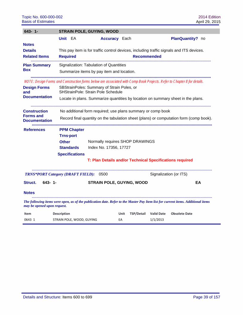
643- 1- STRAIN POLE, GUYING, WOOD
Unit EA Accuracy Each PlanQuantity? no
This pay item is for traffic control devices, including traffic signals and ITS devices.
Required Recommended
Standards Index No. 17356, 17727
Specifications
Normally requires SHOP DRAWINGS
Struct. 643- 1- STRAIN POLE, GUYING, WOOD EA
Notes
T: Plan Details and/or Technical Specifications required
Details
Record final quantity on the tabulation sheet (plans) or computation form (comp book).
Related Items
Design Forms and Documentation
PPM Chapter
Notes
References
SBStrainPoles: Summary of Strain Poles, orSHStrainPole: Strain Pole Schedule
Locate in plans. Summarize quantities by location on summary sheet in the plans.
No additional form required; use plans summary or comp book
Trns·port
TRNS*PORT Category (DRAFT FIELD): 0500 Signalization (or ITS)
The following items were open, as of the publication date. Refer to the Master Pay Item list for current items. Additional items may be opened upon request.
Other
Construction Forms and Documentation
Plan Summary Box
Signalization: Tabulation of Quantities
Summarize items by pay item and location.
NOTE: Design Forms and Construction forms below are associated with Comp Book Projects. Refer to Chapter 8 for details.
Item Description Unit TSP/Detail Valid Date Obsolete Date
0643 1 STRAIN POLE, WOOD, GUYING EA 1/1/2013
Page 39 of 157Details and Structure: Items 600 to 699

Topic No. 600-000-002Basis of Estimates
2014 EditionApril 29, 2015
643-ABB- STRAIN POLE, WOOD
Unit EA Accuracy Each PlanQuantity? no
This pay item is for traffic control devices, including traffic signals and ITS devices.
REMOVE: All wood poles are to be removed completely. Payment includes the removal of all attachments.
Required Recommended 643- 1- (2643- 1)
Standards
Specifications
Struct. 643-ABB- STRAIN POLE, WOOD EA
A = Operation1 (Furnish & Install)3 (Install) furnished by local agency4 (Relocate)6 (Remove) BB=00BB = Pole Length (Specified In 5' Increments Only)
Notes
T: Plan Details and/or Technical Specifications required
Details
Record final quantity on the tabulation sheet (plans) or computation form (comp book).
Related Items
Design Forms and Documentation
PPM Chapter
Notes
References
SBStrainPoles: Summary of Strain Poles, orSHStrainPole: Strain Pole Schedule
Locate in plans. Summarize quantities by location on summary sheet in the plans.
No additional form required; use plans summary or comp book
Trns·port
TRNS*PORT Category (DRAFT FIELD): 0500 Signalization (or ITS)
The following items were open, as of the publication date. Refer to the Master Pay Item list for current items. Additional items may be opened upon request.
Other
Construction Forms and Documentation
Plan Summary Box
Signalization: Tabulation of Quantities
Summarize items by pay item and location.
NOTE: Design Forms and Construction forms below are associated with Comp Book Projects. Refer to Chapter 8 for details.
Item Description Unit TSP/Detail Valid Date Obsolete Date
0643125 STRAIN POLE, WOOD, F&I, 25' EA 1/1/2013
0643130 STRAIN POLES, WOOD, FURNISH & INSTALL, 30'
EA 1/1/2013
0643140 STRAIN POLE, WOOD, FURNISH & INSTALL, 40'
EA 1/1/2013
Page 40 of 157Details and Structure: Items 600 to 699

Topic No. 600-000-002Basis of Estimates
2014 EditionApril 29, 2015
0643145 STRAIN POLES, WOOD, FURNISH & INSTALL, 45'
EA 1/1/2013
0643150 STRAIN POLE, WOOD, F&I, 50' EA 1/1/2013
0643155 STRAIN POLES, WOOD, FURNISH & INSTALL, 55'
EA 1/1/2013
0643600 STRAIN POLE, WOOD, REMOVE EA T 1/1/2013
Page 41 of 157Details and Structure: Items 600 to 699

Topic No. 600-000-002Basis of Estimates
2014 EditionApril 29, 2015
646- 1- AB ALUMINUM SIGNALS POLE
Unit EA Accuracy Each PlanQuantity? no
To be used in accordance with Design Standards, Index Nos. 17764 and 17784.
INSTALL: The install operation should only be used when the item is furnished by FDOT or the local agency, for installation by the contractor. Include instructions in the plans for obtaining the pole.
REMOVE: The removal of the foundation is included with the removal of the pedestal, unless otherwise noted in the plans. All attachments are included with the removal of the pole (pedestrian detector, pedestrian signal, etc.)
Required Recommended
Standards Index 17764
Specifications
Struct. 646- 1- AB ALUMINUM SIGNALS POLE EA
A= Operation1 (Furnish & Install)3 (Install) B=04 (Relocate) B=06 (Remove) B=0
B= Pole Type1 (Pedestal)2 (Pedestrian Detector Post)
Notes
Details
Related Items
Design Forms and Documentation
PPM Chapter
Notes
References
COMP 700-050-03: Linear Measurement, Component Weight, Per Hour, Per Day or Per Each Computation and Continuation
Locate in the plans. Summarize quantities by location in the computation book.
Trns·port
TRNS*PORT Category (DRAFT FIELD): 0500 Signalization (or ITS)
The following items were open, as of the publication date. Refer to the Master Pay Item list for current items. Additional items may be opened upon request.
Other
Construction Forms and Documentation
Plan Summary Box
Signalization: Tabulation of Quantities
Summarize items by pay item and location.
NOTE: Design Forms and Construction forms below are associated with Comp Book Projects. Refer to Chapter 8 for details.
Page 42 of 157Details and Structure: Items 600 to 699

Topic No. 600-000-002Basis of Estimates
2014 EditionApril 29, 2015
Item Description Unit TSP/Detail Valid Date Obsolete Date
0646 1 11 ALUMINUM SIGNALS POLE, PEDESTAL EA 1/1/2013
0646 1 12 ALUMINUM SIGNALS POLE, FURNISH & INSTALL PEDESTRIAN DETECTOR POST
EA 1/1/2013
0646 1 30 ALUMINUM SIGNALS POLE, INSTALL EA 1/1/2014
0646 1 40 ALUMINUM SIGNALS POLE, RELOCATE EA 1/1/2014
0646 1 60 ALUMINUM SIGNALS POLE, REMOVE EA 1/1/2013
Page 43 of 157Details and Structure: Items 600 to 699

Topic No. 600-000-002Basis of Estimates
2014 EditionApril 29, 2015
649- 1- AB STEEL STRAIN POLE
Unit EA Accuracy Each PlanQuantity? no
This pay item is for traffic control devices, including traffic signals and ITS devices.Pole description, including the type, height, and other details must be included in the signal plans.
PEDESTRIAN PEDESTAL: Details are provided on Index 17723 and 17764.
REMOVAL: Per the specification, includes the removal of all attachments (arms, signals, light fixtures, etc.)Shallow foundation removal= 4 foot depthDeep foundation removal= complete removal
Required Recommended
Standards Index 17723 and 17764.
Specifications
Struct. 649- 1- AB STEEL STRAIN POLE EA
A= Operation1 (Furnish & Install)3 (Install) B=06 (Remove) See B= Removal Details
B = Pole Type (defined in Design Standards)0 (Pedestal)1 (Type PS-IV)2 (Type PS - V)3 (Type PS-VI)4 (Type PS-VII)5 (Type PS - VIII)6 (Type PS-IX)
T: Selected Items may require Plan Details and/or Technical Specifications
Details
Record final quantity on the tabulation sheet (plans) or computation form (comp book).
Related Items
Design Forms and Documentation
PPM Chapter
Notes
References
SBStrainPoles: Summary of Strain Poles, orSHStrainPole: Strain Pole Schedule
Locate in plans. Summarize quantities by location on summary sheet in the plans.
No additional form required; use plans summary or comp book
Trns·port
TRNS*PORT Category (DRAFT FIELD): 0500 Signalization (or ITS)
Other
Construction Forms and Documentation
Plan Summary Box
Signalization: Tabulation of Quantities
Summarize items by pay item and location.
NOTE: Design Forms and Construction forms below are associated with Comp Book Projects. Refer to Chapter 8 for details.
Page 44 of 157Details and Structure: Items 600 to 699

Topic No. 600-000-002Basis of Estimates
2014 EditionApril 29, 2015
7 (Type PS - X)
B= Removal Details1 (Pedestal or service pole) complete removal2 (Type PS poles; foundation remains)3 (Shallow, Bolt on Attachment) 5 (Deep, Bolt on Attachment)
Notes
The following items were open, as of the publication date. Refer to the Master Pay Item list for current items. Additional items may be opened upon request.
Item Description Unit TSP/Detail Valid Date Obsolete Date
0649 1 10 STEEL STRAIN POLE, F&I, PEDESTAL EA 1/1/2013
0649 1 11 STEEL STRAIN POLE, F&I, TYPE PS‐ IV EA 1/1/2013
0649 1 12 STEEL STRAIN POLE, F&I, TYPE PS‐ V EA 1/1/2013
0649 1 13 STEEL STRAIN POLE, F&I, TYPE PS‐ VI EA 1/1/2013
0649 1 14 STEEL STRAIN POLE, F&I, TYPE PS‐ VII EA 1/1/2013
0649 1 15 STEEL STRAIN POLE, F&I, TYPE PS‐ VIII EA 1/1/2013
0649 1 16 STEEL STRAIN POLE, F&I, TYPE PS‐ IX EA 1/1/2013
0649 1 17 STEEL STRAIN POLE, F&I, TYPE PS‐ X EA 1/1/2013
0649 1 61 STEEL STRAIN POLE, REMOVE PEDESTAL OR SERVICE POLE‐ COMPLETE REMOVAL
EA 1/1/2015
0649 1 62 STEEL STRAIN POLE, REMOVE TYPE PS POLE‐ FOUNDATION REMAINS
EA 1/1/2015
0649 1 63 STEEL STRAIN POLE, REMOVE, SHALLOW FOUNDATION REMOVAL, BOLT ON ATTACHMENT
EA 1/1/2015
0649 1 65 STEEL STRAIN POLE, REMOVE, DEEP FOUNDATION REMOVAL, BOLT ON ATTACHMENT
EA 1/1/2015
Page 45 of 157Details and Structure: Items 600 to 699

Topic No. 600-000-002Basis of Estimates
2014 EditionApril 29, 2015
649- 2-ABB STEEL CCTV POLE
Unit EA Accuracy Each PlanQuantity? no
Effective January 2015 letting; replaces 785 poles for ITS applications.
To be used in accordance with Design Standards, Index No. 18113.
REMOVAL: Per the specification, includes the removal of all attachments (camera, lowering device, etc.)Shallow foundation removal= 4 foot depthDeep foundation removal= complete removal
Required Recommended
Standards
Specifications
Struct. 649- 2-ABB STEEL CCTV POLE EA
A= Operation1 (Furnish & Install, with Lowering Device)2 (Furnish & Install, without Lowering Device)3 (Install) B=06 (Remove) see remove options below
BB= Pole Height50 (50’)55 (55’)60 (60’)65 (65’)70 (70’)
BB=Remove Options01 (Pole only, entire foundation remains)03 (Shallow foundation removal, Bolt on attachment)05 (Deep/Complete foundation remval, Bolt on attachment)
Notes
Details
Related Items
Design Forms and Documentation
PPM Chapter
Notes
References
Trns·port
TRNS*PORT Category (DRAFT FIELD): 0500 Signalization (or ITS)
Other
Construction Forms and Documentation
Plan Summary Box
Signalization: Tabulation of Quantities
Summarize items by pay item and location.
NOTE: Design Forms and Construction forms below are associated with Comp Book Projects. Refer to Chapter 8 for details.
Page 46 of 157Details and Structure: Items 600 to 699

Topic No. 600-000-002Basis of Estimates
2014 EditionApril 29, 2015
The following items were open, as of the publication date. Refer to the Master Pay Item list for current items. Additional items may be opened upon request.
Item Description Unit TSP/Detail Valid Date Obsolete Date
0649 2150 STEEL CCTV POLE, FURNISH & INSTALL WITH LOWERING DEVICE, 50'
EA 1/1/2014
0649 2170 STEEL CCTV POLE, FURNISH & INSTALL WITH LOWERING DEVICE, 70'
EA 1/1/2014
0649 2250 STEEL CCTV POLE, FURNISH & INSTALL WITHOUT LOWERING DEVICE, 50'
EA 1/1/2014
0649 2255 STEEL CCTV POLE, FURNISH & INSTALL WITHOUT LOWERING DEVICE, 55'
EA 1/1/2014
0649 2260 STEEL CCTV POLE, FURNISH & INSTALL WITHOUT LOWERING DEVICE, 60'
EA 1/1/2014
0649 2265 STEEL CCTV POLE, FURNISH & INSTALL WITHOUT LOWERING DEVICE, 65'
EA 1/1/2014
0649 2270 STEEL CCTV POLE, FURNISH & INSTALL WITHOUT LOWERING DEVICE, 70'
EA 1/1/2014
0649 2601 STEEL CCTV POLE, REMOVE POLE‐ FOUNDATION REMAINS
EA 1/1/2014
0649 2603 STEEL CCTV POLE, REMOVE POLE‐ SHALLOW FOUNDATION REMOVAL, BOLT ON ATTACHMENT
EA 1/1/2014
0649 2605 STEEL CCTV POLE, REMOVE POLE‐ COMPLETE/DEEP FOUNDATION REMOVAL, BOLT ON ATTACHMENT
EA 1/1/2014
Page 47 of 157Details and Structure: Items 600 to 699

Topic No. 600-000-002Basis of Estimates
2014 EditionApril 29, 2015
649- 1A-BBB MONOTUBE ASSEMBLIES, STEEL
Unit EA Accuracy Each PlanQuantity? no
Valid through 12-31-14; call to request extended valid dates.
This pay item is for traffic control devices, including traffic signals and ITS devices.
After December 2007: Design Standards are no longer available. Please contact the State Structures Office for assistance. Ensure that the maintaining agency and local authorities have agreed to the use of a monotube. Tech Specs and/or Plan Details will be required for structural size/shape, material requirements, installation details, and measurement/payment. Foundation is to be included in the price for the complete assembly.
REMOVE: Steel poles are normally attached to a drilled shaft foundation. Payment includes the removal of all attachments (signals, signs, etc.)
For Plan Detail/Tech Spec items: The Designer should ensure that the description, materials, construction/installation requirements, method of measurement and basis of payment are available in the contract documents to clearly define the work to be completed for payment under this item.
NOT TO BE USED FOR ITS Projects. Refer to 780 items.Item used for monotube structures which carry signals. Refer to Plans Preparation Manual, Vol I Chapters 7 and 29, Vol II Chapter 24 for details.Use Monotube Tabulation Sheet (available from CADD bar menu).
Required Recommended
Standards Index No. 17746 (Index valid through 12/2007)
Specifications
Struct. 649- 1A-BBB MONOTUBE ASSEMBLIES, STEEL EA
A = Operation1 (Furnish & Install)
T: Plan Details and/or Technical Specifications required
Details
Record final quantity on the tabulation sheet (plans) or computation form (comp book).
Related Items
Design Forms and Documentation
PPM Chapter
Notes
References
SHMono Tube: Monotube Tabulation
Locate in plans. Summarize quantities by location on summary sheet in the plans.
No additional form required; use plans summary or comp book
Trns·port
TRNS*PORT Category (DRAFT FIELD): 0500 Signalization (or ITS)
Other
Construction Forms and Documentation
Plan Summary Box
Signalization: Tabulation of Quantities
Summarize items by pay item and location.
NOTE: Design Forms and Construction forms below are associated with Comp Book Projects. Refer to Chapter 8 for details.
Page 48 of 157Details and Structure: Items 600 to 699

Topic No. 600-000-002Basis of Estimates
2014 EditionApril 29, 2015
6 (Remove) see remove options below.
BBB = Size110 (110’ span)135 (135’ span)160 (160’ span)185 (185’ span)
BBB= Remove Options1 (Pole only, entire foundation remains)3 (Shallow, Bolt on attachment)5 (Deep, Bolt on attachment)
Notes
The following items were open, as of the publication date. Refer to the Master Pay Item list for current items. Additional items may be opened upon request.
Item Description Unit TSP/Detail Valid Date Obsolete Date
0649 11185 STEEL MONOTUBE ASSEMBLY, FURNISH & INSTALL, STANDARD 185' SPAN
EA T 1/1/2013 12/31/2020
Page 49 of 157Details and Structure: Items 600 to 699

Topic No. 600-000-002Basis of Estimates
2014 EditionApril 29, 2015
649- 3A-BCC STEEL MAST ARM ASSEMBLY
Unit EA Accuracy Each PlanQuantity? no
Remove operation effective January 2015; replaces 690 items.
This pay item is for traffic control devices, including traffic signals and ITS devices.
Refer to PPM (Plans Preparation Manual) Vol 1, Chapters 7 and 29 for current FDOT Policy on the use of Mast Arms: in general, only to be used within 10 miles of coastline.
Pole description, including the type, height, and other details must be included in the signal plans. Payment includes foundation, as well as all incidentals, per specifications.
When "w/ Luminaire" is used, detail luminaire requirements in the plans.
Double Arm with luminaire requires special design (CC=99); not covered by design standard index. Complete calculations are required.
BCC=999 (Custom) to be used only when wind loads, specifications and/or standards do not apply, due to significant design changes. Complete design calculations, including wind loads, are required in the plans.
Note: For minor changes in arm lengths, such as field cuts, use the standard pay item, with a note in the plans for the final length.
When street name signs are to be located on a signals mast arm, tabulate and detail the sign (size, shape, letters, etc.) in the SIGNING plans. Load the pay item in the SIGNING category. The installation location may be shown on the signal plans.
REMOVE: Detail Mast Arm Assemblies to be removed in the plans (Summary Box or Signals Tabulation Sheet). Includes the removal of the foundation, as well as any attachments (vehicular/pedestrian signals, pedestrian detector, lighting, etc.)
For Plan Detail/Tech Spec items: The Designer should ensure that the description, materials, construction/installation requirements, method of measurement and basis of payment are available in the contract documents to clearly define the work to be completed for payment under this item.
Required Recommended
Vol 1, 7.4
Details
Record final quantity on the tabulation sheet (plans) or computation form (comp book).
Related Items
Design Forms and Documentation
PPM Chapter
Notes
References
SHMastArmTab 1 or SHMAstArmTab 2: Signalization Mast Arm Tabulation, orSHSpecialMastArmDsgn or SHStandardMast ArmDsgn: Mast Arm Assembly 17745 or 17743
Locate in plans. Summarize quantities by location on summary sheet in the plans.
No additional form required; use plans summary or comp book
Trns·port
Other
Construction Forms and Documentation
Plan Summary Box
Signalization: Tabulation of Quantities
Summarize items by pay item and location.
NOTE: Design Forms and Construction forms below are associated with Comp Book Projects. Refer to Chapter 8 for details.
Page 50 of 157Details and Structure: Items 600 to 699

Topic No. 600-000-002Basis of Estimates
2014 EditionApril 29, 2015
Standards
Specifications
Struct. 649- 3A-BCC STEEL MAST ARM ASSEMBLY EA
A = Operation1 (Furnish & Install)2 (Furnish & Install on Existing Foundation)3 (Install) BCC=0004 (Relocate) BCC=0005 (Replace Arm on Existing Pole) 6 (Remove) see remove options below, effective January 20158 (Repair) BCC=000
B= Wind Speed1 (150 with signal backplates)2 (130 with signal backplates or 150 without signal backplates)3 (110 with signal backplates)9 (Custom) CC=99 see details above
B= Remove Options1 (Pole Only, entire foundation remains) CC=003 (Shallow, Bolt on attachment) CC=005 (Deep, Bolt on attachment) CC=007 (Remove Arm and attachments; Pole remains) CC=00
CC= Arm Length(s)For Single Arms01 (36) 02 (46)03 (60)04 (70.5)05 (78)06 (36 w/ Luminaire)07 (46 w/ Luminaire)08 (60 w/ Luminaire)09 (70.5 w/ Luminaire)
For Double Arm w/o Luminaire10 (36-36)11 (36-46)12 (36-60)13 (36-70.5)14 (46-46)15 (46-60)16 (46-70.5)17 (60-60)18 (60-70.5)19 (70.5-70.5)
Custom/Non-Standard Arm Combinations99= (Custom) B=9, see details above
Notes Include Arm Type/luminaire in TRNS*PORT description
T: Selected Items may require Plan Details and/or Technical Specifications
TRNS*PORT Category (DRAFT FIELD): 0500 Signalization (or ITS)
Page 51 of 157Details and Structure: Items 600 to 699

Topic No. 600-000-002Basis of Estimates
2014 EditionApril 29, 2015
The following items were open, as of the publication date. Refer to the Master Pay Item list for current items. Additional items may be opened upon request.
Item Description Unit TSP/Detail Valid Date Obsolete Date
0649 31101 STEEL MAST ARM,F&I, WIND SPEED‐150,SINGLE ARM, W/0 LUMINAIRE‐36
EA 1/1/2013
0649 31102 MAST ARM,F&I, WIND SPEED‐150,SINGLE ARM,W/0 LUMINAIRE‐46
EA 1/1/2013
0649 31103 MAST ARM,F&I, WIND SPEED‐150, SINGLE ARM,W/0 LUMINAIRE‐60
EA 1/1/2013
0649 31104 MAST ARM,F&I, WIND SPEED‐150,SINGLE ARM,W/0 LUMINAIRE‐70.5
EA 1/1/2013
0649 31105 MAST ARM,F&I, WIND SPEED‐150,SINGLE ARM,W/0 LUMINAIRE‐78
EA 1/1/2013
0649 31106 MAST ARM,F&I, WIND SPEED‐150,SINGLE ARM WITH LUMINAIRE‐36'
EA 1/1/2013
0649 31107 MAST ARM,F&I, WIND SPEED‐150,SINGLE ARM,WITH LUMINAIRE‐46
EA 1/1/2013
0649 31108 MAST ARM,F&I, WIND SPEED‐150,SINGLE ARM,WITH LUMINAIRE‐60
EA 1/1/2013
0649 31109 MAST ARM,F&I, WIND SPEED‐150,SINGLE ARM,WITH LUMINAIRE‐70.5
EA 1/1/2013
0649 31110 MAST ARM,F&I, WIND SPEED‐150,DOUBLE ARM,W/0 LUMINAIRE, 36‐36
EA 1/1/2013
0649 31111 MAST ARM,F&I, WIND SPEED‐150,DOUBLE ARM,W/0 LUMINAIRE, 36‐46
EA 1/1/2013
0649 31112 MAST ARM,F&I, WIND SPEED‐150,DOUBLE ARM,W/0 LUMINAIRE, 36‐60
EA 1/1/2013
0649 31113 MAST ARM,F&I, WIND SPEED‐150,DOUBLE ARM,W/0 LUMINAIRE, 36‐70.5
EA 1/1/2013
0649 31114 MAST ARM,F&I, WIND SPEED‐150,DOUBLE ARM, W/0 LUMINAIRE, 46‐46
EA 1/1/2013
0649 31115 MAST ARM,F&I, WIND SPEED‐150,DOUBLE ARM, W/0 LUMINAIRE, 46‐60
EA 1/1/2013
0649 31116 MAST ARM,F&I, WIND SPEED‐150,DOUBLE ARM,W/0 LUMINAIRE, 46‐70.5
EA 1/1/2013
0649 31117 MAST ARM,F&I, WIND SPEED‐150,DOUBLE ARM,W/0 LUMINAIRE, 60‐60
EA 1/1/2013
0649 31118 MAST ARM,F&I, WIND SPEED‐150,DOUBLE ARM,W/0 LUMINAIRE, 60‐70.5
EA 1/1/2013
0649 31119 MAST ARM,F&I, WIND SPEED‐150,DOUBLE ARM,W/0 LUMINAIRE, 70.5' AND 70.5'
EA 1/1/2013
0649 31201 MAST ARM,F&I, WIND SPEED‐130,SINGLE ARM,W/0 LUMINAIRE‐36
EA 1/1/2013
0649 31202 MAST ARM,F&I, WIND SPEED‐130,SINGLE ARM,W/0 LUMINAIRE‐46
EA 1/1/2013
0649 31203 MAST ARM,F&I, WIND SPEED‐130,SINGLE ARM,W/0 LUMINAIRE‐60
EA 1/1/2013
Page 52 of 157Details and Structure: Items 600 to 699

Topic No. 600-000-002Basis of Estimates
2014 EditionApril 29, 2015
0649 31204 MAST ARM,F&I, WIND SPEED‐130,SINGLE ARM,W/0 LUMINAIRE, ARM LENGTH 70.5
EA 1/1/2013
0649 31205 MAST ARM,F&I, WIND SPEED‐130,SINGLE ARM,W/0 LUMINAIRE, ARM LENGTH 78
EA 1/1/2013
0649 31206 MAST ARM,F&I, WIND SPEED‐130,SINGLE ARM,W/ LUMINAIRE, ARM LENGTH 36'
EA 1/1/2013
0649 31207 MAST ARM,F&I, WIND SPEED‐130,SINGLE ARM,W/ LUMINAIRE, ARM LENGTH 46
EA 1/1/2013
0649 31208 MAST ARM,F&I, WIND SPEED‐130,SINGLE ARM,W/ LUMINAIRE, ARM LENGTH 60
EA 1/1/2013
0649 31209 MAST ARM,F&I, WIND SPEED‐130,SINGLE ARM,W/ LUMINAIRE, ARM LENGTH 70.5
EA 1/1/2013
0649 31210 MAST ARM,F&I, WIND SPEED‐130,DOUBLE ARM,W/ LUMINAIRE, ARM LENGTH 36' AND 36'
EA 1/1/2013
0649 31211 MAST ARM,F&I, WIND SPEED‐130,DOUBLE ARM,W/0 LUMINAIRE, 36‐46
EA 1/1/2013
0649 31212 MAST ARM,F&I, WIND SPEED‐130,DOUBLE ARM,W/0 LUMINAIRE, 36‐60
EA 1/1/2013
0649 31213 MAST ARM,F&I, WIND SPEED‐130,DOUBLE ARM,W/0 LUMINAIRE, 36‐70.5
EA 1/1/2013
0649 31214 MAST ARM,F&I, WIND SPEED‐130,DOUBLE ARM,W/0 LUMINAIRE, 46' AND 46'
EA 1/1/2013
0649 31215 MAST ARM,F&I, WIND SPEED‐130,DOUBLE ARM,W/0 LUMINAIRE, 46‐60
EA 1/1/2013
0649 31216 MAST ARM,F&I, WIND SPEED‐130,DOUBLE ARM,W/0 LUMINAIRE, 46‐70.5
EA 1/1/2013
0649 31217 MAST ARM,F&I, WIND SPEED‐130,DOUBLE ARM,W/0 LUMINAIRE, 60‐60
EA 1/1/2013
0649 31218 MAST ARM,F&I, WIND SPEED‐130,DOUBLE ARM,W/0 LUMINAIRE, 60‐70.5
EA 1/1/2013
0649 31219 MAST ARM,F&I, WIND SPEED‐130,DOUBLE ARM,W/0 LUMINAIRE, 70.5' AND 70.5'
EA 1/1/2013
0649 31299 MAST ARM,F&I, WIND SPEED‐130, CUSTOM
EA D 1/1/2013
0649 31301 MAST ARM,F&I, WIND SPEED‐110,SINGLE ARM,W/0 LUMINAIRE‐36
EA 1/1/2013
0649 31302 MAST ARM,F&I, WIND SPEED‐110,SINGLE ARM,W/0 LUMINAIRE‐46
EA 1/1/2013
0649 31303 MAST ARM,F&I, WIND SPEED‐110,SINGLE ARM,W/0 LUMINAIRE‐60
EA 1/1/2013
0649 31304 MAST ARM,F&I, WIND SPEED‐110,SINGLE ARM,W/0 LUMINAIRE‐70.5
EA 1/1/2013
0649 31305 MAST ARM,F&I, WIND SPEED‐110,SINGLE ARM,W/0 LUMINAIRE‐78
EA 1/1/2013
0649 31306 MAST ARM,F&I, WIND SPEED‐110,SINGLE ARM,WITH LUMINAIRE‐36
EA 1/1/2013
0649 31307 MAST ARM,F&I, WIND SPEED‐110,SINGLE ARM,WITH LUMINAIRE‐46
EA 1/1/2013
Page 53 of 157Details and Structure: Items 600 to 699

Topic No. 600-000-002Basis of Estimates
2014 EditionApril 29, 2015
0649 31308 MAST ARM,F&I, WIND SPEED‐110,SINGLE ARM,WITH LUMINAIRE‐60
EA 1/1/2013
0649 31309 MAST ARM,F&I, WIND SPEED‐110,SINGLE ARM,W/ LUMINAIRE‐70.5
EA 1/1/2013
0649 31310 MAST ARM,F&I, WIND SPEED‐110,DOUBLE ARM,W/0 LUMINAIRE, 36' AND 36'
EA 1/1/2013
0649 31311 MAST ARM,F&I, WIND SPEED‐110,DOUBLE ARM,W/0 LUMINAIRE, 36' AND 46'
EA 1/1/2013
0649 31312 MAST ARM,F&I, WIND SPEED‐110,DOUBLE ARM,W/0 LUMINAIRE, 36' AND 60'
EA 1/1/2013
0649 31313 MAST ARM,F&I, WIND SPEED‐110,DOUBLE ARM,W/0 LUMINAIRE, 36' AND 70.5'
EA 1/1/2013
0649 31314 MAST ARM,F&I, WIND SPEED‐110,DOUBLE ARM,W/0 LUMINAIRE, 46' AND 46'
EA 1/1/2013
0649 31315 MAST ARM,F&I, WIND SPEED‐110,DOUBLE ARM,W/0 LUMINAIRE, 46' AND 60'
EA 1/1/2013
0649 31316 MAST ARM,F&I, WIND SPEED‐110,DOUBLE ARM,W/0 LUMINAIRE, 46' AND 70.5'
EA 1/1/2013
0649 31317 MAST ARM,F&I, WIND SPEED‐110,DOUBLE ARM,W/0 LUMINAIRE, 60' AND 60'
EA 1/1/2013
0649 31318 MAST ARM,F&I, WIND SPEED‐110,DOUBLE ARM,W/0 LUMINAIRE, 60‐70.5
EA 1/1/2013
0649 31319 MAST ARM,F&I, WIND SPEED‐110,DOUBLE ARM,W/0 LUMINAIRE, 70.5' AND 70.5'
EA 1/1/2013
0649 31999 MAST ARM,F&I, CUSTOM WIND SPEED, CUSTOM ARM LENGTH(S)
EA T 1/1/2013
0649 32000 STEEL MAST ARM,REPAIR/REPLACE/EXTEND ARM ONLY FOR EXISTING POLE
EA 1/1/2015
0649 32101 STEEL MAST ARM,F&I ON EXISTING FOUNDATION, WIND SPEED‐150, SINGLE ARM,W/0 LUMINAIRE‐36
EA 1/1/2015
0649 32102 MAST ARM,F&I ON EXISTING FOUNDATION, WIND SPEED‐150, SINGLE ARM,W/0 LUMINAIRE‐46
EA 1/1/2015
0649 32103 MAST ARM,F&I ON EXISTING FOUNDATION, WIND SPEED‐150, SINGLE ARM,W/0 LUMINAIRE‐60
EA 1/1/2015
0649 32107 MAST ARM,F&I ON EXISTING FOUNDATION, WIND SPEED‐150, SINGLE ARM,WITH LUMINAIRE‐46
EA 1/1/2015
0649 32119 MAST ARM,F&I ON EXISTING FOUNDATION, WIND SPEED‐150, DOUBLE ARM,W/0 LUMINAIRE, 70.5' AND 70.5'
EA 1/1/2015
0649 33000 MAST ARM, INSTALL EA 1/1/2013
0649 34000 MAST ARM, RELOCATE EA 1/1/2013
0649 35103 MAST ARM,REPLACE ARM ON EXISTING STRUCTURE, WIND SPEED‐150, SINGLE ARM,W/0 LUMINAIRE‐60
EA 1/1/2013
Page 54 of 157Details and Structure: Items 600 to 699

Topic No. 600-000-002Basis of Estimates
2014 EditionApril 29, 2015
0649 36100 MAST ARM, REMOVE POLE ONLY‐ ENTIRE FOUNDATION REMAINS
EA 1/1/2015
0649 36300 MAST ARM, REMOVE SHALLOW FOUNDATION, BOLT ON ATTACHMENT
EA 1/1/2015
0649 36500 MAST ARM, REMOVE DEEP/COMPLETE FOUNDATION, BOLT ON ATTACHMENT
EA 1/1/2015
0649 36700 MAST ARM, REMOVE ARM AND ATTACHMENTS‐ POLE REMAINS
EA 1/1/2015
0649 38000 MAST ARM, REPAIR EA 1/1/2013
Page 55 of 157Details and Structure: Items 600 to 699

Topic No. 600-000-002Basis of Estimates
2014 EditionApril 29, 2015
649- 40- A STEEL MAST ARM ASSEMBLY- RECOATING
Unit EA Accuracy Each PlanQuantity?
For Maintenance Use ONLY
Plan Details or Specifications must detail the material requirements, cleaning and installation instructions, as well as method of measurement (all work for cleaning and coating complete pole assembly or other).
Required Recommended
Standards
Specifications
Struct. 649- 40- A STEEL MAST ARM ASSEMBLY- RECOATING EA
A= Componentblank (Complete Pole Assembly)
Notes
Details
Related Items
Design Forms and Documentation
PPM Chapter
Notes
References
Trns·port
TRNS*PORT Category (DRAFT FIELD): 0500 Signalization (or ITS)
The following items were open, as of the publication date. Refer to the Master Pay Item list for current items. Additional items may be opened upon request.
Other
Construction Forms and Documentation
Plan Summary Box
Signalization: Tabulation of Quantities
Summarize items by pay item and location.
NOTE: Design Forms and Construction forms below are associated with Comp Book Projects. Refer to Chapter 8 for details.
Item Description Unit TSP/Detail Valid Date Obsolete Date
0649 40 STEEL MAST ARM ASSEMBLY‐ RECOATING COMPLETE ASSEMBLY
EA 1/1/2014
Page 56 of 157Details and Structure: Items 600 to 699

Topic No. 600-000-002Basis of Estimates
2014 EditionApril 29, 2015
650- 1- AB VEHICULAR TRAFFIC SIGNAL
Unit AS Accuracy Assembly PlanQuantity? no
Effective January 2015; replaces 650-A-BCD
UPDATED: 650-A-BCD will be valid through 6/30/2015. BOTH the 650-A-BCD and the 650-1-AB pay items will be valid for January 2015 through June 2015.
This pay item is for traffic control devices, including traffic signals and ITS devices.
Includes standard traffic signal, with LED indicators, backplates, visors, and all other materials necessary for a complete and accepted installation. If a non-standard hanger is required, detail it in the plans.
INSTALL only: Signal to be furnished by FDOT or Maintaining Agency. Plans or Specifications must provide pick-up or delivery instructions. Contractor to furnish any incidentals for a complete installation.
REMOVE (Effective 1/2015): No separate payment for signal head removal when the poles are to be removed. Refer to specs for poles removal- 641 through 649.
RELOCATE: Includes the removal of the signal head and installation at the location shown in the plans. Payment includes signal cable and all other materials necessary for a complete and accepted relocation. DO NOT USE this item for Maintenance of Traffic (MOT) adjustments.
Required Recommended
Standards
Specifications Min Specs: Section A650
http://www.dot.state.fl.us/specificationsoffice/Implemented/SpecBooks
Struct. 650- 1- AB VEHICULAR TRAFFIC SIGNAL AS
A = Operation1 (Furnish & Install- Aluminum)*2 (Furnish & Install- Polycarbonate with Aluminum Top Section)*
Details
Record final quantity on the tabulation sheet (plans) or computation form (comp book).
Related Items
Design Forms and Documentation
PPM Chapter
Notes
References
tabqsg: Signalization Tabulation of Quantity Sheet
Locate in plans. Summarize quantities by location on summary sheet in the plans.
No additional form required; use plans summary or comp book
Trns·port
TRNS*PORT Category (DRAFT FIELD): 0500 Signalization (or ITS)
Other
Construction Forms and Documentation
Plan Summary Box
Signalization: Tabulation of Quantities
Summarize items by pay item and location.
NOTE: Design Forms and Construction forms below are associated with Comp Book Projects. Refer to Chapter 8 for details.
Page 57 of 157Details and Structure: Items 600 to 699

Topic No. 600-000-002Basis of Estimates
2014 EditionApril 29, 2015
3 (Furnish & Install- Polycarbonate)*4 (Furnish & Install- Programmable)*5 (Install) B=0. Signal furnished by FDOT or Maintaining Agency.6 (Remove- Poles to Remain) B=0.7 (Relocate) B=0. DO NOT USE for MOT activities.
*NOT to be used for adding a section to an existing assembly; see pay item 650-2 for adding sections.
B= Sections, Ways1 (1 Section, 1 way) 2 (1 Section, 2-4 ways)3 (2 Section, 1-2 ways)4 (3 Section, 1 way)5 (3 Section 2-4 ways)6 (4 Section, 1 way)7 (4 Section, 2-4 ways)8 (5 Section- straight, 1 way)9 (5 Section-cluster, 1 way)
Notes
The following items were open, as of the publication date. Refer to the Master Pay Item list for current items. Additional items may be opened upon request.
Item Description Unit TSP/Detail Valid Date Obsolete Date
0650 1 11 TRAFFIC SIGNAL, FURNISH & INSTALL ALUMINUM, 1 SECTION, 1 WAY
AS 1/1/2015
0650 1 12 TRAFFIC SIGNAL, FURNISH & INSTALL ALUMINUM, 1 SECTION, 2‐4 WAY
AS 1/1/2015
0650 1 13 TRAFFIC SIGNAL, FURNISH & INSTALL ALUMINUM, 2 SECTION, 1‐2 WAYS
AS 1/1/2015
0650 1 14 TRAFFIC SIGNAL, FURNISH & INSTALL ALUMINUM, 3 SECTION, 1 WAY
AS 1/1/2015
0650 1 15 TRAFFIC SIGNAL, FURNISH & INSTALL ALUMINUM, 3 SECTION, 2‐4 WAYS
AS 1/1/2015
0650 1 16 TRAFFIC SIGNAL, FURNISH & INSTALL ALUMINUM, 4 SECTION, 1 WAY
AS 1/1/2015
0650 1 18 TRAFFIC SIGNAL, FURNISH & INSTALL ALUMINUM, 5 SECTION STRAIGHT, 1 WAY
AS 1/1/2015
0650 1 19 TRAFFIC SIGNAL, FURNISH & INSTALL ALUMINUM, 5 SECTION CLUSTER, 1 WAY
AS 1/1/2015
0650 1 24 TRAFFIC SIGNAL, FURNISH & INSTALL POLYCARBONATE W/ALUM TOP, 3 SECTION, 1 WAY
AS 1/1/2015
0650 1 26 TRAFFIC SIGNAL, FURNISH & INSTALL POLYCARBONATE W/ALUM TOP, 4 SECTION, 1 WAY
AS 1/1/2015
0650 1 31 TRAFFIC SIGNAL, FURNISH & INSTALL POLYCARBONATE, 1 SECTION, 1 WAY
AS 1/1/2015 6/30/2015
Page 58 of 157Details and Structure: Items 600 to 699

Topic No. 600-000-002Basis of Estimates
2014 EditionApril 29, 2015
650- 2-ABB VEHICULAR SIGNAL AUXILIARIES
Unit EA Accuracy Each PlanQuantity? no
Effective January 2015, new structure to replace 659 items.
This item is NOT TO BE USED FOR NEW SIGNAL ASSEMBLIES. All incidentals noted in the plans for new signals are included in the signal assembly.
This item is intended for repair/replacement/retrofit of existing signal assemblies. Tabulate items by location in the plans.
Required Recommended
Standards
Specifications
http://www.dot.state.fl.us/specificationsoffice/Implemented/SpecBooks
Struct. 650- 2-ABB VEHICULAR SIGNAL AUXILIARIES EA
A= Operation1 (Repair/Replace/Retrofit- Furnish & Install) NOT for use with new signal assemblies3 (Repair/Replace/Retrofit- Install) Item furnished by local agency
BB= Item01 (Backplate – Black)02 (Backplate – Black with Retroreflective Border)05 (Tunnel Visor)06 (12" LED Module – Standard)07 (8" LED Module – Emergency Signal)08 (Add section/s to existing signal assembly)
Notes
Details
Related Items
Design Forms and Documentation
PPM Chapter
Notes
References
Trns·port
TRNS*PORT Category (DRAFT FIELD): 0500 Signalization (or ITS)
The following items were open, as of the publication date. Refer to the Master Pay Item list for current items. Additional items may be opened upon request.
Other
Construction Forms and Documentation
Plan Summary Box
Signalization: Tabulation of Quantities
Summarize items by pay item and location.
NOTE: Design Forms and Construction forms below are associated with Comp Book Projects. Refer to Chapter 8 for details.
Page 59 of 157Details and Structure: Items 600 to 699

Topic No. 600-000-002Basis of Estimates
2014 EditionApril 29, 2015
650- A-BCD TRAFFIC SIGNAL
Unit AS Accuracy Assembly PlanQuantity? no
UPDATED: 650-A-BCD will be valid through 6/30/2015. BOTH the 650-A-BCD or the 650-1-AB pay items will be valid for January 2015 through June 2015.
This pay item is for "permanent" traffic signals and traffic control devices only. Refer to Minimum Specifications for Traffic Control Signal Devices, as applicable. For Maintenance of Traffic (MOT) activities, refer to MOT specifications, section 102.
Includes standard traffic signal, with LED indicators, backplates, visors, and all other materials necessary for a complete and accepted installation. If a non-standard hanger is required, detail it in the plans.
INSTALL only: Signal to be furnished by FDOT or Maintaining Agency. Plans or Specifications must provide pick-up or delivery instructions. Contractor to furnish any incidentals for a complete installation.
RELOCATE: Includes the removal of the signal head and installation at the location shown in the plans. Payment includes signal cable and all other materials necessary for a complete and accepted relocation. DO NOT USE this item for Maintenance of Traffic (MOT) adjustments.
Required Recommended
Standards
Specifications Min Specs: Section A650
http://www.dot.state.fl.us/specificationsoffice/Implemented/SpecBooks
Struct. 650- A-BCD TRAFFIC SIGNAL AS
A = Operation1 (Furnish & Install)3 (Install) BCD=blank. Signal furnished by FDOT or Maintaining Agency.4 (Relocate) BCD=blank. DO NOT USE for MOT activities.Remove: Use item 690-105 (Retrofit Existing Hanger Assembly) BCD=blank
Details
Record final quantity on the tabulation sheet (plans) or computation form (comp book).
Related Items
Design Forms and Documentation
PPM Chapter
Notes
References
tabqsg: Signalization Tabulation of Quantity Sheet
Locate in plans. Summarize quantities by location on summary sheet in the plans.
No additional form required; use plans summary or comp book
Trns·port
TRNS*PORT Category (DRAFT FIELD): 0500 Signalization (or ITS)
Other
Construction Forms and Documentation
Plan Summary Box
Signalization: Tabulation of Quantities
Summarize items by pay item and location.
NOTE: Design Forms and Construction forms below are associated with Comp Book Projects. Refer to Chapter 8 for details.
Page 60 of 157Details and Structure: Items 600 to 699

Topic No. 600-000-002Basis of Estimates
2014 EditionApril 29, 2015
B = Number Of Sections On Each Face
C = Number Of Directions
D = Type1 (Aluminum)2 (Polycarbonate with Aluminum Top Section)3 (Polycarbonate)4 (Programmable)
Notes
The following items were open, as of the publication date. Refer to the Master Pay Item list for current items. Additional items may be opened upon request.
Item Description Unit TSP/Detail Valid Date Obsolete Date
0650 1 44 TRAFFIC SIGNAL, FURNISH & INSTALL PROGRAMMABLE, 3 SECTION, 1 WAY
AS 1/1/2015
0650 1 60 TRAFFIC SIGNAL, REMOVE‐ POLES TO REMAIN
AS 1/1/2015
0650 1 70 TRAFFIC SIGNAL, RELOCATE AS 1/1/2015
0650 1111 TRAFFIC SIGNAL, F&I, 1 SECTION, 1 WAY, ALUMINUM
AS 1/1/2013
0650 1112 TRAFFIC SIGNAL, F&I, 1 SECTION, 1 WAY, POLYCARBONATE WITH ALUMINUM TOP SECTION
AS 1/1/2013
0650 1113 TRAFFIC SIGNAL, F&I, 1 SECTION, 1 WAY, POLYCARBONATE
AS 1/1/2013
0650 1114 TRAFFIC SIGNAL, F&I, 1 SECTION, 1 WAY, PROGRAMMABLE
AS 1/1/2013
0650 1121 TRAFFIC SIGNAL, F&I, 1 SECTION, 2 WAY, ALUMINUM
AS 1/1/2013
0650 1122 TRAFFIC SIGNAL, F&I, 1 SECTION, 2 WAY, POLYCARBONATE WITH ALUMINUM TOP SECTION
AS 1/1/2013
0650 1141 TRAFFIC SIGNAL, F&I, 1 SECTION, 4 WAY, ALUMINUM
AS 1/1/2013
0650 1211 TRAFFIC SIGNAL, F&I, 2 SECTION, 1 WAY, ALUMINUM
AS 1/1/2013
0650 1311 TRAFFIC SIGNAL, F&I, 3 SECTION, 1 WAY, ALUMINUM
AS 1/1/2013
0650 1312 TRAFFIC SIGNAL, F&I, 3 SECTION, 1 WAY, POLYCARB W/ALUM TOP
AS 1/1/2013
0650 1313 TRAFFIC SIGNAL, F&I, 3 SECTION, 1 WAY, POLYCARBONATE
AS 1/1/2013
0650 1314 TRAFFIC SIGNAL, F&I, 3 SECTION, 1 WAY, PROGRAMMABLE
AS 1/1/2013
0650 1321 TRAFFIC SIGNAL, F&I, 3 SECTION, 2 WAY, ALUMINUM
AS 1/1/2013
0650 1322 TRAFFIC SIGNAL, FURNISH & INSTALL, 3 SECTION, 2 WAY, POLYCARB W/ALUM TOP
AS 1/1/2013
0650 1323 TRAFFIC SIGNAL, F&I, 3 SECTION, 2 WAY, POLYCARBONATE
AS 1/1/2013
Page 61 of 157Details and Structure: Items 600 to 699

Topic No. 600-000-002Basis of Estimates
2014 EditionApril 29, 2015
0650 1331 TRAFFIC SIGNAL, F&I, 3 SECTION, 3 WAY, ALUMINUM
AS 1/1/2013
0650 1341 TRAFFIC SIGNAL, F&I, 3 SECTION, 4 WAY, ALUMINUM
AS 1/1/2013
0650 1411 TRAFFIC SIGNAL, F&I, 4 SECTION, 1 WAY, ALUMINUM
AS 1/1/2013
0650 1412 TRAFFIC SIGNAL, FURNISH & INSTALL, 4 SECTION, 1 WAY, POLYCARB W/ALUMINUM TOP
AS 1/1/2013
0650 1413 TRAFFIC SIGNAL, F&I, 4 SECTION, 1 WAY, POLYCARBONATE
AS 1/1/2013
0650 1414 TRAFFIC SIGNAL, F&I, 4 SECTION, 1 WAY, PROGRAMMABLE
AS 1/1/2013
0650 1511 TRAFFIC SIGNAL, F&I, 5 SECTION, 1 WAY, ALUMINUM
AS 1/1/2013
0650 1512 TRAFFIC SIGNAL, FURNISH & INSTALL, 5 SECTION, 1 WAY, POLYCARB W/ALUM TOP
AS 1/1/2013
0650 1513 TRAFFIC SIGNAL, F&I, 5 SECTION, 1 WAY, POLYCARBONATE
AS 1/1/2013
0650 1514 TRAFFIC SIGNAL, F&I, 5 SECTION, 1 WAY, PROGRAMMABLE
AS 1/1/2013
0650 1521 TRAFFIC SIGNAL, F&I, 5 SECTION, 2 WAY, ALUMINUM
AS 1/1/2013
0650 2101 VEHICULAR SIGNAL AUXILIARIES, REPAIR/REPLACE/RETROFIT‐ FURNISH & INSTALL, BACKPLATE‐ BLACK
EA 1/1/2015
0650 2102 VEHICULAR SIGNAL AUXILIARIES, REPAIR/REPLACE/RETROFIT‐ FURNISH & INSTALL, BACKPLATE‐ BLACK WITH REFLECT BORDER
EA 1/1/2015
0650 2105 VEHICULAR SIGNAL AUXILIARIES, REPAIR/REPLACE/RETROFIT‐ FURNISH & INSTALL, TUNNEL VISOR
EA 1/1/2015
0650 2108 VEHICULAR SIGNAL AUXILIARIES, REPAIR/REPLACE/RETROFIT‐ FURNISH & INSTALL, ADD SECTION TO EXISTING SIGNAL ASSEMBLY
EA 1/1/2015
0650 3 TRAFFIC SIGNAL, INSTALL AS D 1/1/2013
0650 4 TRAFFIC SIGNAL, RELOCATE AS D 1/1/2013
0650 5 TRAFFIC SIGNAL, RETROFIT EXISTING HANGER ASSEMBLY
AS T 1/1/2013
Page 62 of 157Details and Structure: Items 600 to 699

Topic No. 600-000-002Basis of Estimates
2014 EditionApril 29, 2015
653- 1- AB PEDESTRIAN SIGNAL
Unit AS Accuracy Assembly PlanQuantity? no
Effective January 2015, new structure to replace 653 items.
This pay item is for traffic control devices. LED Countdown is the current standard; refer to PPM Vol 1, Chapter 7.
REMOVE: No separate payment for removal of the Pedestrian Signal, when the pole/mast arm is being removed. See the pole/pedestal pay items.
Required Recommended
Standards
Specifications
Struct. 653- 1- AB PEDESTRIAN SIGNAL AS
A=Operation 1 (Furnish & Install LED Countdown) 3 (Install) B=0 4 (Relocate) B=0 6 (Remove Pedestrian Signal; pole/pedestal to remain) B=0
B= Ways1 (1 way )2 (2 ways)
Notes
Details
Related Items
Design Forms and Documentation
PPM Chapter
Notes
References
Trns·port
TRNS*PORT Category (DRAFT FIELD):
The following items were open, as of the publication date. Refer to the Master Pay Item list for current items. Additional items may be opened upon request.
Other
Construction Forms and Documentation
Plan Summary Box
Signalization: Tabulation of Quantities
Summarize items by pay item and location.
NOTE: Design Forms and Construction forms below are associated with Comp Book Projects. Refer to Chapter 8 for details.
Page 63 of 157Details and Structure: Items 600 to 699

Topic No. 600-000-002Basis of Estimates
2014 EditionApril 29, 2015
Item Description Unit TSP/Detail Valid Date Obsolete Date
0653 1 11 PEDESTRIAN SIGNAL, FURNISH & INSTALL LED COUNTDOWN, 1 WAY
AS 1/1/2015
0653 1 12 PEDESTRIAN SIGNAL, FURNISH & INSTALL LED COUNTDOWN, 2 WAYS
AS 1/1/2015
0653 1 40 PEDESTRIAN SIGNAL, RELOCATE AS 1/1/2015
0653 1 60 PEDESTRIAN SIGNAL, REMOVE PED SIGNAL‐ POLE/PEDESTAL TO REMAIN
AS 1/1/2015
Page 64 of 157Details and Structure: Items 600 to 699

Topic No. 600-000-002Basis of Estimates
2014 EditionApril 29, 2015
653-ABC- PEDESTRIAN SIGNAL
Unit AS Accuracy Assembly PlanQuantity? no
Valid through 12-31-2014; replaced by 653-1 items
This pay item is for traffic signals and traffic control devices only. Through December 2014: Refer to Minimum Specifications for Traffic Control Signal Devices.Effective January 2015: Refer to current specification for consolidated requirements.
LED Countdown is the current standard; refer to PPM Vol 1, Chapter 7.
REMOVE: No separate payment for removal of the Pedestrian Signal, when the pole/mast arm is being removed.
Required Recommended
Standards Index No. 17764, 17784
Specifications Min Specs: Section A653
Vol 1, Ch 7
http://www.dot.state.fl.us/specificationsoffice/Implemented/SpecBooks
Struct. 653-ABC- PEDESTRIAN SIGNAL AS
A = Operation1 (Furnish & Install)3 (Install) Items provided by local maintaining agency; BC=004 (Relocate) BC=006 (Remove) BC=00, through Dec 2014: use item 690-20B = Type Signal1 (12" Incandescent) blocked 6-30-137 (Neon International Symbol Low Wattage) blocked 6-30-138 (LED)9 (LED- Countdown) STANDARD
C = Number Of Directions (Ways)
Notes
Details
Record final quantity on the tabulation sheet (plans) or computation form (comp book).
Related Items
Design Forms and Documentation
PPM Chapter
Notes
References
tabqsg: Signalization Tabulation of Quantity Sheet
Locate in plans. Summarize quantities by location on summary sheet in the plans.
No additional form required; use plans summary or comp book
Trns·port
TRNS*PORT Category (DRAFT FIELD): 0500 Signalization (or ITS)
Other
Construction Forms and Documentation
Plan Summary Box
Signalization: Tabulation of Quantities
Summarize items by pay item and location.
NOTE: Design Forms and Construction forms below are associated with Comp Book Projects. Refer to Chapter 8 for details.
Page 65 of 157Details and Structure: Items 600 to 699

Topic No. 600-000-002Basis of Estimates
2014 EditionApril 29, 2015
The following items were open, as of the publication date. Refer to the Master Pay Item list for current items. Additional items may be opened upon request.
Page 66 of 157Details and Structure: Items 600 to 699

Topic No. 600-000-002Basis of Estimates
2014 EditionApril 29, 2015
654- 1- AB IN-ROADWAY LIGHT ASSEMBLY
Unit AS Accuracy Assembly PlanQuantity? yes
A Maintenance Agreement with the local agency is required; refer to the Traffic Engineering Manual for additional information. Per the MUTCD, "In-Roadway Warning Lights at crosswalks shall be installed only at marked crosswalks with applicable warning signs. They shall not be used at crosswalks controlled by YIELD signs, STOP signs, or traffic control signals."
COMPLETE SYSTEM: "the assembly includes in-roadway lights, signs, sign support structures, cabinet, electronics, wiring, and pedestrian detectors for a complete crossing. Solar panels are included in the cost of the assembly, when shown in the plans. " NOTE: Only 1 assembly is needed per midblock crossing.
LIGHT FIXTURE: Individual in-roadway lights. Used for Maintenance activities only. For new installations, this item is included in the complete system.
CABINET: Used for Maintenance activities only. For new installations, this item is included in the complete system.
ELECTRONICS: Used for Maintenance activities only. For new installations, this item is included in the complete system.
******************INSTALL: Materials furnished by FDOT or Maintaining Agency. Not to be used for relocate operations.RELOCATE: Includes the removal and reinstallation within the project.ADJUST/MODIFY: Details must be provided in the plans/contract documents.REMOVE: Materials become the property of the contractor, unless otherwise noted in the plans.REPLACE: Includes the removal and F&I operations for maintenance activities.
Required Recommended
Standards MUTCD Chapter 4TEM Section 3.8
Specifications
Details
Related Items
Design Forms and Documentation
PPM Chapter
Notes
References
COMP 700-050-03: Linear Measurement, Component Weight, Per Hour, Per Day or Per Each Computation and Continuation
Locate in the plans. Summarize quantities by location in the computation book.
Trns·port
Other
Construction Forms and Documentation
Plan Summary Box
Signalization: Tabulation of Quantities
Summarize items by pay item and location.
NOTE: Design Forms and Construction forms below are associated with Comp Book Projects. Refer to Chapter 8 for details.
Page 67 of 157Details and Structure: Items 600 to 699

Topic No. 600-000-002Basis of Estimates
2014 EditionApril 29, 2015
Struct. 654- 1- AB IN-ROADWAY LIGHT ASSEMBLY AS
A= Operation1 (Furnish & Install- AC Powered) B=1 or 22 (Furnish & Install- Solar Powered) B=1 or 23 (Install) Dept. Furnished Equipment; B=04 (Relocate) B=1, 2, or 35 (Adjust/Modify) B=1, 2, or 36 (Remove) 7 (Replace) Maintenance use only
B= Component0 (Complete Assembly) AS1 (Light Fixture) EA, includes incidental wiring2 (Cabinet) EA3 (Electronics) EA, detail in plans
Notes
TRNS*PORT Category (DRAFT FIELD): 0200 or other Roadway or other- see details
The following items were open, as of the publication date. Refer to the Master Pay Item list for current items. Additional items may be opened upon request.
Item Description Unit TSP/Detail Valid Date Obsolete Date
0654 1 10 IN ROADWAY LIGHT ASSEMBLY, FURNISH & INSTALL‐ AC POWERED, COMPLETE ASSEMBLY
AS 1/1/2014
0654 1 20 IN ROADWAY LIGHT ASSEMBLY, FURNISH & INSTALL‐ SOLAR POWERED, COMPLETE ASSEMBLY
AS 1/1/2014
Page 68 of 157Details and Structure: Items 600 to 699
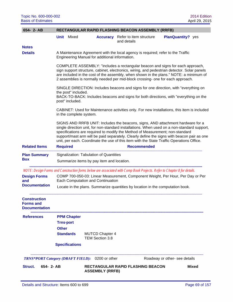
Topic No. 600-000-002Basis of Estimates
2014 EditionApril 29, 2015
654- 2- AB RECTANGULAR RAPID FLASHING BEACON ASSEMBLY (RRFB)
Unit Mixed Accuracy Refer to item structure and details
PlanQuantity? yes
A Maintenance Agreement with the local agency is required; refer to the Traffic Engineering Manual for additional information.
COMPLETE ASSEMBLY: "includes a rectangular beacon and signs for each approach, sign support structure, cabinet, electronics, wiring, and pedestrian detector. Solar panels are included in the cost of the assembly, when shown in the plans." NOTE: a minimum of 2 assemblies is normally needed per mid-block crossing- one for each approach.
SINGLE DIRECTION: Includes beacons and signs for one direction, with "everything on the post" included.BACK-TO-BACK: Includes beacons and signs for both directions, with "everything on the post" included.
CABINET: Used for Maintenance activities only. For new installations, this item is included in the complete system.
SIGNS AND RRFB UNIT: Includes the beacons, signs, AND attachment hardware for a single direction unit, for non-standard installations. When used on a non-standard support, specifications are required to modify the Method of Measurement; non-standard support/mast arm will be paid separately. Clearly define the signs with beacon pair as one unit, per each. Coordinate the use of this item with the State Traffic Operations Office.
Required Recommended
Standards MUTCD Chapter 4TEM Section 3.8
Specifications
Struct. 654- 2- AB RECTANGULAR RAPID FLASHING BEACON ASSEMBLY (RRFB)
Mixed
Details
Related Items
Design Forms and Documentation
PPM Chapter
Notes
References
COMP 700-050-03: Linear Measurement, Component Weight, Per Hour, Per Day or Per Each Computation and Continuation
Locate in the plans. Summarize quantities by location in the computation book.
Trns·port
TRNS*PORT Category (DRAFT FIELD): 0200 or other Roadway or other- see details
Other
Construction Forms and Documentation
Plan Summary Box
Signalization: Tabulation of Quantities
Summarize items by pay item and location.
NOTE: Design Forms and Construction forms below are associated with Comp Book Projects. Refer to Chapter 8 for details.
Page 69 of 157Details and Structure: Items 600 to 699
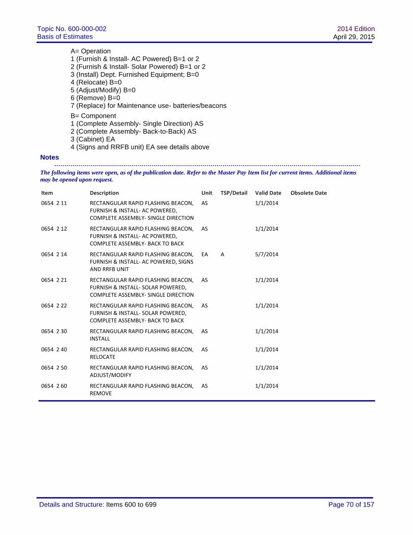
Topic No. 600-000-002Basis of Estimates
2014 EditionApril 29, 2015
A= Operation1 (Furnish & Install- AC Powered) B=1 or 22 (Furnish & Install- Solar Powered) B=1 or 23 (Install) Dept. Furnished Equipment; B=04 (Relocate) B=05 (Adjust/Modify) B=06 (Remove) B=07 (Replace) for Maintenance use- batteries/beacons
B= Component1 (Complete Assembly- Single Direction) AS2 (Complete Assembly- Back-to-Back) AS3 (Cabinet) EA4 (Signs and RRFB unit) EA see details above
Notes
The following items were open, as of the publication date. Refer to the Master Pay Item list for current items. Additional items may be opened upon request.
Item Description Unit TSP/Detail Valid Date Obsolete Date
0654 2 11 RECTANGULAR RAPID FLASHING BEACON, FURNISH & INSTALL‐ AC POWERED, COMPLETE ASSEMBLY‐ SINGLE DIRECTION
AS 1/1/2014
0654 2 12 RECTANGULAR RAPID FLASHING BEACON, FURNISH & INSTALL‐ AC POWERED, COMPLETE ASSEMBLY‐ BACK TO BACK
AS 1/1/2014
0654 2 14 RECTANGULAR RAPID FLASHING BEACON, FURNISH & INSTALL‐ AC POWERED, SIGNS AND RRFB UNIT
EA A 5/7/2014
0654 2 21 RECTANGULAR RAPID FLASHING BEACON, FURNISH & INSTALL‐ SOLAR POWERED, COMPLETE ASSEMBLY‐ SINGLE DIRECTION
AS 1/1/2014
0654 2 22 RECTANGULAR RAPID FLASHING BEACON, FURNISH & INSTALL‐ SOLAR POWERED, COMPLETE ASSEMBLY‐ BACK TO BACK
AS 1/1/2014
0654 2 30 RECTANGULAR RAPID FLASHING BEACON, INSTALL
AS 1/1/2014
0654 2 40 RECTANGULAR RAPID FLASHING BEACON, RELOCATE
AS 1/1/2014
0654 2 50 RECTANGULAR RAPID FLASHING BEACON, ADJUST/MODIFY
AS 1/1/2014
0654 2 60 RECTANGULAR RAPID FLASHING BEACON, REMOVE
AS 1/1/2014
Page 70 of 157Details and Structure: Items 600 to 699

Topic No. 600-000-002Basis of Estimates
2014 EditionApril 29, 2015
654- 3- AB PEDESTRIAN HYBRID BEACON ASSEMBLY
Unit Mixed Accuracy Refer to item structure and details
PlanQuantity? yes
A Maintenance Agreement with the local agency is required; refer to the Traffic Engineering Manual for additional information.
The Pedestrian Hybrid Beacon Assembly is the 3-section signal.
COMPLETE ASSEMBLY: "the assembly includes the 3-section signal, hardware, and backplate." NOTE: a minimum of 2 signal assemblies are required per approach.
SEPARATE PAY ITEMS ARE REQUIRED FOR pedestrian signals, cabinet, signs, mast arms, strain poles, or other support structures, and signal cable.
Required Recommended
Standards MUTCD Chapter 4TEM Section 3.8
Specifications
Struct. 654- 3- AB PEDESTRIAN HYBRID BEACON ASSEMBLY Mixed
A= Operation1 (Furnish & Install) B=03 (Install) Dept. Furnished Equipment; B=04 (Relocate) B=05 (Adjust/Modify) B=06 (Remove) B=07 (Replace) B=0, Maintenance use only
B= Component0 (Complete Assembly) 3-section signal; AS
Notes
Details
Related Items
Design Forms and Documentation
PPM Chapter
Notes
References
COMP 700-050-03: Linear Measurement, Component Weight, Per Hour, Per Day or Per Each Computation and Continuation
Locate in the plans. Summarize quantities by location in the computation book.
Trns·port
TRNS*PORT Category (DRAFT FIELD): 0200 or other Roadway or other- see details
Other
Construction Forms and Documentation
Plan Summary Box
Signalization: Tabulation of Quantities
Summarize items by pay item and location.
NOTE: Design Forms and Construction forms below are associated with Comp Book Projects. Refer to Chapter 8 for details.
Page 71 of 157Details and Structure: Items 600 to 699

Topic No. 600-000-002Basis of Estimates
2014 EditionApril 29, 2015
The following items were open, as of the publication date. Refer to the Master Pay Item list for current items. Additional items may be opened upon request.
Item Description Unit TSP/Detail Valid Date Obsolete Date
0654 3 10 PEDESTRIAN HYBRID BEACON ASSEMBLY, FURNISH & INSTALL COMPLETE ASSEMBLY
AS 1/1/2014
0654 3 60 PEDESTRIAN HYBRID BEACON ASSEMBLY, REMOVE
AS 1/1/2014
Page 72 of 157Details and Structure: Items 600 to 699

Topic No. 600-000-002Basis of Estimates
2014 EditionApril 29, 2015
659- 1-ABB MAST ARM, SPAN WIRE, AND POLE MOUNTING ASSEMBLIES
Unit EA Accuracy Each PlanQuantity?
Effective January 2015, for RETROFIT/REPLACEMENT of mounting assemblies.
Refer to 650-2 for other signal auxiliaries.
NO SEPARATE PAYMENT will be made for hangers on new signal installations. This item is valid for repair /replacement /retrofit applications only.
Required Recommended
Standards
Specifications
Struct. 659- 1-ABB MAST ARM, SPAN WIRE, AND POLE MOUNTING ASSEMBLIES
EA
A= Operation1 (Repair/Replace/Retrofit- Furnish & Install) NOT for use with new signal assemblies3 (Repair/Replace/Retrofit- Install) Item furnished by local agency
BB= Component1 (Mast Arm Mounting Assembly) "Hanger"2 (Span Wire Mounting Assembly) "Hanger"3 (Pole Mounting Assembly)Other components, as requested
Notes
Details
Related Items
Design Forms and Documentation
PPM Chapter
Notes
References
Trns·port
TRNS*PORT Category (DRAFT FIELD): 0500 Signalization (or ITS)
The following items were open, as of the publication date. Refer to the Master Pay Item list for current items. Additional items may be opened upon request.
Other
Construction Forms and Documentation
Plan Summary Box
Signalization: Tabulation of Quantities
Summarize items by pay item and location.
NOTE: Design Forms and Construction forms below are associated with Comp Book Projects. Refer to Chapter 8 for details.
Page 73 of 157Details and Structure: Items 600 to 699

Topic No. 600-000-002Basis of Estimates
2014 EditionApril 29, 2015
Item Description Unit TSP/Detail Valid Date Obsolete Date
0659 1101 MOUNTING ASSEMBLY, REPAIR/REPLACE/RETRO‐ FURNISH & INSTALL, MAST ARM MOUNTING ASSEMBLY
EA 1/1/2015
0659 1102 MOUNTING ASSEMBLY, REPAIR/REPLACE/RETRO‐ FURNISH & INSTALL, MAST ARM MOUNTING ASSEMBLY
EA 1/1/2015
Page 74 of 157Details and Structure: Items 600 to 699
Topic No. 600-000-002Basis of Estimates
2014 EditionApril 29, 2015
659- A- BB SIGNAL HEAD- RETROFIT AUXILIARIES
Unit EA Accuracy Each PlanQuantity? no
Valid through 12-31-2014. Replaced by 659-1-ABB (Hanger), and 650-2- items.
This pay item is for the retrofit of traffic signals and traffic control devices only. Refer to Minimum Specifications for Traffic Control Signal Devices, as applicable. NOTE: Auxiliary Items for new installations are included in the Traffic Signal assembly.
INSTALL: Items to be furnished by FDOT or local/maintaining agency.
Required Recommended
Standards
Specifications Min Specs: Section A659
http://www.dot.state.fl.us/specificationsoffice/Implemented/SpecBooks
Struct. 659- A- BB SIGNAL HEAD- RETROFIT AUXILIARIES EA
A = Operation1 (Furnish & Install)3 (Install) item furnished by local agency
BB = RETROFIT Item01 (Backplate – Black)02 (Backplate – Black with Retroreflective Border)03 (Disconnect Hanger)04 (Pivotal Hanger Assembly)05 (Tunnel Visor)06 (12" LED Module – Standard)07 (8" LED Module – Emergency Signal)
Notes
Details
Record final quantity on the tabulation sheet (plans) or computation form (comp book).
Related Items
Design Forms and Documentation
PPM Chapter
Notes
References
tabqsg: Signalization Tabulation of Quantity Sheet
Locate in plans. Summarize quantities by location on summary sheet in the plans.
No additional form required; use plans summary or comp book
Trns·port
TRNS*PORT Category (DRAFT FIELD): 0500 Signalization (or ITS)
The following items were open, as of the publication date. Refer to the Master Pay Item list for current items. Additional items may be opened upon request.
Other
Construction Forms and Documentation
Plan Summary Box
Signalization: Tabulation of Quantities
Summarize items by pay item and location.
NOTE: Design Forms and Construction forms below are associated with Comp Book Projects. Refer to Chapter 8 for details.
Page 75 of 157Details and Structure: Items 600 to 699

Topic No. 600-000-002Basis of Estimates
2014 EditionApril 29, 2015
660- 1-ABB LOOP DETECTOR, INDUCTIVE
Unit EA Accuracy Each PlanQuantity? no
This pay item is for traffic control devices, including traffic signals and ITS devices. Refer to Minimum Specifications for Traffic Control Signal Devices, as applicable.
Use with pay item 660-2.DO NOT USE with other types of vehicle detectors, pay items 660-3 through 660-6.
REMOVE- Cabinet to remain: This pay item is to be used only when the cabinet is to remain. When the entire cabinet is to be removed, payment is included under the controller assembly (Cabinet, controller, and incidentals).
RELOCATE: This pay items is to be used when the Controller is relocated to a new cabinet. Show/detail the locations in the plans or summary box.
Required Recommended
Standards
Specifications Min Specs: Section A660
http://www.dot.state.fl.us/specificationsoffice/Implemented/SpecBooks
Struct. 660- 1-ABB LOOP DETECTOR, INDUCTIVE EA
A = Operation1 (Furnish & Install)3 (Install) BB=00, Furnished by FDOT or Maintaining Agency4 (Relocate) BB=006 (Remove- cabinet to remain) BB=00
BB = Type01 (Type 1, 1 Ch, R, S)02 (Type 2, 1 Ch, R, S, TD)03 (Type 3, 1 Ch, SS, S))04 (Type 4, 1 Ch, SS, S, TD)05 (Type 5, 2 Ch, SS, S)06 (Type 6, 2 Ch, SS, S, TD)
Details
Record final quantity on the tabulation sheet (plans) or computation form (comp book).
Related Items
Design Forms and Documentation
PPM Chapter
Notes
References
tabqsg: Signalization Tabulation of Quantity Sheet
Locate in plans. Summarize quantities by location on summary sheet in the plans.
No additional form required; use plans summary or comp book
Trns·port
TRNS*PORT Category (DRAFT FIELD): 0500 Signalization (or ITS)
Other
Construction Forms and Documentation
Plan Summary Box
Signalization: Tabulation of Quantities
Summarize items by pay item and location.
NOTE: Design Forms and Construction forms below are associated with Comp Book Projects. Refer to Chapter 8 for details.
Page 76 of 157Details and Structure: Items 600 to 699

Topic No. 600-000-002Basis of Estimates
2014 EditionApril 29, 2015
07 (Type 7, 4 Ch, SS, S)08 (Type 8, 4 Ch, SS, S, TD)09 (Type 9, 2 Ch, SS, RM)10 (Type 10, 2 Ch, SS, RM, TD)11 (Type 11, 4 Ch, SS, RM)12 (Type 12, 4 Ch, SS, RM, TD) Legend Ch = Channel R = Relay Output S = Shelf Mounted TD = Time Delay RM = Rack Mounted SS = Solid State
Notes
The following items were open, as of the publication date. Refer to the Master Pay Item list for current items. Additional items may be opened upon request.
Item Description Unit TSP/Detail Valid Date Obsolete Date
0660 1101 LOOP DETECTOR INDUCTIVE, F&I, TYPE 1 EA 1/1/2013
0660 1102 LOOP DETECTOR INDUCTIVE, F&I, TYPE 2 EA 1/1/2013
0660 1103 LOOP DETECTOR INDUCTIVE, F&I, TYPE 3 EA 1/1/2013
0660 1104 LOOP DETECTOR, INDUCTIVE, F&I, TYPE 4, 2CHANNEL, SOLID STATE, SHELF MOUNTED, TIME DELAY
EA 1/1/2013
0660 1105 LOOP DETECTOR, INDUCTIVE, F&I, TYPE 5, 2CHANNEL, SOLID STATE, SHELF MOUNTED
EA 1/1/2013
0660 1106 LOOP DETECTOR INDUCTIVE , F&I, TYPE 6, 2 CH,SS,S,TD
EA 1/1/2013
0660 1107 LOOP DETECTOR INDUCTIVE , F&I, TYPE 7, 4 CH,SS,S
EA 1/1/2013
0660 1109 LOOP DETECTOR INDUCTIVE, F&I, TYPE 9 EA 1/1/2013
0660 1110 LOOP DETECTOR INDUCTIVE, F&I, TYPE 10 EA 1/1/2013
0660 1111 LOOP DETECTOR INDUCTIVE, F&I, TYPE 11, 4 CH, SS, RM
EA 1/1/2013
0660 1112 LOOP DETECTOR INDUCTIVE, F&I, TYPE 12, 4 CH, SS, RM, TD
EA 1/1/2013
0660 1300 LOOP DETECTOR INDUCTIVE, INSTALL EA 1/1/2013
0660 1400 LOOP DETECTOR INDUCTIVE, RELOCATE EA 1/1/2015
0660 1600 LOOP DETECTOR INDUCTIVE, REMOVE‐ CABINET TO REMAIN
EA 1/1/2015
Page 77 of 157Details and Structure: Items 600 to 699

Topic No. 600-000-002Basis of Estimates
2014 EditionApril 29, 2015
660- 2-ABB LOOP ASSEMBLY
Unit AS Accuracy Assembly PlanQuantity? no
DO NOT USE FOR Traffic Monitoring Site loops.This pay item is for traffic control devices, including traffic signals and ITS devices. Refer to Minimum Specifications for Traffic Control Signal Devices, as applicable.
Includes cost of loop material, labor, etc. according to specifications.Use with pay item 660-1.DO NOT USE with other types of vehicle detectors, pay items 660-3 through 660-6
Required Recommended
Standards Index No. 17781
Specifications Min Specs: Section A660
http://www.dot.state.fl.us/specificationsoffice/Implemented/SpecBooks
Struct. 660- 2-ABB LOOP ASSEMBLY AS
A = Operation1 (Furnish & Install)
BB = Type01 (Type A)02 (Type B)03 (Type C)04 (Type D)05 (Type E)06 (Type F)07 (Type G)08 (Type H)
Notes
Details
Record final quantity on the tabulation sheet (plans) or computation form (comp book).
Related Items
Design Forms and Documentation
PPM Chapter
Notes
References
tabqsg: Signalization Tabulation of Quantity Sheet
Locate in plans. Summarize quantities by location on summary sheet in the plans.
No additional form required; use plans summary or comp book
Trns·port
TRNS*PORT Category (DRAFT FIELD): 0500 Signalization (or ITS)
The following items were open, as of the publication date. Refer to the Master Pay Item list for current items. Additional items may be opened upon request.
Other
Construction Forms and Documentation
Plan Summary Box
Signalization: Tabulation of Quantities
Summarize items by pay item and location.
NOTE: Design Forms and Construction forms below are associated with Comp Book Projects. Refer to Chapter 8 for details.
Page 78 of 157Details and Structure: Items 600 to 699

Topic No. 600-000-002Basis of Estimates
2014 EditionApril 29, 2015
Item Description Unit TSP/Detail Valid Date Obsolete Date
0660 2101 LOOP ASSEMBLY‐ F&I, TYPE A AS 1/1/2013
0660 2102 LOOP ASSEMBLY, F&I, TYPE B AS 1/1/2013
0660 2103 LOOP ASSEMBLY, F&I, TYPE C AS 1/1/2013
0660 2104 LOOP ASSEMBLY, F&I, TYPE D AS 1/1/2013
0660 2105 LOOP ASSEMBLY, F&I, TYPE E AS 1/1/2013
0660 2106 LOOP ASSEMBLY, F&I, TYPE F AS 1/1/2013
0660 2107 LOOP ASSEMBLY, F&I, TYPE G AS 1/1/2013
Page 79 of 157Details and Structure: Items 600 to 699

Topic No. 600-000-002Basis of Estimates
2014 EditionApril 29, 2015
660- 3- AB VEHICLE DETECTION SYSTEM- MICROWAVE
Unit EA Accuracy Each PlanQuantity? yes
This item is intended for Vehicle Detection Systems, excluding Loop Systems. Details such as location of detectors, detection zones, and roadside components must be detailed in the plans.
For Loop Systems, see 660-1 and 660-2 pay items.
Required Recommended
Standards
Specifications
Struct. 660- 3- AB VEHICLE DETECTION SYSTEM- MICROWAVE EA
A= Operation1 (Furnish & Install) B=1 or 23 (Install) Department furnished equipment 4 (Relocate)5 (Adjust/Modify)6 (Remove) B=0 8 (Preventative Maintenance) B=09 (Diagnosis and Misc. Repair) B=0
B= Component0 (Complete System)1 (Cabinet Equipment) Note: Pay item callout shall be used in plans to depict QTY and location of system components installed in cabinet.2 (Above ground Equipment) Note: Pay item callout shall be used in plans to depict QTY and location of sensor(s). Mounting hardware and cabling is considered incidental to sensor.
Notes
Details
Related Items
Design Forms and Documentation
PPM Chapter
Notes
References
COMP 700-050-03: Linear Measurement, Component Weight, Per Hour, Per Day or Per Each Computation and Continuation
Locate in the plans. Summarize quantities by location in the computation book.
Trns·port
TRNS*PORT Category (DRAFT FIELD): Multiple Roadway, Signals, Lighting, etc
The following items were open, as of the publication date. Refer to the Master Pay Item list for current items. Additional items may be opened upon request.
Other
Construction Forms and Documentation
Plan Summary Box
Signalization: Tabulation of Quantities
Summarize items by pay item and location.
NOTE: Design Forms and Construction forms below are associated with Comp Book Projects. Refer to Chapter 8 for details.
Page 80 of 157Details and Structure: Items 600 to 699

Topic No. 600-000-002Basis of Estimates
2014 EditionApril 29, 2015
Item Description Unit TSP/Detail Valid Date Obsolete Date
0660 3 11 VEHICLE DETECTION SYSTEM‐ MICROWAVE, FURNISH & INSTALL CABINET EQUIPMENT
EA 7/1/2013
0660 3 12 VEHICLE DETECTION SYSTEM‐ MICROWAVE, FURNISH & INSTALL, ABOVE GROUND EQUIPMENT
EA 7/1/2013
0660 3 31 VEHICLE DETECTION SYSTEM‐ MICROWAVE, INSTALL‐ FDOT FURNISHED CABINET EQUIPMENT
EA 7/1/2013
0660 3 32 VEHICLE DETECTION SYSTEM‐ MICROWAVE, INSTALL‐ FDOT FURNISHED, ABOVE GROUND EQUIPMENT
EA 7/1/2013
0660 3 40 VEHICLE DETECTION SYSTEM ‐ MICROWAVE, RELOCATE, COMPLETE SYSTEM
EA 7/1/2013
0660 3 42 VEHICLE DETECTION SYSTEM ‐ MICROWAVE, RELOCATE, ABOVE GROUND EQUIPMENT
EA 7/1/2013
0660 3 51 VEHICLE DETECTION SYSTEM‐ MICROWAVE, ADJUST & MODIFY, CABINET EQUIPMENT
EA 7/1/2013
0660 3 52 VEHICLE DETECTION SYSTEM ‐ MICROWAVE, ADJUST & MODIFY, ABOVE GROUND EQUIPMENT
EA 7/1/2013
0660 3 60 VEHICLE DETECTION SYSTEM ‐ MICROWAVE, REMOVE, COMPLETE SYSTEM
EA 7/1/2013
Page 81 of 157Details and Structure: Items 600 to 699

Topic No. 600-000-002Basis of Estimates
2014 EditionApril 29, 2015
660- 4- AB VEHICLE DETECTION SYSTEM- VIDEO
Unit EA Accuracy Each PlanQuantity? yes
This item is intended for Vehicle Detection Systems, excluding Loop Systems. Details such as location of detectors, detection zones, and roadside components must be detailed in the plans.
For Loop Systems, see 660-1 and 660-2 pay items.
Required Recommended
Standards
Specifications
Struct. 660- 4- AB VEHICLE DETECTION SYSTEM- VIDEO EA
A= Operation1 (Furnish & Install)3 (Install) Department furnished equipment4 (Relocate)5 (Adjust/Modify)6 (Remove) B=08 (Preventative Maintenance) B=09 (Diagnosis and Misc. Repair) B=0
B= Component0 (Complete System)1 (Cabinet Equipment ) Note: Pay item callout shall be used in plans to depict QTY and location of shelf-mount or detector-card style video processor(s). Supplemental interface hardware, cabling, and other system components are considered incidental to video processor(s). 2 (Above ground Equipment Note: Pay item callout shall be used in plans to depict QTY and location of camera(s). Mounting hardware and cabling is considered incidental to camera(s).
Notes
Details
Related Items
Design Forms and Documentation
PPM Chapter
Notes
References
COMP 700-050-03: Linear Measurement, Component Weight, Per Hour, Per Day or Per Each Computation and Continuation
Locate in the plans. Summarize quantities by location in the computation book.
Trns·port
TRNS*PORT Category (DRAFT FIELD): Multiple Roadway, Signals, Lighting, etc
Other
Construction Forms and Documentation
Plan Summary Box
Signalization: Tabulation of Quantities
Summarize items by pay item and location.
NOTE: Design Forms and Construction forms below are associated with Comp Book Projects. Refer to Chapter 8 for details.
Page 82 of 157Details and Structure: Items 600 to 699

Topic No. 600-000-002Basis of Estimates
2014 EditionApril 29, 2015
The following items were open, as of the publication date. Refer to the Master Pay Item list for current items. Additional items may be opened upon request.
Item Description Unit TSP/Detail Valid Date Obsolete Date
0660 4 10 VEHICLE DETECTION SYSTEM‐ VIDEO, F&I, COMPLETE SYSTEM
EA 7/8/2014 6/30/2015
0660 4 11 VEHICLE DETECTION SYSTEM‐ VIDEO, FURNISH & INSTALL CABINET EQUIPMENT
EA 7/1/2013
0660 4 12 VEHICLE DETECTION SYSTEM‐ VIDEO, FURNISH & INSTALL ABOVE GROUND EQUIPMENT
EA 7/1/2013
0660 4 41 VEHICLE DETECTION SYSTEM‐ VIDEO, RELOCATE CABINET EQUIPMENT
EA 7/1/2013
0660 4 42 VEHICLE DETECTION SYSTEM‐ VIDEO, RELOCATE ABOVE GROUND EQUIPMENT
EA 7/1/2013
0660 4 51 VEHICLE DETECTION SYSTEM‐ VIDEO, ADJUST/MODIFY CABINET EQUIPMENT
EA T 7/1/2013
0660 4 52 VEHICLE DETECTION SYSTEM‐ VIDEO, ADJUST/MODIFY ABOVE GROUND EQUIPMENT
EA T 7/1/2013
0660 4 60 VEHICLE DETECTION SYSTEM‐ VIDEO, REMOVE
EA T 7/1/2013
Page 83 of 157Details and Structure: Items 600 to 699

Topic No. 600-000-002Basis of Estimates
2014 EditionApril 29, 2015
660- 5- AB VEHICLE DETECTION SYSTEM- WIRELESS MAGNETOMETER
Unit EA Accuracy Each PlanQuantity? yes
This item is intended for Vehicle Detection Systems, excluding Loop Systems. Details such as location of detectors, detection zones, and roadside components must be detailed in the plans.
For Loop Systems, see 660-1 and 660-2 pay items.
Required Recommended
Standards
Specifications
Struct. 660- 5- AB VEHICLE DETECTION SYSTEM- WIRELESS MAGNETOMETER
EA
A= Operation1 (Furnish & Install)3 (Install) Department furnished equipment4 (Relocate)5 (Adjust/Modify)6 (Remove) B=08 (Preventative Maintenance) B=09 (Diagnosis and Misc. Repair) B=0
B= Component0 (Complete System) only for A=6, 8, or 91 (Cabinet Equipment) Note: Pay item callout shall be used in plans to indicate QTY and location of shelf mount or detector-card style cabinet interface hardware required. Cabling, and other system components are considered incidental to interface card(s).2 (Above ground Equipment) Note: Pay item callout shall be used in plans to indicate QTY and location of access point(s) or repeater(s) required. Mounting hardware and cabling is considered incidental to access point(s) and repeater(s). 3 (In-Road Electronics) Note: Pay item callout shall be used in plans to indicate QTY and location of wireless magnetometer sensors embedded in roadway
Details
Related Items
Design Forms and Documentation
PPM Chapter
Notes
References
COMP 700-050-03: Linear Measurement, Component Weight, Per Hour, Per Day or Per Each Computation and Continuation
Locate in the plans. Summarize quantities by location in the computation book.
Trns·port
TRNS*PORT Category (DRAFT FIELD): Multiple Roadway, Signals, Lighting, etc
Other
Construction Forms and Documentation
Plan Summary Box
Signalization: Tabulation of Quantities
Summarize items by pay item and location.
NOTE: Design Forms and Construction forms below are associated with Comp Book Projects. Refer to Chapter 8 for details.
Page 84 of 157Details and Structure: Items 600 to 699

Topic No. 600-000-002Basis of Estimates
2014 EditionApril 29, 2015
Notes
The following items were open, as of the publication date. Refer to the Master Pay Item list for current items. Additional items may be opened upon request.
Item Description Unit TSP/Detail Valid Date Obsolete Date
0660 5 11 VEHICLE DETECTION SYSTEM‐ WIRELESS MAGNETOMETER, FURNISH & INSTALL, CABINET EQUIPMENT
EA 7/1/2013
0660 5 12 VEHICLE DETECTION SYSTEM‐ WIRELESS MAGNETOMETER, FURNISH & INSTALL, ABOVE GROUND EQUIPMENT
EA 7/1/2013
0660 5 13 VEHICLE DETECTION SYSTEM‐ WIRELESS MAGNETOMETER, FURNISH & INSTALL, IN‐ROAD ELECTRONICS
EA 7/1/2013
0660 5 41 VEHICLE DETECTION SYSTEM‐ WIRELESS MAGNETOMETER, RELOCATE, CABINET EQUIPMENT
EA 7/1/2013
0660 5 42 VEHICLE DETECTION SYSTEM‐ WIRELESS MAGNETOMETER, RELOCATE, ABOVE GROUND EQUIPMENT
EA 7/1/2013
0660 5 43 VEHICLE DETECTION SYSTEM‐ WIRELESS MAGNETOMETER, RELOCATE, IN‐ROAD ELECTRONICS
EA 7/1/2013
0660 5 60 VEHICLE DETECTION SYSTEM‐ WIRELESS MAGNETOMETER, REMOVE
EA 7/1/2013
Page 85 of 157Details and Structure: Items 600 to 699

Topic No. 600-000-002Basis of Estimates
2014 EditionApril 29, 2015
660- 6-ABC VEHICLE DETECTION SYSTEM- AVI "Automatic Vehicle Identification"
Unit EA Accuracy Each PlanQuantity? yes
This item is intended for Vehicle Detection Systems, excluding Loop Systems. Details such as location of detectors, detection zones, and roadside components must be detailed in the plans.
For Loop Systems, see 660-1 and 660-2 pay items.
Required Recommended
Standards
Specifications
Struct. 660- 6-ABC VEHICLE DETECTION SYSTEM- AVI "Automatic Vehicle Identification"
EA
A= Operation1 (Furnish & Install)3 (Install) Department furnished equipment4 (Relocate)5 (Adjust/Modify)6 (Remove) BC=008 (Preventative Maintenance) BC=009 (Diagnosis and Misc. Repair) BC=00
B= System Type1 (Transponder)2 (Bluetooth) 3 (License Plate)
C= Component0 (Complete System) only for A=8, 91 (Cabinet Equipment) Note: Pay item callout shall be used in plans to depict QTY and location of processing equipment. Supplemental interface hardware, cabling, and other system components are considered incidental to processing hardware.2 (Above ground Equipment) Note: Pay item callout shall be used in plans to depict QTY and
Details
Related Items
Design Forms and Documentation
PPM Chapter
Notes
References
COMP 700-050-03: Linear Measurement, Component Weight, Per Hour, Per Day or Per Each Computation and Continuation
Locate in the plans. Summarize quantities by location in the computation book.
Trns·port
TRNS*PORT Category (DRAFT FIELD): Multiple Roadway, Signals, Lighting, etc
Other
Construction Forms and Documentation
Plan Summary Box
Signalization: Tabulation of Quantities
Summarize items by pay item and location.
NOTE: Design Forms and Construction forms below are associated with Comp Book Projects. Refer to Chapter 8 for details.
Page 86 of 157Details and Structure: Items 600 to 699

Topic No. 600-000-002Basis of Estimates
2014 EditionApril 29, 2015
location of cameras required by license plate system, QTY and location of antennas required by transponder or Bluetooth® systems. Additional pole-mounted hardware is considered incidental to camera(s) or antenna(s).
Notes
The following items were open, as of the publication date. Refer to the Master Pay Item list for current items. Additional items may be opened upon request.
Item Description Unit TSP/Detail Valid Date Obsolete Date
0660 6111 VEHICLE DETECTION SYSTEM‐ AVI, TRANSPONDER, FURNISH & INSTALL, CABINET EQUIPMENT
EA 7/1/2013
0660 6112 VEHICLE DETECTION SYSTEM‐ AVI, TRANSPONDER, FURNISH & INSTALL, ABOVE GROUND EQUIPMENT
EA 7/1/2013
0660 6121 VEHICLE DETECTION SYSTEM‐ AVI, BLUETOOTH, FURNISH & INSTALL, CABINET EQUIPMENT
EA 7/1/2013
0660 6122 VEHICLE DETECTION SYSTEM‐ AVI, BLUETOOTH, FURNISH & INSTALL, ABOVE GROUND EQUIPMENT
EA 7/1/2013
0660 6321 VEHICLE DETECTION SYSTEM‐ AVI, BLUETOOTH, INSTALL‐ FDOT FURNISHED, CABINET EQUIPMENT
EA 7/1/2013
0660 6322 VEHICLE DETECTION SYSTEM‐ AVI, BLUETOOTH INSTALL, ABOVE GROUND EQUIPMENT
EA 7/1/2013
0660 6411 VEHICLE DETECTION SYSTEM‐ AVI, TRANSPONDER RELOCATE, CABINET EQUIPMENT
EA 7/1/2013
0660 6412 VEHICLE DETECTION SYSTEM‐ AVI, TRANSPONDER RELOCATE, ABOVE GROUND EQUIPMENT
EA 7/1/2013
0660 6421 VEHICLE DETECTION SYSTEM‐ AVI, BLUETOOTH RELOCATE, CABINET EQUIPMENT
EA 7/1/2013
0660 6422 VEHICLE DETECTION SYSTEM‐ AVI, BLUETOOTH RELOCATE, ABOVE GROUND EQUIPMENT
EA 7/1/2013
0660 6500 VEHICLE DETECTION SYSTEM‐ AVI, ADJUST/MODIFY COMPLETE SYSTEM
EA 7/1/2013
0660 6600 VEHICLE DETECTION SYSTEM‐ AVI, REMOVE COMPLETE SYSTEM
EA P 7/1/2013
Page 87 of 157Details and Structure: Items 600 to 699

Topic No. 600-000-002Basis of Estimates
2014 EditionApril 29, 2015
663- 1-ABC SIGNAL PRIORITY AND PREEMPTION SYSTEM
Unit EA Accuracy Each PlanQuantity? no
This item is intended for bus and emergency vehicle pre-emption.
Tech Specs and/or plan details will be required, until specifications are available (expected July 2015 letting).
Required Recommended
Standards
Specifications
Struct. 663- 1-ABC SIGNAL PRIORITY AND PREEMPTION SYSTEM EA
A=Operation1 (Furnish & Install) C=03 (Install)4 (Relocate) BC=005 (Adjust/Modify) BC=006 (Remove) BC=00
B= Type1 (Optical)2 (GPS)3 (Radio Frequency)
C= Components0 (Complete System)1 (Cabinet Electronics)2 (Detector)
Notes
Details
Related Items
Design Forms and Documentation
PPM Chapter
Notes
References
Trns·port
TRNS*PORT Category (DRAFT FIELD): 0200 or other Roadway or other- see details
The following items were open, as of the publication date. Refer to the Master Pay Item list for current items. Additional items may be opened upon request.
Other
Construction Forms and Documentation
Plan Summary Box
Signalization: Tabulation of Quantities
Summarize items by pay item and location.
NOTE: Design Forms and Construction forms below are associated with Comp Book Projects. Refer to Chapter 8 for details.
Page 88 of 157Details and Structure: Items 600 to 699

Topic No. 600-000-002Basis of Estimates
2014 EditionApril 29, 2015
Item Description Unit TSP/Detail Valid Date Obsolete Date
0663 1110 SIGNAL PRIORITY AND PREEMPTION SYSTEM, F&I, OPTICAL, COMPLETE SYSTEM
EA T 7/1/2013
0663 1111 SIGNAL PRIORITY AND PREEMPTION SYSTEM, F&I, OPTICAL, CABINET ELECTRONICS
EA 7/1/2013 6/30/2015
0663 1112 SIGNAL PRIORITY AND PREEMPTION SYSTEM, F&I, OPTICAL, DETECTOR
EA 7/1/2013 6/30/2015
0663 1120 SIGNAL PRIORITY AND PREEMPTION SYSTEM, FURNISH AND INSTALL, GPS, COMPLETE SYSTEM
EA T 7/1/2013
0663 1129 SIGNAL PRIORITY AND PREEMPTION SYSTEM, FURNISH AND INSTALL, GPS, EMITTER FOR BUS
EA T 7/1/2013 6/30/2015
0663 1400 SIGNAL PRIORITY & PREEMPTION SYSTEM, RELOCATE
EA P 7/1/2013
0663 1500 SIGNAL PRIORITY & PREEMPTION SYSTEM, ADJUST/MODIFY
EA T 7/1/2013
0663 1600 SIGNAL PRIORITY & PREEMPTION SYSTEM, REMOVE
EA 7/1/2013
Page 89 of 157Details and Structure: Items 600 to 699

Topic No. 600-000-002Basis of Estimates
2014 EditionApril 29, 2015
665- 1- AB PEDESTRIAN DETECTOR
Unit EA Accuracy Each PlanQuantity? no
Pedestrian detectors may be mounted on poles, posts, or pedestals, in accordance with the Design Standards. Payment includes pedestrian information signs/sticker, as shown on index 17784. Additional design guidance is available in MUTCD Section 4E.
Note: Poles, posts, and pedestals are paid separately under 641-, 646-, or 649-.
INSTALL: Detector and Sign to be furnished by FDOT or Maintaining agency. Plans or Specs must indicate pick-up or delivery instructions. Incidental parts to complete the installation to be furnished by the contractor.
RELOCATE: Ensure that plans/specs detail removal and re-installation instructions, as well as guidance if detector is damaged or broken.
REMOVE- POLE/PEDESTAL TO REMAIN: Equipment becomes the property of the contractor, unless otherwise shown in the plans. Note- No separate payment for removal of pedestrian detector when pole/pedestal is removed (included with pole removal).
Required Recommended
Standards Index 17784MUTCD
Specifications
Struct. 665- 1- AB PEDESTRIAN DETECTOR EA
A= Operation1 (Furnish & Install)3 (Install) Dept. Furnished Equipment; B=04 (Relocate) B=05 (Adjust/Modify) B=06 (Remove- Pole/Pedestal to Remain) B=0 8 (Preventative Maintenance) B=09 (Diagnosis and Misc. Repair) B=0
Details
Related Items
Design Forms and Documentation
PPM Chapter
Notes
References
tabqsg: Signalization Tabulation of Quantity Sheet
Locate in plans. Summarize quantities by location on summary sheet in the plans.
Trns·port
TRNS*PORT Category (DRAFT FIELD): 0500 Signalization (or ITS)
Other
Construction Forms and Documentation
Plan Summary Box
Signalization: Tabulation of Quantities
Summarize items by pay item and location.
NOTE: Design Forms and Construction forms below are associated with Comp Book Projects. Refer to Chapter 8 for details.
Page 90 of 157Details and Structure: Items 600 to 699

Topic No. 600-000-002Basis of Estimates
2014 EditionApril 29, 2015
B= Type1 (Standard)2 (Accessible)
Notes
The following items were open, as of the publication date. Refer to the Master Pay Item list for current items. Additional items may be opened upon request.
Item Description Unit TSP/Detail Valid Date Obsolete Date
0665 1 11 PEDESTRIAN DETECTOR, FURNISH & INSTALL, STANDARD
EA 1/1/2014
0665 1 12 PEDESTRIAN DETECTOR, FURNISH & INSTALL, ACCESSIBLE
EA 1/1/2014
0665 1 30 PEDESTRIAN DETECTOR, INSTALL EA 1/1/2014
0665 1 40 PEDESTRIAN DETECTOR, RELOCATE EA 1/1/2014
0665 1 60 PEDESTRIAN DETECTOR, REMOVE‐ POLE/PEDESTAL TO REMAIN
EA 1/1/2014
Page 91 of 157Details and Structure: Items 600 to 699
Topic No. 600-000-002Basis of Estimates
2014 EditionApril 29, 2015
670- 4- A INTERSECTION CONTROL BEACON CONTROLLER ASSEMBLY (Formerly Flashing Beacon Controller Assembly)
Unit AS Accuracy Assembly PlanQuantity? no
This pay item is for Intersection Control Beacon Assembly only.Note that the controller assembly includes both the controller electronics and the cabinet.
NOT VALID for use with school zone or warning signs.For sign beacons, refer to pay item 700-12. For Midblock crossings, refer to 654- pay items.
Intersection control beacons are described in the MUTCD, Section 4L.02 as " .. . One or more signal faces directed toward each approach to an intersection. Each signal face shall consist of one or more signal sections of a standard traffic signal face, with flashing CIRCULAR YELLO W or CIRCULAR RED signal indications in each signal face. They shall be installed and used only at an intersection to control two or more directions of travel. "
When installing an intersection control beacon, the following specs and pay items are applicable:650: Traffic Signals (1 section, 3 or 4 way)670: Traffic Controller Assembly (this item, described above)Poles, cables, and conduit.
Required Recommended
Standards Index No. 17841
Specifications Min Specs: Section A670
http://www.dot.state.fl.us/specificationsoffice/Implemented/SpecBooks
Struct. 670- 4- A INTERSECTION CONTROL BEACON CONTROLLER ASSEMBLY (Formerly Flashing Beacon Controller Assembly)
AS
A =1 (Furnish & Install)
Details
Record final quantity on the tabulation sheet (plans) or computation form (comp book).
Related Items
Design Forms and Documentation
PPM Chapter
Notes
References
tabqsg: Signalization Tabulation of Quantity Sheet
Locate in plans. Summarize quantities by location on summary sheet in the plans.
No additional form required; use plans summary or comp book
Trns·port
TRNS*PORT Category (DRAFT FIELD): 0500 Signalization (or ITS)
Other
Construction Forms and Documentation
Plan Summary Box
Signalization: Tabulation of Quantities
Summarize items by pay item and location.
NOTE: Design Forms and Construction forms below are associated with Comp Book Projects. Refer to Chapter 8 for details.
Page 92 of 157Details and Structure: Items 600 to 699

Topic No. 600-000-002Basis of Estimates
2014 EditionApril 29, 2015
Notes
The following items were open, as of the publication date. Refer to the Master Pay Item list for current items. Additional items may be opened upon request.
Item Description Unit TSP/Detail Valid Date Obsolete Date
0670 4 1 INTERSECTION CONTROL BEACON CONTROLLER ASSEMBLY, FURNISH & INSTALL
AS 1/1/2013
Page 93 of 157Details and Structure: Items 600 to 699

Topic No. 600-000-002Basis of Estimates
2014 EditionApril 29, 2015
670- 5-ABC TRAFFIC CONTROLLER ASSEMBLY (Controller with cabinet)
Unit AS Accuracy Assembly PlanQuantity? no
Remove item effective January 2015; replaces 690-50.
This pay item is for traffic control devices, including traffic signals and ITS devices.Note that the controller assembly includes both the controller electronics and the cabinet.
FURNISH & INSTALL: includes all work and materials to set-up controller in the cabinet.
MODIFY: Tech specs required to detail work to be completed. DO NOT USE this pay item for set-up of new controllers.For Special Type, detail all components.
REMOVE: Includes the removal of the cabinet, all electronics, and base/foundation.
For Plan Detail/Tech Spec items: The Designer should ensure that the description, materials, construction/installation requirements, method of measurement and basis of payment are available in the contract documents to clearly define the work to be completed for payment under this item.
Required Recommended
Standards
Specifications Min Specs: Section A670
http://www.dot.state.fl.us/specificationsoffice/Implemented/SpecBooks
Struct. 670- 5-ABC TRAFFIC CONTROLLER ASSEMBLY (Controller with cabinet)
AS
A = Operation1 (Furnish & Install)3 (Install) BC=00; FDOT furnished4 (Modify) BC=00; DO NOT USE with a new controller5 (Relocate Controller and Cabinet) BC=00
T: Selected Items may require Plan Details and/or Technical Specifications
Details
Record final quantity on the tabulation sheet (plans) or computation form (comp book).
Related Items
Design Forms and Documentation
PPM Chapter
Notes
References
tabqsg: Signalization Tabulation of Quantity Sheet
Locate in plans. Summarize quantities by location on summary sheet in the plans.
No additional form required; use plans summary or comp book
Trns·port
TRNS*PORT Category (DRAFT FIELD): 0500 Signalization (or ITS)
Other
Construction Forms and Documentation
Plan Summary Box
Signalization: Tabulation of Quantities
Summarize items by pay item and location.
NOTE: Design Forms and Construction forms below are associated with Comp Book Projects. Refer to Chapter 8 for details.
Page 94 of 157Details and Structure: Items 600 to 699

Topic No. 600-000-002Basis of Estimates
2014 EditionApril 29, 2015
6 (Remove Controller and Cabinet) BC=00 effective 1-1-15
B = Cabinet with Controller Type1 (NEMA)2 (Model 170)3 (Special) Valid through 12-31-144 (Model 2070) Effective 1-1-145 (ATC) Effective 1-1-14
C = Special Features0 (None)1 (One Preemption Plan)2 (Two Preemption Plans)
Notes
The following items were open, as of the publication date. Refer to the Master Pay Item list for current items. Additional items may be opened upon request.
Item Description Unit TSP/Detail Valid Date Obsolete Date
0670 5110 TRAFFIC CONTROLLER ASSEMBLY, F&I, NEMA
AS 1/1/2013
0670 5111 TRAFFIC CONTROLLER ASSEMBLY, F&I, NEMA, 1 PREEMPTION
AS 1/1/2013
0670 5112 TRAFFIC CONTROLLER ASSEMBLY, F&I, NEMA, 2 PREEMPTION
AS 1/1/2013
0670 5120 TRAFFIC CONTROLLER ASSEMBLY, F&I, 170 AS 1/1/2013
0670 5121 TRAFFIC CONTROLLER ASSEMBLY, F&I, 170, 1 PREEMPTION PLAN
AS 1/1/2013
0670 5122 TRAFFIC CONTROLLER ASSEMBLY, F&I,170,2 PREEMPTION PLANS
AS 1/1/2013
0670 5140 TRAFFIC CONTROLLER ASSEMBLY, FURNISH & INSTALL MODEL 2070
AS 1/1/2014
0670 5141 TRAFFIC CONTROLLER ASSEMBLY, FURNISH & INSTALL, MODEL 2070, 1 PREEMPTION
AS 1/1/2014
0670 5142 TRAFFIC CONTROLLER ASSEMBLY, FURNISH & INSTALL, MODEL 2070, 2 PREEMPTION
AS 1/1/2014
0670 5151 TRAFFIC CONTROLLER ASSEMBLY, FURNISH & INSTALL, ATC, 1 PREEMPTION
AS 1/1/2014
0670 5300 TRAFFIC CONTROLLER ASSEMBLY, INSTALL AS 1/1/2013
0670 5400 TRAFFIC CONTROLLER ASSEMBLY, MODIFY AS P 1/1/2013
0670 5500 TRAFFIC CONTROLLER ASSEMBLY, RELOCATE CONTROLLER WITH CABINET
AS P 1/1/2013
0670 5600 TRAFFIC CONTROLLER ASSEMBLY, REMOVE CONTROLLER WITH CABINET
AS 1/1/2015
Page 95 of 157Details and Structure: Items 600 to 699

Topic No. 600-000-002Basis of Estimates
2014 EditionApril 29, 2015
671- 2- AB TRAFFIC CONTROLLER (without cabinet)
Unit EA Accuracy Each PlanQuantity? no
For Traffic Controller with cabinet, see Traffic Controller Assembly, pay item 670-5-.
This pay item is for traffic control devices, including traffic signals and ITS devices. For repairs/replacement of controller component without cabinet, contact the BOE Coordinator for additional pay items.
Required Recommended
Standards
Specifications Min Specs: Section A671
http://www.dot.state.fl.us/specificationsoffice/Implemented/SpecBooks
Struct. 671- 2- AB TRAFFIC CONTROLLER (without cabinet) EA
A =1 (Furnish & Install)3 (Install) B=04 (Modify) B=05 (Relocate Controller without cabinet) move to a new cabinet; B=0
B = Type1 (NEMA)2 (170)4 (2070)
Notes
Details
Record final quantity on the tabulation sheet (plans) or computation form (comp book).
Related Items
Design Forms and Documentation
PPM Chapter
Notes
References
tabqsg: Signalization Tabulation of Quantity Sheet
Locate in plans. Summarize quantities by location on summary sheet in the plans.
No additional form required; use plans summary or comp book
Trns·port
TRNS*PORT Category (DRAFT FIELD): 0500 Signalization (or ITS)
The following items were open, as of the publication date. Refer to the Master Pay Item list for current items. Additional items may be opened upon request.
Other
Construction Forms and Documentation
Plan Summary Box
Signalization: Tabulation of Quantities
Summarize items by pay item and location.
NOTE: Design Forms and Construction forms below are associated with Comp Book Projects. Refer to Chapter 8 for details.
Page 96 of 157Details and Structure: Items 600 to 699
Topic No. 600-000-002Basis of Estimates
2014 EditionApril 29, 2015
Item Description Unit TSP/Detail Valid Date Obsolete Date
0671 2 11 TRAFFIC CONTROLLER WITHOUT CABINET, F&I IN EXISTING CABINET, NEMA
EA 1/1/2013
0671 2 12 TRAFFIC CONTROLLER WITHOUT CABINET, FURNISH & INSTALL IN EXISTING CABINET, 170
EA 1/1/2013
0671 2 14 TRAFFIC CONTROLLER WITHOUT CABINET, FURNISH & INSTALL IN EXISTING CABINET, 2070
EA 1/1/2015
0671 2 40 TRAFFIC CONTROLLER, MODIFY EA D 1/1/2013
0671 2 50 TRAFFIC CONTROLLER, RELOCATE‐ WITHOUT CABINET
EA 1/1/2015
0671 2 60 TRAFFIC CONTROLLER, REMOVE‐ CABINET TO REMAIN
EA 1/1/2015
Page 97 of 157Details and Structure: Items 600 to 699

Topic No. 600-000-002Basis of Estimates
2014 EditionApril 29, 2015
676- 1-ABB TRAFFIC SIGNAL CONTROLLER CABINET
Unit EA Accuracy Each PlanQuantity? no
Effective January 2015, per Estimates Bulletin 14-05.
This pay item group includes the cabinet only (no controller). Do not use this item for new installations, where a controller is needed. Refer to 670-5-ABC pay item group for Traffic Controller Assembly (cabinet with controller).
REMOVE: When removing the complete cabinet (cabinet and controller), use the 670-5-600 pay item. The 676-1-600 pay item for cabinet removal may be used ONLY when the existing cabinet is being replaced, and the existing controller is being relocated from the old cabinet.
Required Recommended
Standards
Specifications
Struct. 676- 1-ABB TRAFFIC SIGNAL CONTROLLER CABINET EA
A= Operation1 (Furnish & Install cabinet without controller)3 (Install) BB=00 furnished by FDOT or local agency4 (Relocate) BB=005 (Adjust /Modify) BB=006 (Remove) BB=00; see detail
BB= Description- Function,Wired cabinet, without controller11 (NEMA Traffic Signal Controller Cabinet , Type/Size 1, 16" W x 24" H x 12" D)12 (NEMA Traffic Signal Controller Cabinet , Type/Size 2, 20" W x 32" H x 14" D)13 (NEMA Traffic Signal Controller Cabinet , Type/Size 3, 24" W x 40" H x 15" D)14 (NEMA Traffic Signal Controller Cabinet , Type/Size 4, 24" W x 46" H x 16" D)15 (NEMA Traffic Signal Controller Cabinet , Type/Size 5, 30" W x 48" H x 16" D)16 (NEMA Traffic Signal Controller Cabinet, Type/Size 6, 44" W x 52" H x 24" D)17(NEMA Traffic Signal Controller Cabinet , Type/Size 7, 44" W x 72" H x 24" D)21 (170 Traffic Signal Controller Cabinet 332, 24"W x 66"H x 30"D)22 (170 Traffic Signal Controller Cabinet 333, 44"W x 62"H x 28"D
Details
Related Items
Design Forms and Documentation
PPM Chapter
Notes
References
Trns·port
TRNS*PORT Category (DRAFT FIELD): 0500 Signalization (or ITS)
Other
Construction Forms and Documentation
Plan Summary Box
Signalization: Tabulation of Quantities
Summarize items by pay item and location.
NOTE: Design Forms and Construction forms below are associated with Comp Book Projects. Refer to Chapter 8 for details.
Page 98 of 157Details and Structure: Items 600 to 699

Topic No. 600-000-002Basis of Estimates
2014 EditionApril 29, 2015
23 (170 Traffic Signal Controller Cabinet 552, 26"W x 55"H x 22"D)24 (170 Traffic Signal Controller Cabinet 662, 26"W x 66"H x 22"D)Sizes 1-4 typically used for repair/replacement of school zone flashers and similar.
UNWIRED cabinet31 (NEMA Cabinet- unwired , Type/Size 1, 16" W x 24" H x 12" D)32 (NEMA Cabinet- unwired, Type/Size 2, 20" W x 32" H x 14" D)33 (NEMA Cabinet- unwired , Type/Size 3, 24" W x 40" H x 15" D)34 (NEMA Cabinet- unwired , Type/Size 4, 24" W x 40" H x 15" D)35 (NEMA Cabinet- unwired , Type/Size 5, 30" W x 48" H x 16" D)36 (NEMA Cabinet- unwired , Type/Size 6, 44" W x 52" H x 24" D)37 (NEMA Cabinet- unwired , Type/Size 7, 44" W x 72" H x 24" D)41 (170 Cabinet- unwired, 332, 24"W x 66"H x 30"D)42 (170 Cabinet- unwired, 333, 44"W x 62"H x 28"D43 (170 Cabinet- unwired, 552, 26"W x 55"H x 22"D)44 (170 Cabinet- unwired, 662, 26"W x 66"H x 22"D)
Notes
The following items were open, as of the publication date. Refer to the Master Pay Item list for current items. Additional items may be opened upon request.
Item Description Unit TSP/Detail Valid Date Obsolete Date
0676 1111 TRAFFIC SIGNAL CONTROLLER CABINET, FURNISH & INSTALL WITHOUT CONTROLLER, NEMA SIZE 1, 16" W X 24" H X 12" D
EA 1/1/2015
0676 1116 TRAFFIC SIGNAL CONTROLLER CABINET, FURNISH & INSTALL WITHOUT CONTROLLER, NEMA SIZE6, 44" W X 52" H X 24" D
EA 1/1/2015
0676 1135 TRAFFIC SIGNAL CONTROLLER CABINET, FURNISH & INSTALL W/OUT CONTROLLER, NEMA UNWIRED SIZE 5, 30" W X 48" H X 16" D
EA 1/1/2015
0676 1500 TRAFFIC SIGNAL CONTROLLER CABINET, ADJUST/MODIFY
EA 1/1/2015
0676 1600 TRAFFIC SIGNAL CONTROLLER CABINET, REMOVE
EA 1/1/2015
Page 99 of 157Details and Structure: Items 600 to 699

Topic No. 600-000-002Basis of Estimates
2014 EditionApril 29, 2015
676- 2-ABC ITS CABINET
Unit EA Accuracy Each PlanQuantity?
Effective January 2015, per Estimates Bulletin 14-05.
This cabinet is typically used to house traffic control devices and other electronics associated with Intelligent Transportation Systems. For unwired cabinets, use pay item 676-1-ABB.
Required Recommended
Standards
Specifications
Struct. 676- 2-ABC ITS CABINET EA
A= Operation1 (Furnish & Install)3 (Install) BB=004 (Relocate) BB=005 (Adjust /Modify) BB=006 (Remove) BB=00
B= Description- Function, Type and Size1 (ITS Cabinet, pole mount)2 (ITS Cabinet, pole mount w/sunshields3 (ITS Cabinet, base mount)4 (ITS Cabinet, base mount w/sunshields)
For unwired cabinet, use 676-1.
C=Type and Size, per 676-2.5 of specs1 (336, 24” W x 36” H x 20” D)2 (336S, 24” W x 46” H x 22” D)3 (334, 24” W x 66” H x 30” D)4 (Other, 44”W x 60”H x 25”D) Requires spec change to 676-2.5 "Dimensions as shown in the plans/pay item"
Notes
Details
Related Items
Design Forms and Documentation
PPM Chapter
Notes
References
Trns·port
TRNS*PORT Category (DRAFT FIELD):
Other
Construction Forms and Documentation
Plan Summary Box
Signalization: Tabulation of Quantities
Summarize items by pay item and location.
NOTE: Design Forms and Construction forms below are associated with Comp Book Projects. Refer to Chapter 8 for details.
Page 100 of 157Details and Structure: Items 600 to 699

Topic No. 600-000-002Basis of Estimates
2014 EditionApril 29, 2015
The following items were open, as of the publication date. Refer to the Master Pay Item list for current items. Additional items may be opened upon request.
Item Description Unit TSP/Detail Valid Date Obsolete Date
0676 2111 ITS CABINET, FURNISH & INSTALL, POLE MOUNT, 336, 24" W X 36" H X 20" D
EA 1/1/2015
0676 2112 ITS CABINET, FURNISH & INSTALL, POLE MOUNT, 336S, 24" W X 46" H X 22" D
EA 1/1/2015
0676 2121 ITS CABINET, FURNISH & INSTALL, POLE MOUNT WITH SUNSHIELD, 336, 24" W X 36" H X 20" D
EA 1/1/2015
0676 2122 ITS CABINET, FURNISH & INSTALL, POLE MOUNT WITH SUNSHIELD, 336S, 24" W X 46" H X 22" D
EA 1/1/2015
0676 2131 ITS CABINET, FURNISH & INSTALL, BASE MOUNT, 336, 24" W X 36" H X 20" D
EA 1/1/2015
0676 2132 ITS CABINET, FURNISH & INSTALL, BASE MOUNT, 336S, 24" W X 46" H X 22" D
EA 1/1/2015
0676 2141 ITS CABINET, FURNISH & INSTALL, BASE MOUNT WITH SUNSHIELD, 336, 24" W X 36" H X 20" D
EA 1/1/2015
0676 2142 ITS CABINET, FURNISH & INSTALL, BASE MOUNT WITH SUNSHIELD, 336S, 24" W X 46" H X 22" D
EA 1/1/2015
0676 2143 ITS CABINET, FURNISH & INSTALL, BASE MOUNT, 334, 24" W X 66" H X 30" D
EA 1/1/2015
0676 2144 ITS CABINET, FURNISH & INSTALL, BASE MOUNT, 340, 44" W X 60" H X 25" D
EA T 1/1/2015
0676 2400 ITS CABINET, RELOCATE EA 1/1/2015
0676 2500 ITS CABINET‐ ADJUST/MODIFY EA P 1/1/2015
0676 2600 ITS CABINET‐ REMOVE EA 1/1/2015
Page 101 of 157Details and Structure: Items 600 to 699

Topic No. 600-000-002Basis of Estimates
2014 EditionApril 29, 2015
676- 3- AB SMALL EQUIPMENT ENCLOSURE
Unit EA Accuracy Each PlanQuantity?
Effective January 2015, per Estimates Bulletin 14-05.
This item is intended for use when a small equipment enclosure is needed, and not included in another payitem as a component of another assembly.
Required Recommended
Standards
Specifications
Struct. 676- 3- AB SMALL EQUIPMENT ENCLOSURE EA
A= Operation1 (Furnish & Install)3 (Install) BC=004 (Relocate) BC=005 (Adjust /Modify) BC=006 (Remove) BC=00
B= Description- Size0 (Less than 10"w x 13"h x 11"d)
Notes
Details
Related Items
Design Forms and Documentation
PPM Chapter
Notes
References
Trns·port
TRNS*PORT Category (DRAFT FIELD): 0500 Signalization (or ITS)
The following items were open, as of the publication date. Refer to the Master Pay Item list for current items. Additional items may be opened upon request.
Other
Construction Forms and Documentation
Plan Summary Box
Signalization: Tabulation of Quantities
Summarize items by pay item and location.
NOTE: Design Forms and Construction forms below are associated with Comp Book Projects. Refer to Chapter 8 for details.
Item Description Unit TSP/Detail Valid Date Obsolete Date
0676 3 10 SMALL EQUIPMENT ENCLOSURE, FURNISH AND INSTALL, LESS THAN 10"W X 13"H X 11" D
EA 1/1/2015
Page 102 of 157Details and Structure: Items 600 to 699

Topic No. 600-000-002Basis of Estimates
2014 EditionApril 29, 2015
677- 1- AB EQUIPMENT SHELTER- Signals/ITS Only
Unit EA Accuracy Each PlanQuantity? no
Effective July 2014, new specification section. Replaces 785-3 pay items.
This pay item is intended for Signalization/ITS Equipment Shelters only.
All shelter/building incidentals must be detailed in the plans or specifications, including electrical, mechanical, and/or HVAC. DO NOT USE 750 Architectural items with this pay item. Per the specification, fencing is included with the shelter payment.
INSTALL: Plan details required to identify materials provided by the Department (shelter- with or without electrical/HVAC), as well as materials/work to be completed by the contractor (foundation, fencing, etc.)
REMOVE: Plan details required to identify work to be completed, including whether fencing and/or foundation are to be removed. Detail any site restoration work to be included under this pay item, or use 110-1 clearing and grubbing for site restoration.
Required Recommended
Standards
Specifications
Struct. 677- 1- AB EQUIPMENT SHELTER- Signals/ITS Only EA
A= Operation1 (Furnish & Install)3 (Install)6 (Remove) see detail
B= Size- building exterior dimensions1 (up to 120 ft2)2 (121-170 ft2)3 (171-250 ft2)4 (Greater than 250 ft2)
Notes
Details
Related Items
Design Forms and Documentation
PPM Chapter
Notes
References
Trns·port
TRNS*PORT Category (DRAFT FIELD): 0500 Signalization (or ITS)
Other
Construction Forms and Documentation
Plan Summary Box
Signalization: Tabulation of Quantities
Summarize items by pay item and location.
NOTE: Design Forms and Construction forms below are associated with Comp Book Projects. Refer to Chapter 8 for details.
Page 103 of 157Details and Structure: Items 600 to 699

Topic No. 600-000-002Basis of Estimates
2014 EditionApril 29, 2015
The following items were open, as of the publication date. Refer to the Master Pay Item list for current items. Additional items may be opened upon request.
Item Description Unit TSP/Detail Valid Date Obsolete Date
0677 1 11 EQUIPMENT SHELTER, FURNISH & INSTALL, UP TO 120 SF
EA 1/1/2015
0677 1 61 EQUIPMENT SHELTER, REMOVE, UP TO 120 SF
EA 1/1/2015
Page 104 of 157Details and Structure: Items 600 to 699

Topic No. 600-000-002Basis of Estimates
2014 EditionApril 29, 2015
678- 1-ABB CONTROLLER ACCESSORIES
Unit EA Accuracy Each PlanQuantity? no
Effective January 2015, per Estimates Bulletin 14-05.
This pay item is for traffic control devices, including traffic signals and ITS devices.
No separate payment is made for accessories in new installations of Traffic Controller Assemblies. This item is intended for the replacement of components in an existing cabinet.
Additional items opened/expanded, upon request.
Required Recommended
Standards
Specifications Min Specs: Section A678
http://www.dot.state.fl.us/specificationsoffice/Implemented/SpecBooks
Struct. 678- 1-ABB CONTROLLER ACCESSORIES EA
A = Operation1 (Furnish & Install)3 (Install)
BB = Type Of Controller Accessory01 (Type 3 Conflict Monitor) valid through 12-31-201402 (Type 6 Conflict Monitor) valid through 12-31-2011403 (Type 12 Conflict Monitor) valid through 12-31-201504 (Load Switch)05 (Type 1 Flasher) valid though 12-31-201406 (Type 3 Flasher) valid though 12-31-201407 (Type 1 Time Switch)08 (Type 2 Time Switch)09 (Type 3 Time Switch)10 (Type 4 Time Switch)11 (Power Reduction Assembly) valid through 12/31/201412 (Master Clock Unit)13 (GPS Time Sync)
Details
Record final quantity on the tabulation sheet (plans) or computation form (comp book).
Related Items
Design Forms and Documentation
PPM Chapter
Notes
References
tabqsg: Signalization Tabulation of Quantity Sheet
Locate in plans. Summarize quantities by location on summary sheet in the plans.
No additional form required; use plans summary or comp book
Trns·port
TRNS*PORT Category (DRAFT FIELD): 0500 Signalization (or ITS)
Other
Construction Forms and Documentation
Plan Summary Box
Signalization: Tabulation of Quantities
Summarize items by pay item and location.
NOTE: Design Forms and Construction forms below are associated with Comp Book Projects. Refer to Chapter 8 for details.
Page 105 of 157Details and Structure: Items 600 to 699
Topic No. 600-000-002Basis of Estimates
2014 EditionApril 29, 2015
Notes
The following items were open, as of the publication date. Refer to the Master Pay Item list for current items. Additional items may be opened upon request.
Item Description Unit TSP/Detail Valid Date Obsolete Date
0678 1103 CONTROLLER ACCESSORIES, F&I, TYPE 12CONFLICT MONITOR
EA 1/1/2013 12/31/2015
0678 1104 CONTROLLER ACCESSORIES, F&I, LOAD SWITCH
EA 1/1/2013
0678 1107 CONTROLLER ACCESSORIES, F&I, TYPE 1 TIME SWITCH
EA 1/1/2013
0678 1109 CONTROLLER ACCESSORIES, F&I, TYPE 3 TIME SWITCH
EA 1/1/2013
0678 1110 CONTROLLER ACCESSORIES, F&I, TYPE 4 TIME SWITCH
EA 1/1/2013
0678 1112 CONTROLLER ACCESSORIES, F&I, MASTER CLOCK UNIT
EA 1/1/2013
0678 1113 CONTROLLER ACCESSORIES, F&I, GPS TIME SYNC
EA T 1/1/2015
Page 106 of 157Details and Structure: Items 600 to 699

Topic No. 600-000-002Basis of Estimates
2014 EditionApril 29, 2015
680- 1-ABC SYSTEM CONTROL EQUIPMENT
Unit EA Accuracy Each PlanQuantity? no
Effective January 2015, per Estimates Bulletin 14-05.
Specification currently only includes Adaptive Signal Control System.
Furnish & Install: Use BOTH 687-1-ABC pay items for cabinet equipment (1 each per cabinet) and above ground equipment (1 each per sensor).
INSTALL: Use BC=00. Detail components to be installed in the plans, including location of sensor(s). Components to be furnished by FDOT or local agency; include contact information in the plans.
ADJUST/MODIFY: Detail work to be completed in the plans or specifications.
REMOVE: Use BC=00. Detail work to be completed in the plans or specifications, including the quantity and location of the item(s) to be removed. Use a quantity of 1 each per complete system.
Required Recommended
Standards
Specifications
Struct. 680- 1-ABC SYSTEM CONTROL EQUIPMENT EA
A= Operation1 (Furnish & Install) C=2 or 33 (Install) BC=004 (Relocate) BC=005 (Adjust/Modify) BC=006 (Remove) BC=009 (Diagnostic and Misc. Repair) BC=00
B= System Type1 (Adaptive Signal Control System - NEMA)2 (Adaptive Signal Control System - 170)
C= Component
Details
Related Items
Design Forms and Documentation
PPM Chapter
Notes
References
Trns·port
TRNS*PORT Category (DRAFT FIELD):
Other
Construction Forms and Documentation
Plan Summary Box
Signalization: Tabulation of Quantities
Summarize items by pay item and location.
NOTE: Design Forms and Construction forms below are associated with Comp Book Projects. Refer to Chapter 8 for details.
Page 107 of 157Details and Structure: Items 600 to 699

Topic No. 600-000-002Basis of Estimates
2014 EditionApril 29, 2015
0 (Complete System)2 (Cabinet Equipment)3 (Above Ground Equipment)
Notes
The following items were open, as of the publication date. Refer to the Master Pay Item list for current items. Additional items may be opened upon request.
Item Description Unit TSP/Detail Valid Date Obsolete Date
0680 1112 SYSTEM CONTROL EQUIPMENT, FURNISH & INSTALL, ADAPTIVE SIGNAL CONTROL SYSTEM‐ NEMA, CABINET EQUIPMENT
EA T 1/1/2015
0680 1113 SYSTEM CONTROL EQUIPMENT, FURNISH & INSTALL, ADAPTIVE SIGNAL CONTROL SYSTEM‐ NEMA, ABOVE GROUND EQUIPMENT
EA T 1/1/2015
0680 1122 SYSTEM CONTROL EQUIPMENT, FURNISH & INSTALL, ADAPTIVE SIGNAL CONTROL SYSTEM‐ 170, CABINET EQUIPMENT
EA T 1/1/2015
0680 1123 SYSTEM CONTROL EQUIPMENT, FURNISH & INSTALL, ADAPTIVE SIGNAL CONTROL SYSTEM‐ 170, ABOVE GROUND EQUIPMENT
EA T 1/1/2015
0680 1400 SYSTEM CONTROL EQUIPMENT, RELOCATE EA 1/1/2015 6/30/2015
0680 1422 SYSTEM CONTROL EQUIPMENT, RELOCATE, ADAPTIVE SIGNAL CONTROL SYSTEM‐ 170, CABINET EQUIPMENT
EA T 1/1/2015
0680 1423 SYSTEM CONTROL EQUIPMENT, RELOCATE, ADAPTIVE SIGNAL CONTROL SYSTEM‐ 170, ABOVE GROUND EQUIPMENT
EA T 1/1/2015
0680 1600 SYSTEM CONTROL EQUIPMENT, REMOVE COMPLETE SYSTEM
EA P 1/1/2015
0680 1900 SYSTEM CONTROL EQUIPMENT, DIAG AND MISCELLANEOUS REPAIR
EA P 1/1/2015
Page 108 of 157Details and Structure: Items 600 to 699

Topic No. 600-000-002Basis of Estimates
2014 EditionApril 29, 2015
680-ABB- SYSTEM CONTROL EQUIPMENT
Unit EA Accuracy Each PlanQuantity? no
Valid through 12-31-14. Contact Basis of Estimates Cooridnator for replacement items.
This pay item is for traffic signals and traffic control devices only.Detailed plan notes or specifications to be provided by designer.
Required Recommended
Standards
Specifications
Struct. 680-ABB- SYSTEM CONTROL EQUIPMENT EA
A = Operation1 (Furnish & Install)3 (Install) Item furnished by local agency
BB = Item As Described06 (Communications Interface)11 (Roadside Master)15 (Autodial/Answer Ext Communications Modem)16 (Fiber Optic, FSK Modem)
Notes
T: Plan Details and/or Technical Specifications required
Details
Record final quantity on the tabulation sheet (plans) or computation form (comp book).
Related Items
Design Forms and Documentation
PPM Chapter
Notes
References
tabqsg: Signalization Tabulation of Quantity Sheet
Locate in plans. Summarize quantities by location on summary sheet in the plans.
No additional form required; use plans summary or comp book
Trns·port
TRNS*PORT Category (DRAFT FIELD): 0500 Signalization (or ITS)
The following items were open, as of the publication date. Refer to the Master Pay Item list for current items. Additional items may be opened upon request.
Other
Construction Forms and Documentation
Plan Summary Box
Signalization: Tabulation of Quantities
Summarize items by pay item and location.
NOTE: Design Forms and Construction forms below are associated with Comp Book Projects. Refer to Chapter 8 for details.
Page 109 of 157Details and Structure: Items 600 to 699

Topic No. 600-000-002Basis of Estimates
2014 EditionApril 29, 2015
682- 1- AB CCTV CAMERA
Unit EA Accuracy Each PlanQuantity? no
Valid through June 2015 lettings; replaced by 682-1-ABC, to better define camera and video type. Either pay item may be used Jan-June 2015 lettings.
For installations along the roadway or intersections, to provide video of traffic movements. Includes mounting hardware, cabling, and power supply. Cameras can be dome style enclosures, or "barrel type" units with external positioners. Either unit can be pressurized to reduce the effects of moisture, dust, and other contaminants.
For repair, replacement, and Maintenance Activities, contact the Basis of Estimates Coordinator.
REMOVE & DISPOSE: Plans or Specs should identify the limits of the item to be removed (incidental components, wiring, or other work).
REMOVE & STOCKPILE: Plans or Specs should indicate if the Contractor is to stockpile the item(s) within the project limits, or deliver to a FDOT maintenance yard. Include notes for protection of the camera until delivered to FDOT.
PREVENTIVE MAINTENANCE: Intended for Maintenance Contracts Only.
DIAGNOSTIC AND MISC REPAIR: Intended for Maintenance Contracts Only.
Required Recommended
Standards
Specifications
Struct. 682- 1- AB CCTV CAMERA EA
A= Operation1 (Furnish & Install)3 (Install) B=04 (Relocate) B=05 (Adjust /Modify) B=06 (Remove & Dispose) B=0
Details
Related Items
Design Forms and Documentation
PPM Chapter
Notes
References
Trns·port
TRNS*PORT Category (DRAFT FIELD): 0500 Signalization (or ITS)
Other
Construction Forms and Documentation
Plan Summary Box
Signalization: Tabulation of Quantities
Summarize items by pay item and location.
NOTE: Design Forms and Construction forms below are associated with Comp Book Projects. Refer to Chapter 8 for details.
Page 110 of 157Details and Structure: Items 600 to 699

Topic No. 600-000-002Basis of Estimates
2014 EditionApril 29, 2015
7 (Remove & Stockpile) B=0
B= Type1 (Dome enclosure, pressurized)2 (External positioner, pressurized)3 (Dome enclosure, non-pressurized)4 (External positioner, non-pressurized)
Notes
The following items were open, as of the publication date. Refer to the Master Pay Item list for current items. Additional items may be opened upon request.
Item Description Unit TSP/Detail Valid Date Obsolete Date
0682 1 11 ITS CCTV CAMERA, F&I, DOME ENCLOSURE ‐ PRESSURIZED
EA 1/1/2014 6/30/2015
0682 1 12 ITS CCTV CAMERA, F&I, EXTERNAL POSITIONER ‐ PRESSURIZED
EA 1/1/2014 6/30/2015
0682 1 13 ITS CCTV CAMERA, F&I, DOME ENCLOSURE ‐ NON PRESSURIZED
EA 1/1/2014 6/30/2015
0682 1 14 ITS CCTV CAMERA, F&I, EXTERNAL POSITIONER , NON‐PRESSURIZED
EA 1/1/2014 6/30/2015
0682 1 30 ITS CCTV CAMERA, INSTALL EA 1/1/2014 6/30/2015
0682 1 40 ITS CCTV CAMERA, RELOCATE EA 1/1/2014 6/30/2015
0682 1 50 ITS CCTV CAMERA, ADJUST/MODIFY EA 1/1/2014 6/30/2015
0682 1 60 ITS CCTV CAMERA,, REMOVE & DISPOSAL EA 1/1/2014 6/30/2015
0682 1 70 ITS CCTV CAMERA, REM0VE & STOCKPILE EA 1/1/2014 6/30/2015
0682 1 80 ITS CCTV CAMERA, PREVENTATIVE MAINTENANCE
EA 1/1/2014 6/30/2015
0682 1 90 ITS CCTV CAMERA, DIAGNOSTIC AND MISCELLANEOUS REPAIR
EA 1/1/2014 6/30/2015
Page 111 of 157Details and Structure: Items 600 to 699

Topic No. 600-000-002Basis of Estimates
2014 EditionApril 29, 2015
682- 1-ABC CCTV CAMERA
Unit EA Accuracy Each PlanQuantity? no
Replaces 682-1-AB, to better define camera and video type. Either pay item may be used Jan-June 2015 lettings.
For installations along the roadway or intersections, to provide video of traffic movements. Includes mounting hardware, cabling, and power supply. Cameras can be dome style enclosures, or "barrel type" units with external positioners. Either unit can be pressurized to reduce the effects of moisture, dust, and other contaminants.
For repair, replacement, and Maintenance Activities, contact the Basis of Estimates Coordinator.
REMOVE & DISPOSE: Plans or Specs should identify the limits of the item to be removed (incidental components, wiring, or other work).
REMOVE & STOCKPILE: Plans or Specs should indicate if the Contractor is to stockpile the item(s) within the project limits, or deliver to a FDOT maintenance yard. Include notes for protection of the camera until delivered to FDOT.
PREVENTIVE MAINTENANCE: Intended for Maintenance Contracts Only.
DIAGNOSTIC AND MISC REPAIR: Intended for Maintenance Contracts Only.
Required Recommended
Standards
Specifications
Struct. 682- 1-ABC CCTV CAMERA EA
A= Operation1 (Furnish & Install)3 (Install) Dept Furnished Equipment BC=004 (Relocate) BC=005 (Adjust/Modify) BC=006 (Remove) BC=00
Details
Related Items
Design Forms and Documentation
PPM Chapter
Notes
References
Trns·port
TRNS*PORT Category (DRAFT FIELD): 0500 Signalization (or ITS)
Other
Construction Forms and Documentation
Plan Summary Box
Signalization: Tabulation of Quantities
Summarize items by pay item and location.
NOTE: Design Forms and Construction forms below are associated with Comp Book Projects. Refer to Chapter 8 for details.
Page 112 of 157Details and Structure: Items 600 to 699

Topic No. 600-000-002Basis of Estimates
2014 EditionApril 29, 2015
8 (Preventative Maintenance) BC=00 Maintenance contracts only9 (Diagnosis and Misc Repair) BC=00 Maintenance contracts only
B= Camera Type1 (Dome PTZ, pressurized)2 (External positioner PTZ, pressurized)3 (Dome PTZ, non-pressurized)4 (External positioner PTZ, non-pressurized)5 (Stationary)
C= Video Type1 (Analog, standard Definition)2 (IP, standard Definition)3 (IP, high definition)4 (IP, thermal hybrid)
Notes
The following items were open, as of the publication date. Refer to the Master Pay Item list for current items. Additional items may be opened upon request.
Item Description Unit TSP/Detail Valid Date Obsolete Date
0682 1111 ITS CCTV CAMERA, F&I, DOME ENCLOSURE ‐ PRESSURIZED, IP, ANALOG‐ STANDARD DEFINITION
EA 1/1/2015
0682 1112 ITS CCTV CAMERA, F&I, DOME ENCLOSURE ‐ PRESSURIZED, IP, STANDARD DEFINITION
EA 1/1/2015
0682 1113 ITS CCTV CAMERA, F&I, DOME PTZ ENCLOSURE ‐ PRESSURIZED, IP, HIGH DEFINITION
EA 1/1/2015
0682 1133 ITS CCTV CAMERA, F&I, DOME ENCLOSURE ‐ NON‐PRESSURIZED, IP, HIGH DEFINITION
EA 1/1/2015
0682 1300 ITS CCTV CAMERA, INSTALL EA 1/1/2015
0682 1400 ITS CCTV CAMERA, RELOCATE EA 1/1/2015
0682 1500 ITS CCTV CAMERA, ADJUST/MODIFY EA 1/1/2015
0682 1600 ITS CCTV CAMERA,, REMOVE & DISPOSAL EA 1/1/2015
0682 1800 ITS CCTV CAMERA, PREVENTATIVE MAINTENANCE
EA 1/1/2015
0682 1900 ITS CCTV CAMERA, DIAGNOSTIC AND MISCELLANEOUS REPAIR
EA 1/1/2015
Page 113 of 157Details and Structure: Items 600 to 699

Topic No. 600-000-002Basis of Estimates
2014 EditionApril 29, 2015
682- 2- AB VIDEO DISPLAY EQUIPMENT
Unit EA Accuracy Each PlanQuantity? no
Includes the furnishing and installing of video display devices and related display equipment, as described in the specifications.
RELOCATE: Provide the current and proposed locations in the plan details. Include a tabulation/summary of major components included for payment per each. Incidental components, related hardware, and wiring will be included with the relocation of the major components.
Required Recommended
Standards
Specifications
Struct. 682- 2- AB VIDEO DISPLAY EQUIPMENT EA
A= Operation1 (Furnish & Install)3 (Install)4 (Relocate) B=05 (Adjust /Modify) B=06 (Remove & Dispose) B=07 (Remove & Stockpile) B=0
B= Equipment1 (Video Display Control System) Hardware & Software2 (Video Wall Display)
Notes
Details
Related Items
Design Forms and Documentation
PPM Chapter
Notes
References
Trns·port
TRNS*PORT Category (DRAFT FIELD): 0500 Signalization (or ITS)
The following items were open, as of the publication date. Refer to the Master Pay Item list for current items. Additional items may be opened upon request.
Other
Construction Forms and Documentation
Plan Summary Box
Signalization: Tabulation of Quantities
Summarize items by pay item and location.
NOTE: Design Forms and Construction forms below are associated with Comp Book Projects. Refer to Chapter 8 for details.
Page 114 of 157Details and Structure: Items 600 to 699

Topic No. 600-000-002Basis of Estimates
2014 EditionApril 29, 2015
Item Description Unit TSP/Detail Valid Date Obsolete Date
0682 2 11 VIDEO DISPLAY EQUIPMENT, FURNISH & INSTALL, VIDEO DISPLAY CONTROL SYSTEM
EA 1/1/2014
0682 2 40 VIDEO DISPLAY EQUIPMENT, RELOCATE EA P 1/1/2014
Page 115 of 157Details and Structure: Items 600 to 699

Topic No. 600-000-002Basis of Estimates
2014 EditionApril 29, 2015
684- 1- A MANAGED FIELD ETHERNET SWITCH
Unit EA Accuracy Each PlanQuantity?
Refer to specification for details.
Required Recommended
Standards
Specifications
Struct. 684- 1- A MANAGED FIELD ETHERNET SWITCH EA
A= Operation1 (Furnish & Install)3 (Install)4 (Relocate)5 (Adjust /Modify)6 (Remove & Dispose)
Notes
Details
Related Items
Design Forms and Documentation
PPM Chapter
Notes
References
Trns·port
TRNS*PORT Category (DRAFT FIELD): 0500 Signalization (or ITS)
The following items were open, as of the publication date. Refer to the Master Pay Item list for current items. Additional items may be opened upon request.
Other
Construction Forms and Documentation
Plan Summary Box
Signalization: Tabulation of Quantities
Summarize items by pay item and location.
NOTE: Design Forms and Construction forms below are associated with Comp Book Projects. Refer to Chapter 8 for details.
Item Description Unit TSP/Detail Valid Date Obsolete Date
0684 1 1 MANAGED FIELD ETHERNET SWITCH, FURNISH & INSTALL
EA 1/1/2014
0684 1 3 MANAGED FIELD ETHERNET SWITCH, INSTALL
EA 1/1/2014
0684 1 4 MANAGED FIELD ETHERNET SWITCH, RELOCATE
EA 1/1/2014
0684 1 5 MANAGED FIELD ETHERNET SWITCH, ADJUST / MODIFY
EA D 1/1/2014
0684 1 6 MANAGED FIELD ETHERNET SWITCH, REMOVE‐ CABINET TO REMAIN
EA 1/1/2014
Page 116 of 157Details and Structure: Items 600 to 699

Topic No. 600-000-002Basis of Estimates
2014 EditionApril 29, 2015
684- 2- A DEVICE SERVER
Unit EA Accuracy Each PlanQuantity?
Refer to specification for details.
Required Recommended
Standards
Specifications
Struct. 684- 2- A DEVICE SERVER EA
A= Operation1 (Furnish & Install)3 (Install)4 (Relocate)5 (Adjust /Modify)6 (Remove & Dispose)
Notes
Details
Related Items
Design Forms and Documentation
PPM Chapter
Notes
References
Trns·port
TRNS*PORT Category (DRAFT FIELD): 0500 Signalization (or ITS)
The following items were open, as of the publication date. Refer to the Master Pay Item list for current items. Additional items may be opened upon request.
Other
Construction Forms and Documentation
Plan Summary Box
Signalization: Tabulation of Quantities
Summarize items by pay item and location.
NOTE: Design Forms and Construction forms below are associated with Comp Book Projects. Refer to Chapter 8 for details.
Item Description Unit TSP/Detail Valid Date Obsolete Date
0684 2 1 DEVICE SERVER, FURNISH & INSTALL EA 1/1/2014
0684 2 3 DEVICE SERVER, INSTALL EA 1/1/2014
0684 2 4 DEVICE SERVER, RELOCATE EA 1/1/2014
0684 2 6 DEVICE SERVER, REMOVE‐ CABINET TO REMAIN
EA 1/1/2014
Page 117 of 157Details and Structure: Items 600 to 699

Topic No. 600-000-002Basis of Estimates
2014 EditionApril 29, 2015
684- 3- AB DIGITAL VIDEO ENCODER WITH SOFTWARE DECODER
Unit EA Accuracy Each PlanQuantity?
Refer to specification for details.
Required Recommended
Standards
Specifications
Struct. 684- 3- AB DIGITAL VIDEO ENCODER WITH SOFTWARE DECODER
EA
A= Operation1 (Furnish & Install)3 (Install)4 (Relocate)5 (Adjust /Modify)6 (Remove)
B= Component1 (Hardened Encoder)
Notes
Details
Related Items
Design Forms and Documentation
PPM Chapter
Notes
References
Trns·port
TRNS*PORT Category (DRAFT FIELD): 0500 Signalization (or ITS)
The following items were open, as of the publication date. Refer to the Master Pay Item list for current items. Additional items may be opened upon request.
Other
Construction Forms and Documentation
Plan Summary Box
Signalization: Tabulation of Quantities
Summarize items by pay item and location.
NOTE: Design Forms and Construction forms below are associated with Comp Book Projects. Refer to Chapter 8 for details.
Item Description Unit TSP/Detail Valid Date Obsolete Date
0684 3 11 DIGITAL VIDEO ENCODER WITH SOFTWARE DECODER FURNISH & INSTALL HARDENED ENCODER
EA 1/1/2014
0684 3 31 DIGITAL VIDEO ENCODER WITH SOFTWARE DECODER INSTALL HARDENED ENCODER
EA 1/1/2014
0684 3 41 DIGITAL VIDEO ENCODER WITH SOFTWARE DECODER RELOCATE HARDENED ENCODER
EA 1/1/2014
Page 118 of 157Details and Structure: Items 600 to 699

Topic No. 600-000-002Basis of Estimates
2014 EditionApril 29, 2015
0684 3 61 DIGITAL VIDEO ENCODER WITH SOFTWARE DECODER REMOVE HARDENED ENCODER
EA 1/1/2014
Page 119 of 157Details and Structure: Items 600 to 699
Topic No. 600-000-002Basis of Estimates
2014 EditionApril 29, 2015
684- 4- AB DIGITAL VIDEO DECODER
Unit EA Accuracy Each PlanQuantity?
Refer to specification for details.
DO NOT USE this item with Digital Video Encoder; see details in specifications.This item to be used only when a hardware-based decoder, or additional copies of the software-based decoder are needed. Contact ITS Section prior to opening.
Required Recommended
Standards
Specifications
Struct. 684- 4- AB DIGITAL VIDEO DECODER EA
A= Operation1 (Furnish & Install)3 (Install)4 (Relocate)5 (Adjust /Modify)6 (Remove & Dispose)
B= Component* 1 (Hardware based decoder)2 (Software based decoder)*Contact ITS section prior to opening
Notes
Details
Related Items
Design Forms and Documentation
PPM Chapter
Notes
References
Trns·port
TRNS*PORT Category (DRAFT FIELD): 0500 Signalization (or ITS)
The following items were open, as of the publication date. Refer to the Master Pay Item list for current items. Additional items may be opened upon request.
Other
Construction Forms and Documentation
Plan Summary Box
Signalization: Tabulation of Quantities
Summarize items by pay item and location.
NOTE: Design Forms and Construction forms below are associated with Comp Book Projects. Refer to Chapter 8 for details.
Page 120 of 157Details and Structure: Items 600 to 699

Topic No. 600-000-002Basis of Estimates
2014 EditionApril 29, 2015
684- 5- A MEDIA CONVERTER
Unit EA Accuracy Each PlanQuantity? no
Refer to specification for details.
"Includes furnishing, placement, and testing of equipment…" per specification.
Required Recommended
Standards
Specifications
Struct. 684- 5- A MEDIA CONVERTER EA
A= Operation1 (Furnish & Install)3 (Install)4 (Relocate)5 (Adjust /Modify)6 (Remove & Dispose)
Notes
Details
Related Items
Design Forms and Documentation
PPM Chapter
Notes
References
Trns·port
TRNS*PORT Category (DRAFT FIELD): 0500 Signalization (or ITS)
The following items were open, as of the publication date. Refer to the Master Pay Item list for current items. Additional items may be opened upon request.
Other
Construction Forms and Documentation
Plan Summary Box
Signalization: Tabulation of Quantities
Summarize items by pay item and location.
NOTE: Design Forms and Construction forms below are associated with Comp Book Projects. Refer to Chapter 8 for details.
Item Description Unit TSP/Detail Valid Date Obsolete Date
0684 5 1 MEDIA CONVERTER, FURNISH & INSTALL EA 1/1/2014
0684 5 3 MEDIA CONVERTER, INSTALL EA 1/1/2014
0684 5 4 MEDIA CONVERTER, RELOCATE EA 1/1/2014
0684 5 6 MEDIA CONVERTER, REMOVE‐ CABINET TO REMAIN
EA 1/1/2014
Page 121 of 157Details and Structure: Items 600 to 699

Topic No. 600-000-002Basis of Estimates
2014 EditionApril 29, 2015
684- 6- AB WIRELESS COMMUNICATION DEVICE
Unit EA Accuracy Each PlanQuantity? no
Required Recommended
Standards
Specifications
Struct. 684- 6- AB WIRELESS COMMUNICATION DEVICE EA
A = Operation1 (Furnish & Install) 3 (Install) B=04 (Relocate) B=05 (Adjust /Modify) B=06 (Remove and Dispose) B=0, Contractor takes ownership
B= Type1 (Ethernet Access Point)2 (Ethernet Subscriber Unit)3 (Serial Data Unit)
Notes
Details
Related Items
Design Forms and Documentation
PPM Chapter
Notes
References
Trns·port
TRNS*PORT Category (DRAFT FIELD): 0500 Signalization (or ITS)
The following items were open, as of the publication date. Refer to the Master Pay Item list for current items. Additional items may be opened upon request.
Other
Construction Forms and Documentation
Plan Summary Box
Signalization: Tabulation of Quantities
Summarize items by pay item and location.
NOTE: Design Forms and Construction forms below are associated with Comp Book Projects. Refer to Chapter 8 for details.
Item Description Unit TSP/Detail Valid Date Obsolete Date
0684 6 11 WIRELESS COMMUNICATION DEVICE, FURNISH & INSTALL ETHERNET ACCESS POINT
EA T 1/1/2014
0684 6 12 WIRELESS COMMUNICATION DEVICE, FURNISH & INSTALL ETHERNET SUBSCRIBER UNIT
EA T 1/1/2014
Page 122 of 157Details and Structure: Items 600 to 699

Topic No. 600-000-002Basis of Estimates
2014 EditionApril 29, 2015
0684 6 30 WIRELESS COMMUNICATION DEVICE, INSTALL
EA T 1/1/2014
0684 6 40 WIRELESS COMMUNICATION DEVICE, RELOCATE
EA T 1/1/2014
0684 6 60 WIRELESS COMMUNICATION DEVICE, REMOVE
EA T 1/1/2014
Page 123 of 157Details and Structure: Items 600 to 699

Topic No. 600-000-002Basis of Estimates
2014 EditionApril 29, 2015
684- 7- MANAGED ETHERNET HUB SWITCH
Unit EA Accuracy Each PlanQuantity?
Tech Specs required.
Contact the Basis of Estimates Coordinator to extend valid dates; updated specifications pending.
Required Recommended
Standards
Specifications
Struct. 684- 7- MANAGED ETHERNET HUB SWITCH EA
Notes
Details
Related Items
Design Forms and Documentation
PPM Chapter
Notes
References
Trns·port
TRNS*PORT Category (DRAFT FIELD):
The following items were open, as of the publication date. Refer to the Master Pay Item list for current items. Additional items may be opened upon request.
Other
Construction Forms and Documentation
Plan Summary Box
Signalization: Tabulation of Quantities
Summarize items by pay item and location.
NOTE: Design Forms and Construction forms below are associated with Comp Book Projects. Refer to Chapter 8 for details.
Item Description Unit TSP/Detail Valid Date Obsolete Date
0684 7 MANAGED ETHERNET HUB SWITCH EA T 1/1/2015 12/31/2015
Page 124 of 157Details and Structure: Items 600 to 699

Topic No. 600-000-002Basis of Estimates
2014 EditionApril 29, 2015
684-Maint ITS OPERATIONMaintenance Contracts Only
Unit Mixed Accuracy Refer to item structure and details
PlanQuantity? ?
Maintenance Item: Not Valid for Construction Contracts
MAINTENANCE CONTRACTS ONLYAdditional BOE details pending
Required Recommended
Standards
Specifications
Struct. 684-Maint ITS OPERATIONMaintenance Contracts Only
Mixed
Notes
Details
Related Items
Design Forms and Documentation
PPM Chapter
Notes
References
Trns·port
TRNS*PORT Category (DRAFT FIELD):
The following items were open, as of the publication date. Refer to the Master Pay Item list for current items. Additional items may be opened upon request.
Other
Construction Forms and Documentation
Plan Summary Box
Maintenance Item- No Form Required
NA
NOTE: Design Forms and Construction forms below are associated with Comp Book Projects. Refer to Chapter 8 for details.
Page 125 of 157Details and Structure: Items 600 to 699
Topic No. 600-000-002Basis of Estimates
2014 EditionApril 29, 2015
685-ABB- SYSTEM AUXILIARIES
Unit EA Accuracy Each PlanQuantity? no
This pay item is for traffic control devices, including traffic signals and ITS devices.
UPS: DO not include this item when the UPS is included with the associated hardware, such as walk-in DMS or other signs or signals with power back-up.
MODEM: May be used for wireless communications. Tech Specs needed for modem requirements/features, as well as installation requirements.
For Plan Detail/Tech Spec items: The Designer should ensure that the description, materials, construction/installation requirements, method of measurement and basis of payment are available in the contract documents to clearly define the work to be completed for payment under this item.
Required Recommended
Standards
Specifications
Struct. 685-ABB- SYSTEM AUXILIARIES EA
A = Operation1 (Furnish & Install)3 (Install)
BB = Item As Described06 (Uninterruptible Power Source)20 (Telemetry Transceiver)27 (Telephone Connection Box)28 (Interface Panel)40 (Fiber Optic, Modulator/Demodulator)41 (Fiber Optic, Multiplexor/Demultiplexor)42 (Video Central Control Equipment)43 (Video Monitors)
T: Plan Details and/or Technical Specifications required
Details
Record final quantity on the tabulation sheet (plans) or computation form (comp book).
Related Items
Design Forms and Documentation
PPM Chapter
Notes
References
tabqsg: Signalization Tabulation of Quantity Sheet
Locate in plans. Summarize quantities by location on summary sheet in the plans.
No additional form required; use plans summary or comp book
Trns·port
TRNS*PORT Category (DRAFT FIELD): 0500 Signalization (or ITS)
Other
Construction Forms and Documentation
Plan Summary Box
Signalization: Tabulation of Quantities
Summarize items by pay item and location.
NOTE: Design Forms and Construction forms below are associated with Comp Book Projects. Refer to Chapter 8 for details.
Page 126 of 157Details and Structure: Items 600 to 699

Topic No. 600-000-002Basis of Estimates
2014 EditionApril 29, 2015
44 (Video System Support Equipment)55 (PLP FSK Card)56 (FSK Modem, Interface Panel Wall)57 (FSK Modem, Multiplexor Interface Panel)58 (FSK Modem, Interface Panel Rack)60 (Microwave Radar Detection Unit Assembly)61 (Modem)
****************The following items are valid through 12-31-201401 (RF Modulator)02 (Multi-Plex Field Transceiver, Wire)03 (Multi-Plex Field Transceiver, Radio)04 (Data Accumulator)05 (Master Clock Unit)07 (Test Equipment)08 (Equipment Cabinet, Type A)09 (Equipment Cabinet, Type B)10 (Equipment Cabinet, Type C)11 (Equipment Cabinet, Type D)13 (Pier Vibration Detection System-Sensors)14 (Pier Vibration Detection System-Monitor/Controller)16 (Remote Site-Radio)17 (Citizen Band-Radio)18 (Telemetry Transmitter)19 (Telemetry Receiver)21 (Pre-Timed Controller Adapter)22 (2-Phase Or Full Actuated Adapter)23 (3/Phase Thru 8-Phase Full Actuated Adapter)24 (Universal Adapter)25 (Standby System Relay)26 (Standby System Timer)29 (Pneumatic Transport Tube Assembly)30 (Weigh In Motion Scale Assembly)31 (Static Scale Assembly)32 (Public Address System Assembly)33 (RF Demodulator)34 (Dimensional Measurement Assembly)36 (Low Band Vhf Radio)37 (Line Amplifier)38 (CCTV Camera Assembly)39 (Fiber Optic Video Amplifier, Transmitter& Receiver)
Notes
The following items were open, as of the publication date. Refer to the Master Pay Item list for current items. Additional items may be opened upon request.
Item Description Unit TSP/Detail Valid Date Obsolete Date
0685106 SYSTEM AUXILIARIES, F&I, UNINTERRUPTIBLE POWER SOURCE
EA T 1/1/2013
0685120 SYSTEM AUXILIARIES, F&I, TELEMETRY TRANSCEIVER
EA T 1/1/2013
0685124 SYSTEM AUXILIARIES, F&I, UNIVERSAL ADAPTER
EA T 1/1/2013 6/30/2015
Page 127 of 157Details and Structure: Items 600 to 699

Topic No. 600-000-002Basis of Estimates
2014 EditionApril 29, 2015
0685127 SYSTEM AUXILIARIES, FURNISH & INSTALL TELEPHONE CONNECTION BOX
EA T 1/1/2013
0685128 SYSTEM AUXILIARIES, FURNISH & INSTALL, INTERFACE PANEL
EA T 1/1/2013
0685140 SYSTEM AUXILIARIES, FURNISH & INSTALL FIBER OPTIC‐MODULATOR/DEMODULATOR
EA T 1/1/2013
0685143 SYSTEM AUXILIARIES, F&I, VIDEO MONITORS
EA T 1/1/2013 6/30/2015
0685161 SYSTEM AUXILIARIES, F&I, MODEM EA T 7/1/2014
Page 128 of 157Details and Structure: Items 600 to 699

Topic No. 600-000-002Basis of Estimates
2014 EditionApril 29, 2015
686-ABB- CLOSED CIRCUIT TELEVISION EQUIPMENT
Unit EA Accuracy Each PlanQuantity? no
Valid through 12-31-2014; replaced by Section 682 pay items.
This pay item is for traffic control devices, including traffic signals and ITS devices.
For Plan Detail/Tech Spec items: The Designer should ensure that the description, materials, construction/installation requirements, method of measurement and basis of payment are available in the contract documents to clearly define the work to be completed for payment under this item.
Required Recommended
Standards
Specifications
Struct. 686-ABB- CLOSED CIRCUIT TELEVISION EQUIPMENT EA
A = Operation1 (Furnish & Install)3 (Install)
BB = Item As Described01 (Camera Assembly)02 (Monitor)03 (Recorder)04 (Central Controls)05 (Camera Support)
Notes
T: Plan Details and/or Technical Specifications required
Details
Record final quantity on the tabulation sheet (plans) or computation form (comp book).
Related Items
Design Forms and Documentation
PPM Chapter
Notes
References
tabqsg: Signalization Tabulation of Quantity Sheet
Locate in plans. Summarize quantities by location on summary sheet in the plans.
No additional form required; use plans summary or comp book
Trns·port
TRNS*PORT Category (DRAFT FIELD): 0500 Signalization (or ITS)
The following items were open, as of the publication date. Refer to the Master Pay Item list for current items. Additional items may be opened upon request.
Other
Construction Forms and Documentation
Plan Summary Box
Signalization: Tabulation of Quantities
Summarize items by pay item and location.
NOTE: Design Forms and Construction forms below are associated with Comp Book Projects. Refer to Chapter 8 for details.
Page 129 of 157Details and Structure: Items 600 to 699

Topic No. 600-000-002Basis of Estimates
2014 EditionApril 29, 2015
687- 1- AB HIGHWAY ADVISORY RADIO
Unit EA Accuracy Each PlanQuantity? no
For installation along the roadway for the purpose of broadcasting traffic advisories to vehicle radios. The HAR assembly installation consists of a radio antenna mounted on a pole, a control cabinet containing the transmitter, power supply, communication hardware, and conduit. The system includes a roadside HAR sign with flashing beacons to alert motorists that a message is being broadcast. Transmitter wattage, siting information, and installation details should be noted in the plans.
REMOVE: Includes the removal of the HAR system, and any related components, as detailed in the contract documents.
REPLACE: Intended for Maintenance Contracts only. Includes removal of existing item and replacement with new/refurbished item provided by the contractor. Contract documents should indicate whether existing item remains the property of the Department, or becomes the property of the Contractor.
REMOVE AND INSTALL: Intended for Maintenance Contracts only. Includes removal of existing item and replacement with new/refurbished item provided by the Department. Contract documents should indicate whether existing item remains the property of the Department, or becomes the property of the Contractor.
PREVENTATIVE MAINTENANCE: Intended for Maintenance Contracts only. Contract documents must indicate work to be completed.
DIAGNOSTIC AND MISC REPAIR: Intended for Maintenance Contracts only. Contract documents must indicate work to be completed.
Required Recommended
Standards
Specifications
Vol 1, Chapter 7
http://www.dot.state.fl.us/specificationsoffice/Implemented/SpecBooks
Details
Record final quantity on the tabulation sheet (plans) or computation form (comp book).
Related Items
Design Forms and Documentation
PPM Chapter
Notes
References
tabqit: ITS Tabulation Quantity Sheet
Locate in plans. Summarize quantities by location on summary sheet in the plans.
No additional form required; use plans summary or comp book
Trns·port
TRNS*PORT Category (DRAFT FIELD): 0550 ITS or Signalization
Other
Construction Forms and Documentation
Plan Summary Box
Signalization: Tabulation of Quantities
Summarize items by pay item and location.
NOTE: Design Forms and Construction forms below are associated with Comp Book Projects. Refer to Chapter 8 for details.
Page 130 of 157Details and Structure: Items 600 to 699

Topic No. 600-000-002Basis of Estimates
2014 EditionApril 29, 2015
Struct. 687- 1- AB HIGHWAY ADVISORY RADIO EA
A= Operation1 (Furnish & Install) B=1 or 23 (Install) FDOT Furnished4 (Relocate) B=1 or 25 (Adjust /Modify) B=0; details in plans6 (Remove) B=0
AB MAINTENANCE FUNCTIONS:70 (Remove and Install) Maintenance use only75 (Replace) Maintenance use only80 (Preventative Maintenance)90 (Diagnostic and Miscellaneous Repair)
B= Power Type1 (Solar)2 (AC)
Notes
The following items were open, as of the publication date. Refer to the Master Pay Item list for current items. Additional items may be opened upon request.
Item Description Unit TSP/Detail Valid Date Obsolete Date
0687 1 12 HIGHWAY ADVISORY RADIO, FURNISH & INSTALL, AC POWERED
EA 1/1/2014
0687 1 42 HIGHWAY ADVISORY RADIO, RELOCATE, AC POWERED
EA 1/1/2014
0687 1 50 HIGHWAY ADVISORY RADIO, ADJUST/MODIFY, AC POWERED
EA D 1/1/2014
0687 1 60 HIGHWAY ADVISORY RADIO, REMOVE EA 1/1/2014
Page 131 of 157Details and Structure: Items 600 to 699

Topic No. 600-000-002Basis of Estimates
2014 EditionApril 29, 2015
690- 10- TRAFFIC SIGNAL HEAD ASSEMBLY, REMOVAL
Unit EA Accuracy Each PlanQuantity? no
Valid through 12-31-14, Replaced by 650-1-60.
This pay item is for traffic signals and traffic control devices only. DO NOT use this item for Maintenance of Traffic (MOT) activities; refer to specifications section 102.
Per the specifications, the Department retains ownership of the equipment removed unless otherwise stated in the Contract Documents. The designer should indicate where materials are to be stockpiled, as needed.
For items being reused within the contract, consider "Relocate" item(s). DO NOT USE both "Remove" and "Relocate" pay items for the same signal equipment item. "Relocate" includes both the removal and new installation of the specified item.
Required Recommended
Standards
Specifications
http://www.dot.state.fl.us/specificationsoffice/Implemented/SpecBooks
Struct. 690- 10- TRAFFIC SIGNAL HEAD ASSEMBLY, REMOVAL EA
Notes
Details
Record final quantity on the tabulation sheet (plans) or computation form (comp book).
Related Items
Design Forms and Documentation
PPM Chapter
Notes
References
tabqsg: Signalization Tabulation of Quantity Sheet
Locate in plans. Summarize quantities by location on summary sheet in the plans.
No additional form required; use plans summary or comp book
Trns·port
TRNS*PORT Category (DRAFT FIELD): 0500 Signalization (or ITS)
The following items were open, as of the publication date. Refer to the Master Pay Item list for current items. Additional items may be opened upon request.
Other
Construction Forms and Documentation
Plan Summary Box
Multiple: Multiple forms may be applicable. See details above.
Refer to BOE details for project application.
NOTE: Design Forms and Construction forms below are associated with Comp Book Projects. Refer to Chapter 8 for details.
Page 132 of 157Details and Structure: Items 600 to 699

Topic No. 600-000-002Basis of Estimates
2014 EditionApril 29, 2015
690- 20- SIGNAL PEDESTRIAN ASSEMBLY, REMOVE
Unit EA Accuracy Each PlanQuantity? no
Valid through 12-31-14, Replaced by 653-1-60.
This pay item is for traffic signals and traffic control devices only. DO NOT use this item for Maintenance of Traffic (MOT) activities; refer to specifications section 102.
Per the specifications, the Department retains ownership of the equipment removed unless otherwise stated in the Contract Documents. The designer should indicate where materials are to be stockpiled, as needed.
For items being reused within the contract, consider "Relocate" item(s). DO NOT USE both "Remove" and "Relocate" pay items for the same signal equipment item. "Relocate" includes both the removal and new installation of the specified item.
Required Recommended
Standards
Specifications
http://www.dot.state.fl.us/specificationsoffice/Implemented/SpecBooks
Struct. 690- 20- SIGNAL PEDESTRIAN ASSEMBLY, REMOVE EA
Notes
Details
Record final quantity on the tabulation sheet (plans) or computation form (comp book).
Related Items
Design Forms and Documentation
PPM Chapter
Notes
References
tabqsg: Signalization Tabulation of Quantity Sheet
Locate in plans. Summarize quantities by location on summary sheet in the plans.
No additional form required; use plans summary or comp book
Trns·port
TRNS*PORT Category (DRAFT FIELD): 0500 Signalization (or ITS)
The following items were open, as of the publication date. Refer to the Master Pay Item list for current items. Additional items may be opened upon request.
Other
Construction Forms and Documentation
Plan Summary Box
Multiple: Multiple forms may be applicable. See details above.
Refer to BOE details for project application.
NOTE: Design Forms and Construction forms below are associated with Comp Book Projects. Refer to Chapter 8 for details.
Page 133 of 157Details and Structure: Items 600 to 699
Topic No. 600-000-002Basis of Estimates
2014 EditionApril 29, 2015
690- 31- SIGNAL PEDESTAL- REMOVE
Unit EA Accuracy Each PlanQuantity? no
Valid through 12-31-14, Replaced by remove operation for item.
This pay item is for traffic signals and traffic control devices only.
Per the specifications, the Department retains ownership of the equipment removed unless otherwise stated in the Contract Documents. The designer should indicate where materials are to be stockpiled, as needed.
For items being reused within the contract, consider "Relocate" item(s). DO NOT USE both "Remove" and "Relocate" pay items for the same signal equipment item. "Relocate" includes both the removal and new installation of the specified item.
Required Recommended
Standards
Specifications
http://www.dot.state.fl.us/specificationsoffice/Implemented/SpecBooks
Struct. 690- 31- SIGNAL PEDESTAL- REMOVE EA
Notes
Details
Record final quantity on the tabulation sheet (plans) or computation form (comp book).
Related Items
Design Forms and Documentation
PPM Chapter
Notes
References
tabqsg: Signalization Tabulation of Quantity Sheet
Locate in plans. Summarize quantities by location on summary sheet in the plans.
No additional form required; use plans summary or comp book
Trns·port
TRNS*PORT Category (DRAFT FIELD): 0500 Signalization (or ITS)
The following items were open, as of the publication date. Refer to the Master Pay Item list for current items. Additional items may be opened upon request.
Other
Construction Forms and Documentation
Plan Summary Box
Multiple: Multiple forms may be applicable. See details above.
Refer to BOE details for project application.
NOTE: Design Forms and Construction forms below are associated with Comp Book Projects. Refer to Chapter 8 for details.
Page 134 of 157Details and Structure: Items 600 to 699

Topic No. 600-000-002Basis of Estimates
2014 EditionApril 29, 2015
690- 32- A POLE REMOVAL- SHALLOW
Unit EA Accuracy Each PlanQuantity? no
Valid through 12-31-14, Replaced by remove operation for item.
This pay item is for traffic signals and traffic control devices only.Separate items exist for "shallow" and "deep" pole removal, as defined in the specifications.Shallow: includes complete removal of the above ground portion of the pole, attachments, and removal of the pole foundation , including buried attachments to a depth of 4 feet (1.2 m) below existing grade, measured per each.
NOTE ALL: Plans should identify locations for pole removal, and type of pole to be removed at each location. Not to be used on poles for highway lighting, unless they are jointly used to support traffic signal mast arms or span wire assemblies.
Required Recommended
Standards
Specifications
http://www.dot.state.fl.us/specificationsoffice/Implemented/SpecBooks
Struct. 690- 32- A POLE REMOVAL- SHALLOW EA
A =1 (Direct Burial)2 (Bolt on Attachment)
Notes
Details
Record final quantity on the tabulation sheet (plans) or computation form (comp book).
Related Items
Design Forms and Documentation
PPM Chapter
Notes
References
tabqsg: Signalization Tabulation of Quantity Sheet
Locate in plans. Summarize quantities by location on summary sheet in the plans.
No additional form required; use plans summary or comp book
Trns·port
TRNS*PORT Category (DRAFT FIELD): 0500 Signalization (or ITS)
The following items were open, as of the publication date. Refer to the Master Pay Item list for current items. Additional items may be opened upon request.
Other
Construction Forms and Documentation
Plan Summary Box
Multiple: Multiple forms may be applicable. See details above.
Refer to BOE details for project application.
NOTE: Design Forms and Construction forms below are associated with Comp Book Projects. Refer to Chapter 8 for details.
Page 135 of 157Details and Structure: Items 600 to 699
Topic No. 600-000-002Basis of Estimates
2014 EditionApril 29, 2015
690- 34- A COMPLETE POLE REMOVAL- DEEP
Unit EA Accuracy Each PlanQuantity? no
Valid through 12-31-14, Replaced by remove operation for item.
This pay item is for traffic signals and traffic control devices only.Separate items exist for "shallow" and "deep" pole removal, as defined in the specifications.Deep: includes complete removal of the above ground portion of the pole and attachments, and the complete removal of the pole foundation. Refer to the specifications for additional information.
NOTE ALL: Plans should identify locations for pole removal, and type of pole to be removed at each location. Not to be used on poles for highway lighting, unless they are jointly used to support traffic signal mast arms or span wire assemblies.
Required Recommended
Standards
Specifications
http://www.dot.state.fl.us/specificationsoffice/Implemented/SpecBooks
Struct. 690- 34- A COMPLETE POLE REMOVAL- DEEP EA
A = Pole Typeblank (pole type not identified) valid through 6-30-11; use A= 1 or 21 (Direct Burial) 2 (Bolt on Attachment)
Notes
Details
Record final quantity on the tabulation sheet (plans) or computation form (comp book).
Related Items
Design Forms and Documentation
PPM Chapter
Notes
References
tabqsg: Signalization Tabulation of Quantity Sheet
Locate in plans. Summarize quantities by location on summary sheet in the plans.
No additional form required; use plans summary or comp book
Trns·port
TRNS*PORT Category (DRAFT FIELD): 0500 Signalization (or ITS)
The following items were open, as of the publication date. Refer to the Master Pay Item list for current items. Additional items may be opened upon request.
Other
Construction Forms and Documentation
Plan Summary Box
Multiple: Multiple forms may be applicable. See details above.
Refer to BOE details for project application.
NOTE: Design Forms and Construction forms below are associated with Comp Book Projects. Refer to Chapter 8 for details.
Page 136 of 157Details and Structure: Items 600 to 699

Topic No. 600-000-002Basis of Estimates
2014 EditionApril 29, 2015
690- 50- A CONTROLLER ASSEMBLY- REMOVE
Unit EA Accuracy Each PlanQuantity? no
Valid through 12-31-14, Replaced by 670-5-600.
This pay item is for traffic signals and traffic control devices only. DO NOT use this item for Maintenance of Traffic (MOT) activities; refer to specifications section 102.
Per the specifications, the Department retains ownership of the equipment removed unless otherwise stated in the Contract Documents. The designer should indicate where materials are to be stockpiled, as needed.
For items being reused within the contract, consider "Relocate" item(s). DO NOT USE both "Remove" and "Relocate" pay items for the same signal equipment item. "Relocate" includes both the removal and new installation of the specified item.
Required Recommended
Standards
Specifications
http://www.dot.state.fl.us/specificationsoffice/Implemented/SpecBooks
Struct. 690- 50- A CONTROLLER ASSEMBLY- REMOVE EA
A ='Blank' = Complete Assembly1 (Cabinet Assembly, Less Foundation)2 (Controller Unit)
Notes
Details
Record final quantity on the tabulation sheet (plans) or computation form (comp book).
Related Items
Design Forms and Documentation
PPM Chapter
Notes
References
tabqsg: Signalization Tabulation of Quantity Sheet
Locate in plans. Summarize quantities by location on summary sheet in the plans.
No additional form required; use plans summary or comp book
Trns·port
TRNS*PORT Category (DRAFT FIELD): 0500 Signalization (or ITS)
The following items were open, as of the publication date. Refer to the Master Pay Item list for current items. Additional items may be opened upon request.
Other
Construction Forms and Documentation
Plan Summary Box
Multiple: Multiple forms may be applicable. See details above.
Refer to BOE details for project application.
NOTE: Design Forms and Construction forms below are associated with Comp Book Projects. Refer to Chapter 8 for details.
Page 137 of 157Details and Structure: Items 600 to 699

Topic No. 600-000-002Basis of Estimates
2014 EditionApril 29, 2015
690- 60- DETECTOR VEHICLE ASSEMBLY, REMOVE
Unit EA Accuracy Each PlanQuantity? no
Valid through 12-31-14, Replaced by 660 group of pay items.
This pay item is for traffic signals and traffic control devices only. DO NOT use this item for Maintenance of Traffic (MOT) activities; refer to specifications section 102.
Per the specifications, the Department retains ownership of the equipment removed unless otherwise stated in the Contract Documents. The designer should indicate where materials are to be stockpiled, as needed.
For items being reused within the contract, consider "Relocate" item(s). DO NOT USE both "Remove" and "Relocate" pay items for the same signal equipment item. "Relocate" includes both the removal and new installation of the specified item.
Required Recommended
Standards
Specifications
http://www.dot.state.fl.us/specificationsoffice/Implemented/SpecBooks
Struct. 690- 60- DETECTOR VEHICLE ASSEMBLY, REMOVE EA
Notes
Details
Record final quantity on the tabulation sheet (plans) or computation form (comp book).
Related Items
Design Forms and Documentation
PPM Chapter
Notes
References
tabqsg: Signalization Tabulation of Quantity Sheet
Locate in plans. Summarize quantities by location on summary sheet in the plans.
No additional form required; use plans summary or comp book
Trns·port
TRNS*PORT Category (DRAFT FIELD): 0500 Signalization (or ITS)
The following items were open, as of the publication date. Refer to the Master Pay Item list for current items. Additional items may be opened upon request.
Other
Construction Forms and Documentation
Plan Summary Box
Multiple: Multiple forms may be applicable. See details above.
Refer to BOE details for project application.
NOTE: Design Forms and Construction forms below are associated with Comp Book Projects. Refer to Chapter 8 for details.
Page 138 of 157Details and Structure: Items 600 to 699

Topic No. 600-000-002Basis of Estimates
2014 EditionApril 29, 2015
690- 70- DETECTOR PEDESTRIAN ASSEMBLY, REMOVE
Unit EA Accuracy Each PlanQuantity? no
Valid through 12-31-14, Replaced by 665-1-60.
This pay item is for traffic signals and traffic control devices only. DO NOT use this item for Maintenance of Traffic (MOT) activities; refer to specifications section 102.
Per the specifications, the Department retains ownership of the equipment removed unless otherwise stated in the Contract Documents. The designer should indicate where materials are to be stockpiled, as needed.
For items being reused within the contract, consider "Relocate" item(s). DO NOT USE both "Remove" and "Relocate" pay items for the same signal equipment item. "Relocate" includes both the removal and new installation of the specified item.
Required Recommended
Standards
Specifications
http://www.dot.state.fl.us/specificationsoffice/Implemented/SpecBooks
Struct. 690- 70- DETECTOR PEDESTRIAN ASSEMBLY, REMOVE EA
Notes
Details
Record final quantity on the tabulation sheet (plans) or computation form (comp book).
Related Items
Design Forms and Documentation
PPM Chapter
Notes
References
tabqsg: Signalization Tabulation of Quantity Sheet
Locate in plans. Summarize quantities by location on summary sheet in the plans.
No additional form required; use plans summary or comp book
Trns·port
TRNS*PORT Category (DRAFT FIELD): 0500 Signalization (or ITS)
The following items were open, as of the publication date. Refer to the Master Pay Item list for current items. Additional items may be opened upon request.
Other
Construction Forms and Documentation
Plan Summary Box
Multiple: Multiple forms may be applicable. See details above.
Refer to BOE details for project application.
NOTE: Design Forms and Construction forms below are associated with Comp Book Projects. Refer to Chapter 8 for details.
Page 139 of 157Details and Structure: Items 600 to 699

Topic No. 600-000-002Basis of Estimates
2014 EditionApril 29, 2015
690- 80- SPAN WIRE ASSEMBLY REMOVE
Unit EA Accuracy Each PlanQuantity? no
Valid through 12-31-14, Replaced by 634-4-600, or included with removal of pole(s).
This pay item is for traffic signals and traffic control devices only. DO NOT use this item for Maintenance of Traffic (MOT) activities; refer to specifications section 102.
Per the specifications, the Department retains ownership of the equipment removed unless otherwise stated in the Contract Documents. The designer should indicate where materials are to be stockpiled, as needed.
For items being reused within the contract, consider "Relocate" item(s). DO NOT USE both "Remove" and "Relocate" pay items for the same signal equipment item. "Relocate" includes both the removal and new installation of the specified item.
Required Recommended
Standards
Specifications
http://www.dot.state.fl.us/specificationsoffice/Implemented/SpecBooks
Struct. 690- 80- SPAN WIRE ASSEMBLY REMOVE EA
Notes
Details
Record final quantity on the tabulation sheet (plans) or computation form (comp book).
Related Items
Design Forms and Documentation
PPM Chapter
Notes
References
tabqsg: Signalization Tabulation of Quantity Sheet
Locate in plans. Summarize quantities by location on summary sheet in the plans.
No additional form required; use plans summary or comp book
Trns·port
TRNS*PORT Category (DRAFT FIELD): 0500 Signalization (or ITS)
The following items were open, as of the publication date. Refer to the Master Pay Item list for current items. Additional items may be opened upon request.
Other
Construction Forms and Documentation
Plan Summary Box
Multiple: Multiple forms may be applicable. See details above.
Refer to BOE details for project application.
NOTE: Design Forms and Construction forms below are associated with Comp Book Projects. Refer to Chapter 8 for details.
Page 140 of 157Details and Structure: Items 600 to 699
Topic No. 600-000-002Basis of Estimates
2014 EditionApril 29, 2015
690- 90- REMOVE CONDUIT & CABLING
Unit PI Accuracy Per Intersection PlanQuantity? no
Valid through 12-31-14, Replaced by 630-2-AB, or other cable item(s).
This pay item is for traffic signals and traffic control devices only.
Required Recommended
Standards
Specifications
http://www.dot.state.fl.us/specificationsoffice/Implemented/SpecBooks
Struct. 690- 90- REMOVE CONDUIT & CABLING PI
Notes
Details
Record final quantity on the tabulation sheet (plans) or computation form (comp book).
Related Items
Design Forms and Documentation
PPM Chapter
Notes
References
tabqsg: Signalization Tabulation of Quantity Sheet
Locate in plans. Summarize quantities by location on summary sheet in the plans.
No additional form required; use plans summary or comp book
Trns·port
TRNS*PORT Category (DRAFT FIELD): 0500 Signalization (or ITS)
The following items were open, as of the publication date. Refer to the Master Pay Item list for current items. Additional items may be opened upon request.
Other
Construction Forms and Documentation
Plan Summary Box
Multiple: Multiple forms may be applicable. See details above.
Refer to BOE details for project application.
NOTE: Design Forms and Construction forms below are associated with Comp Book Projects. Refer to Chapter 8 for details.
Page 141 of 157Details and Structure: Items 600 to 699

Topic No. 600-000-002Basis of Estimates
2014 EditionApril 29, 2015
690- 91- SIGNAL INTERCONNECT CABLE, REMOVE
Unit LF; M1 Accuracy Linear Foot; 1/10 Meter PlanQuantity? no
Valid through 12-31-14, Replaced by 632-7-A, or other cable item(s).
This pay item is for traffic signals and traffic control devices only.
Required Recommended
Standards
Specifications
http://www.dot.state.fl.us/specificationsoffice/Implemented/SpecBooks
Struct. 690- 91- SIGNAL INTERCONNECT CABLE, REMOVE LF
Notes
Details
Record final quantity on the tabulation sheet (plans) or computation form (comp book).
Related Items
Design Forms and Documentation
PPM Chapter
Notes
References
tabqsg: Signalization Tabulation of Quantity Sheet
Locate in plans. Summarize quantities by location on summary sheet in the plans.
No additional form required; use plans summary or comp book
Trns·port
TRNS*PORT Category (DRAFT FIELD): 0500 Signalization (or ITS)
The following items were open, as of the publication date. Refer to the Master Pay Item list for current items. Additional items may be opened upon request.
Other
Construction Forms and Documentation
Plan Summary Box
Multiple: Multiple forms may be applicable. See details above.
Refer to BOE details for project application.
NOTE: Design Forms and Construction forms below are associated with Comp Book Projects. Refer to Chapter 8 for details.
Page 142 of 157Details and Structure: Items 600 to 699

Topic No. 600-000-002Basis of Estimates
2014 EditionApril 29, 2015
690-100- SIGNAL EQUIPMENT, MISCELLANEOUS REMOVE
Unit PI Accuracy Per Intersection PlanQuantity? no
Valid through 12-31-14, Replaced by remove operation for item.
This pay item is for traffic signals and traffic control devices only. DO NOT use this item for Maintenance of Traffic (MOT) activities; refer to specifications section 102.
Per the specifications, the Department retains ownership of the equipment removed unless otherwise stated in the Contract Documents. The designer should indicate where materials are to be stockpiled, as needed.
For items being reused within the contract, consider "Relocate" item(s). DO NOT USE both "Remove" and "Relocate" pay items for the same signal equipment item. "Relocate" includes both the removal and new installation of the specified item.
Required Recommended
Standards
Specifications
http://www.dot.state.fl.us/specificationsoffice/Implemented/SpecBooks
Struct. 690-100- SIGNAL EQUIPMENT, MISCELLANEOUS REMOVE PI
Notes
Details
Record final quantity on the tabulation sheet (plans) or computation form (comp book).
Related Items
Design Forms and Documentation
PPM Chapter
Notes
References
tabqsg: Signalization Tabulation of Quantity Sheet
Locate in plans. Summarize quantities by location on summary sheet in the plans.
No additional form required; use plans summary or comp book
Trns·port
TRNS*PORT Category (DRAFT FIELD): 0500 Signalization (or ITS)
The following items were open, as of the publication date. Refer to the Master Pay Item list for current items. Additional items may be opened upon request.
Other
Construction Forms and Documentation
Plan Summary Box
Multiple: Multiple forms may be applicable. See details above.
Refer to BOE details for project application.
NOTE: Design Forms and Construction forms below are associated with Comp Book Projects. Refer to Chapter 8 for details.
Page 143 of 157Details and Structure: Items 600 to 699

Topic No. 600-000-002Basis of Estimates
2014 EditionApril 29, 2015
695- 1- A TMS Vehicle Axle Sensor, Non-Weight Applications (FOR TRANSPORTATION STATISTICS TRAFFIC MONITORING SITES ONLY)
Unit EA Accuracy Each PlanQuantity?
Effective January 2016, with new Section 695 specifications. Replaces 741 through 749 pay items.
Show TMS in Roadway Plans; load 695 series pay items in Category 0200- Roadway.
For Transportation Statistics Traffic Monitoring Site use only. Refer to Section 695 of the Specifications.
In-roadway axle sensor is a pressure sensing bar, about 1/4" in diameter, 6' to 10 in length. 1 sensor per lane is normally used. Refer to specifications and Index 17900 for details.
Required Recommended
Standards Index No. 17900 (site) and 17841 (cabinet)
Specifications
Vol 1: 13.5.6Vol 2: 10.2.7- 13
Struct. 695- 1- A TMS Vehicle Axle Sensor, Non-Weight Applications (FOR TRANSPORTATION STATISTICS TRAFFIC MONITORING SITES ONLY)
EA
A= Operation1 (Furnish & Install)
Notes
Details
Related Items
Design Forms and Documentation
PPM Chapter
Notes
References
Trns·port
TRNS*PORT Category (DRAFT FIELD): 0200 or other Roadway or other- see details
The following items were open, as of the publication date. Refer to the Master Pay Item list for current items. Additional items may be opened upon request.
Other
Construction Forms and Documentation
Plan Summary Box
Summary of General Items
NOTE: Design Forms and Construction forms below are associated with Comp Book Projects. Refer to Chapter 8 for details.
Item Description Unit TSP/Detail Valid Date Obsolete Date
0695 1 1 TRAFFIC MONITORING SITE VEHICLE SENSOR‐NON‐WEIGHT, FURNISH & INSTALL
EA 1/1/2016
Page 144 of 157Details and Structure: Items 600 to 699

Topic No. 600-000-002Basis of Estimates
2014 EditionApril 29, 2015
695- 2- A TMS Vehicle Non-Intrusive Vehicle Sensor, Non-Weight Applications (FOR TRANSPORTATION STATISTICS TRAFFIC MONITORING SITES ONLY)
Unit EA Accuracy Each PlanQuantity? no
Effective January 2016, with new Section 695 specifications. Replaces 741 through 749 pay items.
Show TMS in Roadway Plans; load 695 series pay items in Category 0200- Roadway.
For Transportation Statistics Traffic Monitoring Site use only. Refer to Section 695 of the Specifications.
Non-intrusive sensors are installed on a pole, as shown on Index 17900 and plan details. A single sensor may detect 8 lanes within a 200' detection zone. The number of sensors may depend on the number of lanes for a divided highway, as well as the median distance. Normally 1 non-intrusive sensor is used per monitoring site.
POLE: Separate payment is made for the aluminum pole under Section 676.
Required Recommended
Standards Index No. 17900 (site) and 17841 (cabinet)
Specifications
Vol 1: 13.5.6Vol 2: 10.2.7- 13
Struct. 695- 2- A TMS Vehicle Non-Intrusive Vehicle Sensor, Non-Weight Applications (FOR TRANSPORTATION STATISTICS TRAFFIC MONITORING SITES ONLY)
EA
A= Operation1 (Furnish & Install)
Notes
Details
Related Items
Design Forms and Documentation
PPM Chapter
Notes
References
Trns·port
TRNS*PORT Category (DRAFT FIELD): 0200 Roadway
The following items were open, as of the publication date. Refer to the Master Pay Item list for current items. Additional items may be opened upon request.
Other
Construction Forms and Documentation
Plan Summary Box
Summary of General Items
NOTE: Design Forms and Construction forms below are associated with Comp Book Projects. Refer to Chapter 8 for details.
Page 145 of 157Details and Structure: Items 600 to 699

Topic No. 600-000-002Basis of Estimates
2014 EditionApril 29, 2015
Item Description Unit TSP/Detail Valid Date Obsolete Date
0695 2 1 TRAFFIC MONITORING SITE NON‐INTRUSIVE VEHICLE SENSOR‐ NON‐WEIGHT, FURNISH & INSTALL
EA 1/1/2016
Page 146 of 157Details and Structure: Items 600 to 699
Topic No. 600-000-002Basis of Estimates
2014 EditionApril 29, 2015
695- 3- AB TMS Vehicle Speec/Classification Unit (FOR TRANSPORTATION STATISTICS TRAFFIC MONITORING SITES ONLY)
Unit AS Accuracy Assembly PlanQuantity? no
Effective January 2016, with new Section 695 specifications. Replaces 741 through 749 pay items.
Show TMS in Roadway Plans; load 695 series pay items in Category 0200- Roadway.
For Transportation Statistics Traffic Monitoring Site use only. Refer to Section 695 of the Specifications.
The speed/classification unit receives information from the sensors, and outputs data compatible with the Department's polling computer system.
The "per assembly" payment includes the speed/classification unit and incidentals for a complete site. The speed/classification unit may be composed of separate modules; no separate payment is made for the individual modules.
Required Recommended
Standards Index No. 17900 (site) and 17841 (cabinet)
Specifications
Vol 1: 13.5.6Vol 2: 10.2.7- 13
Struct. 695- 3- AB TMS Vehicle Speec/Classification Unit (FOR TRANSPORTATION STATISTICS TRAFFIC MONITORING SITES ONLY)
AS
A= Operation1 (Furnish & Install)
B= Type1 (Volume, Speed, and Classification)2 (Volume and Speed only)
Notes
Details
Related Items
Design Forms and Documentation
PPM Chapter
Notes
References
Trns·port
TRNS*PORT Category (DRAFT FIELD): 0200 Roadway
Other
Construction Forms and Documentation
Plan Summary Box
Summary of General Items
NOTE: Design Forms and Construction forms below are associated with Comp Book Projects. Refer to Chapter 8 for details.
Page 147 of 157Details and Structure: Items 600 to 699

Topic No. 600-000-002Basis of Estimates
2014 EditionApril 29, 2015
The following items were open, as of the publication date. Refer to the Master Pay Item list for current items. Additional items may be opened upon request.
Item Description Unit TSP/Detail Valid Date Obsolete Date
0695 3 11 TRAFFIC MONITORING SITE SPEED/CLASSIFICATION UNIT, FURNISH & INSTALL, VOLUME SPEED AND CLASSIFICATION
EA 1/1/2016
0695 3 12 TRAFFIC MONITORING SITE SPEED/CLASSIFICATION UNIT, FURNISH & INSTALL, VOLUME AND SPEED ONLY
EA 1/1/2016
Page 148 of 157Details and Structure: Items 600 to 699

Topic No. 600-000-002Basis of Estimates
2014 EditionApril 29, 2015
695- 4- A TMS Wireless Magnetometer Sensor (FOR TRANSPORTATION STATISTICS TRAFFIC MONITORING SITES ONLY)
Unit EA Accuracy Each PlanQuantity? no
Effective January 2016, with new Section 695 specifications. Replaces 741 through 749 pay items.
Show TMS in Roadway Plans; load 695 series pay items in Category 0200- Roadway.
For Transportation Statistics Traffic Monitoring Site use only. Refer to Section 695 of the Specifications.
Wireless, In-roadway "puck", to detect vehicular traffic, as an alternative to loops. Payment is normally based on 1 sensor per lane, but may vary for reversible/managed lanes. Payment includes the sensor, communications hub, repeaters (if needed) and incidentals.
PENDING: Spec change to separate sensor (per lane) from communications/repeater (1 or 2 per site). Contact Tranportation Statistics Office for guidance.
NOTE: The magnetometer may be similar to those specified in Section 660, but must meet the requirements of Section 695 to be acceptable for TMS applications.
Required Recommended
Standards Index No. 17900 (site) and 17841 (cabinet)
Specifications
Vol 1: 13.5.6Vol 2: 10.2.7- 13
Struct. 695- 4- A TMS Wireless Magnetometer Sensor (FOR TRANSPORTATION STATISTICS TRAFFIC MONITORING SITES ONLY)
EA
A= Operation0 (Furnish & Install- communications hub/repeater) PENDING- Contact Trans Statistics Office1 (Furnish & Install- Sensor) One per lane
Notes
Details
Related Items
Design Forms and Documentation
PPM Chapter
Notes
References
Trns·port
TRNS*PORT Category (DRAFT FIELD): 0200 Roadway
Other
Construction Forms and Documentation
Plan Summary Box
Summary of General Items
NOTE: Design Forms and Construction forms below are associated with Comp Book Projects. Refer to Chapter 8 for details.
Page 149 of 157Details and Structure: Items 600 to 699

Topic No. 600-000-002Basis of Estimates
2014 EditionApril 29, 2015
The following items were open, as of the publication date. Refer to the Master Pay Item list for current items. Additional items may be opened upon request.
Item Description Unit TSP/Detail Valid Date Obsolete Date
0695 4 1 TRAFFIC MONITORING SITE WIRELESS MAGNETOMETER SENSOR FURNISH & INSTALL
EA 1/1/2016
Page 150 of 157Details and Structure: Items 600 to 699
Topic No. 600-000-002Basis of Estimates
2014 EditionApril 29, 2015
695- 5- A TMS Solar Power Unit (FOR TRANSPORTATION STATISTICS TRAFFIC MONITORING SITES ONLY)
Unit EA Accuracy Each PlanQuantity? no
Effective January 2016, with new Section 695 specifications. Replaces 741 through 749 pay items.
Show TMS in Roadway Plans; load 695 series pay items in Category 0200- Roadway.
For Transportation Statistics Traffic Monitoring Site use only. Refer to Section 695 of the Specifications.
Solar Power Unit includes the panel(s), mounting hardware, battery, and incidentals. 20' Aluminum pole is paid separately under Section 646.
Required Recommended
Standards Index No. 17900 (site) and 17841 (cabinet)
Specifications
Vol 1: 13.5.6Vol 2: 10.2.7- 13
Struct. 695- 5- A TMS Solar Power Unit (FOR TRANSPORTATION STATISTICS TRAFFIC MONITORING SITES ONLY)
EA
A= Operation1 (Furnish & Install)
Notes
Details
Related Items
Design Forms and Documentation
PPM Chapter
Notes
References
Trns·port
TRNS*PORT Category (DRAFT FIELD): 0200 Roadway
The following items were open, as of the publication date. Refer to the Master Pay Item list for current items. Additional items may be opened upon request.
Other
Construction Forms and Documentation
Plan Summary Box
Summary of General Items
NOTE: Design Forms and Construction forms below are associated with Comp Book Projects. Refer to Chapter 8 for details.
Item Description Unit TSP/Detail Valid Date Obsolete Date
0695 5 1 TRAFFIC MONITORING SITE SOLAR POWER UNIT, FURNISH & INSTALL
EA 1/1/2016
Page 151 of 157Details and Structure: Items 600 to 699
Topic No. 600-000-002Basis of Estimates
2014 EditionApril 29, 2015
695- 6- AB TMS Inductive Loop Assembly (FOR TRANSPORTATION STATISTICS TRAFFIC MONITORING SITES ONLY)
Unit EA Accuracy Each PlanQuantity? no
Effective January 2016, with new Section 695 specifications. Replaces 741 through 749 pay items.
Show TMS in Roadway Plans; load 695 series pay items in Category 0200- Roadway.
For Transportation Statistics Traffic Monitoring Site use only. Refer to Section 695 of the Specifications.
In-roadway loops are similar to traffic signal loops, but MUST be installed to TMS specifications to work properly.
Required Recommended
Standards Index No. 17900 (site) and 17841 (cabinet)
Specifications
Vol 1: 13.5.6Vol 2: 10.2.7- 13
Struct. 695- 6- AB TMS Inductive Loop Assembly (FOR TRANSPORTATION STATISTICS TRAFFIC MONITORING SITES ONLY)
EA
A= Operation1 (Furnish & Install)
B= # of loops per assembly2 (2 loops)
Notes
Details
Related Items
Design Forms and Documentation
PPM Chapter
Notes
References
Trns·port
TRNS*PORT Category (DRAFT FIELD): 0200 Roadway
The following items were open, as of the publication date. Refer to the Master Pay Item list for current items. Additional items may be opened upon request.
Other
Construction Forms and Documentation
Plan Summary Box
Summary of General Items
NOTE: Design Forms and Construction forms below are associated with Comp Book Projects. Refer to Chapter 8 for details.
Item Description Unit TSP/Detail Valid Date Obsolete Date
0695 6 12 TRAFFIC MONOTORING SITE INDUCTIVE LOOP ASSEMBLY, FURNISH & INSTALL, 2 LOOPS
EA 1/1/2016
Page 152 of 157Details and Structure: Items 600 to 699

Topic No. 600-000-002Basis of Estimates
2014 EditionApril 29, 2015
Page 153 of 157Details and Structure: Items 600 to 699
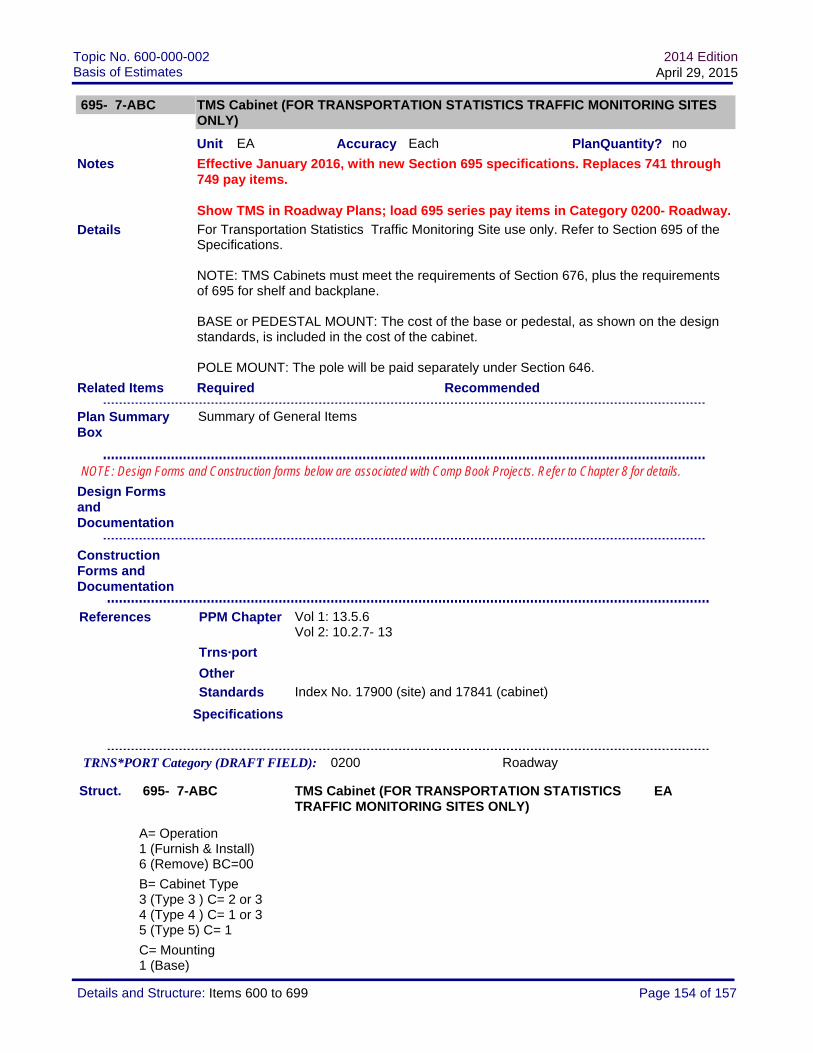
Topic No. 600-000-002Basis of Estimates
2014 EditionApril 29, 2015
695- 7-ABC TMS Cabinet (FOR TRANSPORTATION STATISTICS TRAFFIC MONITORING SITES ONLY)
Unit EA Accuracy Each PlanQuantity? no
Effective January 2016, with new Section 695 specifications. Replaces 741 through 749 pay items.
Show TMS in Roadway Plans; load 695 series pay items in Category 0200- Roadway.
For Transportation Statistics Traffic Monitoring Site use only. Refer to Section 695 of the Specifications.
NOTE: TMS Cabinets must meet the requirements of Section 676, plus the requirements of 695 for shelf and backplane.
BASE or PEDESTAL MOUNT: The cost of the base or pedestal, as shown on the design standards, is included in the cost of the cabinet.
POLE MOUNT: The pole will be paid separately under Section 646.
Required Recommended
Standards Index No. 17900 (site) and 17841 (cabinet)
Specifications
Vol 1: 13.5.6Vol 2: 10.2.7- 13
Struct. 695- 7-ABC TMS Cabinet (FOR TRANSPORTATION STATISTICS TRAFFIC MONITORING SITES ONLY)
EA
A= Operation1 (Furnish & Install) 6 (Remove) BC=00
B= Cabinet Type3 (Type 3 ) C= 2 or 34 (Type 4 ) C= 1 or 35 (Type 5) C= 1
C= Mounting1 (Base)
Details
Related Items
Design Forms and Documentation
PPM Chapter
Notes
References
Trns·port
TRNS*PORT Category (DRAFT FIELD): 0200 Roadway
Other
Construction Forms and Documentation
Plan Summary Box
Summary of General Items
NOTE: Design Forms and Construction forms below are associated with Comp Book Projects. Refer to Chapter 8 for details.
Page 154 of 157Details and Structure: Items 600 to 699

Topic No. 600-000-002Basis of Estimates
2014 EditionApril 29, 2015
2 (Pedestal)3 (Pole)
Notes
The following items were open, as of the publication date. Refer to the Master Pay Item list for current items. Additional items may be opened upon request.
Item Description Unit TSP/Detail Valid Date Obsolete Date
0695 7132 TRAFFIC MONOTORING SITE CABINET, FURNISH & INSTALL, TYPE 3, PEDESTAL MOUNT
EA 1/1/2016
0695 7141 TRAFFIC MONOTORING SITE CABINET, FURNISH & INSTALL, TYPE 4, BASE MOUNT
EA 1/1/2016
0695 7600 TRAFFIC MONOTORING SITE CABINET, REMOVE EXISTING CABINET
EA 1/1/2016
Page 155 of 157Details and Structure: Items 600 to 699

Topic No. 600-000-002Basis of Estimates
2014 EditionApril 29, 2015
695- 8- AB TMS System Comminucations Modem (FOR TRANSPORTATION STATISTICS TRAFFIC MONITORING SITES ONLY)
Unit EA Accuracy Each PlanQuantity? no
Effective January 2016, with new Section 695 specifications. Replaces 741 through 749 pay items.
Show TMS in Roadway Plans; load 695 series pay items in Category 0200- Roadway.
For Transportation Statistics Traffic Monitoring Site use only. Refer to Section 695 of the Specifications.
Most projects will require modem with antenna. Contact the State Transportation Statistics Office for guidance/approval if modem "without antenna" is needed.
Required Recommended
Standards Index No. 17900 (site) and 17841 (cabinet)
Specifications
Vol 1: 13.5.6Vol 2: 10.2.7- 13
Struct. 695- 8- AB TMS System Comminucations Modem (FOR TRANSPORTATION STATISTICS TRAFFIC MONITORING SITES ONLY)
EA
A= Operation1 (Furnish & Install)
B= Type1 (Includes antenna) 0 (without antenna) requires approval
Notes
Details
Related Items
Design Forms and Documentation
PPM Chapter
Notes
References
Trns·port
TRNS*PORT Category (DRAFT FIELD): 0200 Roadway
The following items were open, as of the publication date. Refer to the Master Pay Item list for current items. Additional items may be opened upon request.
Other
Construction Forms and Documentation
Plan Summary Box
Summary of General Items
NOTE: Design Forms and Construction forms below are associated with Comp Book Projects. Refer to Chapter 8 for details.
Page 156 of 157Details and Structure: Items 600 to 699

Topic No. 600-000-002Basis of Estimates
2014 EditionApril 29, 2015
Item Description Unit TSP/Detail Valid Date Obsolete Date
0695 8 11 TRAFFIC MONITORING SITE COMMUNICATIONS MODEM FURNISH & INSTALL
EA 1/1/2016
Page 157 of 157Details and Structure: Items 600 to 699