Embed Size (px)
Citation preview

GetThoseGrades
Topic: Electricity Specification reference: 3.5
Marks available: 127 Time allowed (minutes): 148 Examination questions from AQA. Don’t forget your data sheet! Mark scheme begins on page 35
Q1.
The graph below shows the current–voltage (I–V) characteristics for a resistor and a
filament lamp.
(a) Explain, in terms of electron motion, why the I–V characteristic for the filament lamp
is a curve.
___________________________________________________________________
___________________________________________________________________
___________________________________________________________________
___________________________________________________________________
___________________________________________________________________
___________________________________________________________________
___________________________________________________________________
___________________________________________________________________
___________________________________________________________________
___________________________________________________________________
(4)
(b) Determine the resistance of the resistor.

GetThoseGrades
resistance = ____________________ Ω
(1)
(c) The resistor and the filament lamp are connected in series with a supply of variable emf and negligible internal resistance.
Determine the emf that produces a current of 0.18 A in the circuit.
emf = ____________________ V
(3)
(d) The resistor and filament lamp are now connected in parallel.
Determine the resistance of the parallel combination when the emf of the supply is adjusted to be 4.0 V.
resistance = ____________________ Ω
(3)
(e) The resistance of the filament lamp at its working temperature is 14 Ω.
The filament has a length of 0.36 m and a diameter of 32 µm.
Calculate the resistivity of the metal that is used for the filament when the lamp is at its working temperature.
Give an appropriate unit for your answer.
resistivity = ____________________ unit ___________
(3)
(Total 14 marks)
Q2. Lengths of copper and iron wire are joined together to form junctions J1 and J2. When J1
and J2 are at different temperatures an emf ε is generated between them. This emf is
measured using a microvoltmeter.

GetThoseGrades
Figure 1 shows J1 kept at 0 °C while J2 is heated in a sand bath to a temperature θ measured by a digital thermometer.
Figure 1
An experiment is carried out to determine how ε depends on θ.
The results of the experiment are shown in the table below and a graph of the data is shown in Figure 2.
θ / °C ε / μV
200 1336
226 1402
258 1450
298 1456
328 1423
362 1345
392 1241
Figure 2

GetThoseGrades
(a) Plot the points corresponding to θ = 258 °C and θ = 298 °C on Figure 2.
(1)
(b) Draw a suitable best fit line on Figure 2.
(1)
(c) Determine the maximum value of ε.
maximum value of ε = ____________________ μV
(1)
(d) The gradient G of the graph in Figure 2 is measured for values of θ between
220 °C and 380 °C. A graph of G against θ is plotted in Figure 3.
Figure 3

GetThoseGrades
The neutral temperature θn is the temperature corresponding to the maximum value
of ε. θn can be determined using either Figure 2 or Figure 3.
Explain why a more accurate result for θn may be obtained using Figure 3.
___________________________________________________________________
___________________________________________________________________
___________________________________________________________________
___________________________________________________________________
___________________________________________________________________
(1)
(e) It can be shown that G is given by
G = βθ + α
where α and β are constants.
Determine α.
GetThoseGrades
α = ____________________ μV °C−1
(2)
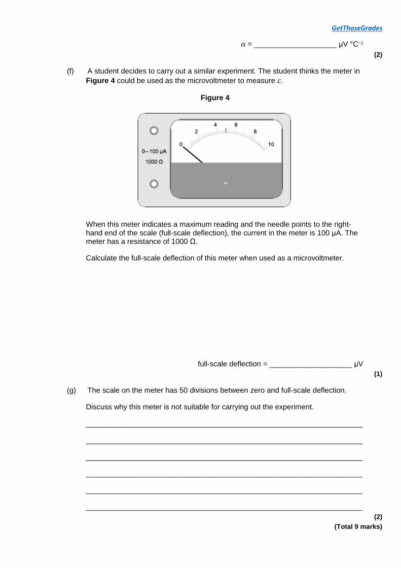
(f) A student decides to carry out a similar experiment. The student thinks the meter in
Figure 4 could be used as the microvoltmeter to measure ε.
Figure 4
When this meter indicates a maximum reading and the needle points to the right-hand end of the scale (full-scale deflection), the current in the meter is 100 μA. The meter has a resistance of 1000 Ω.
Calculate the full-scale deflection of this meter when used as a microvoltmeter.
full-scale deflection = ____________________ μV
(1)
(g) The scale on the meter has 50 divisions between zero and full-scale deflection.
Discuss why this meter is not suitable for carrying out the experiment.
___________________________________________________________________
___________________________________________________________________
___________________________________________________________________
___________________________________________________________________
___________________________________________________________________
___________________________________________________________________
(2)
(Total 9 marks)

GetThoseGrades
Q3. A wire probe is used to measure the rate of corrosion in a pipe carrying a corrosive liquid. The probe is made from the same metal as the pipe. Figure 1 shows the probe. The rate of corrosion of the wire in the probe is the same as in the pipe.
Figure 1
(a) The wire in an unused probe has a resistance of 0.070 Ω and a length of 0.50 m.
Calculate the diameter of the wire.
resistivity of metal in the wire = 9.7 × 10⁻⁸ Ω m
diameter = ____________________ m
(3)
(b) In order to measure the resistance of a used working probe, it is connected in the circuit shown in Figure 2.
Figure 2

GetThoseGrades
When R3 is adjusted to a particular value the current in the cell is 0.66 A.
Calculate the total resistance of the circuit. You may assume that the cell has a negligible internal resistance.
resistance = ____________________ Ω
(1)
(c) The resistance of R2 is 22 Ω and the resistance of R3 is 1.2 Ω.
Calculate the current in R3.
current = ____________________ A
(1)
(d) Calculate the resistance of the probe when the resistance of R1 is 2.4 Ω.
resistance = ____________________ Ω
(3)
(e) Calculate the percentage change in the diameter of the probe when its resistance

GetThoseGrades
increases by 1.6 %.
percentage change = ____________________ %
(2)
(f) A voltmeter is connected between points A and B in the circuit and R3 stays at 1.2 Ω.
Explain, without calculation, why the reading on the voltmeter does not change when the cell in the circuit is replaced with another cell of the same emf but a significant internal resistance.
___________________________________________________________________
___________________________________________________________________
___________________________________________________________________
___________________________________________________________________
___________________________________________________________________
(2)
(Total 12 marks)
Q4.
(a) The graph shows the current–voltage (I–V) characteristic curve for a semiconductor
diode.
In order to produce this characteristic a student is given suitable equipment including an ammeter and a voltmeter.
(i) Draw a labelled circuit diagram of the apparatus that the student could use to obtain the part of the characteristic from O to A.

GetThoseGrades
(2)
(ii) Describe how the student could use the circuit in part (a)(i) to obtain sufficient measurements to draw the part of the characteristic from O to A. Your account should include:
• details of how different readings of I and V are obtained
• a consideration of safety precautions when using the diode • a discussion of the range and number of measurements that need to be
taken • a discussion of the advantages of using a data logger to obtain the
measurements.
The quality of your written communication will be assessed in your answer.
(6)
(iii) Suggest how the circuit you drew in part (a)(i) could be modified to obtain the characteristic from O to B.
______________________________________________________________
______________________________________________________________
______________________________________________________________
______________________________________________________________
(1)
(b) The student wants to find out how the resistance of the diode changes between O and A.
(i) Describe how the student could use the characteristic to determine how the resistance varies as the potential difference (pd) between O and A increases.
______________________________________________________________
______________________________________________________________
______________________________________________________________
______________________________________________________________
(2)
(ii) State how you would expect the resistance of the diode to vary as the pd increases.
______________________________________________________________
______________________________________________________________
(1)
(Total 12 marks)
Q5. This question is about an experiment to determine the internal resistance of a power supply.
A student is given the circuit and the four resistors of known resistance shown in Figure 1.

GetThoseGrades
Figure 1
The student can change the external resistance R of the circuit between terminals X and
Y. This is done by connecting different combinations of two resistors in series or in parallel between X and Y.
This method can produce 12 different values for R.
(a) Calculate the largest value of R that the student can obtain using two resistors.
largest value of R = ____________________________ Ω
(1)
(b) Calculate the smallest value of R that the student can obtain using two resistors.
smallest value of R = ____________________________ Ω
(2)
(c) With switch S closed (in the on position) and no resistors connected between X and
Y the voltmeter reading V is 1.62 V.
The student concludes that this voltmeter reading equals the emf ε of the power
supply.
State why the student’s conclusion that ε = 1.62 V was correct.
___________________________________________________________________
___________________________________________________________________
___________________________________________________________________
(1)
(d) Figure 2 shows one particular combination and arrangement of two resistors that the student could use.
Figure 2

GetThoseGrades
When S is closed the voltmeter reading V is 1.14 V.
Explain why V is less than 1.62 V when S is closed.
___________________________________________________________________
___________________________________________________________________
___________________________________________________________________
(1)
(e) It can be shown that
where r is the internal resistance of the power supply.
Determine (ε – V ) and for this circuit using the data given in part (d).
(ε – V) = ____________________________ V
= ____________________________ V Ω–1
(1)
(f) The student obtains values of V for five further different values of R.
These data were used to produce the graph of (ε – V) against in Figure 3.
Plot the point you determined in part (e) on Figure 3 and add a suitable best-fit line.
(1)
(g) Use Figure 3 to determine r.

GetThoseGrades
r = ____________________________ Ω
(2)
Figure 3
(h) Figure 4 shows a different method for varying the resistance R described in part
(a).
Figure 4

GetThoseGrades
The four resistors are connected in a loop with sockets A, B, C and D at each junction. Two leads are used to connect the resistor loop to X and Y.
Discuss whether this method is an improvement over the method described in part (a). In your answer, you should refer to the number of different values that can be
obtained for R.
___________________________________________________________________
___________________________________________________________________
___________________________________________________________________
___________________________________________________________________
___________________________________________________________________
___________________________________________________________________
(2)
(Total 11 marks)
Q6. Figure 1 shows a circuit that includes an oscilloscope used to find the internal resistance
r of a battery.
Figure 1

GetThoseGrades
Figure 2 represents the screen of the oscilloscope. With switches S1 and S2 open, a bright spot is seen on the screen at P.
Figure 2
The vertical sensitivity of the oscilloscope is set at 2.0 V per division.
(a) Explain why the oscilloscope shows a bright spot rather than a horizontal line.
___________________________________________________________________
___________________________________________________________________
(1)
(b) When switch S1 is closed, the spot moves to R.
(i) State the electrical property of the battery represented by the deflection PR.

GetThoseGrades
______________________________________________________________
______________________________________________________________
(1)
(ii) Determine the value of the electrical quantity represented by the deflection PR.
electrical quantity = ____________________
(1)
(c) With switch S1 kept closed, switch S2 is also closed. The spot moves to Q.
Explain why the spot moves from R to Q.
___________________________________________________________________
___________________________________________________________________
___________________________________________________________________
___________________________________________________________________
___________________________________________________________________
(3)
(d) Calculate the current in the battery when both switches are closed.
current = ____________________ A
(2)
(e) Calculate the internal resistance of the battery.
internal resistance = ____________________ Ω
(2)
(Total 10 marks)
Q7. State what is meant by a superconductor.
_______________________________________________________________________

GetThoseGrades
_______________________________________________________________________
(Total 1 mark)
Q8. The diagram shows an electrical circuit in a car. A voltmeter of very high resistance is used to measure the potential difference across the terminals of the battery.
(a) Define potential difference.
___________________________________________________________________
___________________________________________________________________
(1)
(b) Explain how and why the voltmeter reading changes when the switch is closed.
___________________________________________________________________
___________________________________________________________________
___________________________________________________________________
___________________________________________________________________
___________________________________________________________________
___________________________________________________________________
(3)
(Total 4 marks)
Q9. The diagram shows the circuit diagram for a two-slice electric toaster that is operated at a mains voltage of 230 V.

GetThoseGrades
The toaster has four identical heating elements and has two settings: normal and low. On the normal setting both sides of the bread are toasted. On the low setting, only one side of the bread is toasted. The setting is controlled by switches S1 and S2.
The table shows the position of each switch and the power for each setting.
Setting S1 S2 Power / W
Low closed open 400
Normal closed closed 800
(a) Calculate the current in S2 when the normal setting is selected.
current ____________________ A
(2)
(b) (i) Show that the resistance of one heating element is approximately 260 Ω when the toaster is operating at its working temperature.
(2)
(ii) Calculate the total resistance when the normal setting is selected.
resistance ____________________ Ω
(2)
(iii) Each heating element is made of nichrome wire of diameter 0.15 mm. The nichrome wire is wrapped around an insulating board.
Determine the length of nichrome wire needed to provide a resistance of 260 Ω.

GetThoseGrades
resistivity of nichrome at the working temperature = 1.1 × 10⁻⁶ Ω m
length of wire ____________________ m
(3)
(c) Explain why the resistivity of the nichrome wire changes with temperature.
___________________________________________________________________
___________________________________________________________________
___________________________________________________________________
___________________________________________________________________
___________________________________________________________________
(3)
(d) The nichrome wire has an equilibrium temperature of 174°C when the toaster is operating.
Calculate the peak wavelength of the electromagnetic radiation emitted by the wire.
Give your answer to an appropriate number of significant figures.
peak wavelength ____________________ m
(3)
(Total 15 marks)
Q10. An engineer wants to use solar cells to provide energy for a filament lamp in a road sign.
The engineer first investigates the emf and internal resistance of a solar cell under typical operating conditions.
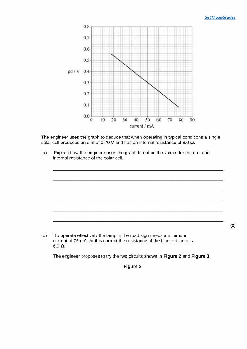
The engineer determines how the potential difference across the solar cell varies with current. The results are shown in the graph in Figure 1.
Figure 1
GetThoseGrades
The engineer uses the graph to deduce that when operating in typical conditions a single solar cell produces an emf of 0.70 V and has an internal resistance of 8.0 Ω.
(a) Explain how the engineer uses the graph to obtain the values for the emf and internal resistance of the solar cell.
___________________________________________________________________
___________________________________________________________________
___________________________________________________________________
___________________________________________________________________
___________________________________________________________________
___________________________________________________________________
(2)
(b) To operate effectively the lamp in the road sign needs a minimum current of 75 mA. At this current the resistance of the filament lamp is 6.0 Ω.
The engineer proposes to try the two circuits shown in Figure 2 and Figure 3.
Figure 2

GetThoseGrades
Figure 3
Deduce, using calculations, whether the circuits in Figure 2 and Figure 3 are suitable for this application.
___________________________________________________________________
___________________________________________________________________
___________________________________________________________________
___________________________________________________________________
(4)
(c) Solar cells convert solar energy to useful electrical energy in the road sign with an efficiency of 4.0%. The solar-cell supply used by the engineer has a total surface area of 32 cm 2.
Calculate the minimum intensity, in W m –2, of the sunlight needed to provide the minimum current of 75 mA to the road sign when it has a resistance of 6.0 Ω.

GetThoseGrades
intensity = ____________________ W m –2
(3)
(Total 9 marks)
Q11.
An electric oven is connected to a 230 V root mean square (rms) mains supply using a
cable of negligible resistance.
(a) (i) Calculate the peak-to-peak voltage of the mains supply.
peak-to-peak voltage = ____________________ V
(2)
(ii) The resistance of the heating element in the oven at its working temperature is 12 Ω.
Calculate the power dissipated by the heating element in the oven. Give your answer to an appropriate number of significant figures.
power = ____________________ W
(3)
(b) In practice the resistance of the cable connecting the oven to the mains supply is not negligible. Each of the two wires connecting the heating element to the mains electricity supply has a length of 3.15 m. Each metre of wire has a resistance of 0.0150 Ω.
(i) Explain why the rms voltage across the heating element in the oven will be
less than 230 V.
______________________________________________________________
______________________________________________________________
______________________________________________________________
______________________________________________________________
(2)
(ii) Calculate the rms voltage across the heating element in the oven when it is at its working temperature.

GetThoseGrades
rms voltage = ____________________ V
(3)
(iii) Calculate the average power wasted in the cable due to the heating effect of the electric current.
average power = ____________________ W
(2)
(iv) State two reasons why it is important that the cable has a low resistance.
1. ____________________________________________________________
______________________________________________________________
______________________________________________________________
2. ____________________________________________________________
______________________________________________________________
______________________________________________________________
(2)
(Total 14 marks)
Q12. A battery of negligible internal resistance and an emf of 12 V is connected in series with a heating element. The heating element has a resistance of 6.5 Ω when in operation.
What is the energy transferred by the heating element when operating for 5 minutes?
A 111 J
B 390 J
C 6650 J
D 23 400 J
(Total 1 mark)
Q13. Which statement about superconductors is correct?
A When a material becomes a superconductor, its resistivity is almost zero.
B The temperature at which a material becomes a superconductor is called the critical temperature.

GetThoseGrades
C When current passes through a superconductor the pd across it becomes a maximum.
D Copper is a superconductor at room temperature.
(Total 1 mark)
Q14.
A wire has a resistance R.
What is the resistance when both the length and radius of the wire are doubled?
A
B
C 2R
D 4R
(Total 1 mark)
Q15.
Three cells each have an emf ε = 1.5 V and an internal resistance r = 0.6 Ω.
Which combination of these cells will deliver a total emf of 1.5 V and a maximum current of 7.5 A?

GetThoseGrades
A
B
C
D
(Total 1 mark)
Q16. Which graph shows the variation of the resistance with temperature for an ntc thermistor?

GetThoseGrades
A
B
C
D
(Total 1 mark)
Q17. The figure shows a light dependent resistor (LDR) and fixed resistor R connected in series across a cell. The internal resistance of the cell is negligible.

GetThoseGrades
Which row shows how the readings on the ammeter and the voltmeter change when the light intensity incident on the LDR is increased?
Ammeter reading Voltmeter reading
A decreases increases
B decreases decreases
C increases increases
D increases decreases
(Total 1 mark)
Q18. In the circuit below, the potential difference across the light emitting diode (LED) is 1.8 V when it is emitting light.
The current in the circuit is 20 mA.
What is the value of the resistor R?
A 80 Ω
B 90 Ω
C 150 Ω

GetThoseGrades
D 160 Ω
(Total 1 mark)
Q19.
The combined resistance of n identical resistors connected in parallel is Rn.
Which statement correctly describes the variation of Rn as n increases?
A Rn decreases linearly as n increases
B Rn decreases non-linearly as n increases
C Rn increases linearly as n increases
D Rn increases non-linearly as n increases
(Total 1 mark)
Q20. The circuit shown is used to supply a variable potential difference (pd) to another circuit.
Which graph shows how the pd supplied V varies as the moving contact C is moved from
position P to position Q?

GetThoseGrades
A
B
C
D
(Total 1 mark)
Q21. In this resistor network, the emf of the supply is 12 V and it has negligible internal resistance.
What is the reading on a voltmeter connected between points X and Y?
A 0 V
B 1 V
C 3 V
D 4 V

GetThoseGrades
(Total 1 mark)
Q22. The current in the cell is 10 A as shown.
What is the current in the 2.0 Ω resistor?
A 0.35 A
B 2.86 A
C 3.50 A
D 7.14 A
(Total 1 mark)
Q23. The current in a wire is 20 mA.
How many electrons pass a point in the wire in 2 minutes?
A 2.5 × 10¹⁷
B 1.5 × 10¹⁹
C 2.5 × 10²⁰
D 1.5 × 10²²
(Total 1 mark)
Q24. A student investigates how the potential difference V across the terminals of a cell varies with the current I in the cell.

GetThoseGrades
Which graph correctly shows how V varies with I?
A
B
C
D
(Total 1 mark)
Q25. A cell C of negligible resistance and a switch are in series with a resistor R. The switch is
moved to the on (closed) position for a time t.
Which change reduces the amount of charge flowing through R in time t?

GetThoseGrades
A add an identical cell in parallel with C
B add an identical cell in series with C
C add a second resistor in series with R
D add a second resistor in parallel with R
(Total 1 mark)
Q26. A resistor and diode are connected in series with a variable power supply as shown in the diagram.
Which best shows the characteristic for the combination of the resistor and diode?
A

GetThoseGrades
B
C
D
(Total 1 mark)
Q27. A potential divider circuit consists of a battery connected across a thermistor and variable resistor in series.
Which of the following causes the potential difference (pd) across the thermistor to increase?
A increasing the temperature of the thermistor
B increasing the resistance of the variable resistor
C reducing the emf of the battery
D adding a resistor across the variable resistor
(Total 1 mark)
Q28. A battery is connected to a 10 Ω resistor and a switch in series. A voltmeter is connected across the battery. When the switch is open (off) the voltmeter reads 1.45 V. When the switch is closed the reading is 1.26 V.
What is the internal resistance of the battery?
A 0.66 Ω
B 0.76 Ω
C 1.3 Ω
D 1.5 Ω
(Total 1 mark)
Q29. The National Grid uses high-voltage transmission lines to carry electrical power around the UK. A particular transmission line delivers 800 MW of power at 132 kV to the user. It loses 1% of the transmitted power as heat.
What is the resistance of the transmission line?
A 0.2 Ω

GetThoseGrades
B 6 Ω
C 20 Ω
D 2000 Ω
(Total 1 mark)
Q30. The table shows the resistivity, length and cross-sectional area of wires P and Q.
resistivity length cross-sectional
area
wire P ρ L A
wire Q
L
The resistance of wire P is R.
What is the total resistance of the wires when they are connected in parallel?
A
B
C
D
(Total 1 mark)

GetThoseGrades
Mark schemes
Q1. (a) An increase in current / voltage leads to an increase in
temperature (more heat generated)
Ignore 'of particles' in first mark
Do not condone ‘particles’ in second mark
This causes an increase in the movement of the lattice/ions/atoms
And therefore an increase in the rate of collisions with
electrons
Allow more frequent collisions
So the resistance increases as shown by V / I changing/V
not proportional to I (on the graph)
Allow correct reference to gradient of I / V curve unless the answer suggests that this is the resistance or inverse of resistance.
Max 4
(b) 14.3 (Ω)
Allow range 14 to 15
but calculated answer must lie between 14 and 15 1
(c) Determination of pd across either filament or resistor from
graph
Pd across resistor can be calculated from resistance value in (b)
Eg V = 0.18 × 14.3 = 2.6
Determination of pd across the other component, and values added
Use of V = IR to give 3.4 (V)
Allow ecf if either value is wrong allow 2 max
Or
Clear attempt to determine total resistance and multiply by
0.18
Condone small rounding error
(Resistance of lamp at 0.18A = 4.4 Ω)
Total resistance = 18.7 Ω ecf from 2,2
3.4 V (ecf from 2.2)
Allow for small rounding errors (eg allow range 3.3 to 3.5) 3
(d) Determination of current through either filament or resistor from graph

GetThoseGrades
Allow calculation of resistor current using 4/(answer to 2.2)
Determination of current through the other component, and values added
(Current through resistor = 0.28 A
Current through filament = 0.36 A)
R = V/I = 4/ (0.28 + 0.36) = 6.25 (Ω)
If either value wrong allow 2 max
Condone small rounding errors.
Or
Calculation of filament resistance or statement of resistor resistance
Resistance of filament = 11.1 (Ω)
Calculation of other resistance and use of parallel formula
(allow ecf from part b)
Either resistance gets the first mark
6.2 -6.3 (Ω) 3
(e) Calculation of area, ignoring power of ten errors.
A = 8.0 × 10⁻¹⁰ m2
Correct resistivity 3.1 × 10⁻⁸
Allow ecf for A (for example use of d for r gives 3.2 × 10⁻¹¹ for A and 1.2 × 10⁻⁷ for answer)
Ω m
Some working must be shown for award of unit mark. 3
[14]
Q2. (a) 2 missing points plotted, each to nearest 1 mm (half a grid square); points
marked + or × or ; reject thick points, blobs or uncircled dots
1
(b) continuous smooth best fit line through all 7 points to 1 mm
allow mis-plotted points to be treated as anomalies; multiple lines or points of inflexion lose the mark
1

GetThoseGrades
(c) candidate’s value from Figure 2 ± ½ grid square
if multiple lines are drawn condone value if ± ½ grid square of all lines
1
(d) finding θN from Figure 3 is easy since the result is read off where G = 0 1
or
finding θN from Figure 2 is difficult since θ has a range of
values for which ε is a maximum 2
accept evidence that G = 0 used shown on Figure 3; physics
error about how Figure 3 used means no credit for any further valid comment about Figure 2
accept ‘curve is shallow at peak’ for 2 MAX 1
(e) method: correctly determines gradient of Figure 3 or uses gradient result with any point on line to determine (vertical) intercept
1
result in range 9.8 to 10.9 2
gradient values in the range −0.040 to −0.034 for 1 (minus
sign essential)
for 1 allow the substitution of at least one pair of correct
values of G and θ into G = βθ + α to obtain α using
simultaneous equations
condone 2sf ‘10’ for 2 2
(f) full scale pd = 100 × 1000 = 100000 or 105 μV
allow 100 mV or 0.1 V if μV deleted from answer line 1
(g) idea that resolution of the meter is not satisfactory 1
because the largest pd that will be measured is less than 1500 μV OR only uses 1.5% of the range OR
pd across meter at full-scale deflection ÷ divisions = =
2000 μV per division 2
condone use of ‘sensitivity’ or ‘precision’ for ‘resolution’; ignore ‘meter is not accurate’
allow ‘hard to tell different readings apart’
for 2 allow ce for incorrect 02.6
allow ‘unable to measure to nearest microvolt’
allow ‘resolution of scale should be 1 μV’ 2
[9]
Q3.

GetThoseGrades
(a) (use of R = ρl/A)
A = 9.7 × 10−8 × 0.50/0.070 1
A = 6.929 × 10⁻⁷ (m2) 1
diameter = √(6.929 × 10−7 × 4/π) = 9.4 × 10⁻⁴ (m)
CE for third mark if incorrect area 1
(b) R = 1.5/0.66 = 2.3(Ω) (2.27) 1
(c) (use of V = IR)
I = 1.5/(22 + 1.2) = 0.065(A) (0.0647) 1
(d) current in R1 = 0.66 − 0.0647 = 0.595 (A)
CE from 4.2/4.3 1
resistance of R1 and probe = 1.5/0.595 = 2.52 (Ω)
alternative method: 1/2.3 = 1/23.2 + 1/(Rprobe + 2.4) 1
resistance of probe = 2.52 − 2.4 = 0.12 (Ω)
correct rearrangement
range 0.1 – 0.15
accept 1 sig. fig. for final answer 1
(e) cross-sectional area must decrease OR R α 1/A
indicated by downward arrow or negative sign which can be seen on answer line
1
area decreases by 1.6% hence diameter must decrease by 0.8%
accept 1% 1
(f) ANY TWO FROM
correct reference to lost volts OR terminal pd OR reduced current
reference to resistors not changing OR resistors constant ratio
reference to voltmeter having high/infinite resistance (so not affecting circuit)
reference to pd between AB being (very) small (due to
closeness of resistance ratios in each arm)
voltmeter (may not be) sensitive enough 1
1
[12]
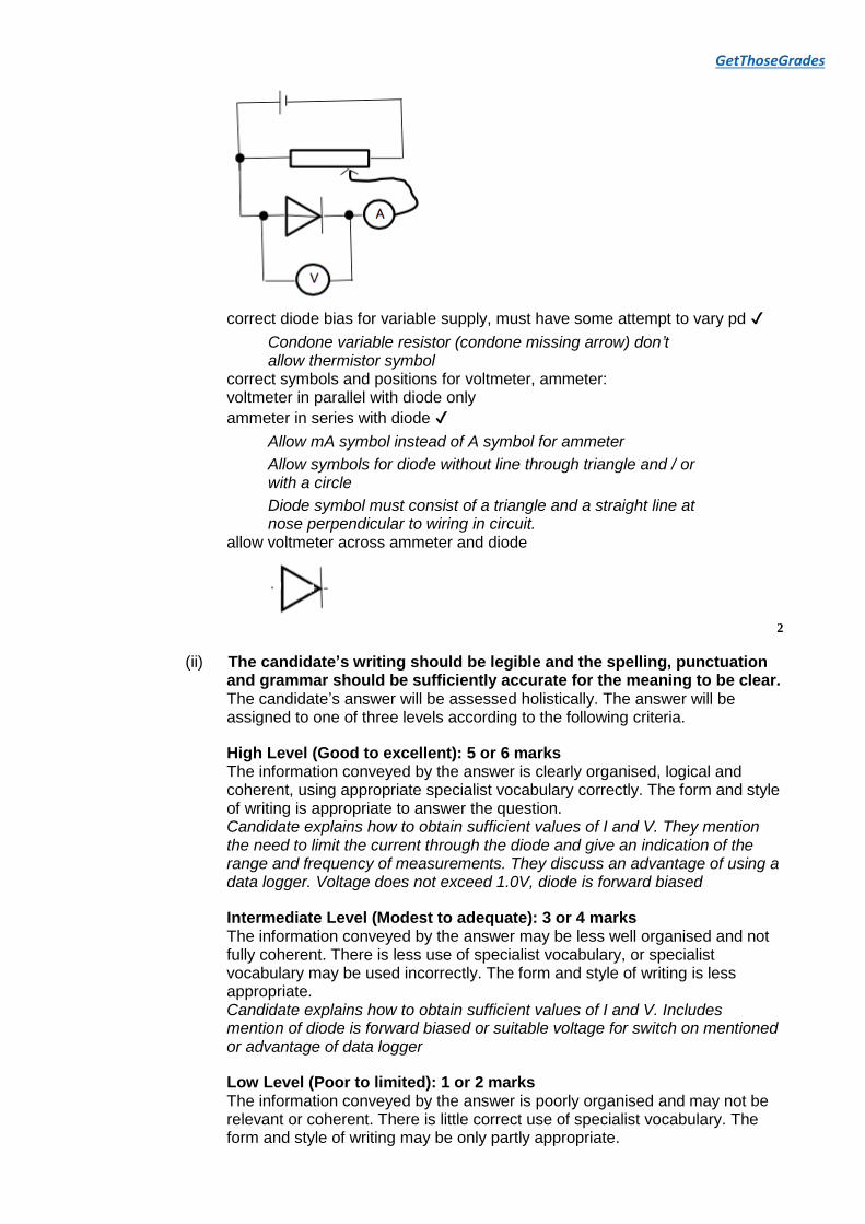
Q4. (a) (i)
GetThoseGrades
correct diode bias for variable supply, must have some attempt to vary pd
Condone variable resistor (condone missing arrow) don’t allow thermistor symbol
correct symbols and positions for voltmeter, ammeter: voltmeter in parallel with diode only
ammeter in series with diode
Allow mA symbol instead of A symbol for ammeter
Allow symbols for diode without line through triangle and / or with a circle
Diode symbol must consist of a triangle and a straight line at nose perpendicular to wiring in circuit.
allow voltmeter across ammeter and diode
2
(ii) The candidate’s writing should be legible and the spelling, punctuation and grammar should be sufficiently accurate for the meaning to be clear. The candidate’s answer will be assessed holistically. The answer will be assigned to one of three levels according to the following criteria.
High Level (Good to excellent): 5 or 6 marks The information conveyed by the answer is clearly organised, logical and coherent, using appropriate specialist vocabulary correctly. The form and style of writing is appropriate to answer the question. Candidate explains how to obtain sufficient values of I and V. They mention the need to limit the current through the diode and give an indication of the range and frequency of measurements. They discuss an advantage of using a data logger. Voltage does not exceed 1.0V, diode is forward biased
Intermediate Level (Modest to adequate): 3 or 4 marks The information conveyed by the answer may be less well organised and not fully coherent. There is less use of specialist vocabulary, or specialist vocabulary may be used incorrectly. The form and style of writing is less appropriate. Candidate explains how to obtain sufficient values of I and V. Includes mention of diode is forward biased or suitable voltage for switch on mentioned or advantage of data logger
Low Level (Poor to limited): 1 or 2 marks The information conveyed by the answer is poorly organised and may not be relevant or coherent. There is little correct use of specialist vocabulary. The form and style of writing may be only partly appropriate.

GetThoseGrades
vary pd obtain several readings of I and V or an advantage of using data logger or forward biased low level safety may include switch off / avoid overheating type arguments / don't touch
The explanation expected in a competent answer should include a coherent selection of the following points concerning the physical principles involved and their consequences in this case. means of controlling pd across diode indication of range and frequency of measurement mention of limiting current to avoid damage to diode a consideration of the advantages of a datalogger e.g. many readings, computer display of results use of potential divider instead of series resistor
All signs of quality that could lift mark
Lower band
vary pd obtain several readings of I and V
or an advantage of using data logger or low level safety and action to minimise risk
Middle band
vary pd and obtain several readings of I and V, at least 6 different values including an advantage of using data logger or mention of forward bias or mention of switch on voltage (0.6V) or safety
Top Band
Mention of how to vary pd (seen in viable circuit) obtain several readings of I and V, at least 6 different values (range given where maximum value of pd does not exceed 1.0V)
mention of limiting current through diode using protective resistor
consider advantage of data logger
mention forward bias
must include potentiometer for 6 marks
must have voltage as independent, no current led arguments in Top band
Data logger advantages:
Not more accurate
Not removes human error 6
(iii) reverse connections to the power supply / battery / cell / reverse diode
not switch wires around (need clear link to reversing connections at supply's terminals)
1
(b) (i) divide V by I for a reading from graph or uses R = V ⁄ I for a reading from
graph
Treat gradient = as TO
repeat for different values of V and I
Must score 1st mark to achieve 2nd 2

GetThoseGrades
(ii) (Resistance) decreases
Or resistance starts off very high and then becomes much lower
1
[12]
Q5.
(a) 15(.0) (Ω)
Only acceptable answer
Must be on answer line or clearly identified as (largest)R
by R = 15 (.0) (Ω) seen.
Allow an answer just above (or below) the answer line in cases where a previous answer has been crossed out.
If not on the answer line, units must be stated. 1
(b) 1.4(1) (Ω)
Only selects 2.2 Ω and 3.9 Ω in parallel
Accept evidence from working or a clear labelled sketch of 2.2 Ω and 3.9 Ω in parallel
Possible allowed combinations include:
Accept 1.407 Ω but not >4 sf
Must be on answer line or clearly identified as (smallest)R
by R = 1.4 (1) (Ω) seen.
Allow an answer just above (or below) the answer line in cases where a previous answer has been crossed out.
Common wrong answer = 0.71 (Ω) is worth one mark with correct supporting working
2
(c) Any of the following statements:
Power supply is on open circuit (so current is zero)
OR
Voltmeter has a (very) large resistance (so current is zero)

GetThoseGrades
OR
No current (load) (so no lost volts)
OR
(Current is zero) so no lost volts
Accept ‘negligible’ current for zero current
Accept ‘very large’ resistance; don’t penalise ‘voltmeter has very large internal resistance’
Do not allow:
Resistance is zero
Only resistance is the internal resistance
No other component (this implies that the internal resistance is zero)
1
(d) (Current through power supply leads to)
lost volts (across the internal resistance)
OR
(Current through power supply leads to)
voltage drop across the internal resistance
OR
(Current through power supply leads to)
Some of the emf is used in the internal resistance
OR
Voltage is shared between the internal and external resistances
Allow correct ‘energy transfer in the internal resistance’ arguments
Must refer to a voltage across the internal resistance or r
except when the term “lost volts” is used.
Do not allow:
The current decreases 1
(e) ε – V = (1.62 – 1.14 =) 0.48(0) (V)
and
Both results required for ; accept 0.127 or 0.1267 for
Do not allow answers expressed in terms of unknown variables

GetThoseGrades
Answers must be on answer line or clearly identified as answer by using correct subject and equals sign
Allow an answer just above (or below) the answer line in cases where a previous answer has been crossed out.
1
(f) Point correctly plotted to nearest 1 mm (half a grid square)
and
continuous ruled best fit line for the 5 (originally printed)
points
Withhold mark if point is hidden or if best fit line is of variable thickness or has discontinuities.
Data point should be marked with a cross. Both × and + marks are acceptable.
Do not allow points plotted as dots / dots in circles
If point is wrongly calculated in Part 1.5 allow CE for an accurate plot of this but this should then be treated as anomalous when judging the best fit line.
The best fit line must intersect each of the 5 originally printed X symbols.
Allow no plot where ECF (even as algebraic equation) point won’t fit on the grid and student has stated that it can’t be plotted.
If no answer / no plottable answer in 1.5 but student chooses to plot a point then it must be the correct point only (0.13, 0.48)
1
(g) Gradient triangle for Figure 3; correct read-offs for points (±
1 mm) from triangle with the ε – V step at least 0.5 V
Allow seen or gradient triangle drawn with seen,
read-offs must be substituted into or
Condone one read-off error in four read-offs for gradient method
(common error: candidates miss non-origin on ordinate axis)
(common error: makes a power of 10 error on abscissa)
r in range 3.49 to 3.95 (Ω)
Any correct method other than gradient method (no read-off errors here) allow 1 mark
i.e. allow 1 mark for the accurate use of 1 point from their line
r must be quoted to a minimum of 2 significant figures
ecf for r (their gradient from their best fit line)
r must be supported by correct working 2
(h) The Figure 1 method is better because more R values are available

GetThoseGrades
6 values of R (possible) for method (seen) in Fig 4
Do not allow:
The 2nd method has a wider range
The 2nd method has a larger maximum resistance
The 2nd method has a smaller minimum resistance
The 2nd method only goes up to 8.2 Ω
(resistances available in Fig 4: 2.0 Ω, 3.2 Ω, 4.3 Ω, 4.6 Ω, 5.0 Ω, 5.3 Ω)
2
[11]
Q6.
(a) time base is (switched) off
TO for y-input switched off
not affected by x plates because these plates are not switched on
1
(b) (i) emf (of battery)
not just terminal pd
TO applied for non-emf statements
Allow explanation of emf 1
(ii) (emf = 3 × 2.0 =) 6.0 V
penalise 1 sf 1
(c) Because the pd across the y plates has decreased
there is a current (in the battery)
there is a pd / voltage across the internal resistance or there are (now) lost volts
terminal pd decreases or terminal pd now less than emf or IR = ε -Ir 3
(d) V= 2.5 × 2.0 = 5 V
or (use of V=IR) by I = their incorrect voltage ÷18
Must see I as subject or their working leading to answer line for use of
I=0.28(A) cao 2
(e) (use of ε = IR +Ir)
6.0 = 2.5 × 2.0 + 0.28× r
or correct rearrangement to make r subject
or sets R(T) = = 21.2 or 21.4 (ohms) with subject seen
or

GetThoseGrades
r = 3.4 to 3.6 Ω
Ecf for I and V 2
[10]
Q7. Resistance is zero at (or below) critical temperature
“Negligible resistance” is insufficient
[1]
Q8. (a) work done per unit charge
Allow V=W/Q if W and Q defined 1
(b) Voltmeter reading / terminal pd drops Battery has internal resistance pd occurs within battery / ’lost volts’ within battery / emf is shared between internal and external resistances
3
[4]
Q9. (a) Correct substitution into P=VI
1.74 (A) 2
(b) (i) Correct substitution into R=V/I or V2/P or P/I2
264 (Ω)
Allow correct use of parallel resistor equation 2
(ii) Use of 1/RT = 1/R1 + 1/R2 or R = V2/P 65 (66.1) (Ω)
2
(iii) A = π(1.5 × 10⁻⁴)2/4 or π(7.5 × 10⁻⁵)2 or 1.767 × 10⁻⁸ (m2)
Substitution into l=RA/ρ with their area
4.2 (4.18) (m)
2 marks for 17 (m), using of d instead of r 3
(c) Resistivity / resistance increases with increasing temperature (Lattice) ions vibrate with greater amplitude Rate of movement of charge carriers / electrons (along wire) reduced (for given pd)
ORA
Condone atoms for ions.
Accept “vibrate more”.
Accept more frequent collisions occur between electrons and ions owtte
3

GetThoseGrades
(d) 2.9 × 10⁻³/447 or 2.9 × 10⁻³/174 seen 6.5 (6.49) × 10−6 (m) Correct answer given to 2 sig fig
Condone use of 174 for T for C1 and B1 marks
Allow 3 sig fig answer if 2.90 × 10⁻³ used 3
[15]
Q10.
(a) emf is the intercept on the pd / y axis
gradient of the graph is –r / internal resistance is minus the gradient of the graph/modulus of gradient is r / absolute
value of gradient is r / magnitude of gradient is r 1
1
(b) figure 2 circuit supplies 50 mA
figure 3 circuit has emf of 1.4 V
and internal resistance of 12 Ω
hence current of 78 mA which is >75 mA
Can use different routes independently for fig 2 and fig 3
If candidates calculated current is not 50 mA or 75 mA allow CE for correct conclusion relating to 75 mA
Must explain which circuit is suitable. If their calculation shows neither circuit suitable must explain why both circuits not suitable
OR
calculate required pd is 0.45 V (0.075 × 6.0)
show pd for cell in fig 2 is 0.1 V
show pd across parallel cells in fig 3 is 0.4 V
show total pd in fig 3 is 0.5 V which is greater than 0.45 V
OR
calculate emf needed for 75 mA in fig 2 (1.05)
calculate emf needed in fig 3 (1.35)
comment on emf needed in fig 2 is larger than cell provides
comment on emf in fig 3 being close to what is required
from graph for current for current of 75 mA
from graph for current of ½ of 75 mA i.er. 37.5 mA
i.e. 0.1 V from single cell and 0.4 V from parallel cells 4
(c) useful power dissipated = (75 × 10–3)2 × 6 (= 0.03375 (W))
Condone use of 78 mA gives answer of 285 W
If used resistance of 18 Ω then lose first mark but CE to give answer of 791 W
input power (at the cells) = 0.03375/.04 = (W)

GetThoseGrades
solar power = 0.8437 /(32 × 10–4) = 260 (263.7 or 264) W m–2
CE from power calculation but not from % calculation
if incorrect % calculation at any stage only qualify for useful power mark
1
1
1
[9]
Q11.
(a) (i) 230 × √2 = 325 (V)
(2 × 325 =) 650 to 651 V
allow doubling their incorrect peak voltage (162.6 × 2) by use
of 2 as an attempt to find peak-to-peak for 1 mark but not just 2 × 230
2
(ii) (use of P = V2/R)
P = 2302/12
P = 4.4 × 10³ (W) cao
2 sig. figs. Incorrect answer must be supported by working
Allow their incorrect answer (a)(i)2 ÷ 12
Or 3252 ÷ 12 as a use of for 1 mark
Alternative
For first mark
I = and P=VI allowing their incorrect answer
(a)(i) or 325 as sub for V for 1 mark
Answers 8.8 kW (325V) and 35 kW (650V) 3
(b) (i) there is a pd / voltage across the cable
pd / voltage across cooker is 230 V minus this pd / voltage
2nd mark depends on 1st mark in all
The current is lower due to the resistance of cable / The
current is lower as circuit resistance increases
pd across oven is lower since V=I × Resistance of element
or
Resistance of the cable is in series with element
Voltage splits (in ratio ) across these resistances 2
(ii) resistance of cable = 2 × 3.15 × 0.0150 = 0.0945
Allow power 10 error here
Or
=228 V cao

GetThoseGrades
Allow their incorrect Rcable correctly substituted for 2nd
marking 3
(iii) 230 − their (b) (ii) or 19 (A) quoted for current or equivalent seen in equation
(230 / 12.0945)
(P =) 34.2 to 42.3(W) correct working
ecf as P = (230- (b)(ii))2 / their Rcable
2
(iv) minimise power loss / maximise efficiency of oven / ensure element gets as
hot as possible
avoid overheating / fires
not just to carry a large current / larger pd across element
Either order 2
[14]
Q12. C
[1]
Q13. B
[1]
Q14. B
[1]
Q15. D
[1]
Q16. C
[1]
Q17. D
[1]
Q18. C
[1]
GetThoseGrades
Q19. B
[1]
Q20. C
[1]
Q21. B
[1]
Q22. B
[1]
Q23. B
[1]
Q24. A
[1]
Q25. C
[1]
Q26. A
[1]
Q27. D
[1]
Q28. D
[1]
Q29. A
[1]