Embed Size (px)
Citation preview
Composites and
carbon fibers
Topic 2
Reading assignment
• Askeland and Phule, “The Science and Engineering of Materials”, 4th Edition, Ch. 16.
• Shakelford, “Introduction to Materials Science for Engineers”, 6th Edition, Ch. 14.
• Chung, “Composite Materials”, Ch. 2.
• Chung, “Carbon Fiber Composites”, Ch. 1, 2 and 3.
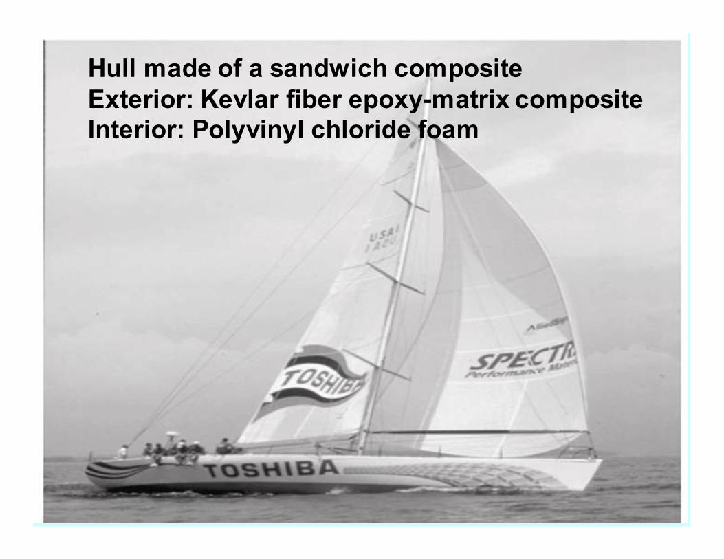
Hull made of a sandwich composite
Exterior: Kevlar fiber epoxy-matrix composite
Interior: Polyvinyl chloride foam
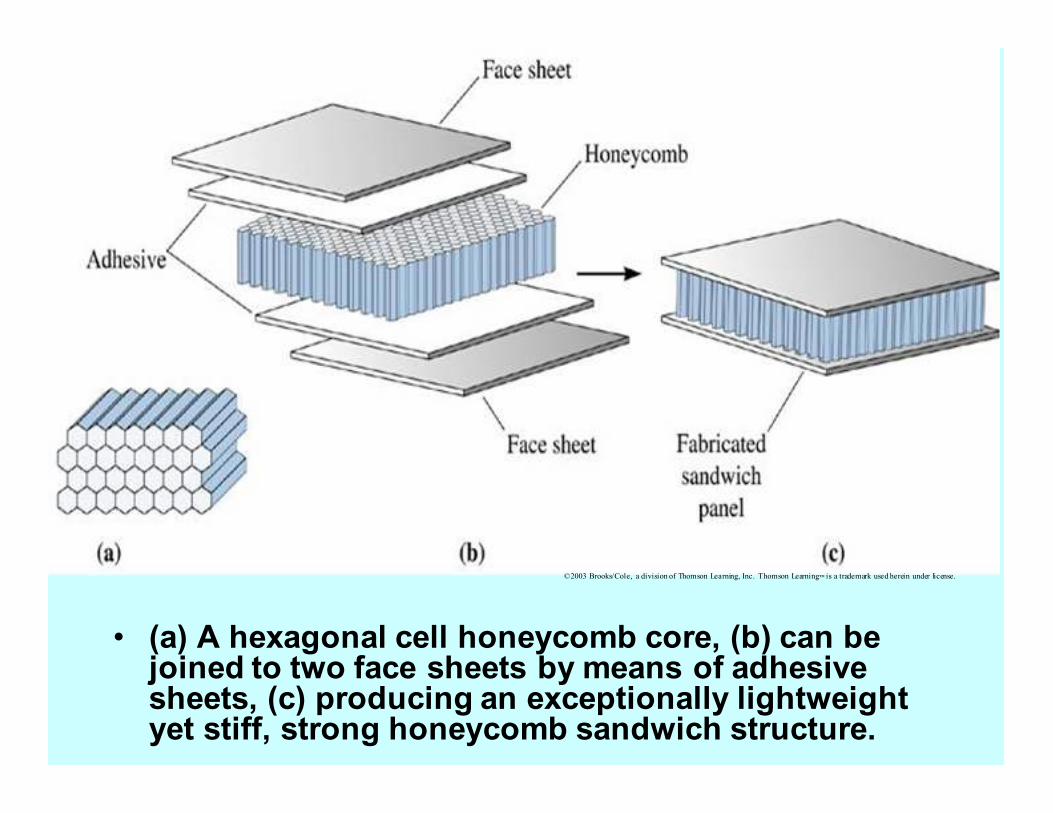
• (a) A hexagonal cell honeycomb core, (b) can be joined to two face sheets by means of adhesive sheets, (c) producing an exceptionally lightweight yet stiff, strong honeycomb sandwich structure.
©2003 Brooks/Cole, a division of Thomson Learning, Inc. Thomson Learning™ is a trademark used herein under license.
©2003 Brooks/Cole, a division of Thomson Learning, Inc. Thomson Learning™ is a trademark used herein under license.
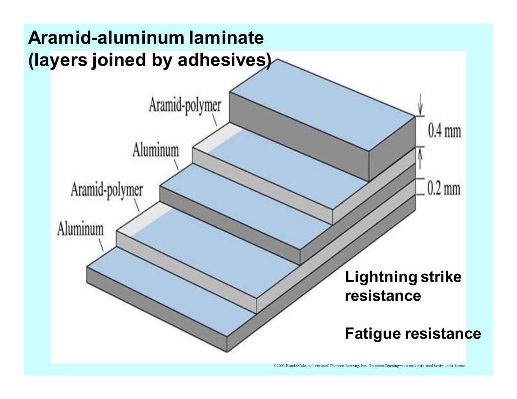
Aramid-aluminum laminate
(layers joined by adhesives)
Lightning strike
resistance
Fatigue resistance
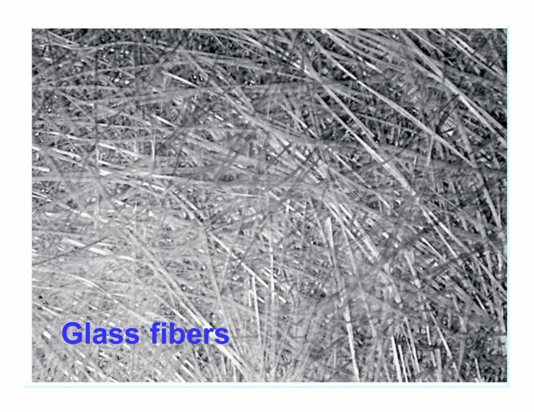
Glass fibers
©2003 Brooks/Cole, a division of Thomson Learning, Inc. Thomson Learning™ is a trademark used herein under license.
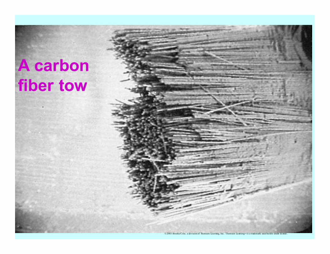
A carbon
fiber tow
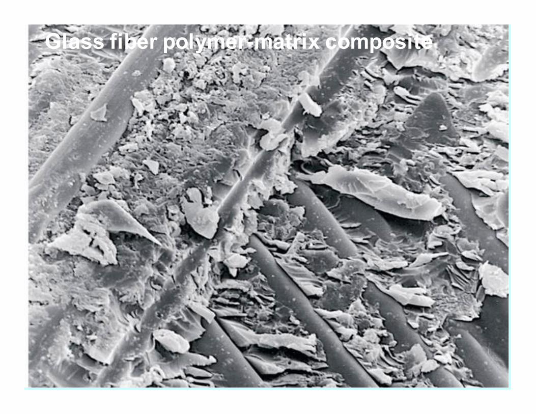
Glass fiber polymer-matrix composite
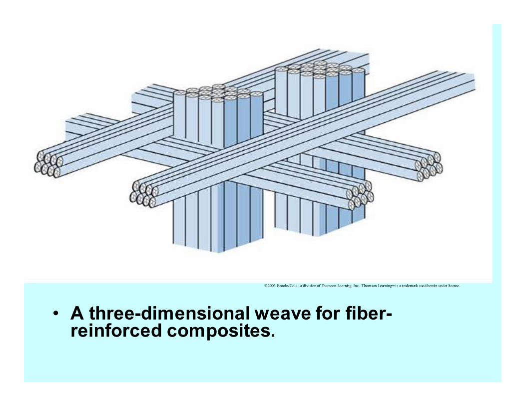
• A three-dimensional weave for fiber-reinforced composites.
©2003 Brooks/Cole, a division of Thomson Learning, Inc. Thomson Learning™ is a trademark used herein under license.

• (a) Tapes containing aligned fibers can be joined to produce a multi-layered different orientations to produce a quasi-isotropic composite. In this case, a 0°/+45°/90° composite is formed.
©2003 Brooks/Cole, a division of Thomson Learning, Inc. Thomson Learning™ is a trademark used herein under license.
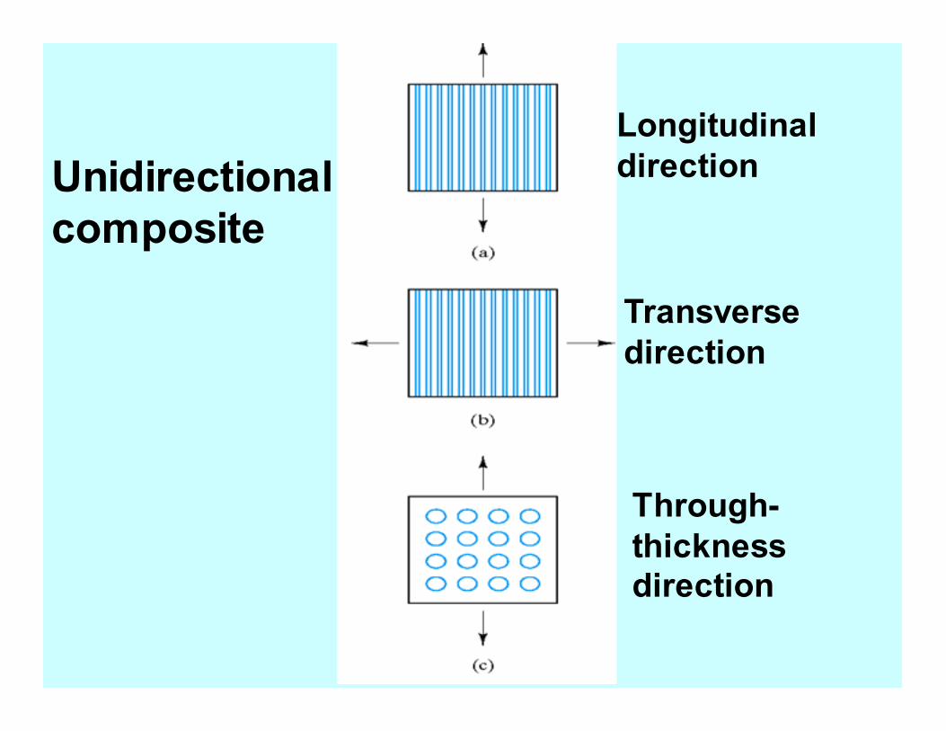
Longitudinal
direction
Transverse
direction
Through-
thickness
direction
Unidirectional
composite
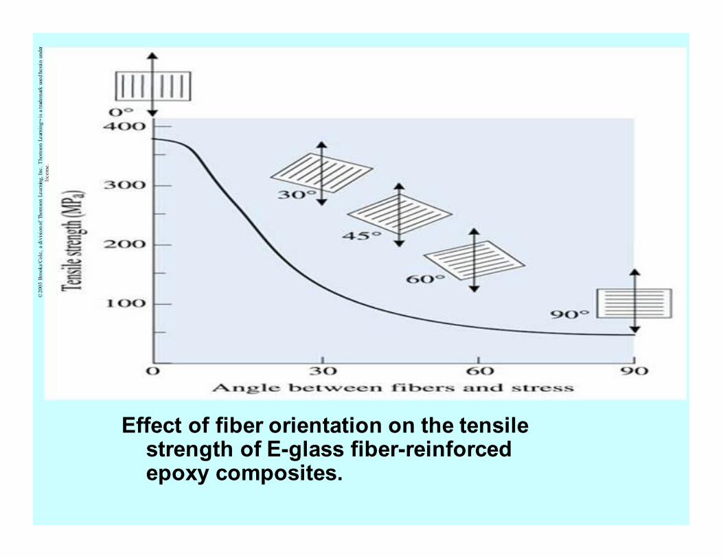
Effect of fiber orientation on the tensile strength of E-glass fiber-reinforced epoxy composites.
©2003 B
rooks/Cole, a division of Thomson Learning, Inc. Thomson Learning™ is a trademark used herein under
license.
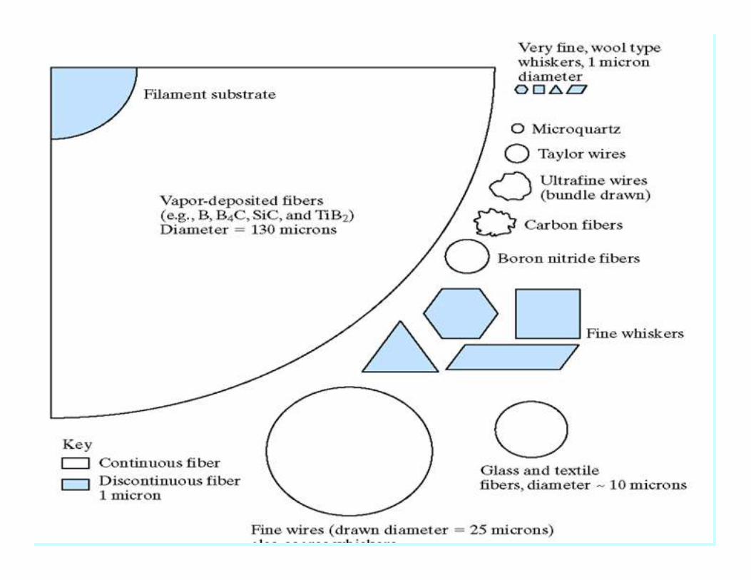
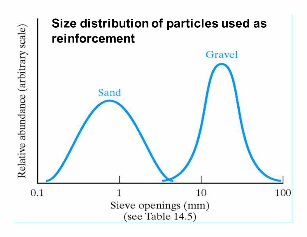
Size distribution of particles used as
reinforcement
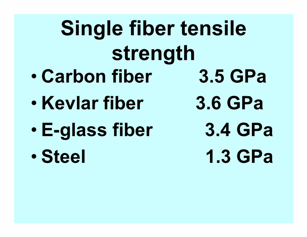
Single fiber tensile
strength •Carbon fiber 3.5 GPa
•Kevlar fiber 3.6 GPa
• E-glass fiber 3.4 GPa
• Steel 1.3 GPa
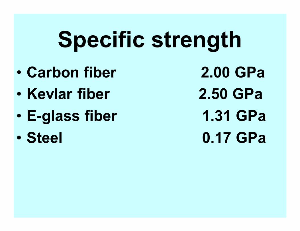
Specific strength
• Carbon fiber 2.00 GPa
• Kevlar fiber 2.50 GPa
• E-glass fiber 1.31 GPa
• Steel 0.17 GPa
Single fiber tensile
modulus • Carbon fiber 230 GPa
• Kevlar fiber 60 GPa
• E-glass fiber 22 GPa
• Steel 210 GPa
• Comparison of the specific strength and specific modulus of fibers versus metals and polymers.
©2003 B
rooks/Cole, a division of Thomson Learning, Inc. Thomson Learning™ is a trademark used herein under license.
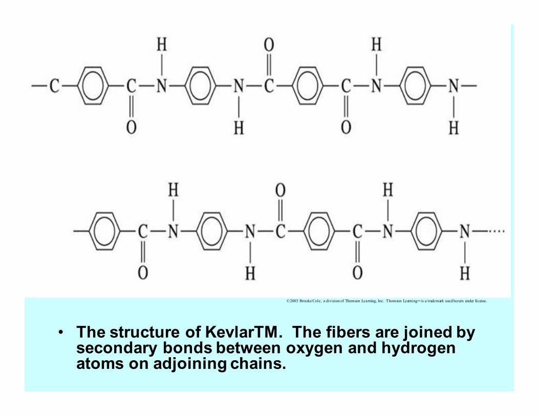
• The structure of KevlarTM. The fibers are joined by secondary bonds between oxygen and hydrogen atoms on adjoining chains.
©2003 Brooks/Cole, a division of Thomson Learning, Inc. Thomson Learning™ is a trademark used herein under license.
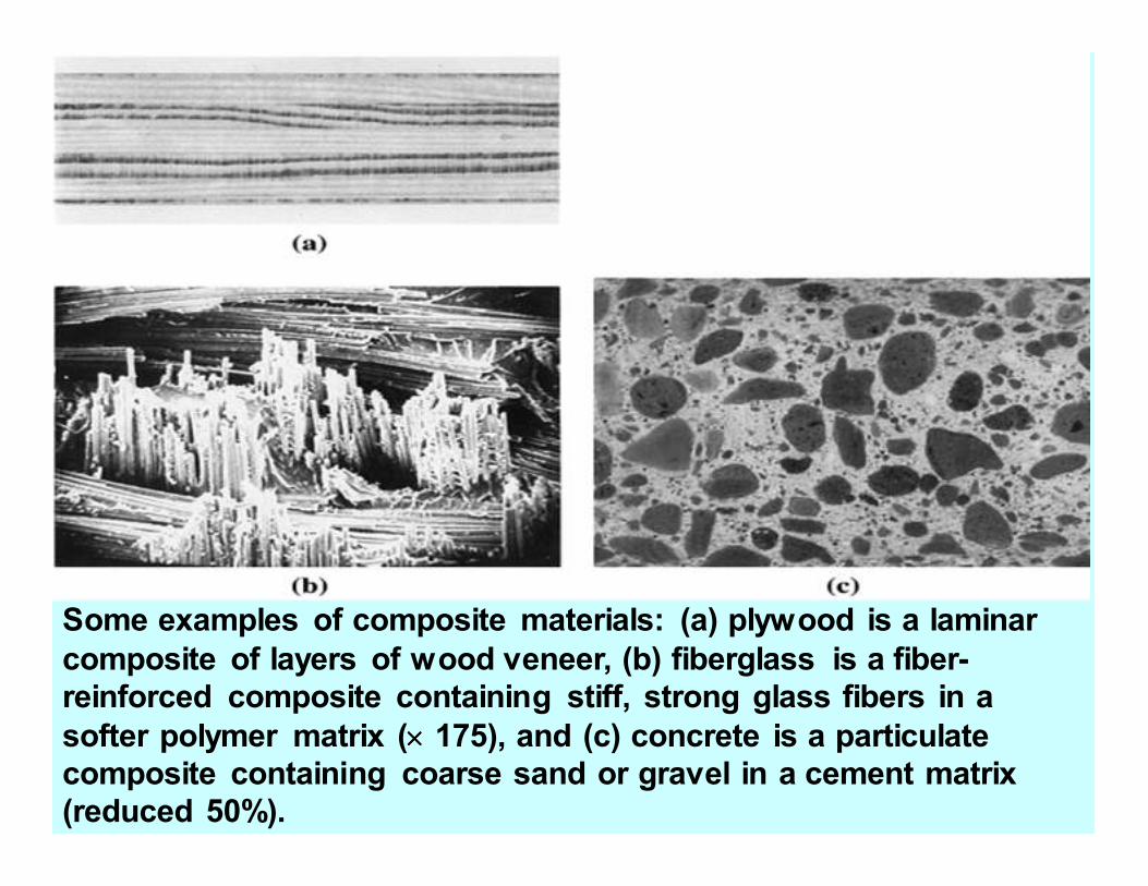
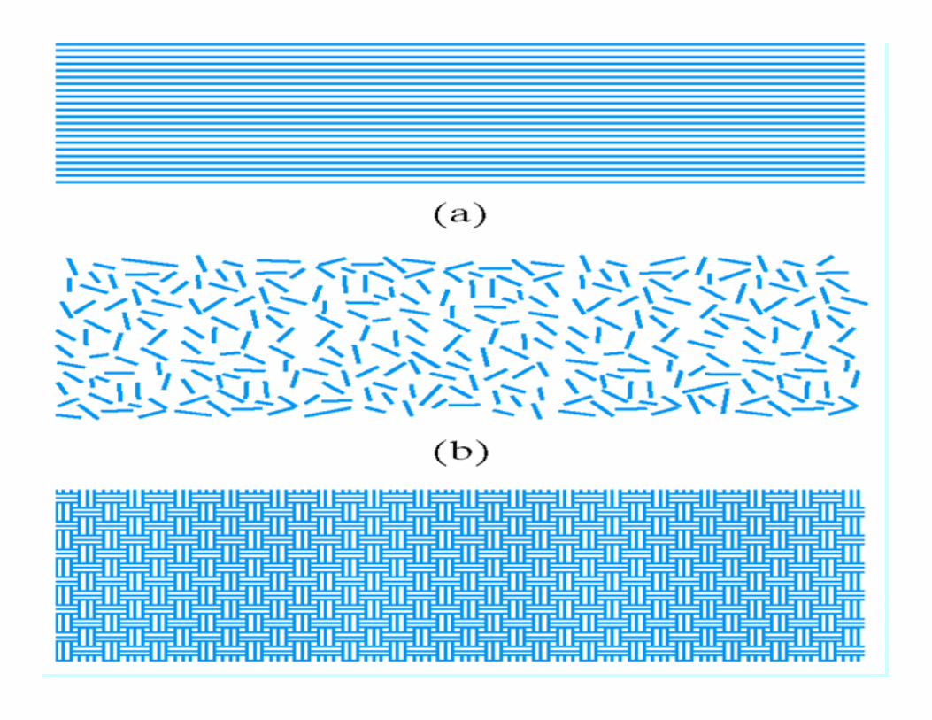
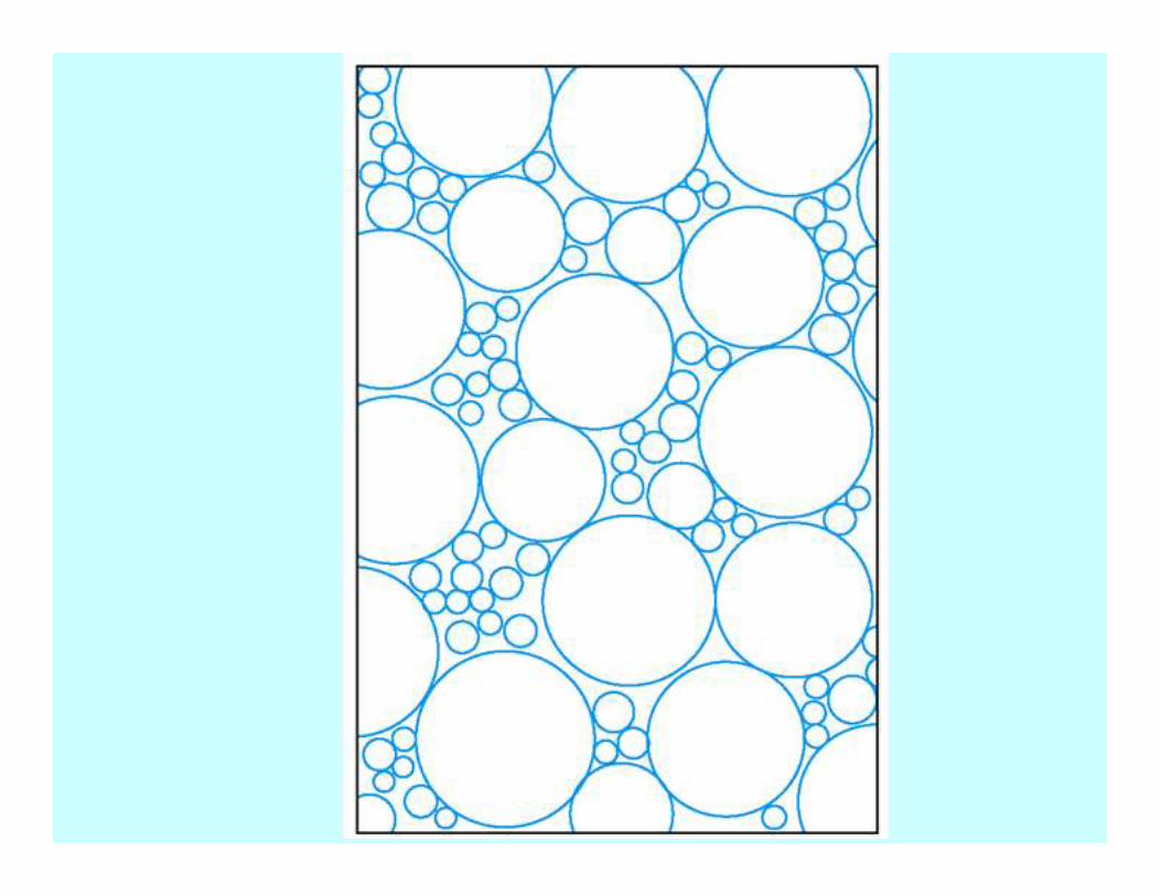
Some examples of composite materials: (a) plywood is a laminar
composite of layers of wood veneer, (b) fiberglass is a fiber-
reinforced composite containing stiff, strong glass fibers in a
softer polymer matrix (×××× 175), and (c) concrete is a particulate
composite containing coarse sand or gravel in a cement matrix
(reduced 50%).
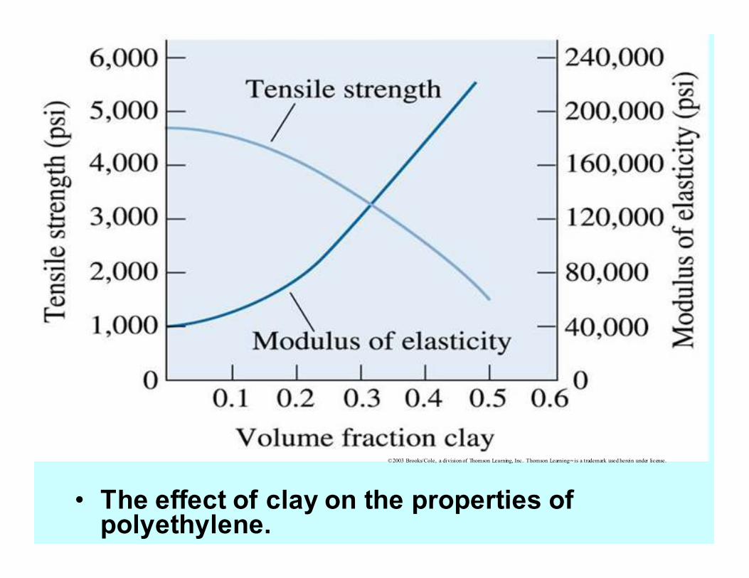
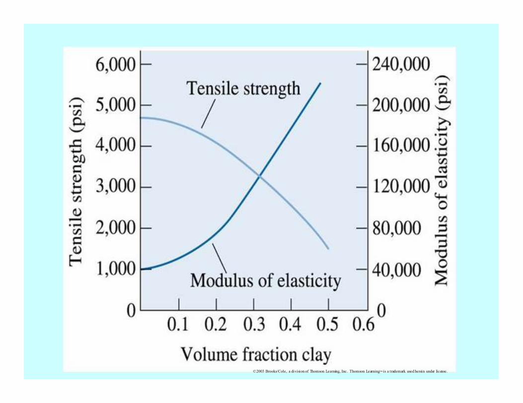
• The effect of clay on the properties of polyethylene.
©2003 Brooks/Cole, a division of Thomson Learning, Inc. Thomson Learning™ is a trademark used herein under license.
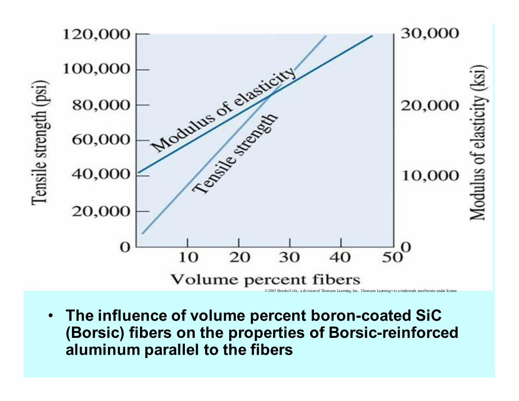
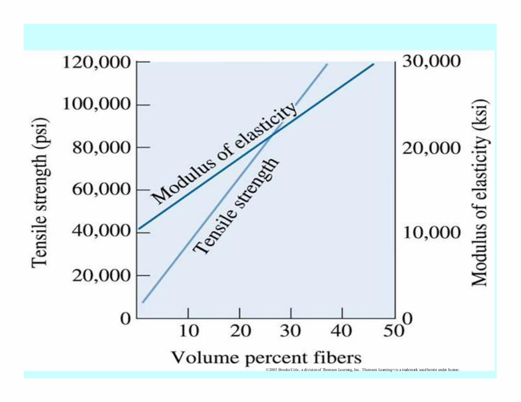
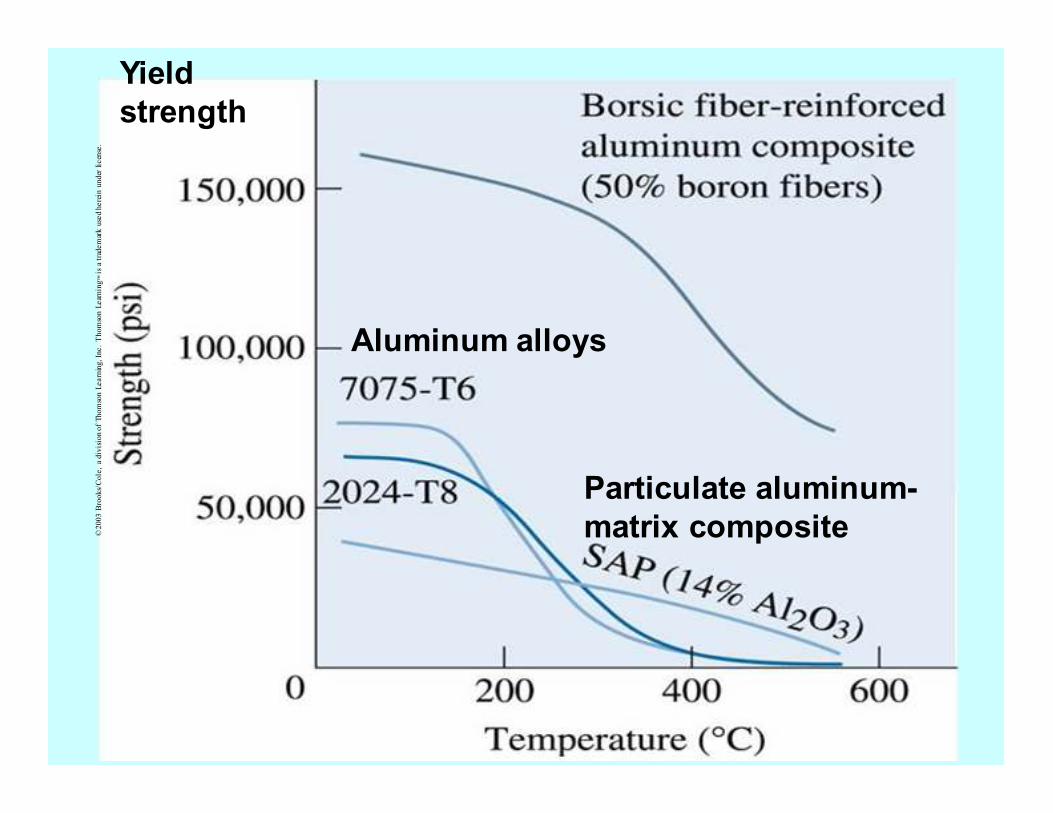
• The influence of volume percent boron-coated SiC (Borsic) fibers on the properties of Borsic-reinforced aluminum parallel to the fibers
©2003 Brooks/Cole, a division of Thomson Learning, Inc. Thomson Learning™ is a trademark used herein under license.
©2003 Brooks/Cole, a division of Thomson Learning, Inc. Thomson Learning™ is a trademark used herein under license.
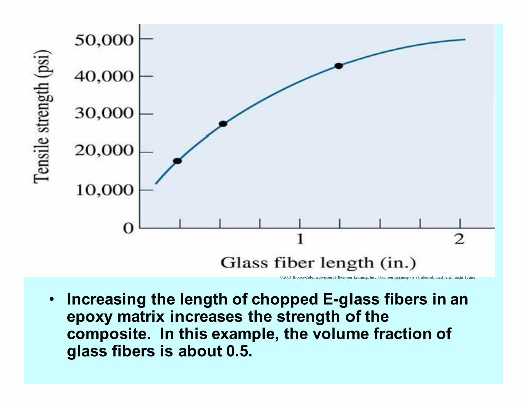
• Increasing the length of chopped E-glass fibers in an epoxy matrix increases the strength of the composite. In this example, the volume fraction of glass fibers is about 0.5.
©2003 Brooks/Cole, a division of Thomson Learning, Inc. Thomson Learning™ is a trademark used herein under license.
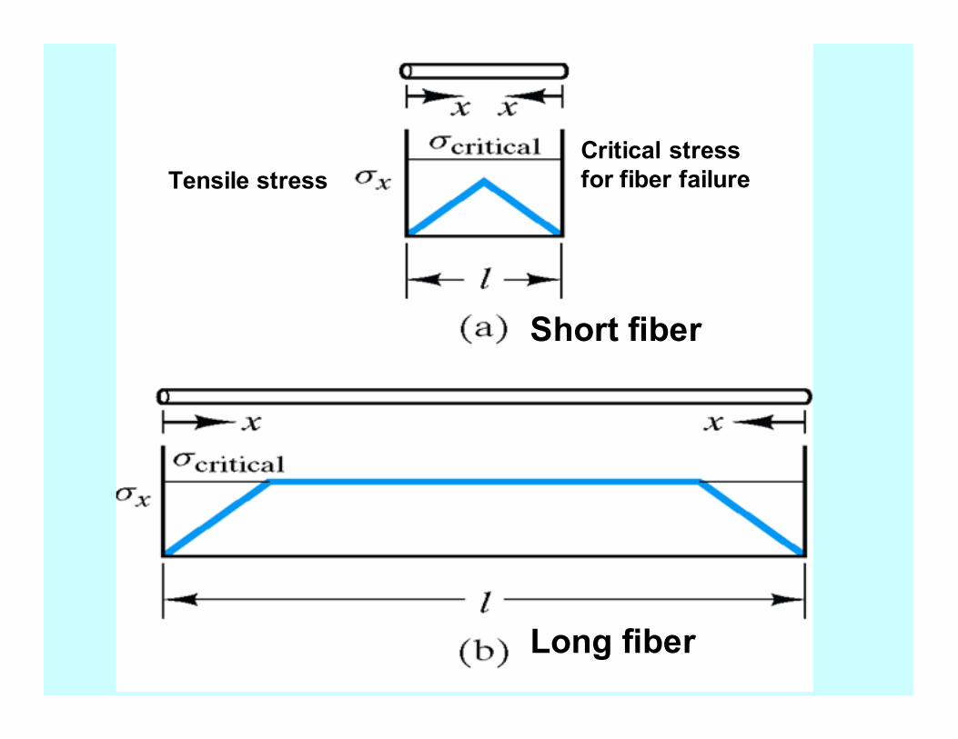
Critical stress
for fiber failure Tensile stress
Short fiber
Long fiber

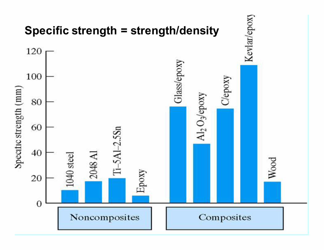
A comparison of the specific modulus and specific strength of several composite materials with those of metals and polymers.
©2003 Brooks/Cole, a division of Thomson Learning, Inc. Thomson Learning™ is a trademark used herein under license.
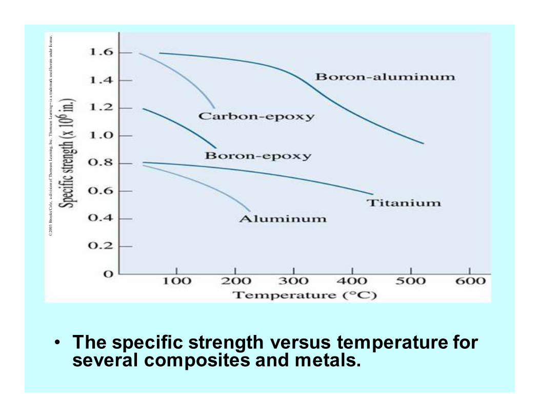
• The specific strength versus temperature for several composites and metals.
©2003 B
rooks/Cole, a division of Thomson Learning, Inc. Thomson Learning™ is a trademark used herein under license.
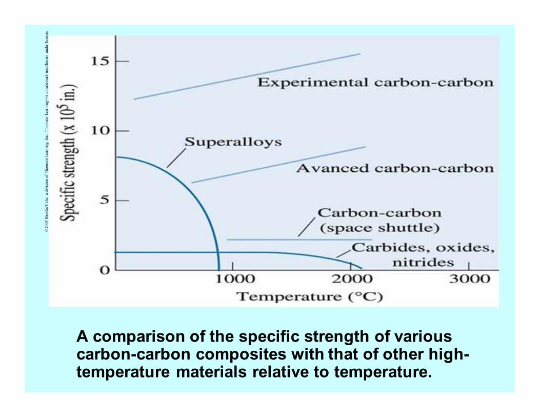
A comparison of the specific strength of various carbon-carbon composites with that of other high-temperature materials relative to temperature.
©2003 B
rooks/Cole, a division of Thomson Learning, Inc. Thomson Learning™ is a trademark used herein under license.
Methods of fabricating
polymer-matrix composites
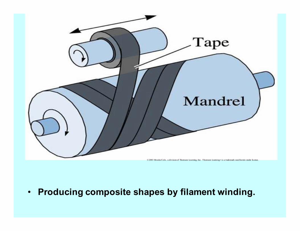
• Producing composite shapes by filament winding.
©2003 Brooks/Cole, a division of Thomson Learning, Inc. Thomson Learning™ is a trademark used herein under license.
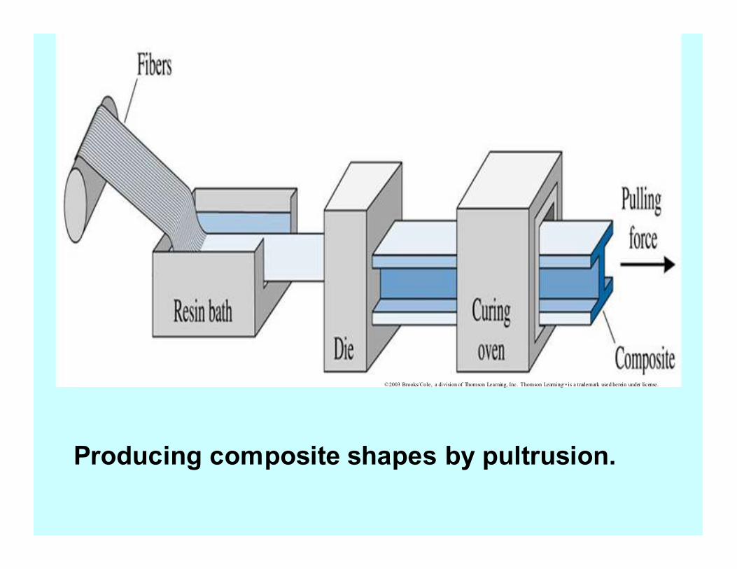
Producing composite shapes by pultrusion.
©2003 Brooks/Cole, a division of Thomson Learning, Inc. Thomson Learning™ is a trademark used herein under license.
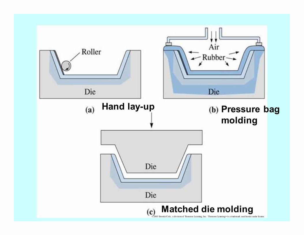
©2003 Brooks/Cole, a division of Thomson Learning, Inc. Thomson Learning™ is a trademark used herein under license.
Hand lay-up Pressure bag
molding
Matched die molding
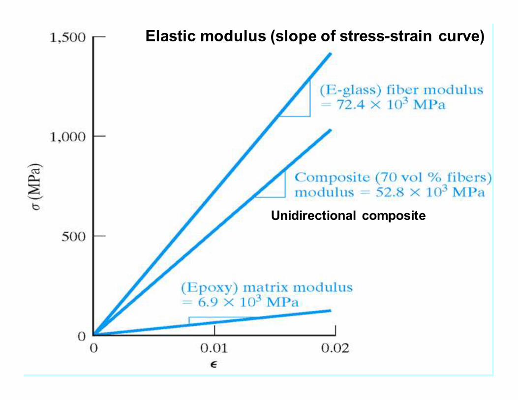
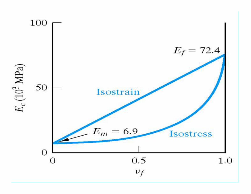
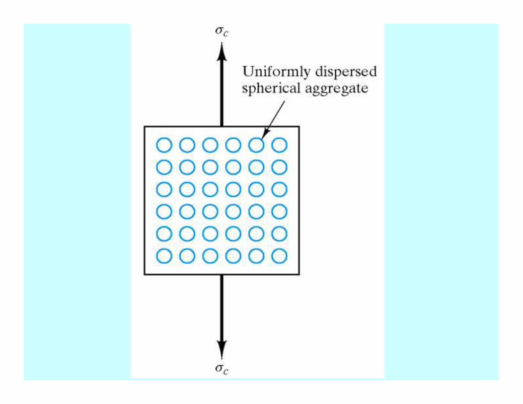
Elastic modulus (slope of stress-strain curve)
Unidirectional composite
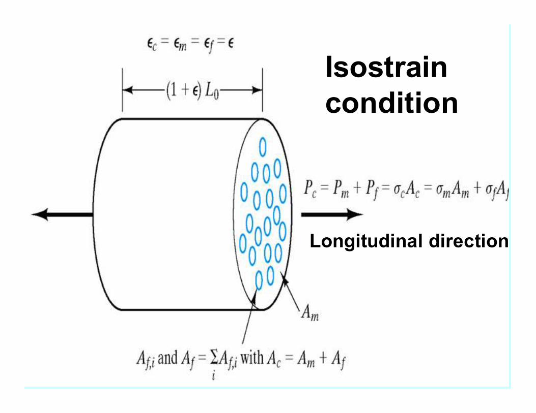
Isostrain
condition
Longitudinal direction
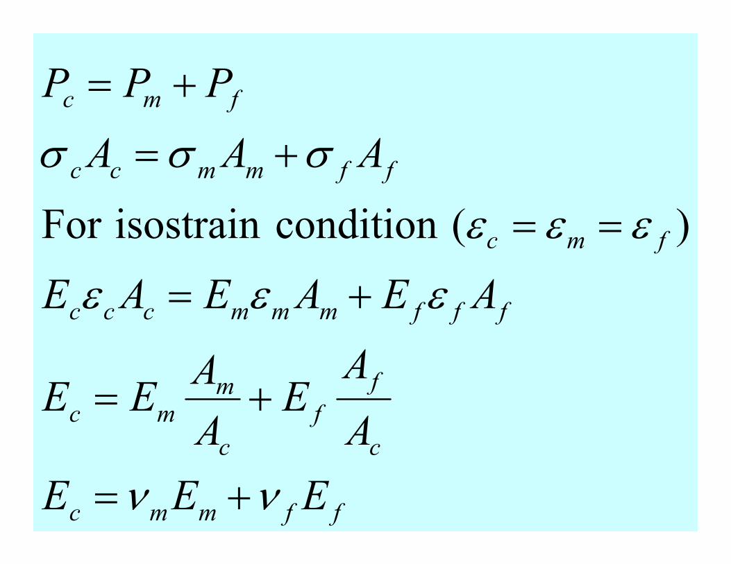
ffmmc
c
f
f
c
mmc
fffmmmccc
fmc
ffmmcc
fmc
EEE
A
AE
A
AEE
AEAEAE
AAA
PPP
νν
εεε
εεε
σσσ
+=
+=
+=
==
+=
+=
)(conditionisostrainFor
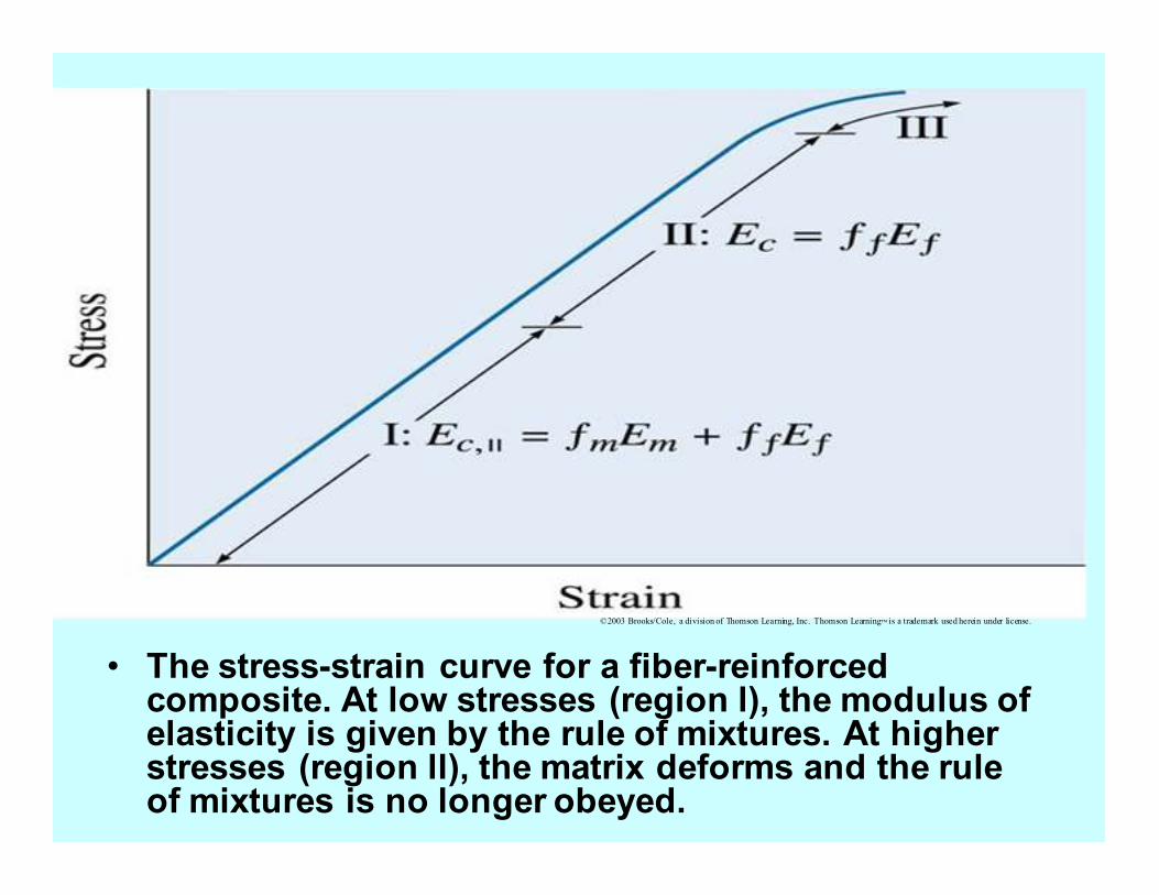
• The stress-strain curve for a fiber-reinforced composite. At low stresses (region l), the modulus of elasticity is given by the rule of mixtures. At higher stresses (region ll), the matrix deforms and the rule of mixtures is no longer obeyed.
©2003 Brooks/Cole, a division of Thomson Learning, Inc. Thomson Learning™ is a trademark used herein under license.
©2003 Brooks/Cole, a division of Thomson Learning, Inc. Thomson Learning™ is a trademark used herein under license.
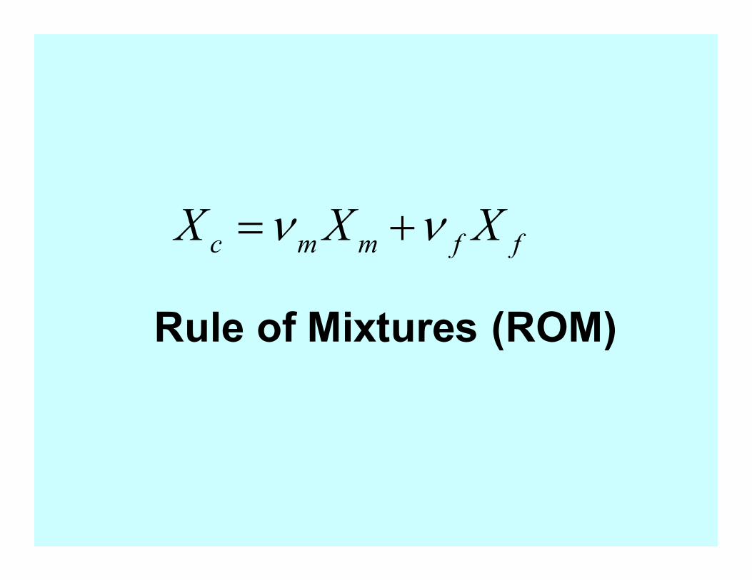
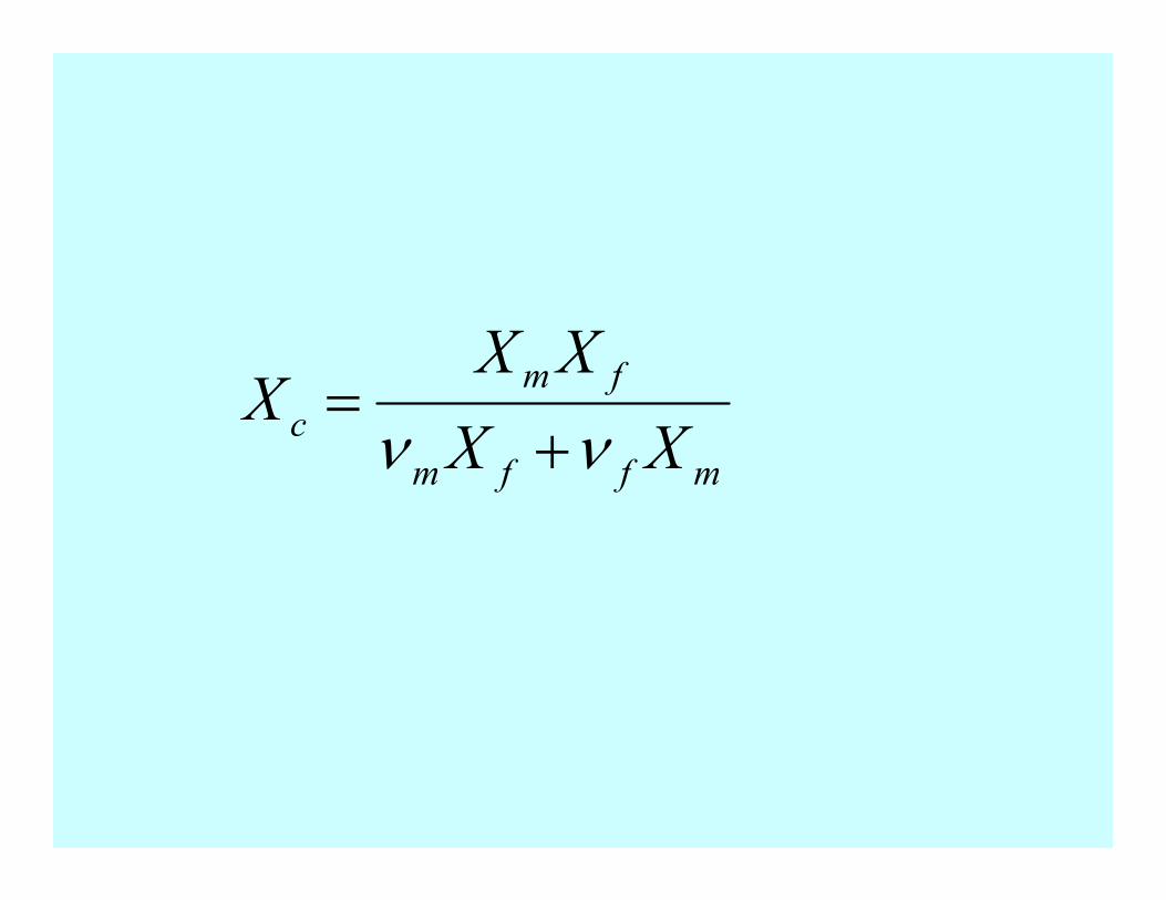
ffmmc XXX νν +=
Rule of Mixtures (ROM)
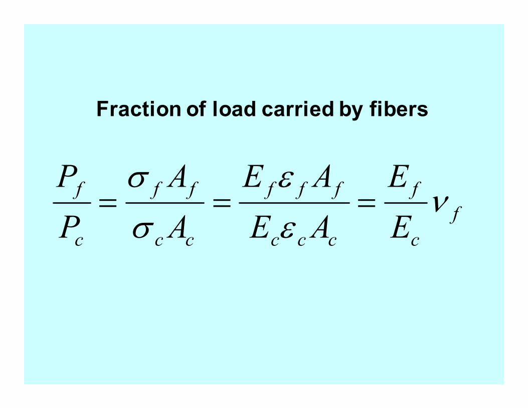
f
c
f
ccc
fff
cc
ff
c
f
E
E
AE
AE
A
A
P
Pν
ε
ε
σ
σ===
Fraction of load carried by fibers
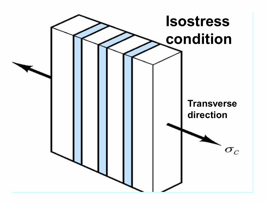
Isostress
condition
Transverse
direction
c
f
c
m
c
c
fmc
fmc
L
L
L
L
L
L
LLL
∆+
∆=
∆
∆+∆=∆
== σσσ
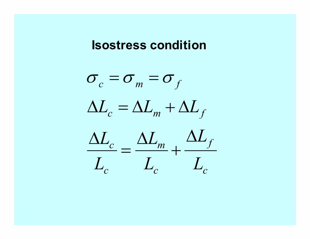
Isostress condition
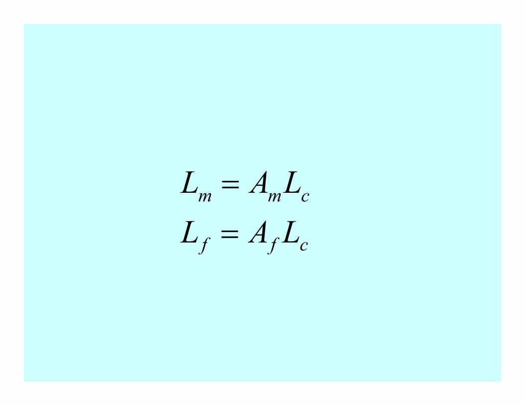
cff
cmm
LAL
LAL
=
=
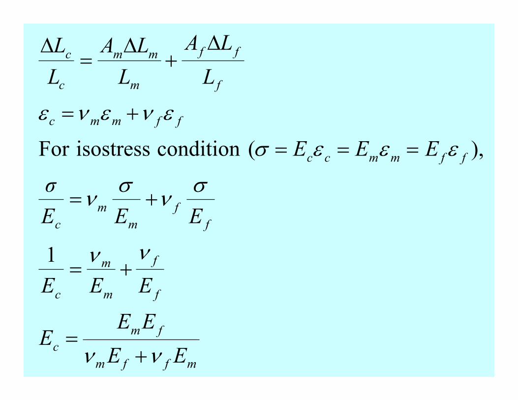
mffm
fm
c
f
f
m
m
c
f
f
m
m
c
ffmmcc
ffmmc
f
ff
m
mm
c
c
EE
EEE
EEE
EEE
σ
EEE
L
LA
L
LA
L
L
νν
νν
σν
σν
εεεσ
ενενε
+=
+=
+=
===
+=
∆+
∆=
∆
1
),(conditionisostressFor
mffm
fm
cXX
XXX
νν +=
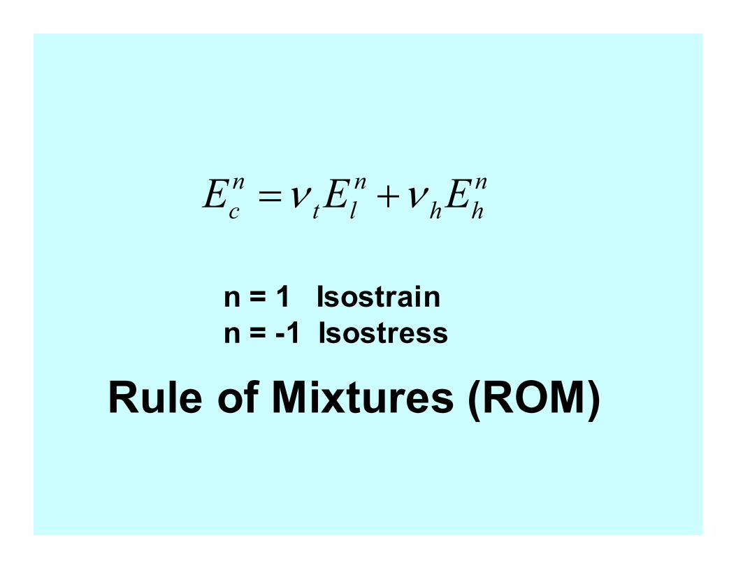
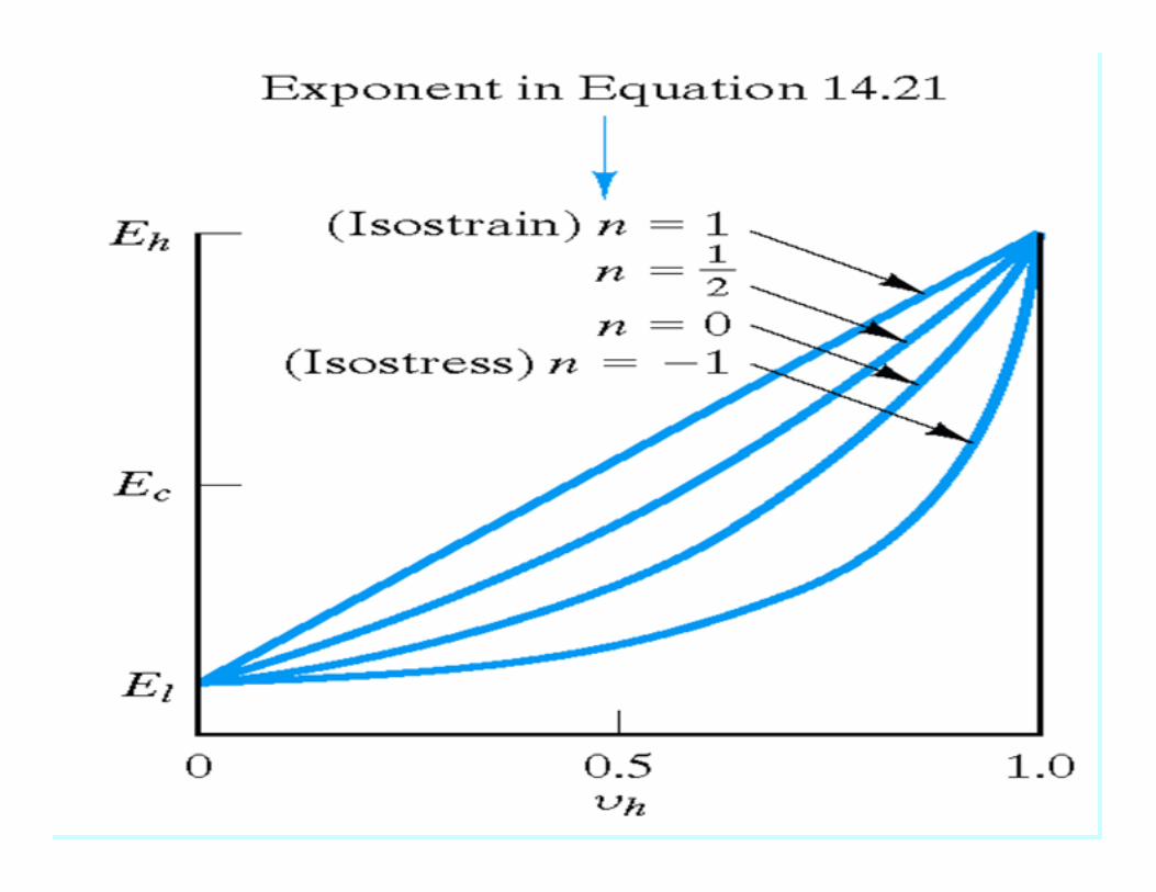
n
hh
n
lt
n
c EEE νν +=
n = 1 Isostrain
n = -1 Isostress
Rule of Mixtures (ROM)
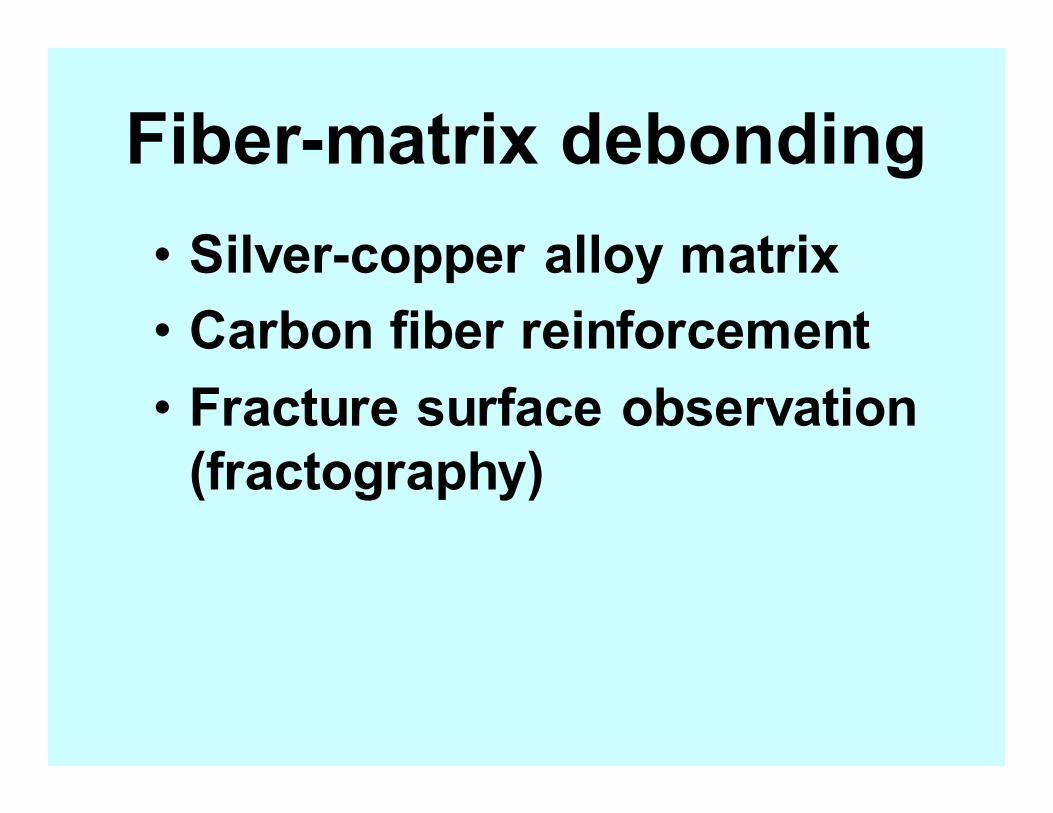
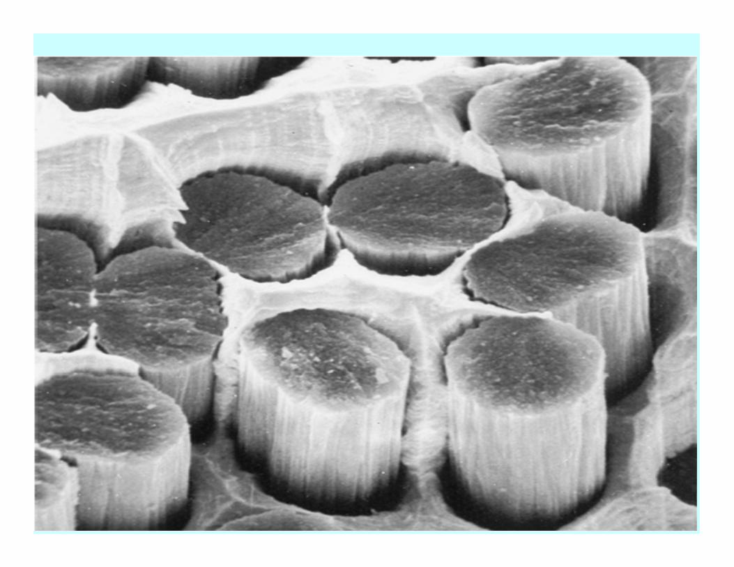
Fiber-matrix debonding
• Silver-copper alloy matrix
• Carbon fiber reinforcement
• Fracture surface observation
(fractography)
Fiber-matrix debonding
• Polymer matrix
• Glass fiber reinforcement
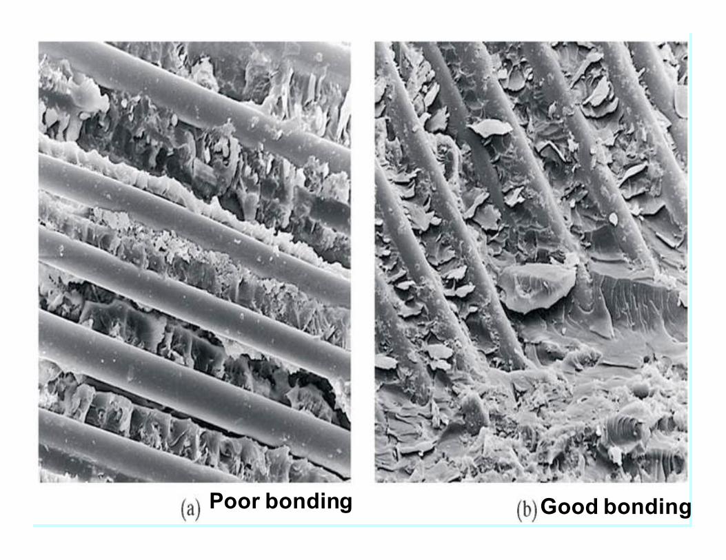
Poor bonding Good bonding
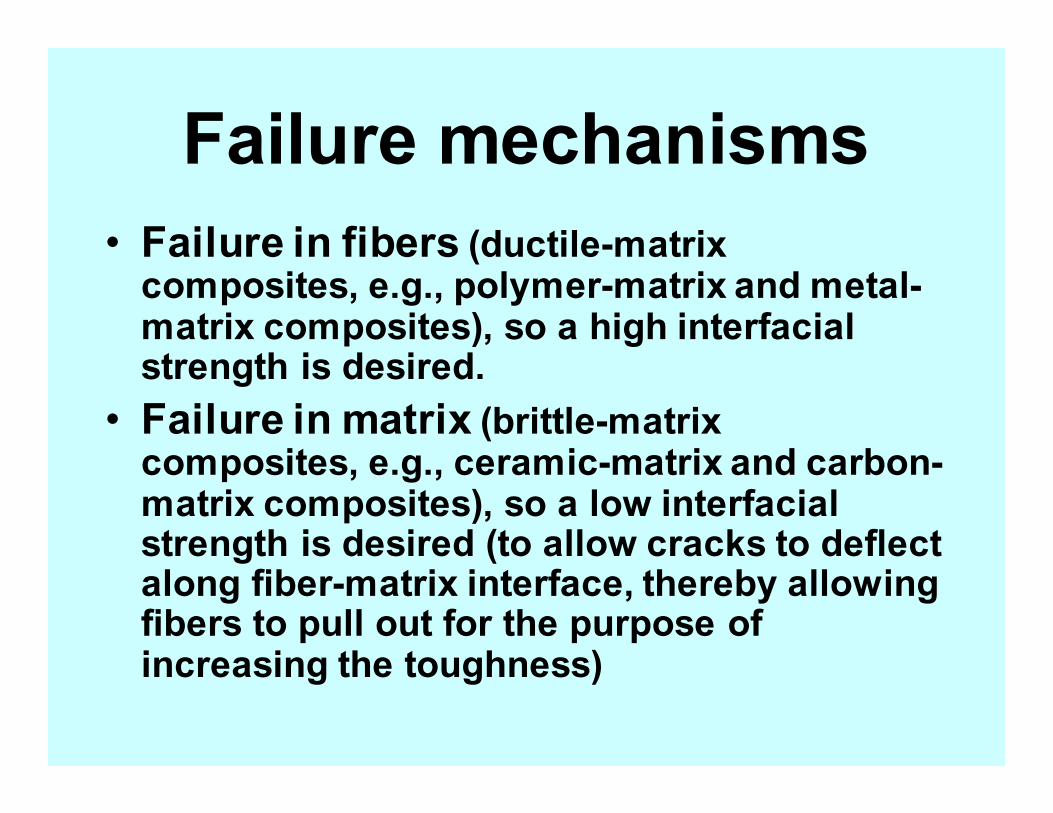
Failure mechanisms
• Failure in fibers (ductile-matrix composites, e.g., polymer-matrix and metal-matrix composites), so a high interfacial strength is desired.
• Failure in matrix (brittle-matrix composites, e.g., ceramic-matrix and carbon-matrix composites), so a low interfacial strength is desired (to allow cracks to deflect along fiber-matrix interface, thereby allowing fibers to pull out for the purpose of increasing the toughness)
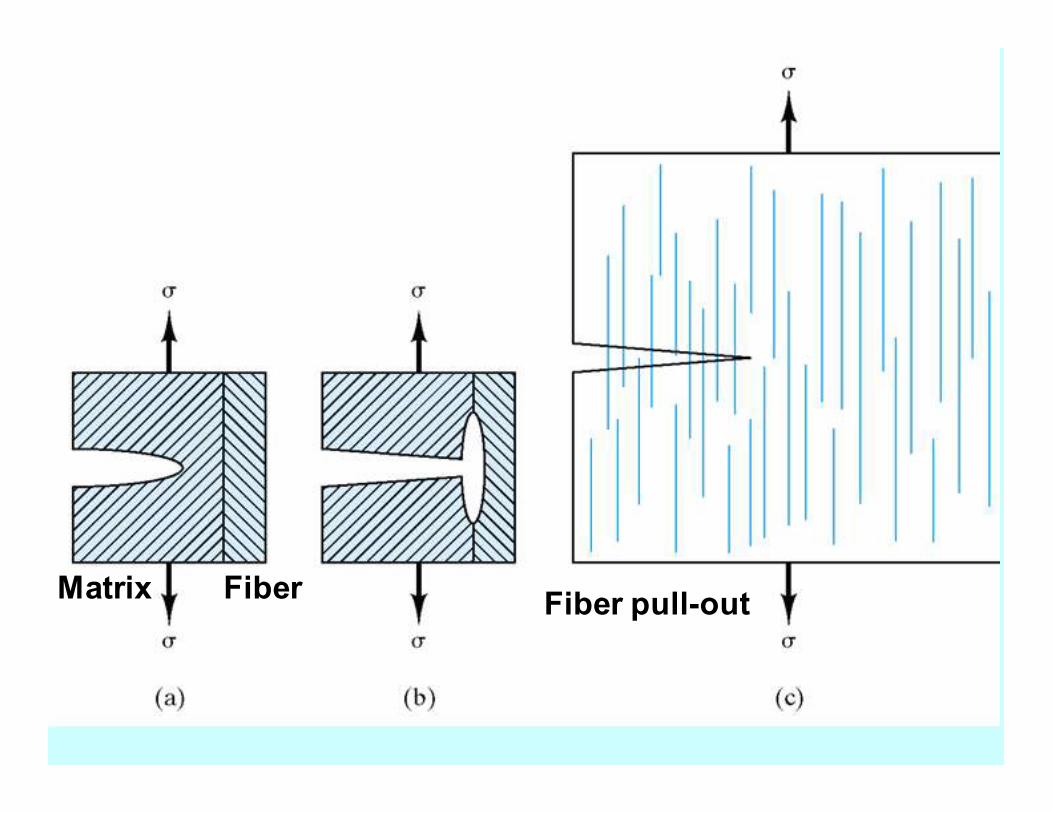
Fiber Matrix Fiber pull-out
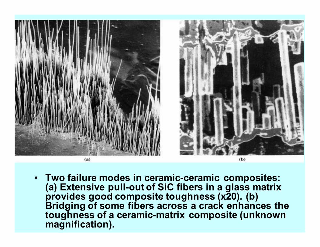
• Two failure modes in ceramic-ceramic composites: (a) Extensive pull-out of SiC fibers in a glass matrix provides good composite toughness (x20). (b) Bridging of some fibers across a crack enhances the toughness of a ceramic-matrix composite (unknown magnification).
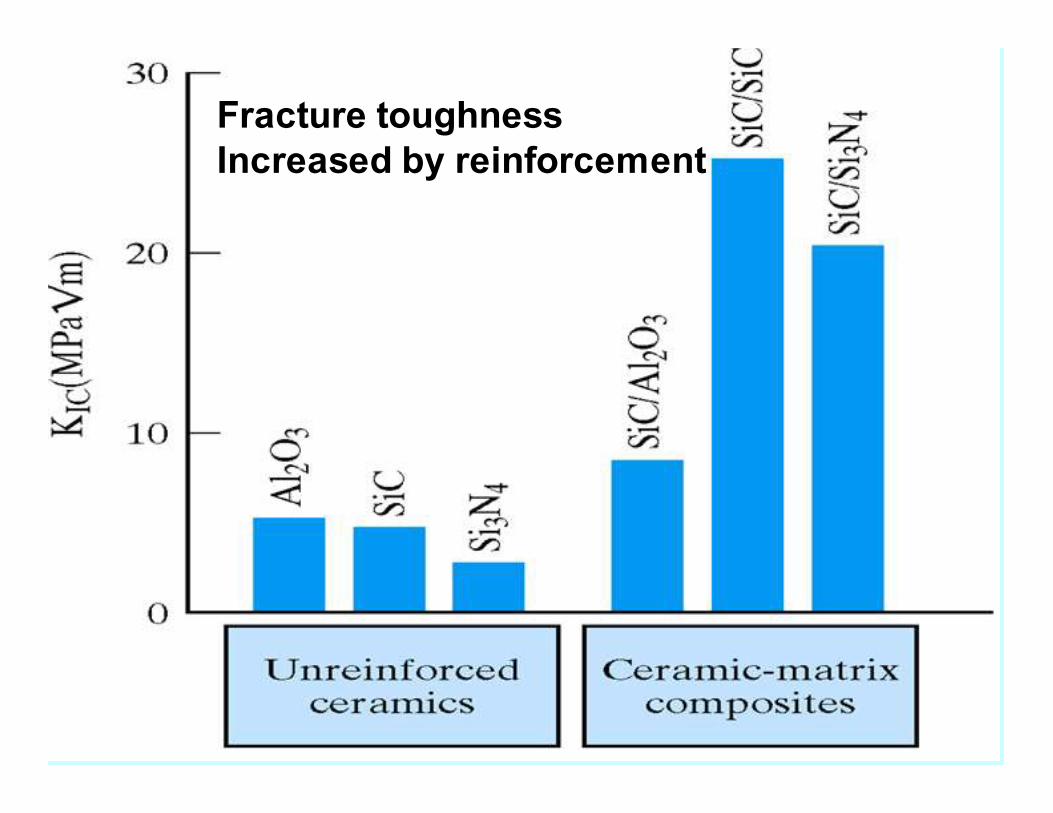
Fracture toughness
Increased by reinforcement
Specific strength = strength/density
Reasons for fiber-matrix
interface engineering
• To control fiber-matrix bond
strength (shear bond strength)
• To improve wetting of matrix
precursor on fiber
• To improve fiber dispersion
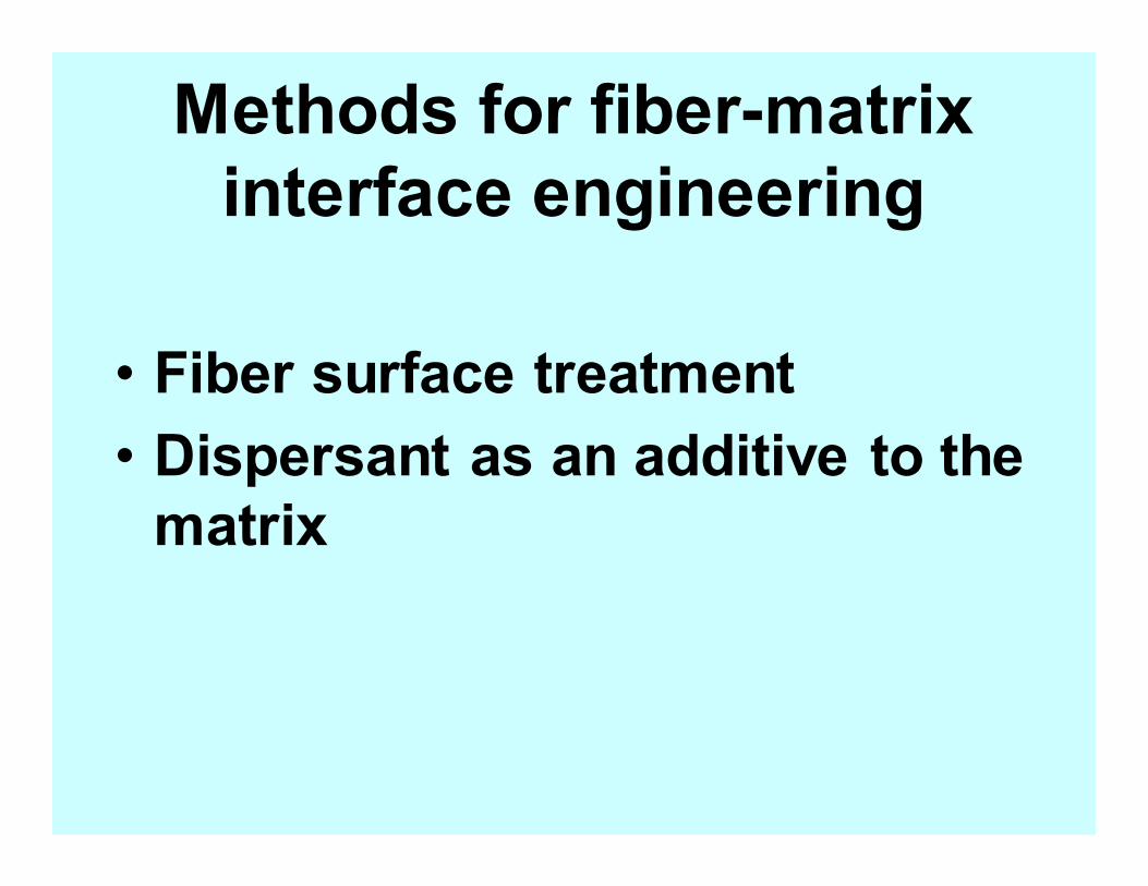
Methods for fiber-matrix
interface engineering
• Fiber surface treatment
• Dispersant as an additive to the
matrix
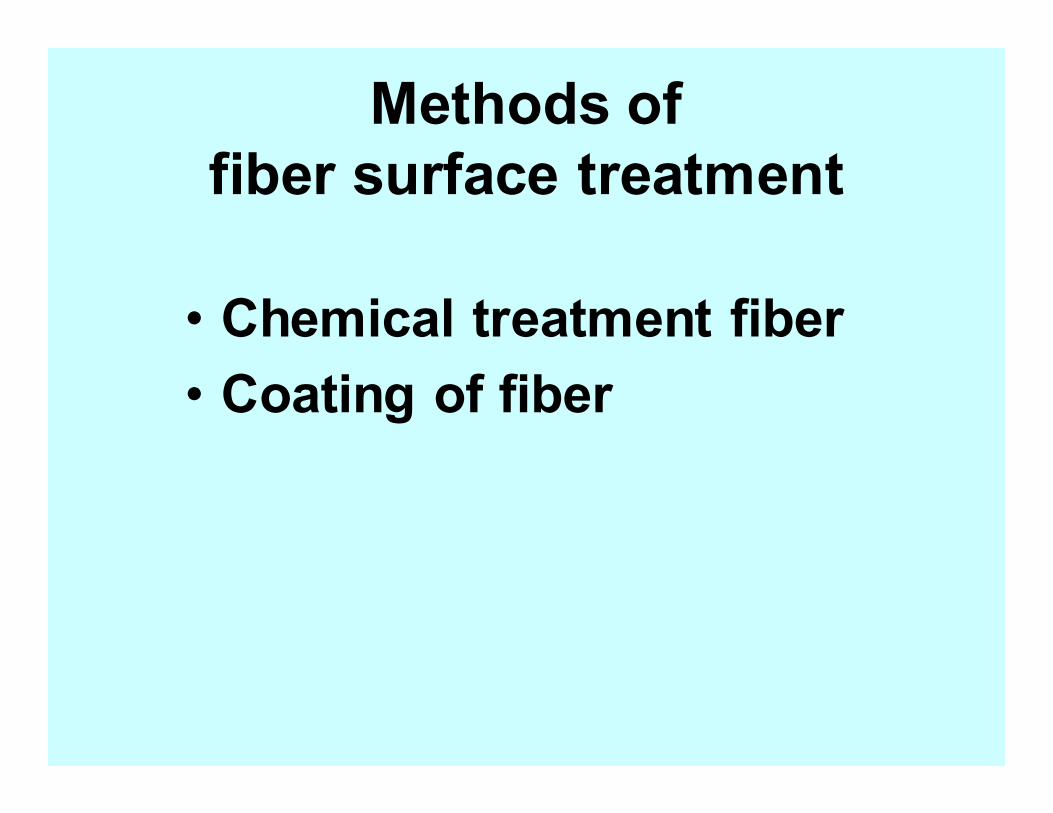
Methods of
fiber surface treatment
• Chemical treatment fiber
• Coating of fiber
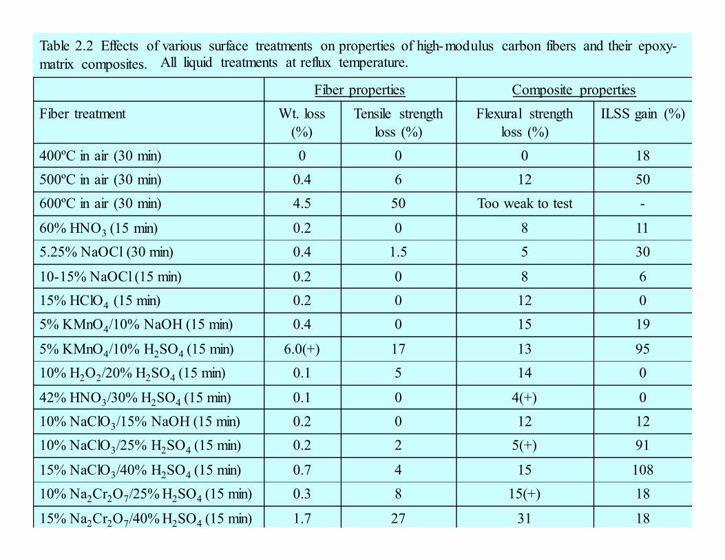
Table 2.2 Effects of various surface treatments on properties of high-modulus carbon fibers and their epoxy-
matrix composites.
Fiber properties Composite properties
Fiber treatment Wt. loss
(%)
Tensile strength
loss (%)
Flexural strength
loss (%)
ILSS gain (%)
400ºC in air (30 min) 0 0 0 18
500ºC in air (30 min) 0.4 6 12 50
600ºC in air (30 min) 4.5 50 Too weak to test -
60% HNO3 (15 min) 0.2 0 8 11
5.25% NaOCl (30 min) 0.4 1.5 5 30
10-15% NaOCl (15 min) 0.2 0 8 6
15% HClO4 (15 min) 0.2 0 12 0
5% KMnO4/10% NaOH (15 min) 0.4 0 15 19
5% KMnO4/10% H2SO4 (15 min) 6.0(+) 17 13 95
10% H2O2/20% H2SO4 (15 min) 0.1 5 14 0
42% HNO3/30% H2SO4 (15 min) 0.1 0 4(+) 0
10% NaClO3/15% NaOH (15 min) 0.2 0 12 12
10% NaClO3/25% H2SO4 (15 min) 0.2 2 5(+) 91
15% NaClO3/40% H2SO4 (15 min) 0.7 4 15 108
10% Na2Cr2O7/25% H2SO4 (15 min) 0.3 8 15(+) 18
15% Na2Cr2O7/40% H2SO4 (15 min) 1.7 27 31 18
All liquid treatments at reflux temperature.
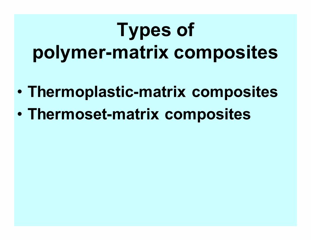
Types of
polymer-matrix composites
• Thermoplastic-matrix composites
• Thermoset-matrix composites
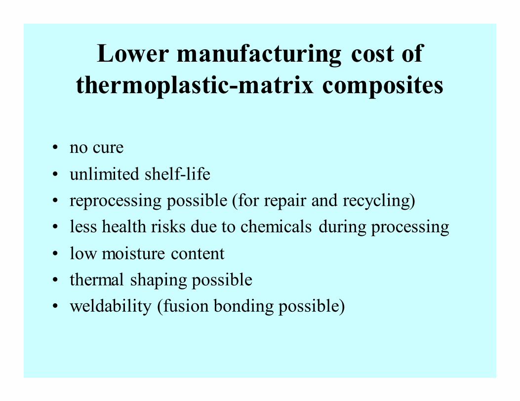
Lower manufacturing cost of
thermoplastic-matrix composites
• no cure
• unlimited shelf-life
• reprocessing possible (for repair and recycling)
• less health risks due to chemicals during processing
• low moisture content
• thermal shaping possible
• weldability (fusion bonding possible)
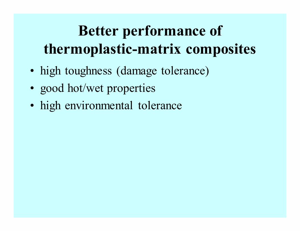
Better performance of
thermoplastic-matrix composites
• high toughness (damage tolerance)
• good hot/wet properties
• high environmental tolerance
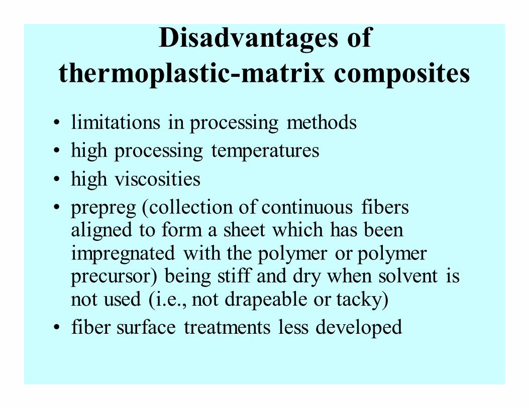
Disadvantages of
thermoplastic-matrix composites
• limitations in processing methods
• high processing temperatures
• high viscosities
• prepreg (collection of continuous fibers aligned to form a sheet which has been impregnated with the polymer or polymer precursor) being stiff and dry when solvent is not used (i.e., not drapeable or tacky)
• fiber surface treatments less developed
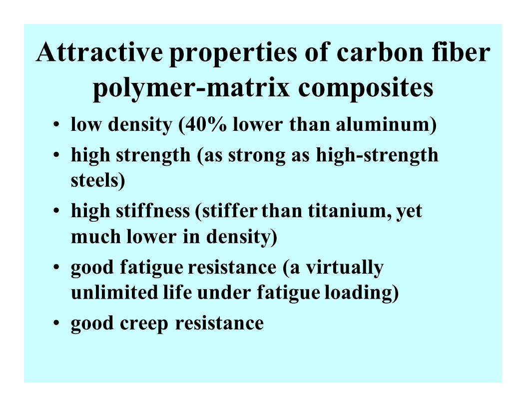
Attractive properties of carbon fiber
polymer-matrix composites
• low density (40% lower than aluminum)
• high strength (as strong as high-strength
steels)
• high stiffness (stiffer than titanium, yet
much lower in density)
• good fatigue resistance (a virtually
unlimited life under fatigue loading)
• good creep resistance
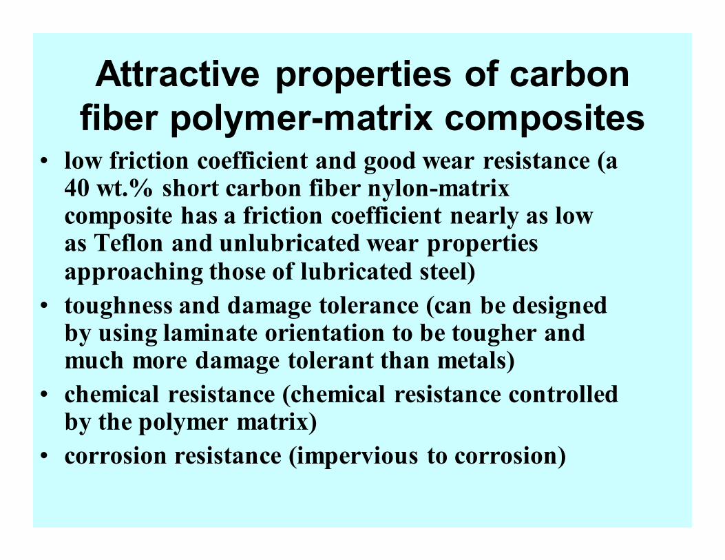
Attractive properties of carbon
fiber polymer-matrix composites • low friction coefficient and good wear resistance (a 40 wt.% short carbon fiber nylon-matrix composite has a friction coefficient nearly as low as Teflon and unlubricated wear properties approaching those of lubricated steel)
• toughness and damage tolerance (can be designed by using laminate orientation to be tougher and much more damage tolerant than metals)
• chemical resistance (chemical resistance controlled by the polymer matrix)
• corrosion resistance (impervious to corrosion)
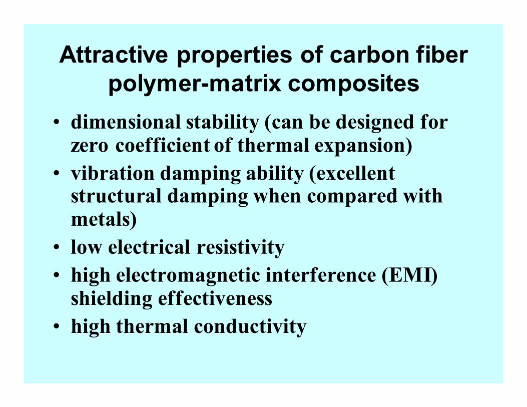
Attractive properties of carbon fiber
polymer-matrix composites
• dimensional stability (can be designed for zero coefficient of thermal expansion)
• vibration damping ability (excellent structural damping when compared with metals)
• low electrical resistivity
• high electromagnetic interference (EMI) shielding effectiveness
• high thermal conductivity
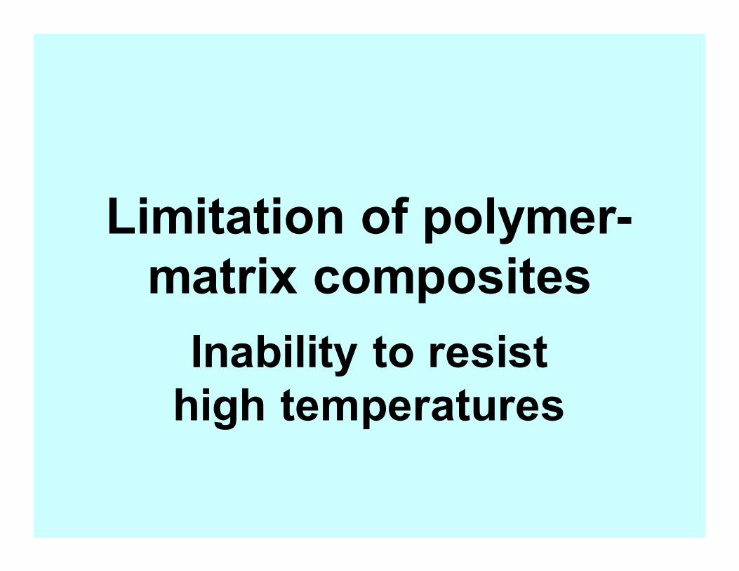
Limitation of polymer-
matrix composites
Inability to resist
high temperatures
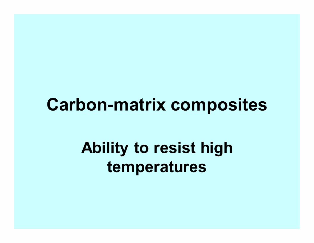
Carbon-matrix composites
Ability to resist high
temperatures
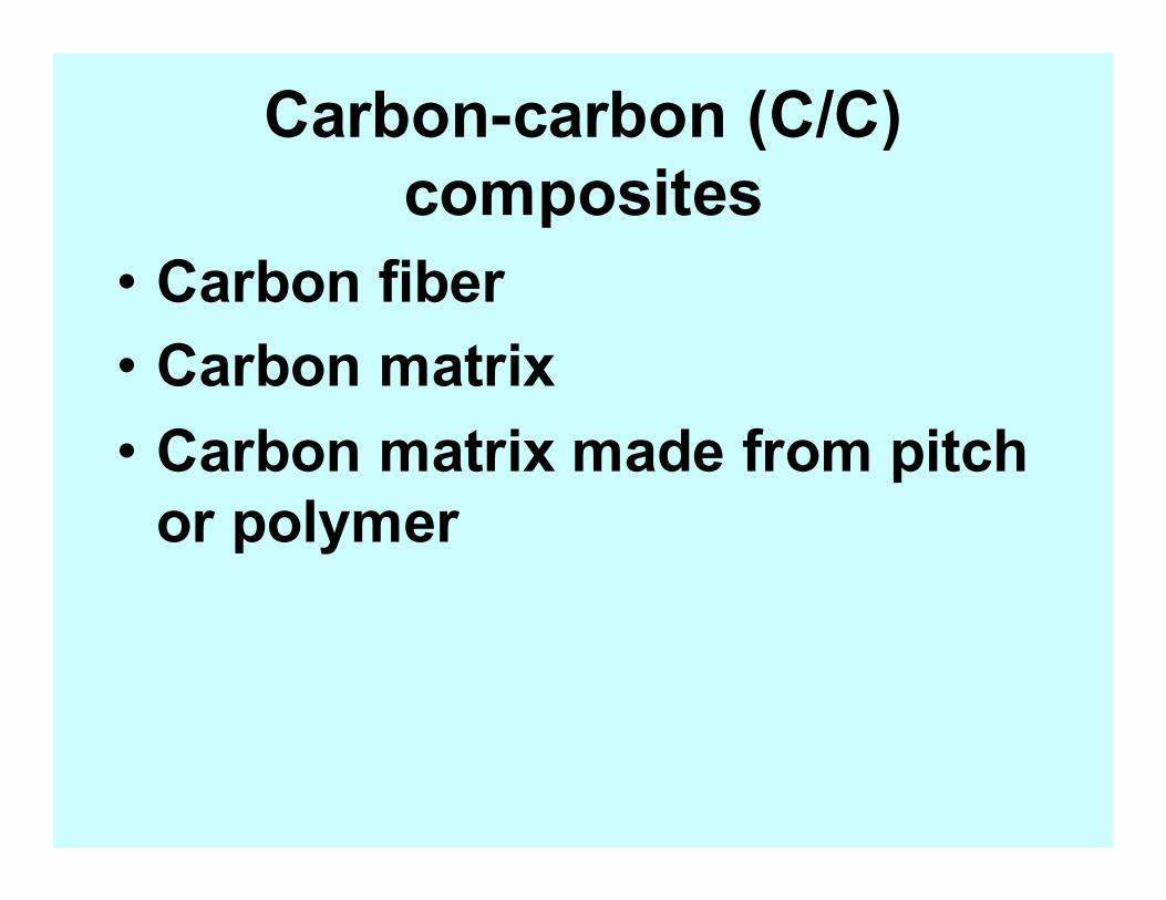
Carbon-carbon (C/C)
composites
• Carbon fiber
• Carbon matrix
• Carbon matrix made from pitch
or polymer
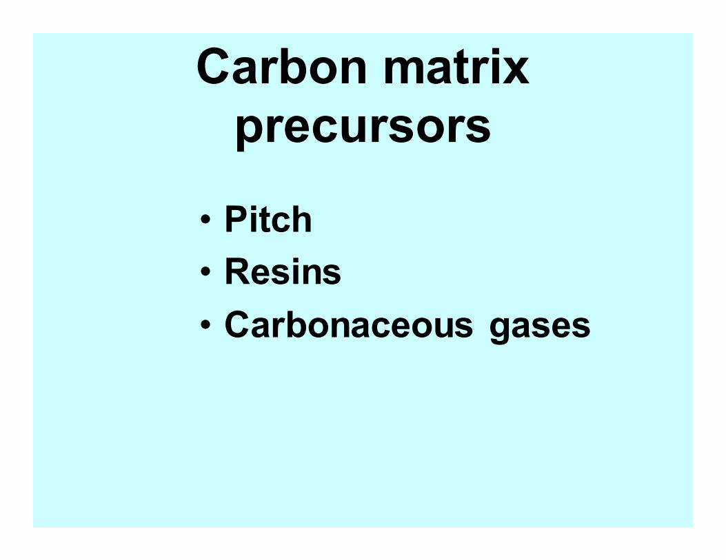
Carbon matrix
precursors
• Pitch
• Resins
• Carbonaceous gases
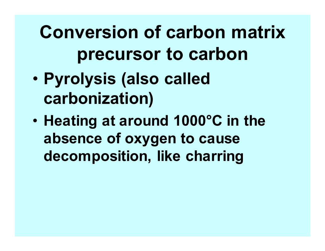
Conversion of carbon matrix
precursor to carbon
• Pyrolysis (also called
carbonization)
• Heating at around 1000°C in the
absence of oxygen to cause
decomposition, like charring
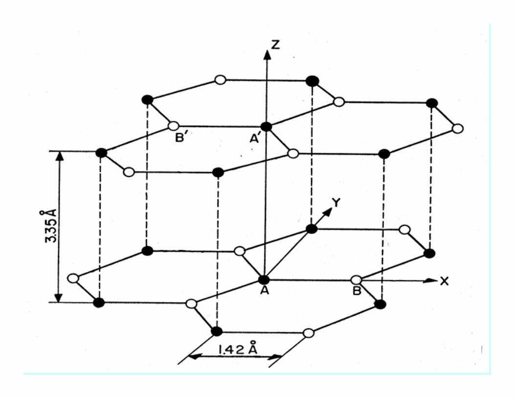
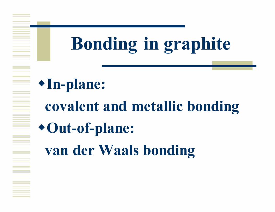
Bonding in graphite
�In-plane:
covalent and metallic bonding
�Out-of-plane:
van der Waals bonding
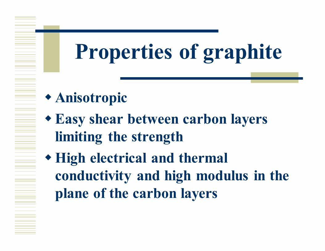
Properties of graphite
�Anisotropic
�Easy shear between carbon layers
limiting the strength
�High electrical and thermal
conductivity and high modulus in the
plane of the carbon layers
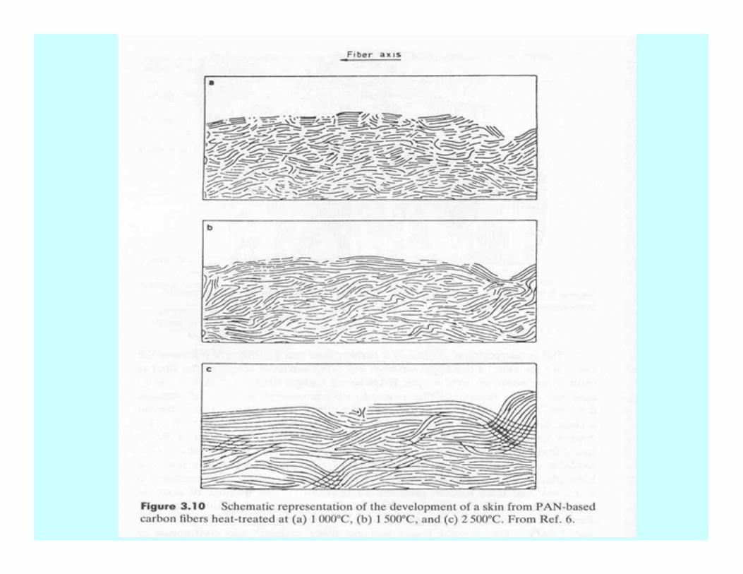
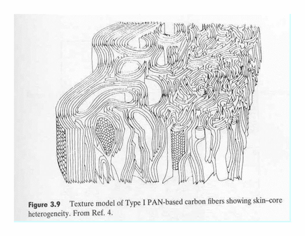
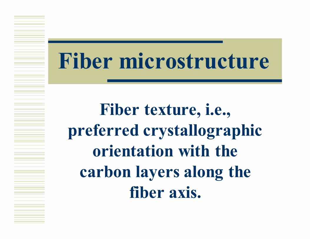
Fiber microstructure
Fiber texture, i.e.,
preferred crystallographic
orientation with the
carbon layers along the
fiber axis.
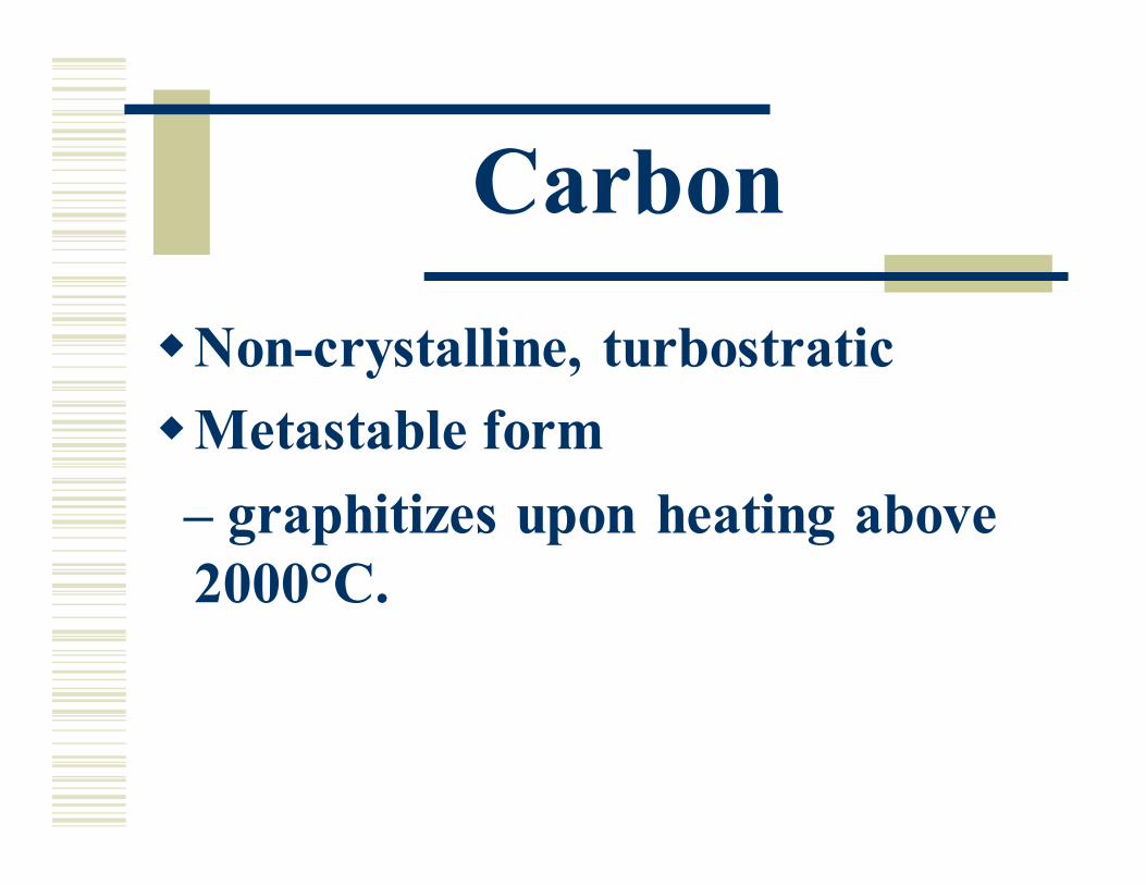
Carbon
�Non-crystalline, turbostratic
�Metastable form
– graphitizes upon heating above
2000°C.
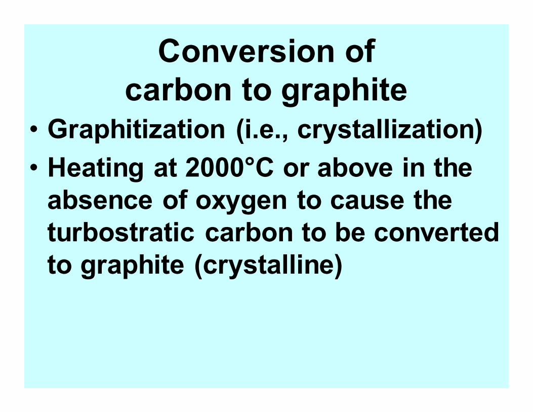
Conversion of
carbon to graphite • Graphitization (i.e., crystallization)
• Heating at 2000°C or above in the
absence of oxygen to cause the
turbostratic carbon to be converted
to graphite (crystalline)
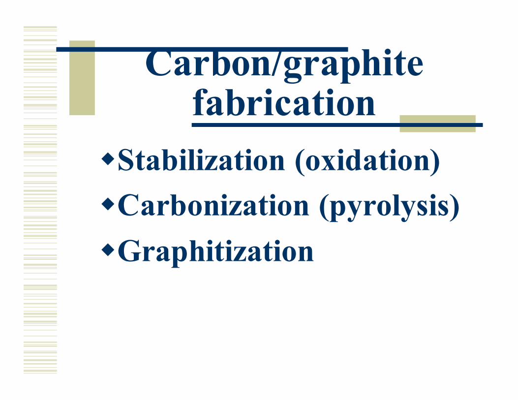
Carbon/graphite fabrication
�Stabilization (oxidation)
�Carbonization (pyrolysis)
�Graphitization
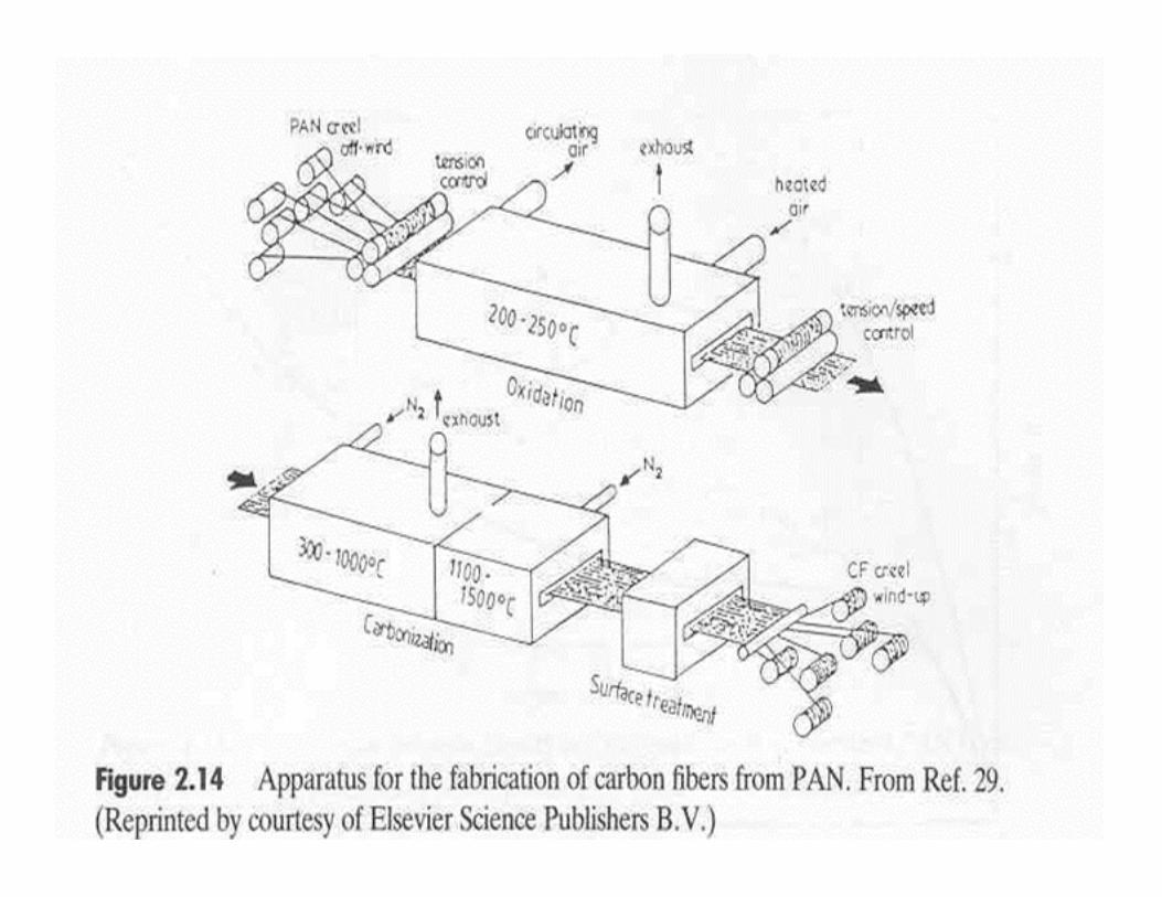
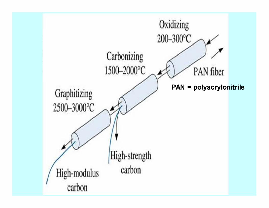
PAN = polyacrylonitrile
Grades of carbon fiber
• High-strength carbon fiber
(without graphization)
• High-modulus carbon fiber
(with graphitization)

©2003 B
rooks/Cole, a division of Thomson Learning, Inc. Thomson Learning™ is a trademark used herein under license.
Properties of carbon compared to graphite
�Less conductive
�Lower in modulus
�Higher in strength
�Lower in oxidation resistance
�Cannot be intercalated
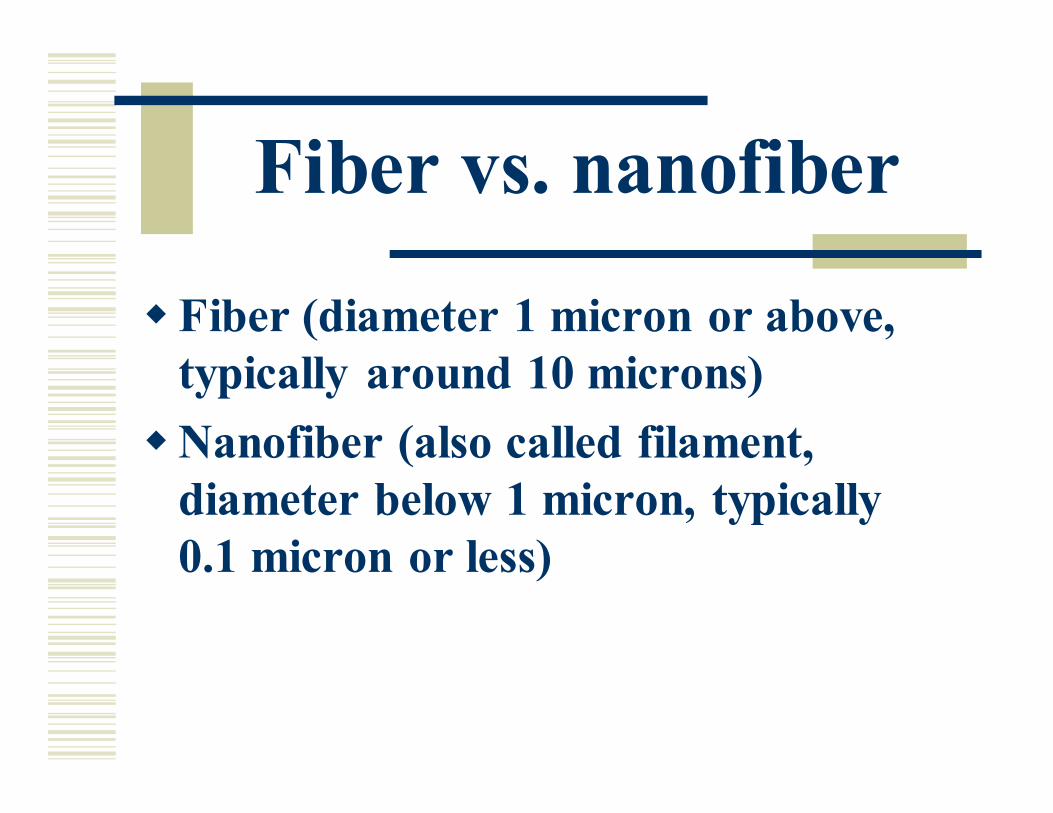
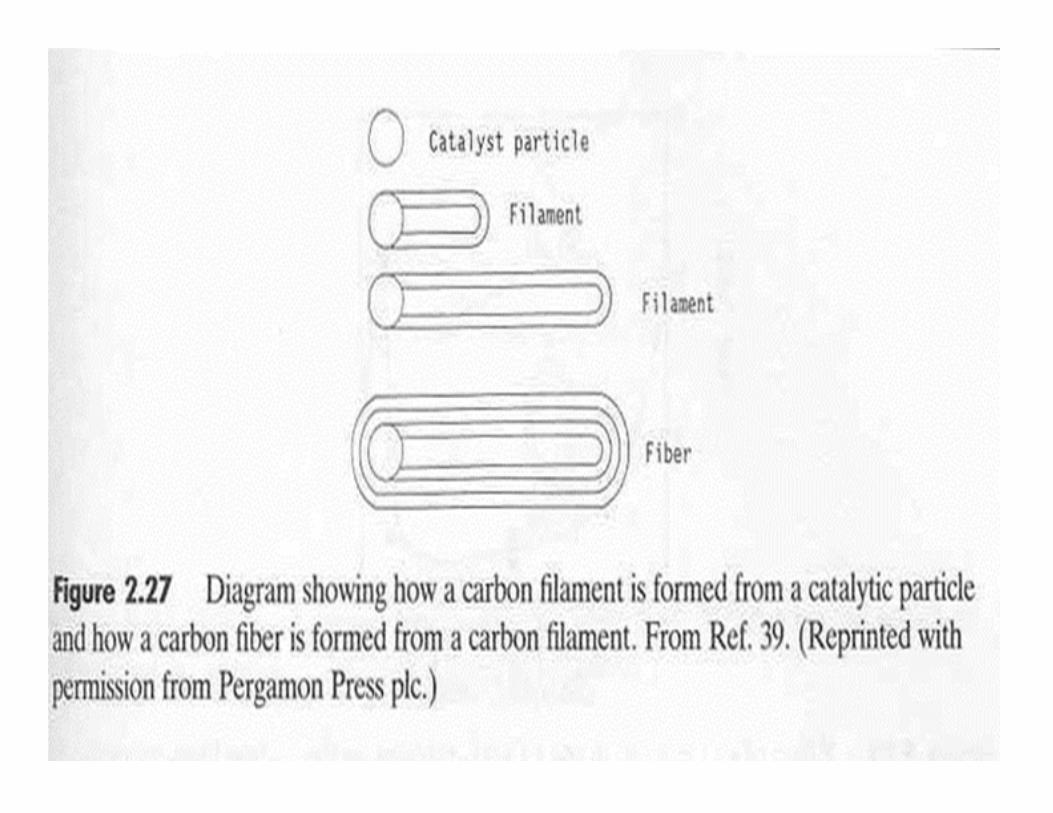
Fiber vs. nanofiber
�Fiber (diameter 1 micron or above,
typically around 10 microns)
�Nanofiber (also called filament,
diameter below 1 micron, typically
0.1 micron or less)
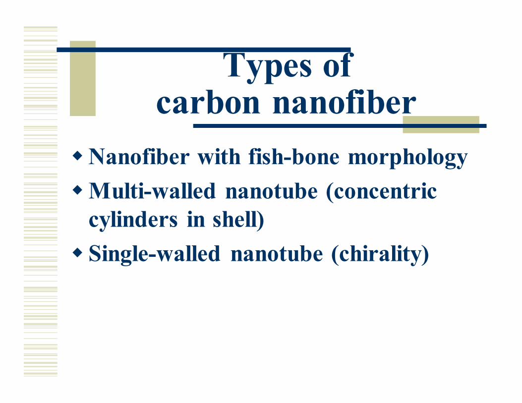
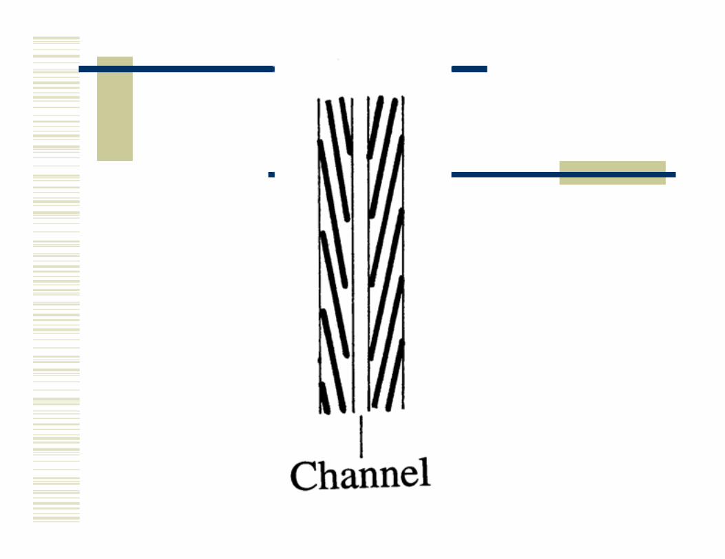
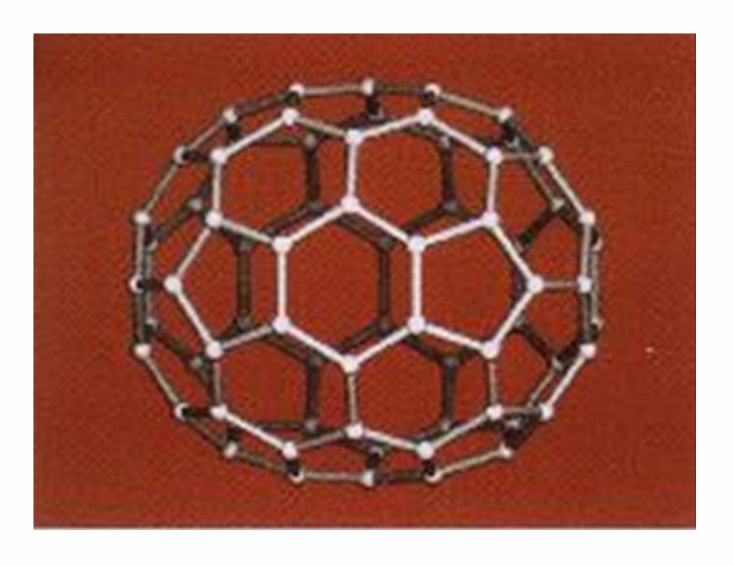
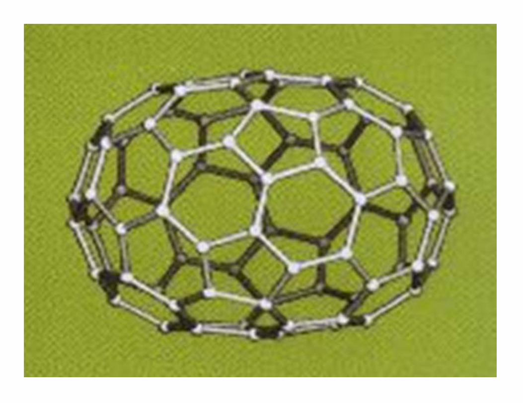
Types of carbon nanofiber
�Nanofiber with fish-bone morphology
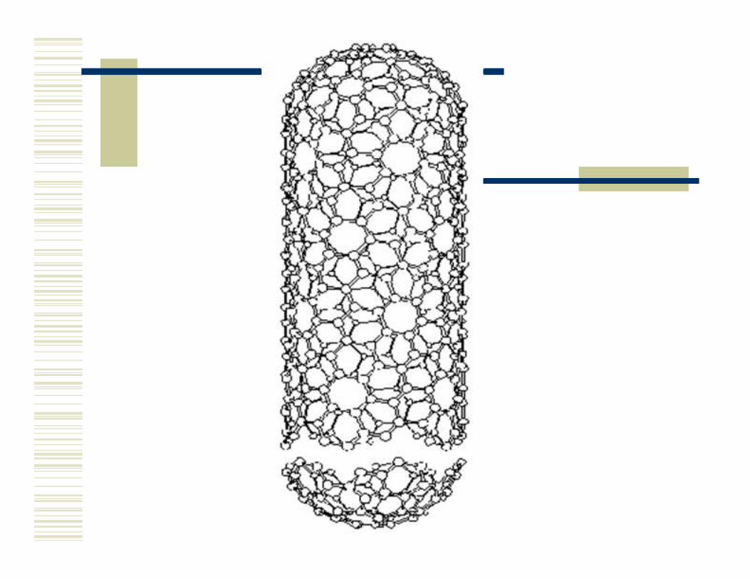
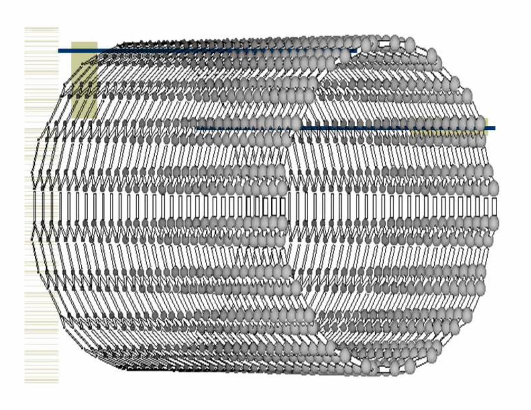
�Multi-walled nanotube (concentric
cylinders in shell)
� Single-walled nanotube (chirality)
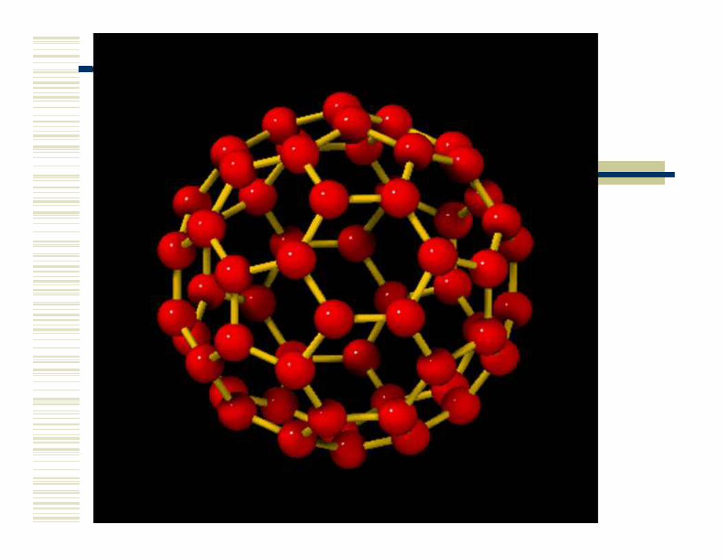
Carbon nanotube
Hybrid of graphite and
fullerene
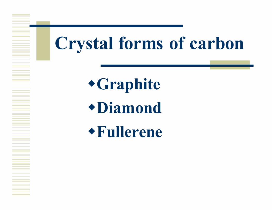
Crystal forms of carbon
�Graphite
�Diamond
�Fullerene
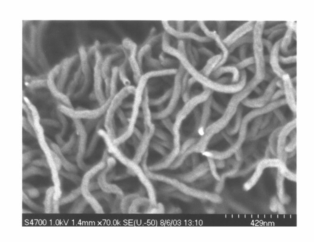
Nanofiber group morphology
�Intertwined
�Parallel
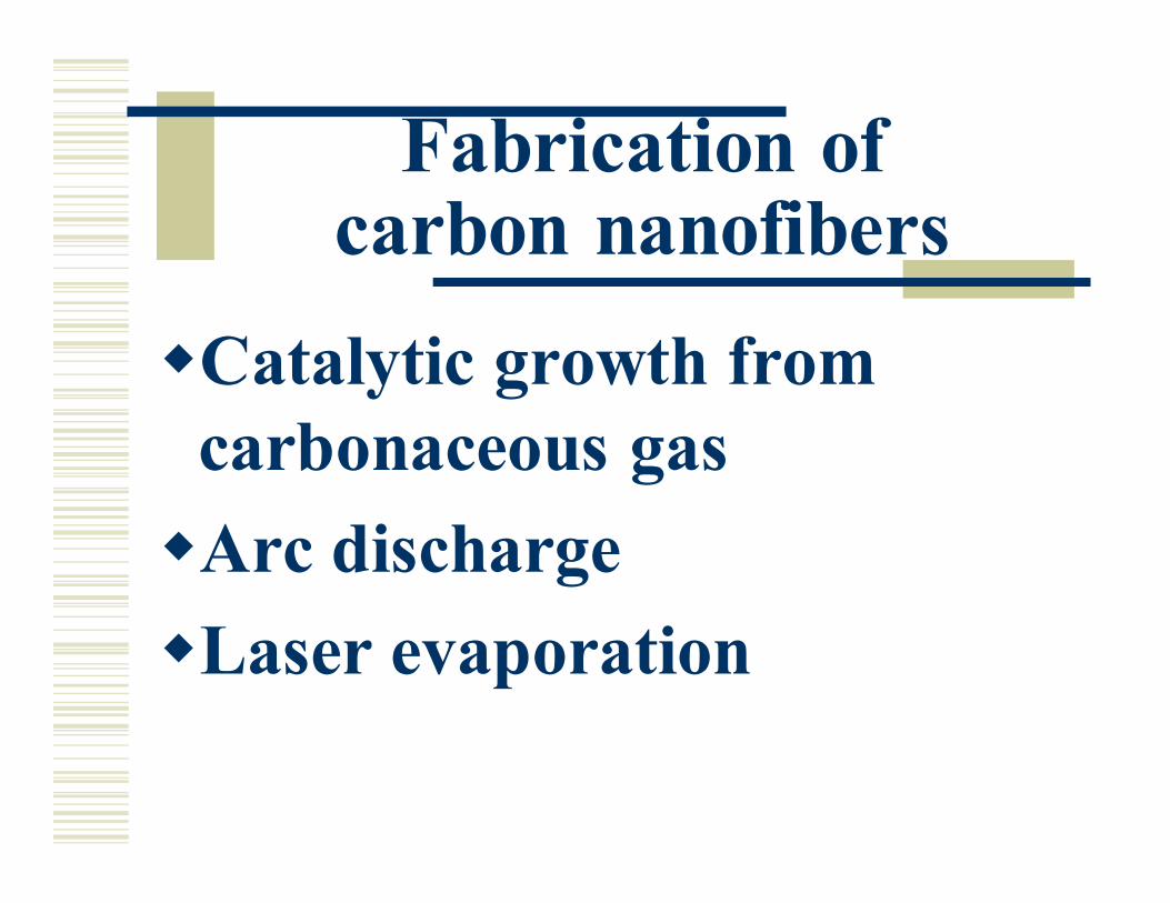
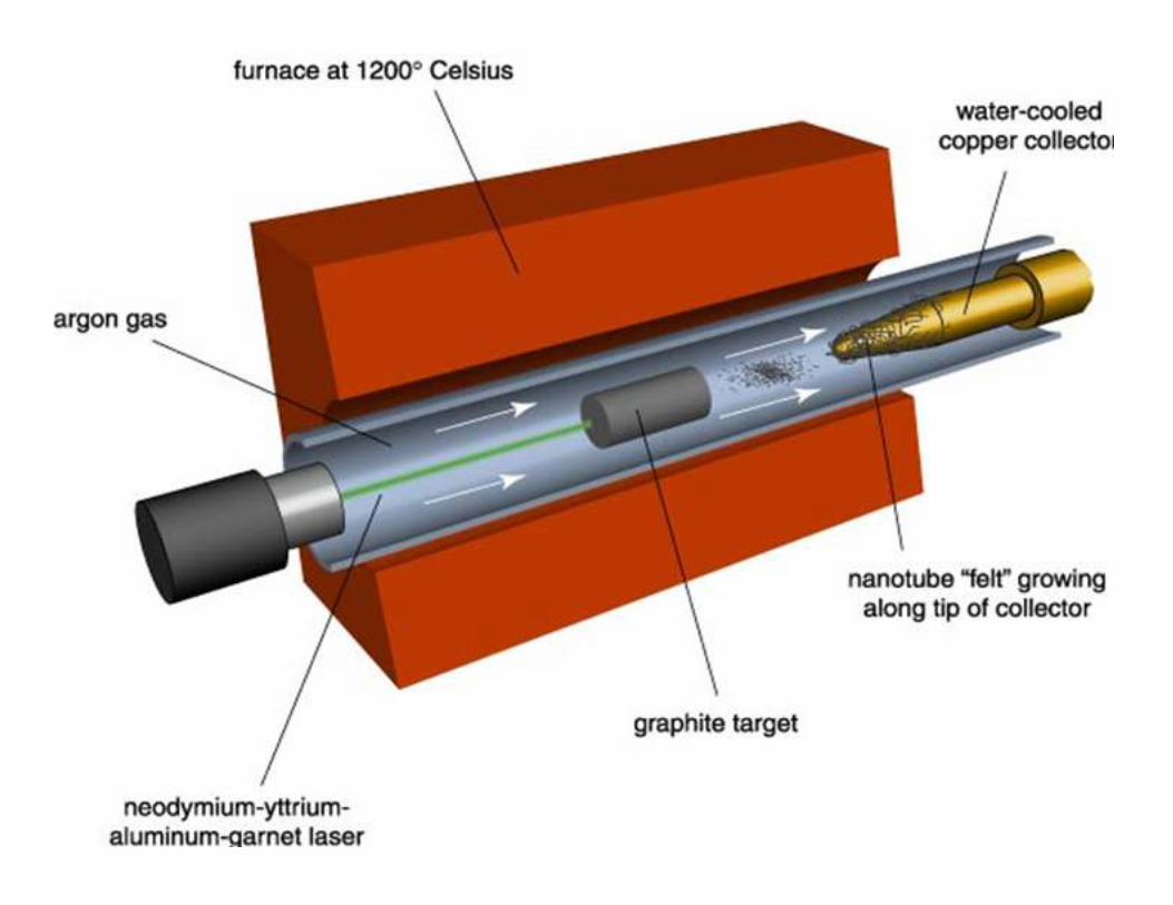
Fabrication of carbon nanofibers
�Catalytic growth from
carbonaceous gas
�Arc discharge
�Laser evaporation
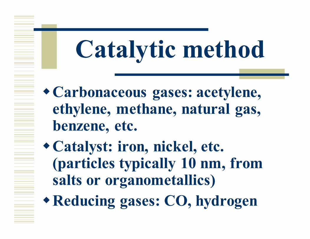
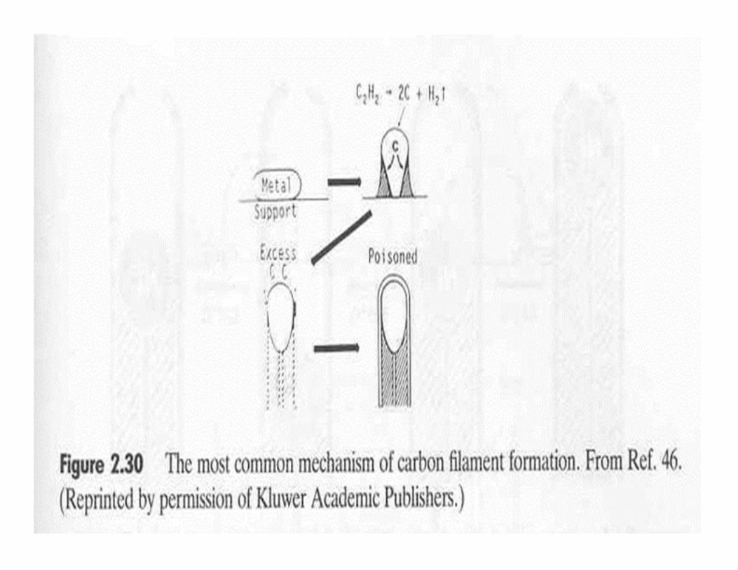
Catalytic method
�Carbonaceous gases: acetylene, ethylene, methane, natural gas, benzene, etc.
�Catalyst: iron, nickel, etc. (particles typically 10 nm, from salts or organometallics)
�Reducing gases: CO, hydrogen
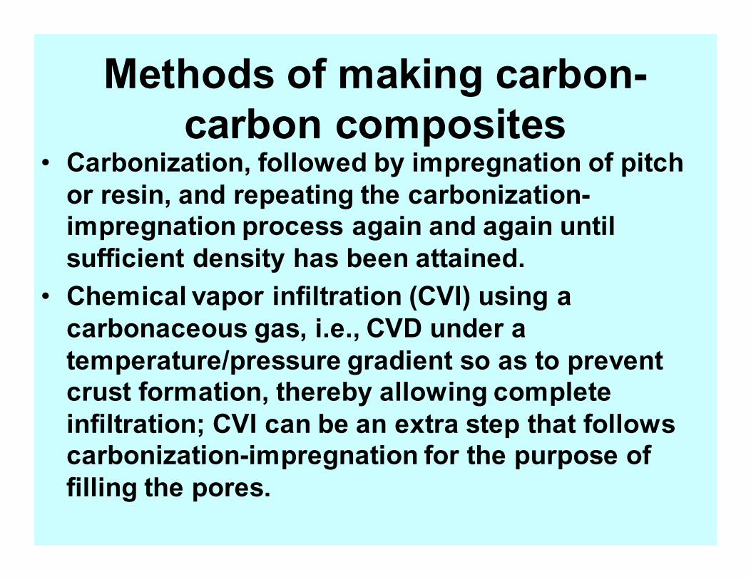
Methods of making carbon-
carbon composites • Carbonization, followed by impregnation of pitch
or resin, and repeating the carbonization-
impregnation process again and again until
sufficient density has been attained.
• Chemical vapor infiltration (CVI) using a
carbonaceous gas, i.e., CVD under a
temperature/pressure gradient so as to prevent
crust formation, thereby allowing complete
infiltration; CVI can be an extra step that follows
carbonization-impregnation for the purpose of
filling the pores.
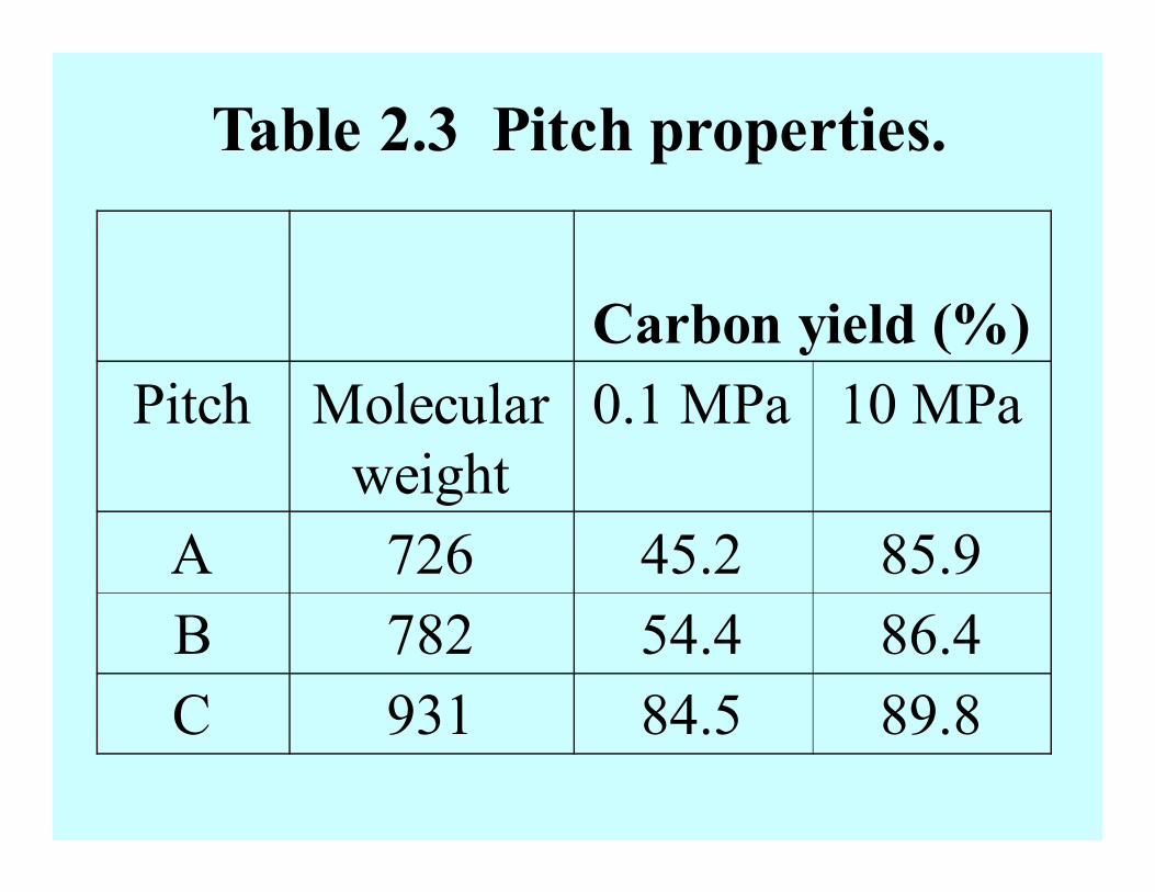
Table 2.3 Pitch properties.
Carbon yield (%)
Pitch Molecular
weight
0.1 MPa 10 MPa
A 726 45.2 85.9
B 782 54.4 86.4
C 931 84.5 89.8
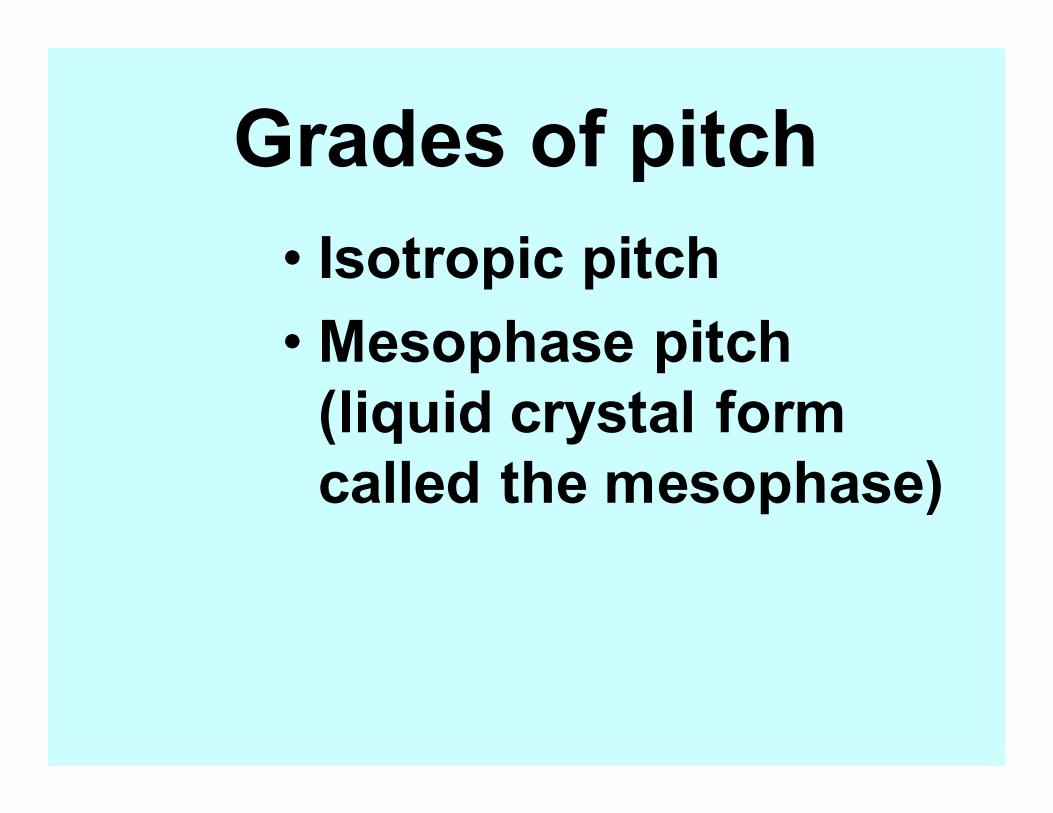
Grades of pitch
• Isotropic pitch
• Mesophase pitch
(liquid crystal form
called the mesophase)
Main problem with
carbon-carbon composites
Oxidation at high temperatures
in the presence of oxygen
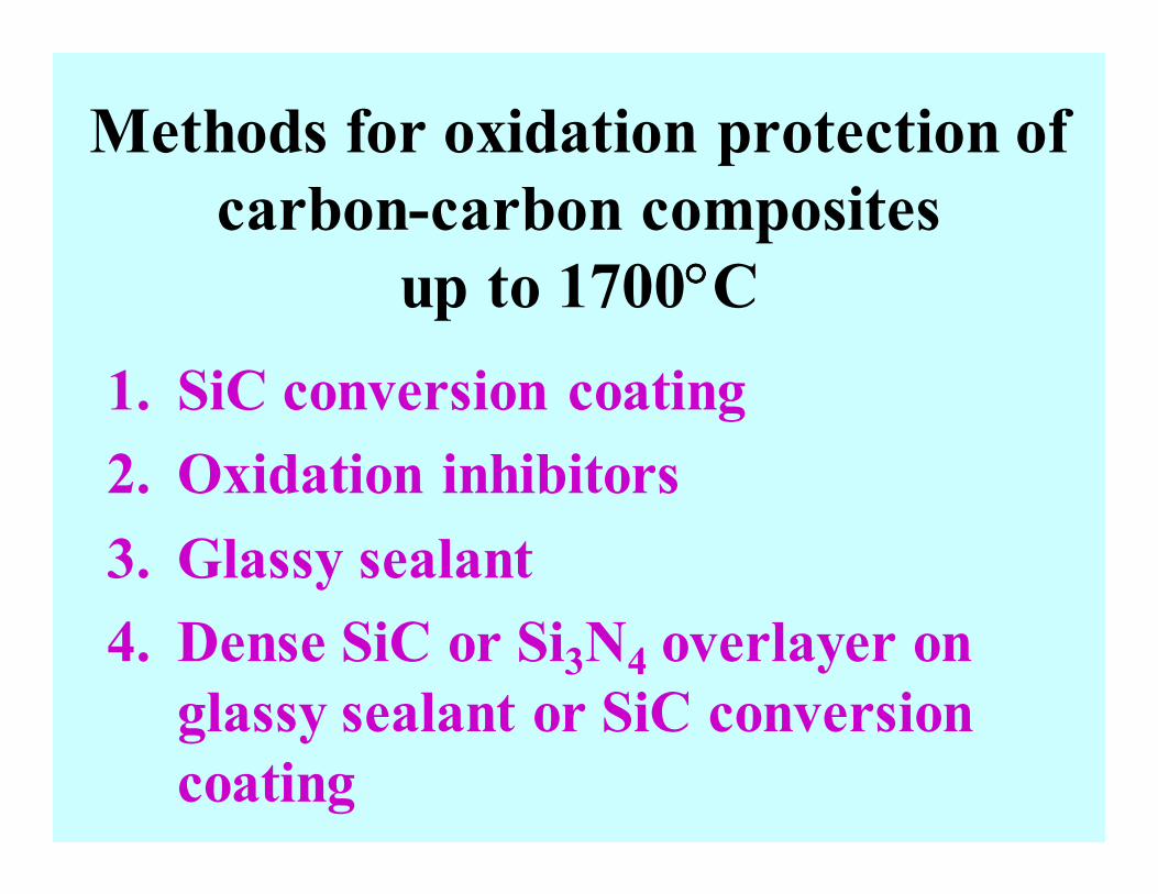
Methods for oxidation protection of
carbon-carbon composites
up to 1700°°°°C
1. SiC conversion coating
2. Oxidation inhibitors
3. Glassy sealant
4. Dense SiC or Si3N4 overlayer on
glassy sealant or SiC conversion
coating
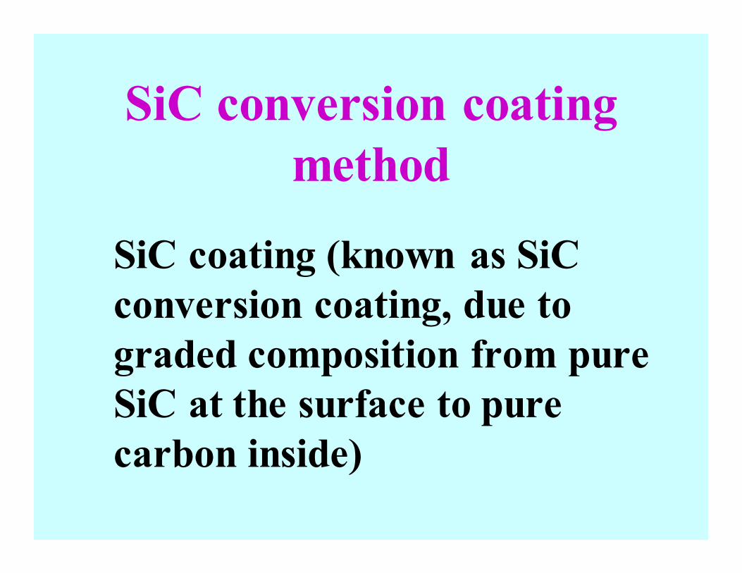
SiC conversion coating
method
SiC coating (known as SiC
conversion coating, due to
graded composition from pure
SiC at the surface to pure
carbon inside)
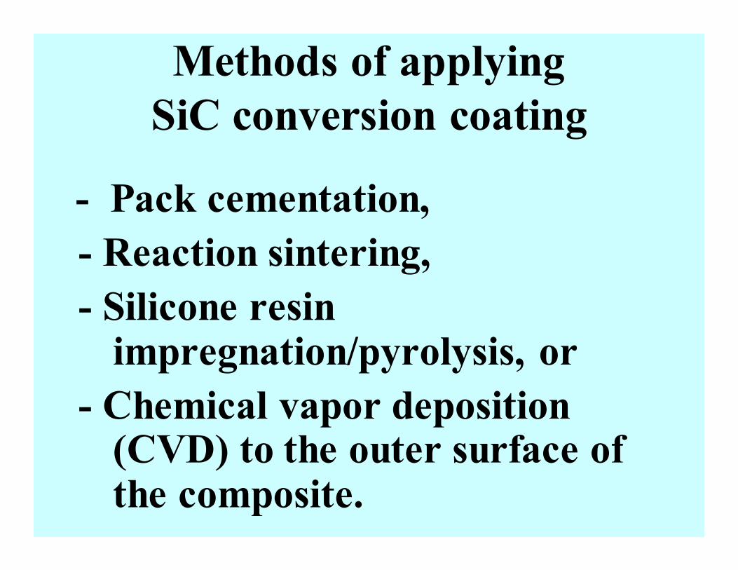
Methods of applying
SiC conversion coating
- Pack cementation,
- Reaction sintering,
- Silicone resin impregnation/pyrolysis, or
- Chemical vapor deposition (CVD) to the outer surface of the composite.
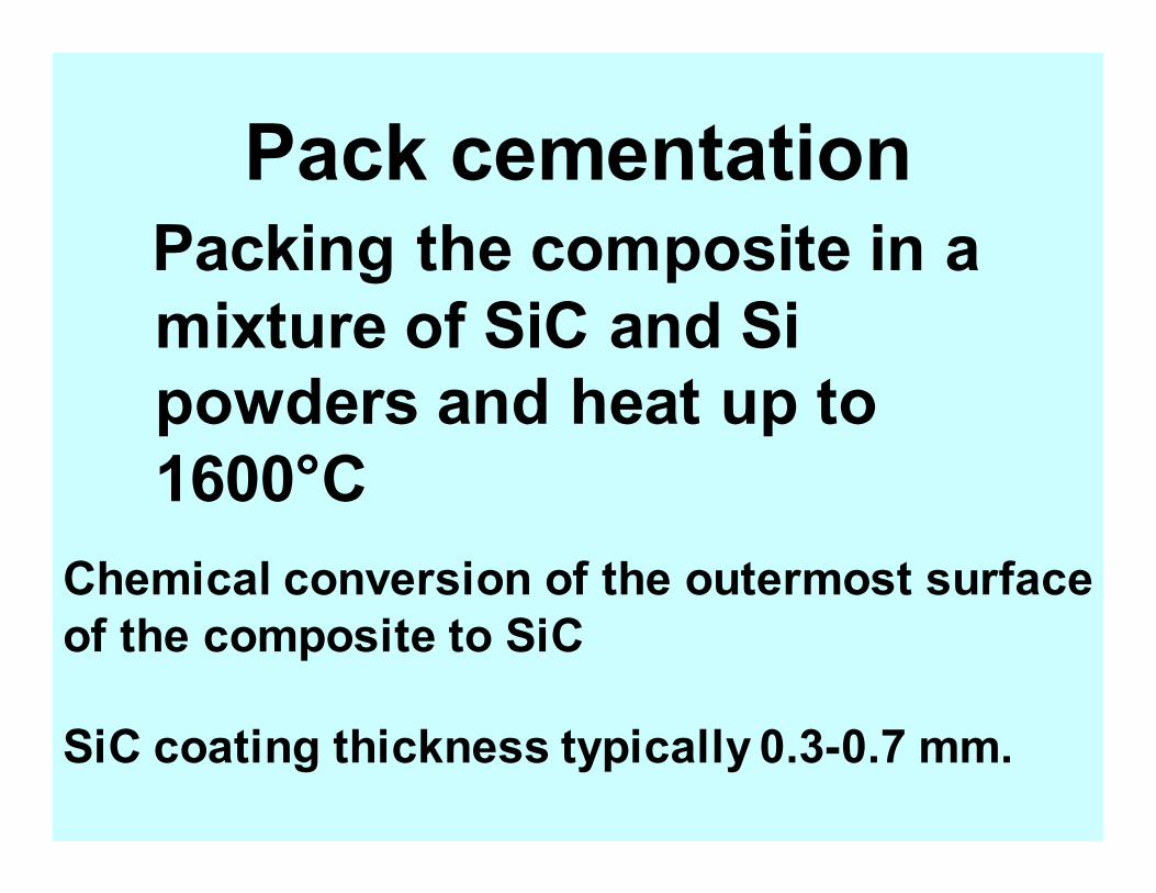
Pack cementation Packing the composite in a
mixture of SiC and Si
powders and heat up to
1600°C
Chemical conversion of the outermost surface
of the composite to SiC
SiC coating thickness typically 0.3-0.7 mm.
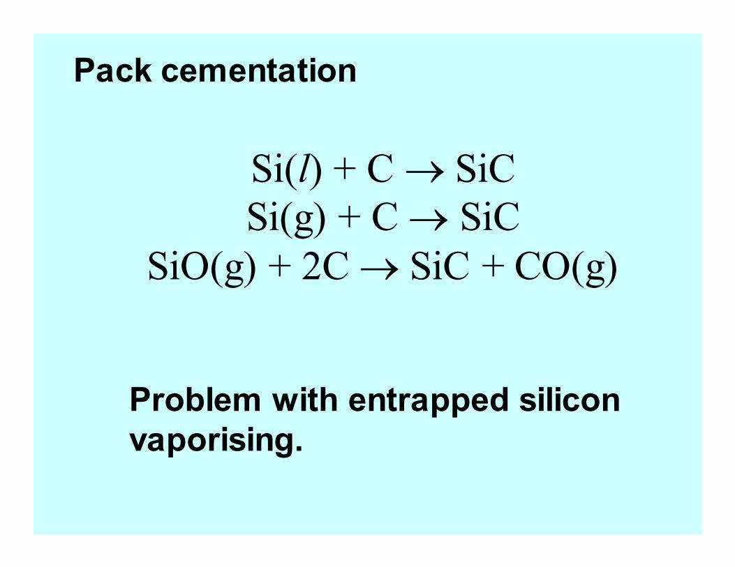
Si(l) + C → SiC
Si(g) + C → SiC
SiO(g) + 2C → SiC + CO(g)
Pack cementation
Problem with entrapped silicon
vaporising.
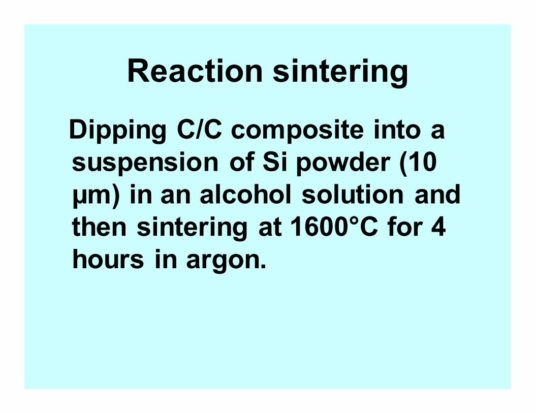
Reaction sintering
Dipping C/C composite into a
suspension of Si powder (10
µm) in an alcohol solution and
then sintering at 1600°C for 4
hours in argon.
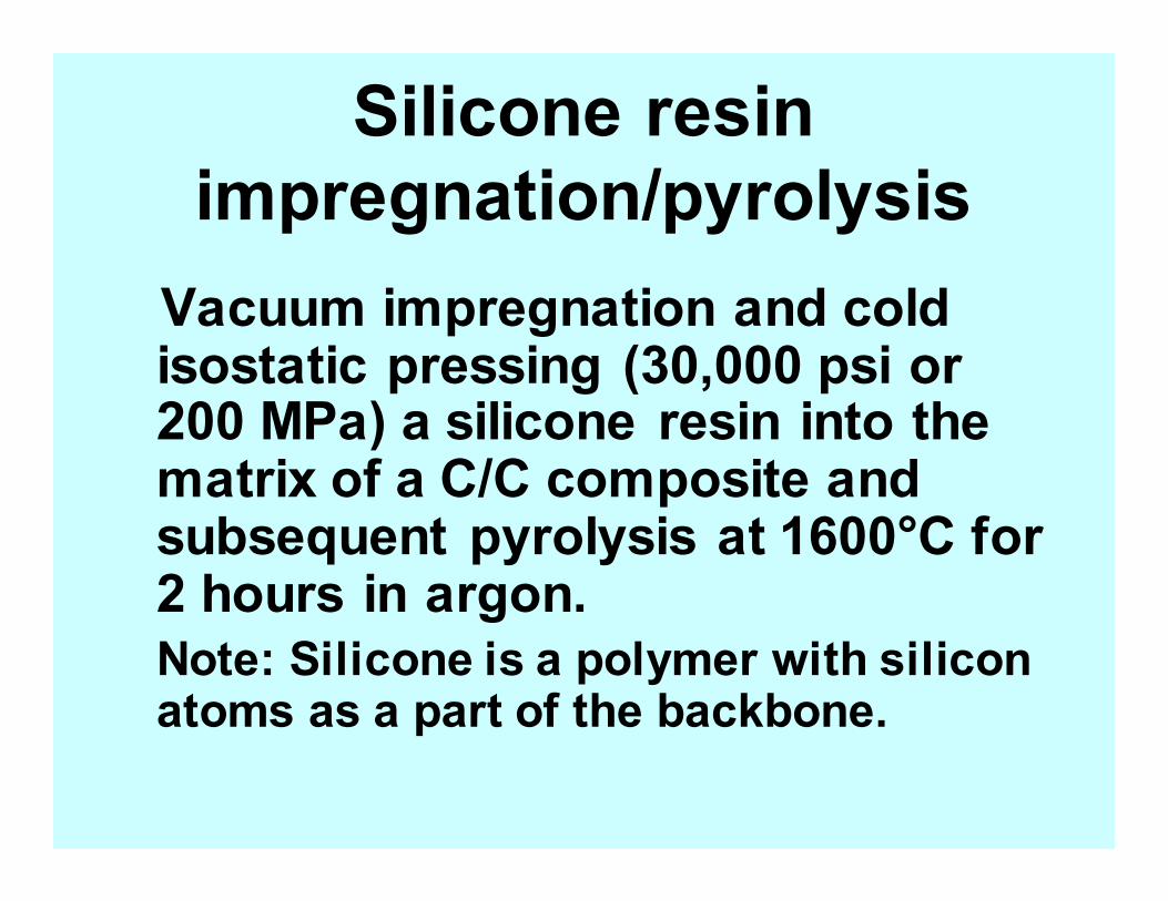
Silicone resin
impregnation/pyrolysis
Vacuum impregnation and cold isostatic pressing (30,000 psi or 200 MPa) a silicone resin into the matrix of a C/C composite and subsequent pyrolysis at 1600°C for 2 hours in argon.
Note: Silicone is a polymer with silicon atoms as a part of the backbone.
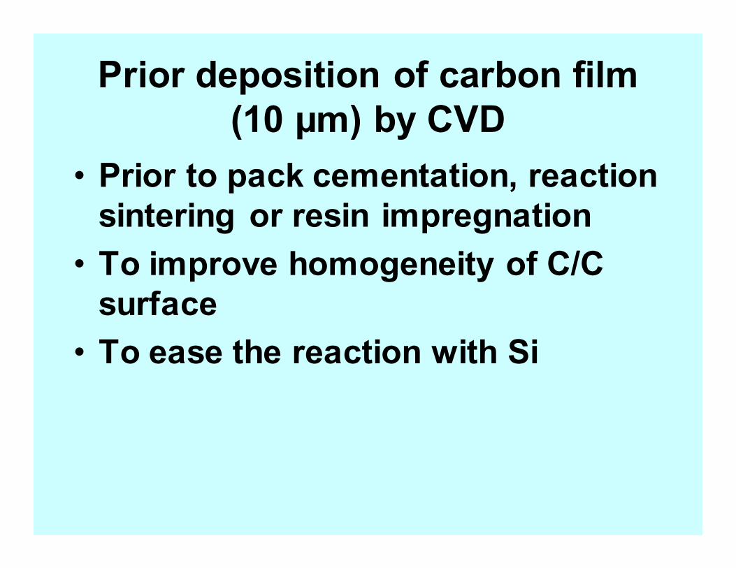
Prior deposition of carbon film
(10 µm) by CVD
• Prior to pack cementation, reaction
sintering or resin impregnation
• To improve homogeneity of C/C
surface
• To ease the reaction with Si
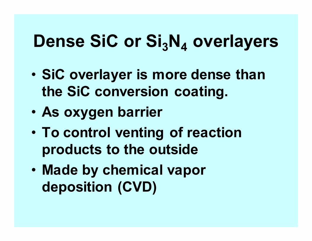
Dense SiC or Si3N4 overlayers
• SiC overlayer is more dense than
the SiC conversion coating.
• As oxygen barrier
• To control venting of reaction
products to the outside
• Made by chemical vapor
deposition (CVD)
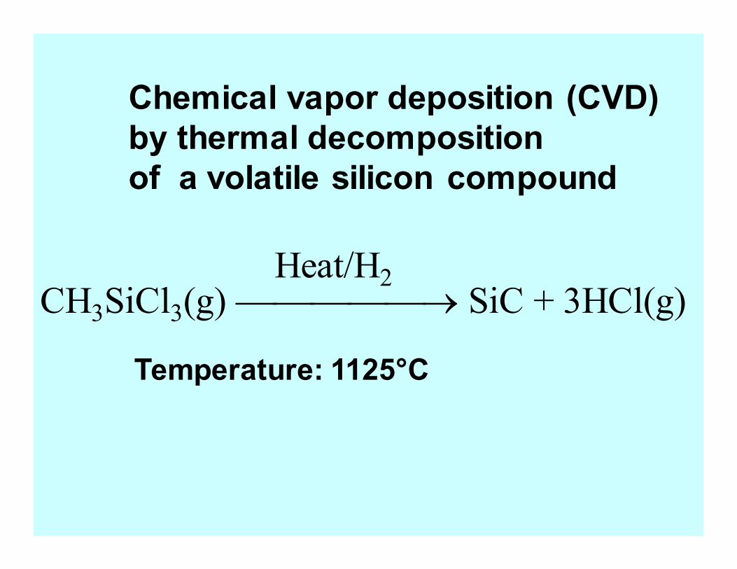
CH3SiCl3(g) → SiC + 3HCl(g) Heat/H2
Chemical vapor deposition (CVD)
by thermal decomposition
of a volatile silicon compound
Temperature: 1125°C
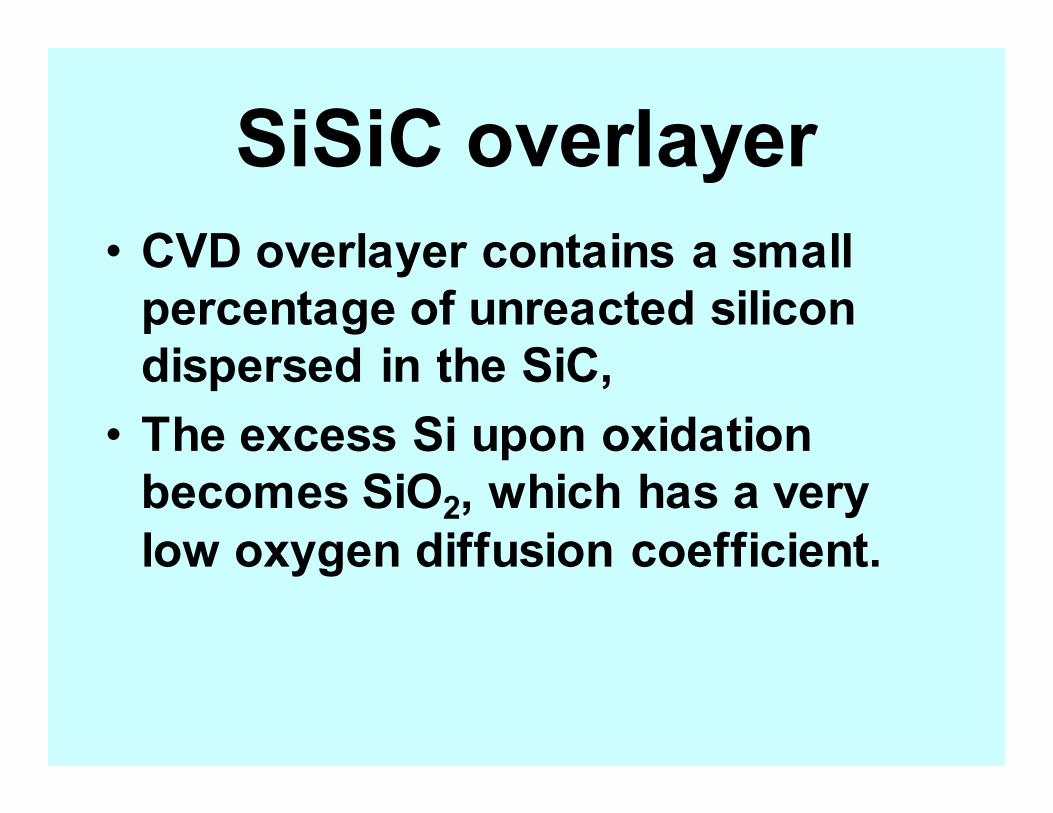
SiSiC overlayer
• CVD overlayer contains a small
percentage of unreacted silicon
dispersed in the SiC,
• The excess Si upon oxidation
becomes SiO2, which has a very
low oxygen diffusion coefficient.
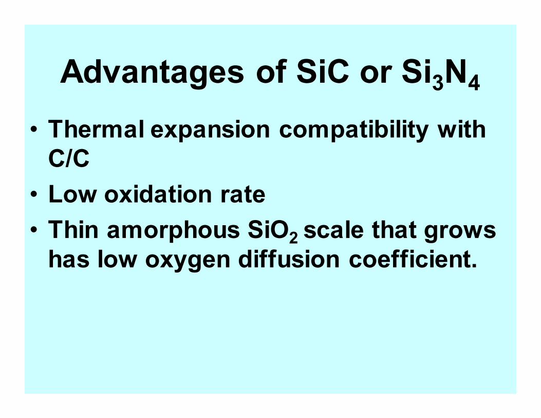
Advantages of SiC or Si3N4
• Thermal expansion compatibility with
C/C
• Low oxidation rate
• Thin amorphous SiO2 scale that grows
has low oxygen diffusion coefficient.
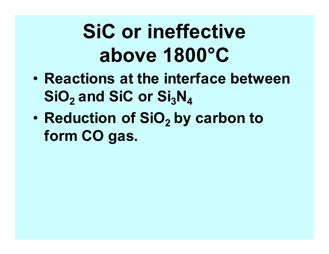
SiC or ineffective
above 1800°C • Reactions at the interface between
SiO2 and SiC or Si3N4
• Reduction of SiO2 by carbon to
form CO gas.
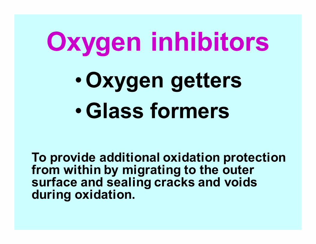
Oxygen inhibitors
•Oxygen getters
•Glass formers
To provide additional oxidation protection from within by migrating to the outer surface and sealing cracks and voids during oxidation.
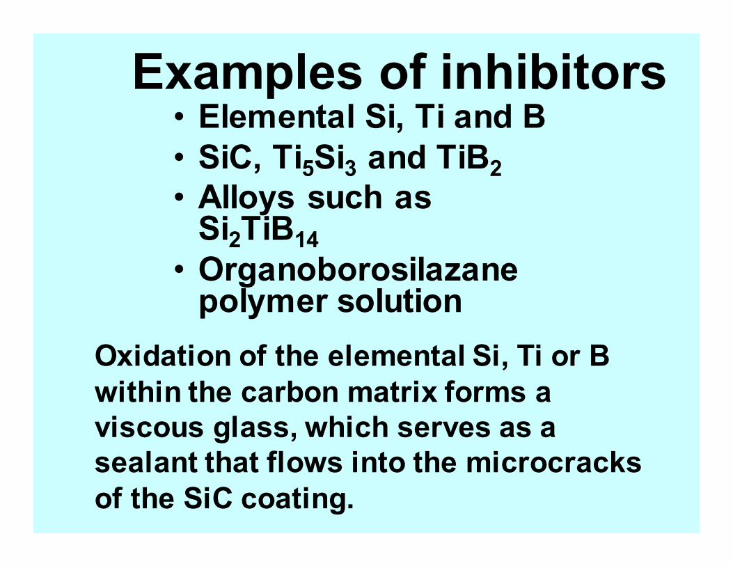
Examples of inhibitors • Elemental Si, Ti and B
• SiC, Ti5Si3 and TiB2
• Alloys such as Si2TiB14
• Organoborosilazane polymer solution
Oxidation of the elemental Si, Ti or B
within the carbon matrix forms a
viscous glass, which serves as a
sealant that flows into the microcracks
of the SiC coating.
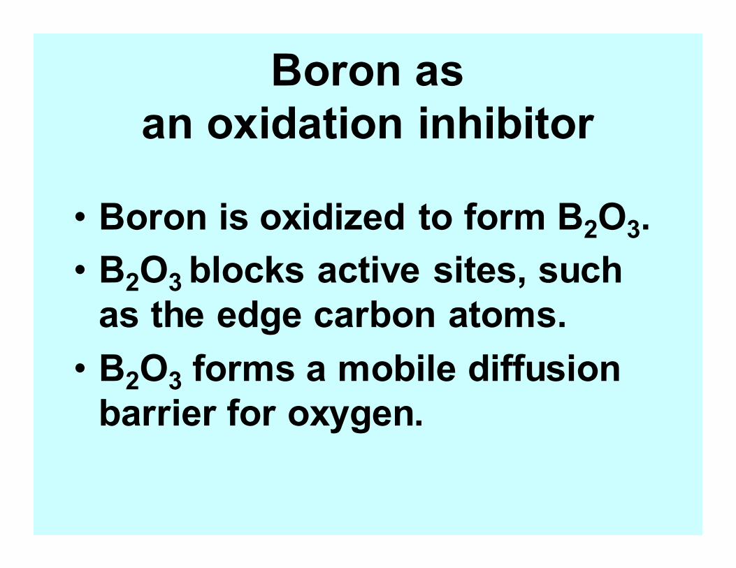
Boron as
an oxidation inhibitor
• Boron is oxidized to form B2O3.
• B2O3 blocks active sites, such
as the edge carbon atoms.
• B2O3 forms a mobile diffusion
barrier for oxygen.
Oxidation rate
Rate of weight loss
Inhibition factor
Ratio of oxidation rate of
untreated carbon to that
of the treated carbon
Incorporating particulate fillers in the resin or pitch
(i) prior to prepregging. during lay-up and
(ii) during densification cycles.
Method of introducing oxidation
inhibitors to the carbon matrix
Glassy sealants
• Glazes comprising mainly silicates (SiOx)
and borates (B2O3).
• Glaze can be filled with SiC particles
• Particularly important if the SiC conversion
coating is porous
• Glaze fills microcracks in the dense
overlayer
Application of a glassy sealant on top of
the SiC conversion coating mainly by
slurry brush-on, so that the sealants melt,
fill voids and stop oxygen diffusion, and, in
some cases, act as oxygen getters.
Effectiveness of borate sealants
• Borates wet C and SiC quite well
• Borates cannot be used above 1200°C due to volatilization
• Borates have poor moisture resistance due to hydrolysis, which results in swelling and crumbling
• Borate has a tendency to galvanically corrode SiC coatings at high temperatures
Modified borate sealants
• The problems of borate can be alleviated by using multicomponent systems such as 10TiO2.20SiO2.70B2O3 .
• TiO2 has a high solubility in B2O3 and is used to prevent the volatilization of B2O3 and increase the viscosity.
• SiO2 acts to increase the moisture resistance, reduce B2O3 volatility, increase viscosity and prevent corrosion of SiC by B2O3.
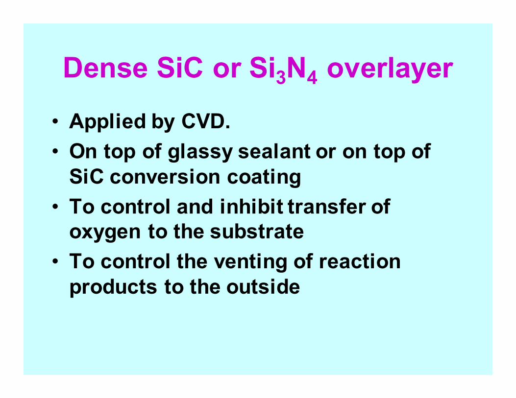
Dense SiC or Si3N4 overlayer
• Applied by CVD.
• On top of glassy sealant or on top of
SiC conversion coating
• To control and inhibit transfer of
oxygen to the substrate
• To control the venting of reaction
products to the outside
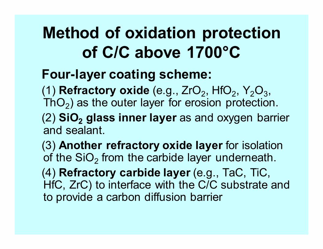
Method of oxidation protection
of C/C above 1700°C
Four-layer coating scheme:
(1) Refractory oxide (e.g., ZrO2, HfO2, Y2O3, ThO2) as the outer layer for erosion protection.
(2) SiO2 glass inner layer as and oxygen barrier and sealant.
(3) Another refractory oxide layer for isolation of the SiO2 from the carbide layer underneath.
(4) Refractory carbide layer (e.g., TaC, TiC, HfC, ZrC) to interface with the C/C substrate and to provide a carbon diffusion barrier
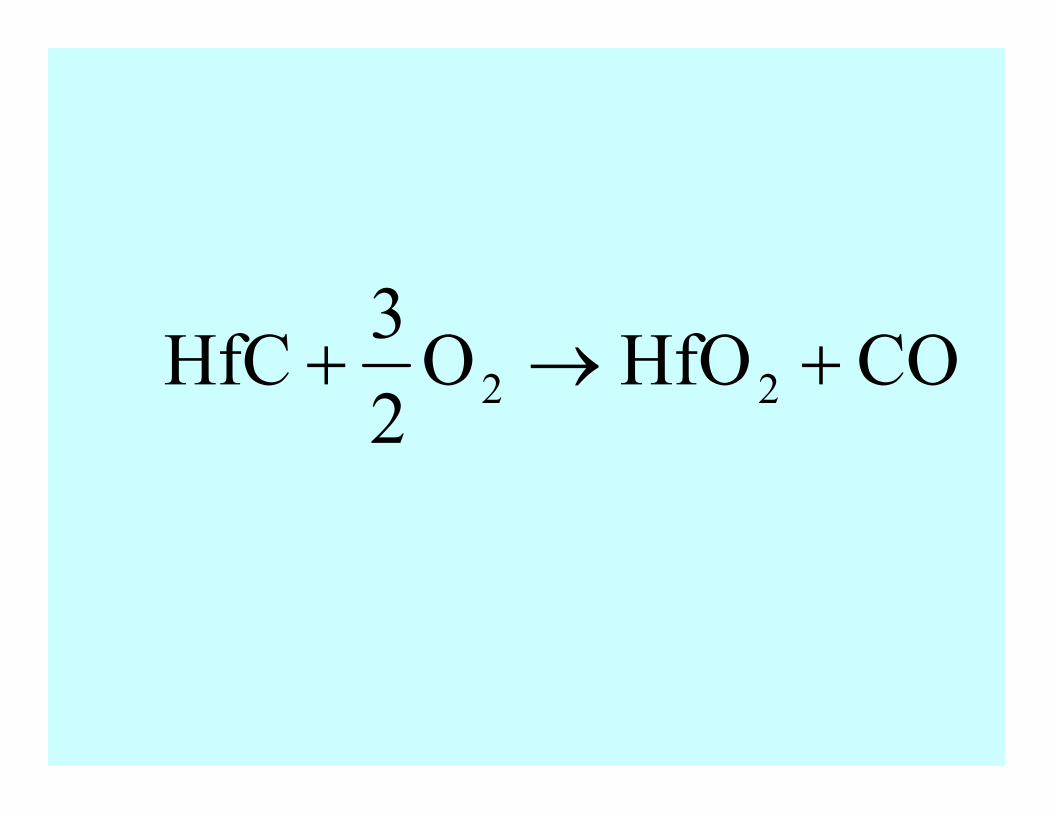
COHfOO2
3HfC 22 +→+
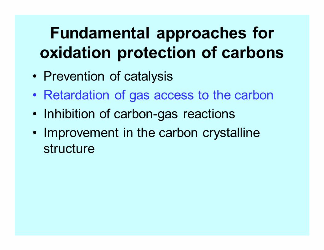
Fundamental approaches for
oxidation protection of carbons
• Prevention of catalysis
• Retardation of gas access to the carbon
• Inhibition of carbon-gas reactions
• Improvement in the carbon crystalline
structure
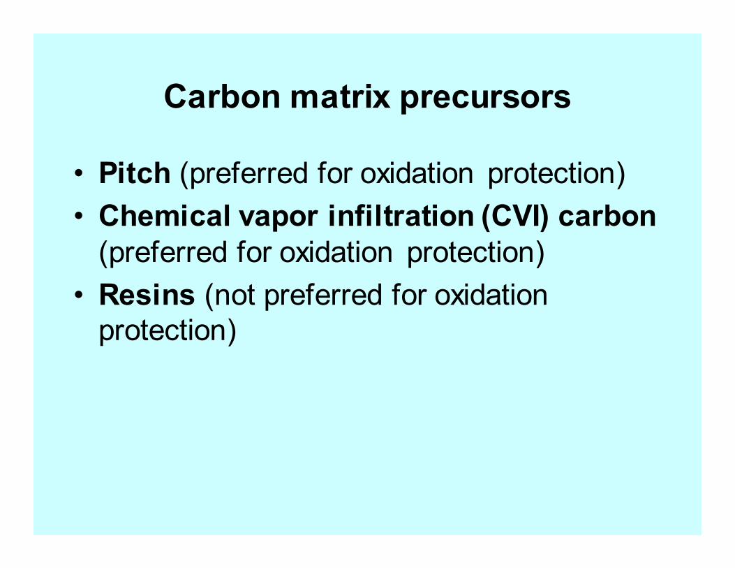
Carbon matrix precursors
• Pitch (preferred for oxidation protection)
• Chemical vapor infiltration (CVI) carbon
(preferred for oxidation protection)
• Resins (not preferred for oxidation
protection)
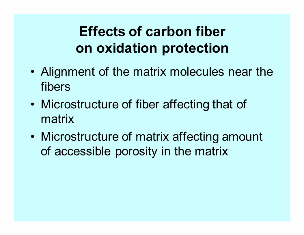
Effects of carbon fiber
on oxidation protection
• Alignment of the matrix molecules near the
fibers
• Microstructure of fiber affecting that of
matrix
• Microstructure of matrix affecting amount
of accessible porosity in the matrix
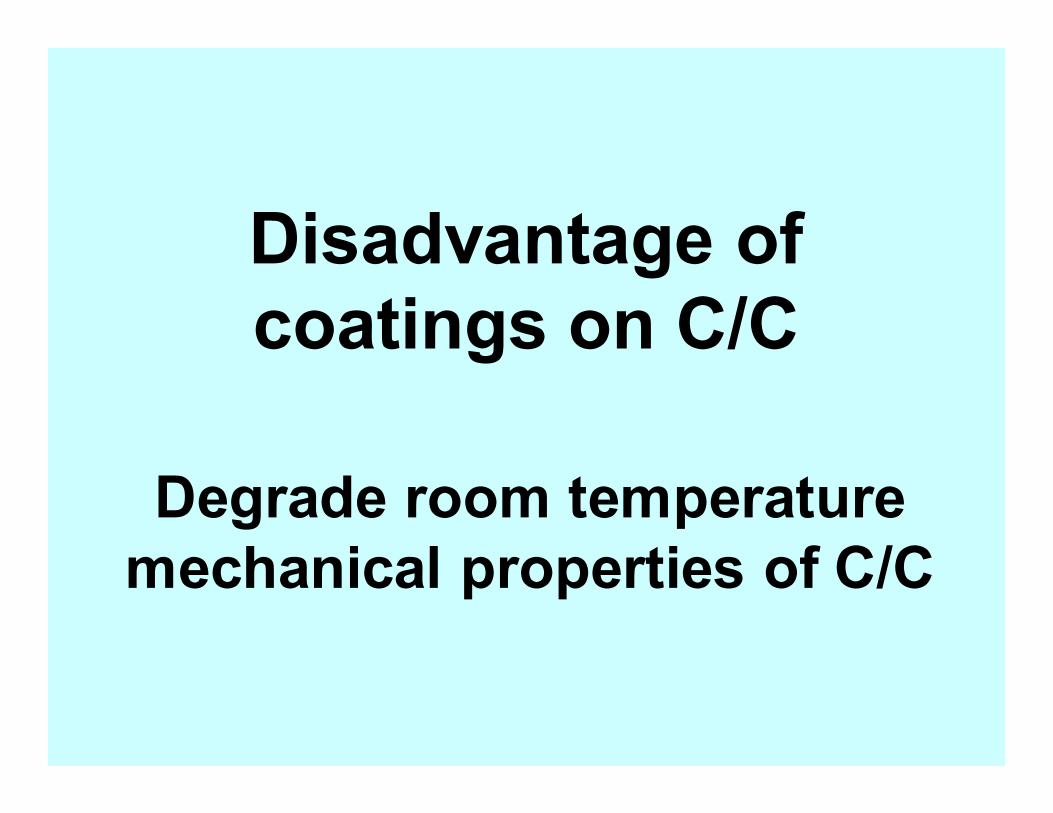
Disadvantage of
coatings on C/C
Degrade room temperature
mechanical properties of C/C
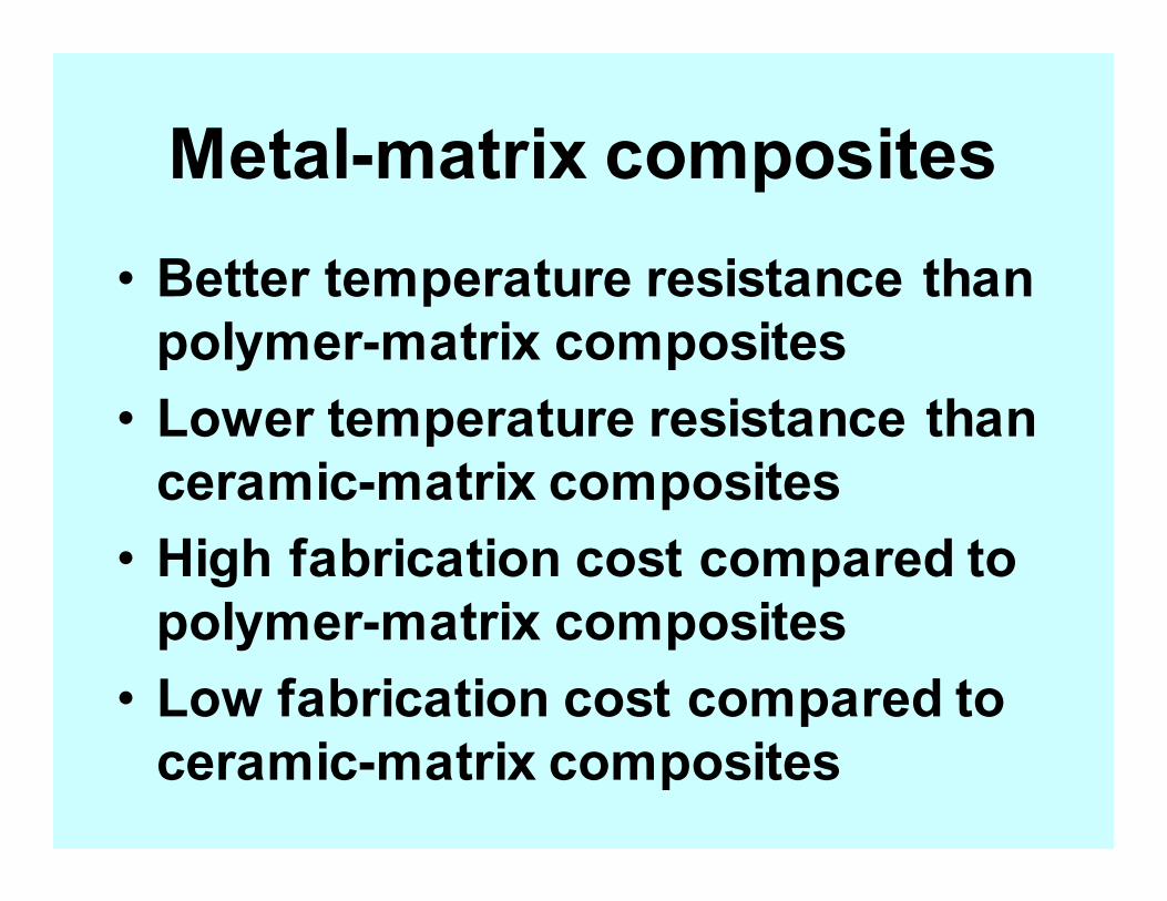
Metal-matrix composites
• Better temperature resistance than
polymer-matrix composites
• Lower temperature resistance than
ceramic-matrix composites
• High fabrication cost compared to
polymer-matrix composites
• Low fabrication cost compared to
ceramic-matrix composites
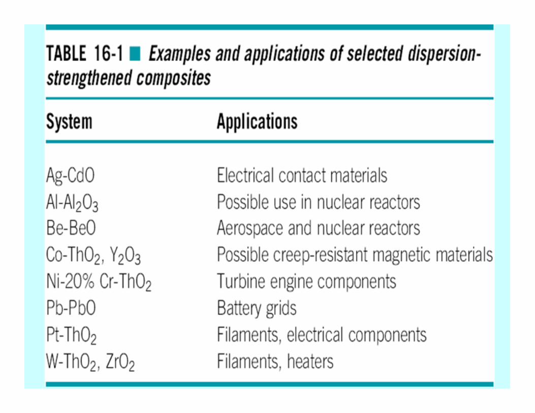
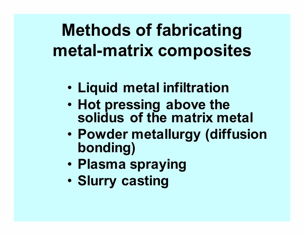
Methods of fabricating
metal-matrix composites
• Liquid metal infiltration
• Hot pressing above the solidus of the matrix metal
• Powder metallurgy (diffusion bonding)
• Plasma spraying
• Slurry casting
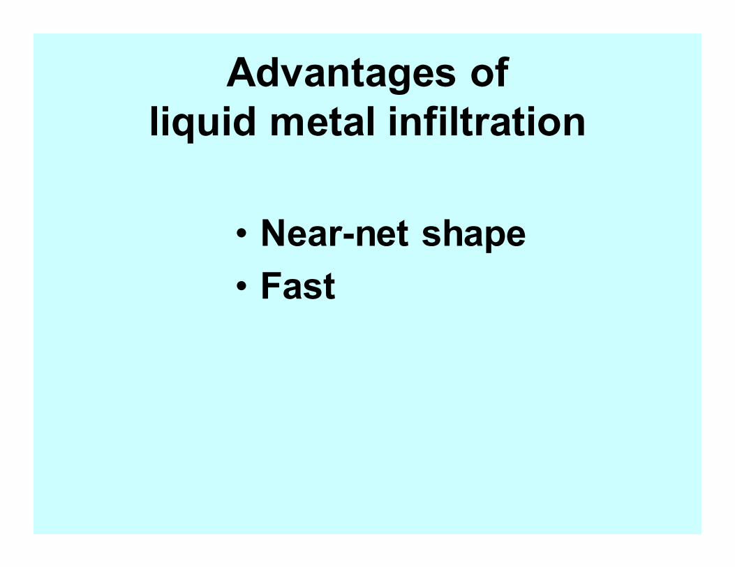
Advantages of
liquid metal infiltration
• Near-net shape
• Fast
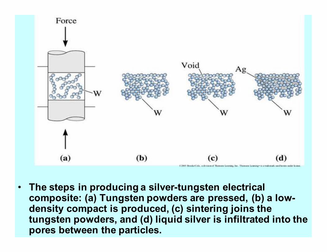
• The steps in producing a silver-tungsten electrical composite: (a) Tungsten powders are pressed, (b) a low-density compact is produced, (c) sintering joins the tungsten powders, and (d) liquid silver is infiltrated into the pores between the particles.
©2003 Brooks/Cole, a division of Thomson Learning, Inc. Thomson Learning™ is a trademark used herein under license.
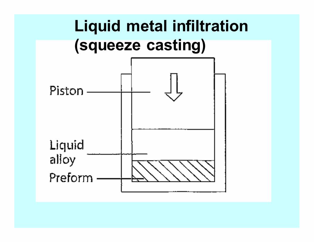
Liquid metal infiltration
(squeeze casting)
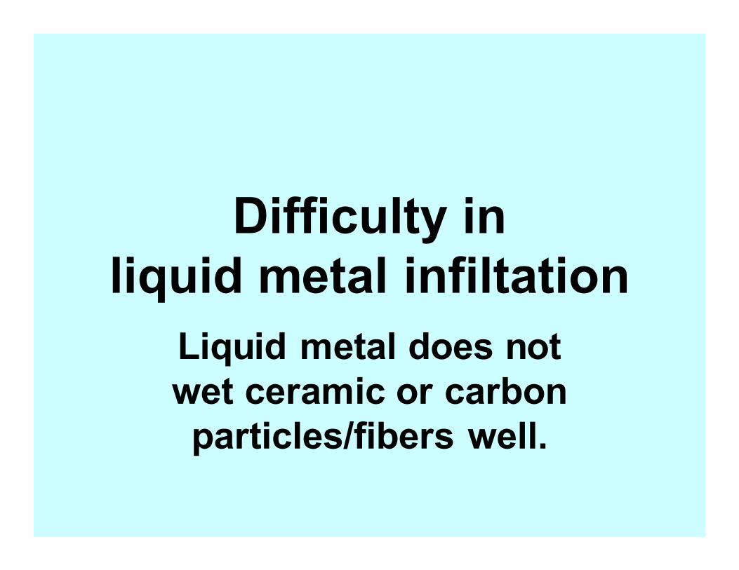
Difficulty in
liquid metal infiltation
Liquid metal does not
wet ceramic or carbon
particles/fibers well.
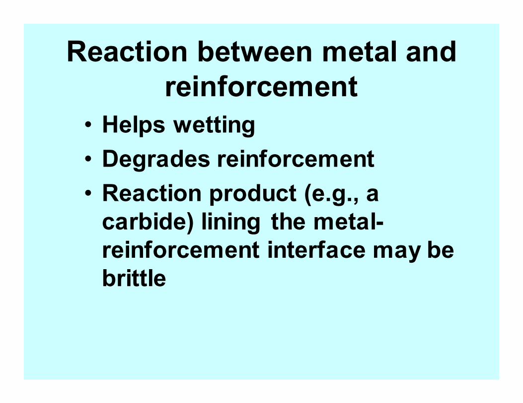
Reaction between metal and
reinforcement
• Helps wetting
• Degrades reinforcement
• Reaction product (e.g., a
carbide) lining the metal-
reinforcement interface may be
brittle
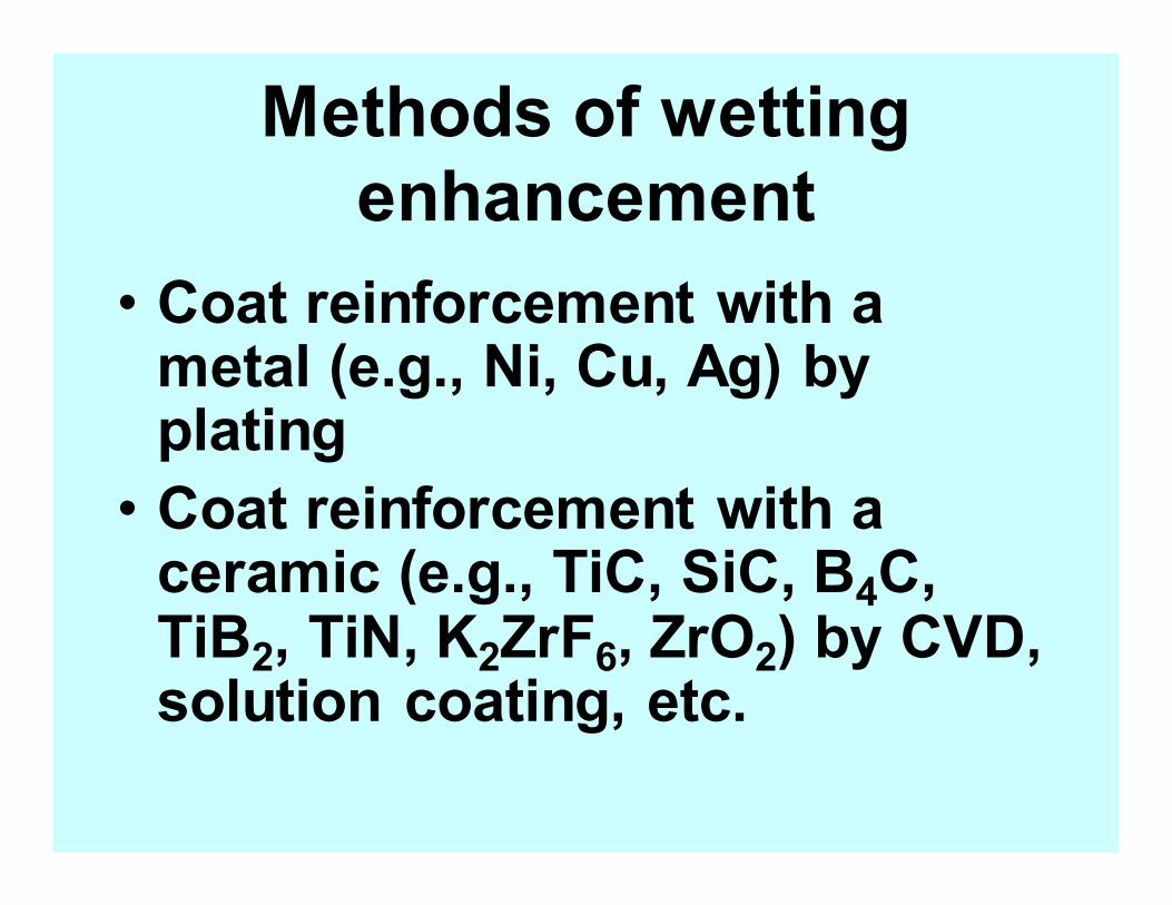
Methods of wetting
enhancement
• Coat reinforcement with a metal (e.g., Ni, Cu, Ag) by plating
• Coat reinforcement with a ceramic (e.g., TiC, SiC, B4C, TiB2, TiN, K2ZrF6, ZrO2) by CVD, solution coating, etc.
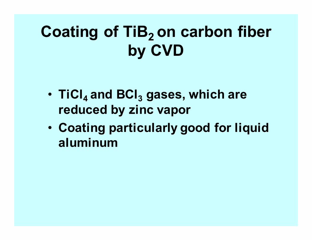
Coating of TiB2 on carbon fiber
by CVD
• TiCl4 and BCl3 gases, which are
reduced by zinc vapor
• Coating particularly good for liquid
aluminum
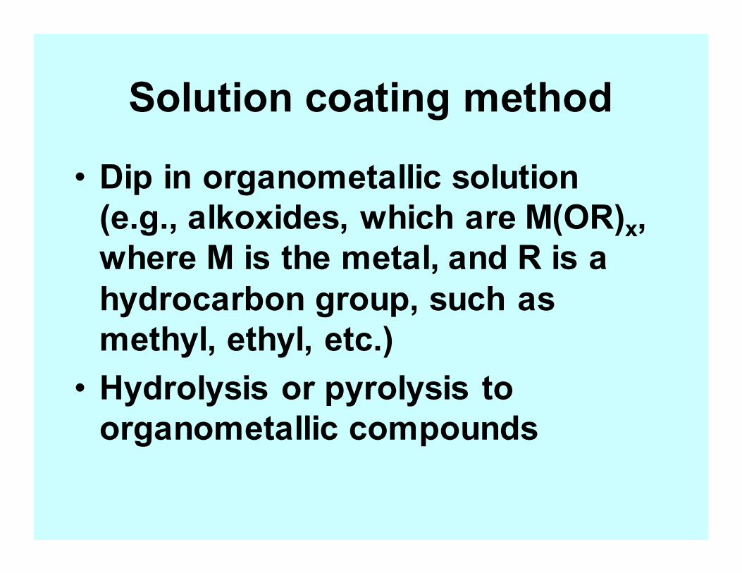
Solution coating method
• Dip in organometallic solution
(e.g., alkoxides, which are M(OR)x,
where M is the metal, and R is a
hydrocarbon group, such as
methyl, ethyl, etc.)
• Hydrolysis or pyrolysis to
organometallic compounds
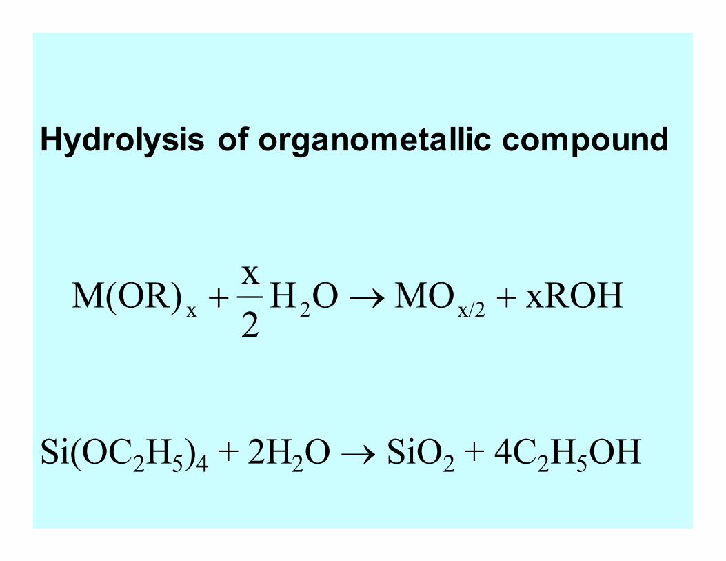
xROHMOOH2
xM(OR) x/22x +→+
Si(OC2H5)4 + 2H2O → SiO2 + 4C2H5OH
Hydrolysis of organometallic compound
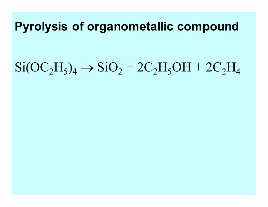
Si(OC2H5)4 → SiO2 + 2C2H5OH + 2C2H4
Pyrolysis of organometallic compound
Powder metallurgy
• Near-net shape
• Size limited by the pressure
requirement
Two methods of
powder metallurgy
• Mixture of matrix powder and
reinforcement particles/fibers
• Matrix coated reinforcement
particles/fibers
©2003 Brooks/Cole, a division of Thomson Learning, Inc. Thomson Learning™ is a trademark used herein under license.
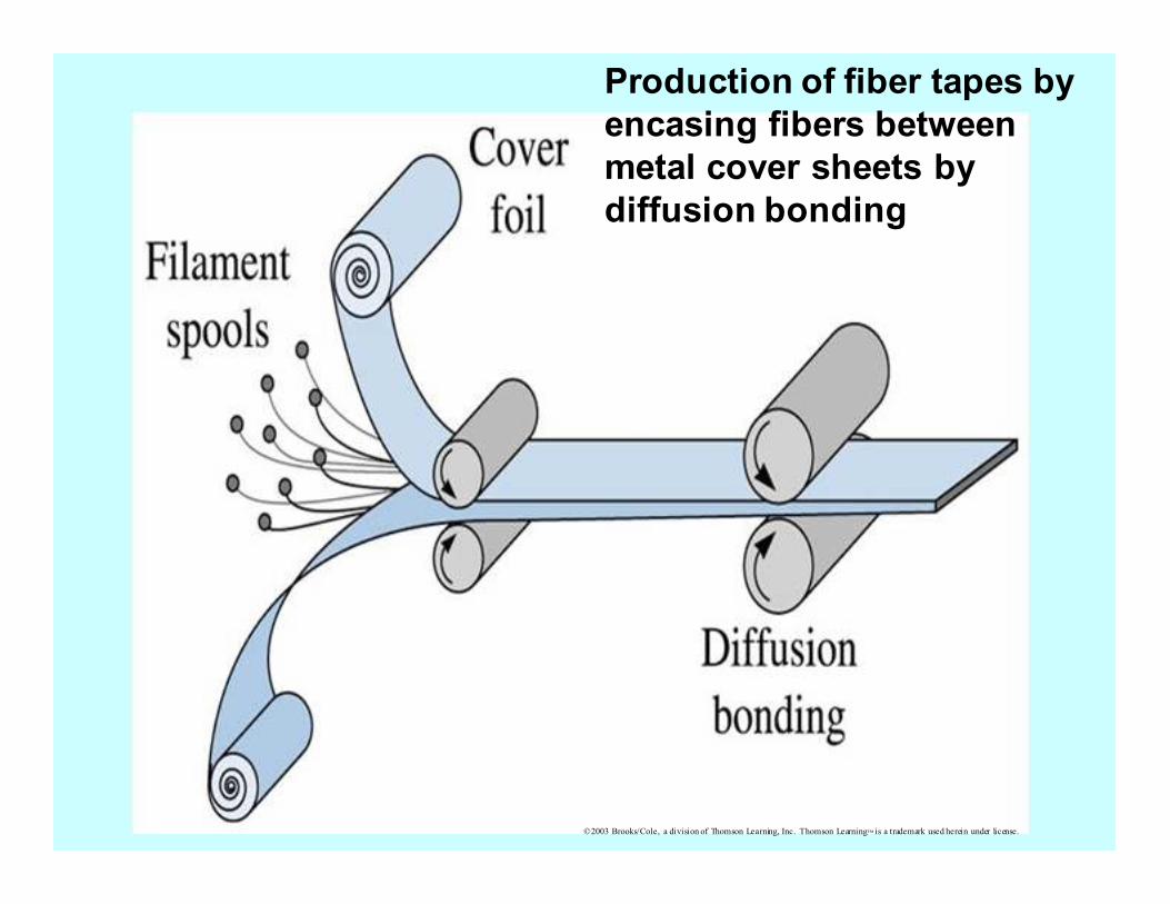
Production of fiber tapes by
encasing fibers between
metal cover sheets by
diffusion bonding
©2003 B
rooks/Cole, a division of Thomson Learning, Inc. Thomson Learning™ is a trademark used herein under license.
Yield
strength
Particulate aluminum-
matrix composite
Aluminum alloys
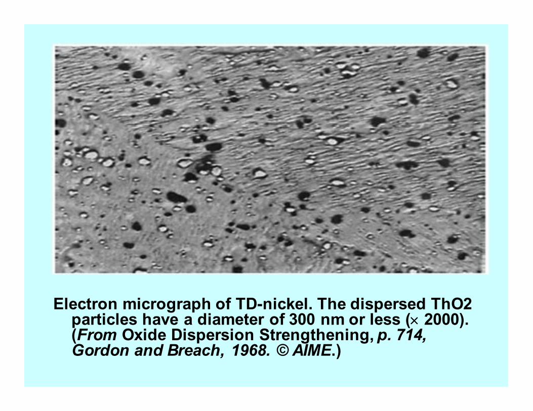
Electron micrograph of TD-nickel. The dispersed ThO2 particles have a diameter of 300 nm or less (×××× 2000). (From Oxide Dispersion Strengthening, p. 714, Gordon and Breach, 1968. © AIME.)
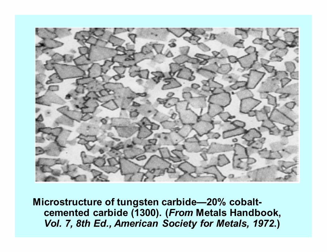
Microstructure of tungsten carbide—20% cobalt-cemented carbide (1300). (From Metals Handbook, Vol. 7, 8th Ed., American Society for Metals, 1972.)
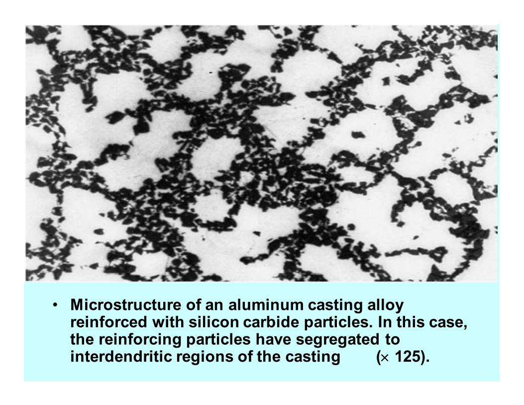
• Microstructure of an aluminum casting alloy reinforced with silicon carbide particles. In this case, the reinforcing particles have segregated to interdendritic regions of the casting (×××× 125).
©2003 Brooks/Cole, a division of Thomson Learning, Inc. Thomson Learning™ is a trademark used herein under license.
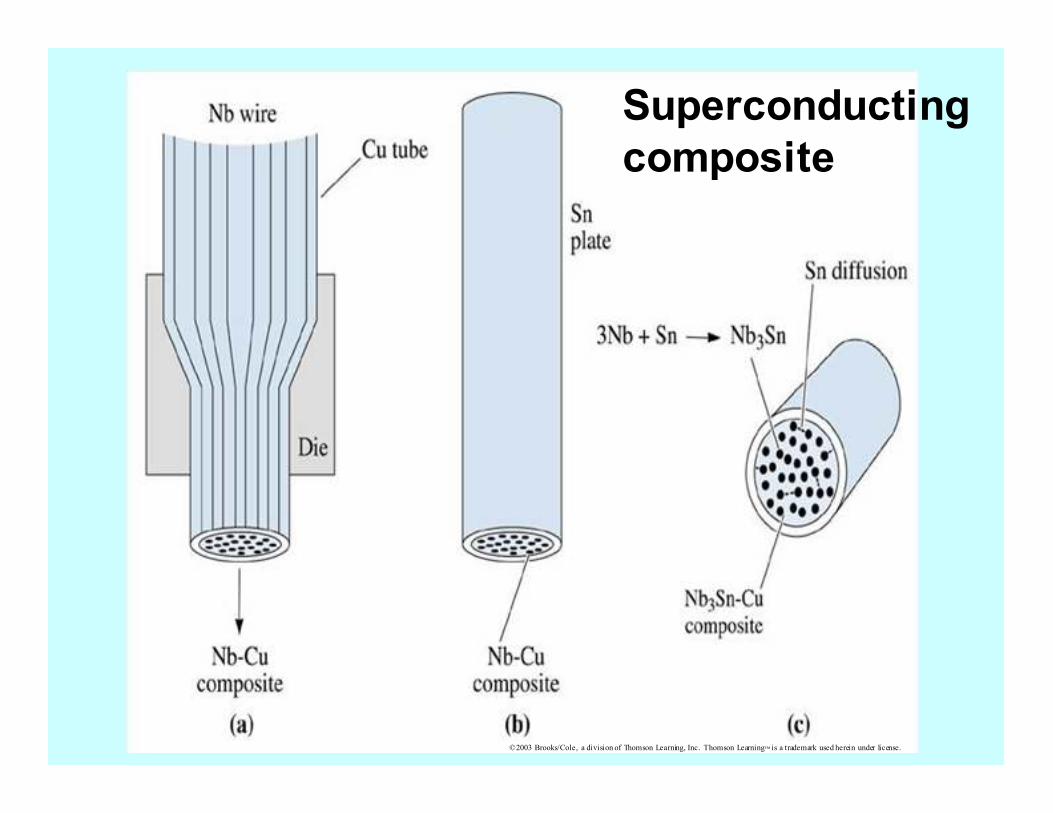
Superconducting
composite
©2003 Brooks/Cole, a division of Thomson Learning, Inc. Thomson Learning™ is a trademark used herein under license.
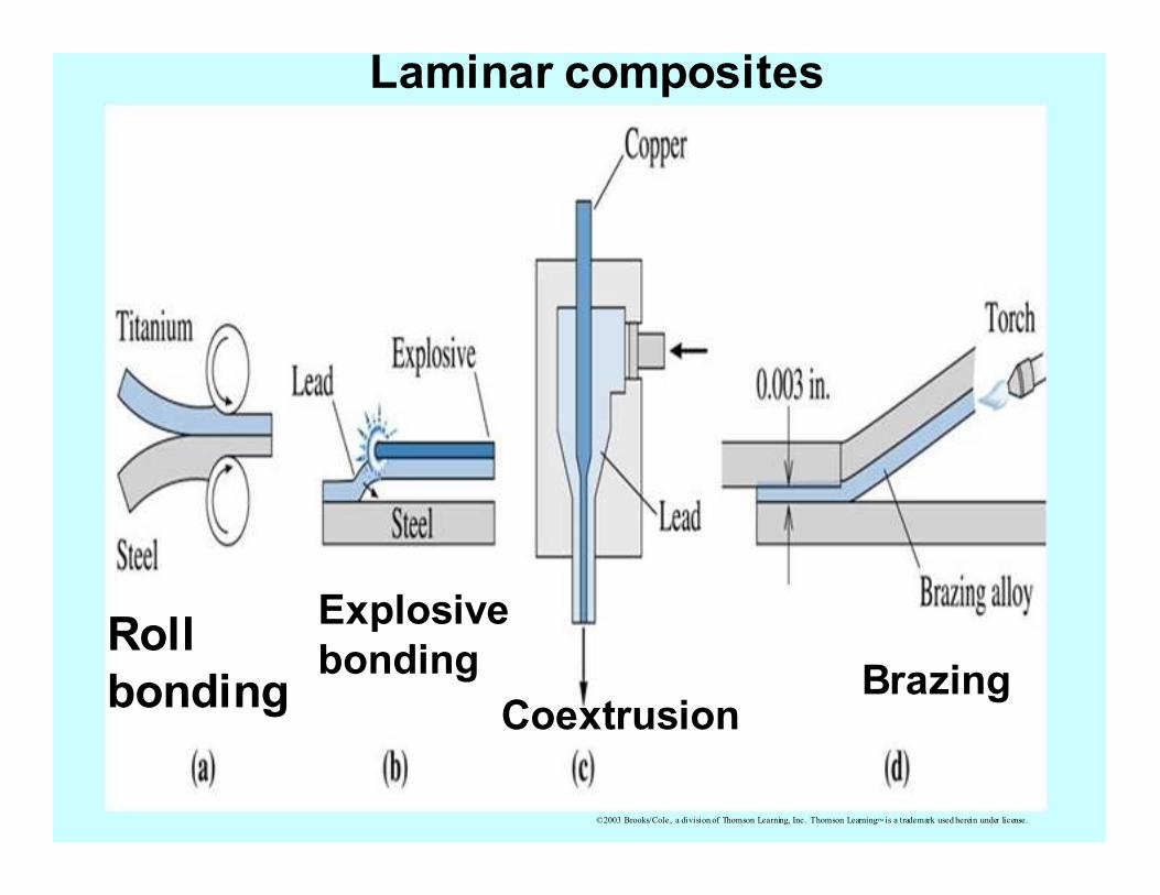
Laminar composites
Roll
bonding
Explosive
bonding
Coextrusion Brazing
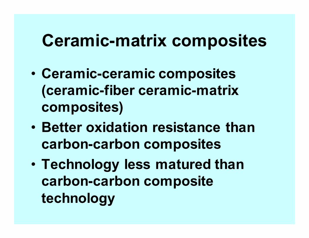
Ceramic-matrix composites
• Ceramic-ceramic composites
(ceramic-fiber ceramic-matrix
composites)
• Better oxidation resistance than
carbon-carbon composites
• Technology less matured than
carbon-carbon composite
technology
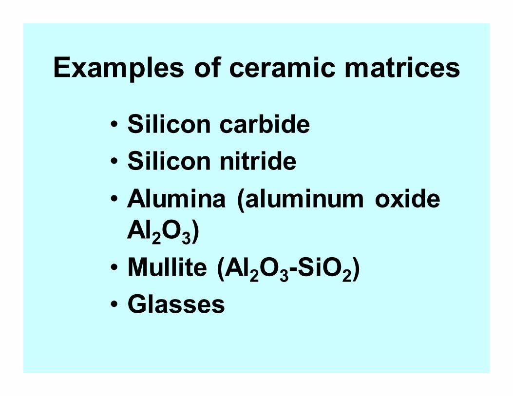
Examples of ceramic matrices
• Silicon carbide
• Silicon nitride
• Alumina (aluminum oxide
Al2O3)
• Mullite (Al2O3-SiO2)
• Glasses