Embed Size (px)
DESCRIPTION
circuit
Citation preview
1
2.1 Branch-Current Analysis
2.2 Mesh Analysis
2.3 Nodal Analysis
2.4 Mesh with Current Sources
2.5 Nodal with Voltage Sources
2.6 Bridge Network
Chapter 2: Circuit Analysis
2
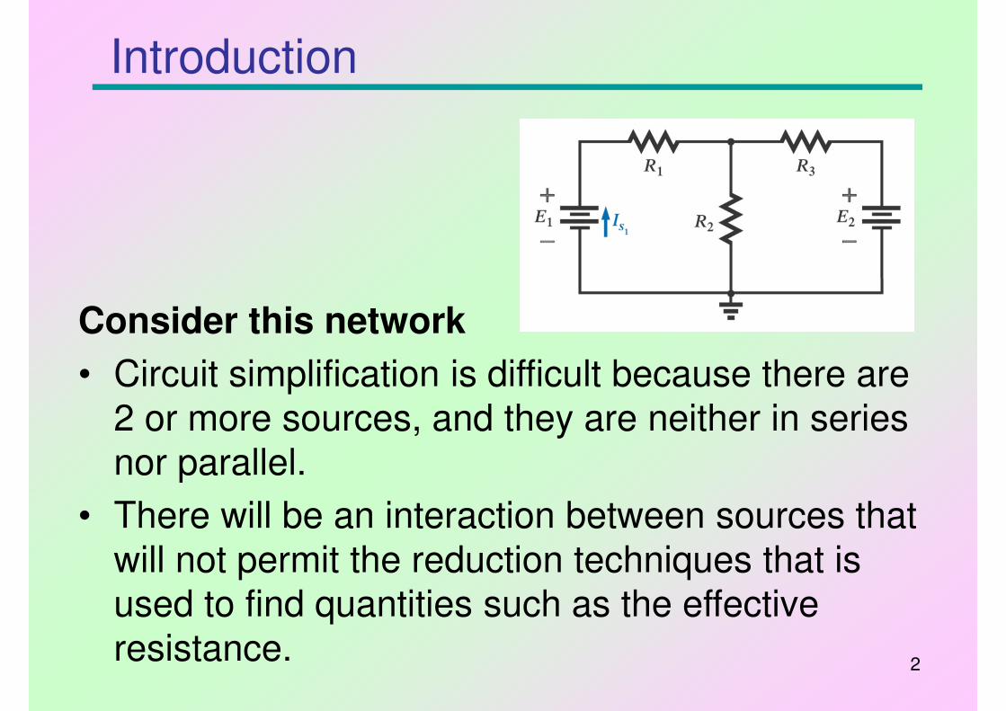
Introduction
Consider this network
• Circuit simplification is difficult because there are
2 or more sources, and they are neither in series nor parallel.
• There will be an interaction between sources that
will not permit the reduction techniques that is used to find quantities such as the effective
resistance.
3
Steps required for Branch-Current Analysis: -
1. Assign a distinct current of arbitrary direction to
each branch of the circuit.
2. Add the polarities for each voltage drop across resistor.
3. Apply KVL for each mesh.
4. Apply KCL to a node that includes all the branch currents.
5. Solve the equations for branch currents.
2.1 Branch-Current Analysis
4
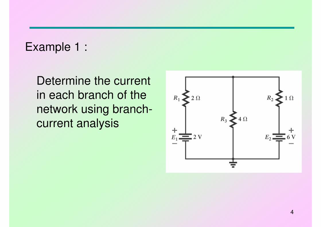
Example 1 :
Determine the current
in each branch of the network using branch-
current analysis
5
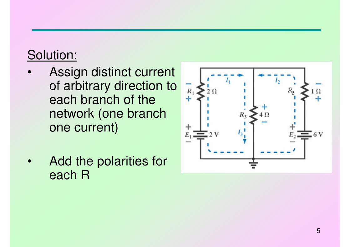
Solution:
• Assign distinct current of arbitrary direction to each branch of the network (one branch one current)
• Add the polarities for each R
6
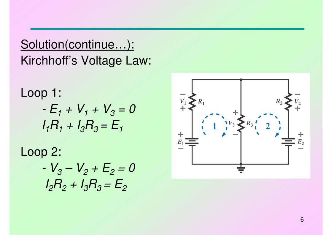
Solution(continue…):
Kirchhoff’s Voltage Law:
Loop 1:
- E1 + V1 + V3 = 0
I1R1 + I3R3 = E1
Loop 2:
- V3 – V2 + E2 = 0
I2R2 + I3R3 = E2
7
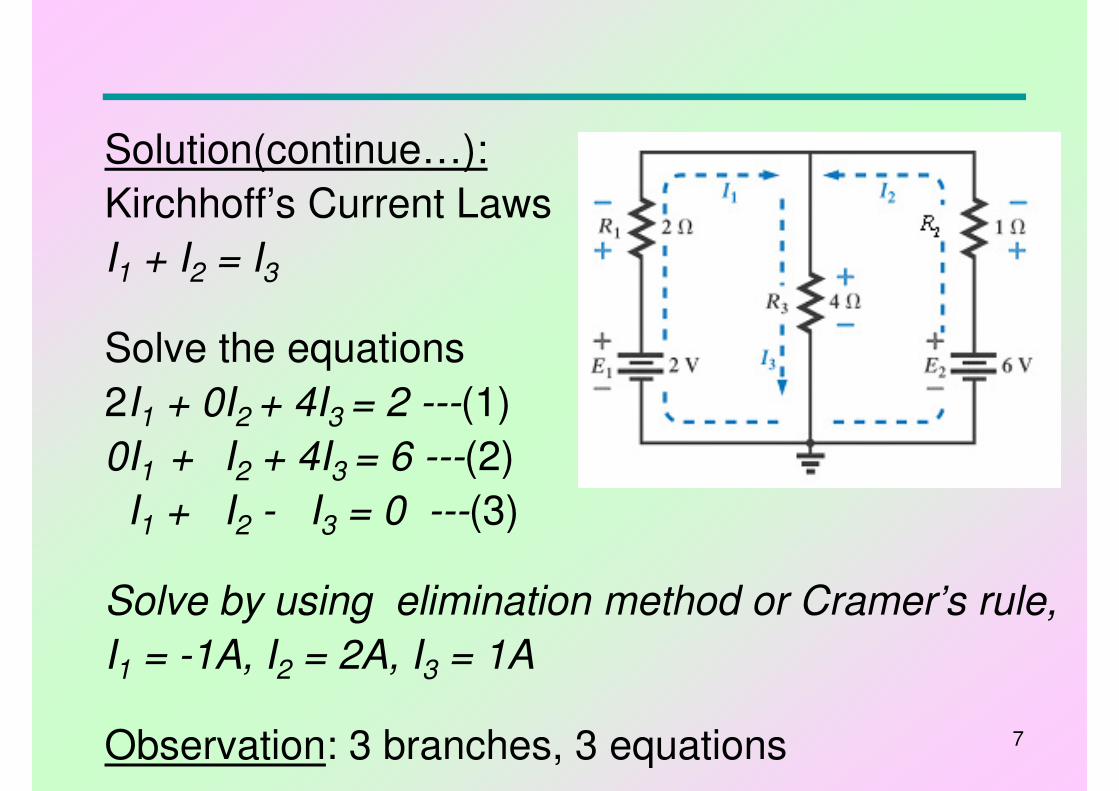
Solution(continue…):
Kirchhoff’s Current Laws
I1 + I2 = I3
Solve the equations
2I1 + 0I2 + 4I3 = 2 ---(1)
0I1 + I2 + 4I3 = 6 ---(2)
I1 + I2 - I3 = 0 ---(3)
Solve by using elimination method or Cramer’s rule,
I1 = -1A, I2 = 2A, I3 = 1A
Observation: 3 branches, 3 equations
8
• Mesh Analysis – defines a unique array of currents (Mesh or Loop current) to the network.
• Steps required for Mesh Analysis: -
1. Assign current in clockwise direction to each closed loop of network.
2. Insert polarities for each resistor.
3. Apply KVL to each closed loop.
4. Solve the resulting equations.
Note: if a resistor has two or more current passing through it, the netcurrent = the mesh current of the closed loop + mesh currents from other loops in same direction - mesh currents from other loops in opposite direction.
2.2 Mesh Analysis
9
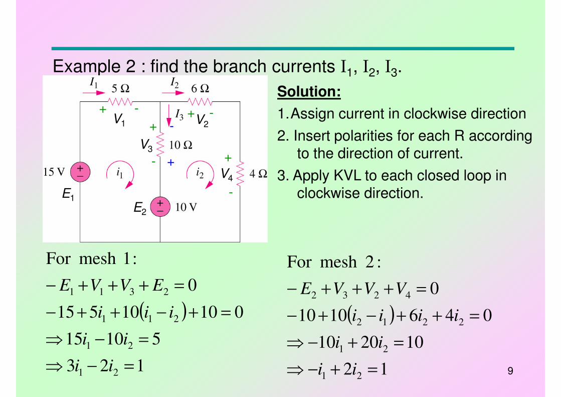
Example 2 : find the branch currents I1, I2, I3.
1.Assign current in clockwise direction
( )
123
51015
01010515
0
:1mesh For
21
21
211
2311
=−⇒
=−⇒
=+−++−
=+++−
ii
ii
iii
EVVE
( )
12
102010
0461010
0
:2mesh For
21
21
2212
4232
=+−⇒
=+−⇒
=++−+−
=+++−
ii
ii
iiii
VVVE
Solution:
+ -
+
-
+ -
+
-
2. Insert polarities for each R according to the direction of current.
3. Apply KVL to each closed loop in clockwise direction.
-
+
E1
V1 V2
V4
V3
E2
10
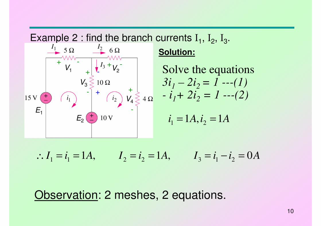
Example 2 : find the branch currents I1, I2, I3.
AiAi 1,1 21 ==
Solution:
+ -
+
-
+ -
+
-
-
+
E1
V1 V2
V4
V3
E2
Solve the equations3i1 – 2i2 = 1 ---(1)
- i1+ 2i2 = 1 ---(2)
AiiIAiIAiI 0,1,1 2132211 =−=====∴
Observation: 2 meshes, 2 equations.
11
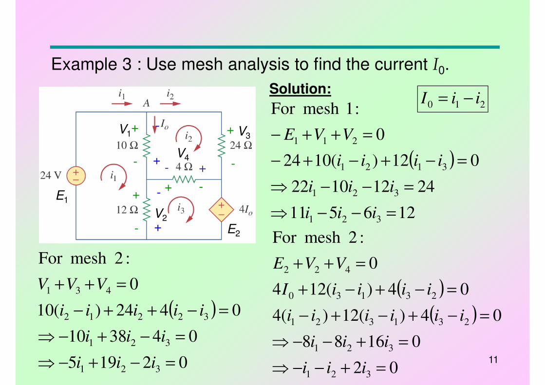
Example 3 : Use mesh analysis to find the current I0.
Solution:
+ -+
-
+
-
-
+
E1
V1
V2
V4
V3
E2
+
-
-
+- +
( )
126511
24121022
012)(1024
0
:1mesh For
321
321
3121
211
=−−⇒
=−−⇒
=−+−+−
=++−
iii
iii
iiii
VVE
( )
02195
043810
0424)(10
0
:2mesh For
321
321
32212
431
=−+−⇒
=−+−⇒
=−++−
=++
iii
iii
iiiii
VVV ( )
( )
02
01688
04)(12)(4
04)(124
0
:2mesh For
321
321
231321
23130
422
=+−−⇒
=+−−⇒
=−+−+−
=−+−+
=++
iii
iii
iiiiii
iiiiI
VVE
210 iiI −=
12
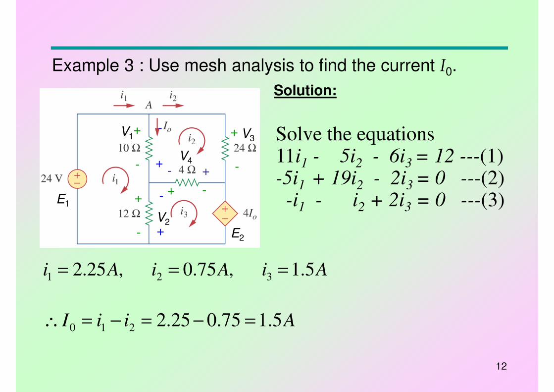
Example 3 : Use mesh analysis to find the current I0.
Solution:
+ -+
-
+
-
-
+
E1
V1
V2
V4
V3
E2
+
-
-
+- +
Solve the equations11i1 - 5i2 - 6i3 = 12 ---(1)-5i1 + 19i2 - 2i3 = 0 ---(2)
-i1 - i2 + 2i3 = 0 ---(3)
AiAiAi 5.1,75.0,25.2 321 ===
AiiI 5.175.025.2210 =−=−=∴
13
2.3 Nodal Analysis• Nodal analysis - provides nodal voltages by using KCL.
• Steps required for Nodal Analysis: -
1. Determine the no. of nodes (junction of 2 or more branches).
2. Select a reference node (Ground), and label all other nodes.
3. Apply KCL at each node (except the reference node).
4. Solve the resulting equations.
Note: A network of N nodes require (N-1) equations to find (N-1) nodal voltages where by the Reference node is eliminated.
14
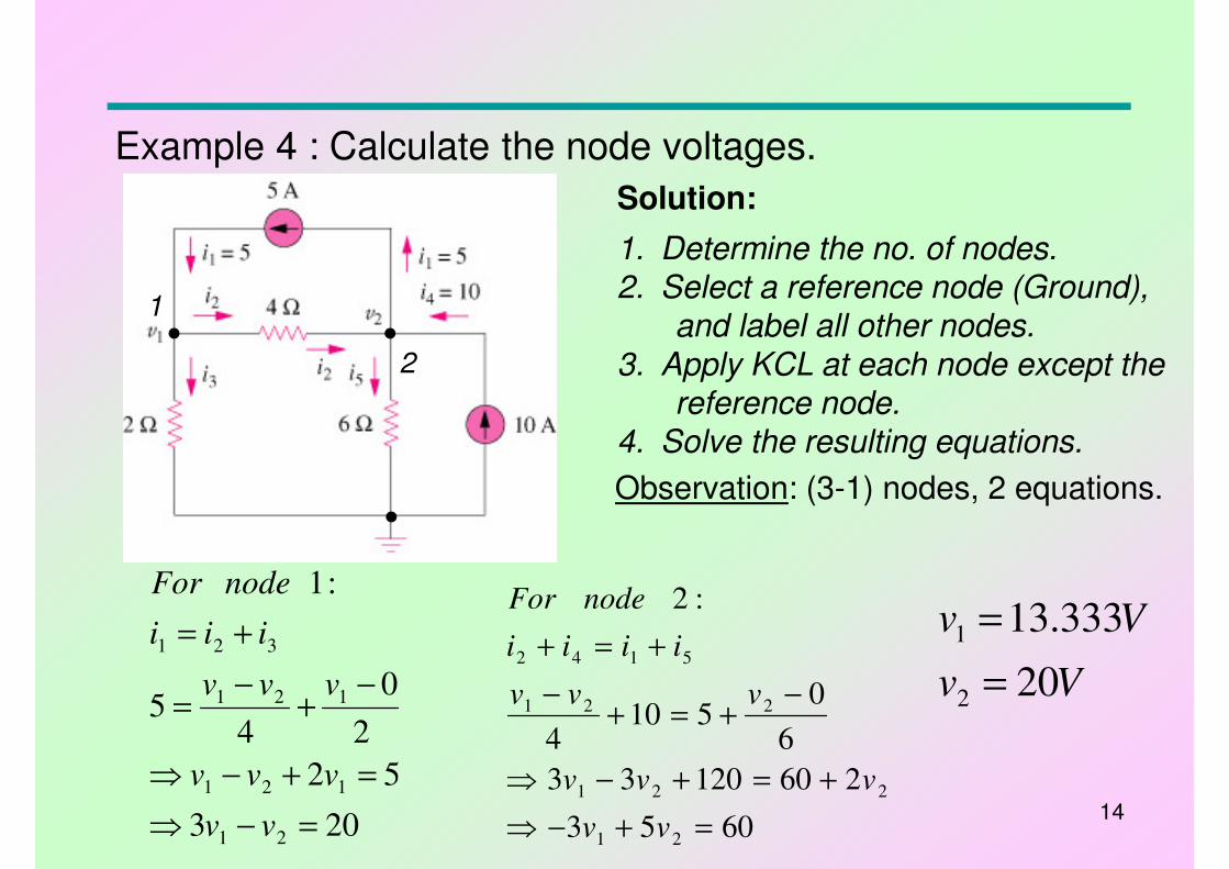
Example 4 : Calculate the node voltages.
1. Determine the no. of nodes.2. Select a reference node (Ground),
and label all other nodes.
3. Apply KCL at each node except the reference node.
4. Solve the resulting equations.
203
52
2
0
45
:1
21
121
121
321
=−⇒
=+−⇒
−+
−=
+=
vv
vvv
vvv
iii
nodeFor
Solution:
6053
26012033
6
0510
4
:2
21
221
221
5142
=+−⇒
+=+−⇒
−+=+
−
+=+
vv
vvv
vvv
iiii
nodeFor
Observation: (3-1) nodes, 2 equations.
Vv
Vv
20
333.13
2
1
=
=
1
2
15
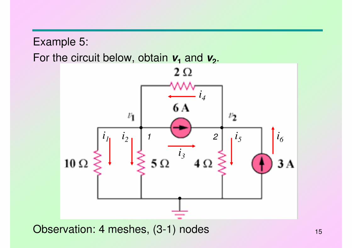
Example 5:
For the circuit below, obtain v1 and v2.
Observation: 4 meshes, (3-1) nodes
i1 i2
i4
i5 i6
i3
1 2
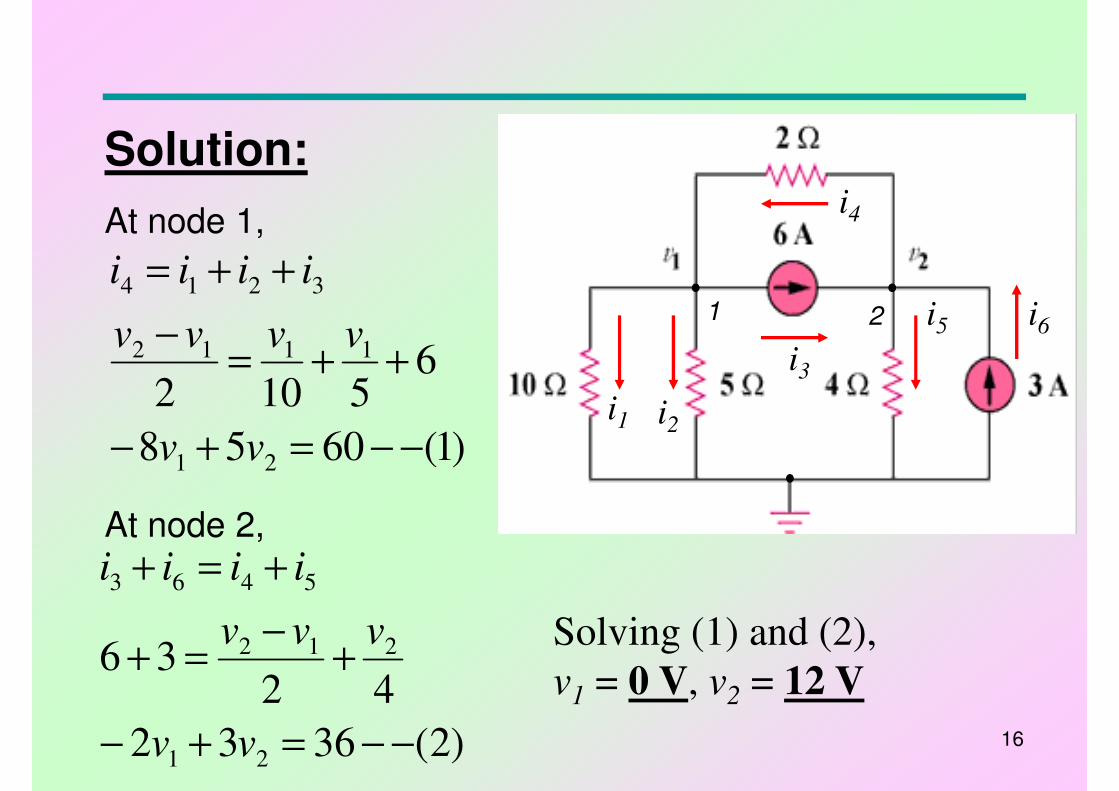
16
At node 1,
At node 2,
)1(6058
65102
21
1112
3214
−−=+−
++=−
++=
vv
vvvv
iiii
Solution:
i1 i2
i4
i5 i6
i3
)2(3632
4236
21
212
5463
−−=+−
+−
=+
+=+
vv
vvv
iiii
Solving (1) and (2),
v1 = 0 V, v2 = 12 V
1 2
17
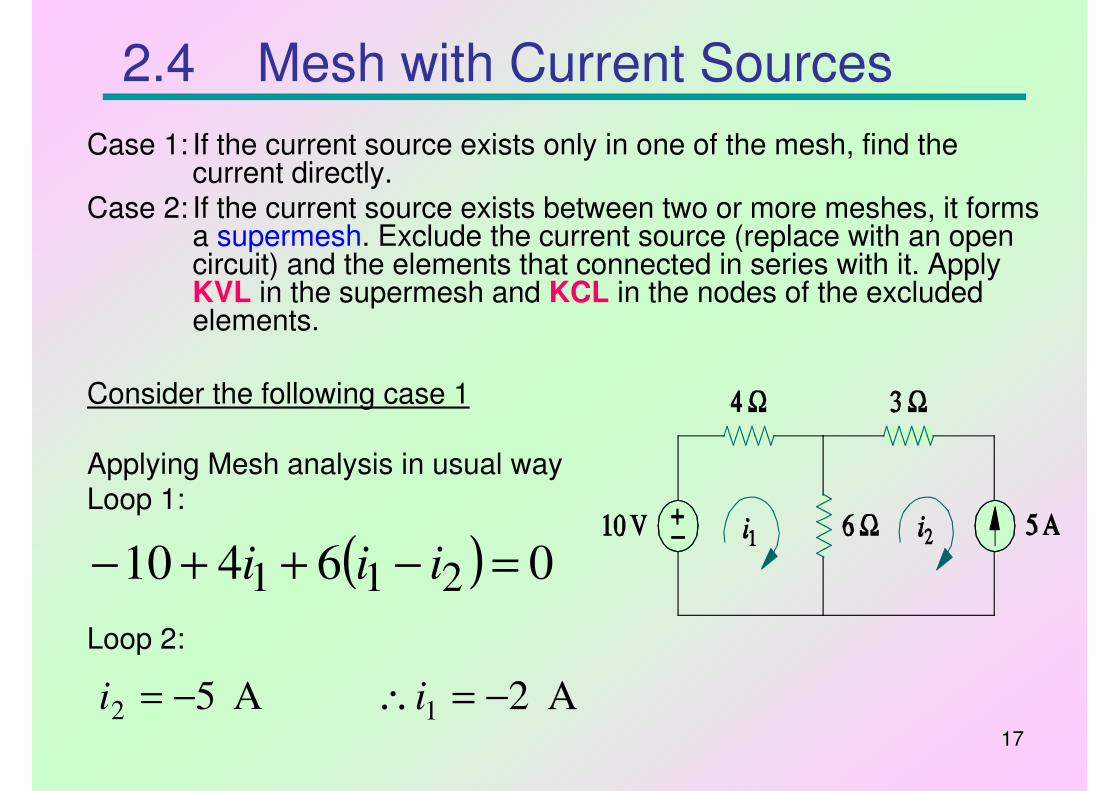
2.4 Mesh with Current Sources
Case 1: If the current source exists only in one of the mesh, find the current directly.
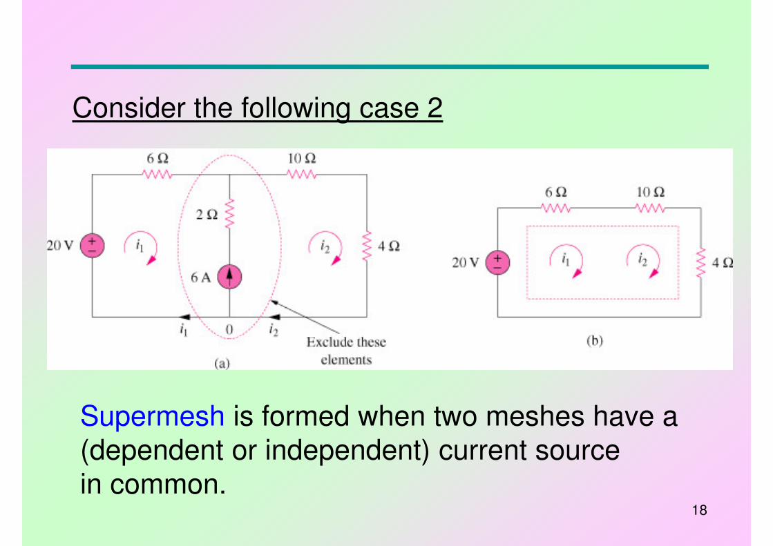
Case 2: If the current source exists between two or more meshes, it forms a supermesh. Exclude the current source (replace with an open circuit) and the elements that connected in series with it. Apply KVL in the supermesh and KCL in the nodes of the excluded elements.
Consider the following case 1
Applying Mesh analysis in usual wayLoop 1:
( ) 06410 211 =−++− iii
Loop 2:
A 52 −=i A 21 −=∴ i
18
Supermesh is formed when two meshes have a (dependent or independent) current source
in common.
Consider the following case 2
19
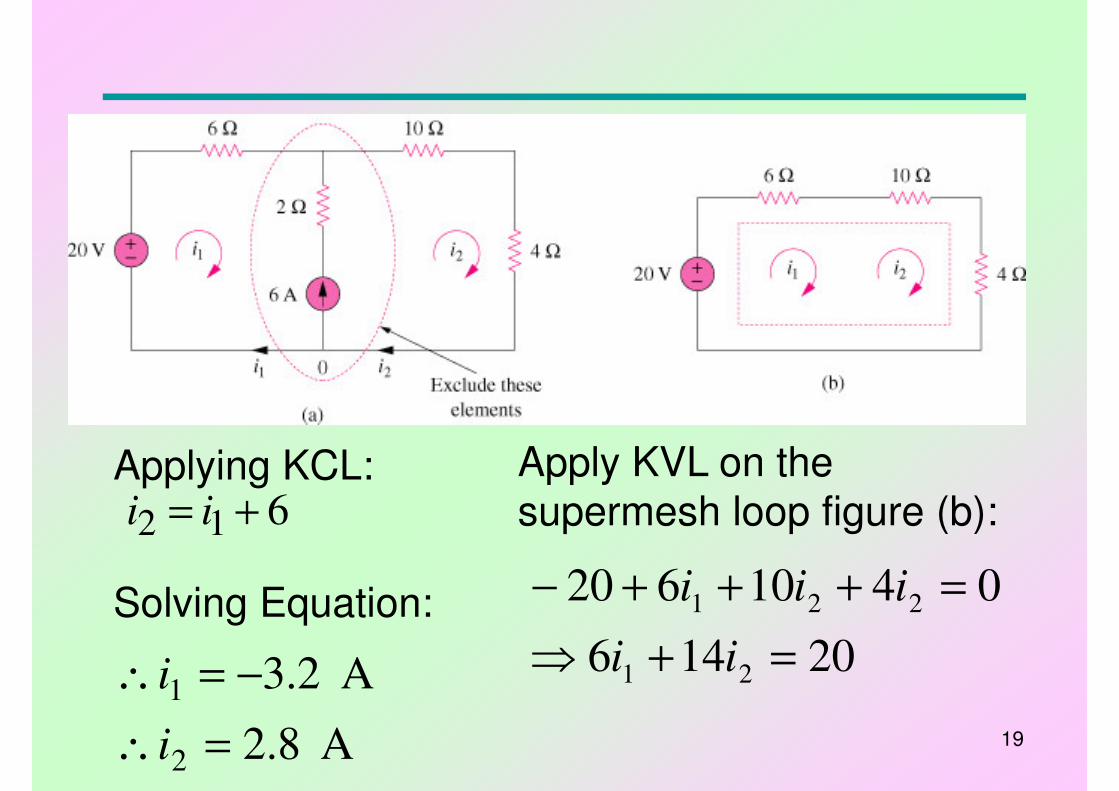
Apply KVL on the supermesh loop figure (b):
20146
0410620
21
221
=+⇒
=+++−
ii
iii
Applying KCL:612 += ii
Solving Equation:
A 8.2
A 2.3
2
1
=∴
−=∴
i
i
20
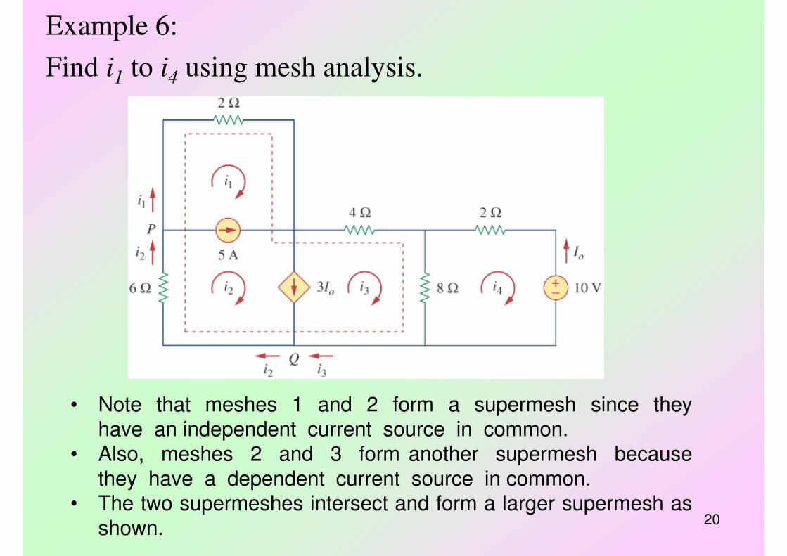
Example 6:
Find i1 to i4 using mesh analysis.
• Note that meshes 1 and 2 form a supermesh since theyhave an independent current source in common.
• Also, meshes 2 and 3 form another supermesh because
they have a dependent current source in common.• The two supermeshes intersect and form a larger supermesh as
shown.
21
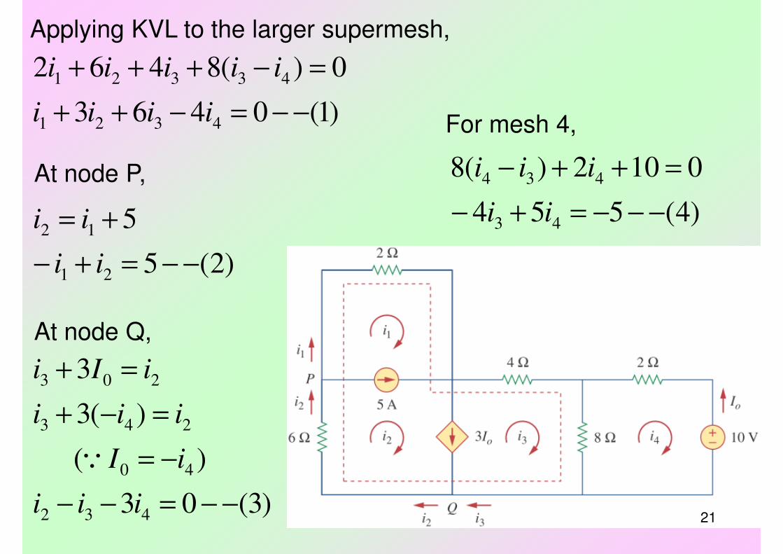
Applying KVL to the larger supermesh,
)1(0463
0)(8462
4321
43321
−−=−++
=−+++
iiii
iiiii
At node P,
)2(5
5
21
12
−−=+−
+=
ii
ii
At node Q,
)3(03
)(
)(3
3
432
40
243
203
−−=−−
−=
=−+
=+
iii
iI
iii
iIi
Q
For mesh 4,
)4(554
0102)(8
43
434
−−−=+−
=++−
ii
iii
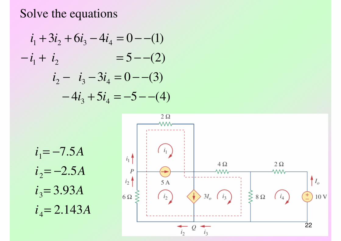
22
)4(554
)3(03
)2(5
)1(0463
43
432
21
4321
−−−=+−
−−=−−
−−=+−
−−=−++
ii
iii
ii
iiii
Solve the equations
Ai
Ai
Ai
Ai
143.2
93.3
5.2
5.7
4
3
2
1
=
=
−=
−=
23
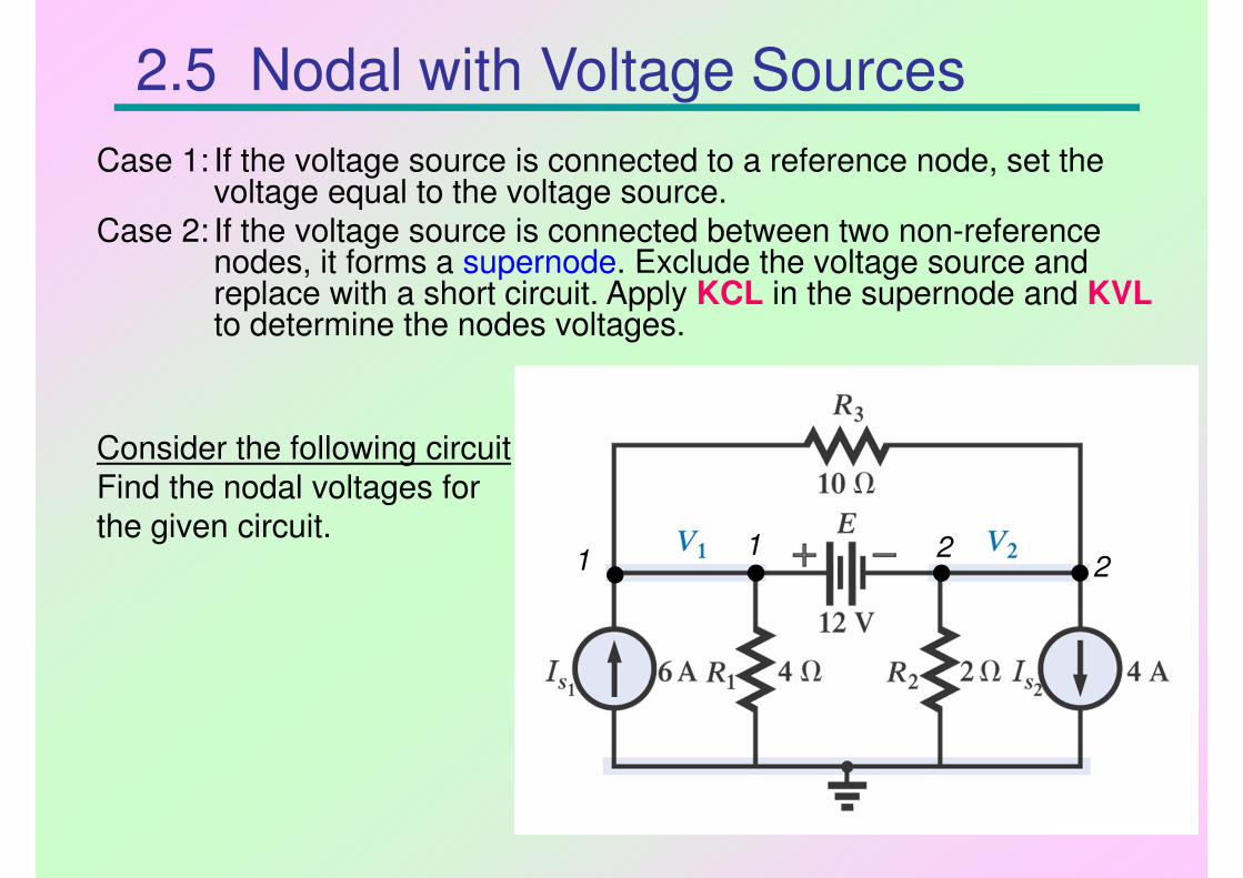
Consider the following circuit
Find the nodal voltages forthe given circuit.
2.5 Nodal with Voltage Sources
Case 1: If the voltage source is connected to a reference node, set the voltage equal to the voltage source.
Case 2: If the voltage source is connected between two non-reference nodes, it forms a supernode. Exclude the voltage source and replace with a short circuit. Apply KCL in the supernode and KVL
to determine the nodes voltages.
1 21 2
24
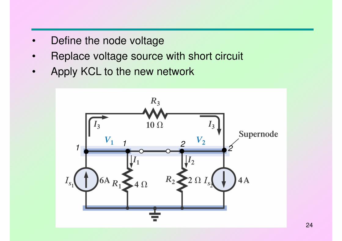
• Define the node voltage
• Replace voltage source with short circuit
• Apply KCL to the new network
1 21 2
25
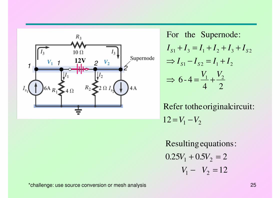
244-6
:SupernodetheFor
21
2121
232131
VV
IIII
IIIIII
SS
SS
+=⇒
+=−⇒
+++=+
2112
:circuit original theRefer to
VV −=
12
250250
:equations Resulting
21
21
=−
=+
V V
V.V.
*challenge: use source conversion or mesh analysis
12V1 2
1 2
26
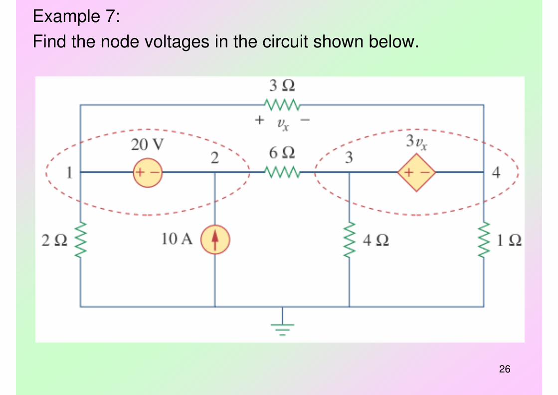
Example 7:
Find the node voltages in the circuit shown below.
27
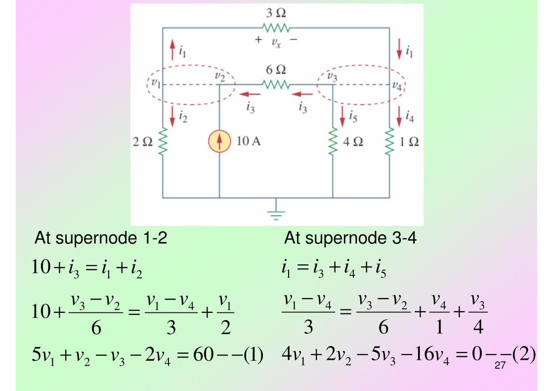
At supernode 1-2
)1(6025
23610
10
4321
14123
213
−−=−−+
+−
=−
+
+=+
vvvv
vvvvv
iii
At supernode 3-4
)2(016524
4163
4321
342341
5431
−−=−−+
++−
=−
++=
vvvv
vvvvvv
iiii
28
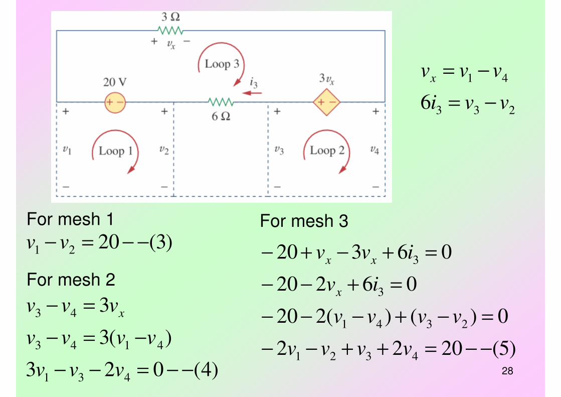
For mesh 1
)3(2021 −−=− vvFor mesh 3
)5(2022
0)()(220
06220
06320
4321
2341
3
3
−−=++−−
=−+−−−
=+−−
=+−+−
vvvv
vvvv
iv
ivv
x
xx
For mesh 2
)4(023
)(3
3
431
4143
43
−−=−−
−=−
=−
vvv
vvvv
vvv x
233
41
6 vvi
vvvx
−=
−=

29
)5( 202 2
)4( 02 3
)3( 20
)2( 016524
)1( 602 5
4321
431
21
4321
4321
−−=++−−
−−=−−
−−=−
−−=−−+
−−=−−+
vvvv
vvv
vv
vvvv
vvvv
Solve the equations
Vv
Vv
Vv
Vv
67.46
33.173
667.6
67.26
4
3
2
1
−=
=
=
=
30
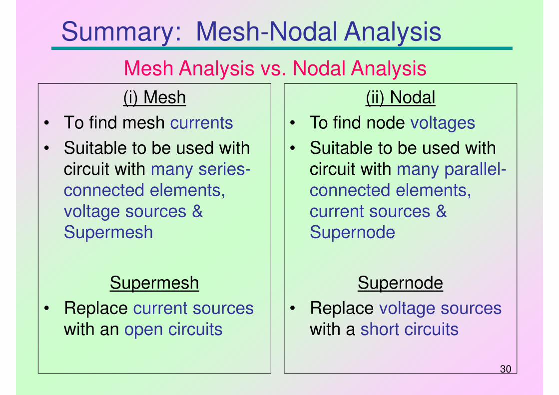
Summary: Mesh-Nodal Analysis
(i) Mesh
• To find mesh currents
• Suitable to be used with
circuit with many series-
connected elements,
voltage sources &
Supermesh
Supermesh
• Replace current sources
with an open circuits
(ii) Nodal
• To find node voltages
• Suitable to be used with
circuit with many parallel-
connected elements,
current sources &
Supernode
Supernode
• Replace voltage sources
with a short circuits
Mesh Analysis vs. Nodal Analysis
31
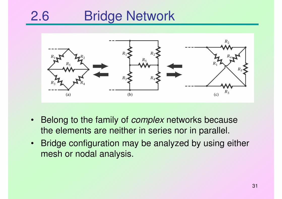
2.6 Bridge Network
• Belong to the family of complex networks because
the elements are neither in series nor in parallel.
• Bridge configuration may be analyzed by using either
mesh or nodal analysis.
32
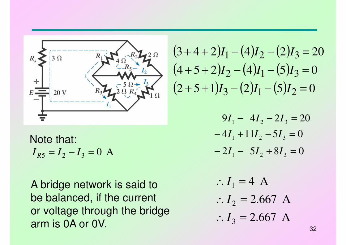
( ) ( ) ( )
( ) ( ) ( )
( ) ( ) ( ) 052152
054254
2024243
213
312
321
=−−++
=−−++
=−−++
III
III
III
0852
05114
20249
321
321
321
=+−−
=−+−
=−−
III
III
III
A 667.2
A 667.2
A 4
3
2
1
=∴
=∴
=∴
I
I
I
Note that:A 0325 =−= III R
A bridge network is said to
be balanced, if the current
or voltage through the bridge
arm is 0A or 0V.