Embed Size (px)
Citation preview
1
Topic # 03Topic # 03
Requirements to Software System: Requirements to Software System: An Overview An Overview
(Ch. 5 and partially Ch. 6)(Ch. 5 and partially Ch. 6)
2
Understanding Requirements: An OverviewUnderstanding Requirements: An Overview
This topic is an overview of Requirements Engineering (RE), and RE is the initial part of huge area in SE – Analysis, Design & Modeling/Prototyping/Simulation.
CS 592 is Requirements Engineering class (with a lot of details on RE including partially UML language) for both undergrad and graduate students is available at the Computer Science curriculum.
RE helps software engineers better UNDERSTAND customer needs, desires, requirements and the problems they are trying to solve.
*) Building an elegant computer solution that ignores the customer’s needs helps no one.
It is very important to understand the customer’s wants and needs before you begin designing or building a computer-based software solution.
The intent of RE is to produce a written formal understanding of the customer’s problem. Several different work products might be used to communicate this understanding, including:
- list of users, - list of functions and features,- use-case scenarios (SwimLane Diagrams, Activity Diagrams, etc.),- Data Flow Diagrams (DFDs),- Data Objects (DOs) diagrams and Class Objects (COs) Diagrams,- Entity-Relationships Diagrams (ERDs),- State Transition Diagrams (STDs),and many other possible analysis models).

3
Requirements Model as a BridgeRequirements Model as a Bridge
system
description
analysis
model
design
model
System Description
(by a customer)
Lists of System Requirements
(that customer still understands)
List of SW System Specifications (diagrams that SW engineers and SW developers understand)
System Development by SW technologists and technicians
4
Requirements Engineering: 6 Majors StepsRequirements Engineering: 6 Majors Steps
The requirements engineering process has 6 distinctive steps: 1) inception (initiation), 2) elicitation (drafting of requirements), 3) elaboration (building an analysis model), 4) negotiation (discussions with a customer), 5) problem specification (written documents/statements/proposed specs), and 6) validation (review) of the proposed specifications (specs).
RE must be adapted to the needs/specifics of a particular project, process, product, or people doing the work.
In some cases RE may be abbreviated (shortened), but it is never abandoned.
5
Step 1: Inception (initiating RE process)Step 1: Inception (initiating RE process)
Inception—ask a set of questions that establish … basic understanding of the problem the people who want a solution the nature of the solution that is desired, and the effectiveness of preliminary communication and collaboration between the customer and
the developer
Main activities on this step (ask millions of good professional questions) :
Identify stakeholders (who are interested in such an application) and their viewpoints
Questions of type A: Focus on customer, stakeholders, overall goals, and benefits of the system Who is behind the request for work? Who will use the solution? What will be the economic benefit of a successful solution? Is there another source for the solution needed?
Questions of type B: Understand the problem and the customer’s perceptions of the solution How would you characterize good output form a successful solution? What problem(s) will this solution address? Can you describe the business environment in which the solution will be used? Will special performance constraints affect the way the solution os approached?
Questions of type C: Focus on communication effectiveness Are you the best person to give “official” answers to these questions? Are my questions relevant to your problem? Am I asking too many questions? Can anyone else provide additional information? Should I be asking you anything else?
6
Step 2: Eliciting (Drafting of) RequirementsStep 2: Eliciting (Drafting of) Requirements
The goal isThe goal is
to identify the problemto identify the problem
propose elements of the solutionpropose elements of the solution
negotiate different approaches, andnegotiate different approaches, and
specify a preliminary set of solution requirementsspecify a preliminary set of solution requirements
Collaborative requirements gathering guidelines
Meetings attended by both developers and customers
Rules for preparation and participation are established
Flexible agenda is used
Facilitator controls the meeting
“Definition mechanism” (e.g. work sheets, stickers, flip sheets, electronic bulletin board) used to determine (estimate) group consensus
7
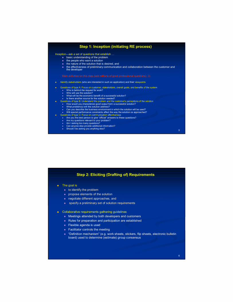
Step 2: Elicitation of Requirements:Step 2: Elicitation of Requirements:An Algorithm (Sequence of Actions) using Activity Diagram in UMLAn Algorithm (Sequence of Actions) using Activity Diagram in UML
Use QFD to
prior it ize
requirem ent s
inform ally
prior it ize
requirem ent s
f orm al pr ior it izat ion?
Create Us e-cases
yes no
El i c it requirem ent s
writ e s cenario
def ine ac tors
complete t em plat e
draw us e-c ase
diagram
Conduc t FAST
m eetings
Mak e list s of
funct ions, c lasses
Make lis ts of
c onst raints , et c.
8
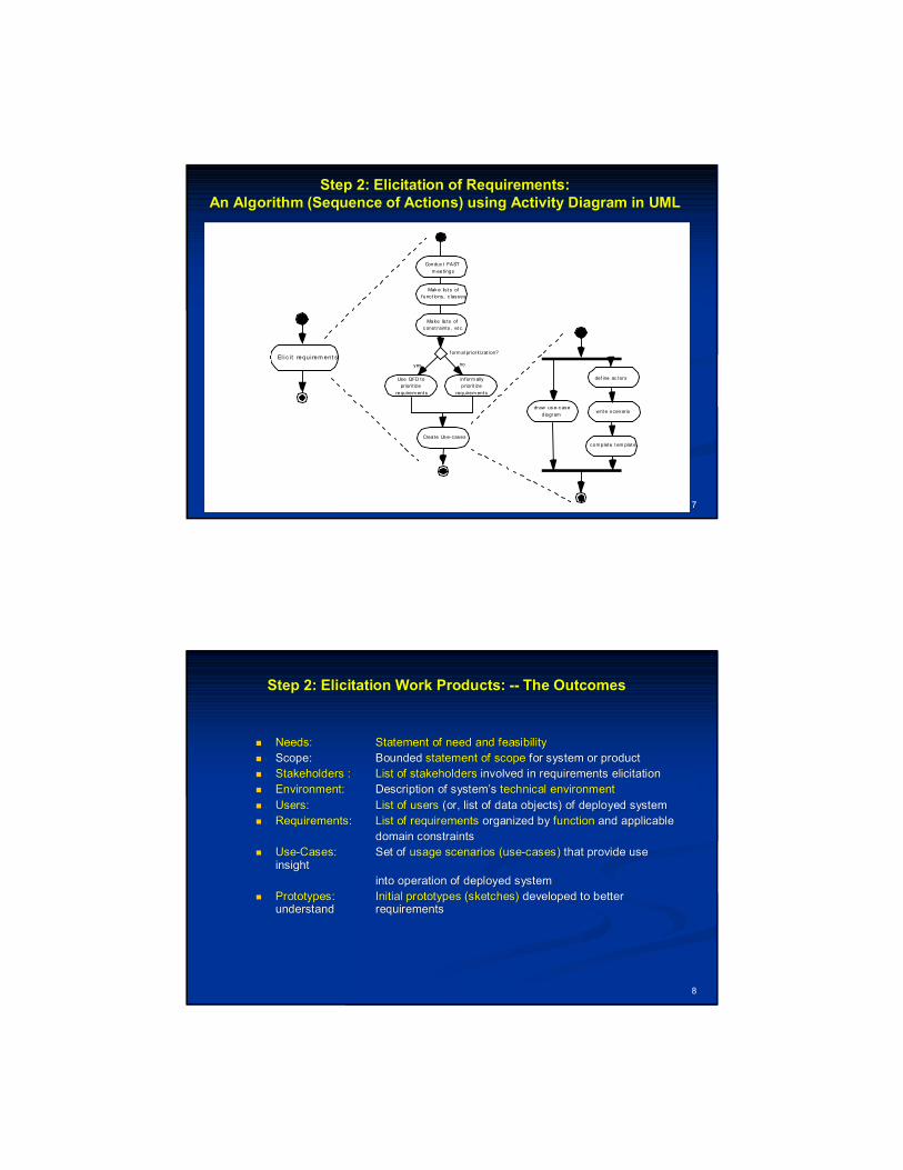
Step 2: Elicitation Work Products: Step 2: Elicitation Work Products: ---- The OutcomesThe Outcomes
Needs: Needs: Statement of need and feasibilityStatement of need and feasibility
Scope: Scope: Bounded Bounded statement of scopestatement of scope for system or productfor system or product
StakeholdersStakeholders : : List of stakeholdersList of stakeholders involved in requirements elicitationinvolved in requirements elicitation
Environment:Environment: Description of system’s Description of system’s technical environmenttechnical environment
Users: Users: List of usersList of users (or, list of data objects) of deployed system(or, list of data objects) of deployed system
Requirements: Requirements: List of requirementsList of requirements organized by organized by functionfunction and applicable and applicable
domain constraintsdomain constraints
UseUse--Cases:Cases: Set of Set of usage scenarios (useusage scenarios (use--cases)cases) that provide use that provide use insight insight
into operation of deployed systeminto operation of deployed system
Prototypes: Prototypes: Initial prototypes (sketches)Initial prototypes (sketches) developed to better developed to better understand understand requirements requirements
9
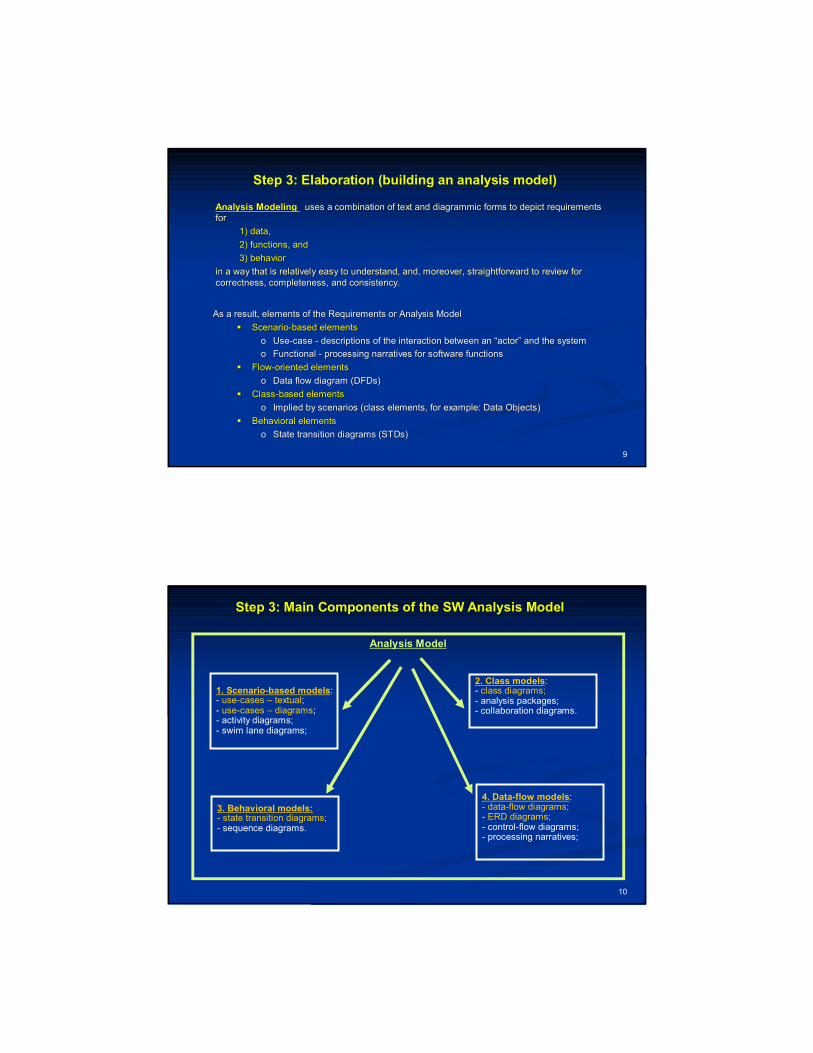
Step 3: Elaboration (building an analysis model)Step 3: Elaboration (building an analysis model)
Analysis ModelingAnalysis Modeling uses a combination of text and uses a combination of text and diagrammicdiagrammic forms to depict requirements forms to depict requirements for for
1) data, 1) data,
2) functions, and 2) functions, and
3) behavior3) behavior
in a way that is relatively easy to understand, and, moreover, sin a way that is relatively easy to understand, and, moreover, straightforward to review for traightforward to review for correctness, completeness, and consistency.correctness, completeness, and consistency.
As a result, elements of the Requirements or Analysis ModelAs a result, elements of the Requirements or Analysis Model
ScenarioScenario--based elementsbased elements
oo UseUse--case case -- descriptions of the interaction between an “actor” and the systdescriptions of the interaction between an “actor” and the systemem
oo Functional Functional -- processing narratives for software functionsprocessing narratives for software functions
FlowFlow--oriented elementsoriented elements
oo Data flow diagram (Data flow diagram (DFDsDFDs))
ClassClass--based elementsbased elements
oo Implied by scenarios (class elements, for example: Data Objects)Implied by scenarios (class elements, for example: Data Objects)
Behavioral elementsBehavioral elements
oo State transition diagrams (STDs)State transition diagrams (STDs)
10
Step 3: Main Components of the SW Analysis ModelStep 3: Main Components of the SW Analysis Model
1. Scenario-based models:- use-cases – textual;- use-cases – diagrams;- activity diagrams;- swim lane diagrams;
Analysis Model
2. Class models:- class diagrams;- analysis packages;- collaboration diagrams.
3. Behavioral models:- state transition diagrams;- sequence diagrams.
4. Data-flow models:- data-flow diagrams;- ERD diagrams;- control-flow diagrams;- processing narratives;
11
Step 4: Negotiation with the CustomerStep 4: Negotiation with the Customer(inform about your current understanding of a problem and (inform about your current understanding of a problem and
ask additional questions if needed)ask additional questions if needed)
Intent is to develop a project plan that meets stakeholder needsIntent is to develop a project plan that meets stakeholder needs and realand real--world world constraints (time, budget, people) placed on the software teamconstraints (time, budget, people) placed on the software team
Negotiation activitiesNegotiation activities Identification of system key stakeholdersIdentification of system key stakeholders Determination of stakeholders’ “win conditions”Determination of stakeholders’ “win conditions” Negotiate to reconcile stakeholders’ win conditions into “winNegotiate to reconcile stakeholders’ win conditions into “win--win” result for all win” result for all
stakeholders (including developers)stakeholders (including developers)
Goal is to produce a winGoal is to produce a win--win result before proceeding to subsequent win result before proceeding to subsequent software engineering activitiessoftware engineering activities
12
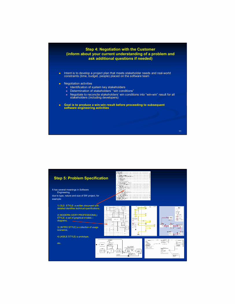
Step 5: Problem SpecificationStep 5: Problem Specification
It has several meanings in Software Engineering
due to type, nature and size of SW project, for
example:
1) OLD STYLE: a written document with detailed identifies technical specifications,
2) MODERN (VERY PROFESSIONAL) STYLE: a set of graphical models –diagrams,
3) (INTRO STYLE) a collection of usage scenarios,
4) (AGILE STYLE) a prototype,
etc.
13
Step 6: Validating Requirements (1/2)Step 6: Validating Requirements (1/2)
SE must be sure that engineered (designed and developed requiremSE must be sure that engineered (designed and developed requirements) provide QUALITY ents) provide QUALITY –– i.e. i.e. they provide clear, precise and concise information/data for thethey provide clear, precise and concise information/data for the Software Development team, Software Development team, including the following:including the following:
GOAL.GOAL. Is each requirement consistent with the overall objective for tIs each requirement consistent with the overall objective for the system/product?he system/product?
LEVEL OF DETAILS.LEVEL OF DETAILS. Have all requirements been specified at the proper level of absHave all requirements been specified at the proper level of abstraction? traction? That is, do some requirements provide a level of technical detaiThat is, do some requirements provide a level of technical detail that is inappropriate at this l that is inappropriate at this stage?stage?
COVERAGE OF ESSENTIAL FEATURES.COVERAGE OF ESSENTIAL FEATURES. Is the requirement really necessary or does it Is the requirement really necessary or does it represent an addrepresent an add--on feature that may not be essential to the objective of the syson feature that may not be essential to the objective of the system?tem?
CLARITY OF REQ.CLARITY OF REQ. Is each requirement bounded and unambiguous?Is each requirement bounded and unambiguous?
SOURCES FOR EACH REQ.SOURCES FOR EACH REQ. Does each requirement have attribution? That is, is a source Does each requirement have attribution? That is, is a source (generally, a specific individual) noted for each requirement? (generally, a specific individual) noted for each requirement?
POTENTIAL CONFLICTS.POTENTIAL CONFLICTS. Do any requirements conflict with other requirements?Do any requirements conflict with other requirements?
14
Step 6: Validating Requirements (2/2)Step 6: Validating Requirements (2/2)
ACHIEVABLE REQ.ACHIEVABLE REQ. Is each requirement achievable in the technical environment thaIs each requirement achievable in the technical environment that will house t will house the system or product?the system or product?
TESTABLE REQ.TESTABLE REQ. Is each requirement testable, once implemented?Is each requirement testable, once implemented?
CORRECTNESS OF REQ.CORRECTNESS OF REQ. Does the requirements model properly reflect the information, fDoes the requirements model properly reflect the information, function unction and behavior of the system to be built.and behavior of the system to be built.
PARTITIONING OF REQ.PARTITIONING OF REQ. Has the requirements model been “partitioned” in a way that expHas the requirements model been “partitioned” in a way that exposes oses progressively more detailed information about the system.progressively more detailed information about the system.
SIMPLICITY OF REQSIMPLICITY OF REQ. Have requirements patterns been used to simplify the requireme. Have requirements patterns been used to simplify the requirements model. nts model. Have all patterns been properly validated? Are all patterns consHave all patterns been properly validated? Are all patterns consistent with customer requirements?istent with customer requirements?
15
Topic # 03Topic # 03
Requirements to Software System: Requirements to Software System: Requirements ModelingRequirements Modeling
(Ch. 5 and partially Ch. 6)(Ch. 5 and partially Ch. 6)
16
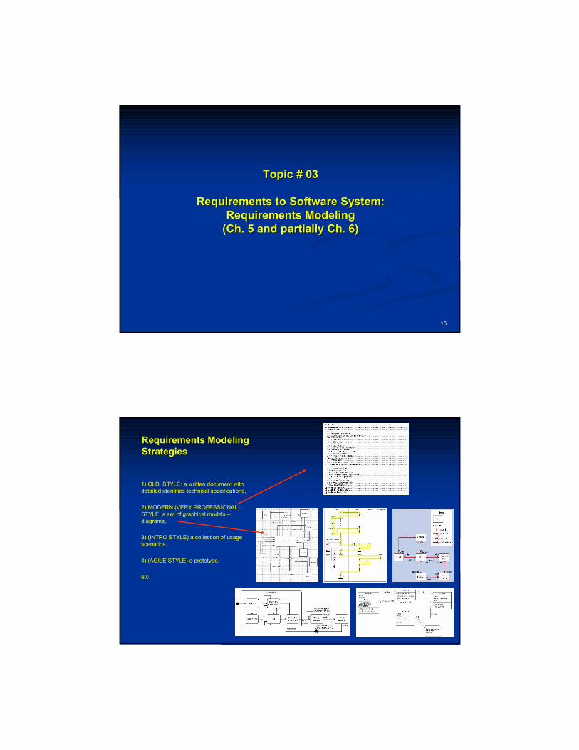
Requirements Modeling Requirements Modeling StrategiesStrategies
1) OLD STYLE: a written document with detailed identifies technical specifications,
2) MODERN (VERY PROFESSIONAL) STYLE: a set of graphical models –diagrams,
3) (INTRO STYLE) a collection of usage scenarios,
4) (AGILE STYLE) a prototype,
etc.
17
Data ObjectsData Objects
18
What is a Data Object? Data Object DiagramsWhat is a Data Object? Data Object Diagrams
ObjectObject -- something that is described by a set something that is described by a set of of attributesattributes(data items) and that will be(data items) and that will be manipulated within the manipulated within the software (system)software (system)
each each instanceinstance of an object (e.g., a book) of an object (e.g., a book)
can be identified uniquely (e.g., ISBN #) can be identified uniquely (e.g., ISBN #)
each plays a necessary role in the systemeach plays a necessary role in the system
i.e., i.e., the system could not function without the system could not function without access to instancesaccess to instances of the objectof the object
each is each is described by attributesdescribed by attributes that are that are themselves data itemsthemselves data items
Data Object Name: Student
Data Object Attributes:firsrt_namelast_nameyear_of_admissionmajorcourses_takencredits_obtainedhome_addressphone_numberemail addressetc.

19
Typical Data ObjectsTypical Data Objects
external entitiesexternal entities (printer, user, sensor)(printer, user, sensor)
thingsthings (e.g, reports, displays, signals) (e.g, reports, displays, signals)
occurrences or eventsoccurrences or events (e.g., interrupt, alarm)(e.g., interrupt, alarm)
rolesroles (e.g., manager, engineer, salesperson)(e.g., manager, engineer, salesperson)
organizational unitsorganizational units (e.g., division, team)(e.g., division, team)
placesplaces (e.g., manufacturing floor) (e.g., manufacturing floor)
data structuresdata structures (e.g., employee record, file, etc.)(e.g., employee record, file, etc.)
20
Class ObjectsClass Objects
21
Class Diagrams
Class DiagramsClass Diagrams are actively used on Classare actively used on Class--based Modelingbased Modeling
Represents:Represents: 1) 1) objects objects system manipulatessystem manipulates
2) 2) operations operations applied to objects, and applied to objects, and
3) 3) collaborations collaborations occurring between classesoccurring between classes
Elements of Elements of class modelclass model include: include:
1) 1) data objectsdata objects
2) 2) attributesattributes
3) 3) operationsoperations
4) 4) collaboration diagramscollaboration diagrams, etc., etc.
Examine the problem statement and try to find nouns that fit the following categories and produce or consume information (i.e. grammatical parse)
External entities (systems, devices, people)
Things (e.g. reports, displays, letters, signals)
Events occurring during system operation
Roles (e.g. manager, engineer, salesperson)
Organizational units (e.g. division, group, team)
Places
Structures (e.g. sensors, vehicles, computers)
22
FRON data Objects TO Class ObjectsFRON data Objects TO Class Objects
What are 4 main What are 4 main
concepts of classconcepts of class--oriented or objectoriented or object--oriented oriented approach?approach?
Abs…Abs…
Enc….Enc….
EnhEnh....
PolPol……

23
ClassClass--Based Modeling: Based Modeling: Data Objects with Attributes and Functions/Methods/OperationsData Objects with Attributes and Functions/Methods/Operations
A data objectA data object contains a set of attributes that act as an aspect, quality, chcontains a set of attributes that act as an aspect, quality, characteristic, or aracteristic, or descriptor of the objectdescriptor of the object
Class Object Name: Student
Class Object Attributes:firsrt_namelast_nameyear_of_admissionmajorcourses_takencredits_obtainedhome_addressphone_numberemail addressetc.
Class Object Functions/Methods:register for a coursepay for a courseget individual course scheduleetc.
24
Class Diagram -- Student Class (1/2):Example of a Conceptual Sketch
Source: http://www.agilemodeling.com/artifacts/classDiagram.htm
25
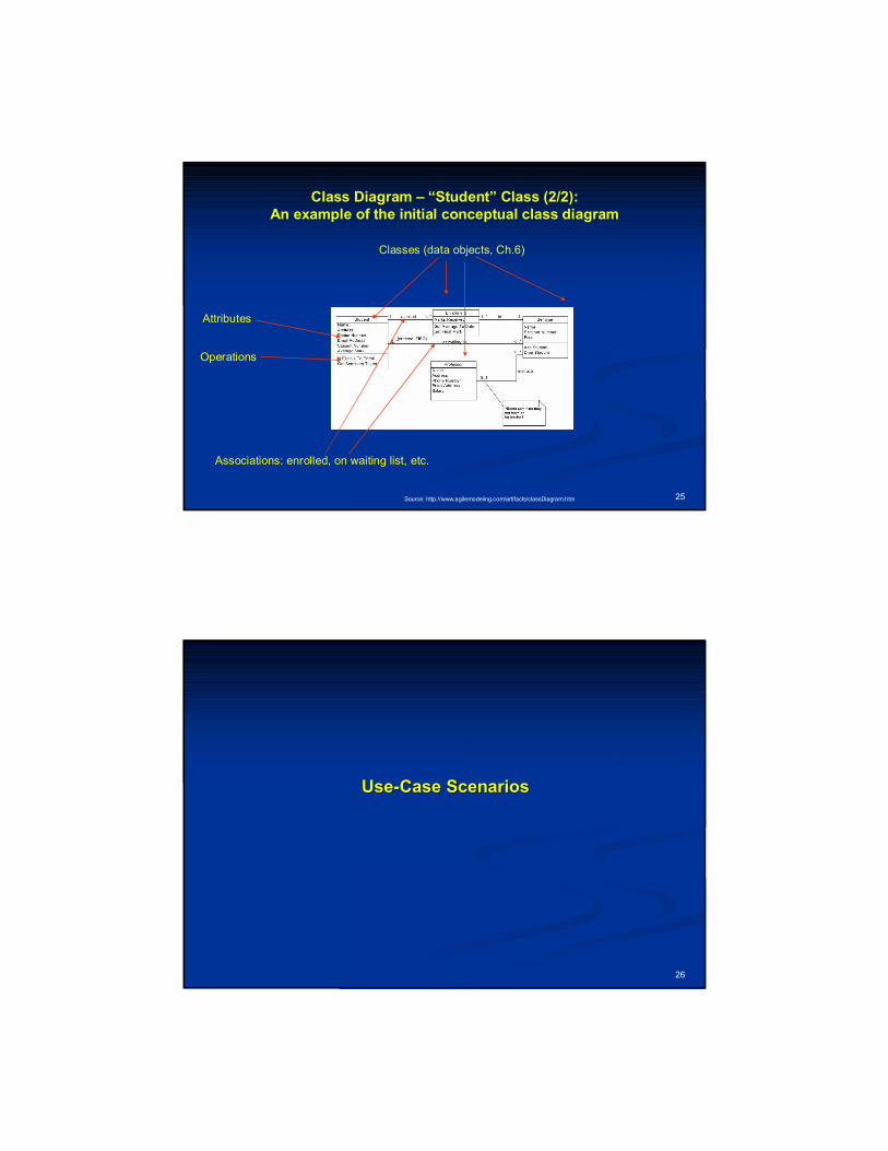
Class Diagram – “Student” Class (2/2):An example of the initial conceptual class diagram
Source: http://www.agilemodeling.com/artifacts/classDiagram.htm
Classes (data objects, Ch.6)
Associations: enrolled, on waiting list, etc.
Attributes
Operations
26
UseUse--Case ScenariosCase Scenarios
27
UseUse--Cases and UseCases and Use--Case ScenariosCase Scenarios
USE CASE is a collection of user scenariosUSE CASE is a collection of user scenarios that describe the thread of usage of a system that describe the thread of usage of a system –– how different users use an old software system or how they willhow different users use an old software system or how they will would like to use a new would like to use a new one.one.
Each Each SINGLE USECASE SCENARIO SINGLE USECASE SCENARIO is described from the pointis described from the point--ofof--view of an “actor”view of an “actor”——a a person or device that interacts with the software in some wayperson or device that interacts with the software in some way
Each Each SINGLE scenarioSINGLE scenario answers the following questions:answers the following questions: Who is the primary actor (user), the secondary actor (s)?Who is the primary actor (user), the secondary actor (s)?
What are the actor’s goals?What are the actor’s goals?
What preconditions should exist before the story begins?What preconditions should exist before the story begins?
What main tasks or functions are performed by the actor?What main tasks or functions are performed by the actor?
What extensions might be considered as the story is described?What extensions might be considered as the story is described?
What variations in the actor’s interaction are possible?What variations in the actor’s interaction are possible?
What system information will the actor acquire, produce, or chanWhat system information will the actor acquire, produce, or change?ge?
Will the actor have to inform the system about changes in the exWill the actor have to inform the system about changes in the external environment?ternal environment?
What information does the actor desire from the system?What information does the actor desire from the system?
Does the actor wish to be informed about unexpected changes?Does the actor wish to be informed about unexpected changes?
28
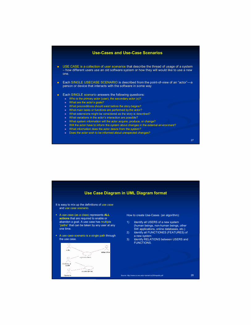
Use Case Diagram in UML Diagram formatUse Case Diagram in UML Diagram format
Source: http://www.cs.wvu.edu/~tanner/cs230/repslds.pdf
It is easy to mix up the definitions of use caseand use case scenario.
A use case (as a class) represents ALL actions that are required to enable or abandon a goal. A use case has multiple “paths” that can be taken by any user at any one time.
A use case scenario is a single path through the use case.
How to create Use-Cases (an algorithm):
1) Identify all USERS of a new system (human beings, non-human beings, other SW applications, online databases, etc.)
2) Identify all FUNCTIONES (FEATURES) of a new system
3) Identify RELATIONS between USERS and FUNCTIONS.
29
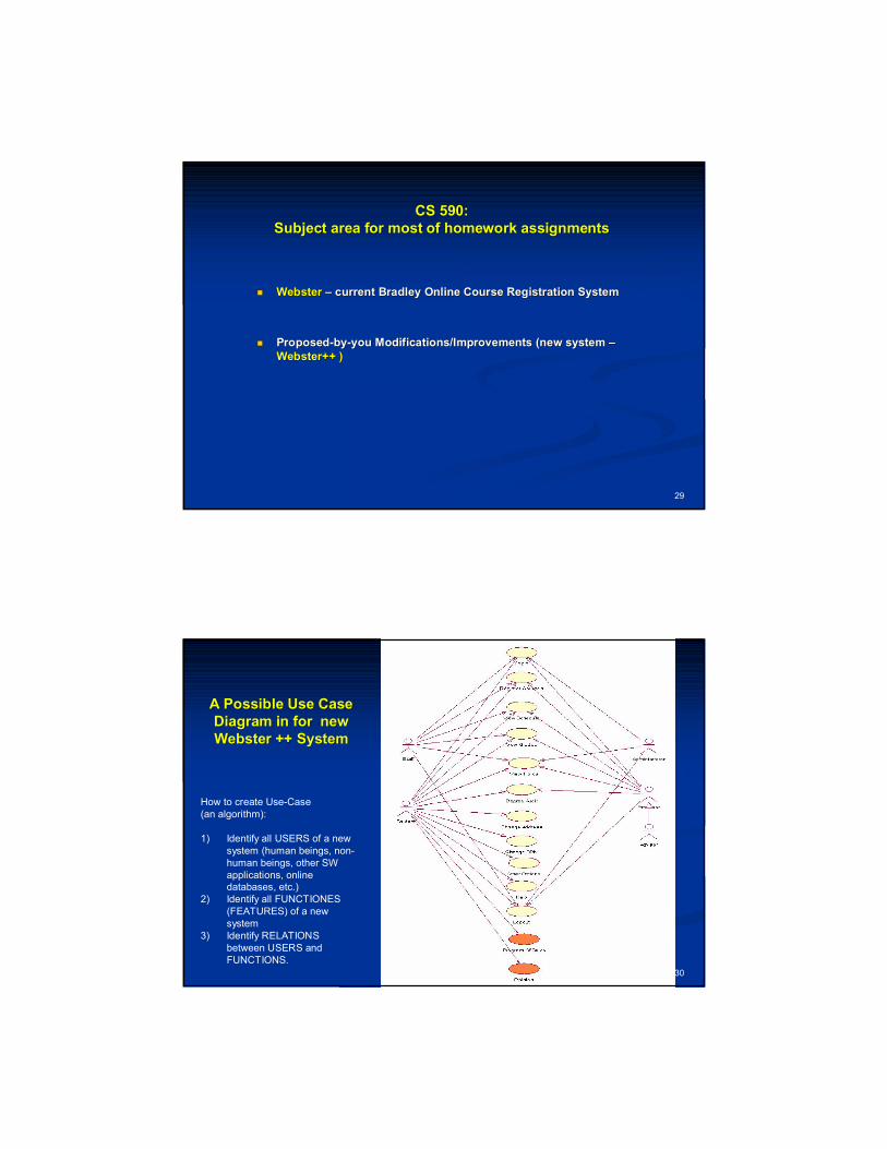
CS 590: CS 590: Subject area for most of homework assignmentsSubject area for most of homework assignments
WebsterWebster –– current Bradley Online Course Registration Systemcurrent Bradley Online Course Registration System
ProposedProposed--byby--you Modifications/Improvements (new system you Modifications/Improvements (new system ––Webster++ )Webster++ )
30
A Possible Use Case A Possible Use Case Diagram in for new Diagram in for new Webster ++ SystemWebster ++ System
How to create Use-Case(an algorithm):
1) Identify all USERS of a new system (human beings, non-human beings, other SW applications, online databases, etc.)
2) Identify all FUNCTIONES (FEATURES) of a new system
3) Identify RELATIONS between USERS and FUNCTIONS.
31
Activity DiagramActivity Diagram
32
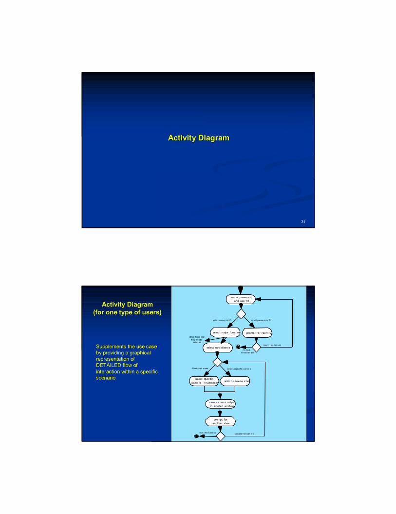
Activity DiagramActivity Diagram(for one type of users)(for one type of users)
ent er password
and user ID
selec t major funct ion
valid passwor ds/ ID
prompt for reent ry
invalid passwor ds/ ID
input t r ies rem ain
no inputt r ies r em ain
select surveillance
ot her f unct ions
m ay also be select ed
t hum bnail views select a specif ic camer a
selec t camera icon
prompt for
anot her view
select specif ic
camera - thumbnails
exit t his f unct ionsee anot her cam er a
view camera output
in labelled window
Supplements the use case by providing a graphical representation of DETAILED flow of interaction within a specific scenario

33
Topic # 03Topic # 03“Requirements to Software System: An overview”“Requirements to Software System: An overview”
Homework AssignmentHomework Assignment
34
SwimLaneSwimLane DiagramsDiagrams
35
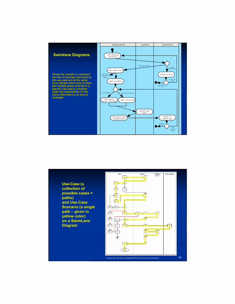
Swimlane DiagramsSwimlane Diagrams
Allows the modeler to represent Allows the modeler to represent the flow of activities described by the flow of activities described by the usethe use--case and at the same case and at the same time indicate which actor (if there time indicate which actor (if there are multiple actors involved in a are multiple actors involved in a specific usespecific use--case) or analysis case) or analysis class has responsibility for the class has responsibility for the action described by an activity action described by an activity rectanglerectangle
enter password
and user ID
select m ajor f unct ion
valid p asswo r d s/ ID
prom pt for reent ry
in validp asswo r d s/ ID
in p u t t r ies
r em ain
n o in p u t
t r ies r em ain
selec t surveillance
o t h er f u n ct io n s m ay also b e
select ed
t h u m b n ail views select a sp ecif ic cam er a
selec t cam era ic on
generate v ideo
output
selec t specif ic
cam era - thum bnails
exit t h isf u n ct io n
see
an o t h ercam er a
h o m e o w n e r c a m e ra i n t e rf a c e
prom pt for
another v iewview cam era output
in labelled window
36
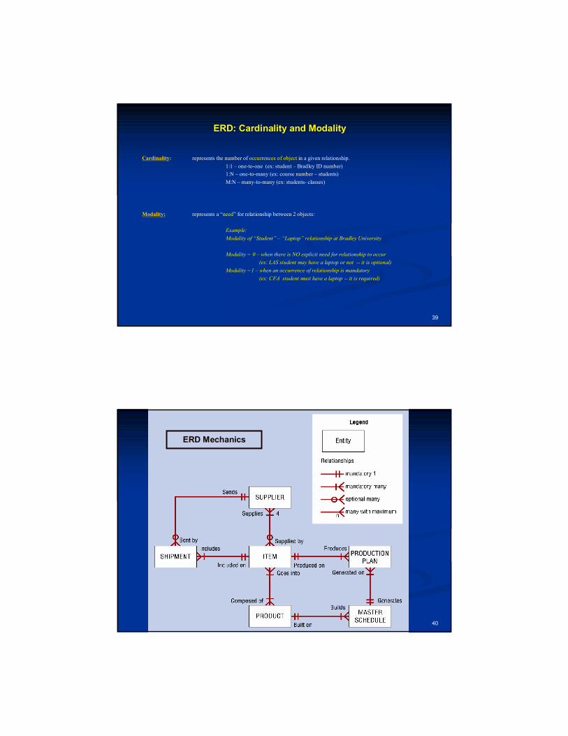
UseUse--Case (a Case (a collection of collection of possible cases = possible cases = paths) paths) and Useand Use--Case Case Scenario (a single Scenario (a single path path –– given in given in yellow color)yellow color)on a on a SwimLaneSwimLaneDiagramDiagram
Source: http://tynerblain.com/blog/2007/04/10/what-are-use-case-scenarios/

37
Modeling of Relationship Between Data Objects Modeling of Relationship Between Data Objects ––ERD (EntityERD (Entity--Relationship Diagrams)Relationship Diagrams)
38
What is a Relationship?What is a Relationship?
Relationship Relationship -- indicates “connectedness”; a "fact" that must be indicates “connectedness”; a "fact" that must be "remembered“ by the system and cannot or is not "remembered“ by the system and cannot or is not computed or derived mechanicallycomputed or derived mechanically
1) several instances of a relationship can exist1) several instances of a relationship can exist2) objects can be related in many different ways2) objects can be related in many different ways
39
ERD: Cardinality and ModalityERD: Cardinality and Modality
Cardinality: represents the number of occurrences of object in a given relationship.
1:1 – one-to-one (ex: student – Bradley ID number)
1:N – one-to-many (ex: course number – students)
M:N – many-to-many (ex: students- classes)
Modality: represents a “need” for relationship between 2 objects:
Example:
Modality of “Student” – “Laptop” relationship at Bradley University
Modality = 0 – when there is NO explicit need for relationship to occur
(ex: LAS student may have a laptop or not -- it is optional)
Modality =1 – when an occurrence of relationship is mandatory
(ex: CFA student must have a laptop -- it is required)
40
ERD Mechanics
41
Topic # 03Topic # 03
Requirements to Software System: Requirements to Software System: Additional InformationAdditional Information
42
UseUse--Case and UseCase and Use--Case Scenario Case Scenario in UML’s Swimlane format in UML’s Swimlane format –– Ch. 6, p. 163 (1/2)Ch. 6, p. 163 (1/2)
It is easy to mix up the definitions of use case and use case scenario.
A use case (as a class) represents ALL actions that are required to enable or abandon a goal. A use case has multiple “paths” that can be taken by any user at any one time.
A use case scenario is a single path through the use case.
Source: http://tynerblain.com/blog/2007/04/10/what-are-use-case-scenarios/


![Software Requirements - The Process Groupprocessgroup.com/software-requirements-v10-full.pdf · What is a Software Requirement? ... [Based on K. Wiegers Software Requirements]](https://img.pdfslide.us/doc/110x75/5b7ba4ad7f8b9ab87f8e69be/software-requirements-the-process-what-is-a-software-requirement-based.jpg)