Embed Size (px)
Citation preview

TOP Server V5 to MicroLogix 1400
Using DNP3 Ethernet Driver

Page 2 of 36
Table of Contents
INTRODUCTION 3
CONFIGURING THE MICROLOGIX 1400 AS A DNP3 SLAVE 4
CONFIGURING TOP SERVER AS A DNP3 MASTER 9
TESTING DEVICE CONNECTION WITH OPC QUICK CLIENT 20
DNP3 CLASS POLLING CONFIGURATION - CONTROLLER 22
DNP3 CLASS POLLING CONFIGURATION – TOP SERVER 24
DNP3 TIME SYNC AND UNSOLICITED MESSAGING - CONTROLLER 27

Page 3 of 36
Introduction
This document is meant as a quick-start reference for getting TOP Server V5 connected to your
AB MicroLogix 1400 Series B controller using DNP3 Ethernet. It is not meant to replace vendor
documentation and guides for configuring DNP3 capabilities in an AB MicroLogix 1400 controller.
Page 4 of 36
Configuring the MicroLogix 1400 as a DNP3 Slave
1. Create a new MicroLogix 1400 Series B project using RSLogix 500/Micro version 8.30 or higher.
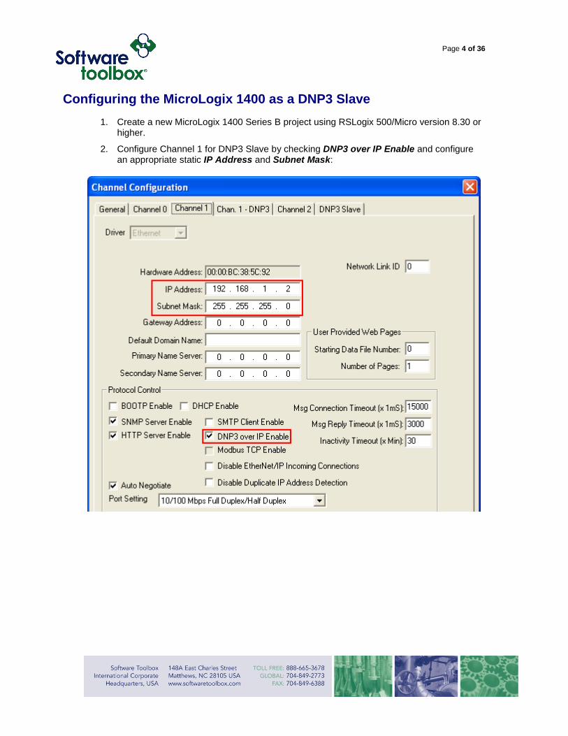
2. Configure Channel 1 for DNP3 Slave by checking DNP3 over IP Enable and configure an appropriate static IP Address and Subnet Mask:

Page 5 of 36
3. Click on the Chan. 1 - DNP3 tab. Enter 10 for Diagnostic File Number and leave the other fields at their default values for now:

Page 6 of 36
4. The Diagnostic File is used to store and display Channel Status diagnostic information specific to DNP3 over Ethernet:

Page 7 of 36
5. Click on the DNP3 Slave tab:

Page 8 of 36
6. Enter 3 for Binary Input DNP3 Object Data File Number:
7. At this point we have mapped bits B3/0-B3/15 as16 Binary Inputs (Index 0-15). DNP Binary Inputs are assigned to Group Number 1. They can be read from TOP Server in “packed format” using Variation 1 or “with flags” using Variation 2.
8. Click Apply to save the channel configuration and download the file to a MicroLogix 1400 (using Ethernet or the channel 2 serial port). Be sure to apply the channel configuration at the end of the download.
9. Switch the MicroLogix to Remote Run mode.

Page 9 of 36
Configuring TOP Server as a DNP3 Master
1. Next, if you haven’t already, download and install the TOP Server DNP3 Ethernet OPC server.
2. After the installation is complete, run TOP Server.
3. Click on Click to add a channel, enter Ethernet for the Channel name and click Next:

Page 10 of 36
4. Select DNP Master Ethernet for the Device driver, check Enable diagnostics and click
Next:
5. Select the appropriate Network Adapter and click Next:

Page 11 of 36
6. Leave Write Optimizations at default values and click Next:
7. Leave Virtual Network as None and click Next:

Page 12 of 36
8. Configure the Destination IP address to match the MicroLogix 1400 IP address and click Next:
9. Leave Channel Timing settings at default and click Next:
Page 13 of 36
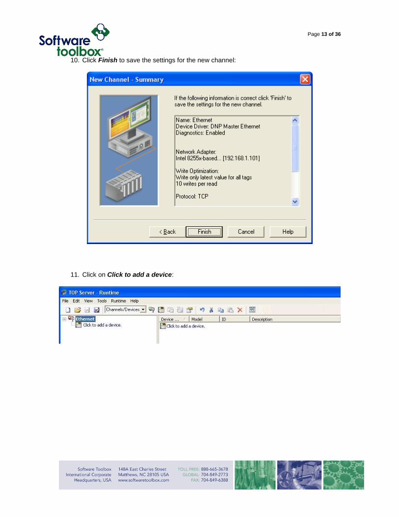
10. Click Finish to save the settings for the new channel:
11. Click on Click to add a device:

Page 14 of 36
12. Enter MicroLogix 1400 for Device Name and click Next:
13. Enter 0 for Master Address and 1 for Slave Address and click Next:

Page 15 of 36
14. Leave Time Sync Style as LAN and click Next:
15. In the Event Class Polling settings, disable the polling for now by setting the Event Class
X Poll Intervals to zero and click Next:

Page 16 of 36
16. In the Integrity Polling settings, disable the polling for now by setting the Integrity Poll Interval to zero, uncheck the check boxes and click Next:
17. Leave Unsolicited Mode Class X as Automatic and click Next:

Page 17 of 36
18. Leave Enable Event Buffer unchecked and click Next:
19. Leave Operate Mode as Direct Operate, make sure both check boxes are checked and
click Next:

Page 18 of 36
20. Click Finish to save the settings for the new device:
21. Next click Click to add a static tag:

Page 19 of 36
22. Enter B3/0 for the Name and 1.1.0.Explicit (Group 0.Variation 1.Index 0) for the Address. Verify Boolean for the Data type, Read Only for the Client access, and leave Scan Rate at 100 milliseconds. Click Apply and then OK:
23. Your TOP Server is now configured with a single DNP3 tag:

Page 20 of 36
Testing Device Connection with OPC Quick Client
1. Click Tools and select OPC Quick Client:
2. Click on Ethernet.MicroLogix 1400 and, if your Ethernet connection is correct, the status of Quality for this tag should be Good, indicating that the value of tag B3/0 has been read out of the MicroLogix 1400:
3. Because we gave the tag address an Explicit sub-type, TOP Server is reading this specific binary input once a second. We can see the read command initiated by TOP Server and the response from the MicroLogix in the following Wireshark Ethernet packet captures:

Page 21 of 36
4. Note that there is no timestamp returned in this read response, so the OPC Quick Client timestamp is the computer time when the last data value change was received.
5. By design, DNP3 is an event driven protocol, so there is no need for TOP Server to constantly read a value in order to determine whether it changed or not. Now, we will go back and configure the MicroLogix to generate an event (with timestamp) every time bit B3/0 gets toggled, and configure TOP Server to poll for events instead of constantly reading individual values.

Page 22 of 36
DNP3 Class Polling Configuration - Controller
1. Go offline with the MicroLogix 1400 and in the DNP3 Slave channel configuration tab, create a Binary Input Class file by entering in the next available data table file number, 11, clicking Yes to Size (in # of elements) 1, and clicking OK to apply the channel configuration:
2. Word B11:0 now defines the Class (1, 2 or 3) for Binary Inputs 0-15. We will assign these Binary Inputs to Class 1 by setting the value of B11:0 to 1:

Page 23 of 36
3. Now all we have to do is download the updated file to the MicroLogix. Whenever bit B3/0 toggles, an event will automatically be generated.
4. Now if you go online with the MicroLogix and monitor the Channel 1 – Ext tab under Channel Status while toggling bit B3/0 on and off, you should see the Number of events to be reported incrementing:

Page 24 of 36
DNP3 Class Polling Configuration – TOP Server
1. Next we need to modify the TOP Server driver so that it polls for Class 1 events, instead of constantly reading B3/0.
2. Close OPC Quick Client if you haven’t already, then on TOP Server, double click on tag B3/0 and change the Address from 1.1.0.Explicit to 1.1.0.Value and click OK:

Page 25 of 36
3. Click on MicroLogix 1400 to bring up the Device Properties and then click on the Class Polling tab. Enter 5 for the Event Class 1 Poll Interval and 3600 for the Integrity Poll Interval, check Restart and Slave Online, and then click OK:
4. Now TOP Server will transmit a Class 0 (Integrity) Poll every hour, to which the MicroLogix will respond with the current (static) value of every configured DNP point (currently Binary Inputs 0-15), and every 5 seconds TOP Server will poll for any Class 1 events that have been logged by the MicroLogix.
5. This time open up OPC Quick Client by clicking on the QC icon:

Page 26 of 36
6. Click on Ethernet.MicroLogix 1400 and, if your Ethernet connection is correct, the status of Quality tag B3/0 should be Good, indicating that the value of this tag has been read out of the MicroLogix 1400:
7. The Class 1 poll that TOP Server is sending is requesting Variation 2, which is the event data with an absolute timestamp. Notice that TOP Server assumes that the RTU timestamp is set to UTC, but if it’s not, there will be a time offset in the timestamp based on the PC’s time zone setting.
8. Now if you go back to being online with the MicroLogix and monitor the Channel 1 – Ext tab under Channel Status, you should see the Number of events to be reported at zero, because the MicroLogix already transmitted the logged events in response to TOP Server’s Class 1 poll.
9. Currently the MicroLogix timestamp is based on its own RTC, because we left its time sync configuration at default, which is none.
Page 27 of 36
DNP3 Time Sync and Unsolicited Messaging - Controller
1. Now we will go back and set the MicroLogix to sync up with the Master after a power cycle and every hour thereafter.
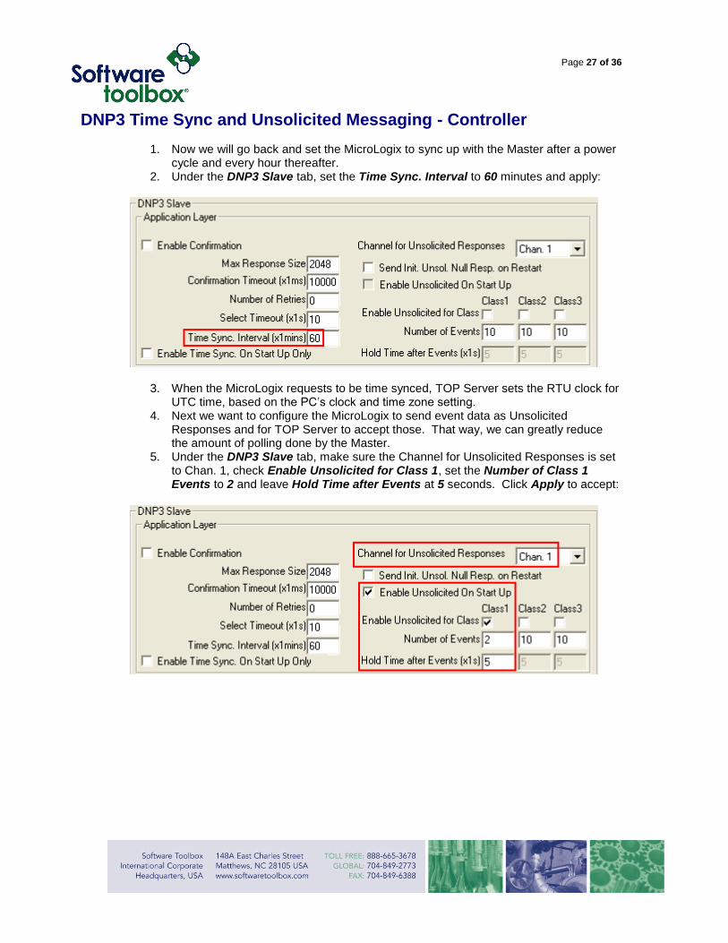
2. Under the DNP3 Slave tab, set the Time Sync. Interval to 60 minutes and apply:
3. When the MicroLogix requests to be time synced, TOP Server sets the RTU clock for UTC time, based on the PC’s clock and time zone setting.
4. Next we want to configure the MicroLogix to send event data as Unsolicited Responses and for TOP Server to accept those. That way, we can greatly reduce the amount of polling done by the Master.
5. Under the DNP3 Slave tab, make sure the Channel for Unsolicited Responses is set to Chan. 1, check Enable Unsolicited for Class 1, set the Number of Class 1 Events to 2 and leave Hold Time after Events at 5 seconds. Click Apply to accept:

Page 28 of 36
6. Close OPC Quick Client if you haven’t already. In TOP Server, double click on MicroLogix 1400 and under the Unsolicited tab, change Unsolicited Class 1 Mode to Enable and click Apply to accept:

Page 29 of 36
7. Next, under the Class Polling tab, set the Event Class 1 Poll Interval to 0. This will stop TOP Server from polling except for an Integrity Poll every hour (based on the current settings). Click OK:
8. Open up OPC Quick Client again by clicking on the QC icon:

Page 30 of 36
9. Click on Ethernet.MicroLogix 1400 and, if your Ethernet connection is correct, the status of Quality for tag B3/0 should be Good. Notice that after toggling bit B3/0 in the MicroLogix 1400, that the time stamp now shows local time because the RTC in the controller was synchronized to UTC time by the DNP3 Master, but displayed in local time based on the TOP Server setting :
10. Next, go online with the MicroLogix and display both Channel 1 – Ext Channel Status and the B3 Data File. Toggle bit B3:0/0 once and you should see Number of events to be reported increment to 1 and then go back to zero after five seconds. You should also see Trans Unsolicited Res FC Counter increment by 1, as well as Received Confirm FC Counter:

Page 31 of 36
11. If you toggle B3/0 twice in less than five seconds, you should see that the Unsolicited Response was sent immediately based on the Channel Status counters. This behavior is due to the Unsolicited Response configuration in the MicroLogix. Rather than trigger an Unsolicited Response after every event, the MicroLogix will wait until either two events have been generated, or five seconds since the first event was generated, whichever comes first:
12. Next let’s look at the effect of the online/offline flag for Binary Input 0. By default, BI0 is offline when the MicroLogix is in Program mode and online when the MicroLogix is in Run mode.
13. Switch the MicroLogix to Remote Program mode. Now when you toggle B3/0, the tag’s Quality will indicate Bad:
14. Return the MicroLogix to Remote Run mode, toggle B3/0 and note that the Quality returns to Good.

Page 32 of 36
15. If you want to have control over the online/offline flag while the controller is in Run mode, you may create a Binary Input Online/Offline file in the MicroLogix. Go offline with the MicroLogix and enter in 12 for the Binary Input Flag/OL config file on the DNP3 Slave Channel Configuration tab. Click Apply and then Yes to Size (in # of elements) 1:
16. Now download this program to the MicroLogix and go to Run mode. Notice that in OPC Quick Client, the Quality is still Bad for B3/0. This is because bits B12/0-15 now indicate whether Binary Inputs B3/0-15 are online (=1) or offline (=0). Set bit B12/0 to 1, toggle bit B3/0 to initiate an Unsolicited Response and now the Quality should change to Good. The Quality will still indicate Bad if an Unsolicited Response is generated while the controller is in Program mode.
17. Next we will create mappings for Analog Inputs and configure them to generate Unsolicited Responses as well. There are three DNP3 Analog Input types supported by the MicroLogix: Integer (16-bit), Long or DINT (32-bit) and Float or REAL (32-bit).

Page 33 of 36
10. After going offline with the MicroLogix, enter in the numbers listed below on the DNP3 Slave Channel Configuration tab. Click Apply and then Yes to Size (in # of elements) 1 for all files:
11. Go ahead and download the updated file to the MicroLogix, switch the MicroLogix to Run and go online.
12. We have now configured three DNP3 Analog Inputs that we can read in OPC Quick Client after we create the tags in TOP Server. First close OPC Quick Client. Analog Inputs are Group 30 objects. We are going to read N7 using Variation 4 (16-bit without flags), L9 using Variation 3 (32-bit without flags) and F8 using Variation 5 (short floating point with flags). These Variations are the default Variations returned by the MicroLogix when an Integrity (Class 0) poll is received. The index numbering starts in the 16-bit “Short” integer file, then continues in the 32-bit “Long” integer file and then concludes in the 32-bit “Float” file. Create the three additional tags as shown below in TOP Server:

Page 34 of 36
13. Restart OPC Quick Client and notice that while the Quality for L9 and N7 is Good, it is still Bad for F8. This is because F8 Variation includes Flags, and we haven’t set its Online bit yet:
14. The Flag bits for Analog Inputs are contained in the Class Config Files. Therefore, we will set the Class of each of the Analog Inputs to 2 (by setting bit 1 in each of their Class Config words) and set the Online bit on (by setting bit 8 in the same word).
15. In order to set up Unsolicited Response capability for the Analog Inputs, we need to enable Class 2 Unsolicited Responses in the MicroLogix and then make the corresponding changes in TOP Server. While Online with the MicroLogix, go to the Channel Configuration DNP3 Slave tab, check Enable Unsolicited for Class 2 and set the Number of Events to 2. Click OK and Apply.

Page 35 of 36
16. Close OPC Quick Client if you haven’t already. In TOP Server, double-click on MicroLogix 1400 and under the Unsolicited tab, change Unsolicited Class 2 Mode to Enable and click OK to accept:
17. Next, double click on each of the Analog tags and change their Address from *.Explicit to *.Value and click OK:
18. Open OPC Quick Client and verify that Quality is Good on all of the tags:

Page 36 of 36
19. Change each analog input in the MicroLogix data table and verify that the new Value is displayed and the Update Count increments:
20. Notice that currently any change to these analog inputs will generate an event. It is more typical to apply a “deadband” around the analog input values within which an event won’t be generated. We previously created the Deadband Config Files for these analog inputs, however we left them at their default values of 0. While online with the MicroLogix, apply more useful deadbands: 10 in N16:0 for N7, 0.1 in F18:0 for F8 and 100000 in L17:0 for L9. Verify for yourself that adding or subtracting a value less than or equal to the deadband will not trigger an event, but a value greater than the deadband does trigger an event and an Unsolicited Response with the new Value.