Embed Size (px)
Citation preview
Page 1 of 12
Subject to change:-
Last Change:-
Issue:- C/Note:- Date:- By:- Auth.:- 1 19/11/03
PAC
CUSTOMER
SPECIFICATION
33//44 iinncchh BBSSPP WWaatteerr VVaallvveess
For liquid and gas mediums
Contents
- Scope
- Compliance & Reference standards
- Functional Requirements
- Technical Specification
- Environmental Specification
- Physical Dimensions
Page 2 of 12
Subject to change:-
Last Change:-
Issue:- C/Note:- Date:- By:- Auth.:- 1 19/11/03
PAC
CUSTOMER
SPECIFICATION
Scope
This specification outlines guaranteed features and performance of the valve. Due to ongoing improvements,
the manufacturer reserves the right to alter the specifications without prior notification.
Compliance to Standards:
SAA MP52 Spec 6.30
IEC 730-2-1 & IEC 730-2-8
AS4020
BS6920.1 & BS6290.2
AS C3169
AS1722
AS3169
ASTM B 117
UL94
IEC 695-2-1
Functional Requirements:
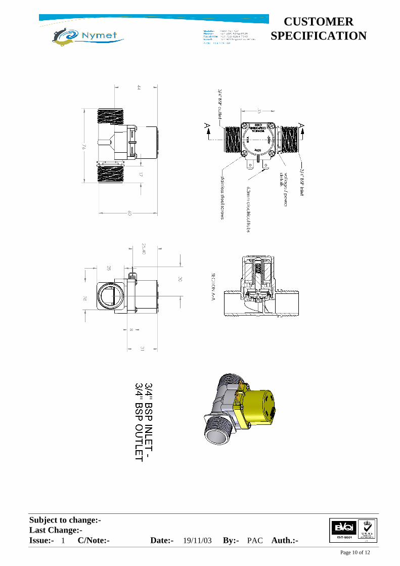
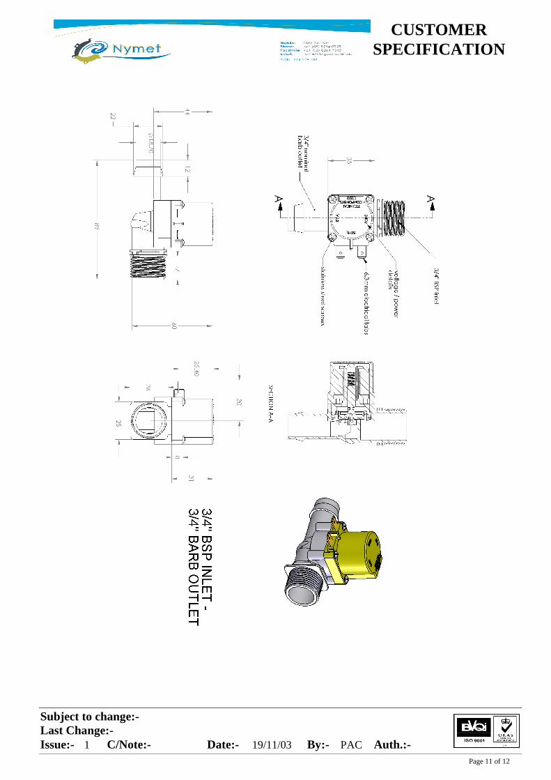
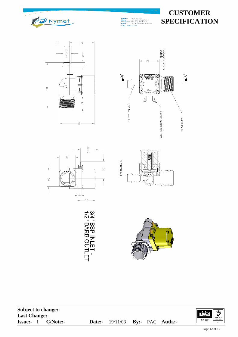
Standard piping configurations are made to the inlet of the valve by connecting via the ¾” BSP
male thread connection. The outlet of the valve is available in various configurations. These being
either 3/4" BSP male thread, 10.5mm barb, 1/2" barb or 3/4" barb. The barb outlets are intended to
be connected with a flexible hose. This product has been designed to meet all requirements
enabling it to be connected to a mains water supply provided it meets the Hydraulic Performance
Criteria stated in this specification.
For best performance especially at low pressures, the valve should be mounted in a horizontal
position with the solenoid standing in an upright position.
Standard electrical connections are made via the two 6.3mm tabs protruding from the valve. It is
advisable to ensure that the electrical receptacles connecting the tabs are insulated.
Page 3 of 12
Subject to change:-
Last Change:-
Issue:- C/Note:- Date:- By:- Auth.:- 1 19/11/03
PAC
CUSTOMER
SPECIFICATION
Technical Specifications
Unless otherwise specified, the following specifications refer to an ambient temperature 25 ± 5 ˚ C.
Ambient Conditions
The valve will operate correctly within the following temperature conditions;
- Ambient temperature: 2˚ C to 60˚ C
- Relative humidity : 0% to 100%
- Temperature of water: 2˚ C to 80˚ C
Inlet and Outlet Configurations
Inlet
¾” BSP thread Male (AS1722)
Outlet
3/4" BSP thread male, 10.5mm barb, 1/2" barb, 3/4" barb
Markings
The following are clearly visible
- The manufacturers name
- Model type number
- Nominal voltage, frequency, and power rating
- Date Code
- Direction of flow arrow
Materials
Page 4 of 12
Subject to change:-
Last Change:-
Issue:- C/Note:- Date:- By:- Auth.:- 1 19/11/03
PAC
CUSTOMER
SPECIFICATION
Body Nylon 66 30% Glass filled
Upper housing Nylon 66 30% Glass filled
Diaphragm Natural Nitrile elastomers
Plunger : Steel Magnetic Stainless Steel grade specially developed for water valves
Tip Natural Nitrile elastomers
Spring Stainless Steel 302
Bracket Zinc plated Mild steel
Screws Stainless steel 304
Filter Stainless steel 304- 40 mesh x 34 gauge
Regulator washer Nitrile
(Optional)
Cup Natural Nylon 66
Solenoid Encapsulant Nylon 66 30% glass filled
Terminals 6.3mm Quick connect type to AS3169, - tin plated brass
Coil Former Nylon 66 25% glass filled
Copper magnet Solderable Polyester enamel. Temp index of enamel >155˚C
Wire
Resistance to bursting pressure
Page 5 of 12
Subject to change:-
Last Change:-
Issue:- C/Note:- Date:- By:- Auth.:- 1 19/11/03
PAC
CUSTOMER
SPECIFICATION
Minimum static bursting pressure > 6.5 Mpa (65 bar), reached through a gradual pressure increase spread
over 20 seconds starting from atmospheric pressure.
Resistance to external pressure peaks (water hammer peaks)
The valve will withstand 100 cycles of 5.0 Mpa transient peaks (peak width of 200ms)
Resistance to pulling out
The coil on the appliance valve does not move or pull out from its original position when subjected to a
gradually applied force which is parallel to the plunger housing spindle of no less than 50N (5.1 Kg).
Strength of coupling thread
With a minimum of 5 full threads engaged, the inlet and outlet coupling threads do not strip or break
when subjected to a tightening torque of 30Nm.
Potable water contact
All non-metallic materials in contact with water have potable water certification to AS4020, and/or
BS6920 parts 1&2, and/or current approvals with FDA & WRC.
All metallic materials in contact with water, comply with AS4020, or contain not more than 4.5% lead
(0.1% lead for solders) and 0.05% cadmium.
Corrosion resistance of stainless steels
The stainless steels pass the salt spray fog test according to ASTM B 117 salt spray fog test. Stay time
100 hours. After having been dried in ambient temperatures, there are no rust spots present. A small
yellow discolouration is acceptable.
Solenoid resistance to fire
Solenoid coil former and encapsulant are rated to UL94 – V0 and/or Glow wire-
IEC 695-2-1, 960˚ C
Resistance to arc tracking / earth leakage
Solenoid assemblies are flash tested to 3.3 – 3.5kV ac, 50 Hz between earthed parts and live parts of
opposite polarity.
Operating pressure range
Page 6 of 12
Subject to change:-
Last Change:-
Issue:- C/Note:- Date:- By:- Auth.:- 1 19/11/03
PAC
CUSTOMER
SPECIFICATION
The valve operates correctly between 20Kpa and 1250kPa (0.2 – 12.5 bar), at the inlet of the valve.
Opening pressure drop
The valve is designed to comply with IEC730-2-8 clause 18.101.3
Operating Pressure Rise (Water Hammer Peak)
Static Pressure ranges = 20 kPa to 1250kPa (0.7 bar – 12.5 bar)
Supply pipe velocity range =1.2 m/s to 6.5 m/s
Immediately after closure, the pressure peak is not to exceed 115% of the initial static pressure condition.
Opening Response Time
Flow established within 0.5 sec of power application
Closing Response Time
Within 0.5 sec after power is removed
Leaking under pressure
Max seepage admitted in the whole of the pressure range is 10ml/12 Hours
Dynamic Life
10 valves are sequentially cycled. One valve on for 3 seconds all valves off for 3 seconds, next valve on
for 3 seconds and so on.
1(one) cycle is complete after all 10 valves have been opened and closed.
The valves survive 25,000 cycles at a water temperature of 80˚ C and a static pressure of 1500 kPa (15
bar)
Static Life
As per Australian standard SAA MP52 Specification No. 030, clause 6.30.7, which is:
Plastic bodied valves shall be capable of withstanding a hydrostatic test pressure of 3.0 +0.5 Mpa for 60
+5 mins at the manufactures stated maximum operating temperature without leakage.
Abnormal pressure conditions
Page 7 of 12
Subject to change:-
Last Change:-
Issue:- C/Note:- Date:- By:- Auth.:- 1 19/11/03
PAC
CUSTOMER
SPECIFICATION
In certain installations there is the possibility of trapped excess pressure in the line between the valve inlet
and supply inlet. This condition may arise when other valves or taps shut off and cause transient high
pressure peaks through out the plumbing system.
The valve will open in the following adverse condition:
Rated voltage - 10%
Coil temperature = 25 ± 5˚ C prior to power on
Trapped pressure released = up to 2000kPa (20 bar)
Electrical
Voltage Voltage Frequency Power Holding Inrush Ambient Water Duty Cycle
Tolerance Hz Consumption Current Current Temp Temp min on /
% VA mA mA ˚C ˚C min off
240Vac +10 / -10 50 8 33 42 60 60 continuous
30 80 continuous 60 80 continuous
Voltage Voltage Frequency Power Holding Inrush Ambient Water Duty Cycle
Tolerance Hz Consumption Current Current Temp Temp min on /
% VA mA mA ˚C ˚C min off
120Vac +10 / -10 60 8 66 142 60 60 continuous
30 80 continuous
60 80 continuous
Voltage Voltage Frequency Power Holding Inrush Ambient Water Duty Cycle
Tolerance Hz Consumption Current Current Temp Temp min on /
% VA mA mA ˚C ˚C min off
24Vac +10 / -10 50 8 260 320 60 60 continuous
30 80 continuous
60 80 continuous
Voltage Voltage Frequency Power Holding Inrush Ambient Water Duty Cycle
Tolerance Hz Consumption Current Current Temp Temp min on /
% VA mA mA ˚C ˚C min off
12Vdc +10 / -10 - 8 600 600 60 60 continuous
30 80 continuous
60 80 continuous
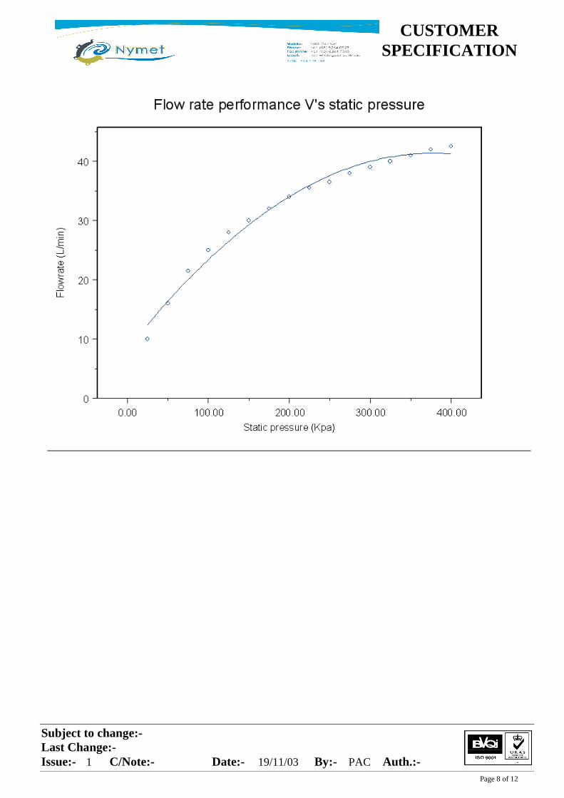
Page 8 of 12
Subject to change:-
Last Change:-
Issue:- C/Note:- Date:- By:- Auth.:- 1 19/11/03
PAC
CUSTOMER
SPECIFICATION
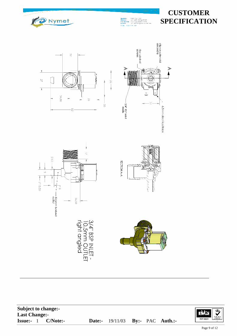
Page 9 of 12
Subject to change:-
Last Change:-
Issue:- C/Note:- Date:- By:- Auth.:- 1 19/11/03
PAC
CUSTOMER
SPECIFICATION
Page 10 of 12
Subject to change:-
Last Change:-
Issue:- C/Note:- Date:- By:- Auth.:- 1 19/11/03
PAC
CUSTOMER
SPECIFICATION
Page 11 of 12
Subject to change:-
Last Change:-
Issue:- C/Note:- Date:- By:- Auth.:- 1 19/11/03
PAC
CUSTOMER
SPECIFICATION
Page 12 of 12
Subject to change:-
Last Change:-
Issue:- C/Note:- Date:- By:- Auth.:- 1 19/11/03
PAC
CUSTOMER
SPECIFICATION


![Technical Reference Guide for Medical & Pharmaceutical ......[0.4–0.7] 0.5 [0.3–0.7] 0.6 [0.5–0.7] Gurley Hill Porosity TAPPI T4601 ISO 5636-53 sec/100 cc 22 [8–36] 20 [8–36]](https://img.pdfslide.us/doc/110x75/60409397e8e102733e79fd82/technical-reference-guide-for-medical-pharmaceutical-04a07-05.jpg)